Embed Size (px)
Citation preview
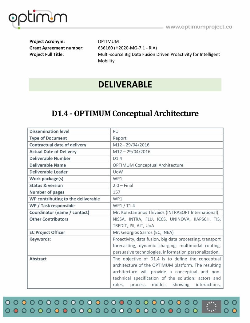
Project Acronym: OPTIMUM
Grant Agreement number: 636160 (H2020-MG-7.1 - RIA)
Project Full Title: Multi-source Big Data Fusion Driven Proactivity for Intelligent
Mobility
DELIVERABLE
D1.4 - OPTIMUM Conceptual Architecture
Dissemination level PU
Type of Document Report
Contractual date of delivery M12 - 29/04/2016
Actual Date of Delivery M12 – 29/04/2016
Deliverable Number D1.4
Deliverable Name OPTIMUM Conceptual Architecture
Deliverable Leader UoW
Work package(s) WP1
Status & version 2.0 – Final
Number of pages 157
WP contributing to the deliverable WP1
WP / Task responsible WP1 / T1.4
Coordinator (name / contact) Mr. Konstantinos Thivaios (INTRASOFT International)
Other Contributors NISSA, INTRA, FLU, ICCS, UNINOVA, KAPSCH, TIS,
TREDIT, JSI, AIT, UoA
EC Project Officer Mr. Georgios Sarros (EC, INEA)
Keywords: Proactivity, data fusion, big data processing, transport
forecasting, dynamic charging, multimodal routing,
persuasive technologies, information personalization.
Abstract The objective of D1.4 is to define the conceptual
architecture of the OPTIMUM platform. The resulting
architecture will provide a conceptual and non-
technical specification of the solution: actors and
roles, process models showing interactions,
Project Title: OPTIMUM
Contract No. 636160 Project Coordinator: INTRASOFT International S.A.
Page 2
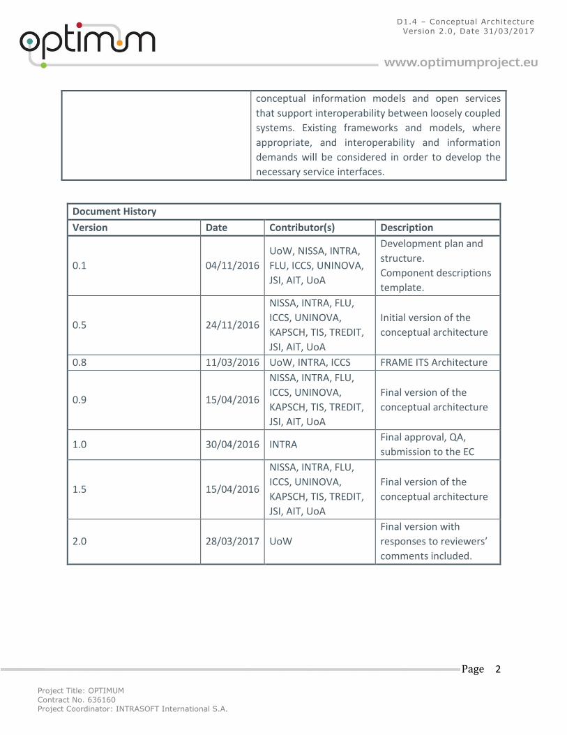
D1.4 – Conceptual Architecture
Version 2.0, Date 31/03/2017
conceptual information models and open services
that support interoperability between loosely coupled
systems. Existing frameworks and models, where
appropriate, and interoperability and information
demands will be considered in order to develop the
necessary service interfaces.
Document History
Version Date Contributor(s) Description
0.1 04/11/2016
UoW, NISSA, INTRA,
FLU, ICCS, UNINOVA,
JSI, AIT, UoA
Development plan and
structure.
Component descriptions
template.
0.5 24/11/2016
NISSA, INTRA, FLU,
ICCS, UNINOVA,
KAPSCH, TIS, TREDIT,
JSI, AIT, UoA
Initial version of the
conceptual architecture
0.8 11/03/2016 UoW, INTRA, ICCS FRAME ITS Architecture
0.9 15/04/2016
NISSA, INTRA, FLU,
ICCS, UNINOVA,
KAPSCH, TIS, TREDIT,
JSI, AIT, UoA
Final version of the
conceptual architecture
1.0 30/04/2016 INTRA Final approval, QA,
submission to the EC
1.5 15/04/2016
NISSA, INTRA, FLU,
ICCS, UNINOVA,
KAPSCH, TIS, TREDIT,
JSI, AIT, UoA
Final version of the
conceptual architecture
2.0 28/03/2017 UoW
Final version with
responses to reviewers’
comments included.
Project Title: OPTIMUM
Contract No. 636160 Project Coordinator: INTRASOFT International S.A.
Page 3
D1.4 – Conceptual Architecture
Version 2.0, Date 31/03/2017
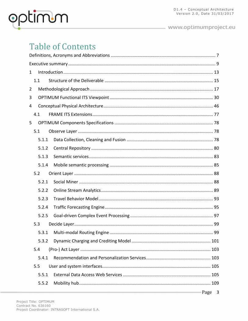
Table of Contents Definitions, Acronyms and Abbreviations ...................................................................................... 7
Executive summary ......................................................................................................................... 9
1 Introduction ........................................................................................................................... 13
1.1 Structure of the Deliverable ......................................................................................... 15
2 Methodological Approach ..................................................................................................... 17
3 OPTIMUM Functional ITS Viewpoint ..................................................................................... 30
4 Conceptual Physical Architecture .......................................................................................... 46
4.1 FRAME ITS Extensions ................................................................................................... 77
5 OPTIMUM Components Specifications ................................................................................. 78
5.1 Observe Layer ............................................................................................................... 78
5.1.1 Data Collection, Cleaning and Fusion ....................................................................... 78
5.1.2 Central Repository .................................................................................................... 80
5.1.3 Semantic services ...................................................................................................... 83
5.1.4 Mobile semantic processing ..................................................................................... 85
5.2 Orient Layer .................................................................................................................. 88
5.2.1 Social Miner .............................................................................................................. 88
5.2.2 Online Stream Analytics ............................................................................................ 89
5.2.3 Travel Behavior Model .............................................................................................. 93
5.2.4 Traffic Forecasting Engine ......................................................................................... 95
5.2.5 Goal-driven Complex Event Processing .................................................................... 97
5.3 Decide Layer .................................................................................................................. 99
5.3.1 Multi-modal Routing Engine ..................................................................................... 99
5.3.2 Dynamic Charging and Crediting Model ................................................................. 101
5.4 (Pro-) Act Layer ........................................................................................................... 103
5.4.1 Recommendation and Personalization Services ..................................................... 103
5.5 User and system interfaces ......................................................................................... 105
5.5.1 External Data Access Web Services ........................................................................ 105
5.5.2 Mobility hub ............................................................................................................ 109
Project Title: OPTIMUM
Contract No. 636160 Project Coordinator: INTRASOFT International S.A.
Page 4
D1.4 – Conceptual Architecture
Version 2.0, Date 31/03/2017
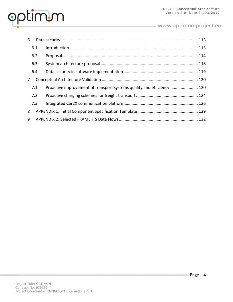
6 Data security ........................................................................................................................ 113
6.1 Introduction ................................................................................................................ 113
6.2 Proposal ...................................................................................................................... 114
6.3 System architecture proposal ..................................................................................... 118
6.4 Data security in software implementation ................................................................. 119
7 Conceptual Architecture Validation .................................................................................... 120
7.1 Proactive improvement of transport systems quality and efficiency ........................ 120
7.2 Proactive charging schemes for freight transport ...................................................... 124
7.3 Integrated Car2X communication platform ................................................................ 126
8 APPENDIX 1: Initial Component Specification Template ..................................................... 129
9 APPENDIX 2: Selected FRAME ITS Data Flows ..................................................................... 132
Project Title: OPTIMUM
Contract No. 636160 Project Coordinator: INTRASOFT International S.A.
Page 5
D1.4 – Conceptual Architecture
Version 2.0, Date 31/03/2017
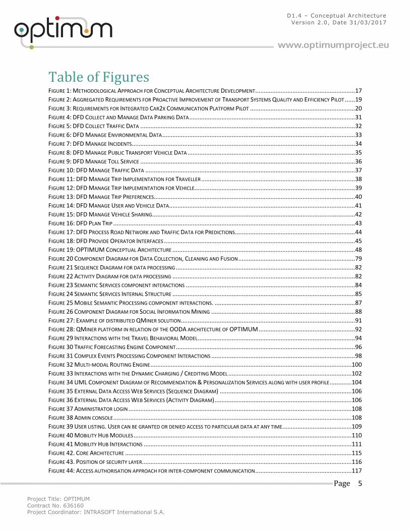
Table of Figures FIGURE 1: METHODOLOGICAL APPROACH FOR CONCEPTUAL ARCHITECTURE DEVELOPMENT ........................................................... 17 FIGURE 2: AGGREGATED REQUIREMENTS FOR PROACTIVE IMPROVEMENT OF TRANSPORT SYSTEMS QUALITY AND EFFICIENCY PILOT ...... 19 FIGURE 3: REQUIREMENTS FOR INTEGRATED CAR2X COMMUNICATION PLATFORM PILOT .............................................................. 20 FIGURE 4: DFD COLLECT AND MANAGE DATA PARKING DATA .................................................................................................. 31 FIGURE 5: DFD COLLECT TRAFFIC DATA ............................................................................................................................... 32 FIGURE 6: DFD MANAGE ENVIRONMENTAL DATA .................................................................................................................. 33 FIGURE 7: DFD MANAGE INCIDENTS .................................................................................................................................... 34 FIGURE 8: DFD MANAGE PUBLIC TRANSPORT VEHICLE DATA ................................................................................................... 35 FIGURE 9: DFD MANAGE TOLL SERVICE ............................................................................................................................... 36 FIGURE 10: DFD MANAGE TRAFFIC DATA ............................................................................................................................ 37 FIGURE 11: DFD MANAGE TRIP IMPLEMENTATION FOR TRAVELLER ........................................................................................... 38 FIGURE 12: DFD MANAGE TRIP IMPLEMENTATION FOR VEHICLE............................................................................................... 39 FIGURE 13: DFD MANAGE TRIP PREFERENCES....................................................................................................................... 40 FIGURE 14: DFD MANAGE USER AND VEHICLE DATA .............................................................................................................. 41 FIGURE 15: DFD MANAGE VEHICLE SHARING ........................................................................................................................ 42 FIGURE 16: DFD PLAN TRIP ............................................................................................................................................... 43 FIGURE 17: DFD PROCESS ROAD NETWORK AND TRAFFIC DATA FOR PREDICTIONS ....................................................................... 44 FIGURE 18: DFD PROVIDE OPERATOR INTERFACES ................................................................................................................. 45 FIGURE 19: OPTIMUM CONCEPTUAL ARCHITECTURE ............................................................................................................ 48 FIGURE 20 COMPONENT DIAGRAM FOR DATA COLLECTION, CLEANING AND FUSION ..................................................................... 79 FIGURE 21 SEQUENCE DIAGRAM FOR DATA PROCESSING .......................................................................................................... 82 FIGURE 22 ACTIVITY DIAGRAM FOR DATA PROCESSING ............................................................................................................ 82 FIGURE 23 SEMANTIC SERVICES COMPONENT INTERACTIONS .................................................................................................... 84 FIGURE 24 SEMANTIC SERVICES INTERNAL STRUCTURE ............................................................................................................ 85 FIGURE 25 MOBILE SEMANTIC PROCESSING COMPONENT INTERACTIONS. ................................................................................... 87 FIGURE 26 COMPONENT DIAGRAM FOR SOCIAL INFORMATION MINING ..................................................................................... 88 FIGURE 27: EXAMPLE OF DISTRIBUTED QMINER SOLUTION ....................................................................................................... 91 FIGURE 28: QMINER PLATFORM IN RELATION OF THE OODA ARCHITECTURE OF OPTIMUM ......................................................... 92 FIGURE 29 INTERACTIONS WITH THE TRAVEL BEHAVIORAL MODEL ............................................................................................. 94 FIGURE 30 TRAFFIC FORECASTING ENGINE COMPONENT .......................................................................................................... 96 FIGURE 31 COMPLEX EVENTS PROCESSING COMPONENT INTERACTIONS ..................................................................................... 98 FIGURE 32 MULTI-MODAL ROUTING ENGINE ....................................................................................................................... 100 FIGURE 33 INTERACTIONS WITH THE DYNAMIC CHARGING / CREDITING MODEL ......................................................................... 102 FIGURE 34 UML COMPONENT DIAGRAM OF RECOMMENDATION & PERSONALIZATION SERVICES ALONG WITH USER PROFILE ............. 104 FIGURE 35 EXTERNAL DATA ACCESS WEB SERVICES (SEQUENCE DIAGRAM) .............................................................................. 106 FIGURE 36 EXTERNAL DATA ACCESS WEB SERVICES (ACTIVITY DIAGRAM) ................................................................................. 106 FIGURE 37 ADMINISTRATOR LOGIN .................................................................................................................................... 108 FIGURE 38 ADMIN CONSOLE ............................................................................................................................................. 108 FIGURE 39 USER LISTING. USER CAN BE GRANTED OR DENIED ACCESS TO PARTICULAR DATA AT ANY TIME ......................................... 109 FIGURE 40 MOBILITY HUB MODULES ................................................................................................................................. 110 FIGURE 41 MOBILITY HUB INTERACTIONS ........................................................................................................................... 111 FIGURE 42. CORE ARCHITECTURE ...................................................................................................................................... 115 FIGURE 43. POSITION OF SECURITY LAYER ............................................................................................................................ 116 FIGURE 44: ACCESS AUTHORISATION APPROACH FOR INTER-COMPONENT COMMUNICATION ......................................................... 117
Project Title: OPTIMUM
Contract No. 636160 Project Coordinator: INTRASOFT International S.A.
Page 6
D1.4 – Conceptual Architecture
Version 2.0, Date 31/03/2017
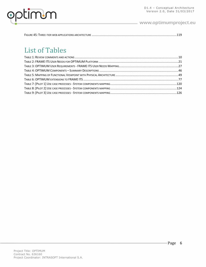
FIGURE 45: THREE-TIER WEB APPLICATIONS ARCHITECTURE .................................................................................................... 119
List of Tables TABLE 1: REVIEW COMMENTS AND ACTIONS .......................................................................................................................... 10 TABLE 2: FRAME ITS USER NEEDS FOR OPTIMUM PLATFORM .............................................................................................. 21 TABLE 3: OPTIMUM USER REQUIREMENTS - FRAME ITS USER NEEDS MAPPING...................................................................... 27 TABLE 4: OPTIMUM COMPONENTS – SUMMARY DESCRIPTIONS ............................................................................................. 46 TABLE 5: MAPPING OF FUNCTIONAL VIEWPOINT WITH PHYSICAL ARCHITECTURE .......................................................................... 49 TABLE 6: OPTIMUM EXTENSIONS TO FRAME ITS ................................................................................................................ 77 TABLE 7: [PILOT 1] USE CASE PROCESSES - SYSTEM COMPONENTS MAPPING .............................................................................. 120 TABLE 8: [PILOT 2] USE CASE PROCESSES - SYSTEM COMPONENTS MAPPING .............................................................................. 124 TABLE 9: [PILOT 3] USE CASE PROCESSES - SYSTEM COMPONENTS MAPPING .............................................................................. 126
Project Title: OPTIMUM
Contract No. 636160 Project Coordinator: INTRASOFT International S.A.
Page 7
D1.4 – Conceptual Architecture
Version 2.0, Date 31/03/2017
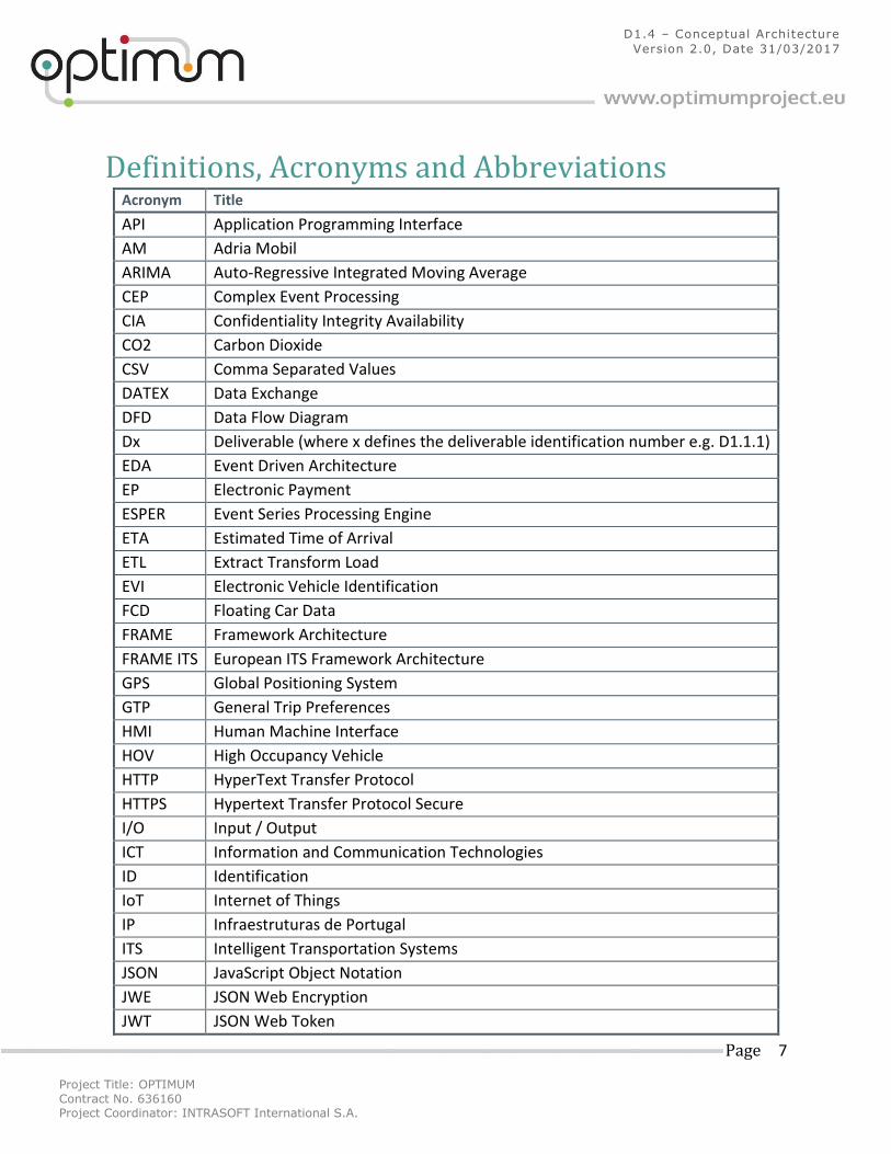
Definitions, Acronyms and Abbreviations Acronym Title
API Application Programming Interface
AM Adria Mobil
ARIMA Auto-Regressive Integrated Moving Average
CEP Complex Event Processing
CIA Confidentiality Integrity Availability
CO2 Carbon Dioxide
CSV Comma Separated Values
DATEX Data Exchange
DFD Data Flow Diagram
Dx Deliverable (where x defines the deliverable identification number e.g. D1.1.1)
EDA Event Driven Architecture
EP Electronic Payment
ESPER Event Series Processing Engine
ETA Estimated Time of Arrival
ETL Extract Transform Load
EVI Electronic Vehicle Identification
FCD Floating Car Data
FRAME Framework Architecture
FRAME ITS European ITS Framework Architecture
GPS Global Positioning System
GTP General Trip Preferences
HMI Human Machine Interface
HOV High Occupancy Vehicle
HTTP HyperText Transfer Protocol
HTTPS Hypertext Transfer Protocol Secure
I/O Input / Output
ICT Information and Communication Technologies
ID Identification
IoT Internet of Things
IP Infraestruturas de Portugal
ITS Intelligent Transportation Systems
JSON JavaScript Object Notation
JWE JSON Web Encryption
JWT JSON Web Token
Project Title: OPTIMUM
Contract No. 636160 Project Coordinator: INTRASOFT International S.A.
Page 8
D1.4 – Conceptual Architecture
Version 2.0, Date 31/03/2017
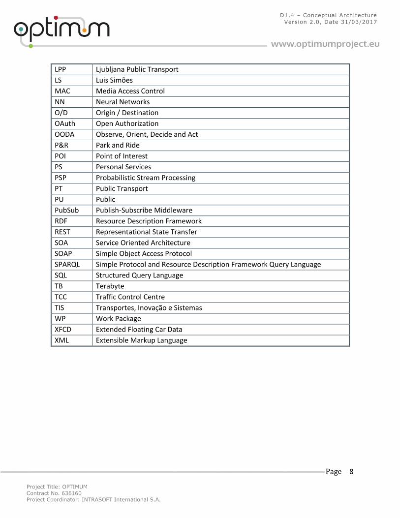
LPP Ljubljana Public Transport
LS Luis Simões
MAC Media Access Control
NN Neural Networks
O/D Origin / Destination
OAuth Open Authorization
OODA Observe, Orient, Decide and Act
P&R Park and Ride
POI Point of Interest
PS Personal Services
PSP Probabilistic Stream Processing
PT Public Transport
PU Public
PubSub Publish-Subscribe Middleware
RDF Resource Description Framework
REST Representational State Transfer
SOA Service Oriented Architecture
SOAP Simple Object Access Protocol
SPARQL Simple Protocol and Resource Description Framework Query Language
SQL Structured Query Language
TB Terabyte
TCC Traffic Control Centre
TIS Transportes, Inovação e Sistemas
WP Work Package
XFCD Extended Floating Car Data
XML Extensible Markup Language
Project Title: OPTIMUM
Contract No. 636160 Project Coordinator: INTRASOFT International S.A.
Page 9
D1.4 – Conceptual Architecture
Version 2.0, Date 31/03/2017
Executive summary The objective of D1.4 "OPTIMUM Conceptual Architecture" is to define the conceptual
architecture of the OPTIMUM platform, which is composed of 17 components distributed in
four hierarchical layers. In doing so, D1.4 includes a number of specifications that aim to
describe the functionality of the platform, the characteristics of the individual components, as
well as the logical interconnections amongst them. The specifications presented in this
deliverable have been developed to align with the other outputs of WP1, namely the user
requirements analysis and the use cases that describe the offerings of each pilot. The
mechanism used for integrating the different technical documentations is the adoption of the
European ITS architecture for proposing a functional viewpoint that can be used by the
consortium partners as an advisory artefact during the implementation stage of the project.
In more detail, the following key elements are included in the deliverable:
A mapping of the user requirements defined in D1.2 with 'User Needs' from the FRAME
ITS architecture.
A set of Data Flow Diagrams (DFDs), compliant to the FRAME ITS, that identify possible
functions to be implemented by the different components of the platform. The purpose
of these DFDs are to be used as guidelines for defining the internal functionality of each
component (at implementation stage), especially in the absence of detailed user
requirements relevant to such functionality.
A description of how each function is envisaged to be realised by the platform's
components.
An overall architectural diagram that illustrates the interfaces and interconnections
among the different components.
Detailed descriptions for each component accompanied by diagrammatic
representations of their internal operation.
Mechanisms for the security of stored data and the authenticated handling of them.
The final section of the deliverable presents the validation approach of the proposed
architecture. This entails the allocation of the processes and actions defined in the use cases to
one, or more components, in order to ensure their realisation during the pilots.
Table 1 below includes the comments received following the periodic review of the project and
information on how they were addressed within the current version of the deliverable.
Project Title: OPTIMUM
Contract No. 636160 Project Coordinator: INTRASOFT International S.A.
Page 10
D1.4 – Conceptual Architecture
Version 2.0, Date 31/03/2017
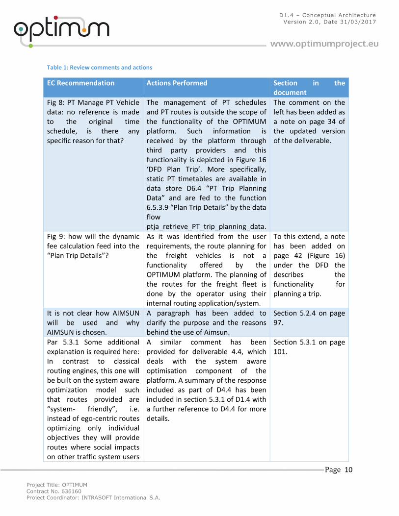
Table 1: Review comments and actions
EC Recommendation Actions Performed Section in the document
Fig 8: PT Manage PT Vehicle data: no reference is made to the original time schedule, is there any specific reason for that?
The management of PT schedules and PT routes is outside the scope of the functionality of the OPTIMUM platform. Such information is received by the platform through third party providers and this functionality is depicted in Figure 16 ‘DFD Plan Trip’. More specifically, static PT timetables are available in data store D6.4 “PT Trip Planning Data” and are fed to the function 6.5.3.9 “Plan Trip Details” by the data flow ptja_retrieve_PT_trip_planning_data.
The comment on the left has been added as a note on page 34 of the updated version of the deliverable.
Fig 9: how will the dynamic fee calculation feed into the “Plan Trip Details”?
As it was identified from the user requirements, the route planning for the freight vehicles is not a functionality offered by the OPTIMUM platform. The planning of the routes for the freight fleet is done by the operator using their internal routing application/system.
To this extend, a note has been added on page 42 (Figure 16) under the DFD the describes the functionality for planning a trip.
It is not clear how AIMSUN will be used and why AIMSUN is chosen.
A paragraph has been added to clarify the purpose and the reasons behind the use of Aimsun.
Section 5.2.4 on page 97.
Par 5.3.1 Some additional explanation is required here: In contrast to classical routing engines, this one will be built on the system aware optimization model such that routes provided are “system- friendly”, i.e. instead of ego-centric routes optimizing only individual objectives they will provide routes where social impacts on other traffic system users
A similar comment has been provided for deliverable 4.4, which deals with the system aware optimisation component of the platform. A summary of the response included as part of D4.4 has been included in section 5.3.1 of D1.4 with a further reference to D4.4 for more details.
Section 5.3.1 on page 101.
Project Title: OPTIMUM
Contract No. 636160 Project Coordinator: INTRASOFT International S.A.
Page 11
D1.4 – Conceptual Architecture
Version 2.0, Date 31/03/2017
will be minimised. Be aware that this requires transparency and explanation towards the end-users...
Chapter 7 Conceptual Architecture Validations only covers the mapping of the services on the architecture components. It looks like everything is covered without need for improvement/adjustments? Too good to be true??
As it is depicted in Figure 1 of the deliverable, the approach followed for the definition of the conceptual architecture was a mixture of top-down and bottom-up approaches. The processes/actions used for the validation of the conceptual architecture were derived from the user requirements, which were in turn used for the definition of the use cases (top-down). Concurrently, the functionality of the different components was initially defined using the findings from the state-of-the-art review and was adjusted to meet any requirements that were not originally taken into consideration (bottom-up). Therefore, the mapping of all processes/actions from the use cases to system components was expected, since it was the intention of the conceptual design to meet all the requirements (of high priority) identified by the users. Furthermore, this initial conceptual architecture was further refined, based on necessary improvements on technical level, to form the system architecture as part of WP6. Finally, it is envisaged that additional improvements for the functionality of the platform will be identified throughout the pilots and, based on their importance, a number of such improvements will be implemented
To clarify this issue, a paragraph has been added in the introductory section of Chapter 7, on page 123.
Project Title: OPTIMUM
Contract No. 636160 Project Coordinator: INTRASOFT International S.A.
Page 12
D1.4 – Conceptual Architecture
Version 2.0, Date 31/03/2017
as part of the second round of development of the individual components.
Project Title: OPTIMUM
Contract No. 636160 Project Coordinator: INTRASOFT International S.A.
Page 13
D1.4 – Conceptual Architecture
Version 2.0, Date 31/03/2017
1 Introduction The purpose of this report is to define the conceptual architecture of the OPTIMUM platform.
The proposed architecture was developed using the findings from the user requirements
analysis (D1.2) and use case and data sources descriptions (D1.3). The functional specification
of the platform was designed using the European ITS Framework Architecture1 (FRAME
Architecture), which was developed to support the design of interoperable ITS across Europe.
The OPTIMUM conceptual architecture has been defined in a layered structure using the
Observe, Orient, Decide and Act (OODA) paradigm that underpins the operation of the
OPTIMUM platform. This decomposition allows the discretisation of functions and components
into a layered architecture with each layer being responsible for the provision of specific
services, allowing for better maintainability, extensibility and scalability. A brief description of
each layer of the architecture is as follows:
Observe - This layer focuses mainly on the collection, cleaning and fusion of big-data from
various sources. Such sources include historical and real-time data from infrastructure-based
ITS, on-board units, transport operators, air-quality and weather stations, together with
traveller behavioural information and crowdsourcing data. OPTIMUM will provide the
necessary data infrastructure in order to handle big amounts of ITS related data characterized
by frequent update rates. Such data production is being driven by:
individuals and their increased use of media (social networks).
novel types of sensors and communication capabilities in vehicle and the traffic
infrastructure.
application of modern Information and Communication Technologies (ICT) (Cloud
computing, Internet of Things (IoT), etc.).
increased availability of modalities (including public transportation, car sharing, car2go)
and related information (such as publicly available time schedules) all related to the
proliferation of internet connected devices and systems.
Data sets grow in size because they are being gathered increasingly by ubiquitous information
sensing mobile devices, aerial sensory technologies (remote sensing), software logs, cameras,
microphones, radio-frequency identification readers, and wireless sensor networks. There has
also been acceleration in the proportion of machine-generated and unstructured data (photos,
videos, social media feeds, etc.).
The Observe layer encompasses a scalable storage engine and a Publish-Subscribe Middleware
(PubSubM) that realizes an Event Driven Architecture (EDA) and supports Service Oriented
1 http://frame-online.eu
Project Title: OPTIMUM
Contract No. 636160 Project Coordinator: INTRASOFT International S.A.
Page 14
D1.4 – Conceptual Architecture
Version 2.0, Date 31/03/2017
Architecture (SOA) and infrastructure for components and end user services. Low-level data
manipulation such as opinion mining, natural language processing and sentinel analysis is part
of the Observe layer. Additionally, a mobile semantic processing engine that enables complex
real-time processing close to the edge of the network (mobile devices) forms part of the layer.
Orient – This layer acts as a data transformer and enricher using complex real-time processing
and online stream analytics techniques that support the forecasting-related services and
predictive capabilities of the platform. The Orient layer will be built using an ITS integration
approach for the provision of components for processing and enriching raw data from the
Observe layer.
Services for Situation Assessment will enable the generation of real-time, data-driven
predictions, as well as the discovery of unusual situations, based on events published through
the EDA or retrieved from storage. Novel prediction services will be realized as intelligent
services on the top of Probabilistic Stream Processing (PSP), a theory implemented in Qminer2.
A Goal-driven Complex Event Processing component will have the role of dynamic definition
and detection of complex events and reasoning over events, supplied by the event storage.
Traffic forecasting will be offered through the integration of machine learning, statistical
modelling and simulation techniques in order to provide short and long term forecasts for the
network. The prediction of travellers’ behaviour will be based on the profiling of individual
travellers, using theories of individual choice behaviour analysis.
Decide - The Decide layer will provide novel system-optimal multi-modal routing algorithms
and innovative charging models. More specifically, the Routing & Navigation algorithms will be
based on real-time multi-modal information providing real-time time dependent shortest path
algorithms for one-mode trips (e.g. auto only) and real-time time dependent shortest path
algorithms for intermodal trips (e.g. auto plus bus and/or train). The advancements in complex
event processing, predictive analytics and forecasting envisaged as part of OPTIMUM project
will support the above stated systems and algorithm for the realisation of a “true” multi-modal
information system. Due to the impact of freight vehicles in the level of service of highway and
urban networks, as well as the wear and tear of road infrastructure, dedicated dynamic
charging models will be developed as part of this layer. This will offer variable tolls for freight
vehicles based on attributes, such as distance to be travelled, vehicle classification (size and
emission outputs), maintenance costs, cargo utilisation, traffic information and others.
Pro-Act - Smart services for Pro-Acting will generate, properly format, filter and deliver
actionable information to the end users. An inclusive and rich user profile will be the basis for
information personalization and recommendations. The profile will integrate implicit and
explicit user preferences captured from information acquired through interactions with the
2 http://quintelligence.com/qminer
Project Title: OPTIMUM
Contract No. 636160 Project Coordinator: INTRASOFT International S.A.
Page 15
D1.4 – Conceptual Architecture
Version 2.0, Date 31/03/2017
OPTIMUM system and inferred using machine learning techniques, by observing travel
behaviours and preferred transportation means as well as stated environmental and
behavioural attitudes. A repository of personalized persuasive strategies will drive the form
and content of information delivered to end-users. The personalisation & recommendation
services, aim at achieving the proper mixture of persuasiveness and user comfort, reasoning
upon factors affecting the extent to which a recommendation influences its receiver, such as
the scope of the recommendations, the form and content of the message, the receiver and
her/his characteristics and the contextual factors. Big Data fusion will allow the Pro-Act layer of
OPTIMUM to offer personalized and proactive multimodal travel advice taking into account the
characteristics, attitudes, perceptions, preferences, and constraints of each individual while
overcoming the limitation of existing applications, which are limited to reactive services.
Information to be delivered includes: information stored in the system and combined with
interesting events raised by the sensing services (e.g. detected changes in public transportation
time plans); information predicted by the situation assessment services (e.g. imminent traffic
incidents); information provided by the guidance and control components (e.g. optimal routes
to follow, suggestions for modal shifts and impact of actions). The proposed framework of
personalized transportation information delivery will encompass proactive recommenders that
take into account the travellers context in order to assist citizens in making green decisions
while commuting, or driving.
1.1 Structure of the Deliverable The deliverable has been divided into the following chapters:
Chapter 2, describes the methodological approach that was adopted for the
development of the conceptual architecture. It describes the individual steps that were
undertaken and how these steps were integrated into a coherent sequence of activities.
In cases, it goes beyond pure methodological descriptions and presents outputs of
activities in order to link the conceptual architecture with outcomes resulted in Tasks
1.2 and 1.3 of the project.
Chapter 3, presents the OPTIMUM functional viewpoint, based on the FRAME ITS
architecture, that is envisaged to be used as guidance for the implementation of the
components. The functional viewpoint is composed of a series of Data Flow Diagrams
(DFDs) that encompass low level functions, data stores, terminators/actors and data-
flows (customised when necessary) as described in the European ITS architecture.
Chapter 4, contains the high-level physical specification of the OPTIMUM platform. A
brief description of each component is presented, as well as, an integrated components
diagram that illustrates the interfaces and interconnections of the different elements of
the platform. Furthermore, the chapter includes a mapping of the functionality
described in chapter 3 with the different components of the OPTIMUM platform.
Project Title: OPTIMUM
Contract No. 636160 Project Coordinator: INTRASOFT International S.A.
Page 16
D1.4 – Conceptual Architecture
Version 2.0, Date 31/03/2017
Chapter 5, comprises detailed specifications for each component of the OPTIMUM
platform. Each individual specification offers a description and explains the purpose of
the component, describes the interfaces that the component will implement, or
consume and illustrates a subcomponent diagram to detail the internal parts of the
component.
Chapter 6, provides a description of the data security approach that is proposed for the
OPTIMUM platform. Aspects such as data encryption, data integrity and access
authentication are included. In addition, an abstract component diagram that depicts
how the proposed data security framework will be implemented as part of the platform
is presented.
The deliverable concludes with Chapter 7, that validates the proposed conceptual
architecture against the processes identified in the use cases that were developed as
part of Task 1.3. Each use case process is mapped to a platform’s component in order to
ensure that the functionality described can be realised by the platform.
Project Title: OPTIMUM
Contract No. 636160 Project Coordinator: INTRASOFT International S.A.
Page 17
D1.4 – Conceptual Architecture
Version 2.0, Date 31/03/2017
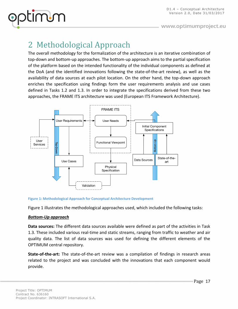
2 Methodological Approach The overall methodology for the formalization of the architecture is an iterative combination of
top-down and bottom-up approaches. The bottom-up approach aims to the partial specification
of the platform based on the intended functionality of the individual components as defined at
the DoA (and the identified innovations following the state-of-the-art review), as well as the
availability of data sources at each pilot location. On the other hand, the top-down approach
enriches the specification using findings form the user requirements analysis and use cases
defined in Tasks 1.2 and 1.3. In order to integrate the specifications derived from these two
approaches, the FRAME ITS architecture was used (European ITS Framework Architecture).
Figure 1: Methodological Approach for Conceptual Architecture Development
Figure 1 illustrates the methodological approaches used, which included the following tasks:
Bottom-Up approach
Data sources: The different data sources available were defined as part of the activities in Task
1.3. These included various real-time and static streams, ranging from traffic to weather and air
quality data. The list of data sources was used for defining the different elements of the
OPTIMUM central repository.
State-of-the-art: The state-of-the-art review was a compilation of findings in research areas
related to the project and was concluded with the innovations that each component would
provide.
Project Title: OPTIMUM
Contract No. 636160 Project Coordinator: INTRASOFT International S.A.
Page 18
D1.4 – Conceptual Architecture
Version 2.0, Date 31/03/2017
Initial Component Specifications: The above tasks led to the development of the initial
specifications for the individual components of the platform. The template attached as
Appendix 1 was used, with primary aim to ensure the availability of data sources that each
component requires in order to function. As part of this activity, input and output data sources
for each component were identified and an overall initial conceptual architecture was drawn
up.
Top-Down approach
User Requirements: The user requirements for the OPTIMUM platform were defined through
questionnaire and interview studies that covered the different pilot sites and type of services at
each site. These studies were informed by the user services described in the DoA. A detailed
analysis of the requirements was presented in D1.2 with a summarized version of the main
findings as follows:
For pilot case 1 (Proactive Improvement of Transport Systems Quality and Efficiency),
availability of information related to travel times and public transport operations was
identified as highly important. In addition, it was revealed that such information should
be provided at different stages of a trip (planning, preparation, implementation) and
therefore, forecasting functionality (short and long term) should be embedded in the
OPTIMUM platform. Finally, for the on-trip stage of a multimodal trip, the need for real
time information about travel times, incidents, conditions at interchanges, as well as
navigation instructions was highlighted.
For pilot case 2 (Proactive Charging Schemes for Freight Transport), the main
functionality required by the OPTIMUM platform revolved around the provision of
dynamic toll prices for freight transport operations. The toll prices should be calculated
based on a number of criteria, including predicted traffic flows, heavy vehicle flows,
level of service and projected environmental emissions.
For pilot case 3 (Integrated Car2x Communication Platform), provision of information
services for optimal fuel consumption and minimisation of CO2 emissions per trip were
ranked highly among the respondents. In addition, the provision of real-time
information, supported by short-term forecasts about the status of the transport
network, was identified as a need for the OPTIMUM platform. Content of interest for
such information included shortest travel times, traffic conditions, traffic incidents
information and sudden changes of average speeds.
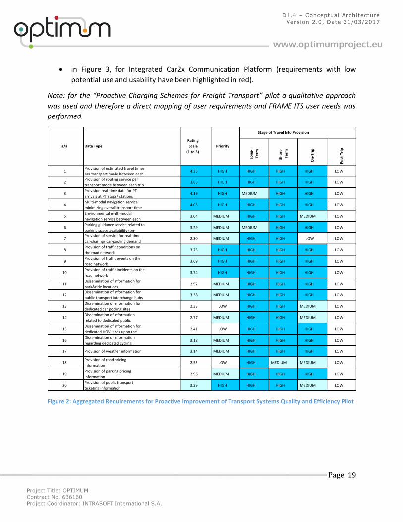
Aggregated versions of quantitative user requirements can be seen:
In Figure 2, for pilot case 1 (an aggregation of the requirements from all pilot cities) the
information requirements per stage of the trip are presented.
Project Title: OPTIMUM
Contract No. 636160 Project Coordinator: INTRASOFT International S.A.
Page 19
D1.4 – Conceptual Architecture
Version 2.0, Date 31/03/2017
in Figure 3, for Integrated Car2x Communication Platform (requirements with low
potential use and usability have been highlighted in red).
Note: for the “Proactive Charging Schemes for Freight Transport” pilot a qualitative approach
was used and therefore a direct mapping of user requirements and FRAME ITS user needs was
performed.
Figure 2: Aggregated Requirements for Proactive Improvement of Transport Systems Quality and Efficiency Pilot
Long-
Term
Short-
Term
On-Trip
Post-Trip
1Provisionofestimatedtraveltimes
pertransportmodebetweeneach4.35 HIGH HIGH HIGH HIGH LOW
2Provisionofroutingserviceper
transportmodebetweeneachtrip3.85 HIGH HIGH HIGH HIGH LOW
3Provisionreal-timedataforPT
arrivalsatPTstops/stations4.19 HIGH MEDIUM HIGH HIGH LOW
4Multi-modalnavigationservice
minimizingoveralltransporttime4.05 HIGH HIGH HIGH HIGH LOW
5Environmentalmulti-modal
navigationservicebetweeneach3.04 MEDIUM HIGH HIGH MEDIUM LOW
6Parkingguidanceservicerelatedto
parkingspaceavailability(on-3.29 MEDIUM MEDIUM HIGH HIGH LOW
7Provisionofserviceforreal-time
car-sharing/car-poolingdemand2.30 MEDIUM HIGH HIGH LOW LOW
8Provisionoftrafficconditionson
theroadnetwork3.73 HIGH HIGH HIGH HIGH LOW
9Provisionoftrafficeventsonthe
roadnetwork3.69 HIGH HIGH HIGH HIGH LOW
10Provisionoftrafficincidentsonthe
roadnetwork3.74 HIGH HIGH HIGH HIGH LOW
11Disseminationofinformationfor
park&ridelocations2.92 MEDIUM HIGH HIGH HIGH LOW
12Disseminationofinformationfor
publictransportinterchangehubs3.38 MEDIUM HIGH HIGH HIGH LOW
13Disseminationofinformationfor
dedicatedcarpoolingsites2.33 LOW HIGH HIGH MEDIUM LOW
14Disseminationofinformation
relatedtodedicatedpublic2.77 MEDIUM HIGH HIGH MEDIUM LOW
15Disseminationofinformationfor
dedicatedHOVlanesuponthe2.41 LOW HIGH HIGH HIGH LOW
16Disseminationofinformation
regardingdedicatedcycling3.18 MEDIUM HIGH HIGH HIGH LOW
17 Provisionofweatherinformation 3.14 MEDIUM HIGH HIGH HIGH LOW
18Provisionofroadpricing
information2.53 LOW HIGH MEDIUM MEDIUM LOW
19Provisionofparkingpricing
information2.96 MEDIUM HIGH HIGH HIGH LOW
20Provisionofpublictransport
ticketinginformation3.39 HIGH HIGH HIGH MEDIUM LOW
a/a DataType
Rating
Scale
(1to5)
Priority
StageofTravelInfoProvision
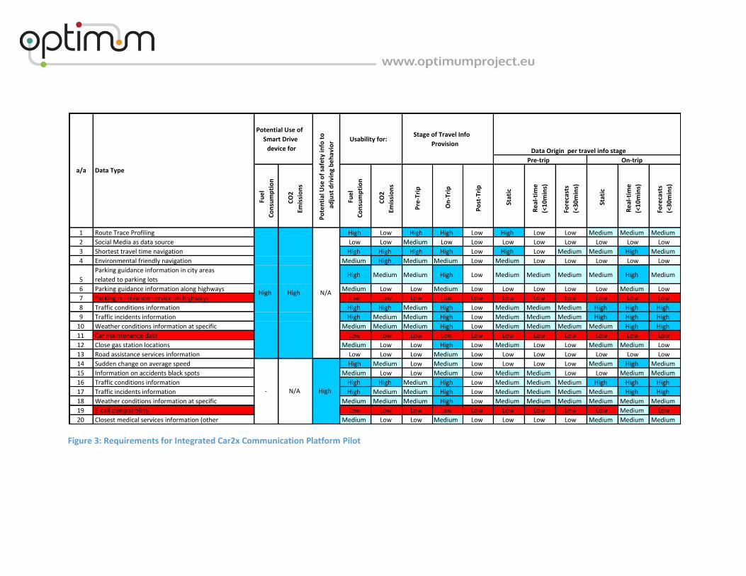
Figure 3: Requirements for Integrated Car2x Communication Platform Pilot
Fuel
Consumption
CO2
Emissions
Fuel
Consumption
CO2
Emissions
Pre-Trip
On-Trip
Post-Trip
Static
Real-tim
e
(<10mins)
Forecasts
(<30mins)
Static
Real-tim
e
(<10mins)
Forecasts
(<30mins)
1 RouteTraceProfiling High Low High High Low High Low Low Medium Medium Medium
2 SocialMediaasdatasource Low Low Medium Low Low Low Low Low Low Low Low
3 Shortesttraveltimenavigation High High High High Low High Low Medium Medium High Medium
4 Environmentalfriendlynavigation Medium High Medium Medium Low Medium Low Low Low Low Low
5
Parkingguidanceinformationincityareas
relatedtoparkinglotsHigh Medium Medium High Low Medium Medium Medium Medium High Medium
6 Parkingguidanceinformationalonghighways Medium Low Low Medium Low Low Low Low Low Medium Low
7 Parkingreservationserviceonhighways Low Low Low Low Low Low Low Low Low Low Low
8 Trafficconditionsinformation High High Medium High Low Medium Medium Medium High High High
9 Trafficincidentsinformation High Medium Medium High Low Medium Medium Medium High High High
10 Weatherconditionsinformationatspecific Medium Medium Medium High Low Medium Medium Medium Medium High High
11 Carmaintenancedata Low Low Low Low Low Low Low Low Low Low Low
12 Closegasstationlocations Medium Low Low High Low Medium Low Low Medium Medium Low
13 Roadassistanceservicesinformation Low Low Low Medium Low Low Low Low Low Low Low
14 Suddenchangeonaveragespeed High Medium Low Medium Low Low Low Low Medium High Medium
15 Informationonaccidentsblackspots Medium Low Low Medium Low Medium Medium Low Low Medium Medium
16 Trafficconditionsinformation High High Medium High Low Medium Medium Medium High High High
17 Trafficincidentsinformation High Medium Medium High Low Medium Medium Medium Medium High High
18 Weatherconditionsinformationatspecific Medium Medium Medium High Low Medium Medium Medium Medium Medium Medium
19 E-callcompatibility Low Low Low Low Low Low Low Low Low Medium Low
20 Closestmedicalservicesinformation(other Medium Low Low Medium Low Low Low Low Medium Medium Medium
DataOriginpertravelinfostage
High
High High
PotentialUseof
SmartDrive
devicefor
PotentialUseofsafetyinfoto
adjustdrivingbehavior Usabilityfor:
Pre-trip On-trip
N/A
a/a DataType
StageofTravelInfo
Provision
N/A
-
Project Title: OPTIMUM
Contract No. 636160 Project Coordinator: INTRASOFT International S.A.
Page 21
D1.4 – Conceptual Architecture
Version 2.0, Date 31/03/2017
Use Cases: A number of use cases were developed as part of T1.3. These were aligned to the
user requirements and highlighted the offerings of the platform for each pilot. The use cases
defined high level process flows that describe interactions between the users and the platform,
as well as logical links between the different components of the platform.
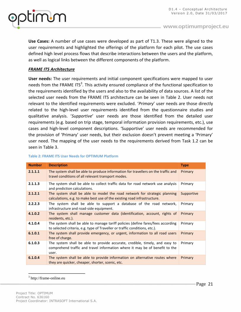
FRAME ITS Architecture
User needs: The user requirements and initial component specifications were mapped to user
needs from the FRAME ITS3. This activity ensured compliance of the functional specification to
the requirements identified by the users and also to the availability of data sources. A list of the
selected user needs from the FRAME ITS architecture can be seen in Table 2. User needs not
relevant to the identified requirements were excluded. ‘Primary’ user needs are those directly
related to the high-level user requirements identified from the questionnaire studies and
qualitative analysis. ‘Supportive’ user needs are those identified from the detailed user
requirements (e.g. based on trip stage, temporal information provision requirements, etc.), use
cases and high-level component descriptions. ‘Supportive’ user needs are recommended for
the provision of ‘Primary’ user needs, but their exclusion doesn’t prevent meeting a ‘Primary’
user need. The mapping of the user needs to the requirements derived from Task 1.2 can be
seen in Table 3.
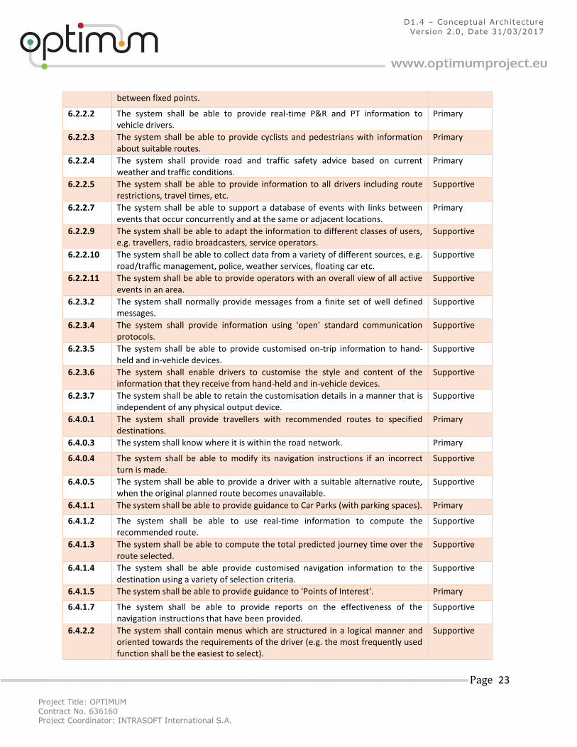
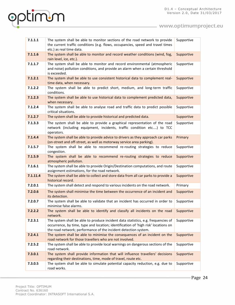
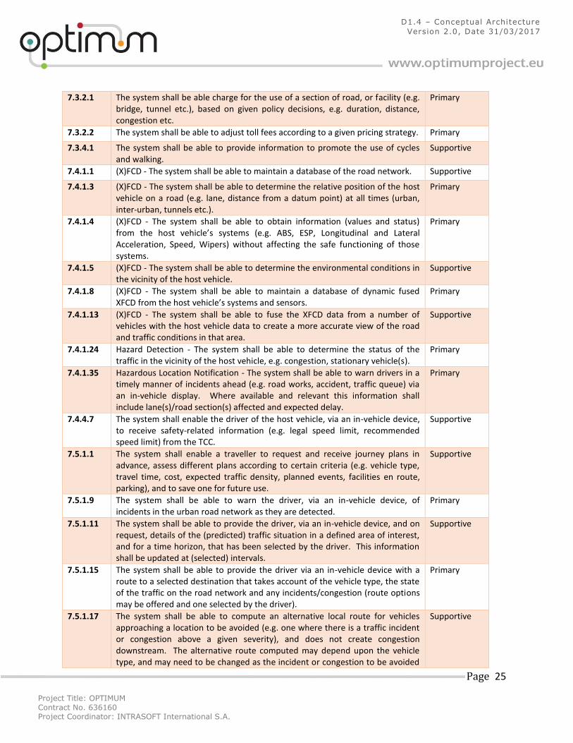
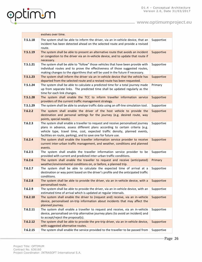
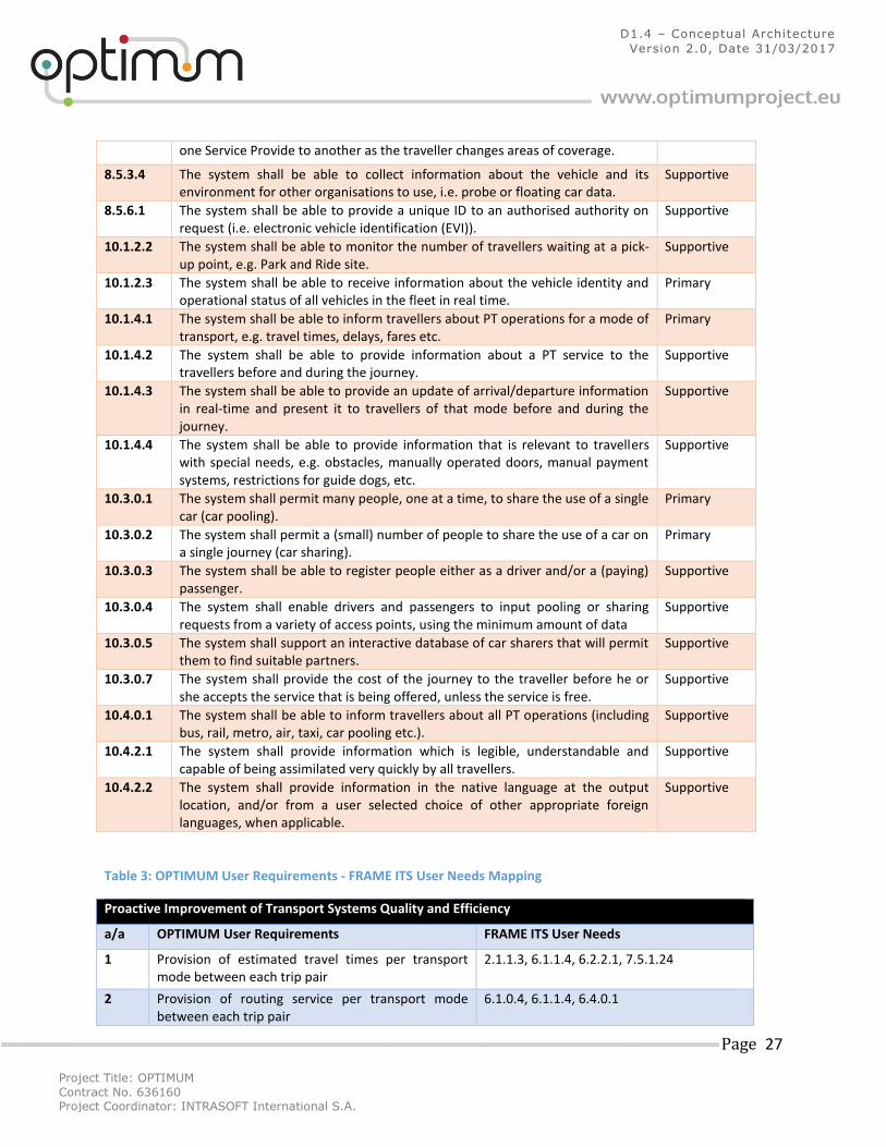
Table 2: FRAME ITS User Needs for OPTIMUM Platform
Number Description Type
2.1.1.1 The system shall be able to produce information for travellers on the traffic and travel conditions of all relevant transport modes.
Primary
2.1.1.3 The system shall be able to collect traffic data for road network use analysis and prediction calculations.
Primary
2.1.2.1 The system shall be able to model the road network for strategic planning calculations, e.g. to make best use of the existing road infrastructure.
Supportive
2.2.2.3 The system shall be able to support a database of the road network, infrastructure and road-side equipment.
Primary
4.1.0.2 The system shall manage customer data (identification, account, rights of residents, etc.).
Primary
4.1.0.4 The system shall be able to manage tariff policies (define fares/fees according to selected criteria, e.g. type of Traveller or traffic conditions, etc.).
Primary
6.1.0.1 The system shall provide emergency, or urgent, information to all road users free of charge.
Primary
6.1.0.3 The system shall be able to provide accurate, credible, timely, and easy to comprehend traffic and travel information where it may be of benefit to the user.
Primary
6.1.0.4 The system shall be able to provide information on alternative routes where they are quicker, cheaper, shorter, scenic, etc.
Primary
3 http://frame-online.eu
Project Title: OPTIMUM
Contract No. 636160 Project Coordinator: INTRASOFT International S.A.
Page 22
D1.4 – Conceptual Architecture
Version 2.0, Date 31/03/2017
6.1.0.5 The system shall enable travellers to plan their trip using their own travel criteria (modes of transport, time of departure/arrival, road selection criteria, etc.).
Supportive
6.1.0.6 The system shall enable travellers to plan their trip according to the needs of their disabilities.
Supportive
6.1.0.7 The system shall be able to provide information so that travellers may share a vehicle with others for all or part of a (multi-modal) journey.
Primary
6.1.1.4 The system shall be able to provide extensive multi-modal trip information, e.g. prices, fares, routes, forecast & current traffic situations, traffic control, demand mgt measures, local warnings, special events, weather conditions, hotels etc.
Primary
6.1.2.1 The system shall inform the User when changes occur to the criteria upon which the pre trip information had been given.
Supportive
6.1.2.2 The system shall be able to provide information on the cancellation of departures from an inter-modal interchange (e.g. railway station, an airport , a port or a coach station) due to the weather; strikes or other reasons.
Primary
6.1.2.3 The system shall be able to provide information to all drivers including route restrictions, travel times, etc.
Supportive
6.1.2.4 The system shall be able to support a database of events with links between events that occur concurrently and at the same or adjacent locations.
Primary
6.1.2.5 The system shall be able to analyse, process and retrieve data from different combinations of sources (including floating car).
Supportive
6.1.2.6 The system shall be able to provide road and traffic information adapted to different classes of users, e.g. travellers, radio broadcasters, service operators.
Supportive
6.1.2.7 The system shall provide information using graphical representation or text. Graphical form shall include the use of maps as well as text.
Supportive
6.1.2.8 The system shall provide information in the native language at the output location, and/or from a user selected choice of other appropriate foreign languages.
Supportive
6.1.2.10 The system shall be able to provide access information for those travellers with special needs (e.g. physical access, lifts, escalators, parking & toilets, nappy changing rooms, access for (guide) dogs, etc.) at relevant areas, e.g. transit areas.
Supportive
6.1.2.13 The system shall be able to provide information to travellers so as to influence their choice of destination and/or mode of travel, e.g. to protect the environment of a 'Point of Interest', or geographic area.
Supportive
6.2.0.4 The system shall provide traffic information to the traveller during his/her trip in a timely manner, and include travel conditions, accidents, special events, car park status, etc.
Primary
6.2.0.6 The system shall inform the User when changes occur to the criteria upon which the pre trip information had been given.
Supportive
6.2.0.7 The system shall be able to know where it is in the transport network, and hence provide the position of vehicle or person carrying it.
Primary
6.2.1.1 The system shall be able to provide alternative routes or mode-switch recommendations when it detects, or is informed, that problems have occurred on a mode.
Supportive
6.2.1.3 The system shall be able to provide information about other transport modes: e.g. location of P+R areas, PT timetable, etc.
Primary
6.2.2.1 The system shall be able to inform travellers on the current average travel time Primary
Project Title: OPTIMUM
Contract No. 636160 Project Coordinator: INTRASOFT International S.A.
Page 23
D1.4 – Conceptual Architecture
Version 2.0, Date 31/03/2017
between fixed points.
6.2.2.2 The system shall be able to provide real-time P&R and PT information to vehicle drivers.
Primary
6.2.2.3 The system shall be able to provide cyclists and pedestrians with information about suitable routes.
Primary
6.2.2.4 The system shall provide road and traffic safety advice based on current weather and traffic conditions.
Primary
6.2.2.5 The system shall be able to provide information to all drivers including route restrictions, travel times, etc.
Supportive
6.2.2.7 The system shall be able to support a database of events with links between events that occur concurrently and at the same or adjacent locations.
Primary
6.2.2.9 The system shall be able to adapt the information to different classes of users, e.g. travellers, radio broadcasters, service operators.
Supportive
6.2.2.10 The system shall be able to collect data from a variety of different sources, e.g. road/traffic management, police, weather services, floating car etc.
Supportive
6.2.2.11 The system shall be able to provide operators with an overall view of all active events in an area.
Supportive
6.2.3.2 The system shall normally provide messages from a finite set of well defined messages.
Supportive
6.2.3.4 The system shall provide information using 'open' standard communication protocols.
Supportive
6.2.3.5 The system shall be able to provide customised on-trip information to hand-held and in-vehicle devices.
Supportive
6.2.3.6 The system shall enable drivers to customise the style and content of the information that they receive from hand-held and in-vehicle devices.
Supportive
6.2.3.7 The system shall be able to retain the customisation details in a manner that is independent of any physical output device.
Supportive
6.4.0.1 The system shall provide travellers with recommended routes to specified destinations.
Primary
6.4.0.3 The system shall know where it is within the road network. Primary
6.4.0.4 The system shall be able to modify its navigation instructions if an incorrect turn is made.
Supportive
6.4.0.5 The system shall be able to provide a driver with a suitable alternative route, when the original planned route becomes unavailable.
Supportive
6.4.1.1 The system shall be able to provide guidance to Car Parks (with parking spaces). Primary
6.4.1.2 The system shall be able to use real-time information to compute the recommended route.
Supportive
6.4.1.3 The system shall be able to compute the total predicted journey time over the route selected.
Supportive
6.4.1.4 The system shall be able provide customised navigation information to the destination using a variety of selection criteria.
Supportive
6.4.1.5 The system shall be able to provide guidance to 'Points of Interest'. Primary
6.4.1.7 The system shall be able to provide reports on the effectiveness of the navigation instructions that have been provided.
Supportive
6.4.2.2 The system shall contain menus which are structured in a logical manner and oriented towards the requirements of the driver (e.g. the most frequently used function shall be the easiest to select).
Supportive
Project Title: OPTIMUM
Contract No. 636160 Project Coordinator: INTRASOFT International S.A.
Page 24
D1.4 – Conceptual Architecture
Version 2.0, Date 31/03/2017
7.1.1.1 The system shall be able to monitor sections of the road network to provide the current traffic conditions (e.g. flows, occupancies, speed and travel times etc.) as real time data.
Supportive
7.1.1.6 The system shall be able to monitor and record weather conditions (wind, fog, rain level, ice, etc.).
Supportive
7.1.1.7 The system shall be able to monitor and record environmental (atmospheric and noise) pollution conditions, and provide an alarm when a certain threshold is exceeded.
Supportive
7.1.2.1 The system shall be able to use consistent historical data to complement real-time data, when necessary.
Supportive
7.1.2.2 The system shall be able to predict short, medium, and long-term traffic conditions.
Supportive
7.1.2.3 The system shall be able to use historical data to complement predicted data, when necessary.
Supportive
7.1.2.4 The system shall be able to analyse road and traffic data to predict possible critical situations.
Supportive
7.1.2.7 The system shall be able to provide historical and predicted data. Supportive
7.1.3.3 The system shall be able to provide a graphical representation of the road network (including equipment, incidents, traffic condition etc....) to TCC operators.
Supportive
7.1.4.4 The system shall be able to provide advice to drivers as they approach car parks (on-street and off-street, as well as motorway service area parking).
Primary
7.1.5.7 The system shall be able to recommend re-routing strategies to reduce congestion.
Supportive
7.1.5.9 The system shall be able to recommend re-routing strategies to reduce atmospheric pollution.
Supportive
7.1.6.1 The system shall be able to provide Origin/Destination computations, and route assignment estimations, for the road network.
Supportive
7.1.11.4 The system shall be able to collect and store data from all car parks to provide a historical record.
Supportive
7.2.0.1 The system shall detect and respond to various incidents on the road network. Primary
7.2.0.6 The system shall minimise the time between the occurrence of an incident and its detection.
Supportive
7.2.0.7 The system shall be able to validate that an incident has occurred in order to minimise false alarms.
Supportive
7.2.2.2 The system shall be able to identify and classify all incidents on the road network.
Supportive
7.2.3.1 The system shall be able to produce incident data statistics, e.g. frequencies of occurrence, by time, type and location; identification of 'high risk' locations on the road network; performance of the incident detection system.
Supportive
7.2.4.1 The system shall be able to minimise the consequences of an incident on the road network for those travellers who are not involved.
Supportive
7.2.5.2 The system shall be able to provide local warnings on dangerous sections of the road network.
Supportive
7.3.0.1 The system shall provide information that will influence travellers' decisions regarding their destinations, time, mode of travel, route etc.
Supportive
7.3.0.5 The system shall be able to simulate potential capacity reduction, e.g. due to road works.
Supportive
Project Title: OPTIMUM
Contract No. 636160 Project Coordinator: INTRASOFT International S.A.
Page 25
D1.4 – Conceptual Architecture
Version 2.0, Date 31/03/2017
7.3.2.1 The system shall be able charge for the use of a section of road, or facility (e.g. bridge, tunnel etc.), based on given policy decisions, e.g. duration, distance, congestion etc.
Primary
7.3.2.2 The system shall be able to adjust toll fees according to a given pricing strategy. Primary
7.3.4.1 The system shall be able to provide information to promote the use of cycles and walking.
Supportive
7.4.1.1 (X)FCD - The system shall be able to maintain a database of the road network. Supportive
7.4.1.3 (X)FCD - The system shall be able to determine the relative position of the host vehicle on a road (e.g. lane, distance from a datum point) at all times (urban, inter-urban, tunnels etc.).
Primary
7.4.1.4 (X)FCD - The system shall be able to obtain information (values and status) from the host vehicle’s systems (e.g. ABS, ESP, Longitudinal and Lateral Acceleration, Speed, Wipers) without affecting the safe functioning of those systems.
Primary
7.4.1.5 (X)FCD - The system shall be able to determine the environmental conditions in the vicinity of the host vehicle.
Supportive
7.4.1.8 (X)FCD - The system shall be able to maintain a database of dynamic fused XFCD from the host vehicle’s systems and sensors.
Primary
7.4.1.13 (X)FCD - The system shall be able to fuse the XFCD data from a number of vehicles with the host vehicle data to create a more accurate view of the road and traffic conditions in that area.
Supportive
7.4.1.24 Hazard Detection - The system shall be able to determine the status of the traffic in the vicinity of the host vehicle, e.g. congestion, stationary vehicle(s).
Primary
7.4.1.35 Hazardous Location Notification - The system shall be able to warn drivers in a timely manner of incidents ahead (e.g. road works, accident, traffic queue) via an in-vehicle display. Where available and relevant this information shall include lane(s)/road section(s) affected and expected delay.
Primary
7.4.4.7 The system shall enable the driver of the host vehicle, via an in-vehicle device, to receive safety-related information (e.g. legal speed limit, recommended speed limit) from the TCC.
Supportive
7.5.1.1 The system shall enable a traveller to request and receive journey plans in advance, assess different plans according to certain criteria (e.g. vehicle type, travel time, cost, expected traffic density, planned events, facilities en route, parking), and to save one for future use.
Supportive
7.5.1.9 The system shall be able to warn the driver, via an in-vehicle device, of incidents in the urban road network as they are detected.
Primary
7.5.1.11 The system shall be able to provide the driver, via an in-vehicle device, and on request, details of the (predicted) traffic situation in a defined area of interest, and for a time horizon, that has been selected by the driver. This information shall be updated at (selected) intervals.
Supportive
7.5.1.15 The system shall be able to provide the driver via an in-vehicle device with a route to a selected destination that takes account of the vehicle type, the state of the traffic on the road network and any incidents/congestion (route options may be offered and one selected by the driver).
Primary
7.5.1.17 The system shall be able to compute an alternative local route for vehicles approaching a location to be avoided (e.g. one where there is a traffic incident or congestion above a given severity), and does not create congestion downstream. The alternative route computed may depend upon the vehicle type, and may need to be changed as the incident or congestion to be avoided
Supportive
Project Title: OPTIMUM
Contract No. 636160 Project Coordinator: INTRASOFT International S.A.
Page 26
D1.4 – Conceptual Architecture
Version 2.0, Date 31/03/2017
evolves over time.
7.5.1.18 The system shall be able to inform the driver, via an in-vehicle device, that an incident has been detected ahead on the selected route and provide a revised route.
Supportive
7.5.1.19 The system shall be able to present an alternative route that avoids an incident or congestion to the driver via an in-vehicle device, and to update that route if necessary.
Supportive
7.5.1.21 The system shall be able to “follow” those vehicles that have been provide with individual routes and to prove the effectiveness of those suggested routes, making changes to the algorithms that will be used in the future if necessary.
Supportive
7.5.1.23 The system shall inform the driver via an in-vehicle device that the vehicle has departed from the selected route and a revised route has been requested.
Supportive
7.5.1.24 The system shall be able to calculate a predicted time for a total journey made up from separate links. The predicted time shall be updated regularly as the time for each link changes.
Primary
7.5.1.28 The system shall enable the TCC to inform traveller information service providers of the current traffic management strategy.
Supportive
7.5.1.29 The system shall be able to analyse traffic data using an off-line simulation tool. Supportive
7.6.2.2 The system shall enable the driver of the host vehicle to provide the destination and personal settings for the journey (e.g. desired route, way points, special needs).
Supportive
7.6.2.3 The system shall enable a traveller to request and receive personalised journey plans in advance, assess different plans according to certain criteria (e.g. vehicle type, travel time, cost, expected traffic density, planned events, facilities en route, parking), and to save one for future use.
Supportive
7.6.2.4 The system shall enable the traveller information service provider to receive current inter-urban traffic management, and weather, conditions and planned events.
Supportive
7.6.2.5 The system shall enable the traveller information service provider to be provided with current and predicted inter-urban traffic conditions.
Supportive
7.6.2.6 The system shall enable the traveller to request and receive (anticipated) weather/environmental conditions on, or before, a planned trip.
Primary
7.6.2.7 The system shall be able to calculate the expected time of arrival at a destination or way point based on the driver’s profile and the anticipated traffic conditions.
Supportive
7.6.2.8 The system shall be able to provide the driver, via an in-vehicle device, with a personalised route.
Supportive
7.6.2.9 The system shall be able to provide the driver, via an in-vehicle device, with an estimated time of arrival which is updated at regular intervals.
Supportive
7.6.2.10 The system shall enable the driver to (request and) receive, via an in-vehicle device, personalised on-trip information about incidents that may affect the planned journey.
Supportive
7.6.2.11 The system shall enable a traveller to request and receive, via an in-vehicle device, personalised on-trip alternative journey plans (to avoid an incident) and to accept/reject the proposal(s).
Supportive
7.6.2.12 The system shall be able to provide the pre-trip driver, via an in-vehicle device, with suggested alternative routes.
Supportive
7.6.2.15 The system shall enable the service provided to the traveller to be passed from Supportive
Project Title: OPTIMUM
Contract No. 636160 Project Coordinator: INTRASOFT International S.A.
Page 27
D1.4 – Conceptual Architecture
Version 2.0, Date 31/03/2017
one Service Provide to another as the traveller changes areas of coverage.
8.5.3.4 The system shall be able to collect information about the vehicle and its environment for other organisations to use, i.e. probe or floating car data.
Supportive
8.5.6.1 The system shall be able to provide a unique ID to an authorised authority on request (i.e. electronic vehicle identification (EVI)).
Supportive
10.1.2.2 The system shall be able to monitor the number of travellers waiting at a pick-up point, e.g. Park and Ride site.
Supportive
10.1.2.3 The system shall be able to receive information about the vehicle identity and operational status of all vehicles in the fleet in real time.
Primary
10.1.4.1 The system shall be able to inform travellers about PT operations for a mode of transport, e.g. travel times, delays, fares etc.
Primary
10.1.4.2 The system shall be able to provide information about a PT service to the travellers before and during the journey.
Supportive
10.1.4.3 The system shall be able to provide an update of arrival/departure information in real-time and present it to travellers of that mode before and during the journey.
Supportive
10.1.4.4 The system shall be able to provide information that is relevant to travellers with special needs, e.g. obstacles, manually operated doors, manual payment systems, restrictions for guide dogs, etc.
Supportive
10.3.0.1 The system shall permit many people, one at a time, to share the use of a single car (car pooling).
Primary
10.3.0.2 The system shall permit a (small) number of people to share the use of a car on a single journey (car sharing).
Primary
10.3.0.3 The system shall be able to register people either as a driver and/or a (paying) passenger.
Supportive
10.3.0.4 The system shall enable drivers and passengers to input pooling or sharing requests from a variety of access points, using the minimum amount of data
Supportive
10.3.0.5 The system shall support an interactive database of car sharers that will permit them to find suitable partners.
Supportive
10.3.0.7 The system shall provide the cost of the journey to the traveller before he or she accepts the service that is being offered, unless the service is free.
Supportive
10.4.0.1 The system shall be able to inform travellers about all PT operations (including bus, rail, metro, air, taxi, car pooling etc.).
Supportive
10.4.2.1 The system shall provide information which is legible, understandable and capable of being assimilated very quickly by all travellers.
Supportive
10.4.2.2 The system shall provide information in the native language at the output location, and/or from a user selected choice of other appropriate foreign languages, when applicable.
Supportive
Table 3: OPTIMUM User Requirements - FRAME ITS User Needs Mapping
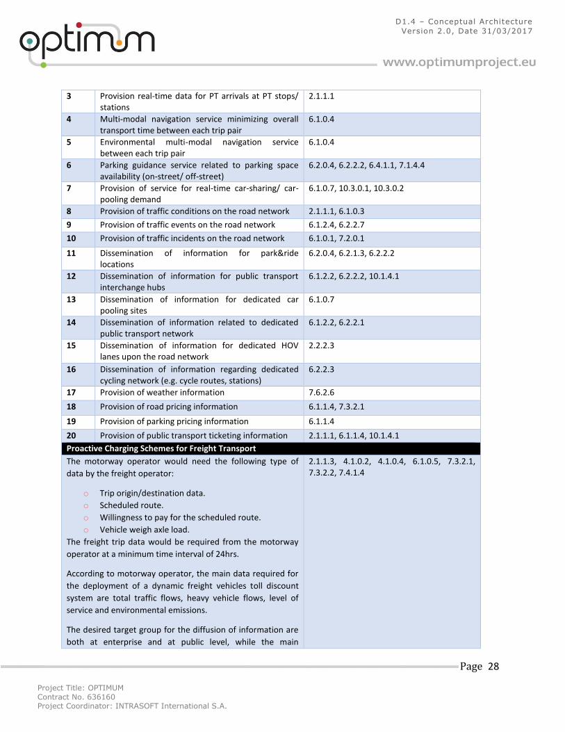
Proactive Improvement of Transport Systems Quality and Efficiency
a/a OPTIMUM User Requirements FRAME ITS User Needs
1 Provision of estimated travel times per transport mode between each trip pair
2.1.1.3, 6.1.1.4, 6.2.2.1, 7.5.1.24
2 Provision of routing service per transport mode between each trip pair
6.1.0.4, 6.1.1.4, 6.4.0.1
Project Title: OPTIMUM
Contract No. 636160 Project Coordinator: INTRASOFT International S.A.
Page 28
D1.4 – Conceptual Architecture
Version 2.0, Date 31/03/2017
3 Provision real-time data for PT arrivals at PT stops/ stations
2.1.1.1
4 Multi-modal navigation service minimizing overall transport time between each trip pair
6.1.0.4
5 Environmental multi-modal navigation service between each trip pair
6.1.0.4
6 Parking guidance service related to parking space availability (on-street/ off-street)
6.2.0.4, 6.2.2.2, 6.4.1.1, 7.1.4.4
7 Provision of service for real-time car-sharing/ car-pooling demand
6.1.0.7, 10.3.0.1, 10.3.0.2
8 Provision of traffic conditions on the road network 2.1.1.1, 6.1.0.3
9 Provision of traffic events on the road network 6.1.2.4, 6.2.2.7
10 Provision of traffic incidents on the road network 6.1.0.1, 7.2.0.1
11 Dissemination of information for park&ride locations
6.2.0.4, 6.2.1.3, 6.2.2.2
12 Dissemination of information for public transport interchange hubs
6.1.2.2, 6.2.2.2, 10.1.4.1
13 Dissemination of information for dedicated car pooling sites
6.1.0.7
14 Dissemination of information related to dedicated public transport network
6.1.2.2, 6.2.2.1
15 Dissemination of information for dedicated HOV lanes upon the road network
2.2.2.3
16 Dissemination of information regarding dedicated cycling network (e.g. cycle routes, stations)
6.2.2.3
17 Provision of weather information 7.6.2.6
18 Provision of road pricing information 6.1.1.4, 7.3.2.1
19 Provision of parking pricing information 6.1.1.4
20 Provision of public transport ticketing information 2.1.1.1, 6.1.1.4, 10.1.4.1
Proactive Charging Schemes for Freight Transport
The motorway operator would need the following type of
data by the freight operator:
o Trip origin/destination data.
o Scheduled route.
o Willingness to pay for the scheduled route.
o Vehicle weigh axle load.
The freight trip data would be required from the motorway
operator at a minimum time interval of 24hrs.
According to motorway operator, the main data required for
the deployment of a dynamic freight vehicles toll discount
system are total traffic flows, heavy vehicle flows, level of
service and environmental emissions.
The desired target group for the diffusion of information are
both at enterprise and at public level, while the main
2.1.1.3, 4.1.0.2, 4.1.0.4, 6.1.0.5, 7.3.2.1, 7.3.2.2, 7.4.1.4
Project Title: OPTIMUM
Contract No. 636160 Project Coordinator: INTRASOFT International S.A.
Page 29
D1.4 – Conceptual Architecture
Version 2.0, Date 31/03/2017
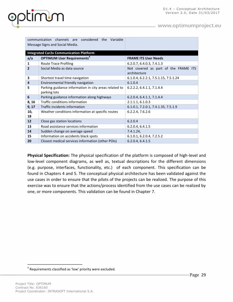
communication channels are considered the Variable
Message Signs and Social Media.
Integrated Car2x Communication Platform
a/a OPTIMUM User Requirements4 FRAME ITS User Needs
1 Route Trace Profiling 6.2.0.7, 6.4.0.3, 7.4.1.3
2 Social Media as data source Not covered as part of the FRAME ITS architecture
3 Shortest travel time navigation 6.1.0.4, 6.2.2.1, 7.5.1.15, 7.5.1.24
4 Environmental friendly navigation 6.1.0.4
5 Parking guidance information in city areas related to parking lots
6.2.2.2, 6.4.1.1, 7.1.4.4
6 Parking guidance information along highways 6.2.0.4, 6.4.1.1, 7.1.4.4
8, 16 Traffic conditions information 2.1.1.1, 6.1.0.3
9, 17 Traffic incidents information 6.1.0.1, 7.2.0.1, 7.4.1.35, 7.5.1.9
10, 18
Weather conditions information at specific routes 6.2.2.4, 7.6.2.6
12 Close gas station locations 6.2.0.4
13 Road assistance services information 6.2.0.4, 6.4.1.5
14 Sudden change on average speed 7.4.1.24,
15 Information on accidents black spots 6.1.0.1, 6.2.0.4, 7.2.5.2
20 Closest medical services information (other POIs) 6.2.0.4, 6.4.1.5
Physical Specification: The physical specification of the platform is composed of high-level and
low-level component diagrams, as well as, textual descriptions for the different dimensions
(e.g. purpose, interfaces, functionality, etc.) of each component. This specification can be
found in Chapters 4 and 5. The conceptual physical architecture has been validated against the
use cases in order to ensure that the pilots of the projects can be realized. The purpose of this
exercise was to ensure that the actions/process identified from the use cases can be realized by
one, or more components. This validation can be found in Chapter 7.
4 Requirements classified as ‘low’ priority were excluded.
Project Title: OPTIMUM
Contract No. 636160 Project Coordinator: INTRASOFT International S.A.
Page 30
D1.4 – Conceptual Architecture
Version 2.0, Date 31/03/2017
3 OPTIMUM Functional ITS Viewpoint The functional viewpoint of the OPTIMUM platform is aligned to the Functional Areas and Low-
Level functions defined in the FRAME ITS architecture. The data flows selected are those that
best match the data sources identified in Task 1.3 and so are the data stores that have been
used as part of the design. As it is stipulated in the documentation of the FRAME architecture,
the DFDs provided allow for more than one way of performing a particular service. The designer
can select a set of elements (functions, data flows, data stores, external entities) that fit the
particular ITS application under development. Thus the FRAME Architecture is not so much a
model of integrated ITS, as a framework from which specific models of integrated ITS can be
created in a systematic and common manner5. In light of the above, the DFDs developed as a
representation of the OPTIMUM’s functional viewpoint are expected to be used as guidelines
for the implementation of the physical components in Work Package 6. Where necessary,
aspects of the functional interrelationships will be adopted, but there may be cases where
alternative flow channels may be implemented. This could be done to improve the efficiency of
the services provided by the platform (in the scope of real-time accessing and processing of big-
data), data availability and user requirements that may result through the trial stage of the
pilots. Furthermore, some of the functionality defined in the DFDs will be offered by external
service providers and has been included in order to illustrate the wider scope and expandability
potential of the OPTIMUM platform. The functional viewpoint of the OPTIMUM platform is
composed of the following DFD diagrams:
Collect and Manage Data Parking Data (Figure 4)
Collect Traffic Data (Figure 5)
Manage Environmental Data (Figure 6)
Manage Incidents (Figure 7)
Manage Public Transport Vehicle Data (Figure 8)
Manage Toll Service (Figure 9)
Manage Traffic Data (Figure 10)
Manage Trip Implementation for Traveller (Figure 11)
Manage Trip Implementation for Vehicle (Figure 12)
Manage Trip Preferences (Figure 13)
Manage User and Vehicle Data (Figure 14)
Manage Vehicle Sharing (Figure 15)
Plan Trip (Figure 16)
Process Road Network and Traffic Data for Predictions (Figure 17)
Provide Operator Interfaces (Figure 18)
5 http://frame-online.eu/wp-content/uploads/2014/10/A-Particularly-Common-Goal-TH-Nov-Dec-2010.pdf
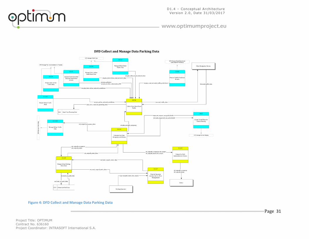
Project Title: OPTIMUM
Contract No. 636160 Project Coordinator: INTRASOFT International S.A.
Page 31
D1.4 – Conceptual Architecture
Version 2.0, Date 31/03/2017
Figure 4: DFD Collect and Manage Data Parking Data
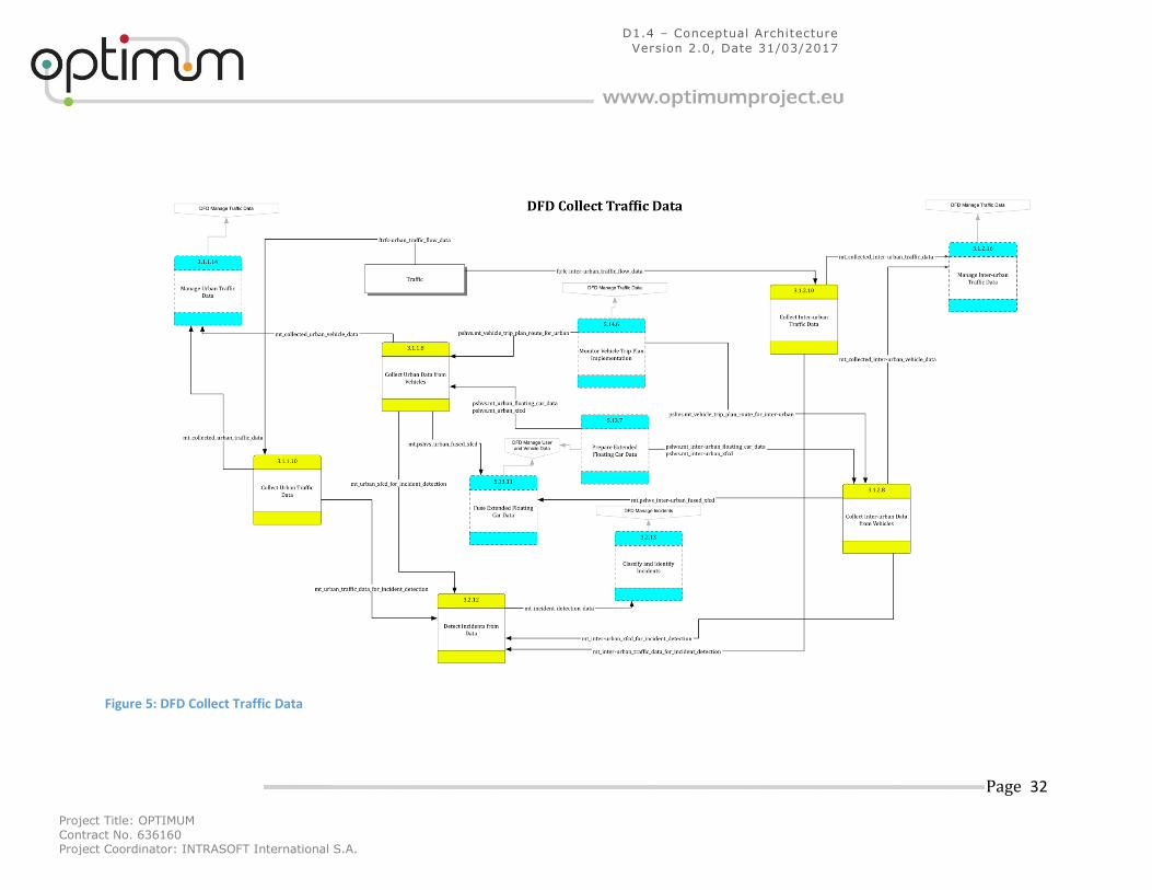
Project Title: OPTIMUM
Contract No. 636160 Project Coordinator: INTRASOFT International S.A.
Page 32
D1.4 – Conceptual Architecture
Version 2.0, Date 31/03/2017
Figure 5: DFD Collect Traffic Data
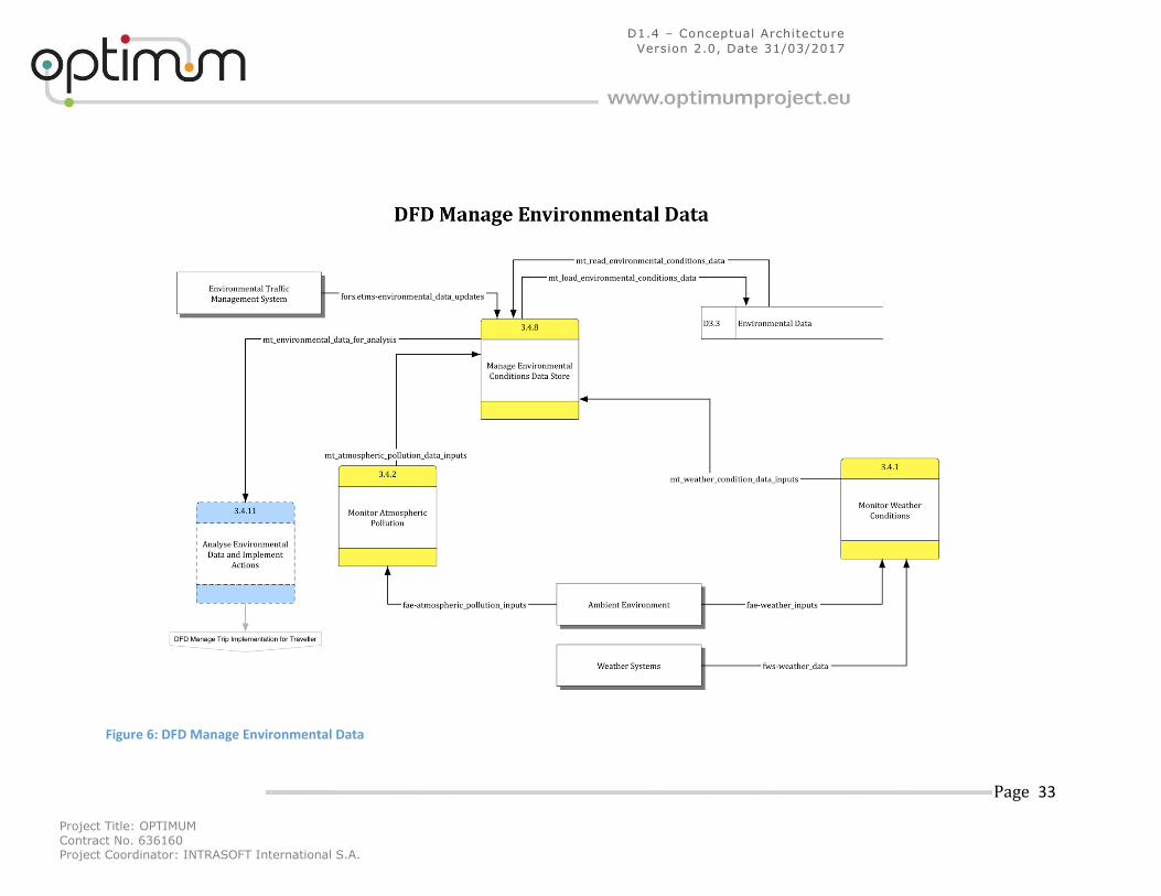
Project Title: OPTIMUM
Contract No. 636160 Project Coordinator: INTRASOFT International S.A.
Page 33
D1.4 – Conceptual Architecture
Version 2.0, Date 31/03/2017
Figure 6: DFD Manage Environmental Data
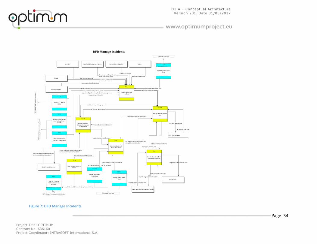
Project Title: OPTIMUM
Contract No. 636160 Project Coordinator: INTRASOFT International S.A.
Page 34
D1.4 – Conceptual Architecture
Version 2.0, Date 31/03/2017
Figure 7: DFD Manage Incidents
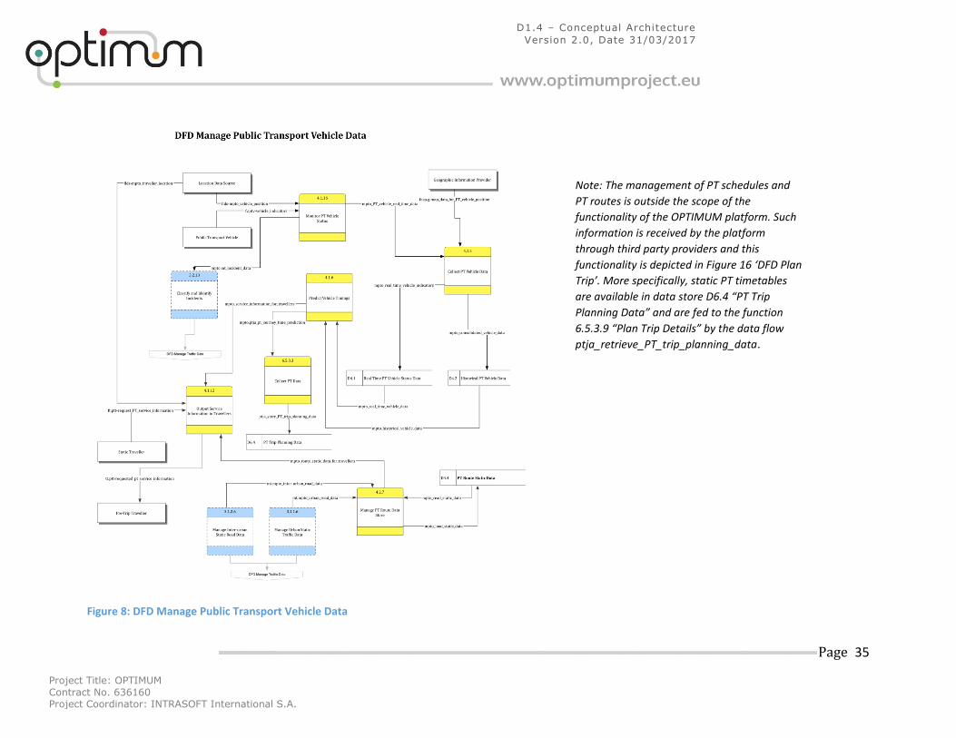
Project Title: OPTIMUM
Contract No. 636160 Project Coordinator: INTRASOFT International S.A.
Page 35
D1.4 – Conceptual Architecture
Version 2.0, Date 31/03/2017
Figure 8: DFD Manage Public Transport Vehicle Data
Note: The management of PT schedules and
PT routes is outside the scope of the
functionality of the OPTIMUM platform. Such
information is received by the platform
through third party providers and this
functionality is depicted in Figure 16 ‘DFD Plan
Trip’. More specifically, static PT timetables
are available in data store D6.4 “PT Trip
Planning Data” and are fed to the function
6.5.3.9 “Plan Trip Details” by the data flow
ptja_retrieve_PT_trip_planning_data.
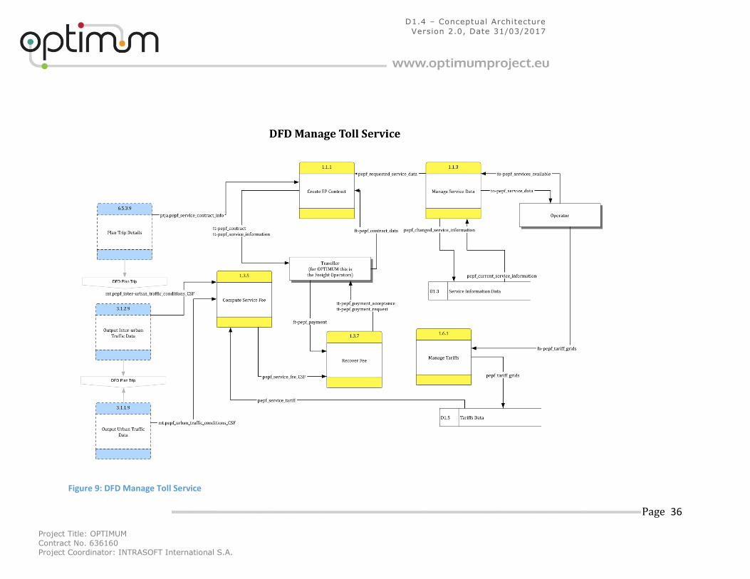
Project Title: OPTIMUM
Contract No. 636160 Project Coordinator: INTRASOFT International S.A.
Page 36
D1.4 – Conceptual Architecture
Version 2.0, Date 31/03/2017
Figure 9: DFD Manage Toll Service
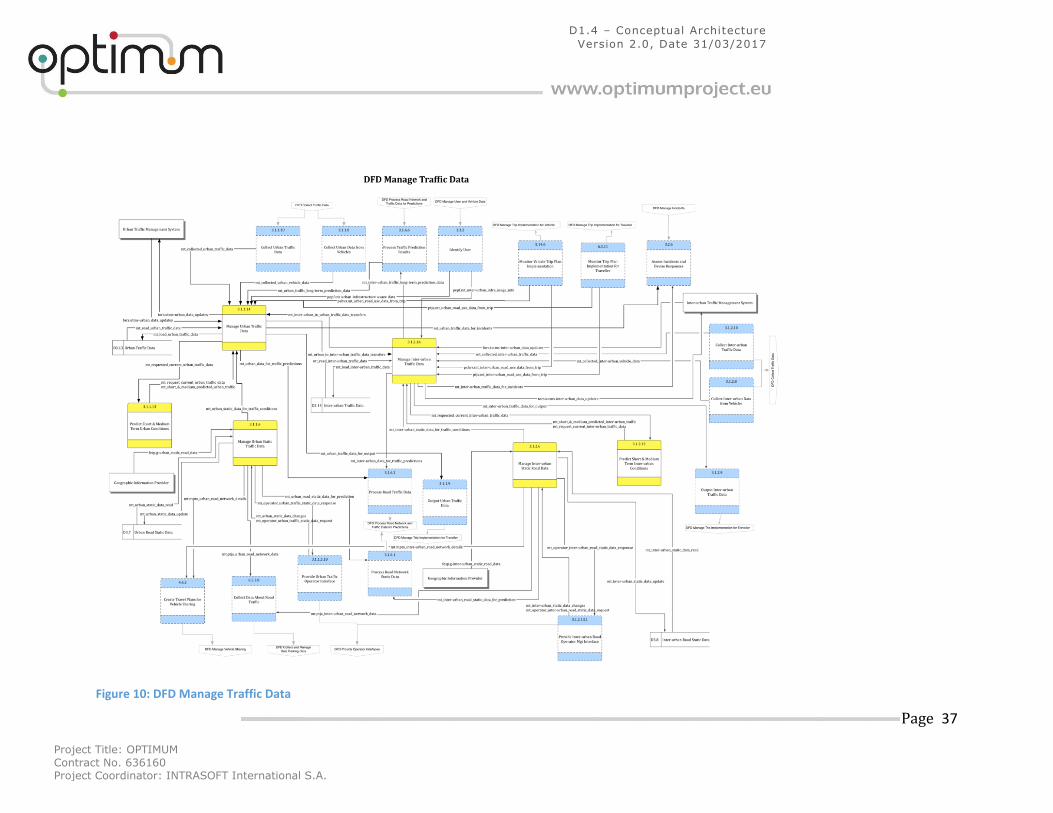
Project Title: OPTIMUM
Contract No. 636160 Project Coordinator: INTRASOFT International S.A.
Page 37
D1.4 – Conceptual Architecture
Version 2.0, Date 31/03/2017
Figure 10: DFD Manage Traffic Data
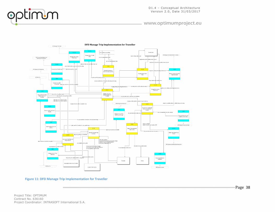
Project Title: OPTIMUM
Contract No. 636160 Project Coordinator: INTRASOFT International S.A.
Page 38
D1.4 – Conceptual Architecture
Version 2.0, Date 31/03/2017
Figure 11: DFD Manage Trip Implementation for Traveller
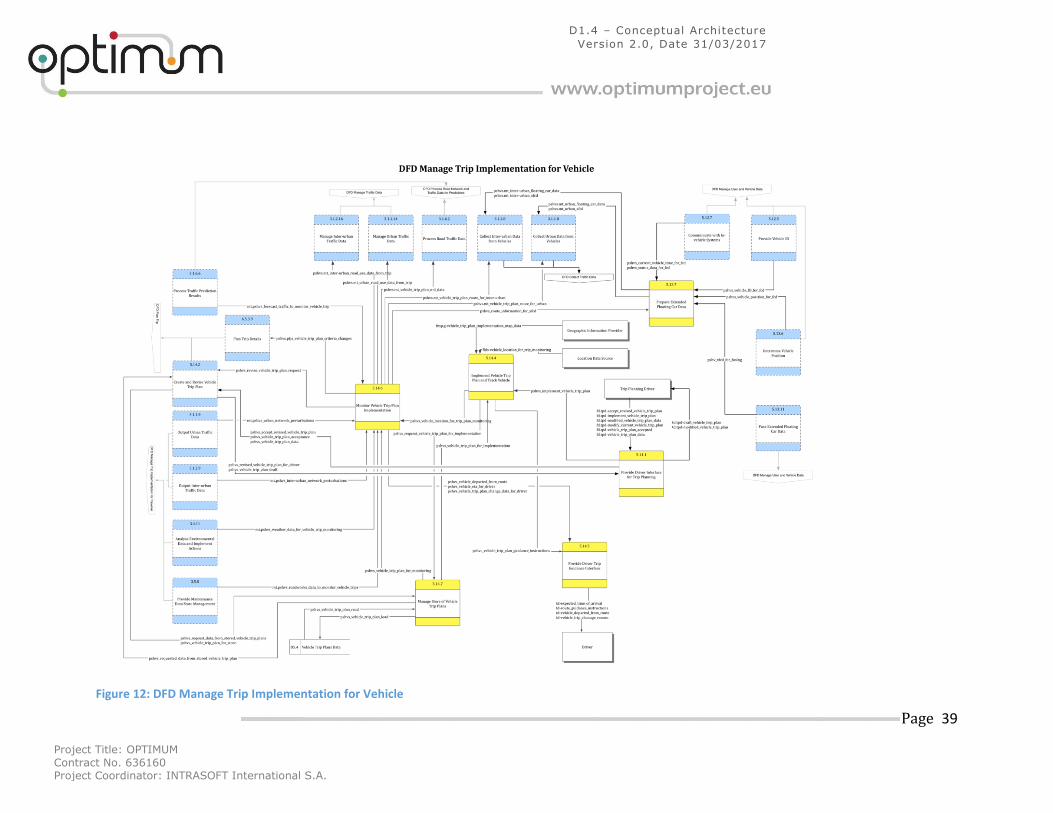
Project Title: OPTIMUM
Contract No. 636160 Project Coordinator: INTRASOFT International S.A.
Page 39
D1.4 – Conceptual Architecture
Version 2.0, Date 31/03/2017
Figure 12: DFD Manage Trip Implementation for Vehicle
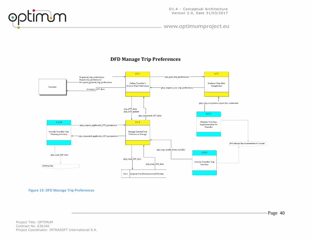
Project Title: OPTIMUM
Contract No. 636160 Project Coordinator: INTRASOFT International S.A.
Page 40
D1.4 – Conceptual Architecture
Version 2.0, Date 31/03/2017
Figure 13: DFD Manage Trip Preferences
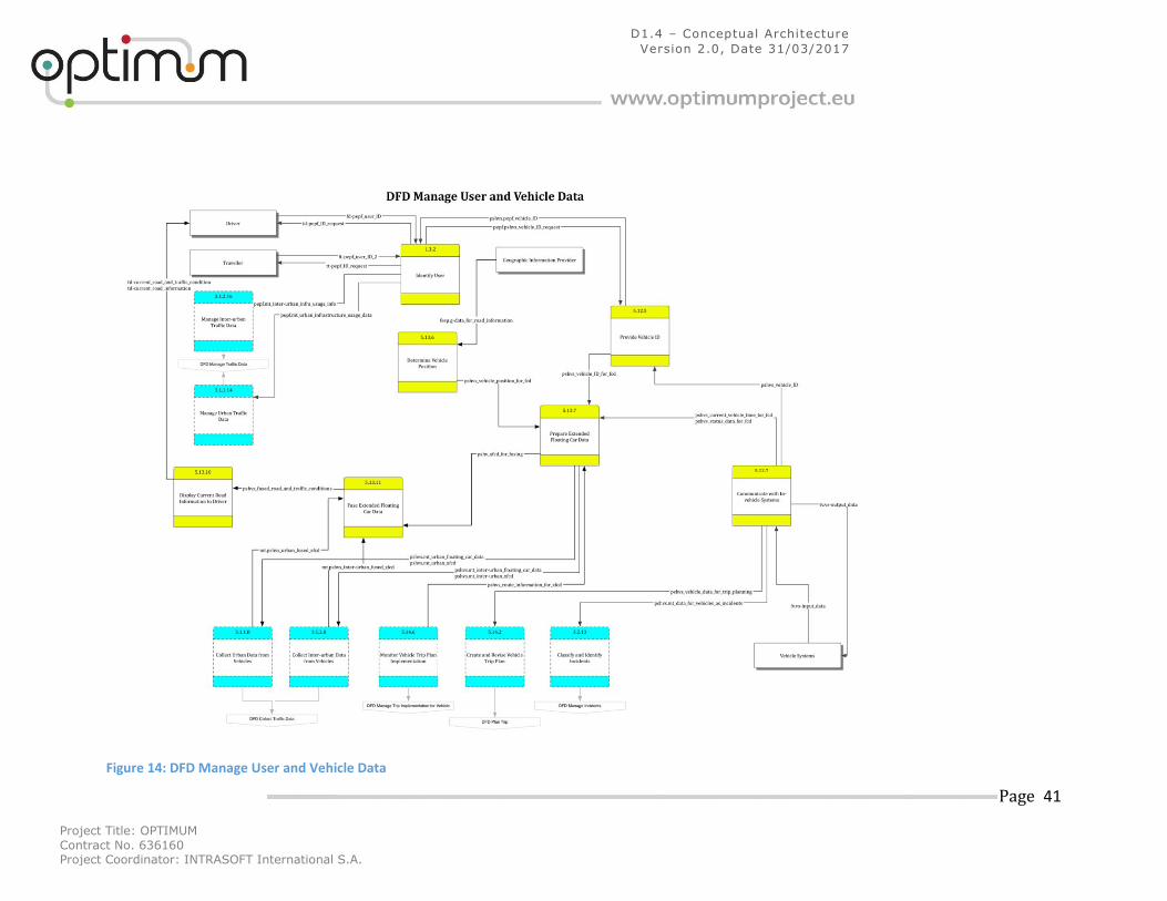
Project Title: OPTIMUM
Contract No. 636160 Project Coordinator: INTRASOFT International S.A.
Page 41
D1.4 – Conceptual Architecture
Version 2.0, Date 31/03/2017
Figure 14: DFD Manage User and Vehicle Data
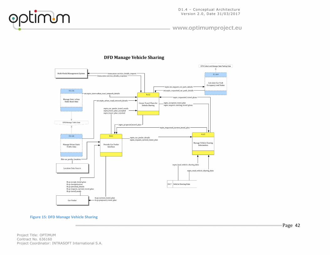
Project Title: OPTIMUM
Contract No. 636160 Project Coordinator: INTRASOFT International S.A.
Page 42
D1.4 – Conceptual Architecture
Version 2.0, Date 31/03/2017
Figure 15: DFD Manage Vehicle Sharing
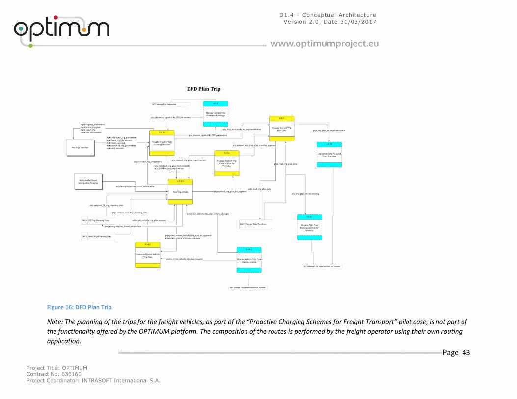
Project Title: OPTIMUM
Contract No. 636160 Project Coordinator: INTRASOFT International S.A.
Page 43
D1.4 – Conceptual Architecture
Version 2.0, Date 31/03/2017
Figure 16: DFD Plan Trip
Note: The planning of the trips for the freight vehicles, as part of the “Proactive Charging Schemes for Freight Transport” pilot case, is not part of
the functionality offered by the OPTIMUM platform. The composition of the routes is performed by the freight operator using their own routing
application.
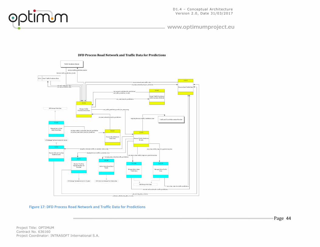
Project Title: OPTIMUM
Contract No. 636160 Project Coordinator: INTRASOFT International S.A.
Page 44
D1.4 – Conceptual Architecture
Version 2.0, Date 31/03/2017
Figure 17: DFD Process Road Network and Traffic Data for Predictions
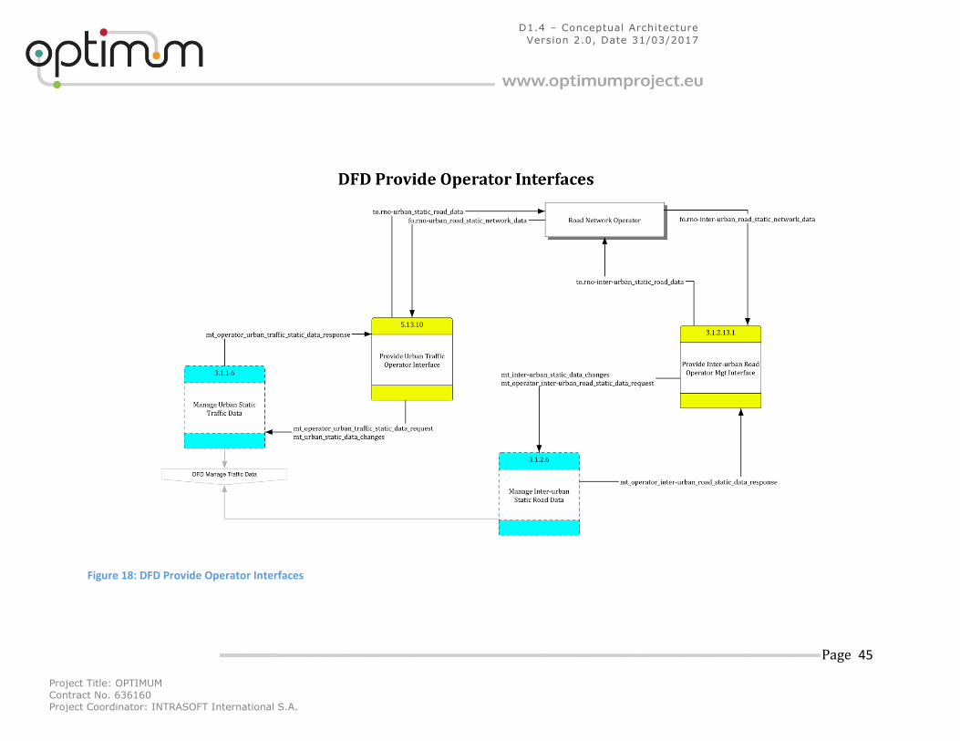
Project Title: OPTIMUM
Contract No. 636160 Project Coordinator: INTRASOFT International S.A.
Page 45
D1.4 – Conceptual Architecture
Version 2.0, Date 31/03/2017
Figure 18: DFD Provide Operator Interfaces
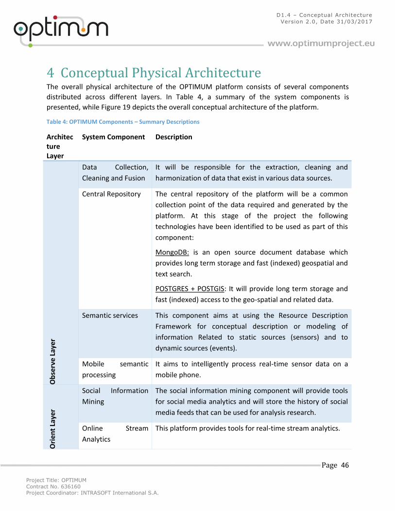
Project Title: OPTIMUM
Contract No. 636160 Project Coordinator: INTRASOFT International S.A.
Page 46
D1.4 – Conceptual Architecture
Version 2.0, Date 31/03/2017
4 Conceptual Physical Architecture The overall physical architecture of the OPTIMUM platform consists of several components
distributed across different layers. In Table 4, a summary of the system components is
presented, while Figure 19 depicts the overall conceptual architecture of the platform.
Table 4: OPTIMUM Components – Summary Descriptions
Architecture Layer
System Component Description
Ob
serv
e La
yer
Data Collection,
Cleaning and Fusion
It will be responsible for the extraction, cleaning and
harmonization of data that exist in various data sources.
Central Repository The central repository of the platform will be a common
collection point of the data required and generated by the
platform. At this stage of the project the following
technologies have been identified to be used as part of this
component:
MongoDB: is an open source document database which
provides long term storage and fast (indexed) geospatial and
text search.
POSTGRES + POSTGIS: It will provide long term storage and
fast (indexed) access to the geo-spatial and related data.
Semantic services This component aims at using the Resource Description
Framework for conceptual description or modeling of
information Related to static sources (sensors) and to
dynamic sources (events).
Mobile semantic
processing
It aims to intelligently process real-time sensor data on a
mobile phone.
Ori
ent
Laye
r
Social Information
Mining
The social information mining component will provide tools
for social media analytics and will store the history of social
media feeds that can be used for analysis research.
Online Stream
Analytics
This platform provides tools for real-time stream analytics.
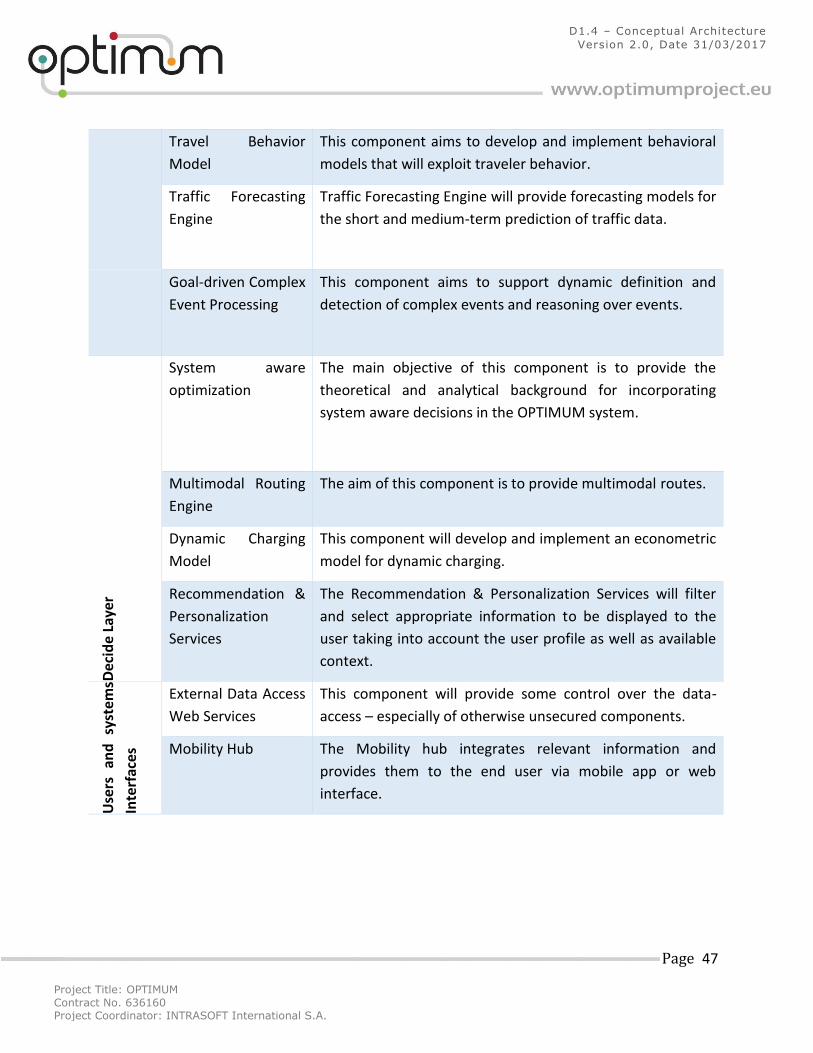
Project Title: OPTIMUM
Contract No. 636160 Project Coordinator: INTRASOFT International S.A.
Page 47
D1.4 – Conceptual Architecture
Version 2.0, Date 31/03/2017
Travel Behavior
Model
This component aims to develop and implement behavioral
models that will exploit traveler behavior.
Traffic Forecasting
Engine
Traffic Forecasting Engine will provide forecasting models for
the short and medium-term prediction of traffic data.
Goal-driven Complex
Event Processing
This component aims to support dynamic definition and
detection of complex events and reasoning over events.
Dec
ide
Laye
r
System aware
optimization
The main objective of this component is to provide the
theoretical and analytical background for incorporating
system aware decisions in the OPTIMUM system.
Multimodal Routing
Engine
The aim of this component is to provide multimodal routes.
Dynamic Charging
Model
This component will develop and implement an econometric
model for dynamic charging.
Recommendation &
Personalization
Services
The Recommendation & Personalization Services will filter
and select appropriate information to be displayed to the
user taking into account the user profile as well as available
context.
Use
rs
and
sy
stem
s
Inte
rfac
es
External Data Access
Web Services
This component will provide some control over the data-
access – especially of otherwise unsecured components.
Mobility Hub The Mobility hub integrates relevant information and
provides them to the end user via mobile app or web
interface.
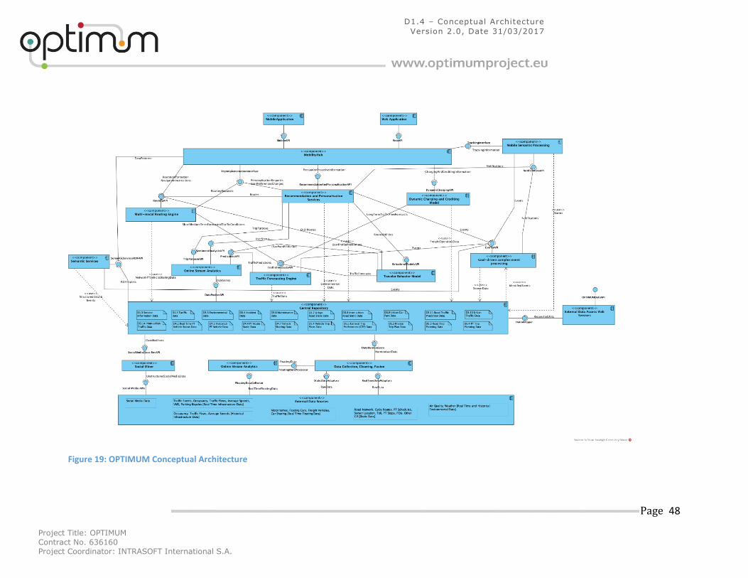
Project Title: OPTIMUM
Contract No. 636160 Project Coordinator: INTRASOFT International S.A.
Page 48
D1.4 – Conceptual Architecture
Version 2.0, Date 31/03/2017
Figure 19: OPTIMUM Conceptual Architecture
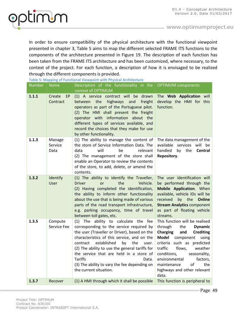
Project Title: OPTIMUM
Contract No. 636160 Project Coordinator: INTRASOFT International S.A.
Page 49
D1.4 – Conceptual Architecture
Version 2.0, Date 31/03/2017
In order to ensure compatibility of the physical architecture with the functional viewpoint
presented in chapter 3, Table 5 aims to map the different selected FRAME ITS functions to the
components of the architecture presented in Figure 19. The description of each function has
been taken from the FRAME ITS architecture and has been customized, where necessary, to the
context of the project. For each function, a description of how it is envisaged to be realized
through the different components is provided. Table 5: Mapping of Functional Viewpoint with Physical Architecture
Number Name Description of the functionality in the context of OPTIMUM
OPTIMUM components
1.1.1 Create EP Contract
(1) A service contract will be drawn between the highways and freight operators as part of the Portuguese pilot. (2) The HMI shall present the freight operator with information about the different types of services available, and record the choices that they make for use by other functionality.
The Web Application will develop the HMI for this function.
1.1.3 Manage Service Data
(1) The ability to manage the content of the store of Service Information Data. The data will be relevant (2) The management of the store shall enable an Operator to review the contents of the store, to add, delete, or amend the contents.
The data management of the available services will be handled by the Central Repository.
1.3.2 Identify User
(1) The ability to identify the Traveller, Driver or the Vehicle. (2) Having completed the identification, the ability to inform other functionality about the use that is being made of various parts of the road transport infrastructure, e.g. parking occupancy, time of travel between toll gates, etc.
The user identification will be performed through the Mobile Application. When available, vehicle IDs will be received by the Online Stream Analytics component as part of floating vehicle streams.
1.3.5 Compute Service Fee
(1) The ability to calculate the fee corresponding to the service required by the user (Traveller or Driver), based on the characteristics of this service, and on the contract established by the user. (2) The ability to use the general tariffs for the service that are held in a store of Tariffs Data. (3) The ability to vary the fee depending on the current situation.
This function will be realised through the Dynamic Charging and Crediting Model component using criteria such as predicted traffic flows, weather conditions, seasonality, environmental factors, maintenance of the highways and other relevant data.
1.3.7 Recover (1) A HMI through which it shall be possible This function is peripheral to
Project Title: OPTIMUM
Contract No. 636160 Project Coordinator: INTRASOFT International S.A.
Page 50
D1.4 – Conceptual Architecture
Version 2.0, Date 31/03/2017
Fee to ask the Traveller or Driver for payment for the selected service.
the scope of OPTIMUM. The Web Application will display the published calculated toll fees but payments will be managed outside the system.
1.6.1 Manage Tariffs
(1) The ability to manage the store of "tariffs" Data. (3) The ability to define within the store, the structure in which the "tariffs" data will be stored, with different structures being possible for PT fares and charges for road use.
The toll tariffs generated by the Dynamic Charging and Crediting Model will be stored and be managed by the Central Repository using data structures that will be developed as part of the project.
3.1.1.5.10
Provide Urban Traffic Operator Interface
(4) The ability of the Road Network Operator to request and be provided with the current contents of the store of Urban Road Static Data through the Manage Urban Static Traffic Data Function.
Different data layouts of the status of the transport networks will be available to the pilot users through the Web Application.
3.1.1.6 Manage Urban Static Traffic Data
(1) The management of the store of Urban Road Static Data for use by the urban traffic management functionality. (2) The entry into the store of new and/or updated road network static data received from the Geographic Information Provider and/or the Road Network Operator via the operator interface functionality. (4) The provision of new and/or updated road network static data provided by the Road Network Operator to the functionality that will send the data to the Geographic Information Provider so that it can be used when digital map data is provided in the future.
Harmonised static urban data will be stored in the Central Repository after cleaning and fusion from the Data Collection, Cleaning, Fusion component.
3.1.1.8 Collect Urban Data from Vehicles
(1) The collection of Floating Car Data (FCD) and Extended Floating Car Data (XFCD) from suitable equipped Vehicles that are using the urban road network. (2) The Function shall expect the data to be the raw input data provided by functionality in the Vehicle and to contain location information, time plus Vehicle identity and status data. (3) The processing of the collected data to provide actual traffic flow data, e.g. flow,
The Online Stream Analytics component will collect floating vehicle data from Adria’s motorhomes and other available fleets. Using predictive analytics techniques, the data will be fused, processed and stored (through the Data Collection, Cleaning, Fusion component when necessary)
Project Title: OPTIMUM
Contract No. 636160 Project Coordinator: INTRASOFT International S.A.
Page 51
D1.4 – Conceptual Architecture
Version 2.0, Date 31/03/2017
speed, for the urban road network, Vehicle status data, e.g. broken down, other road related data, e.g. rain, fog, slippery road, ice and to detect incidents. (4) The checking of the collected data for coherence and consistency both for individual Vehicles and for the traffic as a whole in each segment of the urban road network. (5) The exchange of data with the Monitor Urban FCD/XFCD Source Vehicles Function to confirm that the collected data actually comes from the Vehicles whose identities are included in the data, and to discard all data except traffic flow data from Vehicles being driven safely. (6) The provision of the processed and collected data to the Detect Incidents from Data and Urban Traffic Data Management Functions. (7) The ability to make all processed data anonymous so that the movement through the urban road network of specific Vehicles cannot be identified.
in the Central Repository. If necessary, the data will be available through dedicated interfaces to other components of the platform to provide functionality related to traffic prediction, routing, incident detection and others.
3.1.1.9 Output Urban Traffic Data
(1) The output of data about current traffic conditions in the urban road network received from the Urban Traffic Data Management Function. (2) Both sets of outputs shall be sent as soon as new data is received to functionality in the Provide Traveller Journey Assistance Functional Areas, plus the Broadcast and Traffic and Travel Information Provider. (3) Both sets of outputs shall also be sent as soon as new data is received to the Broadcaster and Traffic and Travel Information Provider, or to the Broadcaster when it provides a request.
Processed urban traffic data generated by the platform will be available to third-party providers through the External Data Access Web Services component.
3.1.1.10 Collect Urban Traffic Data
(1) The collection of traffic flow data from sensors that are located within the urban road network managed by the System. (2) The sensors shall be capable of detecting the presence of all types of road Vehicle, from Bicycles to Heavy Goods
Through the development of various data adaptors, the Data Collection, Cleaning, Fusion component will collect, clean and fuse traffic data. The internal data
Project Title: OPTIMUM
Contract No. 636160 Project Coordinator: INTRASOFT International S.A.
Page 52
D1.4 – Conceptual Architecture
Version 2.0, Date 31/03/2017
Vehicles. (3) The processing of the raw input data provided by the sensors into actual traffic flow data, i.e. vehicle flow rates, vehicle speeds, etc. (4) The supply of the processed raw input data to other functionality in the Manage Traffic Functional Area for collation and use.
processing pipeline of the component will generate harmonised traffic data that will be stored in the Central Repository.
3.1.1.13 Predict Short & Medium Term Urban Conditions
(1) The ability to create short and medium term predictions of urban traffic data. (2) The ability to create the predictions of short and medium term urban traffic data using algorithms that may be different in content and scope. (3) The ability to request and use current urban traffic data as the starting point for the predictions of short and medium term urban traffic data. (4) The ability to repeat the creation of the predicted short and medium term urban traffic data at (frequent?) periodic intervals.
Using a combination of parametric, non-parametric and hybrid algorithms the Traffic Forecasting Engine will generate predictions of urban traffic data.
3.1.1.14 Manage Urban Traffic Data
(1) The ability to manage the store of Inter-urban Traffic Data. (2) The ability to collect data about traffic conditions (i.e. traffic flows, road segment use, journey times, etc.) in the urban road network and car park data from other functionality in the Manage Traffic Functional Area. (4) The ability to collate and fuse all data that is collected and received, using the inter-urban road network static data as a mechanism for achieving this where necessary. (6) The ability to load the collated and fused data into the store of Urban Traffic Data in a coherent way that makes it easy to retrieve it for particular road segments, or larger parts of the urban road network. (7) The ability to provide the collated and fused data from the store of Urban Traffic Data to other functionality in the Manage Traffic area, either for its own use, or for
This functionality will be realised by the sub-components within the Data Collection, Cleaning, Fusion component and the Central Repository.
Project Title: OPTIMUM
Contract No. 636160 Project Coordinator: INTRASOFT International S.A.
Page 53
D1.4 – Conceptual Architecture
Version 2.0, Date 31/03/2017
sending to functionality in other Functional Areas and to entities outside the System. (8) The ability to provide current urban traffic data for use in creating short and medium term predictions for that data and when received to load that data into the store of Urban Traffic Data.
3.1.2.6 Manage Inter-urban Static Road Data
(1) The ability to take responsibility for managing the store of Inter-urban Road Static Data that is used by inter-urban traffic management functionality. (2) Every time a new set of data is received from the Geographic Information Provider, the ability to make it available to the inter-urban traffic management functionality and to load it into the store.
Harmonised inter-urban static road data will be stored in the Central Repository after cleaning and fusion from the Data Collection, Cleaning, Fusion component.
3.1.2.8 Collect Inter-urban Data from Vehicles
(1) The ability to collect Floating Car Data (FCD) and Extended Floating Car Data (XFCD) about Vehicles that are using the inter-urban road network. (2) The ability to collect the data as raw input from functionality within the Vehicles. (3) The raw input data shall be expected to contain location information, time and Vehicle status data. (4) The ability to process the collected data to provide actual traffic flow data, e.g. flow, speed, for the inter-urban road network, Vehicle status data, e.g. broken down, other road related data, e.g. rain, fog, slippery road, ice and to detect incidents. (5) As part of this processing, the ability to check the coherence and consistency of the data both for individual Vehicles and for the traffic as a whole in each segment of the inter-urban road network. (8) The ability to pass the processed data to the incident management functionality for collation and to other traffic management functionality for use in managing the traffic using the inter-urban road network. (9) The ability to make all processed data
The Online Stream Analytics component will collect floating vehicle data from Adria’s motorhomes and other available fleets. Using predictive analytics techniques, the data will be fused, processed and stored (through the Data Collection, Cleaning, Fusion component when necessary) in the Central Repository. If necessary, the data will be available through dedicated interfaces to other components of the platform to provide functionality related to traffic prediction, routing, incident detection and others.
Project Title: OPTIMUM
Contract No. 636160 Project Coordinator: INTRASOFT International S.A.
Page 54
D1.4 – Conceptual Architecture
Version 2.0, Date 31/03/2017
anonymous so that the movement through the urban road network of specific Vehicles cannot be identified.
3.1.2.9 Output Inter-urban Traffic Data
(1) The ability to periodically receive data about current traffic conditions in the inter-urban road network from the functionality that manages the store of Inter-urban Traffic Data. (2) The ability to immediately output the data which has been received to other parts of the System or to entities that are outside of the System. (3) When a request is received from the Broadcaster entity, the ability to output the latest set of data that is available about inter-urban traffic conditions.
Processed inter-urban traffic data generated by the platform will be available to third-party providers through the External Data Access Web Services component.
3.1.2.10 Collect Inter-urban Traffic Data
(1) The ability to collect traffic data from the inter-urban road network. (2) The ability for sensors within this Function to provide the data as raw input
Through the development of various data adaptors, the Data Collection, Cleaning, Fusion component will
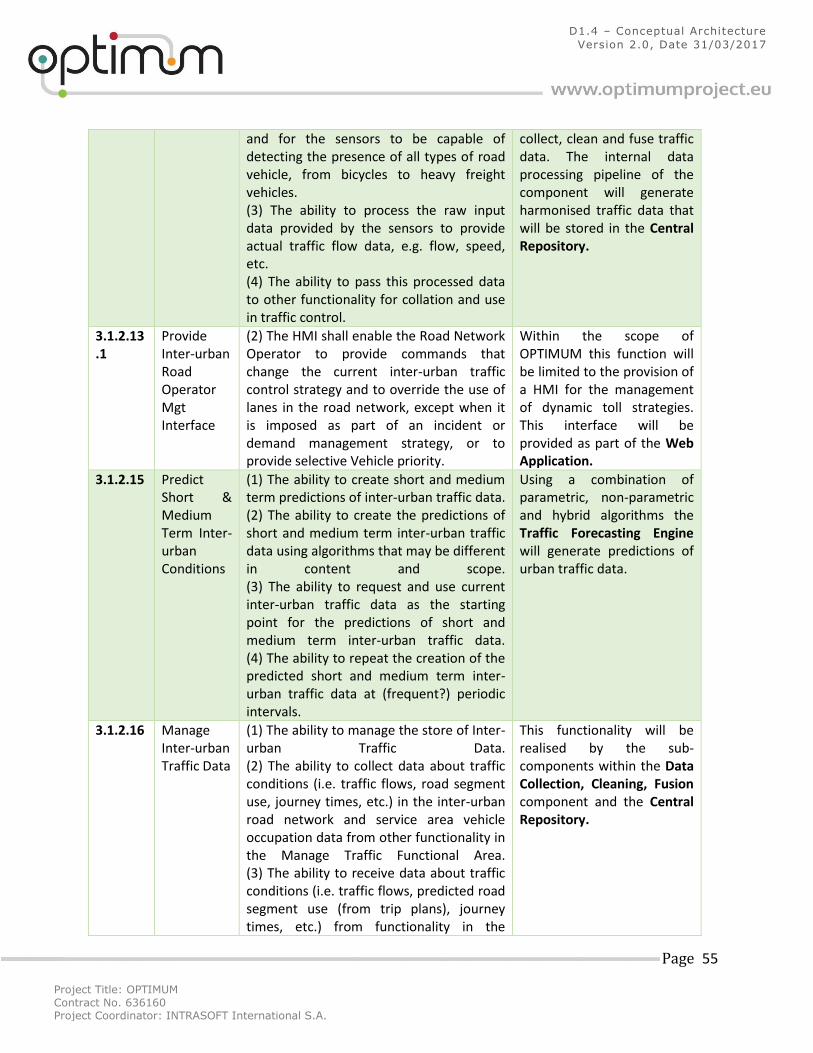
Project Title: OPTIMUM
Contract No. 636160 Project Coordinator: INTRASOFT International S.A.
Page 55
D1.4 – Conceptual Architecture
Version 2.0, Date 31/03/2017
and for the sensors to be capable of detecting the presence of all types of road vehicle, from bicycles to heavy freight vehicles. (3) The ability to process the raw input data provided by the sensors to provide actual traffic flow data, e.g. flow, speed, etc. (4) The ability to pass this processed data to other functionality for collation and use in traffic control.
collect, clean and fuse traffic data. The internal data processing pipeline of the component will generate harmonised traffic data that will be stored in the Central Repository.
3.1.2.13.1
Provide Inter-urban Road Operator Mgt Interface
(2) The HMI shall enable the Road Network Operator to provide commands that change the current inter-urban traffic control strategy and to override the use of lanes in the road network, except when it is imposed as part of an incident or demand management strategy, or to provide selective Vehicle priority.
Within the scope of OPTIMUM this function will be limited to the provision of a HMI for the management of dynamic toll strategies. This interface will be provided as part of the Web Application.
3.1.2.15 Predict Short & Medium Term Inter-urban Conditions
(1) The ability to create short and medium term predictions of inter-urban traffic data. (2) The ability to create the predictions of short and medium term inter-urban traffic data using algorithms that may be different in content and scope. (3) The ability to request and use current inter-urban traffic data as the starting point for the predictions of short and medium term inter-urban traffic data. (4) The ability to repeat the creation of the predicted short and medium term inter-urban traffic data at (frequent?) periodic intervals.
Using a combination of parametric, non-parametric and hybrid algorithms the Traffic Forecasting Engine will generate predictions of urban traffic data.
3.1.2.16 Manage Inter-urban Traffic Data
(1) The ability to manage the store of Inter-urban Traffic Data. (2) The ability to collect data about traffic conditions (i.e. traffic flows, road segment use, journey times, etc.) in the inter-urban road network and service area vehicle occupation data from other functionality in the Manage Traffic Functional Area. (3) The ability to receive data about traffic conditions (i.e. traffic flows, predicted road segment use (from trip plans), journey times, etc.) from functionality in the
This functionality will be realised by the sub-components within the Data Collection, Cleaning, Fusion component and the Central Repository.
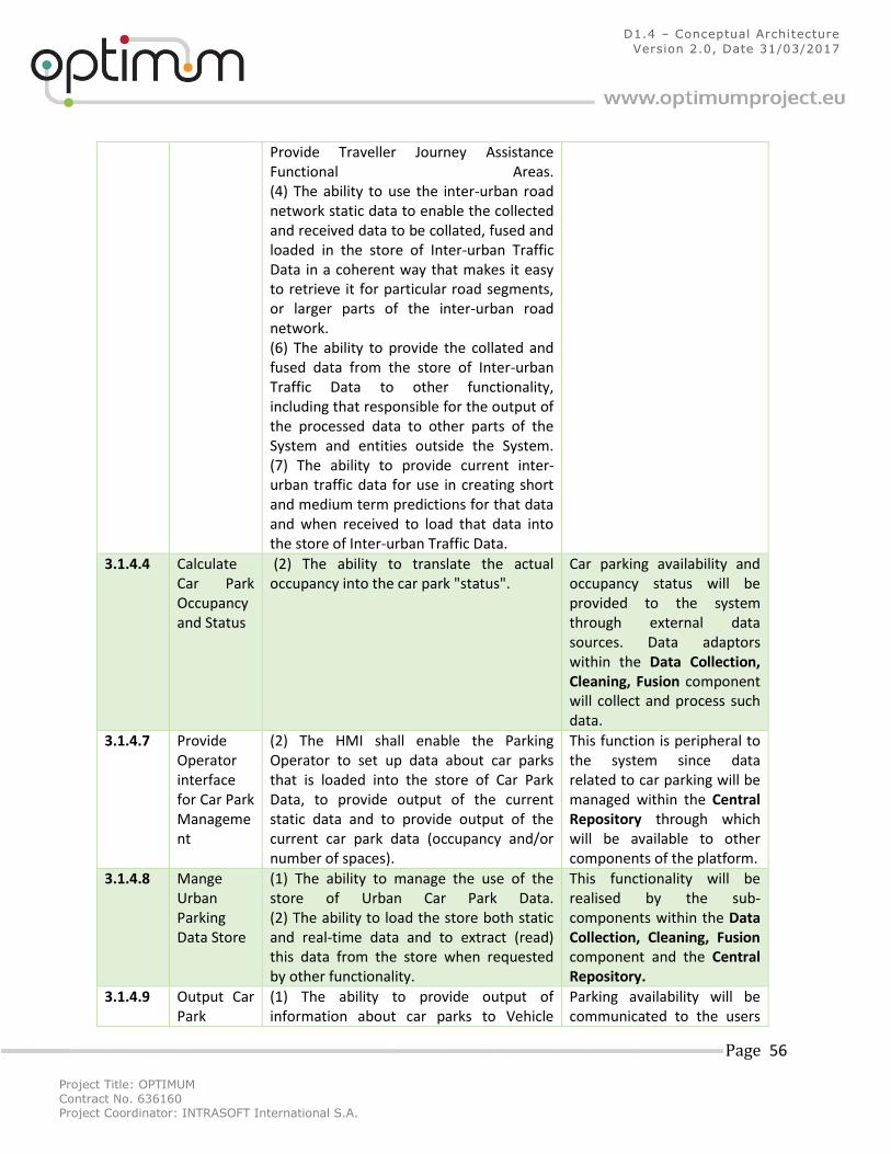
Project Title: OPTIMUM
Contract No. 636160 Project Coordinator: INTRASOFT International S.A.
Page 56
D1.4 – Conceptual Architecture
Version 2.0, Date 31/03/2017
Provide Traveller Journey Assistance Functional Areas. (4) The ability to use the inter-urban road network static data to enable the collected and received data to be collated, fused and loaded in the store of Inter-urban Traffic Data in a coherent way that makes it easy to retrieve it for particular road segments, or larger parts of the inter-urban road network. (6) The ability to provide the collated and fused data from the store of Inter-urban Traffic Data to other functionality, including that responsible for the output of the processed data to other parts of the System and entities outside the System. (7) The ability to provide current inter-urban traffic data for use in creating short and medium term predictions for that data and when received to load that data into the store of Inter-urban Traffic Data.
3.1.4.4 Calculate Car Park Occupancy and Status
(2) The ability to translate the actual occupancy into the car park "status".
Car parking availability and occupancy status will be provided to the system through external data sources. Data adaptors within the Data Collection, Cleaning, Fusion component will collect and process such data.
3.1.4.7 Provide Operator interface for Car Park Management
(2) The HMI shall enable the Parking Operator to set up data about car parks that is loaded into the store of Car Park Data, to provide output of the current static data and to provide output of the current car park data (occupancy and/or number of spaces).
This function is peripheral to the system since data related to car parking will be managed within the Central Repository through which will be available to other components of the platform.
3.1.4.8 Mange Urban Parking Data Store
(1) The ability to manage the use of the store of Urban Car Park Data. (2) The ability to load the store both static and real-time data and to extract (read) this data from the store when requested by other functionality.
This functionality will be realised by the sub-components within the Data Collection, Cleaning, Fusion component and the Central Repository.
3.1.4.9 Output Car Park
(1) The ability to provide output of information about car parks to Vehicle
Parking availability will be communicated to the users
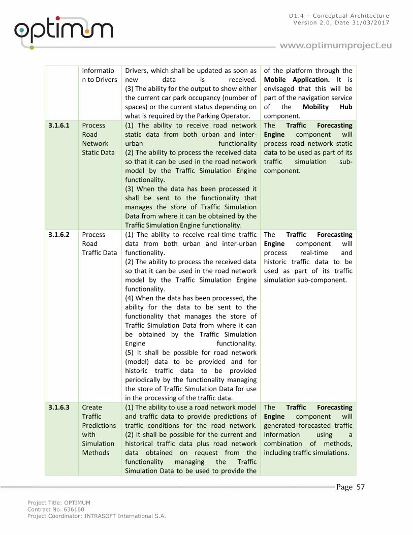
Project Title: OPTIMUM
Contract No. 636160 Project Coordinator: INTRASOFT International S.A.
Page 57
D1.4 – Conceptual Architecture
Version 2.0, Date 31/03/2017
Information to Drivers
Drivers, which shall be updated as soon as new data is received. (3) The ability for the output to show either the current car park occupancy (number of spaces) or the current status depending on what is required by the Parking Operator.
of the platform through the Mobile Application. It is envisaged that this will be part of the navigation service of the Mobility Hub component.
3.1.6.1 Process Road Network Static Data
(1) The ability to receive road network static data from both urban and inter-urban functionality (2) The ability to process the received data so that it can be used in the road network model by the Traffic Simulation Engine functionality. (3) When the data has been processed it shall be sent to the functionality that manages the store of Traffic Simulation Data from where it can be obtained by the Traffic Simulation Engine functionality.
The Traffic Forecasting Engine component will process road network static data to be used as part of its traffic simulation sub-component.
3.1.6.2 Process Road Traffic Data
(1) The ability to receive real-time traffic data from both urban and inter-urban functionality. (2) The ability to process the received data so that it can be used in the road network model by the Traffic Simulation Engine functionality. (4) When the data has been processed, the ability for the data to be sent to the functionality that manages the store of Traffic Simulation Data from where it can be obtained by the Traffic Simulation Engine functionality. (5) It shall be possible for road network (model) data to be provided and for historic traffic data to be provided periodically by the functionality managing the store of Traffic Simulation Data for use in the processing of the traffic data.
The Traffic Forecasting Engine component will process real-time and historic traffic data to be used as part of its traffic simulation sub-component.
3.1.6.3 Create Traffic Predictions with Simulation Methods
(1) The ability to use a road network model and traffic data to provide predictions of traffic conditions for the road network. (2) It shall be possible for the current and historical traffic data plus road network data obtained on request from the functionality managing the Traffic Simulation Data to be used to provide the
The Traffic Forecasting Engine component will generated forecasted traffic information using a combination of methods, including traffic simulations.
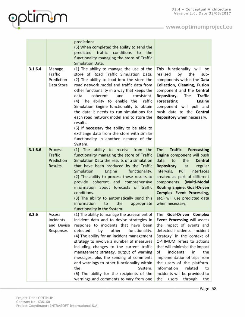
Project Title: OPTIMUM
Contract No. 636160 Project Coordinator: INTRASOFT International S.A.
Page 58
D1.4 – Conceptual Architecture
Version 2.0, Date 31/03/2017
predictions. (5) When completed the ability to send the predicted traffic conditions to the functionality managing the store of Traffic Simulation Data.
3.1.6.4 Manage Traffic Prediction Data Store
(1) The ability to manage the use of the store of Road Traffic Simulation Data. (2) The ability to load into the store the road network model and traffic data from other functionality in a way that keeps the data coherent and consistent. (4) The ability to enable the Traffic Simulation Engine functionality to obtain the data it needs to run simulations for each road network model and to store the results. (6) If necessary the ability to be able to exchange data from the store with similar functionality in another instance of the System.
This functionality will be realised by the sub-components within the Data Collection, Cleaning, Fusion component and the Central Repository. The Traffic Forecasting Engine component will pull and push data to the Central Repository when necessary.
3.1.6.6 Process Traffic Prediction Results
(1) The ability to receive from the functionality managing the store of Traffic Simulation Data the results of a simulation that have been produced by the Traffic Simulation Engine functionality. (2) The ability to process these results to provide coherent and comprehensive information about forecasts of traffic conditions. (3) The ability to automatically send this information to the appropriate functionality in the System.
The Traffic Forecasting Engine component will push data to the Central Repository at regular intervals. Pull interfaces created as part of different components (Multi-Modal Routing Engine, Goal-Driven Complex Event Processing, etc.) will use predicted data when necessary.
3.2.6 Assess Incidents and Devise Responses
(1) The ability to manage the assessment of incident data and to devise strategies in response to incidents that have been detected by other functionality. (4) The ability for an incident management strategy to involve a number of measures including changes to the current traffic management strategy, output of warning messages, plus the sending of comments and warnings to other functionality within the System. (6) The ability for the recipients of the warnings and comments to vary from one
The Goal-Driven Complex Event Processing will assess the impact of events and detected incidents. ‘Incident Strategy’ in the context of OPTIMUM refers to actions that will minimise the impact of incidents in the implementation of trips from the users of the platform. Information related to incidents will be provided to the users through the
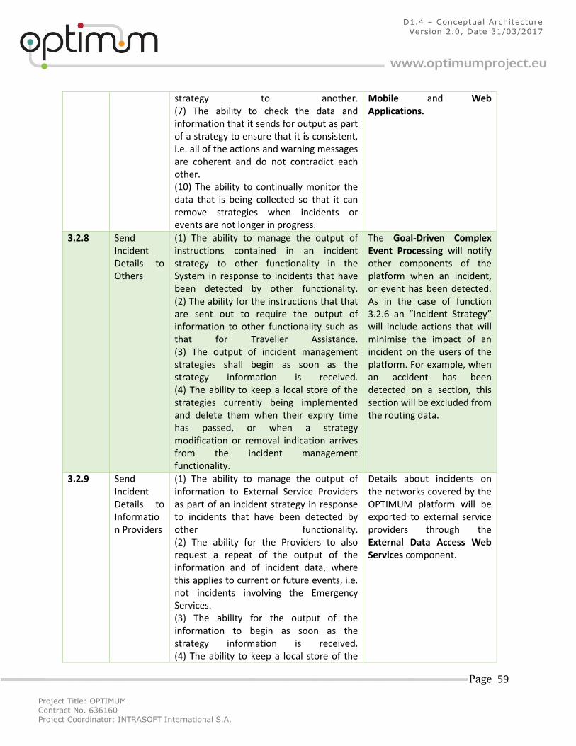
Project Title: OPTIMUM
Contract No. 636160 Project Coordinator: INTRASOFT International S.A.
Page 59
D1.4 – Conceptual Architecture
Version 2.0, Date 31/03/2017
strategy to another. (7) The ability to check the data and information that it sends for output as part of a strategy to ensure that it is consistent, i.e. all of the actions and warning messages are coherent and do not contradict each other. (10) The ability to continually monitor the data that is being collected so that it can remove strategies when incidents or events are not longer in progress.
Mobile and Web Applications.
3.2.8 Send Incident Details to Others
(1) The ability to manage the output of instructions contained in an incident strategy to other functionality in the System in response to incidents that have been detected by other functionality. (2) The ability for the instructions that that are sent out to require the output of information to other functionality such as that for Traveller Assistance. (3) The output of incident management strategies shall begin as soon as the strategy information is received. (4) The ability to keep a local store of the strategies currently being implemented and delete them when their expiry time has passed, or when a strategy modification or removal indication arrives from the incident management functionality.
The Goal-Driven Complex Event Processing will notify other components of the platform when an incident, or event has been detected. As in the case of function 3.2.6 an “Incident Strategy” will include actions that will minimise the impact of an incident on the users of the platform. For example, when an accident has been detected on a section, this section will be excluded from the routing data.
3.2.9 Send Incident Details to Information Providers
(1) The ability to manage the output of information to External Service Providers as part of an incident strategy in response to incidents that have been detected by other functionality. (2) The ability for the Providers to also request a repeat of the output of the information and of incident data, where this applies to current or future events, i.e. not incidents involving the Emergency Services. (3) The ability for the output of the information to begin as soon as the strategy information is received. (4) The ability to keep a local store of the
Details about incidents on the networks covered by the OPTIMUM platform will be exported to external service providers through the External Data Access Web Services component.
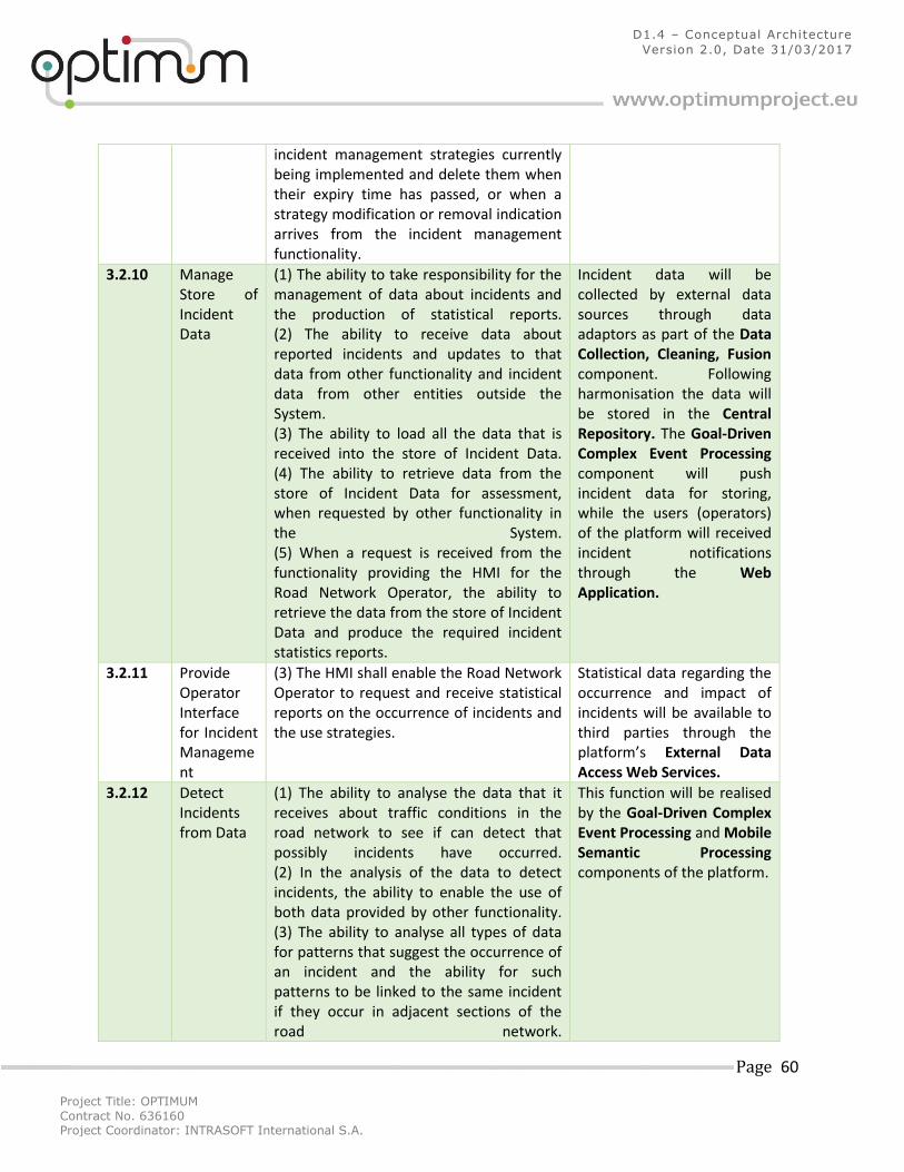
Project Title: OPTIMUM
Contract No. 636160 Project Coordinator: INTRASOFT International S.A.
Page 60
D1.4 – Conceptual Architecture
Version 2.0, Date 31/03/2017
incident management strategies currently being implemented and delete them when their expiry time has passed, or when a strategy modification or removal indication arrives from the incident management functionality.
3.2.10 Manage Store of Incident Data
(1) The ability to take responsibility for the management of data about incidents and the production of statistical reports. (2) The ability to receive data about reported incidents and updates to that data from other functionality and incident data from other entities outside the System. (3) The ability to load all the data that is received into the store of Incident Data. (4) The ability to retrieve data from the store of Incident Data for assessment, when requested by other functionality in the System. (5) When a request is received from the functionality providing the HMI for the Road Network Operator, the ability to retrieve the data from the store of Incident Data and produce the required incident statistics reports.
Incident data will be collected by external data sources through data adaptors as part of the Data Collection, Cleaning, Fusion component. Following harmonisation the data will be stored in the Central Repository. The Goal-Driven Complex Event Processing component will push incident data for storing, while the users (operators) of the platform will received incident notifications through the Web Application.
3.2.11 Provide Operator Interface for Incident Management
(3) The HMI shall enable the Road Network Operator to request and receive statistical reports on the occurrence of incidents and the use strategies.
Statistical data regarding the occurrence and impact of incidents will be available to third parties through the platform’s External Data Access Web Services.
3.2.12 Detect Incidents from Data
(1) The ability to analyse the data that it receives about traffic conditions in the road network to see if can detect that possibly incidents have occurred. (2) In the analysis of the data to detect incidents, the ability to enable the use of both data provided by other functionality. (3) The ability to analyse all types of data for patterns that suggest the occurrence of an incident and the ability for such patterns to be linked to the same incident if they occur in adjacent sections of the road network.
This function will be realised by the Goal-Driven Complex Event Processing and Mobile Semantic Processing components of the platform.
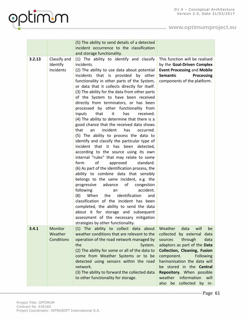
Project Title: OPTIMUM
Contract No. 636160 Project Coordinator: INTRASOFT International S.A.
Page 61
D1.4 – Conceptual Architecture
Version 2.0, Date 31/03/2017
(5) The ability to send details of a detected incident occurrence to the classification and storage functionality.
3.2.13 Classify and Identify Incidents
(1) The ability to identify and classify incidents. (2) The ability to use data about potential incidents that is provided by other functionality in other parts of the System, or data that it collects directly for itself. (3) The ability for the data from other parts of the System to have been received directly from terminators, or has been processed by other functionality from inputs that it has received. (4) The ability to determine that there is a good chance that the received data shows that an incident has occurred. (5) The ability to process the data to identify and classify the particular type of incident that it has been detected, according to the source using its own internal "rules" that may relate to some form of approved standard. (6) As part of the identification process, the ability to combine data that sensibly belongs to the same incident, e.g. the progressive advance of congestion following an accident. (8) When the identification and classification of the incident has been completed, the ability to send the data about it for storage and subsequent assessment of the necessary mitigation strategies by other functionality.
This function will be realised by the Goal-Driven Complex Event Processing and Mobile Semantic Processing components of the platform.
3.4.1 Monitor Weather Conditions
(1) The ability to collect data about weather conditions that are relevant to the operation of the road network managed by the System. (2) The ability for some or all of the data to come from Weather Systems or to be detected using sensors within the road network. (3) The ability to forward the collected data to other functionality for storage.
Weather data will be collected by external data sources through data adaptors as part of the Data Collection, Cleaning, Fusion component. Following harmonisation the data will be stored in the Central Repository. When possible weather information will also be collected by in-
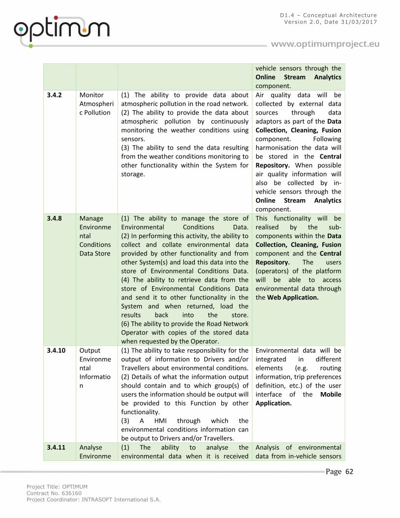
Project Title: OPTIMUM
Contract No. 636160 Project Coordinator: INTRASOFT International S.A.
Page 62
D1.4 – Conceptual Architecture
Version 2.0, Date 31/03/2017
vehicle sensors through the Online Stream Analytics component.
3.4.2 Monitor Atmospheric Pollution
(1) The ability to provide data about atmospheric pollution in the road network. (2) The ability to provide the data about atmospheric pollution by continuously monitoring the weather conditions using sensors. (3) The ability to send the data resulting from the weather conditions monitoring to other functionality within the System for storage.
Air quality data will be collected by external data sources through data adaptors as part of the Data Collection, Cleaning, Fusion component. Following harmonisation the data will be stored in the Central Repository. When possible air quality information will also be collected by in-vehicle sensors through the Online Stream Analytics component.
3.4.8 Manage Environmental Conditions Data Store
(1) The ability to manage the store of Environmental Conditions Data. (2) In performing this activity, the ability to collect and collate environmental data provided by other functionality and from other System(s) and load this data into the store of Environmental Conditions Data. (4) The ability to retrieve data from the store of Environmental Conditions Data and send it to other functionality in the System and when returned, load the results back into the store. (6) The ability to provide the Road Network Operator with copies of the stored data when requested by the Operator.
This functionality will be realised by the sub-components within the Data Collection, Cleaning, Fusion component and the Central Repository. The users (operators) of the platform will be able to access environmental data through the Web Application.
3.4.10 Output Environmental Information
(1) The ability to take responsibility for the output of information to Drivers and/or Travellers about environmental conditions. (2) Details of what the information output should contain and to which group(s) of users the information should be output will be provided to this Function by other functionality. (3) A HMI through which the environmental conditions information can be output to Drivers and/or Travellers.
Environmental data will be integrated in different elements (e.g. routing information, trip preferences definition, etc.) of the user interface of the Mobile Application.
3.4.11 Analyse Environme
(1) The ability to analyse the environmental data when it is received
Analysis of environmental data from in-vehicle sensors
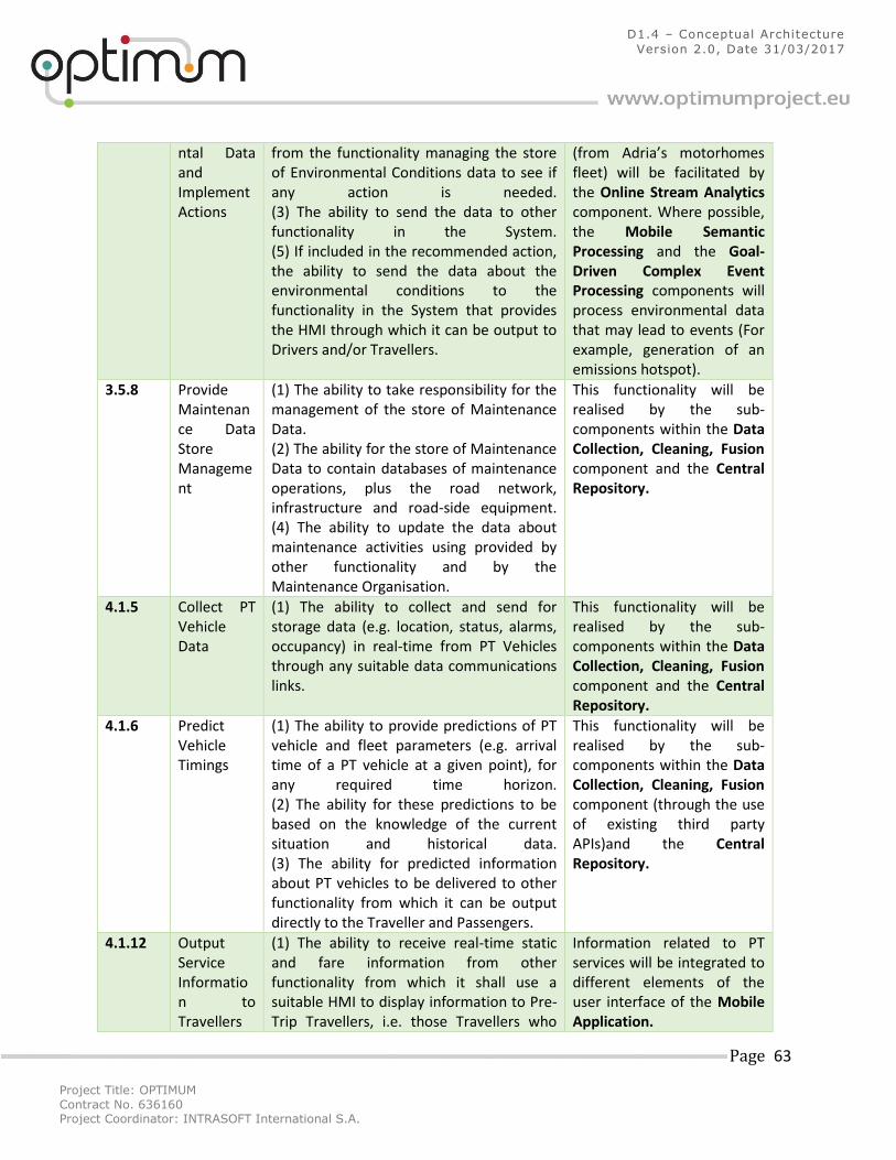
Project Title: OPTIMUM
Contract No. 636160 Project Coordinator: INTRASOFT International S.A.
Page 63
D1.4 – Conceptual Architecture
Version 2.0, Date 31/03/2017
ntal Data and Implement Actions
from the functionality managing the store of Environmental Conditions data to see if any action is needed. (3) The ability to send the data to other functionality in the System. (5) If included in the recommended action, the ability to send the data about the environmental conditions to the functionality in the System that provides the HMI through which it can be output to Drivers and/or Travellers.
(from Adria’s motorhomes fleet) will be facilitated by the Online Stream Analytics component. Where possible, the Mobile Semantic Processing and the Goal-Driven Complex Event Processing components will process environmental data that may lead to events (For example, generation of an emissions hotspot).
3.5.8 Provide Maintenance Data Store Management
(1) The ability to take responsibility for the management of the store of Maintenance Data. (2) The ability for the store of Maintenance Data to contain databases of maintenance operations, plus the road network, infrastructure and road-side equipment. (4) The ability to update the data about maintenance activities using provided by other functionality and by the Maintenance Organisation.
This functionality will be realised by the sub-components within the Data Collection, Cleaning, Fusion component and the Central Repository.
4.1.5 Collect PT Vehicle Data
(1) The ability to collect and send for storage data (e.g. location, status, alarms, occupancy) in real-time from PT Vehicles through any suitable data communications links.
This functionality will be realised by the sub-components within the Data Collection, Cleaning, Fusion component and the Central Repository.
4.1.6 Predict Vehicle Timings
(1) The ability to provide predictions of PT vehicle and fleet parameters (e.g. arrival time of a PT vehicle at a given point), for any required time horizon. (2) The ability for these predictions to be based on the knowledge of the current situation and historical data. (3) The ability for predicted information about PT vehicles to be delivered to other functionality from which it can be output directly to the Traveller and Passengers.
This functionality will be realised by the sub-components within the Data Collection, Cleaning, Fusion component (through the use of existing third party APIs)and the Central Repository.
4.1.12 Output Service Information to Travellers
(1) The ability to receive real-time static and fare information from other functionality from which it shall use a suitable HMI to display information to Pre-Trip Travellers, i.e. those Travellers who
Information related to PT services will be integrated to different elements of the user interface of the Mobile Application.
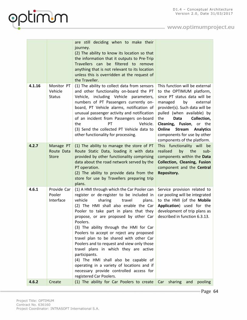
Project Title: OPTIMUM
Contract No. 636160 Project Coordinator: INTRASOFT International S.A.
Page 64
D1.4 – Conceptual Architecture
Version 2.0, Date 31/03/2017
are still deciding when to make their journey. (2) The ability to know its location so that the information that it outputs to Pre-Trip Travellers can be filtered to remove anything that is not relevant to its location unless this is overridden at the request of the Traveller.
4.1.16 Monitor PT Vehicle Status
(1) The ability to collect data from sensors and other functionality on-board the PT Vehicle, including Vehicle parameters, numbers of PT Passengers currently on-board, PT Vehicle alarms, notification of unusual passenger activity and notification of an incident from Passengers on-board the PT Vehicle. (3) Send the collected PT Vehicle data to other functionality for processing.
This function will be external to the OPTIMUM platform, since PT status data will be managed by external provider(s). Such data will be pulled (when available) by the Data Collection, Cleaning, Fusion, or the Online Stream Analytics components for use by other components of the platform.
4.2.7 Manage PT Route Data Store
(1) The ability to manage the store of PT Route Static Data, loading it with data provided by other functionality comprising data about the road network served by the PT operation. (2) The ability to provide data from the store for use by Travellers preparing trip plans.
This functionality will be realised by the sub-components within the Data Collection, Cleaning, Fusion component and the Central Repository.
4.6.1 Provide Car Pooler Interface
(1) A HMI through which the Car Pooler can register or de-register to be included in vehicle sharing travel plans. (2) The HMI shall also enable the Car Pooler to take part in plans that they propose, or are proposed by other Car Poolers. (3) The ability through the HMI for Car Poolers to accept or reject any proposed travel plan to be shared with other Car Poolers and to request and view only those travel plans in which they are active participants. (4) The HMI shall also be capable of operating in a variety of locations and if necessary provide controlled access for registered Car Poolers.
Service provision related to car pooling will be integrated to the HMI (of the Mobile Application) used for the development of trip plans as described in function 6.3.13.
4.6.2 Create (1) The ability for Car Poolers to create Car sharing and pooling
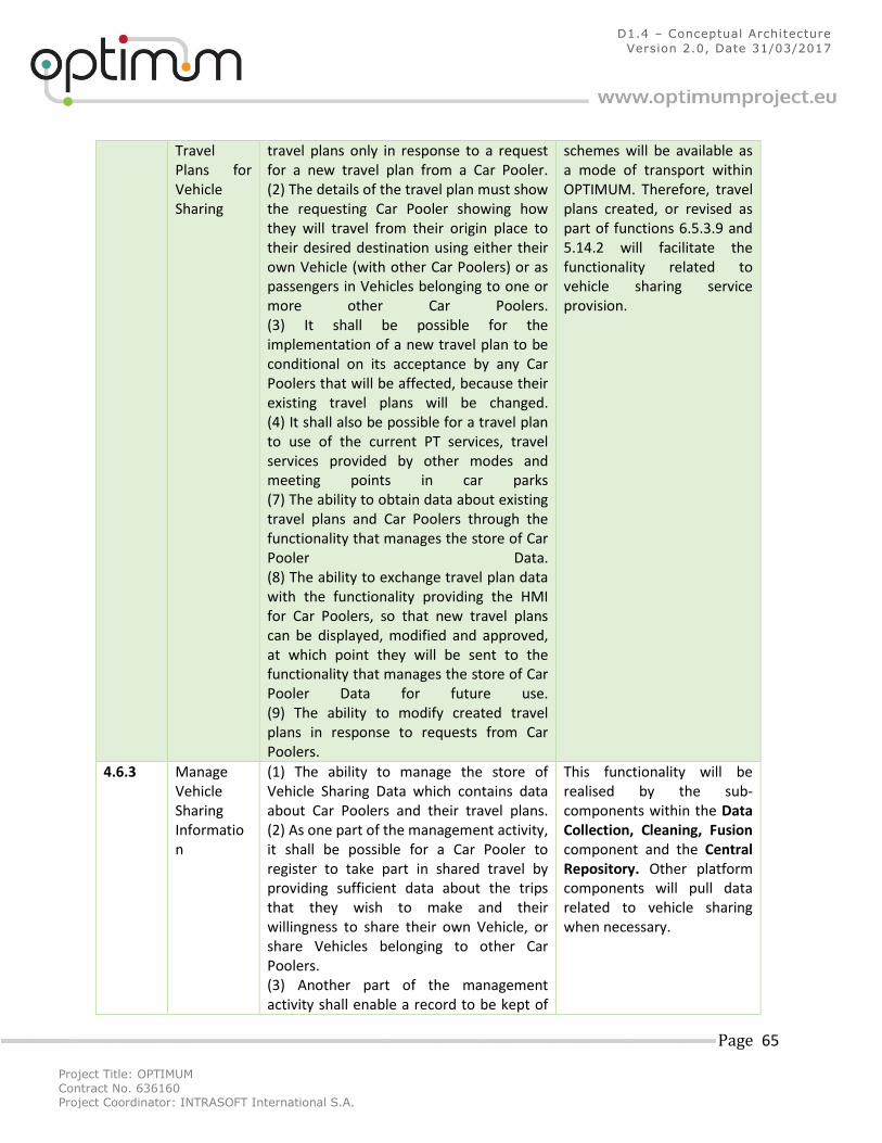
Project Title: OPTIMUM
Contract No. 636160 Project Coordinator: INTRASOFT International S.A.
Page 65
D1.4 – Conceptual Architecture
Version 2.0, Date 31/03/2017
Travel Plans for Vehicle Sharing
travel plans only in response to a request for a new travel plan from a Car Pooler. (2) The details of the travel plan must show the requesting Car Pooler showing how they will travel from their origin place to their desired destination using either their own Vehicle (with other Car Poolers) or as passengers in Vehicles belonging to one or more other Car Poolers. (3) It shall be possible for the implementation of a new travel plan to be conditional on its acceptance by any Car Poolers that will be affected, because their existing travel plans will be changed. (4) It shall also be possible for a travel plan to use of the current PT services, travel services provided by other modes and meeting points in car parks (7) The ability to obtain data about existing travel plans and Car Poolers through the functionality that manages the store of Car Pooler Data. (8) The ability to exchange travel plan data with the functionality providing the HMI for Car Poolers, so that new travel plans can be displayed, modified and approved, at which point they will be sent to the functionality that manages the store of Car Pooler Data for future use. (9) The ability to modify created travel plans in response to requests from Car Poolers.
schemes will be available as a mode of transport within OPTIMUM. Therefore, travel plans created, or revised as part of functions 6.5.3.9 and 5.14.2 will facilitate the functionality related to vehicle sharing service provision.
4.6.3 Manage Vehicle Sharing Information
(1) The ability to manage the store of Vehicle Sharing Data which contains data about Car Poolers and their travel plans. (2) As one part of the management activity, it shall be possible for a Car Pooler to register to take part in shared travel by providing sufficient data about the trips that they wish to make and their willingness to share their own Vehicle, or share Vehicles belonging to other Car Poolers. (3) Another part of the management activity shall enable a record to be kept of
This functionality will be realised by the sub-components within the Data Collection, Cleaning, Fusion component and the Central Repository. Other platform components will pull data related to vehicle sharing when necessary.
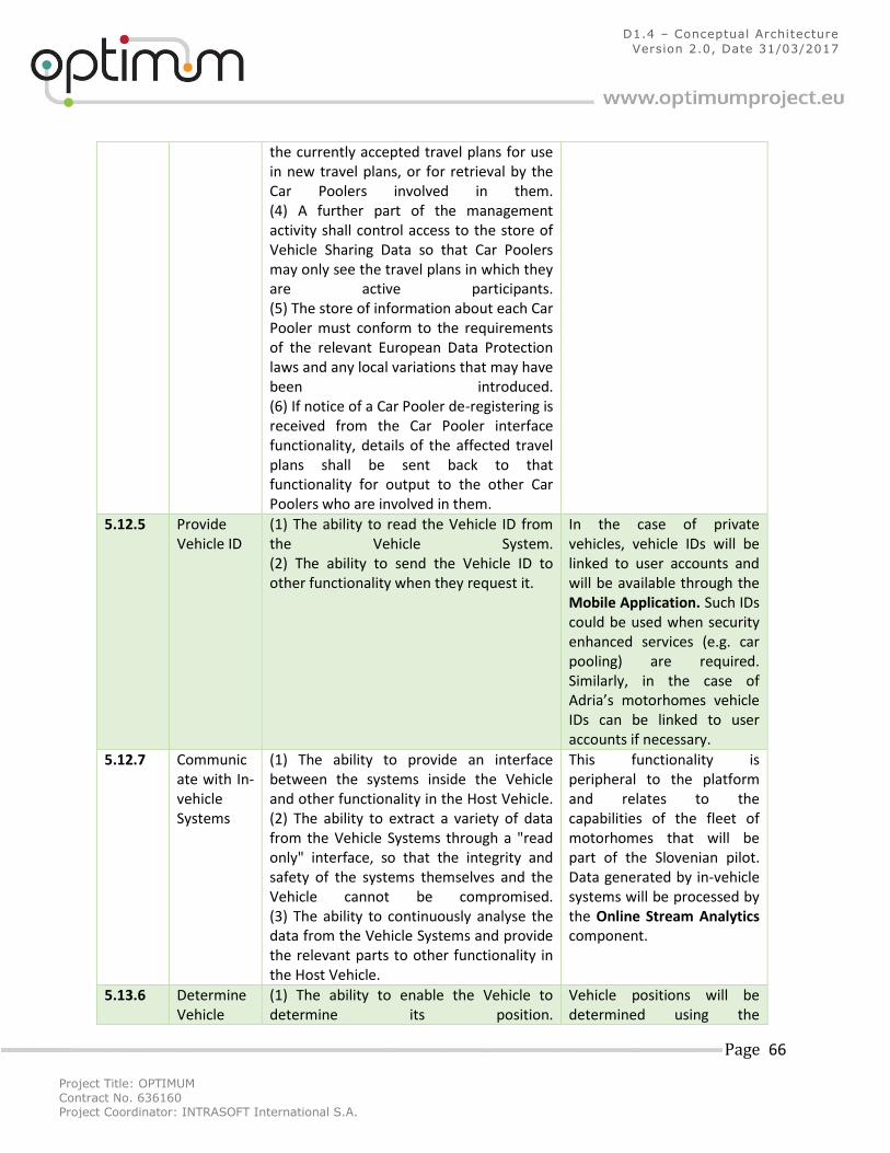
Project Title: OPTIMUM
Contract No. 636160 Project Coordinator: INTRASOFT International S.A.
Page 66
D1.4 – Conceptual Architecture
Version 2.0, Date 31/03/2017
the currently accepted travel plans for use in new travel plans, or for retrieval by the Car Poolers involved in them. (4) A further part of the management activity shall control access to the store of Vehicle Sharing Data so that Car Poolers may only see the travel plans in which they are active participants. (5) The store of information about each Car Pooler must conform to the requirements of the relevant European Data Protection laws and any local variations that may have been introduced. (6) If notice of a Car Pooler de-registering is received from the Car Pooler interface functionality, details of the affected travel plans shall be sent back to that functionality for output to the other Car Poolers who are involved in them.
5.12.5 Provide Vehicle ID
(1) The ability to read the Vehicle ID from the Vehicle System. (2) The ability to send the Vehicle ID to other functionality when they request it.
In the case of private vehicles, vehicle IDs will be linked to user accounts and will be available through the Mobile Application. Such IDs could be used when security enhanced services (e.g. car pooling) are required. Similarly, in the case of Adria’s motorhomes vehicle IDs can be linked to user accounts if necessary.
5.12.7 Communicate with In-vehicle Systems
(1) The ability to provide an interface between the systems inside the Vehicle and other functionality in the Host Vehicle. (2) The ability to extract a variety of data from the Vehicle Systems through a "read only" interface, so that the integrity and safety of the systems themselves and the Vehicle cannot be compromised. (3) The ability to continuously analyse the data from the Vehicle Systems and provide the relevant parts to other functionality in the Host Vehicle.
This functionality is peripheral to the platform and relates to the capabilities of the fleet of motorhomes that will be part of the Slovenian pilot. Data generated by in-vehicle systems will be processed by the Online Stream Analytics component.
5.13.6 Determine Vehicle
(1) The ability to enable the Vehicle to determine its position.
Vehicle positions will be determined using the
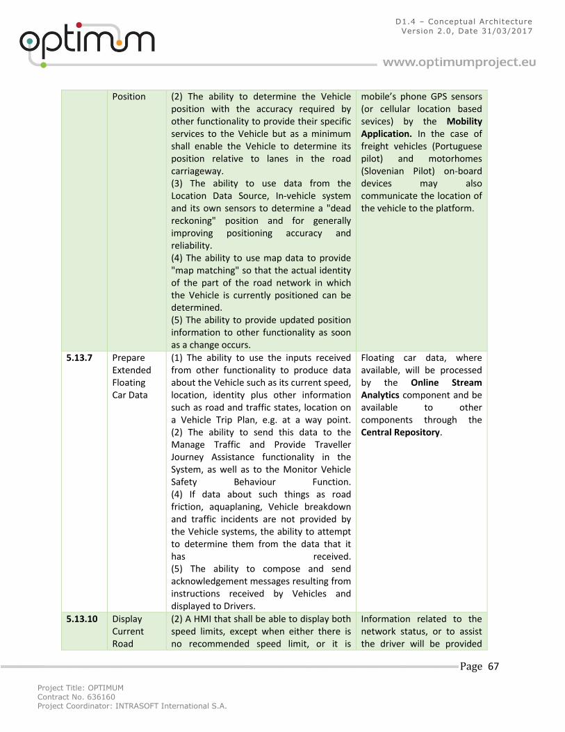
Project Title: OPTIMUM
Contract No. 636160 Project Coordinator: INTRASOFT International S.A.
Page 67
D1.4 – Conceptual Architecture
Version 2.0, Date 31/03/2017
Position (2) The ability to determine the Vehicle position with the accuracy required by other functionality to provide their specific services to the Vehicle but as a minimum shall enable the Vehicle to determine its position relative to lanes in the road carriageway. (3) The ability to use data from the Location Data Source, In-vehicle system and its own sensors to determine a "dead reckoning" position and for generally improving positioning accuracy and reliability. (4) The ability to use map data to provide "map matching" so that the actual identity of the part of the road network in which the Vehicle is currently positioned can be determined. (5) The ability to provide updated position information to other functionality as soon as a change occurs.
mobile’s phone GPS sensors (or cellular location based sevices) by the Mobility Application. In the case of freight vehicles (Portuguese pilot) and motorhomes (Slovenian Pilot) on-board devices may also communicate the location of the vehicle to the platform.
5.13.7 Prepare Extended Floating Car Data
(1) The ability to use the inputs received from other functionality to produce data about the Vehicle such as its current speed, location, identity plus other information such as road and traffic states, location on a Vehicle Trip Plan, e.g. at a way point. (2) The ability to send this data to the Manage Traffic and Provide Traveller Journey Assistance functionality in the System, as well as to the Monitor Vehicle Safety Behaviour Function. (4) If data about such things as road friction, aquaplaning, Vehicle breakdown and traffic incidents are not provided by the Vehicle systems, the ability to attempt to determine them from the data that it has received. (5) The ability to compose and send acknowledgement messages resulting from instructions received by Vehicles and displayed to Drivers.
Floating car data, where available, will be processed by the Online Stream Analytics component and be available to other components through the Central Repository.
5.13.10 Display Current Road
(2) A HMI that shall be able to display both speed limits, except when either there is no recommended speed limit, or it is
Information related to the network status, or to assist the driver will be provided
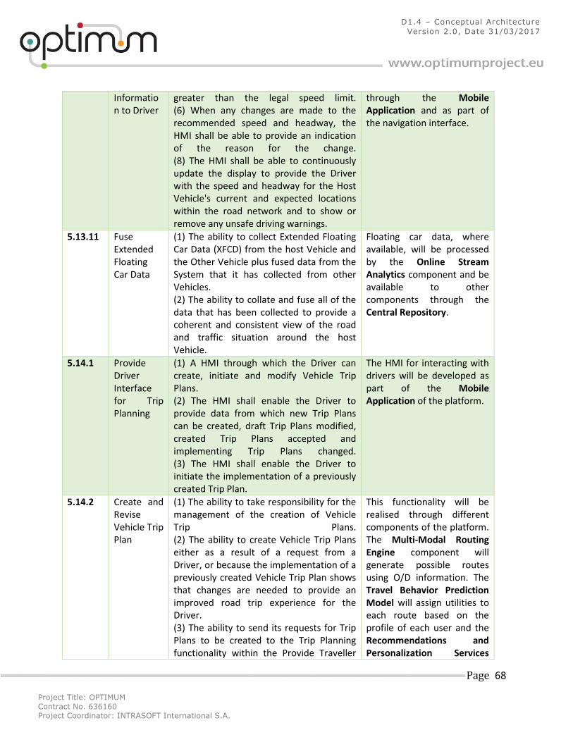
Project Title: OPTIMUM
Contract No. 636160 Project Coordinator: INTRASOFT International S.A.
Page 68
D1.4 – Conceptual Architecture
Version 2.0, Date 31/03/2017
Information to Driver
greater than the legal speed limit. (6) When any changes are made to the recommended speed and headway, the HMI shall be able to provide an indication of the reason for the change. (8) The HMI shall be able to continuously update the display to provide the Driver with the speed and headway for the Host Vehicle's current and expected locations within the road network and to show or remove any unsafe driving warnings.
through the Mobile Application and as part of the navigation interface.
5.13.11 Fuse Extended Floating Car Data
(1) The ability to collect Extended Floating Car Data (XFCD) from the host Vehicle and the Other Vehicle plus fused data from the System that it has collected from other Vehicles. (2) The ability to collate and fuse all of the data that has been collected to provide a coherent and consistent view of the road and traffic situation around the host Vehicle.
Floating car data, where available, will be processed by the Online Stream Analytics component and be available to other components through the Central Repository.
5.14.1 Provide Driver Interface for Trip Planning
(1) A HMI through which the Driver can create, initiate and modify Vehicle Trip Plans. (2) The HMI shall enable the Driver to provide data from which new Trip Plans can be created, draft Trip Plans modified, created Trip Plans accepted and implementing Trip Plans changed. (3) The HMI shall enable the Driver to initiate the implementation of a previously created Trip Plan.
The HMI for interacting with drivers will be developed as part of the Mobile Application of the platform.
5.14.2 Create and Revise Vehicle Trip Plan
(1) The ability to take responsibility for the management of the creation of Vehicle Trip Plans. (2) The ability to create Vehicle Trip Plans either as a result of a request from a Driver, or because the implementation of a previously created Vehicle Trip Plan shows that changes are needed to provide an improved road trip experience for the Driver. (3) The ability to send its requests for Trip Plans to be created to the Trip Planning functionality within the Provide Traveller
This functionality will be realised through different components of the platform. The Multi-Modal Routing Engine component will generate possible routes using O/D information. The Travel Behavior Prediction Model will assign utilities to each route based on the profile of each user and the Recommendations and Personalization Services
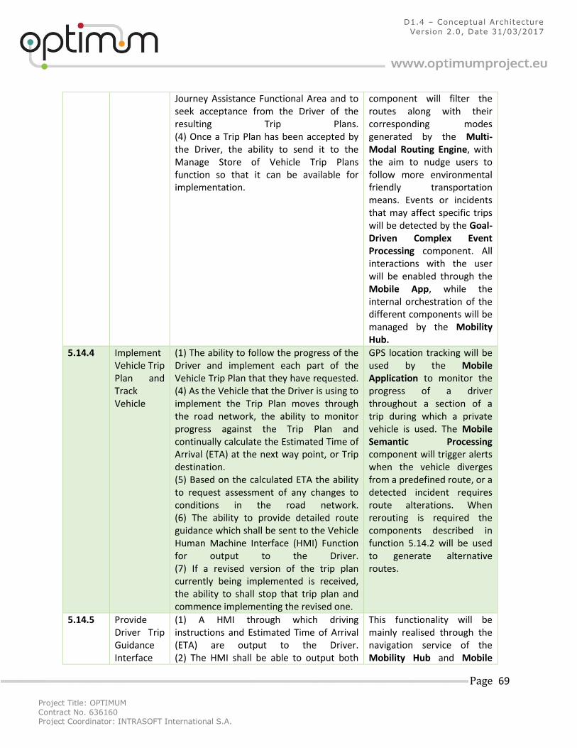
Project Title: OPTIMUM
Contract No. 636160 Project Coordinator: INTRASOFT International S.A.
Page 69
D1.4 – Conceptual Architecture
Version 2.0, Date 31/03/2017
Journey Assistance Functional Area and to seek acceptance from the Driver of the resulting Trip Plans. (4) Once a Trip Plan has been accepted by the Driver, the ability to send it to the Manage Store of Vehicle Trip Plans function so that it can be available for implementation.
component will filter the routes along with their corresponding modes generated by the Multi-Modal Routing Engine, with the aim to nudge users to follow more environmental friendly transportation means. Events or incidents that may affect specific trips will be detected by the Goal-Driven Complex Event Processing component. All interactions with the user will be enabled through the Mobile App, while the internal orchestration of the different components will be managed by the Mobility Hub.
5.14.4 Implement Vehicle Trip Plan and Track Vehicle
(1) The ability to follow the progress of the Driver and implement each part of the Vehicle Trip Plan that they have requested. (4) As the Vehicle that the Driver is using to implement the Trip Plan moves through the road network, the ability to monitor progress against the Trip Plan and continually calculate the Estimated Time of Arrival (ETA) at the next way point, or Trip destination. (5) Based on the calculated ETA the ability to request assessment of any changes to conditions in the road network. (6) The ability to provide detailed route guidance which shall be sent to the Vehicle Human Machine Interface (HMI) Function for output to the Driver. (7) If a revised version of the trip plan currently being implemented is received, the ability to shall stop that trip plan and commence implementing the revised one.
GPS location tracking will be used by the Mobile Application to monitor the progress of a driver throughout a section of a trip during which a private vehicle is used. The Mobile Semantic Processing component will trigger alerts when the vehicle diverges from a predefined route, or a detected incident requires route alterations. When rerouting is required the components described in function 5.14.2 will be used to generate alternative routes.
5.14.5 Provide Driver Trip Guidance Interface
(1) A HMI through which driving instructions and Estimated Time of Arrival (ETA) are output to the Driver. (2) The HMI shall be able to output both
This functionality will be mainly realised through the navigation service of the Mobility Hub and Mobile
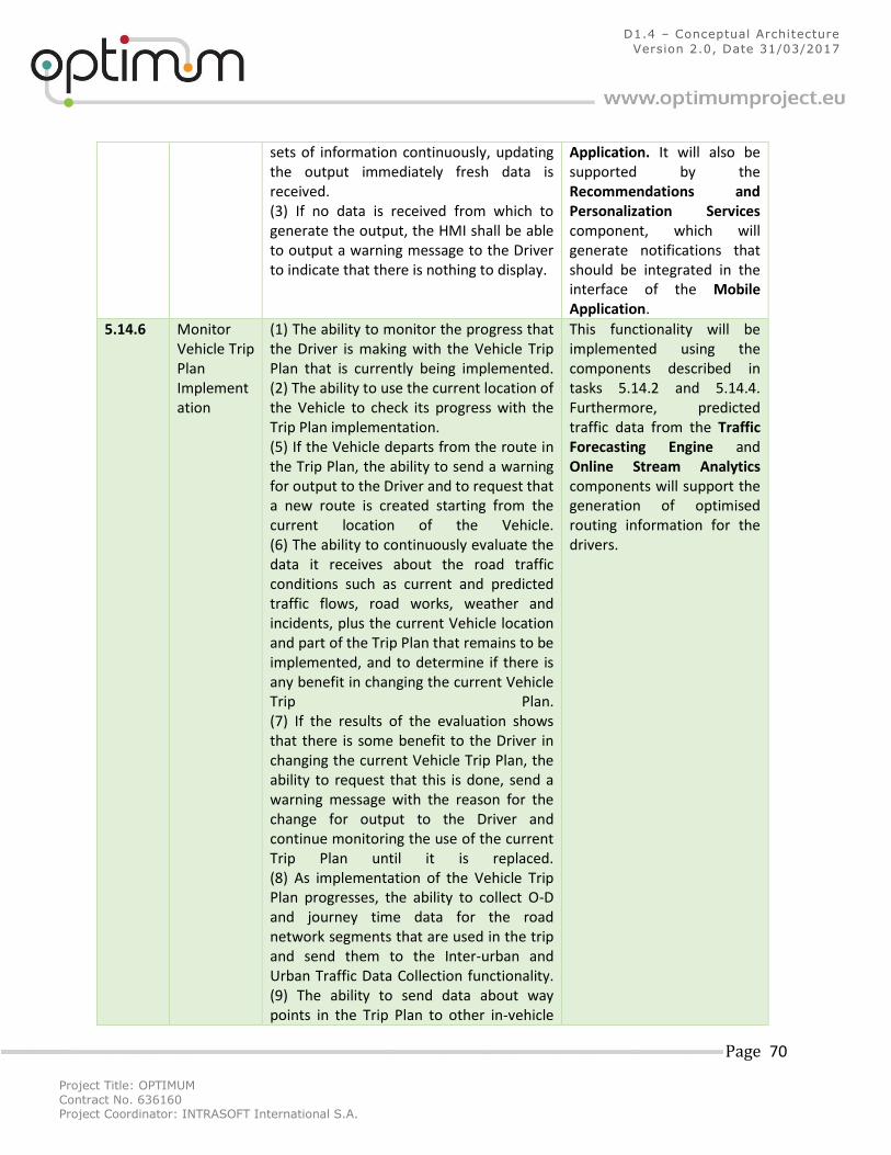
Project Title: OPTIMUM
Contract No. 636160 Project Coordinator: INTRASOFT International S.A.
Page 70
D1.4 – Conceptual Architecture
Version 2.0, Date 31/03/2017
sets of information continuously, updating the output immediately fresh data is received. (3) If no data is received from which to generate the output, the HMI shall be able to output a warning message to the Driver to indicate that there is nothing to display.
Application. It will also be supported by the Recommendations and Personalization Services component, which will generate notifications that should be integrated in the interface of the Mobile Application.
5.14.6 Monitor Vehicle Trip Plan Implementation
(1) The ability to monitor the progress that the Driver is making with the Vehicle Trip Plan that is currently being implemented. (2) The ability to use the current location of the Vehicle to check its progress with the Trip Plan implementation. (5) If the Vehicle departs from the route in the Trip Plan, the ability to send a warning for output to the Driver and to request that a new route is created starting from the current location of the Vehicle. (6) The ability to continuously evaluate the data it receives about the road traffic conditions such as current and predicted traffic flows, road works, weather and incidents, plus the current Vehicle location and part of the Trip Plan that remains to be implemented, and to determine if there is any benefit in changing the current Vehicle Trip Plan. (7) If the results of the evaluation shows that there is some benefit to the Driver in changing the current Vehicle Trip Plan, the ability to request that this is done, send a warning message with the reason for the change for output to the Driver and continue monitoring the use of the current Trip Plan until it is replaced. (8) As implementation of the Vehicle Trip Plan progresses, the ability to collect O-D and journey time data for the road network segments that are used in the trip and send them to the Inter-urban and Urban Traffic Data Collection functionality. (9) The ability to send data about way points in the Trip Plan to other in-vehicle
This functionality will be implemented using the components described in tasks 5.14.2 and 5.14.4. Furthermore, predicted traffic data from the Traffic Forecasting Engine and Online Stream Analytics components will support the generation of optimised routing information for the drivers.
Project Title: OPTIMUM
Contract No. 636160 Project Coordinator: INTRASOFT International S.A.
Page 71
D1.4 – Conceptual Architecture
Version 2.0, Date 31/03/2017
functionality for inclusion in Extended Floating Car Data (XFCD).
5.14.7 Manage Store of Vehicle Trip Plans
(1) The ability to manage the store of Vehicle Trip Plans Data. (2) The ability to ensure that all data sent to the store is stored in a coherent and logical manner. (3) The ability to read data from the store as and when requested. (4) The ability to enable Trip Plans to be created in advance of their use and for the same Trip Plan to be used whenever the Host Vehicle is used on the same journey, even though it may be driven by a different Driver. (5) The ability to carry out its activities in such a way that they do not interfere with one another and that the integrity of the data being stored and read is preserved.
This functionality will be realised by the sub-components within the Data Collection, Cleaning, Fusion component and the Central Repository.
6.3.10 Implement Trip Plan and Track Traveller
(1) The ability to follow the progress of the Traveller as they move along the previously planned and requested trip and implement each part of the trip plan using the stored plan data. (3) The ability to follow the time schedule in the trip plan. (4) If required by the trip plan, the ability to provide detailed route guidance which it shall send to the Traveller Interface Function for output to the Traveller. (5) If the a revised version of the trip plan currently being implemented is received, the ability to stop current trip plan and commence implementing the revised one from the current location of the Traveller.
The navigation sub-component of the Mobility Hub will realise detailed route guidance for the traveller. The navigation interface will be integrated as part of the Mobile Application, which will handle all interactions with the traveller. Changes to such guidance may be instigated by the system’s abilities described in function 6.3.11.
6.3.11 Monitor Trip Plan Implementation for Traveller
(1) The ability to receive data about the current location of the Traveller so that progress with the current trip plan can be monitored until either the trip is completed, or a new trip plan is produced. (2) The ability to continuously evaluate the data that is received about travel conditions such as current and predicted traffic flows, road works, weather, incidents and PT services.
GPS location tracking will be used by the Mobile Application to monitor the progress of a driver throughout a section of a trip during which different modes are being used. The Mobile Semantic Processing component will trigger alerts when the traveller diverges
Project Title: OPTIMUM
Contract No. 636160 Project Coordinator: INTRASOFT International S.A.
Page 72
D1.4 – Conceptual Architecture
Version 2.0, Date 31/03/2017
(3) The ability to use the results of the evaluation of travel conditions and the current location of the Traveller to determine if there will be benefit to the Traveller from changing the trip plan and to request that a new trip plan is produced if such a benefit is found. (4) The ability to collect O-D and journey time data for the road network segments that are used in the trip plan and send them to the Inter-urban and Urban Traffic Data Collection functionality. (5) At the end of the trip, the ability to collect the data about the complete performance of the trip and send it to the Performance Evaluation functionality.
from a predefined trip configuration, or a detected incident requires changes to the current plan. When plan revision is required the components described in function 6.5.3.9 will be used to generate alternative trip plans.
6.3.12 Manage Revised Trip Plan Creation for Traveller
(1) The ability to manage the production of revised trip plans whenever a change becomes necessary to the trip plan that is currently being implemented. (2) The ability to request changes to the trip plan either because it is not providing the best possible trip for the Traveller, or because the Traveller requests the change. (3) Once the request has been received, the ability to send it to the Trip Planning functionality for the creation of a new trip plan that starts from the last known location of the Traveller. (4) When the revised trip plan is received, the ability to use the Provide Traveller Trip Interface Function to establish that either the Traveller accepts the revised trip plan, or wishes to have further changes made. (5) Once the revised trip plan has been accepted, the ability to send it to the Manage Store of Trip Plan Data Function and to inform the Implement Trip Plan and Track Traveller Function that a revised trip plan is about to be provided.
When plan revision is required the components described in function 6.5.3.9 will be used to generate alternative trip plans. All interactions with the traveller, for the development of revised trip plans, will be enabled through HMIs developed as part of the Mobile Application.
6.3.13 Provide Traveller Trip Interface
(1) A HMI through which the Traveller can request the implementation of a trip plan, be given trip navigation instructions or manage changes to the trip plan that is currently being implemented.
The Mobile Application will provide the HMI necessary to facilitate all trip planning and trip management interactions with the
Project Title: OPTIMUM
Contract No. 636160 Project Coordinator: INTRASOFT International S.A.
Page 73
D1.4 – Conceptual Architecture
Version 2.0, Date 31/03/2017
(2) The ability for the HMI to output in whatever form best suits the Traveller the instructions for implementing the trip plan that are provided by the Implement Trip Plan and Track Traveller function. (3) If a proposal is received for revising the trip plan that is being implemented, the ability of the HMI to display details of the proposed changes to the Traveller and send back the response that is received to the Manage Revised Trip Plan Creation for Traveller function. (4) The ability for the HMI to receive requests for changes to the trip plan from the Traveller and also send them to the Manage Revised Trip Plan Creation for Traveller function.
traveller. This will be supported by personalised visualisations, based on user profiles, by the Recommendations and Personalization Services and Travel Behavior Prediction Model components.
6.5.3.3 Collect PT Data
(1) The ability to collect Public Transport travel data for use in the preparation of trip plans for Travellers. (2) The ability to collect the data as it arrives from functionality in the Manage Public Transport Operations Functional Area. (3) The ability to load the data that has been collected into the store of PT Trip Planning Data and to manage all of the data in that store.
This functionality will be realised by the sub-components within the Data Collection, Cleaning, Fusion component and the Central Repository.
6.5.3.8 Collect Data About Road Traffic
(1) The ability to collect road based travel data for use in the preparation of trip plans for Travellers, as well as for Freight and Emergency Vehicles. (2) The ability to collect the data as it arrives from functionality in the Manage Traffic Functional Area. (3) The ability to load the collected data into the store of Road Trip Planning Data and to manage all of the data in that store.
This functionality will be realised by the sub-components within the Data Collection, Cleaning, Fusion component and the Central Repository.
6.5.3.9 Plan Trip Details
(1) The ability to manage the production of trip plans based on data provided by the Traveller through functionality in other parts of the system. (2) The ability to prepare trip plans for journeys that are either one way, or for a return trip (including weeks/months
This functionality will be realised through different components of the platform. The Multi-Modal Routing Engine component will generate possible trips using O/D information. The Travel
Project Title: OPTIMUM
Contract No. 636160 Project Coordinator: INTRASOFT International S.A.
Page 74
D1.4 – Conceptual Architecture
Version 2.0, Date 31/03/2017
ahead), and that take advantage of late opening hours, special facilities etc. (3) The ability to check the criteria provided by the Traveller and obtain information for the specified modes to be used in the requested trip, but taking account of the trip planning criteria that have been set up by the Travel Information Operator. (4) The ability to use data from the store of Road Trip Planning Data and/or the store of PT Trip Planning Data, plus also to collect information about Points of Interest (POI) and Personal Services (PS) from External Service Providers. (5) Where specified by the Traveller the ability to request information about the services provided by other transport modes, tolls plus other charges if they will need to be paid in order to complete the proposed trip, and to pass all of this information on to the Provide Traveller Information functionality. (6) The ability to create trip plans for cyclists and pedestrians using the road network data and related perturbations, but disregarding traffic incident information. (7) The ability to revise a part completed trip plan when a Traveller departs in any way from its contents, or travel conditions change, starting from the current Traveller location and mode of travel. (8) The ability to exchange journey time data for each segment of the road network with its implementation in other devices and to plan trips when the only traffic related data that is available this journey time data.
Behavior Prediction Model will assign utilities to each route based on the profile of each user and the Recommendations and Personalization Services component will filter the routes along with their corresponding modes generated by the Multi-Modal Routing Engine, with the aim to nudge users to follow more environmental friendly transportation means. Events or incidents that may affect specific trips will be detected by the Goal-Driven Complex Event Processing component. All interactions with the user will be enabled through the Mobile App, while the internal orchestration of the different components will be managed by the Mobility Hub.
6.5.10 Provide Traveller Trip Planning Interface
(1) A HMI through which the Traveller can initiate and manage the trip planning process. (2) Using the HMI, the ability of the Traveller to define the parameters that are to be used to plan a trip, including origin,
All interactions with the traveller, for the development of trip plans, will be enabled through HMIs developed as part of the Mobile Application. Sub-
Project Title: OPTIMUM
Contract No. 636160 Project Coordinator: INTRASOFT International S.A.
Page 75
D1.4 – Conceptual Architecture
Version 2.0, Date 31/03/2017
destination, places to be visited during the trip before the destination is reached (way points, transport modes to be used, departure time, arrival time, services to be booked, and whatever else is deemed interesting for trip satisfaction. (3) The ability for the Traveller to use the HMI to request that these parameters are entered into the store of General Trip Preferences Data or to use data in this store to supplement that being provided for a particular trip. (4) When complete, the ability to send the requirements to the Trip Planning functionality so that the trip plan can be prepared. (5) The ability to use the HMI to present the prepared trip plan to the Traveller and for the Traveller to be able to refine any of the requirements and re-plan the trip until it fulfils their needs in an iterative way. (6) The ability to store successive trip plans internally so that they can be re-called by the Traveller if later versions turn out to be unsatisfactory. (8) The ability for the Traveller to use the HMI to reject a trip plan and close the trip planning activity at any time and to delete any requirements that have been provided.
components of the Mobility Hub will orchestrate the operation of the Multimodal Routing Engine, Recommendation and Personalisation Services and Traveler Behavior Predictions Model components for the generation of the plans as described in function 6.5.3.9.
6.7.1 Define Traveller's General Trip Preferences
(1) The ability for the Traveller to specify a set of factual data to be used as General Trip Preferences (GTP) for use each time they want to plan a trip. (2) There shall be no requirement for the Traveller to do this more than once and the data shall be used as a preparation to full personalisation. (3) Once a planned trip has been completed, the ability to ask the Traveller for any comments on the performance of the trip and any changes that are needed to the GTP data. (4) The ability to enable the Traveller to receive an output of their current GTP data and to amend that data, even if this is not
User specific trip preference data will be entered and updated through the Mobile Application. The Recommendations and Personalization services component will define a list of the preferences that can be setup by the user.
Project Title: OPTIMUM
Contract No. 636160 Project Coordinator: INTRASOFT International S.A.
Page 76
D1.4 – Conceptual Architecture
Version 2.0, Date 31/03/2017
the result of the performance of a planned trip.
6.7.2 Evaluate Trip After Completion
(1) The ability to evaluate the success of the trip planning and implementation. (2) The evaluation shall be based on data provided by the Support Trip functionality and optional input from the Traveller collected after the trip has been completed. (3) The ability to collect any required input as comments on the trip and on the support given using the Define Traveller's General Trip Preferences functionality.
The Recommendations and Personalization services component will define the user interface elements to be used for evaluating their outputs, i.e. personalized visualizations/messages/notifications and filtered routes. The aforementioned user interface elements will be implemented as part of the Mobile Application. In addition the Traveller Behavior Predictions Model will update the user profile based on post trip evaluation input.
6.7.4 Manage General Trip Preferences Storage
(1) The ability to manage the store of General Trip Preferences (GTP) Data. (2) The data in this store shall be available for Travellers to use for every trip that they plan. (3) The ability to keep the preferences for each Traveller separate and only allow the data for each Traveller to be entered, accessed and updated by the Traveller that owns it.
This functionality will be realised by the sub-components within the Data Collection, Cleaning, Fusion component and the Central Repository.
6.8.1 Manage Store of Trip Plan Data
(1) The ability to manage the store of Private Trip Plan Data. (2) The store shall contain descriptions of all of the trip plans produced by each Traveller. (3) The ability to update the store contents whenever a Traveller prepares and finally accepts a new trip plan. (4) The ability to retrieve a prepared trip plan whenever the Traveller decides to implement a trip. (5) When a trip plan is retrieved for implementation, its description shall be sent to the Implement Trip Plan and Track Traveller Function and to the Monitor Trip Plan Implementation for Traveller
This functionality will be realised by the sub-components within the Data Collection, Cleaning, Fusion component and the Central Repository. The interaction with the user as part of the trip planning process will be facilitated by the Mobile Application.
Project Title: OPTIMUM
Contract No. 636160 Project Coordinator: INTRASOFT International S.A.
Page 77
D1.4 – Conceptual Architecture
Version 2.0, Date 31/03/2017
Function.
4.1 FRAME ITS Extensions As some of the indented functionality of the OPTIMUM platform goes beyond the scope of the
FRAME ITS architecture a number of proposed extensions have been identified and are listed in
Table 6.
Table 6: OPTIMUM extensions to FRAME ITS
FRAME ITS Architecture Functionality
Proposed Extension
3.2.12 Detect Incidents from Data The envisaged functionality of the Goal-Driven Complex Event Processing and Mobile Semantic Processing components will extend existing functionality by dynamically detecting or producing patterns from anticipatory services (predictions). Furthermore, sensory detections will go beyond traffic sensors to include real-time sensor data from the mobile phones.
1.3.5 Compute Service Fee This specific low-level function will be extended by the use of additional inputs for the dynamic calculation of tolls for freight vehicles. Such inputs will go beyond traffic conditions and include information such as predicted traffic flows, weather conditions, seasonality, environmental factors, maintenance of the highways and other relevant data.
3.1.1.13 Predict Short & Medium Term Urban Conditions 3.1.2.15 Predict Short & Medium Term Inter-urban Conditions
The Traffic Forecasting Engine supported by the Online Stream Analytics and Social Miner components will enhance the existing functionality by the use of data from social networks in order to integrate crowd sourcing and traffic data for more accurate predictions.
6.3.10 Implement Trip Plan and Track Traveller
The Mobile Semantic Processing component will proactively detect the mode used by the traveller in order to trigger events when corrective actions, due to divergent from planned trips, need to take place.
6.7.1 Define Traveller's General Trip Preferences
The Recommendations and Personalization services component will enhance general trip preference user data by identifying user specific persuasion strategies that can be adopted for optimizing trip information
Project Title: OPTIMUM
Contract No. 636160 Project Coordinator: INTRASOFT International S.A.
Page 78
D1.4 – Conceptual Architecture
Version 2.0, Date 31/03/2017
based on different indicators (e.g carbon footprint, physical exercise, etc.).
6.5.3.9 Plan Trip Details 5.14.2 Create and Revise Vehicle Trip Plan
The System Aware Optimisation subcomponent of the Multi-Modal Routing Engine will optimize individual route provision based on global system objectives. Furthermore, the Online Stream Analytics component will proactively detect the purpose and destination of a trip in order to support the provision of personalized information to the users. Finally, the Mobile Semantic Processing and Social Miner components will aim to detect the physical and emotional status of a user in order to advise persuasion actions that best match a user’s current status.
5 OPTIMUM Components Specifications 5.1 Observe Layer 5.1.1 Data Collection, Cleaning and Fusion Purpose
The OPTIMUM data collection, cleaning and fusion infrastructure will be responsible for the
extraction, cleaning and harmonization of data that exist in various data sources, and it will rely
on standards to harmonize some data sources, such as Datex II6 for traffic-related information.
This component will have to be able to cope with data sources characterized by high
throughput, intensity and heterogeneity.
Description
ETL tools will be developed to gather, clean and store data into a central repository. The data
collection, cleaning and fusion infrastructure will facilitate the data fusion into common
schema. Recent data collection technologies will enable access to various analyses, such as
traffic sensor data analysis, and allow for the identification of transport modes and the study of
user habits, thus deriving information on the users’ and the network’s current situation. In
addition, Real-time interaction with the OPTIMUM platform will facilitate behavioral data
collection from travelers to enable development of robust methodologies and models for
demand analysis of multi-modal travel.
The data collection, transformation and harmonization module will have to be able to collect
data in different formats, such as CSV, Excel spreadsheets and JSON and XML among others,
6 http://www.datex2.eu
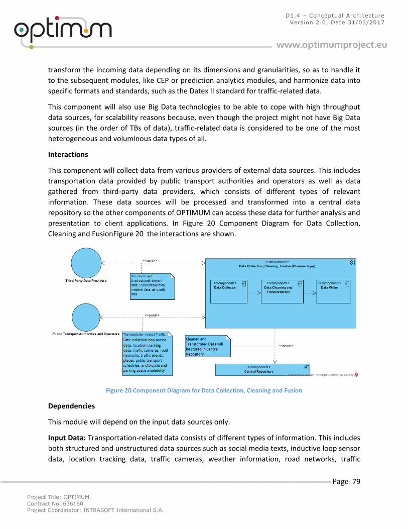
Project Title: OPTIMUM
Contract No. 636160 Project Coordinator: INTRASOFT International S.A.
Page 79
D1.4 – Conceptual Architecture
Version 2.0, Date 31/03/2017
transform the incoming data depending on its dimensions and granularities, so as to handle it
to the subsequent modules, like CEP or prediction analytics modules, and harmonize data into
specific formats and standards, such as the Datex II standard for traffic-related data.
This component will also use Big Data technologies to be able to cope with high throughput
data sources, for scalability reasons because, even though the project might not have Big Data
sources (in the order of TBs of data), traffic-related data is considered to be one of the most
heterogeneous and voluminous data types of all.
Interactions
This component will collect data from various providers of external data sources. This includes
transportation data provided by public transport authorities and operators as well as data
gathered from third-party data providers, which consists of different types of relevant
information. These data sources will be processed and transformed into a central data
repository so the other components of OPTIMUM can access these data for further analysis and
presentation to client applications. In Figure 20 Component Diagram for Data Collection,
Cleaning and FusionFigure 20 the interactions are shown.
Figure 20 Component Diagram for Data Collection, Cleaning and Fusion
Dependencies
This module will depend on the input data sources only.
Input Data: Transportation-related data consists of different types of information. This includes
both structured and unstructured data sources such as social media texts, inductive loop sensor
data, location tracking data, traffic cameras, weather information, road networks, traffic
Project Title: OPTIMUM
Contract No. 636160 Project Coordinator: INTRASOFT International S.A.
Page 80
D1.4 – Conceptual Architecture
Version 2.0, Date 31/03/2017
events, places of interest, public transport schedules, and bicycle and parking space availability.
It is expected that some of these data sources will be characterized as Big data sources.
Output Data: Cleaned, transformed and harmonized data.
Functions: Functions to access services endpoints, fetch data records, clean and transform the
data by processing several data attributes, harmonize data to the contemplated formats and
standards, and store the transformed data into a central data repository.
Assumption: Data provided by public transport authorities, operators as well as third-party
data providers are all accessible and their Web services are up and running.
Interfaces
Collecting data from the several providers requires direct access to their resources through
REST endpoint calls and SOAP Web service adaptors. Storing the transformed row data in the
back-end repository will be achieved through SQL and NoSQL write operations. Furthermore, it
is intended that generic data adaptors for some standards, such as Datex II, will be developed,
in order for third-party and future companies that wish to use the OPTIMUM platform and have
their data formatted to these standards, will be able to provide their data in a “plug-and-play”
fashion. These interfaces must be able to cope with high throughput data sources.
5.1.2 Central Repository
5.1.2.1 MongoDB
Purpose
MongoDB is an open source document database which provides long term storage and fast
(indexed) geospatial and text search.
Description
MongoDB is a NoSQL database that stores data using a flexible document data model.
Document is a data structure composed of field and value pairs. MongoDB documents are
similar to JSON objects. The values of fields may include other documents, arrays, and arrays of
documents. MongoDB provides high performance, high availability, and automatic scaling. It
can support embedded data models in its structure reducing I/O activity on database system. It
has indexes that support faster queries and can include keys from embedded documents and
arrays. In the framework of MongoDB a set of servers can be used (replica set) that hold the
same data. This replication facility can provide automatic failover and data redundancy. Also
MongoDB can scale horizontally, distributing its datasets and load across a cluster of machines.
It is appropriate for storing big quantities of data and is more scalable compared to Postgres.
Project Title: OPTIMUM
Contract No. 636160 Project Coordinator: INTRASOFT International S.A.
Page 81
D1.4 – Conceptual Architecture
Version 2.0, Date 31/03/2017
Interactions
MongoDB as the central database of Optimum will interact with the external data sources and
with all the Optimum’s components. Data from external data sources will be collected and
stored to the database and then any component can retrieve data and use it for the modeling
process. Also the output of some components can be stored in the database and used by other
components or even external applications with the required authorization, permission.
Interfaces
MongoDB provides developers drivers for various programming languages (Java, python, c#,
c++, node.js) so they can store and retrieve data in their applications. Querying can be done for
some layers (observe) directly, for other layers there is an API in between.
Dependencies and assumption
Input Data: The available data defined from the WP1. The assumption is that there are services,
feeding the data into the MongoDB storage. Then there is additional set of services that is able
to do the cleaning and harmonization, which can be done prior inserting, or post inserting –
updating the data.
Output Data: This component will produce a permanent storage for a data-feeds. Mostly this
will be consumed by orient and higher layers.
Function: Storage of data about traffic measurements, events, any data source related to Optimum e.g. social media, weather data.
5.1.2.2 POSTGRES + POSTGIS
Purpose
The POSTGRES + POSTGIS sub-component will provide long term storage and fast (indexed)
access to the geo-spatial and related traffic sensory and other data such as social feeds.
Description
POSTGIS add-on, brings a fast and scalable indexing and querying solution for the relational SQL
Database. It allows us to do various geospatial queries on top of the stored data in an efficient
way. Besides geospatial data, its’ a standard SQL database, which can store other information
as well.
Interactions
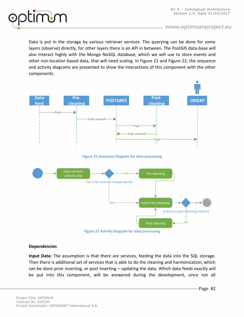
Project Title: OPTIMUM
Contract No. 636160 Project Coordinator: INTRASOFT International S.A.
Page 82
D1.4 – Conceptual Architecture
Version 2.0, Date 31/03/2017
Data is put in the storage by various retriever services. The querying can be done for some
layers (observe) directly, for other layers there is an API in between. The PostGIS data-base will
also interact highly with the Mongo NoSQL database, which we will use to store events and
other non-location based data, that will need scaling. In Figure 21 and Figure 22, the sequence
and activity diagrams are presented to show the interactions of this component with the other
components.
ssData feed
POSTGRESPOSTGRESPOSTGRESPre-
cleaningPOSTGRESPost-
cleaning
Push
Push cleaned
Pull
Push cleaned
ORIENTORIENT
Pull
Figure 21 Sequence Diagram for data processing
Data retriever collects data
Can it be cleaned independently
Pre-cleaning
Insert into database
YES
NO
Is there a post-cleaning method
NO
YESPost-cleaning
Figure 22 Activity Diagram for data processing
Dependencies
Input Data: The assumption is that there are services, feeding the data into the SQL storage.
Then there is additional set of services that is able to do the cleaning and harmonization, which
can be done prior inserting, or post inserting – updating the data. Which data feeds exactly will
be put into this component, will be answered during the development, since not all
Project Title: OPTIMUM
Contract No. 636160 Project Coordinator: INTRASOFT International S.A.
Page 83
D1.4 – Conceptual Architecture
Version 2.0, Date 31/03/2017
components need a big amount of permanent storage. For some components the raw files +
some way to import them into memory will be good enough.
Output Data: This component will produce a permanent storage for a data-feeds that we
decide, we need some window of history. Mostly this will be consumed by orient and higher
layers, but also the cleaning and harmonization tools need a historical window of data at any
point.
Functions: Functions to produce a historical window of data about user locations, user paths,
traffic events, traffic measurements, and other data that need to survive machine restarts.
Assumption: Data retrieval modules for various data feeds are able to push the data in, and
maintain a needed historical window.
Interfaces
This is a service that runs on one or more server, accessible over the closed network. The internal sub-component will be part of the data-infrastructure and can store social media data as well. The external sub-component will orient modules and are able to query and retrieve the data (batch loading for the analytics). External users (organizations) can access some of this data, regulated by the access web-services, which are built around that.
5.1.3 Semantic services Purpose
This component aims at using the Resource Description Framework for conceptual description
or modeling of information Related to static sources (sensors) and to dynamic sources (events).
The result will be a software module as an extension to the database for data enrichment and
alignment.
In the case of traffic-related events (social, sports, cultural and actual traffic events) the idea is
to cross data from this panoply of sources in order to semantically extrapolate cause-
consequence patterns from them, in order to forecast new patterns in the future. For instance,
if, whenever there is a social event occurring, such as a football match or a demonstration,
some roads are affected before, during and after the duration of the event. Hence, the idea is
to get this relation between traffic events and other events.
In the case of sensors, the objective is to semantically annotate sensor metadata in order for
facilitate the application of analytical and statistical methods by sensor characteristics, such as
sensor type, granularity dimensions and measurement types. In this way, comparison and
correlation between sensor data can be achieved taking into account all the characteristics of
the sensors being analyzed.
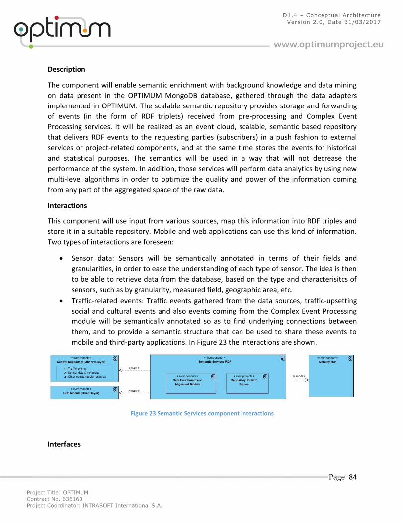
Project Title: OPTIMUM
Contract No. 636160 Project Coordinator: INTRASOFT International S.A.
Page 84
D1.4 – Conceptual Architecture
Version 2.0, Date 31/03/2017
Description
The component will enable semantic enrichment with background knowledge and data mining
on data present in the OPTIMUM MongoDB database, gathered through the data adapters
implemented in OPTIMUM. The scalable semantic repository provides storage and forwarding
of events (in the form of RDF triplets) received from pre-processing and Complex Event
Processing services. It will be realized as an event cloud, scalable, semantic based repository
that delivers RDF events to the requesting parties (subscribers) in a push fashion to external
services or project-related components, and at the same time stores the events for historical
and statistical purposes. The semantics will be used in a way that will not decrease the
performance of the system. In addition, those services will perform data analytics by using new
multi-level algorithms in order to optimize the quality and power of the information coming
from any part of the aggregated space of the raw data.
Interactions
This component will use input from various sources, map this information into RDF triples and
store it in a suitable repository. Mobile and web applications can use this kind of information.
Two types of interactions are foreseen:
Sensor data: Sensors will be semantically annotated in terms of their fields and
granularities, in order to ease the understanding of each type of sensor. The idea is then
to be able to retrieve data from the database, based on the type and characterisitcs of
sensors, such as by granularity, measured field, geographic area, etc.
Traffic-related events: Traffic events gathered from the data sources, traffic-upsetting
social and cultural events and also events coming from the Complex Event Processing
module will be semantically annotated so as to find underlying connections between
them, and to provide a semantic structure that can be used to share these events to
mobile and third-party applications. In Figure 23 the interactions are shown.
Figure 23 Semantic Services component interactions
Interfaces
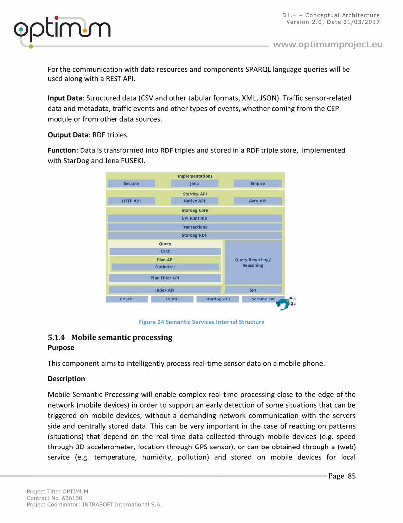
Project Title: OPTIMUM
Contract No. 636160 Project Coordinator: INTRASOFT International S.A.
Page 85
D1.4 – Conceptual Architecture
Version 2.0, Date 31/03/2017
For the communication with data resources and components SPARQL language queries will be used along with a REST API. Input Data: Structured data (CSV and other tabular formats, XML, JSON). Traffic sensor-related
data and metadata, traffic events and other types of events, whether coming from the CEP
module or from other data sources.
Output Data: RDF triples.
Function: Data is transformed into RDF triples and stored in a RDF triple store, implemented
with StarDog and Jena FUSEKI.
Figure 24 Semantic Services Internal Structure
5.1.4 Mobile semantic processing
Purpose
This component aims to intelligently process real-time sensor data on a mobile phone.
Description
Mobile Semantic Processing will enable complex real-time processing close to the edge of the
network (mobile devices) in order to support an early detection of some situations that can be
triggered on mobile devices, without a demanding network communication with the servers
side and centrally stored data. This can be very important in the case of reacting on patterns
(situations) that depend on the real-time data collected through mobile devices (e.g. speed
through 3D accelerometer, location through GPS sensor), or can be obtained through a (web)
service (e.g. temperature, humidity, pollution) and stored on mobile devices for local
Project Title: OPTIMUM
Contract No. 636160 Project Coordinator: INTRASOFT International S.A.
Page 86
D1.4 – Conceptual Architecture
Version 2.0, Date 31/03/2017
processing. The main challenge is the proper definition of the context this local processing will
be done. We will use semantic technologies for supporting interoperability between different
types of sensors and devices, e.g. in the case that two different sensors for tracking activity
should be combined. In addition, the usage of semantics will support collaborative scenarios,
where different actors will cooperate in achieving/optimizing some transportation goals. It
includes the following Internal modules:
o Mobile CEP is an Android implementation of the Lite CEP engine. It is responsible for managing patterns execution. Mobile CEP includes the pattern manager library which enables creation of patterns.
o Self-reporting component is responsible for manually managing the reports by the user. o Sensor management component is responsible for managing sensor connections. o The Dispatcher component is used to dispatch the data to the registered components. o Data push receiver component is responsible for registering push notifications from the
server, receiving them and sending to the dispatcher for further processing. o Local storage of patterns.
Its external modules are:
o Detected pattern/situation of interest o Data to be uploaded to the server
Interactions
Beside the real-time data collected using own sensors (like GPS sensor) this component will
collect data from the local repositories (close to mobile phone, like sensors in the truck,
smartwatch) and receive complex events from Complex Event Processing component. The
results will be sent to the Recommendation service. In addition, it will store input data and
detected patterns to Optimum’s central repository. The interactions are shown in Figure 25.
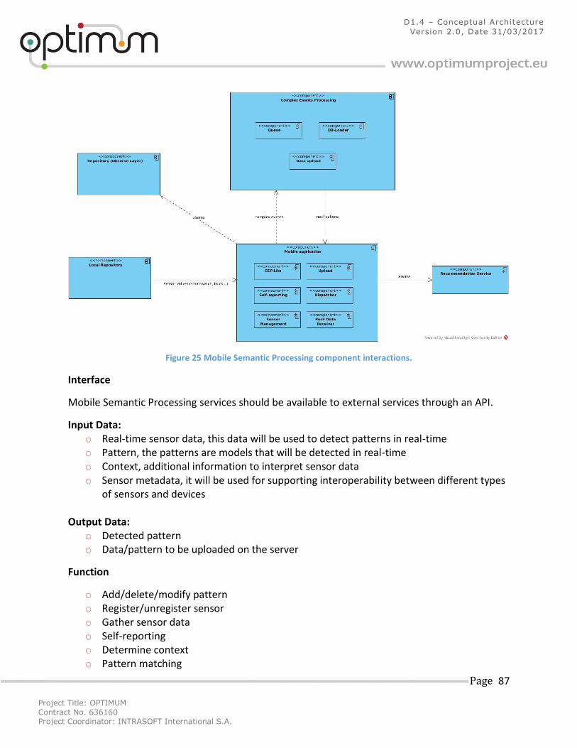
Project Title: OPTIMUM
Contract No. 636160 Project Coordinator: INTRASOFT International S.A.
Page 87
D1.4 – Conceptual Architecture
Version 2.0, Date 31/03/2017
Figure 25 Mobile Semantic Processing component interactions.
Interface
Mobile Semantic Processing services should be available to external services through an API.
Input Data: o Real-time sensor data, this data will be used to detect patterns in real-time o Pattern, the patterns are models that will be detected in real-time o Context, additional information to interpret sensor data o Sensor metadata, it will be used for supporting interoperability between different types
of sensors and devices Output Data:
o Detected pattern o Data/pattern to be uploaded on the server
Function
o Add/delete/modify pattern o Register/unregister sensor o Gather sensor data o Self-reporting o Determine context o Pattern matching
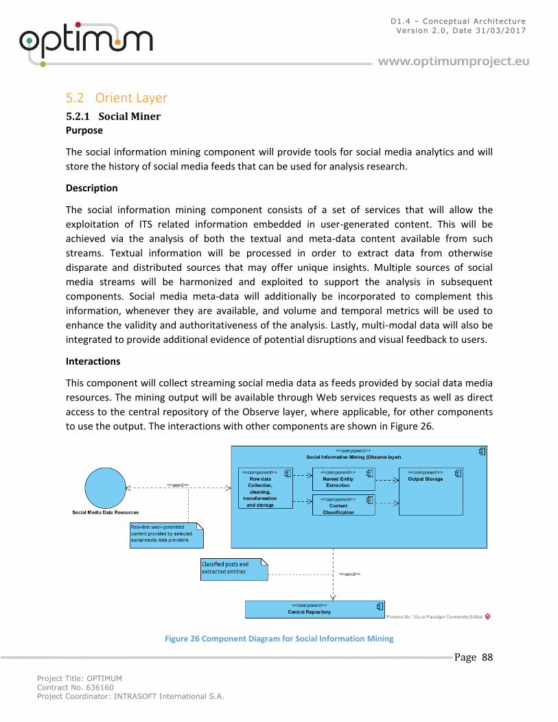
Project Title: OPTIMUM
Contract No. 636160 Project Coordinator: INTRASOFT International S.A.
Page 88
D1.4 – Conceptual Architecture
Version 2.0, Date 31/03/2017
5.2 Orient Layer 5.2.1 Social Miner Purpose
The social information mining component will provide tools for social media analytics and will
store the history of social media feeds that can be used for analysis research.
Description
The social information mining component consists of a set of services that will allow the
exploitation of ITS related information embedded in user-generated content. This will be
achieved via the analysis of both the textual and meta-data content available from such
streams. Textual information will be processed in order to extract data from otherwise
disparate and distributed sources that may offer unique insights. Multiple sources of social
media streams will be harmonized and exploited to support the analysis in subsequent
components. Social media meta-data will additionally be incorporated to complement this
information, whenever they are available, and volume and temporal metrics will be used to
enhance the validity and authoritativeness of the analysis. Lastly, multi-modal data will also be
integrated to provide additional evidence of potential disruptions and visual feedback to users.
Interactions
This component will collect streaming social media data as feeds provided by social data media
resources. The mining output will be available through Web services requests as well as direct
access to the central repository of the Observe layer, where applicable, for other components
to use the output. The interactions with other components are shown in Figure 26.
Figure 26 Component Diagram for Social Information Mining
Project Title: OPTIMUM
Contract No. 636160 Project Coordinator: INTRASOFT International S.A.
Page 89
D1.4 – Conceptual Architecture
Version 2.0, Date 31/03/2017
Dependencies
Input Data: The input data will be real-time social data streams provided by social media data
resources. Relevant data attributes, such as the unstructured textual content of the social
posts, as well as the semi-structured meta-data content, such as user profile, the post geo-
location, and the post timestamp.
Output Data: The output data will be the classification of posts into relevant categories. This
includes sentiment classification of posts. Named entities, such as events and places, will be
extracted from the textual content. In addition, output data will include structured social data,
such as aggregated time-series numbers of posts, and numbers of posting users.
Functions: Functional data adaptors to collect, pre-process, transform, and store social data
streams into a central repository will be implemented. Advanced natural language processing
(NLP) and text mining techniques will be employed to classify as well as extract the named
entities from the transformed streams.
Assumption: This component assumes that considerable and highly temporal volume of user-
generated content is accessible from several social media data providers. These may include:
the public Twitter Streaming API7, GNIP8 for for real time access to unfiltered Twitter content,
Datasift9 for Facebook topic data, access to anonymized Foursquare check-ins10, Factual11 for
venues and places data, Waze API12 for accessing navigation, map view and real-time data,
Google Calendar API13 for personal mobility plan, News Sites, and Blogs.
Interfaces and Sub-components
Social feeds as well as the component outputs will be available through REST Web services, and
also direct access to the database, where applicable.
5.2.2 Online Stream Analytics
Purpose
This platform provides tools for real-time stream analytics (e.g. loop sensors, sensors from
motorhomes, traffic infrastructure, GPS coordinates of vehicles, people, tweets; or more
generally, streams of structured or unstructured data).
7 https://dev.twitter.com/streaming/overview
8 http://support.gnip.com/apis/firehose/overview.html
9 http://datasift.com/
10 https://gnip.com/sources/foursquare/
11 https://www.factual.com/
12 https://www.waze.com/about/dev
13 https://developers.google.com/google-apps/calendar/
Project Title: OPTIMUM
Contract No. 636160 Project Coordinator: INTRASOFT International S.A.
Page 90
D1.4 – Conceptual Architecture
Version 2.0, Date 31/03/2017
Description
The basic tool of this platform is QMiner (JSI, n.d.) (http://qminer.ijs.si/). QMiner is an open-
source data analytics platform for processing large-scale real-time streams containing
structured or unstructured data. It is actively being used and developed by multiple research
and commercial projects solving a numerous number of machine learning and stream analytics
problems. These are ranging from anomaly detection, traffic prediction, recommendation
systems and social sentiment analysis to the energy consumption prediction. It implements a
comprehensive set of techniques for supervised, unsupervised and active learning on streams
of data. It enables easy extraction of rich feature vectors from data streams using the data
importing, normalization, re-sampling, merging and enrichment functionality. It also provides
support for unstructured data (such as text) from feature engineering and indexing to
aggregation and on top of that various machine learning methods.
Interactions
This component is readily available for use in the Optimum project and it already drives two
stream analytics Optimum APIs, described later. The interaction with the component can be
divided onto two parts. One is internal API and scripting interfaces, which is being used to solve
particular problem. The second one is the external API, which depends on, how the developer
of the solution structured and envisioned the system. External API is then accessible to the rest
of the Optimum project and also general public through RESTful API.
Internal interactions
The core of the QMiner platform and its components is written in C++ and then compiled to
support Linux, Windows and OSX platforms. These native and fast methods are then exposed to
the developers as a JavaScript objects, which can be used in the Node.js scripting engine. This
allows us to maintain the speed, and be very flexible and easy to use at the same time. The
developers do not need to know the C++ language or internal structures of the streaming
engine, but only the very common JavaScript scripting language and the specifics of their
problem. The internal API of the QMiner follows similar nomenclature and structure as the very
common Scikit-learn for Python (http://scikit-learn.org/stable/).
The internal API is very well documented on the QMiner web site:
https://rawgit.com/qminer/qminer/master/nodedoc/index.html
Because the API itself is quite big, it does not make sense to include it in this document. It
consists of 55 groups of functions, which range from NN (neural networks), KMeans (K-Means
Project Title: OPTIMUM
Contract No. 636160 Project Coordinator: INTRASOFT International S.A.
Page 91
D1.4 – Conceptual Architecture
Version 2.0, Date 31/03/2017
clustering), RidgeReg (Ridge regression), Tokenizer (text tokenizer), StreamAggregateHistogram,
etc.
External interactions
While internal API serves mostly the developer that is working on an analytics problem he
would like to solve, the developer usually exposes some parts, or the inputs and outputs of his
solution to the external world. Due to node.js, which is a server-side scripting engine, this can
be very easily done in QMiner. These external APIs then server the project, or the world, to
easily get the results, or push in the needed data. How this API looks like it then depends on the
solution and the requirement. When necessary, it’s also possible to arrange more instances of
the platform, where each of them is a replication (for speed – load balancing), or only solves a
prat of the problem. This can be seen in the example architecture on Figure 27 below.
Figure 27: Example of distributed QMiner solution
The OPTIMUM API from the Figure 27 above, can be imagined as only one access point, which
returns the results as soon as the data are pushed , in a streaming fashion. On the image we
only represent it as two layers, to show the data-flow of the architectural solution multiple
QMiner and Database instances.
The solutions using QMiner have interfaces for input data reception, which currently consist of
data from social media feeds, real time streams of traffic information, real-time feeds of
personal GPS data, and historical data already stored in the central database of Optimum
Project Title: OPTIMUM
Contract No. 636160 Project Coordinator: INTRASOFT International S.A.
Page 92
D1.4 – Conceptual Architecture
Version 2.0, Date 31/03/2017
(Observe layer). Its output is then either, received immediately after data is being pushed in, or
upon request through the API at any time later. The results of QMiner solutions will be stored
to the central OPTIMUM repository. Other system components such as Traveler Behavior
Modeling, and Traffic Forecasting Engine, are built using QMiner, while other, like Multimodal
Routing Engine and Mobile/Web applications can make direct use of the output of this
component. These interactions are presented in Figure 28.
Figure 28: QMiner platform in relation of the OODA architecture of OPTIMUM
Interfaces
As mentioned in the External Interactions chapter above, the interfaces are totally customize-
able and depend on the problem and solution.
Input Data:
o Real-time streams
o Data from observe layer
o Tweets
Output Data:
o Stream aggregates
o Predictions
o Classified tweets
Function:
o User path predictions
o Traffic predictions
o Sentiment analysis

Project Title: OPTIMUM
Contract No. 636160 Project Coordinator: INTRASOFT International S.A.
Page 93
D1.4 – Conceptual Architecture
Version 2.0, Date 31/03/2017
Assumptions: Considerable amount of data is assumed to be available.
5.2.3 Travel Behavior Model
Purpose
This component aims to develop and implement behavioral models that will be used for the
population segmentation on various traveler profiles and to provide probabilities for mode
choice.
Description
This component is intended to utilize the dynamics of daily activity decision making process,
motivated by several studies confirming that individuals change their daily activity schedule and
decisions on a day-to-day basis. The component will implement traveler behavioral models
that will consider weights of several factors affecting travelers’ choices. These include
socioeconomic characteristics (e.g. age, gender, income, occupation, nature of disability,
ethnicity, number of children), travel characteristics (usual mode, purpose of trip, delays,
incidents en- route), mode attributes (e.g. travel time, travel cost), attitudes and perceptions,
and constrains (car ownership, awareness of the service provided, need for travelling with
specific mode, time constraints.
Interactions
This component will collect required data from the central repository of the Observe layer and
give its output to the system aware optimization and recommendation and personalization
components. It will also react with the routing engine in order to acquire input for model
application per OD (origin-destination). Finally, it will react with the persuasive techniques in
WP5. In Figure 29 the interactions are shown.
Project Title: OPTIMUM
Contract No. 636160 Project Coordinator: INTRASOFT International S.A.
Page 94
D1.4 – Conceptual Architecture
Version 2.0, Date 31/03/2017
Figure 29 Interactions with the Travel Behavioral Model
Dependencies
Input Data: During the model development phase, the input data will be collected from the
pilot case studies. In the model application phase, it is envisioned that the required information
will be provided by the end users through registration and before using the OPTIMUM services.
For the application of the model the routing engine should be able to provide OD routes for the
considered alternatives, travel time and travel cost.
Output Data: The outputs of the component will consist of both descriptive analytics outputs,
such as population segments based on travelers’ profiles, as well as predictive analytics
outputs, such as the prediction of mode choice for current and future conditions for each
traveler profile.
Functions: The functions include customization of Information based on Travelers’ Profiles,
user classification and mode choice prediction.
Assumption: Availability of the required input data which will be provided by the end users in
the pilot case studies during the development phase and through registration before using the
OPTIMUM services.
Dataneededforthemodeldevelopment
Dataneededforthemodelapplication
EquationTravelBehavioralModel
PopulationSegmentationTravelerProfiles
ModeChoicePrediction
DatacollectedfromRevealedandStatedPreferences(RP&
SP)
Datacollectedfrom1st
Pilot
Databasewithindividualmobilitypatterns
Inputfromroutingengineandtrafficsimulation
model
Project Title: OPTIMUM
Contract No. 636160 Project Coordinator: INTRASOFT International S.A.
Page 95
D1.4 – Conceptual Architecture
Version 2.0, Date 31/03/2017
5.2.4 Traffic Forecasting Engine
Purpose
Traffic Forecasting Engine will provide forecasting models for the short and medium-term
prediction of traffic data like the travel demand time, flow and travel conditions for urban and
inter-urban trips.
Description
This component will contain a set of subcomponents. These are described as follows.
Data collection and preprocessing. A component for the collection and fusion of the necessary
data for the operation of the Traffic Forecasting Engine. These data can include, traffic
measurements, social information, weather data, road network, public transportation data,
incidents. Data can come from historical and real-time information data sources. This
component will also perform any cleaning and transformation on the data e.g. temporal
aggregations, features selection. The data will be ready for consumption for the other
subcomponents of the Forecasting Engine that will perform the analysis.
Simulator. A micro-simulation component for the implementation of real time simulations
when historical data cannot be used to accurately predict traffic levels due to high level of
service variations and uncertainties. The Aimsun14 tool will be used as a simulator engine.
Aimsun is a traffic modelling software that allows you to model various traffic conditions. It
stands out for the exceptionally high speed of its simulations and for fusing travel demand
modelling, static and dynamic traffic assignment with mesoscopic, microscopic and hybrid
simulation. The main purpose of the simulations is to complement forecasting models in areas
of the network with low sensor coverage, as well as, complement the forecasting using the
models listed below. For the purposes of OPTIMUM the Aimsun modelling and simulation tools
has been chosen due to the following reasons:
Intuitive GUI for the development of a network.
Provides APIs for automating modelling tasks (e.g. placement of detectors/sensors on
different sections of the network). Such functionality is important for modelling
efficiency (>2000 sensors for the UK pilot).
Provides APIs for controlling all modelling parameters at each simulation step.
Allows modelling of ITS functionality (e.g lane management, speed limiting, etc.).
Allows modelling of transport events (e.g accidents, lane closures, etc.).
Allows integration of models from other industry/research tools.
14
http://www.aimsun.com
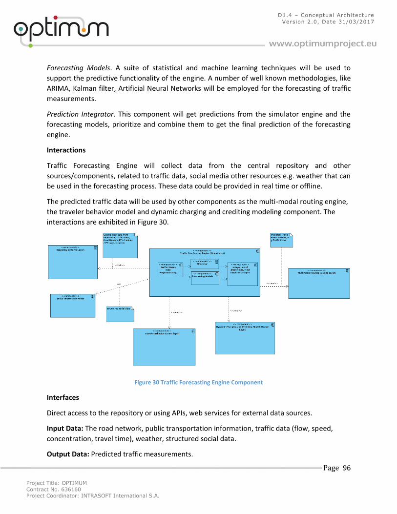
Project Title: OPTIMUM
Contract No. 636160 Project Coordinator: INTRASOFT International S.A.
Page 96
D1.4 – Conceptual Architecture
Version 2.0, Date 31/03/2017
Forecasting Models. A suite of statistical and machine learning techniques will be used to
support the predictive functionality of the engine. A number of well known methodologies, like
ARIMA, Kalman filter, Artificial Neural Networks will be employed for the forecasting of traffic
measurements.
Prediction Integrator. This component will get predictions from the simulator engine and the
forecasting models, prioritize and combine them to get the final prediction of the forecasting
engine.
Interactions
Traffic Forecasting Engine will collect data from the central repository and other
sources/components, related to traffic data, social media other resources e.g. weather that can
be used in the forecasting process. These data could be provided in real time or offline.
The predicted traffic data will be used by other components as the multi-modal routing engine,
the traveler behavior model and dynamic charging and crediting modeling component. The
interactions are exhibited in Figure 30.
Figure 30 Traffic Forecasting Engine Component
Interfaces
Direct access to the repository or using APIs, web services for external data sources.
Input Data: The road network, public transportation information, traffic data (flow, speed,
concentration, travel time), weather, structured social data.
Output Data: Predicted traffic measurements.
Project Title: OPTIMUM
Contract No. 636160 Project Coordinator: INTRASOFT International S.A.
Page 97
D1.4 – Conceptual Architecture
Version 2.0, Date 31/03/2017
Function: Prediction of traffic measurements and traffic simulations.
5.2.5 Goal-driven Complex Event Processing
Purpose
This component aims to support dynamic definition and detection of complex events and
reasoning over events.
Description
Goal-driven Complex Event Processing component has the role of dynamic definition and
detection of complex events and reasoning over events, supplied by Event Storage. Complex
Event Pattern can be defined dynamically or produced by anticipatory services (predictions),
whereas a separate feedback loop will ensure that the patterns will be continuously improved.
This research will extend the open source engine ESPER in the direction of extending it to
enable dynamic (on-the-fly) deployment of new patterns and their monitoring as well as to deal
with semantics. In addition, this component will provide a methodology for the structured,
business goal-driven identification of relevant situations of interest and will leverage detection
of anomalies in real-time providing the basis for proactive actions. It includes the following
internal modules:
o Data upload o Pattern matching o Pattern quality assessment
and external modules:
o Detected pattern/situation of interest o Feedback to mobile phone
Interactions
There are several types of interaction with other components.
Receiving data:
The (real-time) data will be received from the Repository.
The (future) forecasted data will be received from Traffic Forecasting component.
The complex events will be received from Mobile application
Static data (models/information) will be received from Routing Engine Service.
Delivering results:
The notifications about executed patterns will be sent to Mobile application, just to
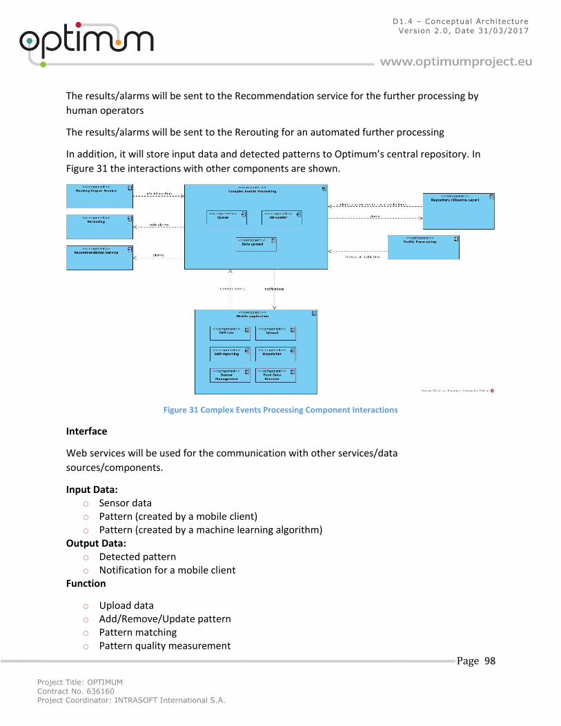
Project Title: OPTIMUM
Contract No. 636160 Project Coordinator: INTRASOFT International S.A.
Page 98
D1.4 – Conceptual Architecture
Version 2.0, Date 31/03/2017
The results/alarms will be sent to the Recommendation service for the further processing by
human operators
The results/alarms will be sent to the Rerouting for an automated further processing
In addition, it will store input data and detected patterns to Optimum’s central repository. In
Figure 31 the interactions with other components are shown.
Figure 31 Complex Events Processing Component Interactions
Interface
Web services will be used for the communication with other services/data
sources/components.
Input Data: o Sensor data o Pattern (created by a mobile client) o Pattern (created by a machine learning algorithm)
Output Data: o Detected pattern o Notification for a mobile client
Function
o Upload data o Add/Remove/Update pattern o Pattern matching o Pattern quality measurement
Project Title: OPTIMUM
Contract No. 636160 Project Coordinator: INTRASOFT International S.A.
Page 99
D1.4 – Conceptual Architecture
Version 2.0, Date 31/03/2017
o Goal-driven pattern refinement o Inform mobile client
5.3 Decide Layer 5.3.1 Multi-modal Routing Engine Purpose
The aim of this component is to provide multimodal routes.
Description
To realize the requested functionality this component will provide a routing engine capable of
returning multimodal routes from a specified origin to a specified destination.
In contrast to classical routing engines, this one will be built on the system aware optimization
model such that routes provided are “system-friendly”, i.e. instead of ego-centric routes
optimizing only individual objectives they will provide routes where social impacts on other
traffic system users will be minimized. It is envisaged that the optimization of the routes for the
benefit of the entire system will be based on criteria that limit the extra cost to individuals,
using thresholds identified through an optimization strategy (e.g. additional route length will be
limited to 10% of the individual optimal). In addition, the users will be informed about the
existence of such routes and the long-term benefits that may induce to their travelling. Further
details regarding the system aware optimization methodology can be found in section 4.1.2 of
deliverable 4.4.
Interactions
This component will receive data from the central repository (Observe layer), forecasted traffic
data from Forecasting Engine, predicted multi modal routes from traveler behavior component.
The output of this component can be used by the pro-act layer Persuasive strategies,
Recommendation and from the mobile/web applications at the user/presentation layer. In
Figure 32 below, the interactions with the other components are shown.
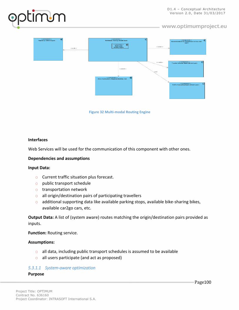
Project Title: OPTIMUM
Contract No. 636160 Project Coordinator: INTRASOFT International S.A.
Page 100
D1.4 – Conceptual Architecture
Version 2.0, Date 31/03/2017
Figure 32 Multi-modal Routing Engine
Interfaces
Web Services will be used for the communication of this component with other ones.
Dependencies and assumptions
Input Data:
o Current traffic situation plus forecast.
o public transport schedule
o transportation network
o all origin/destination pairs of participating travellers
o additional supporting data like available parking stops, available bike-sharing bikes,
available car2go cars, etc.
Output Data: A list of (system aware) routes matching the origin/destination pairs provided as
inputs.
Function: Routing service.
Assumptions:
o all data, including public transport schedules is assumed to be available
o all users participate (and act as proposed)
5.3.1.1 System-aware optimization
Purpose
Project Title: OPTIMUM
Contract No. 636160 Project Coordinator: INTRASOFT International S.A.
Page 101
D1.4 – Conceptual Architecture
Version 2.0, Date 31/03/2017
The main objective of this sub-component of the multi-modal routing engine is to provide the
theoretical and analytical background for incorporating system aware decisions in the
OPTIMUM system.
Description
The aim of this sub-component is to model system aware optimization. While a general concept
will be proposed, the instantiation of this general concept will be provided for routing. System
aware decisions have to integrate a lot of different opinions and constraints. Therefore, it is
necessary to find a model representing “the system” itself, the constraints, and the
requirements stated within the system. In order to deliver not only a general text document, a
(full) example will be provided for the system aware routing use case. The implemented model
will conduct research on strategies towards system optimal solutions but providing socially
acceptable propositions. This model will enhance state-of-the-art in transportation modelling
and will provide the basis towards next generation real-time multimodal routing and navigation
algorithms.
5.3.2 Dynamic Charging and Crediting Model
Purpose
This component aims to develop and implement an econometric model for dynamic charging.
Description
This component will develop an econometric model to identify the price elasticity of truck
operators and provide a tool for dynamic charging to the road operators. Dynamic
charging/crediting can be achieved with a variety of systems and technologies, thus during
development, the best possible solution/combination will be promoted.
Interactions
This component will have interactions with the components in the OBSERVE layer. In particular,
the Road Operator database (containing travel times, routes, toll prices, etc.), operators and
drivers’ surveys conducted in the pilot case. In Figure 33 below, the interactions with the other
components are demonstrated.
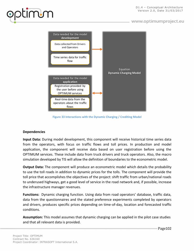
Project Title: OPTIMUM
Contract No. 636160 Project Coordinator: INTRASOFT International S.A.
Page 102
D1.4 – Conceptual Architecture
Version 2.0, Date 31/03/2017
Figure 33 Interactions with the Dynamic Charging / Crediting Model
Dependencies
Input Data: During model development, this component will receive historical time series data
from the operators, with focus on traffic flows and toll prices. In production and model
application, the component will receive data based on user registration before using the
OPTIMUM services. These include data from truck drivers and truck operators. Also, the macro
simulation developed by TIS will allow the definition of boundaries to the econometric model.
Output Data: The component will produce an econometric model which details the probability
to use the toll roads in addition to dynamic prices for the tolls. The component will provide the
toll price that accomplishes the objectives of the project: shift traffic from urban/national roads
to underused highways, get a good level of service in the road network and, if possible, increase
the infrastructure manager revenues.
Functions: Dynamic charging function. Using data from road operators’ database, traffic data,
data from the questionnaires and the stated preference experiments completed by operators
and drivers, produces specific prices depending on time-of-day, location and forecasted traffic
conditions.
Assumption: This model assumes that dynamic charging can be applied in the pilot case studies
and that all relevant data is provided.
Dataneededforthemodeldevelopment
Dataneededforthemodelapplication
EquationDynamicChargingModel
DatacollectedfromDriversandOperators
Timeseriesdatafortrafficflow
RegistrationprovidedbytheuserbeforeusingOPTIMUMservices
Real-timedatafromtheoperatorsaboutthetraffic
flows
Project Title: OPTIMUM
Contract No. 636160 Project Coordinator: INTRASOFT International S.A.
Page 103
D1.4 – Conceptual Architecture
Version 2.0, Date 31/03/2017
5.4 (Pro-) Act Layer 5.4.1 Recommendation and Personalization Services Purpose
The Recommendation & Personalization Services will filter and select appropriate information
to be displayed to the user taking into account the user profile as well as available context. The
recommendation purpose may range from the provision of personalized persuasive messages
and explanations up to the recommendation of routes along with the corresponding
transportation modes, while it may be done for different trip phases, i.e. pre-, on- and post-
trip, depending on the requirements of the use cases and the information that will be available
as input.
Description
The component will employ a combination of recommendation techniques and decision theory
methods while considering the persuasive strategies and user profile. Pre-trip information and
recommendations will include appropriate transportation modes and travel plans and will
consider all available multimodal choices. On-trip information and recommendations will
provide proactive feedback on potential incidents and suggestions for alternative routes. Post-
trip information will include suggestions to refine trips
Interactions
The interactions between the recommendation and personalization services and the other
component are demonstrated in Figure 34 and summarized as below:
Direct provision of possible routes, along with their characteristics by the Decide phase. The
Recommendation & Personalization Service could then filter these routes if such a
requirement arises from the use cases.
Direct provision of relevant context information by the Observe phase components.
Direct provision of triggers to provide push recommendations to the user when the current
situation seems appropriate, without explicit user request for information discovery, by the
components of the Orient phase (CEP).
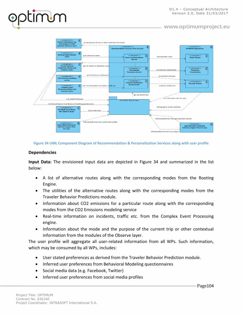
Project Title: OPTIMUM
Contract No. 636160 Project Coordinator: INTRASOFT International S.A.
Page 104
D1.4 – Conceptual Architecture
Version 2.0, Date 31/03/2017
Figure 34 UML Component Diagram of Recommendation & Personalization Services along with user profile
Dependencies
Input Data: The envisioned input data are depicted in Figure 34 and summarized in the list
below:
A list of alternative routes along with the corresponding modes from the Rooting
Engine.
The utilities of the alternative routes along with the corresponding modes from the
Traveler Behavior Predictions module.
Information about CO2 emissions for a particular route along with the corresponding
modes from the CO2 Emissions modeling service
Real-time information on incidents, traffic etc. from the Complex Event Processing
engine.
Information about the mode and the purpose of the current trip or other contextual
information from the modules of the Observe layer.
The user profile will aggregate all user-related information from all WPs. Such information,
which may be consumed by all WPs, includes:
User stated preferences as derived from the Traveler Behavior Prediction module.
Inferred user preferences from Behavioral Modeling questionnaires
Social media data (e.g. Facebook, Twitter)
Inferred user preferences from social media profiles
Project Title: OPTIMUM
Contract No. 636160 Project Coordinator: INTRASOFT International S.A.
Page 105
D1.4 – Conceptual Architecture
Version 2.0, Date 31/03/2017
User demographic and other information as given in the OPTIMUM application (e.g.
through registration)
User interactions with the OPTIMUM applications
Inferred user preferences through the analysis of user interaction with the OPTIMUM
applications
Inferred user preferences through the analysis of the user trips
Output Data: The envisioned output data are depicted in Figure 34 and summarized in the list
below:
A personalized list of recommended routes to be displayed within the OPTIMUM
application
Personalized persuasive visualizations to be displayed within the OPTIMUM application
Personalized messages to be displayed within the OPTIMUM application
Proactive notifications to be displayed within the OPTIMUM application
Functions: Services/functions required for the operation of the component are:
Identification of mode used by the traveler
Detection of trip purpose
Multimodal route planning
Context provision service
Complex event processing service
Emission modeling service
Assumption: There are application level modules of mobile and web applications to which the
recommender provides input, such as journey planner, persuasion visualizations, message
displays etc.
Interfaces and Sub-components:
As implied by its name, the Recommendation & Personalization Services will be delivered as a
set of software services (potentially REST services).
5.5 User and system interfaces 5.5.1 External Data Access Web Services Purpose
The purpose of this component is to provide some control over the data-access – especially of
otherwise unsecured components, such as SQL and NoSql databases, as well as QMiner.
Description
This component adds an additional logic and layer on top of the data that are available inside
OPTIMUM. The component will enable us to have some control over which data and to whom
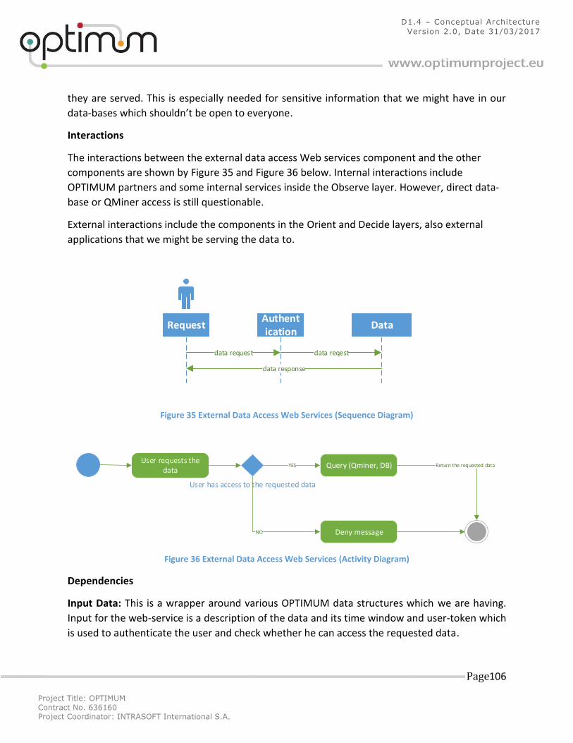
Project Title: OPTIMUM
Contract No. 636160 Project Coordinator: INTRASOFT International S.A.
Page 106
D1.4 – Conceptual Architecture
Version 2.0, Date 31/03/2017
they are served. This is especially needed for sensitive information that we might have in our
data-bases which shouldn’t be open to everyone.
Interactions
The interactions between the external data access Web services component and the other
components are shown by Figure 35 and Figure 36 below. Internal interactions include
OPTIMUM partners and some internal services inside the Observe layer. However, direct data-
base or QMiner access is still questionable.
External interactions include the components in the Orient and Decide layers, also external
applications that we might be serving the data to.
ssAuthentication
POSTGRESData
data reqest
ORIENTRequest
data response
data request
Figure 35 External Data Access Web Services (Sequence Diagram)
User requests the data
User has access to the requested data
Query (Qminer, DB)
Deny message
YES
NO
Return the requested data
Figure 36 External Data Access Web Services (Activity Diagram)
Dependencies
Input Data: This is a wrapper around various OPTIMUM data structures which we are having.
Input for the web-service is a description of the data and its time window and user-token which
is used to authenticate the user and check whether he can access the requested data.
Project Title: OPTIMUM
Contract No. 636160 Project Coordinator: INTRASOFT International S.A.
Page 107
D1.4 – Conceptual Architecture
Version 2.0, Date 31/03/2017
Output Data: This component will produce the requested data feed for the requested time
window.
Functions:
This component will provide function for the retrieval of the various data from OPTIMUM and
authentication of the requesters.
Assumption: This component assumes that there is a permanent data-storage for the
requested data – and the user has the rights to access
Interfaces:
This component will provide data access interfaces through a Rest Web Services API.
Implementation
Considering all that is written above, data sources provided by Optimum will have an additional
security layer. Each data source (or cluster of data sources) will have an administrator (or more
of them) that will have access to admin console. Through admin console it will be possible to
grant (provide tokens) or deny access to users for a particular data source.
We are already developing a web service that will expose data provided by LPP to the outside
world. This service will enable users (Optimum being the first one) to obtain data through
RESTful API. However, as described above, there will be additional layer for security and control
reasons. Below, this layer is described as it can be considered as a prototype for other
Optimum’s data sources security layer. Given that this version is a prototype, and it might still
change during development.
As already explained above, users will only be granted access to the data by an administrator.
Administrator can do that via admin interface. To access it, login is required (Figure 37).
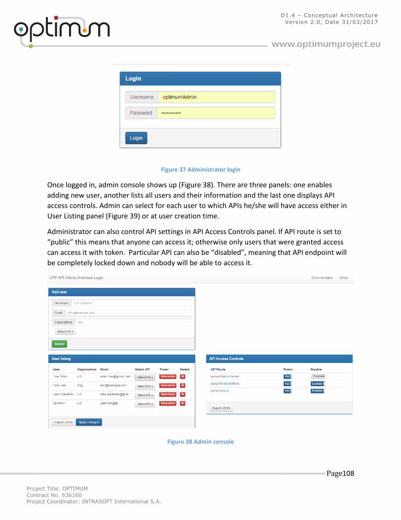
Project Title: OPTIMUM
Contract No. 636160 Project Coordinator: INTRASOFT International S.A.
Page 108
D1.4 – Conceptual Architecture
Version 2.0, Date 31/03/2017
Figure 37 Administrator login
Once logged in, admin console shows up (Figure 38). There are three panels: one enables
adding new user, another lists all users and their information and the last one displays API
access controls. Admin can select for each user to which APIs he/she will have access either in
User Listing panel (Figure 39) or at user creation time.
Administrator can also control API settings in API Access Controls panel. If API route is set to
“public” this means that anyone can access it; otherwise only users that were granted access
can access it with token. Particular API can also be “disabled”, meaning that API endpoint will
be completely locked down and nobody will be able to access it.
Figure 38 Admin console
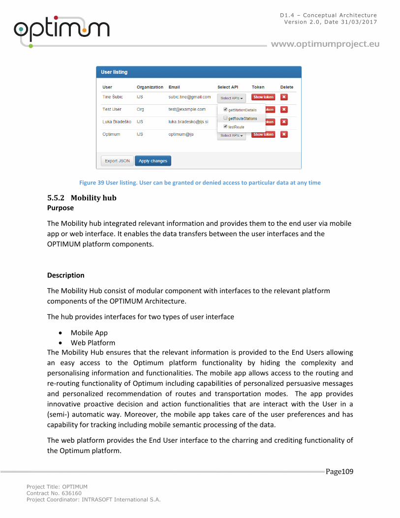
Project Title: OPTIMUM
Contract No. 636160 Project Coordinator: INTRASOFT International S.A.
Page 109
D1.4 – Conceptual Architecture
Version 2.0, Date 31/03/2017
Figure 39 User listing. User can be granted or denied access to particular data at any time
5.5.2 Mobility hub Purpose
The Mobility hub integrated relevant information and provides them to the end user via mobile
app or web interface. It enables the data transfers between the user interfaces and the
OPTIMUM platform components.
Description
The Mobility Hub consist of modular component with interfaces to the relevant platform
components of the OPTIMUM Architecture.
The hub provides interfaces for two types of user interface
Mobile App
Web Platform The Mobility Hub ensures that the relevant information is provided to the End Users allowing
an easy access to the Optimum platform functionality by hiding the complexity and
personalising information and functionalities. The mobile app allows access to the routing and
re-routing functionality of Optimum including capabilities of personalized persuasive messages
and personalized recommendation of routes and transportation modes. The app provides
innovative proactive decision and action functionalities that are interact with the User in a
(semi-) automatic way. Moreover, the mobile app takes care of the user preferences and has
capability for tracking including mobile semantic processing of the data.
The web platform provides the End User interface to the charring and crediting functionality of
the Optimum platform.
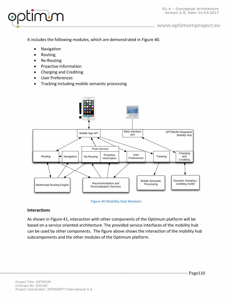
Project Title: OPTIMUM
Contract No. 636160 Project Coordinator: INTRASOFT International S.A.
Page 110
D1.4 – Conceptual Architecture
Version 2.0, Date 31/03/2017
It includes the following modules, which are demonstrated in Figure 40.
Navigation
Routing
Re-Routing
Proactive Information
Charging and Crediting
User Preferences
Tracking including mobile semantic processing
Figure 40 Mobility Hub Modules
Interactions
As shown in Figure 41, interaction with other components of the Optimum platform will be
based on a service oriented architecture. The provided service interfaces of the mobility hub
can be used by other components. The figure above shows the interaction of the mobility hub
subcomponents and the other modules of the Optimum platform.
Dynamic charging /crediting model
Mobile Semantic ProcessingRecommendation and
Personalisation Services Mulitmodal Routing Engine
OPTIMUM Integrated Mobility Hub
Mobile App APIWeb Interface
API
RoutingCharging
and Crediting
User Preferences
Tracking
Push-Service
Re-RoutingProactive
InformationNavigation
!
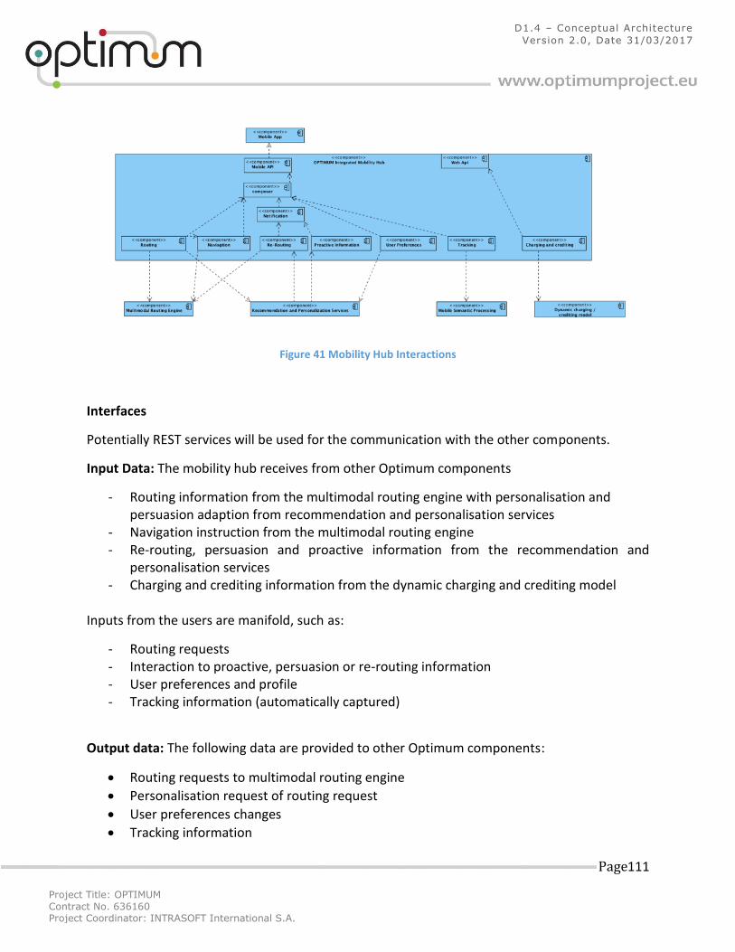
Project Title: OPTIMUM
Contract No. 636160 Project Coordinator: INTRASOFT International S.A.
Page 111
D1.4 – Conceptual Architecture
Version 2.0, Date 31/03/2017
Figure 41 Mobility Hub Interactions
Interfaces
Potentially REST services will be used for the communication with the other components.
Input Data: The mobility hub receives from other Optimum components
- Routing information from the multimodal routing engine with personalisation and persuasion adaption from recommendation and personalisation services
- Navigation instruction from the multimodal routing engine - Re-routing, persuasion and proactive information from the recommendation and
personalisation services - Charging and crediting information from the dynamic charging and crediting model
Inputs from the users are manifold, such as:
- Routing requests - Interaction to proactive, persuasion or re-routing information - User preferences and profile - Tracking information (automatically captured)
Output data: The following data are provided to other Optimum components:
Routing requests to multimodal routing engine
Personalisation request of routing request
User preferences changes
Tracking information
Project Title: OPTIMUM
Contract No. 636160 Project Coordinator: INTRASOFT International S.A.
Page 112
D1.4 – Conceptual Architecture
Version 2.0, Date 31/03/2017
The output data for the user are:
Routing information and routing alternatives
Navigation instructions
Notification including re-routing, persuasion and proactive information
Charging information
Project Title: OPTIMUM
Contract No. 636160 Project Coordinator: INTRASOFT International S.A.
Page 113
D1.4 – Conceptual Architecture
Version 2.0, Date 31/03/2017
6 Data security 6.1 Introduction A model that is designed to guide policies for information security is CIA triad (confidentiality,
integrity and availability). In this context, confidentiality is a set of rules that limits access to
information, integrity is the assurance that the information is trustworthy and accurate, and
availability is a guarantee of reliable access to the information by authorized people.
Most applications need to know the identity of a user. Knowing a user's identity allows an app
to provide a customized experience and grant them permissions to access their data. The
process of confirming a user identity is called authentication. If the credentials, provided by
user, are correct the process is completed and the user is granted authorization for access.
Authorization is actually the function of specifying access rights (permissions) to resources.
Access control in computer systems and networks rely on access policies. The access control
process can be divided into the following two phases:
1) Policy definition phase where access is authorized, and
2) Policy enforcement phase where access requests are approved or disapproved.
Authorization is thus the function of the policy definition phase which precedes the policy
enforcement phase where access requests are approved or disapproved based on the
previously defined authorizations. Assuming that someone has logged in to a computer
operating system or application, the system or application may want to identify what resources
the user can be given during this session. Thus, authorization is sometimes seen as both the
preliminary setting up of permissions by a system administrator and the actual checking of the
permission values that have been set up when a user is getting access. An open protocol that
allows secure authorization in a simple and standard method from web, mobile and desktop
applications is OAuth15 (2.0 is most recent version).
The OAuth 2.0 authorization framework enables a third-party application to obtain limited
access to an HTTP service, either on behalf of a resource owner by organizing an approval
interaction between the resource owner and the HTTP service, or by allowing the third-party
application to obtain access on its own behalf. OAuth 2.0 focuses on client developer simplicity
while providing specific authorization flows for web applications, desktop applications, mobile
phones, and living room devices.
Before the final concept is explained we have to consider the basic system elements, which
OAuth defines:
15
http://oauth.net/2/
Project Title: OPTIMUM
Contract No. 636160 Project Coordinator: INTRASOFT International S.A.
Page 114
D1.4 – Conceptual Architecture
Version 2.0, Date 31/03/2017
Resource owner - an entity capable of granting access to a protected resource. When the resource owner is a person, it is referred to as an end-user.
Resource server - the server hosting the protected resources, capable of accepting and responding to protected resource requests using access tokens.
Client - An application making protected resource requests on behalf of the resource owner and with its authorization. The term "client" does not imply any particular implementation characteristics (e.g., whether the application executes on a server, a desktop, or other devices).
Authorization server - The server issuing access tokens to the client after successfully authenticating the resource owner and obtaining authorization.
6.2 Proposal First of all, it must be underlined that communication among components must be established
using HTTPS secure protocol. The data are encrypted using the certificates (issued by certificate
authority, e.g. VeriSign16, Global Sign17, SSL.com18, etc.) which is placed on each server (or proxy
server depending on system architecture) that communicate with the clients. Therefore, the
information can be sent in a plaintext form, and https protocol takes care about the
confidentiality and integrity of the data.
The data flow that is shown in Figure 42, which consists of three stages:
1. Token obtaining – Users authenticate themselves through the client using login credentials (e.g. username and password or smart cards). As a result of authentication process, the clients obtain an access token;
2. Requests sending – The client sends the request in order to get specific data from the resource servers. Each request is authorized with the access token which was obtained during the preceding stage;
3. Token validation – When the request arrives on the resource server, it must be verified before any further action done. If the access token is valid, the server processes the data and sends response to the client.
16
https://www.verisign.com 17
https://www.globalsign.com 18
https://www.ssl.com
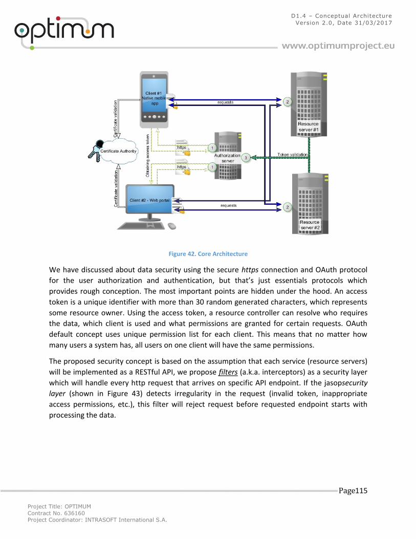
Project Title: OPTIMUM
Contract No. 636160 Project Coordinator: INTRASOFT International S.A.
Page 115
D1.4 – Conceptual Architecture
Version 2.0, Date 31/03/2017
Figure 42. Core Architecture
We have discussed about data security using the secure https connection and OAuth protocol
for the user authorization and authentication, but that’s just essentials protocols which
provides rough conception. The most important points are hidden under the hood. An access
token is a unique identifier with more than 30 random generated characters, which represents
some resource owner. Using the access token, a resource controller can resolve who requires
the data, which client is used and what permissions are granted for certain requests. OAuth
default concept uses unique permission list for each client. This means that no matter how
many users a system has, all users on one client will have the same permissions.
The proposed security concept is based on the assumption that each service (resource servers)
will be implemented as a RESTful API, we propose filters (a.k.a. interceptors) as a security layer
which will handle every http request that arrives on specific API endpoint. If the jasopsecurity
layer (shown in Figure 43) detects irregularity in the request (invalid token, inappropriate
access permissions, etc.), this filter will reject request before requested endpoint starts with
processing the data.
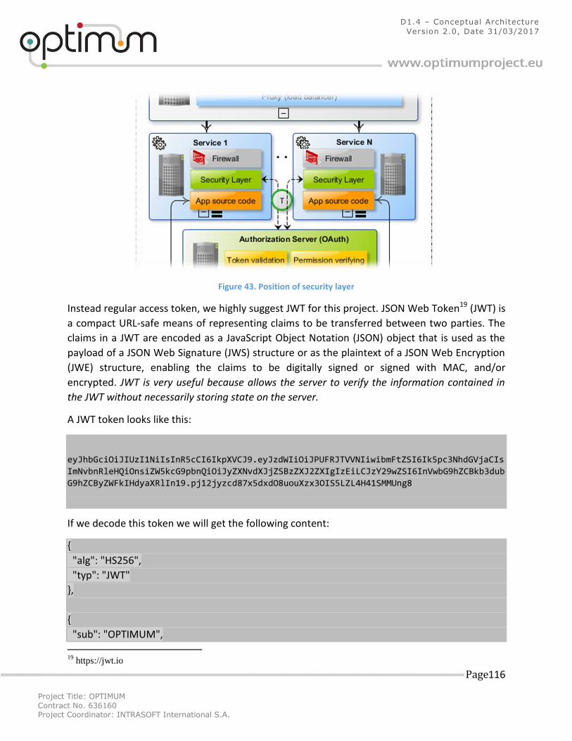
Project Title: OPTIMUM
Contract No. 636160 Project Coordinator: INTRASOFT International S.A.
Page 116
D1.4 – Conceptual Architecture
Version 2.0, Date 31/03/2017
Figure 43. Position of security layer
Instead regular access token, we highly suggest JWT for this project. JSON Web Token19 (JWT) is
a compact URL-safe means of representing claims to be transferred between two parties. The
claims in a JWT are encoded as a JavaScript Object Notation (JSON) object that is used as the
payload of a JSON Web Signature (JWS) structure or as the plaintext of a JSON Web Encryption
(JWE) structure, enabling the claims to be digitally signed or signed with MAC, and/or
encrypted. JWT is very useful because allows the server to verify the information contained in
the JWT without necessarily storing state on the server.
A JWT token looks like this:
eyJhbGciOiJIUzI1NiIsInR5cCI6IkpXVCJ9.eyJzdWIiOiJPUFRJTVVNIiwibmFtZSI6Ik5pc3NhdGVjaCIs
ImNvbnRleHQiOnsiZW5kcG9pbnQiOiJyZXNvdXJjZSBzZXJ2ZXIgIzEiLCJzY29wZSI6InVwbG9hZCBkb3dub
G9hZCByZWFkIHdyaXRlIn19.pj12jyzcd87x5dxdO8uouXzx3OIS5LZL4H41SMMUng8
If we decode this token we will get the following content:
{
"alg": "HS256",
"typ": "JWT"
},
{
"sub": "OPTIMUM",
19
https://jwt.io
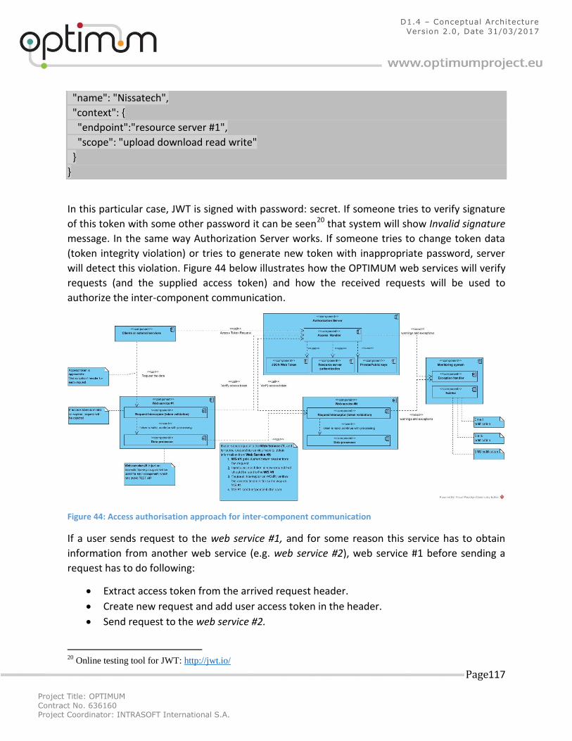
Project Title: OPTIMUM
Contract No. 636160 Project Coordinator: INTRASOFT International S.A.
Page 117
D1.4 – Conceptual Architecture
Version 2.0, Date 31/03/2017
"name": "Nissatech",
"context": {
"endpoint":"resource server #1",
"scope": "upload download read write"
}
}
In this particular case, JWT is signed with password: secret. If someone tries to verify signature
of this token with some other password it can be seen20 that system will show Invalid signature
message. In the same way Authorization Server works. If someone tries to change token data
(token integrity violation) or tries to generate new token with inappropriate password, server
will detect this violation. Figure 44 below illustrates how the OPTIMUM web services will verify
requests (and the supplied access token) and how the received requests will be used to
authorize the inter-component communication.
Figure 44: Access authorisation approach for inter-component communication
If a user sends request to the web service #1, and for some reason this service has to obtain
information from another web service (e.g. web service #2), web service #1 before sending a
request has to do following:
Extract access token from the arrived request header.
Create new request and add user access token in the header.
Send request to the web service #2.
20
Online testing tool for JWT: http://jwt.io/

Project Title: OPTIMUM
Contract No. 636160 Project Coordinator: INTRASOFT International S.A.
Page 118
D1.4 – Conceptual Architecture
Version 2.0, Date 31/03/2017
The request interceptor on the web service #2 will verify if the access token has permission to
access to this service, and if the request is authorized with a valid token, a response will be sent
to the web service #1. The described process allows to authorize inter-component reliable
communication without complex implementation of access policy.
The monitoring system, which is also presented in Figure 44, is composed of the
Exception/Error handler and the Notifier subcomponents. If the Access handler (Authorization
Server) or Request Interceptor (Web Services) detect something unusual, these subcomponents
will send details about the detected problem to the Exception handler. The exception handler
can be implemented as a centralized log manager. For instance, Gray Log21 provides powerful
query language to search through terabytes of log data to discover and analyze important
information, problems or potential attacks. If an attack is detected, details will be stored for
further analysis, and depending on the configuration of the Notifier subcomponent the system
administrator will be notified (in real-time). If the notifications about unusual activities in the
system arrive to the system administrator in real-time, 50% of potential attacks on the system
can be prevented.
6.3 System architecture proposal Most web applications are based on the typical client-server (two-tier) architecture, where
direct communication takes place between client and server with no intermediate handlers.
Because of tight coupling, 2-tiered applications run faster and allow for easier maintenance and
modifications. The multi-tier architecture, on the other hand, provides a model by which
developers can create flexible and reusable applications. Segregating an application into a
tiered system can be extended with various number of a specific layers, still with no structural
changes in the application itself. The most widespread use of a multi-tier architecture is the
three-tier architecture, which allows any one of the three tiers to be upgraded or replaced
independently. A three-tier architecture is typically composed of a presentation tier, a domain
logic and a data storage tier (Figure 45).
21
https://www.graylog.org/
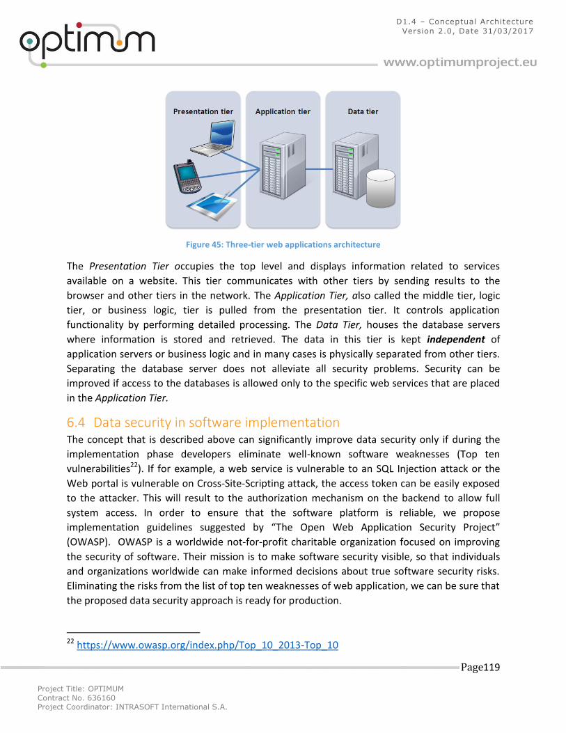
Project Title: OPTIMUM
Contract No. 636160 Project Coordinator: INTRASOFT International S.A.
Page 119
D1.4 – Conceptual Architecture
Version 2.0, Date 31/03/2017
Figure 45: Three-tier web applications architecture
The Presentation Tier occupies the top level and displays information related to services
available on a website. This tier communicates with other tiers by sending results to the
browser and other tiers in the network. The Application Tier, also called the middle tier, logic
tier, or business logic, tier is pulled from the presentation tier. It controls application
functionality by performing detailed processing. The Data Tier, houses the database servers
where information is stored and retrieved. The data in this tier is kept independent of
application servers or business logic and in many cases is physically separated from other tiers.
Separating the database server does not alleviate all security problems. Security can be
improved if access to the databases is allowed only to the specific web services that are placed
in the Application Tier.
6.4 Data security in software implementation The concept that is described above can significantly improve data security only if during the
implementation phase developers eliminate well-known software weaknesses (Top ten
vulnerabilities22). If for example, a web service is vulnerable to an SQL Injection attack or the
Web portal is vulnerable on Cross-Site-Scripting attack, the access token can be easily exposed
to the attacker. This will result to the authorization mechanism on the backend to allow full
system access. In order to ensure that the software platform is reliable, we propose
implementation guidelines suggested by “The Open Web Application Security Project”
(OWASP). OWASP is a worldwide not-for-profit charitable organization focused on improving
the security of software. Their mission is to make software security visible, so that individuals
and organizations worldwide can make informed decisions about true software security risks.
Eliminating the risks from the list of top ten weaknesses of web application, we can be sure that
the proposed data security approach is ready for production.
22 https://www.owasp.org/index.php/Top_10_2013-Top_10
Project Title: OPTIMUM
Contract No. 636160 Project Coordinator: INTRASOFT International S.A.
Page 120
D1.4 – Conceptual Architecture
Version 2.0, Date 31/03/2017
7 Conceptual Architecture Validation The developed conceptual architecture has been validated against the process flows defined in
each of the use cases developed as part of Task 1.3. The purpose of this activity is to ensure
that each process/action of the use cases can be performed by one, or more of the platform’s
components. As it is depicted in Figure 1, the approach followed for the definition of the
conceptual architecture was a mixture of top-down and bottom-up approaches. The
processes/actions used for the validation of the conceptual architecture were derived from the
user requirements, which were in turn used for the definition of the use cases (top-down).
Concurrently, the functionality of the different components was initially defined using the
findings from the state-of-the-art review and was adjusted to meet any requirements that were
not originally taken into consideration (bottom-up). It is envisaged that additional
improvements for the functionality of the platform will be identified throughout the pilots and,
based on their importance, a number of such improvements will be implemented as part of the
second round of development of the individual components.
7.1 Proactive improvement of transport systems quality and efficiency Table 7 lists the processes identified in the use cases for the Birmingham, Ljubljana and Vienna
pilots, as well as their mapping with the relevant components of the OPTIMUM platform.
Table 7: [Pilot 1] Use case processes - System components mapping
Use Case
Actor Process / Action System Component(s)
Use
r R
egi
stra
tio
n
User User downloads the OPTIMUM Android app [Mobility Hub (Mobile Application)]
User User launches the app and is requested to register using a valid email address
[Mobility Hub (Mobile Application)]
OPTIMUM System requests access to data on social profiles
[Mobility Hub (Mobile Application)]
OPTIMUM System stores user data to the OPTIMUM database
[Mobility Hub], [Data Collection, Cleaning and Fusion], [Repository-MongoDB]
De
fin
e
Trip
P
refe
ren
ces
Pro
file
User User logins to the mobile app for first time use.
[Mobility Hub (Mobile Application)]
OPTIMUM System displays questionnaire on mobile app. [Mobility Hub (Mobile Application)], [Travel Behavior Model], [Recommendation & Personalization Services]
User User completes questionnaire using the mobile app.
[Mobility Hub (Mobile Application)]
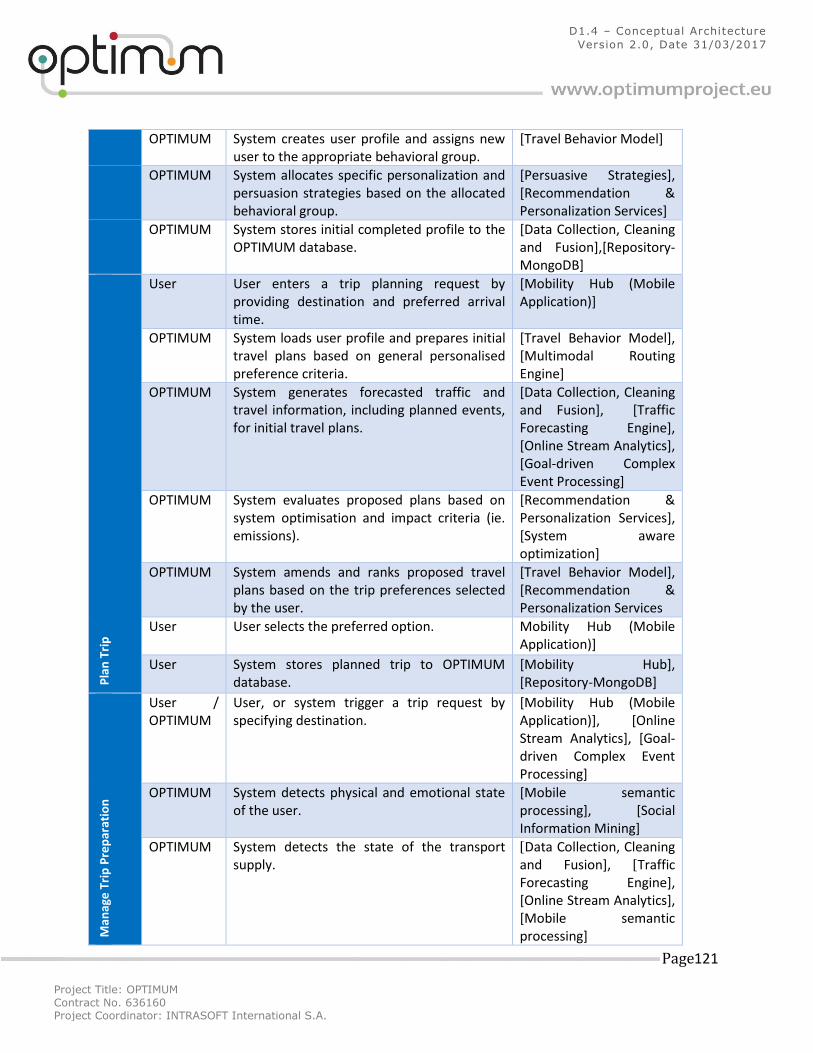
Project Title: OPTIMUM
Contract No. 636160 Project Coordinator: INTRASOFT International S.A.
Page 121
D1.4 – Conceptual Architecture
Version 2.0, Date 31/03/2017
OPTIMUM System creates user profile and assigns new user to the appropriate behavioral group.
[Travel Behavior Model]
OPTIMUM System allocates specific personalization and persuasion strategies based on the allocated behavioral group.
[Persuasive Strategies], [Recommendation & Personalization Services]
OPTIMUM System stores initial completed profile to the OPTIMUM database.
[Data Collection, Cleaning and Fusion],[Repository-MongoDB]
Pla
n T
rip
User User enters a trip planning request by providing destination and preferred arrival time.
[Mobility Hub (Mobile Application)]
OPTIMUM System loads user profile and prepares initial travel plans based on general personalised preference criteria.
[Travel Behavior Model], [Multimodal Routing Engine]
OPTIMUM System generates forecasted traffic and travel information, including planned events, for initial travel plans.
[Data Collection, Cleaning and Fusion], [Traffic Forecasting Engine], [Online Stream Analytics], [Goal-driven Complex Event Processing]
OPTIMUM System evaluates proposed plans based on system optimisation and impact criteria (ie. emissions).
[Recommendation & Personalization Services], [System aware optimization]
OPTIMUM System amends and ranks proposed travel plans based on the trip preferences selected by the user.
[Travel Behavior Model], [Recommendation & Personalization Services
User User selects the preferred option. Mobility Hub (Mobile Application)]
User System stores planned trip to OPTIMUM database.
[Mobility Hub], [Repository-MongoDB]
Man
age
Tri
p P
rep
arat
ion
User / OPTIMUM
User, or system trigger a trip request by specifying destination.
[Mobility Hub (Mobile Application)], [Online Stream Analytics], [Goal-driven Complex Event Processing]
OPTIMUM System detects physical and emotional state of the user.
[Mobile semantic processing], [Social Information Mining]
OPTIMUM System detects the state of the transport supply.
[Data Collection, Cleaning and Fusion], [Traffic Forecasting Engine], [Online Stream Analytics], [Mobile semantic processing]
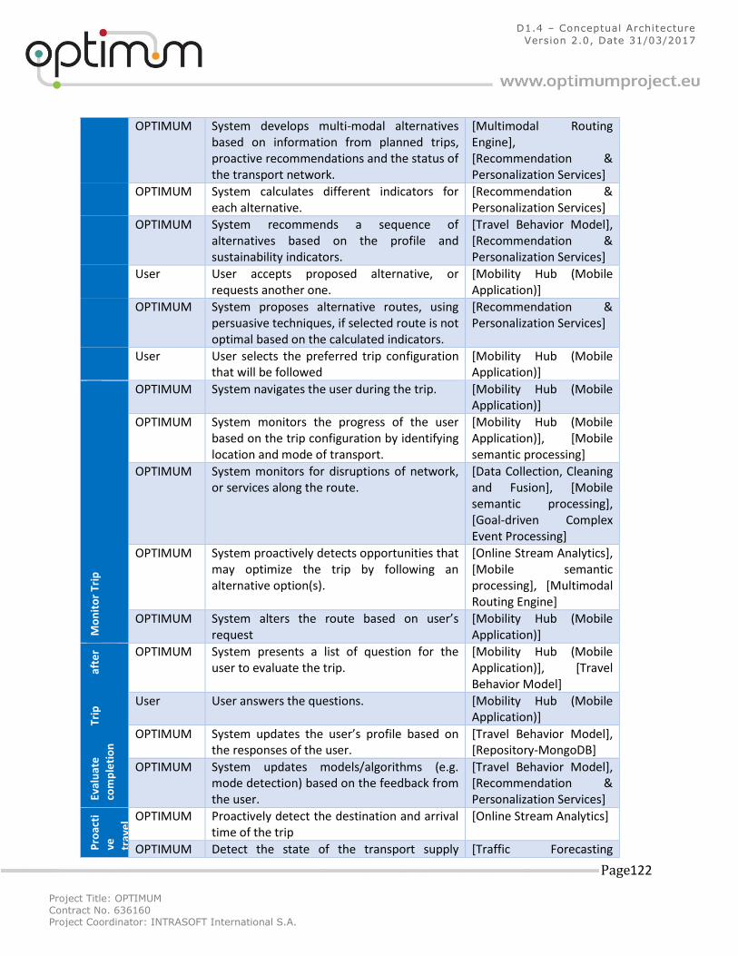
Project Title: OPTIMUM
Contract No. 636160 Project Coordinator: INTRASOFT International S.A.
Page 122
D1.4 – Conceptual Architecture
Version 2.0, Date 31/03/2017
OPTIMUM System develops multi-modal alternatives based on information from planned trips, proactive recommendations and the status of the transport network.
[Multimodal Routing Engine], [Recommendation & Personalization Services]
OPTIMUM System calculates different indicators for each alternative.
[Recommendation & Personalization Services]
OPTIMUM System recommends a sequence of alternatives based on the profile and sustainability indicators.
[Travel Behavior Model], [Recommendation & Personalization Services]
User User accepts proposed alternative, or requests another one.
[Mobility Hub (Mobile Application)]
OPTIMUM System proposes alternative routes, using persuasive techniques, if selected route is not optimal based on the calculated indicators.
[Recommendation & Personalization Services]
User User selects the preferred trip configuration that will be followed
[Mobility Hub (Mobile Application)]
Mo
nit
or
Trip
OPTIMUM System navigates the user during the trip. [Mobility Hub (Mobile Application)]
OPTIMUM System monitors the progress of the user based on the trip configuration by identifying location and mode of transport.
[Mobility Hub (Mobile Application)], [Mobile semantic processing]
OPTIMUM System monitors for disruptions of network, or services along the route.
[Data Collection, Cleaning and Fusion], [Mobile semantic processing], [Goal-driven Complex Event Processing]
OPTIMUM System proactively detects opportunities that may optimize the trip by following an alternative option(s).
[Online Stream Analytics], [Mobile semantic processing], [Multimodal Routing Engine]
OPTIMUM System alters the route based on user’s request
[Mobility Hub (Mobile Application)]
Eval
uat
e
Trip
af
ter
com
ple
tio
n
OPTIMUM System presents a list of question for the user to evaluate the trip.
[Mobility Hub (Mobile Application)], [Travel Behavior Model]
User User answers the questions. [Mobility Hub (Mobile Application)]
OPTIMUM System updates the user’s profile based on the responses of the user.
[Travel Behavior Model], [Repository-MongoDB]
OPTIMUM System updates models/algorithms (e.g. mode detection) based on the feedback from the user.
[Travel Behavior Model], [Recommendation & Personalization Services]
Pro
acti
ve
trav
el
sugg
es
tio
ns
OPTIMUM Proactively detect the destination and arrival time of the trip
[Online Stream Analytics]
OPTIMUM Detect the state of the transport supply [Traffic Forecasting
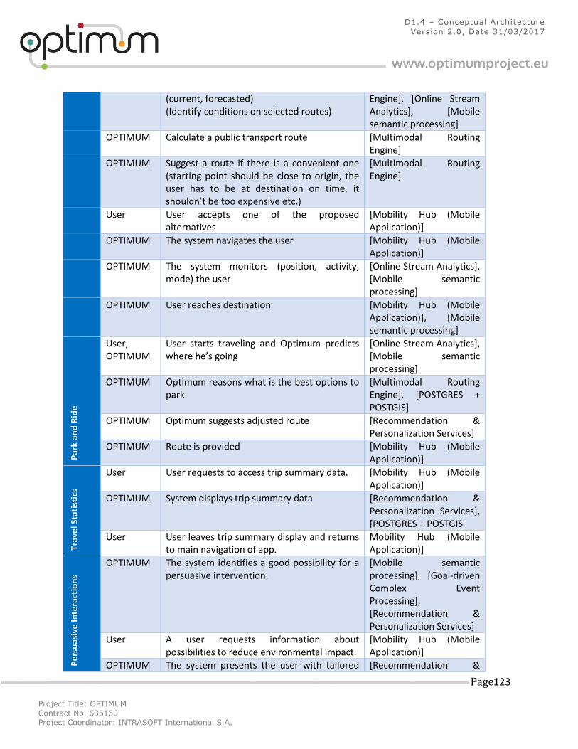
Project Title: OPTIMUM
Contract No. 636160 Project Coordinator: INTRASOFT International S.A.
Page 123
D1.4 – Conceptual Architecture
Version 2.0, Date 31/03/2017
(current, forecasted) (Identify conditions on selected routes)
Engine], [Online Stream Analytics], [Mobile semantic processing]
OPTIMUM Calculate a public transport route [Multimodal Routing Engine]
OPTIMUM Suggest a route if there is a convenient one (starting point should be close to origin, the user has to be at destination on time, it shouldn’t be too expensive etc.)
[Multimodal Routing Engine]
User User accepts one of the proposed alternatives
[Mobility Hub (Mobile Application)]
OPTIMUM The system navigates the user [Mobility Hub (Mobile Application)]
OPTIMUM The system monitors (position, activity, mode) the user
[Online Stream Analytics], [Mobile semantic processing]
OPTIMUM User reaches destination [Mobility Hub (Mobile Application)], [Mobile semantic processing]
Par
k an
d R
ide
User, OPTIMUM
User starts traveling and Optimum predicts where he’s going
[Online Stream Analytics], [Mobile semantic processing]
OPTIMUM Optimum reasons what is the best options to park
[Multimodal Routing Engine], [POSTGRES + POSTGIS]
OPTIMUM Optimum suggests adjusted route [Recommendation & Personalization Services]
OPTIMUM Route is provided [Mobility Hub (Mobile Application)]
Trav
el S
tati
stic
s
User User requests to access trip summary data. [Mobility Hub (Mobile Application)]
OPTIMUM System displays trip summary data [Recommendation & Personalization Services], [POSTGRES + POSTGIS
User User leaves trip summary display and returns to main navigation of app.
Mobility Hub (Mobile Application)]
Pe
rsu
asiv
e In
tera
ctio
ns
OPTIMUM The system identifies a good possibility for a persuasive intervention.
[Mobile semantic processing], [Goal-driven Complex Event Processing], [Recommendation & Personalization Services]
User A user requests information about possibilities to reduce environmental impact.
[Mobility Hub (Mobile Application)]
OPTIMUM The system presents the user with tailored [Recommendation &
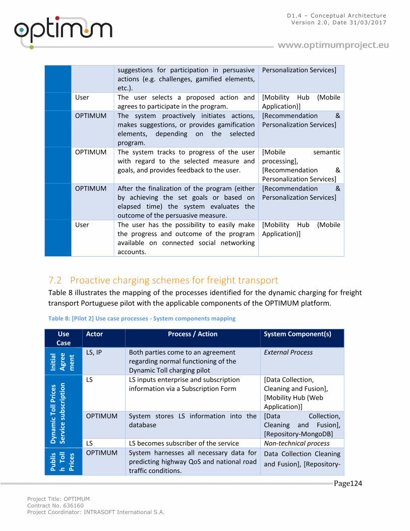
Project Title: OPTIMUM
Contract No. 636160 Project Coordinator: INTRASOFT International S.A.
Page 124
D1.4 – Conceptual Architecture
Version 2.0, Date 31/03/2017
suggestions for participation in persuasive actions (e.g. challenges, gamified elements, etc.).
Personalization Services]
User The user selects a proposed action and agrees to participate in the program.
[Mobility Hub (Mobile Application)]
OPTIMUM The system proactively initiates actions, makes suggestions, or provides gamification elements, depending on the selected program.
[Recommendation & Personalization Services]
OPTIMUM The system tracks to progress of the user with regard to the selected measure and goals, and provides feedback to the user.
[Mobile semantic processing], [Recommendation & Personalization Services]
OPTIMUM After the finalization of the program (either by achieving the set goals or based on elapsed time) the system evaluates the outcome of the persuasive measure.
[Recommendation & Personalization Services]
User The user has the possibility to easily make the progress and outcome of the program available on connected social networking accounts.
[Mobility Hub (Mobile Application)]
7.2 Proactive charging schemes for freight transport Table 8 illustrates the mapping of the processes identified for the dynamic charging for freight
transport Portuguese pilot with the applicable components of the OPTIMUM platform.
Table 8: [Pilot 2] Use case processes - System components mapping
Use Case
Actor Process / Action System Component(s)
Init
ial
Agr
eem
en
t LS, IP Both parties come to an agreement regarding normal functioning of the Dynamic Toll charging pilot
External Process
Dyn
amic
To
ll P
rice
s Se
rvic
e su
bsc
rip
tio
n LS LS inputs enterprise and subscription
information via a Subscription Form [Data Collection, Cleaning and Fusion], [Mobility Hub (Web Application)]
OPTIMUM System stores LS information into the database
[Data Collection, Cleaning and Fusion], [Repository-MongoDB]
LS LS becomes subscriber of the service Non-technical process
Pu
blis
h
Toll
Pri
ces OPTIMUM System harnesses all necessary data for
predicting highway QoS and national road traffic conditions.
Data Collection Cleaning
and Fusion], [Repository-
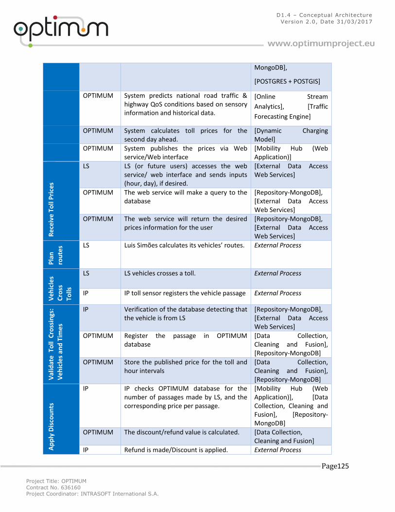
Project Title: OPTIMUM
Contract No. 636160 Project Coordinator: INTRASOFT International S.A.
Page 125
D1.4 – Conceptual Architecture
Version 2.0, Date 31/03/2017
MongoDB],
[POSTGRES + POSTGIS]
OPTIMUM System predicts national road traffic & highway QoS conditions based on sensory information and historical data.
[Online Stream
Analytics], [Traffic
Forecasting Engine]
OPTIMUM System calculates toll prices for the second day ahead.
[Dynamic Charging Model]
OPTIMUM System publishes the prices via Web service/Web interface
[Mobility Hub (Web Application)]
Re
ceiv
e T
oll
Pri
ces
LS LS (or future users) accesses the web service/ web interface and sends inputs (hour, day), if desired.
[External Data Access Web Services]
OPTIMUM The web service will make a query to the database
[Repository-MongoDB], [External Data Access Web Services]
OPTIMUM The web service will return the desired prices information for the user
[Repository-MongoDB], [External Data Access Web Services]
Pla
n
rou
tes LS Luis Simões calculates its vehicles’ routes. External Process
Ve
hic
les
Cro
ss
Tolls
LS LS vehicles crosses a toll. External Process
IP IP toll sensor registers the vehicle passage External Process
Val
idat
e T
oll
Cro
ssin
gs:
Veh
icle
s an
d T
ime
s
IP Verification of the database detecting that the vehicle is from LS
[Repository-MongoDB], [External Data Access Web Services]
OPTIMUM Register the passage in OPTIMUM database
[Data Collection, Cleaning and Fusion], [Repository-MongoDB]
OPTIMUM Store the published price for the toll and hour intervals
[Data Collection, Cleaning and Fusion], [Repository-MongoDB]
Ap
ply
Dis
cou
nts
IP IP checks OPTIMUM database for the number of passages made by LS, and the corresponding price per passage.
[Mobility Hub (Web Application)], [Data Collection, Cleaning and Fusion], [Repository-MongoDB]
OPTIMUM The discount/refund value is calculated. [Data Collection, Cleaning and Fusion]
IP Refund is made/Discount is applied. External Process
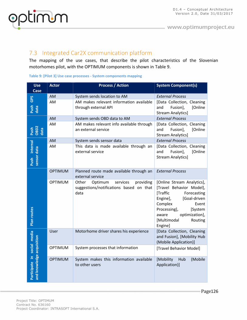
Project Title: OPTIMUM
Contract No. 636160 Project Coordinator: INTRASOFT International S.A.
Page 126
D1.4 – Conceptual Architecture
Version 2.0, Date 31/03/2017
7.3 Integrated Car2X communication platform The mapping of the use cases, that describe the pilot characteristics of the Slovenian
motorhomes pilot, with the OPTIMUM components is shown in Table 9.
Table 9: [Pilot 3] Use case processes - System components mapping
Use Case
Actor Process / Action System Component(s)
Pu
sh
GP
S
dat
a
AM System sends location to AM External Process
AM AM makes relevant information available through external API
[Data Collection, Cleaning and Fusion], [Online Stream Analytics]
Pu
sh
OB
D2
dat
a
AM System sends OBD data to AM External Process
AM AM makes relevant info available through an external service
[Data Collection, Cleaning and Fusion], [Online Stream Analytics]
Pu
sh
inte
rnal
sen
sor
dat
a
AM System sends sensor data External Process
AM This data is made available through an external service
[Data Collection, Cleaning and Fusion], [Online Stream Analytics]
Pla
n r
ou
tes
OPTIMUM Planned route made available through an external service
External Process
OPTIMUM Other Optimum services providing suggestions/notifications based on that data
[Online Stream Analytics], [Travel Behavior Model], [Traffic Forecasting Engine], [Goal-driven Complex Event Processing], [System aware optimization], [Multimodal Routing Engine]
Par
tici
pat
e
in
soci
al
me
dia
and
kn
ow
led
ge a
cqu
isit
ion
User Motorhome driver shares his experience [Data Collection, Cleaning and Fusion], [Mobility Hub (Mobile Application)]
OPTIMUM System processes that information [Travel Behavior Model]
OPTIMUM System makes this information available to other users
[Mobility Hub (Mobile Application)]
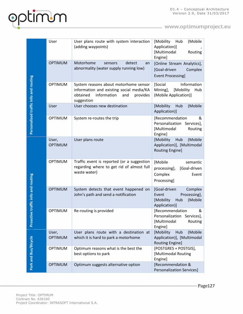
Project Title: OPTIMUM
Contract No. 636160 Project Coordinator: INTRASOFT International S.A.
Page 127
D1.4 – Conceptual Architecture
Version 2.0, Date 31/03/2017
Pe
rso
nal
ize
d t
raff
ic in
fo a
nd
ro
uti
ng
User User plans route with system interaction (adding waypoints)
[Mobility Hub (Mobile Application)] , [Multimodal Routing Engine]
OPTIMUM Motorhome sensors detect an abnormality (water supply running low)
[Online Stream Analytics],
[Goal-driven Complex
Event Processing]
OPTIMUM System reasons about motorhome sensor information and existing social media/KA obtained information and provides suggestion
[Social Information Mining], [Mobility Hub (Mobile Application)]
User User chooses new destination [Mobility Hub (Mobile Application)]
OPTIMUM System re-routes the trip [Recommendation & Personalization Services], [Multimodal Routing Engine]
Pro
acti
ve t
raff
ic in
fo a
nd
ro
uti
ng
User, OPTIMUM
User plans route [Mobility Hub (Mobile Application)], [Multimodal Routing Engine]
OPTIMUM Traffic event is reported (or a suggestion regarding where to get rid of almost full waste water)
[Mobile semantic
processing], [Goal-driven
Complex Event
Processing]
OPTIMUM System detects that event happened on John’s path and send a notification
[Goal-driven Complex Event Processing], [Mobility Hub (Mobile Application)]
OPTIMUM Re-routing is provided [Recommendation & Personalization Services], [Multimodal Routing Engine]
Par
k an
d B
us/
Bic
ycle
User, OPTIMUM
User plans route with a destination at which it is hard to park a motorhome
[Mobility Hub (Mobile Application)], [Multimodal Routing Engine]
OPTIMUM Optimum reasons what is the best the best options to park
[POSTGRES + POSTGIS], [Multimodal Routing Engine]
OPTIMUM Optimum suggests alternative option [Recommendation & Personalization Services]
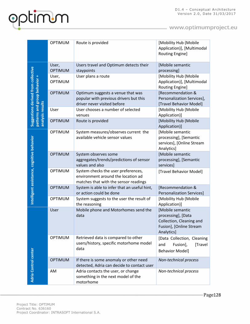
Project Title: OPTIMUM
Contract No. 636160 Project Coordinator: INTRASOFT International S.A.
Page 128
D1.4 – Conceptual Architecture
Version 2.0, Date 31/03/2017
OPTIMUM Route is provided [Mobility Hub (Mobile Application)], [Multimodal Routing Engine]
Sugg
est
ion
s d
eri
ved
fro
m c
olle
ctiv
e
pat
tern
s an
d g
rou
p b
eh
avio
r +
anal
ysis
re
sult
s
User, OPTIMUM
Users travel and Optimum detects their staypoints
[Mobile semantic processing]
User, OPTIMUM
User plans a route [Mobility Hub (Mobile Application)], [Multimodal Routing Engine]
OPTIMUM Optimum suggests a venue that was popular with previous drivers but this driver never visited before
[Recommendation & Personalization Services], [Travel Behavior Model]
User User chooses a number of selected venues
[Mobility Hub (Mobile Application)]
OPTIMUM Route is provided [Mobility Hub (Mobile Application)]
Inte
llige
nt
assi
stan
ce, c
ogn
itiv
e b
eh
avio
r
OPTIMUM System measures/observes current the available vehicle sensor values
[Mobile semantic processing], [Semantic services], [Online Stream Analytics]
OPTIMUM System observes some aggregates/trends/predictions of sensor values and also
[Mobile semantic processing], [Semantic services]
OPTIMUM System checks the user preferences, environment around the location ad matches that with the sensor readings
[Travel Behavior Model]
OPTIMUM System is able to infer that an useful hint, or action could be done
[Recommendation & Personalization Services]
OPTIMUM System suggests to the user the result of the reasoning
[Mobility Hub (Mobile Application)]
Ad
ria
Co
ntr
ol c
en
ter
User Mobile phone and Motorhomes send the data
[Mobile semantic processing], [Data Collection, Cleaning and Fusion], [Online Stream Analytics]
OPTIMUM Retrieved data is compared to other users/history, specific motorhome model data
[Data Collection, Cleaning
and Fusion], [Travel
Behavior Model]
OPTIMUM If there is some anomaly or other need detected, Adria can decide to contact user
Non-technical process
AM Adria contacts the user, or change something in the next model of the motorhome
Non-technical process
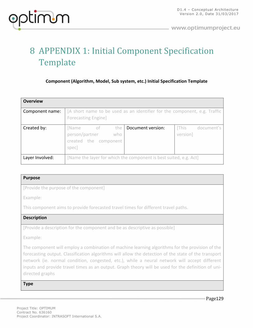
Project Title: OPTIMUM
Contract No. 636160 Project Coordinator: INTRASOFT International S.A.
Page 129
D1.4 – Conceptual Architecture
Version 2.0, Date 31/03/2017
8 APPENDIX 1: Initial Component Specification
Template
Component (Algorithm, Model, Sub system, etc.) Initial Specification Template
Overview
Component name: [A short name to be used as an identifier for the component, e.g. Traffic
Forecasting Engine]
Created by: [Name of the
person/partner who
created the component
spec]
Document version: [This document’s
version]
Layer Involved: [Name the layer for which the component is best suited, e.g. Act]
Purpose
[Provide the purpose of the component]
Example:
This component aims to provide forecasted travel times for different travel paths.
Description
[Provide a description for the component and be as descriptive as possible]
Example:
The component will employ a combination of machine learning algorithms for the provision of the
forecasting output. Classification algorithms will allow the detection of the state of the transport
network (ie. normal condition, congested, etc.), while a neural network will accept different
inputs and provide travel times as an output. Graph theory will be used for the definition of uni-
directed graphs
Type
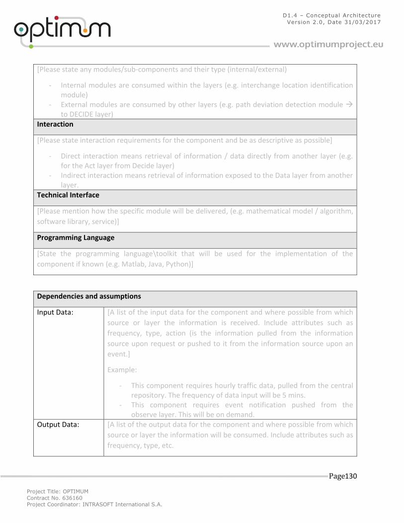
Project Title: OPTIMUM
Contract No. 636160 Project Coordinator: INTRASOFT International S.A.
Page 130
D1.4 – Conceptual Architecture
Version 2.0, Date 31/03/2017
[Please state any modules/sub-components and their type (internal/external)
- Internal modules are consumed within the layers (e.g. interchange location identification module)
- External modules are consumed by other layers (e.g. path deviation detection module to DECIDE layer)
Interaction
[Please state interaction requirements for the component and be as descriptive as possible]
- Direct interaction means retrieval of information / data directly from another layer (e.g. for the Act layer from Decide layer)
- Indirect interaction means retrieval of information exposed to the Data layer from another layer.
Technical Interface
[Please mention how the specific module will be delivered, (e.g. mathematical model / algorithm,
software library, service)]
Programming Language
[State the programming language\toolkit that will be used for the implementation of the
component if known (e.g. Matlab, Java, Python)]
Dependencies and assumptions
Input Data: [A list of the input data for the component and where possible from which
source or layer the information is received. Include attributes such as
frequency, type, action (is the information pulled from the information
source upon request or pushed to it from the information source upon an
event.]
Example:
- This component requires hourly traffic data, pulled from the central repository. The frequency of data input will be 5 mins.
- This component requires event notification pushed from the observe layer. This will be on demand.
Output Data: [A list of the output data for the component and where possible from which
source or layer the information will be consumed. Include attributes such as
frequency, type, etc.
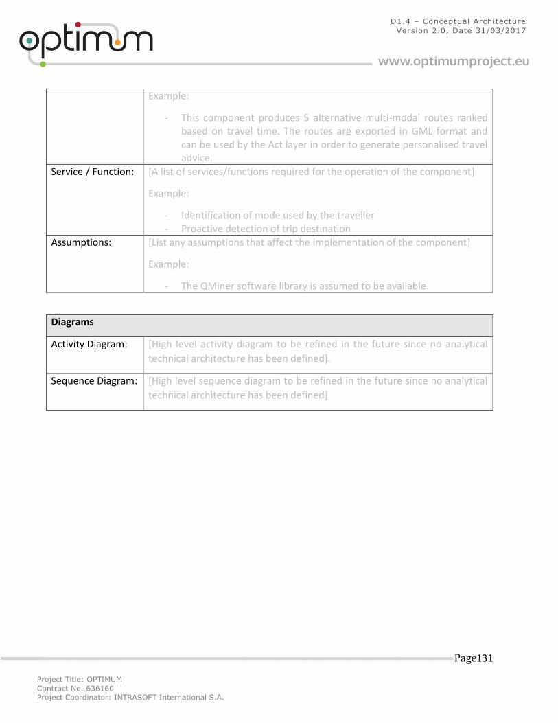
Project Title: OPTIMUM
Contract No. 636160 Project Coordinator: INTRASOFT International S.A.
Page 131
D1.4 – Conceptual Architecture
Version 2.0, Date 31/03/2017
Example:
- This component produces 5 alternative multi-modal routes ranked based on travel time. The routes are exported in GML format and can be used by the Act layer in order to generate personalised travel advice.
Service / Function: [A list of services/functions required for the operation of the component]
Example:
- Identification of mode used by the traveller - Proactive detection of trip destination
Assumptions: [List any assumptions that affect the implementation of the component]
Example:
- The QMiner software library is assumed to be available.
Diagrams
Activity Diagram: [High level activity diagram to be refined in the future since no analytical
technical architecture has been defined].
Sequence Diagram: [High level sequence diagram to be refined in the future since no analytical
technical architecture has been defined]
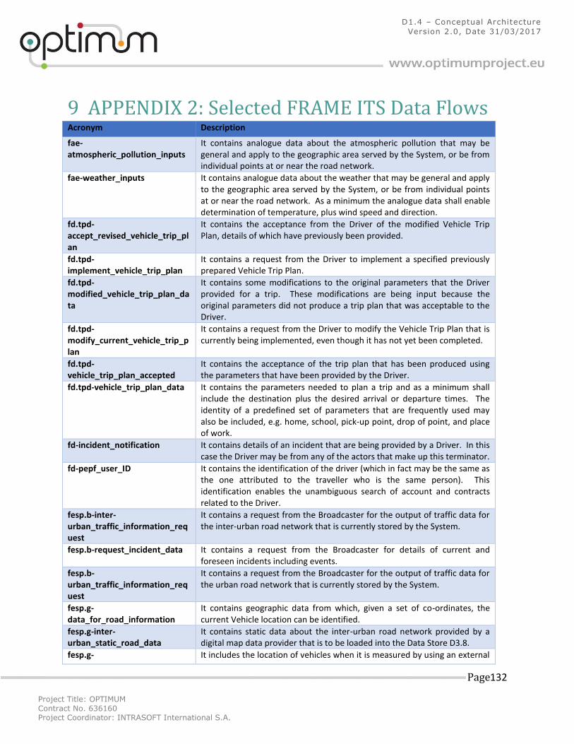
Project Title: OPTIMUM
Contract No. 636160 Project Coordinator: INTRASOFT International S.A.
Page 132
D1.4 – Conceptual Architecture
Version 2.0, Date 31/03/2017
9 APPENDIX 2: Selected FRAME ITS Data Flows Acronym Description
fae-atmospheric_pollution_inputs
It contains analogue data about the atmospheric pollution that may be general and apply to the geographic area served by the System, or be from individual points at or near the road network.
fae-weather_inputs It contains analogue data about the weather that may be general and apply to the geographic area served by the System, or be from individual points at or near the road network. As a minimum the analogue data shall enable determination of temperature, plus wind speed and direction.
fd.tpd-accept_revised_vehicle_trip_plan
It contains the acceptance from the Driver of the modified Vehicle Trip Plan, details of which have previously been provided.
fd.tpd-implement_vehicle_trip_plan
It contains a request from the Driver to implement a specified previously prepared Vehicle Trip Plan.
fd.tpd-modified_vehicle_trip_plan_data
It contains some modifications to the original parameters that the Driver provided for a trip. These modifications are being input because the original parameters did not produce a trip plan that was acceptable to the Driver.
fd.tpd-modify_current_vehicle_trip_plan
It contains a request from the Driver to modify the Vehicle Trip Plan that is currently being implemented, even though it has not yet been completed.
fd.tpd-vehicle_trip_plan_accepted
It contains the acceptance of the trip plan that has been produced using the parameters that have been provided by the Driver.
fd.tpd-vehicle_trip_plan_data It contains the parameters needed to plan a trip and as a minimum shall include the destination plus the desired arrival or departure times. The identity of a predefined set of parameters that are frequently used may also be included, e.g. home, school, pick-up point, drop of point, and place of work.
fd-incident_notification It contains details of an incident that are being provided by a Driver. In this case the Driver may be from any of the actors that make up this terminator.
fd-pepf_user_ID It contains the identification of the driver (which in fact may be the same as the one attributed to the traveller who is the same person). This identification enables the unambiguous search of account and contracts related to the Driver.
fesp.b-inter-urban_traffic_information_request
It contains a request from the Broadcaster for the output of traffic data for the inter-urban road network that is currently stored by the System.
fesp.b-request_incident_data It contains a request from the Broadcaster for details of current and foreseen incidents including events.
fesp.b-urban_traffic_information_request
It contains a request from the Broadcaster for the output of traffic data for the urban road network that is currently stored by the System.
fesp.g-data_for_road_information
It contains geographic data from which, given a set of co-ordinates, the current Vehicle location can be identified.
fesp.g-inter-urban_static_road_data
It contains static data about the inter-urban road network provided by a digital map data provider that is to be loaded into the Data Store D3.8.
fesp.g- It includes the location of vehicles when it is measured by using an external
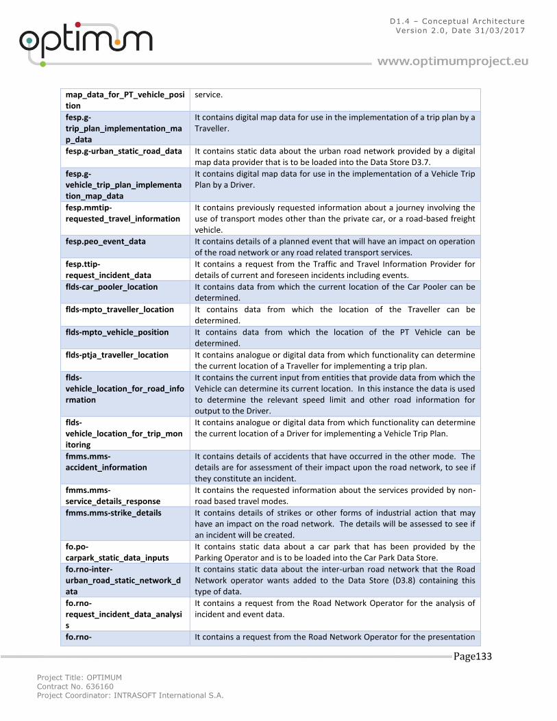
Project Title: OPTIMUM
Contract No. 636160 Project Coordinator: INTRASOFT International S.A.
Page 133
D1.4 – Conceptual Architecture
Version 2.0, Date 31/03/2017
map_data_for_PT_vehicle_position
service.
fesp.g-trip_plan_implementation_map_data
It contains digital map data for use in the implementation of a trip plan by a Traveller.
fesp.g-urban_static_road_data It contains static data about the urban road network provided by a digital map data provider that is to be loaded into the Data Store D3.7.
fesp.g-vehicle_trip_plan_implementation_map_data
It contains digital map data for use in the implementation of a Vehicle Trip Plan by a Driver.
fesp.mmtip-requested_travel_information
It contains previously requested information about a journey involving the use of transport modes other than the private car, or a road-based freight vehicle.
fesp.peo_event_data It contains details of a planned event that will have an impact on operation of the road network or any road related transport services.
fesp.ttip-request_incident_data
It contains a request from the Traffic and Travel Information Provider for details of current and foreseen incidents including events.
flds-car_pooler_location It contains data from which the current location of the Car Pooler can be determined.
flds-mpto_traveller_location It contains data from which the location of the Traveller can be determined.
flds-mpto_vehicle_position It contains data from which the location of the PT Vehicle can be determined.
flds-ptja_traveller_location It contains analogue or digital data from which functionality can determine the current location of a Traveller for implementing a trip plan.
flds-vehicle_location_for_road_information
It contains the current input from entities that provide data from which the Vehicle can determine its current location. In this instance the data is used to determine the relevant speed limit and other road information for output to the Driver.
flds-vehicle_location_for_trip_monitoring
It contains analogue or digital data from which functionality can determine the current location of a Driver for implementing a Vehicle Trip Plan.
fmms.mms-accident_information
It contains details of accidents that have occurred in the other mode. The details are for assessment of their impact upon the road network, to see if they constitute an incident.
fmms.mms-service_details_response
It contains the requested information about the services provided by non-road based travel modes.
fmms.mms-strike_details It contains details of strikes or other forms of industrial action that may have an impact on the road network. The details will be assessed to see if an incident will be created.
fo.po-carpark_static_data_inputs
It contains static data about a car park that has been provided by the Parking Operator and is to be loaded into the Car Park Data Store.
fo.rno-inter-urban_road_static_network_data
It contains static data about the inter-urban road network that the Road Network operator wants added to the Data Store (D3.8) containing this type of data.
fo.rno-request_incident_data_analysis
It contains a request from the Road Network Operator for the analysis of incident and event data.
fo.rno- It contains a request from the Road Network Operator for the presentation
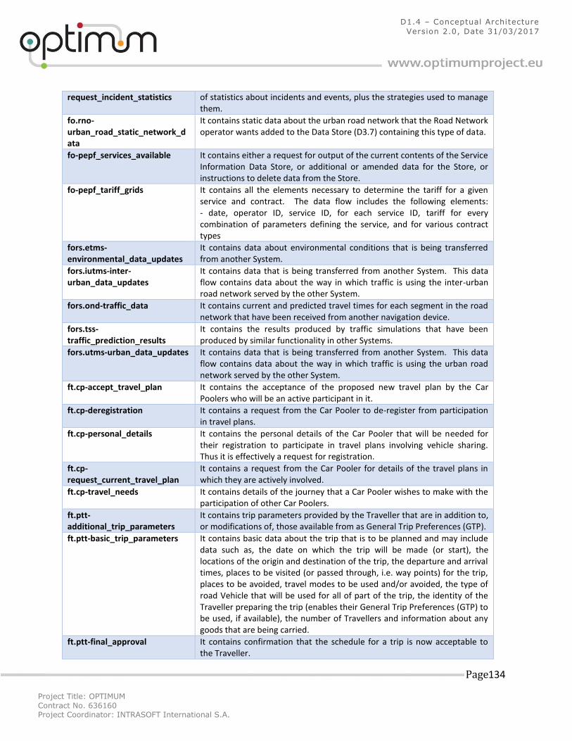
Project Title: OPTIMUM
Contract No. 636160 Project Coordinator: INTRASOFT International S.A.
Page 134
D1.4 – Conceptual Architecture
Version 2.0, Date 31/03/2017
request_incident_statistics of statistics about incidents and events, plus the strategies used to manage them.
fo.rno-urban_road_static_network_data
It contains static data about the urban road network that the Road Network operator wants added to the Data Store (D3.7) containing this type of data.
fo-pepf_services_available It contains either a request for output of the current contents of the Service Information Data Store, or additional or amended data for the Store, or instructions to delete data from the Store.
fo-pepf_tariff_grids It contains all the elements necessary to determine the tariff for a given service and contract. The data flow includes the following elements: - date, operator ID, service ID, for each service ID, tariff for every combination of parameters defining the service, and for various contract types
fors.etms-environmental_data_updates
It contains data about environmental conditions that is being transferred from another System.
fors.iutms-inter-urban_data_updates
It contains data that is being transferred from another System. This data flow contains data about the way in which traffic is using the inter-urban road network served by the other System.
fors.ond-traffic_data It contains current and predicted travel times for each segment in the road network that have been received from another navigation device.
fors.tss-traffic_prediction_results
It contains the results produced by traffic simulations that have been produced by similar functionality in other Systems.
fors.utms-urban_data_updates It contains data that is being transferred from another System. This data flow contains data about the way in which traffic is using the urban road network served by the other System.
ft.cp-accept_travel_plan It contains the acceptance of the proposed new travel plan by the Car Poolers who will be an active participant in it.
ft.cp-deregistration It contains a request from the Car Pooler to de-register from participation in travel plans.
ft.cp-personal_details It contains the personal details of the Car Pooler that will be needed for their registration to participate in travel plans involving vehicle sharing. Thus it is effectively a request for registration.
ft.cp-request_current_travel_plan
It contains a request from the Car Pooler for details of the travel plans in which they are actively involved.
ft.cp-travel_needs It contains details of the journey that a Car Pooler wishes to make with the participation of other Car Poolers.
ft.ptt-additional_trip_parameters
It contains trip parameters provided by the Traveller that are in addition to, or modifications of, those available from as General Trip Preferences (GTP).
ft.ptt-basic_trip_parameters It contains basic data about the trip that is to be planned and may include data such as, the date on which the trip will be made (or start), the locations of the origin and destination of the trip, the departure and arrival times, places to be visited (or passed through, i.e. way points) for the trip, places to be avoided, travel modes to be used and/or avoided, the type of road Vehicle that will be used for all of part of the trip, the identity of the Traveller preparing the trip (enables their General Trip Preferences (GTP) to be used, if available), the number of Travellers and information about any goods that are being carried.
ft.ptt-final_approval It contains confirmation that the schedule for a trip is now acceptable to the Traveller.
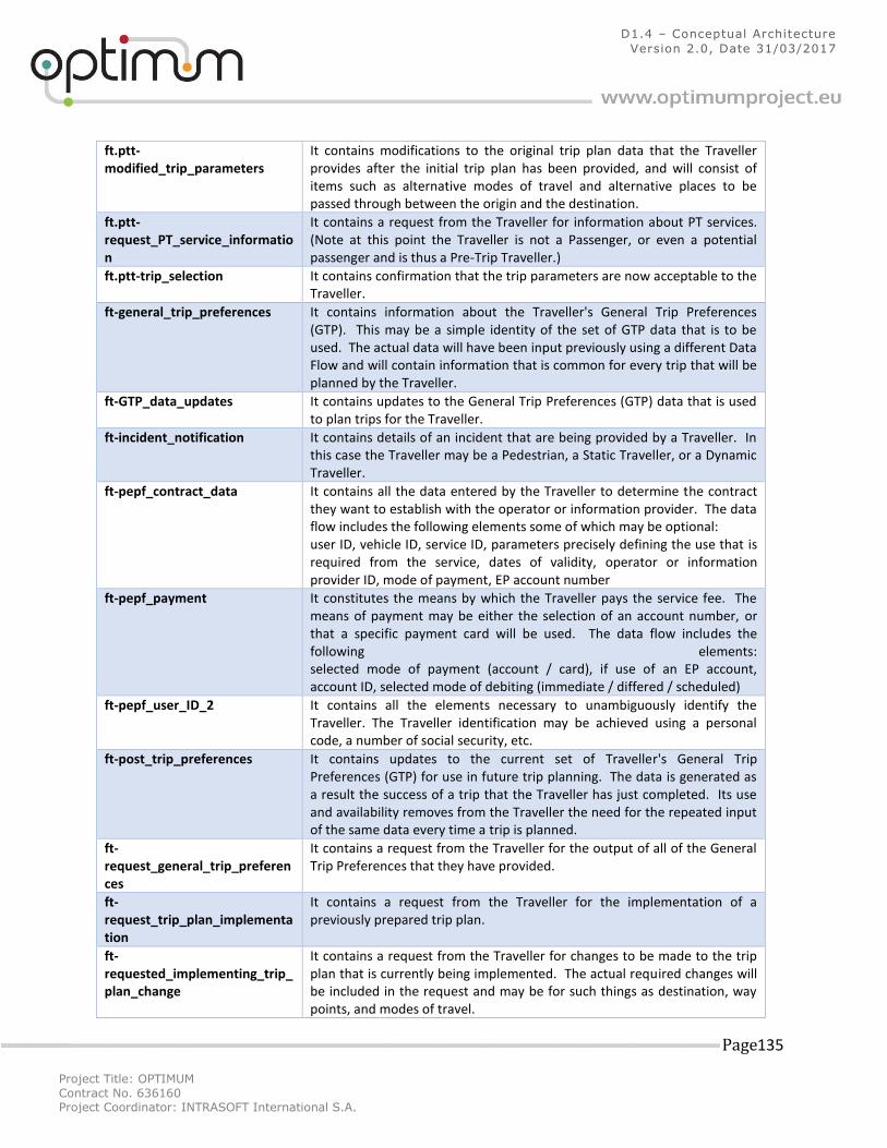
Project Title: OPTIMUM
Contract No. 636160 Project Coordinator: INTRASOFT International S.A.
Page 135
D1.4 – Conceptual Architecture
Version 2.0, Date 31/03/2017
ft.ptt-modified_trip_parameters
It contains modifications to the original trip plan data that the Traveller provides after the initial trip plan has been provided, and will consist of items such as alternative modes of travel and alternative places to be passed through between the origin and the destination.
ft.ptt-request_PT_service_information
It contains a request from the Traveller for information about PT services. (Note at this point the Traveller is not a Passenger, or even a potential passenger and is thus a Pre-Trip Traveller.)
ft.ptt-trip_selection It contains confirmation that the trip parameters are now acceptable to the Traveller.
ft-general_trip_preferences It contains information about the Traveller's General Trip Preferences (GTP). This may be a simple identity of the set of GTP data that is to be used. The actual data will have been input previously using a different Data Flow and will contain information that is common for every trip that will be planned by the Traveller.
ft-GTP_data_updates It contains updates to the General Trip Preferences (GTP) data that is used to plan trips for the Traveller.
ft-incident_notification It contains details of an incident that are being provided by a Traveller. In this case the Traveller may be a Pedestrian, a Static Traveller, or a Dynamic Traveller.
ft-pepf_contract_data It contains all the data entered by the Traveller to determine the contract they want to establish with the operator or information provider. The data flow includes the following elements some of which may be optional: user ID, vehicle ID, service ID, parameters precisely defining the use that is required from the service, dates of validity, operator or information provider ID, mode of payment, EP account number
ft-pepf_payment It constitutes the means by which the Traveller pays the service fee. The means of payment may be either the selection of an account number, or that a specific payment card will be used. The data flow includes the following elements: selected mode of payment (account / card), if use of an EP account, account ID, selected mode of debiting (immediate / differed / scheduled)
ft-pepf_user_ID_2 It contains all the elements necessary to unambiguously identify the Traveller. The Traveller identification may be achieved using a personal code, a number of social security, etc.
ft-post_trip_preferences It contains updates to the current set of Traveller's General Trip Preferences (GTP) for use in future trip planning. The data is generated as a result the success of a trip that the Traveller has just completed. Its use and availability removes from the Traveller the need for the repeated input of the same data every time a trip is planned.
ft-request_general_trip_preferences
It contains a request from the Traveller for the output of all of the General Trip Preferences that they have provided.
ft-request_trip_plan_implementation
It contains a request from the Traveller for the implementation of a previously prepared trip plan.
ft-requested_implementing_trip_plan_change
It contains a request from the Traveller for changes to be made to the trip plan that is currently being implemented. The actual required changes will be included in the request and may be for such things as destination, way points, and modes of travel.
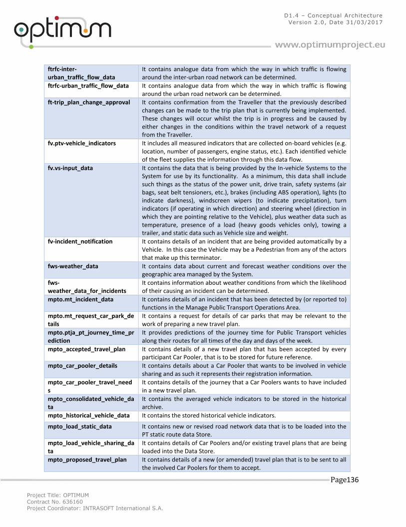
Project Title: OPTIMUM
Contract No. 636160 Project Coordinator: INTRASOFT International S.A.
Page 136
D1.4 – Conceptual Architecture
Version 2.0, Date 31/03/2017
ftrfc-inter-urban_traffic_flow_data
It contains analogue data from which the way in which traffic is flowing around the inter-urban road network can be determined.
ftrfc-urban_traffic_flow_data It contains analogue data from which the way in which traffic is flowing around the urban road network can be determined.
ft-trip_plan_change_approval It contains confirmation from the Traveller that the previously described changes can be made to the trip plan that is currently being implemented. These changes will occur whilst the trip is in progress and be caused by either changes in the conditions within the travel network of a request from the Traveller.
fv.ptv-vehicle_indicators It includes all measured indicators that are collected on-board vehicles (e.g. location, number of passengers, engine status, etc.). Each identified vehicle of the fleet supplies the information through this data flow.
fv.vs-input_data It contains the data that is being provided by the In-vehicle Systems to the System for use by its functionality. As a minimum, this data shall include such things as the status of the power unit, drive train, safety systems (air bags, seat belt tensioners, etc.), brakes (including ABS operation), lights (to indicate darkness), windscreen wipers (to indicate precipitation), turn indicators (if operating in which direction) and steering wheel (direction in which they are pointing relative to the Vehicle), plus weather data such as temperature, presence of a load (heavy goods vehicles only), towing a trailer, and static data such as Vehicle size and weight.
fv-incident_notification It contains details of an incident that are being provided automatically by a Vehicle. In this case the Vehicle may be a Pedestrian from any of the actors that make up this terminator.
fws-weather_data It contains data about current and forecast weather conditions over the geographic area managed by the System.
fws-weather_data_for_incidents
It contains information about weather conditions from which the likelihood of their causing an incident can be determined.
mpto.mt_incident_data It contains details of an incident that has been detected by (or reported to) functions in the Manage Public Transport Operations Area.
mpto.mt_request_car_park_details
It contains a request for details of car parks that may be relevant to the work of preparing a new travel plan.
mpto.ptja_pt_journey_time_prediction
It provides predictions of the journey time for Public Transport vehicles along their routes for all times of the day and days of the week.
mpto_accepted_travel_plan It contains details of a new travel plan that has been accepted by every participant Car Pooler, that is to be stored for future reference.
mpto_car_pooler_details It contains details about a Car Pooler that wants to be involved in vehicle sharing and as such it represents their registration information.
mpto_car_pooler_travel_needs
It contains details of the journey that a Car Poolers wants to have included in a new travel plan.
mpto_consolidated_vehicle_data
It contains the averaged vehicle indicators to be stored in the historical archive.
mpto_historical_vehicle_data It contains the stored historical vehicle indicators.
mpto_load_static_data It contains new or revised road network data that is to be loaded into the PT static route data Store.
mpto_load_vehicle_sharing_data
It contains details of Car Poolers and/or existing travel plans that are being loaded into the Data Store.
mpto_proposed_travel_plan It contains details of a new (or amended) travel plan that is to be sent to all the involved Car Poolers for them to accept.
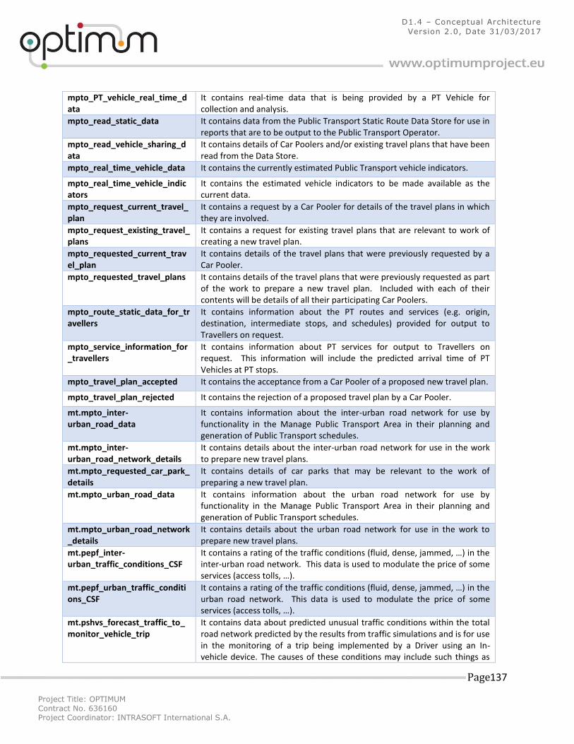
Project Title: OPTIMUM
Contract No. 636160 Project Coordinator: INTRASOFT International S.A.
Page 137
D1.4 – Conceptual Architecture
Version 2.0, Date 31/03/2017
mpto_PT_vehicle_real_time_data
It contains real-time data that is being provided by a PT Vehicle for collection and analysis.
mpto_read_static_data It contains data from the Public Transport Static Route Data Store for use in reports that are to be output to the Public Transport Operator.
mpto_read_vehicle_sharing_data
It contains details of Car Poolers and/or existing travel plans that have been read from the Data Store.
mpto_real_time_vehicle_data It contains the currently estimated Public Transport vehicle indicators.
mpto_real_time_vehicle_indicators
It contains the estimated vehicle indicators to be made available as the current data.
mpto_request_current_travel_plan
It contains a request by a Car Pooler for details of the travel plans in which they are involved.
mpto_request_existing_travel_plans
It contains a request for existing travel plans that are relevant to work of creating a new travel plan.
mpto_requested_current_travel_plan
It contains details of the travel plans that were previously requested by a Car Pooler.
mpto_requested_travel_plans It contains details of the travel plans that were previously requested as part of the work to prepare a new travel plan. Included with each of their contents will be details of all their participating Car Poolers.
mpto_route_static_data_for_travellers
It contains information about the PT routes and services (e.g. origin, destination, intermediate stops, and schedules) provided for output to Travellers on request.
mpto_service_information_for_travellers
It contains information about PT services for output to Travellers on request. This information will include the predicted arrival time of PT Vehicles at PT stops.
mpto_travel_plan_accepted It contains the acceptance from a Car Pooler of a proposed new travel plan.
mpto_travel_plan_rejected It contains the rejection of a proposed travel plan by a Car Pooler.
mt.mpto_inter-urban_road_data
It contains information about the inter-urban road network for use by functionality in the Manage Public Transport Area in their planning and generation of Public Transport schedules.
mt.mpto_inter-urban_road_network_details
It contains details about the inter-urban road network for use in the work to prepare new travel plans.
mt.mpto_requested_car_park_details
It contains details of car parks that may be relevant to the work of preparing a new travel plan.
mt.mpto_urban_road_data It contains information about the urban road network for use by functionality in the Manage Public Transport Area in their planning and generation of Public Transport schedules.
mt.mpto_urban_road_network_details
It contains details about the urban road network for use in the work to prepare new travel plans.
mt.pepf_inter-urban_traffic_conditions_CSF
It contains a rating of the traffic conditions (fluid, dense, jammed, …) in the inter-urban road network. This data is used to modulate the price of some services (access tolls, …).
mt.pepf_urban_traffic_conditions_CSF
It contains a rating of the traffic conditions (fluid, dense, jammed, …) in the urban road network. This data is used to modulate the price of some services (access tolls, …).
mt.pshvs_forecast_traffic_to_monitor_vehicle_trip
It contains data about predicted unusual traffic conditions within the total road network predicted by the results from traffic simulations and is for use in the monitoring of a trip being implemented by a Driver using an In-vehicle device. The causes of these conditions may include such things as
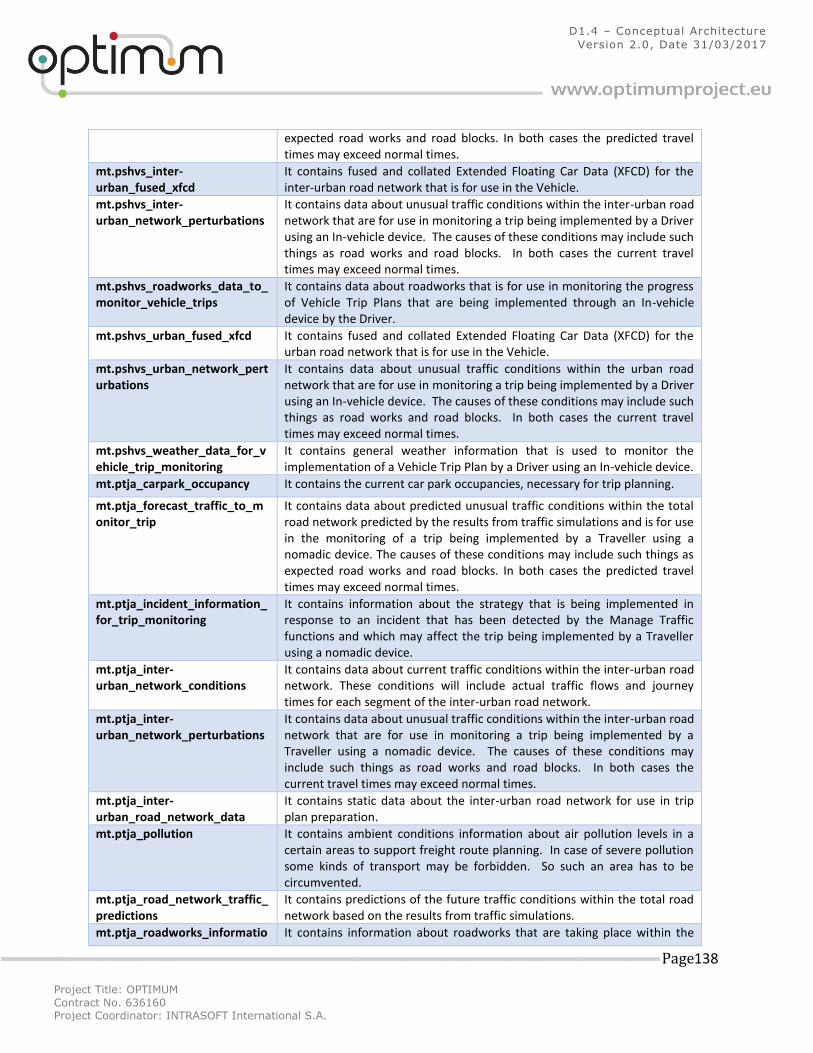
Project Title: OPTIMUM
Contract No. 636160 Project Coordinator: INTRASOFT International S.A.
Page 138
D1.4 – Conceptual Architecture
Version 2.0, Date 31/03/2017
expected road works and road blocks. In both cases the predicted travel times may exceed normal times.
mt.pshvs_inter-urban_fused_xfcd
It contains fused and collated Extended Floating Car Data (XFCD) for the inter-urban road network that is for use in the Vehicle.
mt.pshvs_inter-urban_network_perturbations
It contains data about unusual traffic conditions within the inter-urban road network that are for use in monitoring a trip being implemented by a Driver using an In-vehicle device. The causes of these conditions may include such things as road works and road blocks. In both cases the current travel times may exceed normal times.
mt.pshvs_roadworks_data_to_monitor_vehicle_trips
It contains data about roadworks that is for use in monitoring the progress of Vehicle Trip Plans that are being implemented through an In-vehicle device by the Driver.
mt.pshvs_urban_fused_xfcd It contains fused and collated Extended Floating Car Data (XFCD) for the urban road network that is for use in the Vehicle.
mt.pshvs_urban_network_perturbations
It contains data about unusual traffic conditions within the urban road network that are for use in monitoring a trip being implemented by a Driver using an In-vehicle device. The causes of these conditions may include such things as road works and road blocks. In both cases the current travel times may exceed normal times.
mt.pshvs_weather_data_for_vehicle_trip_monitoring
It contains general weather information that is used to monitor the implementation of a Vehicle Trip Plan by a Driver using an In-vehicle device.
mt.ptja_carpark_occupancy It contains the current car park occupancies, necessary for trip planning.
mt.ptja_forecast_traffic_to_monitor_trip
It contains data about predicted unusual traffic conditions within the total road network predicted by the results from traffic simulations and is for use in the monitoring of a trip being implemented by a Traveller using a nomadic device. The causes of these conditions may include such things as expected road works and road blocks. In both cases the predicted travel times may exceed normal times.
mt.ptja_incident_information_for_trip_monitoring
It contains information about the strategy that is being implemented in response to an incident that has been detected by the Manage Traffic functions and which may affect the trip being implemented by a Traveller using a nomadic device.
mt.ptja_inter-urban_network_conditions
It contains data about current traffic conditions within the inter-urban road network. These conditions will include actual traffic flows and journey times for each segment of the inter-urban road network.
mt.ptja_inter-urban_network_perturbations
It contains data about unusual traffic conditions within the inter-urban road network that are for use in monitoring a trip being implemented by a Traveller using a nomadic device. The causes of these conditions may include such things as road works and road blocks. In both cases the current travel times may exceed normal times.
mt.ptja_inter-urban_road_network_data
It contains static data about the inter-urban road network for use in trip plan preparation.
mt.ptja_pollution It contains ambient conditions information about air pollution levels in a certain areas to support freight route planning. In case of severe pollution some kinds of transport may be forbidden. So such an area has to be circumvented.
mt.ptja_road_network_traffic_predictions
It contains predictions of the future traffic conditions within the total road network based on the results from traffic simulations.
mt.ptja_roadworks_informatio It contains information about roadworks that are taking place within the
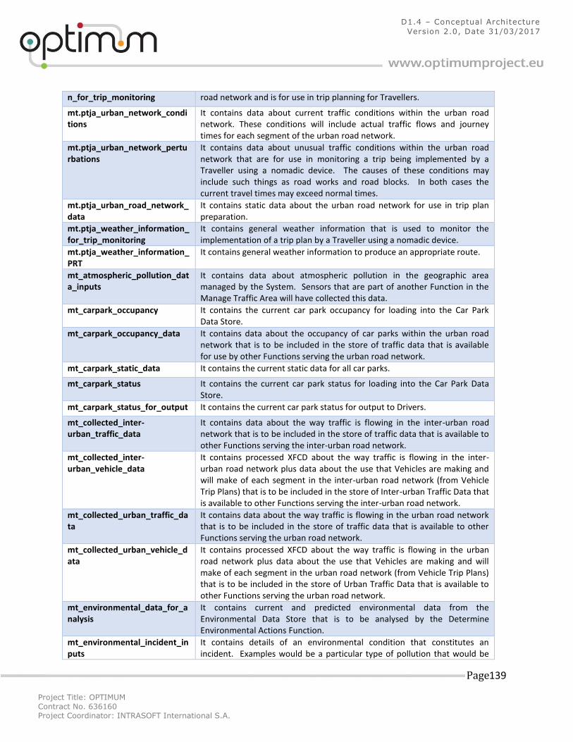
Project Title: OPTIMUM
Contract No. 636160 Project Coordinator: INTRASOFT International S.A.
Page 139
D1.4 – Conceptual Architecture
Version 2.0, Date 31/03/2017
n_for_trip_monitoring road network and is for use in trip planning for Travellers.
mt.ptja_urban_network_conditions
It contains data about current traffic conditions within the urban road network. These conditions will include actual traffic flows and journey times for each segment of the urban road network.
mt.ptja_urban_network_perturbations
It contains data about unusual traffic conditions within the urban road network that are for use in monitoring a trip being implemented by a Traveller using a nomadic device. The causes of these conditions may include such things as road works and road blocks. In both cases the current travel times may exceed normal times.
mt.ptja_urban_road_network_data
It contains static data about the urban road network for use in trip plan preparation.
mt.ptja_weather_information_for_trip_monitoring
It contains general weather information that is used to monitor the implementation of a trip plan by a Traveller using a nomadic device.
mt.ptja_weather_information_PRT
It contains general weather information to produce an appropriate route.
mt_atmospheric_pollution_data_inputs
It contains data about atmospheric pollution in the geographic area managed by the System. Sensors that are part of another Function in the Manage Traffic Area will have collected this data.
mt_carpark_occupancy It contains the current car park occupancy for loading into the Car Park Data Store.
mt_carpark_occupancy_data It contains data about the occupancy of car parks within the urban road network that is to be included in the store of traffic data that is available for use by other Functions serving the urban road network.
mt_carpark_static_data It contains the current static data for all car parks.
mt_carpark_status It contains the current car park status for loading into the Car Park Data Store.
mt_carpark_status_for_output It contains the current car park status for output to Drivers.
mt_collected_inter-urban_traffic_data
It contains data about the way traffic is flowing in the inter-urban road network that is to be included in the store of traffic data that is available to other Functions serving the inter-urban road network.
mt_collected_inter-urban_vehicle_data
It contains processed XFCD about the way traffic is flowing in the inter-urban road network plus data about the use that Vehicles are making and will make of each segment in the inter-urban road network (from Vehicle Trip Plans) that is to be included in the store of Inter-urban Traffic Data that is available to other Functions serving the inter-urban road network.
mt_collected_urban_traffic_data
It contains data about the way traffic is flowing in the urban road network that is to be included in the store of traffic data that is available to other Functions serving the urban road network.
mt_collected_urban_vehicle_data
It contains processed XFCD about the way traffic is flowing in the urban road network plus data about the use that Vehicles are making and will make of each segment in the urban road network (from Vehicle Trip Plans) that is to be included in the store of Urban Traffic Data that is available to other Functions serving the urban road network.
mt_environmental_data_for_analysis
It contains current and predicted environmental data from the Environmental Data Store that is to be analysed by the Determine Environmental Actions Function.
mt_environmental_incident_inputs
It contains details of an environmental condition that constitutes an incident. Examples would be a particular type of pollution that would be
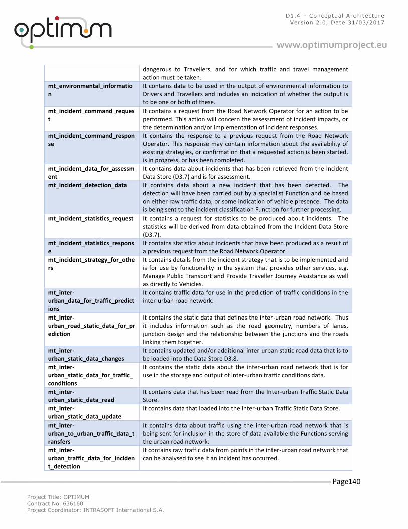
Project Title: OPTIMUM
Contract No. 636160 Project Coordinator: INTRASOFT International S.A.
Page 140
D1.4 – Conceptual Architecture
Version 2.0, Date 31/03/2017
dangerous to Travellers, and for which traffic and travel management action must be taken.
mt_environmental_information
It contains data to be used in the output of environmental information to Drivers and Travellers and includes an indication of whether the output is to be one or both of these.
mt_incident_command_request
It contains a request from the Road Network Operator for an action to be performed. This action will concern the assessment of incident impacts, or the determination and/or implementation of incident responses.
mt_incident_command_response
It contains the response to a previous request from the Road Network Operator. This response may contain information about the availability of existing strategies, or confirmation that a requested action is been started, is in progress, or has been completed.
mt_incident_data_for_assessment
It contains data about incidents that has been retrieved from the Incident Data Store (D3.7) and is for assessment.
mt_incident_detection_data It contains data about a new incident that has been detected. The detection will have been carried out by a specialist Function and be based on either raw traffic data, or some indication of vehicle presence. The data is being sent to the incident classification Function for further processing.
mt_incident_statistics_request It contains a request for statistics to be produced about incidents. The statistics will be derived from data obtained from the Incident Data Store (D3.7).
mt_incident_statistics_response
It contains statistics about incidents that have been produced as a result of a previous request from the Road Network Operator.
mt_incident_strategy_for_others
It contains details from the incident strategy that is to be implemented and is for use by functionality in the system that provides other services, e.g. Manage Public Transport and Provide Traveller Journey Assistance as well as directly to Vehicles.
mt_inter-urban_data_for_traffic_predictions
It contains traffic data for use in the prediction of traffic conditions in the inter-urban road network.
mt_inter-urban_road_static_data_for_prediction
It contains the static data that defines the inter-urban road network. Thus it includes information such as the road geometry, numbers of lanes, junction design and the relationship between the junctions and the roads linking them together.
mt_inter-urban_static_data_changes
It contains updated and/or additional inter-urban static road data that is to be loaded into the Data Store D3.8.
mt_inter-urban_static_data_for_traffic_conditions
It contains the static data about the inter-urban road network that is for use in the storage and output of inter-urban traffic conditions data.
mt_inter-urban_static_data_read
It contains data that has been read from the Inter-urban Traffic Static Data Store.
mt_inter-urban_static_data_update
It contains data that loaded into the Inter-urban Traffic Static Data Store.
mt_inter-urban_to_urban_traffic_data_transfers
It contains data about traffic using the inter-urban road network that is being sent for inclusion in the store of data available the Functions serving the urban road network.
mt_inter-urban_traffic_data_for_incident_detection
It contains raw traffic data from points in the inter-urban road network that can be analysed to see if an incident has occurred.
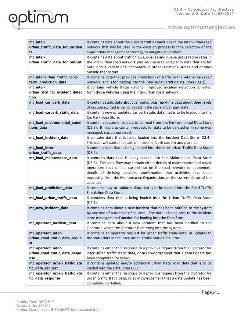
Project Title: OPTIMUM
Contract No. 636160 Project Coordinator: INTRASOFT International S.A.
Page 141
D1.4 – Conceptual Architecture
Version 2.0, Date 31/03/2017
mt_inter-urban_traffic_data_for_incidents
It contains data about the current traffic conditions in the inter-urban road network that will be used in the decision process for the selection of the appropriate management strategy to mitigate an incident.
mt_inter-urban_traffic_data_for_output
It contains data about traffic flows, queues and queue propagation rates in the inter-urban road network plus service area occupancy data that are for output to a variety of functionality in other Functional Areas and entities outside the System.
mt_inter-urban_traffic_long-term_prediction_data
It contains data that provides predictions of traffic in the inter-urban road network, and is for loading into the Inter-urban Traffic Data Store (D3.2).
mt_inter-urban_xfcd_for_incident_detection
It contains vehicle status data for improved incident detection collected from those Vehicles using the inter-urban road network.
mt_load_car_park_data It contains static data about car parks, plus real-time data about their levels of occupancy that is being loaded in the store of car park data.
mt_load_carpark_static_data It contains new or updated car park static data that is to be loaded into the Car Park Data Store.
mt_load_environmental_conditions_data
It contains requests for data to be read from the Environmental Data Store (D3.3). It may also contain requests for data to be deleted or in some way managed, e.g. compressed.
mt_load_incident_data It contains data that is to be loaded into the Incident Data Store (D3.4). This data will contain details of incidents, both current and planned.
mt_load_inter-urban_traffic_data
It contains data that is being loaded into the Inter-urban Traffic Data Store (D3.2).
mt_load_maintenance_data It contains data that is being loaded into the Maintenance Data Store (D3.6). This data flow may contain either details of maintenance and repair operations that can be carried out on the road network or equipment, details of de-icing activities, confirmation that activities have been requested from the Maintenance Organisation, or the current status of the activities.
mt_load_prediction_data It contains new or updated data that is to be loaded into the Road Traffic Simulation Data Store.
mt_load_urban_traffic_data It contains data that is being loaded into the Urban Traffic Data Store (D3.1).
mt_new_incident_data It contains data about a new incident that has been notified to the system by any one of a number of sources. The data is being sent to the incident store management Function for loading into the Data Store.
mt_operator_incident_data It contains data about a new incident that has been notified to the Operator, which the Operator is entering into the system.
mt_operator_inter-urban_road_static_data_request
It contains an operator request for urban traffic static data, or updates to the static data in the Inter-urban Traffic Static Data Store.
mt_operator_inter-urban_road_static_data_response
It contains either the response to a previous request from the Operator for inter-urban traffic static data, or acknowledgement that a data update has been completed (or failed).
mt_operator_urban_traffic_static_data_request
It contains updated and/or additional urban static road data that is to be loaded into the Data Store D3.7.
mt_operator_urban_traffic_static_data_response
It contains either the response to a previous request from the Operator for urban traffic static data, or acknowledgement that a data update has been completed (or failed).
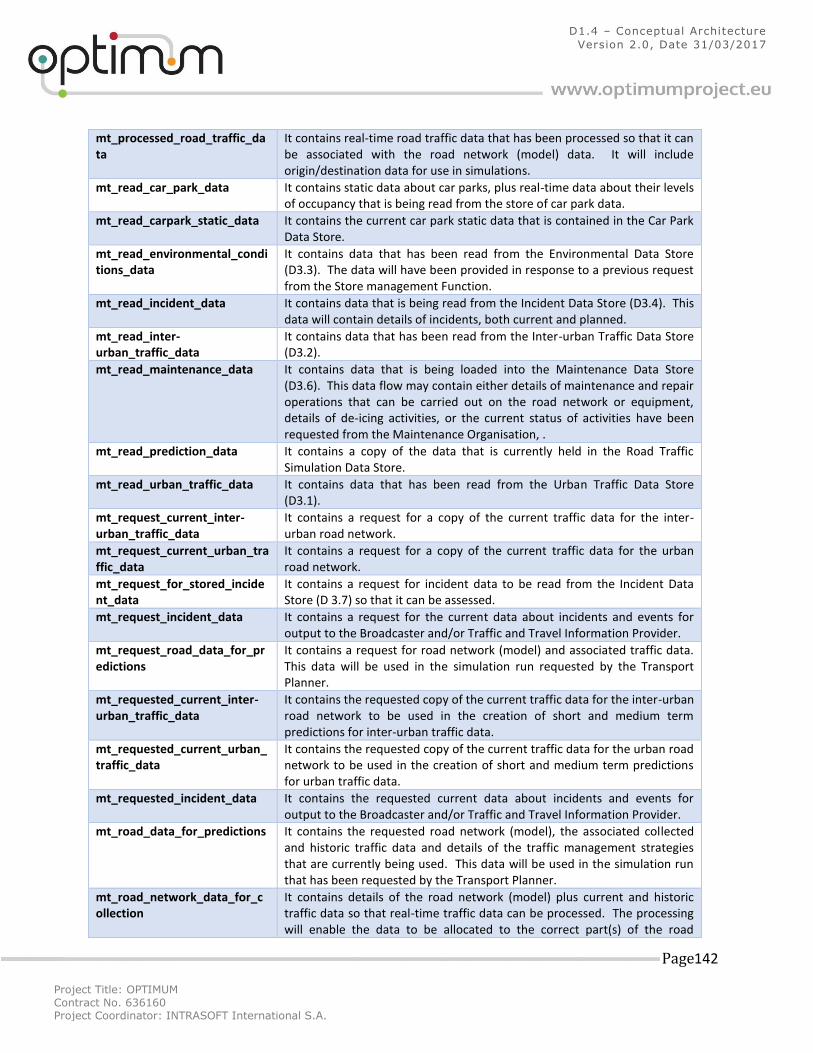
Project Title: OPTIMUM
Contract No. 636160 Project Coordinator: INTRASOFT International S.A.
Page 142
D1.4 – Conceptual Architecture
Version 2.0, Date 31/03/2017
mt_processed_road_traffic_data
It contains real-time road traffic data that has been processed so that it can be associated with the road network (model) data. It will include origin/destination data for use in simulations.
mt_read_car_park_data It contains static data about car parks, plus real-time data about their levels of occupancy that is being read from the store of car park data.
mt_read_carpark_static_data It contains the current car park static data that is contained in the Car Park Data Store.
mt_read_environmental_conditions_data
It contains data that has been read from the Environmental Data Store (D3.3). The data will have been provided in response to a previous request from the Store management Function.
mt_read_incident_data It contains data that is being read from the Incident Data Store (D3.4). This data will contain details of incidents, both current and planned.
mt_read_inter-urban_traffic_data
It contains data that has been read from the Inter-urban Traffic Data Store (D3.2).
mt_read_maintenance_data It contains data that is being loaded into the Maintenance Data Store (D3.6). This data flow may contain either details of maintenance and repair operations that can be carried out on the road network or equipment, details of de-icing activities, or the current status of activities have been requested from the Maintenance Organisation, .
mt_read_prediction_data It contains a copy of the data that is currently held in the Road Traffic Simulation Data Store.
mt_read_urban_traffic_data It contains data that has been read from the Urban Traffic Data Store (D3.1).
mt_request_current_inter-urban_traffic_data
It contains a request for a copy of the current traffic data for the inter-urban road network.
mt_request_current_urban_traffic_data
It contains a request for a copy of the current traffic data for the urban road network.
mt_request_for_stored_incident_data
It contains a request for incident data to be read from the Incident Data Store (D 3.7) so that it can be assessed.
mt_request_incident_data It contains a request for the current data about incidents and events for output to the Broadcaster and/or Traffic and Travel Information Provider.
mt_request_road_data_for_predictions
It contains a request for road network (model) and associated traffic data. This data will be used in the simulation run requested by the Transport Planner.
mt_requested_current_inter-urban_traffic_data
It contains the requested copy of the current traffic data for the inter-urban road network to be used in the creation of short and medium term predictions for inter-urban traffic data.
mt_requested_current_urban_traffic_data
It contains the requested copy of the current traffic data for the urban road network to be used in the creation of short and medium term predictions for urban traffic data.
mt_requested_incident_data It contains the requested current data about incidents and events for output to the Broadcaster and/or Traffic and Travel Information Provider.
mt_road_data_for_predictions It contains the requested road network (model), the associated collected and historic traffic data and details of the traffic management strategies that are currently being used. This data will be used in the simulation run that has been requested by the Transport Planner.
mt_road_network_data_for_collection
It contains details of the road network (model) plus current and historic traffic data so that real-time traffic data can be processed. The processing will enable the data to be allocated to the correct part(s) of the road
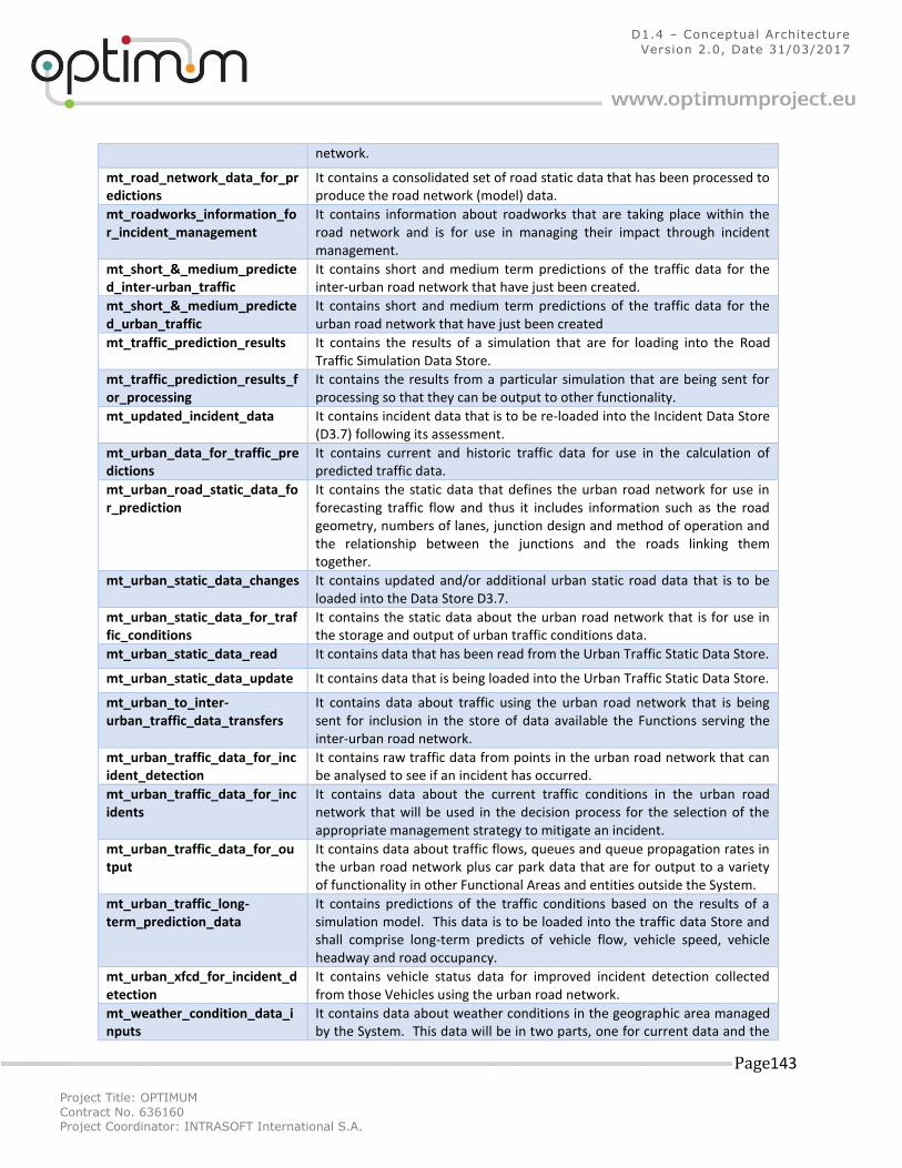
Project Title: OPTIMUM
Contract No. 636160 Project Coordinator: INTRASOFT International S.A.
Page 143
D1.4 – Conceptual Architecture
Version 2.0, Date 31/03/2017
network.
mt_road_network_data_for_predictions
It contains a consolidated set of road static data that has been processed to produce the road network (model) data.
mt_roadworks_information_for_incident_management
It contains information about roadworks that are taking place within the road network and is for use in managing their impact through incident management.
mt_short_&_medium_predicted_inter-urban_traffic
It contains short and medium term predictions of the traffic data for the inter-urban road network that have just been created.
mt_short_&_medium_predicted_urban_traffic
It contains short and medium term predictions of the traffic data for the urban road network that have just been created
mt_traffic_prediction_results It contains the results of a simulation that are for loading into the Road Traffic Simulation Data Store.
mt_traffic_prediction_results_for_processing
It contains the results from a particular simulation that are being sent for processing so that they can be output to other functionality.
mt_updated_incident_data It contains incident data that is to be re-loaded into the Incident Data Store (D3.7) following its assessment.
mt_urban_data_for_traffic_predictions
It contains current and historic traffic data for use in the calculation of predicted traffic data.
mt_urban_road_static_data_for_prediction
It contains the static data that defines the urban road network for use in forecasting traffic flow and thus it includes information such as the road geometry, numbers of lanes, junction design and method of operation and the relationship between the junctions and the roads linking them together.
mt_urban_static_data_changes It contains updated and/or additional urban static road data that is to be loaded into the Data Store D3.7.
mt_urban_static_data_for_traffic_conditions
It contains the static data about the urban road network that is for use in the storage and output of urban traffic conditions data.
mt_urban_static_data_read It contains data that has been read from the Urban Traffic Static Data Store.
mt_urban_static_data_update It contains data that is being loaded into the Urban Traffic Static Data Store.
mt_urban_to_inter-urban_traffic_data_transfers
It contains data about traffic using the urban road network that is being sent for inclusion in the store of data available the Functions serving the inter-urban road network.
mt_urban_traffic_data_for_incident_detection
It contains raw traffic data from points in the urban road network that can be analysed to see if an incident has occurred.
mt_urban_traffic_data_for_incidents
It contains data about the current traffic conditions in the urban road network that will be used in the decision process for the selection of the appropriate management strategy to mitigate an incident.
mt_urban_traffic_data_for_output
It contains data about traffic flows, queues and queue propagation rates in the urban road network plus car park data that are for output to a variety of functionality in other Functional Areas and entities outside the System.
mt_urban_traffic_long-term_prediction_data
It contains predictions of the traffic conditions based on the results of a simulation model. This data is to be loaded into the traffic data Store and shall comprise long-term predicts of vehicle flow, vehicle speed, vehicle headway and road occupancy.
mt_urban_xfcd_for_incident_detection
It contains vehicle status data for improved incident detection collected from those Vehicles using the urban road network.
mt_weather_condition_data_inputs
It contains data about weather conditions in the geographic area managed by the System. This data will be in two parts, one for current data and the
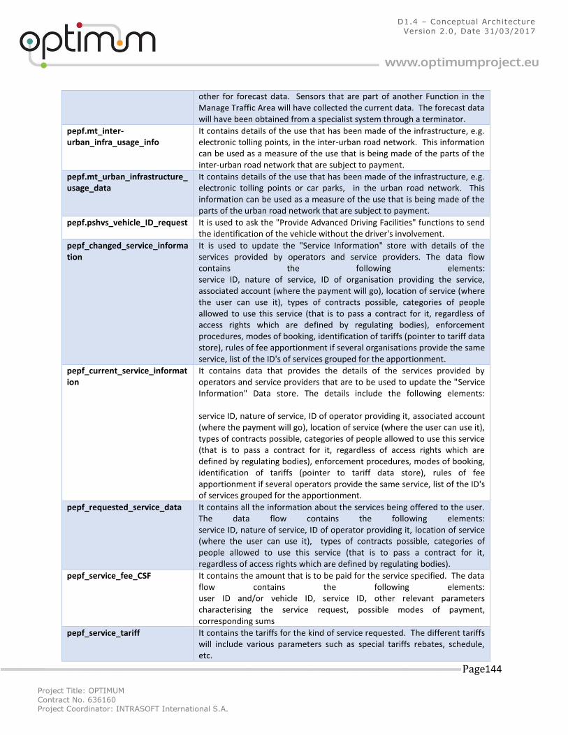
Project Title: OPTIMUM
Contract No. 636160 Project Coordinator: INTRASOFT International S.A.
Page 144
D1.4 – Conceptual Architecture
Version 2.0, Date 31/03/2017
other for forecast data. Sensors that are part of another Function in the Manage Traffic Area will have collected the current data. The forecast data will have been obtained from a specialist system through a terminator.
pepf.mt_inter-urban_infra_usage_info
It contains details of the use that has been made of the infrastructure, e.g. electronic tolling points, in the inter-urban road network. This information can be used as a measure of the use that is being made of the parts of the inter-urban road network that are subject to payment.
pepf.mt_urban_infrastructure_usage_data
It contains details of the use that has been made of the infrastructure, e.g. electronic tolling points or car parks, in the urban road network. This information can be used as a measure of the use that is being made of the parts of the urban road network that are subject to payment.
pepf.pshvs_vehicle_ID_request It is used to ask the "Provide Advanced Driving Facilities" functions to send the identification of the vehicle without the driver's involvement.
pepf_changed_service_information
It is used to update the "Service Information" store with details of the services provided by operators and service providers. The data flow contains the following elements: service ID, nature of service, ID of organisation providing the service, associated account (where the payment will go), location of service (where the user can use it), types of contracts possible, categories of people allowed to use this service (that is to pass a contract for it, regardless of access rights which are defined by regulating bodies), enforcement procedures, modes of booking, identification of tariffs (pointer to tariff data store), rules of fee apportionment if several organisations provide the same service, list of the ID's of services grouped for the apportionment.
pepf_current_service_information
It contains data that provides the details of the services provided by operators and service providers that are to be used to update the "Service Information" Data store. The details include the following elements: service ID, nature of service, ID of operator providing it, associated account (where the payment will go), location of service (where the user can use it), types of contracts possible, categories of people allowed to use this service (that is to pass a contract for it, regardless of access rights which are defined by regulating bodies), enforcement procedures, modes of booking, identification of tariffs (pointer to tariff data store), rules of fee apportionment if several operators provide the same service, list of the ID's of services grouped for the apportionment.
pepf_requested_service_data It contains all the information about the services being offered to the user. The data flow contains the following elements: service ID, nature of service, ID of operator providing it, location of service (where the user can use it), types of contracts possible, categories of people allowed to use this service (that is to pass a contract for it, regardless of access rights which are defined by regulating bodies).
pepf_service_fee_CSF It contains the amount that is to be paid for the service specified. The data flow contains the following elements: user ID and/or vehicle ID, service ID, other relevant parameters characterising the service request, possible modes of payment, corresponding sums
pepf_service_tariff It contains the tariffs for the kind of service requested. The different tariffs will include various parameters such as special tariffs rebates, schedule, etc.
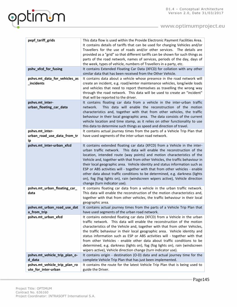
Project Title: OPTIMUM
Contract No. 636160 Project Coordinator: INTRASOFT International S.A.
Page 145
D1.4 – Conceptual Architecture
Version 2.0, Date 31/03/2017
pepf_tariff_grids This data flow is used within the Provide Electronic Payment Facilities Area. It contains details of tariffs that can be used for charging Vehicles and/or Travellers for the use of roads and/or other services. The details are provided as a "grid" so that different tariffs can be shown for such things as parts of the road network, names of services, periods of the day, days of the week, types of vehicle, numbers of Travellers in a party, etc.
pshv_xfcd_for_fusing It contains Extended Floating Car Data (XFCD) for collation with any other similar data that has been received from the Other Vehicle.
pshvs.mt_data_for_vehicles_as_incidents
It contains data about a vehicle whose presence in the road network will create an incident, e.g. road/winter maintenance vehicles, long/wide loads and vehicles that need to report themselves as travelling the wrong way through the road network. This data will be used to create an "incident" that will be reported to the driver.
pshvs.mt_inter-urban_floating_car_data
It contains floating car data from a vehicle in the inter-urban traffic network. This data will enable the reconstruction of the motion characteristics and, together with that from other vehicles, the traffic behaviour in their local geographic area. The data consists of the current vehicle location and time stamp, as it relies on other functionality to use this data to determine such things as speed and direction of travel.
pshvs.mt_inter-urban_road_use_data_from_trip
It contains actual journey times from the parts of a Vehicle Trip Plan that have used segments of the inter-urban road network.
pshvs.mt_inter-urban_xfcd It contains extended floating car data (XFCD) from a Vehicle in the inter-urban traffic network. This data will enable the reconstruction of the location, intended route (way points) and motion characteristics of the Vehicle and, together with that from other Vehicles, the traffic behaviour in their local geographic area. Vehicle identity and status information such as ESP or ABS activities will - together with that from other vehicles - enable other data about traffic conditions to be determined, e.g. darkness (lights on), fog (fog lights on), rain (windscreen wipers active), Vehicle direction change (turn indicator use).
pshvs.mt_urban_floating_car_data
It contains floating car data from a vehicle in the urban traffic network. This data will enable the reconstruction of the motion characteristics and, together with that from other vehicles, the traffic behaviour in their local geographic area.
pshvs.mt_urban_road_use_data_from_trip
It contains actual journey times from the parts of a Vehicle Trip Plan that have used segments of the urban road network.
pshvs.mt_urban_xfcd It contains extended floating car data (XFCD) from a Vehicle in the urban traffic network. This data will enable the reconstruction of the motion characteristics of the Vehicle and, together with that from other Vehicles, the traffic behaviour in their local geographic area. Vehicle identity and status information such as ESP or ABS activities will - together with that from other Vehicles - enable other data about traffic conditions to be determined, e.g. darkness (lights on), fog (fog lights on), rain (windscreen wipers active), Vehicle direction change (turn indicator use).
pshvs.mt_vehicle_trip_plan_o-d_data
It contains origin - destination (O-D) data and actual journey time for the complete Vehicle Trip Plan that has just been implemented.
pshvs.mt_vehicle_trip_plan_route_for_inter-urban
It contains the route for the latest Vehicle Trip Plan that is being used to guide the Driver.
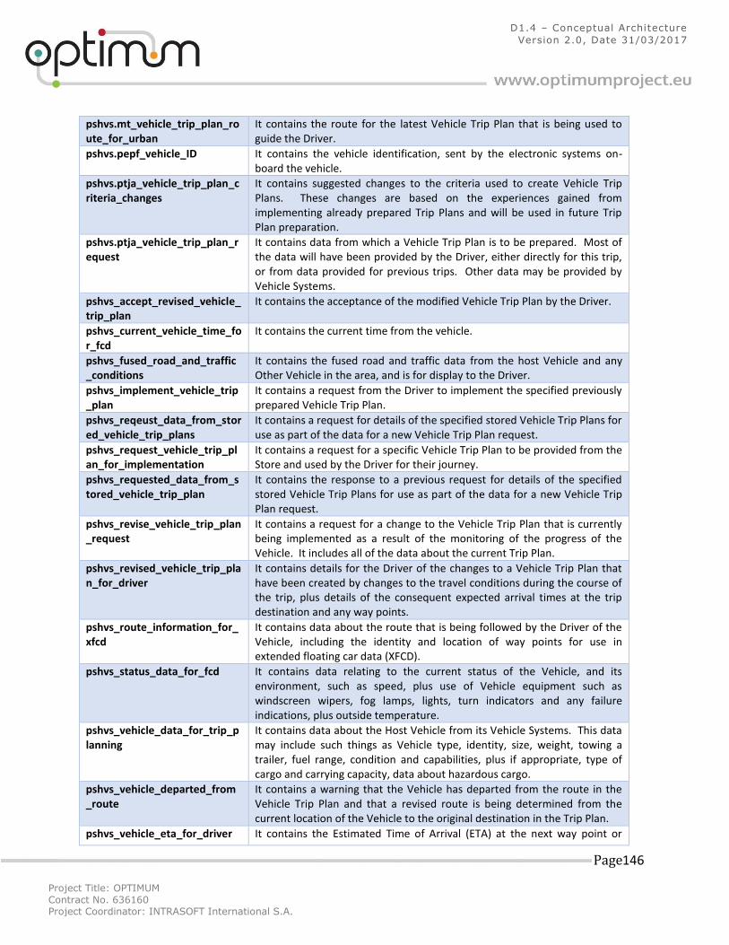
Project Title: OPTIMUM
Contract No. 636160 Project Coordinator: INTRASOFT International S.A.
Page 146
D1.4 – Conceptual Architecture
Version 2.0, Date 31/03/2017
pshvs.mt_vehicle_trip_plan_route_for_urban
It contains the route for the latest Vehicle Trip Plan that is being used to guide the Driver.
pshvs.pepf_vehicle_ID It contains the vehicle identification, sent by the electronic systems on-board the vehicle.
pshvs.ptja_vehicle_trip_plan_criteria_changes
It contains suggested changes to the criteria used to create Vehicle Trip Plans. These changes are based on the experiences gained from implementing already prepared Trip Plans and will be used in future Trip Plan preparation.
pshvs.ptja_vehicle_trip_plan_request
It contains data from which a Vehicle Trip Plan is to be prepared. Most of the data will have been provided by the Driver, either directly for this trip, or from data provided for previous trips. Other data may be provided by Vehicle Systems.
pshvs_accept_revised_vehicle_trip_plan
It contains the acceptance of the modified Vehicle Trip Plan by the Driver.
pshvs_current_vehicle_time_for_fcd
It contains the current time from the vehicle.
pshvs_fused_road_and_traffic_conditions
It contains the fused road and traffic data from the host Vehicle and any Other Vehicle in the area, and is for display to the Driver.
pshvs_implement_vehicle_trip_plan
It contains a request from the Driver to implement the specified previously prepared Vehicle Trip Plan.
pshvs_reqeust_data_from_stored_vehicle_trip_plans
It contains a request for details of the specified stored Vehicle Trip Plans for use as part of the data for a new Vehicle Trip Plan request.
pshvs_request_vehicle_trip_plan_for_implementation
It contains a request for a specific Vehicle Trip Plan to be provided from the Store and used by the Driver for their journey.
pshvs_requested_data_from_stored_vehicle_trip_plan
It contains the response to a previous request for details of the specified stored Vehicle Trip Plans for use as part of the data for a new Vehicle Trip Plan request.
pshvs_revise_vehicle_trip_plan_request
It contains a request for a change to the Vehicle Trip Plan that is currently being implemented as a result of the monitoring of the progress of the Vehicle. It includes all of the data about the current Trip Plan.
pshvs_revised_vehicle_trip_plan_for_driver
It contains details for the Driver of the changes to a Vehicle Trip Plan that have been created by changes to the travel conditions during the course of the trip, plus details of the consequent expected arrival times at the trip destination and any way points.
pshvs_route_information_for_xfcd
It contains data about the route that is being followed by the Driver of the Vehicle, including the identity and location of way points for use in extended floating car data (XFCD).
pshvs_status_data_for_fcd It contains data relating to the current status of the Vehicle, and its environment, such as speed, plus use of Vehicle equipment such as windscreen wipers, fog lamps, lights, turn indicators and any failure indications, plus outside temperature.
pshvs_vehicle_data_for_trip_planning
It contains data about the Host Vehicle from its Vehicle Systems. This data may include such things as Vehicle type, identity, size, weight, towing a trailer, fuel range, condition and capabilities, plus if appropriate, type of cargo and carrying capacity, data about hazardous cargo.
pshvs_vehicle_departed_from_route
It contains a warning that the Vehicle has departed from the route in the Vehicle Trip Plan and that a revised route is being determined from the current location of the Vehicle to the original destination in the Trip Plan.
pshvs_vehicle_eta_for_driver It contains the Estimated Time of Arrival (ETA) at the next way point or
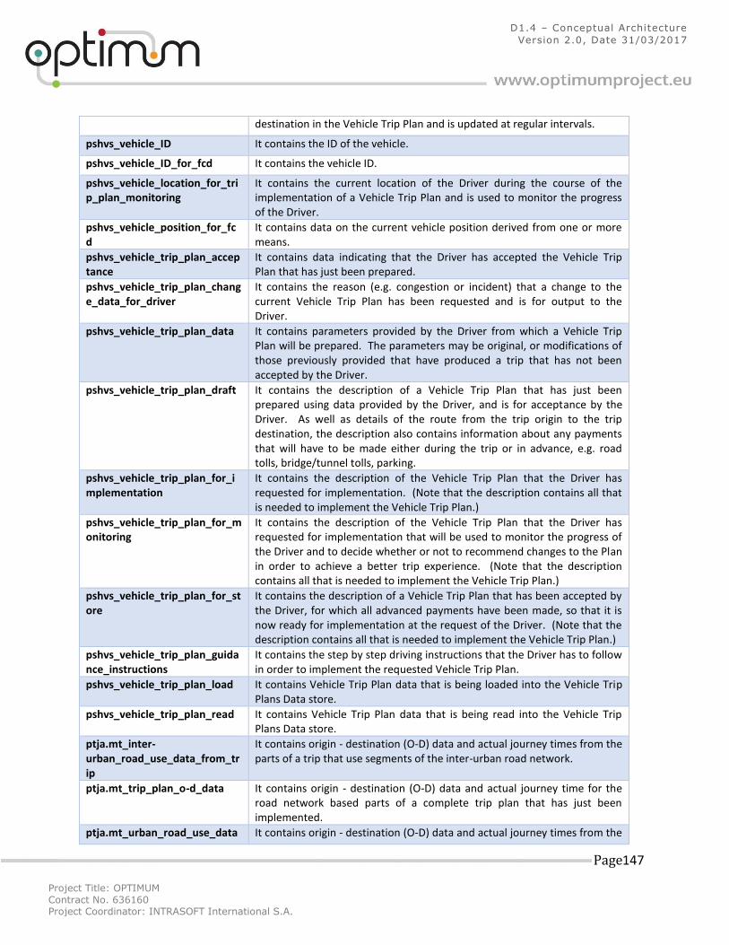
Project Title: OPTIMUM
Contract No. 636160 Project Coordinator: INTRASOFT International S.A.
Page 147
D1.4 – Conceptual Architecture
Version 2.0, Date 31/03/2017
destination in the Vehicle Trip Plan and is updated at regular intervals.
pshvs_vehicle_ID It contains the ID of the vehicle.
pshvs_vehicle_ID_for_fcd It contains the vehicle ID.
pshvs_vehicle_location_for_trip_plan_monitoring
It contains the current location of the Driver during the course of the implementation of a Vehicle Trip Plan and is used to monitor the progress of the Driver.
pshvs_vehicle_position_for_fcd
It contains data on the current vehicle position derived from one or more means.
pshvs_vehicle_trip_plan_acceptance
It contains data indicating that the Driver has accepted the Vehicle Trip Plan that has just been prepared.
pshvs_vehicle_trip_plan_change_data_for_driver
It contains the reason (e.g. congestion or incident) that a change to the current Vehicle Trip Plan has been requested and is for output to the Driver.
pshvs_vehicle_trip_plan_data It contains parameters provided by the Driver from which a Vehicle Trip Plan will be prepared. The parameters may be original, or modifications of those previously provided that have produced a trip that has not been accepted by the Driver.
pshvs_vehicle_trip_plan_draft It contains the description of a Vehicle Trip Plan that has just been prepared using data provided by the Driver, and is for acceptance by the Driver. As well as details of the route from the trip origin to the trip destination, the description also contains information about any payments that will have to be made either during the trip or in advance, e.g. road tolls, bridge/tunnel tolls, parking.
pshvs_vehicle_trip_plan_for_implementation
It contains the description of the Vehicle Trip Plan that the Driver has requested for implementation. (Note that the description contains all that is needed to implement the Vehicle Trip Plan.)
pshvs_vehicle_trip_plan_for_monitoring
It contains the description of the Vehicle Trip Plan that the Driver has requested for implementation that will be used to monitor the progress of the Driver and to decide whether or not to recommend changes to the Plan in order to achieve a better trip experience. (Note that the description contains all that is needed to implement the Vehicle Trip Plan.)
pshvs_vehicle_trip_plan_for_store
It contains the description of a Vehicle Trip Plan that has been accepted by the Driver, for which all advanced payments have been made, so that it is now ready for implementation at the request of the Driver. (Note that the description contains all that is needed to implement the Vehicle Trip Plan.)
pshvs_vehicle_trip_plan_guidance_instructions
It contains the step by step driving instructions that the Driver has to follow in order to implement the requested Vehicle Trip Plan.
pshvs_vehicle_trip_plan_load It contains Vehicle Trip Plan data that is being loaded into the Vehicle Trip Plans Data store.
pshvs_vehicle_trip_plan_read It contains Vehicle Trip Plan data that is being read into the Vehicle Trip Plans Data store.
ptja.mt_inter-urban_road_use_data_from_trip
It contains origin - destination (O-D) data and actual journey times from the parts of a trip that use segments of the inter-urban road network.
ptja.mt_trip_plan_o-d_data It contains origin - destination (O-D) data and actual journey time for the road network based parts of a complete trip plan that has just been implemented.
ptja.mt_urban_road_use_data It contains origin - destination (O-D) data and actual journey times from the
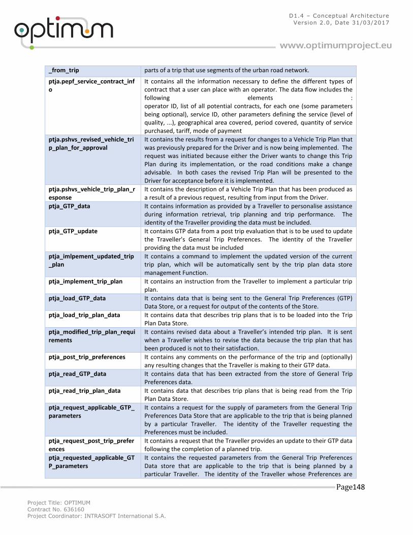
Project Title: OPTIMUM
Contract No. 636160 Project Coordinator: INTRASOFT International S.A.
Page 148
D1.4 – Conceptual Architecture
Version 2.0, Date 31/03/2017
_from_trip parts of a trip that use segments of the urban road network.
ptja.pepf_service_contract_info
It contains all the information necessary to define the different types of contract that a user can place with an operator. The data flow includes the following elements : operator ID, list of all potential contracts, for each one (some parameters being optional), service ID, other parameters defining the service (level of quality, ...), geographical area covered, period covered, quantity of service purchased, tariff, mode of payment
ptja.pshvs_revised_vehicle_trip_plan_for_approval
It contains the results from a request for changes to a Vehicle Trip Plan that was previously prepared for the Driver and is now being implemented. The request was initiated because either the Driver wants to change this Trip Plan during its implementation, or the road conditions make a change advisable. In both cases the revised Trip Plan will be presented to the Driver for acceptance before it is implemented.
ptja.pshvs_vehicle_trip_plan_response
It contains the description of a Vehicle Trip Plan that has been produced as a result of a previous request, resulting from input from the Driver.
ptja_GTP_data It contains information as provided by a Traveller to personalise assistance during information retrieval, trip planning and trip performance. The identity of the Traveller providing the data must be included.
ptja_GTP_update It contains GTP data from a post trip evaluation that is to be used to update the Traveller's General Trip Preferences. The identity of the Traveller providing the data must be included
ptja_imlpement_updated_trip_plan
It contains a command to implement the updated version of the current trip plan, which will be automatically sent by the trip plan data store management Function.
ptja_implement_trip_plan It contains an instruction from the Traveller to implement a particular trip plan.
ptja_load_GTP_data It contains data that is being sent to the General Trip Preferences (GTP) Data Store, or a request for output of the contents of the Store.
ptja_load_trip_plan_data It contains data that describes trip plans that is to be loaded into the Trip Plan Data Store.
ptja_modified_trip_plan_requirements
It contains revised data about a Traveller’s intended trip plan. It is sent when a Traveller wishes to revise the data because the trip plan that has been produced is not to their satisfaction.
ptja_post_trip_preferences It contains any comments on the performance of the trip and (optionally) any resulting changes that the Traveller is making to their GTP data.
ptja_read_GTP_data It contains data that has been extracted from the store of General Trip Preferences data.
ptja_read_trip_plan_data It contains data that describes trip plans that is being read from the Trip Plan Data Store.
ptja_request_applicable_GTP_parameters
It contains a request for the supply of parameters from the General Trip Preferences Data Store that are applicable to the trip that is being planned by a particular Traveller. The identity of the Traveller requesting the Preferences must be included.
ptja_request_post_trip_preferences
It contains a request that the Traveller provides an update to their GTP data following the completion of a planned trip.
ptja_requested_applicable_GTP_parameters
It contains the requested parameters from the General Trip Preferences Data store that are applicable to the trip that is being planned by a particular Traveller. The identity of the Traveller whose Preferences are
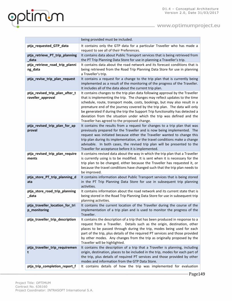
Project Title: OPTIMUM
Contract No. 636160 Project Coordinator: INTRASOFT International S.A.
Page 149
D1.4 – Conceptual Architecture
Version 2.0, Date 31/03/2017
being provided must be included.
ptja_requested_GTP_data It contains only the GTP data for a particular Traveller who has made a request to see all of their Preferences.
ptja_retrieve_PT_trip_planning_data
It contains data about Public Transport services that is being retrieved from the PT Trip Planning Data Store for use in planning a Traveller’s trip.
ptja_retrieve_road_trip_planning_data
It contains data about the road network and its forecast conditions that is being retrieved from the Road Trip Planning Data Store for use in planning a Traveller’s trip.
ptja_revise_trip_plan_request It contains a request for a change to the trip plan that is currently being implemented as a result of the monitoring of the progress of the Traveller. It includes all of the data about the current trip plan.
ptja_revised_trip_plan_after_traveller_approval
It contains changes to the trip plan data following approval by the Traveller that is implementing the trip. The changes may reflect updates to the time schedule, route, transport mode, costs, bookings, but may also result in a premature end of the journey covered by the trip plan. The data will only be generated if during the trip the Support Trip functionality has detected a deviation from the situation under which the trip was defined and the Traveller has agreed to the proposed change.
ptja_revised_trip_plan_for_approval
It contains the results from a request for changes to a trip plan that was previously prepared for the Traveller and is now being implemented. The request was initiated because either the Traveller wanted to change this trip plan during its implementation, or the travel conditions make a change advisable. In both cases, the revised trip plan will be presented to the Traveller for acceptance before it is implemented.
ptja_revised_trip_plan_requirements
It contains revised data about the way in which the trip plan that a Traveller is currently using is to be modified. It is sent when it is necessary for the trip plan to be changed, either because the Traveller has requested it, or because the travel conditions have changed such that the trip plan needs to be improved.
ptja_store_PT_trip_planning_data
It contains information about Public Transport services that is being stored in the PT Trip Planning Data Store for use in subsequent trip planning activities.
ptja_store_road_trip_planning_data
It contains information about the road network and its current state that is being stored in the Road Trip Planning Data Store for use in subsequent trip planning activities.
ptja_traveller_location_for_trip_monitoring
It contains the current location of the Traveller during the course of the implementation of a trip plan and is used to monitor the progress of the Traveller.
ptja_traveller_trip_description It contains the description of a trip that has been produced in response to a request from a Traveller. Details such as the origin, destination, other places to be passed through during the trip, modes being used for each part of the trip, plus details of the required PT services and those provided by other modes. Any changes from the trip as originally proposed by the Traveller will be highlighted.
ptja_traveller_trip_requirement
It contains the description of a trip that a Traveller is planning, including origin, destination, places to be included in the trip, modes for each part of the trip, plus details of required PT services and those provided by other modes and information from the GTP Data Store.
ptja_trip_completion_report_f It contains details of how the trip was implemented for evaluation
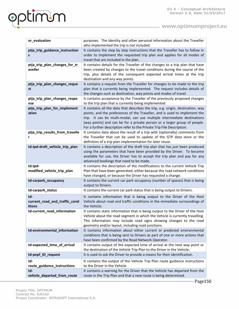
Project Title: OPTIMUM
Contract No. 636160 Project Coordinator: INTRASOFT International S.A.
Page 150
D1.4 – Conceptual Architecture
Version 2.0, Date 31/03/2017
or_evaluation purposes. The identity and other personal information about the Traveller who implemented the trip is not included.
ptja_trip_guidance_instructions
It contains the step by step instructions that the Traveller has to follow in order to implement the requested trip plan and applies for all modes of travel that are included in the plan.
ptja_trip_plan_changes_for_traveller
It contains details for the Traveller of the changes to a trip plan that have been created by changes to the travel conditions during the course of the trip, plus details of the consequent expected arrival times at the trip destination and any way points.
ptja_trip_plan_changes_request
It contains a request from the Traveller for changes to be made to the trip plan that is currently being implemented. The request includes details of the changes such as destination, way points and modes of travel.
ptja_trip_plan_changes_response
It contains acceptance by the Traveller of the previously proposed changes to the trip plan that is currently being implemented.
ptja_trip_plan_for_implementation
It contains all the data that describes the trip, e.g. origin, destination, way points, and the preferences of the Traveller, and is used to implement the trip. It can be multi-modal, can use multiple intermediate destinations (way points) and can be for a private person or a larger group of people. For a further description refer to the Private Trip File Description.
ptja_trip_results_from_traveller
It contains data about the result of a trip with (optionally) comments from the Traveller that can be used to update of the GTP data store or the definition of a trip plan implementation for later reuse.
td.tpd-draft_vehicle_trip_plan It contains a description of the draft trip plan that has just been produced using the parameters that have been provided by the Driver. To become available for use, the Driver has to accept the trip plan and pay for any advanced bookings that need to be made.
td.tpd-modified_vehicle_trip_plan
It contains the description of the modifications to the current Vehicle Trip Plan that have been generated, either because the road network conditions have changed, or because the Driver has requested a change.
td-carpark_occupancy It contains the current car park occupancy (number of spaces) that is being output to Drivers.
td-carpark_status It contains the current car park status that is being output to Drivers.
td-current_road_and_traffic_conditions
It contains information that is being output to the Driver of the Host Vehicle about road and traffic conditions in the immediate surroundings of the Vehicle.
td-current_road_information It contains static information that is being output to the Driver of the Host Vehicle about the road segment in which the Vehicle is currently travelling. This information may include road signs showing changes to the road geometry and/or layout, including road junctions.
td-environmental_information It contains information about either current or predicted environmental conditions that is being sent to Drivers as part of one or more actions that have been confirmed by the Road Network Operator.
td-expected_time_of_arrival It contains output of the expected time of arrival at the next way point or the destination of the Vehicle Trip Plan to the Driver in the Vehicle.
td-pepf_ID_request It is used to ask the Driver to provide a means for their identification.
td-route_guidance_instructions
It contains the output of the Vehicle Trip Plan route guidance instructions to the Driver in the Vehicle.
td-vehicle_departed_from_route
It contains a warning for the Driver that the Vehicle has departed from the route in the Trip Plan and that a new route is being determined.
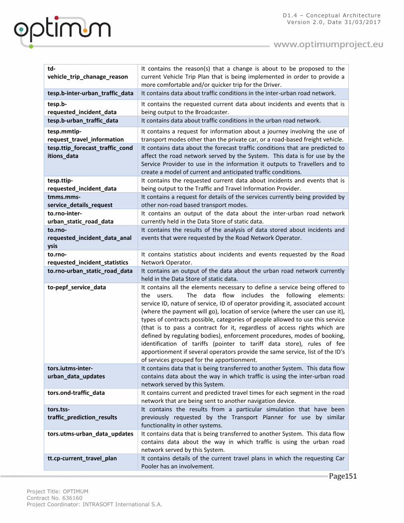
Project Title: OPTIMUM
Contract No. 636160 Project Coordinator: INTRASOFT International S.A.
Page 151
D1.4 – Conceptual Architecture
Version 2.0, Date 31/03/2017
td-vehicle_trip_chanage_reason
It contains the reason(s) that a change is about to be proposed to the current Vehicle Trip Plan that is being implemented in order to provide a more comfortable and/or quicker trip for the Driver.
tesp.b-inter-urban_traffic_data It contains data about traffic conditions in the inter-urban road network.
tesp.b-requested_incident_data
It contains the requested current data about incidents and events that is being output to the Broadcaster.
tesp.b-urban_traffic_data It contains data about traffic conditions in the urban road network.
tesp.mmtip-request_travel_information
It contains a request for information about a journey involving the use of transport modes other than the private car, or a road-based freight vehicle.
tesp.ttip_forecast_traffic_conditions_data
It contains data about the forecast traffic conditions that are predicted to affect the road network served by the System. This data is for use by the Service Provider to use in the information it outputs to Travellers and to create a model of current and anticipated traffic conditions.
tesp.ttip-requested_incident_data
It contains the requested current data about incidents and events that is being output to the Traffic and Travel Information Provider.
tmms.mms-service_details_request
It contains a request for details of the services currently being provided by other non-road based transport modes.
to.rno-inter-urban_static_road_data
It contains an output of the data about the inter-urban road network currently held in the Data Store of static data.
to.rno-requested_incident_data_analysis
It contains the results of the analysis of data stored about incidents and events that were requested by the Road Network Operator.
to.rno-requested_incident_statistics
It contains statistics about incidents and events requested by the Road Network Operator.
to.rno-urban_static_road_data It contains an output of the data about the urban road network currently held in the Data Store of static data.
to-pepf_service_data It contains all the elements necessary to define a service being offered to the users. The data flow includes the following elements: service ID, nature of service, ID of operator providing it, associated account (where the payment will go), location of service (where the user can use it), types of contracts possible, categories of people allowed to use this service (that is to pass a contract for it, regardless of access rights which are defined by regulating bodies), enforcement procedures, modes of booking, identification of tariffs (pointer to tariff data store), rules of fee apportionment if several operators provide the same service, list of the ID's of services grouped for the apportionment.
tors.iutms-inter-urban_data_updates
It contains data that is being transferred to another System. This data flow contains data about the way in which traffic is using the inter-urban road network served by this System.
tors.ond-traffic_data It contains current and predicted travel times for each segment in the road network that are being sent to another navigation device.
tors.tss-traffic_prediction_results
It contains the results from a particular simulation that have been previously requested by the Transport Planner for use by similar functionality in other systems.
tors.utms-urban_data_updates It contains data that is being transferred to another System. This data flow contains data about the way in which traffic is using the urban road network served by this System.
tt.cp-current_travel_plan It contains details of the current travel plans in which the requesting Car Pooler has an involvement.
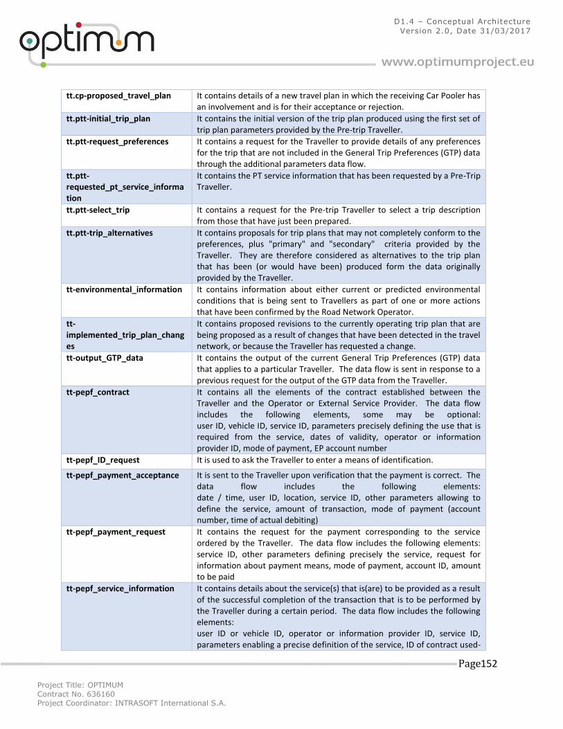
Project Title: OPTIMUM
Contract No. 636160 Project Coordinator: INTRASOFT International S.A.
Page 152
D1.4 – Conceptual Architecture
Version 2.0, Date 31/03/2017
tt.cp-proposed_travel_plan It contains details of a new travel plan in which the receiving Car Pooler has an involvement and is for their acceptance or rejection.
tt.ptt-initial_trip_plan It contains the initial version of the trip plan produced using the first set of trip plan parameters provided by the Pre-trip Traveller.
tt.ptt-request_preferences It contains a request for the Traveller to provide details of any preferences for the trip that are not included in the General Trip Preferences (GTP) data through the additional parameters data flow.
tt.ptt-requested_pt_service_information
It contains the PT service information that has been requested by a Pre-Trip Traveller.
tt.ptt-select_trip It contains a request for the Pre-trip Traveller to select a trip description from those that have just been prepared.
tt.ptt-trip_alternatives It contains proposals for trip plans that may not completely conform to the preferences, plus "primary" and "secondary" criteria provided by the Traveller. They are therefore considered as alternatives to the trip plan that has been (or would have been) produced form the data originally provided by the Traveller.
tt-environmental_information It contains information about either current or predicted environmental conditions that is being sent to Travellers as part of one or more actions that have been confirmed by the Road Network Operator.
tt-implemented_trip_plan_changes
It contains proposed revisions to the currently operating trip plan that are being proposed as a result of changes that have been detected in the travel network, or because the Traveller has requested a change.
tt-output_GTP_data It contains the output of the current General Trip Preferences (GTP) data that applies to a particular Traveller. The data flow is sent in response to a previous request for the output of the GTP data from the Traveller.
tt-pepf_contract It contains all the elements of the contract established between the Traveller and the Operator or External Service Provider. The data flow includes the following elements, some may be optional: user ID, vehicle ID, service ID, parameters precisely defining the use that is required from the service, dates of validity, operator or information provider ID, mode of payment, EP account number
tt-pepf_ID_request It is used to ask the Traveller to enter a means of identification.
tt-pepf_payment_acceptance It is sent to the Traveller upon verification that the payment is correct. The data flow includes the following elements: date / time, user ID, location, service ID, other parameters allowing to define the service, amount of transaction, mode of payment (account number, time of actual debiting)
tt-pepf_payment_request It contains the request for the payment corresponding to the service ordered by the Traveller. The data flow includes the following elements: service ID, other parameters defining precisely the service, request for information about payment means, mode of payment, account ID, amount to be paid
tt-pepf_service_information It contains details about the service(s) that is(are) to be provided as a result of the successful completion of the transaction that is to be performed by the Traveller during a certain period. The data flow includes the following elements: user ID or vehicle ID, operator or information provider ID, service ID, parameters enabling a precise definition of the service, ID of contract used-
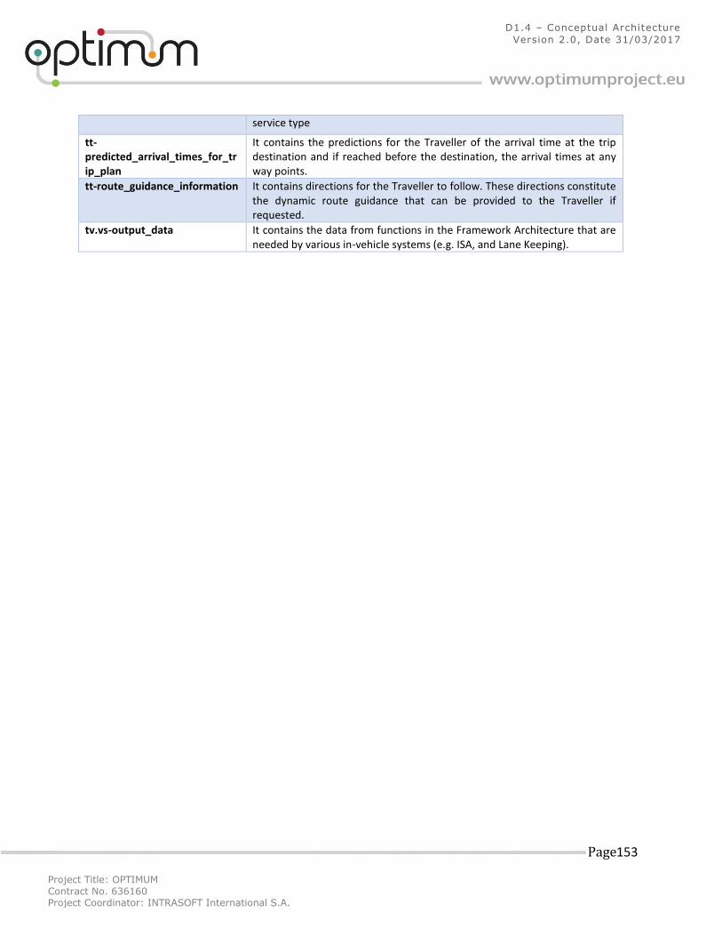
Project Title: OPTIMUM
Contract No. 636160 Project Coordinator: INTRASOFT International S.A.
Page 153
D1.4 – Conceptual Architecture
Version 2.0, Date 31/03/2017
service type
tt-predicted_arrival_times_for_trip_plan
It contains the predictions for the Traveller of the arrival time at the trip destination and if reached before the destination, the arrival times at any way points.
tt-route_guidance_information It contains directions for the Traveller to follow. These directions constitute the dynamic route guidance that can be provided to the Traveller if requested.
tv.vs-output_data It contains the data from functions in the Framework Architecture that are needed by various in-vehicle systems (e.g. ISA, and Lane Keeping).
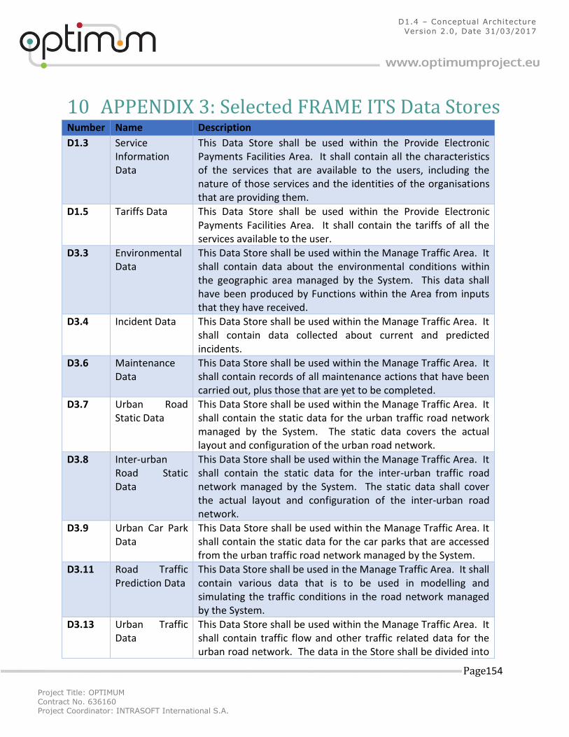
Project Title: OPTIMUM
Contract No. 636160 Project Coordinator: INTRASOFT International S.A.
Page 154
D1.4 – Conceptual Architecture
Version 2.0, Date 31/03/2017
10 APPENDIX 3: Selected FRAME ITS Data Stores Number Name Description
D1.3 Service Information Data
This Data Store shall be used within the Provide Electronic Payments Facilities Area. It shall contain all the characteristics of the services that are available to the users, including the nature of those services and the identities of the organisations that are providing them.
D1.5 Tariffs Data This Data Store shall be used within the Provide Electronic Payments Facilities Area. It shall contain the tariffs of all the services available to the user.
D3.3 Environmental Data
This Data Store shall be used within the Manage Traffic Area. It shall contain data about the environmental conditions within the geographic area managed by the System. This data shall have been produced by Functions within the Area from inputs that they have received.
D3.4 Incident Data This Data Store shall be used within the Manage Traffic Area. It shall contain data collected about current and predicted incidents.
D3.6 Maintenance Data
This Data Store shall be used within the Manage Traffic Area. It shall contain records of all maintenance actions that have been carried out, plus those that are yet to be completed.
D3.7 Urban Road Static Data
This Data Store shall be used within the Manage Traffic Area. It shall contain the static data for the urban traffic road network managed by the System. The static data covers the actual layout and configuration of the urban road network.
D3.8 Inter-urban Road Static Data
This Data Store shall be used within the Manage Traffic Area. It shall contain the static data for the inter-urban traffic road network managed by the System. The static data shall cover the actual layout and configuration of the inter-urban road network.
D3.9 Urban Car Park Data
This Data Store shall be used within the Manage Traffic Area. It shall contain the static data for the car parks that are accessed from the urban traffic road network managed by the System.
D3.11 Road Traffic Prediction Data
This Data Store shall be used in the Manage Traffic Area. It shall contain various data that is to be used in modelling and simulating the traffic conditions in the road network managed by the System.
D3.13 Urban Traffic Data
This Data Store shall be used within the Manage Traffic Area. It shall contain traffic flow and other traffic related data for the urban road network. The data in the Store shall be divided into
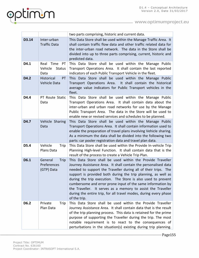
Project Title: OPTIMUM
Contract No. 636160 Project Coordinator: INTRASOFT International S.A.
Page 155
D1.4 – Conceptual Architecture
Version 2.0, Date 31/03/2017
two parts comprising, historic and current data.
D3.14 Inter-urban Traffic Data
This Data Store shall be used within the Manage Traffic Area. It shall contain traffic flow data and other traffic related data for the inter-urban road network. The data in the Store shall be divided into up to three parts comprising, current, historic and predicted data.
D4.1 Real Time PT Vehicle Status Data
This Data Store shall be used within the Manage Public Transport Operations Area. It shall contain the last reported indicators of each Public Transport Vehicle in the fleet.
D4.2 Historical PT Vehicle Data
This Data Store shall be used within the Manage Public Transport Operations Area. It shall contain the historical average value indicators for Public Transport vehicles in the fleet.
D4.4 PT Route Static Data
This Data Store shall be used within the Manage Public Transport Operations Area. It shall contain data about the inter-urban and urban road networks for use by the Manage Public Transport Area. The data in the Store will be used to enable new or revised services and schedules to be planned.
D4.7 Vehicle Sharing Data
This Data Store shall be used within the Manage Public Transport Operations Area. It shall contain information used to enable the preparation of travel plans involving Vehicle sharing. As a minimum the data shall be divided into the following two parts: car pooler registration data and travel plan data.
D5.4 Vehicle Trip Plans Data
This Data Store shall be used within the Provide In-vehicle Trip Planning High-level Function. It shall contain data that is the result of the process to create a Vehicle Trip Plan.
D6.1 General Trip Preferences (GTP) Data
This Data Store shall be used within the Provide Traveller Journey Assistance Area. It shall contain the personalised data needed to support the Traveller during all of their trips. The support is provided both during the trip planning, as well as during the trip execution. The Store is also used to prevent cumbersome and error prone input of the same information by the Traveller. It serves as a memory to assist the Traveller during the entire trip, for all travel modes, during every phase of the trip.
D6.2 Private Trip Plan Data
This Data Store shall be used within the Provide Traveller Journey Assistance Area. It shall contain data that is the result of the trip planning process. This data is retained for the prime purpose of supporting the Traveller during the trip. The most notable requirement is to react to the consequences of perturbations in the situation(s) existing during trip planning.
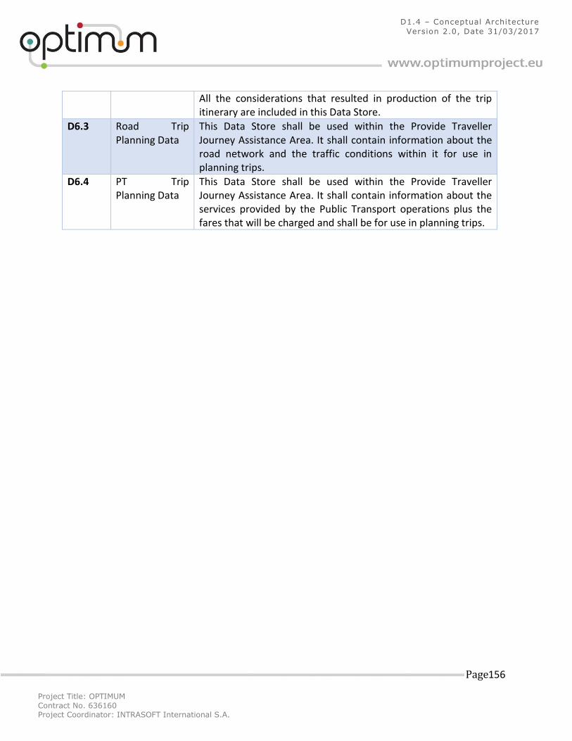
Project Title: OPTIMUM
Contract No. 636160 Project Coordinator: INTRASOFT International S.A.
Page 156
D1.4 – Conceptual Architecture
Version 2.0, Date 31/03/2017
All the considerations that resulted in production of the trip itinerary are included in this Data Store.
D6.3 Road Trip Planning Data
This Data Store shall be used within the Provide Traveller Journey Assistance Area. It shall contain information about the road network and the traffic conditions within it for use in planning trips.
D6.4 PT Trip Planning Data
This Data Store shall be used within the Provide Traveller Journey Assistance Area. It shall contain information about the services provided by the Public Transport operations plus the fares that will be charged and shall be for use in planning trips.