Embed Size (px)
Citation preview

5G Communication with a Heterogeneous, Agile Mobile network in the Pyeongchang Winter Olympic competitioN
Grant agreement n. 723247
Deliverable D2.2 5GCHAMPION Key Performance Indicator and use-cases defined and specification
document written
Date of Delivery: 31 March 2017
Editor: Giuseppe Destino
Associate Editors: Antonio Clemente
Authors:
Giuseppe Destino, Matti Latva-aho, Aarno Pärssinen, Marko Leinonen, Jussi Pajunpaa, Petri Uosukainen, Aki Korvala, Marko Pettissalo, Emilio Calvanese, Antonio Clemente, Jean-Baptiste Dore, Benoit Vautherin, Roc Maymo-Camps, Mathieu Gineste, Thibault Deleu, Ratul Banerjee, Junhyeong Kim, TaeYeon Kim
Dissemination Level: PU
Security: Public
Status: Final
Version: v1
File Name: 5GCHAMPION_D2.2_Final.pdf
Work Package: WP2

Title: Deliverable D2.2: 5GCHAMPION Key Performance Indicator and use-cases defined and specification document written
Date: 31-03-2016 Status: Final
Security: PU Version: v1
The information contained in this document is the property of the contractors. It cannot be reproduced or transmitted to thirds without the authorization of the contractors.
2 / 45
Abstract
This deliverables provides a full description of the use-cases, related KPIs and testbeds that will be demonstrated in the 5GCHAMPION project. Focus is on the application scenarios to be shown at the Olympic Games of Korea, in 2018. More specifically, the 5G CHAMPION project will showcase a 5G application experience for two users connected to two different 5G networks, one in Europe and one in Korea, and:(i) being served by either static or mobile mmW links, (ii) sharing a latency-critical, e.g., remote gaming or remote control using VR and (iii) demanding broadband services, for instance, shared VR content. Additionally, the 5GCHAMPION covers massive IoT applications and indoor-outdoor positioning by using a new approach for the 5G-satellite system interoperability. Finally, ultra-high data rate connectivity and high-speed train application scenarios will be considered too.
Index terms
Use-cases, mmW backhaul links, mmW ultra-high data rate indoor link, SDN/NFV, mobility, broadband, interoperability 5G-satellite.

Title: Deliverable D2.2: 5GCHAMPION Key Performance Indicator and use-cases defined and specification document written
Date: 31-03-2016 Status: Final
Security: PU Version: v1
The information contained in this document is the property of the contractors. It cannot be reproduced or transmitted to thirds without the authorization of the contractors.
3 / 45
Contents
1 Introduction ......................................................................................... 7
2 KPI definition by ITU ........................................................................... 8
2.1 Peak data rate 8
2.2 Peak spectral efficiency 9
2.3 User experienced data rate 9
2.4 5th percentile user spectral efficiency 9
2.5 Average spectral efficiency 9
2.6 Area traffic capacity 10
2.7 Latency 10
2.8 Connection density 11
2.9 Energy efficiency 11
2.10 Reliability 11
2.11 Mobility 11
2.12 Mobility interruption time 11
2.13 Bandwidth 11
3 28 GHz technology ............................................................................ 12
3.1 Regulation aspects for the 28 GHz band 12
3.1.1 European vision and field trial permissions 13
3.1.2 Korean vision and field trial permissions 14
3.2 The radio channel at 28 GHz 15
3.3 RF technology readiness 15
4 5G CHAMPION use-cases description ............................................ 17
4.1 Rationale of the selected use-cases 17
4.2 Frequency allocation for the 5GCHAMPION use-cases 18
4.3 Use-case 1: Wireless backhaul connecting heterogeneous radio access 19
4.4 Use-case 2: Ultra-high data-rate 5G downlink 21
4.5 Use-case 3: Accurate indoor-outdoor positioning. 22

Title: Deliverable D2.2: 5GCHAMPION Key Performance Indicator and use-cases defined and specification document written
Date: 31-03-2016 Status: Final
Security: PU Version: v1
The information contained in this document is the property of the contractors. It cannot be reproduced or transmitted to thirds without the authorization of the contractors.
4 / 45
4.6 Use-case 4: Satellite interoperability via 5G IoT devices 23
4.7 Use-case 5: High-user mobility 24
4.8 Use-case 6: Shared short-latency applications 25
4.9 Use-case 7: Shared broadband applications 27
5 Use-cases requirements ................................................................... 29
6 The role of 5GCHAMPION at the Winter Olympics ......................... 31
6.1 Target KPIs for 5G CHAMPION at the Winter Olympics 31
7 5GCHAMPION testing scenarios ..................................................... 33
7.1 Utilization of mmW backhaul in the 5GTN 34
7.2 Feasibility of ultra-high data rate 5G downlink 35
7.3 5G-GNSS positioning 36
7.4 Emulation of sub 6GHz satellite access with IoT devices 37
7.5 Simulated-environment for high user-mobility 38
7.6 5GCHAMPION application scenarios at the Winter Olympics 40
8 References ......................................................................................... 43

Title: Deliverable D2.2: 5GCHAMPION Key Performance Indicator and use-cases defined and specification document written
Date: 31-03-2016 Status: Final
Security: PU Version: v1
The information contained in this document is the property of the contractors. It cannot be reproduced or transmitted to thirds without the authorization of the contractors.
5 / 45
Table of Figures
Figure 1: Comparison of different usage scenario based on IMT-2020 requirements.............. 8
Figure 2 : Latency in Distributed and Centarlized core. ......................................................... 10
Figure 3: Frequency allocation in Europe around 28 GHz. ..................................................... 14
Figure 4. Heterogeneous network access connected via mmW backhaul. ............................ 19
Figure 5: High-data rate communication. ................................................................................ 21
Figure 6: 5G-GNSS positioning. .............................................................................................. 22
Figure 7: 5G-SatCOM use-case. ............................................................................................. 23
Figure 8: High-speed train use-case. ...................................................................................... 24
Figure 9 : Low-latency system architecture. ............................................................................ 25
Figure 10: Shared VR application. Alice and Bob are the avatars of two end-users connected to different networks in different locations. .............................................................................. 27
Figure 11: 5G demonstrations at the Winter Olympics of Korea in 2018. Blue sectors indicate the application domains targeted in the 5G CHAMPION project. ........................................... 31
Figure 12: Comparison betwee 5GCHAMPION and IMT-2020 target requirements. Level 3 = High importance, Level 2= Medium; Level 1 = Low. ............................................................... 32
Figure 13: 5GCHAMPION system architecture....................................................................... 33
Figure 14: Plan for multi-RAT connectivity via mmW backhaul in Oulu. ................................. 34
Figure 15: Testing scenario for 20Gbit/s ................................................................................. 35
Figure 16: Implementation of the positioning system. ............................................................. 36
Figure 17: Proposed satellite testbed for NB-IOT. .................................................................. 37
Figure 18 : Overview of the hardware platform. ...................................................................... 37
Figure 19: Link-level simulation for high user-mobility. ........................................................... 38
Figure 20: Simulation environment model. .............................................................................. 39
Figure 21: Ray-tracing simulation verification. ........................................................................ 40
Figure 22 : 5GCHAMPION deployment plan at the Winter Olympics in Korea. ..................... 40
Figure 23: Experimental moving hot-spot. .............................................................................. 41
Figure 24: Frequency allocation of the 5GCHAMPION PoCs. ................................................ 41

Title: Deliverable D2.2: 5GCHAMPION Key Performance Indicator and use-cases defined and specification document written
Date: 31-03-2016 Status: Final
Security: PU Version: v1
The information contained in this document is the property of the contractors. It cannot be reproduced or transmitted to thirds without the authorization of the contractors.
6 / 45
List of Acronyms 5G 5th Generation 5GTN 5G Test network API Application programming interface APN Access point name BBU Base band unit B-RU Backhaul radio unit CA Carrier aggregation CC Carrier components C-RAN Centralized radio access networks D-RAN Distributed radio access networks EHF Extremely high-frequency EIRP Effective Isotropic Radiated Power EPC Evolved packet core EU European union FACS Flexible Access Common Spectrum GNSS Global navigation satellite system IGS International GNSS service KPI Key performance indicator KR Korea LoS line-of-sight MBS Macro base stations MIMO Multiple-input-multiple-output MiWaves with Millimeter-Wave Small-Cell and Backhauling MiWEBA Millimetre-Wave Evolution for Backhaul and Access mmMagic Millimetre-Wave Based Mobile Radio Access Network for Fifth
Generation Integrated Communications mmW millimiter wave NFV Network function virtualization NLoS non-line of sight PoC Proof-of-concept PPP Point precise positioning PTMP Point-to-multipoint PTP Point-to-point QAM Quadrature amplitude modulation RAT Radio access technology RRH Remote radio head SC Small cells SDN Software defined networking SFMF Single-frequency multi-flow UHD ultra-high definition WP Work package
Title: Deliverable D2.2: 5GCHAMPION Key Performance Indicator and use-cases defined and specification document written
Date: 31-03-2016 Status: Final
Security: PU Version: v1
The information contained in this document is the property of the contractors. It cannot be reproduced or transmitted to thirds without the authorization of the contractors.
7 / 45
1 Introduction
During the last few years astonishing progresses have been made towards the definition and development of future 5G technology. Today, it is generally acknowledged that key building blocks of 5G are mmW access, evolved packet core with advanced NFV/SDN and reconfigurable waveforms. Once these technologies are commercially available and well integrated into a pervasive mobile network, 5G will be the enabler of a large variety of use-cases [1]-[3]. The ambition of the 5GCHAMPION project is to deliver at the Olympic Games of Korea, in 2018, the very first proof-of-concept (PoC) of a 5G system covering:
Enhanced mobile broadband with application scenarios such as shared virtual-reality and ultra-high definition video streaming
Time-critical use-cases with application scenarios as virtual-reality games and motion control
Moving hot-spots with application scenarios such as content sharing, video streaming, virtual-reality in moving bus.
Additionally, stand-alone 5G technology innovations will be developed for
(in Europe) massive IoT applications and connectivity via satellite links,
(in Europe) seamless indoor-outdoor positioning,
(in Europe) ultra-high data-rate,
(in Korea) high-user mobility in high-speed train scenarios.
Together with D2.1 [4] this deliverable provides the main guidelines for the work in the other WPs and more importantly, it gives the baseline information for the testing scenarios further developed in WP6.
The key performance indicators (KPI) are specified based on the 5GPPP use-case requirements [5]. Also, ITU 5G technology requirements [6] are used as criteria to assess the advances in the 5G technology development.
The reminder of this deliverable is organized as follows: in Section 2 we provide an overview of the KPIs along with their definitions. In Section 3, we address regulatory and technical aspects of the 28GHz technology, core of the mmW backhaul. Specifications related to band emissions are also given. Section 4 covers the use-case rationale and their definitions. Section 5 provides a map of the use-case with respect to the 5GPPP KPIs and 5G ITU technology requirements. Section 6 focuses on the demonstration contribution to be shown at the Winter Olympics. Finally, Section 7 describes the testing scenarios and specific KPIs.

Title: Deliverable D2.2: 5GCHAMPION Key Performance Indicator and use-cases defined and specification document written
Date: 31-03-2016 Status: Final
Security: PU Version: v1
The information contained in this document is the property of the contractors. It cannot be reproduced or transmitted to thirds without the authorization of the contractors.
8 / 45
2 KPI definition by ITU
In 2015, ITU released the recommendation M.2083 [7] where the capability of future 5G system has been defined. Focus was on providing qualitative requirements for enhanced mobile broadband, massive machine types of communication and ultra-reliable and low-latency communications. The radar chart shown in Figure 1 is one of the key result of that report. Use-cases have been defined along 8 dimensions (KPIs), capturing different performance as well as importance levels. In 2017, the general performance indicators have been revised and formalized in 13 technical performance requirements presented in the sequel [6].
M.2083-04
User experienceddata rate
Spectrumefficiency
Mobility
LatencyConnection density
Networkenergy efficiency
Area trafficcapacity
Enhanced mobilebroadband
Peakdata rate
Massive machinetype communications
Ultra-reliableand low latency
communications
Low
Medium
High importance
Figure 1: Comparison of different usage scenario based on IMT-2020 requirements.
2.1 Peak data rate
The peak data rate is the maximum achievable data rate (in bit/s) under ideal conditions, i.e.:
Error-free: perfect detection,
Full usage of radio resourses: all time-frequency resources are used for one data-link communication (physical layer synchronization, reference signals or pilots, guard bands and guard times are not considered).
For 5G mobile broadband applications, the minimum requirement for this KPI is as follows:
DL peak data rate is 20 Gbit/s,
UL peak data rate is 10 Gbit/s.

Title: Deliverable D2.2: 5GCHAMPION Key Performance Indicator and use-cases defined and specification document written
Date: 31-03-2016 Status: Final
Security: PU Version: v1
The information contained in this document is the property of the contractors. It cannot be reproduced or transmitted to thirds without the authorization of the contractors.
9 / 45
2.2 Peak spectral efficiency
The peak spectral efficiency is defined as the maximum peak data rate normalised by channel bandwidth (in bit/s/Hz).
For instance, considering an antenna configuration with 8 spatial layers in downlink and 4 in uplink, then the minimum requirements for peak spectral efficiencies for enhanced broadband applications are as follows:
DL peak spectral efficiency is 30 bit/s/Hz,
UL peak spectral efficiency is 15 bit/s/Hz.
2.3 User experienced data rate
User experienced data rate is the 5% point of the cumulative distribution function (CDF) of the user throughput. User throughput (during active time) is defined as the number of correctly received bits, i.e. the number of bits contained in the service data units (SDUs) delivered to Layer 3 of the protocol stack, over a certain period of time.
In a dense urban – enhanced Mobile BroadBand (MBB) test environment, the target requirements are
DL user experienced data rate is 100 Mbit/s,
UL user experienced data rate is 50 Mbit/s.
2.4 5th percentile user spectral efficiency
The 5th percentile user spectral efficiency is the 5% point of the CDF of the normalized user throughput. The normalized user throughput is defined as the number of correctly received bits divided by the channel bandwidth and is measured in bit/s/Hz.
Note that the channel bandwidth is given by the product of the effective bandwidth (operating bandwidth normalized appropriately considering the uplink/downlink ratio) and the frequency reuse factor.
For eMBB test environment, the corresponding 5G requirements are
Indoor hotspots: DL 0.3 bit/s/Hz, UL 0.21 bit/s/Hz,
Dense Urban : DL 0.225 bit/s/Hz, UL 0.15 bit/s/Hz,
Rural : DL 0.12 bit/s/Hz, UL 0.045 bit/s/Hz.
2.5 Average spectral efficiency
Average spectral efficiency is the aggregate throughput of N users divided by the channel bandwidth of a specific band divided by M Transmission Reception Point (TRxP) and is measured in bit/s/Hz/TRxP.
For eMBB application, the corresponding 5G requirements are
Indoor hotspots: DL 9 bit/s/Hz/TRxP, UL 6.75 bit/s/Hz/TRxP,
Dense Urban: DL 7.8 bit/s/Hz/TRxP, UL 5.4 bit/s/Hz/TRxP,
Rural: DL 3.3 bit/s/Hz/TRxP, UL 1.6 bit/s/Hz/TRxP.

Title: Deliverable D2.2: 5GCHAMPION Key Performance Indicator and use-cases defined and specification document written
Date: 31-03-2016 Status: Final
Security: PU Version: v1
The information contained in this document is the property of the contractors. It cannot be reproduced or transmitted to thirds without the authorization of the contractors.
10 / 45
2.6 Area traffic capacity
Area traffic capacity is the total traffic throughput served per geographic area (in Mbit/s/m2). It relates to the average user spectral efficiency, bandwidth and TRxP density.
The target value for Area traffic capacity in downlink is 10 Mbit/s/m2 in the Indoor Hotspot – eMBB test environment.
2.7 Latency
Generally, the notion of latency used for 5G time-critical application refers to user plane latency, that is the contribution of the radio network to the time from when the source sends a packet to when the destination receives it (in ms).
It is defined as the one-way time needed to deliver a message from the radio protocol layer 2/3 SDU ingress point to the radio protocol layer 2/3 SDU egress point of the radio interface in either uplink or downlink in the network for a given service in unloaded conditions, assuming the mobile station is in the active state.
Clearly, the network architecture has an impact on the latency KPI. For this reason, we distinguish between centralized and distributed core network architectures.
Distributed edge (core) enables to execute selected core functions and applications in cloud close to or shared with radio access network (RAN). As a result the data stream does not travel the entire network, but it is localized near the user access. With distributed edge the target UP latency between UE and Local GW is < 1ms.
On the other hand centralized core architecture is preferred for eMBB where the ultra low latency is not so critical. With centralized Core the target latency between UE and EPC is 4~20ms.
Figure 2 illustrates the aforementioned requirements for both centralised and distributed core.
MEC
Multi-RAT
Radio Unit
Local GW
Centralized EPC fucntions
1ms.
UE Distributed Edge
4-20ms.
EPC
Figure 2 : Latency in Distributed and Centarlized core.

Title: Deliverable D2.2: 5GCHAMPION Key Performance Indicator and use-cases defined and specification document written
Date: 31-03-2016 Status: Final
Security: PU Version: v1
The information contained in this document is the property of the contractors. It cannot be reproduced or transmitted to thirds without the authorization of the contractors.
11 / 45
2.8 Connection density
Connection density is the total number of devices fulfilling a specific quality of service (QoS) per unit area (per km2).
This requirement is defined for the purpose of evaluation in the mMTC usage scenario.
The minimum requirement for connection density is 1 000 000 devices per km2.
2.9 Energy efficiency
The energy efficiency does not have a clear target value. However, for mobile terminals, it is required long sleep ratios, i.e., the continuous period of time with no transmission (for network and device) and reception (for the device), should be sufficiently long.
2.10 Reliability
Reliability relates to the capability of transmitting a given amount of traffic within a predetermined time duration with high success probability. ITU defines the minimum requirement for ultra-reliable low-latency communications as 10-5 success probability of transmitting a layer 2 PDU (protocol data unit) of 32 bytes within 1 ms in channel quality of coverage edge for the Urban Macro-URLLC test environment, assuming small application data (e.g. 20 bytes application data + protocol overhead).
For eMBB, reliability is not defined.
2.11 Mobility
Mobility is the maximum mobile station speed at which a defined QoS can be achieved (in km/h). The following requirements are considered for the purpose of evaluation in the eMBB usage scenario.
Indoor hotspots: UL 1.5 bit/s/Hz, 10 km/h,
Dense Urban: UL 1.12 bit/s/Hz, 30 km/h,
Rural: UL 0.8 bit/s/Hz, 120 km/h,
Rural: UL 0.45 bit/s/Hz, 500 km/h.
2.12 Mobility interruption time
Mobility interruption time is the shortest time duration supported by the system during which a user terminal cannot exchange user plane packets with any base station during transitions.
The minimum requirement for mobility interruption time is 0 ms.
2.13 Bandwidth
Bandwidth is the maximum aggregated system bandwidth. The bandwidth may be supported by single or multiple radio frequency (RF) carriers. The requirement for bandwidth is at least 100 MHz. For carrier frequencies above 6GHz, the maximum bandwidths is 1 GHz.

Title: Deliverable D2.2: 5GCHAMPION Key Performance Indicator and use-cases defined and specification document written
Date: 31-03-2016 Status: Final
Security: PU Version: v1
The information contained in this document is the property of the contractors. It cannot be reproduced or transmitted to thirds without the authorization of the contractors.
12 / 45
3 28 GHz technology
In 5G, mmW systems is considered one of the enabling technologies for achieving high-data rate, low-latency and cell spectral-efficiency communications. However, as the technology requires new advances in the state-of-the-art of protocols, transmission technique and transceiver implementations, yet today, there is not a clear standard for mobile applications.
Key factors, which require further investigation and harmonization, are:
- Spectrum availability and regulations. Frequency bands allocated for mobile applications are defined between 24 GHz and 100 GHz. In accordance with ITU Resolution 238, the frequency bands 24.25-27.5 GHz, 37-40.5 GHz, 42.5-43.5 GHz, 45.5-47 GHz, 47.2-50.2 GHz, 50.4-52.6 GHz, 66-76 GHz and 81-86 GHz have allocations to the mobile service on a primary basis; and the frequency bands 31.8-33.4 GHz, 40.5-42.5 GHz and 47-47.2 GHz may require additional allocations to the mobile service on a primary basis. Frequency harmonization is needed.
- Radio propagation properties. In contrast to centimetre and lower carrier frequencies, the radio channel at the mmW band is much more sensitive to the environment and weather conditions [12]. In fact, several measurement campaign at 28, 38, 60 and 73 GHz have shown that propagation losses are typically higher, diffraction, reflection or bending are scarce, angular spread are small and multipath clusters are few [12]-[16]. In some conditions, the mmW radio channel can be characterized only by one dominant path, i.e., the line-of-sight. These properties has impact on the technology as call for high directional communications, large array gain and beamforming techniques.
- RF technology: RF technology has historically been dominated by semiconductor technologies such as GaAs and silicon (primarily SiGe/BiCMOS and CMOS, used in WiGig 60GHz so far). In fact, most of commercially available power amplifiers and low noise amplifiers, as well as enabling oscillators are based on these technologies. However, as new application scenarios have been addresses, such as macro-cell/small-cell mobile backhaul, requirements have been harder to meet. In [18], for instance, important indicators are the value of the output power, noise figure and phase noise, which in turns, have an impact the link budget and link distance.
In what follows, we focus on the specific 28GHz band.
3.1 Regulation aspects for the 28 GHz band
Based on analysis of Radio Access Technique Group (RATG) 1 (IMT-2000) & RATG 2 (IMT-Advanced)’s requirements considering market demand, technological progress and building of network, the ITU-R forecasts that between 1340 and 1960MHz of spectrum will be needed by 2020 [7]. Hence, various frequency bands including above 6GHz are being reviewed in order
for 5G communication. For instance, Korea officially proposed as a WRC‐19 agenda item that frequency ranges between 6GHz and 100GHz should be considered for IMT identification
during the 4th meeting of the APT Conference Preparatory Group for WRC‐15 (APG15‐2).
Note that the FCC has aggressively addressed future spectrum need in the US through its "Spectrum Frontier" 5G initiative which makes add in total 10.85 GHz of Spectrum Bands above 24 GHz For Mobile Radio Services, et al. (including 27.5 – 28.35 GHz, 37 – 38.6 GHz, 38.6 –

Title: Deliverable D2.2: 5GCHAMPION Key Performance Indicator and use-cases defined and specification document written
Date: 31-03-2016 Status: Final
Security: PU Version: v1
The information contained in this document is the property of the contractors. It cannot be reproduced or transmitted to thirds without the authorization of the contractors.
13 / 45
40 GHz and 64 – 71 GHz). Note in particular that at the World Radio Conference 2015, there was no agreement on the 28 GHz band which is likely not to be available world-wide. Still, the US has included the band in its nation-wide ruling and we expect that it will also be available in Korea. Indeed, to the best of our knowledge, Korea proposed 24.25~29.5GHz to the ITU-R. Europe is expected to rather follow the World Radio Conference 2019 agenda which address mmW spectrum as follows:
Satellite related Agenda items:
WRC’19 Agenda item 1.5: …consideration of the use of the frequency bands 17.7-19.7 GHz (space-to-Earth) and 27.5-29.5 GHz (Earth-to-space) by earth stations in motion (ESIMs) communicating with geostationary space stations in the fixed-satellite service.
WRC’19 Agenda item 1.6: …development of a regulatory framework for non-GSO FSS satellite systems that may operate in the frequency bands 37.5-39.5 GHz (space-to-Earth), 39.5-42.5 GHz (space-to-Earth), 47.2-50.2 GHz (Earth-to-space) and 50.4-51.4 GHz (Earth-to-space).
IMT related Agenda items:
WRC’19 Agenda item: …identification of frequency bands for the future development of International Mobile Telecommunications (IMT), including possible additional allocations to the mobile service on a primary basis … including possible additional allocations to the mobile services on a primary basis in portion(s) of the frequency range between 24.25 and 86 GHz.
As many contributions are including 28GHz, this frequency will be the first priority used for 5G deployments. However, it remains the need of global harmonization due to frequency band discrepancies in specific nations.
3.1.1 European vision and field trial permissions
As illustrated in Figure 3, the frequency band at 28GHz is not allocated for mobile services (MS) in Europe. However, due to the strong opening from other countries (US, Korea and Japan), the European Commission (EC) recommends the 24.25-27.5 GHz as a pioneer band for 5G above 24 GHz [19], however, with a request of harmonisation measures, especially for the Earth Exploration Satellite Service (EES) and Space Research Service (SRS).

Title: Deliverable D2.2: 5GCHAMPION Key Performance Indicator and use-cases defined and specification document written
Date: 31-03-2016 Status: Final
Security: PU Version: v1
The information contained in this document is the property of the contractors. It cannot be reproduced or transmitted to thirds without the authorization of the contractors.
14 / 45
Figure 3: Frequency allocation in Europe around 28 GHz.
3.1.2 Korean vision and field trial permissions
The frequency bands in the range of 24~26.5GHz were defined as unlicensed frequency bands, also called FACS(Flexible Access Common Spectrum), by Korean government in March 2016. These bands are generally prioritized for field trial. For instance, ETRI gave a successful field trial of MHN prototype system at Seoul subway line 8 in February 2017, which was the world first millimetre-wave prototype system demonstrated in the running subway train with passengers, showing a peak data rate of 1.25Gbit/s. Also, at Pyeongchang Winter Olympics of 2018, the FACS is prioritized.
However, several companies and operators in the Korea are working closely to conduct field trials at 28GHz too. For instance, Samsung demonstrated their 28GHz system showing a peak date rate of up to 2.59Gbit/s at speeds of nearly 150km/h by adopting beam-tracking techniques, and SK Telecom deployed world’s largest mmW 5G trial network with Ericsson at BMW driving center located in Incheon, Korea, and also demonstrated ‘T5’, the world’s first 5G connected car in November 2016 showing a peak data rate of 3.6Gbit/s in mobility of 170km/h.
Followings are the details about the regulations of FACS in Korea, which indicates that the Korean prototype system with bandwidth of up to 1GHz is mandatory to meet the EIRP requirement, where the maximum EIRP allowed is 36dBm.
Any equipment that uses spectrum bands in the range of 24-26.5 GHz must comply with the following conditions:
Conducted net power should be lower than or equals to 100 mW, and average power density should be lower than or equals to 6 dBm/MHz.
Absolute antenna gain should be lower than or equals to 16 dBi. If the gain is larger than 16 dBi, the conducted net power must be decreased to the amount of the difference.
Occupied frequency bandwidth should remain within a pre-determined range.
Unwanted emission (out-of-band emission plus spurious emission) in out of the band should be lower than or equals to the below references.

Title: Deliverable D2.2: 5GCHAMPION Key Performance Indicator and use-cases defined and specification document written
Date: 31-03-2016 Status: Final
Security: PU Version: v1
The information contained in this document is the property of the contractors. It cannot be reproduced or transmitted to thirds without the authorization of the contractors.
15 / 45
Frequency Average value Reference bandwidth
below 1 GHz -36 dBm 100 kHz
above 1 GHz -30 dBm 1 MHz
Spurious emission should be lower than or equals to the below references when the equipment is in the status of reception or not in transmission.
Frequency Average value Reference bandwidth
below 1 GHz -54 dBm 100 kHz
above 1 GHz -47 dBm 1 MHz
Each equipment should use an identification code to keep other devices from malfunctioning due to the equipment or keep the equipment from malfunctioning due to other devices.
3.2 The radio channel at 28 GHz
The fundamental effects of signal propagation in wireless radio channels are independent in frequency. However, their effect and strength can vary with the frequency and thus wavelength. Reflections at materials with rough surfaces for example might be considered as specular at low frequency but can become diffuse when the wavelength comes to the order of magnitude of the roughness. It is therefore necessary to review existing knowledge and mobile radio channel models on the lower frequency bands and check their applicability for the 28 GHz band.
Measurements of 28 GHz urban access channels have shown a significant number of multipath components (MPC) in addition to the line-of-sight (LOS) propagation. The LOS and MPC components are highly affected by obstruction through moving objects (e.g. cars), humans, as well as static objects, such as street furniture [20] .The strength and propagation delay of MPCs and effect of such shadowing events can be well explained by geometrical considerations of the environment. Reflections from surrounding buildings for example can be a quite deterministic and static source of multipath propagation.
The ground reflection can constitute a significant source of small scale fading on the LOS component, as its excess propagation delay is very small. Depending on the distance and height of the transmitting and receiving stations, this can lead to severe, frequency flat attenuation of the received power, even for wideband signals [21].
As the Doppler frequency offset scales with the carrier frequency of the signal, its magnitude values are much higher at 28 GHz than at the frequencies used for current mobile radio networks. This effect can be calculated in a deterministic way for the individual propagation components when the geometry of the environment and the movement of objects are known.
3.3 RF technology readiness
Early trials for integrated phased arrays have been published for various frequencies in [22]-[27]. However, soon 60GHz band as ISM band became de facto for short range mmW trials from prototype systems to WiGig standard [28]-[34].

Title: Deliverable D2.2: 5GCHAMPION Key Performance Indicator and use-cases defined and specification document written
Date: 31-03-2016 Status: Final
Security: PU Version: v1
The information contained in this document is the property of the contractors. It cannot be reproduced or transmitted to thirds without the authorization of the contractors.
16 / 45
But chipset availability for 28GHz RF is limited. Samsung led developments in the 28 GHz band together with NYU and developed early prototypes. After the WRC-15, many chipset vendors started to develop 28 GHz technologies, which led to the announcement of Intel and Qualcomm plans to support 28 GHz in their 5G chipsets in 2018. NEC released a massive MIMO antenna at 28 GHz band with 500 elements, which will be used in the earliest deployment of 5G in Japan Recently, a 28GHz IC was published by IBM and Ericsson representing state-of-the-art in the integrated solutions for 5G.
One specific challenge is power generation in transmitters at mmW frequencies. Various power amplifiers have been published in the frequency range of interest from bulk CMOS to GaN as depicted with some examples in [36]-[42]. However, achieving Watt level output power in sufficiently linear operation region is not straightforward although output power is much lower than available currently for base station amplifiers at frequencies of 6GHz and below. And highly efficient modulations like OFDM require up to 10dB back off for sufficient signal quality (EVM) for 64-QAM. That is feasible only for GaN and HEMT technologies at the moment and is likely beyond the capability for any silicon based technology also in the future. In addition, no proper linearization techniques to improve power efficiency for very wideband signals at mmW range have not been demonstrated so far. As the output power per PA is anyways limited the feasibility to improve overall power efficiency of the system will be more limited than in case of GHz range base stations.
For the reasons above individual antenna elements will have fundamental limitations in terms of output power. That leads to large phased arrays in order to achieve medium to long ranges requires specifically for mobile backhaul applications and therefore III-V technologies will play a role at least in power stage of mmW transceiver. However, highly integrated solutions for the rest of the transceiver seem feasible in the future although design are not straightforward and early prototypes will utilize also discrete components having better availability in the market due to other applications using roughly the same frequency range.

Title: Deliverable D2.2: 5GCHAMPION Key Performance Indicator and use-cases defined and specification document written
Date: 31-03-2016 Status: Final
Security: PU Version: v1
The information contained in this document is the property of the contractors. It cannot be reproduced or transmitted to thirds without the authorization of the contractors.
17 / 45
4 5G CHAMPION use-cases description
4.1 Rationale of the selected use-cases
The primary goal of the 5GCHAMPION project is demonstrate, for the first time, the integration of a 5G system prototype in which key components are: a millimetre-wave mobile backhaul radio link using a carrier frequency above 24 GHz band and vEPC with SDN and NFV. Also, we benefit of the availability of two different system implementations (European and Korean) to analyse the interoperability and agile reconfiguration of the core and air interface. Additionally, the 5GCHAPION project addresses, for the first time, the potential of 5G-satellite interoperability for a) satellite access with IoT devices and accurate indoor-positioning. For this context, a Software Reconfiguration Framework is defined which enables a continued upgrade of target User Equipment to novel essential features to be defined in the future.
Table 1 shows the selected use-cases along with the target test-beds and KPIs.
No Use-case Target test-bed Targets and KPI
1 Stationary multi-RAT hot-spot connected via mmW backhaul to 5GTN
Stand-alone EU testbed, Oulu 100 Mbit/s user exp.
2.5 Gbit/s mmW backhaul
heterogeneous access
SDN/NFV in EPC
2 Ultra-high data rate 5G downlink
Stand-alone EU testbed, Oulu 20 Gbit/s
3 Indoor-outdoor positioning Stand-alone EU testbed, Oulu 5G mmW and GNSS
interoperability
Accurate positioning 4 Satellite connectivity with 5G
IoT devices Stand-alone EU testbed, Oulu SatCOM and 5G
interoperability
5 High user-mobility Stand-alone, KR testbed 2.5 Gbit/s mmW wireless
backhaul with 500 Km/h mobility
100 Mbit/s user exp. 6 Shared short-latency
applications (e.g. multiplayer remote gaming and multi-remote control)
EU-KR 5G system Korea, PeyongChang
Intersystem interoperability
2ms over-the-air latency
SDN/NFV in vEPC
7 Shared broadband applications EU-KR 5G system Korea, PeyongChang/Oulu
Intersystem interoperability
100 Mbit/s user-experience
Bus mobility < 80km/h
2.5 Gbit/s mmW wireless backhaul
SDN/NFV in vEPC
Table 1: 5G CHAMPION selected use-cases.

Title: Deliverable D2.2: 5GCHAMPION Key Performance Indicator and use-cases defined and specification document written
Date: 31-03-2016 Status: Final
Security: PU Version: v1
The information contained in this document is the property of the contractors. It cannot be reproduced or transmitted to thirds without the authorization of the contractors.
18 / 45
4.2 Frequency allocation for the 5GCHAMPION use-cases
Use-cases will be studied and tested using the following frequency allocation:
mmW PoC Frequency band
EU 26.5 - 27.3 GHz
KR 25.14 - 26.14 GHz
Table 2: Frequency allocation for EU and KR PoC.
The motivation is three-fold:
i. Industrial and market interests: network manufactures and operators have strong incentives to develop technology in the range of 28GHz as first 5G deployments are likely to use this frequency band
ii. Regulatory study: regulatory bodies have strong interests to determine harmonization mechanisms towards a global definition of mmW band for 5G
iii. Technology: as shown in Section 3.2, 28GHz band has better channel propagation properties than other mmW bands (e.g., 60 GHz). Also, at 28 GHz, power efficiency is higher than that at higher frequencies as with the increase of the frequency, more compromises and parallelism are needed meet link-budget requirements.
Title: Deliverable D2.2: 5GCHAMPION Key Performance Indicator and use-cases defined and specification document written
Date: 31-03-2016 Status: Final
Security: PU Version: v1
The information contained in this document is the property of the contractors. It cannot be reproduced or transmitted to thirds without the authorization of the contractors.
19 / 45
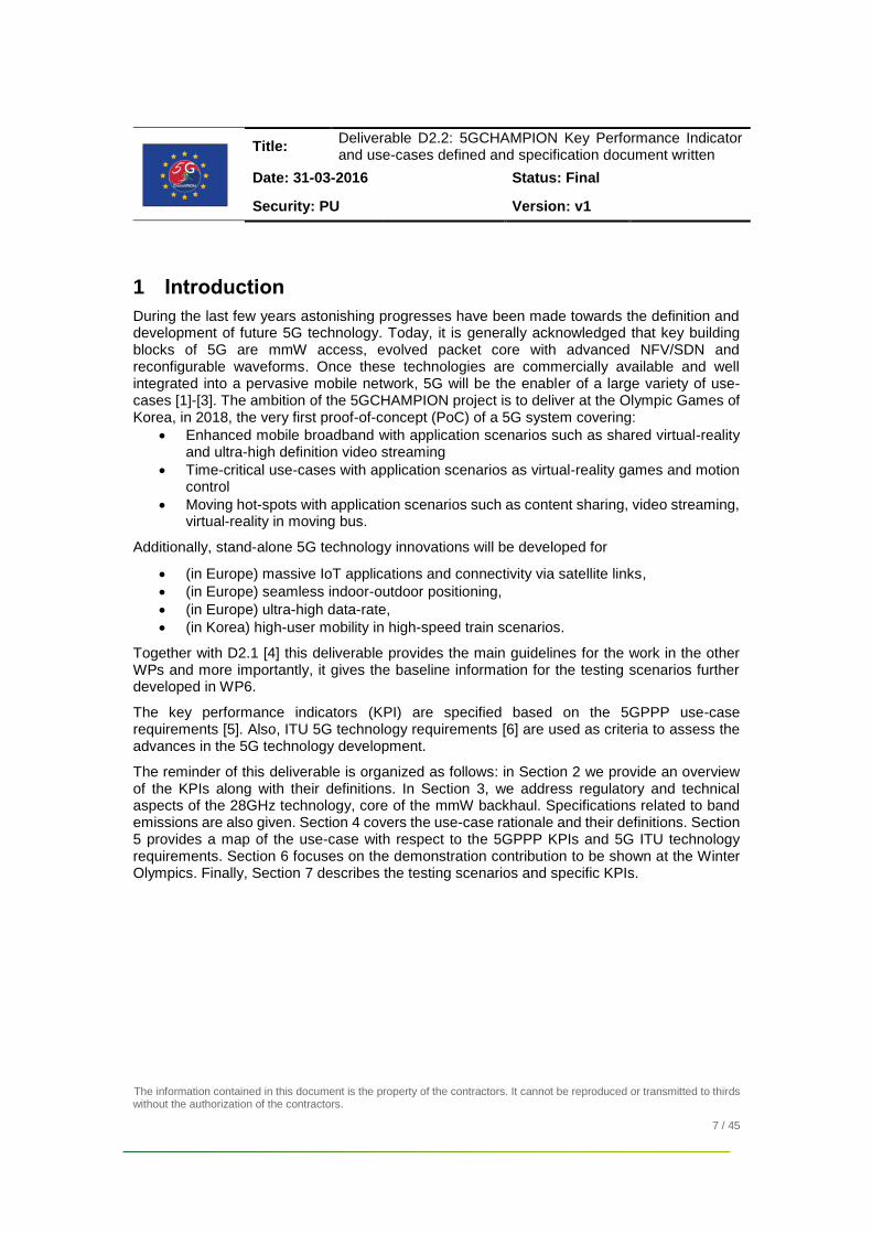
4.3 Use-case 1: Wireless backhaul connecting heterogeneous radio access
This use-case covers the “classical” scenario of providing mobile services, e.g., MBB, IoT and internet-based applications, in areas where one or more base-stations (of different networks) are only connected via wireless backhaul to the core network. More specifically, we intend to demonstrate the capability of 5G system to support heterogeneous networks and dense user connectivity, for instance, in office and urban environments.
For instance, this use-case will cover application scenarios as:
Web-browsing: end-users can use the network to experience fast web-surfing, online shopping, social-networks, etc.
Content sharing: end-users can use the network to share real-time photos, short-videos as well as co-create document.
Monitoring of the environment: end-users can use cloud-services augmented via real-time IoT sensing information.
Figure 4. Heterogeneous network access connected via mmW backhaul.
As illustrated in Figure 4, the enablers are: IoT/Wi-Fi/4G base stations, IP-traffic aggregator, 5G backhaul units (working as IP-traffic pipeline), service gateway, 5G core networks and cloud services.
The typical environment can be indoors or urban areas or, more generally, areas where new network coverage is needed. The backhaul units can be placed in indoors as well as outdoors.
Based on the use-case analysis in [43], web-browsing applications generate ON/OFF type of IP traffic, in which sessions are periodically open and closed (ON for downloading and OFF when users read). The typical user-rate is 0.05 Mbps and the end-to-end latency (measured as the round-trip-time) is less than 150 ms (4G).

Title: Deliverable D2.2: 5GCHAMPION Key Performance Indicator and use-cases defined and specification document written
Date: 31-03-2016 Status: Final
Security: PU Version: v1
The information contained in this document is the property of the contractors. It cannot be reproduced or transmitted to thirds without the authorization of the contractors.
20 / 45
For content sharing, the traffic is FTP like (as specified in 3GPPP). In this case, the average user-rate is much higher than that for web-browsing as content are typically richer. The study in [43] provides a figure of 135Mbit/s with peaks of 200 Mbit/s.
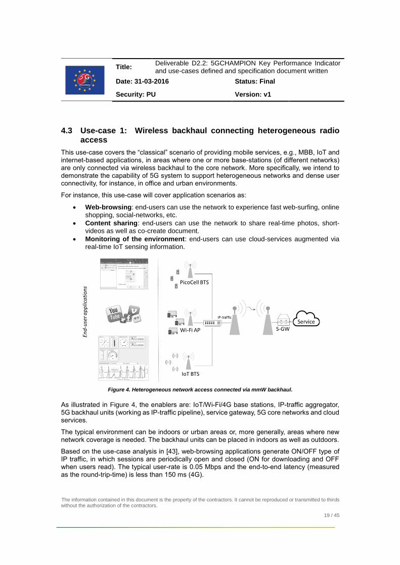
In summary, Table 6 provides key requirements for this use-case based on 5G-PPP criteria. Table 7 shows how ITU technology requirements can be verified in this use-case.
Finally, in Section 7.1 we specify a test scenario using technology with readiness level 5-6.

Title: Deliverable D2.2: 5GCHAMPION Key Performance Indicator and use-cases defined and specification document written
Date: 31-03-2016 Status: Final
Security: PU Version: v1
The information contained in this document is the property of the contractors. It cannot be reproduced or transmitted to thirds without the authorization of the contractors.
21 / 45
4.4 Use-case 2: Ultra-high data-rate 5G downlink
This use-case covers a classic 5G downlink scenario where the base station is capable of very high data-rate communications. The concept is depicted in Figure 5. The main driver of this use-case is the exponential growing of interests of VR and AR, (e.g., immersive experience in 3D virtual reality), holographic as well as high-definition (4k, 8k) video streaming applications for mobile terminals.
Figure 5: High-data rate communication.
The high-data rate connectivity can be understood either toward a single user or aggregated to multiple users. The end-users are wireless devices supporting high-data rate. For instance, mobile phones, tablets as well as any other AR/VR mobile devices.
The typical environment is outdoor or indoor short-range as high-data rate is likely to be achieved only in line-of-sight channel conditions.
As reference application scenarios, we consider:
Ultra-high definition video distribution: this refers to a scenario where video/mass-data content can be distributed to the individual users simultaneously (broadcast). For example, there are multiple screens that show the same video in a public event or in a train/airplane.
Ultimate VR applications : this refers to a scenario where one or more users is requesting a VR content with 24K-3D video quality, in which the expected a data-rate per video is > 3Gbit/s.
The 5G-PPP requirements characterizing this use-case are shown in Table 6.
The testing scenario is detailed in 7.2 and it targets a technology readiness level 2-3.

Title: Deliverable D2.2: 5GCHAMPION Key Performance Indicator and use-cases defined and specification document written
Date: 31-03-2016 Status: Final
Security: PU Version: v1
The information contained in this document is the property of the contractors. It cannot be reproduced or transmitted to thirds without the authorization of the contractors.
22 / 45
4.5 Use-case 3: Accurate indoor-outdoor positioning.
This use-case covers positioning applications for stationary 5G terminals or moving vehicles. Navigation/positioning in indoor/outdoor environments is, for example, a typical one. Differently from the state-of-the-art positioning solutions, we address a solution based on a combination of GNSS and 5G mmW technologies to enable sub-meter location accuracy in indoor-outdoor, seamlessly. The concept scenario is depicted in Figure 6.
Figure 6: 5G-GNSS positioning.
Possible application scenarios are listed in the table below:
Application scenario Indoor
environment Outdoor
environment
Autonomous vehicles
Drones
Guidance of visually impaired people
Guidance of consumers in shopping malls
Indoor robotics
Augmented reality
Table 3: Application scenario for 5G-GNSS positioning.
The 5G-PPP requirements characterizing this use-case are shown in Table 6.
The testing scenario is detailed in 7.3, in which we aim at a technology readiness level 4-5.

Title: Deliverable D2.2: 5GCHAMPION Key Performance Indicator and use-cases defined and specification document written
Date: 31-03-2016 Status: Final
Security: PU Version: v1
The information contained in this document is the property of the contractors. It cannot be reproduced or transmitted to thirds without the authorization of the contractors.
23 / 45
4.6 Use-case 4: Satellite interoperability via 5G IoT devices
5G context offers a promising opportunity to offer an integrated satellite/cellular service to 5G User Equipment ‘as is’ as depicted in Figure 7. This use-case can be made possible by taking advantage of the flexible front ends that will be implemented in User Equipment to operate in a wide range of frequency bands sub 6 GHz and the flexible radio interface designed to provide narrow band and wide band communications over extended coverage while optimizing the UE power consumption. Furthermore, we define an optional Software Reconfiguration framework which targets User Equipment of extended time-in-market, as it may for example occur for automotive components with satellite access capabilities, requiring a lifetime of 10 years and above. Reconfiguration capabilities will enable the additional of novel essential features to be defined after market introduction of devices.
Figure 7: 5G-SatCOM use-case.
Several technical and scientific challenges and requirements need to be addressed to allow a global, satellite and terrestrial deployment of cellular network for efficient IoT access. More precisely, in terms of satellite communications, the following technologies are required:
Modification of the 5G terminal as well as waveform parameterization to handle satellite communication.
GSO and NGSO resource allocation schemes.
Adaptation of the satellite payload and antenna design to handle M2M coverage and services.
The 5G-PPP requirements characterizing this use-case are shown in Table 6.
The testing scenario is detailed in 7.4, in which we aim at a technology readiness level 4-5.

Title: Deliverable D2.2: 5GCHAMPION Key Performance Indicator and use-cases defined and specification document written
Date: 31-03-2016 Status: Final
Security: PU Version: v1
The information contained in this document is the property of the contractors. It cannot be reproduced or transmitted to thirds without the authorization of the contractors.
24 / 45
4.7 Use-case 5: High-user mobility
This use-case covers the problem of moving hot-spots and, especially, content delivery in on
high-speed transportations such as bus, subway and high-speed trains. More specifically, the
challenge is to providing high-data rate connectivity at 500 km/h via mmW wireless backhaul.
In contrast to existing solutions, such as microwave access (WiMAX), long term evolution (LTE)
and LTE-Advanced (LTE-A) as well as some other commercial products, the target is to
achieve backhaul link with 2.5 Gbit/s and at least 100 Mbps user experience. The use-case
concept is depicted in Figure 8.
Figure 8: High-speed train use-case.
The key components are mmW wireless backhaul, heterogeneous radio-access for end-users
and distributed vEPC for content/service management.
Possible application scenarios are: video streaming (2K or 4K), web browsing and content
sharing and video conference.
In Table 6, this use-case is characterized with respect to 5G-PPP requirements.
The testing scenario is detailed in 7.5, in which we aim at a technology readiness level 2.

Title: Deliverable D2.2: 5GCHAMPION Key Performance Indicator and use-cases defined and specification document written
Date: 31-03-2016 Status: Final
Security: PU Version: v1
The information contained in this document is the property of the contractors. It cannot be reproduced or transmitted to thirds without the authorization of the contractors.
25 / 45
4.8 Use-case 6: Shared short-latency applications
One of the key challenge in 5G is to enable short-latency (time critical) applications such are factory automation, tactile Internet, remote control and automated guided vehicles. Generally, key aspects to be considered is to transfer and receive data in very short time (Table 4 shows typical values based on the application scenario), guarantee successful message/data transmission and endurance against possible outage conditions.
Figure 9 shows the system concept where both transmitter and are connected via 5G link to a service located, for instance, in a cloud.
In contrast to other application scenarios/use-cases, the mmW radio interface is utilized mainly to transfer short messages from the transmitter to the server and back to the receiver. Key is the design of a radio interface supporting short packets (in terms of bits and time duration) and short radio frames.
Figure 9 : Low-latency system architecture.
Application scenario Latency requirement
Factory automation <= 1 ms
Motion control <= 1 ms
Tactile internet 1 ms
Smart grid 3-5 ms
Intelligent transport systems 5 ms
Remote VR game control <= 5 ms
Remote control 5-100 ms
Automated guided vehicle 15-20 ms
Process automation 100 ms
Table 4: Time-critical application scenario.
An extension of the aforementioned application scenarios and also main objective of the 5GCHAMPION project is to allow end-users (TX and RX) to operate in different locations, but being coordinated by the same server (shared controller). This is hereafter referred to as

Title: Deliverable D2.2: 5GCHAMPION Key Performance Indicator and use-cases defined and specification document written
Date: 31-03-2016 Status: Final
Security: PU Version: v1
The information contained in this document is the property of the contractors. It cannot be reproduced or transmitted to thirds without the authorization of the contractors.
26 / 45
shared low-latency application. For instance, we can imagine an interactive-VR (e.g. VR on-line game) application where players are virtually playing and interacting together.
As before, the challenge is not on the distribution of the VR content, but it is to minimize the end-to-end latency.
In Table 6, this use-case is characterized with respect to 5G-PPP requirements.
The testing scenario is detailed in Section 7.6. We aim at a technology readiness level 4-5.

Title: Deliverable D2.2: 5GCHAMPION Key Performance Indicator and use-cases defined and specification document written
Date: 31-03-2016 Status: Final
Security: PU Version: v1
The information contained in this document is the property of the contractors. It cannot be reproduced or transmitted to thirds without the authorization of the contractors.
27 / 45
4.9 Use-case 7: Shared broadband applications
Use-case 7 covers shared broadband services, in which multiple users, located in different networks, can share in real-time a common application/content. For instance, a possible application scenario is the shared VR scene, where two users, physically located in different locations, meet each other in a common VR world (Figure 10) as avatars. The main difference to use-case 6 is that VR content is now provided from the network to the end-users, which can share a common experience with the virtual environment, tough only passively (no touch or feedback from virtual entities). Therefore, the focus in this application scenario is not on the interaction (latency), but it is on the availability of high-data rate links to permit loading and smooth play of the VR content.
Based upon the current VR technology (pre-VR, entry-level, advanced-VR) key network requirements are shown in Table 5.
Feature Pre-VR Entry-level VR Advanced-VR
Video resolution 4K-2D 8K-2D 12K-2D
Frame rate 30 30 60
Typical video bit-rate 16Mbit/s 64Mbit/s 279 Mbit/s
Typical network bandwidth
25Mbit/s 100Mbit/s 418Mbit/s
Typical network RTT 40 ms 30 ms 20 ms
Typical packet loss 1.4e-4 1.5e-5 1.9e-6
Table 5: VR requirements for shared content [44].
Figure 10: Shared VR application. Alice and Bob are the avatars of two end-users connected to different networks in different locations.

Title: Deliverable D2.2: 5GCHAMPION Key Performance Indicator and use-cases defined and specification document written
Date: 31-03-2016 Status: Final
Security: PU Version: v1
The information contained in this document is the property of the contractors. It cannot be reproduced or transmitted to thirds without the authorization of the contractors.
28 / 45
In Table 6, this use-case is characterized with respect to 5G-PPP requirements.
The testing scenario is detailed in Section 7.6. We aim at a technology readiness level 4-5.

Title: Deliverable D2.2: 5GCHAMPION Key Performance Indicator and use-cases defined and specification document written
Date: 31-03-2016 Status: Final
Security: PU Version: v1
The information contained in this document is the property of the contractors. It cannot be reproduced or transmitted to thirds without the authorization of the contractors.
29 / 45
5 Use-cases requirements
Us
e-c
ase
1
Us
e-c
ase
2
Us
e-c
ase
3
Us
e-c
ase
4
Us
e-c
ase
5
Us
e-c
ase
6
Us
e-c
ase
7
KPI Range x
Device Density
High : ≥ 10000 devices per km2 x
Medium : 1000 – 10000 devices per km2 x x x
Low : < 1000 devices per km2 x x
Mobility No: Static users x x
Low: Pedestrians (0-3 km/h) x x x
Medium: Slow moving (3 – 50 km/h) x x
High: Fast moving (> 50 km/h) x x x x
Infrastructure Limited: No infrastructure available or only macro cell coverage
x x x
Medium density: Small amount of small cells x Highly available infrastructure: Big number of small cells available
x x
Traffic Type Continuous x x
Bursty x
Event driven
Periodic x
All types x x x x
User Data Rate
Very high data rate : ≥ 1 Gbit/s x x High : 100 Mbps – 1 Gbit/s x x
Medium : 50 – 100 Mbps x x
Low : < 50 Mbps x x x
Latency High: > 50 ms x x x x Medium: 10 – 50 ms x
Low: 1 – 10 ms x x
Reliability Low: < 95%
Medium: 95 – 99% x x x x x High: > 99% x
Availability (related to coverage)
Low: < 95% x
Medium: 95 – 99% x x x x x x High: > 99%
5G Service Type,
comprising
extreme Mobile Broadband is the key service requirement.
x x x
uMTC, where the reliability is the key service requirement
x x x
The massive connectivity is the key service requirement.
x x x x
Table 6: Mapping of the 5GCHAMPION use-cases to 5G-PPP requirements.
Title: Deliverable D2.2: 5GCHAMPION Key Performance Indicator and use-cases defined and specification document written
Date: 31-03-2016 Status: Final
Security: PU Version: v1
The information contained in this document is the property of the contractors. It cannot be reproduced or transmitted to thirds without the authorization of the contractors.
30 / 45
KPI ITU Target 5GCHAMPION Applicability
Bandwidth Minimum 100 MHz Use-case 1,2,6 and 7
Peak data rate DL:20 Gbit/s; UL: 10 Gbit/s Use-case 2
Peak spectral efficiency DL: 30 bps/Hz; UL 15 bps/Hz Use-case 2
Cell spectral efficiency 3x IMT-A Use-case 1, 6 and 7
5th %-tile user spectral efficiency 3x IMT-A Use-case 1, 6 and 7
User experienced data rate No target KPI Use-case 1 and 7
Area traffic capacity No target KPI Use-case 1
Latency (Control Plane) 10ms Use-case 1, 6 and 7
Latency (User Plane) eMBB: 4ms UL, 4ms DL
URLLC: 0.5ms UL, 0.5ms DL
Use-case 1, 6 and 7
Not Applicable
Latency for infreq. Small packets
< 10s in UL and MCL = 164dB Not Applicable
Mobility interruption time 0ms Use-case 4, 6 and 7
Reliability General URRLX: (1-10-5)/1ms
eV2X: (1-10-5)/[2-10]ms
Not Applicable
Use case 6
Connectivity density 1 Million devices/km2 Use-case 4
UE battery life Beyond 19 years Use-case 4
Coverage MCL = 164dB, for 160bps Use-case 6, 7
Extreme Coverage MCL = 140dB @2Mbps/60kbps
DL/UL 143dB @1M/30k
Use-case 6, 7
Mobility speed Up to 500 km/h Use-case 5
Network energy efficiency Efficient data delivery and granular DTX/DRX Not applicable
UE energy efficiency Efficient data delivery and granular DTX/DRX Not applicable
Table 7: Mapping of ITU technology requirements to 5GCHAMPION use-cases.
Title: Deliverable D2.2: 5GCHAMPION Key Performance Indicator and use-cases defined and specification document written
Date: 31-03-2016 Status: Final
Security: PU Version: v1
The information contained in this document is the property of the contractors. It cannot be reproduced or transmitted to thirds without the authorization of the contractors.
31 / 45
6 The role of 5GCHAMPION at the Winter Olympics
The 5G CHAMPION project will showcase a 5G application experience for two users connected to two different 5G networks, one in Europe and one in Korea, and:(i) being served by either static or mobile mmW links, (ii) sharing a latency-critical, e.g., remote gaming or remote control using VR and (iii) demanding broadband services, for instance, shared VR content. More specifically, use-case6 and use-case7 will be used as references to show pilot 5G applications.
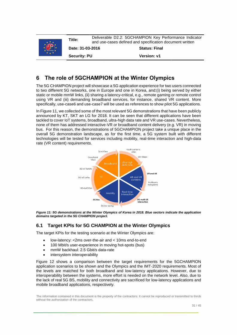
In Figure 11, we collected some of the most relevant 5G demonstrations that have been publicly announced by KT, SKT an LG for 2018. It can be seen that different applications have been tackled to cover IoT systems, broadband, ultra-high data rate and VR use-cases. Nevertheless, none of them has addressed interactive-VR or broadband content delivery (e.g. VR) in moving bus. For this reason, the demonstrations of 5GCHAMPION project take a unique place in the overall 5G demonstration landscape, as for the first time, a 5G system built with different technologies will be tested for services including mobility, real-time interaction and high-data rate (VR content) requirements.
Figure 11: 5G demonstrations at the Winter Olympics of Korea in 2018. Blue sectors indicate the application domains targeted in the 5G CHAMPION project.
6.1 Target KPIs for 5G CHAMPION at the Winter Olympics
The target KPIs for the testing scenario at the Winter Olympics are:
low-latency: <2ms over-the-air and < 10ms end-to-end
100 Mbit/s user-experience in moving hot-spots (bus)
mmW backhaul: 2.5 Gbit/s data-rate
intersystem interoperability
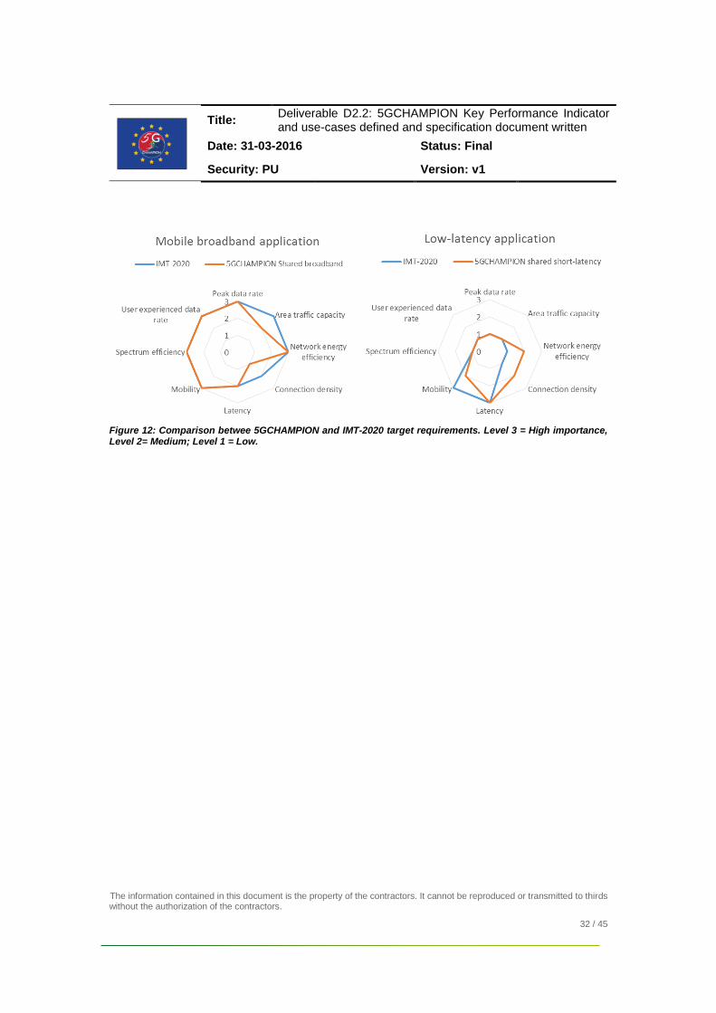
Figure 12 shows a comparison between the target requirements for the 5GCHAMPION application scenarios to be shown and the Olympics and the IMT-2020 requirements. Most of the levels are matched for both broadband and low-latency applications. However, due to interoperability between the systems, more effort is needed on the network level. Also, due to the lack of real 5G BS, mobility and connectivity are sacrificed for low-latency applications and mobile broadband applications, respectively.
Title: Deliverable D2.2: 5GCHAMPION Key Performance Indicator and use-cases defined and specification document written
Date: 31-03-2016 Status: Final
Security: PU Version: v1
The information contained in this document is the property of the contractors. It cannot be reproduced or transmitted to thirds without the authorization of the contractors.
32 / 45
Figure 12: Comparison betwee 5GCHAMPION and IMT-2020 target requirements. Level 3 = High importance, Level 2= Medium; Level 1 = Low.

Title: Deliverable D2.2: 5GCHAMPION Key Performance Indicator and use-cases defined and specification document written
Date: 31-03-2016 Status: Final
Security: PU Version: v1
The information contained in this document is the property of the contractors. It cannot be reproduced or transmitted to thirds without the authorization of the contractors.
33 / 45
7 5GCHAMPION testing scenarios
Figure 13: 5GCHAMPION system architecture.
The overall 5GCHAMPION system architecture is depicted in Figure 13 and it includes two different implementations of 5G networks, respectively, developed in Europe and Korea. Throughout NFV/SDN functionalities these networks can efficiently interoperate providing high end-to-end performance. In both 5G systems the core network includes vEPC and radio access via mmW backhaul. A detailed description of the architecture is provided in [1]. In the sequel we summarize the main technology requirements
Radio Access
Multiple access and advanced waveform technologies combined with advances in coding and modulation algorithms.
Advanced baseband computation is required to meet the complex requirements of new solutions like mass-scale MIMO.
10Gbit/s fibre or Ethernet connections on interfaces.
Advance integrated access node and backhaul design are required to enable the very dense networking of radio nodes.
Wireless backhaul in the higher frequency bands including mmW band (26.5 - 29.6 GHz in EU and 25.14 - 26.14 GHz in KR)
Maximum 800MHz bandwidth (EU) and 1GHz in KR
Array antennas and beamforming.
mmW and Satellite positioning combination to have more accurate position information.
Core network
Virtualized architecture which will provide on-demand resource processing, storage and network capacity wherever needed.
Technologies to enable more flexibility for the creation of new services and new applications.
Distributed data plane and centralized control plane.

Title: Deliverable D2.2: 5GCHAMPION Key Performance Indicator and use-cases defined and specification document written
Date: 31-03-2016 Status: Final
Security: PU Version: v1
The information contained in this document is the property of the contractors. It cannot be reproduced or transmitted to thirds without the authorization of the contractors.
34 / 45
7.1 Utilization of mmW backhaul in the 5GTN
Key facts
Use-case Wireless backhaul connecting heterogeneous radio access
Location University of Oulu, Finland
Type Stand-alone demo
Core network 5GTN core network
Carrier frequency ~27 GHz
Backhaul data-rate 2.5 Gbit/s
User-connectivity Wi-Fi, LTE
KPIs 100 Mbit/s user experience, heterogeneous access, SDN/NFV in EPC
Figure 14: Plan for multi-RAT connectivity via mmW backhaul in Oulu.
This testing scenario refers to use-case1. It consists of a live experience of a 5G test-network where users can connect with a SIM card to a local (5GTN exclusive) operator and benefit of free data-connection for internet-based services including web-browsing, video downloading/streaming, content sharing and IoT-based applications. In this live network, the 5GCHAMPION project will test the EU mmW backhaul as a high-capacity (2.5 Gbit/s) IP-traffic pipeline to connect multi-RAT hot-spot providing Wi-Fi and LTE access. The main objective is to demonstrate that by gathering 4G/WiFi traffic from several NodeB's/access points, then total bandwidth over a 5G link goes beyond existing 4G capacity.
A preliminary deployment plan is depicted in Figure 14, where the backhaul link is established between two mmW radio units, also referred to as backhaul radio unit (B-RU). The actual location of the B-RU, however, is yet to be determined. The environment characteristic is office-type, though indoor-to-outdoor links are likely to be used.
Connectivity to Korea 5G test-bed is also available for test intersystem interoperability.
Test description Target KPIs
Video downloading 100 Mbit/s user experience
Low-medium device density (based on the availability of mobile devices)
On-line gaming 100 Mbit/s user experience
10-50 ms latency Document co-creation from mobile stations
200 Mbit/s
10-50 ms latency IoT-based environment monitoring
Low-medium device density (based on available number of IoT devices)

Title: Deliverable D2.2: 5GCHAMPION Key Performance Indicator and use-cases defined and specification document written
Date: 31-03-2016 Status: Final
Security: PU Version: v1
The information contained in this document is the property of the contractors. It cannot be reproduced or transmitted to thirds without the authorization of the contractors.
35 / 45
7.2 Feasibility of ultra-high data rate 5G downlink
Key facts
Use-case Ultra-high data-rate 5G DL
Location University of Oulu, Finland
Type Stand-alone demo
Carrier frequency 10-30 GHz
KPI DL user-rate 20 Gbit/s
Figure 15: Testing scenario for 20Gbit/s
This testing scenario refers to use-case2. The radio link is based on transmission at high-carrier frequency (10-30 GHz). It connects two radio units which are identical from technology viewpoint, however, one acting and BS and the other as UE. As the final objective is to verify the feasibility of a data-rate larger or equal to 20Gbit/s, focus is on the link-level performance evaluation. Using the base-band specifications in [1], the 20Gbit/s KPI can be reached with the following configurations:
256QAM
Carrier components 8 4
Spatial layers 4 8
Channel bandwidth [MHz] 800 400
Distance (outdoor) [m] 58 78
Distance (indoor) [m] 9 17
Table 8 : Configuration for 20 Gbit/s. Outdoor path-loss coefficient 2.5. Indoor path-loss coeffient 2.8.
Test description Target KPI
Link-test evaluation in indoor environment Data-rate 20Gbit/s
Peak spectral efficiency 30bit/s/Hz
256QAM Constellation
Link-test evaluation in outdoor environment Data-rate 20Gbit/s
Peak spectral efficiency 30bit/s/Hz
256QAM Constellation

Title: Deliverable D2.2: 5GCHAMPION Key Performance Indicator and use-cases defined and specification document written
Date: 31-03-2016 Status: Final
Security: PU Version: v1
The information contained in this document is the property of the contractors. It cannot be reproduced or transmitted to thirds without the authorization of the contractors.
36 / 45
7.3 5G-GNSS positioning
Key facts
Use-case Indoor-outdoor positioning
Location University of Oulu, Finland
Type Stand-alone demo
Satellite system
Multiconstellation GNSS including Galileo
mmW link ~27 GHz
Server Telespazio
KPIs accurate positioning
GNSS-5G interoperability
Figure 16: Implementation of the positioning system.
This application scenario relates to use-case3. The interoperability between 5G mmW link and satellite positioning is demonstrated by implementing the system depicted in Figure 16. On the left hand side, the receiver contains the solution algorithms with RTK solution a mixed GNSS and 5G solutions and a solution with only one GNSS if the receiver clock can be accurately synchronized. On the right hand side is the server that delivers the information of the RTK solution and the LoS information needed by the algorithms using the 5G network.
The positioning test will be conducted in outdoor open sky and urban environment. Additionally, simulation based results will be shown to compare the practical and ideal implementation of 5G-GNSS positioning.
Testing environment Target KPIs
RTK positioning in outdoor open sky mean positioning error <1m
positioning error standard deviation < 10m
positioning availability > 95%
5G-mmW and satellite positioning in urban environment
mean positioning error <1m
positioning error standard deviation < 10m
positioning availability > 95%

Title: Deliverable D2.2: 5GCHAMPION Key Performance Indicator and use-cases defined and specification document written
Date: 31-03-2016 Status: Final
Security: PU Version: v1
The information contained in this document is the property of the contractors. It cannot be reproduced or transmitted to thirds without the authorization of the contractors.
37 / 45
7.4 Emulation of sub 6GHz satellite access with IoT devices
Key facts
Use-case Satellite connectivity with 5G IoT devices
Location University of Oulu, Finland
Type Stand-alone demo
Channel emulator
Frequency range 0.2 – 6GHz, bandwidth up to 125MHz, noise and inference modelling. Mobility modelling (Doppler).
UE NB-IoT
KPIs High user density, reliability, service continuity
5G-SatCOM interoperability
Figure 17: Proposed satellite testbed for NB-IOT.
This application scenario relates to use-case4. The seamless access to satellite, for IoT use-cases, through a 5G radio interface demonstrator will be based on CEA’s proprietary flexible and programmable platform and CEA channel emulator. A flexible implementation of the Narrow band IoT radio interface will be investigated with special care on link level performance evaluation.
Figure 18 : Overview of the hardware platform.
The hardware platform is based on a hybrid FPGA integrating programmable logic and an ARM processor and various interfaces. The combination of the FPGA and the ARM processor allows the easy deployment of embedded Linux and is well suited for software-defined radio implementation and rapid prototyping. Ethernet PHY/MAC (IPv6 compatible) is provided for easy LAN connectivity.
A specific daughterboard may be developed to address the satellite L-band or S-band using AD9361 module. AD9361 RF front end is a software tunable component across a wide frequency range (70MHz to 6.0 GHz) with a channel bandwidth from 200 kHz up to 56 MHz, including ADC/DAC.Experiments will be carried out to quantify performance through the CEA channel emulator. The CEA channel emulator has the following characteristics:
Frequency range 200MHz – 6GHz.

Title: Deliverable D2.2: 5GCHAMPION Key Performance Indicator and use-cases defined and specification document written
Date: 31-03-2016 Status: Final
Security: PU Version: v1
The information contained in this document is the property of the contractors. It cannot be reproduced or transmitted to thirds without the authorization of the contractors.
38 / 45
Bandwidth up to 125MHz.
Noise and inference modelling.
Mobility modelling (Doppler).
The channel emulator will be used to evaluate the radio interface through the emulation of transmissions over standardized channel models or scenario specific models that will be studied/developed in the context of the project.
Test description Target KPIs
Evaluation of 5G IoT waveforms over GEO satellite links
High device density
Long UE battery life (application dependent)
QoS (latency, packet loss rate, SNR, etc.) based on the application
Service continuity: transparent handover between terrestrial and satellite networks
Evaluation of 5G IoT waveforms over NGSO satellite links
High device density
Long UE battery life (application dependent)
QoS (latency, packet loss rate, SNR, etc) based on the application
Service continuity: transparent handover between terrestrial and satellite networks
7.5 Simulated-environment for high user-mobility
Key facts
Use-case High-user mobility
Location ETRI, Korea
Type Stand-alone demo
Simulation Simulation based on ray-tracing/3GPP and 5GCHAMPION channel model
Figure 19: Link-level simulation for high user-mobility.
This test scenario refers to use-case5. In order to validate the following KPIs for high user-mobility of 500km/h, a link-level simulation with proper high-speed train channel models will be conducted to evaluate the performance of the system in terms of mmW wireless backhaul data rate and user-experience data rate. Since a field trial at mobility of 500km/h is somewhat unrealistic as of now, the main purpose of the use-case is to validate the feasibility of the system in such a high-mobility through the following simulation.
The link-level simulator will be developed under the same parameters of the prototype system implemented for the demonstration during the 2018 PyeongChang Winter Olympics. The simulator can be also designed to provide a visualization of some target KPIs on a computer
LLS
(Transmitter)
Channel Model based on
Ray Tracing Simulator
(RTS)
Simulation Result
Validation
LLS
(Receiver)
3GPP Channel Model
Channel Model
Validation
ChannelLLS
Input
LLS
Output
Simulation
Parameter
Setting
Simulation
Results
Link-Level Simulator (LLS)
for HST Performance Evaluation
Title: Deliverable D2.2: 5GCHAMPION Key Performance Indicator and use-cases defined and specification document written
Date: 31-03-2016 Status: Final
Security: PU Version: v1
The information contained in this document is the property of the contractors. It cannot be reproduced or transmitted to thirds without the authorization of the contractors.
39 / 45
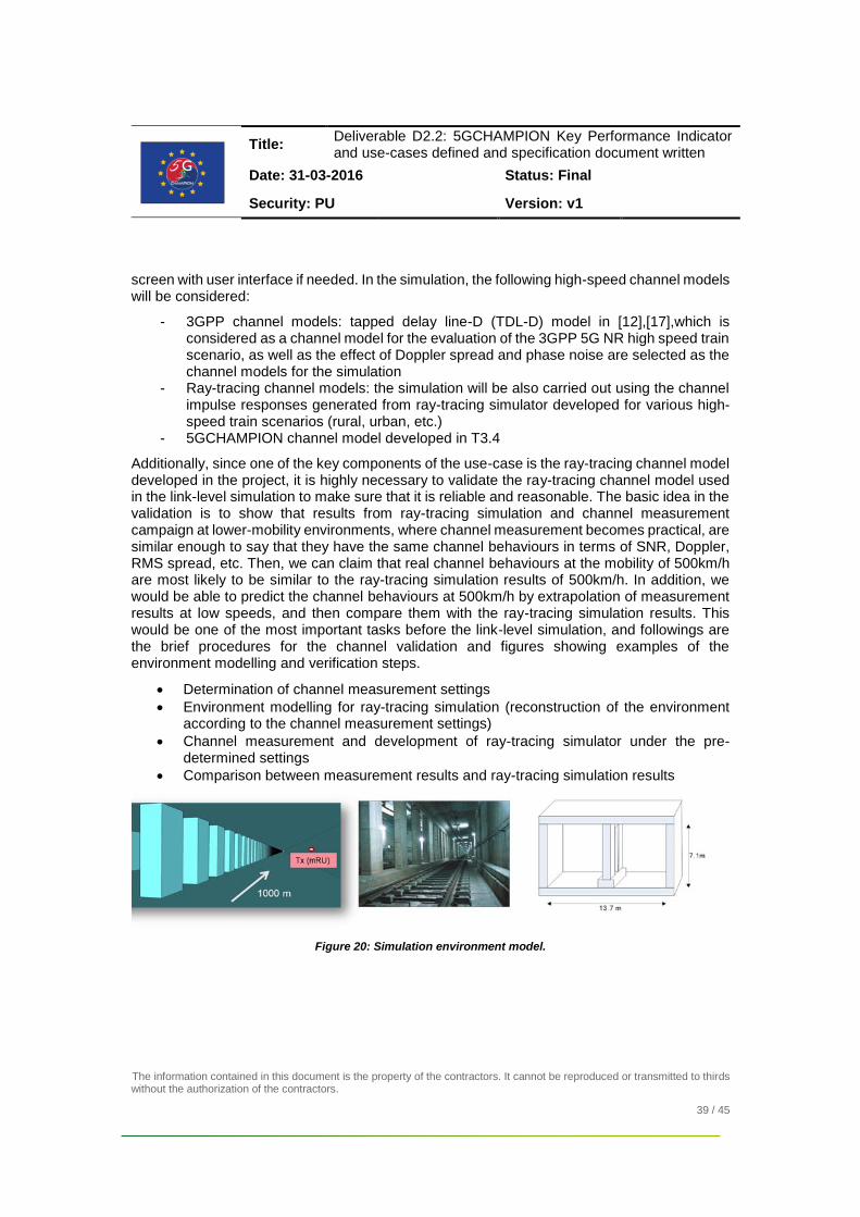
screen with user interface if needed. In the simulation, the following high-speed channel models will be considered:
- 3GPP channel models: tapped delay line-D (TDL-D) model in [12],[17],which is considered as a channel model for the evaluation of the 3GPP 5G NR high speed train scenario, as well as the effect of Doppler spread and phase noise are selected as the channel models for the simulation
- Ray-tracing channel models: the simulation will be also carried out using the channel impulse responses generated from ray-tracing simulator developed for various high-speed train scenarios (rural, urban, etc.)
- 5GCHAMPION channel model developed in T3.4
Additionally, since one of the key components of the use-case is the ray-tracing channel model developed in the project, it is highly necessary to validate the ray-tracing channel model used in the link-level simulation to make sure that it is reliable and reasonable. The basic idea in the validation is to show that results from ray-tracing simulation and channel measurement campaign at lower-mobility environments, where channel measurement becomes practical, are similar enough to say that they have the same channel behaviours in terms of SNR, Doppler, RMS spread, etc. Then, we can claim that real channel behaviours at the mobility of 500km/h are most likely to be similar to the ray-tracing simulation results of 500km/h. In addition, we would be able to predict the channel behaviours at 500km/h by extrapolation of measurement results at low speeds, and then compare them with the ray-tracing simulation results. This would be one of the most important tasks before the link-level simulation, and followings are the brief procedures for the channel validation and figures showing examples of the environment modelling and verification steps.
Determination of channel measurement settings
Environment modelling for ray-tracing simulation (reconstruction of the environment according to the channel measurement settings)
Channel measurement and development of ray-tracing simulator under the pre-determined settings
Comparison between measurement results and ray-tracing simulation results
Figure 20: Simulation environment model.
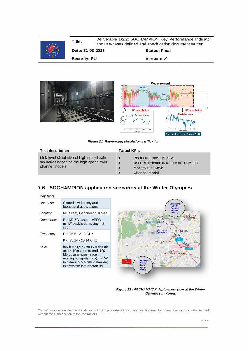
Title: Deliverable D2.2: 5GCHAMPION Key Performance Indicator and use-cases defined and specification document written
Date: 31-03-2016 Status: Final
Security: PU Version: v1
The information contained in this document is the property of the contractors. It cannot be reproduced or transmitted to thirds without the authorization of the contractors.
40 / 45
Figure 21: Ray-tracing simulation verification.
Test description Target KPIs
Link-level simulation of high-speed train scenarios based on the high-speed train channel models
Peak data-rate 2.5Gbit/s
User-experience data rate of 100Mbps
Mobility 500 Km/h
Channel model
7.6 5GCHAMPION application scenarios at the Winter Olympics
Key facts
Use-case Shared low-latency and broadband applications
Location IoT street, Gangneung, Korea
Components EU-KR 5G system: vEPC, mmW backhaul, moving hot-spot
Frequency EU: 26.5 - 27.3 GHz
KR: 25.14 - 26.14 GHz
KPIs low-latency: <2ms over-the-air and < 10ms end-to-end; 100 Mbit/s user-experience in moving hot-spots (bus); mmW backhaul: 2.5 Gbit/s data-rate; intersystem interoperability
Figure 22 : 5GCHAMPION deployment plan at the Winter Olympics in Korea.

Title: Deliverable D2.2: 5GCHAMPION Key Performance Indicator and use-cases defined and specification document written
Date: 31-03-2016 Status: Final
Security: PU Version: v1
The information contained in this document is the property of the contractors. It cannot be reproduced or transmitted to thirds without the authorization of the contractors.
41 / 45
At the Winter Olympics of Korea, the European and Korean 5G wireless backhaul testbeds will be deployed at the IoT street in the Gangneung Coastal Cluster (GCC) near to the Olympics venues. Figure 22 shows the details of the deployment plan. The typical environment is urban outdoor. The KR mmW test-beds will be used to connect a moving hot spot (Figure 23), whereas the EU mmW test-bed will be used for stationary link connectivity. As shown in the map, one EU and one KR unit will be co-located.
Figure 23: Experimental moving hot-spot.
This deployment constraint yields to coexistence issue, which requires attention. In fact, based on the frequency allocation discussed in Section 5, the two PoCs might interfere each other. Also, KT 5G system will use 28GHz band. Figure 24 shows the frequency plan for the 5GCHAMPION and KT 5G services.
Figure 24: Frequency allocation of the 5GCHAMPION PoCs.
This testing environment will serve both use-case 6 and use-case 7. More specifically, for use-case 6 we consider application scenarios with end-to-end latency no more than 10ms, of which 2ms is the target over-the-air. Candidate applications are VR on-line gaming and remote control, where the UEs (e.g., motion control for VR gaming) will interact in the same game, though connected to different radio access nodes.
As described in [D2.1], the low-latency requirement can be achieved by maintaining the user-plane functionality in the local (KR) EPC as well as by designing short radio frames for the mmW link.

Title: Deliverable D2.2: 5GCHAMPION Key Performance Indicator and use-cases defined and specification document written
Date: 31-03-2016 Status: Final
Security: PU Version: v1
The information contained in this document is the property of the contractors. It cannot be reproduced or transmitted to thirds without the authorization of the contractors.
42 / 45
With respect to use-case 7, candidate application scenario is the shared VR content or shared UHD (4k or 8k) video-streaming. As described in Section 4.9, two UEs (e.g., virtual glasses) will be connected to two different radio access and share the same content, which is provided either by a local cloud service in Korea or from data-source in Finland. UEs interaction is not expected, thus focus is on the data-rate and perceived user-experience. End-to-end latency can range between 50 and 300 ms, based on the content source location (maximum latency if source is in Finland). More specifically, it is targeted 2.5 Gbit/s data-rate over the mmW link as well as the 100Mbit/s user-experience in a stationary or moving hot-spot.
The following table summarizes the testing scenarios and corresponding target KPIs.
Test description Target KPIs
Shared low-latency use-case
remote gaming Intersystem interoperability
~2ms latency over the air
< 5ms E2E latency
SDN/NFV in vEPC
remote control Intersystem interoperability
~2ms latency over the air
< 10 ms E2E latency
SDN/NFV in vEPC
Shared broad-band application
Shared VR content Intersystem interoperability
100 Mbit/s user-experience
~ 50 ms E2E latency
>= 2.5 Gbit/s mmW wireless backhaul
SDN/NFV in vEPC
Shared UHD video/
3D content
Intersystem interoperability
100 Mbit/s user-experience
< 200 ms E2E latency
>= 2.5 Gbit/s mmW wireless backhaul
SDN/NFV in vEPC

Title: Deliverable D2.2: 5GCHAMPION Key Performance Indicator and use-cases defined and specification document written
Date: 31-03-2016 Status: Final
Security: PU Version: v1
The information contained in this document is the property of the contractors. It cannot be reproduced or transmitted to thirds without the authorization of the contractors.
43 / 45
8 References
[1] MiWEBA, “Definition of scenarios and use-cases,” ICT-608637 MiWEBA Deliverable D1.1, 2013 (available online http://www.miweba.eu/wp-content/uploads/2014/07/MiWEBA_D1.1_v1.0.pdf).
[2] MiWaves, “Definition of the heterogeneous network: topology, use-cases, and link budget,” ICT-619563 Deliverable D1.1.1, 2014.
[3] mmMagic, “Use-case characterization, KPIs and preferred suitable frequency ranges for future 5G systems between 6 GHz and 100 GHz,” ICT-67650 Deliverable D1.1, 2015 (available online https://bscw.5g-mmmagic.eu/pub/bscw.cgi/d54427/mmMAGIC_D1.1.pdf).
[4] 5GCHAMPION, “5G CHAMPION architecture, API- and interface document”, D2.1, 2017
[5] 5GPPP, 5G PPP use-cases and performance evaluation models, 2016 [6] ITU, Draft new Report ITU-R M.[IMT-2020.TECH PERF REQ] - Minimum requirements
related to technical performance for IMT-2020 radio interface(s), Feb. 2017 [7] ITU, ITU recommendation M.2083, September 2015 [8] SK Telecom 5G White Paper, “SK Telecom’s View on 5G Vision, Architecture,
Technology, and Spectrum” [9] http://www.lightpointe.com/4g---5g-mobile-backhaul-1.html [10] Ultra-Reliable and Low-Latency 5G Communication, EuCNC'16, Ericsson
2016 [11] A. Siligaris, F. Chaix, V. Puyal, J. Zevallos, L. Dussopt, and P. Vincent, “A low
power 60-GHz 2.2 Gbit/s UWB transceiver with integrated antennas for short range communications,” in Proc. 2013 IEEE Radio Frequency Integrated Circuit Symp. (RFIC 2013), Seattle, WA, USA, pp. 297-300, Jun. 2013.
[12] E. K. Smith, "Centimeter and millimeter wave attenuation and brightness temperature due to atmospheric oxygen and water vapor," in Radio Science, vol. 17, no. 06, pp. 1455-1464, Nov.-Dec. 1982.
[13] 3GPP TR 38.900, “Channel model for frequency spectrum above 6GHz,” v. 1.0.1, Jun. 2016.
[14] T. Jiang, et all, “Basestation 3-Dimensional Spatial Propagation Characteristics in Urban Microcell at 28 GHz”, EUCAP 2017
[15] T. S. Rappaport, G. R. MacCartney, M. K. Samimi, and S. Sun, “Wideband millimeter-wave propagation measurements and channel models for future wireless communication system design,” IEEE Trans. Communications, vol. 63, no. 9, pp. 3029-3056, Sept. 2015
[16] J. Ko, et. Al. “28 GHz Millimeter-Wave Measurements and Models for Signal Attenuation in Vegetated Areas”
[17] 3GPP, “Evaluation assumptions for the high speed train scenario for around 30GHz (RRH + relay) for NR,” R1-165979, May 2016.
[18] ETSI, “mmW Semiconductor Industry Technologies: Status and Evolution”, July 2016.
[19] EC Radio Spectrum Policy Group, “STRATEGIC ROADMAP TOWARDS 5G FOR EUROPE”, RSPG16-032 FINAL, November 2016.

Title: Deliverable D2.2: 5GCHAMPION Key Performance Indicator and use-cases defined and specification document written
Date: 31-03-2016 Status: Final
Security: PU Version: v1
The information contained in this document is the property of the contractors. It cannot be reproduced or transmitted to thirds without the authorization of the contractors.
44 / 45
[20] R. J. Weiler, M. Peter, W. Keusgen, K. Sakaguchi and F. Undi, "Environment Induced Shadowing of Urban Millimeter-Wave Access Links," in IEEE Wireless Communications Letters, vol. 5, no. 4, pp. 440-443, Aug. 2016.
[21] R. J. Weiler, M. Peter, W. Keusgen, A. Kortke and M. Wisotzki, "Millimeter-wave channel sounding of outdoor ground reflections," 2015 IEEE Radio and Wireless Symposium (RWS), San Diego, CA, 2015, pp. 95-97.
[22] H. Hashemi, X. Guan and A. Hajimiri, "A fully integrated 24 GHz 8-path phased-array receiver in silicon," Solid-State Circuits Conference, 2004. Digest of Technical Papers. ISSCC. 2004 IEEE International, 2004, pp. 390-534.
[23] A. Natarajan, A. Komijani and A. Hajimiri, "A fully integrated 24-GHz phased-array transmitter in CMOS," in IEEE Journal of Solid-State Circuits, vol. 40, no. 12, pp. 2502-2514, Dec. 2005.
[24] A. Babakhani, X. Guan, A. Komijani, A. Natarajan and A. Hajimiri, "A 77GHz 4-Element Phased Array Receiver with On-Chip Dipole Antennas in Silicon," 2006 IEEE International Solid State Circuits Conference - Digest of Technical Papers, San Francisco, CA, 2006, pp. 629-638.
[25] A. Natarajan, A. Komijani, X. Guan, A. Babakhani, Y. Wang and A. Hajimiri, "A 77GHz Phased-Array Transmitter with Local LO-Path Phase-Shifting in Silicon," 2006 IEEE International Solid State Circuits Conference - Digest of Technical Papers, San Francisco, CA, 2006, pp. 639-648.
[26] H. Krishnaswamy and H. Hashemi, "A Fully Integrated 24GHz 4-Channel Phased-Array Transceiver in 0.13μm CMOS Based on a Variable-Phase Ring Oscillator and PLL Architecture," 2007 IEEE International Solid-State Circuits Conference. Digest of Technical Papers, San Francisco, CA, 2007, pp. 124-591.
[27] T. Yu and G. M. Rebeiz, "A 22–24 GHz 4-Element CMOS Phased Array With On-Chip Coupling Characterization," in IEEE Journal of Solid-State Circuits, vol. 43, no. 9, pp. 2134-2143, Sept. 2008.
[28] A. Valdes-Garcia et al., "A Fully Integrated 16-Element Phased-Array Transmitter in SiGe BiCMOS for 60-GHz Communications," in IEEE Journal of Solid-State Circuits, vol. 45, no. 12, pp. 2757-2773, Dec. 2010.
[29] A. Natarajan et al., "A Fully-Integrated 16-Element Phased-Array Receiver in SiGe BiCMOS for 60-GHz Communications," in IEEE Journal of Solid-State Circuits, vol. 46, no. 5, pp. 1059-1075, May 2011.
[30] S. Emami et al., "A 60GHz CMOS phased-array transceiver pair for multi-Gb/s wireless communications," 2011 IEEE International Solid-State Circuits Conference, San Francisco, CA, 2011, pp. 164-166.
[31] M. Tabesh et al., "A 65nm CMOS 4-element Sub-34mW/element 60GHz phased-array transceiver," 2011 IEEE International Solid-State Circuits Conference, San Francisco, CA, 2011, pp. 166-168.
[32] M. Boers et al., "20.2 A 16TX/16RX 60GHz 802.11ad chipset with single coaxial interface and polarization diversity," 2014 IEEE International Solid-State Circuits Conference Digest of Technical Papers (ISSCC), San Francisco, CA, 2014, pp. 344-345.
[33] G. Mangraviti et al., "13.5 A 4-antenna-path beamforming transceiver for 60GHz multi-Gb/s communication in 28nm CMOS," 2016 IEEE International

Title: Deliverable D2.2: 5GCHAMPION Key Performance Indicator and use-cases defined and specification document written
Date: 31-03-2016 Status: Final
Security: PU Version: v1
The information contained in this document is the property of the contractors. It cannot be reproduced or transmitted to thirds without the authorization of the contractors.
45 / 45
Solid-State Circuits Conference (ISSCC), San Francisco, CA, 2016, pp. 246-247.
[34] S. Zihir, O. D. Gurbuz, A. Karroy, S. Raman and G. M. Rebeiz, "A 60 GHz single-chip 256-element wafer-scale phased array with EIRP of 45 dBm using sub-reticle stitching," Radio Frequency Integrated Circuits Symposium (RFIC), 2015 IEEE, Phoenix, AZ, 2015, pp. 23-26.
[35] B. Sadhu et al., " A 28GHz 32-Element Phased-Array Transceiver IC with Concurrent Dual Polarized Beams and 1.4 Degree Beam-Steering Resolution for 5G Communication," 2017 IEEE International Solid-State Circuits Conference (ISSCC), San Francisco, CA, 2017, pp. 128-129.
[36] S. Y. Mortazavi and K. J. Koh, "A 38 GHz inverse class-F power amplifier with 38.5% peak PAE, 16.5 dB gain, and 50 mW Psat in 0.13-µm SiGe BiCMOS," Radio Frequency Integrated Circuits Symposium (RFIC), 2015 IEEE, Phoenix, AZ, 2015, pp. 211-214.
[37] C. R. Chappidi and K. Sengupta, "A frequency-reconfigurable mm-Wave power amplifier with active-impedance synthesis in an asymmetrical non-isolated combiner," 2016 IEEE International Solid-State Circuits Conference (ISSCC), San Francisco, CA, 2016, pp. 344-345.
[38] S. Shakib, H. C. Park, J. Dunworth, V. Aparin and K. Entesari, "20.6 A 28GHz efficient linear power amplifier for 5G phased arrays in 28nm bulk CMOS," 2016 IEEE International Solid-State Circuits Conference (ISSCC), San Francisco, CA, 2016, pp. 352-353.
[39] K. Fujii, "Low cost Ka-band 7W GaAs PHEMT based HPA with GaN PHEMT equivalent performance," Radio Frequency Integrated Circuits Symposium (RFIC), 2015 IEEE, Phoenix, AZ, 2015, pp. 207-210.
[40] K. Datta and H. Hashemi, "2.9 A 29dBm 18.5% peak PAE mm-Wave digital power amplifier with dynamic load modulation," 2015 IEEE International Solid-State Circuits Conference - (ISSCC) Digest of Technical Papers, San Francisco, CA, 2015, pp. 1-3.
[41] B. Hanafi, O. Gürbüz, H. Dabag, J. F. Buckwalter, G. Rebeiz and P. Asbeck, "Q-Band Spatially Combined Power Amplifier Arrays in 45-nm CMOS SOI," in IEEE Transactions on Microwave Theory and Techniques, vol. 63, no. 6, pp. 1937-1950, June 2015.
[42] I. Sarkas, A. Balteanu, E. Dacquay, A. Tomkins and S. Voinigescu, "A 45nm SOI CMOS Class-D mm-Wave PA with >10Vpp differential swing," 2012 IEEE International Solid-State Circuits Conference, San Francisco, CA, 2012, pp. 88-90.
[43] Y. Qi, et al, Quantifying data rate and bandwidth requirements for immersive 5G experience," 2016 IEEE International Conference on Communications Workshops (ICC), Kuala Lumpur, 2016, pp. 455-461.
[44] Huwaei, “Whitepaper on the VR-Oriented Bearer Network Requirements”, Issue 01, September 2016.