Embed Size (px)
Citation preview
FP7-2011-ICT-GC
Duration: 36 months
SMART-LIC – Smart and Compact Battery Management System Module for Integration into Lithium-Ion Cell for Fully Electric Vehicles
Dissemination level PU Public X PP Restricted to other programme participants (including the Commission Services) RE Restricted to a group specified by the consortium (including the Commission Services) CO Confidential, only for members of the consortium (including the Commission Services)
GREENCAR – SMART-LIC Project
Deliverable 1.1
Report on WP1
Report detailing System Specification & Requirements
Revision: 1 .8 final (v. 1.8) Due date: 31-12-2011 (m8) Actual submission date: 31-01-2012 Lead partner: Centro Ricerche Fiat
Smart-LIC ● D1.1 31.01.2012 Page 1 of 56
1 of 56 [Public
Summary
No and name D1.1 Report detailing System Specification
& Requirements
Status Working (in progress) Due M8 Date 31-01-2012 Author(s) Gianfranco Burzio, Daniela Parena
Editor Gianfranco Burzio DoW Report detailing system specification & requirements:
- Definition of characteristic application scenarios and deduction of the over-all system requirements;
- Specification of cell balancing strategy, of requirements for the communication /EMC and for the integration /packaging solutions.
Comments Document history V Date Author Description
0.1 19-10-2011 G. Burzio First draft 0.2 02-11-2011 D. Parena Second draft 0.3 08-11-2011 G. Burzio, D. Parena Third draft
0.4 06-12-2011 D. Parena Draft v.4 including interesting parameters to be taken into account
0.5 07-12-2011 G. Burzio, D. Parena Draft v.5 including updates following review of 30/11/2011
0.6 19-12-2011 G. Burzio, D. Parena Revision 0.7 17-01-2012 G. Burzio, D. Parena Micro-vett contribution integrated
0.8 19-01-2012 G. Burzio, D. Parena Continental contribution (+Micro-vett) and ST remarks integrated
0.9 24-01-2012 G. Burzio, D. Parena ST (Bison) contribution updated ENAC (Mager) contribution integrated
1.0 24-01-2012 G. Burzio, D. Parena General revision 1.1 25-01-2012 G. Burzio General revision 1.2 26-01-2012 G. Burzio, D. Parena General revision 1.3 30-01-2012 G. Burzio, D. Parena Conclusions
1.4 30-01-2012 G. Burzio General revision – Dissemination level: public - Conclusions
1.5 31-1-2012 G. Burzio,D. Parena Final revision after Conference Call discussion 1.6 06-02-2012 G. Burzio,D. Parena Feedback from STMicroelectronics 1.7 07-02-2012 G. Burzio,D. Parena Final version for Peer Review 1.8 07-02-2012 G. Burzio,D. Parena Final version for Peer Review Disclaimer The information in this document is provided as is and no guarantee or warranty is given that the information is fit for any particular purpose. The user thereof uses the information at its sole risk and liability. The document reflects only the author’s views and the ENIAC Joint Undertaking is not liable for any use that may be made of the information contained therein.
Smart-LIC ● D1.1 31.01.2012 Page 2 of 56
2 of 56 [Public
Table of contents
1 Acronyms ..................................................................................................... 6
2 Scope ............................................................................................................. 8
3 Executive Summary .................................................................................. 10 3.1 Publishable summary ......................................................................................................... 10 3.2 Non-publishable information ............................................................................................. 10
4 WP 1 – Definition of Concept and Requirements .................................. 11 4.1 WP1 structure: contributions & collaborations .................................................................. 11 4.2 Relations to other activities in the project .......................................................................... 12
5 Application scenarios of Battery Systems in FEVs ................................ 14 5.1 Application Scenario - Vehicle Types ............................................................................... 14
5.1.1 Identified Parameters ......................................................................................................... 15 5.1.2 Current BMS and balancing solutions .............................................................................. 29 5.1.3 Review of existing SiP and module integration solutions ................................................ 33 5.1.4 Options for communication systems ................................................................................. 34
5.2 High Voltage Battery management .................................................................................... 37
6 System Requirements capture ................................................................. 39 6.1 Application context ............................................................................................................ 39 6.2 Questionnaire ..................................................................................................................... 39 6.3 Requirements definition: questionnaire analysis ............................................................... 41
6.3.1 Questionnaire results ......................................................................................................... 41 6.3.1 Packaging and integration requirements ........................................................................... 42 6.3.2 Safety requirements - ASIL according to ISO26262 ........................................................ 43
7 Systems Specifications .............................................................................. 45 7.1 Electrical specification ....................................................................................................... 45 7.2 Mechanical requirements for the smart battery architecture .............................................. 46
7.2.1 Environmental conditions .................................................................................................. 46 7.3 BMS (Battery Management System) ................................................................................. 47
7.3.1 Functions ............................................................................................................................ 47 7.3.2 BMS outcomes .................................................................................................................. 48 7.3.3 Communication protocol ................................................................................................... 50 7.3.4 Communication interface .................................................................................................. 50 7.3.5 EMC ................................................................................................................................... 50 7.3.6 Connectivity (mechanical / electrical) .............................................................................. 50 7.3.7 Temperature requirements (which voltage at what temperature?) ................................... 50 7.3.8 Memory requirements (what shall be stored / how long / for which purpose?) .............. 51 7.3.9 Black box (stored data, how long?) ................................................................................... 51 7.3.10 Cryptography ..................................................................................................................... 51
8 Conclusions ................................................................................................ 53 8.1 Contribution to overall picture ........................................................................................... 53 8.2 Relation to the state-of-the-art and progress beyond it ...................................................... 53

Smart-LIC ● D1.1 31.01.2012 Page 3 of 56
3 of 56 [Public
8.3 Impacts to other WPs and Tasks ........................................................................................ 54 8.4 Contribution to demonstration (what aspects of the work that will be demonstrated ........ 54 8.5 Other conclusions and lessons learned .............................................................................. 54
9 References .................................................................................................. 55
Smart-LIC ● D1.1 31.01.2012 Page 4 of 56
4 of 56 [Public
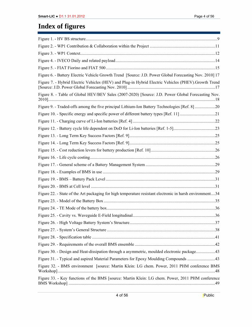
Index of figures Figure 1. - HV BS structure ...........................................................................................................................9
Figure 2. - WP1 Contribution & Collaboration within the Project ............................................................. 11
Figure 3. - WP1 Context.............................................................................................................................. 12
Figure 4. - IVECO Daily and related payload ............................................................................................. 14
Figure 5. - FIAT Fiorino and FIAT 500 ...................................................................................................... 15
Figure 6. - Battery Electric Vehicle Growth Trend [Source: J.D. Power Global Forecasting Nov. 2010] 17
Figure 7. - Hybrid Electric Vehicles (HEV) and Plug-in Hybrid Electric Vehicles (PHEV).Growth Trend [Source: J.D. Power Global Forecasting Nov. 2010] .................................................................................. 17
Figure 8. - Table of Global HEV/BEV Sales (2007-2020) [Source: J.D. Power Global Forecasting Nov. 2010]............................................................................................................................................................ 18
Figure 9. - Traded-offs among the five principal Lithium-Ion Battery Technologies [Ref. 8] ................... 20
Figure 10. - Specific energy and specific power of different battery types [Ref. 11] ................................. 21
Figure 11. - Charging curve of Li-Ion batteries [Ref. 4] ............................................................................. 22
Figure 12. - Battery cycle life dependent on DoD for Li-Ion batteries [Ref. 1-5] ....................................... 23
Figure 13. - Long Term Key Success Factors [Ref. 9] ................................................................................ 25
Figure 14. - Long Term Key Success Factors [Ref. 9] ................................................................................ 25
Figure 15. - Cost reduction levers for battery production [Ref. 10] ............................................................ 26
Figure 16. - Life cycle costing ..................................................................................................................... 26
Figure 17. - General scheme of a Battery Management System ................................................................. 29
Figure 18. - Examples of BMS in use ......................................................................................................... 29
Figure 19. - BMS – Battery Pack Level ...................................................................................................... 31
Figure 20. - BMS at Cell level .................................................................................................................... 31
Figure 22. - State of the Art packaging for high temperature resistant electronic in harsh environment .... 34
Figure 23. - Model of the Battery Box ........................................................................................................ 35
Figure 24. - TE Mode of the battery box ..................................................................................................... 36
Figure 25. - Cavity vs. Waveguide E-Field longitudinal ............................................................................. 36
Figure 26. - High Voltage Battery System’s Structure ................................................................................ 37
Figure 27. - System’s General Structure ..................................................................................................... 38
Figure 28. - Specification table ................................................................................................................... 41
Figure 29. - Requirements of the overall BMS ensemble ........................................................................... 42
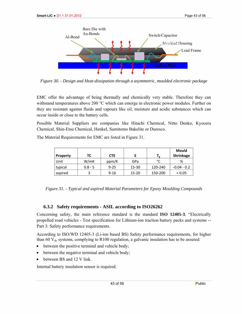
Figure 30. - Design and Heat-dissipation through a asymmetric, moulded electronic package.................. 43
Figure 31. - Typical and aspired Material Parameters for Epoxy Moulding Compounds .......................... 43
Figure 32. - BMS environment [source: Martin Klein: LG chem. Power, 2011 PHM conference BMS Workshop] ................................................................................................................................................... 48
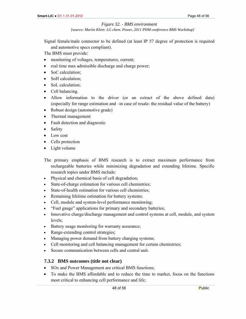
Figure 33. - Key functions of the BMS [source: Martin Klein: LG chem. Power, 2011 PHM conference BMS Workshop] ......................................................................................................................................... 49

Smart-LIC ● D1.1 31.01.2012 Page 5 of 56
5 of 56 [Public
Figure 34. - BMS design strategies [source: Martin Klein: LG chem. Power 2011, PHM conference BMS Workshop] ................................................................................................................................................... 50
Figure 35. - Software tasks [source: Martin Klein: LG chem. Power 2011, PHM conference BMS Workshop] ................................................................................................................................................... 52
Smart-LIC ● D1.1 31.01.2012 Page 6 of 56
6 of 56 [Public
1 ACRONYMS
BEV Battery Electric Vehicle BMS Battery Management System BoL Beginning of Life BoM Bill of materials BP Battery Pack BS Battery System CS Cooling System CTE Coefficient of Thermal Expansion DoD Depth of Discharge E Elastic Modulus EIS Electrochemical Impedance Spectroscopy EMC Epoxy Moulding Compound EMF ??? EoL End of Life EPI Electric Power Interface FEV Full Electric Vehicle HV High Voltage LDV Light Delivery Vehicle LTCC Low Temperature Cofired Ceramic NEDC New European Driving Cycle o.s.l. over sea level PA66 Polyamide 66 PBT Polybutylene Terephthalate PLC Power Line Communication PHEV Plug-in Electric vehicles PI Power Integrity RFID Radio Frequency IDentification SI Signal Integrity SiP System-in-Package SoC State of Charge SoF State of Function SoH State of Health SoL State of Life TC Thermal Conductivity Tg Glass Transition Temperature

Smart-LIC ● D1.1 31.01.2012 Page 7 of 56
7 of 56 [Public
VMU Vehicle management System

Smart-LIC ● D1.1 31.01.2012 Page 8 of 56
8 of 56 [Public
2 SCOPE
The SMART-LIC Project addresses the development of a new Battery Management System (BMS) concept aiming at:
• Lower system complexity by a radical reduction of wiring and connectors, cause of- EMF emissions and major source of malfunctions.
• Higher efficiency of the battery packs because of the local control.
• Increased overall reliability such that failures would be determined by battery cells rather than by electronics and wiring connectors.
• Increased flexibility of the overall energy-power routing such to assure that all cells could perform at their maximum rating independently from the rating of the others.
• Radical overall cost reduction of the overall BMS because of reduced cabling and connectors as well as simplification of the electronics.
• Increased precision in determining the states of charge, of health, and of function of the individual cells and of the entire battery by applying a new cell / battery model, based on electrochemical impedance spectroscopy (EIS).
• Reduced maintenance of the battery packs assured by the monitoring of the single cell (macro cell) with the possibility to switch it off from the rest of the pack.
• Reduced cost of ownership for the end user due a significant increase in battery lifetime caused by the improved management on cell level.
This Report details system specification and requirements through the definition of characteristic application scenarios and deduction of the over-all system requirements.
In details the system will consist of: • Battery Pack (cells, cabling, fuses, contactors…); • integrated cooling system; • BMS master and slave boards with CAN-bus interface; • Battery System housing with fixing parts.
Electric and electronic components: • connectors IP57 or higher/lower depending….?; • voltage, current and temperature sensors; • insulation detection via BMS; • additional electric devices like precharge contactors and main rapid fuses (for both poles).
Smart-LIC ● D1.1 31.01.2012 Page 9 of 56
9 of 56 [Public
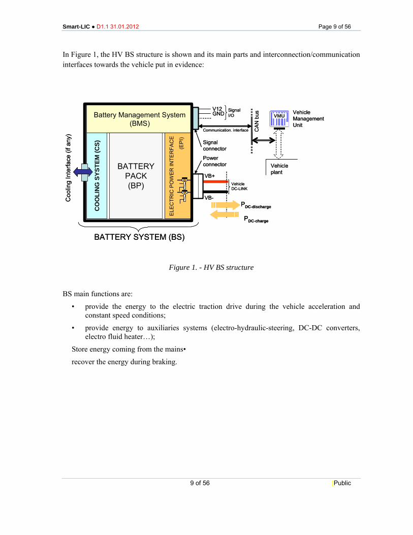
In Figure 1, the HV BS structure is shown and its main parts and interconnection/communication interfaces towards the vehicle put in evidence:
Figure 1. - HV BS structure
BS main functions are:
• provide the energy to the electric traction drive during the vehicle acceleration and constant speed conditions;
• provide energy to auxiliaries systems (electro-hydraulic-steering, DC-DC converters, electro fluid heater…);
Store energy coming from the mains•
recover the energy during braking.
BATTERYPACK(BP)
Battery Management System(BMS)
CO
OLI
NG
SYS
TEM
(CS)
Powerconnector
Signalconnector
V12GND
SignalI/O
VB+
VB-
VehicleDC-LINK
VMU
CAN
bus
PDC-discharge
Vehicleplant
PDC-charge
ELE
CTR
IC P
OW
ER IN
TER
FAC
E
VehicleManagementUnit
Communication. interface
BATTERY SYSTEM (BS)
(EP
I)
Coo
ling
Inte
rface
(if a
ny)
BATTERYPACK(BP)
Battery Management System(BMS)
CO
OLI
NG
SYS
TEM
(CS)
Powerconnector
Signalconnector
V12GND
SignalI/O
VB+
VB-
VehicleDC-LINK
VMUVMU
CAN
bus
PDC-discharge
Vehicleplant
PDC-charge
ELE
CTR
IC P
OW
ER IN
TER
FAC
E
VehicleManagementUnit
Communication. interface
BATTERY SYSTEM (BS)
(EP
I)
Coo
ling
Inte
rface
(if a
ny)
Smart-LIC ● D1.1 31.01.2012 Page 10 of 56
10 of 56 [Public
3 EXECUTIVE SUMMARY
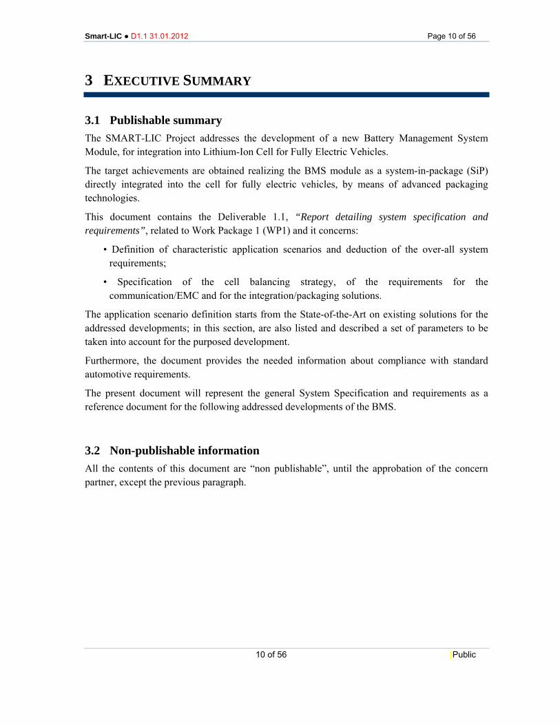
3.1 Publishable summary The SMART-LIC Project addresses the development of a new Battery Management System Module, for integration into Lithium-Ion Cell for Fully Electric Vehicles.
The target achievements are obtained realizing the BMS module as a system-in-package (SiP) directly integrated into the cell for fully electric vehicles, by means of advanced packaging technologies.
This document contains the Deliverable 1.1, “Report detailing system specification and requirements”, related to Work Package 1 (WP1) and it concerns:
• Definition of characteristic application scenarios and deduction of the over-all system requirements;
• Specification of the cell balancing strategy, of the requirements for the communication/EMC and for the integration/packaging solutions.
The application scenario definition starts from the State-of-the-Art on existing solutions for the addressed developments; in this section, are also listed and described a set of parameters to be taken into account for the purposed development.
Furthermore, the document provides the needed information about compliance with standard automotive requirements.
The present document will represent the general System Specification and requirements as a reference document for the following addressed developments of the BMS.
3.2 Non-publishable information All the contents of this document are “non publishable”, until the approbation of the concern partner, except the previous paragraph.
Smart-LIC ● D1.1 31.01.2012 Page 11 of 56
11 of 56 [Public
4 WP 1 – DEFINITION OF CONCEPT AND REQUIREMENTS
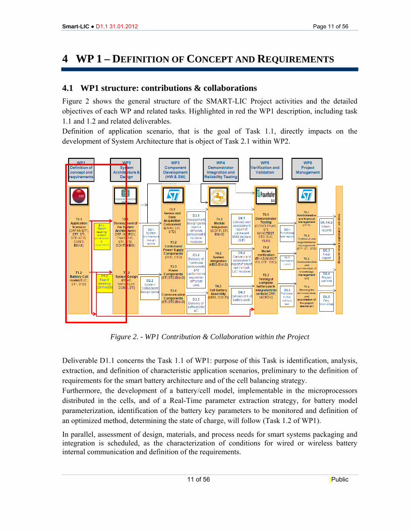
4.1 WP1 structure: contributions & collaborations Figure 2 shows the general structure of the SMART-LIC Project activities and the detailed objectives of each WP and related tasks. Highlighted in red the WP1 description, including task 1.1 and 1.2 and related deliverables. Definition of application scenario, that is the goal of Task 1.1, directly impacts on the development of System Architecture that is object of Task 2.1 within WP2.
Figure 2. - WP1 Contribution & Collaboration within the Project
Deliverable D1.1 concerns the Task 1.1 of WP1: purpose of this Task is identification, analysis, extraction, and definition of characteristic application scenarios, preliminary to the definition of requirements for the smart battery architecture and of the cell balancing strategy. Furthermore, the development of a battery/cell model, implementable in the microprocessors distributed in the cells, and of a Real-Time parameter extraction strategy, for battery model parameterization, identification of the battery key parameters to be monitored and definition of an optimized method, determining the state of charge, will follow (Task 1.2 of WP1).
In parallel, assessment of design, materials, and process needs for smart systems packaging and integration is scheduled, as the characterization of conditions for wired or wireless battery internal communication and definition of the requirements.
Smart-LIC ● D1.1 31.01.2012 Page 12 of 56
12 of 56 [Public
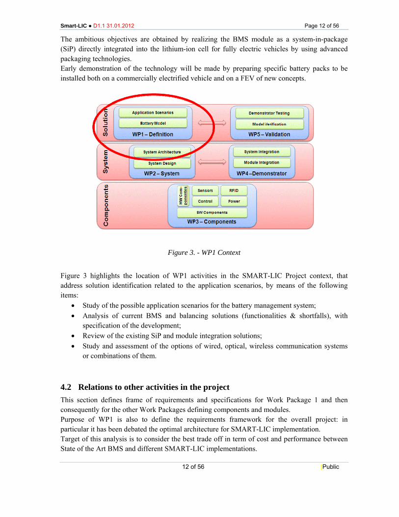
The ambitious objectives are obtained by realizing the BMS module as a system-in-package (SiP) directly integrated into the lithium-ion cell for fully electric vehicles by using advanced packaging technologies. Early demonstration of the technology will be made by preparing specific battery packs to be installed both on a commercially electrified vehicle and on a FEV of new concepts.
Figure 3. - WP1 Context
Figure 3 highlights the location of WP1 activities in the SMART-LIC Project context, that address solution identification related to the application scenarios, by means of the following items:
• Study of the possible application scenarios for the battery management system; • Analysis of current BMS and balancing solutions (functionalities & shortfalls), with
specification of the development; • Review of the existing SiP and module integration solutions; • Study and assessment of the options of wired, optical, wireless communication systems
or combinations of them.
4.2 Relations to other activities in the project This section defines frame of requirements and specifications for Work Package 1 and then consequently for the other Work Packages defining components and modules. Purpose of WP1 is also to define the requirements framework for the overall project: in particular it has been debated the optimal architecture for SMART-LIC implementation. Target of this analysis is to consider the best trade off in term of cost and performance between State of the Art BMS and different SMART-LIC implementations.
Smart-LIC ● D1.1 31.01.2012 Page 13 of 56
13 of 56 [Public
The following parameters have been considered to carry on this analysis:
1) Life time of the battery (with and w/o SMART-LIC);
2) Battery cost (with and w/o SMART-LIC);
3) Efficiency and losses of module (with and w/o SMART-LIC).
First point of this analysis is the identification of the optimal granularity of the SMART-LIC module defined as the number of lithium-ion cell integrated in the single module. Introducing a BMS module at Cell Level provides more accurate SoH and SoC monitoring, enabling higher performances in term of Life Time and reducing the maintenance cost but introduces also some drawbacks in term of higher BoM and Efficiency/Losses. The analysis will be completed inside WP2.
Smart-LI
5 AP
5.1 AFIAT foparticulovercomavailabloverall w
For this
Au• 9Ma• VMa• =
In its stbattery pFor reqElectricBattery
C ● D1.1 31.0
PPLICAT
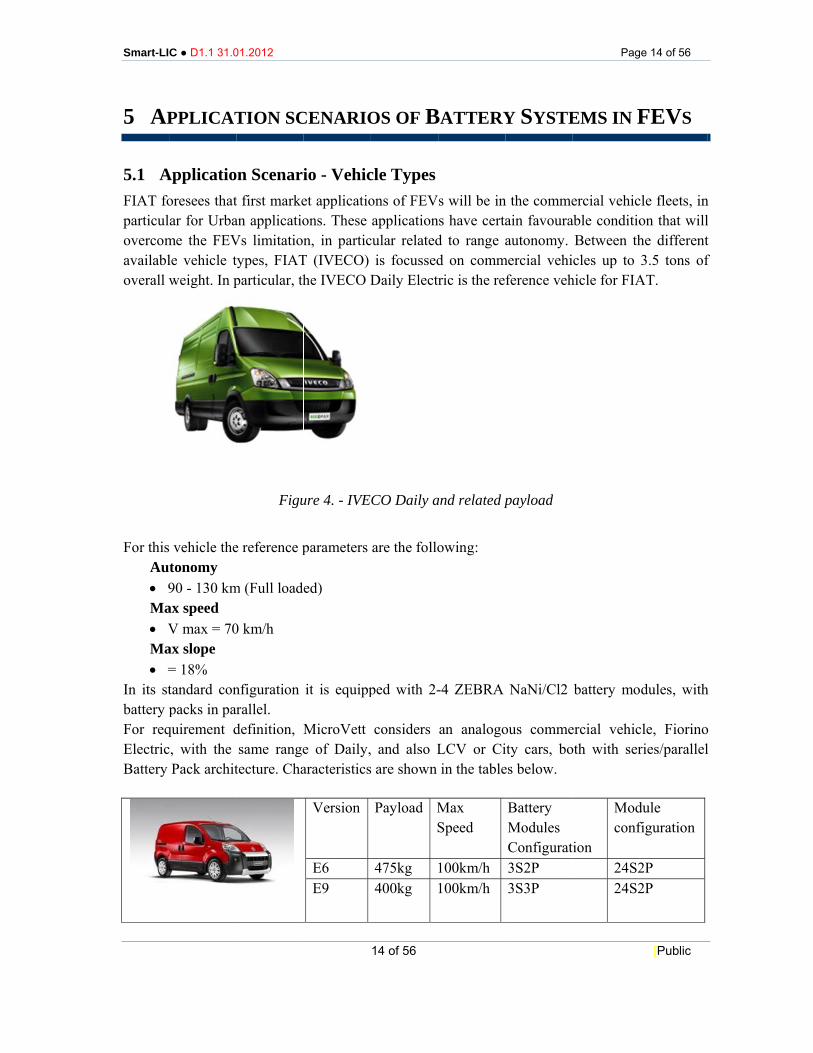
Applicatiooresees thatar for Urba
me the FEVle vehicle tweight. In p
s vehicle thetonomy 90 - 130 kmax speed V max = 70ax slope = 18% tandard conpacks in par
quirement dc, with the
Pack archit
01.2012
TION SC
on Scenarit first markean applicatioVs limitationtypes, FIATparticular, th
Figu
e reference p
m (Full load
0 km/h
nfiguration rallel. definition, Msame range
tecture. Cha
CENARIO
io - Vehicet applicatioons. These n, in partic
T (IVECO) he IVECO D
ure 4. - IVE
parameters
ed)
it is equipp
MicroVette of Daily,aracteristics
Version
E6 E9
14 of 56
OS OF B
cle Typesons of FEVapplication
cular relatedis focussed
Daily Electr
CO Daily a
are the follo
ped with 2-
considers and also L
s are shown
Payload MS
475kg 400kg
BATTERY
s will be inns have certad to range ad on commric is the re
and related p
owing:
-4 ZEBRA
an analogoLCV or Ciin the table
Max Speed
100km/h 100km/h
Y SYSTE
n the commeain favouraautonomy.
mercial vehiference veh
payload
NaNi/Cl2
ous commeity cars, boes below.
Battery Modules Configurat3S2P 3S3P
Pag
EMS IN F
ercial vehicable conditio
Between thcles up to
hicle for FIA
battery mo
ercial vehicoth with ser
ion
Modconf
24S224S2
e 14 of 56
[Public
FEVS
cle fleets, inon that willhe different3.5 tons of
AT.
odules, with
cle, Fiorinories/parallel
dule figuration
2P 2P
n l t f
h
o l
Smart-LIC ● D1.1 31.01.2012 Page 15 of 56
15 of 56 [Public
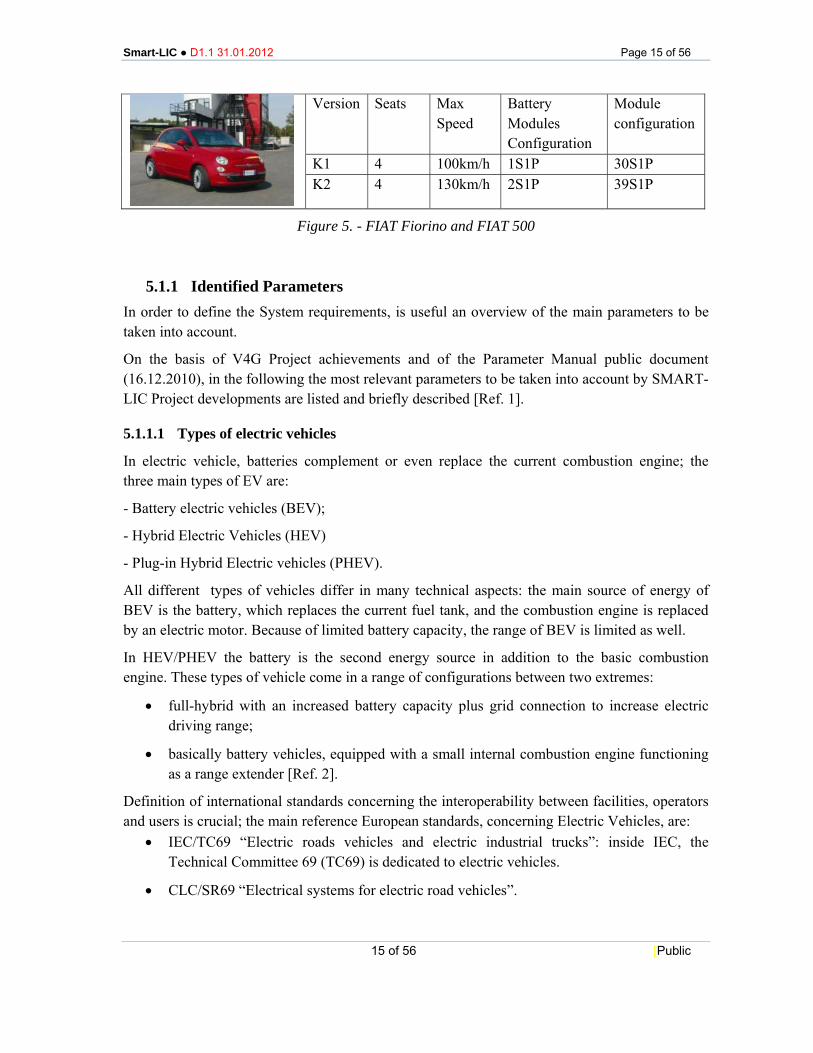
Figure 5. - FIAT Fiorino and FIAT 500
5.1.1 Identified Parameters In order to define the System requirements, is useful an overview of the main parameters to be taken into account.
On the basis of V4G Project achievements and of the Parameter Manual public document (16.12.2010), in the following the most relevant parameters to be taken into account by SMART-LIC Project developments are listed and briefly described [Ref. 1].
5.1.1.1 Types of electric vehicles
In electric vehicle, batteries complement or even replace the current combustion engine; the three main types of EV are:
- Battery electric vehicles (BEV);
- Hybrid Electric Vehicles (HEV)
- Plug-in Hybrid Electric vehicles (PHEV).
All different types of vehicles differ in many technical aspects: the main source of energy of BEV is the battery, which replaces the current fuel tank, and the combustion engine is replaced by an electric motor. Because of limited battery capacity, the range of BEV is limited as well.
In HEV/PHEV the battery is the second energy source in addition to the basic combustion engine. These types of vehicle come in a range of configurations between two extremes:
• full-hybrid with an increased battery capacity plus grid connection to increase electric driving range;
• basically battery vehicles, equipped with a small internal combustion engine functioning as a range extender [Ref. 2].
Definition of international standards concerning the interoperability between facilities, operators and users is crucial; the main reference European standards, concerning Electric Vehicles, are:
• IEC/TC69 “Electric roads vehicles and electric industrial trucks”: inside IEC, the Technical Committee 69 (TC69) is dedicated to electric vehicles.
• CLC/SR69 “Electrical systems for electric road vehicles”.
Version Seats Max Speed
Battery Modules Configuration
Module configuration
K1 4 100km/h 1S1P 30S1P K2 4 130km/h 2S1P 39S1P
Smart-LIC ● D1.1 31.01.2012 Page 16 of 56
16 of 56 [Public
5.1.1.2 Consumption
The consumption evaluates the amount of energy needed from EV (PHEV) to drive 1 km in the electrical mode.
Usually, consumption is measured on a reference driving cycle’s model, so that the real consumption could be higher due to the use of heating, cooling or media.
Parameter range:
• BEV: 0,13 ÷ 0,25 kWh/km;
• City_BEV: 0,12 ÷ 0,16 kWh/km;
• PHEV: 0,15 ÷ 0,25 kWh/km.
The SMART-LIC Project is focussed on small and large commercial vehicles, and for those a few reference driving cycles are considered, without considering NEDC cycle.
Smart-LIC ● D1.1 31.01.2012 Page 17 of 56
17 of 56 [Public
5.1.1.3 Composition of different EV types and market penetration
The composition of different EV types describes the percentages of each kind, depending on the penetration rate and the chosen scenario.
Nowadays, many different EV technologies exist and their number is increasing, therefore, an analysis with only one kind of EV could be not exhaustive. Due to non-linear battery charging curve, the charging behaviour for a fleet of vehicles with variable battery sizes will differ significantly from a charging curve with standard EVs.
To determine the percentages a market model has to be used, analysing the parking situation and anticipating the vehicle use per kind, that mainly depends on the driving behaviour in different countries.
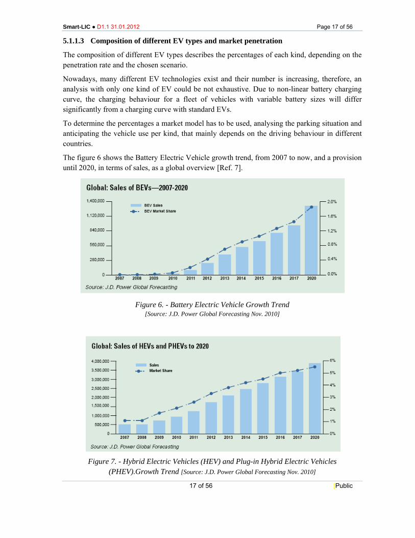
The figure 6 shows the Battery Electric Vehicle growth trend, from 2007 to now, and a provision until 2020, in terms of sales, as a global overview [Ref. 7].
Figure 6. - Battery Electric Vehicle Growth Trend
[Source: J.D. Power Global Forecasting Nov. 2010]
Figure 7. - Hybrid Electric Vehicles (HEV) and Plug-in Hybrid Electric Vehicles
(PHEV).Growth Trend [Source: J.D. Power Global Forecasting Nov. 2010]
Smart-LIC ● D1.1 31.01.2012 Page 18 of 56
18 of 56 [Public
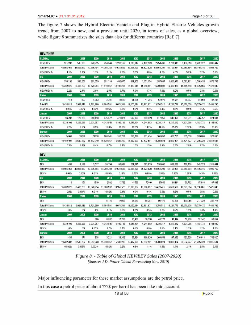
The figure 7 shows the Hybrid Electric Vehicle and Plug-in Hybrid Electric Vehicles growth trend, from 2007 to now, and a provision until 2020, in terms of sales, as a global overview, while figure 8 summarizes the sales data also for different countries [Ref. 7].
Figure 8. - Table of Global HEV/BEV Sales (2007-2020)
[Source: J.D. Power Global Forecasting Nov. 2010]
Major influencing parameter for these market assumptions are the petrol price.
In this case a petrol price of about ???$ per barril has been take into account.
Smart-LIC ● D1.1 31.01.2012 Page 19 of 56
19 of 56 [Public
Concerning the expectations of customers and chances of market penetration, a certain amount of uncertainty is related to the EV, mainly due to the following concerns:
• Driving range;
• Lifetime of the battery;
• Cost of the battery;
• Charging time;
• Reliability/fault tolerance (methods to determine if a battery is damaged);
• Possible fraud on battery age / number of cycles;
• Safety aspects;
• Availability of charging stations.
5.1.1.4 Battery technologies for EV
PHEV and BEV have batteries as energy storage of electrical drives, so they are a crucial component in future vehicles. In electric mobility development of BEV´s, research focuses on batteries with high energy densities and, as a consequence, costs, security, charging-time and life-time are very important.
Nowadays the energy density of designed battery systems reaches 1-2% of fluid fuels [Ref. 3]: it’s quite low so the size weight and cost/kW/h of the battery is the limiting factor for the driving range. EVs need a very high specific energy, while higher specific power is required for Fast Charge.
Possible types of batteries applied to electric vehicles are:
• several types of Lithium-ion;
• NaNiCl2;
• NiMH;
• NiCd
• Lead acid;
• Super capacitors;
• Redox flow.
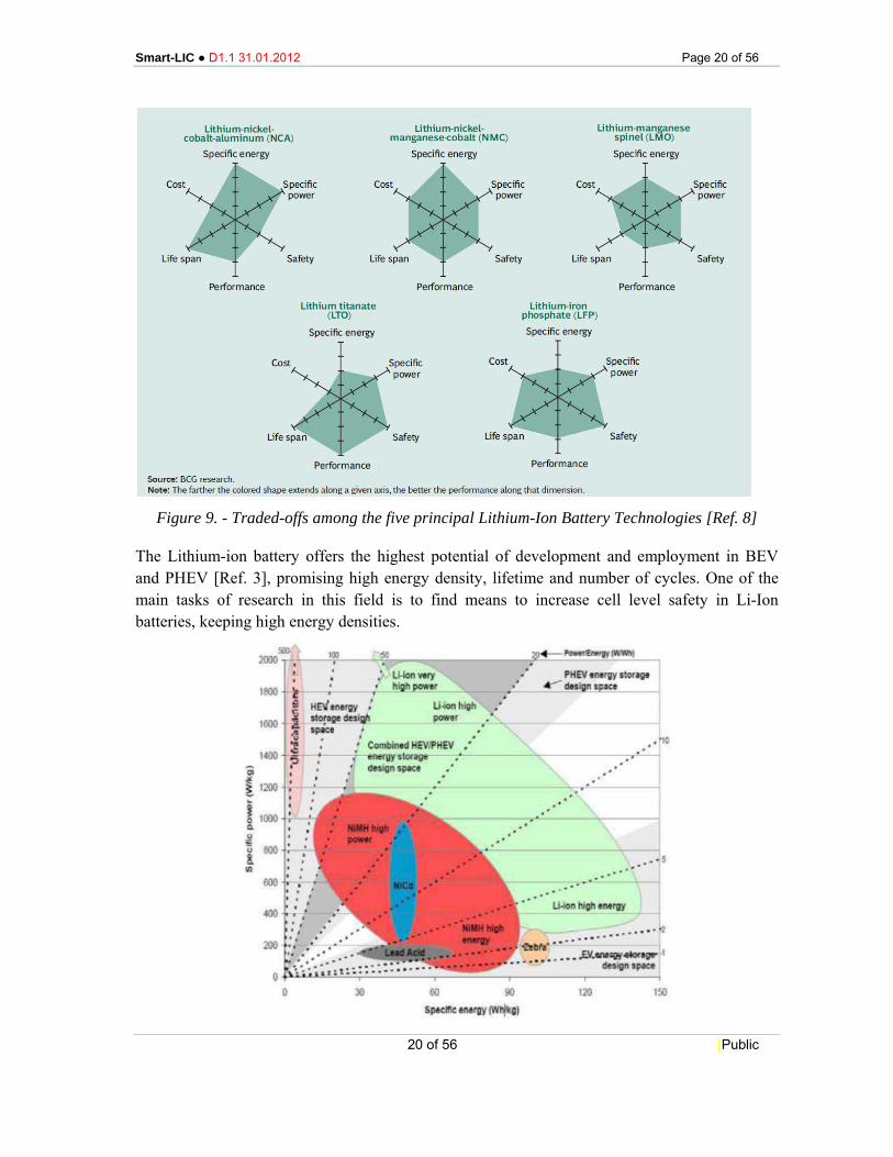
Figure 9 shows the traded-offs among the five principal Lithium-Ion Battery Technologies: the farther the coloured shape extends along a given axis, the better the performance along the dimension. As the graphs shows, no single technology wins along all the six dimensions: choosing a technology that optimizes performances along one dimension, inevitably means compromising on other dimensions [Ref. 8].
Smart-LIC ● D1.1 31.01.2012 Page 20 of 56
20 of 56 [Public
Figure 9. - Traded-offs among the five principal Lithium-Ion Battery Technologies [Ref. 8]
The Lithium-ion battery offers the highest potential of development and employment in BEV and PHEV [Ref. 3], promising high energy density, lifetime and number of cycles. One of the main tasks of research in this field is to find means to increase cell level safety in Li-Ion batteries, keeping high energy densities.
Smart-LIC ● D1.1 31.01.2012 Page 21 of 56
21 of 56 [Public
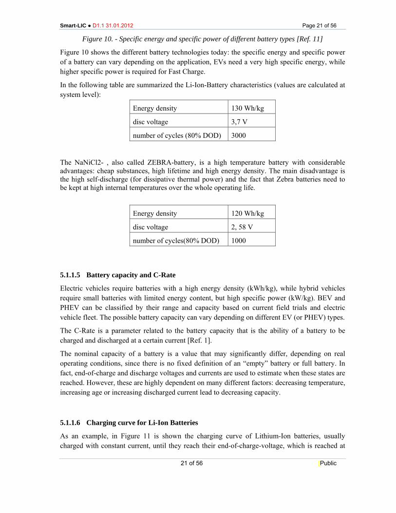
Figure 10. - Specific energy and specific power of different battery types [Ref. 11]
Figure 10 shows the different battery technologies today: the specific energy and specific power of a battery can vary depending on the application, EVs need a very high specific energy, while higher specific power is required for Fast Charge.
In the following table are summarized the Li-Ion-Battery characteristics (values are calculated at system level):
Energy density 130 Wh/kg
disc voltage 3,7 V
number of cycles (80% DOD) 3000
The NaNiCl2- , also called ZEBRA-battery, is a high temperature battery with considerable advantages: cheap substances, high lifetime and high energy density. The main disadvantage is the high self-discharge (for dissipative thermal power) and the fact that Zebra batteries need to be kept at high internal temperatures over the whole operating life.
Energy density 120 Wh/kg
disc voltage 2, 58 V
number of cycles(80% DOD) 1000
5.1.1.5 Battery capacity and C-Rate
Electric vehicles require batteries with a high energy density (kWh/kg), while hybrid vehicles require small batteries with limited energy content, but high specific power (kW/kg). BEV and PHEV can be classified by their range and capacity based on current field trials and electric vehicle fleet. The possible battery capacity can vary depending on different EV (or PHEV) types.
The C-Rate is a parameter related to the battery capacity that is the ability of a battery to be charged and discharged at a certain current [Ref. 1].
The nominal capacity of a battery is a value that may significantly differ, depending on real operating conditions, since there is no fixed definition of an “empty” battery or full battery. In fact, end-of-charge and discharge voltages and currents are used to estimate when these states are reached. However, these are highly dependent on many different factors: decreasing temperature, increasing age or increasing discharged current lead to decreasing capacity.
5.1.1.6 Charging curve for Li-Ion Batteries
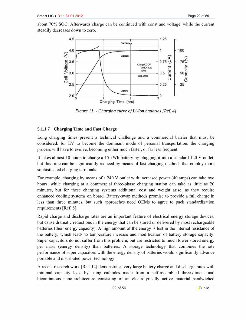
As an example, in Figure 11 is shown the charging curve of Lithium-Ion batteries, usually charged with constant current, until they reach their end-of-charge-voltage, which is reached at
Smart-LIC ● D1.1 31.01.2012 Page 22 of 56
22 of 56 [Public
about 70% SOC. Afterwards charge can be continued with const and voltage, while the current steadily decreases down to zero.
Figure 11. - Charging curve of Li-Ion batteries [Ref. 4]
5.1.1.7 Charging Time and Fast Charge
Long charging times present a technical challenge and a commercial barrier that must be considered: for EV to become the dominant mode of personal transportation, the charging process will have to evolve, becoming either much faster, or far less frequent.
It takes almost 10 hours to charge a 15 kWh battery by plugging it into a standard 120 V outlet, but this time can be significantly reduced by means of fast charging methods that employ more sophisticated charging terminals.
For example, charging by means of a 240 V outlet with increased power (40 amps) can take two hours, while charging at a commercial three-phase charging station can take as little as 20 minutes, but for these charging systems additional cost and weight arise, as they require enhanced cooling systems on board. Battery-swap methods promise to provide a full charge in less than three minutes, but such approaches need OEMs to agree to pack standardization requirements [Ref. 8].
Rapid charge and discharge rates are an important feature of electrical energy storage devices, but cause dramatic reductions in the energy that can be stored or delivered by most rechargeable batteries (their energy capacity). A high amount of the energy is lost in the internal resistance of the battery, which leads to temperature increase and modification of battery storage capacity. Super capacitors do not suffer from this problem, but are restricted to much lower stored energy per mass (energy density) than batteries. A storage technology that combines the rate performance of super capacitors with the energy density of batteries would significantly advance portable and distributed power technology.
A recent research work [Ref. 12] demonstrates very large battery charge and discharge rates with minimal capacity loss, by using cathodes made from a self-assembled three-dimensional bicontinuous nano-architecture consisting of an electrolytically active material sandwiched
Smart-LIC ● D1.1 31.01.2012 Page 23 of 56
23 of 56 [Public
between rapid ion and electron transport pathways. Rates of up to 400C and 1,000C for lithium-ion and nickel-metal hydride chemistries, respectively, are achieved (where a 1C rate represents a one-hour complete charge or discharge), enabling fabrication of a lithium-ion battery that can be 90% charged in 2 minutes.
Prototypes for both nickel metal hydride (NiMH) and lithium-ion batteries, using cathodes of nickel oxyhydroxide (NiOOH) and lithiated manganese dioxide (MnO2), respectively have been created. An electrolyte then fills the remaining holes. This design provides large areas of contact between the nickel, cathode, and electrode without sacrificing much cathode volume.
The biggest drawback is the increased amperage: the major obstacle to uptake of these batteries is the larger current necessary to charge the batteries so quickly. EV, in particular, would need to be adapted to properly handle the swift movement of so many electrons.
NiCd batteries have long been considered, but show the memory effect and problems in recyclability.
Furthermore, the batteries based on new chemistry probably will be available for production on a significant scale by 2020.
5.1.1.8 Battery lifetime
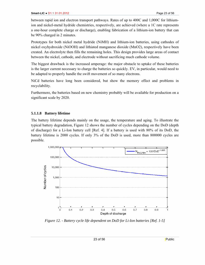
The battery lifetime depends mainly on the usage, the temperature and aging. To illustrate the typical battery degradation, Figure 12 shows the number of cycles depending on the DoD (depth of discharge) for a Li-Ion battery cell [Ref. 4]. If a battery is used with 80% of its DoD, the battery lifetime is 2000 cycles. If only 3% of the DoD is used, more than 800000 cycles are possible.
Figure 12. - Battery cycle life dependent on DoD for Li-Ion batteries [Ref. 1-5]
Smart-LIC ● D1.1 31.01.2012 Page 24 of 56
24 of 56 [Public
The following equation is used to estimate the number of cycles Nlife to determine the battery lifetime depending on the DoD:
Nlife = a * DoDb.
For a Li-Ion battery the parameter values are:
a = 1331 and b = -1,825.
This equation is used to calculate the cycle life of Li-Ion batteries, but some very important parameters are not taken into account in this equation, such as:
• Temperature; • C-Rate; • Different Li-Ion battery chemistries; • Battery dimensions; • Battery ageing due to calendar life; • Long time periods with discharged battery status.
5.1.1.9 Battery investment costs and costs of battery life cycle and degradation
These are two aspects to be evaluated from an economic and an environmental point of view, and the second parameter strongly depends on the first one.
As a rough estimate of the SMART-LIC Project the BMS cost target is considered to be within 10% of cell cost.
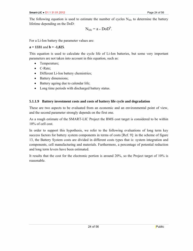
In order to support this hypothesis, we refer to the following evaluations of long term key success factors for battery system components in terms of costs [Ref. 9]: in the scheme of figure 13, the Battery System costs are divided in different costs types that is: system integration and components, cell manufacturing and materials. Furthermore, a percentage of potential reduction and long term levers have been estimated.
It results that the cost for the electronic portion is around 20%, so the Project target of 10% is reasonable.
Smart-LIC ● D1.1 31.01.2012 Page 25 of 56
25 of 56 [Public
Figure 13. - Long Term Key Success Factors [Ref. 9]
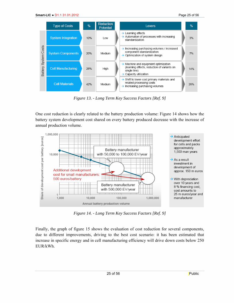
One cost reduction is clearly related to the battery production volume: Figure 14 shows how the battery system development cost shared on every battery produced decrease with the increase of annual production volume.
Figure 14. - Long Term Key Success Factors [Ref. 9]
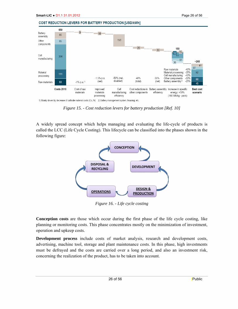
Finally, the graph of figure 15 shows the evaluation of cost reduction for several components, due to different improvements, driving to the best cost scenario: it has been estimated that increase in specific energy and in cell manufacturing efficiency will drive down costs below 250 EUR/kWh.
Smart-LI
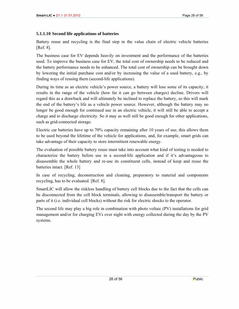
A widecalled thfollowin
Concepplanningoperatio
Developadvertismust beconcern
C ● D1.1 31.0
Fig
ely spread che LCC (Ling figure:
ption costs g or monitoon and upke
pment prosing, machine defrayed ning the real
01.2012
gure 15. - Co
concept whfe Cycle Co
are those woring costs. eep costs.
ocess includne tool, stoand the co
lization of th
ost reductio
hich helps mosting). Thi
Figure
which occuThis phase
de costs oorage and plosts are carhe product,
26 of 56
on levers for
managing as lifecycle c
16. - Life cy
ur during thconcentrate
of market alant mainterried over a
has to be ta
r battery pr
and evaluatcan be class
ycle costing
he first phaes mostly on
analysis, renance costsa long perioaken into ac
oduction [R
ting the lifesified into th
g
ase of the ln the minim
esearch ands. In this phod, and alsccount.
Pag
Ref. 10]
e-cycle of he phases sh
ife cycle comization of i
d developmhase, high iso an inves
e 26 of 56
[Public
products ishown in the
osting, likeinvestment,
ment costs,investmentsstment risk,
s e
e ,
, s ,

Smart-LIC ● D1.1 31.01.2012 Page 27 of 56
27 of 56 [Public
Design and production costs are the costs of materials and manufactures, the labour costs, to be differed between fixed and proportional costs. All in all are the production costs very important when it comes to production decisions and price decisions.
Operations costs occur during the use of a product or a technology, when there is no influence on costs reduction. This phase is also helpful in order to optimize the operating procedure.
Disposal and recycling costs arise after the product or the technology is used.
Also the battery degradation costs have to be estimated: where there is no experience with the new battery types and new BMS, models have to be used. However, the battery degradation process is too complex to use a physical battery model so a simplified cost model based on the DoD can be suitable to estimate the costs of battery degradation [Ref. 5].
Smart-LIC ● D1.1 31.01.2012 Page 28 of 56
28 of 56 [Public
5.1.1.10 Second life applications of batteries
Battery reuse and recycling is the final step in the value chain of electric vehicle batteries [Ref. 8].
The business case for EV depends heavily on investment and the performance of the batteries used. To improve the business case for EV, the total cost of ownership needs to be reduced and the battery performance needs to be enhanced. The total cost of ownership can be brought down by lowering the initial purchase cost and/or by increasing the value of a used battery, e.g., by finding ways of reusing them (second-life applications).
During its time as an electric vehicle’s power source, a battery will lose some of its capacity; it results in the range of the vehicle (how far it can go between charges) decline. Drivers will regard this as a drawback and will ultimately be inclined to replace the battery, so this will mark the end of the battery’s life as a vehicle power source. However, although the battery may no longer be good enough for continued use in an electric vehicle, it will still be able to accept a charge and to discharge electricity. So it may as well still be good enough for other applications, such as grid-connected storage.
Electric car batteries have up to 70% capacity remaining after 10 years of use, this allows them to be used beyond the lifetime of the vehicle for applications, and, for example, smart grids can take advantage of their capacity to store intermittent renewable energy.
The evaluation of possible battery reuse must take into account what kind of testing is needed to characterize the battery before use in a second-life application and if it’s advantageous to disassemble the whole battery and re-use its constituent cells, instead of keep and reuse the batteries intact. [Ref. 13]
In case of recycling, deconstruction and cleaning, preparatory to material and components recycling, has to be evaluated. [Ref. 8].
SmartLIC will allow the riskless handling of battery cell blocks due to the fact that the cells can be disconnected from the cell block terminals, allowing to disassemble/transport the battery or parts of it (i.e. individual cell blocks) without the risk for electric shocks to the operator.
The second life may play a big role in combination with photo voltaic (PV) installations for grid management and/or for charging EVs over night with energy collected during the day by the PV systems.
Smart-LI
5.1.
5.1.2.1 TypicalPassive Relays needed
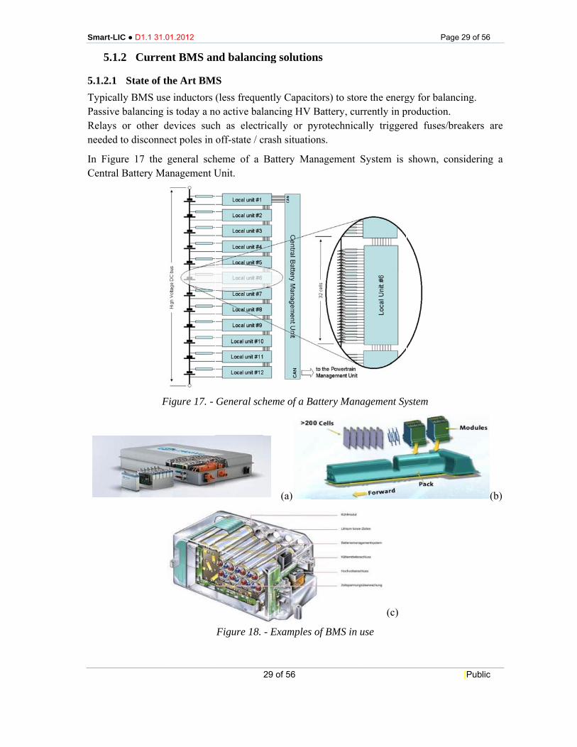
In FiguCentral
C ● D1.1 31.0
.2 Curren
State of thly BMS usebalancing ior other dto disconne
ure 17 the gBattery Ma
F
01.2012
nt BMS an
he Art BMe inductors is today a nodevices suchect poles in
general schanagement U
Figure 17. -
nd balanci
MS (less frequeo active balh as electroff-state / c
heme of a Unit.
General sch
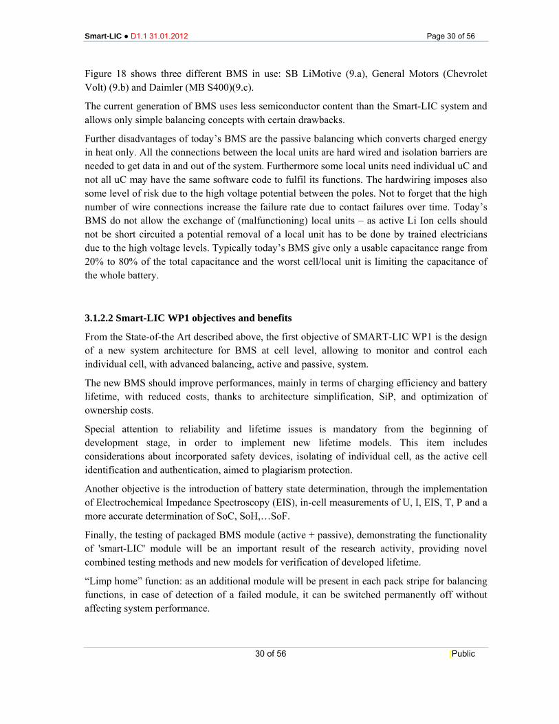
Figure 18.
29 of 56
ing solutio
ently Capacilancing HV rically or pcrash situatio
Battery Ma
heme of a B
(a)
- Examples
ons
itors) to stoBattery, cu
pyrotechnicaons.
anagement
Battery Man
s of BMS in
ore the energurrently in pally trigger
System is
nagement Sy
(c (c)
use
Pag
gy for balanproduction. red fuses/br
shown, con
ystem
e 29 of 56
[Public
ncing.
reakers are
nsidering a
(b)
e
a
Smart-LIC ● D1.1 31.01.2012 Page 30 of 56
30 of 56 [Public
Figure 18 shows three different BMS in use: SB LiMotive (9.a), General Motors (Chevrolet Volt) (9.b) and Daimler (MB S400)(9.c).
The current generation of BMS uses less semiconductor content than the Smart-LIC system and allows only simple balancing concepts with certain drawbacks.
Further disadvantages of today’s BMS are the passive balancing which converts charged energy in heat only. All the connections between the local units are hard wired and isolation barriers are needed to get data in and out of the system. Furthermore some local units need individual uC and not all uC may have the same software code to fulfil its functions. The hardwiring imposes also some level of risk due to the high voltage potential between the poles. Not to forget that the high number of wire connections increase the failure rate due to contact failures over time. Today’s BMS do not allow the exchange of (malfunctioning) local units – as active Li Ion cells should not be short circuited a potential removal of a local unit has to be done by trained electricians due to the high voltage levels. Typically today’s BMS give only a usable capacitance range from 20% to 80% of the total capacitance and the worst cell/local unit is limiting the capacitance of the whole battery.
3.1.2.2 Smart-LIC WP1 objectives and benefits
From the State-of-the Art described above, the first objective of SMART-LIC WP1 is the design of a new system architecture for BMS at cell level, allowing to monitor and control each individual cell, with advanced balancing, active and passive, system.
The new BMS should improve performances, mainly in terms of charging efficiency and battery lifetime, with reduced costs, thanks to architecture simplification, SiP, and optimization of ownership costs.
Special attention to reliability and lifetime issues is mandatory from the beginning of development stage, in order to implement new lifetime models. This item includes considerations about incorporated safety devices, isolating of individual cell, as the active cell identification and authentication, aimed to plagiarism protection.
Another objective is the introduction of battery state determination, through the implementation of Electrochemical Impedance Spectroscopy (EIS), in-cell measurements of U, I, EIS, T, P and a more accurate determination of SoC, SoH,…SoF.
Finally, the testing of packaged BMS module (active + passive), demonstrating the functionality of 'smart-LIC' module will be an important result of the research activity, providing novel combined testing methods and new models for verification of developed lifetime.
“Limp home” function: as an additional module will be present in each pack stripe for balancing functions, in case of detection of a failed module, it can be switched permanently off without affecting system performance.
Smart-LI
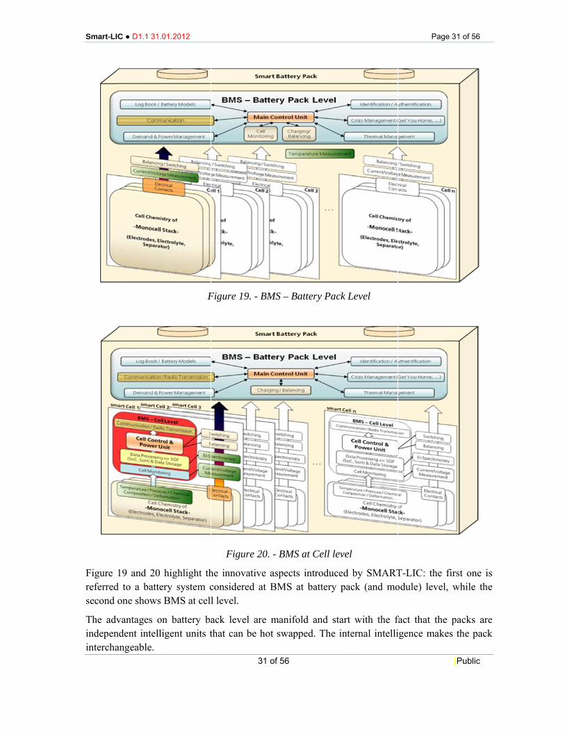
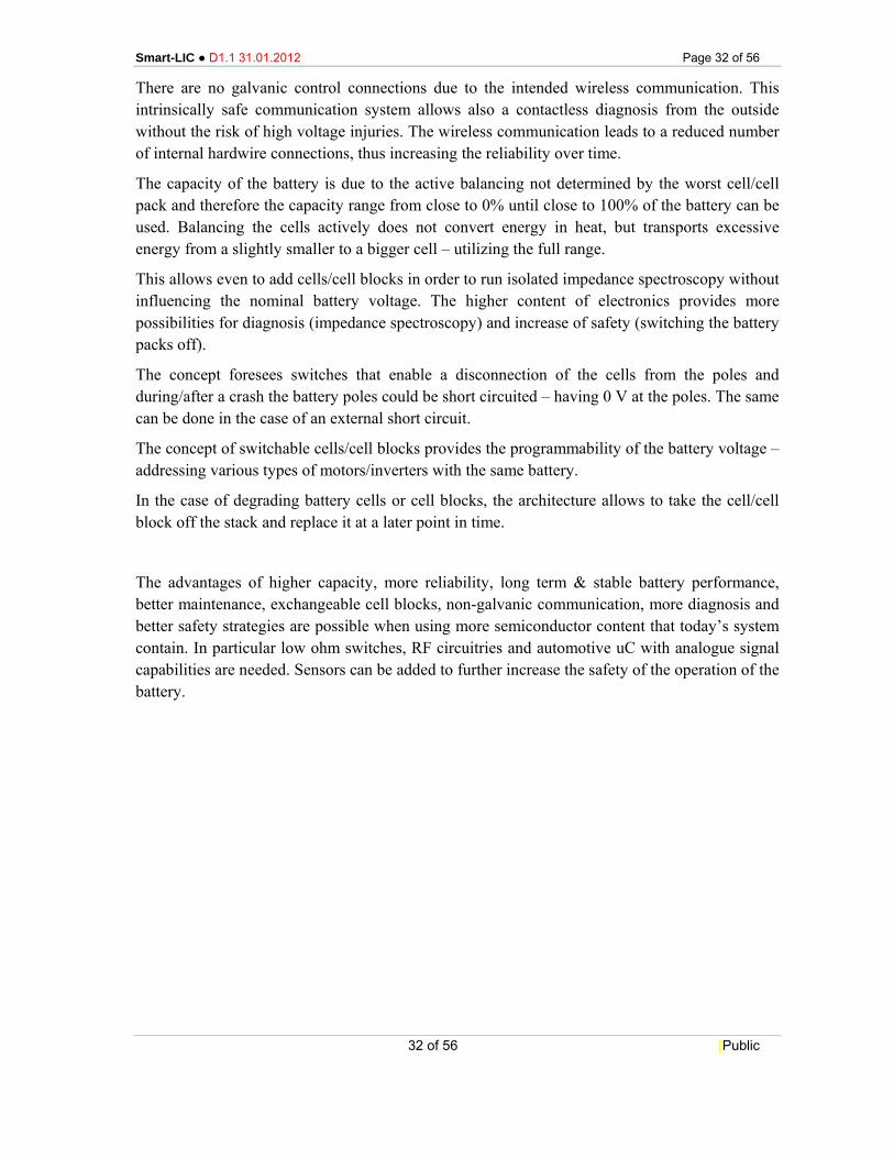
Figure referredsecond
The advindepenintercha
C ● D1.1 31.0
19 and 20 hd to a batterone shows B
vantages onndent intelliangeable.
01.2012
F
highlight thry system cBMS at cell
n battery bagent units t
Figure 19. -
Figure 2
he innovativconsidered l level.
ack level athat can be
31 of 56
BMS – Bat
20. - BMS a
ve aspects iat BMS at
are manifoldhot swappe
ttery Pack L
at Cell level
introduced battery pac
d and start ed. The inte
Level
l
by SMARTck (and mo
with the fernal intelli
Pag
T-LIC: the odule) level
fact that theigence make
e 31 of 56
[Public
first one isl, while the
e packs arees the pack
s e
e k
Smart-LIC ● D1.1 31.01.2012 Page 32 of 56
32 of 56 [Public
There are no galvanic control connections due to the intended wireless communication. This intrinsically safe communication system allows also a contactless diagnosis from the outside without the risk of high voltage injuries. The wireless communication leads to a reduced number of internal hardwire connections, thus increasing the reliability over time.
The capacity of the battery is due to the active balancing not determined by the worst cell/cell pack and therefore the capacity range from close to 0% until close to 100% of the battery can be used. Balancing the cells actively does not convert energy in heat, but transports excessive energy from a slightly smaller to a bigger cell – utilizing the full range.
This allows even to add cells/cell blocks in order to run isolated impedance spectroscopy without influencing the nominal battery voltage. The higher content of electronics provides more possibilities for diagnosis (impedance spectroscopy) and increase of safety (switching the battery packs off).
The concept foresees switches that enable a disconnection of the cells from the poles and during/after a crash the battery poles could be short circuited – having 0 V at the poles. The same can be done in the case of an external short circuit.
The concept of switchable cells/cell blocks provides the programmability of the battery voltage – addressing various types of motors/inverters with the same battery.
In the case of degrading battery cells or cell blocks, the architecture allows to take the cell/cell block off the stack and replace it at a later point in time.
The advantages of higher capacity, more reliability, long term & stable battery performance, better maintenance, exchangeable cell blocks, non-galvanic communication, more diagnosis and better safety strategies are possible when using more semiconductor content that today’s system contain. In particular low ohm switches, RF circuitries and automotive uC with analogue signal capabilities are needed. Sensors can be added to further increase the safety of the operation of the battery.
Smart-LI
5.1.Packagisecure ainvestigcell.
Current module housinginfluenc
The chipotting
Figure position
ElectronelectronLTCC, The eleindividuvibratioliquids isealed w
These aTherefoare oper
Figure
C ● D1.1 31.0
.3 Reviewing/system and cost effgations for s
t BMS are level by w
g. The metaces.
ip-level devwith differe
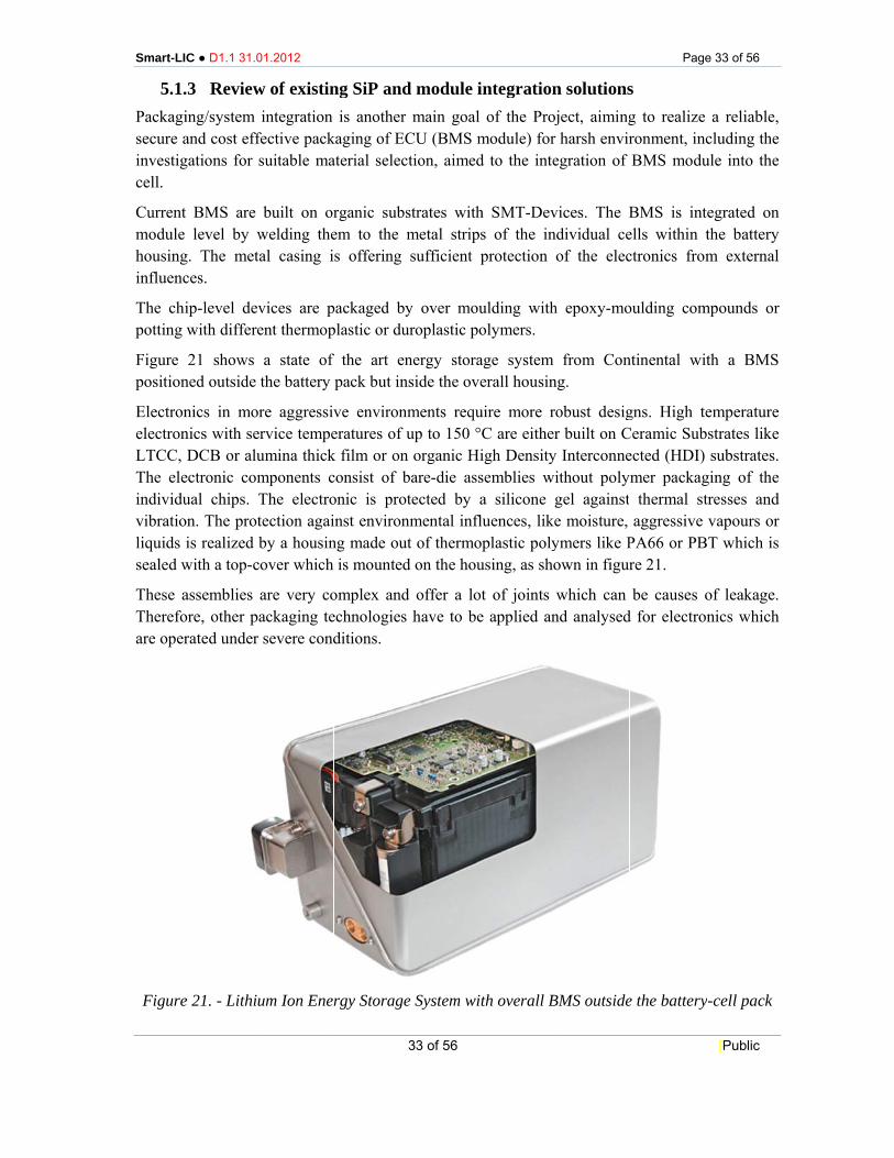
21 shows ned outside
nics in mornics with serDCB or alu
ectronic comual chips. Ton. The protis realized b
with a top-c
assemblies ore, other parated under
e 21. - Lithiu
01.2012
w of existinintegration
fective packsuitable ma
built on orwelding theal casing i
vices are pent thermop
a state of the battery
re aggressivrvice tempeumina thickmponents cThe electrotection agaiby a housinover which
are very coackaging tesevere cond
um Ion Ener
ng SiP andis another
kaging of ECaterial selec
rganic subsem to the ms offering
packaged byplastic or du
f the art enpack but in
ve environmeratures of uk film or onconsist of bonic is protinst environng made out
is mounted
omplex andechnologies ditions.
rgy Storage
33 of 56
d module imain goal
CU (BMS mtion, aimed
strates withmetal stripssufficient p
y over mouuroplastic po
nergy storaside the ove
ments requup to 150 °
n organic Hibare-die asstected by a
nmental inflt of thermo
d on the hou
d offer a lothave to be
e System wit
integrationof the Proj
module) for d to the inte
h SMT-Devs of the inprotection
ulding witholymers.
age system erall housin
uire more roC are eitherigh Densitysemblies wia silicone gluences, likeplastic poly
using, as sho
t of joints e applied an
th overall B
n solutionsject, aimingharsh envir
egration of
vices. The Bndividual ceof the elec
h epoxy-mo
from Conng.
obust desigr built on C
y Interconneithout polygel against e moisture, ymers like Pown in figur
which can nd analysed
BMS outside
Pag
s g to realizeronment, inBMS modu
BMS is intells within ctronics fro
oulding com
ntinental wi
gns. High tCeramic Subected (HDI)mer packagthermal st
aggressive PA66 or PBre 21.
be causes d for electro
e the battery
e 33 of 56
[Public
e a reliable,ncluding theule into the
tegrated onthe battery
om external
mpounds or
ith a BMS
temperaturebstrates like) substrates.ging of thetresses andvapours or
BT which is
of leakage.onics which
y-cell pack
, e e
n y l
r
S
e e . e d r s
. h
Smart-LIC ● D1.1 31.01.2012 Page 34 of 56
34 of 56 [Public
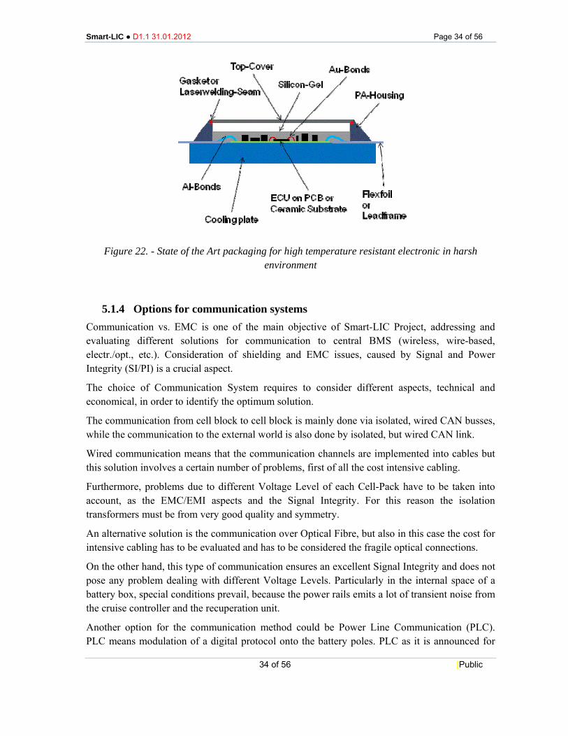
Figure 22. - State of the Art packaging for high temperature resistant electronic in harsh
environment
5.1.4 Options for communication systems Communication vs. EMC is one of the main objective of Smart-LIC Project, addressing and evaluating different solutions for communication to central BMS (wireless, wire-based, electr./opt., etc.). Consideration of shielding and EMC issues, caused by Signal and Power Integrity (SI/PI) is a crucial aspect.
The choice of Communication System requires to consider different aspects, technical and economical, in order to identify the optimum solution.
The communication from cell block to cell block is mainly done via isolated, wired CAN busses, while the communication to the external world is also done by isolated, but wired CAN link.
Wired communication means that the communication channels are implemented into cables but this solution involves a certain number of problems, first of all the cost intensive cabling.
Furthermore, problems due to different Voltage Level of each Cell-Pack have to be taken into account, as the EMC/EMI aspects and the Signal Integrity. For this reason the isolation transformers must be from very good quality and symmetry.
An alternative solution is the communication over Optical Fibre, but also in this case the cost for intensive cabling has to be evaluated and has to be considered the fragile optical connections.
On the other hand, this type of communication ensures an excellent Signal Integrity and does not pose any problem dealing with different Voltage Levels. Particularly in the internal space of a battery box, special conditions prevail, because the power rails emits a lot of transient noise from the cruise controller and the recuperation unit.
Another option for the communication method could be Power Line Communication (PLC). PLC means modulation of a digital protocol onto the battery poles. PLC as it is announced for
Smart-LI
batteriescommunisolatedfor mOhgiven inimportaSTMicrblock sefeasibleThe wirpros andFinally,problemover OpPacks. Odesired voltage
The drainside th
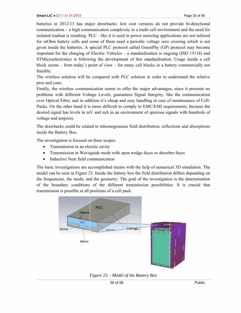
The inv• T• T• I
The basmodel cthe freqof the transmis
C ● D1.1 31.0
s in 2012/nication – a
d readout is hm battery nside the baant for the croelectroniceems – from
e. reless solutd cons. the wirele
ms with difptical Fibre,On the othesignal has and ampere
awbacks couhe Battery B
vestigation iTransmissioTransmissioInductive N
sic investigacan be seen quencies, th
boundary ssion is pos
01.2012
13 has maja high commresulting. Pcells and s
atteries. A scharging of s is follow
m today´s p
tion will be
ss communfferent Volt, and in adder hand it islevels in mVes.
uld be relateBox.
s focused onon in an eleon in Wave
Near field co
ations are acin Figure 2e mode, anconditions
ssible at all p
F
ajor drawbamunication PLC - like itsome of thespecial PLC
f Electric Vewing the devpoint of view
e compared
nication seetage Levelsdition it’s chs more diffiV and mA
ed to inhom
n three scopctric cavityguide mode
ommunicati
ccomplishe23. Inside thnd the geom
of the dpositions of
Figure 23. -35 of 56
acks: low ccomplexityt is used in em need a C protocol cehicles – a velopment w – for man
with PLC
ems to offers, guaranteeheap and eaicult to comin an enviro
mogeneous f
pes.
e with open ion
ed means wihe battery bo
metry. The gdifferent traf a cell pack
- Model of t
cost versiony in a multi
power meteperiodic vocalled Greestandardisaof this stanny cell bloc
solution in
r the majores Signal Inasy handlin
mply to EMConment of s
field distrib
wedge-face
ith the helpox the field
goal of the iansmission k.
the Battery
ns do not cell environering applicoltage zero enPhy (GP) ation is ongndardisationcks in a bat
n order to u
r advantagentegrity, likg in case ofC/EMI requspurious sig
bution, refle
es or absorb
of numericd distributioninvestigatiopossibilitie
Box
Pag
provide binment and tcations are ncrossing wprotocol m
going (ISO n. Usage inttery comme
understand t
s, since it pke the comf maintenanuirements, bgnals with h
ctions and a
ber-faces
cal 3D simun differs de
on is the detes. It is c
e 35 of 56
[Public
-directionalthe need fornot tailored
which is notmay become
15118) andnside a cellercially not
the relative
presents nommunicationnce of Cell-because thehundreds of
absorptions
ulation. Theepending ontermination
crucial that
l r d t e d l t
e
o n -e f
s
e n n t
Smart-LI
C ● D1.1 31.001.2012
F
Figure 25
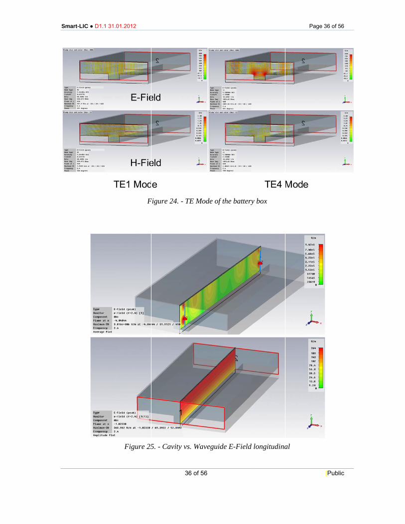
Figure 24. -
5. - Cavity v
36 of 56
TE Mode of
vs. Wavegui
f the battery
ide E-Field
y box
longitudina
Pag
al
e 36 of 56
[Public
Smart-LIC ● D1.1 31.01.2012 Page 37 of 56
37 of 56 [Public
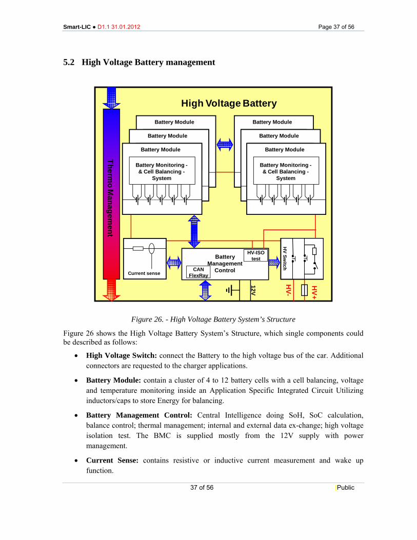
5.2 High Voltage Battery management
Figure 26. - High Voltage Battery System’s Structure
Figure 26 shows the High Voltage Battery System’s Structure, which single components could be described as follows:
• High Voltage Switch: connect the Battery to the high voltage bus of the car. Additional connectors are requested to the charger applications.
• Battery Module: contain a cluster of 4 to 12 battery cells with a cell balancing, voltage and temperature monitoring inside an Application Specific Integrated Circuit Utilizing inductors/caps to store Energy for balancing.
• Battery Management Control: Central Intelligence doing SoH, SoC calculation, balance control; thermal management; internal and external data ex-change; high voltage isolation test. The BMC is supplied mostly from the 12V supply with power management.
• Current Sense: contains resistive or inductive current measurement and wake up function.
HV Sw
itchH
V Switch
12V
HV+
High Voltage Battery
Thermo M
anagement
Battery Management
ControlCANFlexRay
HV-ISOtest
HV-
Battery Monitoring -& Cell Balancing -
System
Battery Module
Battery Monitoring -& Cell Balancing -
System
Battery Module
Battery Monitoring -& Cell Balancing -
System
Battery Module
Battery Monitoring -& Cell Balancing -
System
Battery Module
Battery Monitoring -& Cell Balancing -
System
Battery Module
Battery Monitoring -& Cell Balancing -
System
Battery Module
Current sense

Smart-LIC ● D1.1 31.01.2012 Page 38 of 56
38 of 56 [Public
Figure 27. - System’s General Structure
Generally speaking, the possibility of intervention or modification on a defined structure depends mainly on the impact on energy/power and on voltage.
Pre-charge function which is present on the High Voltage Switch unit can be removed due to the presence of switches in each module.
Smart-LIC ● D1.1 31.01.2012 Page 39 of 56
39 of 56 [Public
6 SYSTEM REQUIREMENTS CAPTURE
6.1 Application context The first point to be investigated is the target application for the SMART-LIC battery system to be developed in the Project; mainly in terms of:
• The vehicle types in which the battery system should be later integrated (at least theoretically);
• Minimum range;
• Typical energy consumption of the envisaged test vehicle type.
Some specific problems are investigated by means of the questionnaire, mainly concerning the smart battery system architecture, for instance the possibility to bypass one cell block in a string of cell blocks and, in general, about the structure and distribution of string cell blocks.
The questionnaire analyses also the requirements regarding the energy storage capacity, the maximum output power/current and battery voltage.
In terms of battery pack organization, several solutions are available, for instance: serial connected cells, serial connected modules, parallel connected strings or battery pack system.
Indications about the standard requirements to be complied are also needed, concerning the several aspects of the Project goal, that are, generally speaking, the standards used in Automotive applications, in particular:
• EMI standards for Electromagnetic interference;
• ESD standards, for Electrostatic discharge;
• EMC standards, for electromagnetic compatibility.
6.2 Questionnaire In order to collect information about system requirements a questionnaire has been provided to partners, investigating the main aspects of the object.
The questionnaire is divided in two parts; the first one collects information/suggestions about the following Main Requirements:
1. Environmental Conditions;
2. Electrical Requirements;
3. Mechanical requirements;
4. Communication requirements.

Smart-LIC ● D1.1 31.01.2012 Page 40 of 56
40 of 56 [Public
In each area, some secondary requirements have been identified, such as:
• Operative and storage temperature;
• Vibrations to that the system could be subjected;
• Energy efficiency;
• Power and voltage levels;
• Discharge and recharge processes;
• Lifecycle;
• Modularity;
• Volume and weight;
• BMS power supply;
• Data communication protocol and speed.
The second part of the questionnaire concerns the target application in terms of vehicle type, the preferable Battery Pack structure and collects indications about standards to fulfil, especially by the safety point of view.
The cost target is also addressed in the questionnaire, but more general considerations are reported in the following.
Smart-LIC ● D1.1 31.01.2012 Page 41 of 56
41 of 56 [Public
6.3 Requirements definition: questionnaire analysis
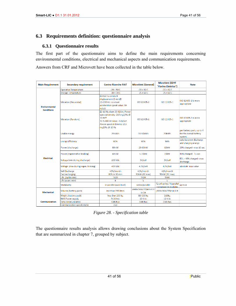
6.3.1 Questionnaire results The first part of the questionnaire aims to define the main requirements concerning environmental conditions, electrical and mechanical aspects and communication requirements.
Answers from CRF and Microvett have been collected in the table below.
Figure 28. - Specification table
The questionnaire results analysis allows drawing conclusions about the System Specification that are summarized in chapter 7, grouped by subject.
Smart-LIC ● D1.1 31.01.2012 Page 42 of 56
42 of 56 [Public
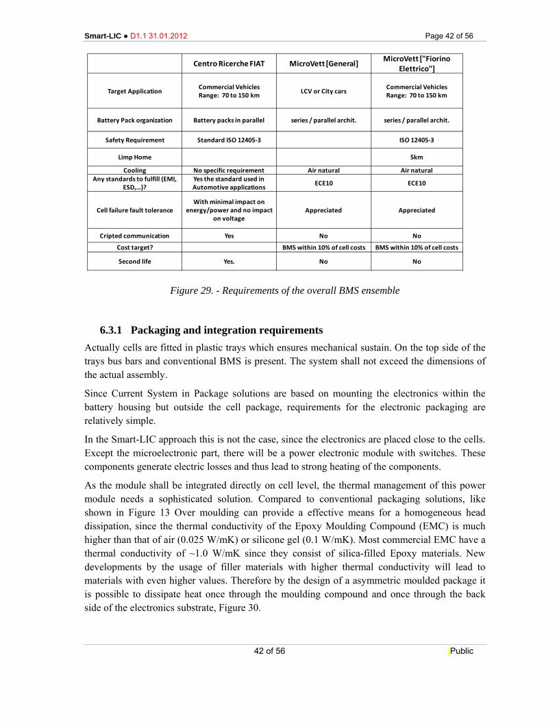
Figure 29. - Requirements of the overall BMS ensemble
6.3.1 Packaging and integration requirements Actually cells are fitted in plastic trays which ensures mechanical sustain. On the top side of the trays bus bars and conventional BMS is present. The system shall not exceed the dimensions of the actual assembly.
Since Current System in Package solutions are based on mounting the electronics within the battery housing but outside the cell package, requirements for the electronic packaging are relatively simple.
In the Smart-LIC approach this is not the case, since the electronics are placed close to the cells. Except the microelectronic part, there will be a power electronic module with switches. These components generate electric losses and thus lead to strong heating of the components.
As the module shall be integrated directly on cell level, the thermal management of this power module needs a sophisticated solution. Compared to conventional packaging solutions, like shown in Figure 13 Over moulding can provide a effective means for a homogeneous head dissipation, since the thermal conductivity of the Epoxy Moulding Compound (EMC) is much higher than that of air (0.025 W/mK) or silicone gel (0.1 W/mK). Most commercial EMC have a thermal conductivity of ~1.0 W/mK since they consist of silica-filled Epoxy materials. New developments by the usage of filler materials with higher thermal conductivity will lead to materials with even higher values. Therefore by the design of a asymmetric moulded package it is possible to dissipate heat once through the moulding compound and once through the back side of the electronics substrate, Figure 30.
Centro Ricerche FIAT MicroVett [General] MicroVett ["Fiorino Elettrico"]
Target Application Commercial Vehicles Range: 70 to 150 km LCV or City cars Commercial Vehicles
Range: 70 to 150 km
Battery Pack organization Battery packs in parallel series / parallel archit. series / parallel archit.
Safety Requirement Standard ISO 12405‐3 ISO 12405‐3
Limp Home 5km
Cooling No specific requirement Air natural Air naturalAny standards to fulfill (EMI,
ESD,…)?Yes the standard used in Automotive applications ECE10 ECE10
Cell failure fault toleranceWith minimal impact on
energy/power and no impact on voltage
Appreciated Appreciated
Cripted communication Yes No No
Cost target? BMS within 10% of cell costs BMS within 10% of cell costs
Second life Yes. No No
Smart-LIC ● D1.1 31.01.2012 Page 43 of 56
43 of 56 [Public
Figure 30. - Design and Heat-dissipation through a asymmetric, moulded electronic package
EMC offer the advantage of being thermally and chemically very stable. Therefore they can withstand temperatures above 200 °C which can emerge in electronic power modules. Further on they are resistant against fluids and vapours like oil, moisture and acidic substances which can occur inside or close to the battery cells.
Possible Material Suppliers are companies like Hitachi Chemical, Nitto Denko, Kyocera Chemical, Shin-Etsu Chemical, Henkel, Sumitomo Bakelite or Duresco.
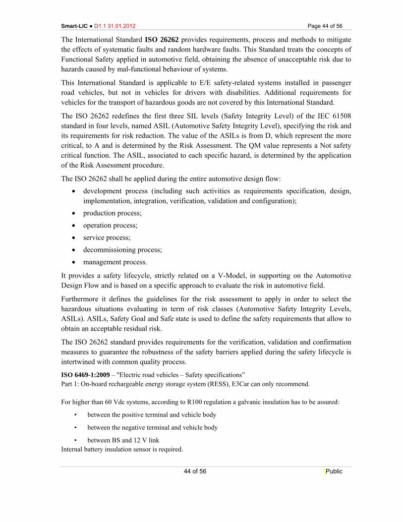
The Material Requirements for EMC are listed in Figure 31.
Property TC CTE E Tg Mould
Shrinkage Unit W/mK ppm/K GPa °C % typical 0.8 ‐ 5 9‐25 15‐30 120‐240 ‐0.04 ‐ 0.2 aspired 3 9‐16 15‐20 150‐200 < 0.05
Figure 31. - Typical and aspired Material Parameters for Epoxy Moulding Compounds
6.3.2 Safety requirements - ASIL according to ISO26262 Concerning safety, the main reference standard is the standard ISO 12405-3, “Electrically propelled road vehicles - Test specification for Lithium-ion traction battery packs and systems -- Part 3: Safety performance requirements.
According to ISO/WD 12405-3 (Li-ion based BS) Safety performance requirements, for higher than 60 Vdc systems, complying to R100 regulation, a galvanic insulation has to be assured: • between the positive terminal and vehicle body; • between the negative terminal and vehicle body; • between BS and 12 V link.
Internal battery insulation sensor is required.
Bare Die with Au-Bonds Switch/Capacitor Al-Bond
Moulded Housing
Lead Frame
Cooling Plate
Cooling Plate
Smart-LIC ● D1.1 31.01.2012 Page 44 of 56
44 of 56 [Public
The International Standard ISO 26262 provides requirements, process and methods to mitigate the effects of systematic faults and random hardware faults. This Standard treats the concepts of Functional Safety applied in automotive field, obtaining the absence of unacceptable risk due to hazards caused by mal-functional behaviour of systems.
This International Standard is applicable to E/E safety-related systems installed in passenger road vehicles, but not in vehicles for drivers with disabilities. Additional requirements for vehicles for the transport of hazardous goods are not covered by this International Standard.
The ISO 26262 redefines the first three SIL levels (Safety Integrity Level) of the IEC 61508 standard in four levels, named ASIL (Automotive Safety Integrity Level), specifying the risk and its requirements for risk reduction. The value of the ASILs is from D, which represent the more critical, to A and is determined by the Risk Assessment. The QM value represents a Not safety critical function. The ASIL, associated to each specific hazard, is determined by the application of the Risk Assessment procedure.
The ISO 26262 shall be applied during the entire automotive design flow:
• development process (including such activities as requirements specification, design, implementation, integration, verification, validation and configuration);
• production process;
• operation process;
• service process;
• decommissioning process;
• management process.
It provides a safety lifecycle, strictly related on a V-Model, in supporting on the Automotive Design Flow and is based on a specific approach to evaluate the risk in automotive field.
Furthermore it defines the guidelines for the risk assessment to apply in order to select the hazardous situations evaluating in term of risk classes (Automotive Safety Integrity Levels, ASILs). ASILs, Safety Goal and Safe state is used to define the safety requirements that allow to obtain an acceptable residual risk.
The ISO 26262 standard provides requirements for the verification, validation and confirmation measures to guarantee the robustness of the safety barriers applied during the safety lifecycle is intertwined with common quality process.
ISO 6469-1:2009 – "Electric road vehicles – Safety specifications” Part 1: On-board rechargeable energy storage system (RESS), E3Car can only recommend. For higher than 60 Vdc systems, according to R100 regulation a galvanic insulation has to be assured:
• between the positive terminal and vehicle body
• between the negative terminal and vehicle body
• between BS and 12 V link Internal battery insulation sensor is required.
Smart-LIC ● D1.1 31.01.2012 Page 45 of 56
45 of 56 [Public
7 SYSTEMS SPECIFICATIONS
The main target application of the SMART-LIC BMS is on commercial vehicles for urban missions, as addressed in the questionnaire. In the following the questionnaire results are summarized.
7.1 Electrical specification
Cell configuration (modules)
In terms of battery pack organization, the most suitable solution seems to be a modular configuration, with different battery packs in parallel (pack level) up to 4.
Energy
- Usable energy: 20 kWh per battery pack; up to 4 for the overall battery system;
- Energy efficiency: 90% (ratio between discharge and charging energy;
- Maximum power required: 60 Kw, with a battery voltage between 200 and 400 V (280 V suggested);
- BS usable energy (EoL): ≥ 20 kWh.
Voltage
- Minimum voltage during discharge: 200 Vdc (EOL – 40% charged – max discharge);
- Maximum voltage during regenerative braking: 400 Vdc (absolute max value);
Current
Rated current: ?
Power
- BS value of power during discharge: 60 kW (20% charged – max 10 s);
- Regenerative braking: 5 ÷60 kW (80% charged in 15 s)
- BS discharging regenerative peak power: 60 kW for 15 s @ 25°C up to 80 SoC%.
Calendar Life
The expected calendar life is 10 years (and anyway more than 8).
Cycling Life
- Total number of cycles>= 1600
- Cycle type: down to 20 SoC %@ 20 kW of power discharge
- Capacity retention: >= 80% of initial capacity
Smart-LIC ● D1.1 31.01.2012 Page 46 of 56
46 of 56 [Public
Efficiency
Battery energy efficiency (25°C, SoC range 20÷80%): >90%.
Self discharge
The allowed self-discharge rate per month shall be ≤ 3 % of the rated capacity.
Fast charge ability
The BS shall be able to guarantee charging up to 80% SoC in not more than 30 min.
7.2 Mechanical requirements for the smart battery architecture
Volume
Less than 150 liters
Weight
Battery pack: < 230 kg
7.2.1 Environmental conditions
Crash and Vibrations
Concerning vibrations, the standards ISO 125405-1 and, more properly, ISO 125405-2 have to be complied. Furthermore, BS has to meet the shock and vibration requirements of FIAT 7Z9.300 or equivalent:
• Sinusoidal:
- 5÷12 Hz constant displacement (5 mm)
- 12÷200 Hz: constant acceleration (peak value: 30 m/s2)
• Random (rms acceleration 3,15 g between 5 and 1.000 Hz):
- 5÷10 Hz slope 30 dB/oct Power spectral density: 213 mg2/Hz @ 10 Hz.
Thermal requirements - Ambient temperature range: -20°C ÷ 50 °C - Operative temperature range: -20°C ÷ 50 °C - Storage temp. range: -30°C ÷ 70 °C - Humidity range: 0 ÷ 100% - Operating altitude: ≤ 2.000 m o.s.l.
Cooling type
Preferably forced air or liquid if necessary (to be defined).
Cooling Power Dissipation
Max 4 kW Th continuous @ 50°C.
Smart-LIC ● D1.1 31.01.2012 Page 47 of 56
47 of 56 [Public
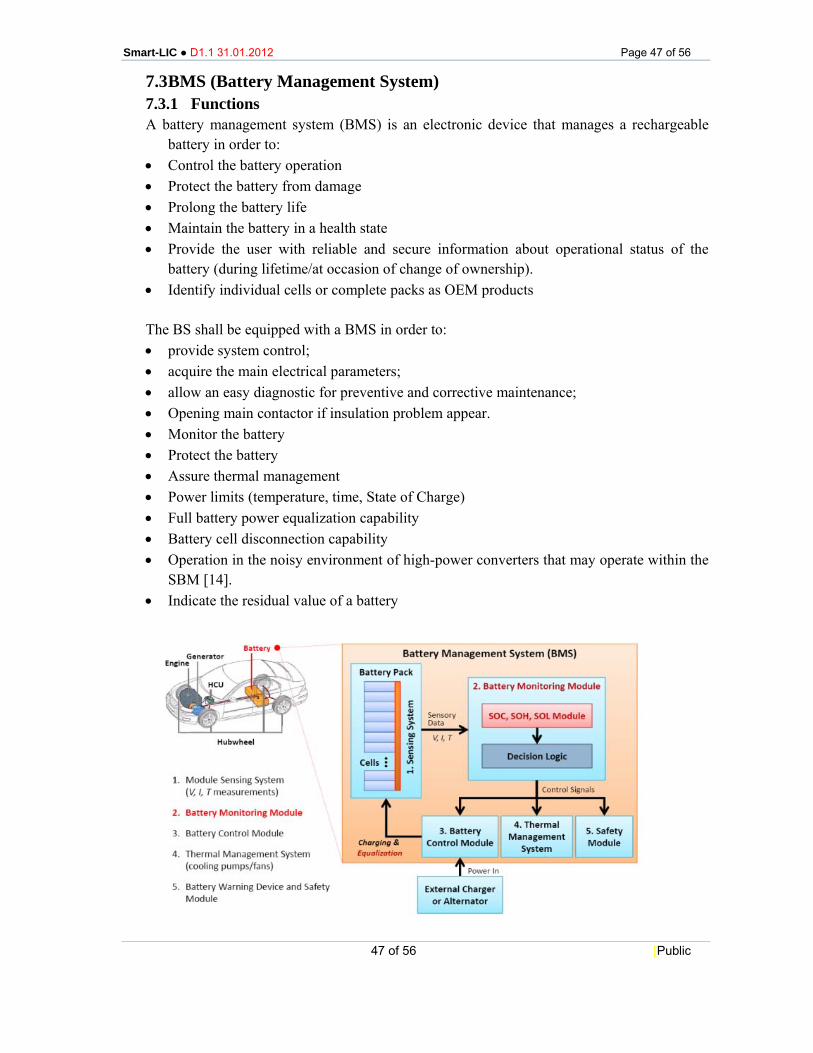
7.3 BMS (Battery Management System) 7.3.1 Functions A battery management system (BMS) is an electronic device that manages a rechargeable
battery in order to: • Control the battery operation • Protect the battery from damage • Prolong the battery life • Maintain the battery in a health state • Provide the user with reliable and secure information about operational status of the
battery (during lifetime/at occasion of change of ownership). • Identify individual cells or complete packs as OEM products The BS shall be equipped with a BMS in order to: • provide system control; • acquire the main electrical parameters; • allow an easy diagnostic for preventive and corrective maintenance; • Opening main contactor if insulation problem appear. • Monitor the battery • Protect the battery • Assure thermal management • Power limits (temperature, time, State of Charge) • Full battery power equalization capability • Battery cell disconnection capability • Operation in the noisy environment of high-power converters that may operate within the
SBM [14]. • Indicate the residual value of a battery
Smart-LIC ● D1.1 31.01.2012 Page 48 of 56
48 of 56 [Public
Figure 32. - BMS environment [source: Martin Klein: LG chem. Power, 2011 PHM conference BMS Workshop]
Signal female/male connector to be defined (at least IP 57 degree of protection is required
and automotive specs compliant). The BMS must provide: • monitoring of voltages, temperatures, current; • real time max admissible discharge and charge power; • SoC calculation; • SoH calculation; • SoL calculation; • Cell balancing. • Allow information to the driver (or an extract of the above defined data)
(especially for range estimation and –in case of resale- the residual value of the battery) • Robust design (automotive grade) • Thermal management • Fault detection and diagnostic • Safety • Low cost • Cells protection • Light volume The primary emphasis of BMS research is to extract maximum performance from
rechargeable batteries while minimizing degradation and extending lifetime. Specific research topics under BMS include:
• Physical and chemical basis of cell degradation; • State-of-charge estimation for various cell chemistries; • State-of-health estimation for various cell chemistries; • Remaining lifetime estimation for battery systems; • Cell, module and system-level performance monitoring; • “Fuel gauge” applications for primary and secondary batteries; • Innovative charge/discharge management and control systems at cell, module, and system
levels; • Battery usage monitoring for warranty assurance; • Range-extending control strategies; • Managing power demand from battery charging systems; • Cell monitoring and cell balancing management for certain chemistries; • Secure communication between cells and central unit.
7.3.2 BMS outcomes (title not clear) • SOx and Power Management are critical BMS functions; • To make the BMS affordable and to reduce the time to market, focus on the functions
most critical to enhancing cell performance and life;
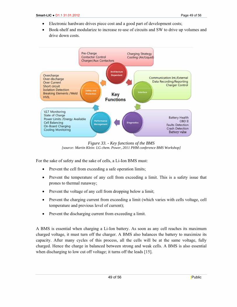
Smart-LIC ● D1.1 31.01.2012 Page 49 of 56
49 of 56 [Public
• Electronic hardware drives piece cost and a good part of development costs; • Book-shelf and modularize to increase re-use of circuits and SW to drive up volumes and
drive down costs.
Figure 33. - Key functions of the BMS
[source: Martin Klein: LG chem. Power, 2011 PHM conference BMS Workshop] For the sake of safety and the sake of cells, a Li-Ion BMS must:
• Prevent the cell from exceeding a safe operation limits;
• Prevent the temperature of any cell from exceeding a limit. This is a safety issue that prones to thermal runaway;
• Prevent the voltage of any cell from dropping below a limit;
• Prevent the charging current from exceeding a limit (which varies with cells voltage, cell temperature and previous level of current);
• Prevent the discharging current from exceeding a limit.
A BMS is essential when charging a Li-Ion battery. As soon as any cell reaches its maximum charged voltage, it must turn off the charger. A BMS also balances the battery to maximize its capacity. After many cycles of this process, all the cells will be at the same voltage, fully charged. Hence the charge in balanced between strong and weak cells. A BMS is also essential when discharging to low cut off voltage; it turns off the leads [15].
Smart-LIC ● D1.1 31.01.2012 Page 50 of 56
50 of 56 [Public
Figure 34. - BMS design strategies
[source: Martin Klein: LG chem. Power 2011, PHM conference BMS Workshop]
7.3.3 Communication protocol Data communication (battery bus SAE J1939 compliant) is realized here by means of CAN bus, at speed of 250 kb/s (as indication).
7.3.4 Communication interface Battery Module composed of battery itself, BMS and other components inside the module.
Internally: components need to withstand the environment; interface needs to be defined.
7.3.5 EMC The references and applicable standard is: 72/245/CEE – 2004/104/CE. The BS has to be designed to withstand and operate under internal and external electromagnetic noise. The BS has not to cause electromagnetic emission which could disturb or effect in any case operation mode of any devices surrounding.
7.3.6 Connectivity (mechanical / electrical) This aspect has to be compliant with standard automotive requirements. For the connector a water tightness of IP57 is required.
7.3.7 Temperature requirements (which voltage at what temperature?) The interface between BMS & air condition must allow maintenance of the voltage at the right level e.g. CAN identifier.
Smart-LIC ● D1.1 31.01.2012 Page 51 of 56
51 of 56 [Public
7.3.8 Memory requirements (what shall be stored / how long / for which purpose?)
Essential data needs to be stored in order to be able to evaluate the residual (monetary) value of a battery.
Data which will be stored can be the following: • Kilometer counter (“odometer), (very important data in order to avoid having a chance to
compare battery packs of different provider). • Battery energy flow counter • Number of charging cycles • Charging rates • Safety data • Vehicle parameters,
7.3.9 Black box (stored data, how long?) At the moment no black box functionality is specified.
7.3.10 Cryptography The need of encrypted communication has been taken into account, defining cryptological levels for tools, data storage and communication.
At the moment, encrypted communication exists.
In order to secure all the data, most part of the blocs (Batteries, BMS, Black Box, Interior display...) must include an encoded bus.
The cryptography will be managed by software.
State of Art BMS software can include the following functionalities:
• Automatic systems that link batteries for charging and isolate batteries for discharging;
• Simplicity of installation;
• Monitoring voltage of the vehicles batteries;
• Spike voltage protection to EFI and automotive computer systems;
• Ability to be installed into a large range of vehicles;
• Detection of counterfeit products.
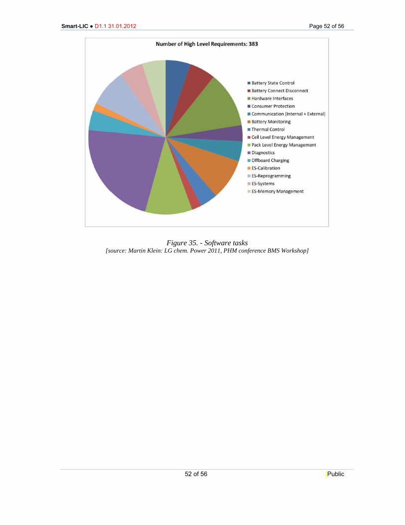
Smart-LIC ● D1.1 31.01.2012 Page 52 of 56
52 of 56 [Public
Figure 35. - Software tasks [source: Martin Klein: LG chem. Power 2011, PHM conference BMS Workshop]
Smart-LIC ● D1.1 31.01.2012 Page 53 of 56
53 of 56 [Public
8 CONCLUSIONS
The SMART-LIC Project addresses the development of a new Battery Management System Module for Fully Electric Vehicles, to be integrated into Lithium-Ion Cell.
In the frame of this goal, the present document contains the Deliverable 1.1, “Report detailing system specification and requirements”, related to Work Package 1 (WP1).
The characteristic application scenarios have been identified, on the basis of the State-of-the-Art on existing solutions for the addressed developments, and the over-all system requirements have been deducted, also on the basis of a dedicated questionnaire.
This resulted in definition of specifications for the cell balancing strategy, requirements for the communication/EMC and for the integration/packaging solutions.
Furthermore, the document contains the needed information about compliance with standard automotive, concerning safety requirements.
System specifications have been defined, in terms of electrical and mechanical requirements, and specific functions of Battery Management System have been addressed, in particular concerning communication.
The Deliverable D1.1 will be used as the general System Specification and requirements as a reference document for the following activities scheduled in the other Work Packages addressing developments of the BMS, in particular in WP2, Development of System Architecture and System Design.
8.1 Contribution to overall picture This document gives an overview about all issues (as far as identified) regarding:
• Battery pack (cells, cabling, fuses, contacts…);
• Integrated cooling system;
• BMS (Battery Management System);
• Battery system housing fixing parts.
Many items that concern components, modules, subassemblies, and communication are already discussed in the consortium of smart-LIC.
8.2 Relation to the state-of-the-art and progress beyond it The smart-LIC consortium has in this first document identified the state of the art and the actions that will be suitable. The State-of-Art regarding the BMS is one of the main issues for the success of the project.

Smart-LIC ● D1.1 31.01.2012 Page 54 of 56
54 of 56 [Public
8.3 Impacts to other WPs and Tasks This document and the work described herein will influence the definition of components. Thus, WP 1 is the first entrance for the outcome. It then influences directly the component and module work packages (WP2 and 5).
8.4 Contribution to demonstration (what aspects of the work that will be demonstrated
This work will contribute to the realisation of demonstrators and will be discussed in the next deliverable.
8.5 Other conclusions and lessons learned The BMS and communication are important issues. During the preparation ²of this document, it became obvious that these issues are often underestimated by the technical population. It is therefore even more important to increase the communication around these items in the consortium during the next phases of the project.
Furthermore it needs to be tracked what kind of problems occur during the introduction and operation phase of new BEV/PHEVs (i.e. Chevrolet Volt – post crash fires) in order to better underline the advantages of SmartLIC in this market.
Smart-LIC ● D1.1 31.01.2012 Page 55 of 56
55 of 56 [Public
9 REFERENCES NOTE: List and number all bibliographical references in 12-point Times New Roman, single spaced, at the end of the delivery report. When referenced in the text, enclose the citation number in square brackets, for example [1]. Where appropriate, include the name(s) of editors of referenced books.
[1.] RWTH – Szczechowicz, G4V – Grid for Vehicles – WP1.3 – Parameter Manual, 16.12.201;
[2.] IEA, RETRANS Project, “Opportunities for the Use of Renewable Energy in Road Trasport”, 2010
[3.] http://www.dges.de/alternative-antriebe/4.html - 01.05.2010., 05.05.2010;
[4.] Forschungsstelle für Energiewirtschaft e.V. Elektrofahrzeuge Elektrizitätswirtschaftliche Einbindung von Elektrostraßenfahrzeugen, Endbericht 2007;
[5.] ISE Fraunhofer, J. Link and others, Optimization Algorithms for the Charge Dispatch of Plug-in Vehicles Based on Variable Tariffs, Working Paper Sustainability and Innovation, No. S3/2010;
[6.] http://www.4sgroup.eu
[7.] J. D. Power & Associates, Drive Green 2020: More Hope than Reality? - Special Report, November 2010
[8.] Boston Consulting Group, Batteries for Electric Cars: Changelles, Opportunities and the Outlook to 2020, December 2010.
[9.] J. Fetzer, S. Butzmann, H. Fink (SB LiMotive), Li-Ion Batteries – for the Future of Mobility - 16.07.2009
[10.] Roland Berger, Powertrain 2020 - The Li-Ion Battery Value Chain – Trends and implications, 15 Internationaler Fachkongress Fortschritte in der Automobilelektronik, Ludwigsburg, 7. Juni 2011
[11.] BERR, Investigation into the Scope for the Transport Sector to Switch to Electric Vehicles and Plugin Hybrid Vehicles, 2008
[12.] Huigang Zhang, Xindi Yu & Paul V. Braun, Three-dimensional bi-continuous ultrafast-charge and -discharge bulk battery electrodes, Nature Nanotechnology 6, 277–281 (2011)
[13.] ERA_NET, NEO/EOS-LT Program (Energy Research Subsidy, Long-Term, New Energy Development)
[14.] Designing a new generalized BMS (John Chatzakis, Kostas Kalaitzakis, Nicholas C. Voulgaris, and Stefanos N. Manias, Senior Member, IEEE)
[15.] Davide Andrea, BMS for large Lithium-Ion Battery packs