Embed Size (px)
Citation preview
Proceedings 2018, 2, 478; doi:10.3390/ICEM18-05334 www.mdpi.com/journal/proceedings
Proceedings
Delaying Effect of Fatigue Crack Propagation by Single-Pulse Laser Irradiation † Masayuki Arai 1,*, Kenji Inada 2, Tomoki Morinaga 2, Kiyohiro Itoh 1, Hiroki Yokota 3 and Tatsuo Suidzu 3
1 Department of Mechanical Engineering, Tokyo University of Science, Tokyo 125-8585, Japan; [email protected]
2 Graduate School of Engineering, Tokyo University of Science, Tokyo 125-8585, Japan; [email protected] (K.I.); [email protected] (T.M.)
3 Thermal Spraying Technology R&D Laboratories, TOCALO Co., Ltd., Hyogo 125-8585, Japan; [email protected] (H.Y.); [email protected] (T.S.)
* Correspondence: [email protected]; Tel.: +81-3-5876-1823 † Presented at the 18th International Conference on Experimental Mechanics (ICEM18), Brussels, Belgium,
1–5 July 2018.
Published: 12 June 2018
Abstract: In this study, a single-pulse laser technique was applied to repair the cracked plate. The idea of this technique is based on delaying fatigue crack propagation by irradiating the area ahead of the crack tip by using a single-pulse laser with a high power of 1500 W. In order to verify the capability of this technique, fatigue tests were conducted on specimens with a hole on the center to induce fatigue cracks at the edge of the hole. A single-pulse laser irradiation was then applied ahead of this natural crack tip, and fatigue tests were subsequently conducted. The fatigue crack propagation behavior was monitored during cycling loading by using a digital microscope. It was confirmed that the crack irradiated by a pulse-laser is not almost progressed or is deflected around the irradiated area in subsequent cyclic loading after the repairing treatment, which means that the pulse laser technique could be located as an alternative to existing repairing techniques.
Keywords: fatigue crack propagation; delaying effect; single-pulse laser treatment; repair
1. Introduction
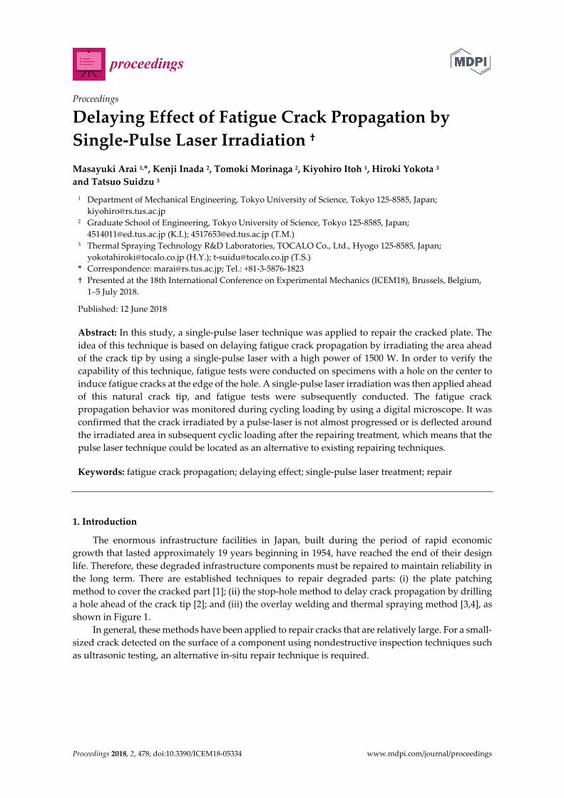
The enormous infrastructure facilities in Japan, built during the period of rapid economic growth that lasted approximately 19 years beginning in 1954, have reached the end of their design life. Therefore, these degraded infrastructure components must be repaired to maintain reliability in the long term. There are established techniques to repair degraded parts: (i) the plate patching method to cover the cracked part [1]; (ii) the stop-hole method to delay crack propagation by drilling a hole ahead of the crack tip [2]; and (iii) the overlay welding and thermal spraying method [3,4], as shown in Figure 1.
In general, these methods have been applied to repair cracks that are relatively large. For a small-sized crack detected on the surface of a component using nondestructive inspection techniques such as ultrasonic testing, an alternative in-situ repair technique is required.
Proceedings 2018, 2, 478 2 of 5
(a) (b) (c)
Figure 1. Current repair techniques used on damaged components. (a) Plate patching method; (b) Stop-hole method; (c) Overlay welding method.
In this study, a single-pulse laser technique was applied to repair the cracked plate. The idea of this technique is based on delaying fatigue crack propagation by irradiating the area ahead of the crack tip by using a single-pulse laser with a high power of 1500 W. To validate this technique, fatigue tests were conducted on the specimen with a hole at the center and an induced fatigue crack at the edge of the hole. A single-pulse laser irradiation was then applied ahead of this natural crack tip. The delaying effect due to laser irradiation was then evaluated via a detailed examination of fatigue crack propagation behavior. Additionally, the most suitable position for laser irradiation was investigated.
2. Feasibility Study of the Delaying Effect via Finite-Element Analysis
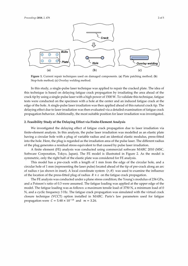
We investigated the delaying effect of fatigue crack propagation due to laser irradiation via finite-element analysis. In this analysis, the pulse laser irradiation was modelled as an elastic plate having a circular hole with a plug of variable radius and an identical elastic modulus, press-fitted into the hole. Here, the plug is regarded as the irradiation area of the pulse laser. The different radius of the plug generates a residual stress equivalent to that caused by pulse laser irradiation.
A finite element (FE) analysis was conducted using commercial software MARC 2010 (MSC. Software Corporation, Tokyo, Japan). The FE model is illustrated in Figure 2. As the model is symmetric, only the right half of the elastic plate was considered for FE analysis.
This model has a pre-crack with a length of 1 mm from the edge of the circular hole, and a circular hole of 1 mm (representing the laser pulse) located ahead of the tip of pre-crack along an arc of radius r (as shown in inset). A local coordinate system , was used to examine the influence of the location of the press-fitted plug of radius + on the fatigue crack propagation.
The FE analysis was conducted under a plane stress condition; the Young’s modulus of 236 GPa, and a Poisson’s ratio of 0.3 were assumed. The fatigue loading was applied at the upper edge of the model. The fatigue loading was as follows: a maximum tensile load of 3750 N, a minimum load of 0 N, and a cyclic frequency 3 Hz. The fatigue crack propagation was simulated with the virtual crack closure technique (VCCT) option installed in MARC. Paris’s law parameters used for fatigue propagation were = 5.48 × 10 and = 3.26.
Proceedings 2018, 2, 478 3 of 5
Figure 2. Finite element (FE) model.
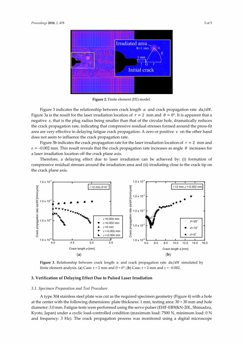
Figure 3 indicates the relationship between crack length and crack propagation rate / . Figure 3a is the result for the laser irradiation location of = 2 mm and = 0°. It is apparent that a negative , that is the plug radius being smaller than that of the circular hole, dramatically reduces the crack propagation rate, indicating that compressive residual stresses formed around the press-fit area are very effective in delaying fatigue crack propagation. A zero or positive on the other hand does not seem to influence the crack propagation rate.
Figure 3b indicates the crack propagation rate for the laser irradiation location of = 2 mm and =−0.002 mm. This result reveals that the crack propagation rate increases as angle increases for a laser irradiation location off the crack plane axis.
Therefore, a delaying effect due to laser irradiation can be achieved by: (i) formation of compressive residual stresses around the irradiation area and (ii) irradiating close to the crack tip on the crack plane axis.
(a) (b)
Figure 3. Relationship between crack length and crack propagation rate / simulated by finite element analysis. (a) Case: r = 2 mm and θ = 0°; (b) Case: r = 2 mm and ε = −0.002.
3. Verification of Delaying Effect Due to Pulsed Laser Irradiation
3.1. Specimen Preparation and Test Procedure
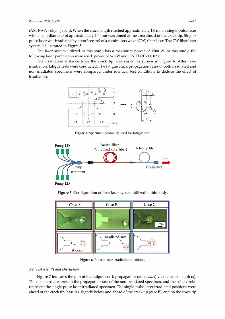
A type 304 stainless steel plate was cut as the required specimen geometry (Figure 4) with a hole at the center with the following dimensions: plate thickness: 1 mm, testing area: 30 × 30 mm and hole diameter: 3.0 mm. Fatigue tests were performed using the servo pulser (EHF-EB50kN-20L, Shimadzu, Kyoto, Japan) under a cyclic load-controlled condition (maximum load: 7500 N, minimum load: 0 N and frequency: 3 Hz). The crack propagation process was monitored using a digital microscope
1.0 x 10⁻⁶
1.0 x 10⁻⁵
1.0 x 10⁻⁴
1.0 x 10⁻³
ε =0.004 mmε =0.002 mmε =0 mmε =-0.002 mmε =-0.004 mm
4.0 4.5 5.0 5.5
Cra
ck p
ropa
gatio
n ra
te d
a/dN
[mm
/cyc
le]
Crack length a [mm]
r =2 mm,θ =0 °
1.0 x 10⁻⁶
1.0 x 10⁻⁵
1.0 x 10⁻⁴
1.0 x 10⁻³
1.0 x 10⁻²
4.0 6.0 8.0 10.0 12.0 14.0 16.0
θ =20°
θ =10°
θ =0°
Cra
ck p
ropa
gatio
n ra
te d
a/dN
[mm
/cyc
le]
Crack length a [mm]
r =2 mm,ε =-0.002 mm
Proceedings 2018, 2, 478 4 of 5
(ARTRAY, Tokyo, Japan). When the crack length reached approximately 1.0 mm, a single-pulse laser with a spot diameter of approximately 1.0 mm was aimed at the area ahead of the crack tip. Single-pulse laser was irradiated by on/off control of a continuous wave (CW) fiber laser. The CW fiber laser system is illustrated in Figure 5.
The laser system utilized in this study has a maximum power of 1500 W. In this study, the following laser parameters were used: power of 675 W and ON TIME of 0.02 s.
The irradiation distance from the crack tip was varied as shown in Figure 6. After laser irradiation, fatigue tests were conducted. The fatigue crack propagation rates of both irradiated and non-irradiated specimens were compared under identical test conditions to deduce the effect of irradiation.
Figure 4. Specimen geometry used for fatigue test.
Figure 5. Configuration of fiber laser system utilized in this study.
Figure 6. Pulsed laser irradiation positions.
3.2. Test Results and Discussion
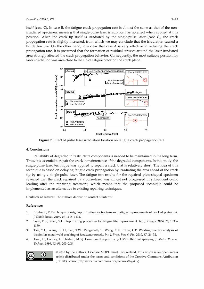
Figure 7 indicates the plot of the fatigue crack propagation rate (da/dN) vs. the crack length (a). The open circles represent the propagation rate of the non-irradiated specimen, and the solid circles represent the single-pulse laser irradiated specimen. The single-pulse laser irradiated positions were ahead of the crack tip (case A), slightly below and ahead of the crack tip (case B), and on the crack tip
Proceedings 2018, 2, 478 5 of 5
itself (case C). In case B, the fatigue crack propagation rate is almost the same as that of the non-irradiated specimen, meaning that single-pulse laser irradiation has no effect when applied at this position. When the crack tip itself is irradiated by the single-pulse laser (case C), the crack propagation rate is slightly increased, from which we may conclude that the irradiation caused a brittle fracture. On the other hand, it is clear that case A is very effective in reducing the crack propagation rate. It is presumed that the formation of residual stresses around the laser-irradiated area strongly affected the crack propagation behavior. Consequently, the most suitable position for laser irradiation was area close to the tip of fatigue crack on the crack plane.
Figure 7. Effect of pulse laser irradiation location on fatigue crack propagation rate.
4. Conclusions
Reliability of degraded infrastructure components is needed to be maintained in the long term. Thus, it is essential to repair the crack in maintenance of the degraded components. In this study, the single-pulse laser technique was applied to repair a crack that is relatively short. The idea of this technique is based on delaying fatigue crack propagation by irradiating the area ahead of the crack tip by using a single-pulse laser. The fatigue test results for the repaired plate-shaped specimen revealed that the crack repaired by a pulse-laser was almost not progressed in subsequent cyclic loading after the repairing treatment, which means that the proposed technique could be implemented as an alternative to existing repairing techniques.
Conflicts of Interest: The authors declare no conflict of interest.
References
1. Brighenti, R. Patch repair design optimization for fracture and fatigue improvements of cracked plates. Int. J. Solids Struct. 2007, 44, 1115–1131.
2. Song, P.S.; Shieh, Y.L. Stop drilling procedure for fatigue life improvement. Int. J. Fatigue 2004, 26, 1333–1339.
3. Tsai, Y.L.; Wang, Li. H.; Fan, T.W.; Ranganath, S.; Wang, C.K.; Chou, C.P. Welding overlay analysis of dissimilar metal weld cracking of feedwater nozzle. Int. J. Press. Vessel. Pip. 2010, 87, 26–32.
4. Tan, J.C.; Looney, L.; Hashmi, M.S.J. Component repair using HVOF thermal spraying. J. Mater. Process. Technol. 1999, 92–93, 203–208.
© 2018 by the authors. Licensee MDPI, Basel, Switzerland. This article is an open access article distributed under the terms and conditions of the Creative Commons Attribution (CC BY) license (http://creativecommons.org/licenses/by/4.0/).