Embed Size (px)
Citation preview
Delaware Department of Transportation
Bridge Management Section
BRIDGE ELEMENT INSPECTION MANUAL
2021 Edition

This page intentionally left blank.
DOUGLAS S. ATKINDigitally signed by DOUGLAS S. ATKIN Date: 2021.04.26 17:00:19 -04'00'

This page intentionally left blank.
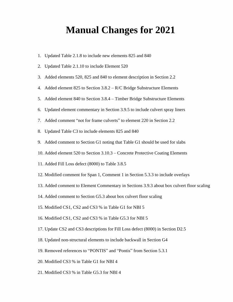
Manual Changes for 2021
1. Updated Table 2.1.8 to include new elements 825 and 840
2. Updated Table 2.1.10 to include Element 520
3. Added elements 520, 825 and 840 to element description in Section 2.2
4. Added element 825 to Section 3.8.2 – R/C Bridge Substructure Elements
5. Added element 840 to Section 3.8.4 – Timber Bridge Substructure Elements
6. Updated element commentary in Section 3.9.5 to include culvert spray liners
7. Added comment “not for frame culverts” to element 220 in Section 2.2
8. Updated Table C3 to include elements 825 and 840
9. Added comment to Section G1 noting that Table G1 should be used for slabs
10. Added element 520 to Section 3.10.3 – Concrete Protective Coating Elements
11. Added Fill Loss defect (8000) to Table 3.8.5
12. Modified comment for Span 1, Comment 1 in Section 5.3.3 to include overlays
13. Added comment to Element Commentary in Sections 3.9.3 about box culvert floor scaling
14. Added comment to Section G5.3 about box culvert floor scaling
15. Modified CS1, CS2 and CS3 % in Table G1 for NBI 5
16. Modified CS1, CS2 and CS3 % in Table G5.3 for NBI 5
17. Update CS2 and CS3 descriptions for Fill Loss defect (8000) in Section D2.5
18. Updated non-structural elements to include backwall in Section G4
19. Removed references to “PONTIS” and “Pontis” from Section 5.3.1
20. Modified CS3 % in Table G1 for NBI 4
21. Modified CS3 % in Table G5.3 for NBI 4

This page intentionally left blank.
DelDOT Bridge Element Inspection Manual Bridge Management Section I 2/1/21
TABLE OF CONTENTS
TABLE OF CONTENTS……………………………………………………………………………….....I
INTRODUCTION………………………..……………………………………………………………….1
SECTION 1: BACKGROUND
1.1—CONDITION ASSESSMENT PHILOSOPHY: MULTIPATH AND DEFECT CONCEPTS.....3
1.2—NATIONAL BRIDGE ELEMENTS (NBE’s)………………………………………………......3
1.3—BRIDGE MANAGEMENT ELEMENTS (BME’s) ................................................................... 3
1.4—AGENCY-DEVELOPED ELEMENTS (ADE’s) ....................................................................... 4
1.5—HOW TO USE THIS MANUAL ................................................................................................ 4
1.6—ORGANIZATION ...................................................................................................................... 5
SECTION 2: ELEMENT SELECTION
2.1—ELEMENT LOCATION MATRIX ............................................................................................ 7
2.1.1 —Railings .............................................................................................................................. 7
2.1.2 —Curbs, Medians, Drains and Sidewalks ............................................................................. 7
2.1.3 —Approach Slabs .................................................................................................................. 7
2.1.4 —Decks and Slabs ................................................................................................................. 8
2.1.5 —Joints .................................................................................................................................. 8
2.1.6 —Superstructure .................................................................................................................... 9
2.1.7 —Bearings ............................................................................................................................. 9
2.1.8 —Substructure ..................................................................................................................... 10
2.1.9 —Culverts ............................................................................................................................ 11
2.1.10—Wearing Surfaces, Protective Coatings and Reinforcing Steel Protective Systems........ 11
2.1.11—Smart Flags .................................................................................................................... 12
2.1.12—Movable Bridge Elements ............................................................................................. 12
2.2—ELEMENT DESCRIPTIONS .................................................................................................. 13
SECTION 3: DETAILED ELEMENT CONDITION STATE DESCRIPTIONS
3.1—BRIDGE RAIL ELEMENTS .................................................................................................. 30
3.1.1—Metal Bridge Railing ...................................................................................................... 30
3.1.2—Reinforced Concrete Bridge Railing………………………………………………….....32
3.1.3—Timber Bridge Railing .................................................................................................... 34
3.1.4—Masonry Bridge Railing. ................................................................................................ 36
3.1.5—Other Bridge Railing ...................................................................................................... 38
DelDOT Bridge Element Inspection Manual Bridge Management Section II 2/1/21
3.2—BRIDGE CURB, MEDIAN, SIDEWALK & DRAINS .............................................................. 40
3.2.1—Reinforced Concrete Bridge Curb, Median & Sidewalk .................................................. 40
3.2.2—Steel Bridge Curb, Median & Sidewalk .......................................................................... 42
3.2.3—Timber Bridge Curb & Sidewalk .................................................................................... 44
3.2.4—Masonry Bridge Curb, Median & Sidewalk .................................................................... 46
3.2.5—Drains ............................................................................................................................. 48
3.3— APPROACH SLAB BRIDGE ELEMENTS ........................................................................... 50
3.3.1—Reinforced Concrete Approach Slab Bridge Element ..................................................... 50
3.1.2—Prestressed Concrete Approach Slab Bridge Element ……………………………..…...52
3.4—DECK/SLAB BRIDGE ELEMENTS ....................................................................................... 54
3.4.1—Reinforced Concrete Deck/Slab Bridge Elements .......................................................... 54
3.4.2—Prestressed Concrete Deck/Slab Bridge Elements .......................................................... 56
3.4.3—Timber Deck/Slab Bridge Elements ............................................................................... 58
3.4.4—Steel Deck Bridge Elements ........................................................................................... 60
3.4.5—Other Deck/Slab Bridge Elements .................................................................................. 62
3.4.6—A/C Overlay Bridge Element ......................................................................................... 64
3.5—BRIDGE JOINT ELEMENTS ................................................................................................. 66
3.5.1—Bridge Joints w/ Gland ................................................................................................... 66
3.5.2—Bridge Joints w/o Gland ................................................................................................. 68
3.5.3—Bridge Joints w/ Pourable of Asphaltic Seal .................................................................. 70
3.5.4—Bridge Joints Other ......................................................................................................... 72
3.6—BRIDGE SUPERSTRUCTURE ELEMENTS .......................................................................... 74
3.6.1—Steel Bridge Superstructure Elements ............................................................................. 74
3.6.2—Reinforced Concrete Bridge Superstructure Elements ................................................... 76
3.6.3—Prestressed Concrete Bridge Superstructure Elements ................................................... 78
3.6.4—Timber Bridge Superstructure Elements ........................................................................ 80
3.6.5—Masonry Bridge Superstructure Elements ...................................................................... 82
3.6.6—Other Bridge Superstructure Elements ........................................................................... 84
3.7—BRIDGE BEARING ELEMENTS ............................................................................................ 86
3.7.1—Bridge Bearings w/ an Elastomer ................................................................................... 86
3.7.2—Bridge Bearings w/o an Elastomer ................................................................................. 88
3.7.3—Other Bridge Bearing ..................................................................................................... 90
3.8—BRIDGE SUBSTRUCTURE ELEMENTS .............................................................................. 92
3.8.1—Steel Bridge Substructure Elements ............................................................................... 92
3.8.2—Reinforced Concrete Bridge Substructure Elements ...................................................... 94
3.8.3—Prestressed Concrete Bridge Substructure Elements ...................................................... 96
DelDOT Bridge Element Inspection Manual Bridge Management Section III 2/1/21
3.8.4—Timber Bridge Substructure Elements ........................................................................... 98
3.8.5—Masonry Bridge Substructure Elements ....................................................................... 100
3.8.6—Mechanically Stabilized Earth Wall Bridge Substructure Elements ............................. 102
3.8.7—Other Bridge Substructure Elements ............................................................................ 104
3.9—BRIDGE CULVERT ELEMENTS ......................................................................................... 106
3.9.1—Steel Culvert Elements ................................................................................................. 106
3.9.2—Aluminum Culvert Elements ........................................................................................ 108
3.9.3—Reinforced Concrete Culvert Elements ......................................................................... 110
3.9.4—Masonry Culvert Element............................................................................................. 112
3.9.5—Other Culvert Element .................................................................................................. 114
3.9.6—Sacked Concrete Wall .................................................................................................. 116
3.10—WEARING SURFACES, PROTECTIVE COATINGS AND CONCRETE
REINFORCING STEEL PROTECTIVE SYSTEMS .......................................................... 118
3.10.1—Wearing Surface Elements .......................................................................................... 118
3.10.2—Steel Protective Coating Elements .............................................................................. 120
3.10.3—Concrete Protective Coating Element ......................................................................... 122
3.11—SMART FLAG ELEMENTS ................................................................................................ 124
3.11.1—Soffit Smart Flag ........................................................................................................ 124
3.11.2—Erosion Smart Flag ..................................................................................................... 126
3.12—MOVABLE BRIDGE ELEMENTS ...................................................................................... 128
3.12.1—Movable Bridge Electrical System Element ............................................................... 128
3.12.2—Movable Bridge Mechanical System Element............................................................ 130
SECTION 4: ELEMENT FACTORS
4.1—ENVIRONMENTAL FACTORS (SERVICE CONDITIONS) ............................................ 133
4.2—ELEMENT SCALE FACTORS ............................................................................................ 135
4.2.1—Scale Factor Computations ............................................................................................ 135
4.2.2—Element Scale Factor Table………………………………………………………..… ..137
SECTION 5: ELEMENT SELECTION, QUANTITY CALCULATION AND INSPECTION
GUIDANCE
5.1—ELEMENT SELECTION ...................................................................................................... 139
5.1.1—Bridge Railing ............................................................................................................... 139
5.1.2—Curbs & Sidewalks ....................................................................................................... 139
5.1.3—Truss Elements ............................................................................................................. 139
5.1.4—Substructure Elements .................................................................................................. 139
DelDOT Bridge Element Inspection Manual Bridge Management Section IV 2/1/21
5.2—ELEMENT QUANTITY CALCULATION ............................................................................. .140
5.2.1—Estimating Total Quantities ......................................................................................... .140
5.2.2—Convention for Quantities...…………………………………………………………...140
5.2.3—Element Quantity Calculation Examples...…………………………………………......141
5.2.4—Steel Protective Coating Element Quantity Calculation...…………………………........144
5.2.4.1— Steel Protective Coating Quantity Calculation for Other Elements ............. …….144
5.2.4.2— Steel Protective Coating Element Quantity Calculation Examples .............. …….145
5.3—INSPECTION GUIDANCE ................................................................................................... .146
5.3.1—General ....................................................................................................................... ..146
5.3.2—Inspection Orientation….....…………………………………………………………….146
5.3.3—Multi-Span Orientation………………......…………………………………………….146
5.3.4—Element Condition State Assignment Guidance………………………..……………...147
5.3.5—Concrete Crack Size Definitions ……………………………………………………….147
5.4—EXAMPLES OF BEARING TYPES ..................................................................................... 148
5.4.1—Elastomeric Bearing, Element No 310 .......................................................................... 148
5.4.1.1—Elastomeric Bearing w/o Teflon Plates .......................................................... ……148
5.4.1.2—Elastomeric Bearing w/ Teflon Plates ............................................................ ……148
5.4.1.3—Isolation Bearing ............................................................................................ ……149
5.4.2—Movable Bearing, Element No 311 ............................................................................... 149
5.4.2.1—Roller & Rocker Nests ................................................................................... ……149
5.4.2.2—Sliding Plate Bearing ..................................................................................... ……150
5.4.2.3—Rocker Bearing .............................................................................................. ……151
5.4.2.4—Spherical Bearing ........................................................................................... ……151
5.4.3—Fixed (Pinned) Bearing, Element No 313 ..................................................................... 152
5.4.4—Pot Bearing, Element No 314 ........................................................................................ 152
5.4.5—Disc Bearing, Element No 315 ...................................................................................... 153
5.5—EXAMPLES OF JOINT TYPES ............................................................................................ 154
5.5.1—Strip Seal Expansion, Element No 300 ......................................................................... 154
5.5.1.1—Traditional Strip Seal Joint ............................................................................ ……154
5.5.1.2—Elastomeric Flex-Type Joint (Sheet Seal Joint) ............................................. ……154
5.5.2—Plank Seal Joint (Waboflex), Element No 306 .............................................................. 155
5.5.3—Assembly Joint w/ Seal Element, Element No 303 ....................................................... 155
5.5.4—Pourable Joint Seal, Element No 301 ............................................................................ 156
5.5.5—Compression Joint Seal, Element No 302 ..................................................................... 156
DelDOT Bridge Element Inspection Manual Bridge Management Section V 2/1/21
5.5.6—Assembly Joint w/o Seal, Element No 305………………………………………..157
5.5.6.1—Sawtooth Plate Joint………………………………………………………..157
5.5.6.2—Finger Plate Joint…………………………………………………………..157
5.5.6.3—Sliding Plate Joint………………………………………………………….157
5.5.7—Open Expansion Joint, Element No 304…………………………………………..158
5.5.8—Asphaltic Plug Joint, Element No 809……………………………………………..158
APPENDIX A: AGENCY-DEFINED ELEMENTS (ADE’s)……………………………………….….....159
A1—AGENCY-DEFINED SUBSETS OF THE NATIONAL BRIDGE ELEMENTS...................159
A2—AGENCY-DEFINED SUBSETS OF THE BRIDGE MANAGEMENT ELEMENTS ..........159
A3—INDEPENDENT AGENCY-DEFINED ELEMENTS............................................................160
A4—DELDOT DEVELOPED ADE’S…………............................................................................161
A5—COMBINED PONTIS CORE & DELDOT NON-CORE ELEMENTS.................................163
A6—CONVERTED PONTIS SMART FLAG ELEMENTS..........................................................164
APPENDIX B: INSPECTION EXAMPLES ..........................................................................................165
B1—TIMBER BRIDGE ..................................................................................................................165
B1.1—Element Quantities ..........................................................................................................165
B1.1.1—Deck .......................................................................................................................165
B1.1.2—Superstructure ........................................................................................................166
B1.1.3—Substructure ...........................................................................................................166
B1.2—Element Condition States ................................................................................................166
B1.2.1—Defect #1, Timber Open Girder/Beam (Element 111) ...........................................166
B1.2.2—Defect #2, Timber Pier Cap (Element 235)............................................................167
B1.2.3—Defect #3, Timber Pile (Element 228) ...................................................................167
B1.2.4—Defect #4, Metal Bridge Railing (Element 330) ....................................................167
B1.3—Element Quantity and Condition State Summary ...........................................................168
B2—PRESTRESSED CONCRETE GIRDER BRIDGE ................................................................169
B2.1—Element Quantities ..........................................................................................................169
B2.1.1—Deck .......................................................................................................................169
B2.1.2—Superstructure ........................................................................................................169
B2.1.3—Substructure ...........................................................................................................170
B2.2—Element Condition States ................................................................................................170
B2.2.1—Defect #1, Reinforced Concrete Deck (Element 12)..............................................170
B2.2.2—Defect #2, Reinforced Concrete Deck (Element 12)..............................................170
DelDOT Bridge Element Inspection Manual Bridge Management Section VI 2/1/21
B2.2.3—Defect #3, Reinforced Concrete Deck (Element 12)..............................................171
B2.2.4—Defect #4, Compression Joint Seal (Element 302) & R/C Deck (Element 12)….171
B2.2.5—Defect #5, Reinforced Concrete Pier Cap (Element 234) ......................................171
B2.2.6—Defect #6, Reinforced Concrete Pier Cap (Element 234) ......................................172
B2.2.7—Defect #7, Reinforced Concrete Column (Element 205) .......................................172
B2.3—Element Quantity and Condition State Summary ...........................................................174
B3—STEEL TRUSS BRIDGE .......................................................................................................175
B3.1—Element Quantities ..........................................................................................................175
B3.1.1—Deck……………………………………………………. .....................................175
B3.1.2—Superstructure………………………………………….. ......................................176
B3.1.3—Substructure……………………………………………........................................176
B3.2—Element Condition States ................................................................................................176
B3.2.1—Defect #1, Reinforced Concrete Deck (Element 12)… .........................................177
B3.2.2—Defect #2, Steel Truss (Element 120).....................................................................177
B3.2.3—Defect #3, Steel Truss (Element 120), Steel Gusset Plate (Element 162),
and Steel Protective Coating (Element 515).......................................................177
B3.2.4—Defect #4, Steel Floor Beam (Element 152) and Steel Protective Coating
(Element 515)...................................................................................................178
B3.2.5—Defect #5, Steel Stringer (Element 113).................................................................178
B3.2.6—Defect #6, Steel Stringer (Element 113)..................................................................179
B3.2.7—Defect #7, Pier Wall (Element 210).........................................................................179
B3.3—Element Quantity and Condition State Summary ...........................................................180
B4—SINGLE SPAN STEEL MULTI-GIRDER BRIDGE.............................................................183
B4.1—Element Quantities ..........................................................................................................183
B4.1.1—Deck/Approaches……………………………………………………. ..................183
B4.1.2—Superstructure………………………………………….. ......................................184
B4.1.3—Substructure……………………………………………........................................184
B4.2—Element Condition States ................................................................................................185
B4.2.1—Defect #1, Reinforced Concrete Deck (Element 12).............................................185
B4.2.2—Defect #2, R.C. Approach Slab (Element 321)......................................................185
B4.2.3—Defect #3, Steel Open Girder/Beam (107) & Steel Protective Coating (515).......185
B4.2.4—Defect #4, Elastomeric Bearing (Element 310)……………………………….....186
B4.2.5—Defect #5, Concrete Encasement (Element 816)...................................................187
B4.2.6— Defect #6, Reinforced Concrete Abutment (Element 215)...................................187
B4.3—Element Quantity and Condition State Summary ...........................................................188
DelDOT Bridge Element Inspection Manual Bridge Management Section VII 2/1/21
B5—SINGLE SPAN ADJACENT PRESTRESSED CONCRETE BOX BEAM
BRIDGE..................................................................................................................................189
B5.1—Element Quantities ..........................................................................................................189
B5.1.1—Deck/Approaches……………………………………………………. .................189
B5.1.2—Superstructure………………………………………….. ......................................190
B5.1.3—Substructure…………………………………………….......................................190
B5.2—Element Condition States ................................................................................................190
B5.2.1—Defect #1, Reinforced Concrete Deck (Element 12).............................................190
B5.2.2— Defect #2, Wingwalls – Reinforced Concrete (Element 890)..............................190
B5.3—Element Quantity and Condition State Summary ...........................................................191
B6—SINGLE BARREL REINFORCED CONCRETE BOX CULVERT WITH FILL...............193
B6.1—Element Quantities ..........................................................................................................193
B6.1.1—Culvert………….……………………………………………………. ................193
B6.2—Element Condition States ................................................................................................193
B6.2.1—Defect #1, Reinforced Concrete Culvert (Element 845).......................................193
B6.2.2— Defect #2, Wingwalls – Reinforced Concrete (Element 890)..............................194
B6.3—Element Quantity and Condition State Summary ...........................................................194
APPENDIX C: ELEMENT GROUPINGS..............................................................................................195
C1—NATIONAL BRIDGE ELEMENTS........................................................................................196
C2—BRIDGE MANAGEMENT ELEMENTS ....... …………………………………………....197
C3—AGENCY-DEFINED ELEMENTS........................................................................................198
APPENDIX D: MATERIALS AND DEFECTS BY MATERIAL TYPE ..............................................199
D1—DEFECT DEFINITIONS AND MATERIALS .......................................................................199
D2—MATERIALS AND DEFECT CONDITION STATE DESCRIPTIONS ..............................204
D2.1—Steel & Aluminum (100)................................................................................................204
D2.2—Prestressed Concrete (300)..............................................................................................206
D2.3—Reinforced Concrete (400)..............................................................................................208
D2.4—Timber (500) ...................................................................................................................210
D2.5—Other Materials (600)......................................................................................................212
D2.6—Masonry (650).................................................................................................................216
D2.7—Wearing Surfaces (800) ..................................................................................................218
D2.8—Concrete Reinforcing Steel Protective Systems (820) ....................................................218
DelDOT Bridge Element Inspection Manual Bridge Management Section VIII 2/1/21
D2.9—Steel Protective Coatings (850).......................................................................................219
D2.10—Concrete Protective Coatings (880) ..............................................................................220
APPENDIX E: MATERIALS AND FEASIBLE ACTIONS BY MATERIAL TYPE .......................221
E1—STEEL & ALUMINUM (100) ................................................................................................221
E2—PRESTRESSED CONCRETE (300) .......................................................................................221
E3—REINFORCED CONCRETE (400) ........................................................................................222
E4—TIMBER (500) ........................................................................................................................222
E5—OTHER MATERIALS (600) ..................................................................................................222
E6—MASONRY (650) ....................................................................................................................222
E7—WEARING SURFACES (800) ................................................................................................223
E8—CONCRETE REINFORCING STEEL PROTECTIVE SYSTEMS (820)..............................223
E9—STEEL PROTECTIVE COATINGS (850) .............................................................................223
E10—CONCRETE PROTECTIVE COATINGS (880)...................................................................223
APPENDIX F: MAXIMO MAINTENANCE REQUESTS ....................................................................225
F1—MAXIMO PRIORITY 3 MAINTENANCE… ........................................................................225
F2—MAXIMO PRIORITY 2 MAINTENANCE… ........................................................................225
F3—MAXIMO PRIORITY 1 MAINTENANCE… ........................................................................225
F4—GENERAL GUIDANCE………………….… ........................................................................226
F5—MAXIMO FUNCTION CODES………………….… ............................................................226
F6—BRIDGE POSTING SIGNS………………….… ...................................................................228
APPENDIX G: GUIDANCE FOR NBI CONDITION RATING ASSIGNMENTS .............................229
G1—GENERAL CONDITION RATING GUIDANCE .................................................................229
G2—DECK CONDITION RATING GUIDANCE .........................................................................230
G2.1—Bare Concrete Decks .....................................................................................................230
G2.2—Concrete Decks w/ Overlay............................................................................................231
G3—SUPERSTRUCTURE CONDITION RATING GUIDANCE ................................................232
G3.1—Pre-stressed Concrete Superstructure .............................................................................232
G4—SUBSTRUCTURECONDITION RATING GUIDANCE ......................................................233
G5—CULVERT CONDITION RATING GUIDANCE ..................................................................233
G5.1—Small Span Metal Pipe Culverts.....................................................................................233
G5.2—Large Span Metal Pipe Culverts.....................................................................................234
G5.3—R/C Culverts……………………...................................................................................235
DelDOT Bridge Element Inspection Manual Bridge Management Section 1 2/1/21
INTRODUCTION
The proper assessment of the condition of bridge elements is the cornerstone of sound bridge
management. The introduction of element inspection condition methods in the early 1990s
represented a significant advancement in bridge inspection practice and has been adopted by the vast
majority of the state transportation departments in the United States. Bridge owners nationwide have
recognized the benefits of detailed condition assessments through the use of the raw inspection
information, expanded performance measures, and bridge management system deterioration
forecasting and evaluation. As the use of element-level inspection techniques has proliferated, the
need for updates and enhancements to the standard element specification has been identified. This
manual incorporates improvements through changes in the measurement units of decks and slabs,
the development of a wearing surface element, the standardization of the number of element states,
and the development of protective coating elements for concrete and steel, as well as deck
protection systems. Elements constructed of innovative materials are also identified. The goal of this
manual is to completely capture the condition of bridges in a simple, effective way that can be
standardized across the nation while providing the flexibility to be adapted to both large- and small-
agency settings.
This manual is not intended to supplant proper bridge and element inspection training or the
exercise of engineering judgment by the inspector or professional engineer.

DelDOT Bridge Element Inspection Manual Bridge Management Section 2 2/1/21
DelDOT Bridge Element Inspection Manual Bridge Management Section 3 2/1/21
SECTION 1:
BACKGROUND
1.1—CONDITION ASSESSMENT PHILOSOPHY: MULTIPATH AND DEFECT CONCEPTS
This manual is based off the AASHTO Manual for Bridge Element Inspection and builds on the
element-level condition assessment methods developed in the AASHTO Guide for Commonly
Recognized Structural Elements. Improvements have been made to fully capture the condition of the
elements by reconfiguring the element language to utilize multiple distress paths within the defined
condition states. The multipath distress language provides the means to fully incorporate all
possible defects within the overall condition assessment of the element. The overall condition of
an element can be utilized in this aggregate form, or broken down into specific defects present as
desired by the agency for Bridge Management System (BMS) use.
This manual provides a comprehensive set of bridge elements that is designed to be flexible in
nature to satisfy the needs of DelDOT’s Bridge Inspection Program and bridge inventory. The
complete set of elements captures the components necessary for an agency to manage all aspects of the
bridge inventory utilizing the full capability of a BMS.
The element set presented within includes two element types identified as National Bridge Elements
(NBE’s) and Bridge Management Elements (BME’s). The combination of these two element types
comprise the full AASHTO element set. All of the elements, whether they are NBE’s or BME’s, have
the same general condition assessment characteristics:
1. Standard number of condition states is four.
2. The standard condition states are good, fair, poor, and severe general descriptions.
3. Units of measure are length in feet, area in square feet, and each for enumerated elements.
1.2 —NATIONAL BRIDGE ELEMENTS (NBE’s)
The National Bridge Elements represent the primary structural components of bridges necessary
to determine the overall condition and safety of the primary load carrying members. The NBE’s are a
refinement of the deck, superstructure, substructure, and culvert condition ratings defined in the
Federal Highway Administration’s Recording and Coding Guide for the Structure Inventory and
Appraisal of the Nation’s Bridges. Additional elements included in this section are bridge rail and
bearings. The NBE’s are designed to remain consistent from agency to agency across the country
in order to facilitate and standardize the capture of bridge element conditions at the national level. In
order to capture the diversity of new element design types and materials, many elements in this
category have an “other” element type defined.
1.3—BRIDGE MANAGEMENT ELEMENTS (BME’s)
Bridge Management Elements include components of bridges such as joints, wearing surfaces, and
protective coating systems and deck/slab protection systems that are typically managed by agencies
utilizing Bridge Management Systems. The BME’s are defined with a recommended set of
condition assessment language that can be modified to suit the agencies’ needs as these elements
are not intended to be utilized for the purposes of national policy-making. The BME’s defined within
this manual were purposefully left fairly general in nature to provide the flexibility to develop
DelDOT Bridge Element Inspection Manual Bridge Management Section 4 2/1/21
agency- specific elements that best suit the local bridge management practices. Agencies may choose
to develop additional BME’s as necessary following the agency-developed element conventions
discussed in Appendix A. When considering additional elements, the agency should consider such
factors as element performance, deterioration rates, feasible actions, and preservation costs, as well
as the practical considerations of training and inspection costs.
1.4—AGENCY-DEVELOPED ELEMENTS (ADE’s)
The elements presented within provide the flexibility for an agency to define custom elements in
accordance with the defined element framework that may be sub-elements of NBE’s or BME’s, or
may be agency-defined elements without ties to the elements defined in this manual.
By defining a comprehensive set of bridge elements necessary for robust bridge management and
the minimum set of elements necessary to assess the condition of primary components of bridges,
this manual provides a flexible element set that can be tailored to the needs of all agencies. The
identification numbers 800 and above are used in this manual for ADE’s.
1.5—HOW TO USE THIS MANUAL
Bridge inspection based on this manual consists of defining the elements (pieces of the bridge) and
total quantities that exist at each bridge. The condition of each element is determined by performing a
field inspection and recording quantities of the element that have identified defects that correlate to
the severity of the defects defined in the particular condition state definition of this manual. The
condition assessment is complete when the appropriate portion of the total quantity is stratified over
the defined condition states. For agencies utilizing bridge management systems (BMS’s), the
appropriate element defects and environment shall be recorded for use in deterioration modeling.
In this manual, the element represents the aggregate condition of the defined element inclusive
of all defects. The specific listing of all defects is optional; however, the element condition must be
inclusive of all defined defects. Element defects are typically to be used when the element reaches
Condition State 2 and they essentially act to break down the overall element condition into one or
more specific observed problems. The defects defined within this manual shall always assume the
units of the element with which they are associated. For example, the scour defect may be applied to a
column or a pier wall. The defect language is the same for both elements; however, the units for the
column defect would be each and the units for the pier wall would be linear feet. In some cases,
multiple defects may operate in the same defined space. In this case, the inspector shall report the
defect in the most severe condition state. If two defects in the same condition state operate in the
same defined space, the inspector shall determine the predominant defect for reporting. For example,
if a reinforced concrete bridge deck is cracked throughout and also has a spall in a portion of the
deck, the spalling would likely be determined to be the predominant defect.
This manual attempts to cover the vast majority of all bridge elements found on highway bridges
in Delaware. During the course of an inspection, the inspector may find materials or elements that
are not defined. In these cases, the inspector should use judgment to select the closest element match
or use the “other” element type. In a similar vein, there may be cases when the specific condition
observed in the field is not defined in this manual. In these cases, the inspector should use the general
description of the condition states to determine the appropriate condition.
The granularity of the defect details is typically not specified with defect descriptive language for
Condition State 4, as this state is reserved for severe conditions that are beyond the specific defects
DelDOT Bridge Element Inspection Manual Bridge Management Section 5 2/1/21
defined for Condition States 1 through 3. Elements with a portion or all of the quantity in Condition
State 4 may often have load capacity implications warranting a structural review. Within this manual,
the term “structural review” is defined as a review by a person qualified to evaluate the field observed
conditions and make a determination of the impacts of the conditions on the performance of the
element. Structural reviews may include a review of the field inspection notes and photographs,
review of as-built plans, or analysis as deemed appropriate to evaluate the performance of the
element. DelDOT has established additional guidance to aid the inspector in determining the field
circumstances where structural review is warranted in this manual.
1.6—ORGANIZATION
Section 2 of the manual presents a master location matrix of all the elements and identification
numbers for quick reference. Each element is displayed within an element grouping, then by material
type. The groupings are arranged working from the top of the bridge downward as the inspector
would be standing on the bridge deck.
Section 3 presents a detailed definition of each element with its applicable defects. Guidelines
for measurement and condition assessment are included where appropriate.
The appendices provide additional guidance and background on the use of this manual. There are
seven appendices to aid an agency in the development of their data collection process.
These appendices are:
A—Agency-Defined Elements (ADE’s)
B—Inspection Examples
C—Element Groupings
D—List of Element Defects by Material Type
E—List of Feasible Actions by Material Type
F—Maximo Maintenance Requests
G—Guidance for NBI Condition Rating Assignments
DelDOT Bridge Element Inspection Manual Bridge Management Section 6 2/1/21
DelDOT Bridge Element Inspection Manual Bridge Management Section 7 2/1/21
Section 2:
ELEMENT SELECTION
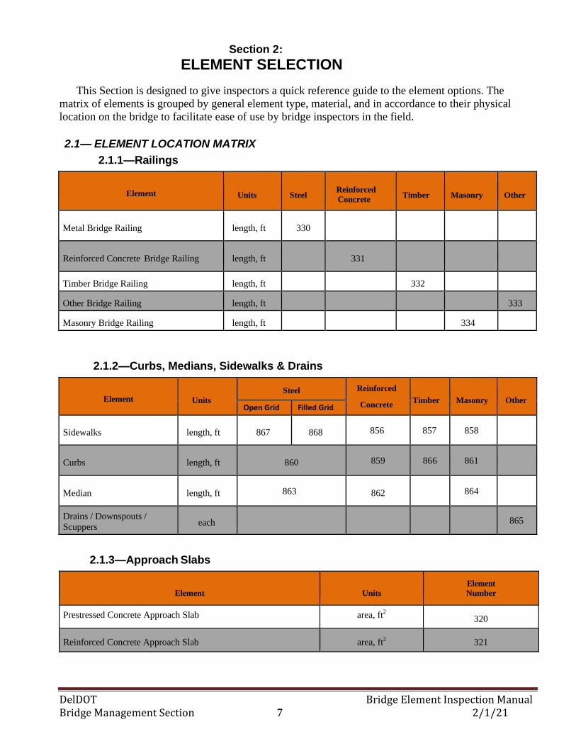
This Section is designed to give inspectors a quick reference guide to the element options. The
matrix of elements is grouped by general element type, material, and in accordance to their physical
location on the bridge to facilitate ease of use by bridge inspectors in the field.
2.1 — ELEMENT LOCATION MATRIX
2.1.1—Railings
2.1.2—Curbs, Medians, Sidewalks & Drains
2.1.3—Approach Slabs
Element
Units
Element
Number
Prestressed Concrete Approach Slab area, ft2 320
Reinforced Concrete Approach Slab area, ft2 321
Element Units
Steel
Reinforced
Concrete
Timber
Masonry
Other
Metal Bridge Railing length, ft 330
Reinforced Concrete Bridge Railing length, ft 331
Timber Bridge Railing length, ft 332
Other Bridge Railing length, ft 333
Masonry Bridge Railing length, ft 334
Element Units
Steel Reinforced
Concrete
Timber
Masonry
Other
Open Grid Filled Grid
Sidewalks length, ft 867 868 856 857 858
Curbs length, ft 860 859 866 861
Median length, ft 863 862 864
Drains / Downspouts /
Scuppers each 865
DelDOT Bridge Element Inspection Manual Bridge Management Section 8 2/1/21
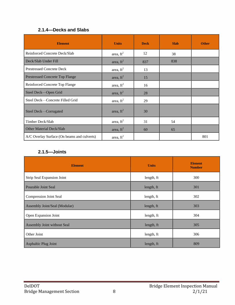
2.1.4—Decks and Slabs
Element
Units
Deck
Slab
Other
Reinforced Concrete Deck/Slab area, ft2 12 38
Deck/Slab Under Fill area, ft2 837 838
Prestressed Concrete Deck area, ft2 13
Prestressed Concrete Top Flange area, ft2 15
Reinforced Concrete Top Flange area, ft2 16
Steel Deck—Open Grid area, ft2 28
Steel Deck—Concrete Filled Grid area, ft2 29
Steel Deck—Corrugated area, ft2 30
Timber Deck/Slab area, ft2 31 54
Other Material Deck/Slab area, ft2 60 65
A/C Overlay Surface (On beams and culverts) area, ft2 801
2.1.5—Joints
Element
Units Element
Number
Strip Seal Expansion Joint length, ft 300
Pourable Joint Seal length, ft 301
Compression Joint Seal length, ft 302
Assembly Joint/Seal (Modular) length, ft 303
Open Expansion Joint length, ft 304
Assembly Joint without Seal length, ft 305
Other Joint length, ft 306
Asphaltic Plug Joint length, ft 809
DelDOT Bridge Element Inspection Manual Bridge Management Section 9 2/1/21
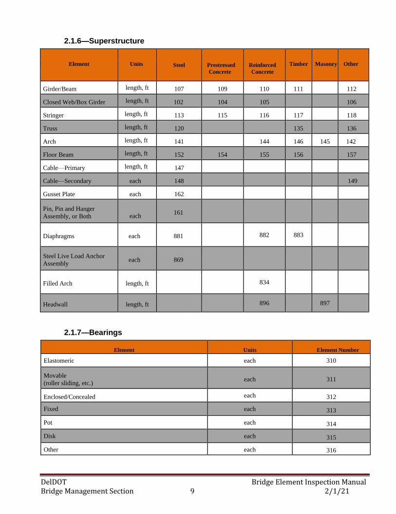
2.1.6—Superstructure
2.1.7—Bearings
Element
Units
Element Number
Elastomeric each 310
Movable
(roller sliding, etc.) each 311
Enclosed/Concealed each 312
Fixed each 313
Pot each 314
Disk each 315
Other each 316
Element
Units Steel
Prestressed
Concrete
Reinforced
Concrete
Timber
Masonry
Other
Girder/Beam length, ft 107 109 110 111 112
Closed Web/Box Girder length, ft 102 104 105 106
Stringer length, ft 113 115 116 117 118
Truss length, ft 120 135 136
Arch length, ft 141 144 146 145 142
Floor Beam length, ft 152 154 155 156 157
Cable—Primary length, ft 147
Cable—Secondary each 148 149
Gusset Plate each 162
Pin, Pin and Hanger
Assembly, or Both
each 161
Diaphragms each 881
882 883
Steel Live Load Anchor
Assembly each 869
Filled Arch length, ft
834
Headwall length, ft
896 897
DelDOT Bridge Element Inspection Manual Bridge Management Section 10 2/1/21
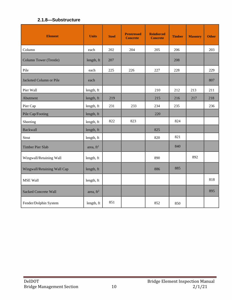
2.1.8—Substructure
Element
Units
Steel Prestressed
Concrete
Reinforced
Concrete
Timber
Masonry
Other
Column each 202 204 205 206 203
Column Tower (Trestle) length, ft 207 208
Pile each 225 226 227 228 229
Jacketed Column or Pile each 807
Pier Wall length, ft 210 212 213 211
Abutment length, ft 219 215 216 217 218
Pier Cap length, ft 231 233 234 235 236
Pile Cap/Footing length, ft 220
Sheeting length, ft 822 823 824
Backwall length, ft 825
Strut length, ft 820 821
Timber Pier Slab area, ft2 840
Wingwall/Retaining Wall length, ft 890 892
Wingwall/Retaining Wall Cap length, ft 886 885
MSE Wall length, ft 818
Sacked Concrete Wall area, ft2 895
Fender/Dolphin System length, ft 851 852 850
DelDOT Bridge Element Inspection Manual Bridge Management Section 11 2/1/21
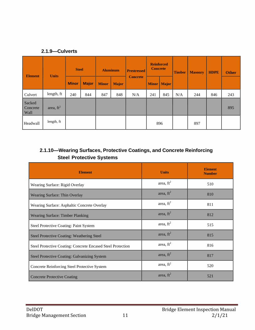
2.1.9—Culverts
Element
Units
Steel
Aluminum Prestressed
Concrete
Reinforced
Concrete
Timber
Masonry
HDPE
Other
Minor Major Minor Major Minor Major
Culvert length, ft 240 844 847 848 N/A 241 845 N/A 244 846 243
Sacked
Concrete
Wall
area, ft2
895
Headwall length, ft
896 897
2.1.10—Wearing Surfaces, Protective Coatings, and Concrete Reinforcing
Steel Protective Systems
Element
Units Element
Number
Wearing Surface: Rigid Overlay area, ft2 510
Wearing Surface: Thin Overlay area, ft2 810
Wearing Surface: Asphaltic Concrete Overlay area, ft2 811
Wearing Surface: Timber Planking area, ft2 812
Steel Protective Coating: Paint System area, ft2 515
Steel Protective Coating: Weathering Steel area, ft2 815
Steel Protective Coating: Concrete Encased Steel Protection area, ft2 816
Steel Protective Coating: Galvanizing System area, ft2 817
Concrete Reinforcing Steel Protective System area, ft2 520
Concrete Protective Coating area, ft2 521
DelDOT Bridge Element Inspection Manual Bridge Management Section 12 2/1/21
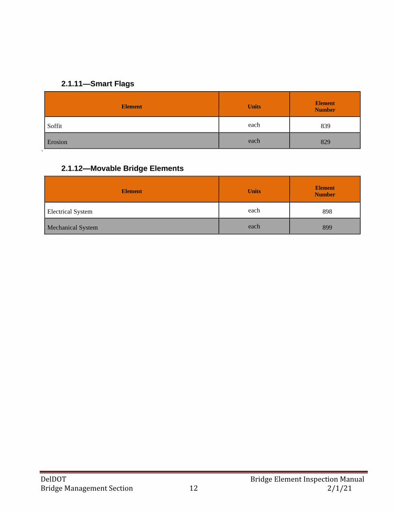
2.1.11—Smart Flags
Element
Units Element
Number
Soffit each 839
Erosion each 829
`
2.1.12—Movable Bridge Elements
Element
Units Element
Number
Electrical System each 898
Mechanical System each 899
DelDOT Bridge Element Inspection Manual Bridge Management Section 13 2/1/21
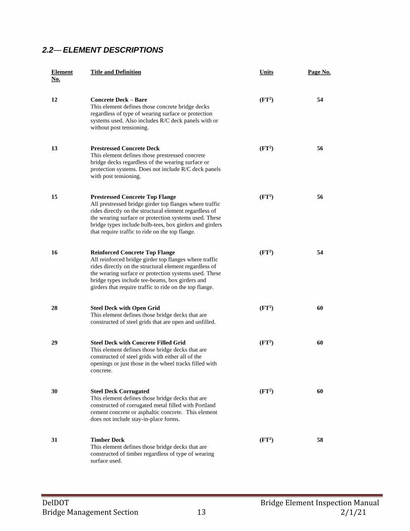
2.2— ELEMENT DESCRIPTIONS
Element Title and Definition Units Page No.
No.
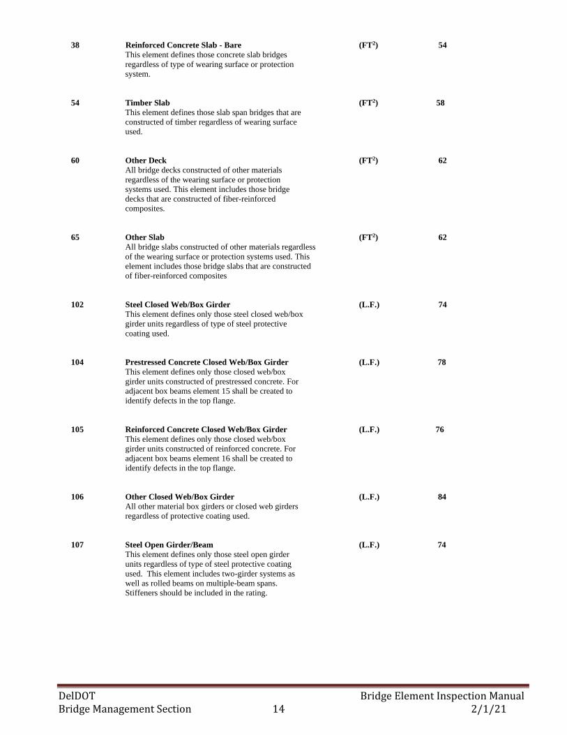
12 Concrete Deck – Bare (FT2) 54
This element defines those concrete bridge decks
regardless of type of wearing surface or protection
systems used. Also includes R/C deck panels with or
without post tensioning.
13 Prestressed Concrete Deck (FT2) 56
This element defines those prestressed concrete
bridge decks regardless of the wearing surface or
protection systems. Does not include R/C deck panels
with post tensioning.
15 Prestressed Concrete Top Flange (FT2) 56
All prestressed bridge girder top flanges where traffic
rides directly on the structural element regardless of
the wearing surface or protection systems used. These
bridge types include bulb-tees, box girders and girders
that require traffic to ride on the top flange.
16 Reinforced Concrete Top Flange (FT2) 54
All reinforced bridge girder top flanges where traffic
rides directly on the structural element regardless of
the wearing surface or protection systems used. These
bridge types include tee-beams, box girders and
girders that require traffic to ride on the top flange.
28 Steel Deck with Open Grid (FT2) 60
This element defines those bridge decks that are
constructed of steel grids that are open and unfilled.
29 Steel Deck with Concrete Filled Grid (FT2) 60
This element defines those bridge decks that are
constructed of steel grids with either all of the
openings or just those in the wheel tracks filled with
concrete.
30 Steel Deck Corrugated (FT2) 60
This element defines those bridge decks that are
constructed of corrugated metal filled with Portland
cement concrete or asphaltic concrete. This element
does not include stay-in-place forms.
31 Timber Deck (FT2) 58
This element defines those bridge decks that are
constructed of timber regardless of type of wearing
surface used.
DelDOT Bridge Element Inspection Manual Bridge Management Section 14 2/1/21
38 Reinforced Concrete Slab - Bare (FT2) 54
This element defines those concrete slab bridges
regardless of type of wearing surface or protection
system.
54 Timber Slab (FT2) 58
This element defines those slab span bridges that are
constructed of timber regardless of wearing surface
used.
60 Other Deck (FT2) 62
All bridge decks constructed of other materials
regardless of the wearing surface or protection
systems used. This element includes those bridge
decks that are constructed of fiber-reinforced
composites.
65 Other Slab (FT2) 62
All bridge slabs constructed of other materials regardless
of the wearing surface or protection systems used. This
element includes those bridge slabs that are constructed
of fiber-reinforced composites
102 Steel Closed Web/Box Girder (L.F.) 74
This element defines only those steel closed web/box
girder units regardless of type of steel protective
coating used.
104 Prestressed Concrete Closed Web/Box Girder (L.F.) 78
This element defines only those closed web/box
girder units constructed of prestressed concrete. For
adjacent box beams element 15 shall be created to
identify defects in the top flange.
105 Reinforced Concrete Closed Web/Box Girder (L.F.) 76
This element defines only those closed web/box
girder units constructed of reinforced concrete. For
adjacent box beams element 16 shall be created to
identify defects in the top flange.
106 Other Closed Web/Box Girder (L.F.) 84
All other material box girders or closed web girders
regardless of protective coating used.
107 Steel Open Girder/Beam (L.F.) 74
This element defines only those steel open girder
units regardless of type of steel protective coating
used. This element includes two-girder systems as
well as rolled beams on multiple-beam spans.
Stiffeners should be included in the rating.
DelDOT Bridge Element Inspection Manual Bridge Management Section 15 2/1/21
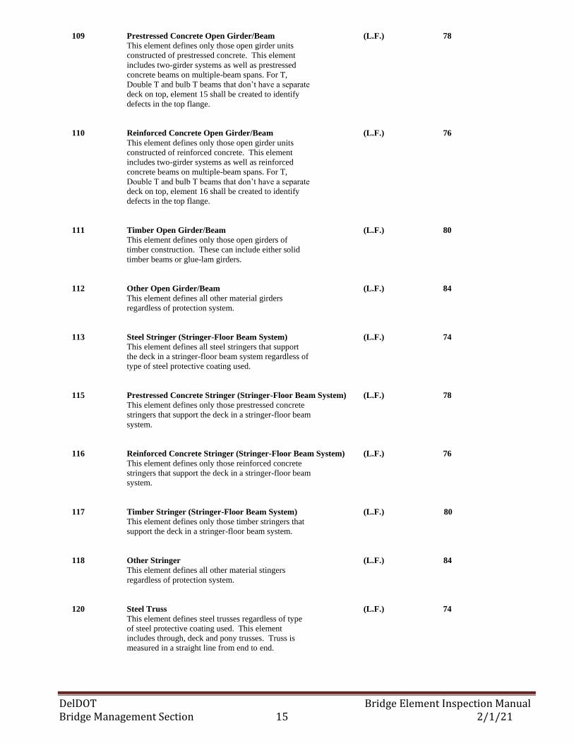
109 Prestressed Concrete Open Girder/Beam (L.F.) 78
This element defines only those open girder units
constructed of prestressed concrete. This element
includes two-girder systems as well as prestressed
concrete beams on multiple-beam spans. For T,
Double T and bulb T beams that don’t have a separate
deck on top, element 15 shall be created to identify
defects in the top flange.
110 Reinforced Concrete Open Girder/Beam (L.F.) 76
This element defines only those open girder units
constructed of reinforced concrete. This element
includes two-girder systems as well as reinforced
concrete beams on multiple-beam spans. For T,
Double T and bulb T beams that don’t have a separate
deck on top, element 16 shall be created to identify
defects in the top flange.
111 Timber Open Girder/Beam (L.F.) 80
This element defines only those open girders of
timber construction. These can include either solid
timber beams or glue-lam girders.
112 Other Open Girder/Beam (L.F.) 84
This element defines all other material girders
regardless of protection system.
113 Steel Stringer (Stringer-Floor Beam System) (L.F.) 74
This element defines all steel stringers that support
the deck in a stringer-floor beam system regardless of
type of steel protective coating used.
115 Prestressed Concrete Stringer (Stringer-Floor Beam System) (L.F.) 78
This element defines only those prestressed concrete
stringers that support the deck in a stringer-floor beam
system.
116 Reinforced Concrete Stringer (Stringer-Floor Beam System) (L.F.) 76
This element defines only those reinforced concrete
stringers that support the deck in a stringer-floor beam
system.
117 Timber Stringer (Stringer-Floor Beam System) (L.F.) 80
This element defines only those timber stringers that
support the deck in a stringer-floor beam system.
118 Other Stringer (L.F.) 84
This element defines all other material stingers
regardless of protection system.
120 Steel Truss (L.F.) 74
This element defines steel trusses regardless of type
of steel protective coating used. This element
includes through, deck and pony trusses. Truss is
measured in a straight line from end to end.
DelDOT Bridge Element Inspection Manual Bridge Management Section 16 2/1/21
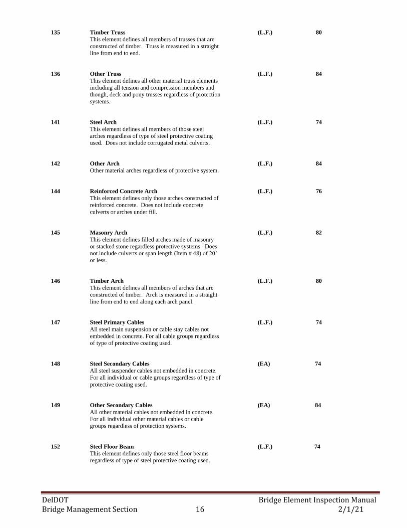
135 Timber Truss (L.F.) 80
This element defines all members of trusses that are
constructed of timber. Truss is measured in a straight
line from end to end.
136 Other Truss (L.F.) 84
This element defines all other material truss elements
including all tension and compression members and
though, deck and pony trusses regardless of protection
systems.
141 Steel Arch (L.F.) 74
This element defines all members of those steel
arches regardless of type of steel protective coating
used. Does not include corrugated metal culverts.
142 Other Arch (L.F.) 84
Other material arches regardless of protective system.
144 Reinforced Concrete Arch (L.F.) 76
This element defines only those arches constructed of
reinforced concrete. Does not include concrete
culverts or arches under fill.
145 Masonry Arch (L.F.) 82
This element defines filled arches made of masonry
or stacked stone regardless protective systems. Does
not include culverts or span length (Item # 48) of 20’
or less.
146 Timber Arch (L.F.) 80
This element defines all members of arches that are
constructed of timber. Arch is measured in a straight
line from end to end along each arch panel.
147 Steel Primary Cables (L.F.) 74
All steel main suspension or cable stay cables not
embedded in concrete. For all cable groups regardless
of type of protective coating used.
148 Steel Secondary Cables (EA) 74
All steel suspender cables not embedded in concrete.
For all individual or cable groups regardless of type of
protective coating used.
149 Other Secondary Cables (EA) 84
All other material cables not embedded in concrete.
For all individual other material cables or cable
groups regardless of protection systems.
152 Steel Floor Beam (L.F.) 74
This element defines only those steel floor beams
regardless of type of steel protective coating used.
DelDOT Bridge Element Inspection Manual Bridge Management Section 17 2/1/21
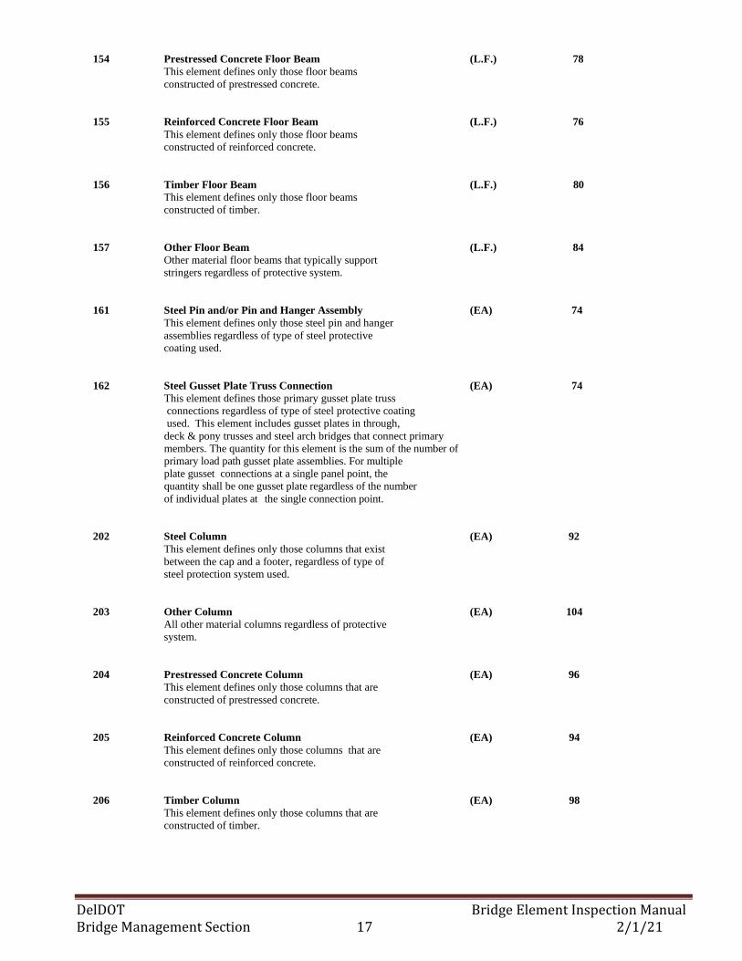
154 Prestressed Concrete Floor Beam (L.F.) 78
This element defines only those floor beams
constructed of prestressed concrete.
155 Reinforced Concrete Floor Beam (L.F.) 76
This element defines only those floor beams
constructed of reinforced concrete.
156 Timber Floor Beam (L.F.) 80
This element defines only those floor beams
constructed of timber.
157 Other Floor Beam (L.F.) 84
Other material floor beams that typically support
stringers regardless of protective system.
161 Steel Pin and/or Pin and Hanger Assembly (EA) 74
This element defines only those steel pin and hanger
assemblies regardless of type of steel protective
coating used.
162 Steel Gusset Plate Truss Connection (EA) 74
This element defines those primary gusset plate truss
connections regardless of type of steel protective coating
used. This element includes gusset plates in through,
deck & pony trusses and steel arch bridges that connect primary
members. The quantity for this element is the sum of the number of
primary load path gusset plate assemblies. For multiple
plate gusset connections at a single panel point, the
quantity shall be one gusset plate regardless of the number
of individual plates at the single connection point.
202 Steel Column (EA) 92
This element defines only those columns that exist
between the cap and a footer, regardless of type of
steel protection system used.
203 Other Column (EA) 104
All other material columns regardless of protective
system.
204 Prestressed Concrete Column (EA) 96
This element defines only those columns that are
constructed of prestressed concrete.
205 Reinforced Concrete Column (EA) 94
This element defines only those columns that are
constructed of reinforced concrete.
206 Timber Column (EA) 98
This element defines only those columns that are
constructed of timber.
DelDOT Bridge Element Inspection Manual Bridge Management Section 18 2/1/21
207 Steel Column Tower (Trestle) (L.F.) 92
Steel built-up or frame tower supports regardless of
type of steel protective coating used. Includes
movable bridge machinery supports.
208 Timber Column Tower (Trestle) (L.F.) 98
Framed timber supports for timber trestle/towers
regardless of protective system.
210 Reinforced Concrete Pier Wall (L.F.) 94
This element defines only those pier walls (shafts)
constructed of reinforced concrete.
211 Other Pier Wall (L.F.) 104
This element defines only those pier walls constructed
of other materials.
212 Timber Pier Wall (L.F.) 98
Those timber pier wall systems that include the pile,
timber sheeting material and fill material. Does not
include the timber pier cap or a timber bent systems.
213 Masonry Pier Wall (L.F.) 100
Those pier walls constructed of block or stone placed
with or without mortar regardless of protective
systems.
215 Reinforced Concrete Abutment (L.F.) 94
This element defines only those abutments
constructed of reinforced concrete. Deficiencies in
the header are noted in the appropriate joint element.
216 Timber Abutment (L.F.) 98
This element defines only those abutment caps
constructed of timber.
217 Masonry Abutment (L.F.) 100
This element defines only those abutments
constructed of masonry.
218 Other Abutment (L.F.) 104
Other material abutment systems, including the sheet
material retaining the embankment, and integral
wingwalls and abutment extensions. For all abutments
regardless of protection systems.
219 Steel Abutment (L.F.) 92
Steel abutments, including the sheet material retaining
the embankment and monolithic wingwalls and
abutment extensions. For all abutments regardless of
type of protective coating used. Does not include steel
sheeting used as wingwalls.
DelDOT Bridge Element Inspection Manual Bridge Management Section 19 2/1/21
220 Reinforced Concrete Pile Cap/Footing (L.F.) 94
Reinforced pile caps/ footings that are visible for
inspections, including submerged pile caps/footings
that are visible during an underwater inspection. The
exposure may be intentional or caused by erosion or
scour. This element also includes those reinforced
concrete abutment or pile caps/footings belonging to a
corrugated metal pipe arch that are submerged and are
visible for inspection. This shouldn’t be used for
frame culverts.
225 Steel Pile (EA) 92
This element defines only those piles, including
monotubes or steel pipe regardless of type of steel
protective coating used. Piles may be submerged or
un-submerged
226 Prestressed Concrete Piles (EA) 96
This element defines only those piles that are
constructed of prestressed concrete. Piles may be
submerged or un-submerged.
227 Reinforced Concrete Piles (EA) 94
This element defines only those piles that are
constructed of reinforced concrete. Piles may be
submerged or un-submerged.
228 Timber Piles (EA) 98
This element defines only those piles that are
constructed of timber. Piles may be submerged or un-
submerged.
229 Other Pile (EA) 104
All other material piles regardless of protective
system. Piles may be submerged or un-submerged
231 Steel Pier Cap (L.F.) 92
This element defines only those steel pier caps
regardless of type of steel protective coating used.
233 Prestressed Concrete Pier Cap (L.F.) 96
This element defines only those pier caps that are
constructed of prestressed concrete.
234 Reinforced Concrete Pier Cap (L.F.) 94
This element defines only those pier caps that are
constructed of reinforced concrete.
235 Timber Pier Cap (L.F.) 98
This element defines only those pier caps that are
constructed of timber.
DelDOT Bridge Element Inspection Manual Bridge Management Section 20 2/1/21
236 Other Pier Cap (L.F.) 104
Other material pier caps that support girders that
transfer load into piles or columns. For all other
material pier caps regardless of protective system.
240 Steel Culvert (L.F.) 106
This element defines all steel culverts that have a span
length of less than seven feet (7’).
241 Concrete Culvert (L.F.) 110
This element defines all precast and cast-in-place
pipes.
243 Other Culvert (L.F.) 114
Other material/type culverts including arches, round or
elliptical pipes. These culverts do not include metal,
concrete, masonry or timber material types.
244 Masonry Culvert (L.F.) 112
This element defines all culverts constructed of
masonry.
300 Strip Seal Expansion Joint (L.F.) 66
This element defines only those expansion joint
devices that utilize a neoprene-type waterproof gland
with steel extrusion to anchor the gland.
301 Pourable Joint Seal (L.F.) 70
This element defines only those joints filled with a
pourable seal. This element includes sections of the
joint between the deck and backwall, approach slab
and backwall and parapet and approach slab.
302 Compression Joint Seal (L.F.) 66
This element defines only those joints filled with a
performed compression-type seal.
303 Assembly Joint Seal (modular) (L.F.) 66
This element defines only those joints filled with an
assembly mechanism, which does have a seal.
304 Open Expansion Joint (L.F.) 68
This element defines only those joints that are open
and not sealed.
305 Assembly Joint w/o Seal (modular) (L.F.) 68
Only assembly joints that are open and not sealed,
including finger and sliding plate joints.
306 Other Joint (L.F.) 72
Only those other joints that are not defined by any
other joint element.
DelDOT Bridge Element Inspection Manual Bridge Management Section 21 2/1/21
310 Elastomeric Bearing (EA) 86
This element defines only those bridges bearings that
are constructed primarily of elastomers with fabric or
metal reinforcement
311 Movable Bearing (roller, sliding, etc.) (EA) 88
This element defines only those bridge bearings that
provide for both deflection and longitudinal
movement by means of roller, rocker or sliding
mechanisms.
312 Enclosed/Concealed Bearing (EA) 88
This element defines only those bridge bearings that
are enclosed so that they are not open for detailed
inspection.
313 Fixed Bearing (EA) 88
This element defines only those bridge bearings that
provide for deflection only.
314 Pot Bearing (EA) 86
This element defines those high-load bearings with
confined elastomer. The bearing may be fixed against
horizontal movement, guided to allow movement in
one direction, or floating to allow sliding in any
direction.
315 Disk Bearing (EA) 88
This element defines those high-load bearings with a
hard plastic disk. The bearing may be fixed against
horizontal movement, guided to allow movement in
one direction, or floating to allow sliding in any
direction.
316 Other Bearing (EA) 90
All other material bridge bearings regardless of
translation or rotation constraints.
320 Prestressed Concrete Approach Slab (FT2) 52
This element defines those structural sections between
the abutment and the approach pavement that are
constructed of prestressed concrete. . Slabs with an
AC overlay, element 811 shall be used to document
the AC overlay condition.
321 Reinforced Concrete Approach Slab (FT2) 50
This element defines those structural sections between
the abutment and approach pavement that are
constructed of reinforced concrete. Slabs with an AC
overlay, element 811 shall be used to document the
AC overlay condition.
DelDOT Bridge Element Inspection Manual Bridge Management Section 22 2/1/21
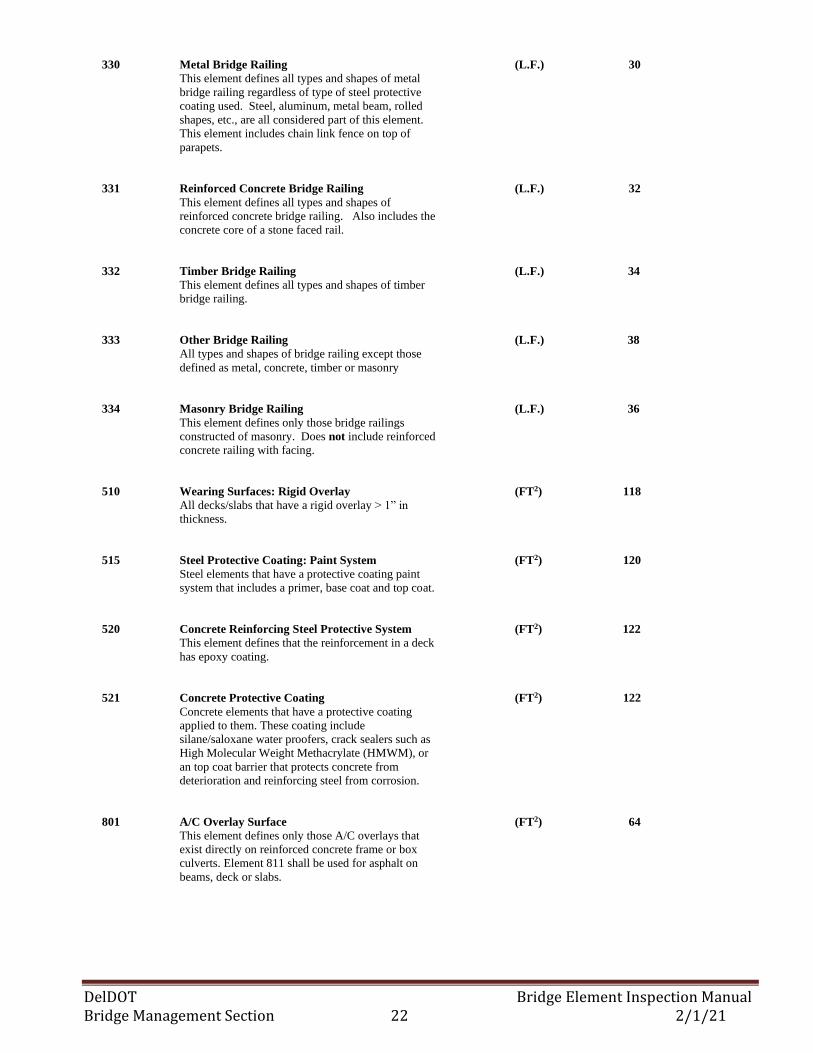
330 Metal Bridge Railing (L.F.) 30
This element defines all types and shapes of metal
bridge railing regardless of type of steel protective
coating used. Steel, aluminum, metal beam, rolled
shapes, etc., are all considered part of this element.
This element includes chain link fence on top of
parapets.
331 Reinforced Concrete Bridge Railing (L.F.) 32
This element defines all types and shapes of
reinforced concrete bridge railing. Also includes the
concrete core of a stone faced rail.
332 Timber Bridge Railing (L.F.) 34
This element defines all types and shapes of timber
bridge railing.
333 Other Bridge Railing (L.F.) 38
All types and shapes of bridge railing except those
defined as metal, concrete, timber or masonry
334 Masonry Bridge Railing (L.F.) 36
This element defines only those bridge railings
constructed of masonry. Does not include reinforced
concrete railing with facing.
510 Wearing Surfaces: Rigid Overlay (FT2) 118
All decks/slabs that have a rigid overlay > 1” in
thickness.
515 Steel Protective Coating: Paint System (FT2) 120
Steel elements that have a protective coating paint
system that includes a primer, base coat and top coat.
520 Concrete Reinforcing Steel Protective System (FT2) 122
This element defines that the reinforcement in a deck
has epoxy coating.
521 Concrete Protective Coating (FT2) 122
Concrete elements that have a protective coating
applied to them. These coating include
silane/saloxane water proofers, crack sealers such as
High Molecular Weight Methacrylate (HMWM), or
an top coat barrier that protects concrete from
deterioration and reinforcing steel from corrosion.
801 A/C Overlay Surface (FT2) 64
This element defines only those A/C overlays that
exist directly on reinforced concrete frame or box
culverts. Element 811 shall be used for asphalt on
beams, deck or slabs.
DelDOT Bridge Element Inspection Manual Bridge Management Section 23 2/1/21
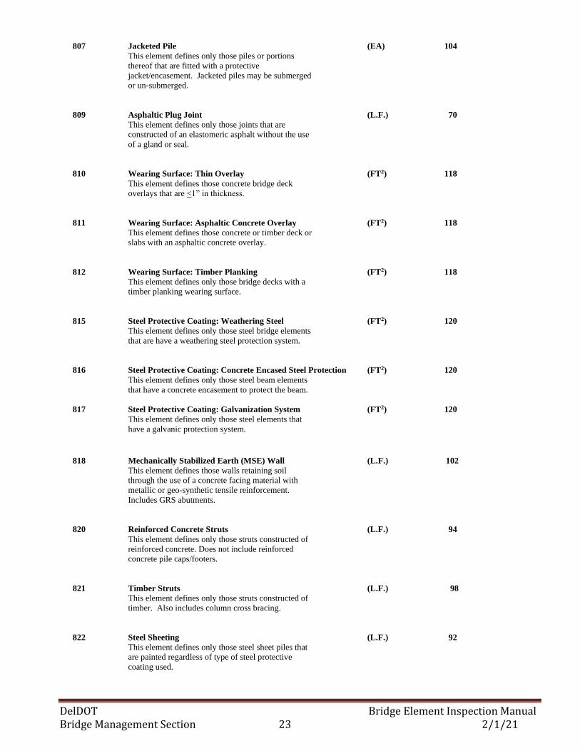
807 Jacketed Pile (EA) 104
This element defines only those piles or portions
thereof that are fitted with a protective
jacket/encasement. Jacketed piles may be submerged
or un-submerged.
809 Asphaltic Plug Joint (L.F.) 70
This element defines only those joints that are
constructed of an elastomeric asphalt without the use
of a gland or seal.
810 Wearing Surface: Thin Overlay (FT2) 118
This element defines those concrete bridge deck
overlays that are <1” in thickness.
811 Wearing Surface: Asphaltic Concrete Overlay (FT2) 118
This element defines those concrete or timber deck or
slabs with an asphaltic concrete overlay.
812 Wearing Surface: Timber Planking (FT2) 118
This element defines only those bridge decks with a
timber planking wearing surface.
815 Steel Protective Coating: Weathering Steel (FT2) 120
This element defines only those steel bridge elements
that are have a weathering steel protection system.
816 Steel Protective Coating: Concrete Encased Steel Protection (FT2) 120
This element defines only those steel beam elements
that have a concrete encasement to protect the beam.
817 Steel Protective Coating: Galvanization System (FT2) 120
This element defines only those steel elements that
have a galvanic protection system.
818 Mechanically Stabilized Earth (MSE) Wall (L.F.) 102
This element defines those walls retaining soil
through the use of a concrete facing material with
metallic or geo-synthetic tensile reinforcement.
Includes GRS abutments.
820 Reinforced Concrete Struts (L.F.) 94
This element defines only those struts constructed of
reinforced concrete. Does not include reinforced
concrete pile caps/footers.
821 Timber Struts (L.F.) 98
This element defines only those struts constructed of
timber. Also includes column cross bracing.
822 Steel Sheeting (L.F.) 92
This element defines only those steel sheet piles that
are painted regardless of type of steel protective
coating used.
DelDOT Bridge Element Inspection Manual Bridge Management Section 24 2/1/21
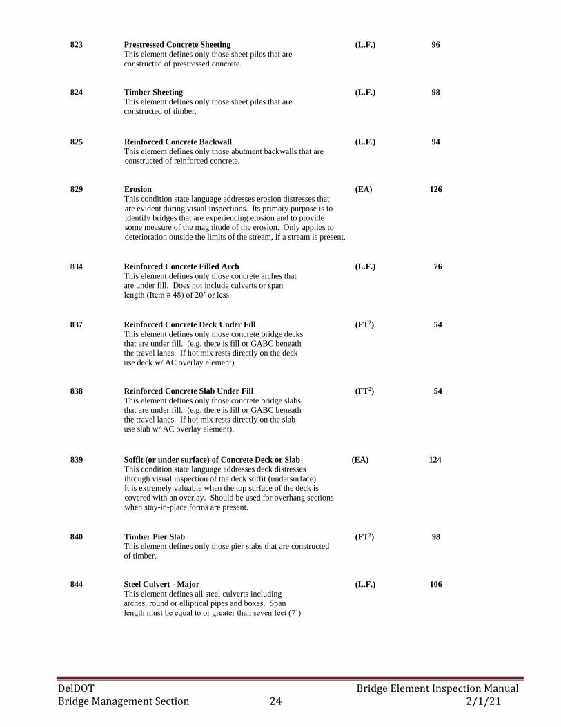
823 Prestressed Concrete Sheeting (L.F.) 96
This element defines only those sheet piles that are
constructed of prestressed concrete.
824 Timber Sheeting (L.F.) 98
This element defines only those sheet piles that are
constructed of timber.
825 Reinforced Concrete Backwall (L.F.) 94
This element defines only those abutment backwalls that are
constructed of reinforced concrete.
829 Erosion (EA) 126
This condition state language addresses erosion distresses that
are evident during visual inspections. Its primary purpose is to
identify bridges that are experiencing erosion and to provide
some measure of the magnitude of the erosion. Only applies to
deterioration outside the limits of the stream, if a stream is present.
834 Reinforced Concrete Filled Arch (L.F.) 76
This element defines only those concrete arches that
are under fill. Does not include culverts or span
length (Item # 48) of 20’ or less.
837 Reinforced Concrete Deck Under Fill (FT2) 54
This element defines only those concrete bridge decks
that are under fill. (e.g. there is fill or GABC beneath
the travel lanes. If hot mix rests directly on the deck
use deck w/ AC overlay element).
838 Reinforced Concrete Slab Under Fill (FT2) 54
This element defines only those concrete bridge slabs
that are under fill. (e.g. there is fill or GABC beneath
the travel lanes. If hot mix rests directly on the slab
use slab w/ AC overlay element).
839 Soffit (or under surface) of Concrete Deck or Slab (EA) 124
This condition state language addresses deck distresses
through visual inspection of the deck soffit (undersurface).
It is extremely valuable when the top surface of the deck is
covered with an overlay. Should be used for overhang sections
when stay-in-place forms are present.
840 Timber Pier Slab (FT2) 98
This element defines only those pier slabs that are constructed
of timber.
844 Steel Culvert - Major (L.F.) 106
This element defines all steel culverts including
arches, round or elliptical pipes and boxes. Span
length must be equal to or greater than seven feet (7’).
DelDOT Bridge Element Inspection Manual Bridge Management Section 25 2/1/21
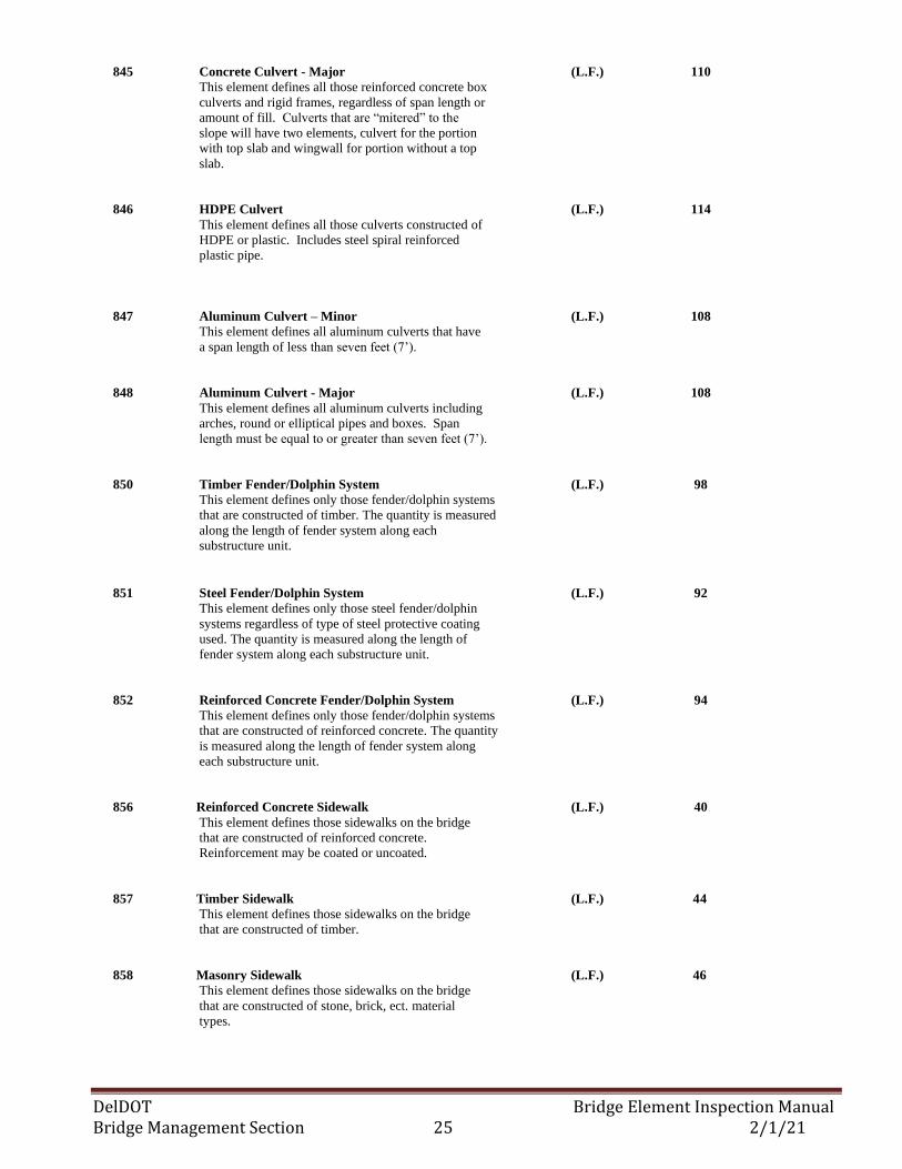
845 Concrete Culvert - Major (L.F.) 110
This element defines all those reinforced concrete box
culverts and rigid frames, regardless of span length or
amount of fill. Culverts that are “mitered” to the
slope will have two elements, culvert for the portion
with top slab and wingwall for portion without a top
slab.
846 HDPE Culvert (L.F.) 114
This element defines all those culverts constructed of
HDPE or plastic. Includes steel spiral reinforced
plastic pipe.
847 Aluminum Culvert – Minor (L.F.) 108
This element defines all aluminum culverts that have
a span length of less than seven feet (7’).
848 Aluminum Culvert - Major (L.F.) 108
This element defines all aluminum culverts including
arches, round or elliptical pipes and boxes. Span
length must be equal to or greater than seven feet (7’).
850 Timber Fender/Dolphin System (L.F.) 98
This element defines only those fender/dolphin systems
that are constructed of timber. The quantity is measured
along the length of fender system along each
substructure unit.
851 Steel Fender/Dolphin System (L.F.) 92
This element defines only those steel fender/dolphin
systems regardless of type of steel protective coating
used. The quantity is measured along the length of
fender system along each substructure unit.
852 Reinforced Concrete Fender/Dolphin System (L.F.) 94
This element defines only those fender/dolphin systems
that are constructed of reinforced concrete. The quantity
is measured along the length of fender system along
each substructure unit.
856 Reinforced Concrete Sidewalk (L.F.) 40
This element defines those sidewalks on the bridge
that are constructed of reinforced concrete.
Reinforcement may be coated or uncoated.
857 Timber Sidewalk (L.F.) 44
This element defines those sidewalks on the bridge
that are constructed of timber.
858 Masonry Sidewalk (L.F.) 46
This element defines those sidewalks on the bridge
that are constructed of stone, brick, ect. material
types.
DelDOT Bridge Element Inspection Manual Bridge Management Section 26 2/1/21
859 Reinforced Concrete Curb (L.F.) 40
This element defines those curbs on the bridge with a
defined joint between the sidewalk and the curb that
are constructed of reinforced concrete.
Reinforcement may be coated or uncoated.
860 Steel Curb (L.F.) 42
This element defines those curbs on the bridge
regardless of type of steel protective coating used.
861 Masonry Curb (L.F.) 46
This element defines those curbs on the bridge that are
constructed of masonry material types (i.e. stone, etc.).
862 Reinforced Concrete Median (L.F.) 40
This element defines those medians on the bridge that
are constructed of reinforced concrete.
Reinforcement may be coated or uncoated.
863 Steel Median (L.F.) 42
This element defines those medians on the bridge that
are constructed of steel regardless of type of steel
protective coating used.
864 Masonry Median (L.F.) 46
This element defines those medians on the bridge that
are constructed of masonry material types (i.e. stone,
brick, etc.).
865 Drains/Downspouts/Scuppers (EA) 48
This element defines those drains, downspouts and
scuppers on the bridge that are constructed of any
material type (painted or unpainted steel, cast iron,
formed concrete, plastic, etc.).
866 Timber Curb (L.F.) 44
This element defines those curbs on the bridge that
are constructed of timber.
867 Steel Sidewalk – Open Grid (L.F.) 42
This element defines those sidewalks that are
constructed of steel grids that are open and unfilled.
868 Steel Sidewalk - Filled Grid (L.F.) 42
This element defines those sidewalks that are
constructed of steel grids with all the openings filled
with concrete, including orthotropic sidewalks.
869 Steel Live Load Anchor Assembly (EA) 74
This element defines only those movable bridge steel
live load anchor assemblies regardless of type of steel
protective coating used.
DelDOT Bridge Element Inspection Manual Bridge Management Section 27 2/1/21
881 Steel Diaphragm (EA) 74
This element defines only those steel diaphragms
regardless of type of steel protective coating used.
882 Reinforced Concrete Diaphragm (EA) 76
This element defines only those diaphragms that are
constructed of reinforced concrete. Does not include
haunches at the ends of concrete decks.
883 Timber Diaphragm (EA) 80
This element defines only those diaphragms or cross
bracing units that are constructed of timber.
885 Timber Wingwall / Retaining Wall Cap (L.F.) 98
This element defines those wingwall caps constructed of
timber.
886 Reinforced Concrete Wingwall / Retaining Wall Cap (L.F.) 94
This element defines those MSE wall or wingwall /
retaining wall caps constructed of reinforced concrete
that are not monolithic with the wall. Applicable to
walls constructed of any material.
890 Reinforced Concrete Wingwall / Retaining Wall (L.F.) 94
This element defines only those wingwall or retaining
wall units constructed of reinforced concrete.
892 Masonry Wingwall / Retaining Wall (L.F.) 100
This element defines only those wingwalls or
retaining walls constructed of masonry or a
combination of materials.
895 Sacked Concrete Wall (FT2) 116
This element defines walls constructed of sacked
concrete riprap. This element only applies to
headwalls, wingwalls, and retaining walls constructed
of sacked concrete riprap. Walls may have a slight
batter.
896 Reinforced Concrete Headwall (L.F.) 94
This element defines only those headwall units
constructed of reinforced concrete and retaining fill.
897 Masonry Headwall (L.F.) 112
This element defines only those headwall units
constructed of masonry and retains fill.
898 Movable Bridge Electrical System (EA) 128
This element defines the entire electrical system for a
movable bridge structure.
899 Movable Bridge Mechanical System (EA) 130
This element defines the entire mechanical system for
a movable bridge structure.
DelDOT Bridge Element Inspection Manual Bridge Management Section 28 2/1/21
DelDOT Bridge Element Inspection Manual Bridge Management Section 29 2/1/21
Section 3:
DETAILED ELEMENT CONDITION STATE DESCRIPTIONS
This Section describes the elements’ detailed use in inspection and bridge management. Each
detailed element description is broken down into three subsections:
1. Description—Detailed identification and classification of the element, including units of
measurement, and guidelines on how to collect the quantity of the element in a consistent
manner.
2. Element Commentary—Additional considerations for the inspector to be aware of during data
collection. (Not all elements will have an Element Commentary)
3. Condition State Definitions—Defect descriptions and severity, with guidelines to
the inspector for determining defect severity.
All the elements described in this Section include the standard set of National Bridge Elements
(NBE’s), Bridge Management Elements (BME’s) and Agency developed Elements (ADE’s). The
elements are organized by major groupings such as Decks and Slabs, Superstructure, Substructure,
Joints, and Bearings. The common defects identified for each element material are further detailed in
Appendix E.
DelDOT Bridge Element Inspection Manual Bridge Management Section 30 2/1/21
3.1— BRIDGE RAIL ELEMENTS
3.1.1 – Metal Bridge Railing
Description: All types and shapes of metal bridge railing. Steel, aluminum, metal beam, rolled shapes,
ect. will all be considered part of this element. The correct steel protective coating element shall be used.
Element Title and Definition Units
330 Metal Bridge Railing (L.F.)
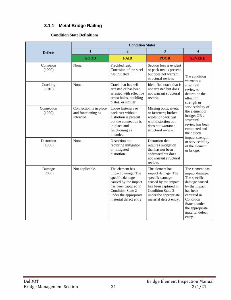
DelDOT Bridge Element Inspection Manual Bridge Management Section 31 2/1/21
3.1.1—Metal Bridge Railing
Condition State Definitions
Defects
Condition States
1 2 3 4
GOOD FAIR POOR SEVERE
Corrosion
(1000)
None. Freckled rust.
Corrosion of the steel
has initiated.
Section loss is evident
or pack rust is present
but does not warrant
structural review.
The condition
warrants a
structural
review to
determine the
effect on
strength or
serviceability of
the element or
bridge; OR a
structural
review has been
completed and
the defects
impact strength
or serviceability
of the element
or bridge.
Cracking
(1010)
None. Crack that has self-
arrested or has been
arrested with effective
arrest holes, doubling
plates, or similar.
Identified crack that is
not arrested but does
not warrant structural
review.
Connection
(1020)
Connection is in place
and functioning as
intended.
Loose fasteners or
pack rust without
distortion is present
but the connection is
in place and
functioning as
intended.
Missing bolts, rivets,
or fasteners; broken
welds; or pack rust
with distortion but
does not warrant a
structural review.
Distortion
(1900)
None. Distortion not
requiring mitigation
or mitigated
distortion.
Distortion that
requires mitigation
that has not been
addressed but does
not warrant structural
review.
Damage
(7000)
Not applicable. The element has
impact damage. The
specific damage
caused by the impact
has been captured in
Condition State 2
under the appropriate
material defect entry.
The element has
impact damage. The
specific damage
caused by the impact
has been captured in
Condition State 3
under the appropriate
material defect entry.
The element has
impact damage.
The specific
damage caused
by the impact
has been
captured in
Condition
State 4 under
the appropriate
material defect
entry.
DelDOT Bridge Element Inspection Manual Bridge Management Section 32 2/1/21
3.1—BRIDGE RAIL ELEMENTS
3.1.2 – Reinforced Concrete Bridge Railing
Description: All types and shapes of reinforced concrete bridge railing. This element includes
reinforced concrete bridge railings with stone facing.
Element 521 (Concrete Protective Coating) shall be used for each individual element type that has a
protective coating applied to them. These coatings include silane/siloxane water proofers, crack
sealers such as High Molecular Weight Methacrylate (HMWM), or any top coat barrier that protects
concrete from deterioration and reinforcing steel from corrosion. Element 520 (Concrete Reinforcing
Steel Protective System) shall be used for each individual element type that has a corrosion
protection system installed. Protection systems may include cathodic protection or addition of
anodes to mitigate corrosion.
Element Title and Definition Units
331 Reinforced Concrete Bridge Railing (L.F.)
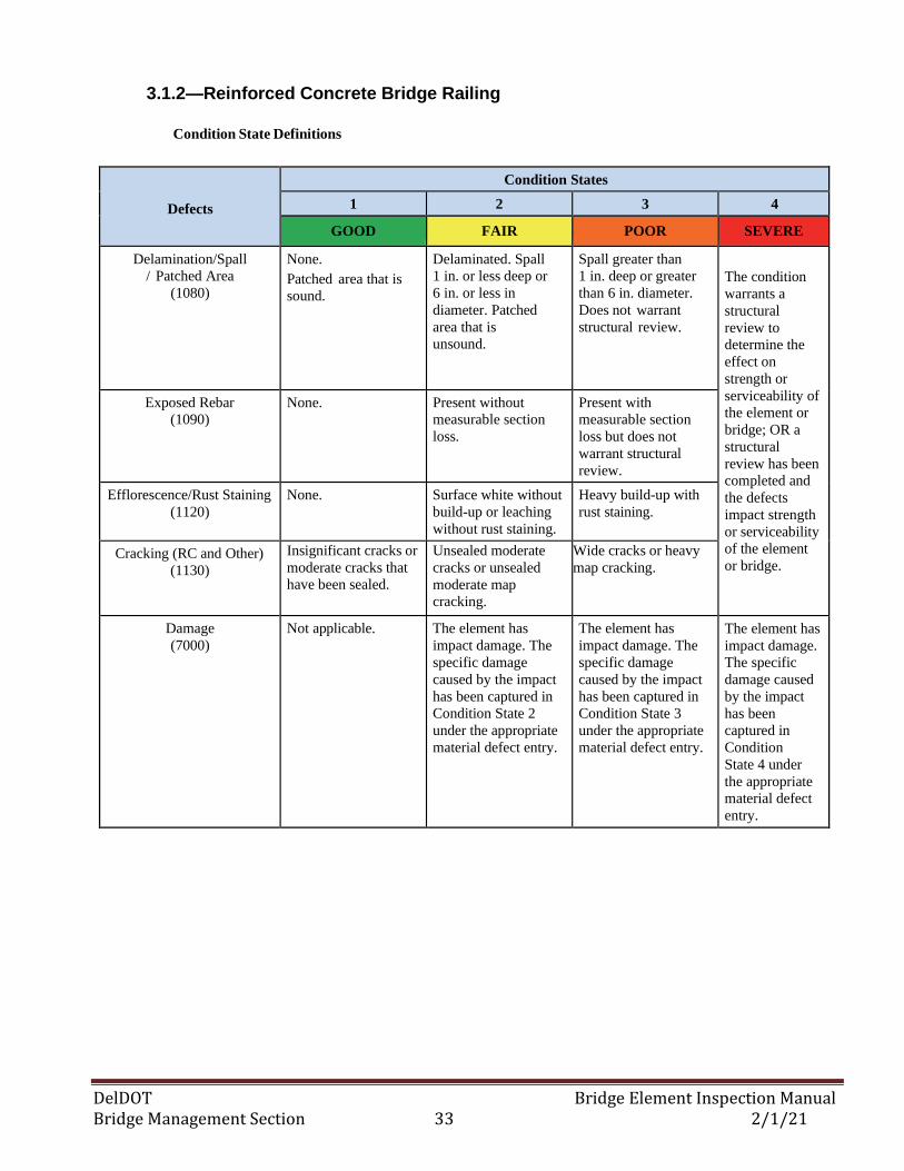
DelDOT Bridge Element Inspection Manual Bridge Management Section 33 2/1/21
3.1.2—Reinforced Concrete Bridge Railing
Condition State Definitions
Defects
Condition States
1 2 3 4
GOOD FAIR POOR SEVERE
Delamination/Spall
/ Patched Area
(1080)
None.
Patched area that is
sound.
Delaminated. Spall
1 in. or less deep or
6 in. or less in
diameter. Patched
area that is
unsound.
Spall greater than
1 in. deep or greater
than 6 in. diameter.
Does not warrant
structural review.
The condition
warrants a
structural
review to
determine the
effect on
strength or
serviceability of
the element or
bridge; OR a
structural
review has been
completed and
the defects
impact strength
or serviceability
of the element
or bridge.
Exposed Rebar
(1090)
None. Present without
measurable section
loss.
Present with
measurable section
loss but does not
warrant structural
review.
Efflorescence/Rust Staining
(1120)
None. Surface white without
build-up or leaching
without rust staining.
Heavy build-up with
rust staining.
Cracking (RC and Other)
(1130)
Insignificant cracks or
moderate cracks that
have been sealed.
Unsealed moderate
cracks or unsealed
moderate map
cracking.
Wide cracks or heavy
map cracking.
Damage
(7000)
Not applicable. The element has
impact damage. The
specific damage
caused by the impact
has been captured in
Condition State 2
under the appropriate
material defect entry.
The element has
impact damage. The
specific damage
caused by the impact
has been captured in
Condition State 3
under the appropriate
material defect entry.
The element has
impact damage.
The specific
damage caused
by the impact
has been
captured in
Condition
State 4 under
the appropriate
material defect
entry.
DelDOT Bridge Element Inspection Manual Bridge Management Section 34 2/1/21
3.1— BRIDGE RAIL ELEMENTS
3.1.3 – Timber Bridge Railing
Description: All timber bridge railings. This includes timber posts used for metal rails.
Element Title and Definition Units
332 Timber Bridge Railing (FT2)
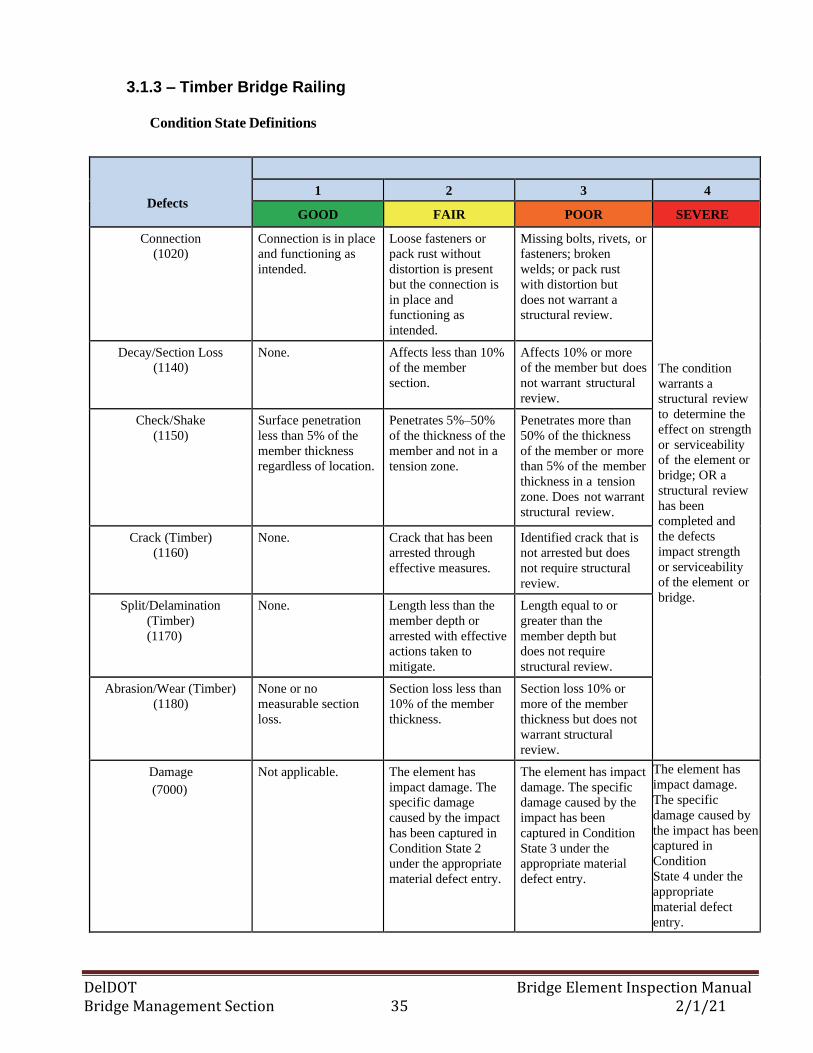
DelDOT Bridge Element Inspection Manual Bridge Management Section 35 2/1/21
3.1.3 – Timber Bridge Railing
Condition State Definitions
Defects
1 2 3 4
GOOD FAIR POOR SEVERE
Connection
(1020)
Connection is in place
and functioning as
intended.
Loose fasteners or
pack rust without
distortion is present
but the connection is
in place and
functioning as
intended.
Missing bolts, rivets, or
fasteners; broken
welds; or pack rust
with distortion but
does not warrant a
structural review.
The condition
warrants a
structural review
to determine the
effect on strength
or serviceability
of the element or
bridge; OR a
structural review
has been
completed and
the defects
impact strength
or serviceability
of the element or
bridge.
Decay/Section Loss
(1140)
None. Affects less than 10%
of the member
section.
Affects 10% or more
of the member but does
not warrant structural
review.
Check/Shake
(1150)
Surface penetration
less than 5% of the
member thickness
regardless of location.
Penetrates 5%–50%
of the thickness of the
member and not in a
tension zone.
Penetrates more than
50% of the thickness
of the member or more
than 5% of the member
thickness in a tension
zone. Does not warrant
structural review.
Crack (Timber)
(1160)
None. Crack that has been
arrested through
effective measures.
Identified crack that is
not arrested but does
not require structural
review.
Split/Delamination
(Timber)
(1170)
None. Length less than the
member depth or
arrested with effective
actions taken to
mitigate.
Length equal to or
greater than the
member depth but
does not require
structural review.
Abrasion/Wear (Timber)
(1180)
None or no
measurable section
loss.
Section loss less than
10% of the member
thickness.
Section loss 10% or
more of the member
thickness but does not
warrant structural
review.
Damage
(7000)
Not applicable. The element has
impact damage. The
specific damage
caused by the impact
has been captured in
Condition State 2
under the appropriate
material defect entry.
The element has impact
damage. The specific
damage caused by the
impact has been
captured in Condition
State 3 under the
appropriate material
defect entry.
The element has
impact damage.
The specific
damage caused by
the impact has been
captured in
Condition
State 4 under the
appropriate
material defect
entry.
DelDOT Bridge Element Inspection Manual Bridge Management Section 36 2/1/21
3.1— BRIDGE RAIL ELEMENTS
3.1.4 – Masonry Bridge Railing
Description: All types and shapes of masonry block or stone bridge railing. All elements of the railing
must be masonry block or stone. This element does not include reinforced concrete bridge railing with
stone facing.
Element Title and Definition Units
334 Masonry Bridge Railing (L.F.)

DelDOT Bridge Element Inspection Manual Bridge Management Section 37 2/1/21
3.1.5 – Masonry Bridge Railing
Condition State Definitions
Defects
Condition States
1 2 3 4
GOOD FAIR POOR SEVERE
Delamination/Spall
/ Patched Area
(1080)
None. Delaminated. Spall
1 in. or less deep or
6 in. or less in
diameter. Patched
area that is sound.
Spall greater than
1 in. deep or greater
than 6 in. diameter.
Patched area that is
unsound or showing
distress. Does not
warrant structural
review.
The condition
warrants a
structural
review to
determine the
effect on
strength or
serviceability of
the element or
bridge; OR a
structural
review has been
completed and
the defects
impact strength
or serviceability
of the element
or bridge.
Efflorescence/Rust Staining
(1120)
None. Surface white without
build-up or leaching
without rust staining.
Heavy build-up with
rust staining.
Mortar Breakdown
(Masonry) (1610)
None. Cracking or small voids
in joint with or without
insignificant fill loss.
Large voids in the joint
with or without minor to
moderate fill loss.
Split/Spall (Masonry)
(1620)
None. Block or stone has
split or spalled with
no shifting.
Block or stone has split
or spalled with shifting
but does not warrant a
structural review.
Patched Area (Masonry)
(1630)
None. Sound patch. Unsound patch.
Masonry Displacement
(1640)
None. Block or stone has
shifted slightly out of
alignment.
Block or stone has
shifted significantly out
of alignment or is
missing but does not
warrant structural
review.
Distortion
(1900)
None. Distortion not
requiring mitigation
or mitigated
distortion.
Distortion that requires
mitigation that has not
been addressed but
does not warrant
structural review.
Damage
(7000)
Not applicable. The element has
impact damage. The
specific damage
caused by the impact
has been captured in
Condition State 2
under the appropriate
material defect entry.
The element has impact
damage. The specific
damage caused by the
impact has been
captured in Condition
State 3 under the
appropriate material
defect entry.
The element has
impact damage.
The specific
damage caused by
the impact has
been captured in
Condition
State 4 under the
appropriate
material defect
entry.
DelDOT Bridge Element Inspection Manual Bridge Management Section 38 2/1/21
3.1— BRIDGE RAIL ELEMENTS
3.1.5 – Other Bridge Railing
Description: All types and shapes of bridge railing except those defined as metal, concrete, timber, or
masonry.
Element Title and Definition Units
333 Other Bridge Railing (L.F.)
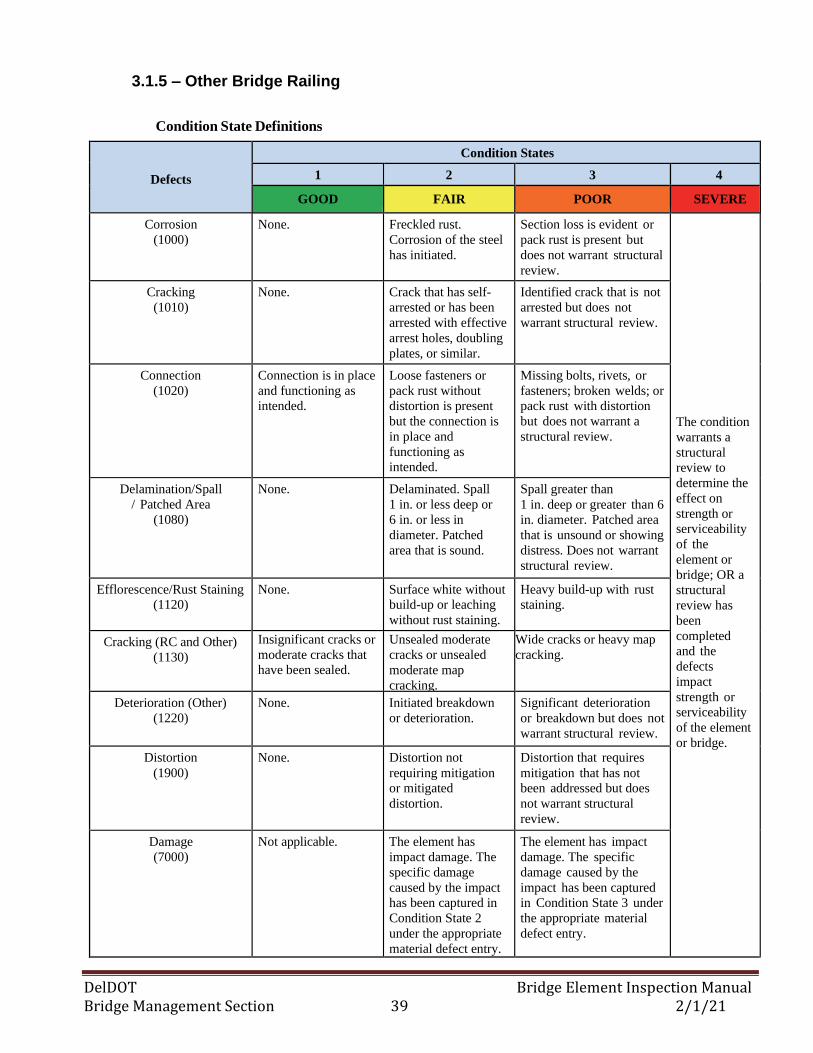
DelDOT Bridge Element Inspection Manual Bridge Management Section 39 2/1/21
3.1.5 – Other Bridge Railing
Condition State Definitions
Defects
Condition States
1 2 3 4
GOOD FAIR POOR SEVERE
Corrosion
(1000)
None. Freckled rust.
Corrosion of the steel
has initiated.
Section loss is evident or
pack rust is present but
does not warrant structural
review.
The condition
warrants a
structural
review to
determine the
effect on
strength or
serviceability
of the
element or
bridge; OR a
structural
review has
been
completed
and the
defects
impact
strength or
serviceability
of the element
or bridge.
Cracking
(1010)
None. Crack that has self-
arrested or has been
arrested with effective
arrest holes, doubling
plates, or similar.
Identified crack that is not
arrested but does not
warrant structural review.
Connection
(1020)
Connection is in place
and functioning as
intended.
Loose fasteners or
pack rust without
distortion is present
but the connection is
in place and
functioning as
intended.
Missing bolts, rivets, or
fasteners; broken welds; or
pack rust with distortion
but does not warrant a
structural review.
Delamination/Spall
/ Patched Area
(1080)
None. Delaminated. Spall
1 in. or less deep or
6 in. or less in
diameter. Patched
area that is sound.
Spall greater than
1 in. deep or greater than 6
in. diameter. Patched area
that is unsound or showing
distress. Does not warrant
structural review.
Efflorescence/Rust Staining
(1120)
None. Surface white without
build-up or leaching
without rust staining.
Heavy build-up with rust
staining.
Cracking (RC and Other)
(1130)
Insignificant cracks or
moderate cracks that
have been sealed.
Unsealed moderate
cracks or unsealed
moderate map
cracking.
Wide cracks or heavy map
cracking.
Deterioration (Other)
(1220)
None. Initiated breakdown
or deterioration.
Significant deterioration
or breakdown but does not
warrant structural review.
Distortion
(1900)
None. Distortion not
requiring mitigation
or mitigated
distortion.
Distortion that requires
mitigation that has not
been addressed but does
not warrant structural
review.
Damage
(7000)
Not applicable. The element has
impact damage. The
specific damage
caused by the impact
has been captured in
Condition State 2
under the appropriate
material defect entry.
The element has impact
damage. The specific
damage caused by the
impact has been captured
in Condition State 3 under
the appropriate material
defect entry.
DelDOT Bridge Element Inspection Manual Bridge Management Section 40 2/1/21
3.2—BRIDGE CURB, MEDIAN, SIDEWALK & DRAINS
3.2.1 – Reinforced Concrete Bridge Curb, Median & Sidewalk
Description: All types and shapes of reinforced concrete bridge curb, median and sidewalks. This
element only includes the curbs, medians and sidewalks that are placed directly on top of the bridge
deck, slab or culvert.
Element 521 (Concrete Protective Coating) shall be used for each individual element type that has a
protective coating applied to them. These coatings include silane/siloxane water proofers, crack
sealers such as High Molecular Weight Methacrylate (HMWM), or any top coat barrier that protects
concrete from deterioration and reinforcing steel from corrosion. Element 520 (Concrete Reinforcing
Steel Protective System) shall be used for each individual element type that has a corrosion
protection system installed. Protection systems may include cathodic protection or addition of
anodes to mitigate corrosion.
Element Title and Definition Units
856 Reinforced Concrete Sidewalk (L.F.)
.
859 Reinforced Concrete Curb (L.F.)
862 Reinforced Concrete Median (L.F.)
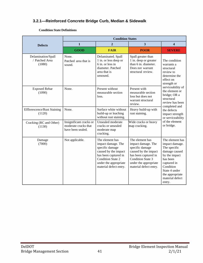
DelDOT Bridge Element Inspection Manual Bridge Management Section 41 2/1/21
3.2.1—Reinforced Concrete Bridge Curb, Median & Sidewalk
Condition State Definitions
Defects
Condition States
1 2 3 4
GOOD FAIR POOR SEVERE
Delamination/Spall
/ Patched Area
(1080)
None.
Patched area that is
sound.
Delaminated. Spall
1 in. or less deep or
6 in. or less in
diameter. Patched
area that is
unsound.
Spall greater than
1 in. deep or greater
than 6 in. diameter.
Does not warrant
structural review.
The condition
warrants a
structural
review to
determine the
effect on
strength or
serviceability of
the element or
bridge; OR a
structural
review has been
completed and
the defects
impact strength
or serviceability
of the element
or bridge.
Exposed Rebar
(1090)
None. Present without
measurable section
loss.
Present with
measurable section
loss but does not
warrant structural
review.
Efflorescence/Rust Staining
(1120)
None. Surface white without
build-up or leaching
without rust staining.
Heavy build-up with
rust staining.
Cracking (RC and Other)
(1130)
Insignificant cracks or
moderate cracks that
have been sealed.
Unsealed moderate
cracks or unsealed
moderate map
cracking.
Wide cracks or heavy
map cracking.
Damage
(7000)
Not applicable. The element has
impact damage. The
specific damage
caused by the impact
has been captured in
Condition State 2
under the appropriate
material defect entry.
The element has
impact damage. The
specific damage
caused by the impact
has been captured in
Condition State 3
under the appropriate
material defect entry.
The element has
impact damage.
The specific
damage caused
by the impact
has been
captured in
Condition
State 4 under
the appropriate
material defect
entry.
DelDOT Bridge Element Inspection Manual Bridge Management Section 42 2/1/21
3.2—BRIDGE CURBS, MEDIANS, SIDEWALKS & DRAINS
3.2.2 – Steel Bridge Curb, Median & Sidewalk
Description: All types and shapes of steel bridge curb, median and sidewalks. The correct steel
protective coating element shall be used.
Element Title and Definition Units
860 Steel Curb (L.F.)
863 Steel Median (L.F.)
867 Steel Sidewalk – Open Grid (L.F.)
868 Steel Sidewalk - Filled Grid (L.F.)
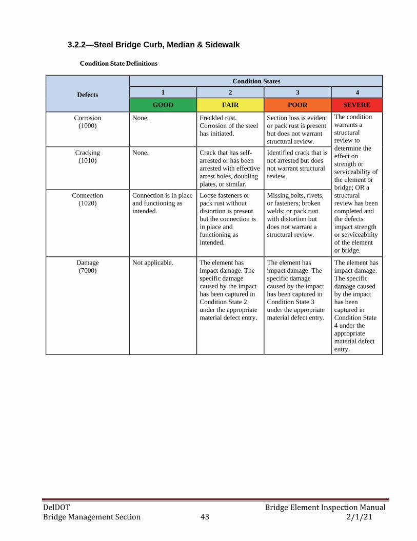
DelDOT Bridge Element Inspection Manual Bridge Management Section 43 2/1/21
3.2.2—Steel Bridge Curb, Median & Sidewalk
Condition State Definitions
Defects
Condition States
1 2 3 4
GOOD FAIR POOR SEVERE
Corrosion
(1000)
None. Freckled rust.
Corrosion of the steel
has initiated.
Section loss is evident
or pack rust is present
but does not warrant
structural review.
The condition
warrants a
structural
review to
determine the
effect on
strength or
serviceability of
the element or
bridge; OR a
structural
review has been
completed and
the defects
impact strength
or serviceability
of the element
or bridge.
Cracking
(1010)
None. Crack that has self-
arrested or has been
arrested with effective
arrest holes, doubling
plates, or similar.
Identified crack that is
not arrested but does
not warrant structural
review.
Connection
(1020)
Connection is in place
and functioning as
intended.
Loose fasteners or
pack rust without
distortion is present
but the connection is
in place and
functioning as
intended.
Missing bolts, rivets,
or fasteners; broken
welds; or pack rust
with distortion but
does not warrant a
structural review.
Damage
(7000)
Not applicable. The element has
impact damage. The
specific damage
caused by the impact
has been captured in
Condition State 2
under the appropriate
material defect entry.
The element has
impact damage. The
specific damage
caused by the impact
has been captured in
Condition State 3
under the appropriate
material defect entry.
The element has
impact damage.
The specific
damage caused
by the impact
has been
captured in
Condition State
4 under the
appropriate
material defect
entry.
DelDOT Bridge Element Inspection Manual Bridge Management Section 44 2/1/21
3.2—BRIDGE CURBS, MEDIANS, SIDEWALKS & DRAINS
3.2.3 – Timber Bridge Curb & Sidewalk
Description: All types and shapes of timber bridge curb and sidewalks.
Element Title and Definition Units
.
857 Timber Sidewalk (L.F.)
866 Timber Curb (L.F.)
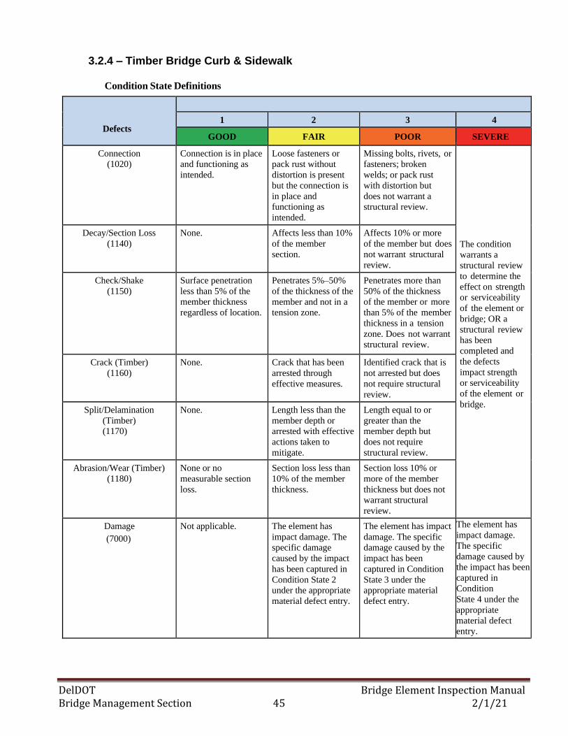
DelDOT Bridge Element Inspection Manual Bridge Management Section 45 2/1/21
3.2.4 – Timber Bridge Curb & Sidewalk
Condition State Definitions
Defects
1 2 3 4
GOOD FAIR POOR SEVERE
Connection
(1020)
Connection is in place
and functioning as
intended.
Loose fasteners or
pack rust without
distortion is present
but the connection is
in place and
functioning as
intended.
Missing bolts, rivets, or
fasteners; broken
welds; or pack rust
with distortion but
does not warrant a
structural review.
The condition
warrants a
structural review
to determine the
effect on strength
or serviceability
of the element or
bridge; OR a
structural review
has been
completed and
the defects
impact strength
or serviceability
of the element or
bridge.
Decay/Section Loss
(1140)
None. Affects less than 10%
of the member
section.
Affects 10% or more
of the member but does
not warrant structural
review.
Check/Shake
(1150)
Surface penetration
less than 5% of the
member thickness
regardless of location.
Penetrates 5%–50%
of the thickness of the
member and not in a
tension zone.
Penetrates more than
50% of the thickness
of the member or more
than 5% of the member
thickness in a tension
zone. Does not warrant
structural review.
Crack (Timber)
(1160)
None. Crack that has been
arrested through
effective measures.
Identified crack that is
not arrested but does
not require structural
review.
Split/Delamination
(Timber)
(1170)
None. Length less than the
member depth or
arrested with effective
actions taken to
mitigate.
Length equal to or
greater than the
member depth but
does not require
structural review.
Abrasion/Wear (Timber)
(1180)
None or no
measurable section
loss.
Section loss less than
10% of the member
thickness.
Section loss 10% or
more of the member
thickness but does not
warrant structural
review.
Damage
(7000)
Not applicable. The element has
impact damage. The
specific damage
caused by the impact
has been captured in
Condition State 2
under the appropriate
material defect entry.
The element has impact
damage. The specific
damage caused by the
impact has been
captured in Condition
State 3 under the
appropriate material
defect entry.
The element has
impact damage.
The specific
damage caused by
the impact has been
captured in
Condition
State 4 under the
appropriate
material defect
entry.
DelDOT Bridge Element Inspection Manual Bridge Management Section 46 2/1/21
3.2—BRIDGE CURBS, MEDIANS, SIDEWALKS & DRAINS
3.2.4 – Masonry Bridge Curb, Median & Sidewalk
Description: All types and shapes of masonry bridge curb and median. This does not include stamped
concrete or reinforced concrete with stone facing.
Element Title and Definition Units
.
858 Masonry Sidewalk (L.F.)
861 Masonry Curb (L.F.)
864 Masonry Median (L.F.)
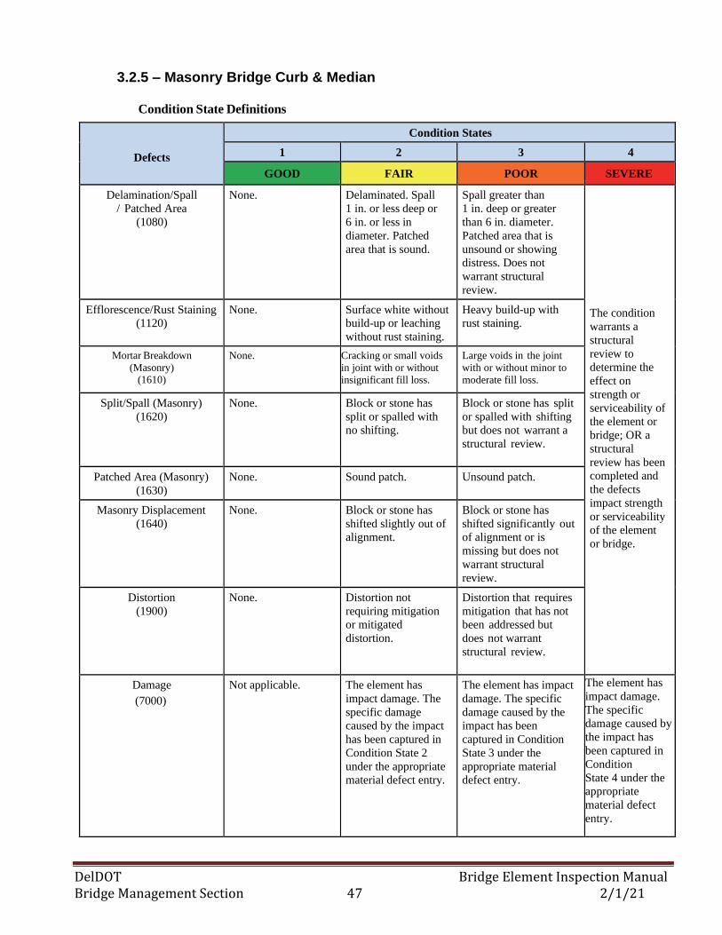
DelDOT Bridge Element Inspection Manual Bridge Management Section 47 2/1/21
3.2.5 – Masonry Bridge Curb & Median
Condition State Definitions
Defects
Condition States
1 2 3 4
GOOD FAIR POOR SEVERE
Delamination/Spall
/ Patched Area
(1080)
None. Delaminated. Spall
1 in. or less deep or
6 in. or less in
diameter. Patched
area that is sound.
Spall greater than
1 in. deep or greater
than 6 in. diameter.
Patched area that is
unsound or showing
distress. Does not
warrant structural
review.
The condition
warrants a
structural
review to
determine the
effect on
strength or
serviceability of
the element or
bridge; OR a
structural
review has been
completed and
the defects
impact strength
or serviceability
of the element
or bridge.
Efflorescence/Rust Staining
(1120)
None. Surface white without
build-up or leaching
without rust staining.
Heavy build-up with
rust staining.
Mortar Breakdown
(Masonry) (1610)
None. Cracking or small voids
in joint with or without
insignificant fill loss.
Large voids in the joint
with or without minor to
moderate fill loss.
Split/Spall (Masonry)
(1620)
None. Block or stone has
split or spalled with
no shifting.
Block or stone has split
or spalled with shifting
but does not warrant a
structural review.
Patched Area (Masonry)
(1630)
None. Sound patch. Unsound patch.
Masonry Displacement
(1640)
None. Block or stone has
shifted slightly out of
alignment.
Block or stone has
shifted significantly out
of alignment or is
missing but does not
warrant structural
review.
Distortion
(1900)
None. Distortion not
requiring mitigation
or mitigated
distortion.
Distortion that requires
mitigation that has not
been addressed but
does not warrant
structural review.
Damage
(7000)
Not applicable. The element has
impact damage. The
specific damage
caused by the impact
has been captured in
Condition State 2
under the appropriate
material defect entry.
The element has impact
damage. The specific
damage caused by the
impact has been
captured in Condition
State 3 under the
appropriate material
defect entry.
The element has
impact damage.
The specific
damage caused by
the impact has
been captured in
Condition
State 4 under the
appropriate
material defect
entry.
DelDOT Bridge Element Inspection Manual Bridge Management Section 48 2/1/21
3.2—BRIDGE CURBS, MEDIANS, SIDEWALKS & DRAINS
3.2.5 – Bridge Drains
Description: All types and shapes of bridge drains and drain system components including scuppers,
catch basins, downspouts and clean-outs. Only includes the drains and drain systems on the actual
bridge structure and does not include roadway drainage systems along the approach roadway to the
bridge.
Element Commentary: None
Element Title and Definition Units
.
865 Drains/Downspouts/Scuppers (EA)
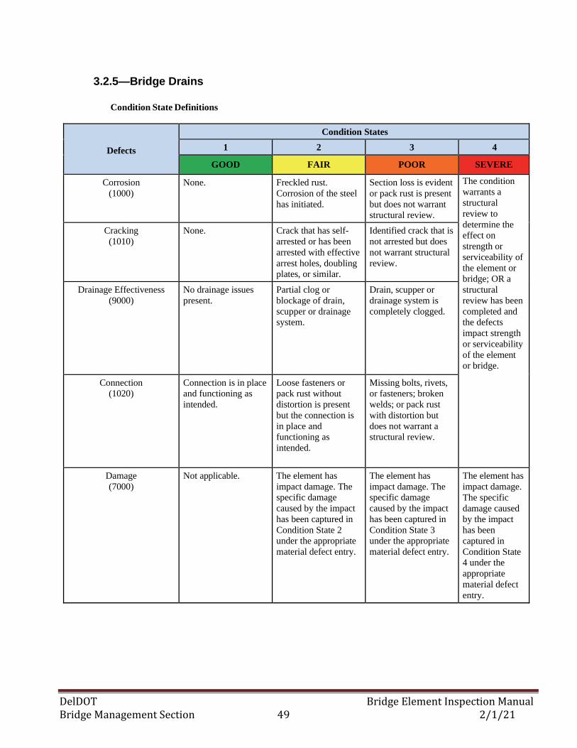
DelDOT Bridge Element Inspection Manual Bridge Management Section 49 2/1/21
3.2.5—Bridge Drains
Condition State Definitions
Defects
Condition States
1 2 3 4
GOOD FAIR POOR SEVERE
Corrosion
(1000)
None. Freckled rust.
Corrosion of the steel
has initiated.
Section loss is evident
or pack rust is present
but does not warrant
structural review.
The condition
warrants a
structural
review to
determine the
effect on
strength or
serviceability of
the element or
bridge; OR a
structural
review has been
completed and
the defects
impact strength
or serviceability
of the element
or bridge.
Cracking
(1010)
None. Crack that has self-
arrested or has been
arrested with effective
arrest holes, doubling
plates, or similar.
Identified crack that is
not arrested but does
not warrant structural
review.
Drainage Effectiveness
(9000)
No drainage issues
present.
Partial clog or
blockage of drain,
scupper or drainage
system.
Drain, scupper or
drainage system is
completely clogged.
Connection
(1020)
Connection is in place
and functioning as
intended.
Loose fasteners or
pack rust without
distortion is present
but the connection is
in place and
functioning as
intended.
Missing bolts, rivets,
or fasteners; broken
welds; or pack rust
with distortion but
does not warrant a
structural review.
Damage
(7000)
Not applicable. The element has
impact damage. The
specific damage
caused by the impact
has been captured in
Condition State 2
under the appropriate
material defect entry.
The element has
impact damage. The
specific damage
caused by the impact
has been captured in
Condition State 3
under the appropriate
material defect entry.
The element has
impact damage.
The specific
damage caused
by the impact
has been
captured in
Condition State
4 under the
appropriate
material defect
entry.
DelDOT Bridge Element Inspection Manual Bridge Management Section 50 2/1/21
3.3— APPROACH SLAB BRIDGE ELEMENTS
3.3.1 – Reinforced Concrete Approach Slab Bridge Element
Description: All reinforced concrete structural slabs that exist between the bridge abutment and
approach roadway pavement. If the approach slab has an asphaltic concrete overlay, then element 811,
Wearing Surfaces: Asphaltic Concrete Overlay, shall be created to account for deterioration in the
overlay.
Element Commentary
This element includes only structural slabs and does not include roadway concrete approaches.
Element Title and Definition Units
321 Reinforced Concrete Approach Slab (FT2)
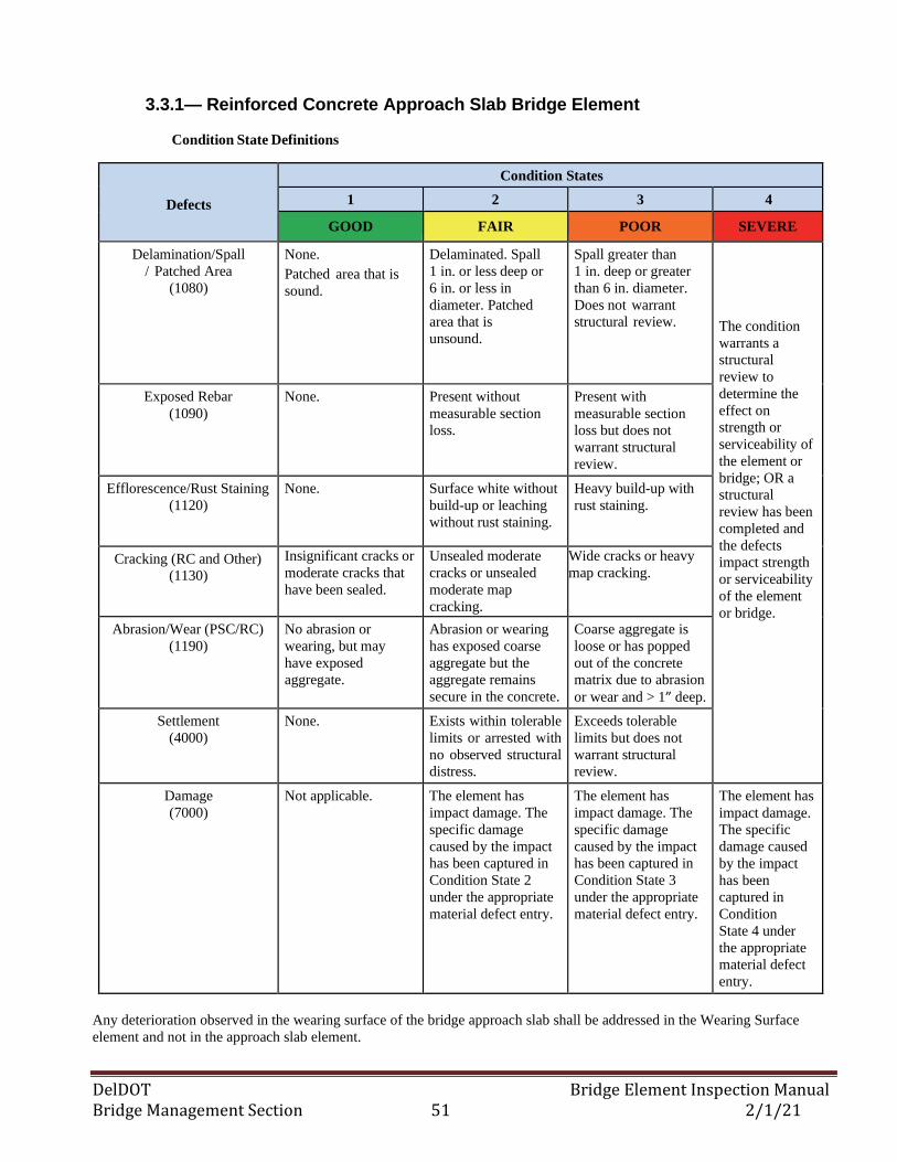
DelDOT Bridge Element Inspection Manual Bridge Management Section 51 2/1/21
3.3.1— Reinforced Concrete Approach Slab Bridge Element
Condition State Definitions
Defects
Condition States
1 2 3 4
GOOD FAIR POOR SEVERE
Delamination/Spall
/ Patched Area
(1080)
None.
Patched area that is
sound.
Delaminated. Spall
1 in. or less deep or
6 in. or less in
diameter. Patched
area that is
unsound.
Spall greater than
1 in. deep or greater
than 6 in. diameter.
Does not warrant
structural review.
The condition
warrants a
structural
review to
determine the
effect on
strength or
serviceability of
the element or
bridge; OR a
structural
review has been
completed and
the defects
impact strength
or serviceability
of the element
or bridge.
Exposed Rebar
(1090)
None. Present without
measurable section
loss.
Present with
measurable section
loss but does not
warrant structural
review.
Efflorescence/Rust Staining
(1120)
None. Surface white without
build-up or leaching
without rust staining.
Heavy build-up with
rust staining.
Cracking (RC and Other)
(1130)
Insignificant cracks or
moderate cracks that
have been sealed.
Unsealed moderate
cracks or unsealed
moderate map
cracking.
Wide cracks or heavy
map cracking.
Abrasion/Wear (PSC/RC)
(1190)
No abrasion or
wearing, but may
have exposed
aggregate.
Abrasion or wearing
has exposed coarse
aggregate but the
aggregate remains
secure in the concrete.
Coarse aggregate is
loose or has popped
out of the concrete
matrix due to abrasion
or wear and > 1” deep.
Settlement
(4000)
None. Exists within tolerable
limits or arrested with
no observed structural
distress.
Exceeds tolerable
limits but does not
warrant structural
review.
Damage
(7000)
Not applicable. The element has
impact damage. The
specific damage
caused by the impact
has been captured in
Condition State 2
under the appropriate
material defect entry.
The element has
impact damage. The
specific damage
caused by the impact
has been captured in
Condition State 3
under the appropriate
material defect entry.
The element has
impact damage.
The specific
damage caused
by the impact
has been
captured in
Condition
State 4 under
the appropriate
material defect
entry.
Any deterioration observed in the wearing surface of the bridge approach slab shall be addressed in the Wearing Surface
element and not in the approach slab element.
DelDOT Bridge Element Inspection Manual Bridge Management Section 52 2/1/21
3.3— APPROACH SLAB BRIDGE ELEMENTS
3.3.2 – Prestressed Concrete Approach Slab Bridge Element
Description: All prestressed concrete structural slabs that exist between the bridge abutment and
approach roadway pavement. If the approach slab has an asphaltic concrete overlay, then element 811,
Wearing Surfaces: Asphaltic Concrete Overlay, shall be created to account for deterioration in the
overlay.
Element Commentary
This element includes only structural slabs and does not include roadway concrete approaches.
Element Title and Definition Units
320 Prestressed Concrete Approach Slab (FT2)
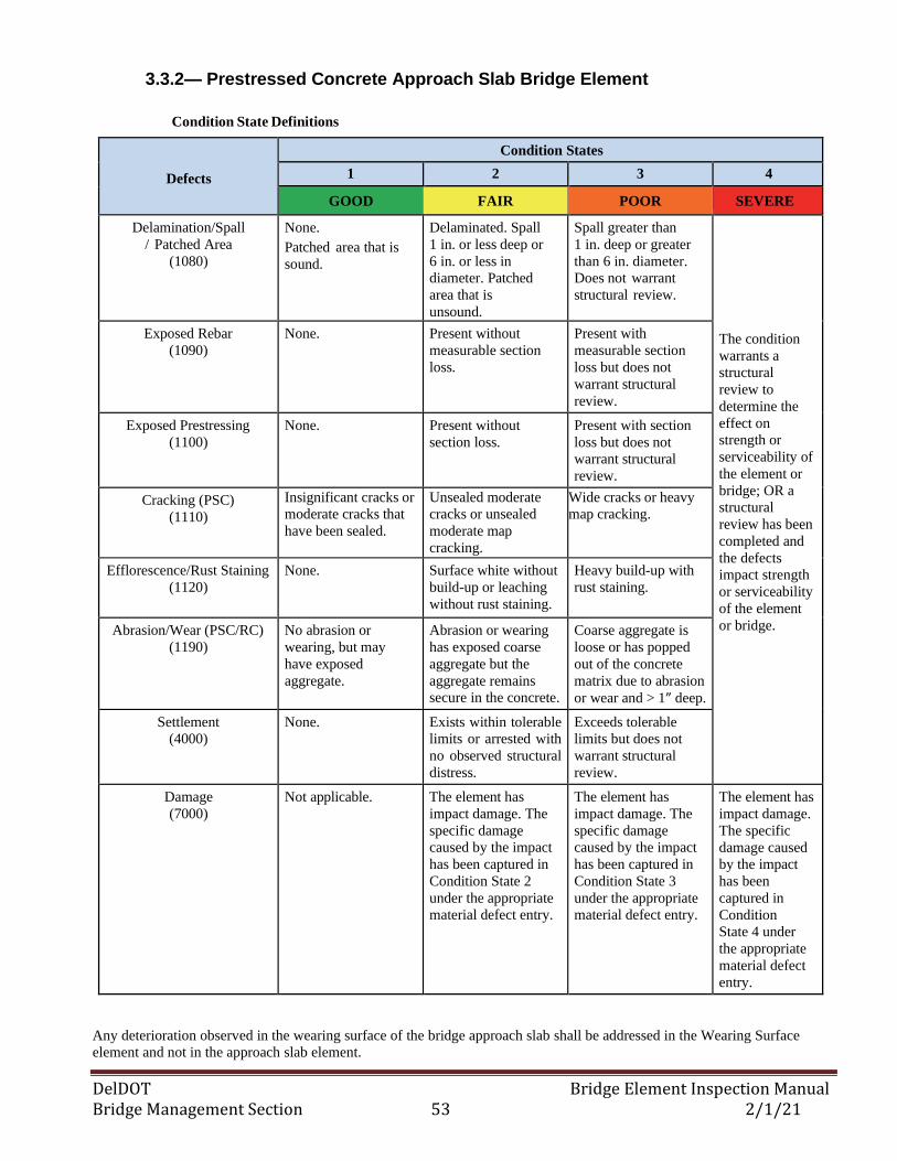
DelDOT Bridge Element Inspection Manual Bridge Management Section 53 2/1/21
3.3.2— Prestressed Concrete Approach Slab Bridge Element
Condition State Definitions
Defects
Condition States
1 2 3 4
GOOD FAIR POOR SEVERE
Delamination/Spall
/ Patched Area
(1080)
None.
Patched area that is
sound.
Delaminated. Spall
1 in. or less deep or
6 in. or less in
diameter. Patched
area that is
unsound.
Spall greater than
1 in. deep or greater
than 6 in. diameter.
Does not warrant
structural review.
The condition
warrants a
structural
review to
determine the
effect on
strength or
serviceability of
the element or
bridge; OR a
structural
review has been
completed and
the defects
impact strength
or serviceability
of the element
or bridge.
Exposed Rebar
(1090)
None. Present without
measurable section
loss.
Present with
measurable section
loss but does not
warrant structural
review.
Exposed Prestressing
(1100)
None. Present without
section loss.
Present with section
loss but does not
warrant structural
review.
Cracking (PSC)
(1110)
Insignificant cracks or
moderate cracks that
have been sealed.
Unsealed moderate
cracks or unsealed
moderate map
cracking.
Wide cracks or heavy
map cracking.
Efflorescence/Rust Staining
(1120)
None. Surface white without
build-up or leaching
without rust staining.
Heavy build-up with
rust staining.
Abrasion/Wear (PSC/RC)
(1190)
No abrasion or
wearing, but may
have exposed
aggregate.
Abrasion or wearing
has exposed coarse
aggregate but the
aggregate remains
secure in the concrete.
Coarse aggregate is
loose or has popped
out of the concrete
matrix due to abrasion
or wear and > 1” deep.
Settlement
(4000)
None. Exists within tolerable
limits or arrested with
no observed structural
distress.
Exceeds tolerable
limits but does not
warrant structural
review.
Damage
(7000)
Not applicable. The element has
impact damage. The
specific damage
caused by the impact
has been captured in
Condition State 2
under the appropriate
material defect entry.
The element has
impact damage. The
specific damage
caused by the impact
has been captured in
Condition State 3
under the appropriate
material defect entry.
The element has
impact damage.
The specific
damage caused
by the impact
has been
captured in
Condition
State 4 under
the appropriate
material defect
entry.
Any deterioration observed in the wearing surface of the bridge approach slab shall be addressed in the Wearing Surface
element and not in the approach slab element.
DelDOT Bridge Element Inspection Manual Bridge Management Section 54 2/1/21
3.4— DECK/SLAB BRIDGE ELEMENTS
3.4.1 – Reinforced Concrete Deck/Slab Bridge Elements
Description: All reinforced concrete bridge decks and slabs including R/C deck panels with or without
post-tensioning. If the deck or slab has a Non-Structural Overlay, added to the deck/slab, then the correct
wearing surface element type shall be created to account for deterioration in the overlay. The wearing
surface or overlay type may include asphaltic concrete (811), thin (810) and rigid (510) materials. If an
original bare concrete deck was milled and replaced with LMC or Class D concrete back to its original
depth, then that is considered Structural Resurfacing and a Wearing Surface Element shall not be
created.
Element Commentary
The deck evaluation is three-dimensional in nature with the defects observed on the top surface,
bottom surface, edges, or all; and being captured using the defined condition states. Deck/slab top
or bottom surfaces that are not visible for inspection shall be assessed based on the available visible
surface.
Deterioration in the bottom of the deck or slab element shall be documented in the deck element and
the Agency-Defined Element Smartflag element #839, Soffit.
Defects in the top surface of the Wearing Surface Element (Non-Structural Overlay) shall be
addressed in the corresponding Wearing Surface defect elements.
Element Title and Definition Units
12 Concrete Deck – Bare (FT2)
16 Reinforced Concrete Top Flange (FT2)
38 Reinforced Concrete Slab - Bare (FT2)
837 Reinforced Concrete Deck Under Fill (FT2)
838 Reinforced Concrete Slab Under Fill (FT2)
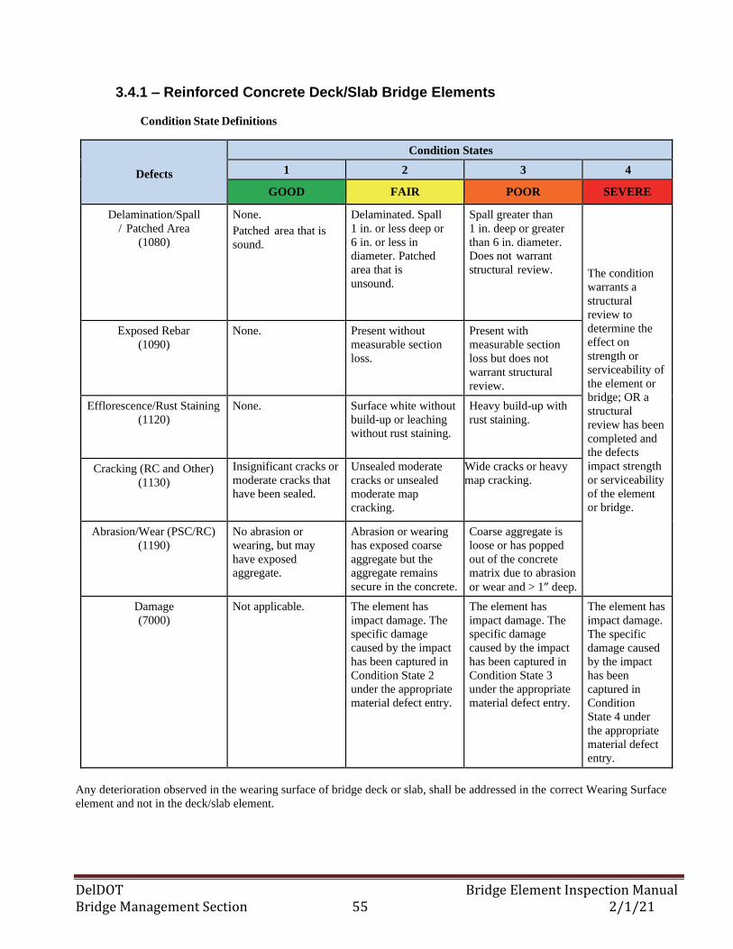
DelDOT Bridge Element Inspection Manual Bridge Management Section 55 2/1/21
3.4.1 – Reinforced Concrete Deck/Slab Bridge Elements
Condition State Definitions
Defects
Condition States
1 2 3 4
GOOD FAIR POOR SEVERE
Delamination/Spall
/ Patched Area
(1080)
None.
Patched area that is
sound.
Delaminated. Spall
1 in. or less deep or
6 in. or less in
diameter. Patched
area that is
unsound.
Spall greater than
1 in. deep or greater
than 6 in. diameter.
Does not warrant
structural review.
The condition
warrants a
structural
review to
determine the
effect on
strength or
serviceability of
the element or
bridge; OR a
structural
review has been
completed and
the defects
impact strength
or serviceability
of the element
or bridge.
Exposed Rebar
(1090)
None. Present without
measurable section
loss.
Present with
measurable section
loss but does not
warrant structural
review.
Efflorescence/Rust Staining
(1120)
None. Surface white without
build-up or leaching
without rust staining.
Heavy build-up with
rust staining.
Cracking (RC and Other)
(1130)
Insignificant cracks or
moderate cracks that
have been sealed.
Unsealed moderate
cracks or unsealed
moderate map
cracking.
Wide cracks or heavy
map cracking.
Abrasion/Wear (PSC/RC)
(1190)
No abrasion or
wearing, but may
have exposed
aggregate.
Abrasion or wearing
has exposed coarse
aggregate but the
aggregate remains
secure in the concrete.
Coarse aggregate is
loose or has popped
out of the concrete
matrix due to abrasion
or wear and > 1” deep.
Damage
(7000)
Not applicable. The element has
impact damage. The
specific damage
caused by the impact
has been captured in
Condition State 2
under the appropriate
material defect entry.
The element has
impact damage. The
specific damage
caused by the impact
has been captured in
Condition State 3
under the appropriate
material defect entry.
The element has
impact damage.
The specific
damage caused
by the impact
has been
captured in
Condition
State 4 under
the appropriate
material defect
entry.
Any deterioration observed in the wearing surface of bridge deck or slab, shall be addressed in the correct Wearing Surface
element and not in the deck/slab element.
DelDOT Bridge Element Inspection Manual Bridge Management Section 56 2/1/21
3.4— DECK/SLAB BRIDGE ELEMENTS
3.4.2 – Prestressed Concrete Deck Bridge Elements
Description: All prestressed concrete bridge decks. This doesnot include R/C deck panels that are post-
tensioned. If the deck has a Non-Structural Overlay, then the correct wearing surface element type shall
be created to account for deterioration in the overlay. The wearing surface or overlay type may include
asphaltic concrete (811), thin (810) and rigid (510) materials. If an original bare concrete deck was
milled and replaced with LMC or Class D concrete back to its original depth, then that is considered
Structural Resurfacing and a Wearing Surface Element shall not be created.
Element Commentary
The deck evaluation is three-dimensional in nature with the defects observed on the top surface,
bottom surface, edges, or all; and being captured using the defined condition states. Deck top or
bottom surfaces that are not visible for inspection shall be assessed based on the available visible
surface.
Deterioration in the bottom of the deck element shall be documented in the deck element and the
Agency-Defined Element Smartflag element #839, Soffit.
Defects in the top surface of the Wearing Surface Element (Non-Structural Overlay) shall be
addressed in the corresponding Wearing Surface defect elements.
Element Title and Definition Units
13 Prestressed Concrete Deck (FT2)
15 Prestressed Concrete Top Flange (FT2)
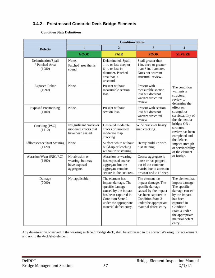
DelDOT Bridge Element Inspection Manual Bridge Management Section 57 2/1/21
3.4.2 – Prestressed Concrete Deck Bridge Elements
Condition State Definitions
Condition States 1 2 3 4 Defects
GOOD FAIR POOR SEVERE
Delamination/Spall
/ Patched Area
(1080)
None.
Patched area that is
sound.
Delaminated. Spall
1 in. or less deep or
6 in. or less in
diameter. Patched
area that is
unsound.
Spall greater than
1 in. deep or greater
than 6 in. diameter.
Does not warrant
structural review.
The condition
warrants a
structural
review to
determine the
effect on
strength or
serviceability of
the element or
bridge; OR a
structural
review has been
completed and
the defects
impact strength
or serviceability
of the element
or bridge.
Exposed Rebar
(1090)
None. Present without
measurable section
loss.
Present with
measurable section
loss but does not
warrant structural
review.
Exposed Prestressing
(1100)
None. Present without
section loss.
Present with section
loss but does not
warrant structural
review.
Cracking (PSC)
(1110)
Insignificant cracks or
moderate cracks that
have been sealed.
Unsealed moderate
cracks or unsealed
moderate map
cracking.
Wide cracks or heavy
map cracking.
Efflorescence/Rust Staining
(1120)
None. Surface white without
build-up or leaching
without rust staining.
Heavy build-up with
rust staining.
Abrasion/Wear (PSC/RC)
(1190)
No abrasion or
wearing, but may
have exposed
aggregate.
Abrasion or wearing
has exposed coarse
aggregate but the
aggregate remains
secure in the concrete.
Coarse aggregate is
loose or has popped
out of the concrete
matrix due to abrasion
or wear and > 1” deep.
Damage
(7000)
Not applicable. The element has
impact damage. The
specific damage
caused by the impact
has been captured in
Condition State 2
under the appropriate
material defect entry.
The element has
impact damage. The
specific damage
caused by the impact
has been captured in
Condition State 3
under the appropriate
material defect entry.
The element has
impact damage.
The specific
damage caused
by the impact
has been
captured in
Condition
State 4 under
the appropriate
material defect
entry.
Any deterioration observed in the wearing surface of bridge deck, shall be addressed in the correct Wearing Surface element
and not in the deck/slab element.
DelDOT Bridge Element Inspection Manual Bridge Management Section 58 2/1/21
3.4— DECK/SLAB BRIDGE ELEMENTS
3.4.3 – Timber Deck/Slab Bridge Elements
Description: All timber structural deck and slabs. If the timber deck or slab has an overlay, then the
correct wearing surface element shall be created to account for deterioration in the overlay. The
wearing surface or overlay type may include asphaltic concrete (811) or timber planking (812).
Element Commentary
The deck evaluation is three-dimensional in nature with the defects observed on the top surface,
bottom surface, edges, or all; and being captured using the defined condition states. Deck/slab top or
bottom surfaces that are not visible for inspection shall be assessed based on the available visible
surface.
Element Title and Definition Units
31 Timber Deck (FT2)
54 Timber Slab (FT2)
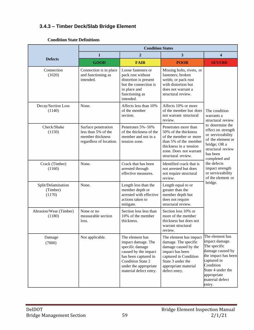
DelDOT Bridge Element Inspection Manual Bridge Management Section 59 2/1/21
3.4.3 – Timber Deck/Slab Bridge Element
Condition State Definitions
Defects
Condition States
1 2 3 4
GOOD FAIR POOR SEVERE
Connection
(1020)
Connection is in place
and functioning as
intended.
Loose fasteners or
pack rust without
distortion is present
but the connection is
in place and
functioning as
intended.
Missing bolts, rivets, or
fasteners; broken
welds; or pack rust
with distortion but
does not warrant a
structural review.
The condition
warrants a
structural review
to determine the
effect on strength
or serviceability
of the element or
bridge; OR a
structural review
has been
completed and
the defects
impact strength
or serviceability
of the element or
bridge.
Decay/Section Loss
(1140)
None. Affects less than 10%
of the member
section.
Affects 10% or more
of the member but does
not warrant structural
review.
Check/Shake
(1150)
Surface penetration
less than 5% of the
member thickness
regardless of location.
Penetrates 5%–50%
of the thickness of the
member and not in a
tension zone.
Penetrates more than
50% of the thickness
of the member or more
than 5% of the member
thickness in a tension
zone. Does not warrant
structural review.
Crack (Timber)
(1160)
None. Crack that has been
arrested through
effective measures.
Identified crack that is
not arrested but does
not require structural
review.
Split/Delamination
(Timber)
(1170)
None. Length less than the
member depth or
arrested with effective
actions taken to
mitigate.
Length equal to or
greater than the
member depth but
does not require
structural review.
Abrasion/Wear (Timber)
(1180)
None or no
measurable section
loss.
Section loss less than
10% of the member
thickness.
Section loss 10% or
more of the member
thickness but does not
warrant structural
review.
Damage
(7000)
Not applicable. The element has
impact damage. The
specific damage
caused by the impact
has been captured in
Condition State 2
under the appropriate
material defect entry.
The element has impact
damage. The specific
damage caused by the
impact has been
captured in Condition
State 3 under the
appropriate material
defect entry.
The element has
impact damage.
The specific
damage caused by
the impact has been
captured in
Condition
State 4 under the
appropriate
material defect
entry.
DelDOT Bridge Element Inspection Manual Bridge Management Section 60 2/1/21
3.4— DECK/SLAB BRIDGE ELEMENTS
3.4.4 – Steel Deck Bridge Elements
Description: All steel structural decks including steel deck with open grid, steel deck with concrete
filled grid and steel corrugated decks. Doesn’t include R/C Decks with steel stay-in-place forms.
Element Commentary
The deck evaluation is three-dimensional in nature with the defects observed on the top surface,
bottom surface, edges, or all; and being captured using the defined condition states. Deck top or
bottom surfaces that are not visible for inspection shall be assessed based on the available visible
surface.
Element Title and Definition Units
28 Steel Deck with Open Grid (FT2)
29 Steel Deck with Concrete Filled Grid (FT2)
30 Steel Deck Corrugated (FT2)
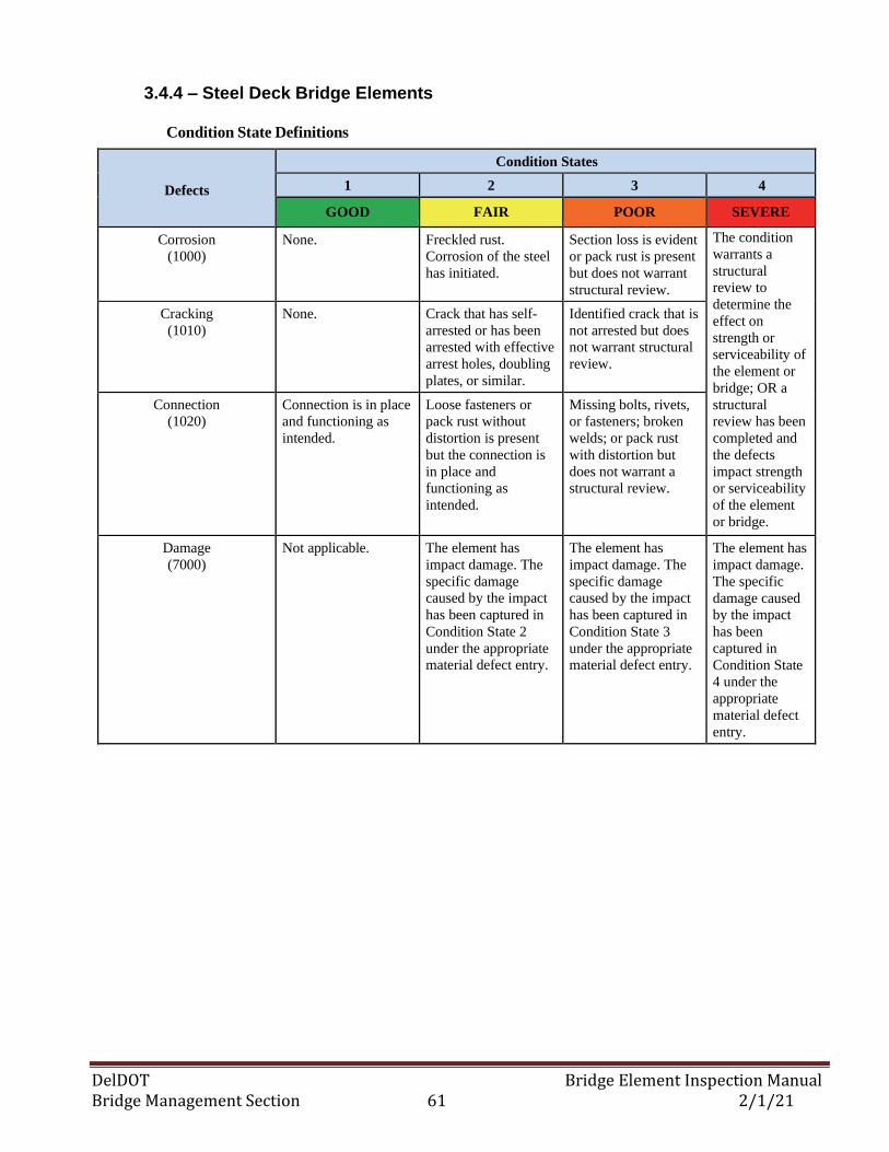
DelDOT Bridge Element Inspection Manual Bridge Management Section 61 2/1/21
3.4.4 – Steel Deck Bridge Elements
Condition State Definitions
Defects
Condition States
1 2 3 4
GOOD FAIR POOR SEVERE
Corrosion
(1000)
None. Freckled rust.
Corrosion of the steel
has initiated.
Section loss is evident
or pack rust is present
but does not warrant
structural review.
The condition
warrants a
structural
review to
determine the
effect on
strength or
serviceability of
the element or
bridge; OR a
structural
review has been
completed and
the defects
impact strength
or serviceability
of the element
or bridge.
Cracking
(1010)
None. Crack that has self-
arrested or has been
arrested with effective
arrest holes, doubling
plates, or similar.
Identified crack that is
not arrested but does
not warrant structural
review.
Connection
(1020)
Connection is in place
and functioning as
intended.
Loose fasteners or
pack rust without
distortion is present
but the connection is
in place and
functioning as
intended.
Missing bolts, rivets,
or fasteners; broken
welds; or pack rust
with distortion but
does not warrant a
structural review.
Damage
(7000)
Not applicable. The element has
impact damage. The
specific damage
caused by the impact
has been captured in
Condition State 2
under the appropriate
material defect entry.
The element has
impact damage. The
specific damage
caused by the impact
has been captured in
Condition State 3
under the appropriate
material defect entry.
The element has
impact damage.
The specific
damage caused
by the impact
has been
captured in
Condition State
4 under the
appropriate
material defect
entry.
DelDOT Bridge Element Inspection Manual Bridge Management Section 62 2/1/21
3.4— DECK/SLAB BRIDGE ELEMENTS
3.4.5 – Other Deck/Slab Bridge Elements
Description: All bridge decks/slabs constructed of composite (plastic) materials regardless of the
wearing surface or protection systems used. . If the deck or slab has an overlay, then the correct
wearing surface element shall be created to account for deterioration in the overlay. The wearing surface
or overlay type may include asphaltic concrete (811), thin (810) and rigid (510) materials.
Element Commentary
The deck evaluation is three-dimensional in nature with the defects observed on the top surface,
bottom surface, edges, or all; and being captured using the defined condition states. Deck/slab top
or bottom surfaces that are not visible for inspection shall be assessed based on the available visible
surface.
Element Title and Definition Units
60 Other Deck (FT2)
65 Other Slab (FT2)
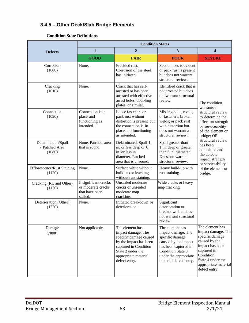
DelDOT Bridge Element Inspection Manual Bridge Management Section 63 2/1/21
3.4.5 – Other Deck/Slab Bridge Elements
Condition State Definitions
Defects
Condition States
1 2 3 4
GOOD FAIR POOR SEVERE
Corrosion
(1000)
None. Freckled rust.
Corrosion of the steel
has initiated.
Section loss is evident
or pack rust is present
but does not warrant
structural review.
The condition
warrants a
structural review
to determine the
effect on strength
or serviceability
of the element or
bridge; OR a
structural review
has been
completed and
the defects
impact strength
or serviceability
of the element or
bridge.
Cracking
(1010)
None. Crack that has self-
arrested or has been
arrested with effective
arrest holes, doubling
plates, or similar.
Identified crack that is
not arrested but does
not warrant structural
review.
Connection
(1020)
Connection is in
place and
functioning as
intended.
Loose fasteners or
pack rust without
distortion is present but
the connection is in
place and functioning
as intended.
Missing bolts, rivets,
or fasteners; broken
welds; or pack rust
with distortion but
does not warrant a
structural review.
Delamination/Spall
/ Patched Area
(1080)
None. Patched area
that is sound.
Delaminated. Spall 1
in. or less deep or 6
in. or less in
diameter. Patched
area that is unsound.
Spall greater than
1 in. deep or greater
than 6 in. diameter.
Does not warrant
structural review.
Efflorescence/Rust Staining
(1120)
None. Surface white without
build-up or leaching
without rust staining.
Heavy build-up with
rust staining.
Cracking (RC and Other)
(1130)
Insignificant cracks
or moderate cracks
that have been
sealed.
Unsealed moderate
cracks or unsealed
moderate map
cracking.
Wide cracks or heavy
map cracking.
Deterioration (Other)
(1220)
None. Initiated breakdown or
deterioration.
Significant
deterioration or
breakdown but does
not warrant structural
review.
Damage
(7000)
Not applicable. The element has
impact damage. The
specific damage caused
by the impact has been
captured in Condition
State 2 under the
appropriate material
defect entry.
The element has
impact damage. The
specific damage
caused by the impact
has been captured in
Condition State 3
under the appropriate
material defect entry.
The element has
impact damage. The
specific damage
caused by the
impact has been
captured in
Condition
State 4 under the
appropriate material
defect entry.
DelDOT Bridge Element Inspection Manual Bridge Management Section 64 2/1/21
3.4— DECK/SLAB BRIDGE ELEMENTS
3.4.6 – A/C Overlay Bridge Element
Description: All reinforced concrete frame or box culverts that have overlays made with asphaltic
concrete directly on top.
Element Commentary
The A/C Overlay Surface Element uses the same defect elements as that of the Wearing Surface type
of Bridge Management Elements.
Element Title and Definition Units
801 Asphaltic Concrete Overlay Surface (FT2)
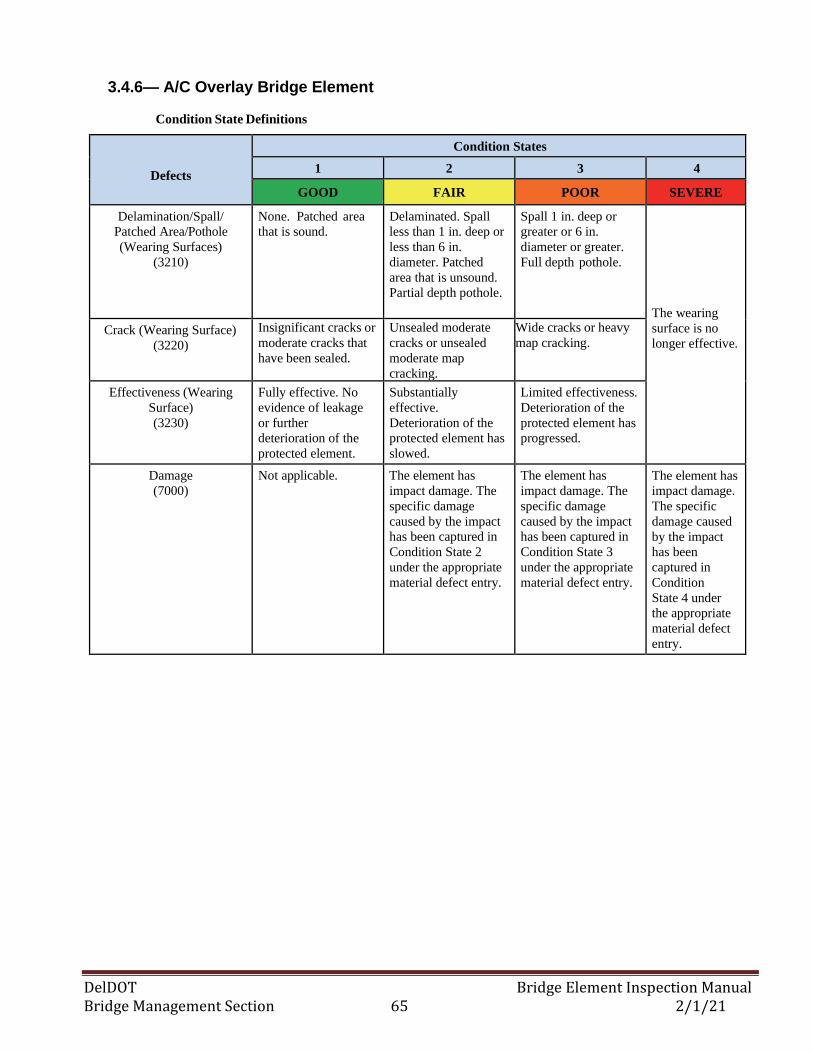
DelDOT Bridge Element Inspection Manual Bridge Management Section 65 2/1/21
3.4.6— A/C Overlay Bridge Element
Condition State Definitions
Defects
Condition States
1 2 3 4
GOOD FAIR POOR SEVERE
Delamination/Spall/
Patched Area/Pothole
(Wearing Surfaces)
(3210)
None. Patched area
that is sound.
Delaminated. Spall
less than 1 in. deep or
less than 6 in.
diameter. Patched
area that is unsound.
Partial depth pothole.
Spall 1 in. deep or
greater or 6 in.
diameter or greater.
Full depth pothole.
The wearing
surface is no
longer effective. Crack (Wearing Surface)
(3220)
Insignificant cracks or
moderate cracks that
have been sealed.
Unsealed moderate
cracks or unsealed
moderate map
cracking.
Wide cracks or heavy
map cracking.
Effectiveness (Wearing
Surface)
(3230)
Fully effective. No
evidence of leakage
or further
deterioration of the
protected element.
Substantially
effective.
Deterioration of the
protected element has
slowed.
Limited effectiveness.
Deterioration of the
protected element has
progressed.
Damage
(7000)
Not applicable. The element has
impact damage. The
specific damage
caused by the impact
has been captured in
Condition State 2
under the appropriate
material defect entry.
The element has
impact damage. The
specific damage
caused by the impact
has been captured in
Condition State 3
under the appropriate
material defect entry.
The element has
impact damage.
The specific
damage caused
by the impact
has been
captured in
Condition
State 4 under
the appropriate
material defect
entry.
DelDOT Bridge Element Inspection Manual Bridge Management Section 66 2/1/21
3.5— BRIDGE JOINT ELEMENTS
3.5.1 – Bridge Joints w/ Gland
Description: Those expansion joint devices which utilize a neoprene type waterproof gland with some
type of metal extrusion or other system to anchor the gland.
Element Title and Definition Units
300 Strip Seal Expansion Joint (L.F.)
302 Compression Joint Seal (L.F.)
303 Assembly Joint Seal (modular) (L.F.)
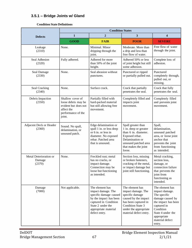
DelDOT Bridge Element Inspection Manual Bridge Management Section 67 2/1/21
3.5.1 – Bridge Joints w/ Gland
Condition State Definitions
Defects
Condition States
1 2 3 4
GOOD FAIR POOR SEVERE
Leakage
(2310)
None. Minimal. Minor
dripping through the
joint.
Moderate. More than
a drip and less than
free flow of water.
Free flow of water
through the joint.
Seal Adhesion
(2320)
Fully adhered. Adhered for more
than 50% of the joint
height.
Adhered 50% or less
of joint height but still
some adhesion.
Complete loss of
adhesion.
Seal Damage
(2330)
None. Seal abrasion without
punctures.
Punctured or ripped
or partially pulled out.
Punctured
completely through,
pulled out, or
missing.
Seal Cracking
(2340)
None. Surface crack. Crack that partially
penetrates the seal.
Crack that fully
penetrates the seal.
Debris Impaction
(2350)
Shallow cover of
loose debris may be
evident but does not
affect the
performance of the
joint.
Partially filled with
hard-packed material
but still allowing free
movement.
Completely filled and
impacts joint
movement.
Completely filled
and prevents joint
movement.
Adjacent Deck or Header
(2360) Sound. No spall,
delamination, or
unsound patch.
Edge delamination or
spall 1 in. or less deep
or 6 in. or less in
diameter. No exposed
rebar. Patched area
that is unsound.
Spall greater than
1 in. deep or greater
than 6 in. diameter.
Exposed rebar.
Delamination or
unsound patched area
that makes the joint
loose.
Spall,
delamination,
unsound patched
area, or loose joint
anchor that
prevents the joint
from functioning
as intended.
Metal Deterioration or
Damage
(2370)
None. Freckled rust; metal
has no cracks, or
impact damage.
Connection may be
loose but functioning
as intended.
Section loss, missing
or broken fasteners,
cracking of the metal,
or impact damage but
joint still functioning.
Metal cracking,
section loss,
damage, or
connection failure
that prevents the
joint from
functioning as
intended.
Damage
(7000)
Not applicable. The element has
impact damage. The
specific damage caused
by the impact has been
captured in Condition
State 2 under the
appropriate material
defect entry.
The element has
impact damage. The
specific damage
caused by the impact
has been captured in
Condition State 3
under the appropriate
material defect entry.
The element has
impact damage.
The specific
damage caused by
the impact has been
captured in
Condition
State 4 under the
appropriate
material defect
entry.
DelDOT Bridge Element Inspection Manual Bridge Management Section 68 2/1/21
3.5— BRIDGE JOINT ELEMENTS
3.5.2 – Bridge Joints w/o Gland
Description: Those expansion joint devices that are open and not sealed, including finger, sliding plate
and open joints.
Element Commentary
Any vertical or lateral misalignment of the joint shall be noted in the Alignment (2220) defect element
comments. If the misalignment is related to the bearings than the inspector shall also note this and refer
to bearing element for more details.
Element Title and Definition Units
304 Open Expansion Joint (L.F.)
305 Assembly Joint w/o Seal (modular) (L.F.)
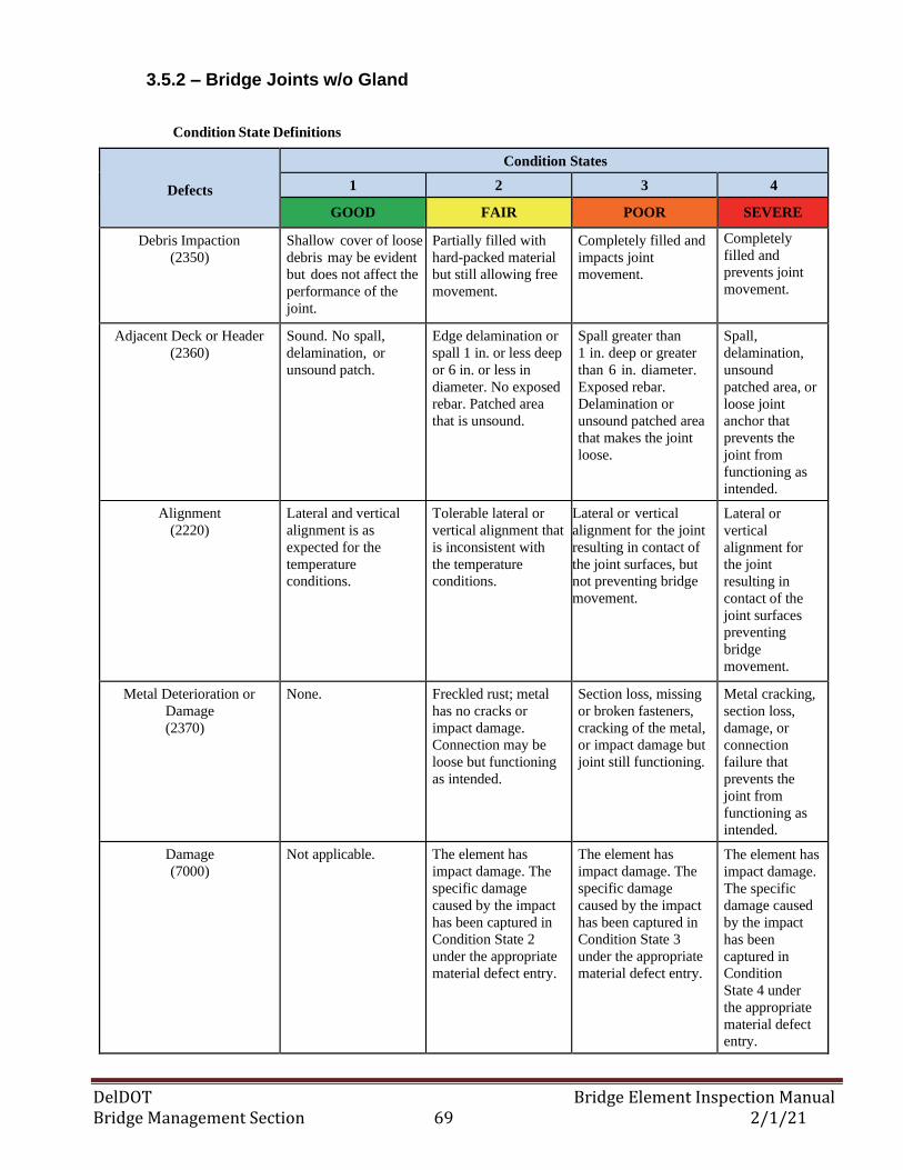
DelDOT Bridge Element Inspection Manual Bridge Management Section 69 2/1/21
3.5.2 – Bridge Joints w/o Gland
Condition State Definitions
Defects
Condition States
1 2 3 4
GOOD FAIR POOR SEVERE
Debris Impaction
(2350)
Shallow cover of loose
debris may be evident
but does not affect the
performance of the
joint.
Partially filled with
hard-packed material
but still allowing free
movement.
Completely filled and
impacts joint
movement.
Completely
filled and
prevents joint
movement.
Adjacent Deck or Header
(2360)
Sound. No spall,
delamination, or
unsound patch.
Edge delamination or
spall 1 in. or less deep
or 6 in. or less in
diameter. No exposed
rebar. Patched area
that is unsound.
Spall greater than
1 in. deep or greater
than 6 in. diameter.
Exposed rebar.
Delamination or
unsound patched area
that makes the joint
loose.
Spall,
delamination,
unsound
patched area, or
loose joint
anchor that
prevents the
joint from
functioning as
intended.
Alignment
(2220)
Lateral and vertical
alignment is as
expected for the
temperature
conditions.
Tolerable lateral or
vertical alignment that
is inconsistent with
the temperature
conditions.
Lateral or vertical
alignment for the joint
resulting in contact of
the joint surfaces, but
not preventing bridge
movement.
Lateral or
vertical
alignment for
the joint
resulting in
contact of the
joint surfaces
preventing
bridge
movement.
Metal Deterioration or
Damage
(2370)
None. Freckled rust; metal
has no cracks or
impact damage.
Connection may be
loose but functioning
as intended.
Section loss, missing
or broken fasteners,
cracking of the metal,
or impact damage but
joint still functioning.
Metal cracking,
section loss,
damage, or
connection
failure that
prevents the
joint from
functioning as
intended.
Damage
(7000)
Not applicable. The element has
impact damage. The
specific damage
caused by the impact
has been captured in
Condition State 2
under the appropriate
material defect entry.
The element has
impact damage. The
specific damage
caused by the impact
has been captured in
Condition State 3
under the appropriate
material defect entry.
The element has
impact damage.
The specific
damage caused
by the impact
has been
captured in
Condition
State 4 under
the appropriate
material defect
entry.
DelDOT Bridge Element Inspection Manual Bridge Management Section 70 2/1/21
3.5— BRIDGE JOINT ELEMENTS
3.5.3 – Bridge Joints w/ Pourable or Asphaltic Seal
Description: Those joints with a pourable or asphaltic type of seal with or without a backer rod.
Element Title and Definition Units
301 Pourable Joint Seal (L.F.)
809 Asphaltic Plug Joint (L.F.)
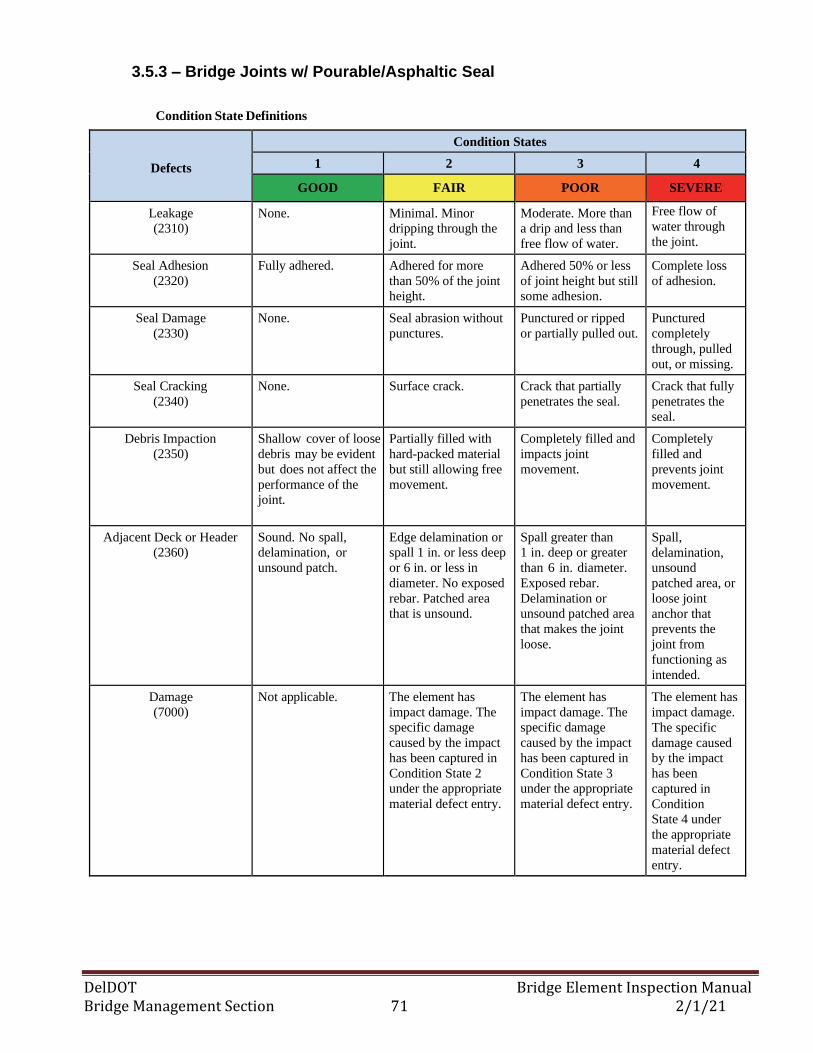
DelDOT Bridge Element Inspection Manual Bridge Management Section 71 2/1/21
3.5.3 – Bridge Joints w/ Pourable/Asphaltic Seal
Condition State Definitions
Defects
Condition States
1 2 3 4
GOOD FAIR POOR SEVERE
Leakage
(2310)
None. Minimal. Minor
dripping through the
joint.
Moderate. More than
a drip and less than
free flow of water.
Free flow of
water through
the joint.
Seal Adhesion
(2320)
Fully adhered. Adhered for more
than 50% of the joint
height.
Adhered 50% or less
of joint height but still
some adhesion.
Complete loss
of adhesion.
Seal Damage
(2330)
None. Seal abrasion without
punctures.
Punctured or ripped
or partially pulled out.
Punctured
completely
through, pulled
out, or missing.
Seal Cracking
(2340)
None. Surface crack. Crack that partially
penetrates the seal.
Crack that fully
penetrates the
seal.
Debris Impaction
(2350)
Shallow cover of loose
debris may be evident
but does not affect the
performance of the
joint.
Partially filled with
hard-packed material
but still allowing free
movement.
Completely filled and
impacts joint
movement.
Completely
filled and
prevents joint
movement.
Adjacent Deck or Header
(2360)
Sound. No spall,
delamination, or
unsound patch.
Edge delamination or
spall 1 in. or less deep
or 6 in. or less in
diameter. No exposed
rebar. Patched area
that is unsound.
Spall greater than
1 in. deep or greater
than 6 in. diameter.
Exposed rebar.
Delamination or
unsound patched area
that makes the joint
loose.
Spall,
delamination,
unsound
patched area, or
loose joint
anchor that
prevents the
joint from
functioning as
intended.
Damage
(7000)
Not applicable. The element has
impact damage. The
specific damage
caused by the impact
has been captured in
Condition State 2
under the appropriate
material defect entry.
The element has
impact damage. The
specific damage
caused by the impact
has been captured in
Condition State 3
under the appropriate
material defect entry.
The element has
impact damage.
The specific
damage caused
by the impact
has been
captured in
Condition
State 4 under
the appropriate
material defect
entry.
DelDOT Bridge Element Inspection Manual Bridge Management Section 72 2/1/21
3.5— BRIDGE JOINT ELEMENTS
3.5.4 – Bridge Joint Other
Description: Only those joints that are not defined by any other joint element.
Element Title and Definition Units
306 Other Joint (L.F.)
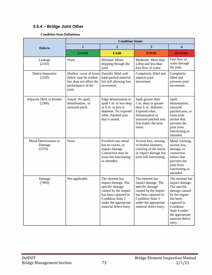
DelDOT Bridge Element Inspection Manual Bridge Management Section 73 2/1/21
3.5.4 – Bridge Joint Other
Condition State Definitions
Defects
Condition States
1 2 3 4
GOOD FAIR POOR SEVERE
Leakage
(2310)
None. Minimal. Minor
dripping through the
joint.
Moderate. More than
a drip and less than
free flow of water.
Free flow of
water through
the joint.
Debris Impaction
(2350)
Shallow cover of loose
debris may be evident
but does not affect the
performance of the
joint.
Partially filled with
hard-packed material
but still allowing free
movement.
Completely filled and
impacts joint
movement.
Completely
filled and
prevents joint
movement.
Adjacent Deck or Header
(2360)
Sound. No spall,
delamination, or
unsound patch.
Edge delamination or
spall 1 in. or less deep
or 6 in. or less in
diameter. No exposed
rebar. Patched area
that is sound.
Spall greater than
1 in. deep or greater
than 6 in. diameter.
Exposed rebar.
Delamination or
unsound patched area
that makes the joint
loose.
Spall,
delamination,
unsound
patched area, or
loose joint
anchor that
prevents the
joint from
functioning as
intended.
Metal Deterioration or
Damage
(2370)
None. Freckled rust; metal
has no cracks, or
impact damage.
Connection may be
loose but functioning
as intended.
Section loss, missing
or broken fasteners,
cracking of the metal,
or impact damage but
joint still functioning.
Metal cracking,
section loss,
damage, or
connection
failure that
prevents the
joint from
functioning as
intended.
Damage
(7000)
Not applicable. The element has
impact damage. The
specific damage
caused by the impact
has been captured in
Condition State 2
under the appropriate
material defect entry.
The element has
impact damage. The
specific damage
caused by the impact
has been captured in
Condition State 3
under the appropriate
material defect entry.
The element has
impact damage.
The specific
damage caused
by the impact
has been
captured in
Condition
State 4 under
the appropriate
material defect
entry.
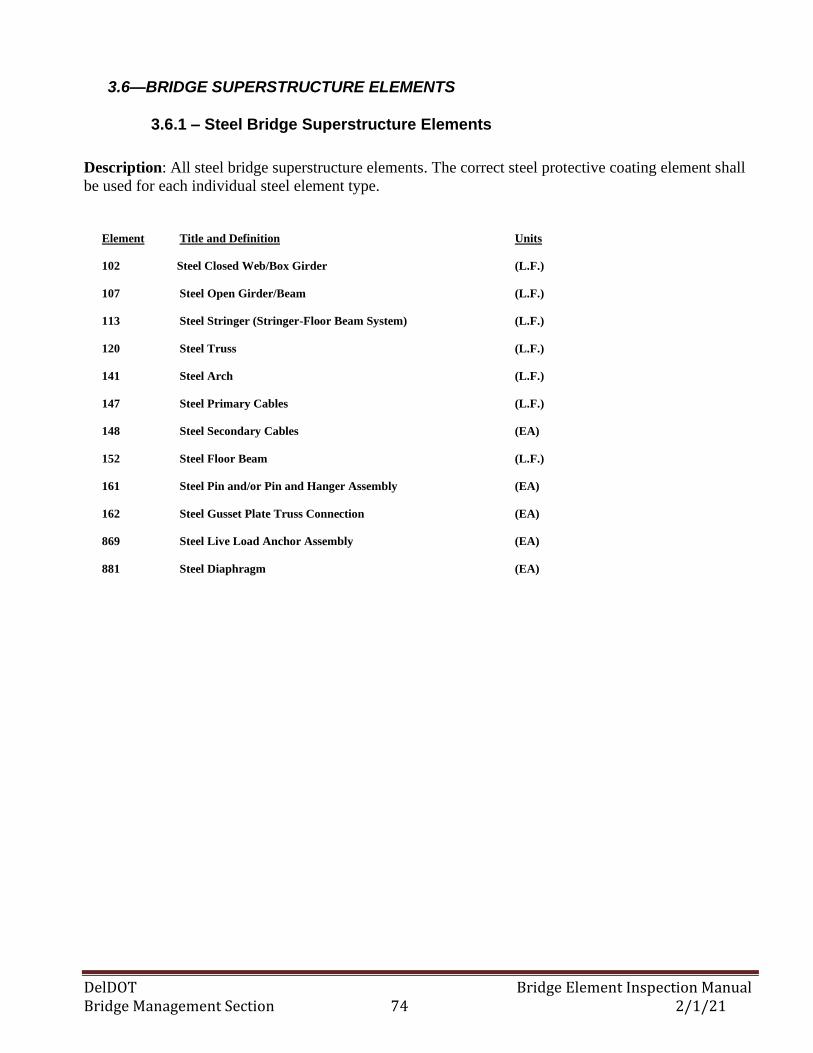
DelDOT Bridge Element Inspection Manual Bridge Management Section 74 2/1/21
3.6—BRIDGE SUPERSTRUCTURE ELEMENTS
3.6.1 – Steel Bridge Superstructure Elements
Description: All steel bridge superstructure elements. The correct steel protective coating element shall
be used for each individual steel element type.
Element Title and Definition Units
102 Steel Closed Web/Box Girder (L.F.)
107 Steel Open Girder/Beam (L.F.)
113 Steel Stringer (Stringer-Floor Beam System) (L.F.)
120 Steel Truss (L.F.)
141 Steel Arch (L.F.)
147 Steel Primary Cables (L.F.)
148 Steel Secondary Cables (EA)
152 Steel Floor Beam (L.F.)
161 Steel Pin and/or Pin and Hanger Assembly (EA)
162 Steel Gusset Plate Truss Connection (EA)
869 Steel Live Load Anchor Assembly (EA)
881 Steel Diaphragm (EA)
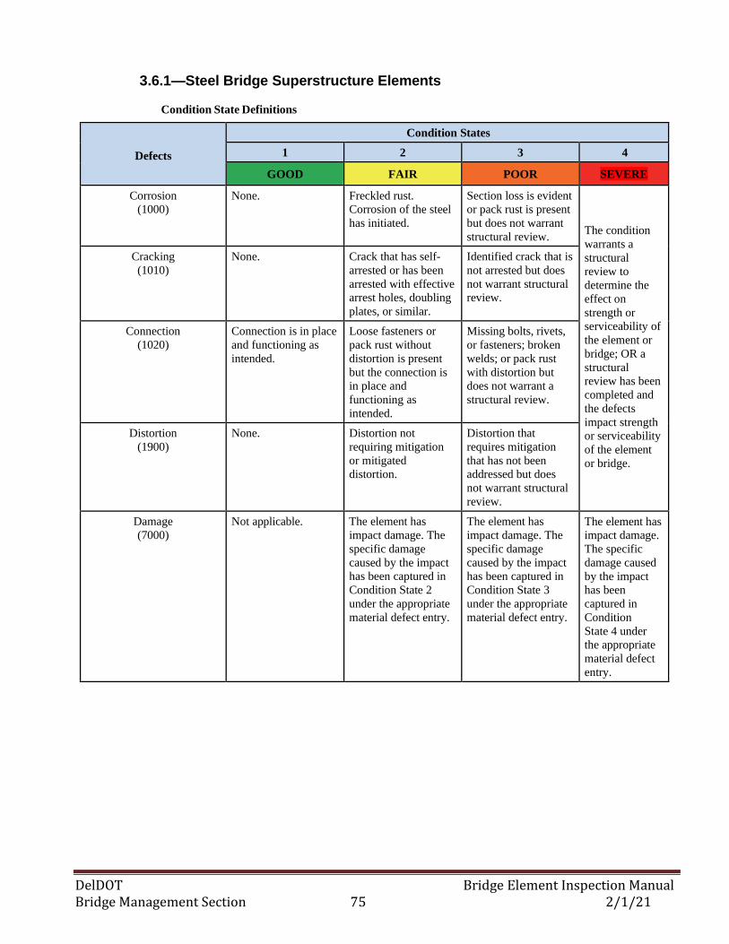
DelDOT Bridge Element Inspection Manual Bridge Management Section 75 2/1/21
3.6.1—Steel Bridge Superstructure Elements
Condition State Definitions
Defects
Condition States
1 2 3 4
GOOD FAIR POOR SEVERE
Corrosion
(1000)
None. Freckled rust.
Corrosion of the steel
has initiated.
Section loss is evident
or pack rust is present
but does not warrant
structural review.
The condition
warrants a
structural
review to
determine the
effect on
strength or
serviceability of
the element or
bridge; OR a
structural
review has been
completed and
the defects
impact strength
or serviceability
of the element
or bridge.
Cracking
(1010)
None. Crack that has self-
arrested or has been
arrested with effective
arrest holes, doubling
plates, or similar.
Identified crack that is
not arrested but does
not warrant structural
review.
Connection
(1020)
Connection is in place
and functioning as
intended.
Loose fasteners or
pack rust without
distortion is present
but the connection is
in place and
functioning as
intended.
Missing bolts, rivets,
or fasteners; broken
welds; or pack rust
with distortion but
does not warrant a
structural review.
Distortion
(1900)
None. Distortion not
requiring mitigation
or mitigated
distortion.
Distortion that
requires mitigation
that has not been
addressed but does
not warrant structural
review.
Damage
(7000)
Not applicable. The element has
impact damage. The
specific damage
caused by the impact
has been captured in
Condition State 2
under the appropriate
material defect entry.
The element has
impact damage. The
specific damage
caused by the impact
has been captured in
Condition State 3
under the appropriate
material defect entry.
The element has
impact damage.
The specific
damage caused
by the impact
has been
captured in
Condition
State 4 under
the appropriate
material defect
entry.
DelDOT Bridge Element Inspection Manual Bridge Management Section 76 2/1/21
3.6—BRIDGE SUPERSTRUCTURE ELEMENTS
3.6.2—Reinforced Concrete Bridge Superstructure Elements
Description: All reinforced concrete bridge elements including National Bridge Elements and
Agency-Developed Elements. Element 521 (Concrete Protective Coating) shall be used for each
individual element type that has a protective coating applied to them. These coatings include
silane/siloxane water proofers, crack sealers such as High Molecular Weight Methacrylate
(HMWM), or any top coat barrier that protects concrete from deterioration and reinforcing steel
from corrosion. Element 520 (Concrete Reinforcing Steel Protective System) shall be used for each
individual element type that has a corrosion protection system installed. Protection systems may
include cathodic protection or addition of anodes to mitigate corrosion.
Element Commentary: Condition evaluation for this element includes the web faces and the top and
bottom flange surfaces. For adjacent box beams element 16 shall be created to identify defects in the top
flange.
Element Title and Definition Units
105 Reinforced Concrete Closed Web/Box Girder (L.F.)
110 Reinforced Concrete Open Girder/Beam (L.F.)
116 Reinforced Concrete Stringer (Stringer-Floor Beam System) (L.F.)
144 Reinforced Concrete Arch (L.F.)
155 Reinforced Concrete Floor Beam (L.F.)
834 Reinforced Concrete Filled Arch (L.F.)
882 Reinforced Concrete Diaphragm (EA)
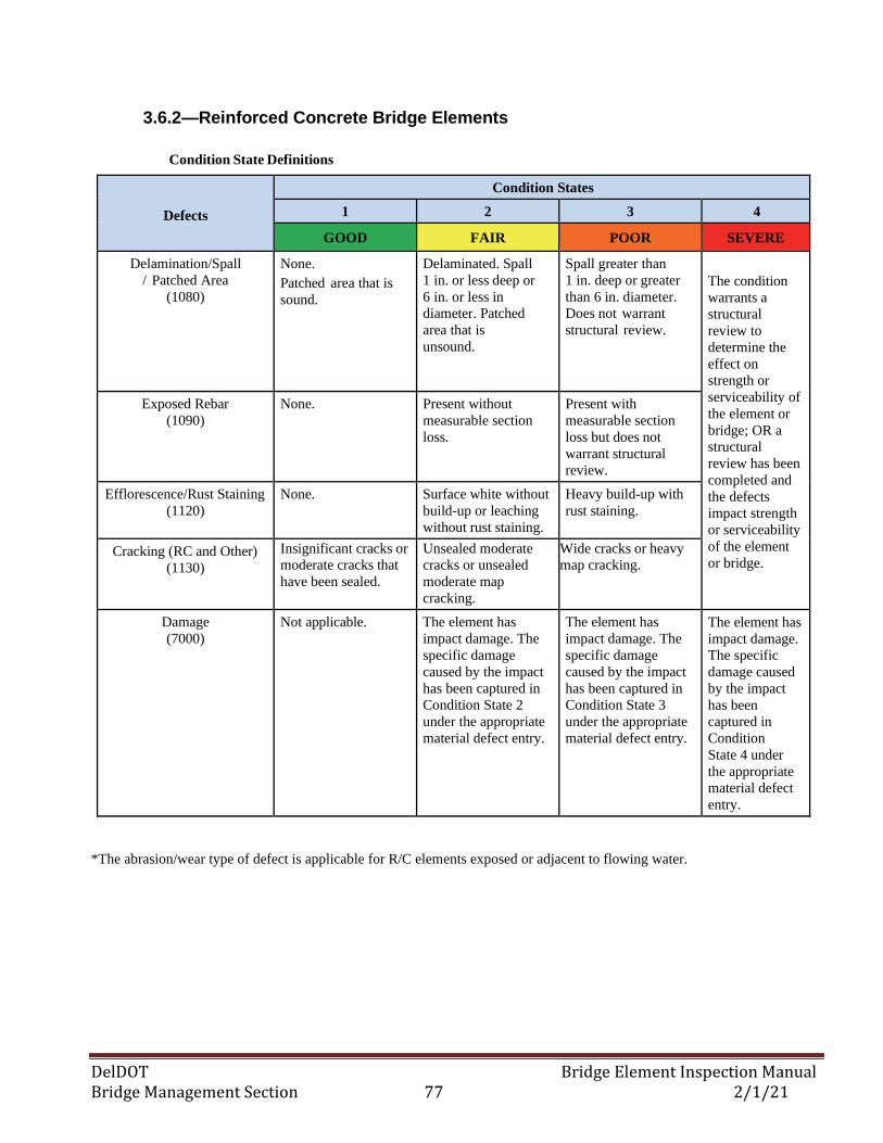
DelDOT Bridge Element Inspection Manual Bridge Management Section 77 2/1/21
3.6.2—Reinforced Concrete Bridge Elements
Condition State Definitions
Defects
Condition States
1 2 3 4
GOOD FAIR POOR SEVERE
Delamination/Spall
/ Patched Area
(1080)
None.
Patched area that is
sound.
Delaminated. Spall
1 in. or less deep or
6 in. or less in
diameter. Patched
area that is
unsound.
Spall greater than
1 in. deep or greater
than 6 in. diameter.
Does not warrant
structural review.
The condition
warrants a
structural
review to
determine the
effect on
strength or
serviceability of
the element or
bridge; OR a
structural
review has been
completed and
the defects
impact strength
or serviceability
of the element
or bridge.
Exposed Rebar
(1090)
None. Present without
measurable section
loss.
Present with
measurable section
loss but does not
warrant structural
review.
Efflorescence/Rust Staining
(1120)
None. Surface white without
build-up or leaching
without rust staining.
Heavy build-up with
rust staining.
Cracking (RC and Other)
(1130)
Insignificant cracks or
moderate cracks that
have been sealed.
Unsealed moderate
cracks or unsealed
moderate map
cracking.
Wide cracks or heavy
map cracking.
Damage
(7000)
Not applicable. The element has
impact damage. The
specific damage
caused by the impact
has been captured in
Condition State 2
under the appropriate
material defect entry.
The element has
impact damage. The
specific damage
caused by the impact
has been captured in
Condition State 3
under the appropriate
material defect entry.
The element has
impact damage.
The specific
damage caused
by the impact
has been
captured in
Condition
State 4 under
the appropriate
material defect
entry.
*The abrasion/wear type of defect is applicable for R/C elements exposed or adjacent to flowing water.
DelDOT Bridge Element Inspection Manual Bridge Management Section 78 2/1/21
3.6—BRIDGE SUPERSTRUCTURE ELEMENTS
3.6.3—Prestressed Concrete Bridge Superstructure Elements
Description: All prestressed concrete bridge elements including National Bridge Elements. Element
521 (Concrete Protective Coating) shall be used for each individual element type that has a
protective coating applied to them. These coatings include silane/siloxane water proofers, crack
sealers such as High Molecular Weight Methacrylate (HMWM), or any top coat barrier that protects
concrete from deterioration and reinforcing steel from corrosion. Element 520 (Concrete
Reinforcing Steel Protective System) shall be used for each individual element type that has a
corrosion protection system installed. Protection systems may include cathodic protection or
addition of anodes to mitigate corrosion.
Element Commentary: Condition evaluation for this element includes the web faces and the top and
bottom flange surfaces if a separate reinforced concrete deck exists on top of the beams. If the bridge
deck is the top flange of the beams (as in elements #15 & 16), then defects in the top, bottom, and side
surfaces of the top flange shall be accounted for in element #15 or 16 and not in the beam element.
Similarly, the NBI Deck Condition Rating shall account for defects in element#15 or 16.
Element Title and Definition Units
104 Prestressed Concrete Closed Web/Box Girder (L.F.)
109 Prestressed Concrete Open Girder/Beam (L.F.)
115 Prestressed Concrete Stringer (Stringer-Floor Beam System) (L.F.)
154 Prestressed Concrete Floor Beam (L.F.)
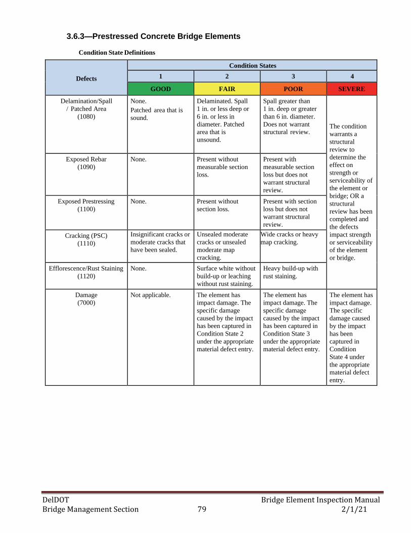
DelDOT Bridge Element Inspection Manual Bridge Management Section 79 2/1/21
3.6.3—Prestressed Concrete Bridge Elements
Condition State Definitions
Defects
Condition States
1 2 3 4
GOOD FAIR POOR SEVERE
Delamination/Spall
/ Patched Area
(1080)
None.
Patched area that is
sound.
Delaminated. Spall
1 in. or less deep or
6 in. or less in
diameter. Patched
area that is
unsound.
Spall greater than
1 in. deep or greater
than 6 in. diameter.
Does not warrant
structural review.
The condition
warrants a
structural
review to
determine the
effect on
strength or
serviceability of
the element or
bridge; OR a
structural
review has been
completed and
the defects
impact strength
or serviceability
of the element
or bridge.
Exposed Rebar
(1090)
None. Present without
measurable section
loss.
Present with
measurable section
loss but does not
warrant structural
review.
Exposed Prestressing
(1100)
None. Present without
section loss.
Present with section
loss but does not
warrant structural
review.
Cracking (PSC)
(1110)
Insignificant cracks or
moderate cracks that
have been sealed.
Unsealed moderate
cracks or unsealed
moderate map
cracking.
Wide cracks or heavy
map cracking.
Efflorescence/Rust Staining
(1120)
None. Surface white without
build-up or leaching
without rust staining.
Heavy build-up with
rust staining.
Damage
(7000)
Not applicable. The element has
impact damage. The
specific damage
caused by the impact
has been captured in
Condition State 2
under the appropriate
material defect entry.
The element has
impact damage. The
specific damage
caused by the impact
has been captured in
Condition State 3
under the appropriate
material defect entry.
The element has
impact damage.
The specific
damage caused
by the impact
has been
captured in
Condition
State 4 under
the appropriate
material defect
entry.
DelDOT Bridge Element Inspection Manual Bridge Management Section 80 2/1/21
3.6—BRIDGE SUPERSTRUCTURE ELEMENTS 3.6.4—Timber Bridge Superstructure Elements
Description: This element defines all timber stringers, floorbeams, truss and arches regardless of
protection system. These elements include solid timbers, glue-lam timbers and nail-lam timbers.
Element Title and Definition Units
111 Timber Open Girder/Beam (L.F.)
117 Timber Stringer (Stringer-Floor Beam System) (L.F.)
135 Timber Truss (L.F.)
146 Timber Arch (L.F.)
156 Timber Floor Beam (L.F.)
883 Timber Diaphragm (EA)
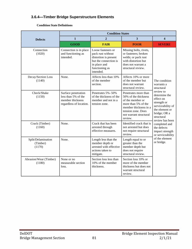
DelDOT Bridge Element Inspection Manual Bridge Management Section 81 2/1/21
3.6.4—Timber Bridge Superstructure Elements
Condition State Definitions
Defects
Condition States
1 2 3 4
GOOD FAIR POOR SEVERE
Connection
(1020)
Connection is in place
and functioning as
intended.
Loose fasteners or
pack rust without
distortion is present
but the connection is
in place and
functioning as
intended.
Missing bolts, rivets,
or fasteners; broken
welds; or pack rust
with distortion but
does not warrant a
structural review.
The condition
warrants a
structural
review to
determine the
effect on
strength or
serviceability of
the element or
bridge; OR a
structural
review has been
completed and
the defects
impact strength
or serviceability
of the element
or bridge.
Decay/Section Loss
(1140)
None. Affects less than 10%
of the member
section.
Affects 10% or more
of the member but
does not warrant
structural review.
Check/Shake
(1150)
Surface penetration
less than 5% of the
member thickness
regardless of location.
Penetrates 5%–50%
of the thickness of the
member and not in a
tension zone.
Penetrates more than
50% of the thickness
of the member or
more than 5% of the
member thickness in a
tension zone. Does
not warrant structural
review.
Crack (Timber)
(1160)
None. Crack that has been
arrested through
effective measures.
Identified crack that is
not arrested but does
not require structural
review.
Split/Delamination
(Timber)
(1170)
None. Length less than the
member depth or
arrested with effective
actions taken to
mitigate.
Length equal to or
greater than the
member depth but
does not require
structural review.
Abrasion/Wear (Timber)
(1180)
None or no
measurable section
loss.
Section loss less than
10% of the member
thickness.
Section loss 10% or
more of the member
thickness but does not
warrant structural
review.
DelDOT Bridge Element Inspection Manual Bridge Management Section 82 2/1/21
3.6—BRIDGE SUPERSTRUCTURE ELEMENTS 3.6.5—Masonry Bridge Superstructure Element
Description: Masonry or stacked stone arches regardless of protective system.
Element Commentary: Observed distress in arch spandrel walls shall be reported as the projected length
along the arch length. For filled arches, the arch quantity shall be measured from spring line to spring
line. The length below the spring line is considered substructure.
Element Title and Definition Units
145 Masonry Arch (L.F.)
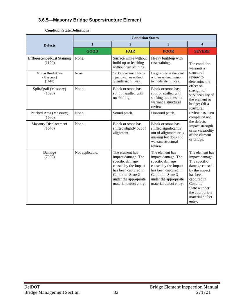
DelDOT Bridge Element Inspection Manual Bridge Management Section 83 2/1/21
3.6.5—Masonry Bridge Superstructure Element
Condition State Definitions
Defects
Condition States
1 2 3 4
GOOD FAIR POOR SEVERE
Efflorescence/Rust Staining
(1120)
None. Surface white without
build-up or leaching
without rust staining.
Heavy build-up with
rust staining.
The condition
warrants a
structural
review to
determine the
effect on
strength or
serviceability of
the element or
bridge; OR a
structural
review has been
completed and
the defects
impact strength
or serviceability
of the element
or bridge.
Mortar Breakdown
(Masonry) (1610)
None. Cracking or small voids
in joint with or without
insignificant fill loss.
Large voids in the joint
with or without minor
to moderate fill loss.
Split/Spall (Masonry)
(1620)
None. Block or stone has
split or spalled with
no shifting.
Block or stone has
split or spalled with
shifting but does not
warrant a structural
review.
Patched Area (Masonry)
(1630)
None. Sound patch. Unsound patch.
Masonry Displacement
(1640)
None. Block or stone has
shifted slightly out of
alignment.
Block or stone has
shifted significantly
out of alignment or is
missing but does not
warrant structural
review.
Damage
(7000)
Not applicable. The element has
impact damage. The
specific damage
caused by the impact
has been captured in
Condition State 2
under the appropriate
material defect entry.
The element has
impact damage. The
specific damage
caused by the impact
has been captured in
Condition State 3
under the appropriate
material defect entry.
The element has
impact damage.
The specific
damage caused
by the impact
has been
captured in
Condition
State 4 under
the appropriate
material defect
entry.
DelDOT Bridge Element Inspection Manual Bridge Management Section 84 2/1/21
3.6—BRIDGE SUPERSTRUCTURE ELEMENTS 3.6.6—Other Bridge Superstructure Elements
Description: All other material girders regardless of protection system.
Element Commentary: The other material open girder is intended for open girders constructed of
composite materials, or other materials that cannot be classified using any other defined open girder
element.
Element Title and Definition Units
106 Other Closed Web/Box Girder (L.F.)
112 Other Open Girder/Beam (L.F.)
118 Other Stringer (L.F.)
136 Other Truss (L.F.)
142 Other Arch (L.F.)
149 Other Secondary Cables (EA)
157 Other Floor Beam (L.F.)
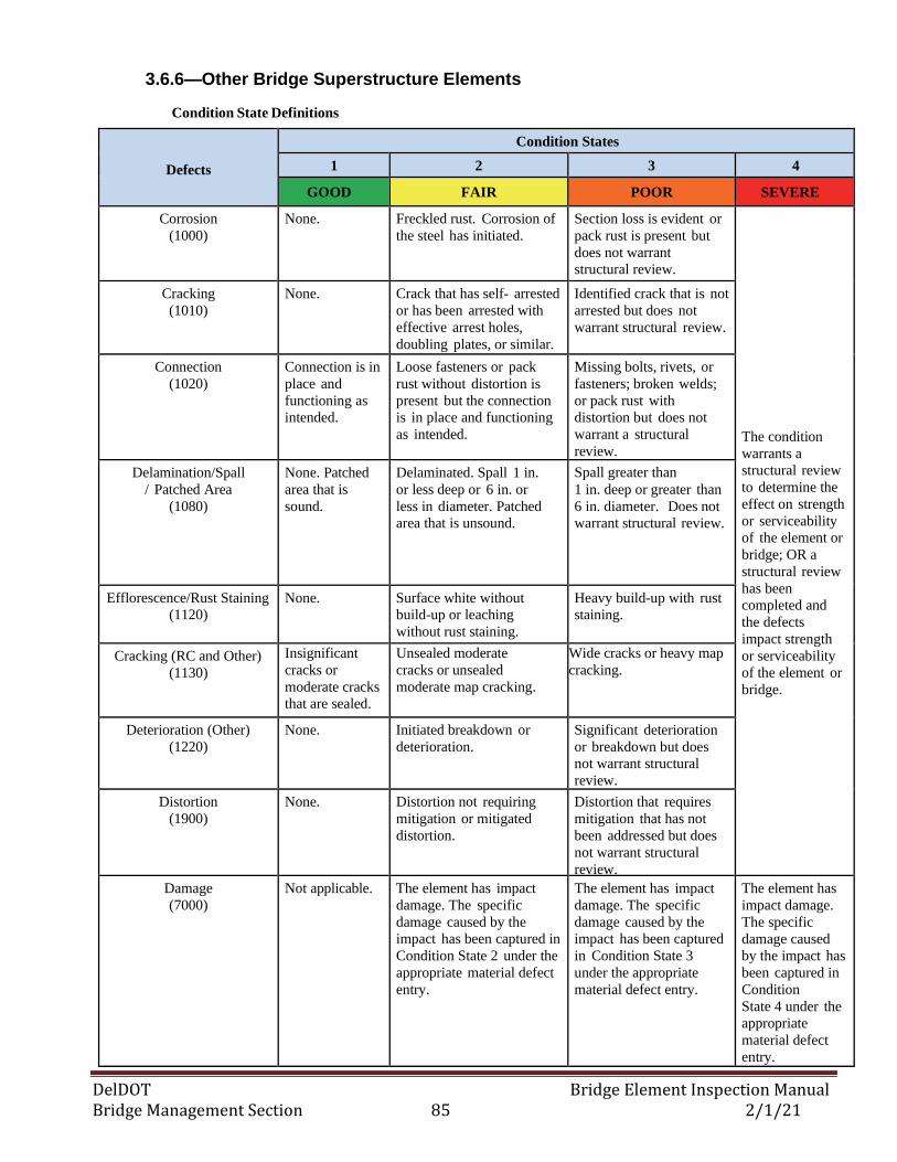
DelDOT Bridge Element Inspection Manual Bridge Management Section 85 2/1/21
3.6.6—Other Bridge Superstructure Elements
Condition State Definitions
Defects
Condition States
1 2 3 4
GOOD FAIR POOR SEVERE
Corrosion
(1000)
None. Freckled rust. Corrosion of
the steel has initiated.
Section loss is evident or
pack rust is present but
does not warrant
structural review.
The condition
warrants a
structural review
to determine the
effect on strength
or serviceability
of the element or
bridge; OR a
structural review
has been
completed and
the defects
impact strength
or serviceability
of the element or
bridge.
Cracking
(1010)
None. Crack that has self- arrested
or has been arrested with
effective arrest holes,
doubling plates, or similar.
Identified crack that is not
arrested but does not
warrant structural review.
Connection
(1020)
Connection is in
place and
functioning as
intended.
Loose fasteners or pack
rust without distortion is
present but the connection
is in place and functioning
as intended.
Missing bolts, rivets, or
fasteners; broken welds;
or pack rust with
distortion but does not
warrant a structural
review.
Delamination/Spall
/ Patched Area
(1080)
None. Patched
area that is
sound.
Delaminated. Spall 1 in.
or less deep or 6 in. or
less in diameter. Patched
area that is unsound.
Spall greater than
1 in. deep or greater than
6 in. diameter. Does not
warrant structural review.
Efflorescence/Rust Staining
(1120)
None. Surface white without
build-up or leaching
without rust staining.
Heavy build-up with rust
staining.
Cracking (RC and Other)
(1130)
Insignificant
cracks or
moderate cracks
that are sealed.
Unsealed moderate
cracks or unsealed
moderate map cracking.
Wide cracks or heavy map
cracking.
Deterioration (Other)
(1220)
None. Initiated breakdown or
deterioration.
Significant deterioration
or breakdown but does
not warrant structural
review.
Distortion
(1900)
None. Distortion not requiring
mitigation or mitigated
distortion.
Distortion that requires
mitigation that has not
been addressed but does
not warrant structural
review.
Damage
(7000)
Not applicable. The element has impact
damage. The specific
damage caused by the
impact has been captured in
Condition State 2 under the
appropriate material defect
entry.
The element has impact
damage. The specific
damage caused by the
impact has been captured
in Condition State 3
under the appropriate
material defect entry.
The element has
impact damage.
The specific
damage caused
by the impact has
been captured in
Condition
State 4 under the
appropriate
material defect
entry.
DelDOT Bridge Element Inspection Manual Bridge Management Section 86 2/1/21
3.7— BRIDGE BEARING ELEMENTS
3.7.1 – Bridge Bearings w/ an Elastomer
Description: Those bridge bearings including elastomeric and pot type of bearings. Elastomeric
bearings may or may not have fabric or metal reinforcement. Pot bearings are high load bearings with a
confined elastomer that may be fixed against horizontal movement, guided to allow sliding in one
direction or floating to allow sliding in any direction.
Element Title and Definition Units
310 Elastomeric Bearing (EA)
314 Pot Bearing (EA)
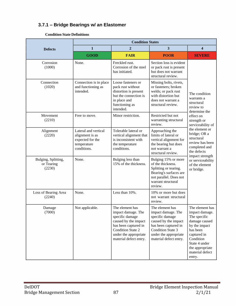
DelDOT Bridge Element Inspection Manual Bridge Management Section 87 2/1/21
3.7.1 – Bridge Bearings w/ an Elastomer
Condition State Definitions
Defects
Condition States
1 2 3 4
GOOD FAIR POOR SEVERE
Corrosion
(1000)
None. Freckled rust.
Corrosion of the steel
has initiated.
Section loss is evident
or pack rust is present
but does not warrant
structural review.
The condition
warrants a
structural
review to
determine the
effect on
strength or
serviceability of
the element or
bridge; OR a
structural
review has been
completed and
the defects
impact strength
or serviceability
of the element
or bridge.
Connection
(1020)
Connection is in place
and functioning as
intended.
Loose fasteners or
pack rust without
distortion is present
but the connection is
in place and
functioning as
intended.
Missing bolts, rivets,
or fasteners; broken
welds; or pack rust
with distortion but
does not warrant a
structural review.
Movement
(2210)
Free to move. Minor restriction. Restricted but not
warranting structural
review.
Alignment
(2220)
Lateral and vertical
alignment is as
expected for the
temperature
conditions.
Tolerable lateral or
vertical alignment that
is inconsistent with
the temperature
conditions.
Approaching the
limits of lateral or
vertical alignment for
the bearing but does
not warrant a
structural review.
Bulging, Splitting,
or Tearing (2230)
None. Bulging less than
15% of the thickness.
Bulging 15% or more
of the thickness.
Splitting or tearing.
Bearing's surfaces are
not parallel. Does not
warrant structural
review.
Loss of Bearing Area
(2240)
None. Less than 10%. 10% or more but does
not warrant structural
review.
Damage
(7000)
Not applicable. The element has
impact damage. The
specific damage
caused by the impact
has been captured in
Condition State 2
under the appropriate
material defect entry.
The element has
impact damage. The
specific damage
caused by the impact
has been captured in
Condition State 3
under the appropriate
material defect entry.
The element has
impact damage.
The specific
damage caused
by the impact
has been
captured in
Condition
State 4 under
the appropriate
material defect
entry.
DelDOT Bridge Element Inspection Manual Bridge Management Section 88 2/1/21
3.7— BRIDGE BEARING ELEMENTS
3.7.2 – Bridge Bearings w/o an Elastomer
Description: Includes movable, enclosed/concealed, fixed & disk bearings. Movable bearings provide
for both rotational and longitudinal movement by means of a roller, rocker or sliding mechanisms.
Fixed bearings only provide for rotation (no longitudinal movement). Disk bearings are a high load
bearing with a hard plastic disk that may be fixed against horizontal movement, guided to allow
movement in one direction or floating to allow sliding in any direction.
Element Title and Definition Units
311 Movable Bearing (EA)
312 Enclosed/Concealed Bearing (EA)
313 Fixed Bearing (EA)
315 Disk Bearing (EA)
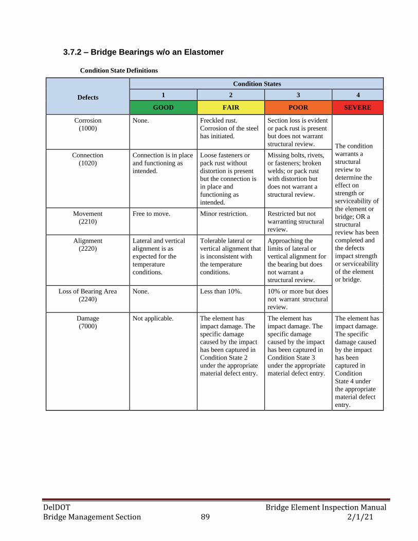
DelDOT Bridge Element Inspection Manual Bridge Management Section 89 2/1/21
3.7.2 – Bridge Bearings w/o an Elastomer
Condition State Definitions
Defects
Condition States
1 2 3 4
GOOD FAIR POOR SEVERE
Corrosion
(1000)
None. Freckled rust.
Corrosion of the steel
has initiated.
Section loss is evident
or pack rust is present
but does not warrant
structural review.
The condition
warrants a
structural
review to
determine the
effect on
strength or
serviceability of
the element or
bridge; OR a
structural
review has been
completed and
the defects
impact strength
or serviceability
of the element
or bridge.
Connection
(1020)
Connection is in place
and functioning as
intended.
Loose fasteners or
pack rust without
distortion is present
but the connection is
in place and
functioning as
intended.
Missing bolts, rivets,
or fasteners; broken
welds; or pack rust
with distortion but
does not warrant a
structural review.
Movement
(2210)
Free to move. Minor restriction. Restricted but not
warranting structural
review.
Alignment
(2220)
Lateral and vertical
alignment is as
expected for the
temperature
conditions.
Tolerable lateral or
vertical alignment that
is inconsistent with
the temperature
conditions.
Approaching the
limits of lateral or
vertical alignment for
the bearing but does
not warrant a
structural review.
Loss of Bearing Area
(2240)
None. Less than 10%. 10% or more but does
not warrant structural
review.
Damage
(7000)
Not applicable. The element has
impact damage. The
specific damage
caused by the impact
has been captured in
Condition State 2
under the appropriate
material defect entry.
The element has
impact damage. The
specific damage
caused by the impact
has been captured in
Condition State 3
under the appropriate
material defect entry.
The element has
impact damage.
The specific
damage caused
by the impact
has been
captured in
Condition
State 4 under
the appropriate
material defect
entry.
DelDOT Bridge Element Inspection Manual Bridge Management Section 90 2/1/21
3.7— BRIDGE BEARING ELEMENTS
3.7.3 – Other Bridge Bearing
Description: All other material bridge bearings regardless of translation or rotation constraints.
Element Title and Definition Units
316 Other Bearing (EA)
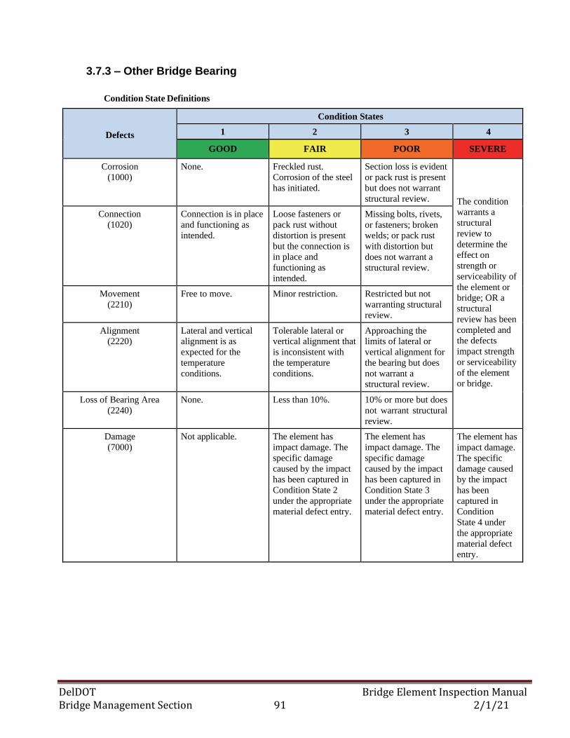
DelDOT Bridge Element Inspection Manual Bridge Management Section 91 2/1/21
3.7.3 – Other Bridge Bearing
Condition State Definitions
Defects
Condition States
1 2 3 4
GOOD FAIR POOR SEVERE
Corrosion
(1000)
None. Freckled rust.
Corrosion of the steel
has initiated.
Section loss is evident
or pack rust is present
but does not warrant
structural review.
The condition
warrants a
structural
review to
determine the
effect on
strength or
serviceability of
the element or
bridge; OR a
structural
review has been
completed and
the defects
impact strength
or serviceability
of the element
or bridge.
Connection
(1020)
Connection is in place
and functioning as
intended.
Loose fasteners or
pack rust without
distortion is present
but the connection is
in place and
functioning as
intended.
Missing bolts, rivets,
or fasteners; broken
welds; or pack rust
with distortion but
does not warrant a
structural review.
Movement
(2210)
Free to move. Minor restriction. Restricted but not
warranting structural
review.
Alignment
(2220)
Lateral and vertical
alignment is as
expected for the
temperature
conditions.
Tolerable lateral or
vertical alignment that
is inconsistent with
the temperature
conditions.
Approaching the
limits of lateral or
vertical alignment for
the bearing but does
not warrant a
structural review.
Loss of Bearing Area
(2240)
None. Less than 10%. 10% or more but does
not warrant structural
review.
Damage
(7000)
Not applicable. The element has
impact damage. The
specific damage
caused by the impact
has been captured in
Condition State 2
under the appropriate
material defect entry.
The element has
impact damage. The
specific damage
caused by the impact
has been captured in
Condition State 3
under the appropriate
material defect entry.
The element has
impact damage.
The specific
damage caused
by the impact
has been
captured in
Condition
State 4 under
the appropriate
material defect
entry.
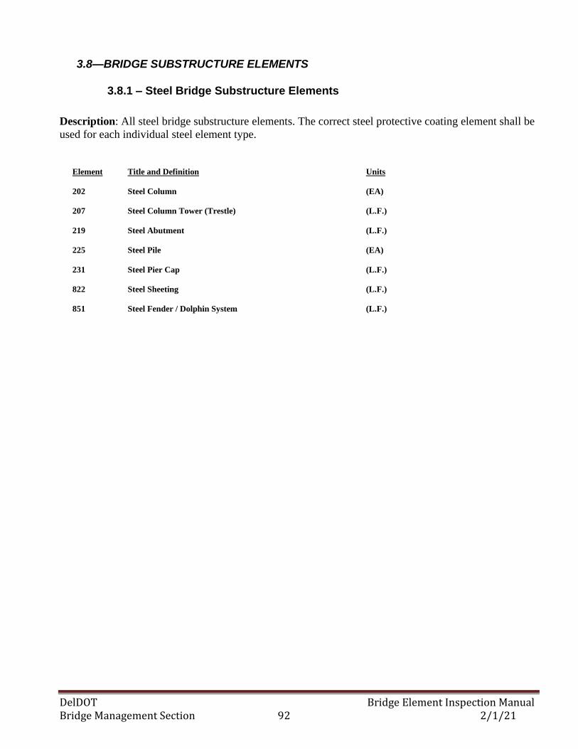
DelDOT Bridge Element Inspection Manual Bridge Management Section 92 2/1/21
3.8—BRIDGE SUBSTRUCTURE ELEMENTS
3.8.1 – Steel Bridge Substructure Elements
Description: All steel bridge substructure elements. The correct steel protective coating element shall be
used for each individual steel element type.
Element Title and Definition Units
202 Steel Column (EA)
207 Steel Column Tower (Trestle) (L.F.)
219 Steel Abutment (L.F.)
225 Steel Pile (EA)
231 Steel Pier Cap (L.F.)
822 Steel Sheeting (L.F.)
851 Steel Fender / Dolphin System (L.F.)
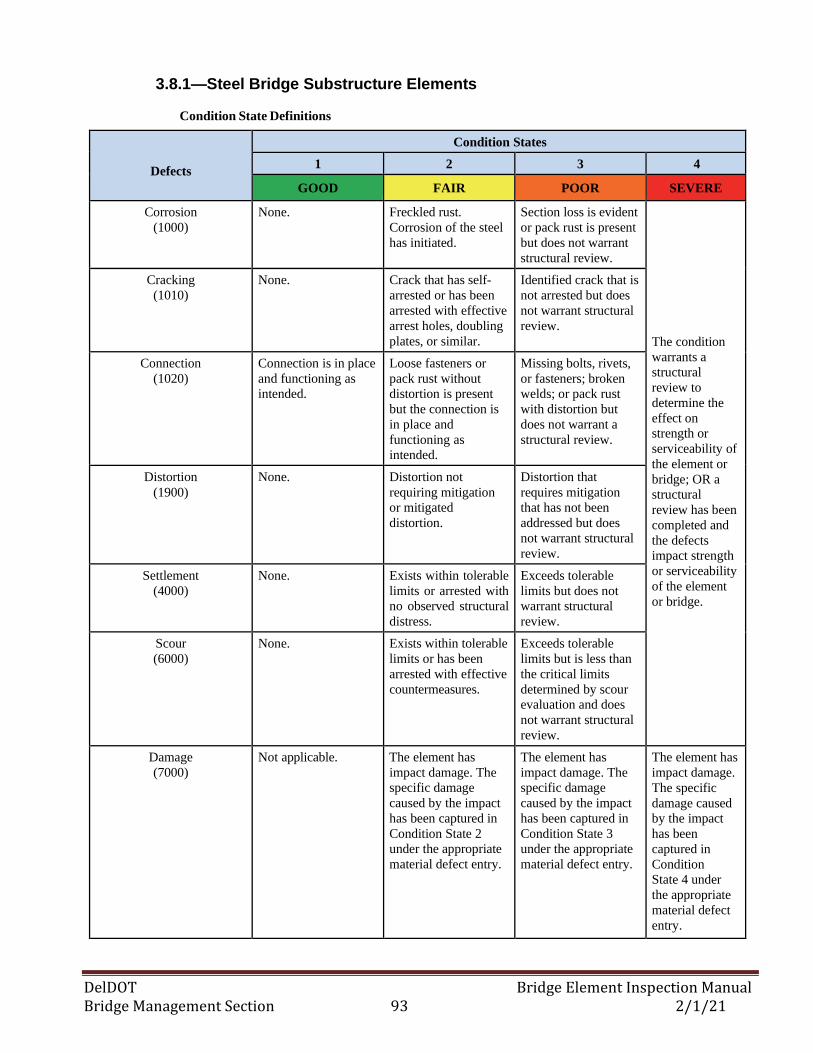
DelDOT Bridge Element Inspection Manual Bridge Management Section 93 2/1/21
3.8.1—Steel Bridge Substructure Elements
Condition State Definitions
Defects
Condition States
1 2 3 4
GOOD FAIR POOR SEVERE
Corrosion
(1000)
None. Freckled rust.
Corrosion of the steel
has initiated.
Section loss is evident
or pack rust is present
but does not warrant
structural review.
The condition
warrants a
structural
review to
determine the
effect on
strength or
serviceability of
the element or
bridge; OR a
structural
review has been
completed and
the defects
impact strength
or serviceability
of the element
or bridge.
Cracking
(1010)
None. Crack that has self-
arrested or has been
arrested with effective
arrest holes, doubling
plates, or similar.
Identified crack that is
not arrested but does
not warrant structural
review.
Connection
(1020)
Connection is in place
and functioning as
intended.
Loose fasteners or
pack rust without
distortion is present
but the connection is
in place and
functioning as
intended.
Missing bolts, rivets,
or fasteners; broken
welds; or pack rust
with distortion but
does not warrant a
structural review.
Distortion
(1900)
None. Distortion not
requiring mitigation
or mitigated
distortion.
Distortion that
requires mitigation
that has not been
addressed but does
not warrant structural
review.
Settlement
(4000)
None. Exists within tolerable
limits or arrested with
no observed structural
distress.
Exceeds tolerable
limits but does not
warrant structural
review.
Scour
(6000)
None. Exists within tolerable
limits or has been
arrested with effective
countermeasures.
Exceeds tolerable
limits but is less than
the critical limits
determined by scour
evaluation and does
not warrant structural
review.
Damage
(7000)
Not applicable. The element has
impact damage. The
specific damage
caused by the impact
has been captured in
Condition State 2
under the appropriate
material defect entry.
The element has
impact damage. The
specific damage
caused by the impact
has been captured in
Condition State 3
under the appropriate
material defect entry.
The element has
impact damage.
The specific
damage caused
by the impact
has been
captured in
Condition
State 4 under
the appropriate
material defect
entry.
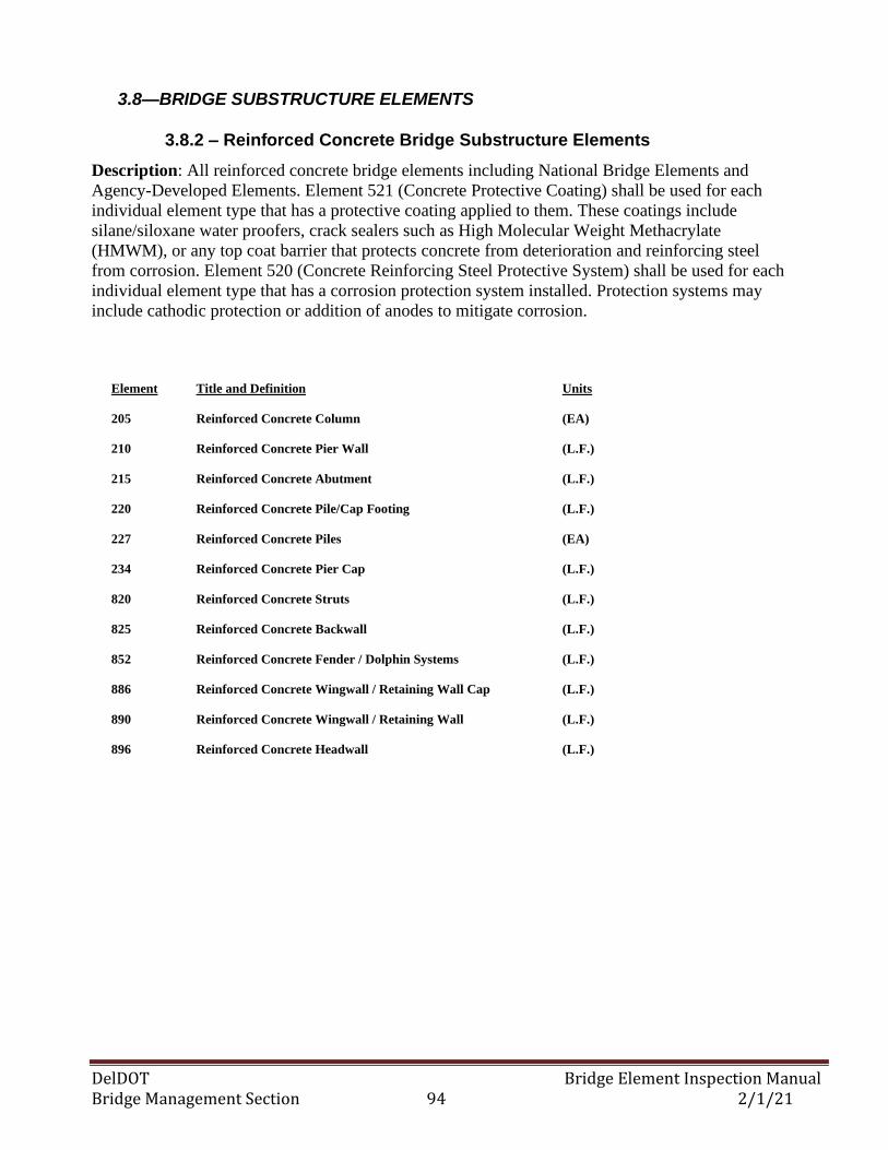
DelDOT Bridge Element Inspection Manual Bridge Management Section 94 2/1/21
3.8—BRIDGE SUBSTRUCTURE ELEMENTS
3.8.2 – Reinforced Concrete Bridge Substructure Elements
Description: All reinforced concrete bridge elements including National Bridge Elements and
Agency-Developed Elements. Element 521 (Concrete Protective Coating) shall be used for each
individual element type that has a protective coating applied to them. These coatings include
silane/siloxane water proofers, crack sealers such as High Molecular Weight Methacrylate
(HMWM), or any top coat barrier that protects concrete from deterioration and reinforcing steel
from corrosion. Element 520 (Concrete Reinforcing Steel Protective System) shall be used for each
individual element type that has a corrosion protection system installed. Protection systems may
include cathodic protection or addition of anodes to mitigate corrosion.
Element Title and Definition Units
205 Reinforced Concrete Column (EA)
210 Reinforced Concrete Pier Wall (L.F.)
215 Reinforced Concrete Abutment (L.F.)
220 Reinforced Concrete Pile/Cap Footing (L.F.)
227 Reinforced Concrete Piles (EA)
234 Reinforced Concrete Pier Cap (L.F.)
820 Reinforced Concrete Struts (L.F.)
825 Reinforced Concrete Backwall (L.F.)
852 Reinforced Concrete Fender / Dolphin Systems (L.F.)
886 Reinforced Concrete Wingwall / Retaining Wall Cap (L.F.)
890 Reinforced Concrete Wingwall / Retaining Wall (L.F.)
896 Reinforced Concrete Headwall (L.F.)
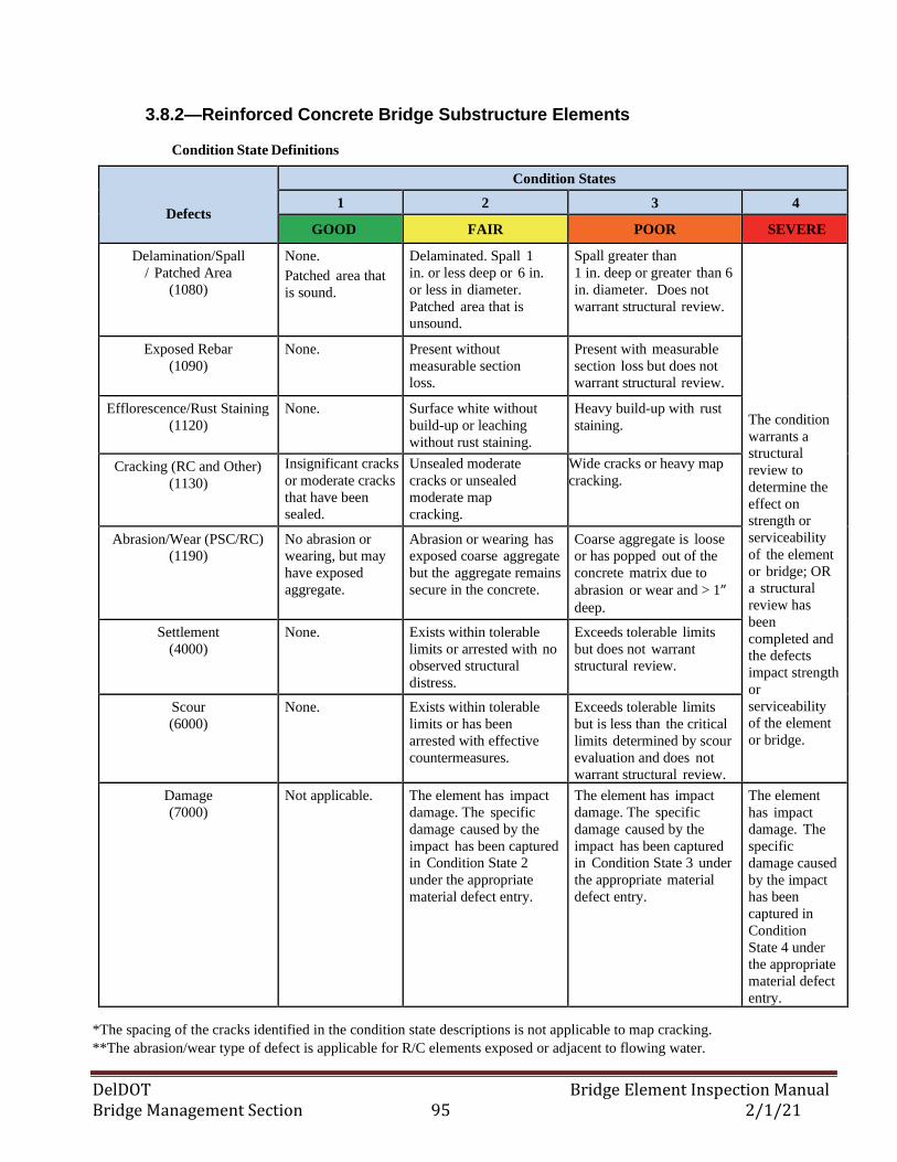
DelDOT Bridge Element Inspection Manual Bridge Management Section 95 2/1/21
3.8.2—Reinforced Concrete Bridge Substructure Elements
Condition State Definitions
Defects
Condition States
1 2 3 4
GOOD FAIR POOR SEVERE
Delamination/Spall
/ Patched Area
(1080)
None.
Patched area that
is sound.
Delaminated. Spall 1
in. or less deep or 6 in.
or less in diameter.
Patched area that is
unsound.
Spall greater than
1 in. deep or greater than 6
in. diameter. Does not
warrant structural review.
The condition
warrants a
structural
review to
determine the
effect on
strength or
serviceability
of the element
or bridge; OR
a structural
review has
been
completed and
the defects
impact strength
or
serviceability
of the element
or bridge.
Exposed Rebar
(1090)
None. Present without
measurable section
loss.
Present with measurable
section loss but does not
warrant structural review.
Efflorescence/Rust Staining
(1120)
None. Surface white without
build-up or leaching
without rust staining.
Heavy build-up with rust
staining.
Cracking (RC and Other)
(1130)
Insignificant cracks
or moderate cracks
that have been
sealed.
Unsealed moderate
cracks or unsealed
moderate map
cracking.
Wide cracks or heavy map
cracking.
Abrasion/Wear (PSC/RC)
(1190)
No abrasion or
wearing, but may
have exposed
aggregate.
Abrasion or wearing has
exposed coarse aggregate
but the aggregate remains
secure in the concrete.
Coarse aggregate is loose
or has popped out of the
concrete matrix due to
abrasion or wear and > 1” deep.
Settlement
(4000)
None. Exists within tolerable
limits or arrested with no
observed structural
distress.
Exceeds tolerable limits
but does not warrant
structural review.
Scour
(6000)
None. Exists within tolerable
limits or has been
arrested with effective
countermeasures.
Exceeds tolerable limits
but is less than the critical
limits determined by scour
evaluation and does not
warrant structural review.
Damage
(7000)
Not applicable. The element has impact
damage. The specific
damage caused by the
impact has been captured
in Condition State 2
under the appropriate
material defect entry.
The element has impact
damage. The specific
damage caused by the
impact has been captured
in Condition State 3 under
the appropriate material
defect entry.
The element
has impact
damage. The
specific
damage caused
by the impact
has been
captured in
Condition
State 4 under
the appropriate
material defect
entry.
*The spacing of the cracks identified in the condition state descriptions is not applicable to map cracking.
**The abrasion/wear type of defect is applicable for R/C elements exposed or adjacent to flowing water.
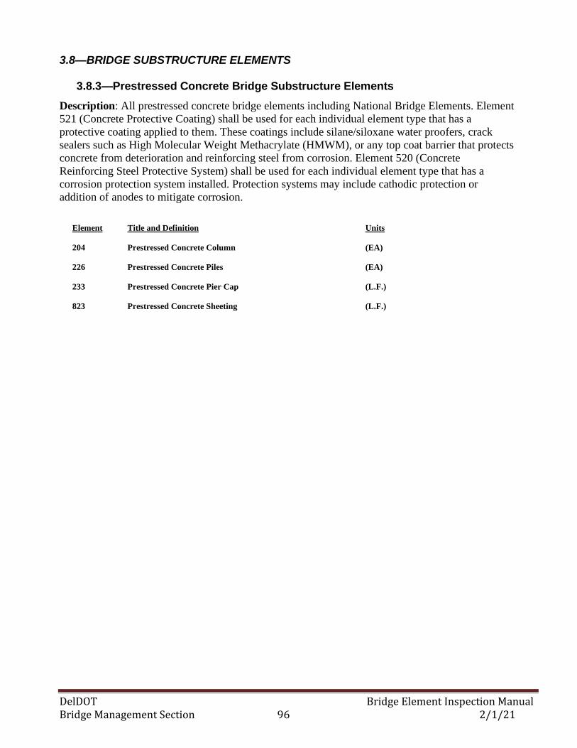
DelDOT Bridge Element Inspection Manual Bridge Management Section 96 2/1/21
3.8—BRIDGE SUBSTRUCTURE ELEMENTS
3.8.3—Prestressed Concrete Bridge Substructure Elements
Description: All prestressed concrete bridge elements including National Bridge Elements. Element
521 (Concrete Protective Coating) shall be used for each individual element type that has a
protective coating applied to them. These coatings include silane/siloxane water proofers, crack
sealers such as High Molecular Weight Methacrylate (HMWM), or any top coat barrier that protects
concrete from deterioration and reinforcing steel from corrosion. Element 520 (Concrete
Reinforcing Steel Protective System) shall be used for each individual element type that has a
corrosion protection system installed. Protection systems may include cathodic protection or
addition of anodes to mitigate corrosion.
Element Title and Definition Units
204 Prestressed Concrete Column (EA)
226 Prestressed Concrete Piles (EA)
233 Prestressed Concrete Pier Cap (L.F.)
823 Prestressed Concrete Sheeting (L.F.)
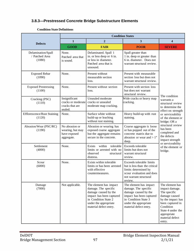
DelDOT Bridge Element Inspection Manual Bridge Management Section 97 2/1/21
3.8.3—Prestressed Concrete Bridge Substructure Elements
Condition State Definitions
Defects
Condition States
1 2 3 4
GOOD FAIR POOR SEVERE
Delamination/Spall
/ Patched Area
(1080)
None.
Patched area that
is sound.
Delaminated. Spall 1
in. or less deep or 6 in.
or less in diameter.
Patched area that is
unsound.
Spall greater than
1 in. deep or greater than
6 in. diameter. Does not
warrant structural review.
The condition
warrants a
structural review
to determine the
effect on strength
or serviceability
of the element or
bridge; OR a
structural review
has been
completed and
the defects
impact strength
or serviceability
of the element or
bridge.
Exposed Rebar
(1090)
None. Present without
measurable section
loss.
Present with measurable
section loss but does not
warrant structural review.
Exposed Prestressing
(1100)
None. Present without section
loss.
Present with section loss
but does not warrant
structural review.
Cracking (PSC)
(1110)
Insignificant
cracks or moderate
cracks that are
sealed.
Unsealed moderate
cracks or unsealed
moderate map cracking.
Wide cracks or heavy map
cracking.
Efflorescence/Rust Staining
(1120)
None. Surface white without
build-up or leaching
without rust staining.
Heavy build-up with rust
staining.
Abrasion/Wear (PSC/RC)
(1190)
No abrasion or
wearing, but may
have exposed
aggregate.
Abrasion or wearing has
exposed coarse aggregate
but the aggregate remains
secure in the concrete.
Coarse aggregate is loose
or has popped out of the
concrete matrix due to
abrasion or wear and > 1” deep.
Settlement
(4000)
None. Exists within tolerable
limits or arrested with no
observed structural
distress.
Exceeds tolerable
limits but does not
warrant structural
review.
Scour
(6000)
None. Exists within tolerable
limits or has been arrested
with effective
countermeasures.
Exceeds tolerable limits
but is less than the critical
limits determined by
scour evaluation and does
not warrant structural
review.
Damage
(7000)
Not applicable. The element has impact
damage. The specific
damage caused by the
impact has been captured
in Condition State 2
under the appropriate
material defect entry.
The element has impact
damage. The specific
damage caused by the
impact has been captured
in Condition State 3
under the appropriate
material defect entry.
The element has
impact damage.
The specific
damage caused
by the impact has
been captured in
Condition
State 4 under the
appropriate
material defect
entry.
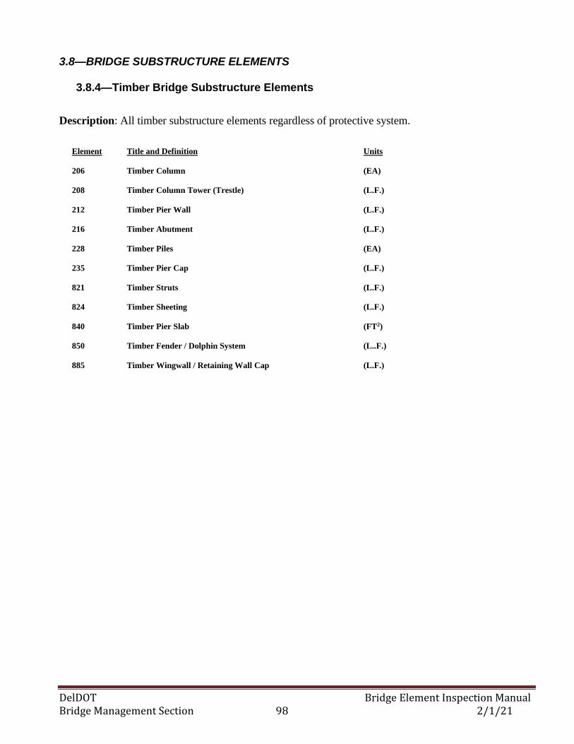
DelDOT Bridge Element Inspection Manual Bridge Management Section 98 2/1/21
3.8—BRIDGE SUBSTRUCTURE ELEMENTS
3.8.4—Timber Bridge Substructure Elements
Description: All timber substructure elements regardless of protective system.
Element Title and Definition Units
206 Timber Column (EA)
208 Timber Column Tower (Trestle) (L.F.)
212 Timber Pier Wall (L.F.)
216 Timber Abutment (L.F.)
228 Timber Piles (EA)
235 Timber Pier Cap (L.F.)
821 Timber Struts (L.F.)
824 Timber Sheeting (L.F.)
840 Timber Pier Slab (FT2)
850 Timber Fender / Dolphin System (L..F.)
885 Timber Wingwall / Retaining Wall Cap (L.F.)
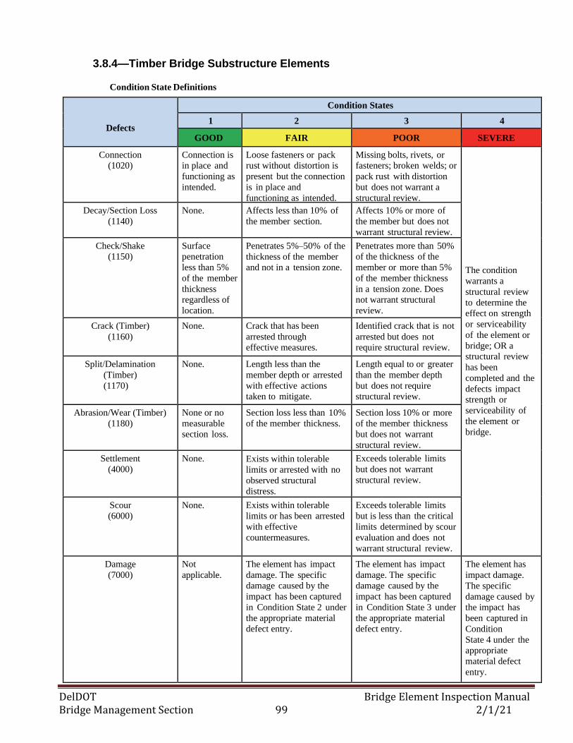
DelDOT Bridge Element Inspection Manual Bridge Management Section 99 2/1/21
3.8.4—Timber Bridge Substructure Elements
Condition State Definitions
Defects
Condition States
1 2 3 4
GOOD FAIR POOR SEVERE
Connection
(1020)
Connection is
in place and
functioning as
intended.
Loose fasteners or pack
rust without distortion is
present but the connection
is in place and
functioning as intended.
Missing bolts, rivets, or
fasteners; broken welds; or
pack rust with distortion
but does not warrant a
structural review.
The condition
warrants a
structural review
to determine the
effect on strength
or serviceability
of the element or
bridge; OR a
structural review
has been
completed and the
defects impact
strength or
serviceability of
the element or
bridge.
Decay/Section Loss
(1140)
None. Affects less than 10% of
the member section.
Affects 10% or more of
the member but does not
warrant structural review.
Check/Shake
(1150)
Surface
penetration
less than 5%
of the member
thickness
regardless of
location.
Penetrates 5%–50% of the
thickness of the member
and not in a tension zone.
Penetrates more than 50%
of the thickness of the
member or more than 5%
of the member thickness
in a tension zone. Does
not warrant structural
review.
Crack (Timber)
(1160)
None. Crack that has been
arrested through
effective measures.
Identified crack that is not
arrested but does not
require structural review.
Split/Delamination
(Timber)
(1170)
None. Length less than the
member depth or arrested
with effective actions
taken to mitigate.
Length equal to or greater
than the member depth
but does not require
structural review.
Abrasion/Wear (Timber)
(1180)
None or no
measurable
section loss.
Section loss less than 10%
of the member thickness.
Section loss 10% or more
of the member thickness
but does not warrant
structural review.
Settlement
(4000)
None. Exists within tolerable
limits or arrested with no
observed structural
distress.
Exceeds tolerable limits
but does not warrant
structural review.
Scour
(6000)
None. Exists within tolerable
limits or has been arrested
with effective
countermeasures.
Exceeds tolerable limits
but is less than the critical
limits determined by scour
evaluation and does not
warrant structural review.
Damage
(7000)
Not
applicable.
The element has impact
damage. The specific
damage caused by the
impact has been captured
in Condition State 2 under
the appropriate material
defect entry.
The element has impact
damage. The specific
damage caused by the
impact has been captured
in Condition State 3 under
the appropriate material
defect entry.
The element has
impact damage.
The specific
damage caused by
the impact has
been captured in
Condition
State 4 under the
appropriate
material defect
entry.
DelDOT Bridge Element Inspection Manual Bridge Management Section 100 2/1/21
3.8—BRIDGE SUBSTRUCTURE ELEMENTS
3.8.5—Masonry Bridge Substructure Elements
Description: Those pier walls constructed of block or stone. The block or stone may be placed with
or without mortar. For all pier walls regardless of protective systems.
Element Title and Definition Units
213 Masonry Pier Wall (L.F.)
217 Masonry Abutment (L.F.)
892 Masonry Wingwall / Retaining Wall (L.F.)
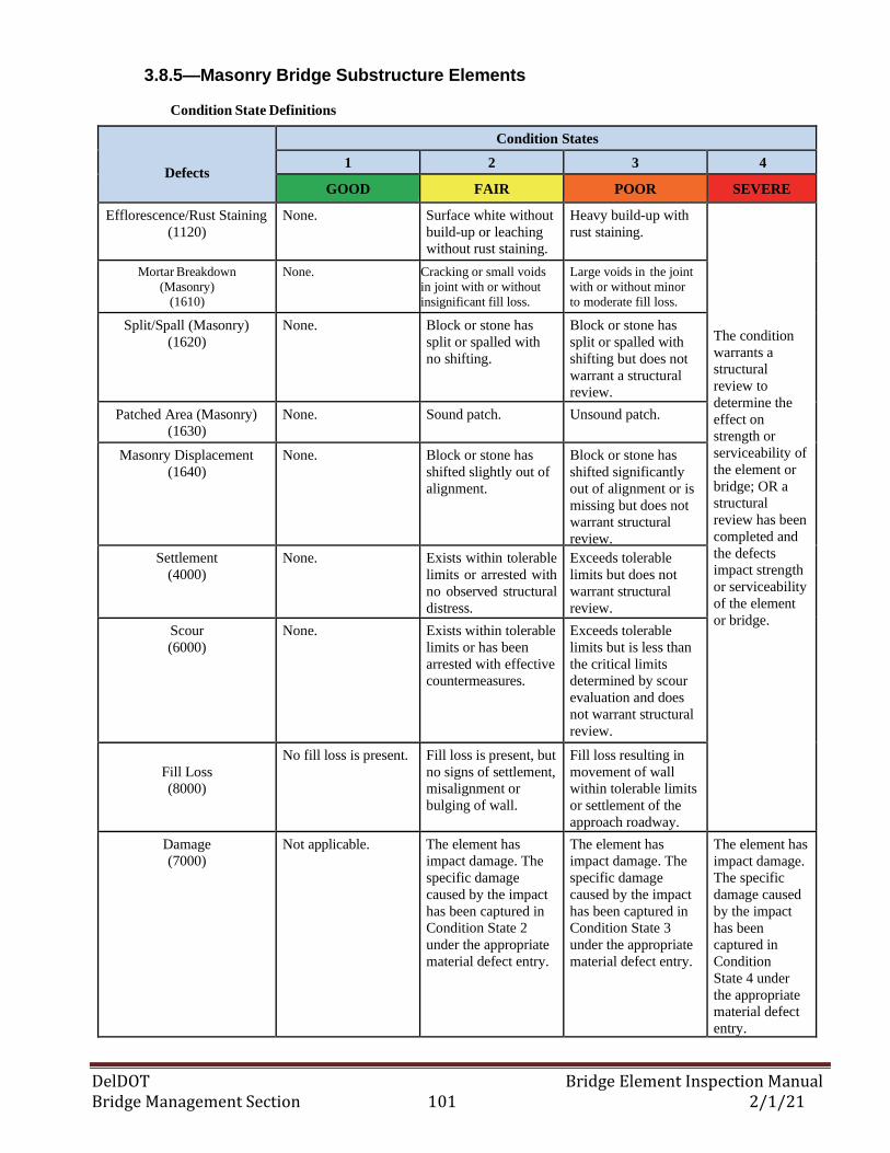
DelDOT Bridge Element Inspection Manual Bridge Management Section 101 2/1/21
3.8.5—Masonry Bridge Substructure Elements
Condition State Definitions
Defects
Condition States
1 2 3 4
GOOD FAIR POOR SEVERE
Efflorescence/Rust Staining
(1120)
None. Surface white without
build-up or leaching
without rust staining.
Heavy build-up with
rust staining.
The condition
warrants a
structural
review to
determine the
effect on
strength or
serviceability of
the element or
bridge; OR a
structural
review has been
completed and
the defects
impact strength
or serviceability
of the element
or bridge.
Mortar Breakdown
(Masonry) (1610)
None. Cracking or small voids
in joint with or without
insignificant fill loss.
Large voids in the joint
with or without minor
to moderate fill loss.
Split/Spall (Masonry)
(1620)
None. Block or stone has
split or spalled with
no shifting.
Block or stone has
split or spalled with
shifting but does not
warrant a structural
review.
Patched Area (Masonry)
(1630)
None. Sound patch. Unsound patch.
Masonry Displacement
(1640)
None. Block or stone has
shifted slightly out of
alignment.
Block or stone has
shifted significantly
out of alignment or is
missing but does not
warrant structural
review.
Settlement
(4000)
None. Exists within tolerable
limits or arrested with
no observed structural
distress.
Exceeds tolerable
limits but does not
warrant structural
review.
Scour
(6000)
None. Exists within tolerable
limits or has been
arrested with effective
countermeasures.
Exceeds tolerable
limits but is less than
the critical limits
determined by scour
evaluation and does
not warrant structural
review.
Fill Loss
(8000)
No fill loss is present. Fill loss is present, but
no signs of settlement,
misalignment or
bulging of wall.
Fill loss resulting in
movement of wall
within tolerable limits
or settlement of the
approach roadway.
Damage
(7000)
Not applicable. The element has
impact damage. The
specific damage
caused by the impact
has been captured in
Condition State 2
under the appropriate
material defect entry.
The element has
impact damage. The
specific damage
caused by the impact
has been captured in
Condition State 3
under the appropriate
material defect entry.
The element has
impact damage.
The specific
damage caused
by the impact
has been
captured in
Condition
State 4 under
the appropriate
material defect
entry.
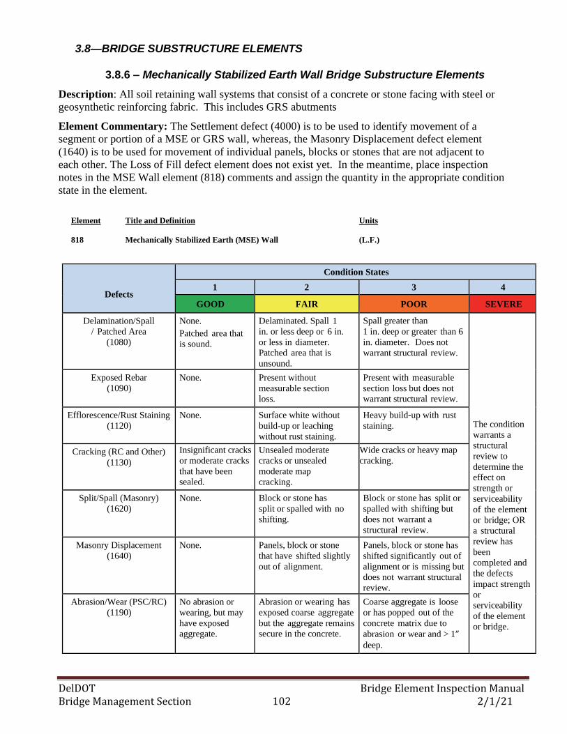
DelDOT Bridge Element Inspection Manual Bridge Management Section 102 2/1/21
3.8—BRIDGE SUBSTRUCTURE ELEMENTS
3.8.6 – Mechanically Stabilized Earth Wall Bridge Substructure Elements
Description: All soil retaining wall systems that consist of a concrete or stone facing with steel or
geosynthetic reinforcing fabric. This includes GRS abutments
Element Commentary: The Settlement defect (4000) is to be used to identify movement of a
segment or portion of a MSE or GRS wall, whereas, the Masonry Displacement defect element
(1640) is to be used for movement of individual panels, blocks or stones that are not adjacent to
each other. The Loss of Fill defect element does not exist yet. In the meantime, place inspection
notes in the MSE Wall element (818) comments and assign the quantity in the appropriate condition
state in the element.
Element Title and Definition Units
818 Mechanically Stabilized Earth (MSE) Wall (L.F.)
Defects
Condition States
1 2 3 4
GOOD FAIR POOR SEVERE
Delamination/Spall
/ Patched Area
(1080)
None.
Patched area that
is sound.
Delaminated. Spall 1
in. or less deep or 6 in.
or less in diameter.
Patched area that is
unsound.
Spall greater than
1 in. deep or greater than 6
in. diameter. Does not
warrant structural review.
The condition
warrants a
structural
review to
determine the
effect on
strength or
serviceability
of the element
or bridge; OR
a structural
review has
been
completed and
the defects
impact strength
or
serviceability
of the element
or bridge.
Exposed Rebar
(1090)
None. Present without
measurable section
loss.
Present with measurable
section loss but does not
warrant structural review.
Efflorescence/Rust Staining
(1120)
None. Surface white without
build-up or leaching
without rust staining.
Heavy build-up with rust
staining.
Cracking (RC and Other)
(1130)
Insignificant cracks
or moderate cracks
that have been
sealed.
Unsealed moderate
cracks or unsealed
moderate map
cracking.
Wide cracks or heavy map
cracking.
Split/Spall (Masonry)
(1620)
None. Block or stone has
split or spalled with no
shifting.
Block or stone has split or
spalled with shifting but
does not warrant a
structural review.
Masonry Displacement
(1640)
None. Panels, block or stone
that have shifted slightly
out of alignment.
Panels, block or stone has
shifted significantly out of
alignment or is missing but
does not warrant structural
review.
Abrasion/Wear (PSC/RC)
(1190)
No abrasion or
wearing, but may
have exposed
aggregate.
Abrasion or wearing has
exposed coarse aggregate
but the aggregate remains
secure in the concrete.
Coarse aggregate is loose
or has popped out of the
concrete matrix due to
abrasion or wear and > 1” deep.
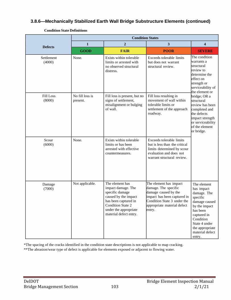
DelDOT Bridge Element Inspection Manual Bridge Management Section 103 2/1/21
3.8.6—Mechanically Stabilized Earth Wall Bridge Substructure Elements (continued)
Condition State Definitions
Defects
Condition States
1 2 3 4
GOOD FAIR POOR SEVERE
Settlement
(4000)
None. Exists within tolerable
limits or arrested with
no observed structural
distress.
Exceeds tolerable limits
but does not warrant
structural review.
The condition
warrants a
structural
review to
determine the
effect on
strength or
serviceability of
the element or
bridge; OR a
structural
review has been
completed and
the defects
impact strength
or serviceability
of the element
or bridge.
Fill Loss
(8000)
No fill loss is
present.
Fill loss is present, but no
signs of settlement,
misalignment or bulging
of wall.
Fill loss resulting in
movement of wall within
tolerable limits or
settlement of the approach
roadway.
Scour
(6000)
None. Exists within tolerable
limits or has been
arrested with effective
countermeasures.
Exceeds tolerable limits
but is less than the critical
limits determined by scour
evaluation and does not
warrant structural review.
Damage
(7000)
Not applicable. The element has
impact damage. The
specific damage
caused by the impact
has been captured in
Condition State 2
under the appropriate
material defect entry.
The element has impact
damage. The specific
damage caused by the
impact has been captured in
Condition State 3 under the
appropriate material defect
entry.
The element
has impact
damage. The
specific
damage caused
by the impact
has been
captured in
Condition
State 4 under
the appropriate
material defect
entry.
*The spacing of the cracks identified in the condition state descriptions is not applicable to map cracking.
**The abrasion/wear type of defect is applicable for elements exposed or adjacent to flowing water.
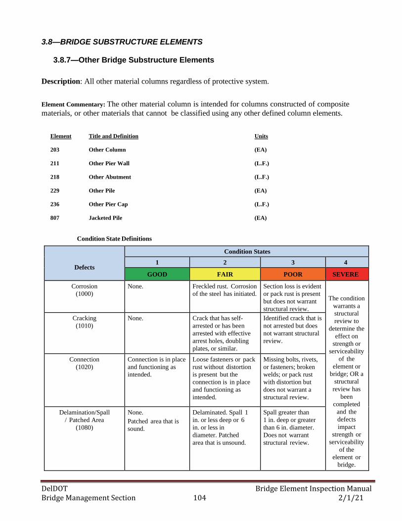
DelDOT Bridge Element Inspection Manual Bridge Management Section 104 2/1/21
3.8—BRIDGE SUBSTRUCTURE ELEMENTS
3.8.7—Other Bridge Substructure Elements
Description: All other material columns regardless of protective system.
Element Commentary: The other material column is intended for columns constructed of composite
materials, or other materials that cannot be classified using any other defined column elements.
Element Title and Definition Units
203 Other Column (EA)
211 Other Pier Wall (L.F.)
218 Other Abutment (L.F.)
229 Other Pile (EA)
236 Other Pier Cap (L.F.)
807 Jacketed Pile (EA)
Condition State Definitions
Defects
Condition States
1 2 3 4
GOOD FAIR POOR SEVERE
Corrosion
(1000)
None. Freckled rust. Corrosion
of the steel has initiated.
Section loss is evident
or pack rust is present
but does not warrant
structural review.
The condition
warrants a
structural
review to
determine the
effect on
strength or
serviceability
of the
element or
bridge; OR a
structural
review has
been
completed
and the
defects
impact
strength or
serviceability
of the
element or
bridge.
Cracking
(1010)
None. Crack that has self-
arrested or has been
arrested with effective
arrest holes, doubling
plates, or similar.
Identified crack that is
not arrested but does
not warrant structural
review.
Connection
(1020)
Connection is in place
and functioning as
intended.
Loose fasteners or pack
rust without distortion
is present but the
connection is in place
and functioning as
intended.
Missing bolts, rivets,
or fasteners; broken
welds; or pack rust
with distortion but
does not warrant a
structural review.
Delamination/Spall
/ Patched Area
(1080)
None.
Patched area that is
sound.
Delaminated. Spall 1
in. or less deep or 6
in. or less in
diameter. Patched
area that is unsound.
Spall greater than
1 in. deep or greater
than 6 in. diameter.
Does not warrant
structural review.
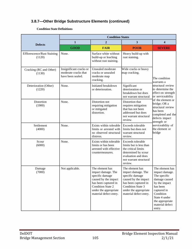
DelDOT Bridge Element Inspection Manual Bridge Management Section 105 2/1/21
3.8.7—Other Bridge Substructure Elements (continued)
Condition State Definitions
Defects
Condition States
1 2 3 4
GOOD FAIR POOR SEVERE
Efflorescence/Rust Staining
(1120)
None. Surface white without
build-up or leaching
without rust staining.
Heavy build-up with
rust staining.
The condition
warrants a
structural review
to determine the
effect on strength
or serviceability
of the element or
bridge; OR a
structural review
has been
completed and the
defects impact
strength or
serviceability of
the element or
bridge
Cracking (RC and Other)
(1130)
Insignificant cracks or
moderate cracks that
have been sealed.
Unsealed moderate
cracks or unsealed
moderate map
cracking.
Wide cracks or heavy
map cracking.
Deterioration (Other)
(1220)
None. Initiated breakdown
or deterioration.
Significant
deterioration or
breakdown but does
not warrant structural
review. Distortion
(1900)
None. Distortion not
requiring mitigation
or mitigated
distortion.
Distortion that
requires mitigation
that has not been
addressed but does
not warrant structural
review.
Settlement
(4000)
None. Exists within tolerable
limits or arrested with
no observed structural
distress.
Exceeds tolerable
limits but does not
warrant structural
review.
Scour
(6000)
None. Exists within tolerable
limits or has been
arrested with effective
countermeasures.
Exceeds tolerable
limits but is less than
the critical limits
determined by scour
evaluation and does
not warrant structural
review.
Damage
(7000)
Not applicable. The element has
impact damage. The
specific damage
caused by the impact
has been captured in
Condition State 2
under the appropriate
material defect entry.
The element has
impact damage. The
specific damage
caused by the impact
has been captured in
Condition State 3
under the appropriate
material defect entry.
The element has
impact damage.
The specific
damage caused
by the impact
has been
captured in
Condition
State 4 under
the appropriate
material defect
entry.
DelDOT Bridge Element Inspection Manual Bridge Management Section 106 2/1/21
3.9—BRIDGE CULVERT ELEMENTS
3.9.1—Steel Culvert Elements
Description: Those bridge culvert structures constructed of steel including arch, round or elliptical
pipes regardless of protective systems.
Element Commentary: The Steel Culvert – Major element (844) shall be used for culverts with a 7’ or
greater span length. The Steel Culvert element (240) shall be used for steel pipe culverts that have a span
length less than 7’. The distortion defect is contingent on a number of factors such as site, wall
thickness, and fill depth. The inspector shall use such factors to assess the proper condition state.
Regarding pipe joint or seam connections that exhibit separation and/or loss of fill, the Connection
(1020), Distortion (1900) or Settlement (4000) defect elements may be utilized to account for and
document the deterioration/defect. If the seam has broken bolts, the Connection (1020) element should
be considered. Similarly, if distortion of the pipe has caused the seam/joint to break or alter the shape of
the pipe allowing fill loss to occur at the joint, then the Distortion (1900) defect should be considered.
For misaligned pipe segments, the Distortion (1900) defect element shall be used to identify and
document alignment defects.
Element Title and Definition Units
240 Steel Culvert (L.F.)
844 Steel Culvert - Major (L.F.)
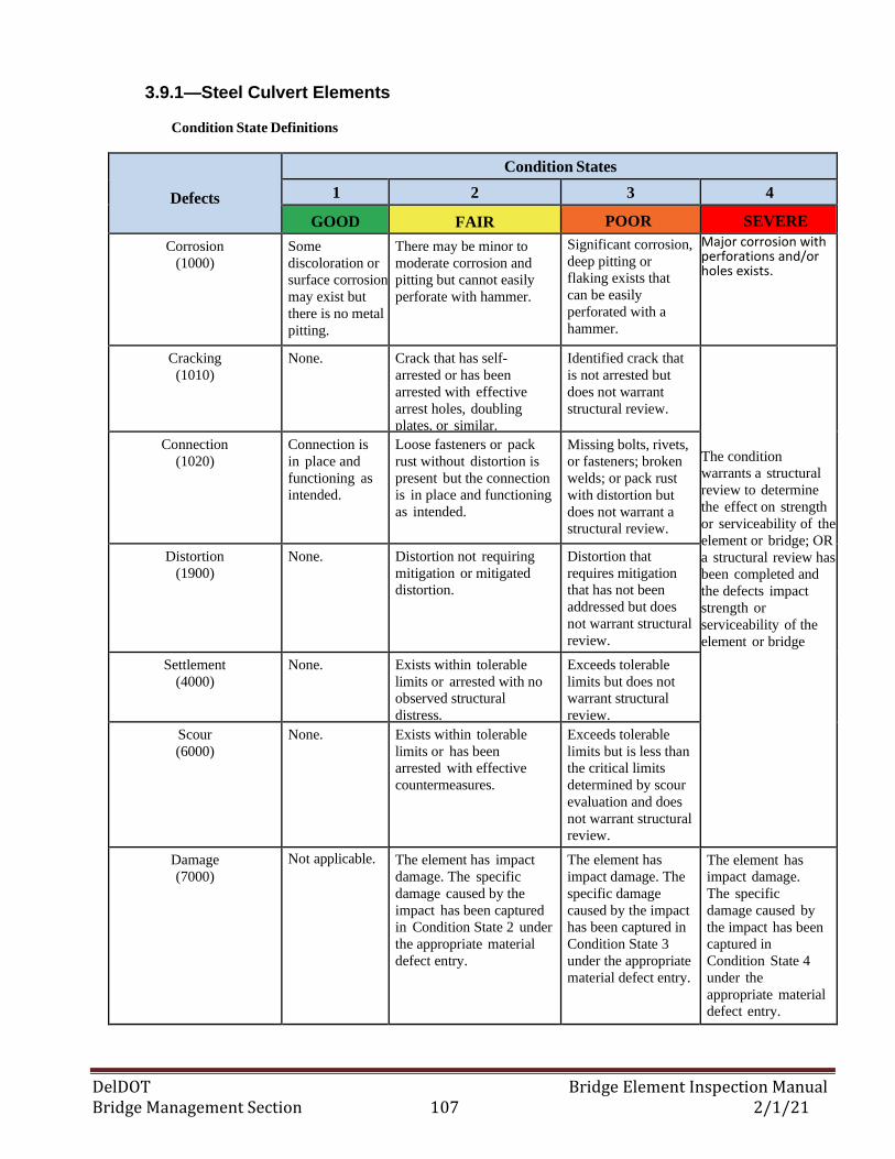
DelDOT Bridge Element Inspection Manual Bridge Management Section 107 2/1/21
3.9.1—Steel Culvert Elements
Condition State Definitions
Defects
Condition States
1 2 3 4
GOOD FAIR POOR SEVERE
Corrosion
(1000)
Some
discoloration or
surface corrosion
may exist but
there is no metal
pitting.
There may be minor to
moderate corrosion and
pitting but cannot easily
perforate with hammer.
Significant corrosion,
deep pitting or
flaking exists that
can be easily
perforated with a
hammer.
Major corrosion with perforations and/or holes exists. The condition
warrants a structural
review to determine
the effect on
strength or
serviceability of the
element or bridge;
OR a structural
review has been
completed and the
defects impact
strength or
serviceability of the
element or bridge.
Cracking
(1010)
None. Crack that has self-
arrested or has been
arrested with effective
arrest holes, doubling
plates, or similar.
Identified crack that
is not arrested but
does not warrant
structural review.
The condition
warrants a structural
review to determine
the effect on strength
or serviceability of the
element or bridge; OR
a structural review has
been completed and
the defects impact
strength or
serviceability of the
element or bridge
Connection
(1020)
Connection is
in place and
functioning as
intended.
Loose fasteners or pack
rust without distortion is
present but the connection
is in place and functioning
as intended.
Missing bolts, rivets,
or fasteners; broken
welds; or pack rust
with distortion but
does not warrant a
structural review.
Distortion
(1900)
None. Distortion not requiring
mitigation or mitigated
distortion.
Distortion that
requires mitigation
that has not been
addressed but does
not warrant structural
review.
Settlement
(4000)
None. Exists within tolerable
limits or arrested with no
observed structural
distress.
Exceeds tolerable
limits but does not
warrant structural
review.
Scour
(6000)
None. Exists within tolerable
limits or has been
arrested with effective
countermeasures.
Exceeds tolerable
limits but is less than
the critical limits
determined by scour
evaluation and does
not warrant structural
review.
Damage
(7000)
Not applicable. The element has impact
damage. The specific
damage caused by the
impact has been captured
in Condition State 2 under
the appropriate material
defect entry.
The element has
impact damage. The
specific damage
caused by the impact
has been captured in
Condition State 3
under the appropriate
material defect entry.
The element has
impact damage.
The specific
damage caused by
the impact has been
captured in
Condition State 4
under the
appropriate material
defect entry.
DelDOT Bridge Element Inspection Manual Bridge Management Section 108 2/1/21
3.9—BRIDGE CULVERT ELEMENTS
3.9.2—Aluminum Culvert Elements
Description: Those bridge culvert structures constructed of aluminum including arch, round or
elliptical pipes regardless of protective systems.
Element Commentary: The Aluminum Culvert – Major element (848) shall be used for culverts with a
7’ or greater span length. The Aluminum Culvert element (847) shall be used for aluminum pipe culverts
that have a span length less than 7’. The distortion defect is contingent on a number of factors such as
site, wall thickness, and fill depth. The inspector shall use such factors to assess the proper condition
state.
When inspecting aluminum pipes, the inspection team shall not use a hammer since the corrosion occurs
from the outside towards the inside and as a result, the inspection is more of a visual inspection.
Regarding pipe joint or seam connections that exhibit separation and/or loss of fill, the Connection
(1020), Distortion (1900) or Settlement (4000) defect elements may be utilized to account for and
document the deterioration/defect. If the seam has broken bolts, the Connection (1020) element should
be considered. Similarly, if distortion of the pipe has caused the seam/joint to break or alter the shape of
the pipe allowing fill loss to occur at the joint, then the Distortion (1900) defect should be considered.
For misaligned pipe segments, the Distortion (1900) defect element shall be used to identify and
document alignment defects.
Element Title and Definition Units
847 Aluminum Culvert - Minor (L.F.)
848 Aluminum Culvert - Major (L.F.)
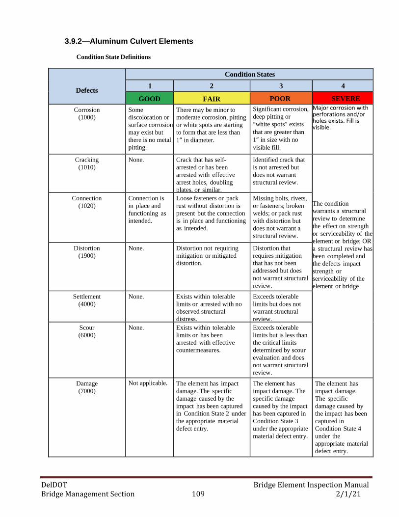
DelDOT Bridge Element Inspection Manual Bridge Management Section 109 2/1/21
3.9.2—Aluminum Culvert Elements
Condition State Definitions
Defects
Condition States
1 2 3 4
GOOD FAIR POOR SEVERE
Corrosion
(1000)
Some
discoloration or
surface corrosion
may exist but
there is no metal
pitting.
There may be minor to
moderate corrosion, pitting
or white spots are starting
to form that are less than
1” in diameter.
Significant corrosion,
deep pitting or
“white spots” exists
that are greater than
1” in size with no
visible fill.
Major corrosion with perforations and/or holes exists. Fill is visible. The condition
warrants a structural
review to determine
the effect on
strength or
serviceability of the
element or bridge;
OR a structural
review has been
completed and the
defects impact
strength or
serviceability of the
element or bridge.
Cracking
(1010)
None. Crack that has self-
arrested or has been
arrested with effective
arrest holes, doubling
plates, or similar.
Identified crack that
is not arrested but
does not warrant
structural review.
The condition
warrants a structural
review to determine
the effect on strength
or serviceability of the
element or bridge; OR
a structural review has
been completed and
the defects impact
strength or
serviceability of the
element or bridge
Connection
(1020)
Connection is
in place and
functioning as
intended.
Loose fasteners or pack
rust without distortion is
present but the connection
is in place and functioning
as intended.
Missing bolts, rivets,
or fasteners; broken
welds; or pack rust
with distortion but
does not warrant a
structural review.
Distortion
(1900)
None. Distortion not requiring
mitigation or mitigated
distortion.
Distortion that
requires mitigation
that has not been
addressed but does
not warrant structural
review.
Settlement
(4000)
None. Exists within tolerable
limits or arrested with no
observed structural
distress.
Exceeds tolerable
limits but does not
warrant structural
review.
Scour
(6000)
None. Exists within tolerable
limits or has been
arrested with effective
countermeasures.
Exceeds tolerable
limits but is less than
the critical limits
determined by scour
evaluation and does
not warrant structural
review.
Damage
(7000)
Not applicable. The element has impact
damage. The specific
damage caused by the
impact has been captured
in Condition State 2 under
the appropriate material
defect entry.
The element has
impact damage. The
specific damage
caused by the impact
has been captured in
Condition State 3
under the appropriate
material defect entry.
The element has
impact damage.
The specific
damage caused by
the impact has been
captured in
Condition State 4
under the
appropriate material
defect entry.
DelDOT Bridge Element Inspection Manual Bridge Management Section 110 2/1/21
3.9—BRIDGE CULVERT ELEMENTS
3.9.3—Reinforced Concrete Culvert Elements
Description: Those bridge culvert structures constructed of reinforced concrete including arch,
round or elliptical pipes and box and frame culverts regardless of protective systems.
Element Commentary: The Reinforced Concrete Culvert – Major element (845) shall be used for box
and frame culverts regardless of span length. Scaling in the floor of a box culvert shall remain in CS1; this
includes deep scaling. The Reinforce Concrete Culvert element (241) shall be used for reinforced concrete
pipe culverts including arch, round and elliptical pipes regardless of span length. The distortion defect is
contingent on a number of factors such as site, wall thickness, and fill depth. The inspector shall use
such factors to assess the proper condition state.
Regarding pipe joint or seam connections that exhibit separation and/or loss of fill, the Settlement (4000)
or the Distortion (1900) defect elements should be utilized to account for and document the
deterioration/defect using the guidance provided below.
CS1: Pipe joint gaps/seams are not within tolerable limits but no signs of fill loss.
CS2: Pipe Joint gaps/seams are not within tolerable limits with minor loss of fill.
CS3: Pipe joint gaps/seams are not within tolerable limits and have moderate to advanced fill loss that
doesn’t warrant structural review. May also include separated joints with exposed fill.
CS4: Advanced fill loss causing settlement or distortion that warrants structural review.
For misaligned pipe segments, the Distortion (1900) defect element shall be used to identify and
document alignment defects.
Element Title and Definition Units
241 Reinforced Concrete Culvert (L.F.)
845 Reinforced Concrete Culvert - Major (L.F.)
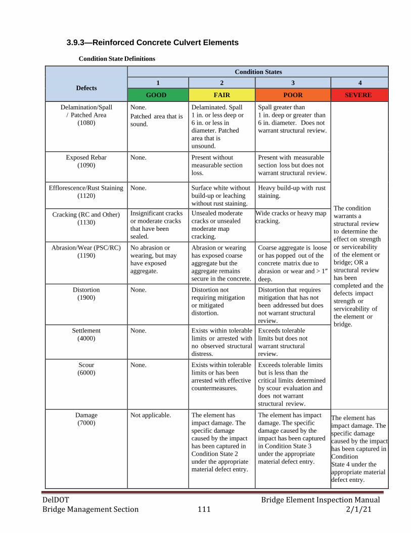
DelDOT Bridge Element Inspection Manual Bridge Management Section 111 2/1/21
3.9.3—Reinforced Concrete Culvert Elements
Condition State Definitions
Defects
Condition States
1 2 3 4
GOOD FAIR POOR SEVERE
Delamination/Spall
/ Patched Area
(1080)
None.
Patched area that is
sound.
Delaminated. Spall
1 in. or less deep or
6 in. or less in
diameter. Patched
area that is
unsound.
Spall greater than
1 in. deep or greater than
6 in. diameter. Does not
warrant structural review.
The condition
warrants a
structural review
to determine the
effect on strength
or serviceability
of the element or
bridge; OR a
structural review
has been
completed and the
defects impact
strength or
serviceability of
the element or
bridge.
Exposed Rebar
(1090)
None. Present without
measurable section
loss.
Present with measurable
section loss but does not
warrant structural review.
Efflorescence/Rust Staining
(1120)
None. Surface white without
build-up or leaching
without rust staining.
Heavy build-up with rust
staining.
Cracking (RC and Other)
(1130)
Insignificant cracks
or moderate cracks
that have been
sealed.
Unsealed moderate
cracks or unsealed
moderate map
cracking.
Wide cracks or heavy map
cracking.
Abrasion/Wear (PSC/RC)
(1190)
No abrasion or
wearing, but may
have exposed
aggregate.
Abrasion or wearing
has exposed coarse
aggregate but the
aggregate remains
secure in the concrete.
Coarse aggregate is loose
or has popped out of the
concrete matrix due to
abrasion or wear and > 1” deep.
Distortion
(1900)
None. Distortion not
requiring mitigation
or mitigated
distortion.
Distortion that requires
mitigation that has not
been addressed but does
not warrant structural
review.
Settlement
(4000)
None. Exists within tolerable
limits or arrested with
no observed structural
distress.
Exceeds tolerable
limits but does not
warrant structural
review.
Scour
(6000)
None. Exists within tolerable
limits or has been
arrested with effective
countermeasures.
Exceeds tolerable limits
but is less than the
critical limits determined
by scour evaluation and
does not warrant
structural review.
Damage
(7000)
Not applicable. The element has
impact damage. The
specific damage
caused by the impact
has been captured in
Condition State 2
under the appropriate
material defect entry.
The element has impact
damage. The specific
damage caused by the
impact has been captured
in Condition State 3
under the appropriate
material defect entry.
The element has
impact damage. The
specific damage
caused by the impact
has been captured in
Condition
State 4 under the
appropriate material
defect entry.
DelDOT Bridge Element Inspection Manual Bridge Management Section 112 2/1/21
3.9—BRIDGE CULVERT ELEMENTS 3.9.4—Masonry Culvert Element
Description: Those bridge culvert structures constructed of masonry.
Element Commentary: The distortion defect is contingent on a number of factors such as site, wall
thickness, and fill depth. The inspector shall use such factors to assess the proper condition state
Element Title and Definition Units
244 Masonry Culvert (L.F.)
897 Masonry Headwall (L.F.)
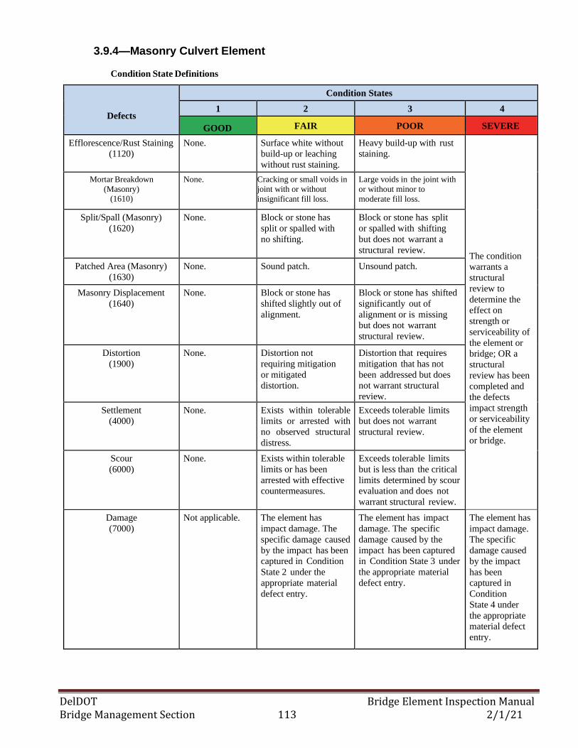
DelDOT Bridge Element Inspection Manual Bridge Management Section 113 2/1/21
3.9.4—Masonry Culvert Element
Condition State Definitions
Defects
Condition States
1 2 3 4
GOOD FAIR POOR SEVERE
Efflorescence/Rust Staining
(1120)
None. Surface white without
build-up or leaching
without rust staining.
Heavy build-up with rust
staining.
The condition
warrants a
structural
review to
determine the
effect on
strength or
serviceability of
the element or
bridge; OR a
structural
review has been
completed and
the defects
impact strength
or serviceability
of the element
or bridge.
Mortar Breakdown
(Masonry) (1610)
None. Cracking or small voids in
joint with or without
insignificant fill loss.
Large voids in the joint with
or without minor to
moderate fill loss.
Split/Spall (Masonry)
(1620)
None. Block or stone has
split or spalled with
no shifting.
Block or stone has split
or spalled with shifting
but does not warrant a
structural review.
Patched Area (Masonry)
(1630)
None. Sound patch. Unsound patch.
Masonry Displacement
(1640)
None. Block or stone has
shifted slightly out of
alignment.
Block or stone has shifted
significantly out of
alignment or is missing
but does not warrant
structural review.
Distortion
(1900)
None. Distortion not
requiring mitigation
or mitigated
distortion.
Distortion that requires
mitigation that has not
been addressed but does
not warrant structural
review.
Settlement
(4000)
None. Exists within tolerable
limits or arrested with
no observed structural
distress.
Exceeds tolerable limits
but does not warrant
structural review.
Scour
(6000)
None. Exists within tolerable
limits or has been
arrested with effective
countermeasures.
Exceeds tolerable limits
but is less than the critical
limits determined by scour
evaluation and does not
warrant structural review.
Damage
(7000)
Not applicable. The element has
impact damage. The
specific damage caused
by the impact has been
captured in Condition
State 2 under the
appropriate material
defect entry.
The element has impact
damage. The specific
damage caused by the
impact has been captured
in Condition State 3 under
the appropriate material
defect entry.
The element has
impact damage.
The specific
damage caused
by the impact
has been
captured in
Condition
State 4 under
the appropriate
material defect
entry.
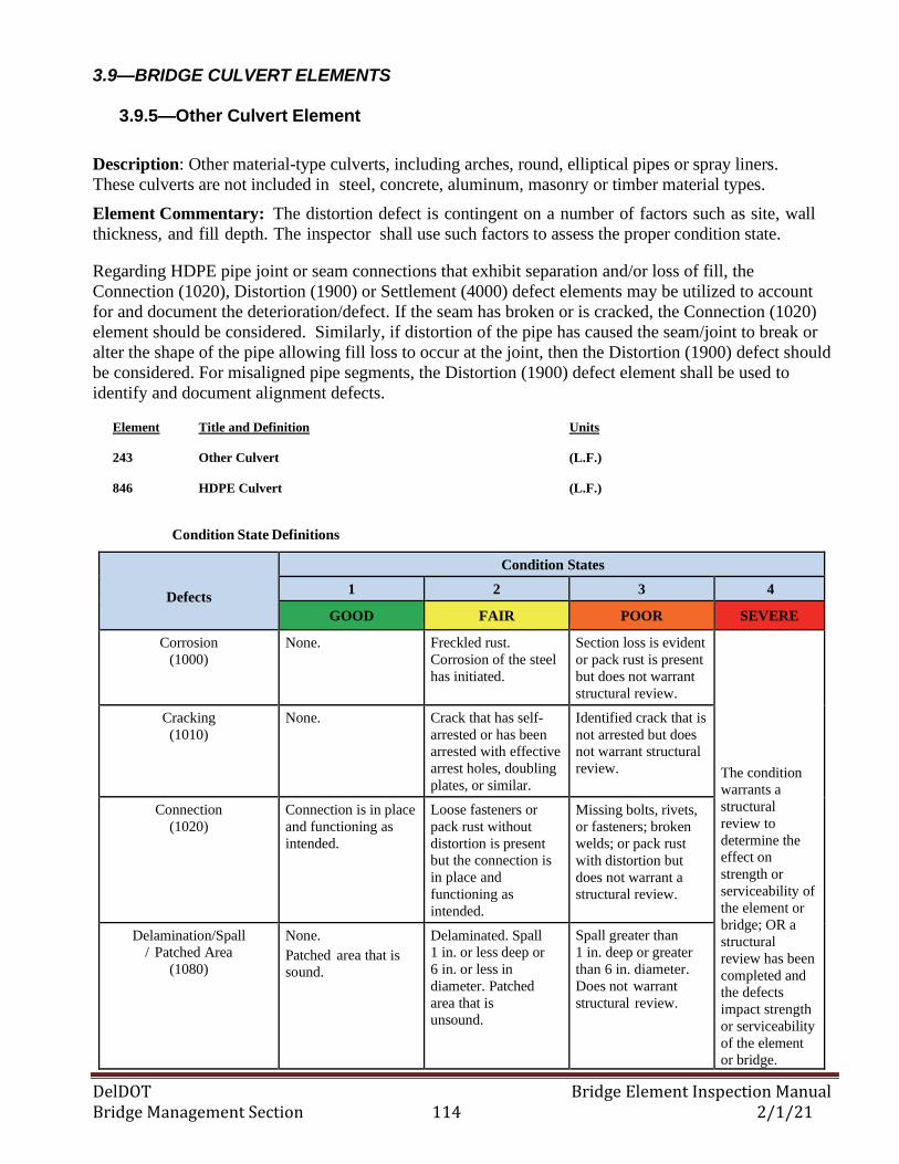
DelDOT Bridge Element Inspection Manual Bridge Management Section 114 2/1/21
3.9—BRIDGE CULVERT ELEMENTS
3.9.5—Other Culvert Element
Description: Other material-type culverts, including arches, round, elliptical pipes or spray liners.
These culverts are not included in steel, concrete, aluminum, masonry or timber material types.
Element Commentary: The distortion defect is contingent on a number of factors such as site, wall
thickness, and fill depth. The inspector shall use such factors to assess the proper condition state.
Regarding HDPE pipe joint or seam connections that exhibit separation and/or loss of fill, the
Connection (1020), Distortion (1900) or Settlement (4000) defect elements may be utilized to account
for and document the deterioration/defect. If the seam has broken or is cracked, the Connection (1020)
element should be considered. Similarly, if distortion of the pipe has caused the seam/joint to break or
alter the shape of the pipe allowing fill loss to occur at the joint, then the Distortion (1900) defect should
be considered. For misaligned pipe segments, the Distortion (1900) defect element shall be used to
identify and document alignment defects.
Element Title and Definition Units
243 Other Culvert (L.F.)
846 HDPE Culvert (L.F.)
Condition State Definitions
Defects
Condition States
1 2 3 4
GOOD FAIR POOR SEVERE
Corrosion
(1000)
None. Freckled rust.
Corrosion of the steel
has initiated.
Section loss is evident
or pack rust is present
but does not warrant
structural review.
The condition
warrants a
structural
review to
determine the
effect on
strength or
serviceability of
the element or
bridge; OR a
structural
review has been
completed and
the defects
impact strength
or serviceability
of the element
or bridge.
Cracking
(1010)
None. Crack that has self-
arrested or has been
arrested with effective
arrest holes, doubling
plates, or similar.
Identified crack that is
not arrested but does
not warrant structural
review.
Connection
(1020)
Connection is in place
and functioning as
intended.
Loose fasteners or
pack rust without
distortion is present
but the connection is
in place and
functioning as
intended.
Missing bolts, rivets,
or fasteners; broken
welds; or pack rust
with distortion but
does not warrant a
structural review.
Delamination/Spall
/ Patched Area
(1080)
None.
Patched area that is
sound.
Delaminated. Spall
1 in. or less deep or
6 in. or less in
diameter. Patched
area that is
unsound.
Spall greater than
1 in. deep or greater
than 6 in. diameter.
Does not warrant
structural review.
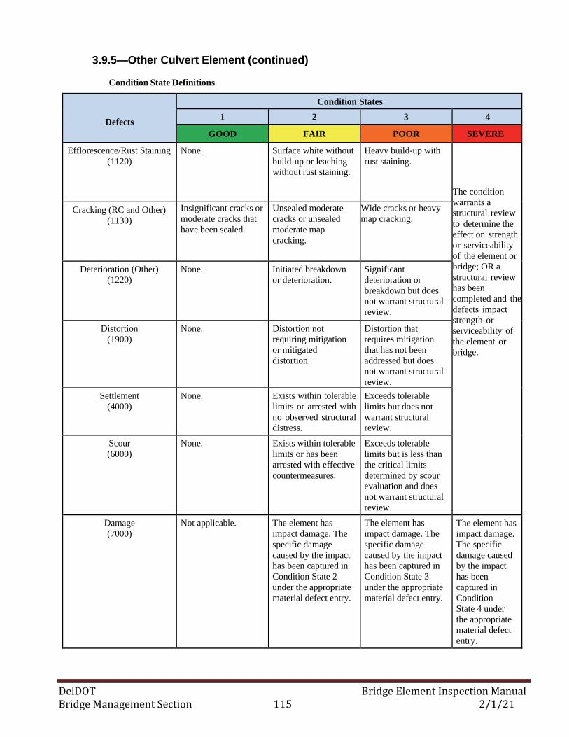
DelDOT Bridge Element Inspection Manual Bridge Management Section 115 2/1/21
3.9.5—Other Culvert Element (continued)
Condition State Definitions
Defects
Condition States
1 2 3 4
GOOD FAIR POOR SEVERE
Efflorescence/Rust Staining
(1120)
None. Surface white without
build-up or leaching
without rust staining.
Heavy build-up with
rust staining.
The condition
warrants a
structural review
to determine the
effect on strength
or serviceability
of the element or
bridge; OR a
structural review
has been
completed and the
defects impact
strength or
serviceability of
the element or
bridge.
Cracking (RC and Other)
(1130)
Insignificant cracks or
moderate cracks that
have been sealed.
Unsealed moderate
cracks or unsealed
moderate map
cracking.
Wide cracks or heavy
map cracking.
Deterioration (Other)
(1220)
None. Initiated breakdown
or deterioration.
Significant
deterioration or
breakdown but does
not warrant structural
review.
Distortion
(1900)
None. Distortion not
requiring mitigation
or mitigated
distortion.
Distortion that
requires mitigation
that has not been
addressed but does
not warrant structural
review.
Settlement
(4000)
None. Exists within tolerable
limits or arrested with
no observed structural
distress.
Exceeds tolerable
limits but does not
warrant structural
review.
Scour
(6000)
None. Exists within tolerable
limits or has been
arrested with effective
countermeasures.
Exceeds tolerable
limits but is less than
the critical limits
determined by scour
evaluation and does
not warrant structural
review.
Damage
(7000)
Not applicable. The element has
impact damage. The
specific damage
caused by the impact
has been captured in
Condition State 2
under the appropriate
material defect entry.
The element has
impact damage. The
specific damage
caused by the impact
has been captured in
Condition State 3
under the appropriate
material defect entry.
The element has
impact damage.
The specific
damage caused
by the impact
has been
captured in
Condition
State 4 under
the appropriate
material defect
entry.
DelDOT Bridge Element Inspection Manual Bridge Management Section 116 2/1/21
3.9—BRIDGE CULVERT ELEMENTS 3.9.6—Sacked Concrete Wall Element
Description: Those bridge walls belonging to pipe culvert structures that are constructed of sacked
concrete bags.
Element Commentary: The defects for sacked concrete walls follows the defects for masonry walls
since they are similar in nature. The distortion defect is contingent on a number of factors such as site,
wall thickness, and fill depth. The inspector shall use such factors to assess the proper condition state
Element Title and Definition Units
895 Sacked Concrete Wall (FT2)
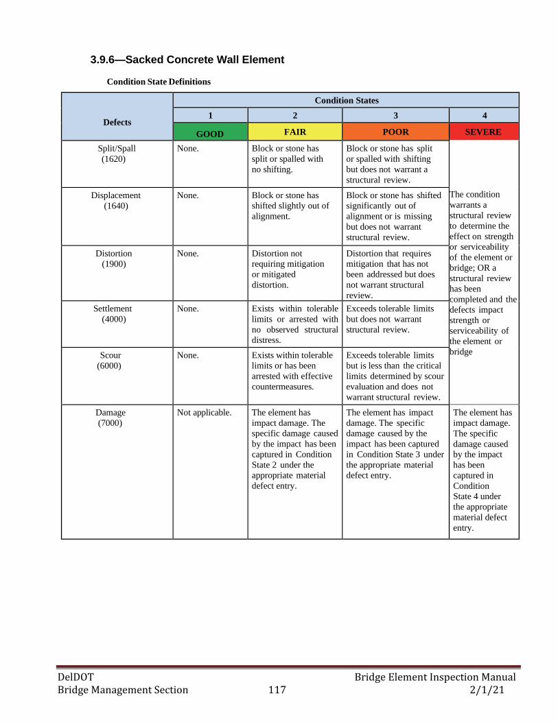
DelDOT Bridge Element Inspection Manual Bridge Management Section 117 2/1/21
3.9.6—Sacked Concrete Wall Element
Condition State Definitions
Defects
Condition States
1 2 3 4
GOOD FAIR POOR SEVERE
Split/Spall
(1620)
None. Block or stone has
split or spalled with
no shifting.
Block or stone has split
or spalled with shifting
but does not warrant a
structural review.
The condition
warrants a
structural review
to determine the
effect on strength
or serviceability
of the element or
bridge; OR a
structural review
has been
completed and the
defects impact
strength or
serviceability of
the element or
bridge
Displacement
(1640)
None. Block or stone has
shifted slightly out of
alignment.
Block or stone has shifted
significantly out of
alignment or is missing
but does not warrant
structural review.
Distortion
(1900)
None. Distortion not
requiring mitigation
or mitigated
distortion.
Distortion that requires
mitigation that has not
been addressed but does
not warrant structural
review.
Settlement
(4000)
None. Exists within tolerable
limits or arrested with
no observed structural
distress.
Exceeds tolerable limits
but does not warrant
structural review.
Scour
(6000)
None. Exists within tolerable
limits or has been
arrested with effective
countermeasures.
Exceeds tolerable limits
but is less than the critical
limits determined by scour
evaluation and does not
warrant structural review.
Damage
(7000)
Not applicable. The element has
impact damage. The
specific damage caused
by the impact has been
captured in Condition
State 2 under the
appropriate material
defect entry.
The element has impact
damage. The specific
damage caused by the
impact has been captured
in Condition State 3 under
the appropriate material
defect entry.
The element has
impact damage.
The specific
damage caused
by the impact
has been
captured in
Condition
State 4 under
the appropriate
material defect
entry.
DelDOT Bridge Element Inspection Manual Bridge Management Section 118 2/1/21
3.10—WEARING SURFACES, PROTECTIVE COATINGS, AND CONCRETE REINFORCING STEEL PROTECTIVE SYSTEMS
3.10.1— Wearing Surface Elements
Description: All decks/slabs that have Non-Structural overlays made with flexible (asphaltic concrete),
semi-rigid (epoxy and polyester material), and rigid (portland cement) materials; and timber running
planks. If an original bare concrete deck was milled and replaced with LMC or Class D concrete back to
its original depth, then that is considered Structural Resurfacing and a Wearing Surface Element shall
not be created.
Element Title and Definition Units
510 Wearing Surfaces: Rigid Overlay (FT2)
810 Wearing Surface: Thin Overlay (FT2)
811 Wearing Surface: Asphaltic Concrete Overlay (FT2)
812 Wearing Surface: Timber Planking (FT2)

DelDOT Bridge Element Inspection Manual Bridge Management Section 119 2/1/21
3.10.1— Wearing Surface Elements
Condition State Definitions
Defects
Condition States
1 2 3 4
GOOD FAIR POOR SEVERE
Delamination/Spall/
Patched Area/Pothole
(Wearing Surfaces)
(3210)
None.
Patched area that is
sound.
Delaminated. Spall
less than 1 in. deep or
less than 6 in.
diameter. Patched
area that is unsound.
Partial depth pothole.
Spall 1 in. deep or
greater or 6 in.
diameter or greater.
Full depth pothole.
The wearing
surface is no
longer effective. Crack (Wearing Surface)
(3220)
Insignificant cracks or
moderate cracks that
have been sealed.
Unsealed moderate
cracks or unsealed
moderate map
cracking.
Wide cracks or heavy
map cracking.
Effectiveness (Wearing
Surface)
(3230)
Fully effective. No
evidence of leakage
or further
deterioration of the
protected element.
Substantially
effective.
Deterioration of the
protected element has
slowed.
Limited effectiveness.
Deterioration of the
protected element has
progressed.
Damage
(7000)
Not applicable. The element has
impact damage. The
specific damage
caused by the impact
has been captured in
Condition State 2
under the appropriate
material defect entry.
The element has
impact damage. The
specific damage
caused by the impact
has been captured in
Condition State 3
under the appropriate
material defect entry.
The element has
impact damage.
The specific
damage caused
by the impact
has been
captured in
Condition
State 4 under
the appropriate
material defect
entry.
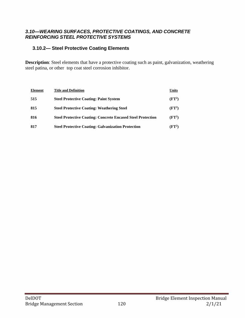
DelDOT Bridge Element Inspection Manual Bridge Management Section 120 2/1/21
3.10—WEARING SURFACES, PROTECTIVE COATINGS, AND CONCRETE REINFORCING STEEL PROTECTIVE SYSTEMS
3.10.2— Steel Protective Coating Elements
Description: Steel elements that have a protective coating such as paint, galvanization, weathering
steel patina, or other top coat steel corrosion inhibitor.
Element Title and Definition Units
515 Steel Protective Coating: Paint System (FT2)
815 Steel Protective Coating: Weathering Steel (FT2)
816 Steel Protective Coating: Concrete Encased Steel Protection (FT2)
817 Steel Protective Coating: Galvanization Protection (FT2)
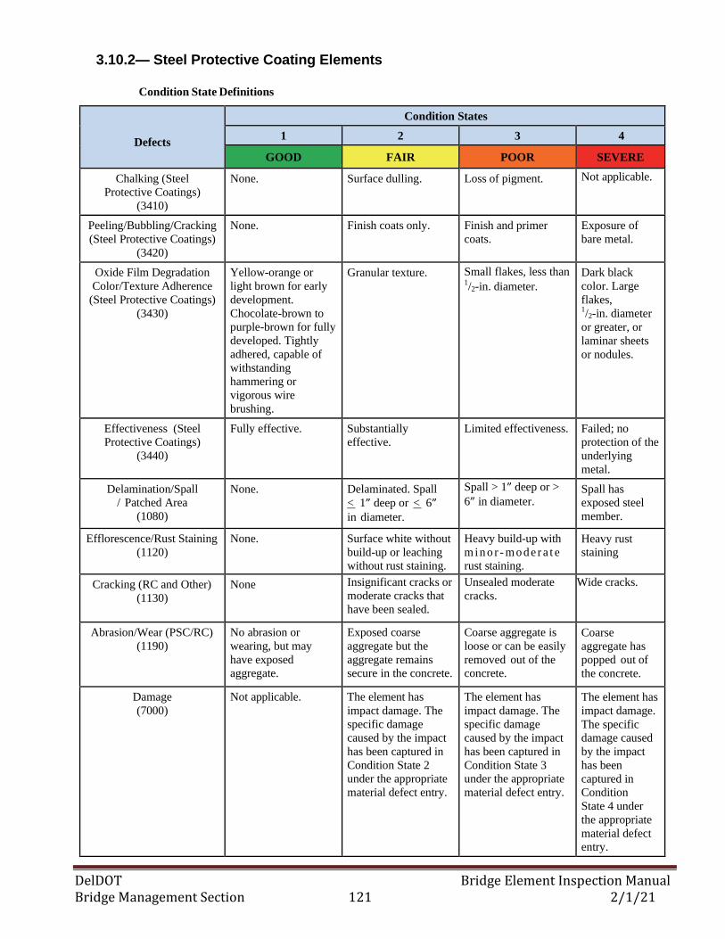
DelDOT Bridge Element Inspection Manual Bridge Management Section 121 2/1/21
3.10.2— Steel Protective Coating Elements
Condition State Definitions
Defects
Condition States
1 2 3 4
GOOD FAIR POOR SEVERE
Chalking (Steel
Protective Coatings)
(3410)
None. Surface dulling. Loss of pigment. Not applicable.
Peeling/Bubbling/Cracking
(Steel Protective Coatings)
(3420)
None. Finish coats only. Finish and primer
coats.
Exposure of
bare metal.
Oxide Film Degradation
Color/Texture Adherence
(Steel Protective Coatings)
(3430)
Yellow-orange or
light brown for early
development.
Chocolate-brown to
purple-brown for fully
developed. Tightly
adhered, capable of
withstanding
hammering or
vigorous wire
brushing.
Granular texture. Small flakes, less than 1/2-in. diameter.
Dark black
color. Large
flakes, 1/2-in. diameter
or greater, or
laminar sheets
or nodules.
Effectiveness (Steel
Protective Coatings)
(3440)
Fully effective. Substantially
effective.
Limited effectiveness. Failed; no
protection of the
underlying
metal.
Delamination/Spall
/ Patched Area
(1080)
None.
Delaminated. Spall
< 1” deep or < 6” in diameter.
Spall > 1” deep or >
6” in diameter. Spall has
exposed steel
member.
Efflorescence/Rust Staining
(1120)
None. Surface white without
build-up or leaching
without rust staining.
Heavy build-up with
min o r - mo d er a t e
rust staining.
Heavy rust
staining
Cracking (RC and Other)
(1130)
None Insignificant cracks or
moderate cracks that
have been sealed.
Unsealed moderate
cracks.
Wide cracks.
Abrasion/Wear (PSC/RC)
(1190)
No abrasion or
wearing, but may
have exposed
aggregate.
Exposed coarse
aggregate but the
aggregate remains
secure in the concrete.
Coarse aggregate is
loose or can be easily
removed out of the
concrete.
Coarse
aggregate has
popped out of
the concrete.
Damage
(7000)
Not applicable. The element has
impact damage. The
specific damage
caused by the impact
has been captured in
Condition State 2
under the appropriate
material defect entry.
The element has
impact damage. The
specific damage
caused by the impact
has been captured in
Condition State 3
under the appropriate
material defect entry.
The element has
impact damage.
The specific
damage caused
by the impact
has been
captured in
Condition
State 4 under
the appropriate
material defect
entry.
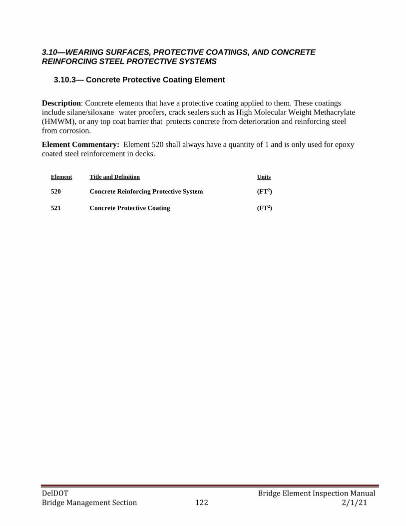
DelDOT Bridge Element Inspection Manual Bridge Management Section 122 2/1/21
3.10—WEARING SURFACES, PROTECTIVE COATINGS, AND CONCRETE REINFORCING STEEL PROTECTIVE SYSTEMS
3.10.3— Concrete Protective Coating Element
Description: Concrete elements that have a protective coating applied to them. These coatings
include silane/siloxane water proofers, crack sealers such as High Molecular Weight Methacrylate
(HMWM), or any top coat barrier that protects concrete from deterioration and reinforcing steel
from corrosion.
Element Commentary: Element 520 shall always have a quantity of 1 and is only used for epoxy
coated steel reinforcement in decks.
Element Title and Definition Units
520 Concrete Reinforcing Protective System (FT2)
521 Concrete Protective Coating (FT2)
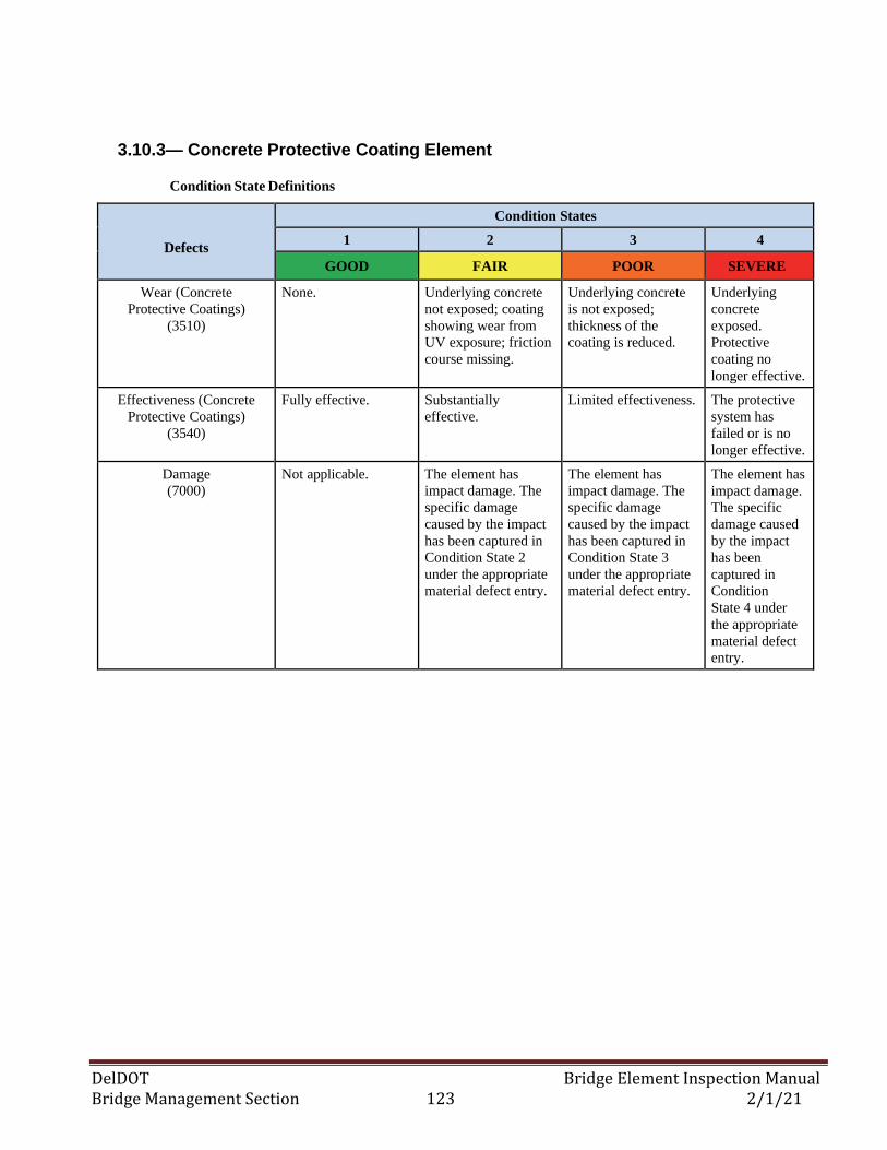
DelDOT Bridge Element Inspection Manual Bridge Management Section 123 2/1/21
3.10.3— Concrete Protective Coating Element
Condition State Definitions
Defects
Condition States
1 2 3 4
GOOD FAIR POOR SEVERE
Wear (Concrete
Protective Coatings)
(3510)
None. Underlying concrete
not exposed; coating
showing wear from
UV exposure; friction
course missing.
Underlying concrete
is not exposed;
thickness of the
coating is reduced.
Underlying
concrete
exposed.
Protective
coating no
longer effective.
Effectiveness (Concrete
Protective Coatings)
(3540)
Fully effective. Substantially
effective.
Limited effectiveness. The protective
system has
failed or is no
longer effective.
Damage
(7000)
Not applicable. The element has
impact damage. The
specific damage
caused by the impact
has been captured in
Condition State 2
under the appropriate
material defect entry.
The element has
impact damage. The
specific damage
caused by the impact
has been captured in
Condition State 3
under the appropriate
material defect entry.
The element has
impact damage.
The specific
damage caused
by the impact
has been
captured in
Condition
State 4 under
the appropriate
material defect
entry.
DelDOT Bridge Element Inspection Manual Bridge Management Section 124 2/1/21
3.11—SMART FLAG ELEMENTS 3.11.1— Soffit Smart Flag
Description: The concrete underside surface of concrete deck and slabs.
Element Commentary: Defect elements do not need to be created for the soffit element since they will
be accounted for in the concrete deck or slab defect elements. This element helps identify distress in the
under-surface of the deck or slab versus that in the top surface and will be used for assigning NBI Deck
Condition Rating and for project scoping purposes.
Element Title and Definition Units
839 Soffit (or under surface) of Concrete Deck or Slab (EA)
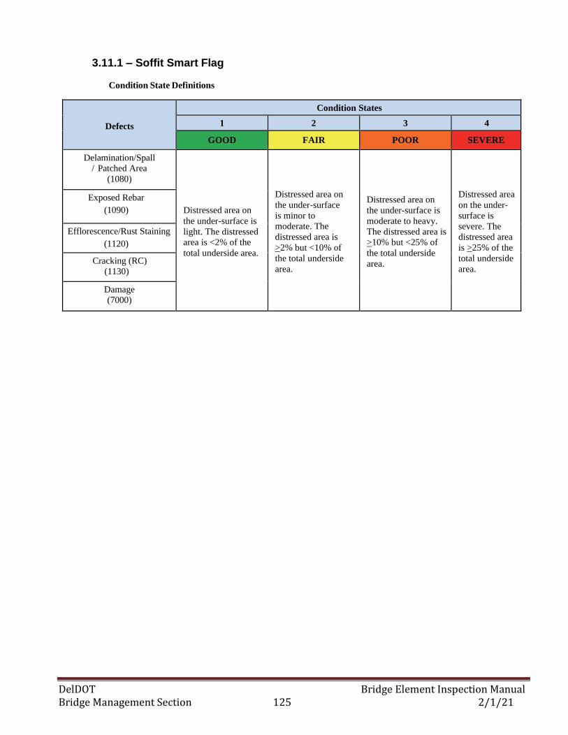
DelDOT Bridge Element Inspection Manual Bridge Management Section 125 2/1/21
3.11.1 – Soffit Smart Flag
Condition State Definitions
Defects
Condition States
1 2 3 4
GOOD FAIR POOR SEVERE
Delamination/Spall
/ Patched Area
(1080)
Distressed area on
the under-surface is
light. The distressed
area is <2% of the
total underside area.
Distressed area on
the under-surface
is minor to
moderate. The
distressed area is
>2% but <10% of
the total underside
area.
Distressed area on
the under-surface is
moderate to heavy.
The distressed area is
>10% but <25% of
the total underside
area.
Distressed area
on the under-
surface is
severe. The
distressed area
is >25% of the
total underside
area.
Exposed Rebar
(1090)
Efflorescence/Rust Staining
(1120)
Cracking (RC)
(1130)
Damage
(7000)
DelDOT Bridge Element Inspection Manual Bridge Management Section 126 2/1/21
3.11—SMART FLAG ELEMENTS
3.11.2— Erosion Smart Flag
Description: This element only applies to erosion adjacent to the structure outside of the stream and
stream bank limits.
Element Title and Definition Units
829 Erosion (EA)
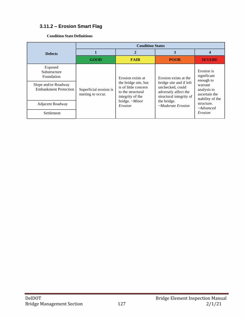
DelDOT Bridge Element Inspection Manual Bridge Management Section 127 2/1/21
3.11.2 – Erosion Smart Flag
Condition State Definitions
Defects
Condition States
1 2 3 4
GOOD FAIR POOR SEVERE
Exposed
Substructure
Foundation
Superficial erosion is
starting to occur.
Erosion exists at
the bridge site, but
is of little concern
to the structural
integrity of the
bridge. ~Minor
Erosion
Erosion exists at the
bridge site and if left
unchecked, could
adversely affect the
structural integrity of
the bridge.
~Moderate Erosion
Erosion is
significant
enough to
warrant
analysis to
ascertain the
stability of the
structure.
~Advanced
Erosion
Slope and/or Roadway
Embankment Protection
Adjacent Roadway
Settlement
DelDOT Bridge Element Inspection Manual Bridge Management Section 128 2/1/21
3.12—MOVABLE BRIDGE ELEMENTS 3.12.1— Movable Bridge Electrical System Element
Description: All electrical components associated with the operational activities for the movable bridge
structure. Does not include the electrical components for the operator’s house/facility.
Element Title and Definition Units
898 Movable Bridge Electrical System (EA)
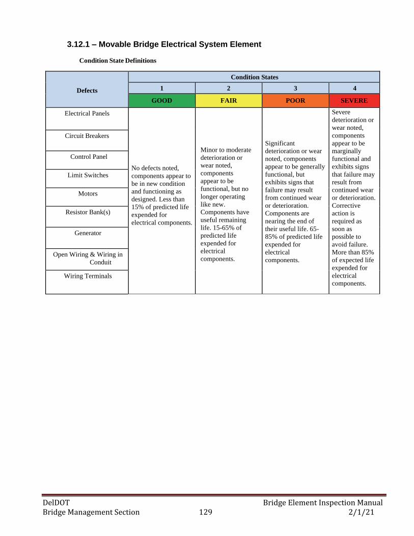
DelDOT Bridge Element Inspection Manual Bridge Management Section 129 2/1/21
3.12.1 – Movable Bridge Electrical System Element
Condition State Definitions
Defects
Condition States
1 2 3 4
GOOD FAIR POOR SEVERE
Electrical Panels
No defects noted,
components appear to
be in new condition
and functioning as
designed. Less than
15% of predicted life
expended for
electrical components.
Minor to moderate
deterioration or
wear noted,
components
appear to be
functional, but no
longer operating
like new.
Components have
useful remaining
life. 15-65% of
predicted life
expended for
electrical
components.
Significant
deterioration or wear
noted, components
appear to be generally
functional, but
exhibits signs that
failure may result
from continued wear
or deterioration.
Components are
nearing the end of
their useful life. 65-
85% of predicted life
expended for
electrical
components.
Severe
deterioration or
wear noted,
components
appear to be
marginally
functional and
exhibits signs
that failure may
result from
continued wear
or deterioration.
Corrective
action is
required as
soon as
possible to
avoid failure.
More than 85%
of expected life
expended for
electrical
components.
Circuit Breakers
Control Panel
Limit Switches
Motors
Resistor Bank(s)
Generator
Open Wiring & Wiring in
Conduit
Wiring Terminals
DelDOT Bridge Element Inspection Manual Bridge Management Section 130 2/1/21
3.12—MOVABLE BRIDGE ELEMENTS
3.12.2— Movable Bridge Mechanical System Element
Description: All mechanical components associated with the operational activities for the movable
bridge structure. Does not include the mechanical components for the operator’s house/facility.
Element Title and Definition Units
899 Movable Bridge Mechanical System (EA)
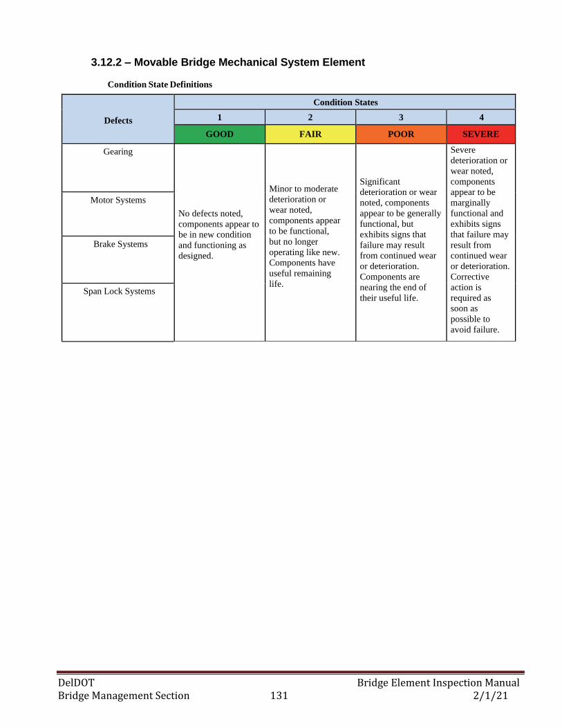
DelDOT Bridge Element Inspection Manual Bridge Management Section 131 2/1/21
3.12.2 – Movable Bridge Mechanical System Element
Condition State Definitions
Defects
Condition States
1 2 3 4
GOOD FAIR POOR SEVERE
Gearing
No defects noted,
components appear to
be in new condition
and functioning as
designed.
Minor to moderate
deterioration or
wear noted,
components appear
to be functional,
but no longer
operating like new.
Components have
useful remaining
life.
Significant
deterioration or wear
noted, components
appear to be generally
functional, but
exhibits signs that
failure may result
from continued wear
or deterioration.
Components are
nearing the end of
their useful life.
Severe
deterioration or
wear noted,
components
appear to be
marginally
functional and
exhibits signs
that failure may
result from
continued wear
or deterioration.
Corrective
action is
required as
soon as
possible to
avoid failure.
Motor Systems
Brake Systems
Span Lock Systems
DelDOT Bridge Element Inspection Manual Bridge Management Section 132 2/1/21
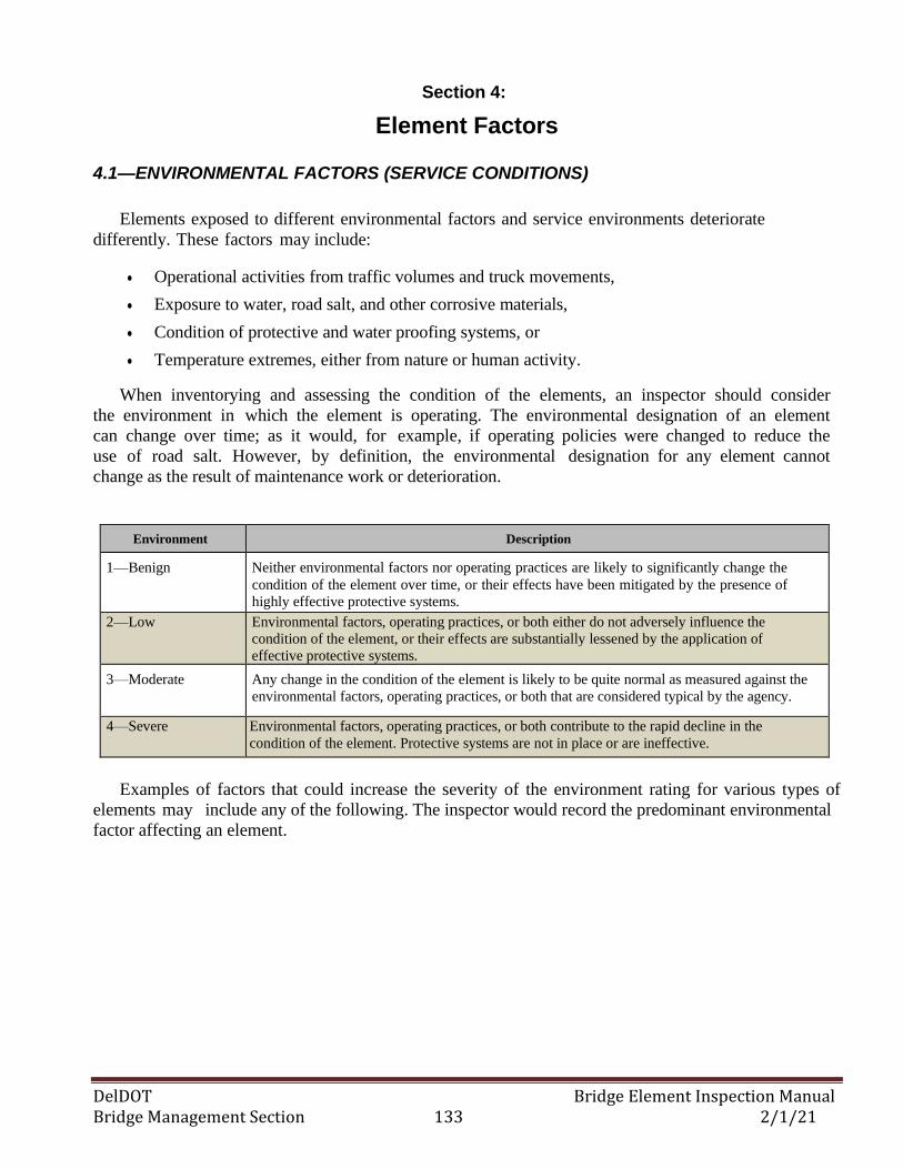
DelDOT Bridge Element Inspection Manual Bridge Management Section 133 2/1/21
Section 4:
Element Factors 4.1—ENVIRONMENTAL FACTORS (SERVICE CONDITIONS)
Elements exposed to different environmental factors and service environments deteriorate
differently. These factors may include:
• Operational activities from traffic volumes and truck movements,
• Exposure to water, road salt, and other corrosive materials,
• Condition of protective and water proofing systems, or
• Temperature extremes, either from nature or human activity.
When inventorying and assessing the condition of the elements, an inspector should consider
the environment in which the element is operating. The environmental designation of an element
can change over time; as it would, for example, if operating policies were changed to reduce the
use of road salt. However, by definition, the environmental designation for any element cannot
change as the result of maintenance work or deterioration.
Environment Description
1—Benign Neither environmental factors nor operating practices are likely to significantly change the
condition of the element over time, or their effects have been mitigated by the presence of
highly effective protective systems.
2—Low Environmental factors, operating practices, or both either do not adversely influence the
condition of the element, or their effects are substantially lessened by the application of
effective protective systems.
3—Moderate Any change in the condition of the element is likely to be quite normal as measured against the
environmental factors, operating practices, or both that are considered typical by the agency.
4—Severe Environmental factors, operating practices, or both contribute to the rapid decline in the
condition of the element. Protective systems are not in place or are ineffective.
Examples of factors that could increase the severity of the environment rating for various types of
elements may include any of the following. The inspector would record the predominant environmental
factor affecting an element.
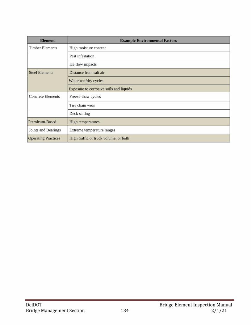
DelDOT Bridge Element Inspection Manual Bridge Management Section 134 2/1/21
Element Example Environmental Factors
Timber Elements High moisture content
Pest infestation
Ice flow impacts
Steel Elements Distance from salt air
Water wet/dry cycles
Exposure to corrosive soils and liquids
Concrete Elements Freeze-thaw cycles
Tire chain wear
Deck salting
Petroleum-Based High temperatures
Joints and Bearings Extreme temperature ranges
Operating Practices High traffic or truck volume, or both
DelDOT Bridge Element Inspection Manual Bridge Management Section 135 2/1/21
4.2—ELEMENT SCALE FACTORS Scale Factors are used to specify additional measurements for the element that can be used to adjust
project-level cost calculations. Not all elements require scale factors – inspectors should refer to the
tables in 4.2.2 to confirm which elements scale factors will need to be computed.
4.2.1—SCALE FACTOR COMPUTATIONS
All scale factors have been calculated and entered as of 12/31/14. If inspector(s) find scale factors
missing, (check past inspection by clicking onto the inspection date and selecting the previous inspection
to see if scale factors are entered), if present in the previous inspection, re-enter into the current
inspection and notify the Bridge Inspection Engineer.
All new bridge inventories and inspections where elements are added or changed and now require a scale
factor to be computed.
The inspector shall make a note under the Note Tab, Structure Notes, stating:
….NOTE: SCALE FACTORS ENTERED BY (inspectors initials) ON 00/00/00 (date of entry),
DO NOT CHANGE OR ERASE….
NOTE: The scale factors that exist in the database (current and past) are NOT TO BE CHANGED,
ERASED OR RE-CALCULATED.
To enter scale factors, click on the EDIT ELEMENT tab; enter the factor where it says scale factor to
three (3) decimal places and save.
ALL CALCULATED SCALE FACTORS THAT ARE WHOLE NUMBERS i.e. (1.000, 2.000,
6.000 etc.) SHALL BE ENTERED AS 1.001, 2.001, 6.001 etc. The reason for this is that 1.000 is the
default value within the program for all scale factors and if an element has a value of 1.000 it is assumed
that the scale factor was not computed.
Where / when available, ‘Standard Dimensions’ shall be taken from the plans as per the ‘Standard
Dimension Description’. If plans are not available or do not exist, field measurements must be taken.
For elements that are partial under ground (not visible), the maximum height dimension shall be from the
ground line to the top of the element at its highest point. Examples: Elements where footings would not
normally be visible, Abutments to top of Backwall, Wing Walls, Sheeting, MSE Walls, etc.
Standard Dimension Values are common or average element dimensions determined by Bridge
Management and shall not be changed for any reason.
Where element dimensions vary, a ‘Weighted Average’ dimension for the element shall be used in the
computation.
DelDOT Bridge Element Inspection Manual Bridge Management Section 136 2/1/21
4.2.1—SCALE FACTOR COMPUTATIONS (continued)
Example: Element #856 – R/C Sidewalk – Width (ft) with sidewalks widths = 5’ and 6’ and the lengths
are 100’ and 50’.
The weighted average width = ((5’*100’)+(6’*50’))/150’ = 5.33’
Divided by the Standard Dimension Value of 5, Scale Factor = 1.067.
For structural steel elements, calculate the surface area for each girder/beam per span (from the
‘Structural Steel Shapes Manual’). Add the square footage for each span together and divide by the total
liner footage of girders/beams to get the weighted average for the element, divide by the Value to get the
Scale Factor.
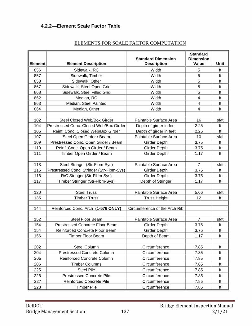
DelDOT Bridge Element Inspection Manual Bridge Management Section 137 2/1/21
4.2.2—Element Scale Factor Table
ELEMENTS FOR SCALE FACTOR COMPUTATION
Element Element Description Standard Dimension
Description
Standard Dimension
Value Unit
856 Sidewalk, RC Width 5 ft
857 Sidewalk, Timber Width 5 ft
858 Sidewalk, Other Width 5 ft
867 Sidewalk, Steel Open Grid Width 5 ft
868 Sidewalk, Steel Filled Grid Width 5 ft
862 Median, RC Width 4 ft
863 Median, Steel Painted Width 4 ft
864 Median, Other Width 4 ft
102 Steel Closed Web/Box Girder Paintable Surface Area 16 sf/ft
104 Prestressed Conc. Closed Web/Box Girder Depth of girder in feet 2.25 ft
105 Reinf. Conc. Closed Web/Box Girder Depth of girder in feet 2.25 ft
107 Steel Open Girder / Beam Paintable Surface Area 10 sf/ft
109 Prestressed Conc. Open Girder / Beam Girder Depth 3.75 ft
110 Reinf. Conc. Open Girder / Beam Girder Depth 3.75 ft
111 Timber Open Girder / Beam Girder Depth 1.17 ft
113 Steel Stringer (Str-Flbm-Sys) Paintable Surface Area 7 sf/ft
115 Prestressed Conc. Stringer (Str-Flbm-Sys) Girder Depth 3.75 ft
116 R/C Stringer (Str-Flbm-Sys) Girder Depth 3.75 ft
117 Timber Stringer (Str-Flbm-Sys) Depth of Stringer 1.17 ft
120 Steel Truss Paintable Surface Area 5.66 sf/ft
135 Timber Truss Truss Height 12 ft
144 Reinforced Conc. Arch (1-576 ONLY) Circumference of the Arch Rib
152 Steel Floor Beam Paintable Surface Area 7 sf/ft
154 Prestressed Concrete Floor Beam Girder Depth 3.75 ft
154 Reinforced Concrete Floor Beam Girder Depth 3.75 ft
156 Timber Floor Beam Depth of Beam 1.17 ft
202 Steel Column Circumference 7.85 ft
204 Prestressed Concrete Column Circumference 7.85 ft
205 Reinforced Concrete Column Circumference 7.85 ft
206 Timber Columns Circumference 7.85 ft
225 Steel Pile Circumference 7.85 ft
226 Prestressed Concrete Pile Circumference 7.85 ft
227 Reinforced Concrete Pile Circumference 7.85 ft
228 Timber Pile Circumference 7.85 ft
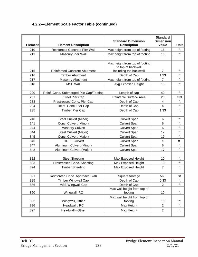
DelDOT Bridge Element Inspection Manual Bridge Management Section 138 2/1/21
4.2.2—Element Scale Factor Table (continued)
Element Element Description Standard Dimension
Description
Standard Dimension
Value Unit
210 Reinforced Concrete Pier Wall Max height from top of footing 16 ft
213 Masonry Pier Wall Max height from top of footing 16 ft
215 Reinforced Concrete Abutment
Max height from top of footing to top of backwall
including the backwall 7 ft
216 Timber Abutment Depth of Cap 1.33 ft
217 Masonry Abutment Max height from top of footing 7 ft
818 MSE Wall Avg Exposed Height 15 ft
220 Reinf. Conc. Submerged Pile Cap/Footing Length of cap 40 ft
231 Steel Pier Cap Paintable Surface Area 20 sf/ft
233 Prestressed Conc. Pier Cap Depth of Cap 4 ft
234 Reinf. Conc. Pier Cap Depth of Cap 4 ft
235 Timber Pier Cap Depth of Cap 1.33 ft
240 Steel Culvert (Minor) Culvert Span 6 ft
241 Conc. Culvert (Minor) Culvert Span 6 ft
244 Masonry Culvert Culvert Span 6 ft
844 Steel Culvert (Major) Culvert Span 17 ft
845 Conc. Culvert (Major) Culvert Span 17 ft
846 HDPE Culvert Culvert Span 5 ft
847 Aluminum Culvert (Minor) Culvert Span 6 ft
848 Aluminum Culvert (Major) Culvert Span 17 ft
822 Steel Sheeting Max Exposed Height 10 ft
823 Prestressed Conc. Sheeting Max Exposed Height 10 ft
824 Timber Sheeting Max Exposed Height 7 ft
321 Reinforced Conc. Approach Slab Square footage 560 sf
885 Timber Wingwall Cap Depth of Cap 0.33 ft
886 MSE Wingwall Cap Depth of Cap 2 ft
890 Wingwall, RC Max wall height from top of
footing 10 ft
892 Wingwall, Other Max wall height from top of
footing 10 ft
896 Headwall , RC Max Height 2 ft
897 Headwall - Other Max Height 2 ft
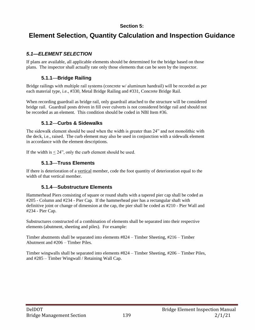
DelDOT Bridge Element Inspection Manual Bridge Management Section 139 2/1/21
Section 5:
Element Selection, Quantity Calculation and Inspection Guidance 5.1—ELEMENT SELECTION
If plans are available, all applicable elements should be determined for the bridge based on those
plans. The inspector shall actually rate only those elements that can be seen by the inspector.
5.1.1—Bridge Railing
Bridge railings with multiple rail systems (concrete w/ aluminum handrail) will be recorded as per
each material type, i.e., #330, Metal Bridge Railing and #331, Concrete Bridge Rail.
When recording guardrail as bridge rail, only guardrail attached to the structure will be considered
bridge rail. Guardrail posts driven in fill over culverts is not considered bridge rail and should not
be recorded as an element. This condition should be coded in NBI Item #36.
5.1.2—Curbs & Sidewalks
The sidewalk element should be used when the width is greater than 24” and not monolithic with
the deck, i.e., raised. The curb element may also be used in conjunction with a sidewalk element
in accordance with the element descriptions.
If the width is < 24”, only the curb element should be used.
5.1.3—Truss Elements
If there is deterioration of a vertical member, code the foot quantity of deterioration equal to the
width of that vertical member.
5.1.4—Substructure Elements
Hammerhead Piers consisting of square or round shafts with a tapered pier cap shall be coded as
#205 - Column and #234 - Pier Cap. If the hammerhead pier has a rectangular shaft with
definitive joint or change of dimension at the cap, the pier shall be coded as #210 - Pier Wall and
#234 - Pier Cap.
Substructures constructed of a combination of elements shall be separated into their respective
elements (abutment, sheeting and piles). For example:
Timber abutments shall be separated into elements #824 – Timber Sheeting, #216 – Timber
Abutment and #206 – Timber Piles.
Timber wingwalls shall be separated into elements #824 – Timber Sheeting, #206 – Timber Piles,
and #285 – Timber Wingwall / Retaining Wall Cap.
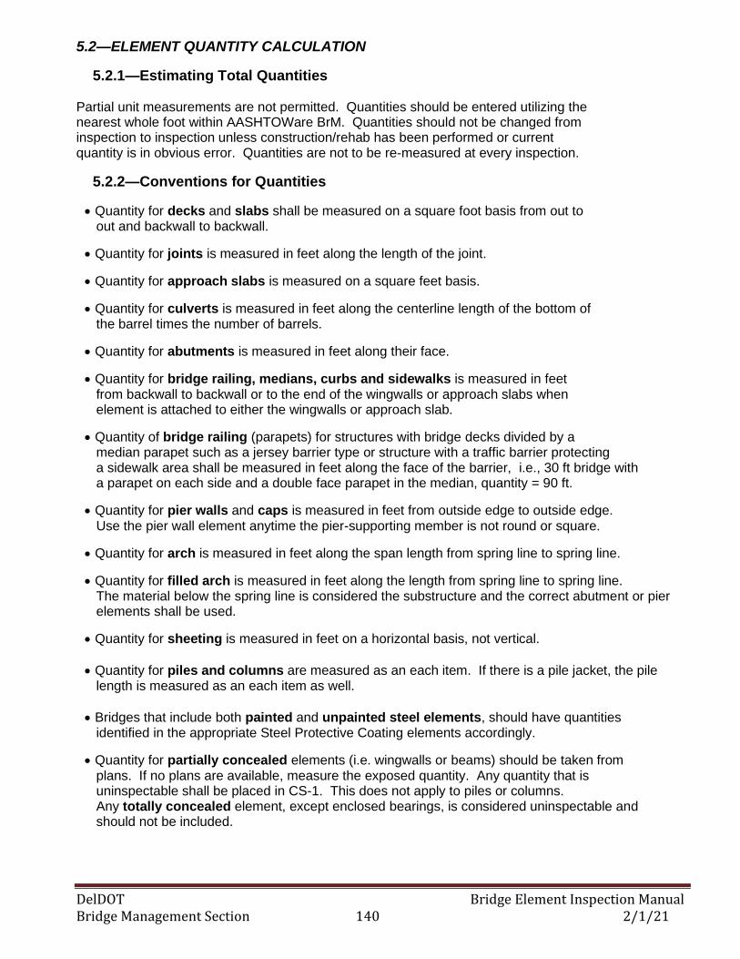
DelDOT Bridge Element Inspection Manual Bridge Management Section 140 2/1/21
5.2—ELEMENT QUANTITY CALCULATION
5.2.1—Estimating Total Quantities
Partial unit measurements are not permitted. Quantities should be entered utilizing the nearest whole foot within AASHTOWare BrM. Quantities should not be changed from inspection to inspection unless construction/rehab has been performed or current quantity is in obvious error. Quantities are not to be re-measured at every inspection.
5.2.2—Conventions for Quantities
• Quantity for decks and slabs shall be measured on a square foot basis from out to out and backwall to backwall.
• Quantity for joints is measured in feet along the length of the joint.
• Quantity for approach slabs is measured on a square feet basis.
• Quantity for culverts is measured in feet along the centerline length of the bottom of the barrel times the number of barrels.
• Quantity for abutments is measured in feet along their face.
• Quantity for bridge railing, medians, curbs and sidewalks is measured in feet from backwall to backwall or to the end of the wingwalls or approach slabs when element is attached to either the wingwalls or approach slab.
• Quantity of bridge railing (parapets) for structures with bridge decks divided by a median parapet such as a jersey barrier type or structure with a traffic barrier protecting a sidewalk area shall be measured in feet along the face of the barrier, i.e., 30 ft bridge with a parapet on each side and a double face parapet in the median, quantity = 90 ft.
• Quantity for pier walls and caps is measured in feet from outside edge to outside edge. Use the pier wall element anytime the pier-supporting member is not round or square.
• Quantity for arch is measured in feet along the span length from spring line to spring line.
• Quantity for filled arch is measured in feet along the length from spring line to spring line. The material below the spring line is considered the substructure and the correct abutment or pier elements shall be used.
• Quantity for sheeting is measured in feet on a horizontal basis, not vertical.
• Quantity for piles and columns are measured as an each item. If there is a pile jacket, the pile length is measured as an each item as well.
• Bridges that include both painted and unpainted steel elements, should have quantities identified in the appropriate Steel Protective Coating elements accordingly.
• Quantity for partially concealed elements (i.e. wingwalls or beams) should be taken from plans. If no plans are available, measure the exposed quantity. Any quantity that is uninspectable shall be placed in CS-1. This does not apply to piles or columns. Any totally concealed element, except enclosed bearings, is considered uninspectable and should not be included.
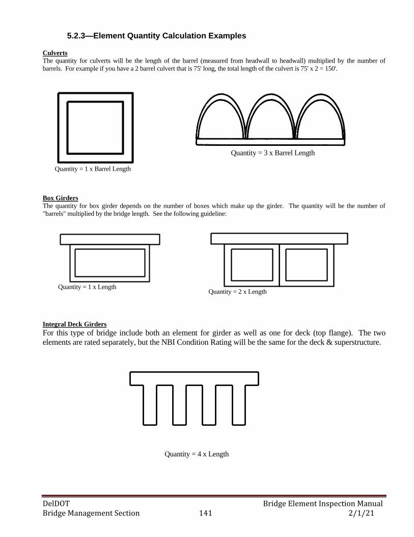
DelDOT Bridge Element Inspection Manual Bridge Management Section 141 2/1/21
Quantity = 3 x Barrel Length
5.2.3—Element Quantity Calculation Examples
Culverts The quantity for culverts will be the length of the barrel (measured from headwall to headwall) multiplied by the number of
barrels. For example if you have a 2 barrel culvert that is 75' long, the total length of the culvert is 75' x 2 = 150'.
Box Girders
The quantity for box girder depends on the number of boxes which make up the girder. The quantity will be the number of
"barrels" multiplied by the bridge length. See the following guideline:
Integral Deck Girders For this type of bridge include both an element for girder as well as one for deck (top flange). The two
elements are rated separately, but the NBI Condition Rating will be the same for the deck & superstructure.
Quantity = 4 x Length
Quantity = 1 x Barrel Length
Quantity = 1 x Length
Quantity = 2 x Length
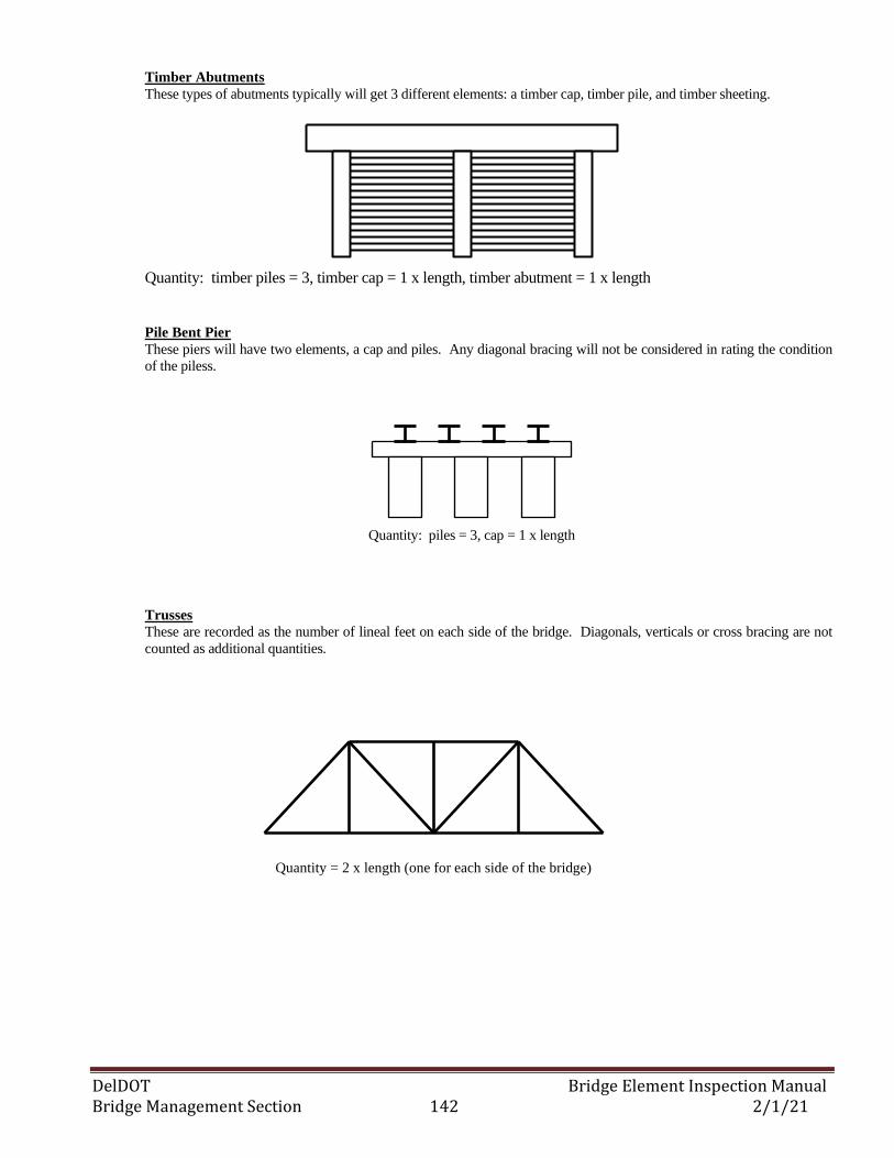
DelDOT Bridge Element Inspection Manual Bridge Management Section 142 2/1/21
Timber Abutments
These types of abutments typically will get 3 different elements: a timber cap, timber pile, and timber sheeting.
Quantity: timber piles = 3, timber cap = 1 x length, timber abutment = 1 x length
Pile Bent Pier
These piers will have two elements, a cap and piles. Any diagonal bracing will not be considered in rating the condition
of the piless.
Trusses
These are recorded as the number of lineal feet on each side of the bridge. Diagonals, verticals or cross bracing are not
counted as additional quantities.
Quantity: piles = 3, cap = 1 x length
Quantity = 2 x length (one for each side of the bridge)
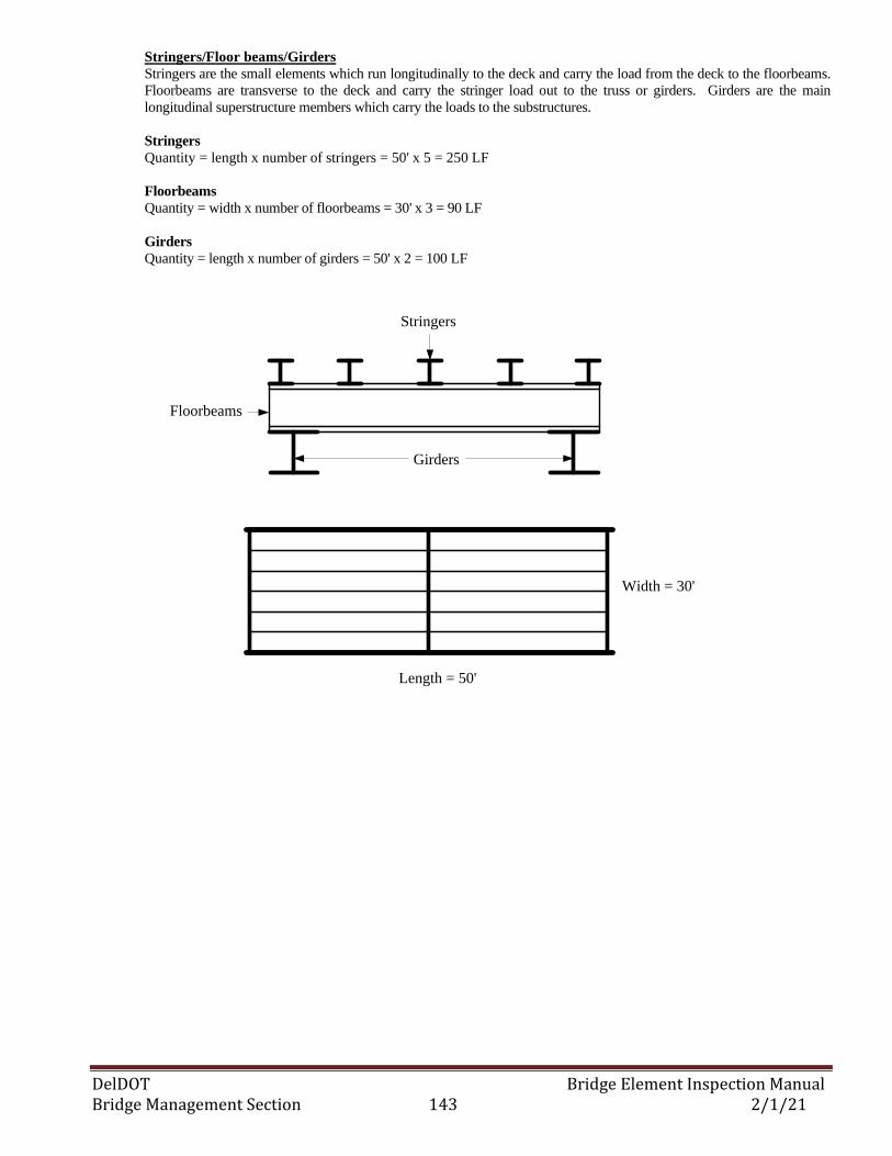
DelDOT Bridge Element Inspection Manual Bridge Management Section 143 2/1/21
Stringers/Floor beams/Girders Stringers are the small elements which run longitudinally to the deck and carry the load from the deck to the floorbeams.
Floorbeams are transverse to the deck and carry the stringer load out to the truss or girders. Girders are the main
longitudinal superstructure members which carry the loads to the substructures.
Stringers
Quantity = length x number of stringers = 50' x 5 = 250 LF
Floorbeams
Quantity = width x number of floorbeams = 30' x 3 = 90 LF
Girders
Quantity = length x number of girders = 50' x 2 = 100 LF
Stringers
Floorbeams
Girders
Length = 50'
Width = 30'
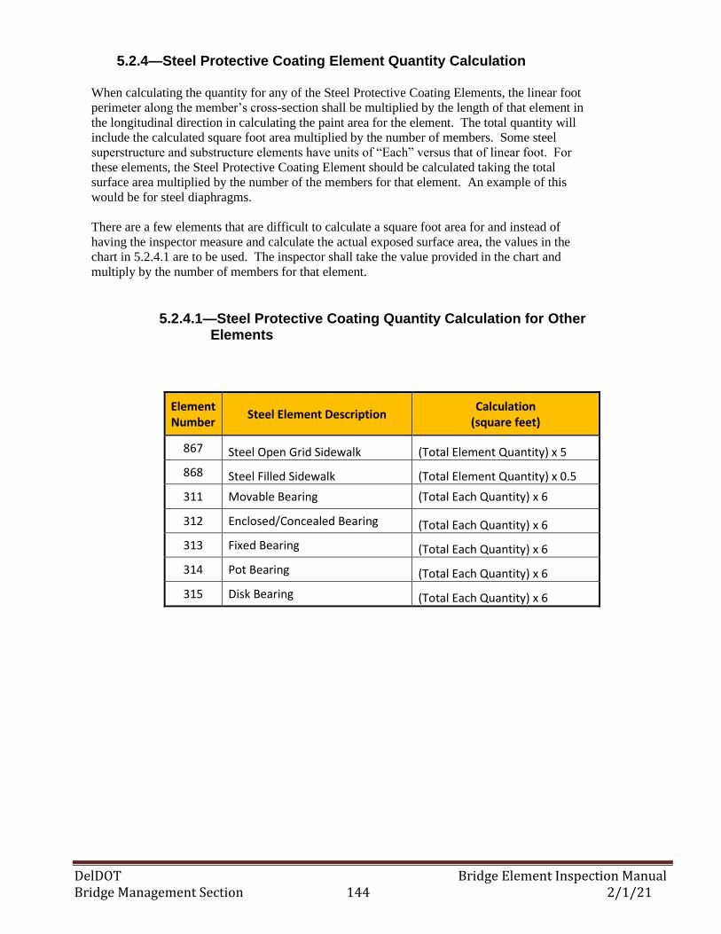
DelDOT Bridge Element Inspection Manual Bridge Management Section 144 2/1/21
5.2.4—Steel Protective Coating Element Quantity Calculation
When calculating the quantity for any of the Steel Protective Coating Elements, the linear foot
perimeter along the member’s cross-section shall be multiplied by the length of that element in
the longitudinal direction in calculating the paint area for the element. The total quantity will
include the calculated square foot area multiplied by the number of members. Some steel
superstructure and substructure elements have units of “Each” versus that of linear foot. For
these elements, the Steel Protective Coating Element should be calculated taking the total
surface area multiplied by the number of the members for that element. An example of this
would be for steel diaphragms.
There are a few elements that are difficult to calculate a square foot area for and instead of
having the inspector measure and calculate the actual exposed surface area, the values in the
chart in 5.2.4.1 are to be used. The inspector shall take the value provided in the chart and
multiply by the number of members for that element.
5.2.4.1—Steel Protective Coating Quantity Calculation for Other Elements
Element Number
Steel Element Description Calculation
(square feet)
867 Steel Open Grid Sidewalk (Total Element Quantity) x 5
868 Steel Filled Sidewalk (Total Element Quantity) x 0.5
311 Movable Bearing (Total Each Quantity) x 6
312 Enclosed/Concealed Bearing (Total Each Quantity) x 6
313 Fixed Bearing (Total Each Quantity) x 6
314 Pot Bearing (Total Each Quantity) x 6
315 Disk Bearing (Total Each Quantity) x 6
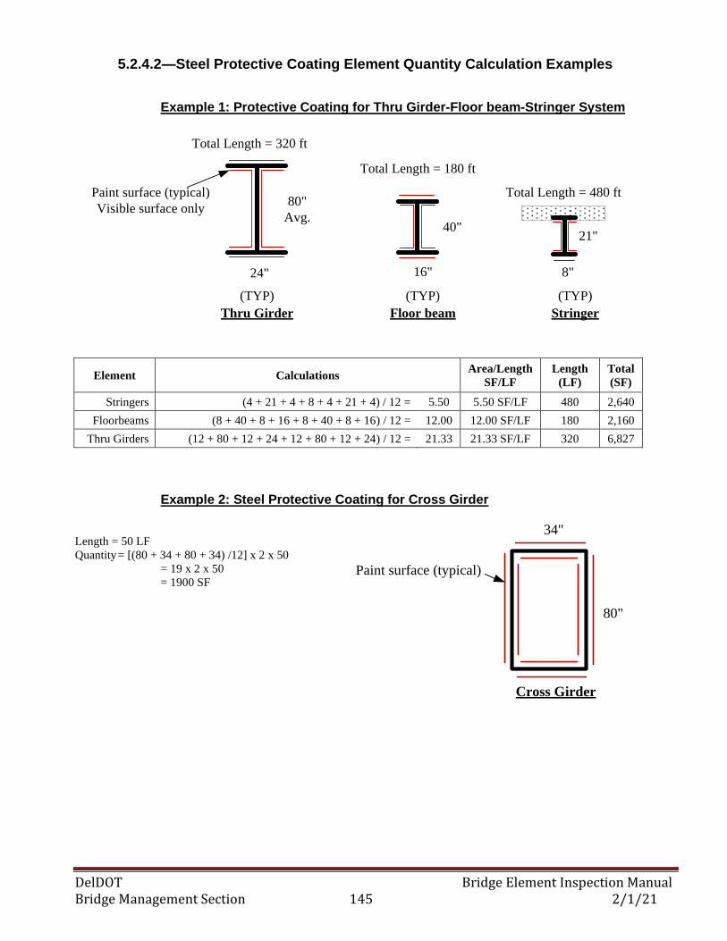
DelDOT Bridge Element Inspection Manual Bridge Management Section 145 2/1/21
5.2.4.2—Steel Protective Coating Element Quantity Calculation Examples
Example 1: Protective Coating for Thru Girder-Floor beam-Stringer System
16"
40"
24"
80"
Avg.
8"
21"
Paint surface (typical)
Visible surface only
(TYP) (TYP) (TYP)
Thru Girder Floor beam Stringer
Total Length = 320 ft
Total Length = 480 ft
Total Length = 180 ft
Element Calculations Area/Length
SF/LF
Length
(LF)
Total
(SF)
Stringers (4 + 21 + 4 + 8 + 4 + 21 + 4) / 12 = 5.50 5.50 SF/LF 480 2,640
Floorbeams (8 + 40 + 8 + 16 + 8 + 40 + 8 + 16) / 12 = 12.00 12.00 SF/LF 180 2,160
Thru Girders (12 + 80 + 12 + 24 + 12 + 80 + 12 + 24) / 12 = 21.33 21.33 SF/LF 320 6,827
Example 2: Steel Protective Coating for Cross Girder
Length = 50 LF
Quantity = [(80 + 34 + 80 + 34) /12] x 2 x 50
= 19 x 2 x 50
= 1900 SF
80"
Cross Girder
34"
Paint surface (typical)
DelDOT Bridge Element Inspection Manual Bridge Management Section 146 2/1/21
5.3—INSPECTION GUIDANCE
5.3.1—General
The inspector shall review prior bridge inspection reports to verify that all element numbers
and quantities are accurate according to previously stated guidelines. Current underwater
inspections shall be reviewed and utilized when rating substructure elements.
5.3.2—Inspection Orientation
Orientation shall be stations ahead (from any existing plans) with left elements, such as
girders, being numbered 1. If plans are not available, match the previous inspection
orientation. If no previous inspection or plans are available, inspection orientation shall
be west to east or south to north.
5.3.3—Multi-Span Orientation
Element Documentation for multi-span bridges on span-by-span basis
Span #1 should include:
1. The deck element and any overlays and/or defects.
2. Superstructure elements including the bearings supporting that span. Joint at
abutment and pier #1
3. The substructure elements including the abutment and first pier.
Span #2 and remaining spans should include:
1. Superstructure elements including the bearings supporting that span. Joint at pier
or abutment #2.
2. Substructure elements including the next pier or abutment if last span.
Element Documentation for multi-span bridges, with buried spans, on a span-by-
span basis
First span should include:
1. The deck element (whole deck quantity) and any smart flags.
2. Any visible elements in the format as documented above.
Subsequent spans should include:
1. Any visible elements in the format documented above.
Note: For bridges with buried spans, the abutment may be placed in the span in which it
is visible. A substructure element is considered a pier if it can be inspected on all sides
otherwise it is an abutment.
Example: 3-span bridge, first two spans buried, third span visible with pier visible on
one side only and an abutment.
Span 1 elements: Deck, Smart Flags, Railing, Joints, other visible elements
Span 2 elements: Railing, Joints, other visible elements
Span 3 elements: Two Abutments, Bearings, Beams, Railing, Joints, other visible
elements
DelDOT Bridge Element Inspection Manual Bridge Management Section 147 2/1/21
5.3.4—Element Condition State Assignment Guidance
All elements have four condition state options that the bridge inspection team may choose based on the
type and severity of deterioration observed. The list below provides a general description of the types of
defects associated with each condition state.
- Condition State 1 may include superficial type of defects or no defects at all.
- Condition State 2 includes minor defects or minor-moderate deterioration.
- Condition State 3 includes moderate – heavy deterioration.
- Condition State 4 includes advanced deterioration or defects that warrant a structural review. The
structural review may consist of structural analysis computations or engineering judgment.
All primary and secondary structural components that are assigned any quantity in a Condition State 4 will
require review by DelDOT’s Bridge Inspection Engineer and/or Bridge Management Engineer. Upon
completion of the structural review, the Condition State may be reduced to that of a Condition State 3 if
the review shows that the load carrying capacity of the bridge has not been affected. The load carrying
capacity is typically identified as whether or not the bridge needs to be posted for any of the Delaware
Legal Loads.
5.3.5—Concrete Crack Size Definitions
Reinforced Concrete Prestressed Concrete
Insignificant - < 1/16” Insignificant - < 0.004 “
Moderate - > 1/16 “ – 1/4 “ Moderate - > 0 .004 “ - 0.009 “
Wide - > 1/4” Wide - >.009 “
Note: Crack dimensions for prestressed concrete apply to cracks that are perpendicular to
prestressing. For cracks that are parallel to prestressing, refer to crack dimensions for
reinforced concrete.
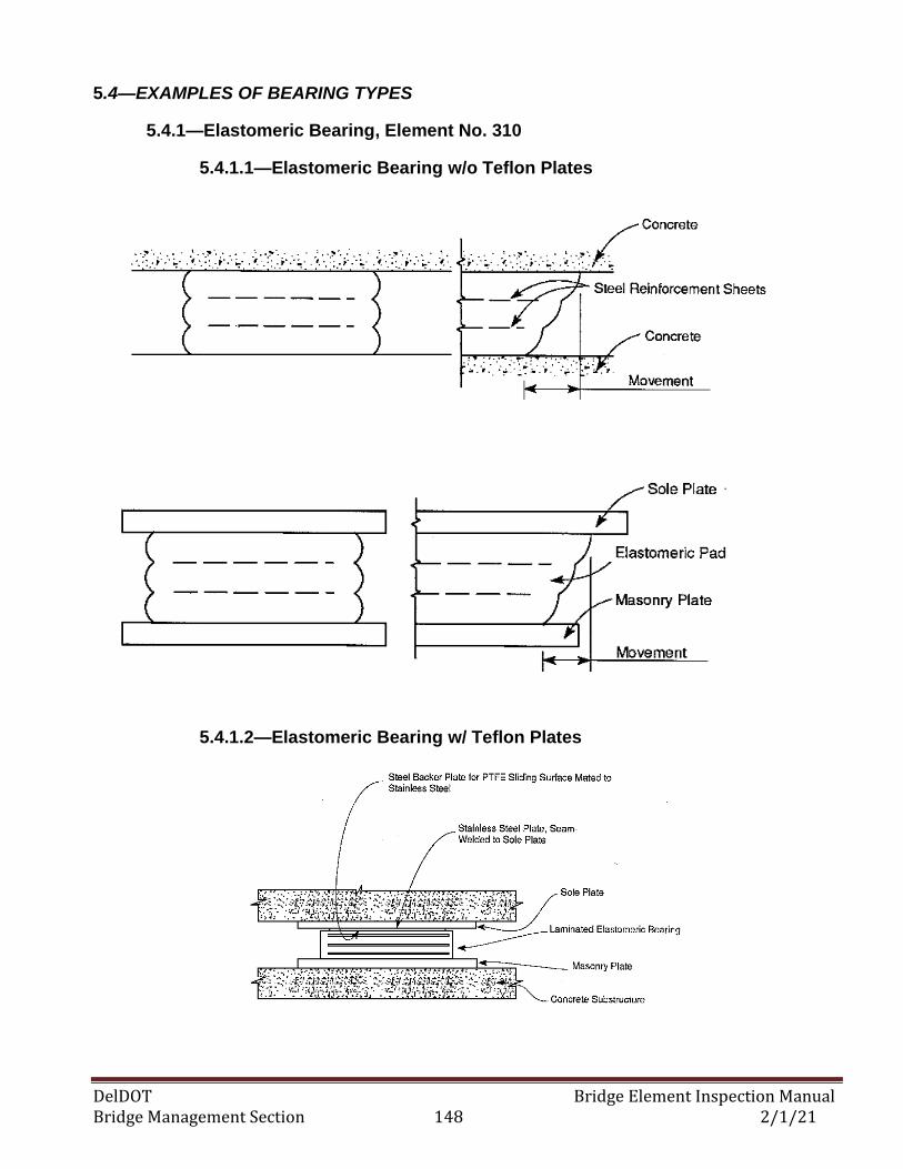
DelDOT Bridge Element Inspection Manual Bridge Management Section 148 2/1/21
5.4—EXAMPLES OF BEARING TYPES
5.4.1—Elastomeric Bearing, Element No. 310
5.4.1.1—Elastomeric Bearing w/o Teflon Plates
5.4.1.2—Elastomeric Bearing w/ Teflon Plates
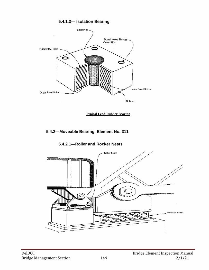
DelDOT Bridge Element Inspection Manual Bridge Management Section 149 2/1/21
5.4.1.3— Isolation Bearing
Typical Lead-Rubber Bearing
5.4.2—Moveable Bearing, Element No. 311
5.4.2.1—Roller and Rocker Nests
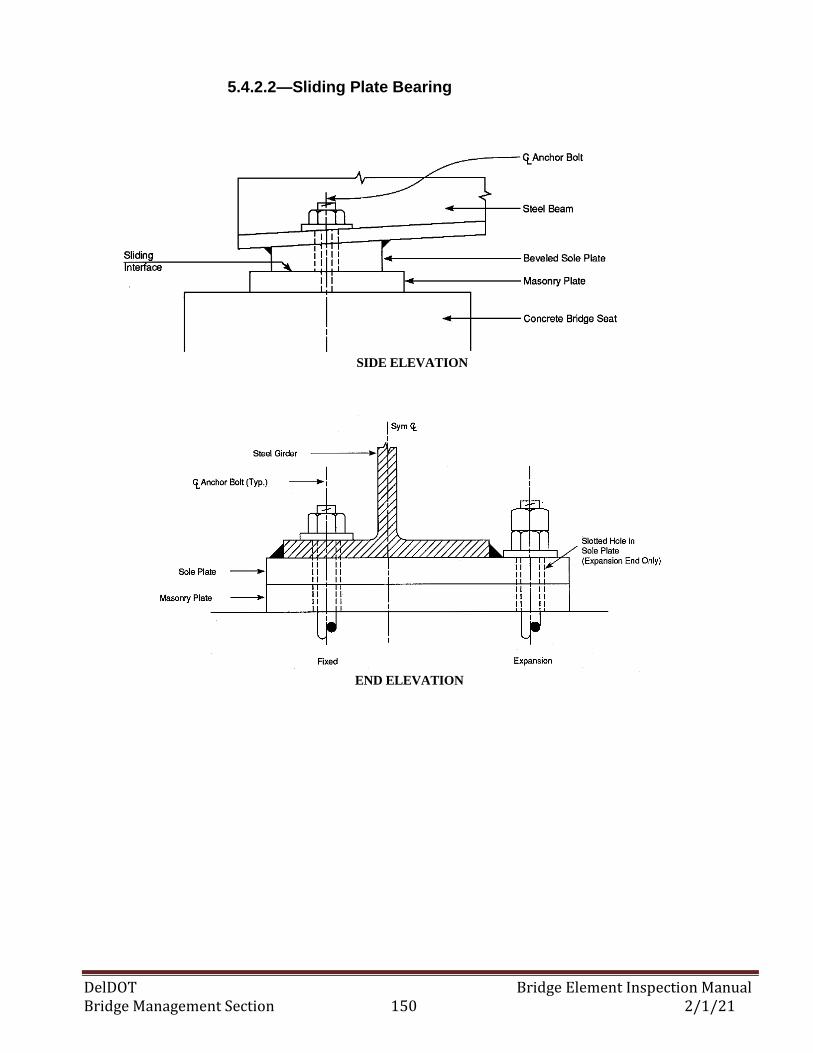
DelDOT Bridge Element Inspection Manual Bridge Management Section 150 2/1/21
5.4.2.2—Sliding Plate Bearing
SIDE ELEVATION
END ELEVATION
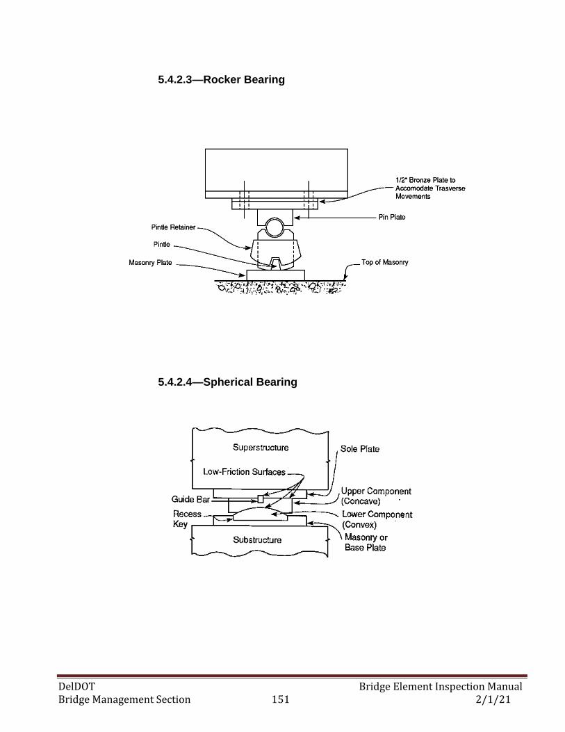
DelDOT Bridge Element Inspection Manual Bridge Management Section 151 2/1/21
5.4.2.3—Rocker Bearing
5.4.2.4—Spherical Bearing
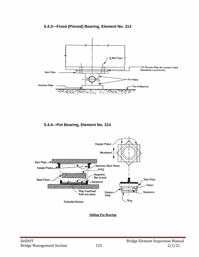
DelDOT Bridge Element Inspection Manual Bridge Management Section 152 2/1/21
5.4.3—Fixed (Pinned) Bearing, Element No. 313
5.4.4—Pot Bearing, Element No. 314
Sliding Pot Bearing
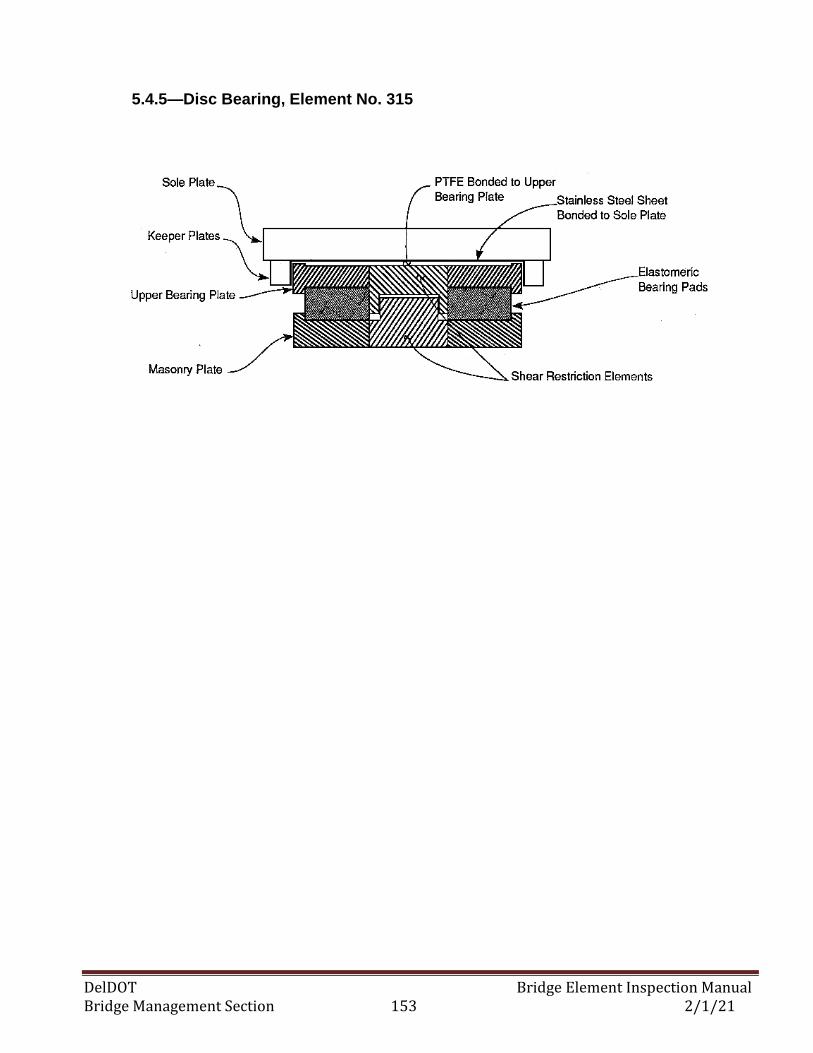
DelDOT Bridge Element Inspection Manual Bridge Management Section 153 2/1/21
5.4.5—Disc Bearing, Element No. 315
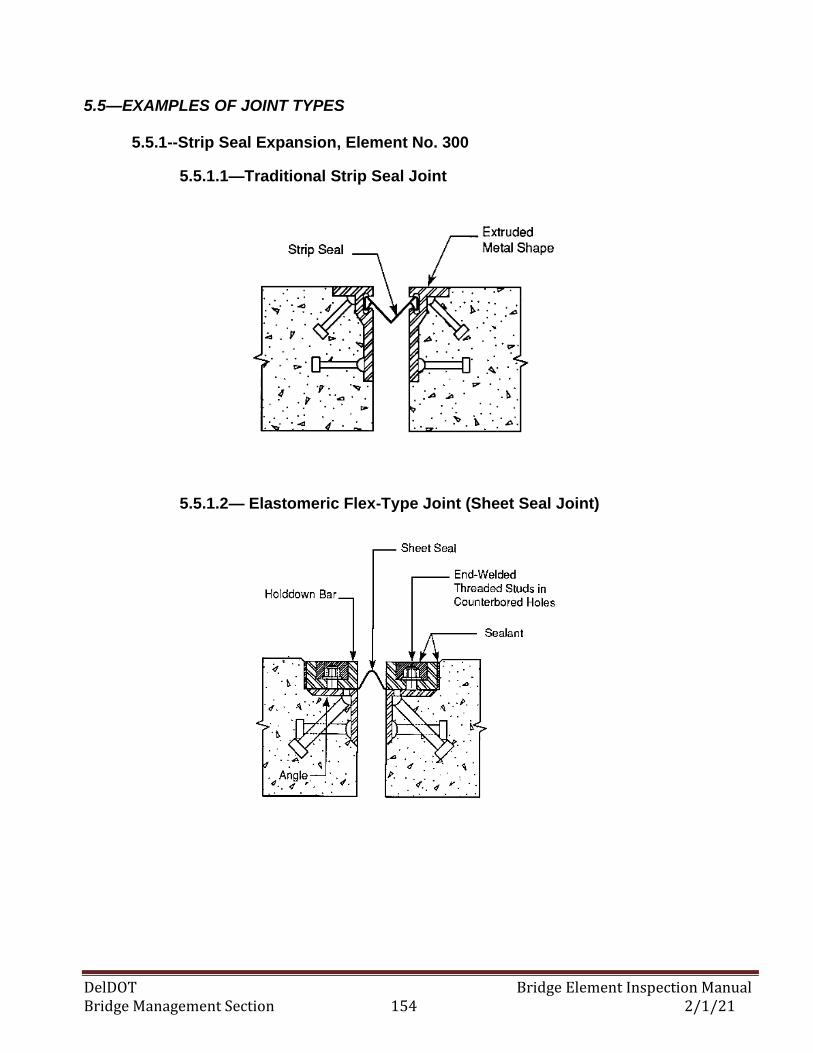
DelDOT Bridge Element Inspection Manual Bridge Management Section 154 2/1/21
5.5—EXAMPLES OF JOINT TYPES
5.5.1--Strip Seal Expansion, Element No. 300
5.5.1.1—Traditional Strip Seal Joint
5.5.1.2— Elastomeric Flex-Type Joint (Sheet Seal Joint)
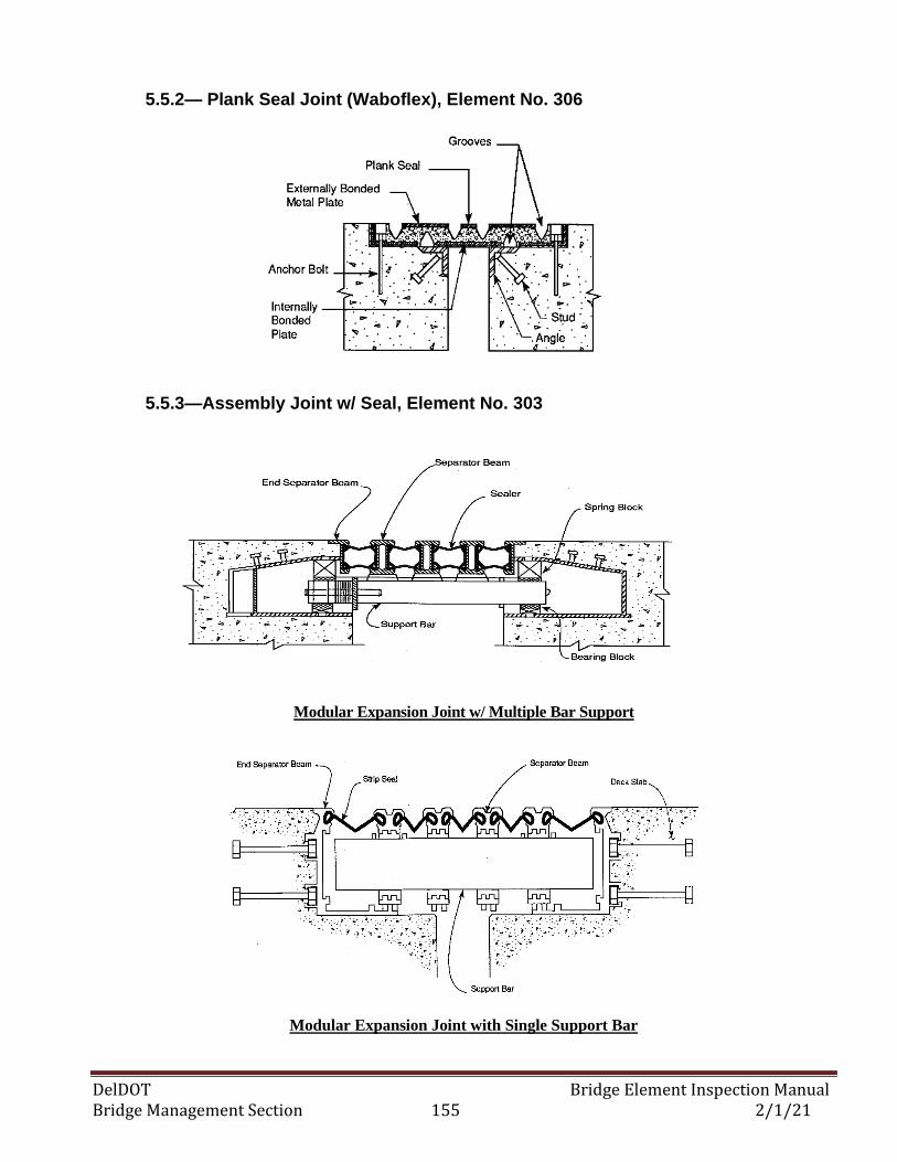
DelDOT Bridge Element Inspection Manual Bridge Management Section 155 2/1/21
5.5.2— Plank Seal Joint (Waboflex), Element No. 306
5.5.3—Assembly Joint w/ Seal, Element No. 303
Modular Expansion Joint w/ Multiple Bar Support
Modular Expansion Joint with Single Support Bar
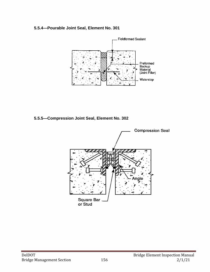
DelDOT Bridge Element Inspection Manual Bridge Management Section 156 2/1/21
5.5.4—Pourable Joint Seal, Element No. 301
5.5.5—Compression Joint Seal, Element No. 302
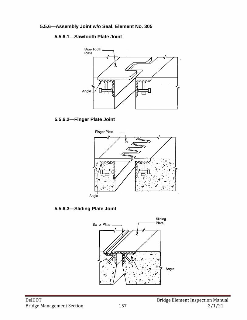
DelDOT Bridge Element Inspection Manual Bridge Management Section 157 2/1/21
5.5.6—Assembly Joint w/o Seal, Element No. 305
5.5.6.1—Sawtooth Plate Joint
5.5.6.2—Finger Plate Joint
5.5.6.3—Sliding Plate Joint
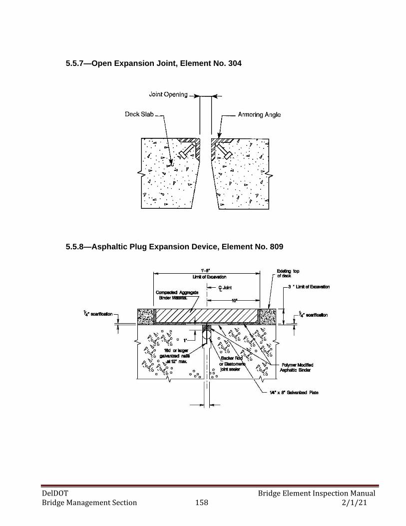
DelDOT Bridge Element Inspection Manual Bridge Management Section 158 2/1/21
5.5.7—Open Expansion Joint, Element No. 304
5.5.8—Asphaltic Plug Expansion Device, Element No. 809
DelDOT Bridge Element Inspection Manual Bridge Management Section 159 2/1/21
APPENDIX A:
AGENCY-DEFINED ELEMENTS (ADEs)
This manual was developed with the understanding that agencies may have elements in their
inventory that are not included in the defined element set. An unlimited number of agency elements
can be defined as necessary, providing that they conform to this manual.
Agency elements fall into three main categories:
• Subsets of defined National Bridge Elements,
• Subsets of defined Bridge Management Elements, and
• Elements that are entirely independent of the defined elements.
A1—AGENCY-DEFINED SUBSETS OF THE NATIONAL BRIDGE ELEMENTS
The National Bridge Elements (NBE’s) represent the primary structural components of bridges
and are of national concern for safety. The NBE elements are intended to form an element basis
for bridge condition assessment in the National Bridge Inventory (NBI). Due to the higher purpose
for these NBEs, the flexibility for an agency to customize them is limited. An agency is permitted to
create NBE sub-elements providing that the sub-elements can be aggregated back together for NBI
submission. In all cases, the element condition states are fixed at four states and the specific
condition state and defect criteria must remain consistent between the NBE and all agency-developed
NBE sub-elements. For example, many agencies have developed elements to capture the quantity and
condition of their “beam ends.” This agency-developed element isolates the area around joints or
hinges to capture the rapid deterioration that may occur in this area. Since the beam element itself is
an NBE, this agency-developed sub-element would need to inherit all of the language
characteristics of the encompassing NBE. In this example, the agency will simply subdivide the element
quantity between two items that both share the same language. Combining the NBE beam element
and the agency-developed “beam ends” together is simple addition and would permit consistent
reporting of the quantity and condition distribution of this item to the NBI.
A2—AGENCY-DEFINED SUBSETS OF THE BRIDGE MANAGEMENT ELEMENTS
Agency-developed elements that are not a subset of an NBE have considerably more flexibility in
customization. The Bridge Management Elements (BME’s) represent many components of bridges
that require preservation but are not primary structural members. These elements include joints,
wearing surfaces, protective coatings, and deck protection systems. These elements as a class are
defined to provide a sound basis for bridge management. In order to identify these additional agency
elements, the number range of 800 and above has been used in this manual.
This manual has defined a set of basic BME's along with elements specific to our agency that
provides more detail in certain areas. For example, DelDOT has defined additional wearing surfaces
typically used in our bridge inventory into their own wearing surface elements in order to track
performance and recognize cost differences for actions. In this example, these detailed wearing surface
elements are considered sub-elements of the general BME for wearing surfaces. For this
DelDOT Bridge Element Inspection Manual Bridge Management Section 160 2/1/21
wearing surface example, it is still required to define only four condition states following the good,
fair, poor, and severe convention.
A3—INDEPENDENT AGENCY-DEFINED ELEMENTS
DelDOT has identified a need to develop completely independent custom elements that are not a
subset or derivative of an NBE or BME. These custom elements provide flexibility; these elements
are not intended to be reported at a national level, nor will they be expected to be rolled up into any
element with defined condition state language in this manual. These elements are available for our
agency utilizing a BMS to track elements unique to our inventory, such as movable bridge
components, or to capture specific performance aspects of bridges. Independent agency-defined
elements may or may not have defined feasible actions or defined deterioration, and don’t follow any
standard condition state or defect language. These are free-form elements that are only limited by the
number of required condition states (four).
Independent agency elements have been created to track maintenance items that our agency wishes
to capture during the inspection process. Items such as the condition of drains, roadway slope, etc.
have been developed into elements that are not associated with deterioration but potentially have
feasible actions.
Independent agency-developed elements have also been created to capture the components and
condition of ancillary structures that our agency is required to inspect. These elements exist side by
side with the bridge elements and have been defined with deterioration models or feasible actions.
Custom element definitions provide a ready-made framework for capturing items such as retaining
walls, median barriers and fender/dolphin systems within our agency’s BMS.
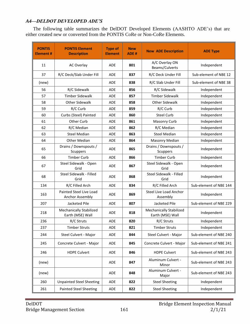
DelDOT Bridge Element Inspection Manual Bridge Management Section 161 2/1/21
A4—DELDOT DEVELOPED ADE’S
The following table summarizes the DelDOT Developed Elements (AASHTO ADE’s) that are
either created new or converted from the PONTIS CoRe or Non-CoRe Elements.
PONTIS Element #
PONTIS Element Description
Type of Element
New ADE #
New ADE Description ADE Type
11 AC Overlay ADE 801 A/C Overlay ON Beams/Culverts
Independent
37 R/C Deck/Slab Under Fill ADE 837 R/C Deck Under Fill Sub-element of NBE 12
(new) ADE 838 R/C Slab Under Fill Sub-element of NBE 38
56 R/C Sidewalk ADE 856 R/C Sidewalk Independent
57 Timber Sidewalk ADE 857 Timber Sidewalk Independent
58 Other Sidewalk ADE 858 Other Sidewalk Independent
59 R/C Curb ADE 859 R/C Curb Independent
60 Curbs (Steel) Painted ADE 860 Steel Curb Independent
61 Other Curb ADE 861 Masonry Curb Independent
62 R/C Median ADE 862 R/C Median Independent
63 Steel Median ADE 863 Steel Median Independent
64 Other Median ADE 864 Masonry Median Independent
65 Drains / Downspouts /
Scuppers ADE 865
Drains / Downspouts / Scuppers
Independent
66 Timber Curb ADE 866 Timber Curb Independent
67 Steel Sidewalk - Open
Grid ADE 867
Steel Sidewalk - Open Grid
Independent
68 Steel Sidewalk - Filled
Grid ADE 868
Steel Sidewalk - Filled Grid
Independent
134 R/C Filled Arch ADE 834 R/C Filled Arch Sub-element of NBE 144
163 Painted Steel Live Load
Anchor Assembly ADE 869
Steel Live Load Anchor Assembly
Independent
207 Jacketed Pile ADE 807 Jacketed Pile Sub-element of NBE 229
218 Mechanically Stabilized
Earth (MSE) Wall ADE 818
Mechanically Stabilized Earth (MSE) Wall
Independent
236 R/C Struts ADE 820 R/C Struts Independent
237 Timber Struts ADE 821 Timber Struts Independent
244 Steel Culvert - Major ADE 844 Steel Culvert - Major Sub-element of NBE 240
245 Concrete Culvert - Major ADE 845 Concrete Culvert - Major Sub-element of NBE 241
246 HDPE Culvert ADE 846 HDPE Culvert Sub-element of NBE 243
(new) ADE 847 Aluminum Culvert -
Minor Sub-element of NBE 243
(new) ADE 848 Aluminum Culvert -
Major Sub-element of NBE 243
260 Unpainted Steel Sheeting ADE 822 Steel Sheeting Independent
261 Painted Steel Sheeting ADE 822 Steel Sheeting Independent
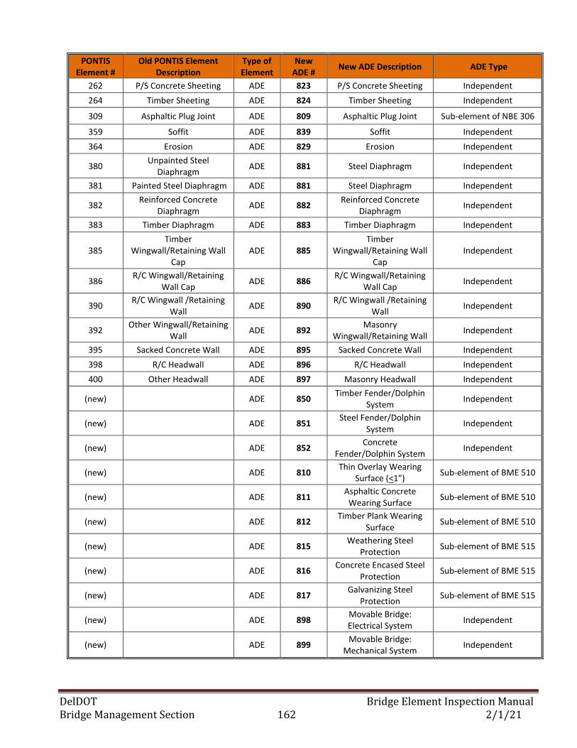
DelDOT Bridge Element Inspection Manual Bridge Management Section 162 2/1/21
PONTIS Element #
Old PONTIS Element Description
Type of Element
New ADE #
New ADE Description ADE Type
262 P/S Concrete Sheeting ADE 823 P/S Concrete Sheeting Independent
264 Timber Sheeting ADE 824 Timber Sheeting Independent
309 Asphaltic Plug Joint ADE 809 Asphaltic Plug Joint Sub-element of NBE 306
359 Soffit ADE 839 Soffit Independent
364 Erosion ADE 829 Erosion Independent
380 Unpainted Steel
Diaphragm ADE 881 Steel Diaphragm Independent
381 Painted Steel Diaphragm ADE 881 Steel Diaphragm Independent
382 Reinforced Concrete
Diaphragm ADE 882
Reinforced Concrete Diaphragm
Independent
383 Timber Diaphragm ADE 883 Timber Diaphragm Independent
385 Timber
Wingwall/Retaining Wall Cap
ADE 885 Timber
Wingwall/Retaining Wall Cap
Independent
386 R/C Wingwall/Retaining
Wall Cap ADE 886
R/C Wingwall/Retaining Wall Cap
Independent
390 R/C Wingwall /Retaining
Wall ADE 890
R/C Wingwall /Retaining Wall
Independent
392 Other Wingwall/Retaining
Wall ADE 892
Masonry Wingwall/Retaining Wall
Independent
395 Sacked Concrete Wall ADE 895 Sacked Concrete Wall Independent
398 R/C Headwall ADE 896 R/C Headwall Independent
400 Other Headwall ADE 897 Masonry Headwall Independent
(new) ADE 850 Timber Fender/Dolphin
System Independent
(new) ADE 851 Steel Fender/Dolphin
System Independent
(new) ADE 852 Concrete
Fender/Dolphin System Independent
(new) ADE 810 Thin Overlay Wearing
Surface (<1") Sub-element of BME 510
(new) ADE 811 Asphaltic Concrete
Wearing Surface Sub-element of BME 510
(new) ADE 812 Timber Plank Wearing
Surface Sub-element of BME 510
(new) ADE 815 Weathering Steel
Protection Sub-element of BME 515
(new) ADE 816 Concrete Encased Steel
Protection Sub-element of BME 515
(new) ADE 817 Galvanizing Steel
Protection Sub-element of BME 515
(new) ADE 898 Movable Bridge: Electrical System
Independent
(new) ADE 899 Movable Bridge:
Mechanical System Independent
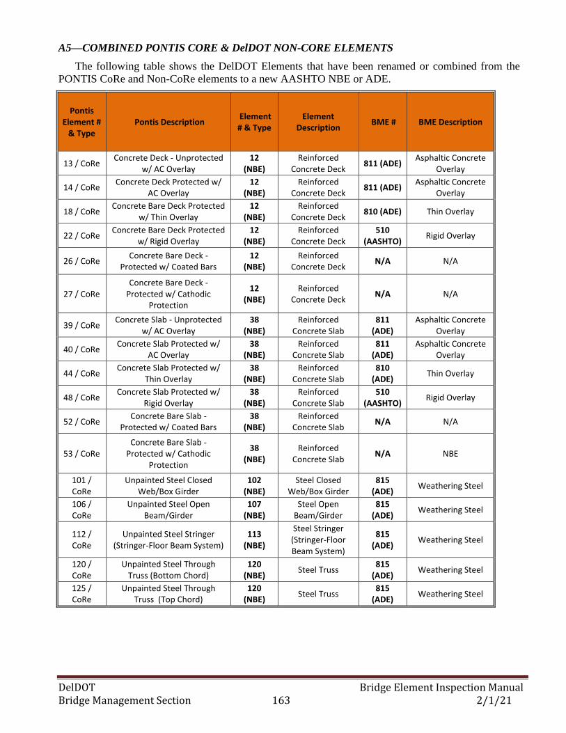
DelDOT Bridge Element Inspection Manual Bridge Management Section 163 2/1/21
A5—COMBINED PONTIS CORE & DelDOT NON-CORE ELEMENTS
The following table shows the DelDOT Elements that have been renamed or combined from the
PONTIS CoRe and Non-CoRe elements to a new AASHTO NBE or ADE.
Pontis Element #
& Type Pontis Description
Element # & Type
Element Description
BME # BME Description
13 / CoRe Concrete Deck - Unprotected
w/ AC Overlay 12
(NBE) Reinforced
Concrete Deck 811 (ADE)
Asphaltic Concrete Overlay
14 / CoRe Concrete Deck Protected w/
AC Overlay 12
(NBE) Reinforced
Concrete Deck 811 (ADE)
Asphaltic Concrete Overlay
18 / CoRe Concrete Bare Deck Protected
w/ Thin Overlay 12
(NBE) Reinforced
Concrete Deck 810 (ADE) Thin Overlay
22 / CoRe Concrete Bare Deck Protected
w/ Rigid Overlay 12
(NBE) Reinforced
Concrete Deck 510
(AASHTO) Rigid Overlay
26 / CoRe Concrete Bare Deck -
Protected w/ Coated Bars 12
(NBE) Reinforced
Concrete Deck N/A N/A
27 / CoRe Concrete Bare Deck -
Protected w/ Cathodic Protection
12 (NBE)
Reinforced Concrete Deck
N/A N/A
39 / CoRe Concrete Slab - Unprotected
w/ AC Overlay 38
(NBE) Reinforced
Concrete Slab 811
(ADE) Asphaltic Concrete
Overlay
40 / CoRe Concrete Slab Protected w/
AC Overlay 38
(NBE) Reinforced
Concrete Slab 811
(ADE) Asphaltic Concrete
Overlay
44 / CoRe Concrete Slab Protected w/
Thin Overlay 38
(NBE) Reinforced
Concrete Slab 810
(ADE) Thin Overlay
48 / CoRe Concrete Slab Protected w/
Rigid Overlay 38
(NBE) Reinforced
Concrete Slab 510
(AASHTO) Rigid Overlay
52 / CoRe Concrete Bare Slab -
Protected w/ Coated Bars 38
(NBE) Reinforced
Concrete Slab N/A N/A
53 / CoRe Concrete Bare Slab -
Protected w/ Cathodic Protection
38 (NBE)
Reinforced Concrete Slab
N/A NBE
101 / CoRe
Unpainted Steel Closed Web/Box Girder
102 (NBE)
Steel Closed Web/Box Girder
815 (ADE)
Weathering Steel
106 / CoRe
Unpainted Steel Open Beam/Girder
107 (NBE)
Steel Open Beam/Girder
815 (ADE)
Weathering Steel
112 / CoRe
Unpainted Steel Stringer (Stringer-Floor Beam System)
113 (NBE)
Steel Stringer (Stringer-Floor Beam System)
815 (ADE)
Weathering Steel
120 / CoRe
Unpainted Steel Through Truss (Bottom Chord)
120 (NBE)
Steel Truss 815
(ADE) Weathering Steel
125 / CoRe
Unpainted Steel Through Truss (Top Chord)
120 (NBE)
Steel Truss 815
(ADE) Weathering Steel
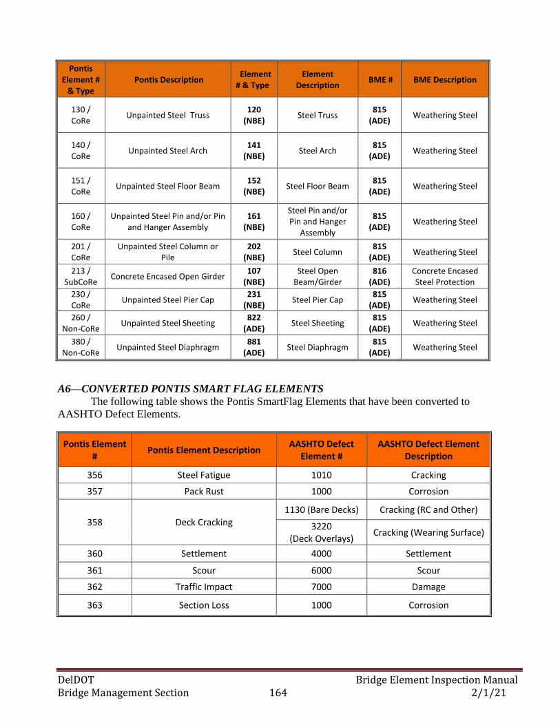
DelDOT Bridge Element Inspection Manual Bridge Management Section 164 2/1/21
Pontis Element #
& Type Pontis Description
Element # & Type
Element Description
BME # BME Description
130 / CoRe
Unpainted Steel Truss 120
(NBE) Steel Truss
815 (ADE)
Weathering Steel
140 / CoRe
Unpainted Steel Arch 141
(NBE) Steel Arch
815 (ADE)
Weathering Steel
151 / CoRe
Unpainted Steel Floor Beam 152
(NBE) Steel Floor Beam
815 (ADE)
Weathering Steel
160 / CoRe
Unpainted Steel Pin and/or Pin and Hanger Assembly
161 (NBE)
Steel Pin and/or Pin and Hanger
Assembly
815 (ADE)
Weathering Steel
201 / CoRe
Unpainted Steel Column or Pile
202 (NBE)
Steel Column 815
(ADE) Weathering Steel
213 / SubCoRe
Concrete Encased Open Girder 107
(NBE) Steel Open
Beam/Girder 816
(ADE) Concrete Encased Steel Protection
230 / CoRe
Unpainted Steel Pier Cap 231
(NBE) Steel Pier Cap
815 (ADE)
Weathering Steel
260 / Non-CoRe
Unpainted Steel Sheeting 822
(ADE) Steel Sheeting
815 (ADE)
Weathering Steel
380 / Non-CoRe
Unpainted Steel Diaphragm 881
(ADE) Steel Diaphragm
815 (ADE)
Weathering Steel
A6—CONVERTED PONTIS SMART FLAG ELEMENTS
The following table shows the Pontis SmartFlag Elements that have been converted to
AASHTO Defect Elements.
Pontis Element #
Pontis Element Description AASHTO Defect
Element # AASHTO Defect Element
Description
356 Steel Fatigue 1010 Cracking
357 Pack Rust 1000 Corrosion
358 Deck Cracking 1130 (Bare Decks) Cracking (RC and Other)
3220 (Deck Overlays)
Cracking (Wearing Surface)
360 Settlement 4000 Settlement
361 Scour 6000 Scour
362 Traffic Impact 7000 Damage
363 Section Loss 1000 Corrosion
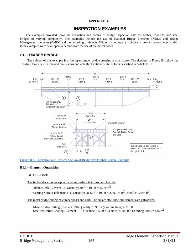
DelDOT Bridge Element Inspection Manual Bridge Management Section 165 2/1/21
2 2 2 2
2
APPENDIX B:
INSPECTION EXAMPLES
The examples provided show the evaluation and coding of bridge inspection data for timber, concrete, and steel
bridges of varying complexity. The examples include the use of National Bridge Elements (NBEs) and Bridge
Management Elements (BMEs) and the recording of defects. While it is an agency’s choice of how to record defect codes,
these examples were developed to demonstrate the use of the defect codes.
B1—TIMBER BRIDGE
The subject of this example is a four-span timber bridge crossing a small creek. The sketches in Figure B-1 show the
bridge elements with relevant dimensions and note the locations of the defects described in Article B1.2.
0′ 61/ ″
c.l. Abut. 1
26′ 111/ ″
Span 1
Bent 2
27′ 0″
Span 2
109′ 0″
Bent 3
27′ 0″
Span 3
Bent 4
26′ 111/ ″
Span 4
0′ 61/ ″
c.l. Abut. 5
4
1 2
Timber Lagging, 3 Full Width of Abutment Cap Beam
30′ × 51/ ″
Timber Deck
11 EA 8″ × 22″
Timber Girders
12″ × 12″ × 34′ 0″
Timber Cap at
Piers and Abutments
30′ 0″
Out-to-Out
28′ 5″
Curb-to-Curb
2
3″ Asphalt Overlay
6″ Square Steel Tube
Rail with Timber Posts
and Curb
12 dia. Timber Piles
3
5′ 9″
Typ.
Circled numbers correspond to
defects described in Articles B1.2.1
through B1.2.4
Figure B-1—Elevation and Typical Section of Bridge for Timber Bridge Example
B1.1—Element Quantities
B1.1.1—Deck
The timber deck has an asphalt wearing surface that runs curb to curb:
Timber Deck (Element 31) Quantity: 30 ft × 109 ft = 3,270 ft2
Wearing Surface (Element 811) Quantity: 28.42 ft × 109 ft = 3,097.78 ft2 (round to 3,098 ft2)
The metal bridge railing has timber posts and curb. The square steel tube rail elements are galvanized:
Metal Bridge Railing (Element 330) Quantity: 109 ft × (2 railing lines) = 218 ft
Steel Protective Coating (Element 515) Quantity: 0.50 ft × (4 sides) × 109 ft × (2 railing lines) = 436 ft2
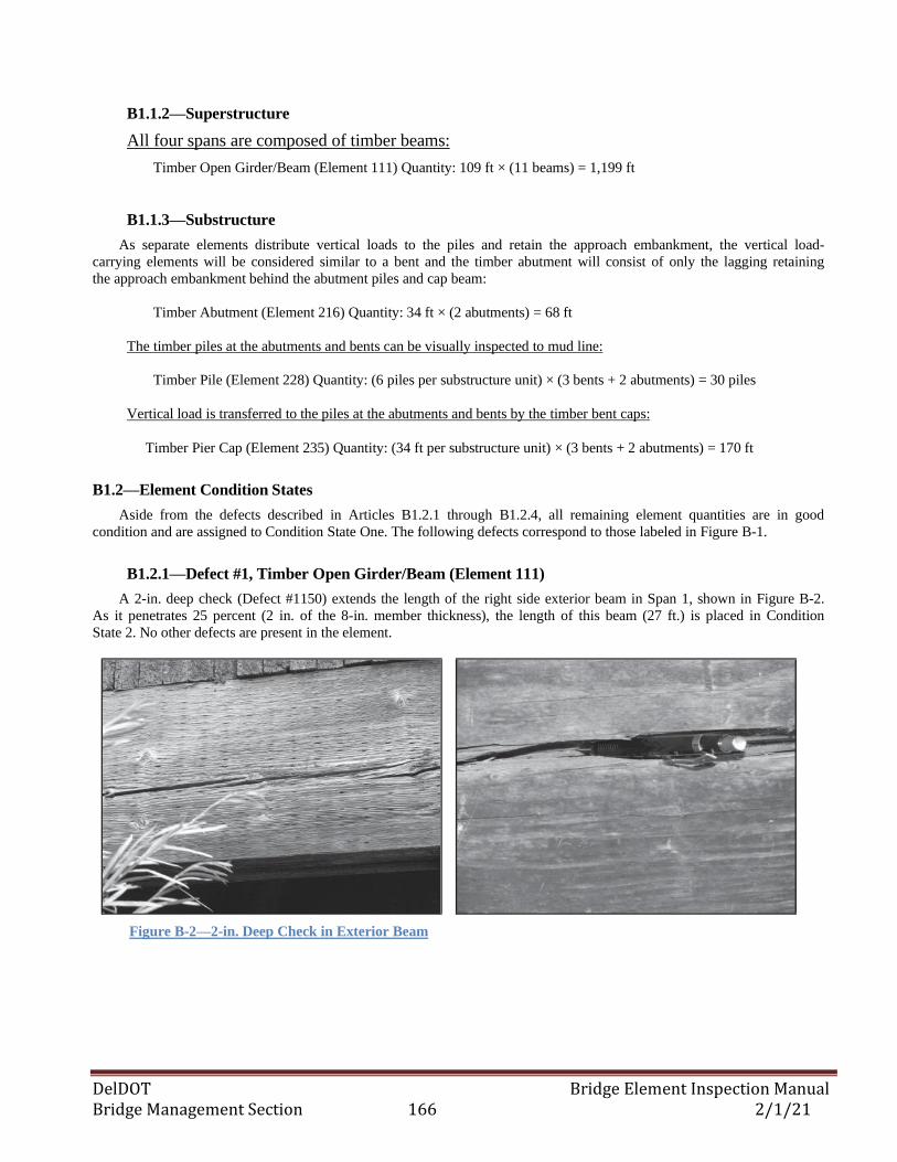
DelDOT Bridge Element Inspection Manual Bridge Management Section 166 2/1/21
B1.1.2—Superstructure
All four spans are composed of timber beams:
Timber Open Girder/Beam (Element 111) Quantity: 109 ft × (11 beams) = 1,199 ft
B1.1.3—Substructure
As separate elements distribute vertical loads to the piles and retain the approach embankment, the vertical load-
carrying elements will be considered similar to a bent and the timber abutment will consist of only the lagging retaining
the approach embankment behind the abutment piles and cap beam:
Timber Abutment (Element 216) Quantity: 34 ft × (2 abutments) = 68 ft
The timber piles at the abutments and bents can be visually inspected to mud line:
Timber Pile (Element 228) Quantity: (6 piles per substructure unit) × (3 bents + 2 abutments) = 30 piles
Vertical load is transferred to the piles at the abutments and bents by the timber bent caps:
Timber Pier Cap (Element 235) Quantity: (34 ft per substructure unit) × (3 bents + 2 abutments) = 170 ft
B1.2—Element Condition States
Aside from the defects described in Articles B1.2.1 through B1.2.4, all remaining element quantities are in good
condition and are assigned to Condition State One. The following defects correspond to those labeled in Figure B-1.
B1.2.1—Defect #1, Timber Open Girder/Beam (Element 111)
A 2-in. deep check (Defect #1150) extends the length of the right side exterior beam in Span 1, shown in Figure B-2.
As it penetrates 25 percent (2 in. of the 8-in. member thickness), the length of this beam (27 ft.) is placed in Condition
State 2. No other defects are present in the element.
Figure B-2—2-in. Deep Check in Exterior Beam
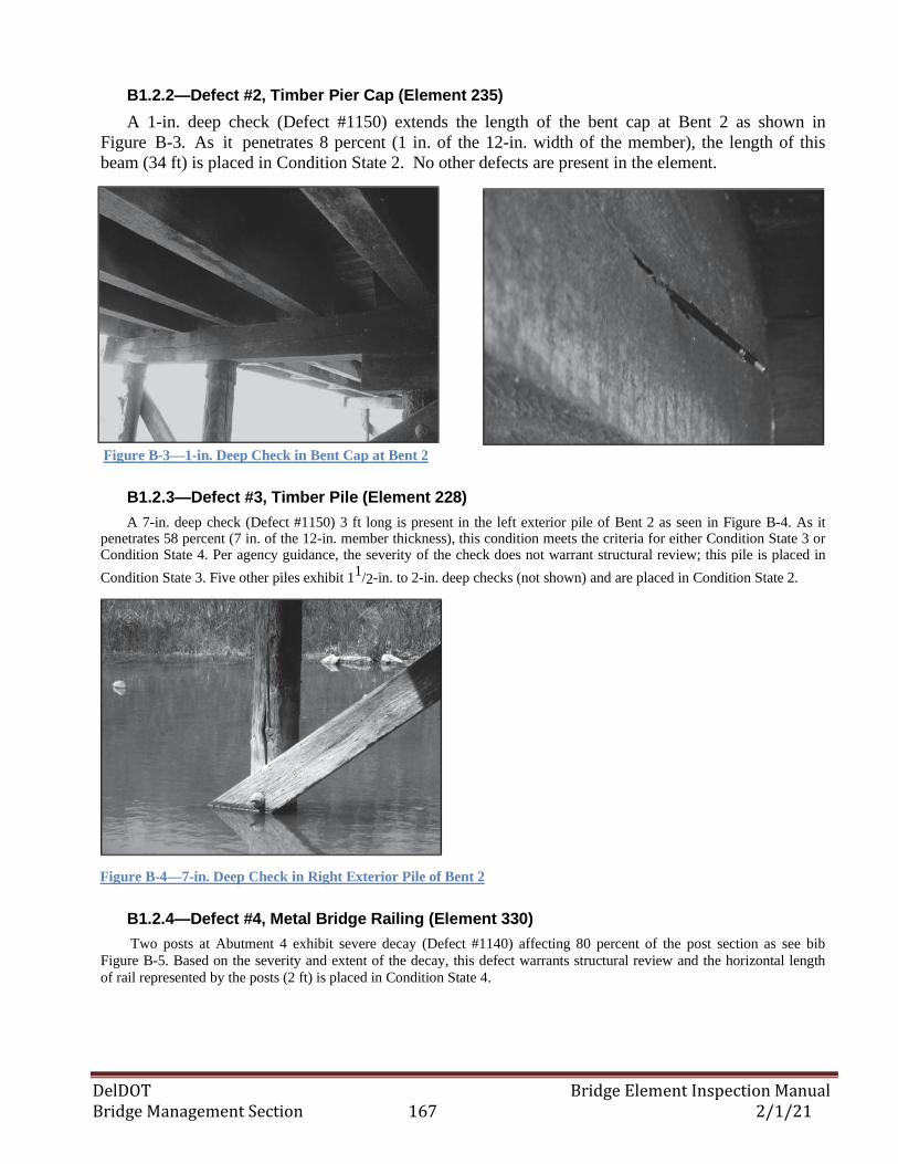
DelDOT Bridge Element Inspection Manual Bridge Management Section 167 2/1/21
B1.2.2—Defect #2, Timber Pier Cap (Element 235)
A 1-in. deep check (Defect #1150) extends the length of the bent cap at Bent 2 as shown in
Figure B-3. As it penetrates 8 percent (1 in. of the 12-in. width of the member), the length of this
beam (34 ft) is placed in Condition State 2. No other defects are present in the element.
Figure B-3—1-in. Deep Check in Bent Cap at Bent 2
B1.2.3—Defect #3, Timber Pile (Element 228)
A 7-in. deep check (Defect #1150) 3 ft long is present in the left exterior pile of Bent 2 as seen in Figure B-4. As it penetrates 58 percent (7 in. of the 12-in. member thickness), this condition meets the criteria for either Condition State 3 or Condition State 4. Per agency guidance, the severity of the check does not warrant structural review; this pile is placed in
Condition State 3. Five other piles exhibit 11/2-in. to 2-in. deep checks (not shown) and are placed in Condition State 2.
Figure B-4—7-in. Deep Check in Right Exterior Pile of Bent 2
B1.2.4—Defect #4, Metal Bridge Railing (Element 330)
Two posts at Abutment 4 exhibit severe decay (Defect #1140) affecting 80 percent of the post section as see bib
Figure B-5. Based on the severity and extent of the decay, this defect warrants structural review and the horizontal length
of rail represented by the posts (2 ft) is placed in Condition State 4.
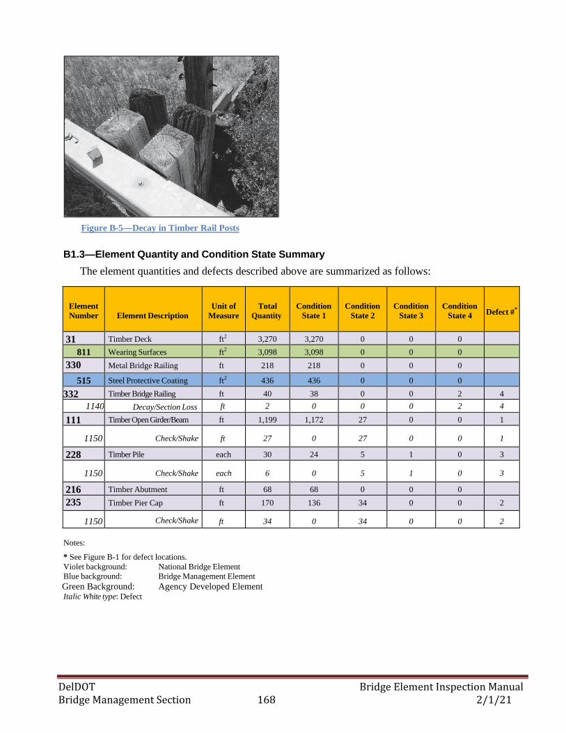
DelDOT Bridge Element Inspection Manual Bridge Management Section 168 2/1/21
Figure B-5—Decay in Timber Rail Posts
B1.3—Element Quantity and Condition State Summary
The element quantities and defects described above are summarized as follows:
Element
Number
Element Description
Unit of
Measure
Total
Quantity
Condition
State 1
Condition
State 2
Condition
State 3
Condition
State 4
Defect #*
31 Timber Deck ft2 3,270 3,270 0 0 0
811 Wearing Surfaces ft2 3,098 3,098 0 0 0
330 Metal Bridge Railing ft 218 218 0 0 0
515 Steel Protective Coating ft2 436 436 0 0 0
332 Timber Bridge Railing ft 40 38 0 0 2 4
1140 Decay/Section Loss ft 2 0 0 0 2 4
111 Timber Open Girder/Beam ft 1,199 1,172 27 0 0 1
1150 Check/Shake ft 27 0 27 0 0 1
228 Timber Pile each 30 24 5 1 0 3
1150 Check/Shake each 6 0 5 1 0 3
216 Timber Abutment ft 68 68 0 0 0
235 Timber Pier Cap ft 170 136 34 0 0 2
1150 Check/Shake ft 34 0 34 0 0 2
Notes:
* See Figure B-1 for defect locations.
Violet background: National Bridge Element
Blue background: Bridge Management Element
Green Background: Agency Developed Element Italic White type: Defect
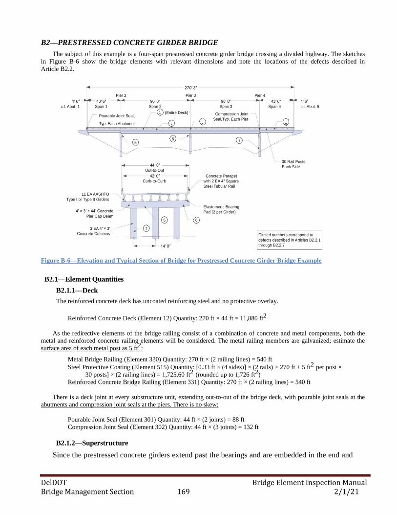
DelDOT Bridge Element Inspection Manual Bridge Management Section 169 2/1/21
B2—PRESTRESSED CONCRETE GIRDER BRIDGE
The subject of this example is a four-span prestressed concrete girder bridge crossing a divided highway. The sketches
in Figure B-6 show the bridge elements with relevant dimensions and note the locations of the defects described in
Article B2.2.
1′ 6″
c.l. Abut. 1
43′ 6″
Span 1
Pier 2
90′ 0″
Span 2
270′ 3″
Pier 3
90′ 0″
Span 3
Pier 4
43′ 6″
Span 4
1′ 6″
c.l. Abut. 5
Pourable Joint Seal, 1 (Entire Deck) Compression Joint
Seal,Typ. Each Pier Typ. Each Abutment
2 4 3
5 6 7
11 EA AASHTO
Type I or Type II Girders
4′ × 3′ × 44′ Concrete
Pier Cap Beam
44′ 0″
Out-to-Out
42′ 0″
Curb-to-Curb
5
Concrete Parapet
with 2 EA 4″ Square
Steel Tubular Rail
Elastomeric Bearing
Pad (2 per Girder)
6
30 Rail Posts,
Each Side
3 EA 4′ × 3′
Concrete Columns
7
14′ 0″
Circled numbers correspond to
defects described in Articles B2.2.1
through B2.2.7
Figure B-6—Elevation and Typical Section of Bridge for Prestressed Concrete Girder Bridge Example
B2.1—Element Quantities
B2.1.1—Deck
The reinforced concrete deck has uncoated reinforcing steel and no protective overlay.
Reinforced Concrete Deck (Element 12) Quantity: 270 ft × 44 ft = 11,880 ft2
As the redirective elements of the bridge railing consist of a combination of concrete and metal components, both the
metal and reinforced concrete railing elements will be considered. The metal railing members are galvanized; estimate the
surface area of each metal post as 5 ft2
:
Metal Bridge Railing (Element 330) Quantity: 270 ft × (2 railing lines) = 540 ft
Steel Protective Coating (Element 515) Quantity: [0.33 ft × (4 sides)] × (2 rails) × 270 ft + 5 ft2 per post ×
30 posts] × (2 railing lines) = 1,725.60 ft2 (rounded up to 1,726 ft2)
Reinforced Concrete Bridge Railing (Element 331) Quantity: 270 ft × (2 railing lines) = 540 ft
There is a deck joint at every substructure unit, extending out-to-out of the bridge deck, with pourable joint seals at the
abutments and compression joint seals at the piers. There is no skew:
Pourable Joint Seal (Element 301) Quantity: 44 ft × (2 joints) = 88 ft
Compression Joint Seal (Element 302) Quantity: 44 ft × (3 joints) = 132 ft
B2.1.2—Superstructure
Since the prestressed concrete girders extend past the bearings and are embedded in the end and
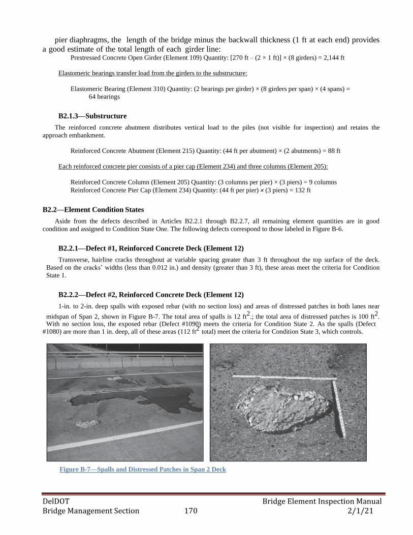
DelDOT Bridge Element Inspection Manual Bridge Management Section 170 2/1/21
pier diaphragms, the length of the bridge minus the backwall thickness (1 ft at each end) provides
a good estimate of the total length of each girder line: Prestressed Concrete Open Girder (Element 109) Quantity: [270 ft – (2 × 1 ft)] × (8 girders) = 2,144 ft
Elastomeric bearings transfer load from the girders to the substructure:
Elastomeric Bearing (Element 310) Quantity: (2 bearings per girder) × (8 girders per span) × (4 spans) =
64 bearings
B2.1.3—Substructure
The reinforced concrete abutment distributes vertical load to the piles (not visible for inspection) and retains the
approach embankment.
Reinforced Concrete Abutment (Element 215) Quantity: (44 ft per abutment) × (2 abutments) = 88 ft
Each reinforced concrete pier consists of a pier cap (Element 234) and three columns (Element 205):
Reinforced Concrete Column (Element 205) Quantity: (3 columns per pier) × (3 piers) = 9 columns
Reinforced Concrete Pier Cap (Element 234) Quantity: (44 ft per pier) × (3 piers) = 132 ft
B2.2—Element Condition States
Aside from the defects described in Articles B2.2.1 through B2.2.7, all remaining element quantities are in good
condition and assigned to Condition State One. The following defects correspond to those labeled in Figure B-6.
B2.2.1—Defect #1, Reinforced Concrete Deck (Element 12)
Transverse, hairline cracks throughout at variable spacing greater than 3 ft throughout the top surface of the deck.
Based on the cracks’ widths (less than 0.012 in.) and density (greater than 3 ft), these areas meet the criteria for Condition
State 1.
B2.2.2—Defect #2, Reinforced Concrete Deck (Element 12)
1-in. to 2-in. deep spalls with exposed rebar (with no section loss) and areas of distressed patches in both lanes near
midspan of Span 2, shown in Figure B-7. The total area of spalls is 12 ft2
.; the total area of distressed patches is 100 ft2.
With no section loss, the exposed rebar (Defect #1090) meets the criteria for Condition State 2. As the spalls (Defect
#1080) are more than 1 in. deep, all of these areas (112 ft2
total) meet the criteria for Condition State 3, which controls.
Figure B-7—Spalls and Distressed Patches in Span 2 Deck
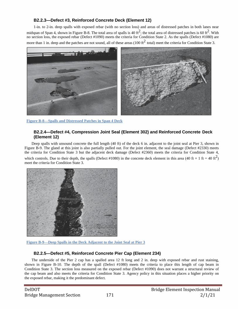
DelDOT Bridge Element Inspection Manual Bridge Management Section 171 2/1/21
B2.2.3—Defect #3, Reinforced Concrete Deck (Element 12)
1-in. to 2-in. deep spalls with exposed rebar (with no section loss) and areas of distressed patches in both lanes near
midspan of Span 4, shown in Figure B-8. The total area of spalls is 40 ft2
; the total area of distressed patches is 60 ft2. With
no section loss, the exposed rebar (Defect #1090) meets the criteria for Condition State 2. As the spalls (Defect #1080) are
more than 1 in. deep and the patches are not sound, all of these areas (100 ft2
total) meet the criteria for Condition State 3.
Figure B-8—Spalls and Distressed Patches in Span 4 Deck
B2.2.4—Defect #4, Compression Joint Seal (Element 302) and Reinforced Concrete Deck (Element 12)
Deep spalls with unsound concrete the full length (40 ft) of the deck 6 in. adjacent to the joint seal at Pier 3, shown in Figure B-9. The gland at this joint is also partially pulled out. For the joint element, the seal damage (Defect #2330) meets the criteria for Condition State 3 but the adjacent deck damage (Defect #2360) meets the criteria for Condition State 4,
which controls. Due to their depth, the spalls (Defect #1080) in the concrete deck element in this area (40 ft × 1 ft = 40 ft2)
meet the criteria for Condition State 3.
Figure B-9—Deep Spalls in the Deck Adjacent to the Joint Seal at Pier 3
B2.2.5—Defect #5, Reinforced Concrete Pier Cap (Element 234)
The underside of the Pier 2 cap has a spalled area 12 ft long and 2 in. deep with exposed rebar and rust staining,
shown in Figure B-10. The depth of the spall (Defect #1080) meets the criteria to place this length of cap beam in
Condition State 3. The section loss measured on the exposed rebar (Defect #1090) does not warrant a structural review of
the cap beam and also meets the criteria for Condition State 3. Agency policy in this situation places a higher priority on
the exposed rebar, making it the predominant defect.
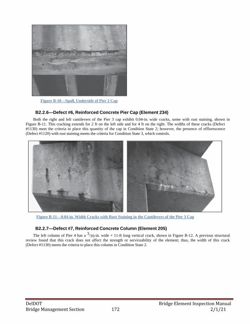
DelDOT Bridge Element Inspection Manual Bridge Management Section 172 2/1/21
Figure B-10—Spall, Underside of Pier 2 Cap
B2.2.6—Defect #6, Reinforced Concrete Pier Cap (Element 234)
Both the right and left cantilevers of the Pier 3 cap exhibit 0.04-in. wide cracks, some with rust staining, shown in
Figure B-11. This cracking extends for 2 ft on the left side and for 4 ft on the right. The widths of these cracks (Defect
#1130) meet the criteria to place this quantity of the cap in Condition State 2; however, the presence of efflorescence
(Defect #1120) with rust staining meets the criteria for Condition State 3, which controls.
Figure B-11—0.04-in. Width Cracks with Rust Staining in the Cantilevers of the Pier 3 Cap
B2.2.7—Defect #7, Reinforced Concrete Column (Element 205)
The left column of Pier 4 has a 3
/16-in. wide × 11-ft long vertical crack, shown in Figure B-12. A previous structural
review found that this crack does not affect the strength or serviceability of the element; thus, the width of this crack
(Defect #1130) meets the criteria to place this column in Condition State 2.
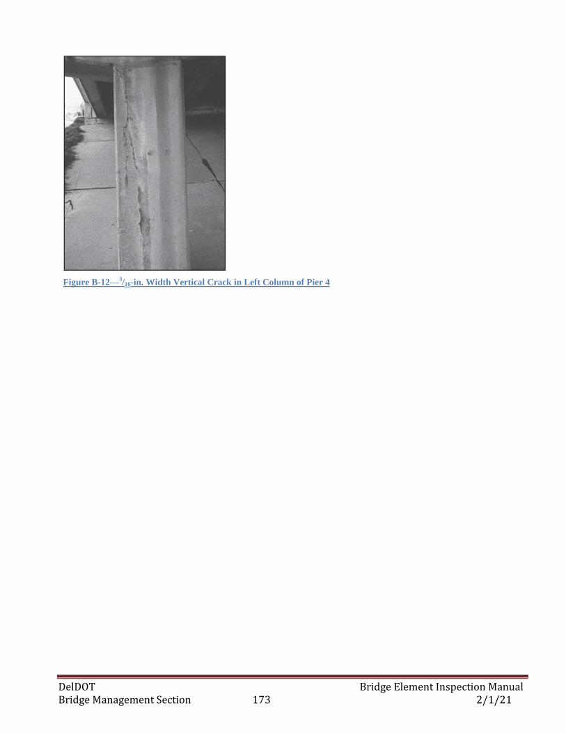
DelDOT Bridge Element Inspection Manual Bridge Management Section 173 2/1/21
Figure B-12—3/16-in. Width Vertical Crack in Left Column of Pier 4
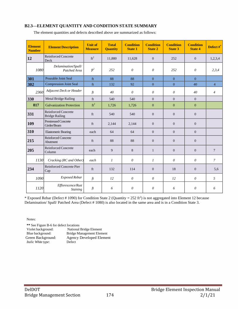
DelDOT Bridge Element Inspection Manual Bridge Management Section 174 2/1/21
B2.3—ELEMENT QUANTITY AND CONDITION STATE SUMMARY
The element quantities and defects described above are summarized as follows:
Element
Number
Element Description
Unit of
Measure
Total
Quantity
Condition
State 1
Condition
State 2
Condition
State 3
Condition
State 4 Defect #*
12 Reinforced Concrete
Deck ft2
11,880 11,628 0 252 0 1,2,3,4
1080 Delamination/Spall/
Patched Area ft2 252 0 0 252 0 2,3,4
301 Pourable Joint Seal ft 88 88 0 0 0
302 Compression Joint Seal ft 132 92 0 0 40 4
2360 Adjacent Deck or Header
ft 40 0 0 0 40 4
330 Metal Bridge Railing ft 540 540 0 0 0
817 Galvanization Protection ft2 1,726 1,726 0 0 0
331 Reinforced Concrete
Bridge Railing ft 540 540 0 0 0
109 Prestressed Concrete
Girder/Beam ft 2,144 2,144 0 0 0
310 Elastomeric Bearing each 64 64 0 0 0
215 Reinforced Concrete
Abutment ft 88 88 0 0 0
205 Reinforced Concrete
Column each 9 8 1 0 0 7
1130 Cracking (RC and Other) each 1 0 1 0 0 7
234 Reinforced Concrete Pier
Cap ft 132 114 0 18 0 5,6
1090 Exposed Rebar ft 12 0 0 12 0 5
1120 Efflorescence/Rust
Staining ft 6 0 0 6 0 6
* Exposed Rebar (Defect # 1090) for Condition State 2 (Quantity = 252 ft2) is not aggregated into Element 12 because
Delamination/ Spall/ Patched Area (Defect # 1080) is also located in the same area and is in a Condition State 3.
Notes:
** See Figure B-6 for defect locations
Violet background: National Bridge Element
Blue background: Bridge Management Element
Green Background: Agency Developed Element Italic White type: Defect
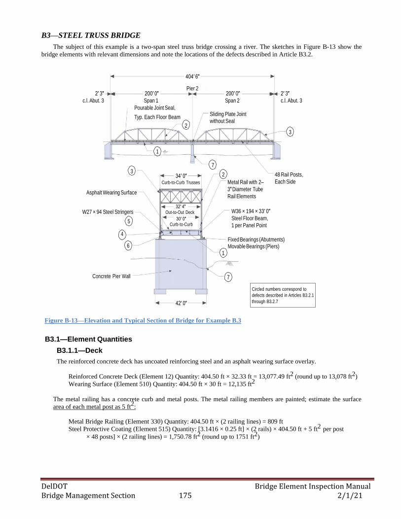
DelDOT Bridge Element Inspection Manual Bridge Management Section 175 2/1/21
B3—STEEL TRUSS BRIDGE
The subject of this example is a two-span steel truss bridge crossing a river. The sketches in Figure B-13 show the
bridge elements with relevant dimensions and note the locations of the defects described in Article B3.2.
404′ 6″
2′ 3″
c.l. Abut. 3
200′ 0″
Span 1
Pourable Joint Seal,
Pier 2
200′ 0″
Span 2
2′ 3″
c.l. Abut. 3
Typ. Each Floor Beam Sliding Plate Joint
without Seal 2
3
1
3
Asphalt Wearing Surface
W27 × 94 Steel Stringers
5
4
34′ 0″
Curb-to-Curb Trusses
32′ 4″ Out-to-Out Deck
30′ 0″ Curb-to-Curb
7
2
Metal Rail with 2–
3″ Diameter Tube
Rail Elements
W36 × 194 × 33′ 0″
Steel Floor Beam,
1 per Panel Point
48 Rail Posts,
Each Side
Fixed Bearings (Abutments) 6 Movable Bearings (Piers)
1
Concrete Pier Wall 7
42′ 0″
Circled numbers correspond to
defects described in Articles B3.2.1
through B3.2.7
Figure B-13—Elevation and Typical Section of Bridge for Example B.3
B3.1—Element Quantities
B3.1.1—Deck
The reinforced concrete deck has uncoated reinforcing steel and an asphalt wearing surface overlay.
Reinforced Concrete Deck (Element 12) Quantity: 404.50 ft × 32.33 ft = 13,077.49 ft2 (round up to 13,078 ft2)
Wearing Surface (Element 510) Quantity: 404.50 ft × 30 ft = 12,135 ft2
The metal railing has a concrete curb and metal posts. The metal railing members are painted; estimate the surface
area of each metal post as 5 ft2
:
Metal Bridge Railing (Element 330) Quantity: 404.50 ft × (2 railing lines) = 809 ft
Steel Protective Coating (Element 515) Quantity: [3.1416 × 0.25 ft] × (2 rails) × 404.50 ft + 5 ft2 per post
× 48 posts] × (2 railing lines) = 1,750.78 ft2 (round up to 1751 ft2)
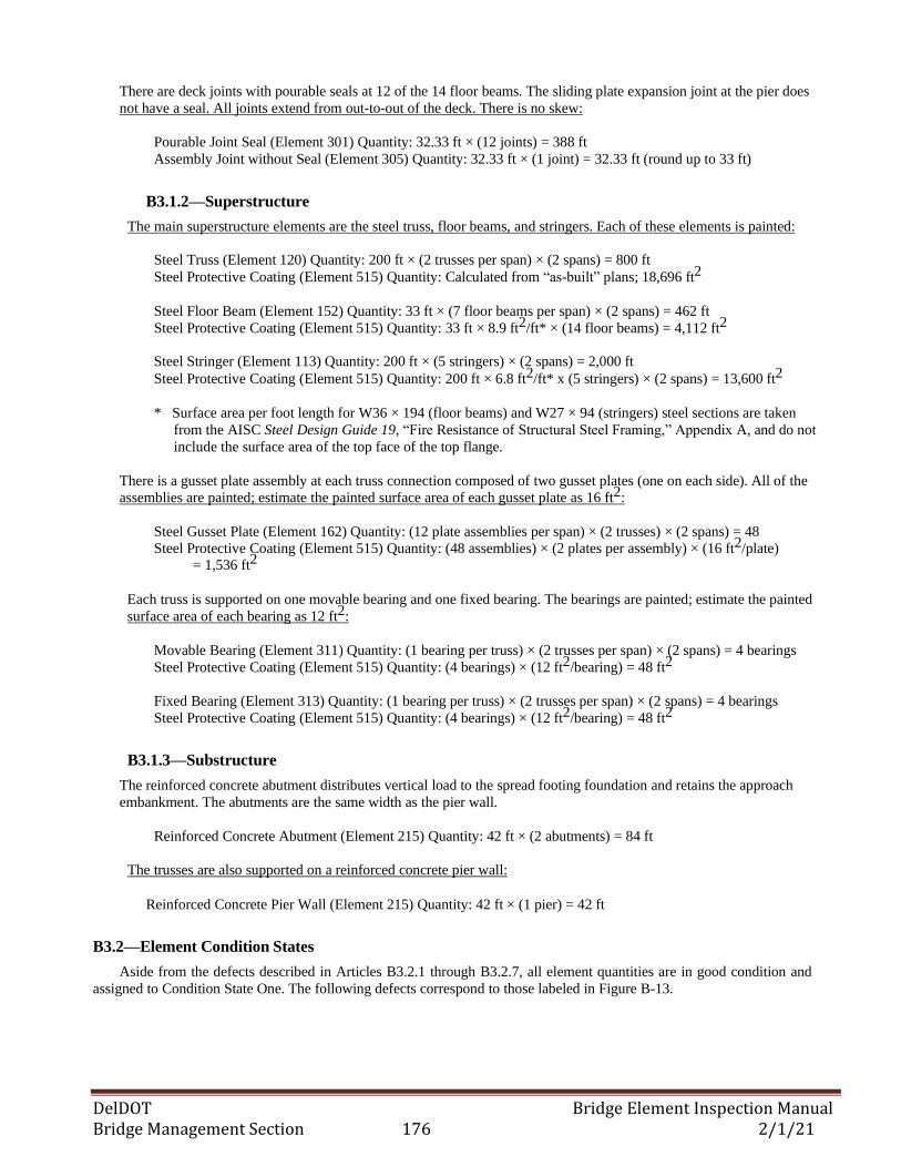
DelDOT Bridge Element Inspection Manual Bridge Management Section 176 2/1/21
There are deck joints with pourable seals at 12 of the 14 floor beams. The sliding plate expansion joint at the pier does
not have a seal. All joints extend from out-to-out of the deck. There is no skew:
Pourable Joint Seal (Element 301) Quantity: 32.33 ft × (12 joints) = 388 ft
Assembly Joint without Seal (Element 305) Quantity: 32.33 ft × (1 joint) = 32.33 ft (round up to 33 ft)
B3.1.2—Superstructure
The main superstructure elements are the steel truss, floor beams, and stringers. Each of these elements is painted:
Steel Truss (Element 120) Quantity: 200 ft × (2 trusses per span) × (2 spans) = 800 ft
Steel Protective Coating (Element 515) Quantity: Calculated from “as-built” plans; 18,696 ft2
Steel Floor Beam (Element 152) Quantity: 33 ft × (7 floor beams per span) × (2 spans) = 462 ft
Steel Protective Coating (Element 515) Quantity: 33 ft × 8.9 ft2/ft* × (14 floor beams) = 4,112 ft2
Steel Stringer (Element 113) Quantity: 200 ft × (5 stringers) × (2 spans) = 2,000 ft
Steel Protective Coating (Element 515) Quantity: 200 ft × 6.8 ft2/ft* x (5 stringers) × (2 spans) = 13,600 ft2
* Surface area per foot length for W36 × 194 (floor beams) and W27 × 94 (stringers) steel sections are taken
from the AISC Steel Design Guide 19, “Fire Resistance of Structural Steel Framing,” Appendix A, and do not
include the surface area of the top face of the top flange.
There is a gusset plate assembly at each truss connection composed of two gusset plates (one on each side). All of the
assemblies are painted; estimate the painted surface area of each gusset plate as 16 ft2:
Steel Gusset Plate (Element 162) Quantity: (12 plate assemblies per span) × (2 trusses) × (2 spans) = 48
Steel Protective Coating (Element 515) Quantity: (48 assemblies) × (2 plates per assembly) × (16 ft2/plate) = 1,536 ft2
Each truss is supported on one movable bearing and one fixed bearing. The bearings are painted; estimate the painted
surface area of each bearing as 12 ft2:
Movable Bearing (Element 311) Quantity: (1 bearing per truss) × (2 trusses per span) × (2 spans) = 4 bearings
Steel Protective Coating (Element 515) Quantity: (4 bearings) × (12 ft2/bearing) = 48 ft2
Fixed Bearing (Element 313) Quantity: (1 bearing per truss) × (2 trusses per span) × (2 spans) = 4 bearings
Steel Protective Coating (Element 515) Quantity: (4 bearings) × (12 ft2/bearing) = 48 ft2
B3.1.3—Substructure
The reinforced concrete abutment distributes vertical load to the spread footing foundation and retains the approach
embankment. The abutments are the same width as the pier wall.
Reinforced Concrete Abutment (Element 215) Quantity: 42 ft × (2 abutments) = 84 ft
The trusses are also supported on a reinforced concrete pier wall:
Reinforced Concrete Pier Wall (Element 215) Quantity: 42 ft × (1 pier) = 42 ft
B3.2—Element Condition States
Aside from the defects described in Articles B3.2.1 through B3.2.7, all element quantities are in good condition and
assigned to Condition State One. The following defects correspond to those labeled in Figure B-13.
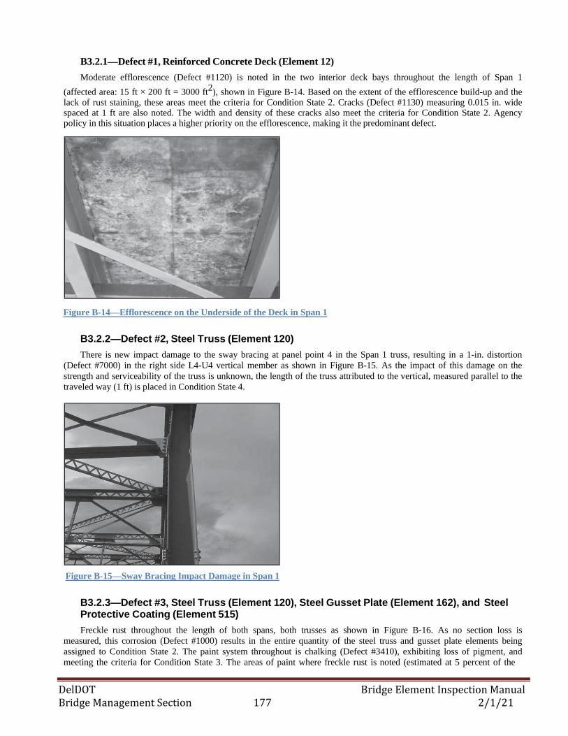
DelDOT Bridge Element Inspection Manual Bridge Management Section 177 2/1/21
B3.2.1—Defect #1, Reinforced Concrete Deck (Element 12)
Moderate efflorescence (Defect #1120) is noted in the two interior deck bays throughout the length of Span 1
(affected area: 15 ft × 200 ft = 3000 ft2), shown in Figure B-14. Based on the extent of the efflorescence build-up and the
lack of rust staining, these areas meet the criteria for Condition State 2. Cracks (Defect #1130) measuring 0.015 in. wide spaced at 1 ft are also noted. The width and density of these cracks also meet the criteria for Condition State 2. Agency policy in this situation places a higher priority on the efflorescence, making it the predominant defect.
Figure B-14—Efflorescence on the Underside of the Deck in Span 1
B3.2.2—Defect #2, Steel Truss (Element 120)
There is new impact damage to the sway bracing at panel point 4 in the Span 1 truss, resulting in a 1-in. distortion
(Defect #7000) in the right side L4-U4 vertical member as shown in Figure B-15. As the impact of this damage on the
strength and serviceability of the truss is unknown, the length of the truss attributed to the vertical, measured parallel to the
traveled way (1 ft) is placed in Condition State 4.
Figure B-15—Sway Bracing Impact Damage in Span 1
B3.2.3—Defect #3, Steel Truss (Element 120), Steel Gusset Plate (Element 162), and Steel Protective Coating (Element 515)
Freckle rust throughout the length of both spans, both trusses as shown in Figure B-16. As no section loss is
measured, this corrosion (Defect #1000) results in the entire quantity of the steel truss and gusset plate elements being
assigned to Condition State 2. The paint system throughout is chalking (Defect #3410), exhibiting loss of pigment, and
meeting the criteria for Condition State 3. The areas of paint where freckle rust is noted (estimated at 5 percent of the
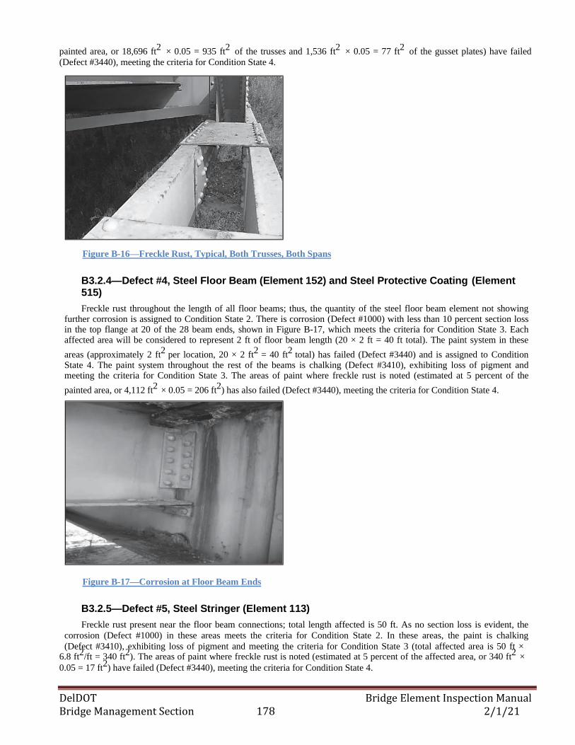
DelDOT Bridge Element Inspection Manual Bridge Management Section 178 2/1/21
painted area, or 18,696 ft2
× 0.05 = 935 ft2
of the trusses and 1,536 ft2
× 0.05 = 77 ft2
of the gusset plates) have failed
(Defect #3440), meeting the criteria for Condition State 4.
Figure B-16—Freckle Rust, Typical, Both Trusses, Both Spans
B3.2.4—Defect #4, Steel Floor Beam (Element 152) and Steel Protective Coating (Element 515)
Freckle rust throughout the length of all floor beams; thus, the quantity of the steel floor beam element not showing further corrosion is assigned to Condition State 2. There is corrosion (Defect #1000) with less than 10 percent section loss in the top flange at 20 of the 28 beam ends, shown in Figure B-17, which meets the criteria for Condition State 3. Each affected area will be considered to represent 2 ft of floor beam length (20 × 2 ft = 40 ft total). The paint system in these
areas (approximately 2 ft2
per location, 20 × 2 ft2
= 40 ft2
total) has failed (Defect #3440) and is assigned to Condition State 4. The paint system throughout the rest of the beams is chalking (Defect #3410), exhibiting loss of pigment and meeting the criteria for Condition State 3. The areas of paint where freckle rust is noted (estimated at 5 percent of the
painted area, or 4,112 ft2
× 0.05 = 206 ft2
) has also failed (Defect #3440), meeting the criteria for Condition State 4.
Figure B-17—Corrosion at Floor Beam Ends
B3.2.5—Defect #5, Steel Stringer (Element 113)
Freckle rust present near the floor beam connections; total length affected is 50 ft. As no section loss is evident, the
corrosion (Defect #1000) in these areas meets the criteria for Condition State 2. In these areas, the paint is chalking
(Defect #3410), exhibiting loss of pigment and meeting the criteria for Condition State 3 (total affected area is 50 ft × 6.8 ft
2/ft = 340 ft
2). The areas of paint where freckle rust is noted (estimated at 5 percent of the affected area, or 340 ft
2 ×
0.05 = 17 ft2) have failed (Defect #3440), meeting the criteria for Condition State 4.
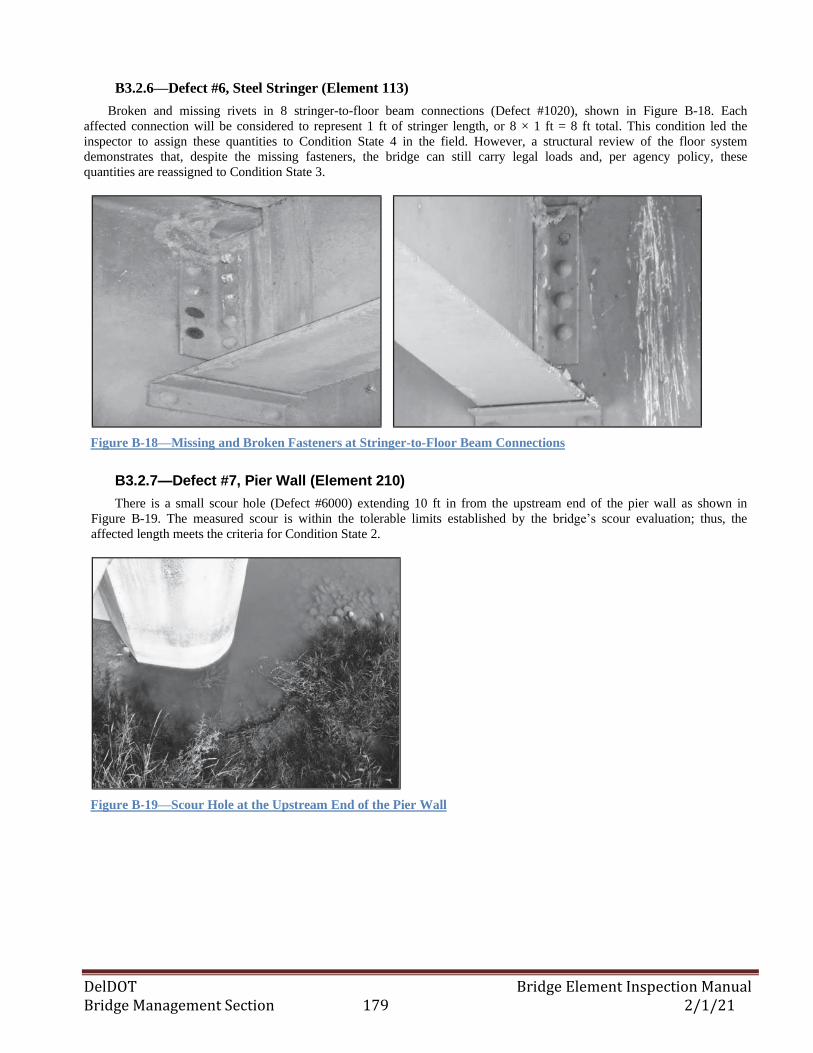
DelDOT Bridge Element Inspection Manual Bridge Management Section 179 2/1/21
B3.2.6—Defect #6, Steel Stringer (Element 113)
Broken and missing rivets in 8 stringer-to-floor beam connections (Defect #1020), shown in Figure B-18. Each
affected connection will be considered to represent 1 ft of stringer length, or 8 × 1 ft = 8 ft total. This condition led the
inspector to assign these quantities to Condition State 4 in the field. However, a structural review of the floor system
demonstrates that, despite the missing fasteners, the bridge can still carry legal loads and, per agency policy, these
quantities are reassigned to Condition State 3.
Figure B-18—Missing and Broken Fasteners at Stringer-to-Floor Beam Connections
B3.2.7—Defect #7, Pier Wall (Element 210)
There is a small scour hole (Defect #6000) extending 10 ft in from the upstream end of the pier wall as shown in
Figure B-19. The measured scour is within the tolerable limits established by the bridge’s scour evaluation; thus, the
affected length meets the criteria for Condition State 2.
Figure B-19—Scour Hole at the Upstream End of the Pier Wall
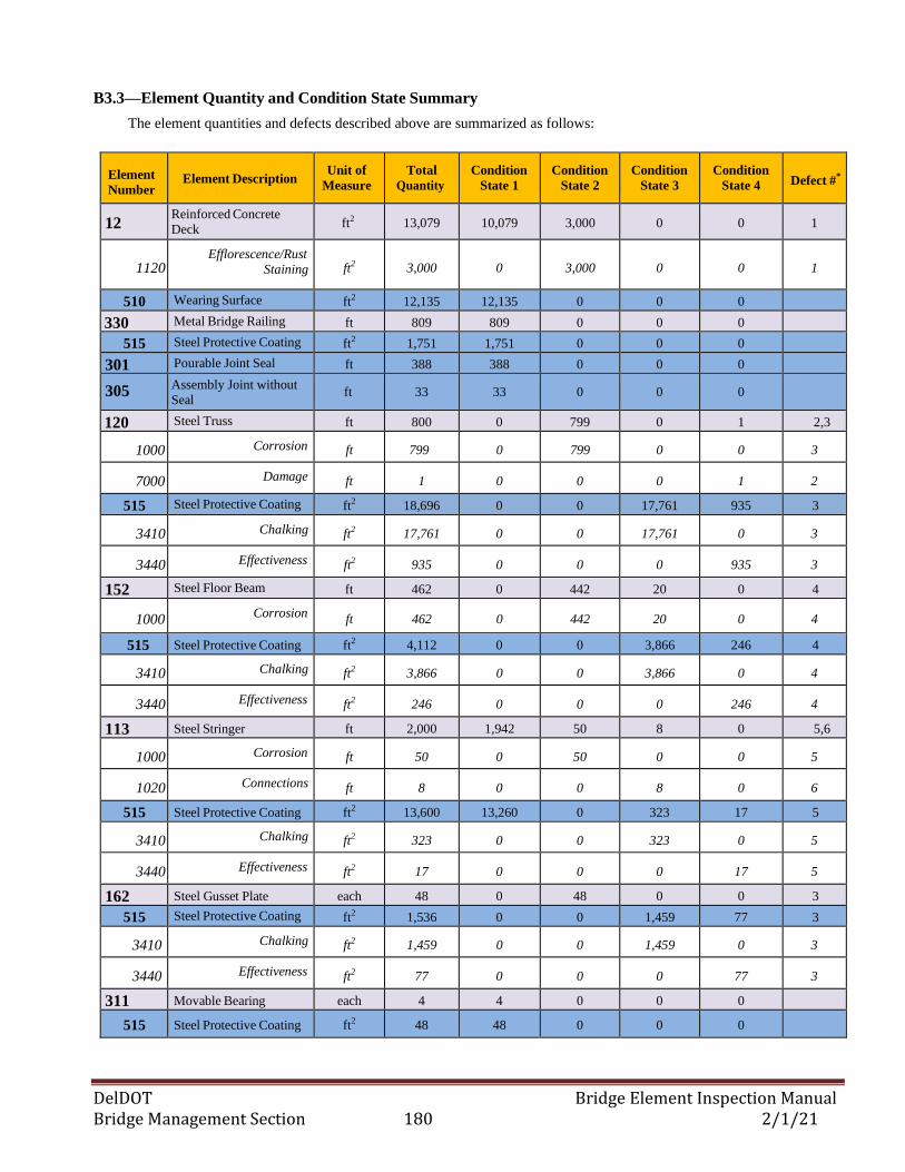
DelDOT Bridge Element Inspection Manual Bridge Management Section 180 2/1/21
B3.3—Element Quantity and Condition State Summary
The element quantities and defects described above are summarized as follows:
Element
Number
Element Description
Unit of
Measure
Total
Quantity
Condition
State 1
Condition
State 2
Condition
State 3
Condition
State 4
Defect #*
12 Reinforced Concrete
Deck ft2
13,079 10,079 3,000 0 0 1
1120 Efflorescence/Rust
Staining ft2 3,000 0 3,000 0 0 1
510 Wearing Surface ft2 12,135 12,135 0 0 0
330 Metal Bridge Railing ft 809 809 0 0 0
515 Steel Protective Coating ft2 1,751 1,751 0 0 0
301 Pourable Joint Seal ft 388 388 0 0 0
305 Assembly Joint without
Seal ft 33 33 0 0 0
120 Steel Truss ft 800 0 799 0 1 2,3
1000 Corrosion ft 799 0 799 0 0 3
7000 Damage ft 1 0 0 0 1 2
515 Steel Protective Coating ft2 18,696 0 0 17,761 935 3
3410 Chalking ft2 17,761 0 0 17,761 0 3
3440 Effectiveness ft2 935 0 0 0 935 3
152 Steel Floor Beam ft 462 0 442 20 0 4
1000 Corrosion
ft 462 0 442 20 0 4
515 Steel Protective Coating ft2 4,112 0 0 3,866 246 4
3410 Chalking ft2 3,866 0 0 3,866 0 4
3440 Effectiveness ft2 246 0 0 0 246 4
113 Steel Stringer ft 2,000 1,942 50 8 0 5,6
1000 Corrosion ft 50 0 50 0 0 5
1020 Connections ft 8 0 0 8 0 6
515 Steel Protective Coating ft2 13,600 13,260 0 323 17 5
3410 Chalking ft2 323 0 0 323 0 5
3440 Effectiveness ft2 17 0 0 0 17 5
162 Steel Gusset Plate each 48 0 48 0 0 3
515 Steel Protective Coating ft2 1,536 0 0 1,459 77 3
3410 Chalking ft2 1,459 0 0 1,459 0 3
3440 Effectiveness ft2 77 0 0 0 77 3
311 Movable Bearing each 4 4 0 0 0
515 Steel Protective Coating ft2 48 48 0 0 0
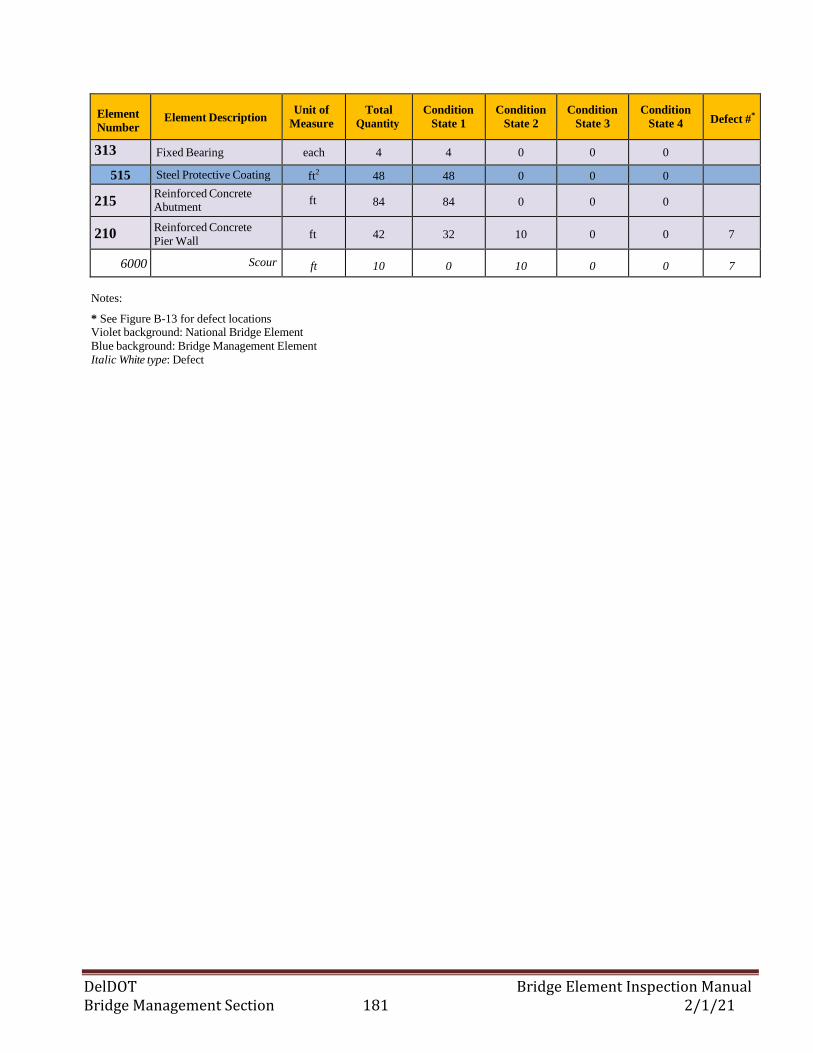
DelDOT Bridge Element Inspection Manual Bridge Management Section 181 2/1/21
Element
Number
Element Description
Unit of
Measure
Total
Quantity
Condition
State 1
Condition
State 2
Condition
State 3
Condition
State 4
Defect #*
313
Fixed Bearing each 4 4 0 0 0
515 Steel Protective Coating ft2 48 48 0 0 0
215 Reinforced Concrete Abutment
ft 84 84 0 0 0
210 Reinforced Concrete
Pier Wall ft 42 32 10 0 0 7
6000 Scour ft 10 0 10 0 0 7
Notes:
* See Figure B-13 for defect locations Violet background: National Bridge Element
Blue background: Bridge Management Element
Italic White type: Defect
DelDOT Bridge Element Inspection Manual Bridge Management Section 182 2/1/21
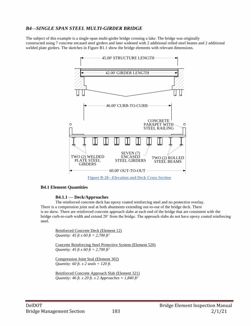
DelDOT Bridge Element Inspection Manual Bridge Management Section 183 2/1/21
B4—SINGLE SPAN STEEL MULTI-GIRDER BRIDGE
The subject of this example is a single-span multi-girder bridge crossing a lake. The bridge was originally
constructed using 7 concrete encased steel girders and later widened with 2 additional rolled steel beams and 2 additional
welded plate girders. The sketches in Figure B1.1 show the bridge elements with relevant dimensions.
45.00' STRUCTURE LENGTH
42.00' GIRDER LENGTH
SEVEN (7) ENCASED
STEEL GIRDERS
60.00' OUT-TO-OUT
46.00' CURB-TO-CURB
TWO (2) ROLLED STEEL BEAMS
TWO (2) WELDED PLATE STEEL
GIRDERS
CONCRETE PARAPET WITH STEEL RAILING
Figure B-20-–Elevation and Deck Cross Section
B4.1 Element Quantities
B4.1.1 — Deck/Approaches The reinforced concrete deck has epoxy coated reinforcing steel and no protective overlay.
There is a compression joint seal at both abutments extending out-to-out of the bridge deck. There
is no skew. There are reinforced concrete approach slabs at each end of the bridge that are consistent with the
bridge curb-to-curb width and extend 20’ from the bridge. The approach slabs do not have epoxy coated reinforcing
steel.
Reinforced Concrete Deck (Element 12)
Quantity: 45 ft x 60 ft = 2,700 ft2
Concrete Reinforcing Steel Protective System (Element 520)
Quantity: 45 ft x 60 ft = 2,700 ft2
Compression Joint Seal (Element 302)
Quantity: 60 ft. x 2 seals = 120 ft.
Reinforced Concrete Approach Slab (Element 321)
Quantity: 46 ft. x 20 ft. x 2 Approaches = 1,840 ft2
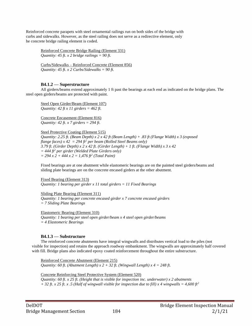
DelDOT Bridge Element Inspection Manual Bridge Management Section 184 2/1/21
Reinforced concrete parapets with steel ornamental railings run on both sides of the bridge with
curbs and sidewalks. However, as the steel railing does not serve as a redirective element, only
he concrete bridge railing element is coded.
Reinforced Concrete Bridge Railing (Element 331)
Quantity: 45 ft. x 2 bridge railings = 90 ft.
Curbs/Sidewalks – Reinforced Concrete (Element 856)
Quantity: 45 ft. x 2 Curbs/Sidewalks = 90 ft.
B4.1.2 — Superstructure
All girders/beams extend approximately 1 ft past the bearings at each end as indicated on the bridge plans. The
steel open girders/beams are protected with paint.
Steel Open Girder/Beam (Element 107)
Quantity: 42 ft x 11 girders = 462 ft.
Concrete Encasement (Element 816)
Quantity: 42 ft. x 7 girders = 294 ft.
Steel Protective Coating (Element 515)
Quantity: 2.25 ft. (Beam Depth) x 2 x 42 ft (Beam Length) + .83 ft (Flange Width) x 3 (exposed
flange faces) x 42 = 294 ft2 per beam (Rolled Steel Beams only)
3.79 ft. (Girder Depth) x 2 x 42 ft. (Girder Length) + 1 ft. (Flange Width) x 3 x 42
= 444 ft2 per girder (Welded Plate Girders only)
= 294 x 2 + 444 x 2 = 1,476 ft2 (Total Paint)
Fixed bearings are at one abutment while elastomeric bearings are on the painted steel girders/beams and
sliding plate bearings are on the concrete encased girders at the other abutment.
Fixed Bearing (Element 313)
Quantity: 1 bearing per girder x 11 total girders = 11 Fixed Bearings
Sliding Plate Bearing (Element 311)
Quantity: 1 bearing per concrete encased girder x 7 concrete encased girders
= 7 Sliding Plate Bearings
Elastomeric Bearing (Element 310)
Quantity: 1 bearing per steel open girder/beam x 4 steel open girder/beams
= 4 Elastomeric Bearings
B4.1.3 — Substructure The reinforced concrete abutments have integral wingwalls and distributes vertical load to the piles (not
visible for inspection) and retains the approach roadway embankment. The wingwalls are approximately half covered
with fill. Bridge plans also indicated epoxy coated reinforcement throughout the entire substructure.
Reinforced Concrete Abutment (Element 215)
Quantity: 60 ft. (Abutment Length) x 2 + 32 ft. (Wingwall Length) x 4 = 248 ft.
Concrete Reinforcing Steel Protective System (Element 520)
Quantity: 60 ft. x 25 ft. (Height that is visible for inspection inc. underwater) x 2 abutments
+ 32 ft. x 25 ft. x .5 (Half of wingwall visible for inspection due to fill) x 4 wingwalls = 4,600 ft2
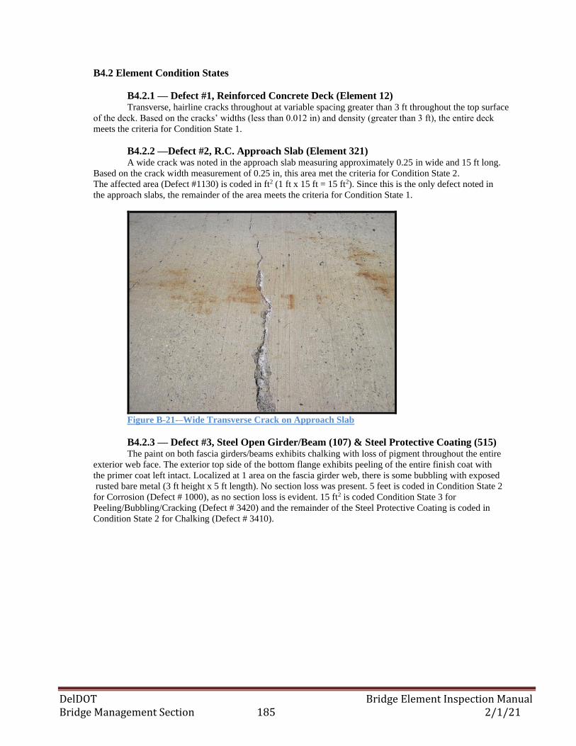
DelDOT Bridge Element Inspection Manual Bridge Management Section 185 2/1/21
B4.2 Element Condition States
B4.2.1 — Defect #1, Reinforced Concrete Deck (Element 12) Transverse, hairline cracks throughout at variable spacing greater than 3 ft throughout the top surface
of the deck. Based on the cracks’ widths (less than 0.012 in) and density (greater than 3 ft), the entire deck
meets the criteria for Condition State 1.
B4.2.2 —Defect #2, R.C. Approach Slab (Element 321) A wide crack was noted in the approach slab measuring approximately 0.25 in wide and 15 ft long.
Based on the crack width measurement of 0.25 in, this area met the criteria for Condition State 2.
The affected area (Defect #1130) is coded in ft2 (1 ft x 15 ft = 15 ft2). Since this is the only defect noted in
the approach slabs, the remainder of the area meets the criteria for Condition State 1.
Figure B-21-–Wide Transverse Crack on Approach Slab
B4.2.3 — Defect #3, Steel Open Girder/Beam (107) & Steel Protective Coating (515) The paint on both fascia girders/beams exhibits chalking with loss of pigment throughout the entire
exterior web face. The exterior top side of the bottom flange exhibits peeling of the entire finish coat with
the primer coat left intact. Localized at 1 area on the fascia girder web, there is some bubbling with exposed
rusted bare metal (3 ft height x 5 ft length). No section loss was present. 5 feet is coded in Condition State 2
for Corrosion (Defect # 1000), as no section loss is evident. 15 ft2 is coded Condition State 3 for
Peeling/Bubbling/Cracking (Defect # 3420) and the remainder of the Steel Protective Coating is coded in
Condition State 2 for Chalking (Defect # 3410).
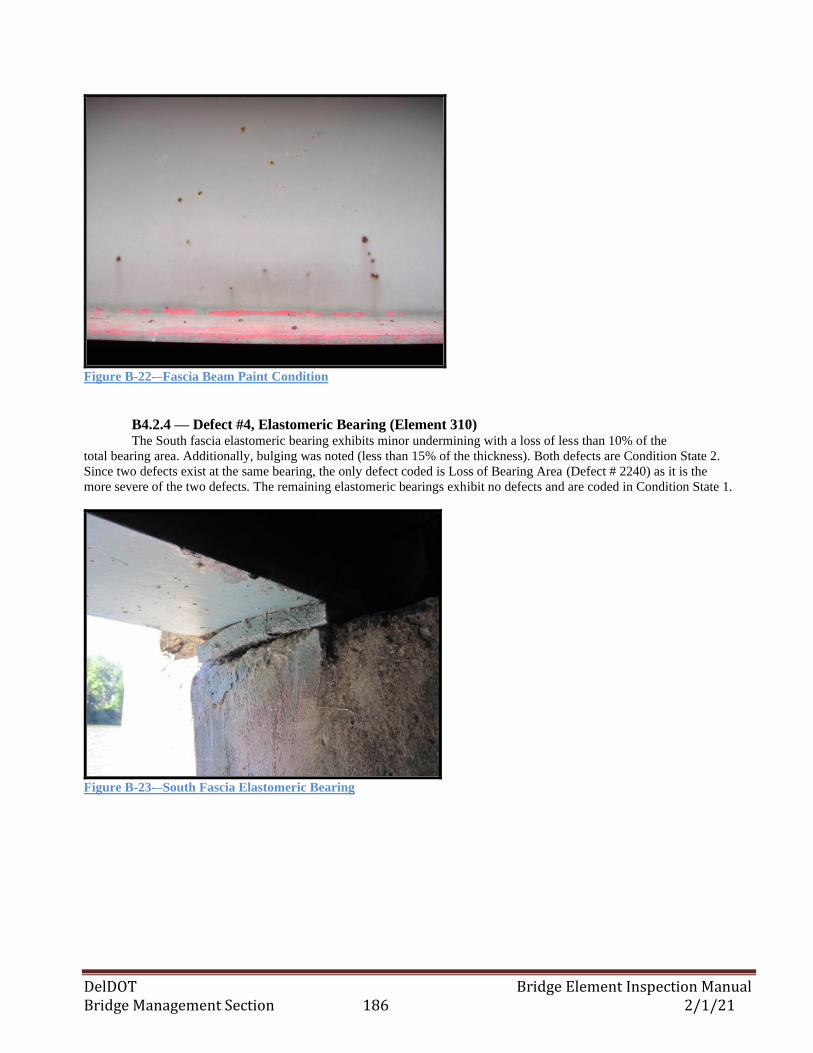
DelDOT Bridge Element Inspection Manual Bridge Management Section 186 2/1/21
Figure B-22-–Fascia Beam Paint Condition
B4.2.4 — Defect #4, Elastomeric Bearing (Element 310) The South fascia elastomeric bearing exhibits minor undermining with a loss of less than 10% of the
total bearing area. Additionally, bulging was noted (less than 15% of the thickness). Both defects are Condition State 2.
Since two defects exist at the same bearing, the only defect coded is Loss of Bearing Area (Defect # 2240) as it is the
more severe of the two defects. The remaining elastomeric bearings exhibit no defects and are coded in Condition State 1.
Figure B-23-–South Fascia Elastomeric Bearing
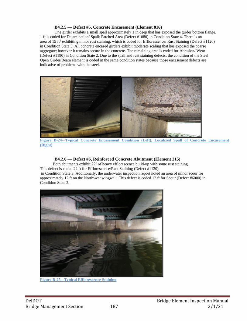
DelDOT Bridge Element Inspection Manual Bridge Management Section 187 2/1/21
B4.2.5 — Defect #5, Concrete Encasement (Element 816) One girder exhibits a small spall approximately 1 in deep that has exposed the girder bottom flange.
1 ft is coded for Delamination/ Spall/ Patched Area (Defect #1080) in Condition State 4. There is an
area of 15 ft2 exhibiting minor rust staining, which is coded for Efflorescence/ Rust Staining (Defect #1120)
in Condition State 3. All concrete encased girders exhibit moderate scaling that has exposed the coarse
aggregate; however it remains secure in the concrete. The remaining area is coded for Abrasion/ Wear
(Defect #1190) in Condition State 2. Due to the spall and rust staining defects, the condition of the Steel
Open Girder/Beam element is coded in the same condition states because those encasement defects are
indicative of problems with the steel.
Figure B-24-–Typical Concrete Encasement Condition (Left), Localized Spall of Concrete Encasement
(Right)
B4.2.6 — Defect #6, Reinforced Concrete Abutment (Element 215) Both abutments exhibit 22’ of heavy efflorescence build-up with some rust staining.
This defect is coded 22 ft for Efflorescence/Rust Staining (Defect #1120)
in Condition State 3. Additionally, the underwater inspection report noted an area of minor scour for
approximately 12 ft on the Northwest wingwall. This defect is coded 12 ft for Scour (Defect #6000) in
Condition State 2.
Figure B-25-–Typical Efflorescence Staining
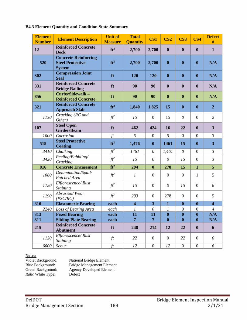
DelDOT Bridge Element Inspection Manual Bridge Management Section 188 2/1/21
B4.3 Element Quantity and Condition State Summary
Element
Number Element Description
Unit of
Measure
Total
Quantity CS1 CS2 CS3 CS4
Defect
#
12 Reinforced Concrete
Deck ft2 2,700 2,700 0 0 0 1
520
Concrete Reinforcing
Steel Protective
System
ft2 2,700 2,700 0 0 0 N/A
302 Compression Joint
Seal ft 120 120 0 0 0 N/A
331 Reinforced Concrete
Bridge Railing ft 90 90 0 0 0 N/A
856 Curbs/Sidewalk –
Reinforced Concrete ft 90 90 0 0 0 N/A
321 Reinforced Concrete
Approach Slab ft2 1,840 1,825 15 0 0 2
1130 Cracking (RC and
Other) ft2 15 0 15 0 0 2
107 Steel Open
Girder/Beam ft 462 424 16 22 0 3
1000 Corrosion ft 5 0 5 0 0 3
515 Steel Protective
Coating ft2 1,476 0 1461 15 0 3
3410 Chalking ft2 1461 0 1,461 0 0 3
3420 Peeling/Bubbling/
Cracking ft2 15 0 0 15 0 3
816 Concrete Encasement ft2 294 0 278 15 1 5
1080 Delamination/Spall/
Patched Area ft2 1 0 0 0 1 5
1120 Efflorescence/ Rust
Staining ft2 15 0 0 15 0 6
1190 Abrasion/ Wear
(PSC/RC) ft2 293 0 278 0 0 5
310 Elastomeric Bearing each 4 3 1 0 0 4
2240 Loss of Bearing Area each 1 0 1 0 0 4
313 Fixed Bearing each 11 11 0 0 0 N/A
311 Sliding Plate Bearing each 7 7 0 0 0 N/A
215 Reinforced Concrete
Abutment ft 248 214 12 22 0 6
1120 Efflorescence/ Rust
Staining ft 22 0 0 22 0 6
6000 Scour ft 12 0 12 0 0 6
Notes:
Violet Background: National Bridge Element
Blue Background: Bridge Management Element
Green Background: Agency Developed Element
Italic White Type: Defect
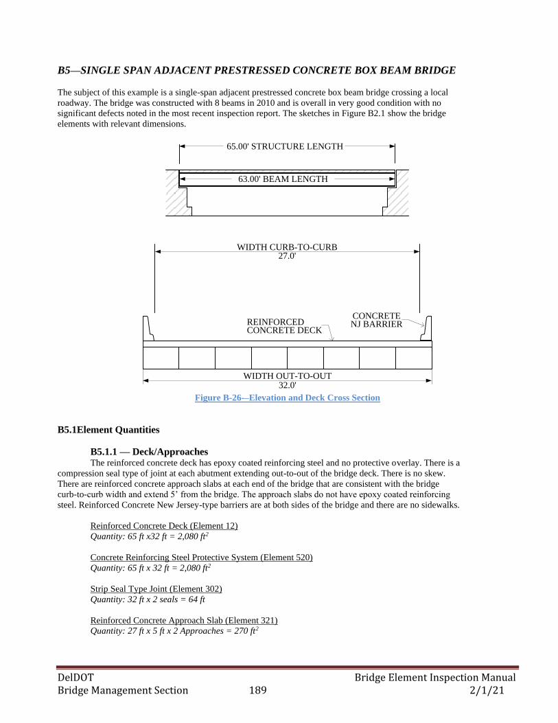
DelDOT Bridge Element Inspection Manual Bridge Management Section 189 2/1/21
B5—SINGLE SPAN ADJACENT PRESTRESSED CONCRETE BOX BEAM BRIDGE
The subject of this example is a single-span adjacent prestressed concrete box beam bridge crossing a local
roadway. The bridge was constructed with 8 beams in 2010 and is overall in very good condition with no
significant defects noted in the most recent inspection report. The sketches in Figure B2.1 show the bridge
elements with relevant dimensions.
65.00' STRUCTURE LENGTH
63.00' BEAM LENGTH
REINFORCEDCONCRETE DECK
WIDTH OUT-TO-OUT
27.0'WIDTH CURB-TO-CURB
32.0'
CONCRETE NJ BARRIER
Figure B-26-–Elevation and Deck Cross Section
B5.1Element Quantities
B5.1.1 — Deck/Approaches The reinforced concrete deck has epoxy coated reinforcing steel and no protective overlay. There is a
compression seal type of joint at each abutment extending out-to-out of the bridge deck. There is no skew.
There are reinforced concrete approach slabs at each end of the bridge that are consistent with the bridge
curb-to-curb width and extend 5’ from the bridge. The approach slabs do not have epoxy coated reinforcing
steel. Reinforced Concrete New Jersey-type barriers are at both sides of the bridge and there are no sidewalks.
Reinforced Concrete Deck (Element 12)
Quantity: 65 ft x32 ft = 2,080 ft2
Concrete Reinforcing Steel Protective System (Element 520)
Quantity: 65 ft x 32 ft = 2,080 ft2
Strip Seal Type Joint (Element 302)
Quantity: 32 ft x 2 seals = 64 ft
Reinforced Concrete Approach Slab (Element 321)
Quantity: 27 ft x 5 ft x 2 Approaches = 270 ft2
DelDOT Bridge Element Inspection Manual Bridge Management Section 190 2/1/21
Reinforced Concrete Bridge Railing (Element 331)
Quantity: 65 ft x 2 bridge railings = 130 ft
B5.1.2 — Superstructure All box beams extend approximately 1 ft past the bearings (elastomeric) at each end as
indicated on the bridge plans. Mild reinforcement steel is coated with epoxy.
Prestressed Concrete Closed Web/Box Girder (Element 104)
Quantity: 63 ft x 8 beams = 504 ft
Elastomeric Bearing (Element 310)
Quantity: 8 beams x 2 bearings per beam = 16 Elastomeric Bearings
Concrete Reinforcing Steel Protective System (Element 520)
Quantity: 63 ft (Beam Length) x 4 ft (Beam Width) x 8 beams + 63 ft x 2.25 ft (Beam
Height) x 2 (Visible Fascia Beam Faces) = 2,300 ft2 – Only visible surfaces are coded
B5.1.3 — Substructure The reinforced concrete abutments have non-integral wingwalls separated from the abutments
by construction joints and distribute vertical load to spread footings (not visible for inspection). Bridge
plans do not indicate epoxy coated reinforcement.
Reinforced Concrete Abutment (Element 215)
Quantity: 40 ft (Abutment Length) x 2 = 80 ft
Wingwalls - Reinforced Concrete (Element 890)
Quantity: 20 ft (Wingwall Length) x 4 = 80 ft
B5.2Element Condition States
B5.2.1 — Defect #1, Reinforced Concrete Deck (Element 12) Transverse, hairline cracks throughout at variable spacing greater than 3 ft throughout the top
surface of the deck. Based on the cracks’ widths (less than 0.012 in) and density (greater than 3 ft), the
entire deck meets the criteria for Condition State 1.
B5.2.2 — Defect #2, Wingwalls – Reinforced Concrete (Element 890) Vertical cracks measuring approximately 1/8” wide with variable spacing between 1.0 ft
and 3.0 ft in the East wingwall for 15 feet length. Based on the cracks’ width between 1/16”-1/4”,
15 ft is coded for Cracking (Defect #1120) in Condition State 2. The
remaining 65ft is coded in Condition State 1.
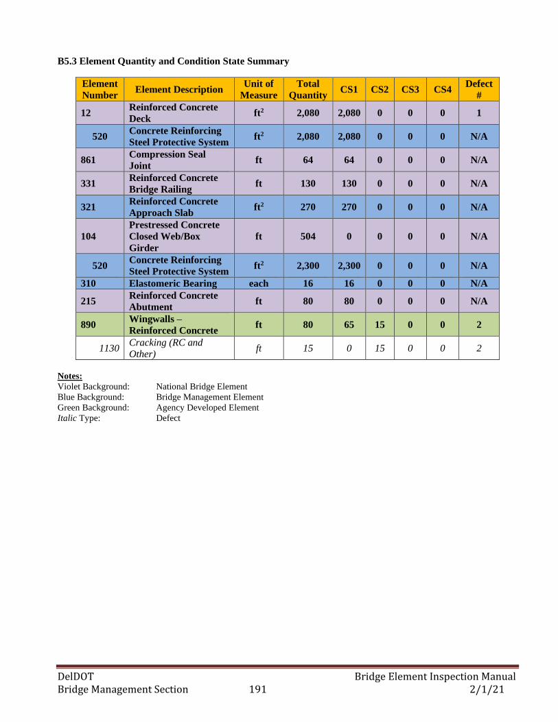
DelDOT Bridge Element Inspection Manual Bridge Management Section 191 2/1/21
B5.3 Element Quantity and Condition State Summary
Element
Number Element Description
Unit of
Measure
Total
Quantity CS1 CS2 CS3 CS4
Defect
#
12 Reinforced Concrete
Deck ft2 2,080 2,080 0 0 0 1
520 Concrete Reinforcing
Steel Protective System ft2 2,080 2,080 0 0 0 N/A
861 Compression Seal
Joint ft 64 64 0 0 0 N/A
331 Reinforced Concrete
Bridge Railing ft 130 130 0 0 0 N/A
321 Reinforced Concrete
Approach Slab ft2 270 270 0 0 0 N/A
104
Prestressed Concrete
Closed Web/Box
Girder
ft 504 0 0 0 0 N/A
520 Concrete Reinforcing
Steel Protective System ft2 2,300 2,300 0 0 0 N/A
310 Elastomeric Bearing each 16 16 0 0 0 N/A
215 Reinforced Concrete
Abutment ft 80 80 0 0 0 N/A
890 Wingwalls –
Reinforced Concrete ft 80 65 15 0 0 2
1130 Cracking (RC and
Other) ft 15 0 15 0 0 2
Notes:
Violet Background: National Bridge Element
Blue Background: Bridge Management Element
Green Background: Agency Developed Element
Italic Type: Defect
DelDOT Bridge Element Inspection Manual Bridge Management Section 192 2/1/21
THIS PAGE INTENTIONALLY LEFT BLANK
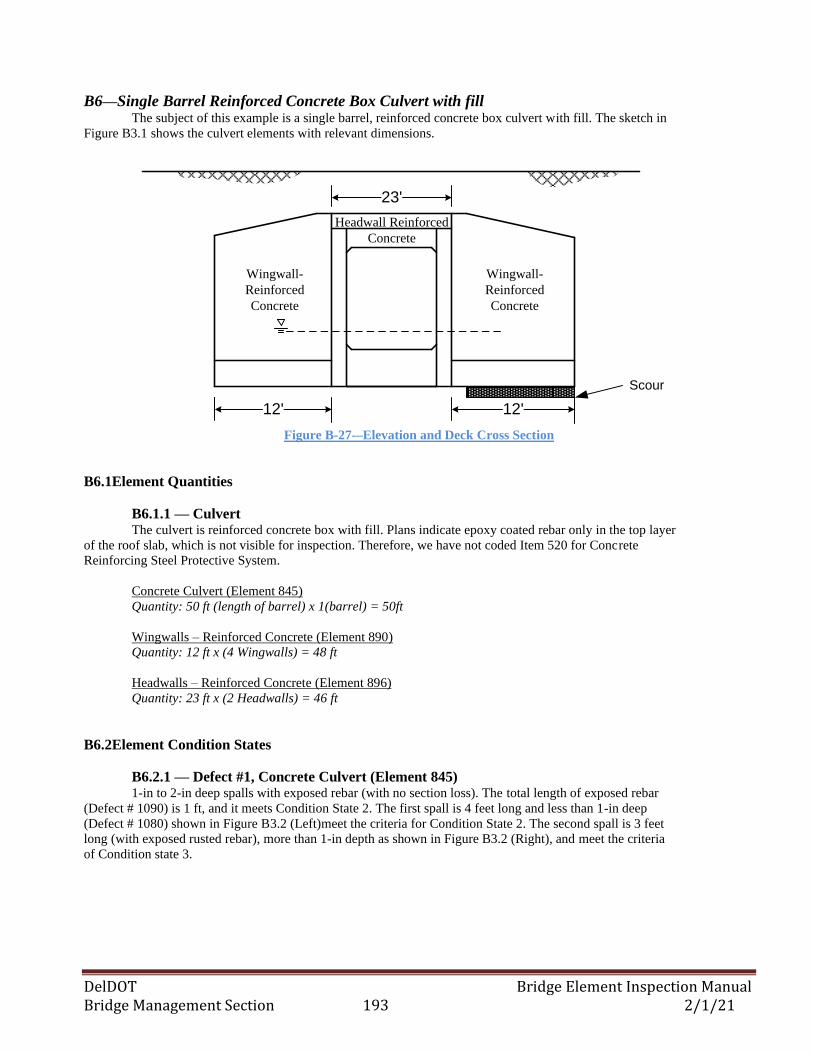
DelDOT Bridge Element Inspection Manual Bridge Management Section 193 2/1/21
B6—Single Barrel Reinforced Concrete Box Culvert with fill The subject of this example is a single barrel, reinforced concrete box culvert with fill. The sketch in
Figure B3.1 shows the culvert elements with relevant dimensions.
Wingwall-
Reinforced
Concrete
12' 12'
23'
Headwall Reinforced
Concrete
Scour
Wingwall-
Reinforced
Concrete
Figure B-27-–Elevation and Deck Cross Section
B6.1Element Quantities
B6.1.1 — Culvert The culvert is reinforced concrete box with fill. Plans indicate epoxy coated rebar only in the top layer
of the roof slab, which is not visible for inspection. Therefore, we have not coded Item 520 for Concrete
Reinforcing Steel Protective System.
Concrete Culvert (Element 845)
Quantity: 50 ft (length of barrel) x 1(barrel) = 50ft
Wingwalls – Reinforced Concrete (Element 890)
Quantity: 12 ft x (4 Wingwalls) = 48 ft
Headwalls – Reinforced Concrete (Element 896)
Quantity: 23 ft x (2 Headwalls) = 46 ft
B6.2Element Condition States
B6.2.1 — Defect #1, Concrete Culvert (Element 845) 1-in to 2-in deep spalls with exposed rebar (with no section loss). The total length of exposed rebar
(Defect # 1090) is 1 ft, and it meets Condition State 2. The first spall is 4 feet long and less than 1-in deep
(Defect # 1080) shown in Figure B3.2 (Left)meet the criteria for Condition State 2. The second spall is 3 feet
long (with exposed rusted rebar), more than 1-in depth as shown in Figure B3.2 (Right), and meet the criteria
of Condition state 3.
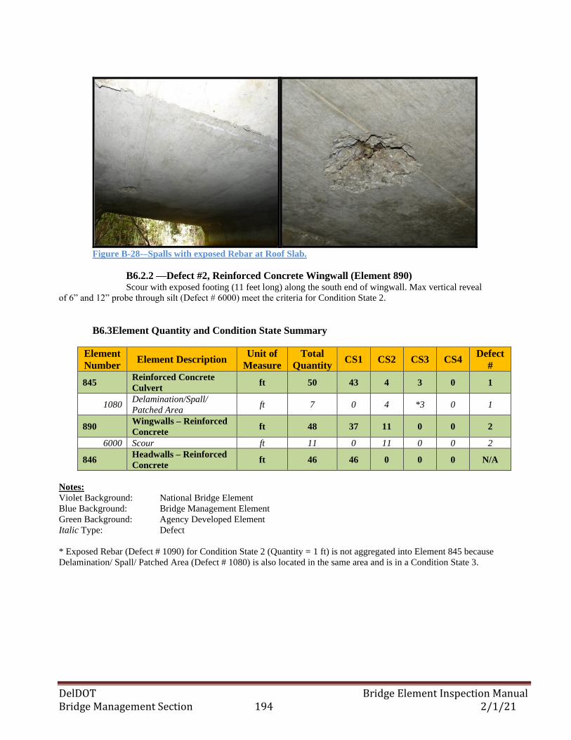
DelDOT Bridge Element Inspection Manual Bridge Management Section 194 2/1/21
Figure B-28-–Spalls with exposed Rebar at Roof Slab.
B6.2.2 —Defect #2, Reinforced Concrete Wingwall (Element 890) Scour with exposed footing (11 feet long) along the south end of wingwall. Max vertical reveal
of 6” and 12” probe through silt (Defect # 6000) meet the criteria for Condition State 2.
B6.3Element Quantity and Condition State Summary
Element
Number Element Description
Unit of
Measure
Total
Quantity CS1 CS2 CS3 CS4
Defect
#
845 Reinforced Concrete
Culvert ft 50 43 4 3 0 1
1080 Delamination/Spall/
Patched Area ft 7 0 4 *3 0 1
890 Wingwalls – Reinforced
Concrete ft 48 37 11 0 0 2
6000 Scour ft 11 0 11 0 0 2
846 Headwalls – Reinforced
Concrete ft 46 46 0 0 0 N/A
Notes:
Violet Background: National Bridge Element
Blue Background: Bridge Management Element
Green Background: Agency Developed Element
Italic Type: Defect
* Exposed Rebar (Defect # 1090) for Condition State 2 (Quantity = 1 ft) is not aggregated into Element 845 because
Delamination/ Spall/ Patched Area (Defect # 1080) is also located in the same area and is in a Condition State 3.
DelDOT Bridge Element Inspection Manual Bridge Management Section 195 2/1/21
APPENDIX C:
ELEMENT GROUPINGS
The charts on the following pages organize the elements defined in Section 3 into National Bridge Elements (NBE’s)
and Bridge Management Elements (BME’s). For each element, the name, identifier, and units of measure are shown and
elements are grouped by major bridge assembly and material type.
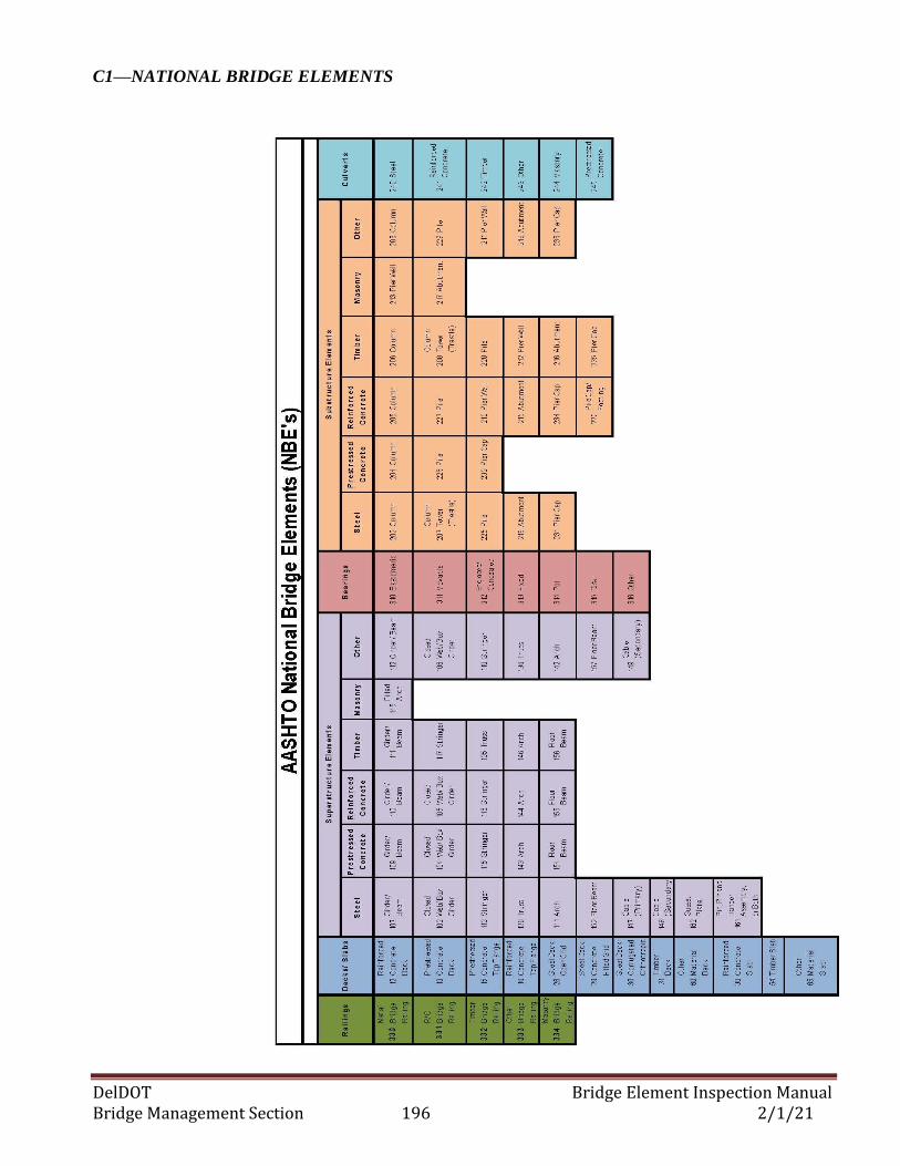
DelDOT Bridge Element Inspection Manual Bridge Management Section 196 2/1/21
C1—NATIONAL BRIDGE ELEMENTS
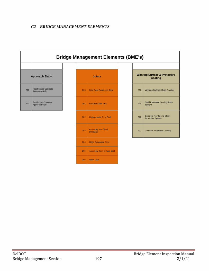
DelDOT Bridge Element Inspection Manual Bridge Management Section 197 2/1/21
C2—BRIDGE MANAGEMENT ELEMENTS
Bridge Management Elements (BME's)
Approach Slabs Joints Wearing Surface & Protective Coating
320 Prestressed Concrete Approach Slab
300 Strip Seal Expansion Joint 510 Wearing Surface: Rigid Overlay
321 Reinforced Concrete Approach Slab
301 Pourable Joint Seal 515 Steel Protective Coating: Paint System
302 Compression Joint Seal 520 Concrete Reinforcing Steel Protective System
303 Assembly Joint/Seal (Modular)
521 Concrete Protective Coating
304 Open Expansion Joint
305 Assembly Joint without Seal
306 Other Joint
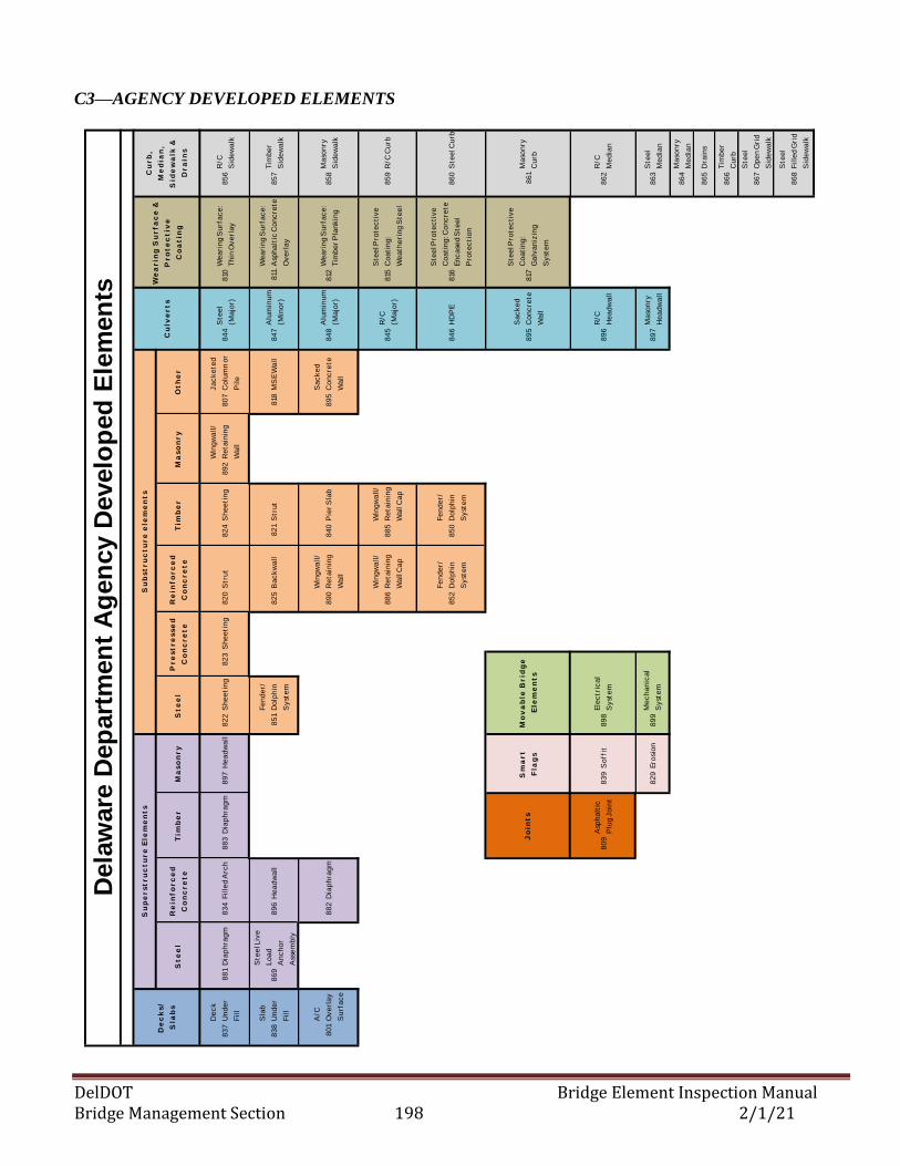
DelDOT Bridge Element Inspection Manual Bridge Management Section 198 2/1/21
C3—AGENCY DEVELOPED ELEMENTS
864 Masonry Median
83
7
De
ck
Un
de
r
Fil
l
88
1D
iap
hra
gm
83
4F
ille
d A
rch
88
3D
iap
hra
gm
89
7H
ea
dw
all
82
2S
he
eti
ng
82
3S
he
eti
ng
82
0S
tru
t8
24
Sh
ee
tin
g8
92
Win
gw
all
/
Re
tain
ing
Wa
ll
80
7
Ja
ck
ete
d
Co
lum
n o
r
Pil
e
84
4S
tee
l
(Ma
jor)
810
We
ari
ng
Su
rfa
ce
:
Th
in O
ve
rla
y8
56
R/C
Sid
ew
alk
83
8
Sla
b
Un
de
r
Fil
l
86
9
Ste
el L
ive
Lo
ad
An
ch
or
Ass
em
bly
89
6H
ea
dw
all
85
1
Fe
nd
er/
Do
lph
in
Sy
ste
m
82
5B
ac
kw
all
82
1S
tru
t8
18M
SE
Wa
ll8
47
Alu
min
um
(Min
or)
811
We
ari
ng
Su
rfa
ce
:
Asp
ha
ltic
Co
nc
rete
Ov
erl
ay
85
7T
imb
er
Sid
ew
alk
80
1
A/C
Ov
erl
ay
Su
rfa
ce
88
2D
iap
hra
gm
89
0
Win
gw
all
/
Re
tain
ing
Wa
ll
84
0P
ier
Sla
b8
95
Sa
ck
ed
Co
nc
rete
Wa
ll
84
8A
lum
inu
m
(Ma
jor)
812
We
ari
ng
Su
rfa
ce
:
Tim
be
r P
lan
kin
g
85
8M
aso
nry
Sid
ew
alk
88
6
Win
gw
all
/
Re
tain
ing
Wa
ll C
ap
88
5
Win
gw
all
/
Re
tain
ing
Wa
ll C
ap
84
5R
/C
(Ma
jor)
815
Ste
el P
rote
cti
ve
Co
ati
ng
:
We
ath
eri
ng
Ste
el
85
9R
/C C
urb
85
2
Fe
nd
er/
Do
lph
in
Sy
ste
m
85
0
Fe
nd
er/
Do
lph
in
Sy
ste
m
84
6H
DP
E8
16
Ste
el P
rote
cti
ve
Co
ati
ng
: Co
nc
rete
En
ca
sed
Ste
el
Pro
tec
tio
n
86
0S
tee
l Cu
rb
89
5
Sa
ck
ed
Co
nc
rete
Wa
ll
817
Ste
el P
rote
cti
ve
Co
ati
ng
:
Ga
lva
niz
ing
Sy
ste
m
86
1M
aso
nry
Cu
rb
80
9A
sph
alt
ic
Plu
g J
oin
t8
39
So
ffit
89
88
96
R/C
He
ad
wa
ll8
62
R/C
Me
dia
n
82
9E
rosi
on
89
98
97
Ma
son
ry
He
ad
wa
ll8
63
Ste
el
Me
dia
n
86
4M
aso
nry
Me
dia
n
86
5D
rain
s
86
6T
imb
er
Cu
rb
86
7
Ste
el
Op
en
Gri
d
Sid
ew
alk
86
8
Ste
el
Fil
led
Gri
d
Sid
ew
alk
St
ee
lS
te
el
Re
inf
or
ce
d
Co
nc
re
te
Tim
be
rM
as
on
ry
Pr
es
tr
es
se
d
Co
nc
re
te
Su
bs
tr
uc
tu
re
ele
me
nt
s
Cu
lve
rt
s
Ot
he
rM
as
on
ry
Re
inf
or
ce
d
Co
nc
re
te
Tim
be
r
Dela
ware
Dep
art
men
t A
gen
cy D
evelo
ped
Ele
men
ts
Ele
ctr
ica
l
Sy
ste
m
Me
ch
an
ica
l
Sy
ste
m
Sm
ar
t
Fla
gs
Mo
va
ble
Br
idg
e
Ele
me
nt
sJ
oin
ts
De
ck
s/
Sla
bs
We
ar
ing
Su
rf
ac
e &
Pr
ot
ec
tiv
e
Co
at
ing
Cu
rb
,
Me
dia
n,
Sid
ew
alk
&
Dr
ain
s
Su
pe
rs
tr
uc
tu
re
Ele
me
nt
s
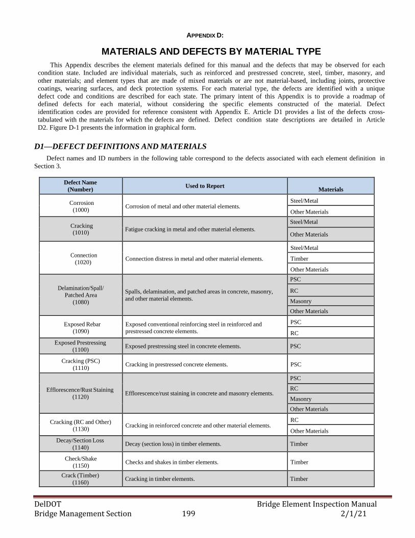
DelDOT Bridge Element Inspection Manual Bridge Management Section 199 2/1/21
837
Deck
Under
Fill
881 Diaphragm 834 Filled Arch 883 Diaphragm 897 Headwall 822 Sheet ing 823 Sheet ing 820 St rut 824 Sheet ing 892
Wingwall/
Ret aining
Wall
807
Jacket ed
Column or
Pile
844St eel
(Major)810
Wearing Surf ace:
Thin Overlay856
R/ C
Sidewalk
838
Slab
Under
Fill
869
St eel Live
Load
Anchor
Assembly
896 Headwall 851
Fender/
Dolphin
Syst em
890
Wingwall/
Ret aining
Wall
821 St rut 818 MSE Wall 847Aluminum
(Minor)811
Wearing Surf ace:
Asphalt ic Concret e
Overlay
857Timber
Sidewalk
801
A/ C
Overlay
Surf ace
882 Diaphragm 886
Wingwall/
Ret aining
Wall Cap
885
Wingwall/
Ret aining
Wall Cap
895
Sacked
Concret e
Wall
848Aluminum
(Major)812
Wearing Surf ace:
Timber Planking 858
Masonry
Sidewalk
852
Fender/
Dolphin
Syst em
850
Fender/
Dolphin
Syst em
845R/ C
(Major)815
St eel Prot ect ive
Coat ing:
Weat hering St eel
859 R/ C Curb
846 HDPE 816
St eel Prot ect ive
Coat ing: Concret e
Encased St eel
Prot ect ion
860 St eel Curb
809Asphalt ic
Plug Joint839 Sof f it 898 895
Sacked
Concret e
Wall
817
St eel Prot ect ive
Coat ing:
Galvanizing
Syst em
861Masonry
Curb
829 Erosion 899 896R/ C
Headwall862
R/ C
Median
897Masonry
Headwall863
St eel
Median
864Masonry
Median
865 Drains
866Timber
Curb
867
St eel
Open Grid
Sidewalk
868
St eel
Filled Grid
Sidewalk
S t e e l S t e e lRe i nf or c e d
Conc r e t eTi mbe r M a sonr y
P r e st r e sse d
Conc r e t e
S ubst r uc t ur e e l e me nt s
Cul v e r t s
Ot he rM a sonr yRe i nf or c e d
Conc r e t eTi mbe r
Delaware Department Agency Developed Elements
Elect r ical
Syst em
Mechanical
Syst em
S ma r t
Fl a gs
M ov a bl e Br i dge
El e me nt sJ oi nt s
De c k s/
S l a bs
We a r i ng S ur f a c e &
P r ot e c t i v e
Coa t i ng
Cur b,
M e di a n,
S i de wa l k &
Dr a i ns
S upe r st r uc t ur e El e me nt s
APPENDIX D:
MATERIALS AND DEFECTS BY MATERIAL TYPE
This Appendix describes the element materials defined for this manual and the defects that may be observed for each
condition state. Included are individual materials, such as reinforced and prestressed concrete, steel, timber, masonry, and
other materials; and element types that are made of mixed materials or are not material-based, including joints, protective
coatings, wearing surfaces, and deck protection systems. For each material type, the defects are identified with a unique
defect code and conditions are described for each state. The primary intent of this Appendix is to provide a roadmap of
defined defects for each material, without considering the specific elements constructed of the material. Defect
identification codes are provided for reference consistent with Appendix E. Article D1 provides a list of the defects cross-
tabulated with the materials for which the defects are defined. Defect condition state descriptions are detailed in Article
D2. Figure D-1 presents the information in graphical form.
D1—DEFECT DEFINITIONS AND MATERIALS
Defect names and ID numbers in the following table correspond to the defects associated with each element definition in
Section 3.
Defect Name
(Number) Used to Report
Materials
Corrosion
(1000) Corrosion of metal and other material elements.
Steel/Metal
Other Materials
Cracking (1010)
Fatigue cracking in metal and other material elements.
Steel/Metal
Other Materials
Connection
(1020) Connection distress in metal and other material elements.
Steel/Metal
Timber
Other Materials
Delamination/Spall/
Patched Area
(1080)
Spalls, delamination, and patched areas in concrete, masonry,
and other material elements.
PSC
RC
Masonry
Other Materials
Exposed Rebar
(1090)
Exposed conventional reinforcing steel in reinforced and
prestressed concrete elements.
PSC
RC
Exposed Prestressing
(1100) Exposed prestressing steel in concrete elements. PSC
Cracking (PSC)
(1110) Cracking in prestressed concrete elements. PSC
Efflorescence/Rust Staining
(1120) Efflorescence/rust staining in concrete and masonry elements.
PSC
RC
Masonry
Other Materials
Cracking (RC and Other)
(1130) Cracking in reinforced concrete and other material elements.
RC
Other Materials
Decay/Section Loss
(1140) Decay (section loss) in timber elements. Timber
Check/Shake
(1150) Checks and shakes in timber elements. Timber
Crack (Timber)
(1160) Cracking in timber elements. Timber
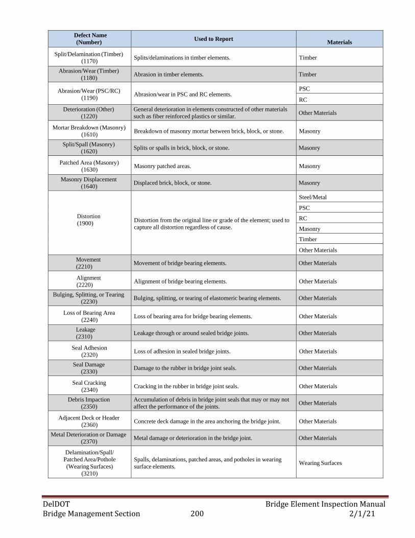
DelDOT Bridge Element Inspection Manual Bridge Management Section 200 2/1/21
Defect Name
(Number) Used to Report
Materials
Split/Delamination (Timber)
(1170) Splits/delaminations in timber elements. Timber
Abrasion/Wear (Timber)
(1180) Abrasion in timber elements. Timber
Abrasion/Wear (PSC/RC)
(1190) Abrasion/wear in PSC and RC elements.
PSC
RC
Deterioration (Other)
(1220)
General deterioration in elements constructed of other materials
such as fiber reinforced plastics or similar. Other Materials
Mortar Breakdown (Masonry)
(1610) Breakdown of masonry mortar between brick, block, or stone. Masonry
Split/Spall (Masonry)
(1620) Splits or spalls in brick, block, or stone. Masonry
Patched Area (Masonry)
(1630) Masonry patched areas. Masonry
Masonry Displacement
(1640) Displaced brick, block, or stone. Masonry
Distortion
(1900)
Distortion from the original line or grade of the element; used to
capture all distortion regardless of cause.
Steel/Metal
PSC
RC
Masonry
Timber
Other Materials
Movement
(2210) Movement of bridge bearing elements. Other Materials
Alignment
(2220) Alignment of bridge bearing elements. Other Materials
Bulging, Splitting, or Tearing
(2230) Bulging, splitting, or tearing of elastomeric bearing elements. Other Materials
Loss of Bearing Area
(2240) Loss of bearing area for bridge bearing elements. Other Materials
Leakage
(2310) Leakage through or around sealed bridge joints. Other Materials
Seal Adhesion
(2320) Loss of adhesion in sealed bridge joints. Other Materials
Seal Damage
(2330) Damage to the rubber in bridge joint seals. Other Materials
Seal Cracking
(2340) Cracking in the rubber in bridge joint seals. Other Materials
Debris Impaction
(2350)
Accumulation of debris in bridge joint seals that may or may not
affect the performance of the joints. Other Materials
Adjacent Deck or Header
(2360) Concrete deck damage in the area anchoring the bridge joint. Other Materials
Metal Deterioration or Damage
(2370) Metal damage or deterioration in the bridge joint. Other Materials
Delamination/Spall/
Patched Area/Pothole
(Wearing Surfaces)
(3210)
Spalls, delaminations, patched areas, and potholes in wearing
surface elements. Wearing Surfaces
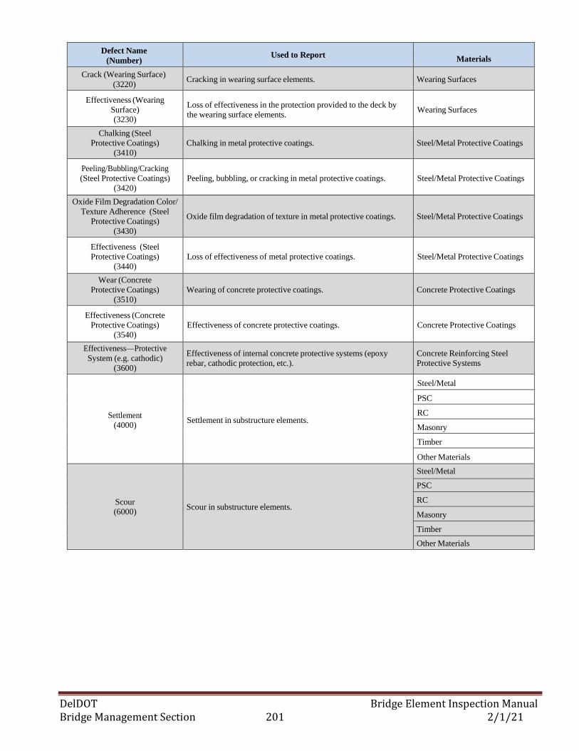
DelDOT Bridge Element Inspection Manual Bridge Management Section 201 2/1/21
Defect Name
(Number) Used to Report
Materials
Crack (Wearing Surface)
(3220) Cracking in wearing surface elements. Wearing Surfaces
Effectiveness (Wearing
Surface) (3230)
Loss of effectiveness in the protection provided to the deck by
the wearing surface elements. Wearing Surfaces
Chalking (Steel
Protective Coatings)
(3410)
Chalking in metal protective coatings. Steel/Metal Protective Coatings
Peeling/Bubbling/Cracking
(Steel Protective Coatings)
(3420)
Peeling, bubbling, or cracking in metal protective coatings. Steel/Metal Protective Coatings
Oxide Film Degradation Color/
Texture Adherence (Steel
Protective Coatings)
(3430)
Oxide film degradation of texture in metal protective coatings. Steel/Metal Protective Coatings
Effectiveness (Steel
Protective Coatings)
(3440)
Loss of effectiveness of metal protective coatings. Steel/Metal Protective Coatings
Wear (Concrete
Protective Coatings)
(3510)
Wearing of concrete protective coatings. Concrete Protective Coatings
Effectiveness (Concrete
Protective Coatings)
(3540)
Effectiveness of concrete protective coatings. Concrete Protective Coatings
Effectiveness—Protective
System (e.g. cathodic)
(3600)
Effectiveness of internal concrete protective systems (epoxy
rebar, cathodic protection, etc.).
Concrete Reinforcing Steel
Protective Systems
Settlement
(4000) Settlement in substructure elements.
Steel/Metal
PSC
RC
Masonry
Timber
Other Materials
Scour
(6000) Scour in substructure elements.
Steel/Metal
PSC
RC
Masonry
Timber
Other Materials
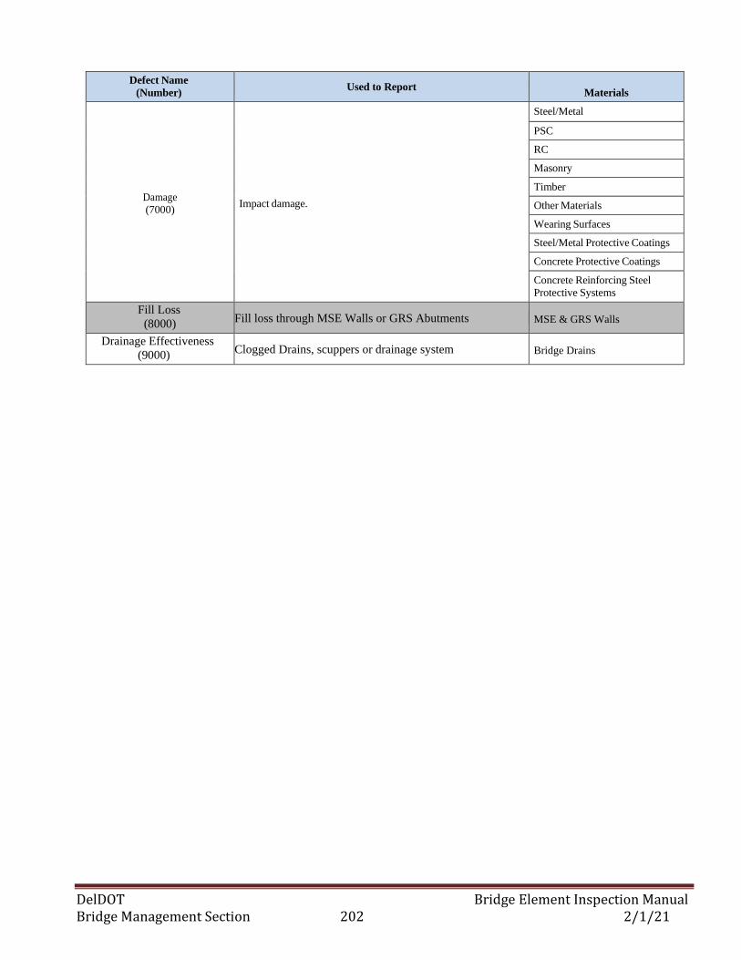
DelDOT Bridge Element Inspection Manual Bridge Management Section 202 2/1/21
Defect Name
(Number) Used to Report
Materials
Damage
(7000)
Impact damage.
Steel/Metal
PSC
RC
Masonry
Timber
Other Materials
Wearing Surfaces
Steel/Metal Protective Coatings
Concrete Protective Coatings
Concrete Reinforcing Steel
Protective Systems
Fill Loss
(8000) Fill loss through MSE Walls or GRS Abutments MSE & GRS Walls
Drainage Effectiveness
(9000) Clogged Drains, scuppers or drainage system Bridge Drains
DelDOT Bridge Element Inspection Manual Bridge Management Section 203 2/1/21
(This page intentionally left blank)
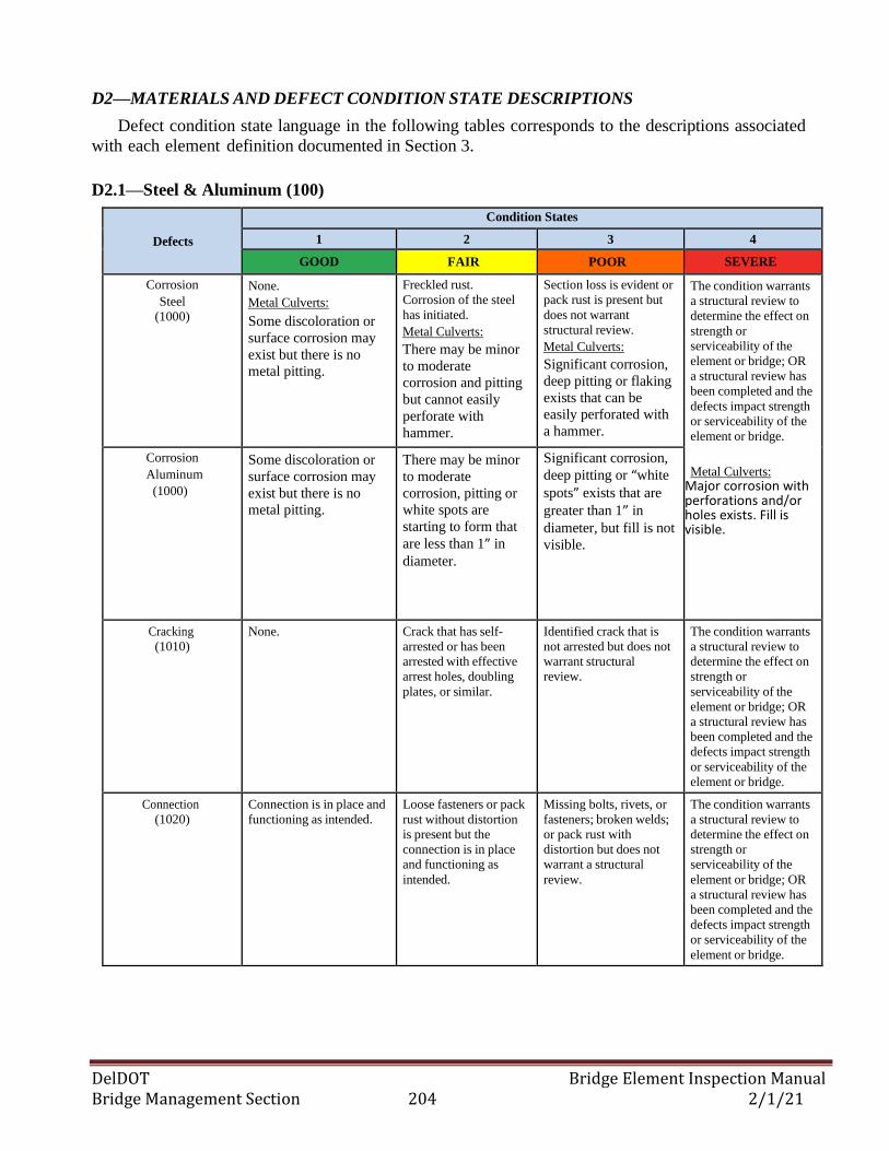
DelDOT Bridge Element Inspection Manual Bridge Management Section 204 2/1/21
D2—MATERIALS AND DEFECT CONDITION STATE DESCRIPTIONS
Defect condition state language in the following tables corresponds to the descriptions associated
with each element definition documented in Section 3.
D2.1—Steel & Aluminum (100)
Defects
Condition States
1 2 3 4
GOOD FAIR POOR SEVERE
Corrosion
Steel
(1000)
None.
Metal Culverts:
Some discoloration or
surface corrosion may
exist but there is no
metal pitting.
Freckled rust.
Corrosion of the steel
has initiated.
Metal Culverts:
There may be minor
to moderate
corrosion and pitting
but cannot easily
perforate with
hammer.
Section loss is evident or
pack rust is present but
does not warrant
structural review.
Metal Culverts:
Significant corrosion,
deep pitting or flaking
exists that can be
easily perforated with
a hammer.
The condition warrants
a structural review to
determine the effect on
strength or
serviceability of the
element or bridge; OR
a structural review has
been completed and the
defects impact strength
or serviceability of the
element or bridge.
Metal Culverts: Major corrosion with perforations and/or holes exists. Fill is visible.
Corrosion
Aluminum
(1000)
Some discoloration or
surface corrosion may
exist but there is no
metal pitting.
There may be minor
to moderate
corrosion, pitting or
white spots are
starting to form that
are less than 1” in
diameter.
Significant corrosion,
deep pitting or “white
spots” exists that are
greater than 1” in
diameter, but fill is not
visible.
Cracking
(1010)
None. Crack that has self-
arrested or has been
arrested with effective
arrest holes, doubling
plates, or similar.
Identified crack that is
not arrested but does not
warrant structural
review.
The condition warrants
a structural review to
determine the effect on
strength or
serviceability of the
element or bridge; OR
a structural review has
been completed and the
defects impact strength
or serviceability of the
element or bridge.
Connection
(1020)
Connection is in place and
functioning as intended.
Loose fasteners or pack
rust without distortion
is present but the
connection is in place
and functioning as
intended.
Missing bolts, rivets, or
fasteners; broken welds;
or pack rust with
distortion but does not
warrant a structural
review.
The condition warrants
a structural review to
determine the effect on
strength or
serviceability of the
element or bridge; OR
a structural review has
been completed and the
defects impact strength
or serviceability of the
element or bridge.
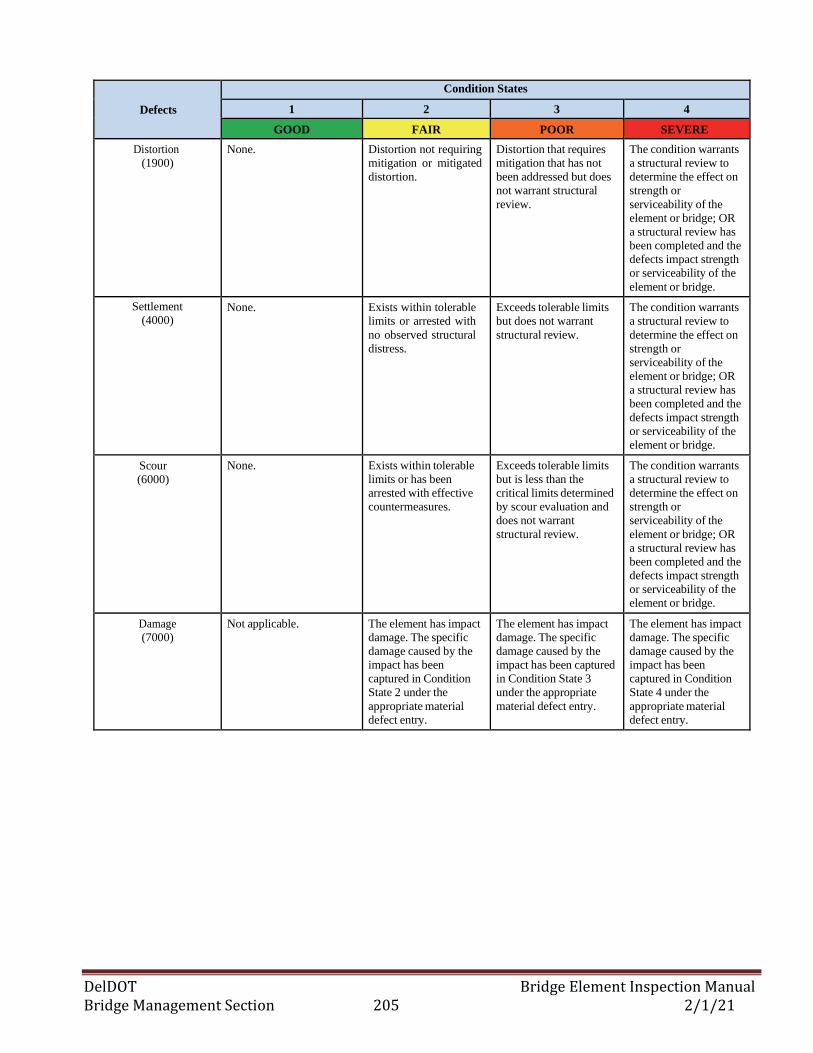
DelDOT Bridge Element Inspection Manual Bridge Management Section 205 2/1/21
Defects
Condition States
1 2 3 4
GOOD FAIR POOR SEVERE
Distortion
(1900)
None. Distortion not requiring
mitigation or mitigated
distortion.
Distortion that requires
mitigation that has not
been addressed but does
not warrant structural
review.
The condition warrants
a structural review to
determine the effect on
strength or
serviceability of the
element or bridge; OR
a structural review has
been completed and the
defects impact strength
or serviceability of the
element or bridge.
Settlement
(4000) None. Exists within tolerable
limits or arrested with
no observed structural
distress.
Exceeds tolerable limits
but does not warrant
structural review.
The condition warrants
a structural review to
determine the effect on
strength or
serviceability of the
element or bridge; OR
a structural review has
been completed and the
defects impact strength
or serviceability of the
element or bridge.
Scour
(6000)
None. Exists within tolerable
limits or has been
arrested with effective
countermeasures.
Exceeds tolerable limits
but is less than the
critical limits determined
by scour evaluation and
does not warrant
structural review.
The condition warrants
a structural review to
determine the effect on
strength or
serviceability of the
element or bridge; OR
a structural review has
been completed and the
defects impact strength
or serviceability of the
element or bridge.
Damage
(7000)
Not applicable. The element has impact
damage. The specific
damage caused by the
impact has been
captured in Condition
State 2 under the
appropriate material
defect entry.
The element has impact
damage. The specific
damage caused by the
impact has been captured
in Condition State 3
under the appropriate
material defect entry.
The element has impact
damage. The specific
damage caused by the
impact has been
captured in Condition
State 4 under the
appropriate material
defect entry.
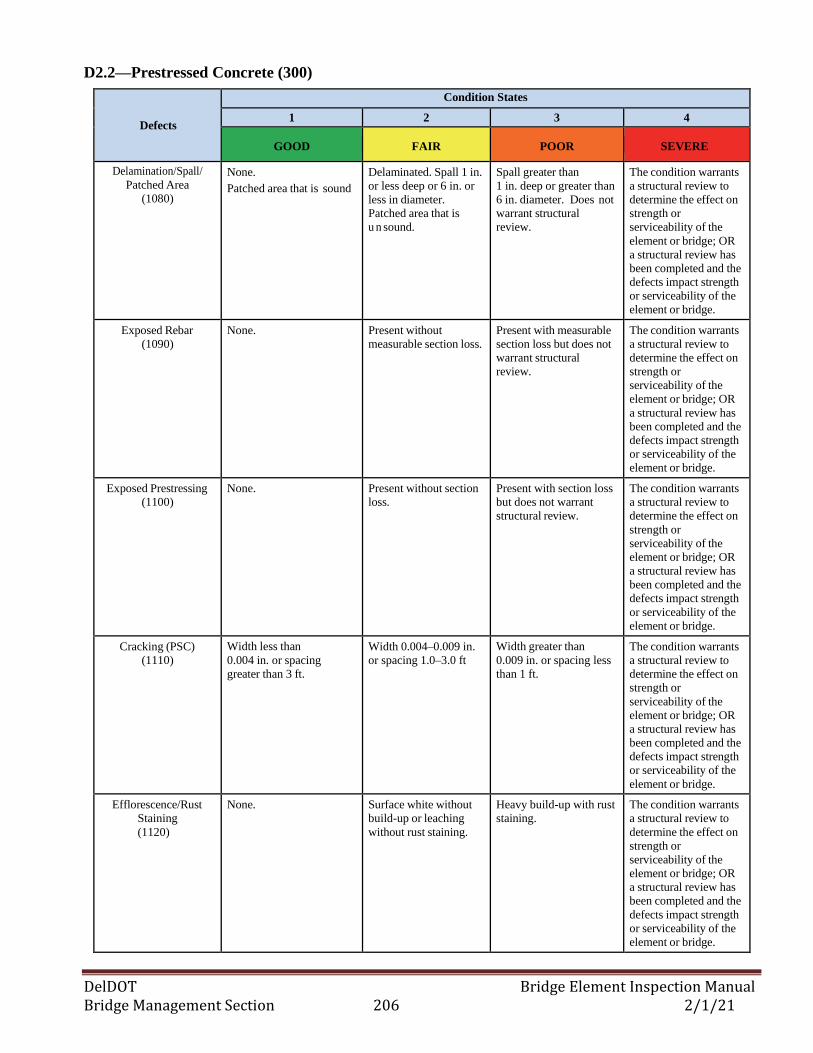
DelDOT Bridge Element Inspection Manual Bridge Management Section 206 2/1/21
D2.2—Prestressed Concrete (300)
Defects
Condition States
1 2 3 4
GOOD FAIR POOR SEVERE
Delamination/Spall/
Patched Area
(1080)
None.
Patched area that is sound
Delaminated. Spall 1 in.
or less deep or 6 in. or
less in diameter.
Patched area that is
u n sound.
Spall greater than
1 in. deep or greater than
6 in. diameter. Does not
warrant structural
review.
The condition warrants
a structural review to
determine the effect on
strength or
serviceability of the
element or bridge; OR
a structural review has
been completed and the
defects impact strength
or serviceability of the
element or bridge.
Exposed Rebar
(1090)
None. Present without
measurable section loss.
Present with measurable
section loss but does not
warrant structural
review.
The condition warrants
a structural review to
determine the effect on
strength or
serviceability of the
element or bridge; OR
a structural review has
been completed and the
defects impact strength
or serviceability of the
element or bridge.
Exposed Prestressing
(1100)
None. Present without section
loss.
Present with section loss
but does not warrant
structural review.
The condition warrants
a structural review to
determine the effect on
strength or
serviceability of the
element or bridge; OR
a structural review has
been completed and the
defects impact strength
or serviceability of the
element or bridge.
Cracking (PSC)
(1110)
Width less than
0.004 in. or spacing
greater than 3 ft.
Width 0.004–0.009 in.
or spacing 1.0–3.0 ft
Width greater than
0.009 in. or spacing less
than 1 ft.
The condition warrants
a structural review to
determine the effect on
strength or
serviceability of the
element or bridge; OR
a structural review has
been completed and the
defects impact strength
or serviceability of the
element or bridge.
Efflorescence/Rust
Staining
(1120)
None. Surface white without
build-up or leaching
without rust staining.
Heavy build-up with rust
staining.
The condition warrants
a structural review to
determine the effect on
strength or
serviceability of the
element or bridge; OR
a structural review has
been completed and the
defects impact strength
or serviceability of the
element or bridge.
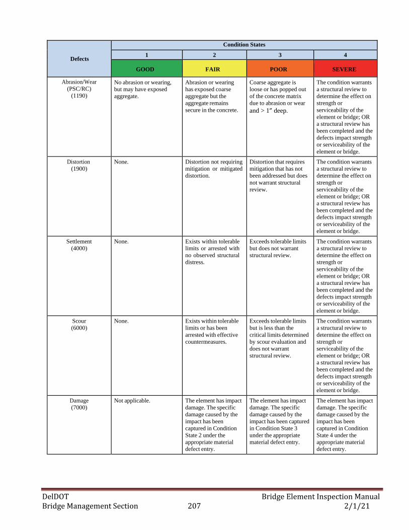
DelDOT Bridge Element Inspection Manual Bridge Management Section 207 2/1/21
Defects
Condition States
1 2 3 4
GOOD FAIR POOR SEVERE
Abrasion/Wear
(PSC/RC)
(1190)
No abrasion or wearing,
but may have exposed
aggregate.
Abrasion or wearing
has exposed coarse
aggregate but the
aggregate remains
secure in the concrete.
Coarse aggregate is
loose or has popped out
of the concrete matrix
due to abrasion or wear
and > 1” deep.
The condition warrants
a structural review to
determine the effect on
strength or
serviceability of the
element or bridge; OR
a structural review has
been completed and the
defects impact strength
or serviceability of the
element or bridge.
Distortion
(1900)
None. Distortion not requiring
mitigation or mitigated
distortion.
Distortion that requires
mitigation that has not
been addressed but does
not warrant structural
review.
The condition warrants
a structural review to
determine the effect on
strength or
serviceability of the
element or bridge; OR
a structural review has
been completed and the
defects impact strength
or serviceability of the
element or bridge.
Settlement
(4000)
None. Exists within tolerable
limits or arrested with
no observed structural
distress.
Exceeds tolerable limits
but does not warrant
structural review.
The condition warrants
a structural review to
determine the effect on
strength or
serviceability of the
element or bridge; OR
a structural review has
been completed and the
defects impact strength
or serviceability of the
element or bridge.
Scour
(6000)
None. Exists within tolerable
limits or has been
arrested with effective
countermeasures.
Exceeds tolerable limits
but is less than the
critical limits determined
by scour evaluation and
does not warrant
structural review.
The condition warrants
a structural review to
determine the effect on
strength or
serviceability of the
element or bridge; OR
a structural review has
been completed and the
defects impact strength
or serviceability of the
element or bridge.
Damage
(7000)
Not applicable. The element has impact
damage. The specific
damage caused by the
impact has been
captured in Condition
State 2 under the
appropriate material
defect entry.
The element has impact
damage. The specific
damage caused by the
impact has been captured
in Condition State 3
under the appropriate
material defect entry.
The element has impact
damage. The specific
damage caused by the
impact has been
captured in Condition
State 4 under the
appropriate material
defect entry.
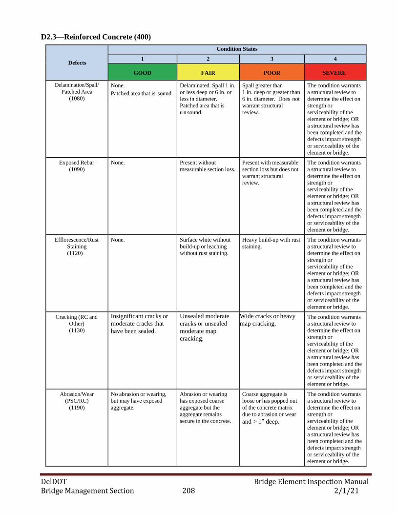
DelDOT Bridge Element Inspection Manual Bridge Management Section 208 2/1/21
D2.3—Reinforced Concrete (400)
Defects
Condition States
1 2 3 4
GOOD FAIR POOR SEVERE
Delamination/Spall/
Patched Area
(1080)
None.
Patched area that is sound.
Delaminated. Spall 1 in.
or less deep or 6 in. or
less in diameter.
Patched area that is
u n sound.
Spall greater than
1 in. deep or greater than
6 in. diameter. Does not
warrant structural
review.
The condition warrants
a structural review to
determine the effect on
strength or
serviceability of the
element or bridge; OR
a structural review has
been completed and the
defects impact strength
or serviceability of the
element or bridge.
Exposed Rebar
(1090)
None. Present without
measurable section loss.
Present with measurable
section loss but does not
warrant structural
review.
The condition warrants
a structural review to
determine the effect on
strength or
serviceability of the
element or bridge; OR
a structural review has
been completed and the
defects impact strength
or serviceability of the
element or bridge.
Efflorescence/Rust
Staining
(1120)
None. Surface white without
build-up or leaching
without rust staining.
Heavy build-up with rust
staining.
The condition warrants
a structural review to
determine the effect on
strength or
serviceability of the
element or bridge; OR
a structural review has
been completed and the
defects impact strength
or serviceability of the
element or bridge.
Cracking (RC and
Other)
(1130)
Insignificant cracks or
moderate cracks that
have been sealed.
Unsealed moderate
cracks or unsealed
moderate map
cracking.
Wide cracks or heavy
map cracking. The condition warrants
a structural review to
determine the effect on
strength or
serviceability of the
element or bridge; OR
a structural review has
been completed and the
defects impact strength
or serviceability of the
element or bridge.
Abrasion/Wear
(PSC/RC)
(1190)
No abrasion or wearing,
but may have exposed
aggregate.
Abrasion or wearing
has exposed coarse
aggregate but the
aggregate remains
secure in the concrete.
Coarse aggregate is
loose or has popped out
of the concrete matrix
due to abrasion or wear
and > 1” deep.
The condition warrants
a structural review to
determine the effect on
strength or
serviceability of the
element or bridge; OR
a structural review has
been completed and the
defects impact strength
or serviceability of the
element or bridge.
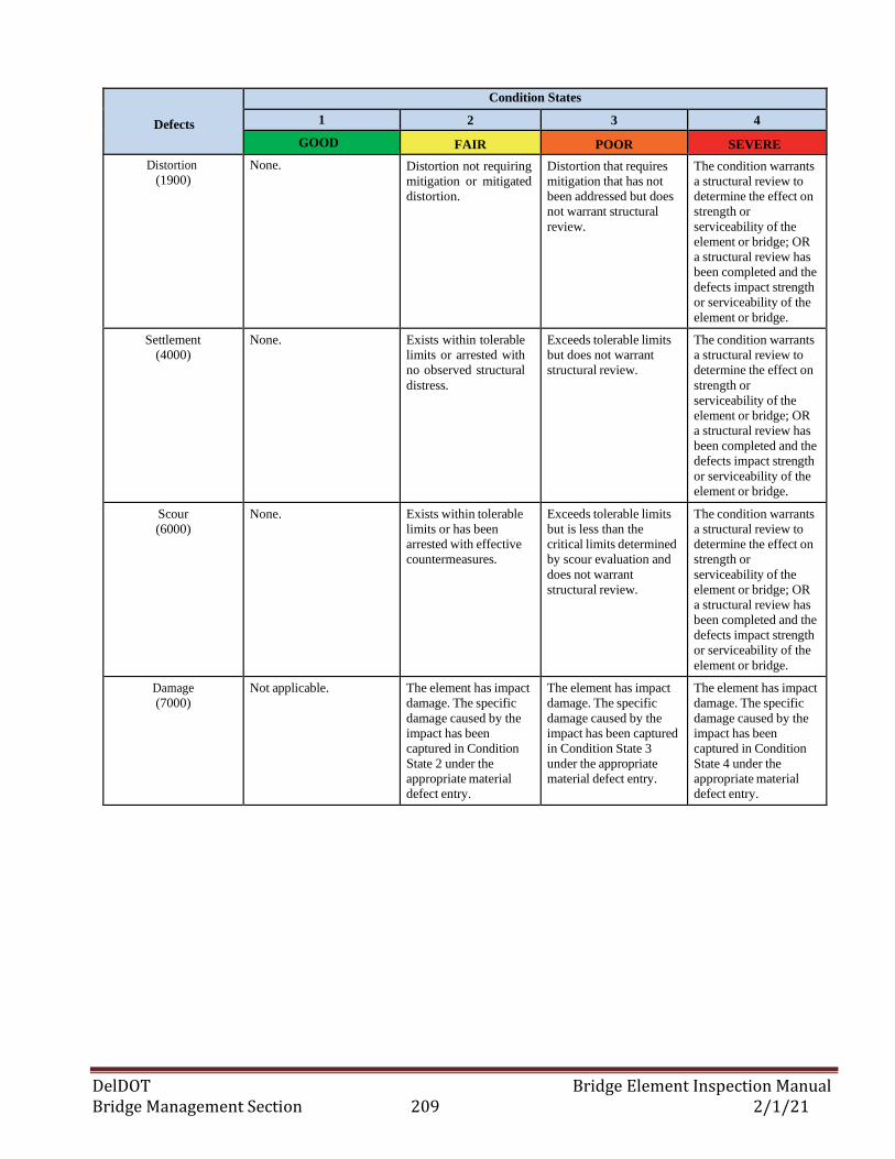
DelDOT Bridge Element Inspection Manual Bridge Management Section 209 2/1/21
Defects
Condition States
1 2 3 4
GOOD FAIR POOR SEVERE
Distortion
(1900)
None. Distortion not requiring
mitigation or mitigated
distortion.
Distortion that requires
mitigation that has not
been addressed but does
not warrant structural
review.
The condition warrants
a structural review to
determine the effect on
strength or
serviceability of the
element or bridge; OR
a structural review has
been completed and the
defects impact strength
or serviceability of the
element or bridge.
Settlement
(4000)
None. Exists within tolerable
limits or arrested with
no observed structural
distress.
Exceeds tolerable limits
but does not warrant
structural review.
The condition warrants
a structural review to
determine the effect on
strength or
serviceability of the
element or bridge; OR
a structural review has
been completed and the
defects impact strength
or serviceability of the
element or bridge.
Scour
(6000)
None. Exists within tolerable
limits or has been
arrested with effective
countermeasures.
Exceeds tolerable limits
but is less than the
critical limits determined
by scour evaluation and
does not warrant
structural review.
The condition warrants
a structural review to
determine the effect on
strength or
serviceability of the
element or bridge; OR
a structural review has
been completed and the
defects impact strength
or serviceability of the
element or bridge.
Damage
(7000)
Not applicable. The element has impact
damage. The specific
damage caused by the
impact has been
captured in Condition
State 2 under the
appropriate material
defect entry.
The element has impact
damage. The specific
damage caused by the
impact has been captured
in Condition State 3
under the appropriate
material defect entry.
The element has impact
damage. The specific
damage caused by the
impact has been
captured in Condition
State 4 under the
appropriate material
defect entry.
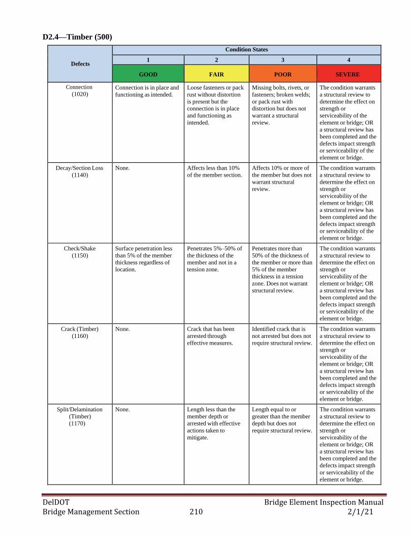
DelDOT Bridge Element Inspection Manual Bridge Management Section 210 2/1/21
D2.4—Timber (500)
Defects
Condition States
1 2 3 4
GOOD FAIR POOR SEVERE
Connection
(1020) Connection is in place and
functioning as intended.
Loose fasteners or pack
rust without distortion
is present but the
connection is in place
and functioning as
intended.
Missing bolts, rivets, or
fasteners; broken welds;
or pack rust with
distortion but does not
warrant a structural
review.
The condition warrants
a structural review to
determine the effect on
strength or
serviceability of the
element or bridge; OR
a structural review has
been completed and the
defects impact strength
or serviceability of the
element or bridge.
Decay/Section Loss
(1140)
None. Affects less than 10%
of the member section.
Affects 10% or more of
the member but does not
warrant structural
review.
The condition warrants
a structural review to
determine the effect on
strength or
serviceability of the
element or bridge; OR
a structural review has
been completed and the
defects impact strength
or serviceability of the
element or bridge.
Check/Shake
(1150)
Surface penetration less
than 5% of the member
thickness regardless of
location.
Penetrates 5%–50% of
the thickness of the
member and not in a
tension zone.
Penetrates more than
50% of the thickness of
the member or more than
5% of the member
thickness in a tension
zone. Does not warrant
structural review.
The condition warrants
a structural review to
determine the effect on
strength or
serviceability of the
element or bridge; OR
a structural review has
been completed and the
defects impact strength
or serviceability of the
element or bridge.
Crack (Timber)
(1160)
None. Crack that has been
arrested through
effective measures.
Identified crack that is
not arrested but does not
require structural review.
The condition warrants
a structural review to
determine the effect on
strength or
serviceability of the
element or bridge; OR
a structural review has
been completed and the
defects impact strength
or serviceability of the
element or bridge.
Split/Delamination
(Timber)
(1170)
None. Length less than the
member depth or
arrested with effective
actions taken to
mitigate.
Length equal to or
greater than the member
depth but does not
require structural review.
The condition warrants
a structural review to
determine the effect on
strength or
serviceability of the
element or bridge; OR
a structural review has
been completed and the
defects impact strength
or serviceability of the
element or bridge.
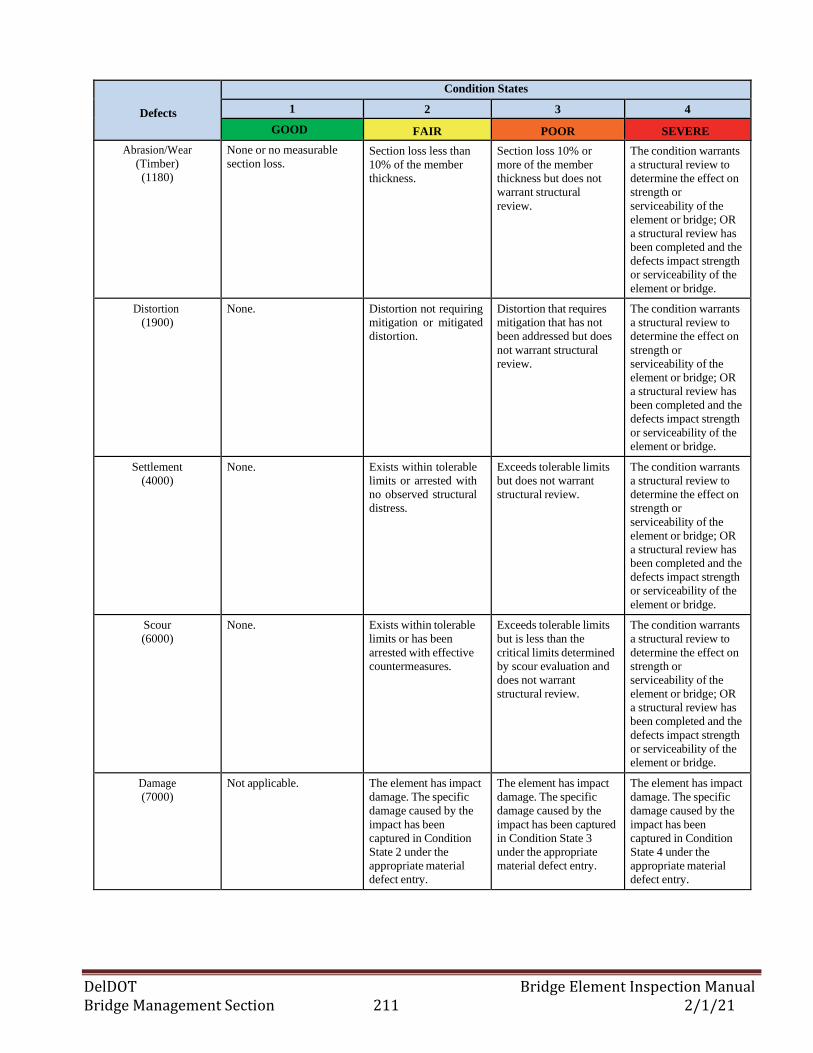
DelDOT Bridge Element Inspection Manual Bridge Management Section 211 2/1/21
Defects
Condition States
1 2 3 4
GOOD FAIR POOR SEVERE
Abrasion/Wear
(Timber)
(1180)
None or no measurable
section loss. Section loss less than
10% of the member
thickness.
Section loss 10% or
more of the member
thickness but does not
warrant structural
review.
The condition warrants
a structural review to
determine the effect on
strength or
serviceability of the
element or bridge; OR
a structural review has
been completed and the
defects impact strength
or serviceability of the
element or bridge.
Distortion
(1900)
None. Distortion not requiring
mitigation or mitigated
distortion.
Distortion that requires
mitigation that has not
been addressed but does
not warrant structural
review.
The condition warrants
a structural review to
determine the effect on
strength or
serviceability of the
element or bridge; OR
a structural review has
been completed and the
defects impact strength
or serviceability of the
element or bridge.
Settlement
(4000)
None. Exists within tolerable
limits or arrested with
no observed structural
distress.
Exceeds tolerable limits
but does not warrant
structural review.
The condition warrants
a structural review to
determine the effect on
strength or
serviceability of the
element or bridge; OR
a structural review has
been completed and the
defects impact strength
or serviceability of the
element or bridge.
Scour
(6000)
None. Exists within tolerable
limits or has been
arrested with effective
countermeasures.
Exceeds tolerable limits
but is less than the
critical limits determined
by scour evaluation and
does not warrant
structural review.
The condition warrants
a structural review to
determine the effect on
strength or
serviceability of the
element or bridge; OR
a structural review has
been completed and the
defects impact strength
or serviceability of the
element or bridge.
Damage
(7000)
Not applicable. The element has impact
damage. The specific
damage caused by the
impact has been
captured in Condition
State 2 under the
appropriate material
defect entry.
The element has impact
damage. The specific
damage caused by the
impact has been captured
in Condition State 3
under the appropriate
material defect entry.
The element has impact
damage. The specific
damage caused by the
impact has been
captured in Condition
State 4 under the
appropriate material
defect entry.
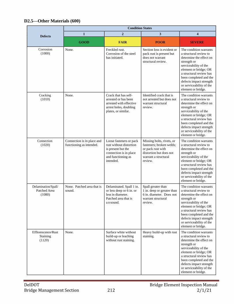
DelDOT Bridge Element Inspection Manual Bridge Management Section 212 2/1/21
D2.5—Other Materials (600)
Defects
Condition States
1 2 3 4
GOOD FAIR POOR SEVERE
Corrosion
(1000) None. Freckled rust.
Corrosion of the steel
has initiated.
Section loss is evident or
pack rust is present but
does not warrant
structural review.
The condition warrants
a structural review to
determine the effect on
strength or
serviceability of the
element or bridge; OR
a structural review has
been completed and the
defects impact strength
or serviceability of the
element or bridge.
Cracking
(1010)
None. Crack that has self-
arrested or has been
arrested with effective
arrest holes, doubling
plates, or similar.
Identified crack that is
not arrested but does not
warrant structural
review.
The condition warrants
a structural review to
determine the effect on
strength or
serviceability of the
element or bridge; OR
a structural review has
been completed and the
defects impact strength
or serviceability of the
element or bridge.
Connection
(1020)
Connection is in place and
functioning as intended.
Loose fasteners or pack
rust without distortion
is present but the
connection is in place
and functioning as
intended.
Missing bolts, rivets, or
fasteners; broken welds;
or pack rust with
distortion but does not
warrant a structural
review.
The condition warrants
a structural review to
determine the effect on
strength or
serviceability of the
element or bridge; OR
a structural review has
been completed and the
defects impact strength
or serviceability of the
element or bridge.
Delamination/Spall/
Patched Area
(1080)
None. Patched area that is
sound.
Delaminated. Spall 1 in.
or less deep or 6 in. or
less in diameter.
Patched area that is
u n sound.
Spall greater than
1 in. deep or greater than
6 in. diameter. Does not
warrant structural
review.
The condition warrants
a structural review to
determine the effect on
strength or
serviceability of the
element or bridge; OR
a structural review has
been completed and the
defects impact strength
or serviceability of the
element or bridge.
Efflorescence/Rust
Staining
(1120)
None. Surface white without
build-up or leaching
without rust staining.
Heavy build-up with rust
staining.
The condition warrants
a structural review to
determine the effect on
strength or
serviceability of the
element or bridge; OR
a structural review has
been completed and the
defects impact strength
or serviceability of the
element or bridge.
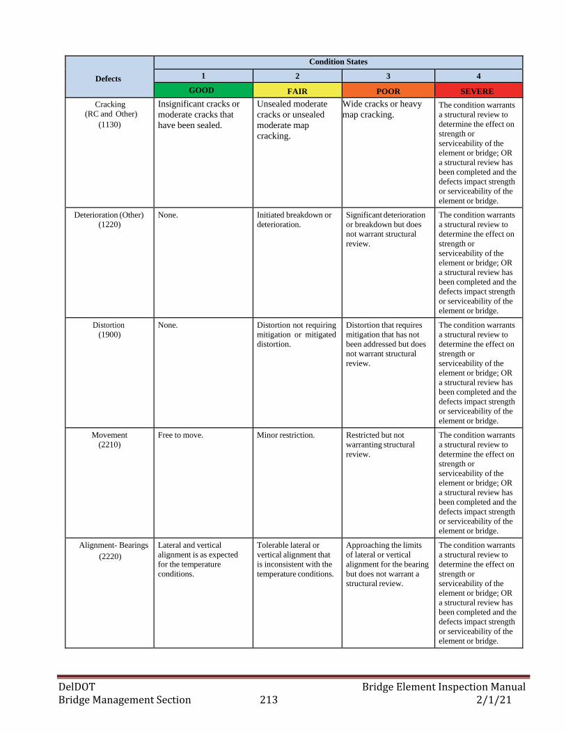
DelDOT Bridge Element Inspection Manual Bridge Management Section 213 2/1/21
Defects
Condition States
1 2 3 4
GOOD FAIR POOR SEVERE
Cracking
(RC and Other)
(1130)
Insignificant cracks or
moderate cracks that
have been sealed.
Unsealed moderate
cracks or unsealed
moderate map
cracking.
Wide cracks or heavy
map cracking. The condition warrants
a structural review to
determine the effect on
strength or
serviceability of the
element or bridge; OR
a structural review has
been completed and the
defects impact strength
or serviceability of the
element or bridge.
Deterioration (Other)
(1220)
None. Initiated breakdown or
deterioration.
Significant deterioration
or breakdown but does
not warrant structural
review.
The condition warrants
a structural review to
determine the effect on
strength or
serviceability of the
element or bridge; OR
a structural review has
been completed and the
defects impact strength
or serviceability of the
element or bridge.
Distortion
(1900)
None. Distortion not requiring
mitigation or mitigated
distortion.
Distortion that requires
mitigation that has not
been addressed but does
not warrant structural
review.
The condition warrants
a structural review to
determine the effect on
strength or
serviceability of the
element or bridge; OR
a structural review has
been completed and the
defects impact strength
or serviceability of the
element or bridge.
Movement
(2210)
Free to move. Minor restriction. Restricted but not
warranting structural
review.
The condition warrants
a structural review to
determine the effect on
strength or
serviceability of the
element or bridge; OR
a structural review has
been completed and the
defects impact strength
or serviceability of the
element or bridge.
Alignment- Bearings
(2220)
Lateral and vertical
alignment is as expected
for the temperature
conditions.
Tolerable lateral or
vertical alignment that
is inconsistent with the
temperature conditions.
Approaching the limits
of lateral or vertical
alignment for the bearing
but does not warrant a
structural review.
The condition warrants
a structural review to
determine the effect on
strength or
serviceability of the
element or bridge; OR
a structural review has
been completed and the
defects impact strength
or serviceability of the
element or bridge.
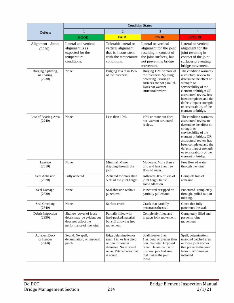
DelDOT Bridge Element Inspection Manual Bridge Management Section 214 2/1/21
Defects
Condition States
1 2 3 4
GOOD FAIR POOR SEVERE
Alignment - Joints
(2220)
Lateral and vertical
alignment is as
expected for the
temperature
conditions.
Tolerable lateral or
vertical alignment
that is inconsistent
with the temperature
conditions.
Lateral or vertical
alignment for the joint
resulting in contact of
the joint surfaces, but
not preventing bridge
movement.
Lateral or vertical
alignment for the
joint resulting in
contact of the joint
surfaces preventing
bridge movement.
Bulging, Splitting,
or Tearing
(2230)
None. Bulging less than 15%
of the thickness.
Bulging 15% or more of
the thickness. Splitting
or tearing. Bearing's
surfaces are not parallel.
Does not warrant
structural review.
The condition warrants
a structural review to
determine the effect on
strength or
serviceability of the
element or bridge; OR
a structural review has
been completed and the
defects impact strength
or serviceability of the
element or bridge.
Loss of Bearing Area
(2240)
None. Less than 10%. 10% or more but does
not warrant structural
review.
The condition warrants
a structural review to
determine the effect on
strength or
serviceability of the
element or bridge; OR
a structural review has
been completed and the
defects impact strength
or serviceability of the
element or bridge.
Leakage
(2310)
None. Minimal. Minor
dripping through the
joint.
Moderate. More than a
drip and less than free
flow of water.
Free flow of water
through the joint.
Seal Adhesion
(2320)
Fully adhered. Adhered for more than
50% of the joint height.
Adhered 50% or less of
joint height but still
some adhesion.
Complete loss of
adhesion.
Seal Damage
(2330)
None. Seal abrasion without
punctures.
Punctured or ripped or
partially pulled out.
Punctured completely
through, pulled out, or
missing.
Seal Cracking
(2340)
None. Surface crack. Crack that partially
penetrates the seal.
Crack that fully
penetrates the seal.
Debris Impaction
(2350)
Shallow cover of loose
debris may be evident but
does not affect the
performance of the joint.
Partially filled with
hard-packed material
but still allowing free
movement.
Completely filled and
impacts joint movement.
Completely filled and
prevents joint
movement.
Adjacent Deck
or Header
(2360)
Sound. No spall,
delamination, or unsound
patch.
Edge delamination or
spall 1 in. or less deep
or 6 in. or less in
diameter. No exposed
rebar. Patched area that
is sound.
Spall greater than
1 in. deep or greater than
6 in. diameter. Exposed
rebar. Delamination or
unsound patched area
that makes the joint
loose.
Spall, delamination,
unsound patched area,
or loose joint anchor
that prevents the joint
from functioning as
intended.
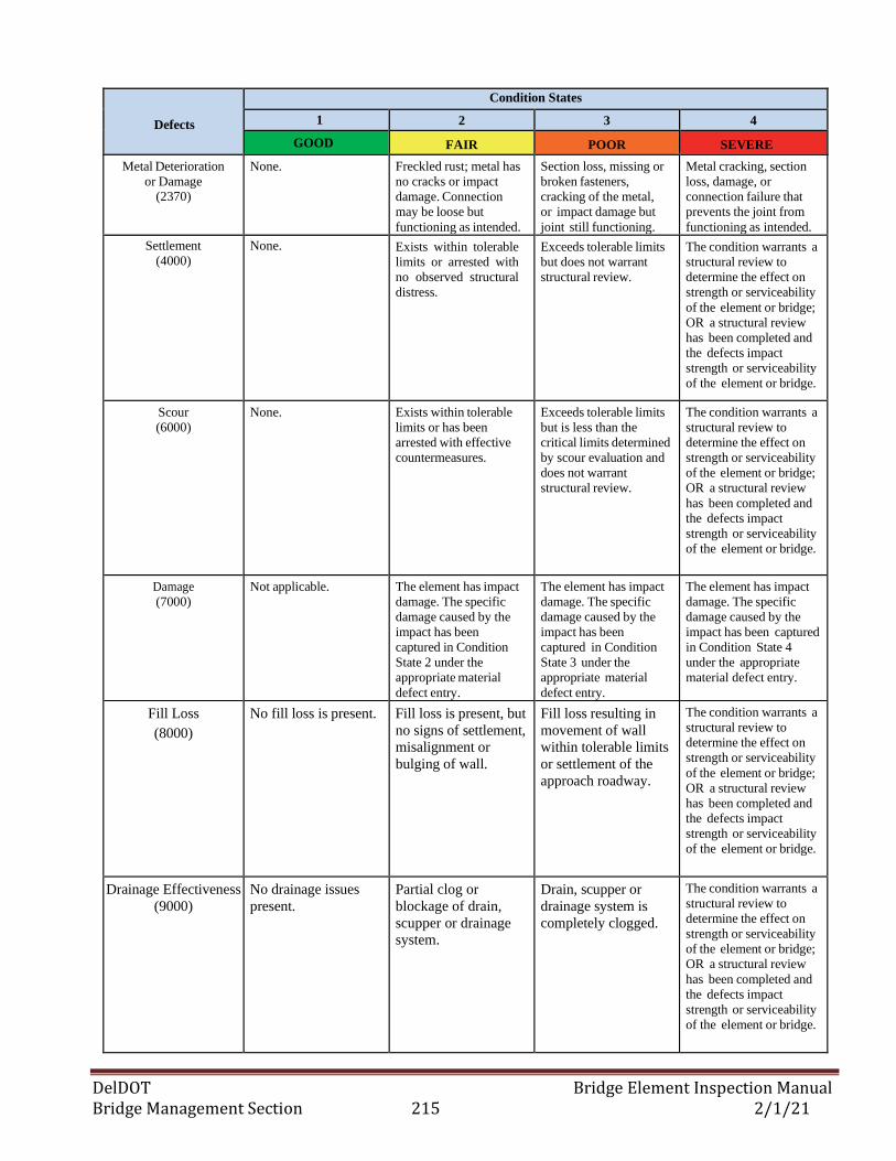
DelDOT Bridge Element Inspection Manual Bridge Management Section 215 2/1/21
Defects
Condition States
1 2 3 4
GOOD FAIR POOR SEVERE
Metal Deterioration
or Damage (2370)
None. Freckled rust; metal has
no cracks or impact
damage. Connection
may be loose but
functioning as intended.
Section loss, missing or
broken fasteners,
cracking of the metal,
or impact damage but
joint still functioning.
Metal cracking, section
loss, damage, or
connection failure that
prevents the joint from
functioning as intended.
Settlement
(4000)
None. Exists within tolerable
limits or arrested with
no observed structural
distress.
Exceeds tolerable limits
but does not warrant
structural review.
The condition warrants a
structural review to
determine the effect on
strength or serviceability
of the element or bridge;
OR a structural review
has been completed and
the defects impact
strength or serviceability
of the element or bridge.
Scour
(6000)
None. Exists within tolerable
limits or has been
arrested with effective
countermeasures.
Exceeds tolerable limits
but is less than the
critical limits determined
by scour evaluation and
does not warrant
structural review.
The condition warrants a
structural review to
determine the effect on
strength or serviceability
of the element or bridge;
OR a structural review
has been completed and
the defects impact
strength or serviceability
of the element or bridge.
Damage
(7000)
Not applicable. The element has impact
damage. The specific
damage caused by the
impact has been
captured in Condition
State 2 under the
appropriate material
defect entry.
The element has impact
damage. The specific
damage caused by the
impact has been
captured in Condition
State 3 under the
appropriate material
defect entry.
The element has impact
damage. The specific
damage caused by the
impact has been captured
in Condition State 4
under the appropriate
material defect entry.
Fill Loss
(8000)
No fill loss is present. Fill loss is present, but
no signs of settlement,
misalignment or
bulging of wall.
Fill loss resulting in
movement of wall
within tolerable limits
or settlement of the
approach roadway.
The condition warrants a
structural review to
determine the effect on
strength or serviceability
of the element or bridge;
OR a structural review
has been completed and
the defects impact
strength or serviceability
of the element or bridge.
Drainage Effectiveness
(9000)
No drainage issues
present.
Partial clog or
blockage of drain,
scupper or drainage
system.
Drain, scupper or
drainage system is
completely clogged.
The condition warrants a
structural review to
determine the effect on
strength or serviceability
of the element or bridge;
OR a structural review
has been completed and
the defects impact
strength or serviceability
of the element or bridge.
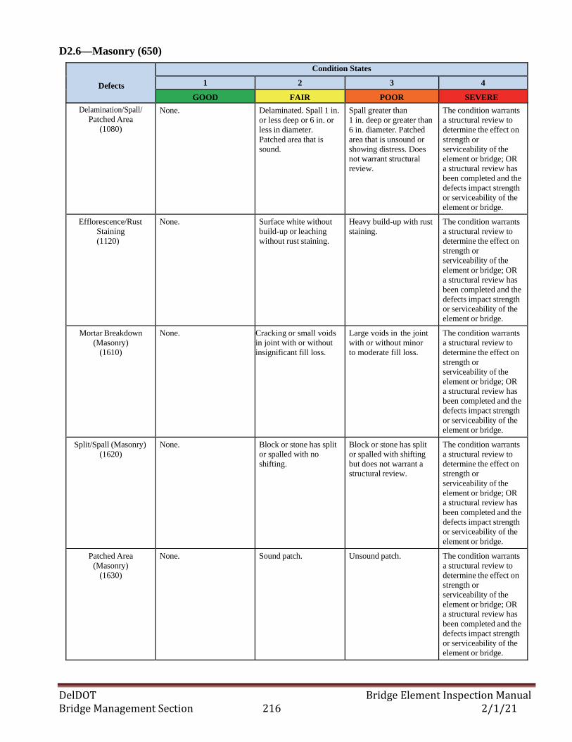
DelDOT Bridge Element Inspection Manual Bridge Management Section 216 2/1/21
D2.6—Masonry (650)
Defects
Condition States
1 2 3 4
GOOD FAIR POOR SEVERE
Delamination/Spall/
Patched Area
(1080)
None. Delaminated. Spall 1 in.
or less deep or 6 in. or
less in diameter.
Patched area that is
sound.
Spall greater than
1 in. deep or greater than
6 in. diameter. Patched
area that is unsound or
showing distress. Does
not warrant structural
review.
The condition warrants
a structural review to
determine the effect on
strength or
serviceability of the
element or bridge; OR
a structural review has
been completed and the
defects impact strength
or serviceability of the
element or bridge.
Efflorescence/Rust
Staining
(1120)
None. Surface white without
build-up or leaching
without rust staining.
Heavy build-up with rust
staining.
The condition warrants
a structural review to
determine the effect on
strength or
serviceability of the
element or bridge; OR
a structural review has
been completed and the
defects impact strength
or serviceability of the
element or bridge.
Mortar Breakdown
(Masonry) (1610)
None. Cracking or small voids
in joint with or without
insignificant fill loss.
Large voids in the joint
with or without minor
to moderate fill loss.
The condition warrants
a structural review to
determine the effect on
strength or
serviceability of the
element or bridge; OR
a structural review has
been completed and the
defects impact strength
or serviceability of the
element or bridge.
Split/Spall (Masonry)
(1620)
None. Block or stone has split
or spalled with no
shifting.
Block or stone has split
or spalled with shifting
but does not warrant a
structural review.
The condition warrants
a structural review to
determine the effect on
strength or
serviceability of the
element or bridge; OR
a structural review has
been completed and the
defects impact strength
or serviceability of the
element or bridge.
Patched Area
(Masonry)
(1630)
None. Sound patch. Unsound patch. The condition warrants
a structural review to
determine the effect on
strength or
serviceability of the
element or bridge; OR
a structural review has
been completed and the
defects impact strength
or serviceability of the
element or bridge.
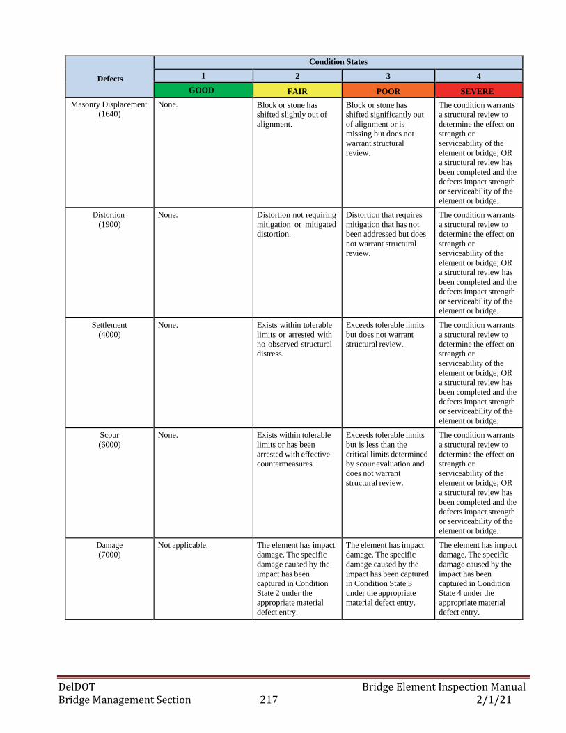
DelDOT Bridge Element Inspection Manual Bridge Management Section 217 2/1/21
Defects
Condition States
1 2 3 4
GOOD FAIR POOR SEVERE
Masonry Displacement
(1640)
None. Block or stone has
shifted slightly out of
alignment.
Block or stone has
shifted significantly out
of alignment or is
missing but does not
warrant structural
review.
The condition warrants
a structural review to
determine the effect on
strength or
serviceability of the
element or bridge; OR
a structural review has
been completed and the
defects impact strength
or serviceability of the
element or bridge.
Distortion
(1900)
None. Distortion not requiring
mitigation or mitigated
distortion.
Distortion that requires
mitigation that has not
been addressed but does
not warrant structural
review.
The condition warrants
a structural review to
determine the effect on
strength or
serviceability of the
element or bridge; OR
a structural review has
been completed and the
defects impact strength
or serviceability of the
element or bridge.
Settlement
(4000)
None. Exists within tolerable
limits or arrested with
no observed structural
distress.
Exceeds tolerable limits
but does not warrant
structural review.
The condition warrants
a structural review to
determine the effect on
strength or
serviceability of the
element or bridge; OR
a structural review has
been completed and the
defects impact strength
or serviceability of the
element or bridge.
Scour
(6000)
None. Exists within tolerable
limits or has been
arrested with effective
countermeasures.
Exceeds tolerable limits
but is less than the
critical limits determined
by scour evaluation and
does not warrant
structural review.
The condition warrants
a structural review to
determine the effect on
strength or
serviceability of the
element or bridge; OR
a structural review has
been completed and the
defects impact strength
or serviceability of the
element or bridge.
Damage
(7000)
Not applicable. The element has impact
damage. The specific
damage caused by the
impact has been
captured in Condition
State 2 under the
appropriate material
defect entry.
The element has impact
damage. The specific
damage caused by the
impact has been captured
in Condition State 3
under the appropriate
material defect entry.
The element has impact
damage. The specific
damage caused by the
impact has been
captured in Condition
State 4 under the
appropriate material
defect entry.
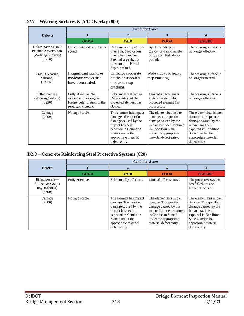
DelDOT Bridge Element Inspection Manual Bridge Management Section 218 2/1/21
D2.7—Wearing Surfaces & A/C Overlay (800)
Defects
Condition States
1 2 3 4
GOOD FAIR POOR SEVERE
Delamination/Spall/
Patched Area/Pothole
(Wearing Surfaces)
(3210)
None. Patched area that is
sound.
Delaminated. Spall less
than 1 in. deep or less
than 6 in. diameter.
Patched area that is
u n sound. Partial
depth pothole.
Spall 1 in. deep or
greater or 6 in. diameter
or greater. Full depth
pothole.
The wearing surface is
no longer effective.
Crack (Wearing
Surface)
(3220)
Insignificant cracks or
moderate cracks that
have been sealed.
Unsealed moderate
cracks or unsealed
moderate map
cracking.
Wide cracks or heavy
map cracking. The wearing surface is
no longer effective.
Effectiveness
(Wearing Surface)
(3230)
Fully effective. No
evidence of leakage or
further deterioration of the
protected element.
Substantially effective.
Deterioration of the
protected element has
slowed.
Limited effectiveness.
Deterioration of the
protected element has
progressed.
The wearing surface is
no longer effective.
Damage
(7000)
Not applicable. The element has impact
damage. The specific
damage caused by the
impact has been
captured in Condition
State 2 under the
appropriate material
defect entry.
The element has impact
damage. The specific
damage caused by the
impact has been captured
in Condition State 3
under the appropriate
material defect entry.
The element has impact
damage. The specific
damage caused by the
impact has been
captured in Condition
State 4 under the
appropriate material
defect entry.
D2.8—Concrete Reinforcing Steel Protective Systems (820)
Defects
Condition States
1 2 3 4
GOOD FAIR POOR SEVERE
Effectiveness—
Protective System
(e.g. cathodic)
(3600)
Fully effective. Substantially effective. Limited effectiveness. The protective system
has failed or is no
longer effective.
Damage
(7000)
Not applicable. The element has impact
damage. The specific
damage caused by the
impact has been
captured in Condition
State 2 under the
appropriate material
defect entry.
The element has impact
damage. The specific
damage caused by the
impact has been captured
in Condition State 3
under the appropriate
material defect entry.
The element has impact
damage. The specific
damage caused by the
impact has been
captured in Condition
State 4 under the
appropriate material
defect entry.
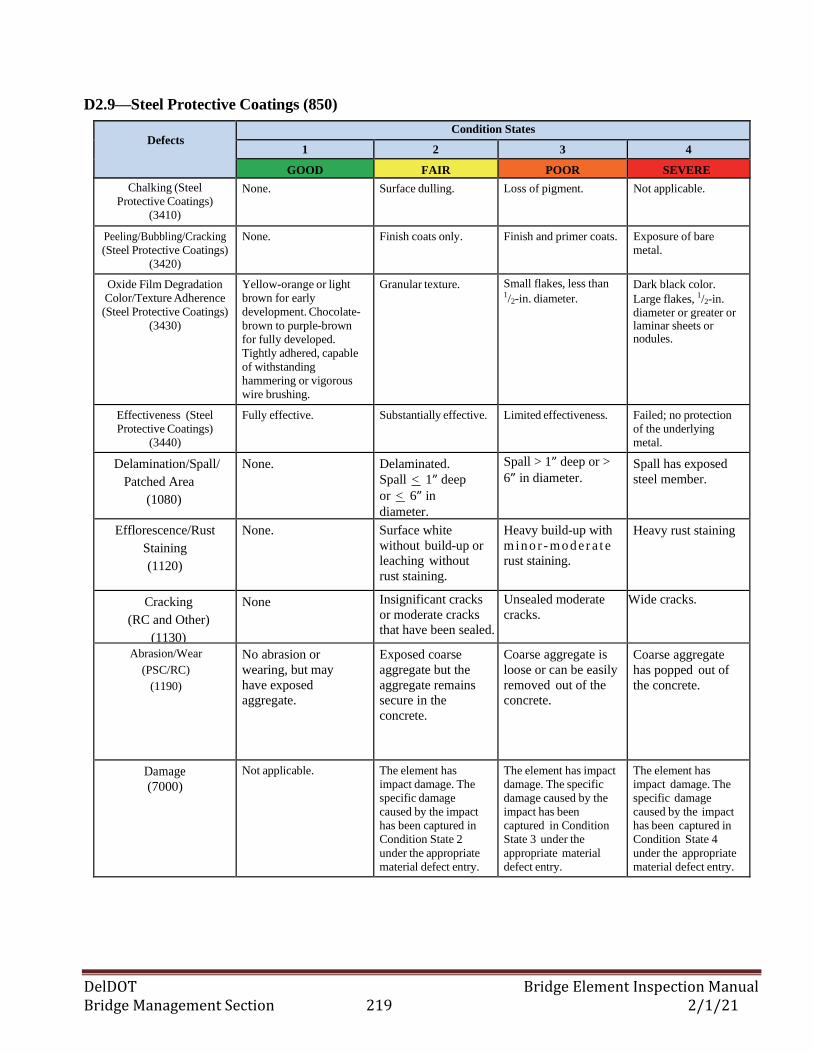
DelDOT Bridge Element Inspection Manual Bridge Management Section 219 2/1/21
D2.9—Steel Protective Coatings (850)
Defects
Condition States
1 2 3 4
GOOD FAIR POOR SEVERE
Chalking (Steel
Protective Coatings)
(3410)
None. Surface dulling. Loss of pigment. Not applicable.
Peeling/Bubbling/Cracking
(Steel Protective Coatings)
(3420)
None. Finish coats only. Finish and primer coats. Exposure of bare
metal.
Oxide Film Degradation
Color/Texture Adherence
(Steel Protective Coatings)
(3430)
Yellow-orange or light
brown for early
development. Chocolate-
brown to purple-brown
for fully developed.
Tightly adhered, capable
of withstanding
hammering or vigorous
wire brushing.
Granular texture. Small flakes, less than 1/2-in. diameter.
Dark black color.
Large flakes, 1/2-in. diameter or greater or laminar sheets or nodules.
Effectiveness (Steel
Protective Coatings)
(3440)
Fully effective. Substantially effective. Limited effectiveness. Failed; no protection
of the underlying
metal.
Delamination/Spall/
Patched Area
(1080)
None.
Delaminated.
Spall < 1” deep
or < 6” in
diameter.
Spall > 1” deep or >
6” in diameter. Spall has exposed
steel member.
Efflorescence/Rust
Staining
(1120)
None. Surface white
without build-up or
leaching without
rust staining.
Heavy build-up with
min o r - mo d er a t e
rust staining.
Heavy rust staining
Cracking
(RC and Other)
(1130)
None Insignificant cracks
or moderate cracks
that have been sealed.
Unsealed moderate
cracks.
Wide cracks.
Abrasion/Wear
(PSC/RC)
(1190)
No abrasion or
wearing, but may
have exposed
aggregate.
Exposed coarse
aggregate but the
aggregate remains
secure in the
concrete.
Coarse aggregate is
loose or can be easily
removed out of the
concrete.
Coarse aggregate
has popped out of
the concrete.
Damage
(7000)
Not applicable. The element has
impact damage. The
specific damage
caused by the impact
has been captured in
Condition State 2
under the appropriate
material defect entry.
The element has impact
damage. The specific
damage caused by the
impact has been
captured in Condition
State 3 under the
appropriate material
defect entry.
The element has
impact damage. The
specific damage
caused by the impact
has been captured in
Condition State 4
under the appropriate
material defect entry.
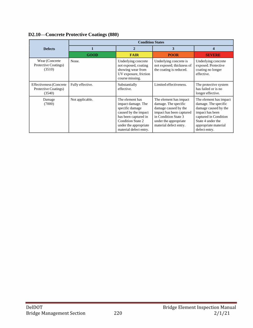
DelDOT Bridge Element Inspection Manual Bridge Management Section 220 2/1/21
D2.10—Concrete Protective Coatings (880)
Defects
Condition States
1 2 3 4
GOOD FAIR POOR SEVERE
Wear (Concrete
Protective Coatings)
(3510)
None. Underlying concrete
not exposed, coating
showing wear from
UV exposure, friction
course missing.
Underlying concrete is
not exposed; thickness of
the coating is reduced.
Underlying concrete
exposed. Protective
coating no longer
effective.
Effectiveness (Concrete
Protective Coatings)
(3540)
Fully effective. Substantially
effective.
Limited effectiveness. The protective system
has failed or is no
longer effective.
Damage
(7000)
Not applicable. The element has
impact damage. The
specific damage
caused by the impact
has been captured in
Condition State 2
under the appropriate
material defect entry.
The element has impact
damage. The specific
damage caused by the
impact has been captured
in Condition State 3
under the appropriate
material defect entry.
The element has impact
damage. The specific
damage caused by the
impact has been
captured in Condition
State 4 under the
appropriate material
defect entry.
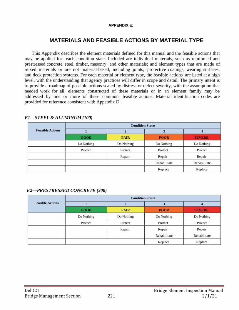
DelDOT Bridge Element Inspection Manual Bridge Management Section 221 2/1/21
APPENDIX E:
MATERIALS AND FEASIBLE ACTIONS BY MATERIAL TYPE
This Appendix describes the element materials defined for this manual and the feasible actions that
may be applied for each condition state. Included are individual materials, such as reinforced and
prestressed concrete, steel, timber, masonry, and other materials; and element types that are made of
mixed materials or are not material-based, including joints, protective coatings, wearing surfaces,
and deck protection systems. For each material or element type, the feasible actions are listed at a high
level, with the understanding that agency practices will differ in scope and detail. The primary intent is
to provide a roadmap of possible actions scaled by distress or defect severity, with the assumption that
needed work for all elements constructed of these materials or in an element family may be
addressed by one or more of these common feasible actions. Material identification codes are
provided for reference consistent with Appendix D.
E1—STEEL & ALUMINUM (100)
Feasible Actions
Condition States
1 2 3 4
GOOD FAIR POOR SEVERE
Do Nothing Do Nothing Do Nothing Do Nothing
Protect Protect Protect Protect
Repair Repair Repair
Rehabilitate Rehabilitate
Replace Replace
E2—PRESTRESSED CONCRETE (300)
Feasible Actions
Condition States
1 2 3 4
GOOD FAIR POOR SEVERE
Do Nothing Do Nothing Do Nothing Do Nothing
Protect Protect Protect Protect
Repair Repair Repair
Rehabilitate Rehabilitate
Replace Replace
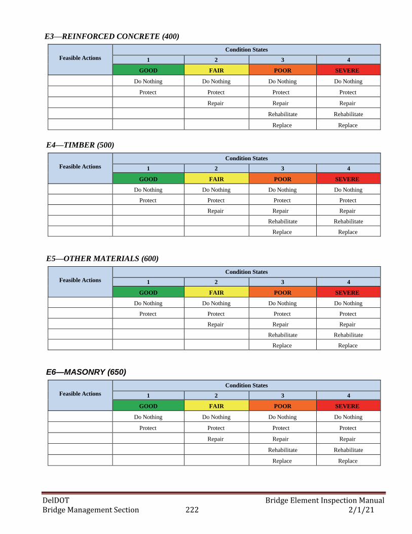
DelDOT Bridge Element Inspection Manual Bridge Management Section 222 2/1/21
E3—REINFORCED CONCRETE (400)
Feasible Actions
Condition States
1 2 3 4
GOOD FAIR POOR SEVERE
Do Nothing Do Nothing Do Nothing Do Nothing
Protect Protect Protect Protect
Repair Repair Repair
Rehabilitate Rehabilitate
Replace Replace
E4—TIMBER (500)
Feasible Actions
Condition States
1 2 3 4
GOOD FAIR POOR SEVERE
Do Nothing Do Nothing Do Nothing Do Nothing
Protect Protect Protect Protect
Repair Repair Repair
Rehabilitate Rehabilitate
Replace Replace
E5—OTHER MATERIALS (600)
Feasible Actions
Condition States
1 2 3 4
GOOD FAIR POOR SEVERE
Do Nothing Do Nothing Do Nothing Do Nothing
Protect Protect Protect Protect
Repair Repair Repair
Rehabilitate Rehabilitate
Replace Replace
E6—MASONRY (650)
Feasible Actions
Condition States
1 2 3 4
GOOD FAIR POOR SEVERE
Do Nothing Do Nothing Do Nothing Do Nothing
Protect Protect Protect Protect
Repair Repair Repair
Rehabilitate Rehabilitate
Replace Replace
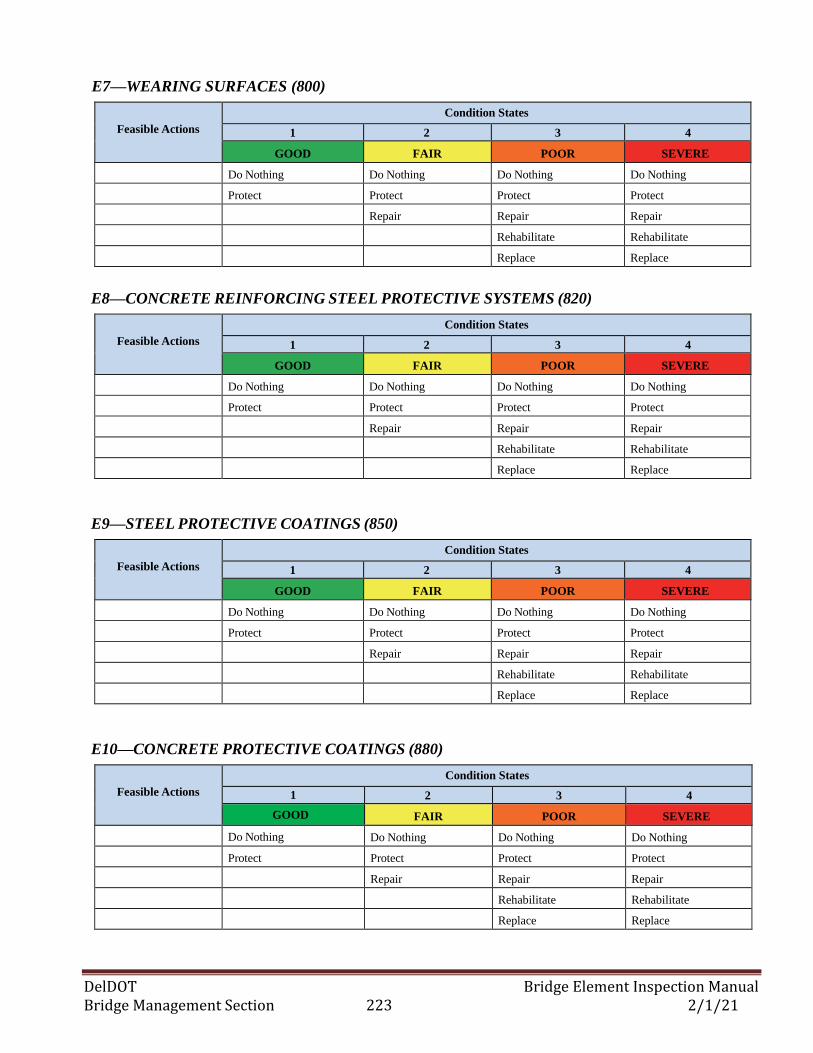
DelDOT Bridge Element Inspection Manual Bridge Management Section 223 2/1/21
E7—WEARING SURFACES (800)
Feasible Actions
Condition States
1 2 3 4
GOOD FAIR POOR SEVERE
Do Nothing Do Nothing Do Nothing Do Nothing
Protect Protect Protect Protect
Repair Repair Repair
Rehabilitate Rehabilitate
Replace Replace
E8—CONCRETE REINFORCING STEEL PROTECTIVE SYSTEMS (820)
Feasible Actions
Condition States
1 2 3 4
GOOD FAIR POOR SEVERE
Do Nothing Do Nothing Do Nothing Do Nothing
Protect Protect Protect Protect
Repair Repair Repair
Rehabilitate Rehabilitate
Replace Replace
E9—STEEL PROTECTIVE COATINGS (850)
Feasible Actions
Condition States
1 2 3 4
GOOD FAIR POOR SEVERE
Do Nothing Do Nothing Do Nothing Do Nothing
Protect Protect Protect Protect
Repair Repair Repair
Rehabilitate Rehabilitate
Replace Replace
E10—CONCRETE PROTECTIVE COATINGS (880)
Feasible Actions
Condition States
1 2 3 4
GOOD FAIR POOR SEVERE
Do Nothing Do Nothing Do Nothing Do Nothing
Protect Protect Protect Protect
Repair Repair Repair
Rehabilitate Rehabilitate
Replace Replace
DelDOT Bridge Element Inspection Manual Bridge Management Section 224 2/1/21
DelDOT Bridge Element Inspection Manual Bridge Management Section 225 2/1/21
APPENDIX F:
MAXIMO MAINTENANCE REQUESTS
For each bridge inspected the following maintenance items shall be requested by the bridge
inspector where applicable. The maintenance shall be entered into Maximo with the appropriate
priority.
F1—MAXIMO PRIORITY 3 MAINTENANCE
Removal of vegetation and debris when affecting the bridge. Special attention shall be given
to areas around MSE walls and concrete slope paving as these areas are more susceptible to
damage from vegetation. See NBI Item #61. (BMS code B055-V1A) (Function code
11105.5)
Repair of erosion and placement of erosion control measures when the bridge is affected (CS2
or worse). (Element #829 ) (BMS code B054-S6D) (Function Code 11105.4)
Repair of open grid deck, repairing broken connections or replacing damaged areas. (BMS
code B024-P1A) (Function code 11102.4)
Re-seal pourable deck joints, Element #301 (BMS code B007-S1H) (Function code 11100.7).
Special attention should be given to the joint between the approach slab and wingwalls/parapet
or other area where erosion and undermining potential exists. If it is apparent that MOT
would be excessive do not re-seal the joint in the travel lanes.
Clean & paint deteriorated primary load carrying steel members (CS4– Steel). Typically, this
work will be localized to a specific area or location. (BMS code B005-S2K) (Maximo
Function Code 11100.5)
F2—MAXIMO PRIORITY 2 MAINTENANCE
Repair of deck, slab, and approach slab spalls. (Condition State 2 and top surfaces only) (BMS
code B025-P1A or B022-S1D) (Function Code 11102.5)
Repair of header spalls. (BMS code B041-S3B) (Function code 11104.1)
Repair of AC overlay, Element #801 or 811, (CS 2 only) or repair of hot mix (any condition state)
over; culvert, slab under fill, filled arch or approach slab, (BMS code B022-S1D) (Function code
11102.2) or hot mix wedge placement to account for settlement at the ends of bridges.
Clean out scuppers and/or drains (BMS code B002-S1G) (Function Code 11100.2)
F3—MAXIMO PRIORITY 1 MAINTENANCE
Cleaning/clearing weepholes in P.S. conc. box beams. (Function code 11107.1)
Clean/flush bearings/bearing seat (use when debris may cause deterioration of bearing or
bearing seat) (BMS code B003-S2J) (Function code 11100.3)
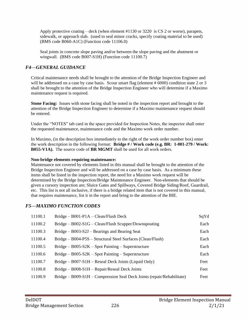
DelDOT Bridge Element Inspection Manual Bridge Management Section 226 2/1/21
Apply protective coating – deck (when element #1130 or 3220 is CS 2 or worse), parapets,
sidewalk, or approach slab. (used to seal minor cracks, specify coating material to be used)
(BMS code B060-A1C) (Function code 11106.0)
Seal joints in concrete slope paving and/or between the slope paving and the abutment or
wingwall. (BMS code B007-S1H) (Function code 11100.7)
F4—GENERAL GUIDANCE
Critical maintenance needs shall be brought to the attention of the Bridge Inspection Engineer and
will be addressed on a case by case basis. Scour smart flag (element # 6000) condition state 2 or 3
shall be brought to the attention of the Bridge Inspection Engineer who will determine if a Maximo
maintenance request is required.
Stone Facing: Issues with stone facing shall be noted in the inspection report and brought to the
attention of the Bridge Inspection Engineer to determine if a Maximo maintenance request should
be entered.
Under the “NOTES” tab card in the space provided for Inspection Notes, the inspector shall enter
the requested maintenance, maintenance code and the Maximo work order number.
In Maximo, (in the description box immediately to the right of the work order number box) enter
the work description in the following format: Bridge # / Work code (e.g. BR: 1-001-279 / Work:
B055-V1A). The source code of BR MGMT shall be used for all work orders.
Non-bridge elements requiring maintenance:
Maintenance not covered by elements listed in this manual shall be brought to the attention of the
Bridge Inspection Engineer and will be addressed on a case by case basis. As a minimum these
items shall be listed in the inspection report, the need for a Maximo work request will be
determined by the Bridge Inspection/Bridge Maintenance Engineer. Non-elements that should be
given a cursory inspection are; Sluice Gates and Spillways, Covered Bridge Siding/Roof, Guardrail,
etc. This list is not all inclusive, if there is a bridge related item that is not covered in this manual,
that requires maintenance, list it in the report and bring to the attention of the BIE.
F5—MAXIMO FUNCTION CODES
11100.1 Bridge – B001-P1A – Clean/Flush Deck SqYd
11100.2 Bridge – B002-S1G – Clean/Flush Scupper/Downspouting Each
11100.3 Bridge – B003-S2J – Bearings and Bearing Seat Each
11100.4 Bridge – B004-P5S – Structural Steel Surfaces (Clean/Flush) Each
11100.5 Bridge – B005-S2K – Spot Painting – Superstructure Each
11100.6 Bridge – B005-S2K – Spot Painting – Superstructure Each
11100.7 Bridge – B007-S1H – Reseal Deck Joints (Liquid Only) Feet
11100.8 Bridge – B008-S1H – Repair/Reseal Deck Joints Feet
11100.9 Bridge – B009-S1H – Compression Seal Deck Joints (repair/Rehabilitate) Feet
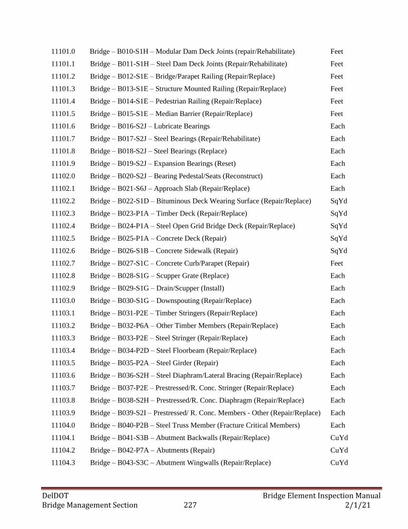
DelDOT Bridge Element Inspection Manual Bridge Management Section 227 2/1/21
11101.0 Bridge – B010-S1H – Modular Dam Deck Joints (repair/Rehabilitate) Feet
11101.1 Bridge – B011-S1H – Steel Dam Deck Joints (Repair/Rehabilitate) Feet
11101.2 Bridge – B012-S1E – Bridge/Parapet Railing (Repair/Replace) Feet
11101.3 Bridge – B013-S1E – Structure Mounted Railing (Repair/Replace) Feet
11101.4 Bridge – B014-S1E – Pedestrian Railing (Repair/Replace) Feet
11101.5 Bridge – B015-S1E – Median Barrier (Repair/Replace) Feet
11101.6 Bridge – B016-S2J – Lubricate Bearings Each
11101.7 Bridge – B017-S2J – Steel Bearings (Repair/Rehabilitate) Each
11101.8 Bridge – B018-S2J – Steel Bearings (Replace) Each
11101.9 Bridge – B019-S2J – Expansion Bearings (Reset) Each
11102.0 Bridge – B020-S2J – Bearing Pedestal/Seats (Reconstruct) Each
11102.1 Bridge – B021-S6J – Approach Slab (Repair/Replace) Each
11102.2 Bridge – B022-S1D – Bituminous Deck Wearing Surface (Repair/Replace) SqYd
11102.3 Bridge – B023-P1A – Timber Deck (Repair/Replace) SqYd
11102.4 Bridge – B024-P1A – Steel Open Grid Bridge Deck (Repair/Replace) SqYd
11102.5 Bridge – B025-P1A – Concrete Deck (Repair) SqYd
11102.6 Bridge – B026-S1B – Concrete Sidewalk (Repair) SqYd
11102.7 Bridge – B027-S1C – Concrete Curb/Parapet (Repair) Feet
11102.8 Bridge – B028-S1G – Scupper Grate (Replace) Each
11102.9 Bridge – B029-S1G – Drain/Scupper (Install) Each
11103.0 Bridge – B030-S1G – Downspouting (Repair/Replace) Each
11103.1 Bridge – B031-P2E – Timber Stringers (Repair/Replace) Each
11103.2 Bridge – B032-P6A – Other Timber Members (Repair/Replace) Each
11103.3 Bridge – B033-P2E – Steel Stringer (Repair/Replace) Each
11103.4 Bridge – B034-P2D – Steel Floorbeam (Repair/Replace) Each
11103.5 Bridge – B035-P2A – Steel Girder (Repair) Each
11103.6 Bridge – B036-S2H – Steel Diaphram/Lateral Bracing (Repair/Replace) Each
11103.7 Bridge – B037-P2E – Prestressed/R. Conc. Stringer (Repair/Replace) Each
11103.8 Bridge – B038-S2H – Prestressed/R. Conc. Diaphragm (Repair/Replace) Each
11103.9 Bridge – B039-S2I – Prestressed/ R. Conc. Members - Other (Repair/Replace) Each
11104.0 Bridge – B040-P2B – Steel Truss Member (Fracture Critical Members) Each
11104.1 Bridge – B041-S3B – Abutment Backwalls (Repair/Replace) CuYd
11104.2 Bridge – B042-P7A – Abutments (Repair) CuYd
11104.3 Bridge – B043-S3C – Abutment Wingwalls (Repair/Replace) CuYd
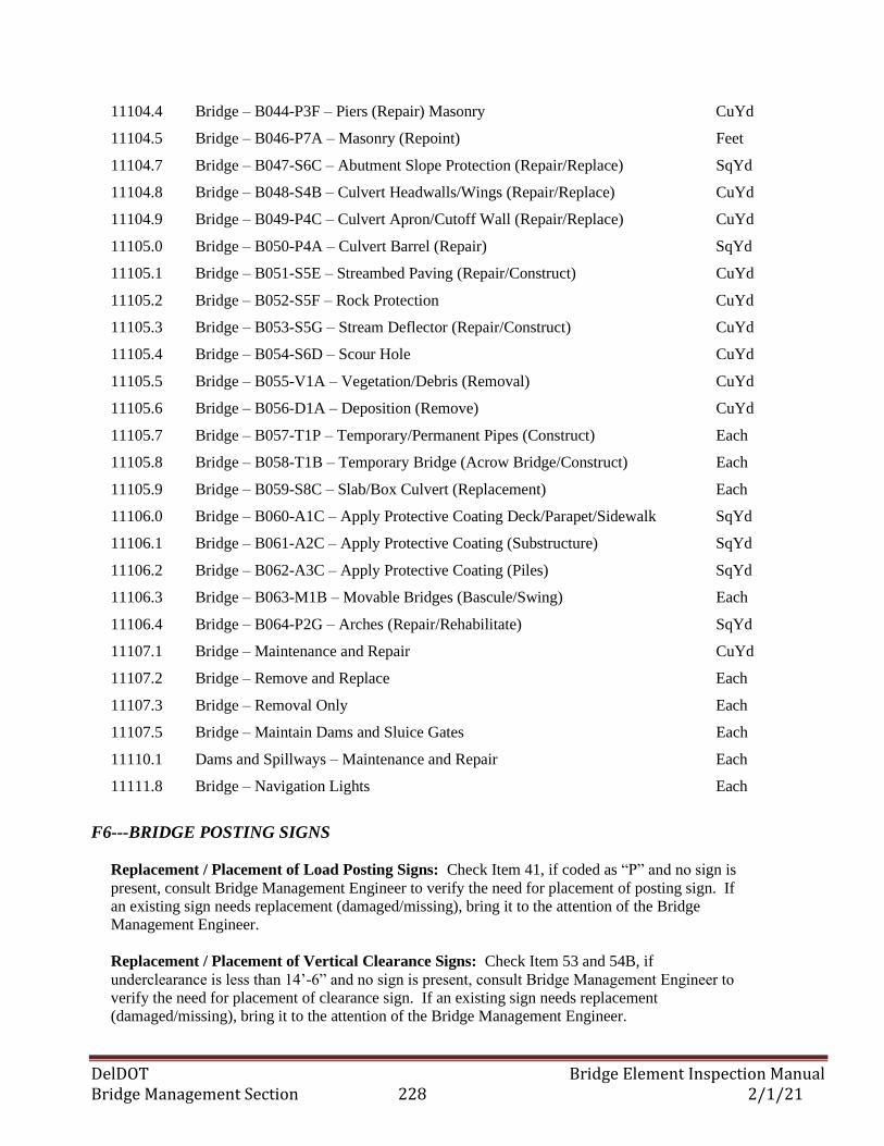
DelDOT Bridge Element Inspection Manual Bridge Management Section 228 2/1/21
11104.4 Bridge – B044-P3F – Piers (Repair) Masonry CuYd
11104.5 Bridge – B046-P7A – Masonry (Repoint) Feet
11104.7 Bridge – B047-S6C – Abutment Slope Protection (Repair/Replace) SqYd
11104.8 Bridge – B048-S4B – Culvert Headwalls/Wings (Repair/Replace) CuYd
11104.9 Bridge – B049-P4C – Culvert Apron/Cutoff Wall (Repair/Replace) CuYd
11105.0 Bridge – B050-P4A – Culvert Barrel (Repair) SqYd
11105.1 Bridge – B051-S5E – Streambed Paving (Repair/Construct) CuYd
11105.2 Bridge – B052-S5F – Rock Protection CuYd
11105.3 Bridge – B053-S5G – Stream Deflector (Repair/Construct) CuYd
11105.4 Bridge – B054-S6D – Scour Hole CuYd
11105.5 Bridge – B055-V1A – Vegetation/Debris (Removal) CuYd
11105.6 Bridge – B056-D1A – Deposition (Remove) CuYd
11105.7 Bridge – B057-T1P – Temporary/Permanent Pipes (Construct) Each
11105.8 Bridge – B058-T1B – Temporary Bridge (Acrow Bridge/Construct) Each
11105.9 Bridge – B059-S8C – Slab/Box Culvert (Replacement) Each
11106.0 Bridge – B060-A1C – Apply Protective Coating Deck/Parapet/Sidewalk SqYd
11106.1 Bridge – B061-A2C – Apply Protective Coating (Substructure) SqYd
11106.2 Bridge – B062-A3C – Apply Protective Coating (Piles) SqYd
11106.3 Bridge – B063-M1B – Movable Bridges (Bascule/Swing) Each
11106.4 Bridge – B064-P2G – Arches (Repair/Rehabilitate) SqYd
11107.1 Bridge – Maintenance and Repair CuYd
11107.2 Bridge – Remove and Replace Each
11107.3 Bridge – Removal Only Each
11107.5 Bridge – Maintain Dams and Sluice Gates Each
11110.1 Dams and Spillways – Maintenance and Repair Each
11111.8 Bridge – Navigation Lights Each
F6---BRIDGE POSTING SIGNS
Replacement / Placement of Load Posting Signs: Check Item 41, if coded as “P” and no sign is
present, consult Bridge Management Engineer to verify the need for placement of posting sign. If
an existing sign needs replacement (damaged/missing), bring it to the attention of the Bridge
Management Engineer.
Replacement / Placement of Vertical Clearance Signs: Check Item 53 and 54B, if
underclearance is less than 14’-6” and no sign is present, consult Bridge Management Engineer to
verify the need for placement of clearance sign. If an existing sign needs replacement
(damaged/missing), bring it to the attention of the Bridge Management Engineer.
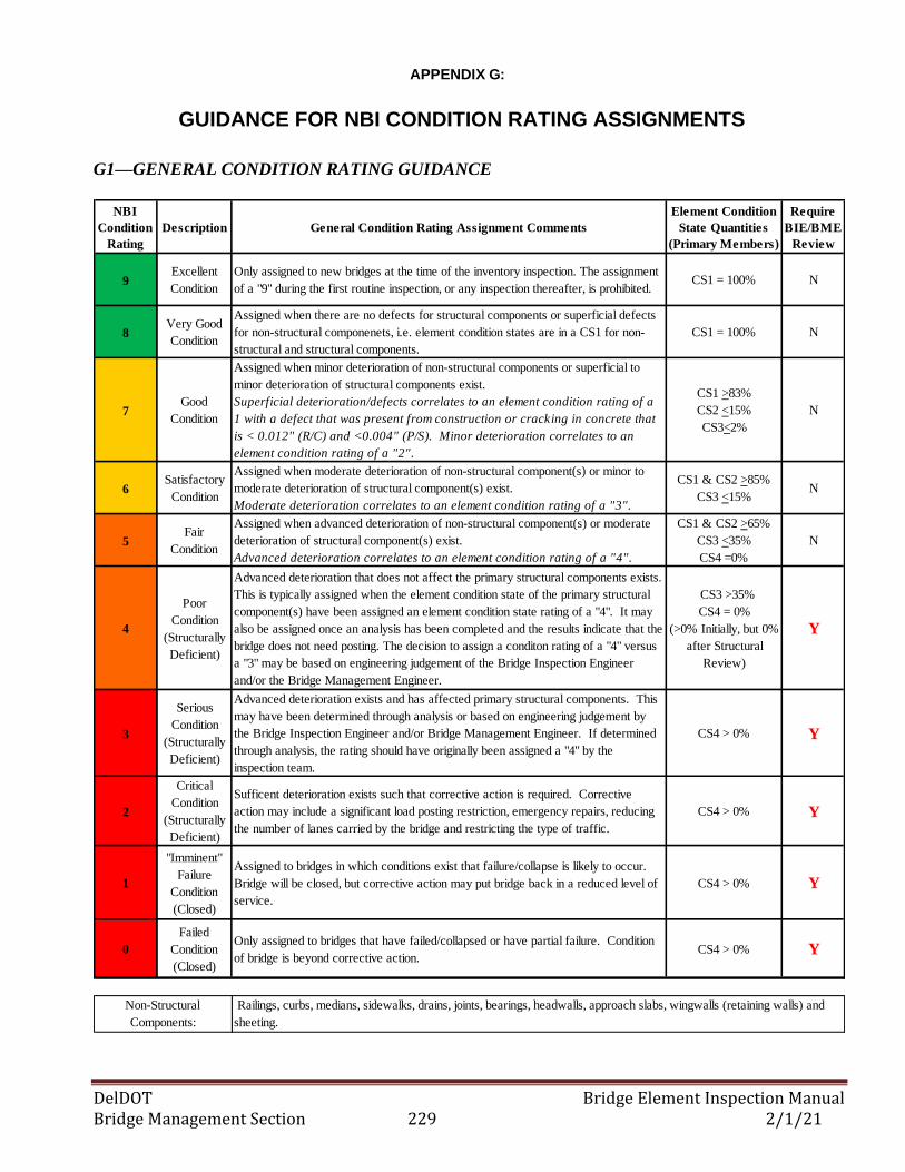
DelDOT Bridge Element Inspection Manual Bridge Management Section 229 2/1/21
APPENDIX G:
GUIDANCE FOR NBI CONDITION RATING ASSIGNMENTS
G1—GENERAL CONDITION RATING GUIDANCE
NBI
Condition
Rating
Description General Condition Rating Assignment Comments
Element Condition
State Quantities
(Primary Members)
Require
BIE/BME
Review
9Excellent
Condition
Only assigned to new bridges at the time of the inventory inspection. The assignment
of a "9" during the first routine inspection, or any inspection thereafter, is prohibited. CS1 = 100% N
8Very Good
Condition
Assigned when there are no defects for structural components or superficial defects
for non-structural componenets, i.e. element condition states are in a CS1 for non-
structural and structural components.
CS1 = 100% N
7Good
Condition
Assigned when minor deterioration of non-structural components or superficial to
minor deterioration of structural components exist.
Superficial deterioration/defects correlates to an element condition rating of a
1 with a defect that was present from construction or cracking in concrete that
is < 0.012" (R/C) and <0.004" (P/S). Minor deterioration correlates to an
element condition rating of a "2".
CS1 >83%
CS2 <15%
CS3<2%
N
6Satisfactory
Condition
Assigned when moderate deterioration of non-structural component(s) or minor to
moderate deterioration of structural component(s) exist.
Moderate deterioration correlates to an element condition rating of a "3".
CS1 & CS2 >85%
CS3 <15% N
5Fair
Condition
Assigned when advanced deterioration of non-structural component(s) or moderate
deterioration of structural component(s) exist.
Advanced deterioration correlates to an element condition rating of a "4".
CS1 & CS2 >65%
CS3 <35%
CS4 =0%
N
4
Poor
Condition
(Structurally
Deficient)
Advanced deterioration that does not affect the primary structural components exists.
This is typically assigned when the element condition state of the primary structural
component(s) have been assigned an element condition state rating of a "4". It may
also be assigned once an analysis has been completed and the results indicate that the
bridge does not need posting. The decision to assign a conditon rating of a "4" versus
a "3" may be based on engineering judgement of the Bridge Inspection Engineer
and/or the Bridge Management Engineer.
CS3 >35%
CS4 = 0%
(>0% Initially, but 0%
after Structural
Review)
Y
3
Serious
Condition
(Structurally
Deficient)
Advanced deterioration exists and has affected primary structural components. This
may have been determined through analysis or based on engineering judgement by
the Bridge Inspection Engineer and/or Bridge Management Engineer. If determined
through analysis, the rating should have originally been assigned a "4" by the
inspection team.
CS4 > 0% Y
2
Critical
Condition
(Structurally
Deficient)
Sufficent deterioration exists such that corrective action is required. Corrective
action may include a significant load posting restriction, emergency repairs, reducing
the number of lanes carried by the bridge and restricting the type of traffic.
CS4 > 0% Y
1
"Imminent"
Failure
Condition
(Closed)
Assigned to bridges in which conditions exist that failure/collapse is likely to occur.
Bridge will be closed, but corrective action may put bridge back in a reduced level of
service.
CS4 > 0% Y
0
Failed
Condition
(Closed)
Only assigned to bridges that have failed/collapsed or have partial failure. Condition
of bridge is beyond corrective action.CS4 > 0% Y
Non-Structural
Components:
Railings, curbs, medians, sidewalks, drains, joints, bearings, headwalls, approach slabs, wingwalls (retaining walls) and
sheeting.
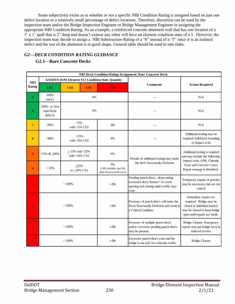
DelDOT Bridge Element Inspection Manual Bridge Management Section 230 2/1/21
Some subjectivity exists as to whether or not a specific NBI Condition Rating is assigned based on just one
defect location or a relatively small percentage of defect locations. Therefore, discretion can be used by the
inspection team and/or the Bridge Inspection Engineer or Bridge Management Engineer in assigning the
appropriate NBI Condition Rating. As an example, a reinforced concrete abutment wall that has one location of a
3’ x 1’ spall that is 2” deep and doesn’t expose any rebar will have an element condition state of a 3. However, the
inspection team may decide to assign a NBI Substructure Rating of a “6” instead of a “5” since it is an isolated
defect and the rest of the abutment is in good shape. General table should be used to rate slabs.
G2—DECK CONDITION RATING GUIDANCE
G2.1—Bare Concrete Decks
CS1 CS2 CS3 CS4
9100%
(new) --- N/A
8
100% w/ few
superficial
defects
--- N/A
7 >95% 0% --- N/A
6 >90% 0% ---
Additional testing may be
required: Full-Deck Sounding
or Impact echo
5 >75% & <90% 0%
4 < 25%0%
(>0% Initially, but 0%
after Structural Review)
3 > 0%
Pending punch-thru's , deep rutting,
excessive deck "bounce" or crack
opening and closing under traffic may
exist.
Temporary repairs or patches
may be necessary, but are not
critical.
2 > 0%
Presence of punch-thru's will make the
Deck Structurally Deficient and result in
a Critical Condition.
Immediate repairs are
required. Bridge may be
closed or individual lane(s)
may be closed to keep bridge
open until repairs are made.
1 > 0%
Presence of multiple punch-thru's
and/or excessive pending punch-thru's
may be present.
Bridge Closure. Emergency
repairs may put bridge back in
reduced service
0 > 0%Excessive punch-thru's exist and the
bridge is not safe for vehicular traffic.Bridge Closure
<5%
with <1% CS3
AASHTO BrM Element #12 Condition State Quantity
< 100%
Results of additional testing may make
the deck Structurally Deficient
NBI Deck Condition Rating Assignment: Bare Concrete Deck
0%
0%
<15%
with <5% CS3
Action RequiredCommentsNBI
Rating
Additional testing is required
and may include the following:
Impact echo, GPR, Chloride
Tests and Concrete Cores.
Repair strategy is identified..
< 100%
< 100%
< 100%
> 15% and <25%
with <10% CS3
>25%
or >10% CS3
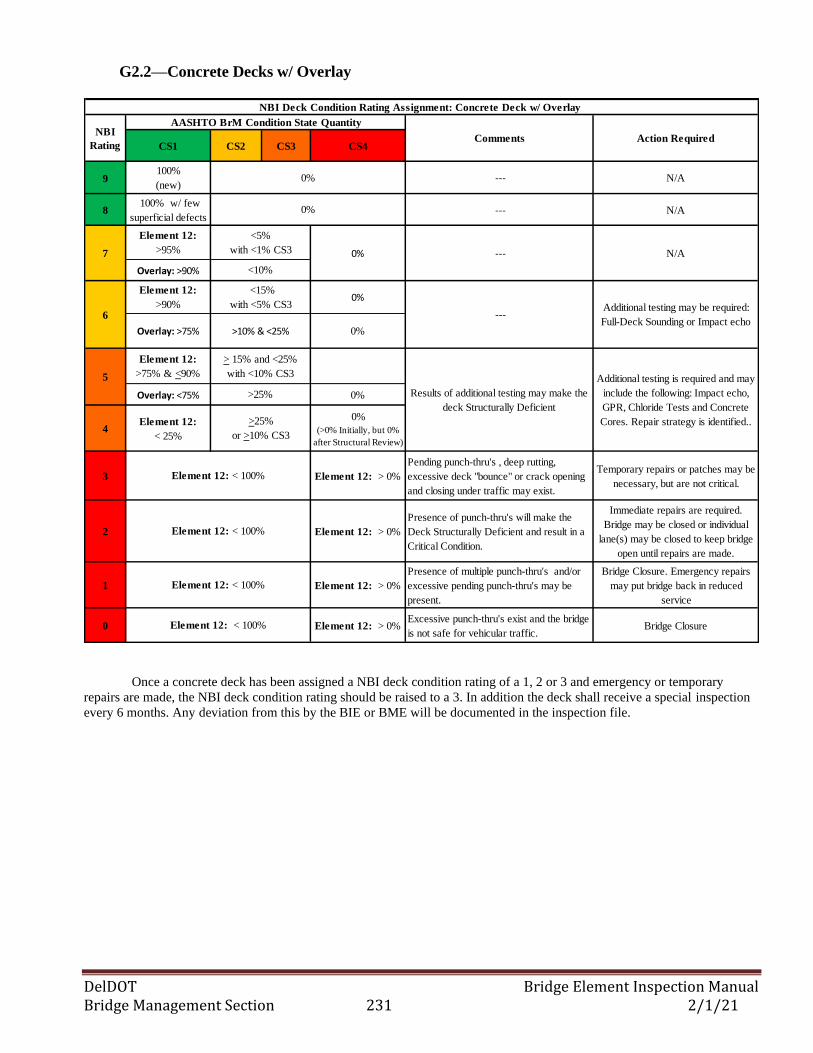
DelDOT Bridge Element Inspection Manual Bridge Management Section 231 2/1/21
G2.2—Concrete Decks w/ Overlay
CS1 CS2 CS3 CS4
9100%
(new) --- N/A
8 100% w/ few
superficial defects --- N/A
Element 12:
>95%
Overlay: >90%
Element 12:
>90% 0%
Overlay: >75% 0%
Element 12:
>75% & <90%
Overlay: <75% 0%
4Element 12:
< 25%
0%
(>0% Initially, but 0%
after Structural Review)
3 Element 12: > 0%
Pending punch-thru's , deep rutting,
excessive deck "bounce" or crack opening
and closing under traffic may exist.
Temporary repairs or patches may be
necessary, but are not critical.
2 Element 12: > 0%
Presence of punch-thru's will make the
Deck Structurally Deficient and result in a
Critical Condition.
Immediate repairs are required.
Bridge may be closed or individual
lane(s) may be closed to keep bridge
open until repairs are made.
1 Element 12: > 0%
Presence of multiple punch-thru's and/or
excessive pending punch-thru's may be
present.
Bridge Closure. Emergency repairs
may put bridge back in reduced
service
0 Element 12: > 0% Excessive punch-thru's exist and the bridge
is not safe for vehicular traffic.Bridge Closure
NBI Deck Condition Rating Assignment: Concrete Deck w/ Overlay
NBI
Rating
AASHTO BrM Condition State Quantity
Comments Action Required
7 N/A
6
5
Additional testing may be required:
Full-Deck Sounding or Impact echo ---
Additional testing is required and may
include the following: Impact echo,
GPR, Chloride Tests and Concrete
Cores. Repair strategy is identified..
Results of additional testing may make the
deck Structurally Deficient
---
<10%
>10% & <25%
> 15% and <25%
with <10% CS3
<5%
with <1% CS3
Element 12: < 100%
Element 12: < 100%
Element 12: < 100%
0%
0%
<15%
with <5% CS3
>25%
>25%
or >10% CS3
Element 12: < 100%
0%
Once a concrete deck has been assigned a NBI deck condition rating of a 1, 2 or 3 and emergency or temporary
repairs are made, the NBI deck condition rating should be raised to a 3. In addition the deck shall receive a special inspection
every 6 months. Any deviation from this by the BIE or BME will be documented in the inspection file.
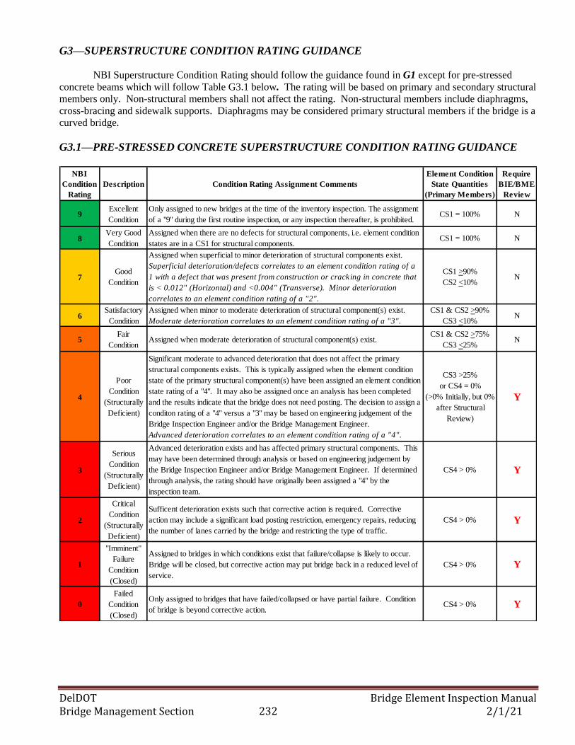
DelDOT Bridge Element Inspection Manual Bridge Management Section 232 2/1/21
G3—SUPERSTRUCTURE CONDITION RATING GUIDANCE
NBI Superstructure Condition Rating should follow the guidance found in G1 except for pre-stressed
concrete beams which will follow Table G3.1 below. The rating will be based on primary and secondary structural
members only. Non-structural members shall not affect the rating. Non-structural members include diaphragms,
cross-bracing and sidewalk supports. Diaphragms may be considered primary structural members if the bridge is a
curved bridge.
G3.1—PRE-STRESSED CONCRETE SUPERSTRUCTURE CONDITION RATING GUIDANCE
NBI
Condition
Rating
Description Condition Rating Assignment Comments
Element Condition
State Quantities
(Primary Members)
Require
BIE/BME
Review
9Excellent
Condition
Only assigned to new bridges at the time of the inventory inspection. The assignment
of a "9" during the first routine inspection, or any inspection thereafter, is prohibited. CS1 = 100% N
8Very Good
Condition
Assigned when there are no defects for structural components, i.e. element condition
states are in a CS1 for structural components.CS1 = 100% N
7Good
Condition
Assigned when superficial to minor deterioration of structural components exist.
Superficial deterioration/defects correlates to an element condition rating of a
1 with a defect that was present from construction or cracking in concrete that
is < 0.012" (Horizontal) and <0.004" (Transverse). Minor deterioration
correlates to an element condition rating of a "2".
CS1 >90%
CS2 <10%N
6Satisfactory
Condition
Assigned when minor to moderate deterioration of structural component(s) exist.
Moderate deterioration correlates to an element condition rating of a "3".
CS1 & CS2 >90%
CS3 <10%N
5Fair
ConditionAssigned when moderate deterioration of structural component(s) exist.
CS1 & CS2 >75%
CS3 <25% N
4
Poor
Condition
(Structurally
Deficient)
Significant moderate to advanced deterioration that does not affect the primary
structural components exists. This is typically assigned when the element condition
state of the primary structural component(s) have been assigned an element condition
state rating of a "4". It may also be assigned once an analysis has been completed
and the results indicate that the bridge does not need posting. The decision to assign a
conditon rating of a "4" versus a "3" may be based on engineering judgement of the
Bridge Inspection Engineer and/or the Bridge Management Engineer.
Advanced deterioration correlates to an element condition rating of a "4".
CS3 >25%
or CS4 = 0%
(>0% Initially, but 0%
after Structural
Review)
Y
3
Serious
Condition
(Structurally
Deficient)
Advanced deterioration exists and has affected primary structural components. This
may have been determined through analysis or based on engineering judgement by
the Bridge Inspection Engineer and/or Bridge Management Engineer. If determined
through analysis, the rating should have originally been assigned a "4" by the
inspection team.
CS4 > 0% Y
2
Critical
Condition
(Structurally
Deficient)
Sufficent deterioration exists such that corrective action is required. Corrective
action may include a significant load posting restriction, emergency repairs, reducing
the number of lanes carried by the bridge and restricting the type of traffic.
CS4 > 0% Y
1
"Imminent"
Failure
Condition
(Closed)
Assigned to bridges in which conditions exist that failure/collapse is likely to occur.
Bridge will be closed, but corrective action may put bridge back in a reduced level of
service.
CS4 > 0% Y
0
Failed
Condition
(Closed)
Only assigned to bridges that have failed/collapsed or have partial failure. Condition
of bridge is beyond corrective action.CS4 > 0% Y
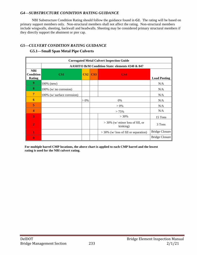
DelDOT Bridge Element Inspection Manual Bridge Management Section 233 2/1/21
G4—SUBSTRUCTURE CONDITION RATING GUIDANCE
NBI Substructure Condition Rating should follow the guidance found in G1. The rating will be based on
primary support members only. Non-structural members shall not affect the rating. Non-structural members
include wingwalls, sheeting, backwall and headwalls. Sheeting may be considered primary structural members if
they directly support the abutment or pier cap.
G5—CULVERT CONDITION RATING GUIDANCE
G5.1—Small Span Metal Pipe Culverts
Corrugated Metal Culvert Inspection Guide
AASHTO BrM Condition State: elements #240 & 847
NBI
Condition
Rating
CS1 CS2 CS3 CS4
Load Posting
9 100% (new) N/A
8 100% (w/ no corrosion) N/A
7 100% (w/ surface corrosion) N/A
6 > 0% 0% N/A
5 > 0% N/A
4 > 75% N/A
3 > 30% 15 Tons
2
> 30% (w/ minor loss of fill, or
kinking) 3 Tons
1 > 30% (w/ loss of fill or separation) Bridge Closure
0 Bridge Closure
For multiple barrel CMP locations, the above chart is applied to each CMP barrel and the lowest
rating is used for the NBI culvert rating.
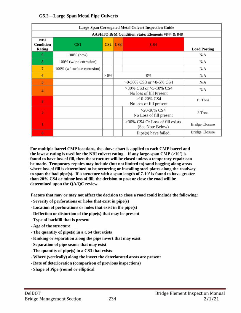
DelDOT Bridge Element Inspection Manual Bridge Management Section 234 2/1/21
G5.2—Large Span Metal Pipe Culverts
Large-Span Corrugated Metal Culvert Inspection Guide
AASHTO BrM Condition State: Elements #844 & 848
NBI
Condition
Rating
CS1 CS2 CS3 CS4
Load Posting
9 100% (new) N/A
8 100% (w/ no corrosion) N/A
7 100% (w/ surface corrosion) N/A
6 > 0% 0% N/A
5 >0-30% CS3 or >0-5% CS4 N/A
4
>30% CS3 or >5-10% CS4
No loss of fill Present N/A
3
>10-20% CS4
No loss of fill present 15 Tons
2
>20-30% CS4
No Loss of fill present 3 Tons
1
>30% CS4 Or Loss of fill exists
(See Note Below) Bridge Closure
0 Pipe(s) have failed Bridge Closure
For multiple barrel CMP locations, the above chart is applied to each CMP barrel and
the lowest rating is used for the NBI culvert rating. If any large-span CMP (>10’) is
found to have loss of fill, then the structure will be closed unless a temporary repair can
be made. Temporary repairs may include (but not limited to) sand bagging along areas
where loss of fill is determined to be occurring or installing steel plates along the roadway
to span the bad pipe(s). If a structure with a span length of 7-10’ is found to have greater
than 20% CS4 or minor loss of fill, the decision to post or close the road will be
determined upon the QA/QC review.
Factors that may or may not affect the decision to close a road could include the following:
- Severity of perforations or holes that exist in pipe(s)
- Location of perforations or holes that exist in the pipe(s)
- Deflection or distortion of the pipe(s) that may be present
- Type of backfill that is present
- Age of the structure
- The quantity of pipe(s) in a CS4 that exists
- Kinking or separation along the pipe invert that may exist
- Separation of pipe seams that may exist
- The quantity of pipe(s) in a CS3 that exists
- Where (vertically) along the invert the deteriorated areas are present
- Rate of deterioration (comparison of previous inspections)
- Shape of Pipe (round or elliptical
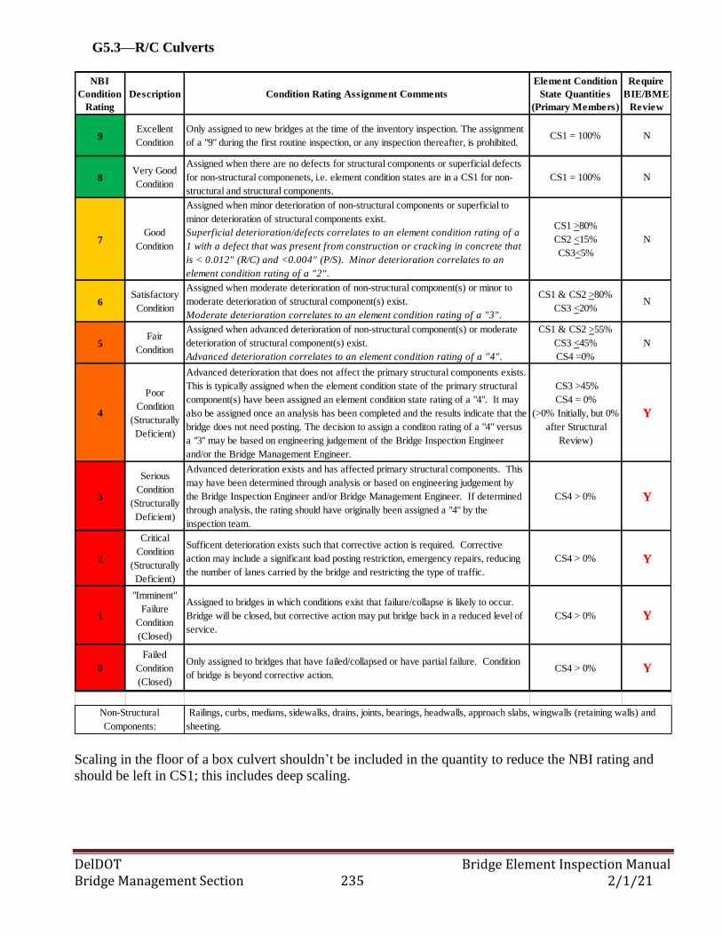
DelDOT Bridge Element Inspection Manual Bridge Management Section 235 2/1/21
G5.3—R/C Culverts
NBI
Condition
Rating
Description Condition Rating Assignment Comments
Element Condition
State Quantities
(Primary Members)
Require
BIE/BME
Review
9Excellent
Condition
Only assigned to new bridges at the time of the inventory inspection. The assignment
of a "9" during the first routine inspection, or any inspection thereafter, is prohibited. CS1 = 100% N
8Very Good
Condition
Assigned when there are no defects for structural components or superficial defects
for non-structural componenets, i.e. element condition states are in a CS1 for non-
structural and structural components.
CS1 = 100% N
7Good
Condition
Assigned when minor deterioration of non-structural components or superficial to
minor deterioration of structural components exist.
Superficial deterioration/defects correlates to an element condition rating of a
1 with a defect that was present from construction or cracking in concrete that
is < 0.012" (R/C) and <0.004" (P/S). Minor deterioration correlates to an
element condition rating of a "2".
CS1 >80%
CS2 <15%
CS3<5%
N
6Satisfactory
Condition
Assigned when moderate deterioration of non-structural component(s) or minor to
moderate deterioration of structural component(s) exist.
Moderate deterioration correlates to an element condition rating of a "3".
CS1 & CS2 >80%
CS3 <20% N
5Fair
Condition
Assigned when advanced deterioration of non-structural component(s) or moderate
deterioration of structural component(s) exist.
Advanced deterioration correlates to an element condition rating of a "4".
CS1 & CS2 >55%
CS3 <45%
CS4 =0%
N
4
Poor
Condition
(Structurally
Deficient)
Advanced deterioration that does not affect the primary structural components exists.
This is typically assigned when the element condition state of the primary structural
component(s) have been assigned an element condition state rating of a "4". It may
also be assigned once an analysis has been completed and the results indicate that the
bridge does not need posting. The decision to assign a conditon rating of a "4" versus
a "3" may be based on engineering judgement of the Bridge Inspection Engineer
and/or the Bridge Management Engineer.
CS3 >45%
CS4 = 0%
(>0% Initially, but 0%
after Structural
Review)
Y
3
Serious
Condition
(Structurally
Deficient)
Advanced deterioration exists and has affected primary structural components. This
may have been determined through analysis or based on engineering judgement by
the Bridge Inspection Engineer and/or Bridge Management Engineer. If determined
through analysis, the rating should have originally been assigned a "4" by the
inspection team.
CS4 > 0% Y
2
Critical
Condition
(Structurally
Deficient)
Sufficent deterioration exists such that corrective action is required. Corrective
action may include a significant load posting restriction, emergency repairs, reducing
the number of lanes carried by the bridge and restricting the type of traffic.
CS4 > 0% Y
1
"Imminent"
Failure
Condition
(Closed)
Assigned to bridges in which conditions exist that failure/collapse is likely to occur.
Bridge will be closed, but corrective action may put bridge back in a reduced level of
service.
CS4 > 0% Y
0
Failed
Condition
(Closed)
Only assigned to bridges that have failed/collapsed or have partial failure. Condition
of bridge is beyond corrective action.CS4 > 0% Y
Non-Structural
Components:
Railings, curbs, medians, sidewalks, drains, joints, bearings, headwalls, approach slabs, wingwalls (retaining walls) and
sheeting.
Scaling in the floor of a box culvert shouldn’t be included in the quantity to reduce the NBI rating and
should be left in CS1; this includes deep scaling.