Embed Size (px)
Citation preview
Delaunay Lofts: A Biologically Inspired Approachfor Modeling Space Filling Modular Structures
Sai Ganesh Subramaniana, Mathew Engb, Vinayak R. Krishnamurthya,∗, Ergun Aklemanb
aJ. Mike Walker ’66 Department of Mechanical EngineeringTexas A& M University, College Station, Texas, 77843
bDepartment of Visualization & Computer Science and EngineeringTexas A& M University, College Station, Texas, 77843
Abstract
In this paper, we present a simple and intuitive approach for designing space filling tiles in 3D space. Our approachis inspired by “scutoids” — shapes that were recently reported to occur in epithelial cells due to topological changesbetween the extremal (apical and basal) surfaces of epithelia. Drawing from this discovery, we develop the theoreticaland computational foundations leading to a generalized procedure for generating Delaunay Lofts — a new class ofscutoid-like shapes. Given two extremal surfaces, both with Delaunay diagrams, Delaunay Lofts are shapes that resultfrom Voronoi tessellation of all intermediate surfaces along the curves joining the vertices of Delaunay diagrams thatdefines the extremal tessellations. This, combined with the use of wallpaper symmetries allows for intuitive design ofcomplex space filling regular and semi-regular tilings in 3D space.
Keywords: Tessellation of Space, Space Filling Structures, 3D Tile Design
1. Introduction
1.1. Problem & ContextShell and volume structures are usually composed of
regular prisms (such as rectangular blocks) since theyare relatively easy to manufacture and are widely avail-able. Unfortunately, reliance on regular prisms inher-ently constrains our design space for obtaining reliableand robust structures (1; 2; 3; 4; 5). Architects currentlyinvestigate many other types of space filling modules,but their investigations are not usually systematic andfocus on only a small number of known building blocks(6). There is a need for formal approaches that enablethe design and intuitively control of a wide variety ofmodular and tile-able building blocks.
In this paper, we introduce such a conceptuallysimple and formal approach to design unconventionalbuilding blocks that can be mass-produced and resultin a space filling packing. Our approach is based ona layer-by-layer interpolation of 2D tiles using Voronoidecomposition along the third dimension in a given 3Ddomain. We call these building blocks Delaunay Lofts,since interpolation process is similar to Lofting but is
∗Corresponding author: Email: [email protected]
based on Voronoi partitioning of each 2D interpolateddomain. Such a partitioning allows for changing thetopology of the shape unlike extrude or sweep opera-tions.
1.2. Inspiration & Approach
Until recently, the biological community assumedthat cells that packed together to form thin structures(such as organ skin) were primarily prism-like shapes.This view was recently updated through the discoveryof “scutoids” — shapes that frequently occur in animalskin-cells (7). The formation of these thin (2.5D) struc-tures can be viewed as a topology changing interpola-tion through edge-collapse or vertex-split operations be-tween quadrilaterals, pentagons and hexagonal faces ofany given tessellation.
Inspired by this new discovery, we first offer a viewthat provides a dual version of this explanation. We ob-serve that scutoids could be formed by a Voronoi parti-tioning of a shell into regions based on distance to a setcurves along the thickness of the shell. This dual expla-nation is theoretically useful since (1) it provides a well-defined process to compute the boundaries of resultingstructures; and (2) it is able to naturally create curvedboundaries that is expected for resulting structures.
Preprint submitted to Computers & Graphics June 10, 2019
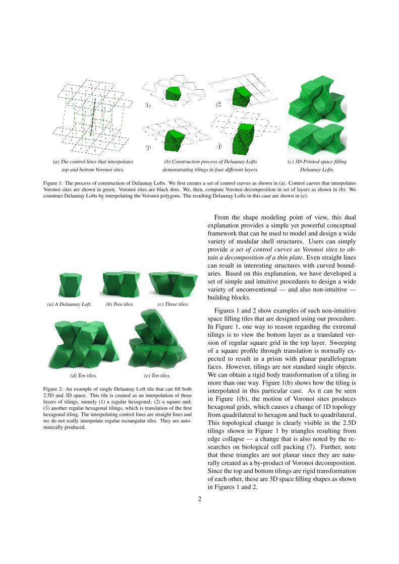
(a) The control lines that interpolates (b) Construction process of Delaunay Lofts (c) 3D-Printed space filling
top and bottom Voronoi sites. demonstrating tilings in four different layers. Delaunay Lofts.
Figure 1: The process of construction of Delaunay Lofts. We first creates a set of control curves as shown in (a). Control curves that interpolatesVoronoi sites are shown in green. Voronoi sites are black dots. We, then, compute Voronoi decomposition in set of layers as shown in (b). Weconstruct Delaunay Lofts by interpolating the Voronoi polygons. The resulting Delaunay Lofts in this case are shown in (c).
(a) A Delaunay Loft. (b) Two tiles. (c) Three tiles.
(d) Ten tiles. (e) Ten tiles.
Figure 2: An example of single Delaunay Loft tile that can fill both2.5D and 3D space. This tile is created as an interpolation of threelayers of tilings, namely (1) a regular hexagonal; (2) a square and;(3) another regular hexagonal tilings, which is translation of the firsthexagonal tiling. The interpolating control lines are straight lines andwe do not really interpolate regular rectangular tiles. They are auto-matically produced.
From the shape modeling point of view, this dualexplanation provides a simple yet powerful conceptualframework that can be used to model and design a widevariety of modular shell structures. Users can simplyprovide a set of control curves as Voronoi sites to ob-tain a decomposition of a thin plate. Even straight linescan result in interesting structures with curved bound-aries. Based on this explanation, we have developed aset of simple and intuitive procedures to design a widevariety of unconventional — and also non-intuitive —building blocks.
Figures 1 and 2 show examples of such non-intuitivespace filling tiles that are designed using our procedure.In Figure 1, one way to reason regarding the extremaltilings is to view the bottom layer as a translated ver-sion of regular square grid in the top layer. Sweepingof a square profile through translation is normally ex-pected to result in a prism with planar parallelogramfaces. However, tilings are not standard single objects.We can obtain a rigid body transformation of a tiling inmore than one way. Figure 1(b) shows how the tiling isinterpolated in this particular case. As it can be seenin Figure 1(b), the motion of Voronoi sites produceshexagonal grids, which causes a change of 1D topologyfrom quadrilateral to hexagon and back to quadrilateral.This topological change is clearly visible in the 2.5Dtilings shown in Figure 1 by triangles resulting fromedge collapse — a change that is also noted by the re-searches on biological cell packing (7). Further, notethat these triangles are not planar since they are natu-rally created as a by-product of Voronoi decomposition.Since the top and bottom tilings are rigid transformationof each other, these are 3D space filling shapes as shownin Figures 1 and 2.
2
1.3. ContributionsWe make three main contributions in this work. First,
we develop a generalized approach for constructingspace-filling tilings in 3D space. This approach is basedon two key principles, the first being the use of higher-dimensional sites (lines instead of points) for Voronoidecomposition of 3D space and the second being theuse of wallpaper symmetries to obtain repeatable tilings.Our second contribution is a method for direct controlof the topological change in Delaunay Lofts. Lastly, ourcontribution is the algorithm to practically construct De-launay Lofts in real-time at arbitrary resolutions withoutresorting to the voxelization of a domain in 3D space.This is based on distance functions induced by lines ona layer-by-layer basis.
The examples in Figures 1 and 2 demonstrate thepower of our approach for designing unusual space fill-ing structures with a simple input — a set of lines con-structed based on known symmetries. Despite the ap-parent complexity of the shapes themselves, the pro-cedure to generate a complete class of such shapes israther simple. In the rest of the paper, we first providethe biological inspiration and theoretical foundations ofthis approach in sections 2 and 3. Section 4 introducesour methodology to construct these shapes. We thendemonstrate the results obtained by our approach in asystematic manner in section 5. Finally, we discuss theimplications of this approach and potential extensionsin sections 6 and 7.
2. Related Work
A space filling shape is a cellular structure whosereplicas together can fill all of space watertight, i.e.without having any voids between them (8). Equiva-lently, a space filling shape is a cellular structure thatcan be used to generate a tessellation of space (9). While2D tessellations and space filling shapes are relativelywell-understood (subsection 3.4), problems related to3D tessellations and space filling shapes are interest-ing and have applications in a wide range of areas fromchemistry and biology to engineering and architecture(8).
A well-known anecdote to demonstrate the difficultyof 3D tessellations is that Aristotle claimed that thetetrahedron can fill space. Several efforts were madeto prove his claim (10) only to find that cube is theonly space filling Platonic solid (11). Goldberg exhaus-tively catalogued many of known space-filling polyhe-dra with a series of papers from 1972 to 1982 such as(12; 13; 14). There are only eight space-filling con-vex polyhedra and only five of them have regular faces,
namely the triangular prism, hexagonal prism, cube,truncated octahedron (15; 16), and Johnson solid gy-robifastigium (17; 18). It is also interesting that fiveof these eight space filling shapes are ”primary” paral-lelohedra (19), namely cube, hexagonal prism, rhombicdodecahedron, elongated dodecahedron, and truncatedoctahedron.
There have been many works in interpolations oftilings in 2D space(20; 21; 22; 23). Recently, there hasbeen interest in the mechanical characterization of 3Dprinted 2D tilings in the context of “sheet materials”as well (24). In this case, the sheet material is only athin extrusion of a two-dimensional tiling. Two inter-esting cases of 2D tilings relevant to our approach arethose presented by Kaplan (25) showing a wide varietyof artistic patterns using specific Voronoi site configura-tions and Rao (26) that show a systematic constructionof 2D pentagonal tilings. In fact our work, in a sense,expands on these two works to move beyond tilings in2D space to a rich design space of tilings in 3D space.
In this paper, we have developed an approach to con-struct non-polyhedral space filling shapes. Our ap-proach, which can be considered as a generalizationof parallelohedra, is inspired by a recent discovery byGomez-Galvez et al.(7) who observed that a simplepolyhedral form, which they call ”scutoids”, commonlyexists in epithelia cells in the formation of skin cells.They demonstrated that having this polyhedral form inaddition to prisms provides a natural solution to three-dimensional packing of epithelial cells. In skin cells, thetop (apical) and bottom (basal) surfaces of the cellularstructure are Voronoi patterns (as these occur frequentlydue to physical constraints) (27). Gomez-Galvez et al.observed that the fundamental problem of packing oc-curs when the polygonal shapes at apical and basal sur-faces do not match (e.g. pentagonal top and hexagonalbottom) leading to topological shift and resulting in scu-toids.
The literature on this discovery shows the occurrenceof scutoids and provides some statistical information ofwhen and how they form (7; 28; 29; 30) (Figure 3). Thereason why these shapes occur in nature is that they arethe sole enablers for a space filling packing on the skincells. These shapes, as discussed earlier, are based ona special type of (topological) interpolation between 2Dtiling patterns. These 2D tiling patterns typically con-tain simple polygonal shapes such as hexagons and pen-tagons that appear on many natural structures.
The Figure 3(a) demonstrates a usual depiction ofthe originally discovered scutoid structures obtained byedge-collapse or vertex-split operations between quadri-laterals, pentagons and hexagonal faces. This view re-
3

sults in non-planar pentagons or hexagons with straightboundaries as shown in the Figure 3(a), but it does notprovide any well-defined process to fill inside of thesenon-planar faces. Our approach is to produce space fill-ing tiles using Delaunay diagrams with wallpaper sym-metries. For instance, by choosing a stack of regularor semi-regular tilings as Delaunay triangulations forthe interpolation of vertices, we obtain a set of controlcurves that produces space filling tiles. If the top andbottom tilings are rigid transformations of each other,this process can also produce 3D space filling shapes.
Delaunay Lofts generalize scutoid-producing biolog-ical process and can create a set of shapes that containsthe aforementioned scutoids and many other shapes thatcan pack together in a space filling manner with eachother, which we call Delaunay Lofts (Figure 3(b) and(c)). By simply assembling several of these new spacefilling Delaunay Lofts, several types of shapes can becomputationally designed and physically manufacturedfor mechanical (structures), architectural (tilings), andeducational (puzzles) purposes.
Our approach to obtain space filling structures, ingeneral, can be considered 3D Voronoi decompositionof a set of curves that is closed under symmetry opera-tions. The resulted Voronoi shapes in this case are guar-anteed to be space filling. We note that our approachis also in sync with Delaunay’s original intention forthe use of Delaunay diagrams. He was the first to usesymmetry operations on points and Voronoi diagrams toproduce space filling polyhedra, which he called Stere-ohedra (31; 32). Our approach can be viewed as an ideathat stems from his general conceptual framework. We,therefore, called our approach Delaunay Lofts.
When using points, construction of 3D Voronoidecomposition is relatively simple since distances topoints guarantee to produce planar faces. On the otherhand, when we use curves or even straight lines Voronoidecomposition can produce curved faces which, in fact,makes our method interesting. However, having curvedfaces significantly complicates the algorithms to con-struct 3D Voronoi decomposition in high resolution.We, therefore, choose to deal with a subset of this gen-eral problem by: (1) decomposing the 3D domain intothin rectangular structures that consist of a discrete setof z-constant planar layers and (2) using only 2D sym-metry operations based on wallpaper patterns. The nextsection provides theoretical foundations to develop suchpractical methods to construct Delaunay Lofts.
(b)(a) (c)
Figure 3: A comparison of the original scutoid discovered by Gomel-Gomez et al. (7) (a) with the one generated by our method (b) showsthe difference between the interfacing boundaries between two dif-ferent blocks. Note that not more than 4 of these shapes can be fittogether which means these structures are not repeatable and cannotfill the space (c).
3. Theoretical Foundations
In this section, we provide the basic foundations forour approach. All the information in this section is well-known. We only provide it to establish a context for ourapproach. This background will also provide a foun-dation for the development of algorithms to constructspace-filling tiles in 3D space.
3.1. Fundamental Domain
In this paper, we present our approach as the decom-position of a 3-torus that is given as a repeated cubi-cal domain, [0, 1]3 (33) as its fundamental domain. Inother words, x ≡ x − bxc, y ≡ y − byc, and z ≡ z − bzcwhere the floor operator (bac) gives the greater integerless than or equal to a. This gives us a regular tessel-lation of 3D space. We usually assume that z does notrepeat and 0 ≤ z ≤ 1 represents a shell, i.e. a 2.5Dstructure. We further assume that curved shapes are ob-tained by a deformation of this domain such as a tensorproduct free-form volume that is defined on this cubicaldomain (34; 35). Such deformations are, of course, notstraightforward, but we purposely provide our presenta-tion using this simple domain to simplify our explana-tion without loss of generality.
3.1.1. Domain Decomposition using Control CurvesGiven the fundamental domain, our approach is sim-
ply to compute a Voronoi decomposition of this cubicaldomain into the regions based on distance to a set ofcurves given in the form of (xi = fi,x(z), yi = fi,y(z)),where i = 0, 1. . . , n. Since these curves intersect anygiven z = c constant plane only once, with a well-defined distance function, the decomposition of the 3Ddomain can be simplified as a sequence of 2D Voronoidecomposition at each planar layer, z = c, based on thedistance to a set of points (xi = fi,x(c), yi = fi,y(c)) (Seesubsection 3.2).
4

3.1.2. Interpolation CurvesWe further assume that each of these control curves
are interpolations of a set of control points given z = c j
as (xi, j, yi, j, c j). We simply choose these points to obtainany desired Voronoi decomposition in any given planarlayer. Using these points as control points of the curveswe can obtain any desired Voronoi decomposition. Forinterpolation, there is really no preference. We can evensimply use piece-wise linear interpolation.
3.2. Distance FunctionsWe observe that scutoids could be viewed as shapes
constructed from 2D Voronoi diagrams that are stackedon top of each other. The shapes of the scutoids re-sult from changes of the polygonal topology of the 2DVoronoi diagrams as we move along each interpolatedplane (z = c). In particular, edges of Voronoi cell poly-gons in different layers either collapse or split by chang-ing vertex valences. To formalize this observation, weneed to show that there actually exists a formal dis-tance function that can produce such layer by layer 2DVoronoi diagrams. In this part, we demonstrate that thisdistance function actually exists.
3.2.1. Generalized Distance FunctionLet v be a vector between two points and Lm(v) be any
linear function with m = 0, 1, . . . ,M − 1. It has beenshown that the following generalization of Minkowskidistance functions can be used to compute distance be-tween any two points (36):
d(v) =
M−1∑m=0
||Lm(v)||p
1p
(1)
where M is the number linear functions. To simplifythe discussion, we assume that the linear function Li
takes the form:
Li(v) =nm · v
sm(2)
Here, nm is a unit vector and sm > 0.
3.2.2. Circular Disk Distance FunctionLet us now consider a specific distance function in
3D where L0(v) = x, L1(v) = y, L2(v) = z/s, and p = 2,which gives us
d(x, y, z) = lims→0
√x2 + y2 +
z2
s2 (3)
In this case, the implicit shape d(x, y, z) = 1 is anellipsoid that will ultimately go to an infinitely thin cir-cular disk as s tends to zero. Unfortunately, s = 0 will
not lead to a valid distance function since d(0, 0, 0) mustbe zero for a norm and z/s is undefined when both z ands are zero. On the other hand, if s is arbitrarily close tozero, z/s is still zero when z = 0.
An important interpretation of this circular disk dis-tance is that any two points in the same layer are closerto each other than to points in layers above or below samount since d(0, 0, z) > d(x, y, 0) for (x, y) ∈ [0, 1]2
and |z| > s. This is a big advantage since we now canreduce the problem of searching for equidistant bound-aries in thin rectangular layers bounded by s in z and 0and 1 in x and y. Assume that the domain consists ofN layers in z direction and s = 1/N. Then, every layerwill be given by an implicit equality as is ≥ z ≥ (i + 1)swith i = 0, 1, . . . ,N − 1. We also assume that the inter-section of each curve with any given layer will alwaysbe confined by a circle with radius
√2s. This can eas-
ily be obtained by choosing the tangent direction nevermakes more than 450 with z direction. We also assumethat highest frequency of the control curves never ex-ceeds Nyquist limit (37). Then, we can safely samplethe curves at z = s(k+0.5) to use xi = fi,x(s(k+0.5)), yi =
fi,y(s(k + 0.5)) as 2D Voronoi sites and we can view thisdecomposition as a discretization of the cubical domaininto N number of 2D domains given as z = s(k + 0.5).
In other words, under the assumption that the 3Dstructure is thin (as characterized by the discussionabove), the 3D Voronoi decomposition reduces to 2DVoronoi decomposition of points. These assumptionscan be safely imposed in a scenario where a user is de-signing the interpolating curves and the number of sam-ples. This distance function significantly simplifies es-pecially the construction of the resulting 3D shapes byconverting the computation of 3D Voronoi decompo-sition of lines into 2D Voronoi composition of points.Based on this distance function, the construction can bedone in real time during interactive design. In order todevelop an intuitive design methodology for shape de-sign, we use Delaunay diagrams.
3.3. Delaunay DiagramIt has been shown that the computation of a Voronoi
diagram can be greatly simplified by working with itsdual, which is known as the Delaunay diagram of thegiven sites (38; 39; 40). Figure 4 shows the construc-tion of a Voronoi diagram using the Delaunay diagram.Delaunay diagrams also turn out to be useful for design-ing the proposed Delaunay Lofts since the problem ofinterpolations of polygons simplifies into that of merelyinterpolating points along a set of control curves. WithDelaunay diagrams we can precisely design the controlcurve as an interpolation curve that goes through a set
5
of critical points that defines exact locations where thepolygonal topology changes.
3.3.1. Cyclic PolygonsThe key idea behind Delaunay diagram are cyclic
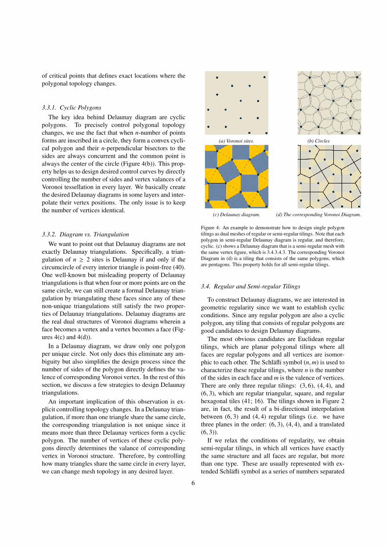
polygons. To precisely control polygonal topologychanges, we use the fact that when n-number of pointsforms are inscribed in a circle, they form a convex cycli-cal polygon and their n-perpendicular bisectors to thesides are always concurrent and the common point isalways the center of the circle (Figure 4(b)). This prop-erty helps us to design desired control curves by directlycontrolling the number of sides and vertex valances of aVoronoi tessellation in every layer. We basically createthe desired Delaunay diagrams in some layers and inter-polate their vertex positions. The only issue is to keepthe number of vertices identical.
3.3.2. Diagram vs. TriangulationWe want to point out that Delaunay diagrams are not
exactly Delaunay triangulations. Specifically, a trian-gulation of n ≥ 2 sites is Delaunay if and only if thecircumcircle of every interior triangle is point-free (40).One well-known but misleading property of Delaunaytriangulations is that when four or more points are on thesame circle, we can still create a formal Delaunay trian-gulation by triangulating these faces since any of thesenon-unique triangulations still satisfy the two proper-ties of Delaunay triangulations. Delaunay diagrams arethe real dual structures of Voronoi diagrams wherein aface becomes a vertex and a vertex becomes a face (Fig-ures 4(c) and 4(d)).
In a Delaunay diagram, we draw only one polygonper unique circle. Not only does this eliminate any am-biguity but also simplifies the design process since thenumber of sides of the polygon directly defines the va-lence of corresponding Voronoi vertex. In the rest of thissection, we discuss a few strategies to design Delaunaytriangulations.
An important implication of this observation is ex-plicit controlling topology changes. In a Delaunay trian-gulation, if more than one triangle share the same circle,the corresponding triangulation is not unique since itmeans more than three Delaunay vertices form a cyclicpolygon. The number of vertices of these cyclic poly-gons directly determines the valance of correspondingvertex in Voronoi structure. Therefore, by controllinghow many triangles share the same circle in every layer,we can change mesh topology in any desired layer.
(a) Voronoi sites. (b) Circles
(c) Delaunay diagram. (d) The corresponding Voronoi Diagram.
Figure 4: An example to demonstrate how to design single polygontilings as dual meshes of regular or semi-regular tilings. Note that eachpolygon in semi-regular Delaunay diagram is regular, and therefore,cyclic. (c) shows a Delaunay diagram that is a semi-regular mesh withthe same vertex figure, which is 3.4.3.4.3. The corresponding VoronoiDiagram in (d) is a tiling that consists of the same polygons, whichare pentagons. This property holds for all semi-regular tilings.
3.4. Regular and Semi-regular Tilings
To construct Delaunay diagrams, we are interested ingeometric regularity since we want to establish cyclicconditions. Since any regular polygon are also a cyclicpolygon, any tiling that consists of regular polygons aregood candidates to design Delaunay diagrams.
The most obvious candidates are Euclidean regulartilings, which are planar polygonal tilings where allfaces are regular polygons and all vertices are isomor-phic to each other. The Schlafli symbol (n,m) is used tocharacterize these regular tilings, where n is the numberof the sides in each face and m is the valence of vertices.There are only three regular tilings: (3, 6), (4, 4), and(6, 3), which are regular triangular, square, and regularhexagonal tiles (41; 16). The tilings shown in Figure 2are, in fact, the result of a bi-directional interpolationbetween (6, 3) and (4, 4) regular tilings (i.e. we havethree planes in the order: (6, 3), (4, 4), and a translated(6, 3)).
If we relax the conditions of regularity, we obtainsemi-regular tilings, in which all vertices have exactlythe same structure and all faces are regular, but morethan one type. These are usually represented with ex-tended Schlafli symbol as a series of numbers separated
6
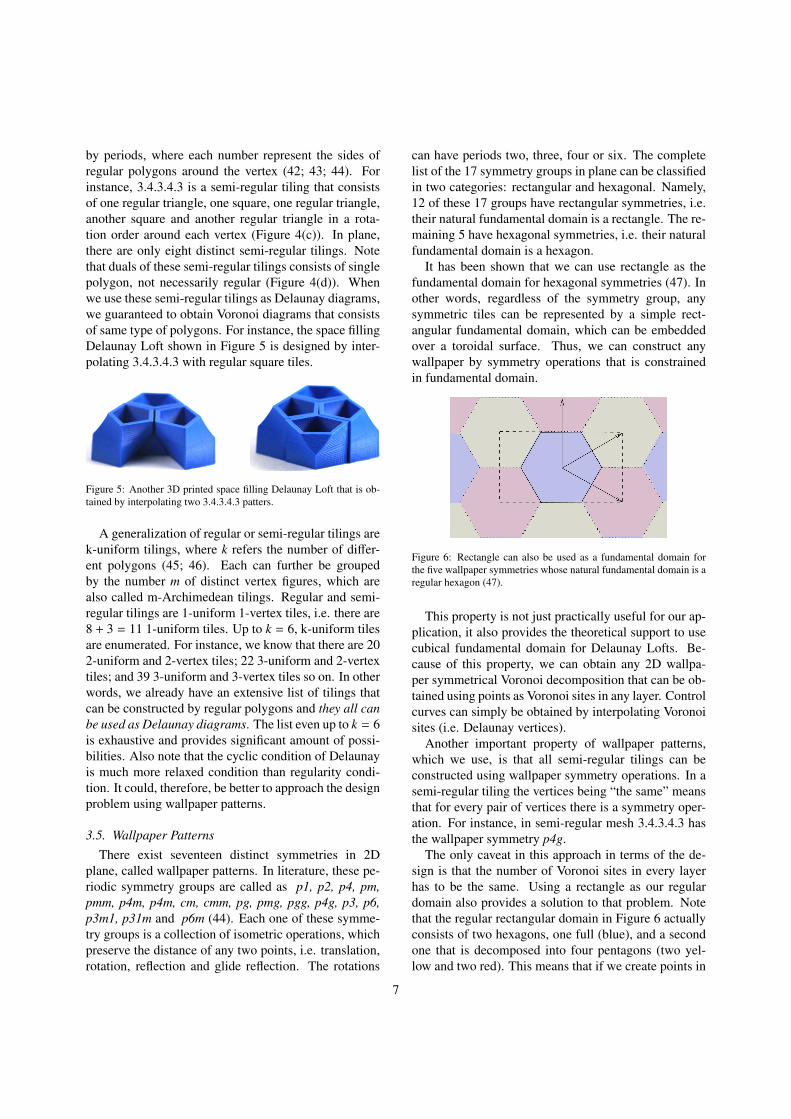
by periods, where each number represent the sides ofregular polygons around the vertex (42; 43; 44). Forinstance, 3.4.3.4.3 is a semi-regular tiling that consistsof one regular triangle, one square, one regular triangle,another square and another regular triangle in a rota-tion order around each vertex (Figure 4(c)). In plane,there are only eight distinct semi-regular tilings. Notethat duals of these semi-regular tilings consists of singlepolygon, not necessarily regular (Figure 4(d)). Whenwe use these semi-regular tilings as Delaunay diagrams,we guaranteed to obtain Voronoi diagrams that consistsof same type of polygons. For instance, the space fillingDelaunay Loft shown in Figure 5 is designed by inter-polating 3.4.3.4.3 with regular square tiles.
Figure 5: Another 3D printed space filling Delaunay Loft that is ob-tained by interpolating two 3.4.3.4.3 patters.
A generalization of regular or semi-regular tilings arek-uniform tilings, where k refers the number of differ-ent polygons (45; 46). Each can further be groupedby the number m of distinct vertex figures, which arealso called m-Archimedean tilings. Regular and semi-regular tilings are 1-uniform 1-vertex tiles, i.e. there are8 + 3 = 11 1-uniform tiles. Up to k = 6, k-uniform tilesare enumerated. For instance, we know that there are 202-uniform and 2-vertex tiles; 22 3-uniform and 2-vertextiles; and 39 3-uniform and 3-vertex tiles so on. In otherwords, we already have an extensive list of tilings thatcan be constructed by regular polygons and they all canbe used as Delaunay diagrams. The list even up to k = 6is exhaustive and provides significant amount of possi-bilities. Also note that the cyclic condition of Delaunayis much more relaxed condition than regularity condi-tion. It could, therefore, be better to approach the designproblem using wallpaper patterns.
3.5. Wallpaper PatternsThere exist seventeen distinct symmetries in 2D
plane, called wallpaper patterns. In literature, these pe-riodic symmetry groups are called as p1, p2, p4, pm,pmm, p4m, p4m, cm, cmm, pg, pmg, pgg, p4g, p3, p6,p3m1, p31m and p6m (44). Each one of these symme-try groups is a collection of isometric operations, whichpreserve the distance of any two points, i.e. translation,rotation, reflection and glide reflection. The rotations
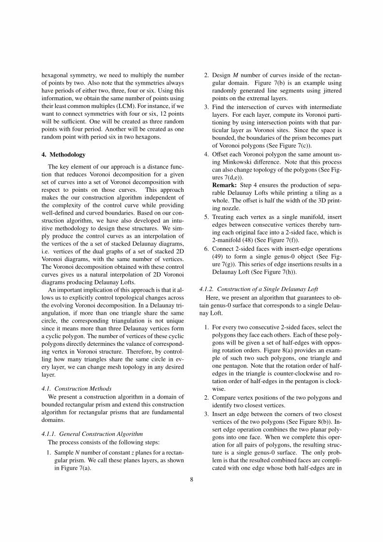
can have periods two, three, four or six. The completelist of the 17 symmetry groups in plane can be classifiedin two categories: rectangular and hexagonal. Namely,12 of these 17 groups have rectangular symmetries, i.e.their natural fundamental domain is a rectangle. The re-maining 5 have hexagonal symmetries, i.e. their naturalfundamental domain is a hexagon.
It has been shown that we can use rectangle as thefundamental domain for hexagonal symmetries (47). Inother words, regardless of the symmetry group, anysymmetric tiles can be represented by a simple rect-angular fundamental domain, which can be embeddedover a toroidal surface. Thus, we can construct anywallpaper by symmetry operations that is constrainedin fundamental domain.
Figure 6: Rectangle can also be used as a fundamental domain forthe five wallpaper symmetries whose natural fundamental domain is aregular hexagon (47).
This property is not just practically useful for our ap-plication, it also provides the theoretical support to usecubical fundamental domain for Delaunay Lofts. Be-cause of this property, we can obtain any 2D wallpa-per symmetrical Voronoi decomposition that can be ob-tained using points as Voronoi sites in any layer. Controlcurves can simply be obtained by interpolating Voronoisites (i.e. Delaunay vertices).
Another important property of wallpaper patterns,which we use, is that all semi-regular tilings can beconstructed using wallpaper symmetry operations. In asemi-regular tiling the vertices being “the same” meansthat for every pair of vertices there is a symmetry oper-ation. For instance, in semi-regular mesh 3.4.3.4.3 hasthe wallpaper symmetry p4g.
The only caveat in this approach in terms of the de-sign is that the number of Voronoi sites in every layerhas to be the same. Using a rectangle as our regulardomain also provides a solution to that problem. Notethat the regular rectangular domain in Figure 6 actuallyconsists of two hexagons, one full (blue), and a secondone that is decomposed into four pentagons (two yel-low and two red). This means that if we create points in
7
hexagonal symmetry, we need to multiply the numberof points by two. Also note that the symmetries alwayshave periods of either two, three, four or six. Using thisinformation, we obtain the same number of points usingtheir least common multiples (LCM). For instance, if wewant to connect symmetries with four or six, 12 pointswill be sufficient. One will be created as three randompoints with four period. Another will be created as onerandom point with period six in two hexagons.
4. Methodology
The key element of our approach is a distance func-tion that reduces Voronoi decomposition for a givenset of curves into a set of Voronoi decomposition withrespect to points on those curves. This approachmakes the our construction algorithm independent ofthe complexity of the control curve while providingwell-defined and curved boundaries. Based on our con-struction algorithm, we have also developed an intu-itive methodology to design these structures. We sim-ply produce the control curves as an interpolation ofthe vertices of the a set of stacked Delaunay diagrams,i.e. vertices of the dual graphs of a set of stacked 2DVoronoi diagrams, with the same number of vertices.The Voronoi decomposition obtained with these controlcurves gives us a natural interpolation of 2D Voronoidiagrams producing Delaunay Lofts.
An important implication of this approach is that it al-lows us to explicitly control topological changes acrossthe evolving Voronoi decomposition. In a Delaunay tri-angulation, if more than one triangle share the samecircle, the corresponding triangulation is not uniquesince it means more than three Delaunay vertices forma cyclic polygon. The number of vertices of these cyclicpolygons directly determines the valance of correspond-ing vertex in Voronoi structure. Therefore, by control-ling how many triangles share the same circle in ev-ery layer, we can change mesh topology in any desiredlayer.
4.1. Construction MethodsWe present a construction algorithm in a domain of
bounded rectangular prism and extend this constructionalgorithm for rectangular prisms that are fundamentaldomains.
4.1.1. General Construction AlgorithmThe process consists of the following steps:
1. Sample N number of constant z planes for a rectan-gular prism. We call these planes layers, as shownin Figure 7(a).
2. Design M number of curves inside of the rectan-gular domain. Figure 7(b) is an example usingrandomly generated line segments using jitteredpoints on the extremal layers.
3. Find the intersection of curves with intermediatelayers. For each layer, compute its Voronoi parti-tioning by using intersection points with that par-ticular layer as Voronoi sites. Since the space isbounded, the boundaries of the prism becomes partof Voronoi polygons (See Figure 7(c)).
4. Offset each Voronoi polygon the same amount us-ing Minkowski difference. Note that this processcan also change topology of the polygons (See Fig-ures 7(d,e)).Remark: Step 4 ensures the production of sepa-rable Delaunay Lofts while printing a tiling as awhole. The offset is half the width of the 3D print-ing nozzle.
5. Treating each vertex as a single manifold, insertedges between consecutive vertices thereby turn-ing each original face into a 2-sided face, which is2-manifold (48) (See Figure 7(f)).
6. Connect 2-sided faces with insert-edge operations(49) to form a single genus-0 object (See Fig-ure 7(g)). This series of edge insertions results in aDelaunay Loft (See Figure 7(h)).
4.1.2. Construction of a Single Delaunay LoftHere, we present an algorithm that guarantees to ob-
tain genus-0 surface that corresponds to a single Delau-nay Loft.
1. For every two consecutive 2-sided faces, select thepolygons they face each others. Each of these poly-gons will be given a set of half-edges with oppos-ing rotation orders. Figure 8(a) provides an exam-ple of such two such polygons, one triangle andone pentagon. Note that the rotation order of half-edges in the triangle is counter-clockwise and ro-tation order of half-edges in the pentagon is clock-wise.
2. Compare vertex positions of the two polygons andidentify two closest vertices.
3. Insert an edge between the corners of two closestvertices of the two polygons (See Figure 8(b)). In-sert edge operation combines the two planar poly-gons into one face. When we complete this oper-ation for all pairs of polygons, the resulting struc-ture is a single genus-0 surface. The only prob-lem is that the resulted combined faces are compli-cated with one edge whose both half-edges are in
8

(a) Initial Layers. (b) The control curves. (c) Voronoi decomposition of layers. (d) Offset polygons.
(e) Offset polygons for one Voronoi Loft. (f) Construction of 2D sided (g) Connecting 2-sided faces (h) Final Voronoi Loft.
(i.e. 2-manifold) faces. by inserting edges.
Figure 7: Construction Algorithm over a bounded rectangular prism domain.
(a) Initial polygon-
pair with opposite
rotation order
(b) Inserting an
edge to combine
the two polygons
(c) Parametri-
zation of corners
of combined face
Figure 8: An example of connecting two polygons, a pentagon andand a triangle, by inserting edges. Half-edges are shown as arrowsand edges (i.e. two half-edges) are shown as line segments.At the endof a process of a series of edge insert operations, we obtain trianglesand quadrilaterals by subdividing combined face.
the same face. Therefore, there is a need for sub-dividing this face into geometrically well-definedfaces, i.e. triangles and quadrilaterals.Remark: It is easy to subdivide the combined faceusing a series of insert edge operations. Since aninsert edge operation that is applied to a 2-manifoldmesh always creates another 2-manifold, we cannever get non-manifold. On the other hand, if oneis not careful, it is always possible to introducetopological noise, i.e. one can increase genus byintroducing holes and handles (50). Next step pro-vides an algorithm to avoid that guarantees genus-0surface.
4. Assign two parameters, 0 ≥ u ≥ 1 and 0 ≥ v ≥
1, along the perimeter of each polygon, one incounter-clockwise and another in clockwise, start-ing from one side of the inserted edge and endingthe other side of inserted edge. This assigns a para-metric position to each corner of the polygon ui andu j as follows:
un =1L
n−1∑i=0
Li , vm =1D
m−1∑i=0
Di (4)
where Li and Di are length of half-edges in poly-
gons 1 and 2 respectively; L =
N−1∑i=0
Li, D =
M−1∑i=0
Di,
and N ≥ M.5. To guarantee that the operation does not produce
topological noise, i.e. not to increase genus, edgesmust be inserted between corners in the same face.This could be done a variety of the ways. The fol-lowing pseudo-code provides the algorithm we useto obtain genus-0 Delaunay Lofts:
4.1.3. Construction with Fundamental DomainThis extension is straightforward. We use nine copies
of fundamental domain to form a single rectangularprism and compute Delaunay Lofts as in previous sub-section. However, we only use Delaunay Lofts in thecenter rectangular prism .
9
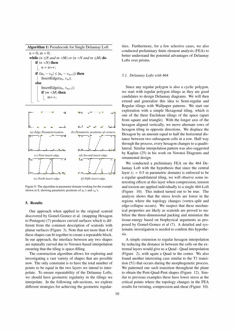
Algorithm 1: Pseudocode for Single Delaunay Loft
n = 0; m = 0;while (n ≤N and m <M) or (n <N and m ≤M) do
if (n <N) thenn = n++;
if (|un − vm| ≤ |un − vm+1|) thenInsertEdge(un, vm);
elseInsertEdge(un, vm+1);if (m <M) then
m++;
(a) Edge Parameterization. (b) Parametric positions of corners.
(c) First insert edge. (d) Second insert edge.
(e) Forth insert edge. (f) Fifth insert edge.
Figure 9: The algorithm in parameter domain working for the exampleshown in 8, showing parametric positions of un’s and vm’s.
5. Results
Our approach when applied to the original scutoiddiscovered by Gomel-Gomez et al. (mapping Hexagonto Pentagon) (7) produces curved surfaces which is dif-ferent from the common description of scutoids withplanar surfaces (Figure 3). Note that not more than 4 ofthese shapes can fit together to create a repeatable block.In our approach, the interface between any two shapesare naturally curved due to Voronoi-based interpolationensuring that the tiling is space-filling.
The construction algorithm allows for exploring andinvestigating a vast variety of shapes that are possiblenow. The only constraint is to have the total number ofpoints to be equal in the two layers we intend to inter-polate. To ensure repeatability of the Delaunay Lofts,we should have geometric regularity in the tilings weinterpolate. In the following sub-sections, we exploredifferent strategies for achieving the geometric regular-
ities. Furthermore, for a few selective cases, we alsoconducted preliminary finite element analysis (FEA) tobetter understand the potential advantages of DelaunayLofts over prisms.
5.1. Delaunay Lofts with 464
Since any regular polygon is also a cyclic polygon,we start with regular polygon tilings as they are goodcandidates to design Delaunay diagrams. We will thenextend and generalize this idea to Semi-regular andRegular tilings with Wallpaper patterns. We start ourexploration with a simple Hexagonal tiling, which isone of the three Euclidean tilings of the space (apartfrom square and triangle). With the longer axis of thehexagon aligned vertically, we move alternate rows ofhexagon tiling in opposite directions. We displace theHexagon by an amount equal to half the horizontal dis-tance between two subsequent cells in a row. Half waythrough the process, every hexagon changes to a quadri-lateral. Similar interpolation pattern was also suggestedby Kaplan (25) in his work on Voronoi Diagrams andornamental design.
We conducted a preliminary FEA on the 464 De-launay Loft with the hypothesis that since the centrallayer (z = 0.5 in parametric domain) is enforced to bea regular quadrilateral tiling, we will observe some in-teresting effects at this layer when compression, tensionand torsion are applied individually to a single 464-Loft(Figure 10). This indeed turned out to be true. Theanalysis shows that the stress levels are lower in theregions where the topology changes (vertex-split andedge-collapse occurs). We suspect that these mechan-ical properties are likely as scutoids are proved to sta-bilize the three-dimensional packing and minimize thetissue-energy based on biophysical arguments as pro-posed by Gomel-Gomez et al (7). A detailed and sys-tematic investigation is needed to confirm this hypothe-sis.
A simple extension to regular hexagon interpolationby reducing the distance in between the cells on the ex-tremal layers would give us a Quad - Quad interpolation(Figure 2), with again a Quad in the center. We alsofound another interesting case similar to the T1 transi-tion (51) that occurs during the morphogenetic process.We patterned one such transition throughout the planeto obtain the Pent-Quad-Pent shapes (Figure 12). Sim-ilar to previous examples these have lower stress at thecritical points where the topology changes in the FEAresults for twisting, compression and shear (Figure 10).
10
(a) Min: 3.2121e6
Max: 1.5717e8(c) Min: 7.6954e6
Max: 1.0641e10
(d) Min: 1.5791e7
Max: 5.98e8 (e) Min: 0.01738
Max: 10.995
(f) Min: 1.53e7
Max: 1.6443e10
(b) Min: 1.2
Max: 14.99
Max*
Min*
* Range is adjusted for every FEA to make the stress distribution visible
0.00
1.00 (cm)
* All the Min and Max values are in Pascal
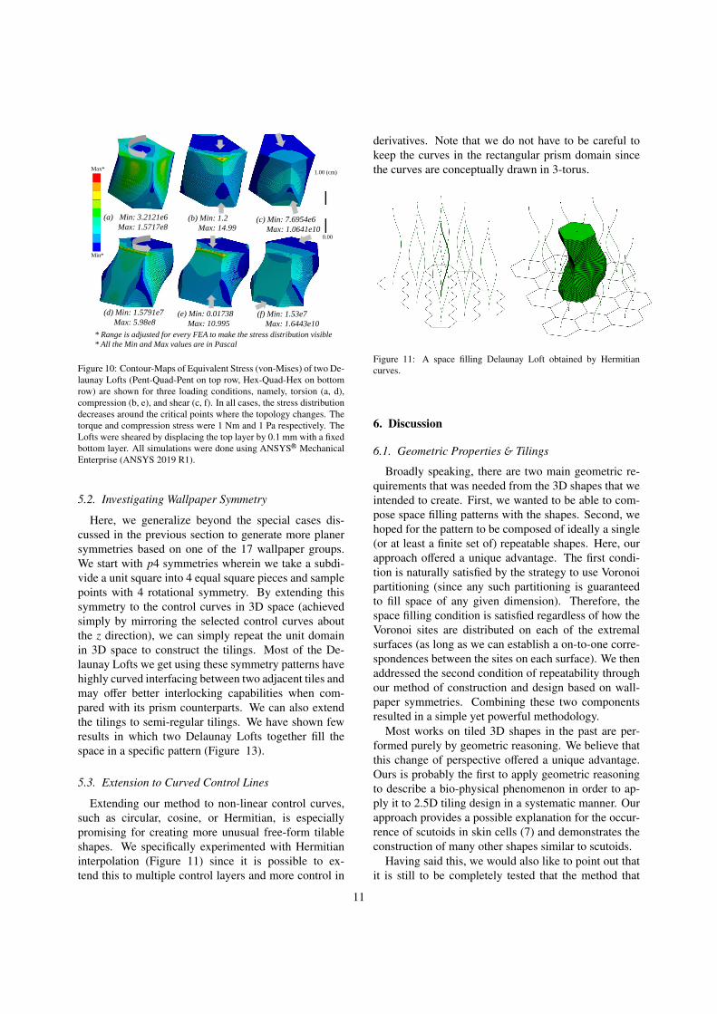
Figure 10: Contour-Maps of Equivalent Stress (von-Mises) of two De-launay Lofts (Pent-Quad-Pent on top row, Hex-Quad-Hex on bottomrow) are shown for three loading conditions, namely, torsion (a, d),compression (b, e), and shear (c, f). In all cases, the stress distributiondecreases around the critical points where the topology changes. Thetorque and compression stress were 1 Nm and 1 Pa respectively. TheLofts were sheared by displacing the top layer by 0.1 mm with a fixedbottom layer. All simulations were done using ANSYSR© MechanicalEnterprise (ANSYS 2019 R1).
5.2. Investigating Wallpaper Symmetry
Here, we generalize beyond the special cases dis-cussed in the previous section to generate more planersymmetries based on one of the 17 wallpaper groups.We start with p4 symmetries wherein we take a subdi-vide a unit square into 4 equal square pieces and samplepoints with 4 rotational symmetry. By extending thissymmetry to the control curves in 3D space (achievedsimply by mirroring the selected control curves aboutthe z direction), we can simply repeat the unit domainin 3D space to construct the tilings. Most of the De-launay Lofts we get using these symmetry patterns havehighly curved interfacing between two adjacent tiles andmay offer better interlocking capabilities when com-pared with its prism counterparts. We can also extendthe tilings to semi-regular tilings. We have shown fewresults in which two Delaunay Lofts together fill thespace in a specific pattern (Figure 13).
5.3. Extension to Curved Control Lines
Extending our method to non-linear control curves,such as circular, cosine, or Hermitian, is especiallypromising for creating more unusual free-form tilableshapes. We specifically experimented with Hermitianinterpolation (Figure 11) since it is possible to ex-tend this to multiple control layers and more control in
derivatives. Note that we do not have to be careful tokeep the curves in the rectangular prism domain sincethe curves are conceptually drawn in 3-torus.
Figure 11: A space filling Delaunay Loft obtained by Hermitiancurves.
6. Discussion
6.1. Geometric Properties & Tilings
Broadly speaking, there are two main geometric re-quirements that was needed from the 3D shapes that weintended to create. First, we wanted to be able to com-pose space filling patterns with the shapes. Second, wehoped for the pattern to be composed of ideally a single(or at least a finite set of) repeatable shapes. Here, ourapproach offered a unique advantage. The first condi-tion is naturally satisfied by the strategy to use Voronoipartitioning (since any such partitioning is guaranteedto fill space of any given dimension). Therefore, thespace filling condition is satisfied regardless of how theVoronoi sites are distributed on each of the extremalsurfaces (as long as we can establish a on-to-one corre-spondences between the sites on each surface). We thenaddressed the second condition of repeatability throughour method of construction and design based on wall-paper symmetries. Combining these two componentsresulted in a simple yet powerful methodology.
Most works on tiled 3D shapes in the past are per-formed purely by geometric reasoning. We believe thatthis change of perspective offered a unique advantage.Ours is probably the first to apply geometric reasoningto describe a bio-physical phenomenon in order to ap-ply it to 2.5D tiling design in a systematic manner. Ourapproach provides a possible explanation for the occur-rence of scutoids in skin cells (7) and demonstrates theconstruction of many other shapes similar to scutoids.
Having said this, we would also like to point out thatit is still to be completely tested that the method that
11

Figure 12: The three patterns (left to right) show the Voronoi diagrams from the bottom, middle and the top layer of interpolation. In the first rowwe show the 464 Delaunay Lofts and second row shows the Delaunay Lofts obtained by interpolating 3.4.3.4.3 patterns.
we propose here for constructing Delaunay Lofts canindeed also be used to model the original scutoids. Thekey gap that needs to be addressed for this is to com-pare the actual geometry (and not the idealized modelshown in Figure 3) that is experimentally obtained withone constructed using our approach with the same initialconditions as the bio-physical case.
6.2. Geometric Design SpaceThe design space of shapes that can be composed us-
ing our approach is unusually rich. This is due to threefacts. First, the construction algorithm does not assumeany specific shape of the control curves — as long asthey intersect each slicing plane at a unique point thusmaintaining the number of sites per slice. This aloneprovides many possibilities in terms of obtaining seem-ingly complex geometries. Second, the 17 wallpapersymmetries result in several possibilities in terms of thetiling configurations that may be possible with our ap-proach. Finally, the distance functions utilized in allour examples are only L2-norms. Generalizing to Lp-norms will lead to even more unusual shapes that wehave currently demonstrated. Having said this, we havecurrently exposed only a limited set of repeatable tilesas examples in the paper. We are currently developing amore systematic geometric kernel and interactive soft-ware to explore the complete design space of DelaunayLofts.
7. Conclusion and Future Work
In this paper, we presented an approach to constructand eventually design a new class of tilings in 3D space.
We have developed an algorithm that takes as input twoplanes containing Voronoi tessellations based on somedistribution of points and interpolates the tilings be-tween these given planes. The volumetric structures ob-tained through this interpolation result in the occurrenceof Delaunay Lofts. There are several variations of howthis interpolation can lead to a variety of such Lofts.
The future work is to investigate the power of shapesthat are created by our bio-inspired design approach interms of withstanding stress, torsion or fatigue. If theseapproaches can create powerful shapes in terms of with-standing stress , torsion and fatigue, this approach couldbe arguably applied to come up with completely new de-signs and structures that could have greater strength. Anadvantage of our approach is that it can easily be usedin combinatorial optimization. Therefore, this approachcould take the industry to the next level of material op-timization and unveil endless possibilities of geometricdesigns with Delaunay Lofts.
8. Acknowledgments
We thank the reviewers for their valuable feedbackand comments. This work was supported by the TexasA&M Engineering Experiment Station and the J. MikeWalker ’66 Department of Mechanical Engineering atTexas A&M University.[1] E. Whiting, J. Ochsendorf, F. Durand, Procedural model-
ing of structurally-sound masonry buildings, ACM Trans.Graph. 28 (5) (2009) 112:1–112:9. doi:10.1145/1618452.
1618458.[2] M. Deuss, D. Panozzo, E. Whiting, Y. Liu, P. Block, O. Sorkine-
Hornung, M. Pauly, Assembling self-supporting structures,ACM Trans. Graph. 33 (6) (2014) 214:1–214:10. doi:10.
1145/2661229.2661266.
12
(a)
(b)
(c)
(d)
(e)
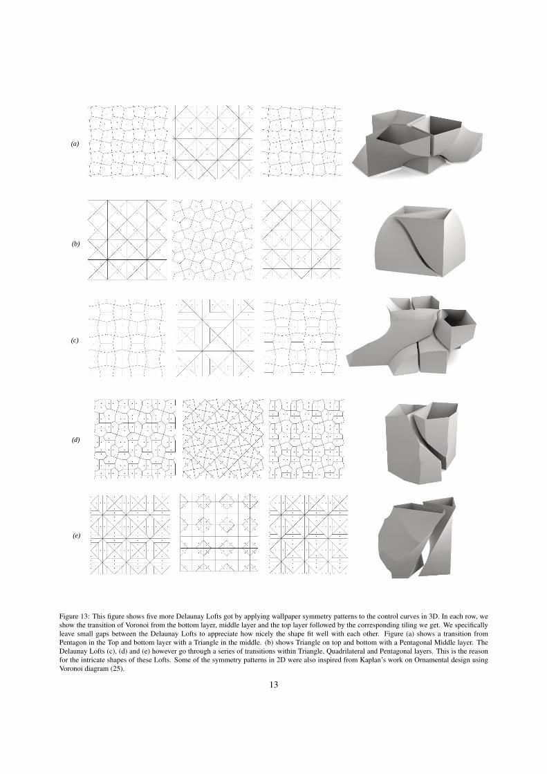
Figure 13: This figure shows five more Delaunay Lofts got by applying wallpaper symmetry patterns to the control curves in 3D. In each row, weshow the transition of Voronoi from the bottom layer, middle layer and the top layer followed by the corresponding tiling we get. We specificallyleave small gaps between the Delaunay Lofts to appreciate how nicely the shape fit well with each other. Figure (a) shows a transition fromPentagon in the Top and bottom layer with a Triangle in the middle. (b) shows Triangle on top and bottom with a Pentagonal Middle layer. TheDelaunay Lofts (c), (d) and (e) however go through a series of transitions within Triangle, Quadrilateral and Pentagonal layers. This is the reasonfor the intricate shapes of these Lofts. Some of the symmetry patterns in 2D were also inspired from Kaplan’s work on Ornamental design usingVoronoi diagram (25).
13
[3] E. Whiting, H. Shin, R. Wang, J. Ochsendorf, F. Durand,Structural optimization of 3d masonry buildings, ACM Trans.Graph. 31 (6) (2012) 159:1–159:11. doi:10.1145/2366145.2366178.
[4] H. V. Shin, C. F. Porst, E. Vouga, J. Ochsendorf, F. Durand,Reconciling elastic and equilibrium methods for static analysis,ACM Trans. Graph. 35 (2) (2016) 13:1–13:16. doi:10.1145/2835173.
[5] M. Kilian, D. Pellis, J. Wallner, H. Pottmann, Material-minimizing forms and structures, ACM Trans. Graphics 36 (6)(2017) article 173, proc. SIGGRAPH Asia. doi:http://dx.
doi.org/10.1145/3130800.3130827.[6] G. Fallacara, Toward a stereotomic design: Experimental con-
structions and didactic experiences, in: Proceedings of the ThirdInternational Congress on Construction History, 2009, p. 553.
[7] P. Gomez-Galvez, P. Vicente-Munuera, A. Tagua, C. Forja,A. M. Castro, M. Letran, A. Valencia-Exposito, C. Grima,M. Bermudez-Gallardo, O. Serrano-Perez-Higueras, et al., Scu-toids are a geometrical solution to three-dimensional packing ofepithelia, Nature communications 9 (1) (2018) 2960.
[8] A. L. Loeb, Space-filling polyhedra, in: Space Structures,Springer, 1991, pp. 127–132.
[9] B. Grunbaum, G. C. Shephard, Tilings with congruent tiles, Bul-letin of the American Mathematical Society 3 (3) (1980) 951–973.
[10] M. Senechal, Which tetrahedra fill space?, Mathematics Maga-zine 54 (5) (1981) 227–243.
[11] M. Gardner, Sixth book of mathematical games from ScientificAmerican, WH Freeman San Francisco, 1971.
[12] M. Goldberg, The space-filling pentahedra, Journal of Combi-natorial Theory, Series A 13 (3) (1972) 437–443.
[13] M. Goldberg, Convex polyhedral space-fillers of more thantwelve faces, Geometriae Dedicata 8 (4) (1979) 491–500.
[14] M. Goldberg, On the space-filling enneahedra, Geometriae Ded-icata 12 (3) (1982) 297–306.
[15] R. E. Williams, Space-filling polyhedron: its relation to aggre-gates of soap bubbles, plant cells, and metal crystallites, Science161 (3838) (1968) 276–277.
[16] R. Williams, The geometrical foundation of natural structure: Asource book of design, Dover New York, 1979.
[17] N. W. Johnson, Convex polyhedra with regular faces, CanadianJournal of Mathematics 18 (1966) 169–200.
[18] S. Alvarez, The gyrobifastigium, not an uncommon shape inchemistry, Coordination Chemistry Reviews 350 (2017) 3–13.
[19] H. S. M. Coxeter, Regular polytopes, Courier Corporation,1973.
[20] T. W. Sederberg, E. Greenwood, A physically based approachto 2–d shape blending, ACM SIGGRAPH computer graphics26 (2) (1992) 25–34.
[21] T. W. Sederberg, P. Gao, G. Wang, H. Mu, 2-d shape blending:an intrinsic solution to the vertex path problem, Proceedings ofthe 20th annual conference on Computer graphics and interac-tive techniques (1993) 15–18.
[22] M. Alexa, D. Cohen-Or, D. Levin, As-rigid-as-possible shapeinterpolation, in: Proceedings of the 27th annual confer-ence on Computer graphics and interactive techniques, ACMPress/Addison-Wesley Publishing Co., 2000, pp. 157–164.
[23] G. Turk, J. F. O’brien, Shape transformation using variationalimplicit functions, in: ACM SIGGRAPH 2005 Courses, ACM,2005, p. 13.
[24] C. Schumacher, S. Marschner, M. Cross, B. Thomaszewski, Me-chanical characterization of structured sheet materials, ACMTrans. Graph. 37 (4) (2018) 148:1–148:15. doi:10.1145/
3197517.3201278.[25] C. S. Kaplan, Voronoi diagrams and ornamental design, in: in
The First Annual Symposium of the International Society for theArts, Mathematics, and Architecture, 2000, pp. 277–283.
[26] M. Rao, Exhaustive search of convex pentagons which tile theplane, arXiv preprint arXiv:1708.00274 (2017).
[27] H. Honda, Description of cellular patterns by dirichlet do-mains: The two-dimensional case, Journal of Theoretical Bi-ology 72 (3) (1978) 523 – 543.
[28] G. Blanchard, A 3d cell shape that enables tube formation(2018).
[29] C. M. Nelson, Epithelial packing: Even the best of friends mustpart, Current Biology 28 (20) (2018) R1197–R1200.
[30] A. Mughal, S. Cox, D. Weaire, S. Burke, S. Hutzler, Demon-stration and interpretation of” scutoid” cells in a quasi-2d soapfroth, arXiv preprint arXiv:1809.08421.
[31] B. N. Delaunay, N. N. Sandakova, Theory of stereohedra, TrudyMatematicheskogo Instituta imeni VA Steklova 64 (1961) 28–51.
[32] M. W. Schmitt, On space groups and dirichlet–voronoi stereo-hedra, Ph.D. thesis, Berlin: Freien Universitt Berlin (2016).
[33] J.-P. Luminet, B. F. Roukema, Topology of the universe: Theoryand observation, in: Theoretical and Observational Cosmology,Springer, 1999, pp. 117–156.
[34] E. Cohen, R. F. Riesenfeld, G. Elber, Geometric modeling withsplines: an introduction, AK Peters/CRC Press, 2001.
[35] F. Massarwi, G. Elber, A b-spline based framework for volu-metric object modeling, Computer-Aided Design 78 (C) (2016)36–47.
[36] E. Akleman, J. Chen, Generalized distance functions, in: Pro-ceedings Shape Modeling International’99. International Con-ference on Shape Modeling and Applications, IEEE, 1999, pp.72–79.
[37] H. Nyquist, Certain topics in telegraph transmission theory,Transactions of the American Institute of Electrical Engineers47 (2) (1928) 617–644.
[38] B. N. Boots, Delaunay triangles: an alternative approach topoint pattern analysis, Proceedings of the Association of Amer-ican Geographers 6 (1974) 26–29.
[39] D. F. Watson, Computing the n-dimensional delaunay tessella-tion with application to voronoi polytopes, The computer jour-nal 24 (2) (1981) 167–172.
[40] L. Guibas, J. Stolfi, Primitives for the manipulation of generalsubdivisions and the computation of voronoi, ACM transactionson graphics (TOG) 4 (2) (1985) 74–123.
[41] I. Stewart, Game, set and math: enigmas and conundrums,Courier Corporation, 2007.
[42] B. Grunbaum, G. C. Shephard, Tilings by regular polygons,Mathematics Magazine 50 (5) (1977) 227–247.
[43] B. Grunbaum, G. Shephard, The ninety-one types of isogonaltilings in the plane, Transactions of the American MathematicalSociety 242 (1978) 335–353.
[44] B. Grunbaum, G. C. Shephard, Tilings and patterns, Freeman,1987.
[45] D. Chavey, Tilings by regular polygons ii a catalog of tilings,in: Symmetry 2, Elsevier, 1989, pp. 147–165.
[46] N. Lenngren, k-uniform tilings by regular polygons, www.diva-portal.org/smash/get/diva2:444746/FULLTEXT01.pdf (2009).
[47] E. Akleman, J. Chen, B. Meric, Web-based intuitive and effec-tive design of symmetric tiles, Proceedings of ACM Multimedia21 (4) (2000) 100–108.
[48] V. Srinivasan, E. Akleman, J. Chen, Interactive constructionof multi-segment curved handles, in: Computer Graphics andApplications, 2002. Proceedings. 10th Pacific Conference on,IEEE, 2002, pp. 429–430.
[49] E. Akleman, J. Chen, V. Srinivasan, A minimal and completeset of operators for the development of robust manifold mesh
14
modelers, Graphical models 65 (5) (2003) 286–304.[50] I. Guskov, Z. J. Wood, Topological noise removal, 2001 Graph-
ics Interface Proceedings: Ottawa, Canada (2001) 19.[51] M. Tada, C.-P. Heisenberg, Convergent extension: Using collec-
tive cell migration and cell intercalation to shape embryos, De-velopment (Cambridge, England) 139 (2012) 3897–904. doi:
10.1242/dev.073007.
15


![Using Transactions in Delaunay Mesh Generation2. Delaunay Mesh Generation A Delaunay mesh is a mesh over a set of points which satisfies the Delaunay property [4]. This property,](https://img.pdfslide.us/doc/110x75/5e78132d55760c30656ba589/using-transactions-in-delaunay-mesh-generation-2-delaunay-mesh-generation-a-delaunay.jpg)