Embed Size (px)
Citation preview
DEFORMATION FORECAST OF FLEXIBLE MATERIAL
PROCESS BY SPLINE FINITE ELEMENT METHOD AND
APPLICATION
Deng Yaohua, Li Bingjing, Chen Sicheng, Chen Jiyuan, Wu Liming
School of Information Engineering
Guangdong University of Technology, Guangzhou
Guangdong ,China
Email:[email protected]
Submitted: Oct. 15, 2012 Accepted: Jan. 17, 2013 Published: Feb. 20, 2013
Abstract- This paper provides a new computing method for the amount of deformation of flexible
materials by spline finite element. Firstly, it analyzes the deformation of single yarn in the way of cubic
spline interpolation, with the idea of spline finite element; it takes the flat fabric as anisotropic material
to build a simple surface model with the use of bicubic interpolation, so as to deduce to the formula of
flat fabric’s deformational displacement under the stress. Finally, it takes the line graphic element for
object to get the amount of deformation and to compensate it in quilting, test result show that the
position error scope of quilting is 0.093~0.186mm, the accuracy is higher than excellence grade of
quilting which refers to national standard FZ/T81005-2006.
Index terms: Flexible material process, Deformation calculation, Spline finite element.
INTERNATIONAL JOURNAL ON SMART SENSING AND INTELLIGENT SYSTEMS VOL. 6, NO. 1, FEBRUARY 2013
333
I. INTRODUCTION
Quilting is a way of sewing the layered fabric with needles to fix the cottons inside. Due to the
particularity of the processed object, the quilting digital control processing differs from general
digital control processing. The object of general digital control processing is always rigid
material, which is not easy to deform. While the object of quilting digital control processing is
flexible material such as fabric and sponge, which is easy to deform, so the tool path is displaced,
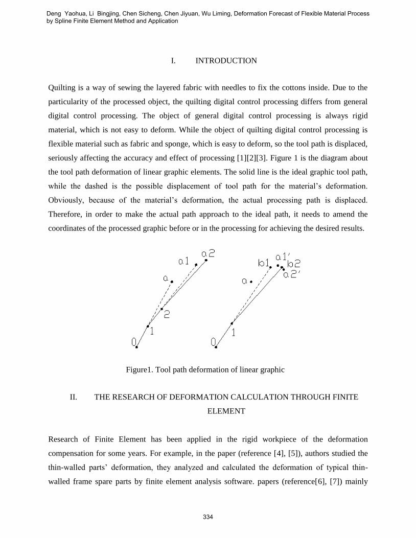
seriously affecting the accuracy and effect of processing [1][2][3]. Figure 1 is the diagram about
the tool path deformation of linear graphic elements. The solid line is the ideal graphic tool path,
while the dashed is the possible displacement of tool path for the material’s deformation.
Obviously, because of the material’s deformation, the actual processing path is displaced.
Therefore, in order to make the actual path approach to the ideal path, it needs to amend the
coordinates of the processed graphic before or in the processing for achieving the desired results.
II. THE RESEARCH OF DEFORMATION CALCULATION THROUGH FINITE
ELEMENT
Research of Finite Element has been applied in the rigid workpiece of the deformation
compensation for some years. For example, in the paper (reference [4], [5]), authors studied the
thin-walled parts’ deformation, they analyzed and calculated the deformation of typical thin-
walled frame spare parts by finite element analysis software. papers (reference[6], [7]) mainly
Figure1. Tool path deformation of linear graphic
elements deformation
Deng Yaohua, Li Bingjing, Chen Sicheng, Chen Jiyuan, Wu Liming, Deformation Forecast of Flexible Material Process by Spline Finite Element Method and Application
334
studied the deformation and impact factors of the digital control processed the structural parts of
the aircraft, according to the analysis of the influence to the aircraft’s structural parts of digital
control processing from the cutting force to deformation, residual stress to processing
deformation and fixture and layout, the condition of workpiece’s processing deformation can be
got by the simulation processing, so as to compensate digitally to the deformation to reach the
requirement of accuracy. As for flexible materials, the current study is just to simulate the
deformation of flexible materials. There are also some scholars studying the measurement of the
tool path deformation and compensation. But they did not combine the model prediction together
with the compensation method of deformation. Zhang Yitong[8]simulated the square fabric
stretching to overhang and buckle on the round table with the use of finite element method basing
on the meso-mechanics model of fabric, and carefully observed the model. Later they calculated
the buckling deformation, and did the experiment of the square fabric’s overhanging and bucking
at the same time. J.G.Teng [9] used the finite volume method to analyze the overhanging
deformation of the fabric, the method is originally used for hydrodynamics calculation, and later
for the deformation of the fabric by the researchers. In the paper [10], researchers predict the
deformation according to the fabric’s border and the compression to adaptively choose the finite
element method, experiment demonstrates that the result of finite element equation suggested by
the researchers is more effective than any other methods in the past. Reference [11-16] studied
the modeling of flexible material deformation by intelligent methods such as neural networks,
regression analysis. These methods have obtained better simulation effect.
On the basis of the researches above, to study the dynamic deformation of soft material and the
deformation in the processing by finite element theoretically works. In this essay, the spline finite
element method has beenused, which is to take the flat fabric as anisotropic material to analyze
the deformation of the flat fabric composed of yarns, then distributed sensors are utilized to
measure the pressure stressed on soft material, combining above two steps, it can calculate
deformation of the soft materials while processing.
III. THE MODEL OF DEFORMATION
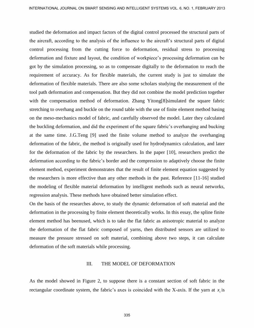
As the model showed in Figure 2, to suppose there is a constant section of soft fabric in the
rectangular coordinate system, the fabric’s axes is coincided with the X-axis. If the yarn at ix is
INTERNATIONAL JOURNAL ON SMART SENSING AND INTELLIGENT SYSTEMS VOL. 6, NO. 1, FEBRUARY 2013
335
differential settlement iy , then the fabric’s deflection curve can be expressed by )(xS i
(i=0,1,2,……,m).
For the special object, the fabric which is regularly composed of yarns, the spline finite element
method taking advantages of the spline function and finite element method, is suitable for the
analysis of the special material, fabrics’ particular deformation. The spline finite element method
is based on the Variational Principle and cubic B-spline function [9]. The displacement function
is composed of linear product of cubic B-spline function, and both directions use the cubic B-
spline function. The overall stiffness equation is established by the variational principle. This
method can be applied to various structural analyses in the regular area.
Suppose in the interval [a,b], there is a partition : 0 1 2 1..... m ma bx x x x x , and the
function )(xS i in [a,b] is named as cubic spline function( )(3 xs ) if it satisfies the following
conditions [18]:
①In each subinterval ],[ 1 ii xx )(3 xs is a cubic polynomial. ②In the whole interval [a b], )(3 xs
is a second order continuous differentiable function, that is , at the point ix (the node of )(3 xs ),
it satisfies )0()0()(
3
)(
3 i
k
i
k
xsxs ( 2,1,0k ). ③When an ordered sequence iy is given, if )(3 xs
satisfies the condition again: ii yxs )(3 ,then )(3 xs is called as an interpolation cubic spline
function.If is the deflection of the yarn, xM is the flexural moment and E is bending stiffness.
With the use of Fig.2, to simulate single yarn for analysis of the cubic spline finite point. The
relationship between its flexural moment and deflection is as following:
Figure 2. Cross section of the fabric
Deng Yaohua, Li Bingjing, Chen Sicheng, Chen Jiyuan, Wu Liming, Deformation Forecast of Flexible Material Process by Spline Finite Element Method and Application
336
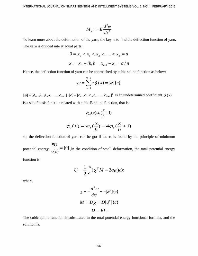
2
2x
dM E
dx
To learn more about the deformation of the yarn, the key is to find the deflection function of yarn.
The yarn is divided into N equal parts:
axxxx n.....0 210
naxxhihxx iii /, 10
Hence, the deflection function of yarn can be approached by cubic spline function as below:
1
1
( ) [ ]{ }N
i i
i
c x c
],.......,,,[][ 11101 N , T
Ncccccc ],.......,,,[][ 11101 is an undetermined coefficient. )(xi
is a set of basis function related with cubic B-spline function, that is:
1 3( ) ( 1)x
xh
)1(4)()( 330h
x
h
xx
so, the deflection function of yarn can be got if the ic is found by the principle of minimum
potential energy: }0{}{c
U,In the condition of small deformation, the total potential energy
function is:
dxqMUa
T )2(2
1
0
where,
}]{[2
2
cdx
d
[ ]{ }M D D c
EID .
The cubic spline function is substituted in the total potential energy functional formula, and the
solution is:
INTERNATIONAL JOURNAL ON SMART SENSING AND INTELLIGENT SYSTEMS VOL. 6, NO. 1, FEBRUARY 2013
337
1{ } [ ]{ } { } { }
2
T TU c G c c k
dxDGa
T ][][][0
0{ } [ ]
aTk qdx
as EI is a constant, then it can be got from the formula above:
dxADAGa
T
xx ][][,][0
and the changed total potential energy functional formula is substituted in the minimum potential
energy formula, and the result is:
[ ]{ } { }G c k
It is the stiffness equation of yarn, [G] stands for the stiffness matrix {k} is the load matrix, so:
{ } { }{ }
[ ] * x
k kc
G EI A
It can be seen that to analyze the fabric, especially the single yarn by cubic spline function is
feasible. What is more, approaching the result in the use of spline is effective and with little
calculation. Compared with the finite element method, it is more simple and convenient.
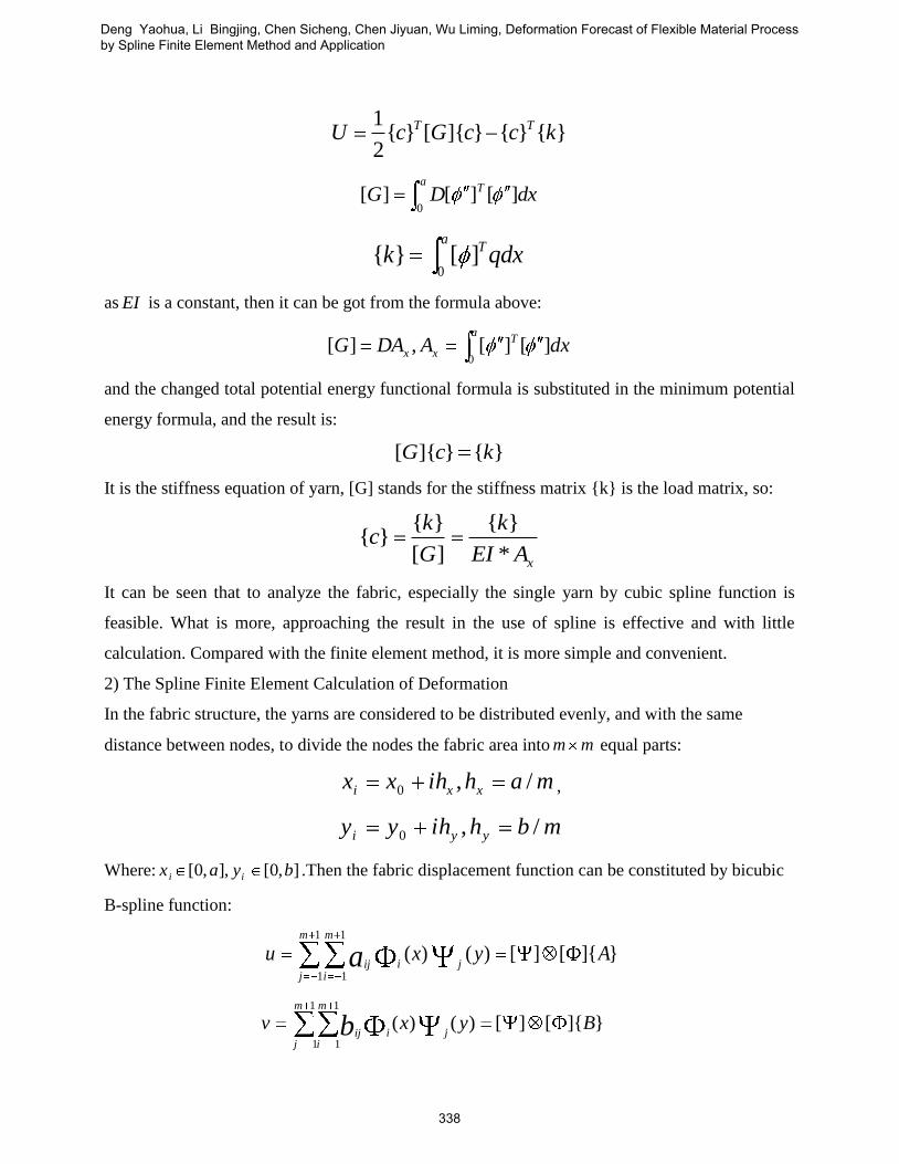
2) The Spline Finite Element Calculation of Deformation
In the fabric structure, the yarns are considered to be distributed evenly, and with the same
distance between nodes, to divide the nodes the fabric area into mm equal parts:
mahihxx xxi /,0 ,
mbhihyy yyi /,0
Where: ],0[],,0[ byax ii .Then the fabric displacement function can be constituted by bicubic
B-spline function:
}]{[][)()(1
1
1
1
Ayxuji
m
j
m
iija
}]{[][)()(1
1
1
1
Byxvji
m
j
m
iijb
Deng Yaohua, Li Bingjing, Chen Sicheng, Chen Jiyuan, Wu Liming, Deformation Forecast of Flexible Material Process by Spline Finite Element Method and Application
338
}]{[][)()(1
1
1
1
Cyxwji
m
j
m
iijc
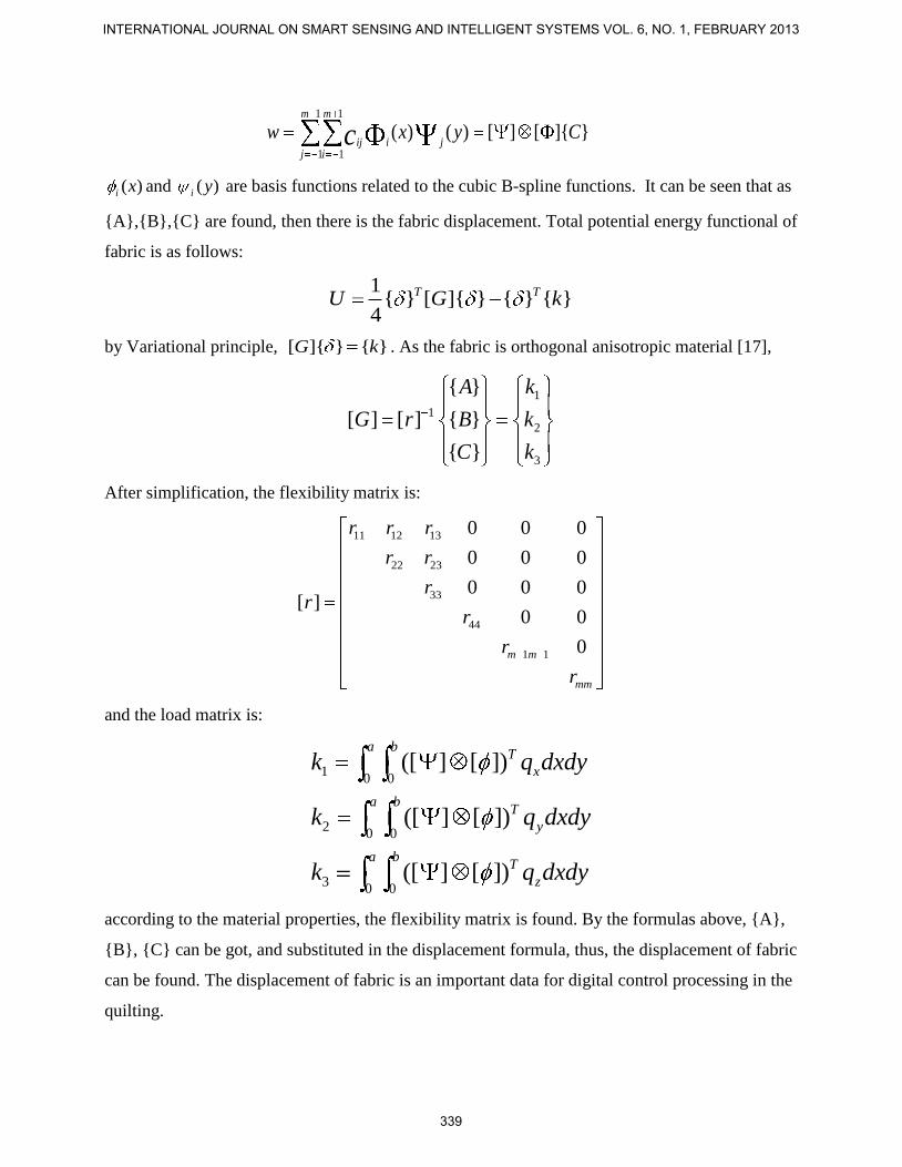
)(xi and )(yi are basis functions related to the cubic B-spline functions. It can be seen that as
{A},{B},{C} are found, then there is the fabric displacement. Total potential energy functional of
fabric is as follows:
1{ } [ ]{ } { } { }
4
T TU G k
by Variational principle, [ ]{ } { }G k . As the fabric is orthogonal anisotropic material [17],
1
1
2
3
{ }
[ ] [ ] { }
{ }
A k
G r B k
C k
After simplification, the flexibility matrix is:
11 12 13
22 23
33
44
1 1
0 0 0
0 0 0
0 0 0[ ]
0 0
0m m
mm
r r r
r r
rr
r
r
r
and the load matrix is:
10 0
20 0
30 0
([ ] [ ])
([ ] [ ])
([ ] [ ])
a bT
x
a bT
y
a bT
z
k q dxdy
k q dxdy
k q dxdy
according to the material properties, the flexibility matrix is found. By the formulas above, {A},
{B}, {C} can be got, and substituted in the displacement formula, thus, the displacement of fabric
can be found. The displacement of fabric is an important data for digital control processing in the
quilting.
INTERNATIONAL JOURNAL ON SMART SENSING AND INTELLIGENT SYSTEMS VOL. 6, NO. 1, FEBRUARY 2013
339
IV. THE SIMULATION OF DEFORMATION
To take deformation of rectangular flexible material as example, the composition of the material
is polyurethane foam. The modulus of elasticity E = 0.3078MPa, Poisson coefficient μ = 0.3, the
length of a is 160mm, width b is 90mm, thickness h is 5mm.Figure3 shows the stress-strain
characteristic curve. Choose the rectangle material loading point load the points on the diagonal
[19] [20], concentrated load is 10 N. Figure 4 shows deformation mechanics simulation and the
theoretical results. Bending displacement distribution curve of a, b axis is respectively for the
length, width of flexible material. On the basis above, to measuring six points on the surface of
flexible workpiece surface of Figure 4(a). Digital pressure gauge with micrometer is used to
measure point by point. Table 1 shows results of comparison between theoretical value and
measured value.
I. THE ANALYSIS OF PROCESSING TESTING AND RESULTS
To apply above method to quilting processing, the quilting machine and quilting processing
diagram are shown in Figure 5, Figure 6 and Figure 7. Figure 5 shows the Quilting machine, it is
3-axis CNC machine tools. Figure 6 and Figure 7 shows the process of quilting of one kind of
quilting pattern [21] [22].
a. Line deformation compensation testing
The embossing mold composed of linear graphic elements is chosen to process, the processing
thickness is 5mm, the largest deformation occurs at the point of the punch block moving to the
lowest.
Deng Yaohua, Li Bingjing, Chen Sicheng, Chen Jiyuan, Wu Liming, Deformation Forecast of Flexible Material Process by Spline Finite Element Method and Application
340

(a) Stress and strain test devices
(b) The stress-strain characteristic curve
Figure 3. Material stress and strain characteristic curve
Deformation displacement vector Deflection of the distribution curve
(a) 120, 60x y
INTERNATIONAL JOURNAL ON SMART SENSING AND INTELLIGENT SYSTEMS VOL. 6, NO. 1, FEBRUARY 2013
341

Stress distribution cloud diagram Deflection of the distribution curve
(b) 40, 70l k
Figure 4. Deformation displacement vector and displacement distribution diagram
From table 1, it can calculate results of the average of the relative deviation is only 7.35%.
Table1: Comparison between theoretical value and measured value of deformation of
flexible workpiece
Serial
number
X-YPlane
coordinates(mm)
Theoretical
value(mm) measured(mm) Relative deviation(%)
1 (120,60) 4.35 4.08 6.56
2 (40,70) 4.36 4.07 7.12
3 (40,20) 3.68 3.44 6.78
4 (120,20) 3.68 3.42 7.56
5 (80,45) 7.18 6.65 7.89
6 (160,45) 4.70 4.34 8.21
Average 7.35
Deng Yaohua, Li Bingjing, Chen Sicheng, Chen Jiyuan, Wu Liming, Deformation Forecast of Flexible Material Process by Spline Finite Element Method and Application
342
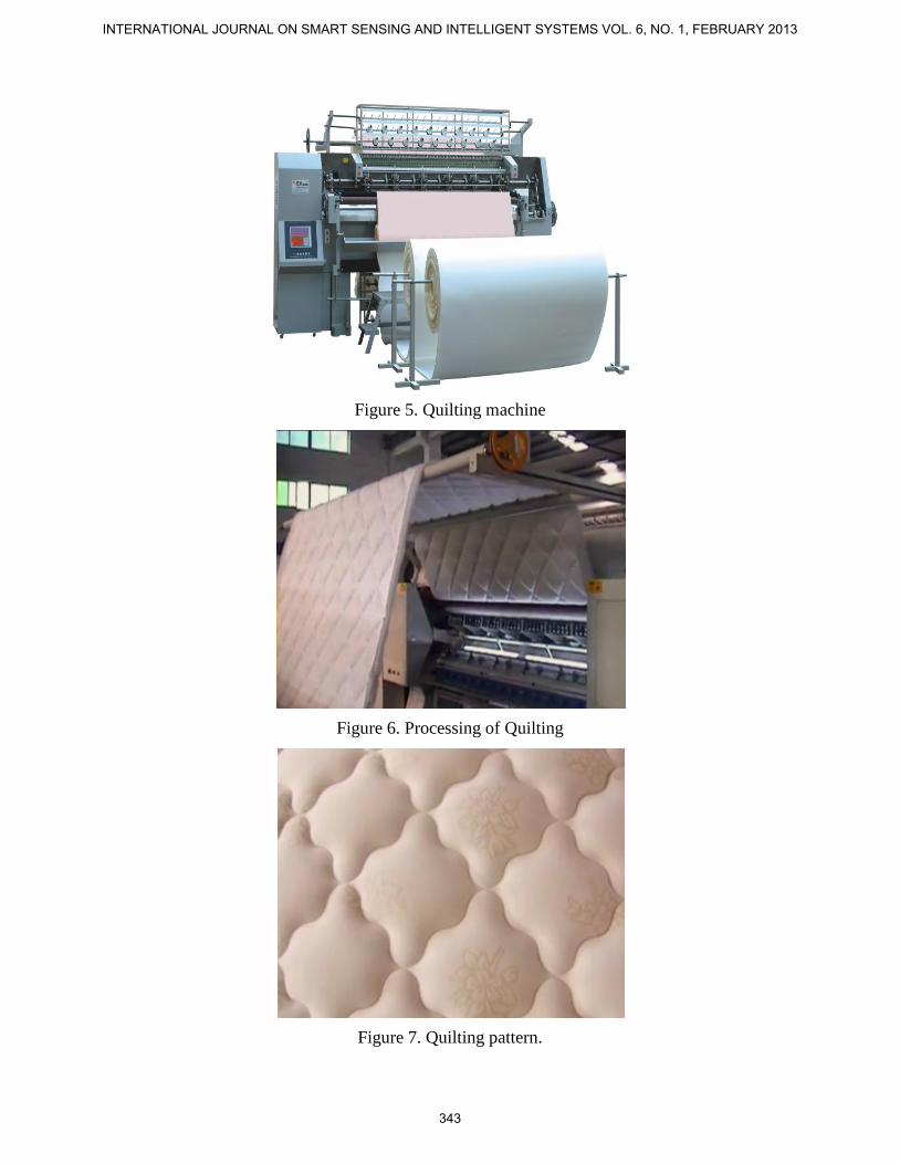
Figure 5. Quilting machine
Figure 6. Processing of Quilting
Figure 7. Quilting pattern.
INTERNATIONAL JOURNAL ON SMART SENSING AND INTELLIGENT SYSTEMS VOL. 6, NO. 1, FEBRUARY 2013
343
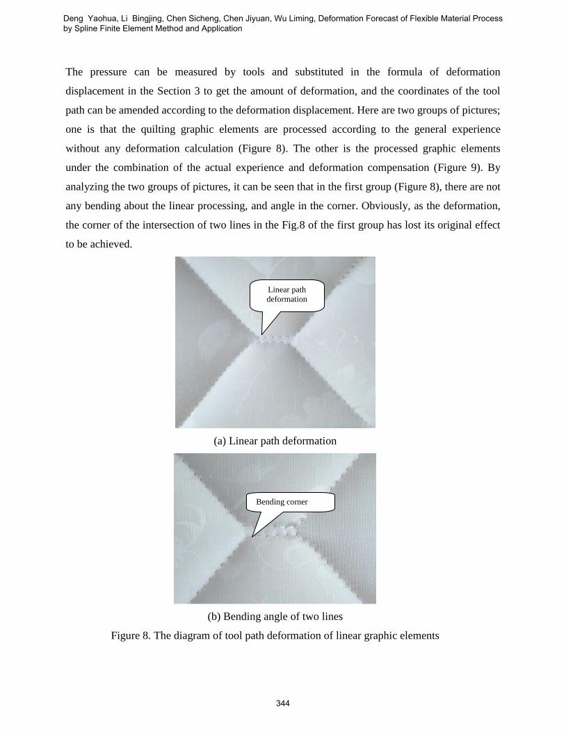
The pressure can be measured by tools and substituted in the formula of deformation
displacement in the Section 3 to get the amount of deformation, and the coordinates of the tool
path can be amended according to the deformation displacement. Here are two groups of pictures;
one is that the quilting graphic elements are processed according to the general experience
without any deformation calculation (Figure 8). The other is the processed graphic elements
under the combination of the actual experience and deformation compensation (Figure 9). By
analyzing the two groups of pictures, it can be seen that in the first group (Figure 8), there are not
any bending about the linear processing, and angle in the corner. Obviously, as the deformation,
the corner of the intersection of two lines in the Fig.8 of the first group has lost its original effect
to be achieved.
(a) Linear path deformation
(b) Bending angle of two lines
Figure 8. The diagram of tool path deformation of linear graphic elements
Linear path
deformation
Bending corner
Deng Yaohua, Li Bingjing, Chen Sicheng, Chen Jiyuan, Wu Liming, Deformation Forecast of Flexible Material Process by Spline Finite Element Method and Application
344
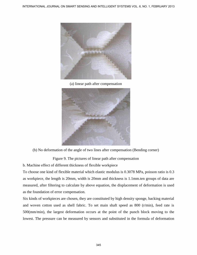
(a) linear path after compensation
(b) No deformation of the angle of two lines after compensation (Bending corner)
Figure 9. The pictures of linear path after compensation
b. Machine effect of different thickness of flexible workpiece
To choose one kind of flexible material which elastic modulus is 0.3078 MPa, poisson ratio is 0.3
as workpiece, the length is 20mm, width is 20mm and thickness is 1.1mm.ten groups of data are
measured, after filtering to calculate by above equation, the displacement of deformation is used
as the foundation of error compensation.
Six kinds of workpieces are chosen, they are constituted by high density sponge, backing material
and woven cotton used as shell fabric. To set main shaft speed as 800 (r/min), feed rate is
500(mm/min), the largest deformation occurs at the point of the punch block moving to the
lowest. The pressure can be measured by sensors and substituted in the formula of deformation
INTERNATIONAL JOURNAL ON SMART SENSING AND INTELLIGENT SYSTEMS VOL. 6, NO. 1, FEBRUARY 2013
345
displacement in the Section 3 to get the amount of deformation, and the coordinates of the tool
path can be amended according to the deformation displacement.
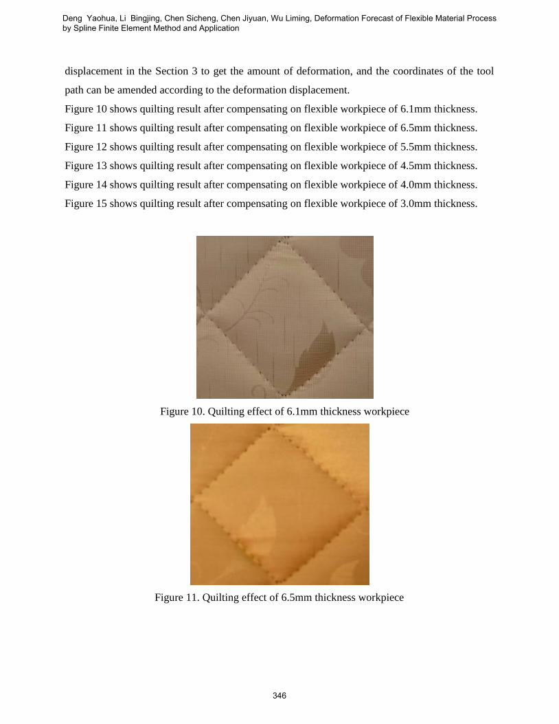
Figure 10 shows quilting result after compensating on flexible workpiece of 6.1mm thickness.
Figure 11 shows quilting result after compensating on flexible workpiece of 6.5mm thickness.
Figure 12 shows quilting result after compensating on flexible workpiece of 5.5mm thickness.
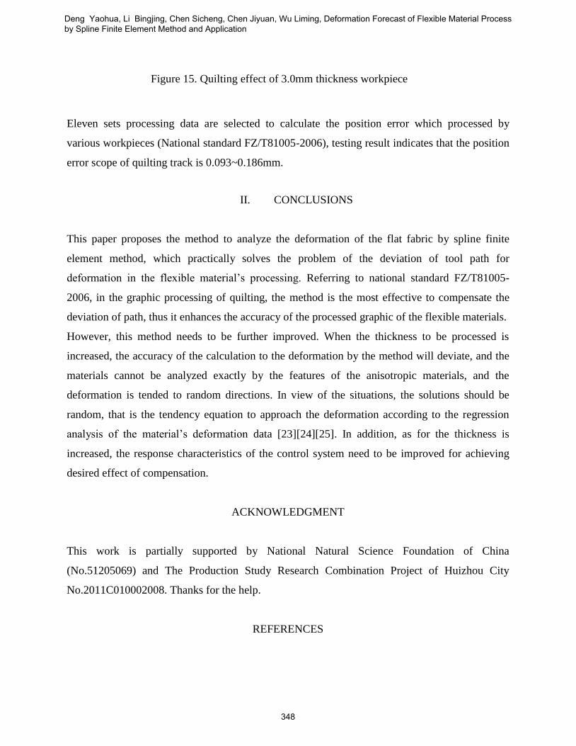
Figure 13 shows quilting result after compensating on flexible workpiece of 4.5mm thickness.
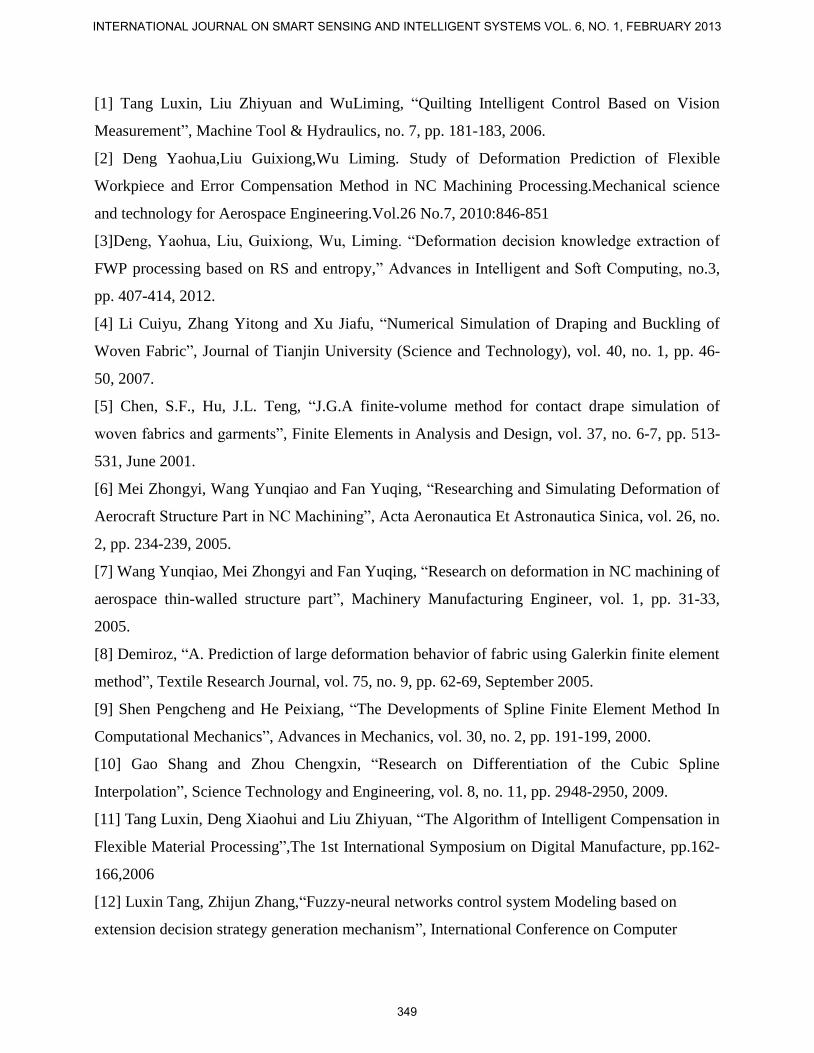
Figure 14 shows quilting result after compensating on flexible workpiece of 4.0mm thickness.
Figure 15 shows quilting result after compensating on flexible workpiece of 3.0mm thickness.
Figure 10. Quilting effect of 6.1mm thickness workpiece
Figure 11. Quilting effect of 6.5mm thickness workpiece
Deng Yaohua, Li Bingjing, Chen Sicheng, Chen Jiyuan, Wu Liming, Deformation Forecast of Flexible Material Process by Spline Finite Element Method and Application
346
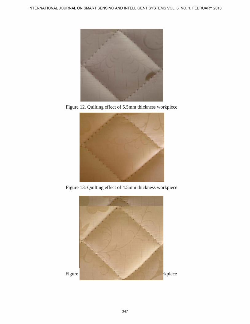
Figure 12. Quilting effect of 5.5mm thickness workpiece
Figure 13. Quilting effect of 4.5mm thickness workpiece
Figure 14. Quilting effect of 4.0mm thickness workpiece
INTERNATIONAL JOURNAL ON SMART SENSING AND INTELLIGENT SYSTEMS VOL. 6, NO. 1, FEBRUARY 2013
347
Eleven sets processing data are selected to calculate the position error which processed by
various workpieces (National standard FZ/T81005-2006), testing result indicates that the position
error scope of quilting track is 0.093~0.186mm.
II. CONCLUSIONS
This paper proposes the method to analyze the deformation of the flat fabric by spline finite
element method, which practically solves the problem of the deviation of tool path for
deformation in the flexible material’s processing. Referring to national standard FZ/T81005-
2006, in the graphic processing of quilting, the method is the most effective to compensate the
deviation of path, thus it enhances the accuracy of the processed graphic of the flexible materials.
However, this method needs to be further improved. When the thickness to be processed is
increased, the accuracy of the calculation to the deformation by the method will deviate, and the
materials cannot be analyzed exactly by the features of the anisotropic materials, and the
deformation is tended to random directions. In view of the situations, the solutions should be
random, that is the tendency equation to approach the deformation according to the regression
analysis of the material’s deformation data [23][24][25]. In addition, as for the thickness is
increased, the response characteristics of the control system need to be improved for achieving
desired effect of compensation.
ACKNOWLEDGMENT
This work is partially supported by National Natural Science Foundation of China
(No.51205069) and The Production Study Research Combination Project of Huizhou City
No.2011C010002008. Thanks for the help.
REFERENCES
Figure 15. Quilting effect of 3.0mm thickness workpiece
Deng Yaohua, Li Bingjing, Chen Sicheng, Chen Jiyuan, Wu Liming, Deformation Forecast of Flexible Material Process by Spline Finite Element Method and Application
348
[1] Tang Luxin, Liu Zhiyuan and WuLiming, “Quilting Intelligent Control Based on Vision
Measurement”, Machine Tool & Hydraulics, no. 7, pp. 181-183, 2006.
[2] Deng Yaohua,Liu Guixiong,Wu Liming. Study of Deformation Prediction of Flexible
Workpiece and Error Compensation Method in NC Machining Processing.Mechanical science
and technology for Aerospace Engineering.Vol.26 No.7, 2010:846-851
[3]Deng, Yaohua, Liu, Guixiong, Wu, Liming. “Deformation decision knowledge extraction of
FWP processing based on RS and entropy,” Advances in Intelligent and Soft Computing, no.3,
pp. 407-414, 2012.
[4] Li Cuiyu, Zhang Yitong and Xu Jiafu, “Numerical Simulation of Draping and Buckling of
Woven Fabric”, Journal of Tianjin University (Science and Technology), vol. 40, no. 1, pp. 46-
50, 2007.
[5] Chen, S.F., Hu, J.L. Teng, “J.G.A finite-volume method for contact drape simulation of
woven fabrics and garments”, Finite Elements in Analysis and Design, vol. 37, no. 6-7, pp. 513-
531, June 2001.
[6] Mei Zhongyi, Wang Yunqiao and Fan Yuqing, “Researching and Simulating Deformation of
Aerocraft Structure Part in NC Machining”, Acta Aeronautica Et Astronautica Sinica, vol. 26, no.
2, pp. 234-239, 2005.
[7] Wang Yunqiao, Mei Zhongyi and Fan Yuqing, “Research on deformation in NC machining of
aerospace thin-walled structure part”, Machinery Manufacturing Engineer, vol. 1, pp. 31-33,
2005.
[8] Demiroz, “A. Prediction of large deformation behavior of fabric using Galerkin finite element
method”, Textile Research Journal, vol. 75, no. 9, pp. 62-69, September 2005.
[9] Shen Pengcheng and He Peixiang, “The Developments of Spline Finite Element Method In
Computational Mechanics”, Advances in Mechanics, vol. 30, no. 2, pp. 191-199, 2000.
[10] Gao Shang and Zhou Chengxin, “Research on Differentiation of the Cubic Spline
Interpolation”, Science Technology and Engineering, vol. 8, no. 11, pp. 2948-2950, 2009.
[11] Tang Luxin, Deng Xiaohui and Liu Zhiyuan, “The Algorithm of Intelligent Compensation in
Flexible Material Processing”,The 1st International Symposium on Digital Manufacture, pp.162-
166,2006
[12] Luxin Tang, Zhijun Zhang,“Fuzzy-neural networks control system Modeling based on
extension decision strategy generation mechanism”, International Conference on Computer
INTERNATIONAL JOURNAL ON SMART SENSING AND INTELLIGENT SYSTEMS VOL. 6, NO. 1, FEBRUARY 2013
349
Science and Software Engineering,pp.1172-1175,2008.
[13]Deng Yaohua Liu Guixiong, “ATS-FNN-Based Modeling and Simulation for Compensation
Prediction of FWP Machining Deformation”, Journal of South China University of Technology
(Natural Science Edition), vol.40, no. 3, pp.146-151, 2012.
[14] Deng Yaohua,Han wei, “Regression Calculation Model of Flexible Material Processing
Deformation based on Distributed Sensors Measurement” , Advances in Information Sciences
and Service Sciences, vol. 3, no.3, pp. 208-212, 2011.
[15] Yaohua Deng, Guixiong Liu, Qiaofu Liao, “Research of FWP Process Deformation
Compensation Forecasting on the Basis of TS-FNN” , Advanced Materials Research, vol. 295-
297, pp. 2430-2437, 2011.
[16]Deng Yaohua, Liu Guixiong,Wu Liming, “The Research on the Deformation of Tool Path
of Flexible Workpiece Based on Prediction Model ” , Computer and Automation Engineering,
pp.501-505, 2010.
[17] Li Yan. “A Study of Anisotropic Mechanical Proterties of Apparel Woven Fabrics”, Journal
of Textile Research, vol. 24, no. 2, pp. 118-120, 2003.
[18] Yu Shijia and Yan Yuxiu, “Correlation Research of Fabric Elasticity and Jeans Pattern
Design”, Journal of Zhejiang Institute of Science and Technology, vol. 26, no. 1, pp. 57-60, 2009.
[19] Wu Kai, He Ning,Liao Wenhe, “Selection of Cutting Parameters in High Speed Milling of
Thin-W ailed Structure Components Based on the Machining Errors Control,” MECHANICAL
SCIENCE AND TECHNOLOGY, vol. 24, no. 7, pp. 788-791, 2005.
[20] John M.Fines, Arvin Agah, “Machine tool positioning error compensation using artificial
neural networks,” Engineering Applications of Artificial Intelligence, vol. 21, pp. 1013-1026,
2008.
[21] Yongjin Kwon, Gary W. Fischer, “Fuzzy Neuron Adaptive Modeling to Predict Surface
Roughness under Process Variations in CNC Turning,” Journal of Manufacturing Systems, vol.
21, no. 6, pp. 440-450, 2002.
[22] Tang Luxin,Yao Huan and Zhang Zhijun, “Research of Relief Pattern Design Based on
Improved Genetic Algorithm Intelligent Information Technology Application Workshops,”
IITAW '08, pp.459 -462, 2008.
[23] MIAO DuoQian, “A new method of discretization of continuous attributes in rough sets,”
Acta Automatica Sinica, vol. 27, pp. 296-302, 2001.
Deng Yaohua, Li Bingjing, Chen Sicheng, Chen Jiyuan, Wu Liming, Deformation Forecast of Flexible Material Process by Spline Finite Element Method and Application
350

[24] Deng, Yaohua, Liu, Guixiong, Wu, Liming. “Deformation decision knowledge extraction
of FWP processing based on RS and entropy,” Advances in Intelligent and Soft Computing,
no.3, pp. 407-414, 2012.
[25] Feng Jiang, Yuefei Sui, Cungen Cao, “An information entropy-based approach to outlier
detection in rough sets,” Expert Systems with Applications, vol. 37, pp. 6338-6344, 2010.
INTERNATIONAL JOURNAL ON SMART SENSING AND INTELLIGENT SYSTEMS VOL. 6, NO. 1, FEBRUARY 2013
351


![Block Sparse Compressed Sensing of Electroencephalogram ... · derivative of Gaussian function), a linear spline, a cubic spline, and a linear B spline and cubic B-spline. In [7],](https://img.pdfslide.us/doc/110x75/5f870bc34c82e452c7534b24/block-sparse-compressed-sensing-of-electroencephalogram-derivative-of-gaussian.jpg)