Embed Size (px)
Citation preview
GUIDE TO PUMPS, AND RELATED HYDRAULICS TECHNICAL REFERENCE
MANUAL A “MUST READ” FOR ANY IRRIGATION
PROFESSIONAL
By Robert Beausoleil
11 LOCATIONS TO SERVE YOU
1120 Goffle Road 64 S. Jefferson Road Hawthorne NJ 07506 Whippany NJ 07981 973-423-0222 973-386-9076
852 E. Main Street Norristown PA 19401
1000 Airport Road Lakewood, NJ 08701 732-363-5034 610-277-9764
314 West Basin Road 223 Blackwood/Barnsboro Rd New Castle DE 19720 Sewell NJ 08080 302-328-3326 856-228-6070
8207B Rear Clover Leaf Drive Millersville MD 21108 410-761-9455
4120 Pepsi Place Chantilly VA 20151 703-263-1272
4910 Quality Drive Fredericksburg VA 22408 540-891-8100
38373 Sussex Highway, Suite 1 Delmar DE 19940302-846-3118
131 Lloyd Street Allentown, PA 18109 610-231-2009
2
INDEX
Pump Types and Must Know Formula ………….. pg. 3 Sizing a Pump For Sucking Out of a Pond.…….... pg. 4 Recommended Suction Pump Installation……….. pg. 5-6 Booster Pump Installation ……………………….. pg. 7-8 Well Test to Determine How Much Water Is Produced from an Existing Pumping System… pg. 9-10 General Purpose Centrifugal Pump Curve ……… pg. 11 Self Priming Centrifugal Pump Curve …………... pg.12-13 Self Priming Centrifugal Multi-stage Pump …… pg. 14 Centrifugal Multi-stage Pump Curve …………….pg. 15 Submersible Pump Curve……………………….. pg. 16 Simer Booster Pump Data Sheet………………… pg. 17 Mascontrol Data Sheet …………………………...pg. 18
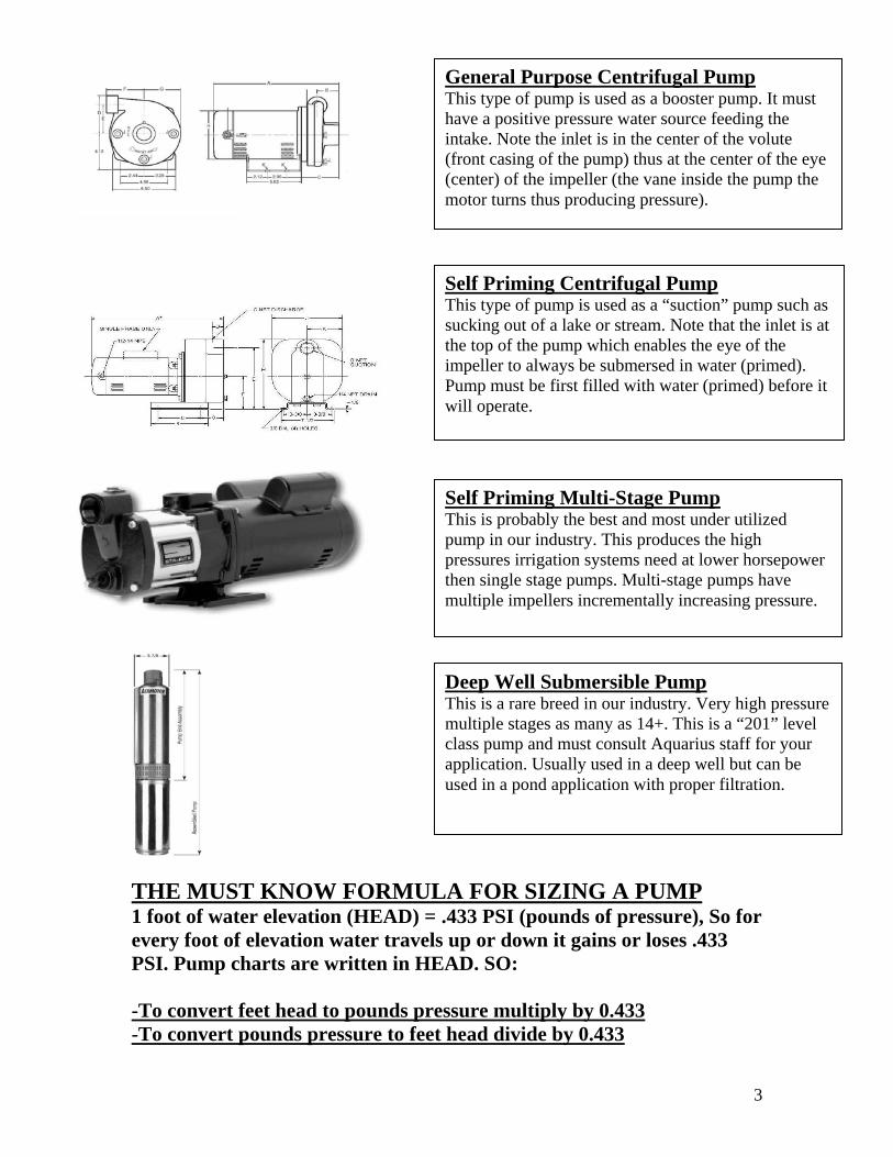
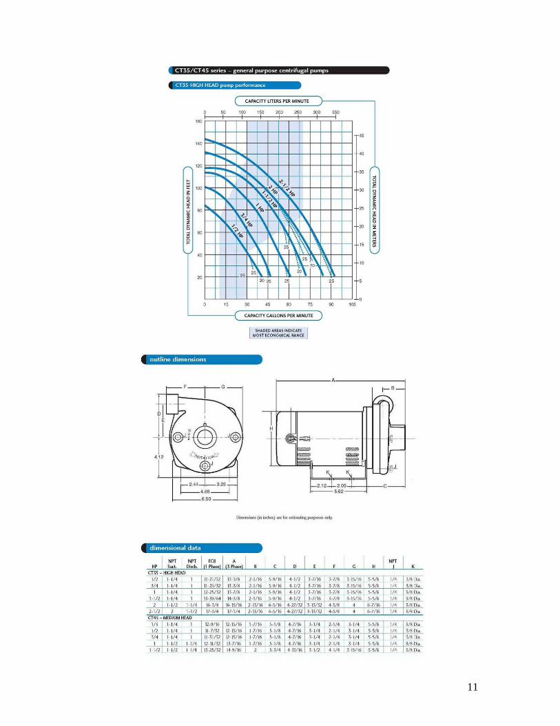
General Purpose Centrifugal Pump This type of pump is used as a booster pump. It must have a positive pressure water source feeding the intake. Note the inlet is in the center of the volute (front casing of the pump) thus at the center of the eye (center) of the impeller (the vane inside the pump the motor turns thus producing pressure).
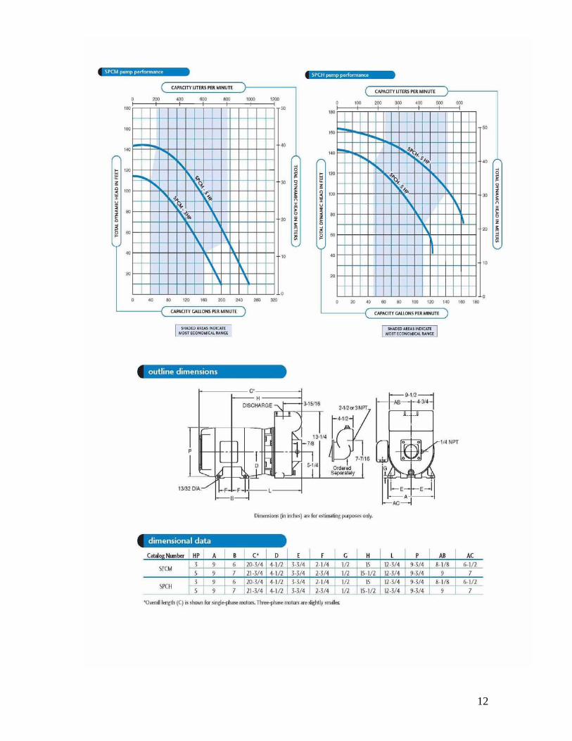
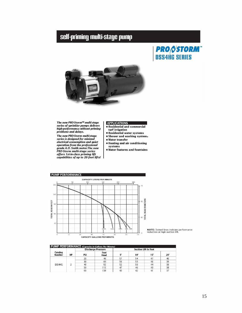
Self Priming Centrifugal Pump This type of pump is used as a “suction” pump such as sucking out of a lake or stream. Note that the inlet is at the top of the pump which enables the eye of the impeller to always be submersed in water (primed). Pump must be first filled with water (primed) before it will operate.
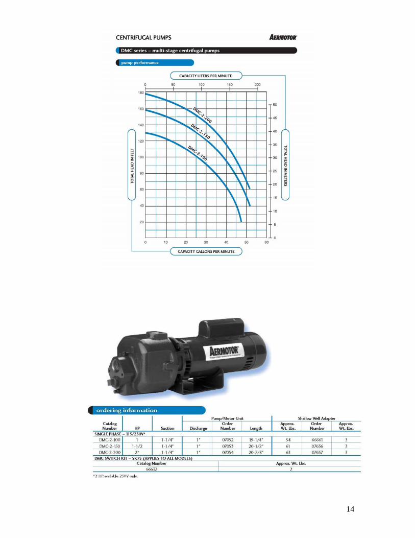
Self Priming Multi-Stage Pump This is probably the best and most under utilized pump in our industry. This produces the high pressures irrigation systems need at lower horsepower then single stage pumps. Multi-stage pumps have multiple impellers incrementally increasing pressure.
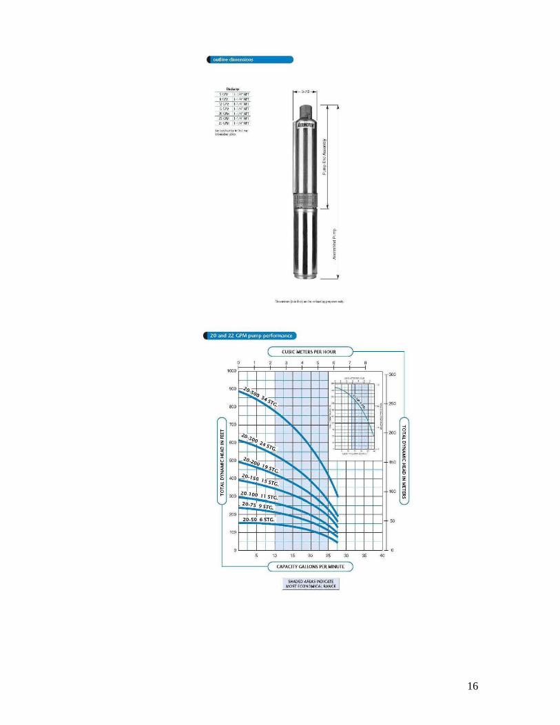
Deep Well Submersible Pump This is a rare breed in our industry. Very high pressure multiple stages as many as 14+. This is a “201” level class pump and must consult Aquarius staff for your application. Usually used in a deep well but can be used in a pond application with proper filtration.
THE MUST KNOW FORMULA FOR SIZING A PUMP 1 foot of water elevation (HEAD) = .433 PSI (pounds of pressure), So for every foot of elevation water travels up or down it gains or loses .433 PSI. Pump charts are written in HEAD. SO: -To convert feet head to pounds pressure multiply by 0.433 -To convert pounds pressure to feet head divide by 0.433
3
4
SIZING A PUMP FOR THE PURPOSE OF RUNNING AN
IRRIGATION SYSTEM SUCKING OUT OF A POND USING A SELF PRIMING CENTRIFUGAL PUMP
1. Design your irrigation system using a piping grid with proper velocities around 5 FPS (feet per second) and minimal pressure loss through the piping grid. 2. Determine friction loss through your system. EXAMPLE: 18 GPM (assumption: there are no elevation changes at this property)
1. Distance from pond to pump is 20’=loss in 1.5” poly pipe = (no need to calculate, very small) 2. Distance from pump to farthest valve is 700’= loss in 1.5” poly pipe = 1.01 per 100 feet* 7=7.07 PSI lost. 3. Loss through 100DV 1” = 5 PSI lost. 4. Distance to first head 100’ with 1.25” poly = 2.13 PSI lost. 5. Heads are 3 GPM spaced 40’ apart.
a. Loss to second head at 15 GPM with 1.25” poly = 2.13 x .4 = .852 PSI lost. b. Loss to third head at 12 GPM with 1” poly = 3.82 x .4=1.52 PSI lost. c. Loss to fourth head at 9 GPM with 1” poly = 2.24 x .4=.896 PSI lost. (If you stay with 1” poly you do not have to do any more calculations)
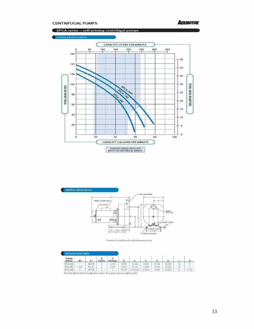
3. Add up all your friction loss calculations: 7.07+5+2.13+.852+1.52+..896=17.468 pounds per square inch will be lost through our system design. 4. Now let’s change our loss to feet of head: 17.468 / .433=40.34 feet of head. 5. Remember: we assumed that there were no elevation changes within our piping grid. If there were we would have to calculate head (elevation) at .433 per foot of elevation and add this to our total desired pump output. But for realistic sake we must make the pump higher then the pond to stay dry. So we will say the pump is 16 feet above the pond. 6. For the sprinkler heads to operate we need at least 35 PSI at the sprinkler 7. Now let’s add up our minimum total requirements in terms of head needed at 18 GPM to operate this system: 40.34 (pipe grid) +16 (elevation above pond) +80.83 (PSI to run heads 35 / .433) =137.17 feet of head or 59.39 PSI (137.17 x .433) 8. Time to look at pump charts. A. How about Aeromotor SPCA series on Page 13?
B. Maximum feet of head out of a 2HP @ 20 GPM is 120, so this pump will not work.
C. How about the 2 stage centrifugal DMC series Page 14? D. The DMC2-150 will give us around 140 feet of head and it is only a 1.5HP pump. This one will work for your needs.
* Typically we sell way too many high horsepower pumps to get the desired pressure when all that is needed are lower horsepower dual stage higher pressure, “center of curve pumps”.
5
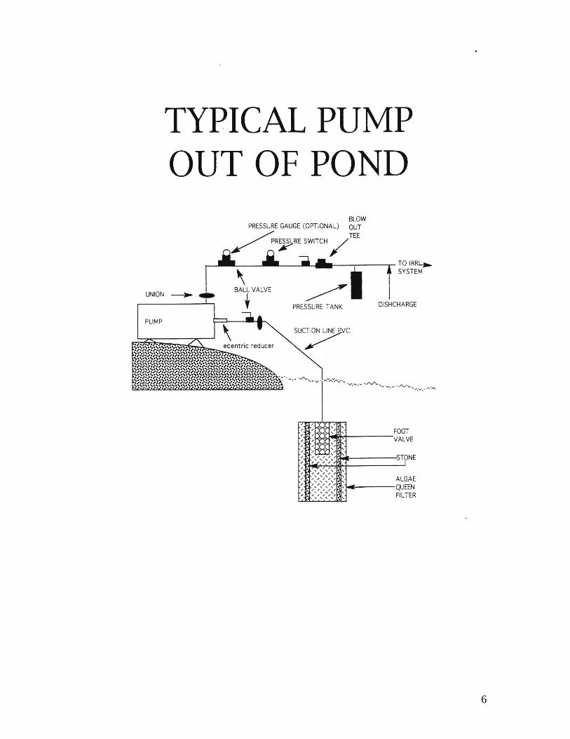
AQUARIUS RECOMMENDED SUCTION PUMP
INSTALLATION PROCEDURE
Note: Only a self priming pump should be used. 1. Design your irrigation system and choose the proper pump to do the job. 2. Buy a cheap dog house or build an enclosure so the pump will stay dry and it will be accessible for repair and winterization. 3. Find an old car tire and rim that holds air. Buy an “Algae Queen” from Aquarius so you can bolt it to the rim through the lug nut holes. Assemble the Algae Queen with a foot valve (check valve with a screen) in the center and pea gravel around the outer and inner screens. 4. Attach a suction line to the unit and float it in the pond and secure the float to the bottom with an anchor or secure it to the shore. A suction line should always rise to a pump, air must travel out. Under no circumstances should a suction line ever undulate up and down, trapping air in the high spots. 5. The suction line should be removed after blowing out the lines. 6. Install the sprinkler system main to the discharge side of the pump and your plumbing hookup is done. Remember to install a blow-out valve for winterization. 7. Your pump is high voltage so it will need to be powered by household current and started by a pump relay which will be activated by the irrigation controller. We recommend that you have a licensed electrician hook up all the electrical service to the pump. Include this cost in your job. 8. All that is left is to wire up the pump start relay and run your system. 9. As an option a Mascontrol pump controller should be used as a quality option. Benefits include: Always pressurized main, no pump start relay, no long wire run for the relay, no burnt-out pumps and melted suction lines from a pump that was run dry from a loss of prime. THIS IS THE BEST KEPT SECERT IN OUR INDUSTRY.
6
7
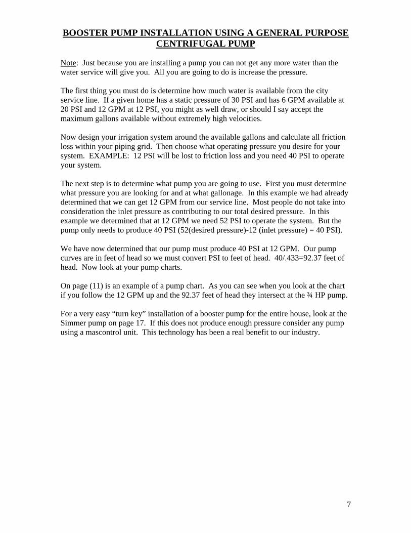
BOOSTER PUMP INSTALLATION USING A GENERAL PURPOSE CENTRIFUGAL PUMP
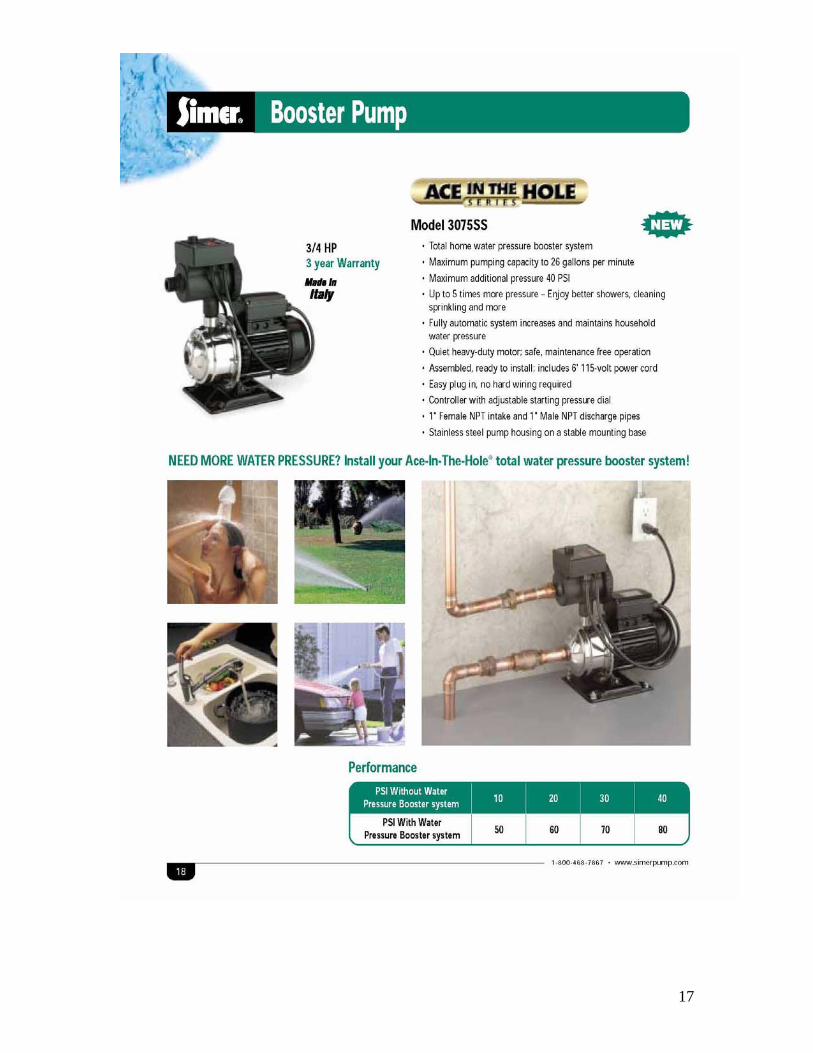
Note: Just because you are installing a pump you can not get any more water than the water service will give you. All you are going to do is increase the pressure. The first thing you must do is determine how much water is available from the city service line. If a given home has a static pressure of 30 PSI and has 6 GPM available at 20 PSI and 12 GPM at 12 PSI, you might as well draw, or should I say accept the maximum gallons available without extremely high velocities. Now design your irrigation system around the available gallons and calculate all friction loss within your piping grid. Then choose what operating pressure you desire for your system. EXAMPLE: 12 PSI will be lost to friction loss and you need 40 PSI to operate your system. The next step is to determine what pump you are going to use. First you must determine what pressure you are looking for and at what gallonage. In this example we had already determined that we can get 12 GPM from our service line. Most people do not take into consideration the inlet pressure as contributing to our total desired pressure. In this example we determined that at 12 GPM we need 52 PSI to operate the system. But the pump only needs to produce 40 PSI (52(desired pressure)-12 (inlet pressure) = 40 PSI). We have now determined that our pump must produce 40 PSI at 12 GPM. Our pump curves are in feet of head so we must convert PSI to feet of head. 40/.433=92.37 feet of head. Now look at your pump charts. On page (11) is an example of a pump chart. As you can see when you look at the chart if you follow the 12 GPM up and the 92.37 feet of head they intersect at the ¾ HP pump. For a very easy “turn key” installation of a booster pump for the entire house, look at the Simmer pump on page 17. If this does not produce enough pressure consider any pump using a mascontrol unit. This technology has been a real benefit to our industry.
8
9
THE ONLY REAL WAY TO DETERMINE HOW MUCH WATER IS PRODUCED BY A PUMPING SYSTEM THAT YOU DID NOT
DESIGN
Thought process: you come upon an existing pumping system typically a deep well pump installation where the home does not have city water. Many factors determine what this system will produce such as the depth of the well, static water level of the well, water line size and others. So the fact is you must run this test to negate all variables and get a true reading. If at all possible, contact the well installer and ask them what the recovery rate of the well is. This is how fast the well refills itself. It is possible to suck more water from the well then the well will produce. It is however a rare occurrence an installer will install a pump that can be burnt out if it runs out of water. NOTE: A pump will last significantly longer when it does not cycle. That is go on and off every minute or so. Pumps want to run constantly when they are in demand. This way they do not burn out their relay and capacitator starter. This simple fact is one important reason to perform this test and extract as much water as possible to prolong the life of the pump as well as give you as much water as possible to work with. DEFINITION: PRESSURE SWITCH a Pressure Switch is the device that turns on and off a pump. It is nothing more the an electrical switch (Contactor) that turns on at a low pressure setting and turns off at a high pressure setting. Typically they have a 20 PSI pressure differential between the on setting and the off setting. Typical switches are 20/40, 40/60 and 60/80. The pressure switch is a little gray box with wires going in it. If you take off the gray cover typically the pressure settings of the switch are written inside. If the switch is in the low end 20/40 you will most likely have to change it out with a 40/60. But first you will have to determine if the pump is capable of producing 60 PSI so it will actually reach the high pressure limit and actually turn off. This is explained below. NOW THE BIG TEST WE WERE TALKING ABOUT: 1. Run your plumbing from the pressure tank outside the foundation of the residence and leave it as a pipe stub. This will enable you to have a place to actually calculate how much water is available. Other outlets if not restrictive can be used. 2. Take off the top of the pressure switch and read what model it is (20/40, 40/60 etc). If you have a 40/60 or higher you are in good shape. If you have a lower model you will want to press the contacts in the switch into the on position WITH A NON METALLIC ITEM SUCH AS A WOODEN STICK. Watch the pressure climb on the tank and make sure it goes at least 10 pounds above the high setting on the new switch you are going to have to install. You can still do the test without installing the new switch. 3. Determine how many pounds of pressure you will want at your tank to run your system. EXAMPLE: I always run my heads at 35 PSI and usually lose 10 PSI to friction loss so I need 45 PSI at my tank. If you currently have a 20/40 switch you can turn down the big nut and usually get an additional 10 pounds out of the switch 30/50.
10
4. Open up your ball valve to your pipe stub outside the foundation and watch the pressure switch turn on. At this point slowly throttle back the ball valve so it restricts the flow and you will slowly see the pressure in the tank increase. Throttle back to the point where the pressure gauge reads 45 PSI. Observe the gauge for a few minutes to make sure the system has stabilized at 45 PSI. At this point the pump is running constantly at 45 PSI and a given amount of water is making a pond in the back yard. 5. Go outside with a stop watch and a 5 gallon bucket, and time how long it takes to fill up the bucket. 60 seconds / time to fill bucket x 5 gallons = GPM. You have now determined how much water is available from your system and the pump is happy because it is running constantly and you have maximized your flow. 6. The last step is to design your irrigation system so all zones are as close as possible to the gallonage your derived Note: You are pretty much using up all the water in the house which is good for the pump but a problem if a shower is needed. So in this case scheduling the system before any other water is needed is a good idea.
11
12
13
14
15
16
17
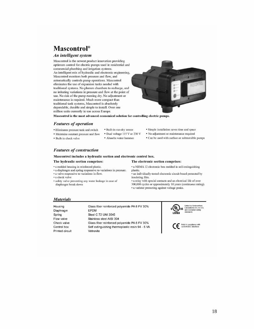
18