Embed Size (px)
Citation preview
DEFENCE ESTATE MAINTENANCE PLANNED WORKS
GUIDELINE FOR OPERATIONS AND MAINTENANCE MANUALS
Originally published: 8 September 2007 Updated: 15 Nov 10
6_90a OM Manual Spec 101115.doc
Page 2 of 47
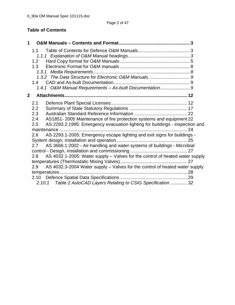
Table of Contents
1 O&M Manuals – Contents and Format....................................................... 3
1.1 Table of Contents for Defence O&M Manuals........................................ 3 1.1.1 Explanation of O&M Manual headings................................................ 3
1.2 Hard Copy format for O&M Manuals ...................................................... 5 1.3 Electronic Format for O&M manuals ...................................................... 8
1.3.1 Media Requirements........................................................................... 8 1.3.2 The Data Structure for Electronic O&M Manuals ................................ 9
1.4 CAD and As-built Documentation........................................................... 9 1.4.1 O&M Manual Requirements – As-built Documentation....................... 9
2 Attachments............................................................................................... 12
2.1 Defence Plant Special Licenses........................................................... 12 2.2 Summary of State Statutory Regulations ............................................. 17 2.3 Australian Standard Reference Information ......................................... 22 2.4 AS1851- 2005 Maintenance of fire protection systems and equipment 22 2.5 AS 2293.2:1995: Emergency evacuation lighting for buildings - inspection and maintenance ................................................................................................... 24 2.6 AS 2293.1-2005: Emergency escape lighting and exit signs for buildings - System design, installation and operation....................................................... 25 2.7 AS 3666.1:2002 - Air-handling and water systems of buildings - Microbial control - Design, installation and commissioning ............................................ 27 2.8 AS 4032.1-2005: Water supply – Valves for the control of heated water supply temperatures (Thermostatic Mixing Valves).................................................... 27 2.9 AS 4032.3-2004 Water supply – Valves for the control of heated water supply temperatures................................................................................................... 28 2.10 Defence Spatial Data Specifications .................................................... 29
2.10.1 Table 2 AutoCAD Layers Relating to CSIG Specification ............. 32

6_90a OM Manual Spec 101115.doc Page 3 of 47
1 O&M Manuals – Contents and Format The following section outlines the general contents/sections for an O&M Manual and the formats for Hard and Electronic Copies.
1.1 Table of Contents for Defence O&M Manuals The following table of contents headings have been developed with reference to AS/NZS 1388:1994. The headings to be used for Defence O&M Manuals are:
Title information, dates and author details Introduction and Scope Equipment or asset information/schedules Maintenance Operations Warranties, Certificates and Commissioning Spare Parts Suppliers or Help Contact Drawings and Reference Information
1.1.1 Explanation of O&M Manual headings The table below shows each O&M Manual heading and a short description of the content expected in that section. Heading Content overview Title information, dates and author details
The Project name, the location ie Base and the author or responsible contractor should be shown on the front cover of the Manual including the date of publication
Introduction and Scope
This section should be used to record information describing the systems, assets or equipment covered in the delivery of the total project and any other information that explains the overall use and application of the works covered by the Manual.
Equipment or asset information/schedule
This section should be used to record information describing items of equipment, assets, or elements of the work. The key issue is will the information help the new owner manage the Site better and comply with warranties or other obligations? For Defence this section will match the DEMS data requirements See section Error! Reference source not found. and Error! Reference source not found.
Maintenance
This section should be used to describe the maintenance schedules and lists the tasks that are required to be performed in order to maintain a piece of equipment/asset and hence prevent breakdown and or meet compliance requirements. The Schedule should be broken up in to a set of Routines by Frequency and Frequency Unit (ie 1 Month - Coils) and each

6_90a OM Manual Spec 101115.doc Page 4 of 47
Routine should list the tasks that are required to be performed in order to maintain a piece of equipment. Note some maintenance routines are covered under statutory regulations and care should be taken to ensure compliance.
Operations
This section should be used to record relevant information on the Operations of the assets; for example how to operate the system. It should also include important safety instructions and trouble shooting data to assist in solving simple problems to prevent expensive call outs. Also this section must meet the minimum requirements where a statutory regulation is relevant or where any integrated multi service/system is used.
Warranties, Certificates and Commissioning
This section should be used to record specific warranty and certificate reference information. The actual warranties and certificates are bound into the hard copy Manual. Electronic versions should be scanned and or uploaded as attached files in the drawings and references section of the electronic manual. Important test results relating to commissioning should also be included
Spare Parts
This section should be used to record relevant information on the Spare Parts data for the assets provided as part of the contract. It should be focused on spare parts that would allow the new owner to maintain and operate the plant with minimum “down time”. It may also include information on spare parts suppliers.
Suppliers or Help Contact
This section should be used to record information to allow the new owner to call for expert assistance in relation to the assets included in the project. This would include the main contractors, sub-contractors and suppliers.
Drawings and Other Reference Information
This section allows you to attach/bind and or upload information like as-built plans, copies of specifications, complete product manuals and other documents relevant to the works and the O&M Manual.
Note: Where no information is required under a section heading it can be left blank or the section heading can be deleted. Eg The FF&E Manual may not have any maintenance routines and therefore the section can be omitted.

6_90a OM Manual Spec 101115.doc Page 5 of 47
1.2 Hard Copy format for O&M Manuals This section describes the format required for Hard Copy (printed) O&M Manuals. The Hard Copy format is based on AS1388 and other Industry Sources. Defence Environmental Policy Defence environmental policy seeks to reduce the use of paper based systems and where possible electronic O&M Manuals should be used. It is preferable to print only those items of data that are needed from an electronic copy and not to request multiple copies of all documents. Generally
Generally the O&M Manuals must be in a readable and easily accessible format and presentation.
The use of illustrations and inclusion of relevant reference material is encouraged to ensure the user/reader is able to adequately understand the requirements for safe and proper operation and maintenance of the works.
The language style used in the document should be appropriate to the user or intended audience
Paper Sizes and Quality
All documents should preferably be produced in the international A4 paper size (210 mm × 297 mm). As-built documents and other larger material should preferably be A3 paper size ((297 mm x 420 mm). If other paper sizes are used, they should comply with AS 1612.
Printing material – Board/Paper and ink should be appropriate for the intended
use, e.g. strong enough to stand up to heavy usage and sufficiently opaque to avoid ‘showthrough’. As a guide 80GSM white copy paper is adequate for A4 and A3 documents.
Binding in Folders
Bind or contain each hard copy of the operations and maintenance manuals in white, durable, four ring hard cover binders in accordance with AS P5, not greater than 75 mm thick and , with the Project, Facility, Manual Name (Trade,Service or System Name eg Hydraulics Services) permanently marked on the spine and outside front cover with clear protection on the covers. Use of clear “Insert” type folders is permitted. Limit filling of binders to 60% of capacity
Any A3 size paper documents are to be folded to A4 size and located in the
Drawings and Reference Section of the Manual.
Manufacturers Manuals, booklets, pamphlets and other relevant reference material should be bound into the Drawings and Reference Section either within a

6_90a OM Manual Spec 101115.doc Page 6 of 47
suitable A4 clear plastic protection sheaf or direct hole punched and bound in the folder.
As-built documentation and plans which are not suitable for reduction to A3 size
must be neatly folded to A4 size and bound into the Folder either in a suitable A4 clear plastic protection sheaf or direct hole punched with reinforced hole protectors and bound in the folder such that it can be infolded and re-folded easily
CD,s, DVD,s and other relevant data media must be bound into the Manual in a
suitable clear plastic holder with each CD/Media clearly labelled with the Project Title, Location, Manual Name and Short description of the contents. Also any instructions required to operate the media must be either included in the plastic protector or bound into the Manual in front of the media.
Presentation
Front Cover will contain the following; o Project Title – the name commonly used to describe the works or project,
eg Stage 2 Redevelopment etc o The Location Name – the name of the Defence Base/facility on which the
works are undertaken (where a project spans a number of locations separate O&M Manuals are to be provided for each Base)
o The Manual Name – the title of the trade, service or systems covered by this Manual, eg Electrical Fire Services
o The Author – the author or organisation responsible for creation of the Manual eg Builder and or sub-contractor
o The date of publication o Other Information – other relevant information that will assist the reader to
use the Manual and may also include appropriate designs, logos and the like such that the key information above is still clearly visible and readable
Folder/Manual Spine Titles can be shortened or abbreviated to identify the
Project Title, Location and Manual Name. Other information can be included subject to available space and so as to not make the key information unreadable from a distance.
Folder/Manual Spine layout - printing should commence from the top and be
readable downwards when the document is standing up and upright, or be readable left to right when the document is lying face-up. On wide spines printing may be readable left to right when the document is standing up. Spines should be free of printed information on the lowermost 35 mm when upright to allow clear space for user referencing information, e.g. library indexing systems.
Typefaces or Fonts for text should be clear and legible. The requirements of
legibility, photocopying, facsimile (fax) transmission, microfiche production and optical character reading should be considered in the choice of typeface, inter-word spacing, line spacing and line length or column width. Where coloured inks

6_90a OM Manual Spec 101115.doc Page 7 of 47
are used, products should be selected which do not reduce legibility when photocopied or transmitted by fax
As a general rule text should be :
o Colour – black (use of other colours is to be restricted as all pages are to
be easily photocopied or faxed) o Main text size - 9 pt up to 12 pt. o Title Text size – 18 pt or higher o Page footers size – 8 pt to max 12 pt to suit layout o Fonts should be Times Roman, Arial, Helvetica or other approved font o Use of bold, italics, capitals should be to improve readability only.
Page Headers And Footers - Every page should carry a page number, preceded
where appropriate by a document number. The title of the document (abbreviated, if necessary) should appear on each page as well as the date of issue. Page numbering of attached separate documents eg Product Booklet is not required.
Print text on A4 pages on one side only in a clear typeface with a 35 mm margin
for binding.
Section Identification/Dividers - each section should be indicated by means such as coloured divider leaves, cards, section tabs, or edge markings on pages. Edge markings should be not less than 3 mm wide.
Contents List should appear on the first or second page of each O&M Manual
showing the sections contained in that Folder in matching sequential order to the section dividers/tabs. Page numbers and other reference tags may be shown however it is accepted that with a number of added documents like Manufacturers booklets complete page numbering is not always achievable.
Margins - To allow for punching and binding, margins on documents should not
be less than 20 mm wide.
Illustrations, Technical Drawings, Tables And Charts - All illustrations, technical drawings, tables and charts should carry descriptive titles explaining the name of the document and a short description (eg Title - As-built Plans Sewer works No 123/A. Description - Shows’ the location, off-sets, IL depth and layouts for sewer works to Building A100). Instructions and notes referring to such drawings, tables and charts should be positioned in such a way that they are fully visible in relation to these drawings, tables and charts. Illustrations should be clear and explanatory.
Technical drawings should be drawn to stated ratio scales and comply with AS
1100 or NZS/AS 1100. Symbols and other graphic conventions should comply

6_90a OM Manual Spec 101115.doc Page 8 of 47
with AS 1100, AS 1101, NZS/AS 1100, NZS/AS 1101.3 or other relevant Australian or New Zealand Standards.
Photographs should be used to supplement information given elsewhere, for
aesthetic reasons, or to clarify installation and maintenance data. Where photographs are used, in order to aid reproduction they should be of adequate quality and clarity
Units Of Measurement And Presentation -Metric (SI) units and international unit
symbols should be used in technical data and comply with AS 1000 and AS 1155 or NZS 6501, except where legislation states otherwise.
Technical terms should be those used in SAA HB25 and SAA HB50 or NZMP
4212. Where a number of special Defence terms or acronyms are used a table should be included in the Introduction and Scope Section explaining each term.
1.3 Electronic Format for O&M manuals The electronic format for O&M Manuals has been developed using the basic standard Hard Copy approach with reference to Industry Standards and is to include.
A PDF file containing all the documentation found in the Hard Copy Manuals or
A WebFM electronic O&M Manual data file containing all the documentation inputted via the Internet site for that project. (Note the WebFM electronic O&M Manual system will also reproduce the inputted text data in a PDF format file).
The electronic version of the O&M manuals is to also be accompanied by a Metadata file so that the manuals can be uploaded into the National Spatial Information Management System (NSIMS). The Defence Metadata standard is specified in the DSG Spatial Data Management Plan Sect 5 Spatial Metadata Specification. To assist in the development of Metadata files, a Metadata Entry Tool (MET) is freely available on the IM. Defence staff can access it on the DRN at http://intranet.defence.gov.au/im/business/spatial/met/main.htm , and Contractors can access it on the internet at http://www.defence.gov.au/im/business/spatial/met/main.htm
1.3.1 Media Requirements
All electronic O&M Manuals shall be copied to a CD ROM(s) data Disk and all data should be accessible either as PDF file format or using the WebFM database application
6_90a OM Manual Spec 101115.doc Page 9 of 47
CD ROMs are to be presented in Clear Slim Jewel Cases or where multiple CD ROM’s are required for a single Project they are to be bound into a a suitable clear plastic CD holder
The holder used must be labelled in the same manner as for Hard Copy Manuals, Title cover, Spine and Project information
A short written instruction sheet (s) are to be included in the Folder explaining how to use and access the CD ROMs
When submissions consist of 2 or more CD ROMs, each CD ROM shall be numbered sequentially, including the total number of CD ROMs in the submission (i.e. 3 of 6).
CD ROM(s) shall be formatted single session; finalized disk; Joliet or ISO 9660 with electronically printed CD label with the following project information:
o Project Title and o Location. o O&M manual Title and Volume Number if required o Date submitted (i.e. December 14, 2004) o Name of Contractor/Author
1.3.2 The Data Structure for Electronic O&M Manuals The number of CD ROM’s is to be limited to the minimum required to hold the actual data for all the O&M Manuals. Separate CD ROMS’s are not to be provided for each Trade or Manual and preferably all should be held on one single Project CD.
1.4 CAD and As-built Documentation As-built plans and designs are an integral part of any O&M Manual. The objectives of providing as-built plans/documents are:
To document locations for services, systems and plant including those that are in-ground and concealed
To assist Facility Users and Maintenance Staff to locate services and equipment easily
To assist in future re-developments and new works that may add or reconfigure existing systems
To reduce the risk of system failures and ensure safe work through provision of accurate documentation
Compliance with Statutory Regulation for provision/retention of as-built documentation (ie Cooling Towers, Emergency Lighting etc)
1.4.1 O&M Manual Requirements – As-built Documentation As-built plans and CAD designs must be included in the O&M Manuals as both hard copy and electronic documents. The format for the plans (Hard Copy or Electronic)

6_90a OM Manual Spec 101115.doc Page 10 of 47
shall be consistent with the Defence Support Group (DSG) Spatial Data Management Plan. Hard Copies Hard Copy documents should be:
Folded and bound into the O&M Manuals in the Drawings and Reference Section of the relevant Manual.
Number of copies shall be one complete set of as-builts per set of O&M Manuals as required in the contract
Wherever possible all as-built plans should be printed in A3 size folded into the O&M Manual for easy access
Full size copies of as-built plans may be folded and bound into the relevant Manuals in a clear plastic protector or
Can be supplied full size, unfolded in a separate and suitable Plan Folder only with the approval of the Defence Project Manager and or Regional Representative
Electronic Copies Electronic copies of plans should be:
Data files in both CAD (DWG) and PDF formats copied to CD complete with a reference directory corresponding to each O&M Manual title and each data file name denoting the service covered
Suitably labelled CD(s) inserted into a clear plastic A4 holder and bound into the Drawings and Reference Section of the relevant Manuals or
Where the WebFM system is used
o copies of the CAD and PDF data files are uploaded into the on-line O&M
Manual System under the relevant O&M Manual and Drawings and Reference Section.
o All as-built data files must have a suitable Heading and Description of the documents, eg Heading - Sewer Installation Plan, Description - As-built plans showing sewer layouts, IL’s, building off sets, manholes, IO’s and pipe sizes.
o The final WebFM electronic O&M Manual CD(s) will include all uploaded drawing files for access by Defence
Where the contract required a separate As-built CD the CD(s) must be suitably
labelled, referenced and housed in a sturdy CD Case (number of copies per the contract requirement)
All Electronic CAD files/as-built plans must conform to the Defence Spatial Data Specifications requirement.

6_90a OM Manual Spec 101115.doc Page 11 of 47
Further information on CAD and As-built information can be found in section 2.10 in this document.

6_90a OM Manual Spec 101115.doc Page 12 of 47
2 Attachments
2.1 Defence Plant Special Licenses Plant Special Licences (PSL) are a Statutory Requirement under the Occupational Health and Safety (Commonwealth Employment) Act 1991. Defence is required to maintain PSL’s for those items shown below. It is therefore a requirement that O&M Manuals must include sufficient information to meet the Commonwealth’s requirements. The following is an excerpt from the Occupational Health and Safety (Commonwealth Employment) (National Standards) Regulations 1994, Statutory Rules 1994 No. 414 as amended made under the Occupational Health and Safety (Commonwealth Employment) Act 1991. For further information refer to:
www.comcare.gov.au/publications/index.html www.comlaw.gov.au/ComLaw/Legislation
Requirements to Provide Information in O&M Manuals Under the regulation the following is required of the manufacturer and in turn passed on by the installer to Defence. Division 3 Duties of a supplier of plant, sect 4.06 Provision of information “A manufacturer of plant that the manufacturer knows, or ought reasonably to expect, will be used by employees at work, must take all reasonably practicable steps to make available to the employer information concerning: (a) the systems of work necessary for the safe use of the plant; and
(b) the knowledge, training or skill needed by a person inspecting or testing the plant; and
(c) relevant emergency procedures.” Also that the information provided meets the following Division 5 Duties of an employer, sect 4.14 Installation and commissioning of plant, sub sect (2) The employer must take all reasonably practicable steps to ensure that:
(a) the installation, erection and commissioning of the plant are undertaken by a competent person; and
(b) the person undertaking the installation, erection or commissioning is given the information that is necessary to allow the plant to be installed, erected and commissioned in a manner that minimises the risk to the health and safety of a relevant person; and

6_90a OM Manual Spec 101115.doc Page 13 of 47
Schedule 5 Plant standards (paragraphs 4.05 (2) (d) and 4.51 (4) (b))
Item Australian Standard
Title
1 AS/NZS 1200:2000 ‘Pressure equipment’
2 AS 1418
AS 1418.1-2002 ‘Cranes (including hoists and winches) – Part 1: General requirements’
AS 1418.2-1997 ‘Cranes (including hoists and winches) – Part 2: Serial hoists and winches’
AS 1418.3-1997 ‘Cranes (including hoists and winches) – Part 3: Bridge, gantry and portal cranes (including container cranes)’
AS 1418.4:2004 ‘Cranes (including hoists and winches) – Part 4: Tower cranes’
AS 1418.5-2002 ‘Cranes (including hoists and winches) – Part 5: Mobile and vehicle loading cranes’
AS 1418.6-1988 ‘Cranes (including hoists and winches) (known as the SAA Crane Code) – Part 6: Guided storing and retrieving appliances’
AS 1418.7-1999 ‘Cranes (including hoists and winches) – Part 7: Builders hoists and associated equipment’
AS 1418.8-2002 ‘Cranes (including hoists and winches) (known as the SAA Crane Code) – Part 8: Special purpose appliances’
AS/NZS 1418.9-1996
‘Cranes (including hoists and winches) – Part 9: Vehicle hoists’
AS 1418.10-1996 ‘Cranes (including hoists and winches) – Part 10: Elevating work platforms’
AS 1418.12-1991 ‘Cranes (including hoists and winches) – Part 12: Crane collector systems’
AS 1418.13-1996 ‘Cranes (including hoists and winches) – Part 13: Building maintenance units’
AS 1418.14-1996 ‘Cranes (including hoists and winches) – Part 14: Requirements for cranes subject to arduous working conditions’
AS 1418.15-1994 ‘Cranes (including hoists and winches) – Part 15: Concrete placing equipment’
AS 1418.16-1997 ‘Cranes (including hoists and winches) – Part 16: Mast climbing work platforms’
AS 1418.17-1996 ‘Cranes (including hoists and winches) – Part 17: Design and construction of workboxes’
AS 1418.18-2001 ‘Cranes (including hoists and winches) – Part 18: Crane runways and monorails’
3 AS 1576
AS/NZS 1576.1- ‘Scaffolding – Part 1: General requirements’

6_90a OM Manual Spec 101115.doc Page 14 of 47
Item Australian Standard
Title
1995
AS 1576.2-1991 ‘Scaffolding – Part 2: Couplers and accessories’
AS/NZS 1576.3-1995
‘Scaffolding – Part 3: Prefabricated and tube-and-coupler scaffolding’
AS 1576.4-1991 ‘Scaffolding – Part 4: Suspended scaffolding’
AS/NZS 1576.5-1995
‘Scaffolding – Part 5: Prefabricated splitheads and trestles’
AS/NZS 1576.6-2000
‘Scaffolding – Part 6: Metal tube-and-coupler scaffolding – Deemed to comply with AS/NZS 1576.3’
4 AS 2030
AS 2030.1-1999 ‘The verification, filling, inspection, testing and maintenance of cylinders for storage and transport of compressed gases – Part 1: Cylinders for compressed gases other than acetylene’
AS 2030.2-1996 ‘The verification, filling, inspection, testing and maintenance of cylinders for storage and transport of compressed gases – Part 2: Cylinders for dissolved acetylene’
AS 2030.4-1985 ‘The verification, filling, inspection, testing and maintenance of cylinders for storage and transport of compressed gases – Part 4: Welded cylinders-insulated’
5 AS/NZS 3509:2003 ‘LP gas fuel vessels for automotive use’
6 AS 3533.1-1997 ‘Amusement rides and devices – Part 1: Design and construction’
7 AS 3920.1-1993 except the provisions about hazard levels
‘Assurance of product quality – Part 1: Pressure equipment manufacture’
8 AS 4343-1999 ‘Pressure equipment — Hazard levels’

6_90a OM Manual Spec 101115.doc Page 15 of 47
Schedule 6 Types of plant (paragraph 4.19 (2) (a), subregulations 4.40 (1), 4.47 (1), 4.49 (1), 4.51 (1) and 4.56 (1))
Part 1 Plant requiring registration or notification of design
Item Description of plant
1 Pressure equipment, other than pressure piping, that has a hazard level of A, B, C or D, determined in accordance with AS 4343-1999 ‘Pressure equipment – Hazard levels’ and specifically covered by the standard mentioned in item 1 of Schedule 5
2 Gas cylinders covered by the standards mentioned in item 4 of Schedule 5
3 Tower cranes1
4 Building maintenance units
5 Hoists, with a platform movement in excess of 2.4 metres, designed to lift people1
6 Work boxes suspended from cranes
7 Amusement structures covered by the standard mentioned in item 6 of Schedule 5, other than class 1 structures
8 Prefabricated scaffolding
9 Boom-type elevating work platforms
10 Gantry crane1:
(a) with a safe working load greater than 5 tonnes; or
(b) designed to handle molten metal or dangerous good2
11 Bridge cranes1:
(a) with a safe working load of greater than 10 tonnes; or
(b) designed to handle molten metal or dangerous goods2.
12 Vehicle hoists1
13 Mast climbing work platforms1
14 Mobile cranes with a safe working load greater than 10 tonnes1

6_90a OM Manual Spec 101115.doc Page 16 of 47
Part 2 Plant requiring a licence
Item Description of plant
1 Boilers:
(a) that have a hazard level of A, B or C determined in accordance with AS 4343-1999 ‘Pressure equipment – Hazard levels’; and
(b) are specifically covered by the standard mentioned in item 1 of Schedule 5
2 Pressure vessels:
(a) that have a hazard level of A, B or C, determined in accordance with AS 4343-1999 ‘Pressure equipment – Hazard levels’; and
(b) are specifically covered by the standard mentioned in item 1 of Schedule 5, other than:
(i) gas cylinders mentioned in the standard mentioned in item 4 of Schedule 5; and
(ii) LP gas fuel vessels for automotive use mentioned in AS/NZS 3509:2003 ‘LP gas fuel vessels for automotive use’; and
(iii) serially produced pressure vessels mentioned in AS 2971:2002 ‘Serially Produced Pressure Vessels’
3 Tower cranes1
4 Building maintenance units
5 Amusement structures covered by the standard mentioned in item 6 of Schedule 5, other than class 1 structures
6 Truck-mounted concrete placing units with booms1
7 Mobile cranes with a safe working load greater than 10 tonnes1
Note 1 For the purposes of licensing, cranes and hoists in Schedule 6 exclude those that are manually powered, elevating work platforms or tow trucks.

6_90a OM Manual Spec 101115.doc Page 17 of 47
2.2 Summary of State Statutory Regulations The following is a summary of State Regulations that encompass:
Public Health (Control of Legionella AS 3666) and Essential Services (AS 1851)

6_90a OM Manual Spec 101115.doc Page 18 of 47
© Commonwealth of Australia Produced by the enHealth Council Secretariat - http://enhealth.nphp.gov.au/index.htm Appendix 1 - Regulatory approaches by Australian States and Territories to the prevention of legionellosis
Regulatory approaches Legionella 120601.doc
1
Jurisdiction Acts Regulations Standards, codes or
guidelines Responsible State or Territory agency
Enforcement agencies
Queensland Workplace Health & Safety Act 1995
Workplace Health & Safety Regulations (1997)
Plant Advisory Standard Supplement No.2 (2000) Legionella Control in Airconditioning Units & Cooling Towers
Department of Industrial Relations
DIR-Division of Workplace Health & Safety
New South Wales
Public Health Act 1991 Public Health (Microbial Control) Regulation 2000
Code of Practice for the Control of Legionnaires’ Disease (under review) Code of Practice Thermostatic mixing valves in Health Care Buildings (under review) AS/NZS 3666 parts 1,2 & 3
NSW Health Department and Local government
NSW Health Department and Local government
Health Act 1958 Health (Legionella) Regulations 2001
Guidelines for the control of Legionnaires’ disease
Department of Human Services
Department of Human Services
Building Regulations 1994
Building Code of Aust F4.5 & I1.2 and AS/NZS 3666
Building Control Commission
Authorised officers
Victoria
Building Act 1993, as amended by the Building (Legionella) Act 2000
Building (Legionella Risk Management) Regulations 2001
A guide for developing Risk Management Plans for Cooling Tower Systems Managing the Risk of Legionnaires’ Disease: Supplementary Notes for Hospitals
Department of Human Services
Department of Human Services

6_90a OM Manual Spec 101115.doc Page 19 of 47
Jurisdiction Acts Regulations Standards, codes or guidelines
Responsible State or Territory agency
Enforcement agencies
Building (Cooling Towers Register) Regulations 2001
Guide to Registering a Cooling Tower System
Building Control Commission
Department of Human Services
Victoria (continued)
Building Act 1993, as amended by the Building (Legionella) Act 2000 (continued) Plumbing (Cooling
Towers) Regulations 2001
AS/NZS 3666 (Mechanical services work only) A Code of Good Practice for the Servicing, Maintenance & Recommissioning of Mechanical Services Plant & Equipment Technical Solutions 6: Hot water plumbing Technical Solutions – 7: Mechanical Services
Plumbing Industry Commission
Plumbing Industry Commission
Tasmania Public Health Act (1997) Guidelines for Legionella (2001)
Department of Health and Human Services
Department of Health and Human Services
South Australia Public and Environmental Health Act (1987)
General provisions of Act. Specific Regulations proposed
AS/NZS 3666 and HB-32 as base reference documents. AS/NZS 3500.4.2 by reference. Proposed “Standard for the Control of Legionella in Manufactured Water System in South Australia”
Department of Human Services (DHS)
Local Government and DHS in unincorporated areas.

6_90a OM Manual Spec 101115.doc Page 20 of 47
Jurisdiction Acts Regulations Standards, codes or
guidelines Responsible State or Territory agency
Enforcement agencies
South Australia (continued)
Development Act (1993) Building Code of Australia
AS/NZS 3500.4.2 Local Government Department for Transport, Urban Planning and the Arts (DeTUPA)
Local Government, (DeTUPA in unincorporated areas).
Western Australia
Health Act 1911 Health (Air Handling and Water Systems) Regulations 1994
AS 3666 (1989) Health Department of WA
Local Government
Australian Capital Territory
Public Health Act 1997 ACT Cooling Towers and Warm Water Storage Systems Code of Practice 2000 (Code of Practice)
ACT Department of Health, Housing and Community Care
ACT Department of Health, Housing and Community Care
Northern Territory
Public Health Act 1952 Work Health Act 1986
Building Regulations 1993
Building Code of Aust F4.5 & I1.2, 1668.2 & AS/NZS 3666.1 Guide on Legionnaire’s Disease Guidance for the Control of Legionella - NEHF
Department of Lands Planning & Environment Department of Industries & Business Territory Health Services
Department of Lands Planning & Environment Department of Industries & Business Territory Health Services

6_90a OM Manual Spec 101115.doc Page 21 of 47
Statutory law obligation in relation to compliance with AS 1851 – 2005 (Fire Protection Association Australia White Paper 2005) State Legislation Controlled By Essential Service name Australian Capital Territory
Building Act 2004 Building Regulations 2004
ACT Fire Brigade Active Fire Safety Systems
New South Wales Environmental Planning and Assessment Act 1979 Environmental Planning and Assessment Regulations 2000
Department of Planning Essential Fire Safety Measures
Victoria Building Act 1993 Building (Interim) Regulations 2005
Building Commission Essential Safety Measures
Queensland Fire and Rescue Service Act 1990 Fire and Rescue Service Regulations 1991
Queensland Fire and Rescue Service
Fire Safety Installations
Tasmania Building Act 2000 Building Regulations 2004
Department of Infrastructure, Energy and Resources
Essential Safety and Health Features / Measures
South Australia Development Act 1993 Development Regulations 1993
Planning SA Essential Safety Provisions
Western Australia No specific essential service provisions other than those prescribed in BCA. General Building Control matters are covered under Local Government (Miscellaneous Provisions) Act 1960 and Building Regulations 1989
Building Codes and Regulations Branch of Department of Housing and Works
No defined term
Northern Territory Building Act Building Regulations
Department of Infrastructure Building Advisory Services Branch
Safety Measures

6_90a OM Manual Spec 101115.doc Page 22 of 47
2.3 Australian Standard Reference Information The following summary information is provided as a guide only to content of O&M Manuals. Specific reference must be made to the current relevant Australian Standard for more accurate information on required contents for O&M Manuals.
2.4 AS1851- 2005 Maintenance of fire protection systems and equipment AS 1851-2005: Maintenance of fire protection systems and equipment This Standard sets out requirements for the inspection, test, preventative maintenance and survey of fire protection systems and equipment. It covers the statutory maintenance requirements of the Essential Fire Safety Measures referred to in the Environmental Planning and Assessment Regulation and as such its requirements are mandatory. The Standard documents the statutory maintenance, testing and recording requirements for: • Automatic fire sprinkler systems • Fire pumpsets • Fire hydrant systems • Delivery lay flat fire hose • Fire detection systems • Smoke alarms and heat alarms • Fire alarm monitoring systems • Sound systems for emergency purposes • Intercom systems for emergency purposes • Gaseous fire extinguishing systems • Fixes aerosol fire extinguishing systems • Open nozzle water mist fire extinguishing systems • Fire hose reels • Portable and wheeled fire extinguishers • Fire blankets • Passive fire and smoke containment systems • Fire and smoke control features of HVAC systems • Emergency evacuation procedures The implications of this Standard on the O&M Manuals content are:
All systems / equipment installed must be documented in the manuals. This includes fans, dampers, hose reels, hydrants etc.
Details relating to the operation and ongoing maintenance, testing and reporting of the systems / equipment (including manufacturers recommendations) must be included;
Include documentation relating to fire engineered solutions (if applicable) to allow for ongoing certification;
Certifications for the installation, testing and commissioning of these systems / equipment must also be included.

6_90a OM Manual Spec 101115.doc Page 23 of 47
Other specific sections within the standard pertaining to the O&M Manual content requirements include:
Clause 1.9 – Design, installation and commissioning standards Clause 18.2.4 – Documentation (Fire and Smoke Control Features of HVAC
systems) Clause 1.9 – Design, installation and commissioning standards This clause recommends that O&M Manuals must include the maintenance routines for pre-engineered fire protection systems in accordance with the manufacturers’ instructions. Clause 18.2.4 – Documentation (Fire and Smoke Control Features of HVAC systems) The following clauses under Clause 18.2.4 identify specific O&M Manual content requirements for HVAC. . Clause 18.2.4.1 General The property owner or occupier must maintain records required to implement the maintenance program which shall include the following: • A schedule of essential functionality and performance requirements; • Operating and maintenance manuals; • Maintenance schedule; • Maintenance records; • Plant register; • Plant history sheet; and • Diagram(s) of the installation. Clause 18.2.4.2 Schedule of essential functionality and performance requirements A schedule indicating the correct fire mode operation of all components such as fan and dampers and the required performance parameters of the system must be documented in the O&M Manual. The schedule of essential functionality and performance requirements shall incorporate:
Unambiguous description of HVAC system operation in fire mode; Provision to record the status and/or performance (correct or faulty) of: Operation of every fan or air-handling (AHU) in normal duty; Operation of every fan or AHU during general fire alarm condition; Operation of every motorised damper required to operate during a general or
zone specific fire alarm condition; Every required make-up airflow path (natural or via door or damper); Manual override control from the fire fan control panel (FFCP); and Fan or damper indicator lamps on the FFCP. Describe specific HVAC function linked to specific fire alarm zone reference
and record correct operation of fire/HVAC function; Record that the appropriate fire systems and HVAC personnel have both been
involved in the checking / test process, so that the fire / HVAC interface can be seen to have been demonstrated;
6_90a OM Manual Spec 101115.doc Page 24 of 47
Demonstrate that the essential HVAC systems are capable of performing to the standard to which they were originally installed; and
Provide floor plans showing smoke alarm zones necessary for the development of the schedule of essential functionality and performance.
A copy of the functionality forms must be included in the manuals as per the examples provided in AS1851:2005 Clause 18.2.4.3 – Operating and maintenance manuals (HVAC) Operating and maintenance manuals shall be provided for all plant, equipment and systems and must include at least the following:
The performance criteria for all fire and smoke control features of the HVAC systems and also identify alternative fire engineered solutions and design criteria;
Results of initial commissioning tests for all fire and smoke control features of the HVAC systems;
Physical details of the plant, equipment and systems; Supplier’s recommendations on maintenance and management; Recommended cleaning methods and dismantling instructions; Start-up, operating and shutdown procedures; and Particulars of the maintenance program.
Clause 18.2.4.4 Maintenance Schedule (HVAC) The O&M Manual shall list all required items of plant and equipment and operational features to be subjected to the maintenance routines set out in this Standard. Clause 18.2.4.5 Plant Register (HVAC) The O&M Manual shall list all items of plant and equipment that require inspection as a prerequisite to maintenance and shall describe their locations within the building. This shall include design data and unit capacities in sufficient detail to order a replacement of equivalent performance. Clause 18.2.4.7 Diagrams of the installation (HVAC) Plans included in the O&M Manual must be floor plans showing smoke alarm zones necessary for the development of the system functionality test chart.
2.5 AS 2293.2:1995: Emergency evacuation lighting for buildings - inspection and maintenance
This Standard sets out the periodic inspection and maintenance procedures which are necessary to ensure that emergency evacuation lighting systems will be in a state of readiness for operation at all times. It applies to central and single-point emergency lighting systems, as defined in AS 2293.1. This Standard relates to equipment referred to in the Environmental Planning and Assessment Regulation under the Essential Fire Safety Measures. Therefore its requirements are statutory. While AS 2293.2 deals with the specific maintenance routines it directs the reader to AS 2293.1 Section 7 for specific O&M Manual requirements to assist in conducting the inspection and maintenance checks required by this Standard.

6_90a OM Manual Spec 101115.doc Page 25 of 47
Not withstanding this, O&M Manuals must include maintenance instructions for the emergency evacuation lighting in accordance with this Standard. Appendix A of the Standard requires the following information to be provided to facilitate the maintenance of batteries and battery chargers: • Instructions for checking electrolyte levels; • Battery float voltage limits; • Cell float voltages / electrolyte density; and • Instructions for neutralising spilt battery liquid. Appendix B of this Standard suggests that instructions for the cleaning of the luminaries are to be included in the O&M Manual.
2.6 AS 2293.1-2005: Emergency escape lighting and exit signs for buildings - System design, installation and operation
This Section sets out requirements for the operational performance, arrangement and control of emergency lighting systems. It also specifies a discharge test, applicable at the time of commissioning the completed installation, to check that the appropriate duration of operation is achieved. This Standard relates to equipment referred to in the Environmental Planning and Assessment Regulation under the Essential Fire Safety Measures. Therefore its requirements are statutory. Section 7 – Information required for maintaining the system This section of the standard requires:
An operating and maintenance manual in a durable hard-bound cover shall be provided for each emergency lighting installation
The operation and maintenance manuals should contain the following: The data required to carry out the maintenance procedures in AS2293.2, as
appropriate. The information required by Clause 7.2.2 for Central Systems or Clause 7.2.3
for Single Point Systems, as appropriate (listed below). The information listed in Appendix A of AS/NZS 2293.2, where applicable, for
the guidance of maintenance personnel (listed in the previous section) According to the standard, a ‘centrally supplied’ (emergency lighting) system is a system of emergency lighting in which a number of emergency luminaires, or exit signs, or both are supplied from a common power source. Within a building there may be more than one power source, each of which supplies the emergency luminaires and exit signs in a particular section of the building. A ‘Single-point’ (emergency lighting) system, on the other hand is a system of emergency lighting employing only self-contained type emergency luminaires. Clause 7.2.2 Information relating to central systems For central systems, the O&M Manual shall contain the following information:
Battery data. Battery charger data Inverter data

6_90a OM Manual Spec 101115.doc Page 26 of 47
Installation data which includes As-installed plans showing: the location of all emergency lighting equipment including emergency
luminaires and exit signs; the supply circuits; all submains cable routes; luminaire/exit sign and lamp details; Each emergency luminaire and exit sign with a separate designation for
identification purposes; and a legend to identify the type of luminaire or exit sign or alternatively, a detailed
schedule listing the required information may be supplied in lieu of installation plans.
Wiring diagrams with As-installed circuit diagrams covering the entire emergency lighting installation external to the battery charger and inverter panels. These diagrams shall show cable sizes, circuit-breaker or fuse ratings, relay or contactor ratings and the total emergency lighting maximum demand.
A maintenance schedule setting out step by step the tests required by AS 2293.2 at each of the nominated intervals.
7.2.3 Information relating to single-point systems For single-point systems, the operating and maintenance manual shall contain the following information:
Installation data As-installed plans showing: the location of all self-contained emergency luminaires and exit signs; their supply circuits (see also Clause 7.2.5); Each emergency luminaire and exit sign shown shall be given a separate
number for identification purposes; and a legend to identify the type of luminaire or exit sign. Alternatively, a detailed
schedule listing the required information may be supplied in lieu of installation plans.
Connection diagram As-installed circuit diagrams showing the typical external connections for each type of self-contained emergency luminaire and exit sign;
Luminaire data full technical data including lamp information for each type of self-contained emergency luminaire and exit sign;
A maintenance schedule setting out step by step the tests required by Section 3 of AS/NZS 2293.2 at each of the nominated intervals;
Where facilities are provided for automatic discharge testing, the operating and maintenance manual shall contain the following information:
The location of any control and indicating panels, if applicable; Details of the operation of the system, including the meanings given to the
indications of system status that are provided; Where a centralized system of control is used, identification of the association
between individual emergency luminaires and exit signs and the controllers to which they are connected.

6_90a OM Manual Spec 101115.doc Page 27 of 47
2.7 AS 3666.1:2002 - Air-handling and water systems of buildings - Microbial control - Design, installation and commissioning
The objective of this standard is to assist in the control of micro-organisms in building systems, particularly those associated with legionnaire’s disease, Pontiac fever, hypersensitivity pneumonitis and humidifier fever. This standard is linked to the NSW Public Health Act in NSW and other State Acts and therefore constitute a legal/statutory requirement. Section 2.6 – Evaporative air handling equipment This section states that O&M Manuals shall include at least the following:
Physical details of the plant, equipment and systems and pre-treatment carried out.
Recommendations on maintenance including water treatment maintenance and management.
Recommended cleaning, disinfection and emergency decontamination procedures.
Start-up, operating and shut-down procedures. Particulars of the maintenance management program including plant servicing
and cleaning schedules. Please note that O&M Manuals and maintenance service records must be readily available at the site for inspection by regulatory authority upon request.
2.8 AS 4032.1-2005: Water supply – Valves for the control of heated water supply temperatures (Thermostatic Mixing Valves)
This Standard specifies the requirements for the design, construction, testing performance and means of compliance for metallic-bodied thermostatic mixing valves. (According to the standard, a thermostatic mixing valve (TMV) is mixing valve in which the temperature of the water from the mixed water outlet is automatically controlled to a pre-selected temperature that is suitable for direct contact with the skin). This Standard relates to “regulated” equipment that has been identified in the Public Health Act and is therefore mandatory. Sections within the standard pertaining to the O&M Manual content requirements include: • Clause 1.8 – Scope and General • Appendix C Clause 1.8 requires that each valve shall be accompanied by installation, commissioning, field-testing and maintenance instructions, in English, in accordance with Appendix C. Appendix C of this Standard requires that the O&M Manual maintenance instructions include the following:
Name and address of the manufacturer and the relevant agent; Complete written sequential maintenance details in accordance with AS
4032.3 for the referenced thermostatic mixing valve, including an exploded view with reference to all parts;

6_90a OM Manual Spec 101115.doc Page 28 of 47
Identification of spare parts including lubricants and sealants for recommended routine servicing;
Procedures for problem-solving and corrective actions; Instruction that the maximum time interval between routine services is 12
months; and Details of any other relevant instructions.
2.9 AS 4032.3-2004 Water supply – Valves for the control of heated water supply temperatures
This Standard specifies minimum requirements for field-testing and maintenance/ replacement of thermostatic mixing valves, tempering valves and end-of-line temperature actuated devices. The standard lists three main types of valves: • Thermostatic Mixing Valves; • Temping Valves; and • End-of Line temperature actuated devices. Thermostatic Mixing Valves According to Appendix B of the Standard, the following shall be reported: (a) The model, manufacturer and identification of the valve. (b) Location of the valve (c) Temperatures recorded during test. (d) Details of tests, maintenance and parts replaced. (e) Reference to this test method, i.e., AS 4032.3, Appendix B. Temping Valves According to Appendix C of the Standard, the following shall be reported: (a) The model, manufacturer and identification of the valve. (b) Temperatures recorded during test. (c) Details of test, maintenance and parts replaced. (d) Location of the valve (e) Reference to this test method, i.e., AS 4032.3, Appendix C. End-of Line temperature actuated devices According to Appendix D of the Standard, the following shall be reported where required: (a) The location of the device. (b) Temperatures recorded in Step D4(d). (c) Details of the device replacement. (d) Reference to this test method, i.e., AS 4032.3, Appendix D.

6_90a OM Manual Spec 101115.doc Page 29 of 47
2.10 Defence Spatial Data Specifications The Defence Support Group (DSG) Spatial Data Management Plan (SDMP) has been developed to:
Provide adequate standards for delivery of Spatial data to Defence Standardise the presentation of Spatial data in all DSG Regions
The document is available on the IM at http://intranet.defence.gov.au/im/business/spatial/main.htm#sdmp for internal Defence users, or at http://www.defence.gov.au/im/business/spatial/main.htm#sdmp for external users. The SDMP is broken into a number of sections. The following sections should always be provided to contractors where their scope of work includes any spatial data creation and or maintenance:
Section 1 - Guiding Principles Section 5 - DSG Spatial Metadata Specification Section 6 - Baseline Spatial Data Specifications Section 7 - Spatial Data Specifications
o Select the relevant part/s for Section 7: o Part 1 - Survey Specifications for Facility Detail Capture o Part 2 - CAD Specifications for Facility Detail Data o Part 3 - Specification for Capture and Presentation of Spaces Data o Part 4 - Specification for the Capture and Presentation Mapping of
Garrison Support Services o Part 5 - Specification for the Capture of Communications Information o Part 6 - Specification for Capture and Supply of Aerial Photography and
Satellite Imagery o Part 7 - Environmental Data Specifications
The following is an overview. (Always refer to the full document for detailed information). Part 1, Survey Specifications for Facility Detail Capture
Used to amend and update existing spatial databases, assist in planning and provide a permanent record of development.
All as-built drawings shall be in accordance with ISO 19115 and any other relevant Australian or International standards. Refer to the DSG SDMP Section 7 – Spatial Data Specifications, Part 1 for more information on the Standards applicable to DSG Spatial data.
Detail Survey is to include all significant features and Services (Above and Below Ground) from the Building line out.
o Existing structures o Buildings – o Kerbs - o Manholes including storm water & sewer o U/G Cables / Conduits o Water supply features such as valves, hydrants etc.

6_90a OM Manual Spec 101115.doc Page 30 of 47
o Concrete lined drains and other surface drainage structures o Road furniture and linemarking o Trees of a diameter greater than 0.2 m o Readily observed information regarding features and services shall be
noted (e.g. size/diameter of culvert, lines between power poles, etc.)
Deliverables in general will be: o A survey report signed by the registered surveyor, stating methods
applied, accuracy’s achieved, and discrepancies, if any, noted, etc. o Final hard copy plan(s) at a scale of 1:500 for surveys. o Digital data shall be in AutoCAD DWG format compatible with “Autocad
2000” o DWG files shall be both 2D and 3D. (refer section 1.1). o Triangulated terrain model o Data print outs, control mark diagrams, etc. (as appropriate).
Part 2, CAD Specifications for Facility Detail Data
Data Format - refer to the DSG SDMP Section 7 – Spatial Data Specifications, Part 2 for the required CAD format and version.
Drawing File Names - include within the filename the Property name and it’s DEMS code. (ref SDMP section 6)
Layering - The major data group is a two (2) character field which categorises the data into groups. The current groups are:
Code Description Code Description
AC Air Conditioning SC Security
AI Airport SE Sewerage
CA Compressed Air SM Steam
CM Communications Network ST Structure
DR Stormwater Drainage SU Survey
EL Electricity TO Topographic
FI Fire TR Traffic
FU Fuel UN Unknown
GA Gas VE Vegetation
OX Oxygen WF Water Features
PR Property WS Water Reticulation
RD Road
Supply of miscellaneous spatial data to Defence in CAD or raster format, e.g.
o Architectural, Engineering, Landscaping, Electrical, Data and communications etc
o The drawings are to be supplied as DWF and PDF files. The original
AutoCAD drawings and all X-referenced files are to be supplied with the
DWF or PDF files.
o All drawings are to be cleaned up (purged and audited) for archive
purposes.

6_90a OM Manual Spec 101115.doc Page 31 of 47
o All referenced images are to be supplied with the drawing. Image
references are to be relative (not full path).
Refer to the attachment for a more detailed summary of the requirements for AutoCAD Layers Relating to DSG Specification. For more detail on the CAD As-built Specification refer to: Technical Authority / Manager, Spatial Systems Rod Armstrong Assistant Director – Strategic Information Management Infrastructure Information Environment. BP3-2-A067 Brindabella Park Offices, ACT +61 2 6266 8659 [email protected]

6_90a OM Manual Spec 101115.doc Page 32 of 47
2.10.1 Table 2 AutoCAD Layers Relating to DSG Specification
LAYER DESCRIPTION SYMBOL LINETYPE COLOURAC AIR CONDITIONING AC_DAMPER DAMPERS AC_DMPER CONTINUOUS 201AC_DUCT_AG DUCTS ABOVE GROUND PLINE AC_DUCT_AG 201AC_DUCT_UG DUCTS BELOW GROUND PLINE AC_DUCT_UG 201
AC_FUMES EXTRACTION HOODS, FUME CUPBOARDS AC_FMHOD CONTINUOUS 201
AC_HEATER HEATER AC_HEAT1 CONTINUOUS 201AC_MISC MISCELLANEOUS AC_MS CONTINUOUS 201AC_PIPE_CWATER_FLOW PIPE CHILLED WATER FLOW VARIOUS
AC_CWATER_FLOW 201
AC_PIPE_CWATER_RET PIPE CHILLED WATER RETURN VARIOUS AC_CWATER_RET 201AC_PIPE_CONDENSATE PIPE CONDENSATE PLINE AC_CONDENSATE 201AC_PLANT PLANT & EQUIPMENT AC_PLANT CONTINUOUS 201AC_RL RL'S (SPOT HEIGHTS) TEXT CONTINUOUS 201AC_TEXT TEXT/NOTES TEXT CONTINUOUS 201AC_THERMO THERMOSTATS AC_THERM CONTINUOUS 201AC_VENT VENTS AC_VENT CONTINUOUS 201AI AIRPORT AI_ANEMOMETER ANEMOMETER AI_ANEMO CONTINUOUS 30AI_BEACON AIRFIELD BEACON AI_BCON CONTINUOUS 30AI_DEFLCT_BLAST BLAST DEFLECTOR PLINE CONTINUOUS 30AI_EARTHING EARTHING POINT AI_EARTH CONTINUOUS 30AI_HELIPAD HELIPAD LINE MARKINGS PLINE CONTINUOUS 30
AI_INERTIAL INERTIAL SYSTEMS CHECK POINTS AI_INTIAL CONTINUOUS 30
AI_LIGHT AIRFIELD LIGHTING AI_LI CONTINUOUS 30AI_LIGHT_CABLE AIRFIELD LIGHT CABLING PLINE EL_LI_WIRING 30AI_LIGHT_MANHOLE AIRFIELD LIGHTING MANHOLE AI_TRANS CONTINUOUS 30AI_LIGHT_TRANS
AIRFIELD LIGHTING TRANSFORMER AI_TRANS CONTINUOUS 30
AI_LINE_MARK AIRFIELD LINE MARKING PLINE DASHEDX2 30AI_MARKER_GABLE GABLE MARKER AI_MKGAB CONTINUOUS 30AI_MAST_LIGHT LIGHTNING MAST AI_LIMST CONTINUOUS 30AI_MISC MISCELLANEOUS AC_MS CONTINUOUS 30AI_NAV_CHECK NAVIGATIONAL AID CHECK POINT AI_PTNAV CONTINUOUS 30AI_OBSTRUCT OBSTRUCTION LIGHT AI_LIOBS CONTINUOUS 30
AI_PAVE SEALED RUNWAYS, TAXIWAYS AND APRONS PLINE CONTINUOUS 30
AI_PAVE_UNSEALED
UNSEALED RUNWAYS, TAXIWAYS AND APRONS PLINE DASHED 30
AI_PAVE_HI_ST
RUNWAYS, TAXIWAYS AND APRONS HIGH STRENGTH PLINE CONTINUOUS 30
AI_PT_PARK AIRCRAFT PARKING POINT AI_PTPRK CONTINUOUS 30AI_PT_TIE_DO TIE DOWN POINT AI_PTTIE CONTINUOUS 30
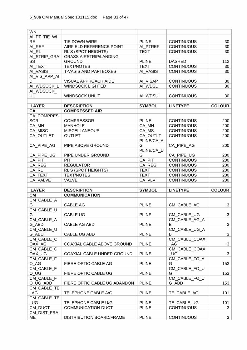
6_90a OM Manual Spec 101115.doc Page 33 of 47
WN AI_PT_TIE_WIRE TIE DOWN WIRE PLINE CONTINUOUS 30AI_REF AIRFIELD REFERENCE POINT AI_PTREF CONTINUOUS 30AI_RL RL'S (SPOT HEIGHTS) TEXT CONTINUOUS 30AI_STRIP_GRASS
GRASS AIRSTRIP/LANDING GROUND PLINE DASHED 112
AI_TEXT TEXT/NOTES TEXT CONTINUOUS 30AI_VASIS T-VASIS AND PAPI BOXES AI_VASIS CONTINUOUS 30AI_VIS_APP_AID VISUAL APPROACH AIDE AI_VISAP CONTINUOUS 30AI_WDSOCK_L WINDSOCK LIGHTED AI_WDSL CONTINUOUS 30AI_WDSOCK_UL WINDSOCK UNLIT AI_WDSU CONTINUOUS 30 LAYER DESCRIPTION SYMBOL LINETYPE COLOURCA COMPRESSED AIR CA_COMPRESSOR COMPRESSOR PLINE CONTINUOUS 200CA_MH MANHOLE CA_MH CONTINUOUS 200CA_MISC MISCELLANEOUS CA_MS CONTINUOUS 200CA_OUTLET OUTLET CA_OUTLT CONTINUOUS 200
CA_PIPE_AG PIPE ABOVE GROUND PLINE/CA_AG CA_PIPE_AG 200
CA_PIPE_UG PIPE UNDER GROUND PLINE/CA_UG CA_PIPE_UG 200
CA_PIT PIT CA_PIT CONTINUOUS 200CA_REG REGULATOR CA_REG CONTINUOUS 200CA_RL RL'S (SPOT HEIGHTS) TEXT CONTINUOUS 200CA_TEXT TEXT/NOTES TEXT CONTINUOUS 200CA_VALVE VALVE CA_VLV CONTINUOUS 200 LAYER DESCRIPTION SYMBOL LINETYPE COLOURCM COMMUNICATION CM_CABLE_AG CABLE AG PLINE CM_CABLE_AG 3CM_CABLE_UG CABLE UG PLINE CM_CABLE_UG 3CM_CABLE_AG_ABD CABLE AG ABD PLINE
CM_CABLE_AG_AB 3
CM_CABLE_UG_ABD CABLE UG ABD PLINE
CM_CABLE_UG_AB 3
CM_CABLE_COAX_AG COAXIAL CABLE ABOVE GROUND PLINE
CM_CABLE_COAX_AG 3
CM_CABLE_COAX_UG COAXIAL CABLE UNDER GROUND PLINE
CM_CABLE_COAX_UG 3
CM_CABLE_FO_AG FIBRE OPTIC CABLE AG PLINE
CM_CABLE_FO_AG 153
CM_CABLE_FO_UG FIBRE OPTIC CABLE UG PLINE
CM_CABLE_FO_UG 153
CM_CABLE_FO_UG_ABD FIBRE OPTIC CABLE UG ABANDON PLINE
CM_CABLE_FO_UG_ABD 153
CM_CABLE_TE_AG TELEPHONE CABLE A/G PLINE TE_CABLE_AG 101CM_CABLE_TE_UG TELEPHONE CABLE U/G PLINE TE_CABLE_UG 101CM_DUCT COMMUNICATION DUCT PLINE CONTINUOUS 3CM_DIST_FRAME DISTRIBUTION BOARD/FRAME PLINE CONTINUOUS 3

6_90a OM Manual Spec 101115.doc Page 34 of 47
CM_EARTH_MAT EARTH MAT CM_EARTH CONTINUOUS 3CM_EARTH_STAKE EARTH STAKE CM_ERSTK CONTINUOUS 3CM_JUNC_BOX_PIT JUNCTION BOX/PIT CM_PIT CONTINUOUS 3CM_MARKER_CABLE CABLE MARKER CM_MK CONTINUOUS 3CM_MH MANHOLE CM_MH CONTINUOUS 3CM_MISC MISCELLANEOUS CM_MS CONTINUOUS 3CM_PILLAR PILLAR CM_PILL CONTINUOUS 3CM_POLE POLE CM_POLE CONTINUOUS 3CM_PUBLIC_PHONE PUBLIC TELEPHONE CM_PHONE CONTINUOUS 3CM_RL RL'S (SPOT HEIGHTS) TEXT CONTINUOUS 3CM_SAT_DISH SATELLITE DISH CM_SDISH CONTINUOUS 3CM_TERM_BOX CABLE TERMINATION BOX CM_TRMBX CONTINUOUS 3CM_TEXT TEXT/NOTES TEXT CONTINUOUS 3 LAYER DESCRIPTION SYMBOL LINETYPE COLOURDR DRAINAGE DR_AGDRAIN AGRICULTURAL UG PLINE DASHED 5DR_COV_LINED COVERED LINED DRAIN PLINE CONTINUOUS 5DR_CULVERT CULVERT PLINE CONTINUOUS 5DR_DNPIPE DOWNPIPE DR_DPDRN CONTINUOUS 5DR_GRATED_LINED GRATED LINED DRAIN PLINE PHANTOM/HATCH 5DR_GUTTER GUTTER PLINE CONTINUOUS 5DR_HEADWALL HEADWALL
PLINE/DR_HEDWL CONTINUOUS 5
DR_INSP_OP INSPECTION OPENING DR_IO CONTINUOUS 5DR_KERB_OUTLET KERB OUTLET DR_KO CONTINUOUS 5DR_MH MANHOLE DR_MH CONTINUOUS 5DR_MISC MISCELLANEOUS DR_MS CONTINUOUS 5DR_OP_LINED OPEN LINED DRAIN PLINE CONTINUOUS 5DR_OP_UNLINED OPEN UNLINED DRAIN PLINE DR_SURFACE 5
DR_PIPE_AG PIPE ABOVE GROUND PLINE/DR_AG DR_PIPE_AG 5
DR_PIPE_AG_ABD
ABANDONED PIPE ABOVE GROUND PLINE DR_PIPE_AG_AB 5
DR_PIPE_UG PIPE UNDER GROUND PLINE/DR_UG DR_PIPE_UG 5
DR_PIPE_UG_ABD
ABANDONED PIPE UNDER GROUND PLINE DR_PIPE_UG_AB 5
DR_PT_TERM TERMINATION POINT DR_PTTRM CONTINUOUS 5DR_PUMP_SW STORMWATER PUMP DR_PMPSW CONTINUOUS 5DR_RL RL'S (SPOT HEIGHTS) TEXT CONTINUOUS 5DR_SUB_SURFACE SUB SURFACE DRAIN PLINE
DR_SUB_SURFACE 5
DR_SUMP SUMP DR_SUMPS CONTINUOUS 5DR_SUMP_DOUBLE SUMP SIDE ENTRY – DOUBLE DR_SUMPD CONTINUOUS 5DR_SUMP_GRATED SUMP GRATED (Hatch scale 2.5)
DR_GRATE/HATCH CONTINUOUS 5
DR_SUMP_MU SUMP SIDE ENTRY – MULTI DR_SUMPM CONTINUOUS 5

6_90a OM Manual Spec 101115.doc Page 35 of 47
LT DR_SUMP_SINGLE SUMP SIDE ENTRY – SINGLE DR_SUMPS CONTINUOUS 5DR_SURFACE SURFACE DRAIN PLINE DR_SURFACE 5DR_TEXT TEXT/NOTES TEXT CONTINUOUS 5DR_TRAP_DISCON TRAP DISCONNECTOR DR_TRPDI CONTINUOUS 5DR_TRAP_FLAME FLAME TRAP DR_TRPFL CONTINUOUS 5DR_TRAP_GREASE TRAP GREASE DR_TRPGR CONTINUOUS 5DR_TRAP_GROSS_INT TRAP GROSS INTERCEPTOR DR_TRPGI CONTINUOUS 5DR_TRAP_GULLY TRAP GULLY DR_TRPGU CONTINUOUS 5DR_TRAP_INTERCEPT TRAP INTERCEPTOR DR_TRPIN CONTINUOUS 5 LAYER DESCRIPTION SYMBOL LINETYPE COLOUREL ELECTRICITY
EL_CABLE_AG CABLE ABOVE GROUND PLINE/EL_AG EL_CABLE_AG 1
EL_CABLE_AG_ABD
ABANDONED CABLE ABOVE GROUND PLINE EL_CABLE_AG_AB 1
EL_CABLE_BOX_PILL CABLE BOX / PILLAR EL_PILL CONTINUOUS 1EL_CABLE_HV_AG
HIGH VOLTAGE CABLE ABOVE GROUND PLINE EL_CABLE_HV_AG 242
EL_CABLE_HV_UG
HIGH VOLTAGE CABLE UNDER GROUND PLINE EL_CABLE_HV_UG 242
EL_CABLE_LV_AG
LOW VOLTAGE CABLE ABOVE GROUND PLINE EL_CABLE_LV_AG 1
EL_CABLE_LV_UG
LOW VOLTAGE CABLE UNDER GROUND PLINE EL_CABLE_LV_UG 1
EL_CABLE_UG CABLE UNDER GROUND PLINE/EL_UG EL_CABLE_UG 1
EL_CABLE_UG_ABD
ABANDONED CABLE UNDER GROUND PLINE EL_CABLE_UG_AB 1
EL_CIRCT_HV HIGH VOLTAGE CIRCUITS EL_CIRHV CONTINUOUS 242EL_CIRCT_LV LOW VOLTAGE CIRCUITS EL_CIRLV CONTINUOUS 1EL_EARTH_HV HIGH VOLTAGE EARTH GRID PLINE CENTER 242EL_EARTH_STAKE EARTH STAKE EL_EARTH CONTINUOUS 1EL_GENERATOR ELECTRICITY GENERATOR PLINE CONTINUOUS 1EL_LIGHT GENERAL LIGHTS EL_LI CONTINUOUS 1EL_LIGHT_FLOOD FLOOD LIGHT EL_LIFLD CONTINUOUS 1EL_LIGHT_PEDESTAL LIGHT PEDESTAL EL_LIPDT CONTINUOUS 1EL_LIGHT_POLE LIGHT POLE EL_LIPOL CONTINUOUS 1EL_MARKER_CABLE CABLE MARKER EL_MK CONTINUOUS 1EL_MH MANHOLE EL_MH CONTINUOUS 1EL_MH_HV HIGH VOLTAGE MANHOLE EL_MH_HT CONTINUOUS 242EL_MISC MISCELLANEOUS EL_MS CONTINUOUS 1EL_OUTLET OUTLET EL_OUTLT CONTINUOUS 1EL_PILLAR_LV LOW VOLTAGE PILLAR EL_PILLV CONTINUOUS 1

6_90a OM Manual Spec 101115.doc Page 36 of 47
EL_PIT_HV HIGH VOLTAGE PIT AND MANHOLE EL_PITHV CONTINUOUS 242EL_PIT_LV LOW VOLTAGE PIT AND MANHOLE EL_PITLV CONTINUOUS 1EL_POLE POLE EL_POLE CONTINUOUS 1EL_POLE_HV HIGH VOLTAGE POLE EL_POLHV CONTINUOUS 242EL_POLE_LV LOW VOLTAGE POLE EL_POLLV CONTINUOUS 1EL_POLE_W_LIGHT POLE WITH LIGHT EL_PLWLI CONTINUOUS 1EL_POWER_FUSE_BRD POWER/FUSE BOARD EL_F_BOX CONTINUOUS 1EL_RL RL'S (SPOT HEIGHTS) TEXT CONTINUOUS 1EL_SUBSTN_AG SUBSTATION ABOVE GROUND EL_SUBST CONTINUOUS 1EL_SUBSTN_HV HIGH VOLTAGE SUBSTATION EL_SUBHT CONTINUOUS 242EL_SUBSTN_OH SUBSTATION OVERHEAD EL_SUBOH CONTINUOUS 1EL_SUBSTN_UG SUBSTATION UNDER GROUND
PLINE/EL_SUBST DASHED 1
EL_SWBRD SWITCHBOARD EL_SWBRD CONTINUOUS 1EL_TEXT TEXT/NOTES TEXT CONTINUOUS 1EL_TEXT_HV HIGH VOLTAGE TEXT/NOTES TEXT CONTINUOUS 242EL_TEXT_LV LOW VOLTAGE TEXT/NOTES TEXT CONTINUOUS 1EL_TOWER TOWER EL_TOWER CONTINUOUS 1EL_TRANSF_OH TRANSFORMER OVERHEAD EL_TRANS CONTINUOUS 1EL_TRANSF_OH_2P
TRANSFORMER OVERHEAD 2 POST EL_TRN2P CONTINUOUS 1
EL_TRANSF_ON_GRND TRANSFORMER ON GROUND EL_TRANS CONTINUOUS 1 LAYER DESCRIPTION SYMBOL LINETYPE COLOURFI FIRE CONTROL FI_ALARM ALARMS FI_ALARM CONTINUOUS 231FI_CABLE_AG CABLE ABOVE GROUND PLINE FI_CABLE_AG 231FI_CABLE_UG CABLE UNDER GROUND PLINE FI_CABLE_UG 231FI_CIRCT FIRE CIRCUIT FI_CIRCT CONTINUOUS 231FI_DETECT DETECTORS FI_DETCR CONTINUOUS 231FI_EXTINGUISH EXTINGUISHERS FI_EXTSR CONTINUOUS 231FI_FOAM_SUPPLY FOAM SUPPLY PIPES PLINE FI_FOAM 231FI_FOAM_TANK FOAM STORAGE TANK PLINE CONTINUOUS 235FI_FOAM_WASTE FOAM WASTE PIPES PLINE FI_FOAM 235FI_JUNC_BOX_PIT JUNCTION BOX/PIT FI_PITBX CONTINUOUS 231FI_MARKER_CABLE CABLE MARKER FI_MK CONTINUOUS 231FI_MISC MISCELLANEOUS FI_MS CONTINUOUS 231FI_PILLAR CONTROL PILLAR FI_PILL CONTINUOUS 231FI_REEL HOSE BOX REEL FI_REEL CONTINUOUS 231FI_RL RL'S (SPOT HEIGHTS) TEXT CONTINUOUS 231FI_TEXT TEXT/NOTES TEXT CONTINUOUS 231 LAYER DESCRIPTION SYMBOL LINETYPE COLOURFU FUEL FU_CABLE_CO CABLE CONTROL ABOVE GROUND PLINE FU_CABLE_CON_ 6

6_90a OM Manual Spec 101115.doc Page 37 of 47
N_AG AG FU_CABLE_CON_UG CABLE CONTROL UNDER GROUND PLINE
FU_CABLE_CON_UG 6
FU_DIP_STICK DIP STICK FU_DPSTK CONTINUOUS 6FU_EMERG_STOP EMERGENCY STOP SWITCH FU_EMSW CONTINUOUS 6FU_HYDRANT HYDRANT FU_HYD CONTINUOUS 6FU_LABEL LABELS/IDENTIFICATION TEXT CONTINUOUS 6FU_MISC MISCELLANEOUS FU_MS CONTINUOUS 6FU_PIPE_AG PIPE ABOVE GROUND PLINE FU_PIPE_AG 6FU_PIPE_AG_ABD
ABANDONED PIPE ABOVE GROUND PLINE FU_PIPE_AG_AB 6
FU_PIPE_UG PIPE UNDER GROUND PLINE FU_PIPE_UG 6FU_PIPE_UG_ABD
ABANDONED PIPE UNDER GROUND PLINE FU_PIPE_UG_AB 6
FU_PIPE_VENT_AG VENT LINE ABOVE GROUND PLINE
FU_PIPE_VENT_AG 6
FU_PIPE_VENT_UG VENT LINE UNDER GROUND PLINE
FU_PIPE_VENT_UG 6
FU_PIT FUEL PIT PLINE/FU_PIT CONTINUOUS 6
FU_PT_DISP FUEL DISPENSING POINTS FU_PTDIS CONTINUOUS 6FU_PT_EARTH EARTH POINT FU_EARTH CONTINUOUS 6FU_PT_FILL FILLING POINT FU_PTFIL CONTINUOUS 6FU_PT_OFFLO FUEL OFFLOAD POINTS FU_PTOFL CONTINUOUS 6FU_PUMP_BOWSER PUMP/BOWSER FU_PMPBW CONTINUOUS 6FU_RL RL'S (SPOT HEIGHTS) TEXT CONTINUOUS 6FU_TANK_AG TANK ABOVE GROUND FU_TNKAG CONTINUOUS 6
FU_TANK_UG TANK UNDER GROUND PLINE/FU_TNKUG DASHED 6
FU_TEXT TEXT/NOTES TEXT CONTINUOUS 6FU_VALVE FUEL VALVES FU_VLV CONTINUOUS 6FU_VALVE_REFLUX REFLUX VALVE FU_VLVRF CONTINUOUS 6FU_VALVE_SCOUR SCOUR VALVE FU_VLVSR CONTINUOUS 6FU_VALVE_STOP_AG STOP VALVE ABOVE GROUND FU_VLVSA CONTINUOUS 6FU_VALVE_STOP_UG STOP VALVE UNDER GROUND FU_VLVSU CONTINUOUS 6FU_VENT VENT FU_VENT CONTINUOUS 6 LAYER DESCRIPTION SYMBOL LINETYPE COLOURGA GAS GA_BOTGS BOTTLED GAS GA_BOTLS CONTINUOUS 8GA_LABEL LABELS/IDENTIFICATION TEXT CONTINUOUS 8GA_MARKER_PAD PADDOCK MARKER GA_MKPAD CONTINUOUS 8GA_MARKER_STONE MARKER STONE GA_MKSTN CONTINUOUS 8GA_METER METER GA_METER CONTINUOUS 8GA_MISC MISCELLANEOUS GA_MS CONTINUOUS 8GA_PIPE_AG PIPE ABOVE GROUND PLINE GA_PIPE_AG 8GA_PIPE_AG_ABD
ABANDONED PIPE ABOVE GROUND PLINE GA_PIPE_AG_AB 8
GA_PIPE_UG PIPE UNDER GROUND PLINE GA_PIPE_UG 8GA_PIPE_UG_ ABANDONED PIPE UNDER PLINE GA_PIPE_UG_AB 8

6_90a OM Manual Spec 101115.doc Page 38 of 47
ABD GROUND
GA_PIT GAS PIT PLINE/GA_PIT CONTINUOUS 8
GA_PT_CATH_PROT CATHODE PROTECTION POINT GA_PTCTH CONTINUOUS 8GA_PT_ELECT_TEST ELECTROLYSIS TEST POINT GA_PTECT CONTINUOUS 8GA_REG_DIST DISTRICT REGULATOR GA_REG CONTINUOUS 8GA_RL RL'S (SPOT HEIGHTS) TEXT CONTINUOUS 8GA_TANK_LPG LPG TANK GA_TKLPG CONTINUOUS 8GA_TEXT TEXT/NOTES TEXT CONTINUOUS 8GA_VALVE_AG VALVE ABOVE GROUND GA_VLV CONTINUOUS 8GA_VALVE_UG VALVE UNDER GROUND
PLINE/GA_VLV DASHED 8
LAYER DESCRIPTION SYMBOL LINETYPE COLOUROX OXYGEN OX_MISC MISCELLANEOUS OX_MS CONTINUOUS 191OX_PIPE_AG PIPE ABOVE GROUND PLINE OX_PIPE_AG 191OX_PIPE_UG PIPE UNDER GROUND PLINE OX_PIPE_UG 191OX_RL RL'S (SPOT HEIGHTS) TEXT CONTINUOUS 191OX_TEXT TEXT/NOTES TEXT CONTINUOUS 191OX_VALVE VALVE OX_VLV CONTINUOUS 191 LAYER DESCRIPTION SYMBOL LINETYPE COLOURPR PROPERTY PR_ADJOINING_BDY ADJOINING BOUNDARY PLINE CONTINUOUS 11PR_COMM_BDY COMMONWEALTH BOUNDARY PLINE CONTINUOUS 11PR_EASEMENT_BDY EASEMENT PLINE DASHEDX2 11PR_LEASE_BDY LEASE BOUNDARY PLINE CONTINUOUS 11PR_MISC MISCELLANEOUS PR_MS CONTINUOUS 11PR_RL RL'S (SPOT HEIGHTS) TEXT CONTINUOUS 11PR_SPECIAL_BDY SPECIAL AREAS PLINE CONTINUOUS 11PR_TEXT TEXT/NOTES TEXT CONTINUOUS 11PR_TEXT_ADJOINING ADJOINING LAND TEXT/NOTES TEXT CONTINUOUS 11PR_TEXT_COMM
COMMONWEALTH LAND TEXT/NOTES TEXT CONTINUOUS 11
PR_TEXT_CT CERTIFICATE OF TITLE TEXT CONTINUOUS 11PR_TEXT_EASEMENT EASEMENT TEXT/NOTES TEXT CONTINUOUS 11PR_TEXT_LEASE LEASE TEXT/NOTES TEXT CONTINUOUS 11PR_TEXT_LOT_PLAN LOT AND PLAN NUMBER TEXT CONTINUOUS 11PR_TEXT_SPECIAL SPECIAL AREAS TEXT/NOTES PLINE CONTINUOUS 11 LAYER DESCRIPTION SYMBOL LINETYPE COLOURRA RAILWAY RA_BALLAST BALLAST RA_BALST CONTINUOUS 7RA_CROSSING CROSSING PLINE CONTINUOUS 7

6_90a OM Manual Spec 101115.doc Page 39 of 47
RA_JUNCTION JUNCTION PLINE CONTINUOUS 7RA_MISC MISCELLANEOUS RA_MS CONTINUOUS 7RA_PLATFORM PLATFORM PLINE CONTINUOUS 7RA_POINTS POINTS RA_PT CONTINUOUS 7RA_POINTS_CONTROL POINTS CONTROL RA_PTCTR CONTINUOUS 7RA_RL RL'S (SPOT HEIGHTS) TEXT CONTINUOUS 7RA_SIGNAL SIGNAL RA_SGNL CONTINUOUS 7RA_SIGNAL_CABLE SIGNAL CABLE PLINE CONTINUOUS 7RA_SIGNAL_CONTROL SIGNAL CONTROL RA_SGNLC CONTINUOUS 7RA_SLEEPER SLEEPER RA_SLPER CONTINUOUS 7RA_STAUN_M_IND STANCHION/MIND RA_STCHN CONTINUOUS 7RA_TEXT TEXT/NOTES TEXT CONTINUOUS 7RA_TRACK TRACK PLINE RA_TRACK 7RA_TRAMWAY TRAMWAY PLINE CONTINUOUS 7 LAYER DESCRIPTION SYMBOL LINETYPE COLOURRD ROAD RD_CARPARK CARPARK PLINE CONTINUOUS 7RD_CROWN CROWN PLINE CENTER 7RD_DRIVEWAY DRIVEWAY PLINE CONTINUOUS 7RD_GUIDE_POST GUIDE POST RD_GPOST CONTINUOUS 7RD_KERB KERB ONLY PLINE CONTINUOUS 7RD_KERB_BACK BACK OF KERB PLINE CONTINUOUS 7RD_KERB_CROSSING CROSSING KERB PLINE DASHED 7RD_KERB_FRONT FRONT OF KERB PLINE CONTINUOUS 7RD_KERB_INVERT INVERT OF KERB PLINE CONTINUOUS 7RD_KERB_LIP LIP OF KERB PLINE CONTINUOUS 7RD_KERB_MOUNT MOUNTABLE KERB PLINE CONTINUOUS 7RD_KERB_STD STANDARD KERB PLINE CONTINUOUS 7RD_LINE_MARKING LINE MARKING PLINE DASHED 7RD_MISC MISCELLANEOUS RD_MS CONTINUOUS 7RD_PATH PATH PLINE CONTINUOUS 7RD_PED_CROSSING PEDESTRIAN CROSSING PLINE DASHED 7RD_RAIL_BARRIER GUARDRAIL / BARRIER PLINE DASHDOT 7RD_RL RL'S (SPOT HEIGHTS) TEXT CONTINUOUS 7RD_SEALED SEALED ROAD PLINE CONTINUOUS 7RD_SHOULDER SHOULDER PLINE DASHED 7RD_SPEED_HUMP SPEED HUMP PLINE CONTINUOUS 7RD_TEXT TEXT/NOTES TEXT CONTINUOUS 7RD_TRACK TRACK PLINE DASHED 7RD_UNSEALE UNSEALED ROAD PLINE DASHED 7

6_90a OM Manual Spec 101115.doc Page 40 of 47
D LAYER DESCRIPTION SYMBOL LINETYPE COLOURSC SECURITY SC_ALARM ALARMS SC_ALARM CONTINUOUS 40SC_CABLE_AG CABLE ABOVE GROUND PLINE SC_CABLE_AG 40SC_CABLE_AG_ABD
CABLE ABOVE GROUND ABANDONED PLINE SC_CABLE_AG_AB 40
SC_CABLE_UG CABLE UNDER GROUND PLINE SC_CABLE_UG 40SC_CABLE_UG_ABD
CABLE UNDER GROUND ABANDONED PLINE
SC_CABLE_UG_AB 40
SC_CAMERA SECURITY CAMERA SC_CAM CONTINUOUS 40SC_CONTROL CONTROL UNITS SC_CTRL CONTINUOUS 40SC_DETECT DETECTORS SC_DET CONTINUOUS 40SC_LIGHT_SEC SECURITY LIGHTING SC_LISEC CONTINUOUS 40SC_LIGHT_FLOOD FLOOD LIGHT SC_LIFLD CONTINUOUS 40SC_MARKER_CABLE CABLE MARKER SC_MK CONTINUOUS 40SC_MH MANHOLE SC_MH CONTINUOUS 40SC_MISC MISCELLANEOUS SC_MS CONTINUOUS 40SC_PILLAR SECURITY PILLAR SC_PILL CONTINUOUS 40SC_POLE POLE SC_POLE CONTINUOUS 40SC_RL RL'S (SPOT HEIGHTS) TEXT CONTINUOUS 40SC_SWBRD SWITCH BOARD SC_SWBRD CONTINUOUS 40SC_TEXT TEXT/NOTES TEXT CONTINUOUS 40 LAYER DESCRIPTION SYMBOL LINETYPE COLOURSE SEWERAGE SE_CLOSET_CHEM CLOSET CHEMICAL SE_CLSCH CONTINUOUS 42SE_CLOSET_EARTH CLOSET EARTH SE_ERTCL CONTINUOUS 42SE_FLOOR_WASTE FLOOR WASTE SE_FLWST CONTINUOUS 42SE_INSP_OPEN INSPECTION OPENING SE_INSPE CONTINUOUS 42SE_MH MANHOLE SE_MH CONTINUOUS 42SE_MISC MISCELLANEOUS SE_MS CONTINUOUS 42SE_OUTFALL OUTFALL SE_OUTFL CONTINUOUS 42SE_PIPE_AG PIPE ABOVE GROUND PLINE SE_PIPE_AG 42SE_PIPE_AG_ABD
ABANDONED PIPE ABOVE GROUND PLINE SE_PIPE_AG_AB 42
SE_PIPE_RIS_MAIN_AG RISING MAIN ABOVE GROUND PLINE
SE_RISNG_MAIN_AG 64
SE_PIPE_RIS_MAIN_UG RISING MAIN UNDER GROUND PLINE
SE_RISNG_MAIN_UG 64
SE_PIPE_TRADE_AG
TRADE WASTE PIPE ABOVE GROUND PLINE
SE_PIPE_TRADE_AG 54
SE_PIPE_TRADE_UG
TRADE WASTE PIPE UNDER GROUND PLINE
SE_PIPE_TRADE_UG 54
SE_PIPE_UG PIPE UNDER GROUND PLINE SE_PIPE_UG 42SE_PIPE_UG_ABD
ABANDONED PIPE UNDER GROUND PLINE SE_PIPE_UG_AB 42
SE_PIT SEWERAGE PIT SE_PIT CONTINUOUS 42SE_PIT_ABSO ABSORPTION PIT SE_PITAB CONTINUOUS 42

6_90a OM Manual Spec 101115.doc Page 41 of 47
RP SE_POND POND PLINE DASHED 42SE_RL RL'S (SPOT HEIGHTS) TEXT CONTINUOUS 42SE_STN_PUMP_AG PUMP STATION ABOVE GROUND SE_STNPA CONTINUOUS 42SE_STN_PUMP_UG PUMP STATION UNDER GROUND SE_STNPU DASHED 42SE_TANK_SEPTIC SEPTIC TANK SE_TKSEP CONTINUOUS 42SE_TEXT TEXT/NOTES TEXT CONTINUOUS 42SE_TRADE_AG TRADE WASTE ABOVE GROUND PLINE
SE_PIPE_TRADE_AG 54
SE_TRADE_MH TRADE WASTE MANHOLE SE_MH_TW CONTINUOUS 54SE_TRADE_MISC TRADE WASTE MISCELLANEOUS SE_MS_TW CONTINUOUS 54SE_TRADE_PUMP_STN TRADE WASTE PUMP STATION SE_STNPT CONTINUOUS 54SE_TRADE_TANK_UG
TRADE WASTE TANK UNDER GROUND
PLINE/SE_TK_TW DASHED 54
SE_TRAP_BNDY_AG TRAP BOUNDARY ABOVE GROUND SE_TRPAG CONTINUOUS 42SE_TRAP_BNDY_UG
TRAP BOUNDARY UNDER GROUND
PLINE/SE_TRPUG DASHED 42
SE_TRAP_DISCON TRAP DISCONNECTOR SE_TRPDI CONTINUOUS 42SE_TRAP_GREASE TRAP GREASE SE_TRPGR CONTINUOUS 42SE_TRAP_GULLY TRAP GULLY SE_TRPGU CONTINUOUS 42SE_VENT VENT SE_VENT CONTINUOUS 42SE_VENT_PIT VENT PIT SE_PITVN CONTINUOUS 42 LAYER DESCRIPTION SYMBOL LINETYPE COLOURSM STEAM SM_APPLIANCE APPLIANCE SM_APL CONTINUOUS 181SM_BOILER BOILER SM_BOILR CONTINUOUS 181SM_MISC MISCELLANEOUS SM_MS CONTINUOUS 181SM_PIPE_AG PIPE ABOVE GROUND PLINE SM_PIPE_AG 181SM_PIPE_AG_ABD
ABANDONED PIPE ABOVE GROUND PLINE SM_PIPE_AG_AB 181
SM_PIPE_UG PIPE UNDER GROUND PLINE SM_PIPE_UG 181SM_PIPE_UG_ABD
ABANDONED PIPE UNDER GROUND PLINE SM_PIPE_UG_AB 181
SM_RL RL'S (SPOT HEIGHTS) TEXT CONTINUOUS 181SM_TEXT TEXT/NOTES TEXT CONTINUOUS 181SM_VALVE_AG VALVE ABOVE GROUND SM_VLVAG CONTINUOUS 181SM_VALVE_UG VALVE UNDER GROUND
PLINE/SM_VLVUG DASHED 181
LAYER DESCRIPTION SYMBOL LINETYPE COLOURST STRUCTURE ST_ASSET_NO ASSET NUMBER TEXT CONTINUOUS 7ST_AWNING AWNING/COVERED WAYS PLINE CONTINUOUS 7ST_BBQ BARBECUE ST_BBQ CONTINUOUS 7ST_BOLLARD BOLLARD ST_BOLRD CONTINUOUS 7ST_BRIDGE BRIDGE PLINE CONTINUOUS 7

6_90a OM Manual Spec 101115.doc Page 42 of 47
ST_BRIDGE_WEIGH WEIGH BRIDGE PLINE CONTINUOUS 7
ST_BUILDING BUILDING PLINE (0.5 WIDE) CONTINUOUS 7
ST_CARPORT CARPORT PLINE CONTINUOUS 7ST_CAUSEWAY CAUSEWAY PLINE DASHED 7ST_CBLWAY_CHR_LFT CABLEWAY / CHAIR LIFT PLINE CONTINUOUS 7ST_CHIMNEY CHIMNEY ST_CHMNY CONTINUOUS 7ST_CLOTH_HST_LINE CLOTH HOIST / LINE ST_CLOTH CONTINUOUS 7ST_COLUMN_SUPPORT COLUMN / SUPPORT
PLINE/ST_CLMSP CONTINUOUS 7
ST_CONVEY_BELT CONVEYOR BELT PLINE CONTINUOUS 7ST_CUTTING CUTTING PLINE CONTINUOUS 7ST_DATA_RCD_STN DATA RECORDING STATION ST_DATRC CONTINUOUS 7ST_DEM_BLDG DEMOLISHED BUILDING PLINE DASHED 8ST_DOCK DOCK PLINE CONTINUOUS 7ST_DUCT_AG SERVICE DUCT ABOVE GROUND PLINE ST_DUCT_AG 7ST_DUCT_UG SERVICE DUCT UNDER GROUND PLINE ST_DUCT_UG 7ST_FENCE FENCE PLINE ST_FENCE 7ST_FENCE_POST FENCE POST ST_FNCEP CONTINUOUS 7ST_FLAG_POLE FLAG POLE ST_POLFL CONTINUOUS 7ST_FORD FORD PLINE CONTINUOUS 7ST_GATE GATE ST_GATE CONTINUOUS 7ST_GATE_BOOM GATE BOOM ST_GATEB CONTINUOUS 7ST_GATE_CRASH CRASH GATE ST_GATEC CONTINUOUS 7ST_GRID_STOCK GRID STOCK ST_GRDST CONTINUOUS 7ST_GUY_WIRE GUY WIRE ST_GUYWR CONTINUOUS 7ST_HATCH SITE HATCHING HATCH HATCH PATTERN 7ST_INCINERATOR INCINERATOR ST_INCTR CONTINUOUS 7ST_LITTERBIN LITTER BIN ST_LIBIN CONTINUOUS 7ST_MAIL_BOX MAIL BOX ST_MAILB CONTINUOUS 7ST_MARKER_DUCT DUCT MARKER ST_MKDUC CONTINUOUS 7ST_MAST_LIGHT LIGHTNING MAST ST_MSTLI CONTINUOUS 7ST_MAST_PYLON MAST / PYLON ST_MSTPL CONTINUOUS 7ST_MISC MISCELLANEOUS ST_MS CONTINUOUS 7ST_MONUMENT MONUMENT ST_MONUM CONTINUOUS 7ST_NAME BUILDING NAME TEXT CONTINUOUS 7ST_OHEAD_WALKWAY OVERHEAD WALKWAY PLINE CONTINUOUS 7ST_PATIO_DECK PATIO / DECK PLINE CONTINUOUS 7ST_PAVEMENT PAVEMENT PLINE CONTINUOUS 7

6_90a OM Manual Spec 101115.doc Page 43 of 47
ST_PERGOLA PERGOLA PLINE CONTINUOUS 7ST_PLAT_PLINTH_EDGE
PLATFORM, PLINTH AND EDGE OF CONCRETE PLINE DASHED 7
ST_PLAYGROUND PLAYGROUND PLINE CONTINUOUS 7ST_POLE POLE/POST CIRCLE CONTINUOUS 7ST_RACK RACK PLINE CONTINUOUS 7ST_RAILING RAILING ST_RAILING ST_RAILING 7ST_RAMP RAMP PLINE CONTINUOUS 7ST_RL RL'S (SPOT HEIGHTS) TEXT CONTINUOUS 7ST_ROOFLINE_EAVES ROOF LINE / EAVES PLINE DASHED 7ST_RUINS RUINS PLINE CONTINUOUS 7ST_SCREEN_ACCOUSTIC SOUND BARRIER SCREENS PLINE ST_WALL 7ST_SEAT SEAT ST_SEAT CONTINUOUS 7ST_SHED SHED PLINE CONTINUOUS 7ST_SIGN HOARDING / SIGN ST_SIGNH CONTINUOUS 7ST_SILO SILO ST_SILO CONTINUOUS 7ST_SLIPWAY SLIPWAY PLINE DASHED 7ST_SOLAR_ABSORBER SOLAR ABSORBER PANEL ST_SOLAB CONTINUOUS 7ST_SPORT_FACILITY SPORT FACILITY PLINE CONTINUOUS 83ST_STEPS STEPS PLINE CONTINUOUS 7ST_STOCKYARD_YARD STOCKYARD/YARD PLINE CONTINUOUS 7ST_SWIM_POOL SWIMMING POOL PLINE CONTINUOUS 121ST_TEXT TEXT/NOTES TEXT CONTINUOUS 7ST_TIDE_GAUGE TIDE GAUGE ST_TIDGA CONTINUOUS 7ST_TOWER TOWER/AERIAL ST_TOWER CONTINUOUS 7ST_UNDERPASS UNDERPASS PLINE DASHED 7ST_VERANDAH VERANDAH PLINE CONTINUOUS 7ST_WALL WALL PLINE ST_WALL 7ST_WALL_DAM DAM WALL PLINE CONTINUOUS 7ST_WALL_RET RETAINING WALL PLINE ST_WALL_RET 7ST_WEIR WEIR PLINE CONTINUOUS 7ST_WHARF WHARF PLINE CONTINUOUS 7ST_WINDMILL WINDMILL ST_WINDM CONTINUOUS 7 LAYER DESCRIPTION SYMBOL LINETYPE COLOURSU SURVEY SU_BENCHMARK SURVEY BENCHMARK SU_BNCMK CONTINUOUS 1SU_CONC_BLOCK SURVEY CONCRETE BLOCK SU_CNCBL CONTINUOUS 1SU_COOR_REF_MARK COORDINATED REFERENCE MAR SU_CRFMK CONTINUOUS 1SU_DHW DRILLHOLE/DRILLHOLE AND WING SU_DHW CONTINUOUS 1SU_MISC SURVEY MISCELLANEOUS SU_MS CONTINUOUS 1SU_PEG SURVEY PEG POST SU_PEG CONTINUOUS 1SU_PILLAR SURVEY PILLAR SU_PILL CONTINUOUS 1SU_PIPE SPIKE/PIN/PIPE SU_PIPE CONTINUOUS 1

6_90a OM Manual Spec 101115.doc Page 44 of 47
SU_PSM PERMANENT SURVEY MARK SU_PSM CONTINUOUS 1SU_RL RL'S (SPOT HEIGHTS) TEXT CONTINUOUS 1SU_STEEL_ROD SURVEY STEEL ROD SU_STLRD CONTINUOUS 1SU_TEXT SURVEY TEXT TEXT CONTINUOUS 1SU_TRIG_STN TRIG STATION SU_TRIG CONTINUOUS 1 LAYER DESCRIPTION SYMBOL LINETYPE COLOURTO TOPOGRAPHIC TO_BANK_BOTTOM BANK BOTTOM PLINE DAHED 8TO_BANK_TOP BANK TOP PLINE TO_BANK_TOP_2 8TO_CLIFF_BOTTOM CLIFF BOTTOM PLINE DASHED 8TO_CLIFF_TOP CLIFF TOP PLINE CONTINUOUS 8TO_CONT_MAJ
PRIMARY CONTOURS 1M INTERVALS PLINE CONTINUOUS 44
TO_CONT_MIN SECONDARY CONTOURS PLINE CONTINUOUS 43TO_CUTTING CUTTING PLINE TO_CUTTING_2 8TO_DEPRESSION DEPRESSION PLINE DASHED 8TO_EDGING GARDEN EDGING PLINE CONTINUOUS 8TO_EMBANKMENT EMBANKMENT PLINE
TO_EMBANKMENT_2 8
TO_FILL FILL AREA PLINE DASHED 8TO_GOLF_FAIRWAY GOLF FAIRWAY PLINE DASHED 3TO_LEVEE_BANK LEVEE BANK PLINE DASHED 8TO_MISC MISCELLANEOUS TO_MS CONTINUOUS 8TO_NAT_SURFACE NATURAL SURFACE TO_NATSF CONTINUOUS 8TO_OVAL SPORTS OVAL LINE PLINE CONTINUOUS 8TO_QUARRY_SOIL_PIT QUARRY / SOIL PIT PLINE DASHED 8TO_RL RL'S (SPOT HEIGHTS) TEXT CONTINUOUS 8TO_ROCK ROCK PLINE HIDDEN 8TO_SANDHILL_DUNE SANDHILL / DUNE PLINE DOT 8TO_STOCKPILE STOCKPILE PLINE DASHED 8TO_TBOUND LAND TITLE BOUNDARIES PLINE CONTINUOUS 8TO_TEXT TEXT/NOTES TEXT CONTINUOUS 8 LAYER DESCRIPTION SYMBOL LINETYPE COLOURTR TRAFFIC
TR_CABLE_AG LIGHT CONTROL CABLE ABOVE GROUND PLINE TR_CABLE_AG 30
TR_CABLE_UG LIGHT CONTROL CABLE UNDER GROUND PLINE TR_CABLE_UG 30
TR_CONTROL_BOX LIGHT CONTROL BOX TR_CNTLB CONTINUOUS 30TR_LIGHT LIGHT TR_LIGHT CONTINUOUS 30TR_MIRROR TRAFFIC MIRROR TR_MIROR CONTINUOUS 30TR_MISC MISCELLANEOUS TR_MS CONTINUOUS 0TR_PARK_METER PARKING METER TR_METER CONTINUOUS 30

6_90a OM Manual Spec 101115.doc Page 45 of 47
TR_PARK_SIGN PARKING SIGN TR_PARKS CONTINUOUS 30TR_PARK_TICK_DISP PARKING TICKET DISPENSER TR_TCKTD CONTINUOUS 30TR_RL RL'S (SPOT HEIGHTS) TEXT CONTINUOUS 30TR_SENSOR TRAFFIC SENSOR TR_SENSR CONTINUOUS 30TR_SIGN TRAFFIC SIGN TR_SIGN CONTINUOUS 30TR_ST_NAME_SIGN STREET NAME SIGN TR_STRTS CONTINUOUS 30TR_TEXT TEXT/NOTES TEXT CONTINUOUS 30 LAYER DESCRIPTION SYMBOL LINETYPE COLOURUN UNKNOWN UN_LINE_AG PIPE/LINE ABOVE GROUND PLINE UN_LINE_AG 40UN_LINE_UG PIPE/LINE UNDER GROUND PLINE UN_LINE_UG 40UN_MH MANHOLE UN_MH CONTINUOUS 40UN_MISC MISCELLANEOUS UN_MS CONTINUOUS 40UN_PILLAR PILLAR UN_PILL CONTINUOUS 40
UN_PIT PIT PLINE/UN_PIT DASHED 40
UN_POLE POLE UN_POLE CONTINUOUS 40UN_PUMP PUMP UN_PMP CONTINUOUS 40UN_RL RL'S (SPOT HEIGHTS) TEXT CONTINUOUS 40UN_TEXT TEXT/NOTES TEXT CONTINUOUS 40UN_TRAP TRAP UN_TRAP CONTINUOUS 40UN_VALVE VALVE UN_VLV CONTINUOUS 40UN_VENT VENT UN_VENT CONTINUOUS 40 LAYER DESCRIPTION SYMBOL LINETYPE COLOURVE VEGETATION VE_CULTIVATION CULTIVATION PLINE CONTINUOUS 103VE_FLOWER_BOX FLOWER BOX PLINE CONTINUOUS 103VE_GARDEN_BED GARDEN BED PLINE CONTINUOUS 103VE_HEDGE HEDGE PLINE VE_HEDGE 103VE_LAWN LAWN PLINE CONTINUOUS 103VE_MISC MISCELLANEOUS VE_MS CONTINUOUS 103VE_PLANTATION PLANTATION PLINE CONTINUOUS 103VE_RL RL'S (SPOT HEIGHTS) TEXT CONTINUOUS 103VE_SAPLING SAPLING VE_SAPLG CONTINUOUS 103VE_SCRUB SCRUB PLINE CONTINUOUS 103VE_SHRUB SHRUB VE_SHRUB CONTINUOUS 103VE_STUMP STUMP VE_STUMP CONTINUOUS 103VE_TEXT TEXT/NOTES TEXT CONTINUOUS 103VE_TREE TREE VE_TREE CONTINUOUS 103VE_TREE_MULT TREE MULTI TRUNK VE_TREEM CONTINUOUS 103 LAYER DESCRIPTION SYMBOL LINETYPE COLOURWF WATER FEATURES WF_BOT_BANK BOTTOM BANK WATER COURSE PLINE WF_DASH_3 141WF_DAM DAM PLINE DASHED 141WF_HWM HIGH WATER MARK WF_HWM DASHED 141WF_IRR_CHAN IRRIGATION CHANNEL PLINE PHANTOM 141

6_90a OM Manual Spec 101115.doc Page 46 of 47
NEL WF_LAKE LAKE PLINE CONTINUOUS 141WF_LWM LOW WATER MARK WF_LWM DASHED 141WF_MISC MISCELLANEOUS WF_MS CONTINUOUS 141WF_RL RL'S (SPOT HEIGHTS) TEXT CONTINUOUS 141WF_SWAMP SWAMP PLINE DASHED 141WF_TEXT TEXT/NOTES TEXT CONTINUOUS 141WF_TOP_BANK TOP BANK WATER COURSE PLINE
WF_BNK_TOP_CORS 141
WF_WATER_LEVEL WATER LEVEL WF_WLVL CONTINUOUS 141WF_WATERCOURSE WATER COURSE PLINE
WF_WATERCOURSE 141
LAYER DESCRIPTION SYMBOL LINETYPE COLOURWS WATER SUPPLY WS_BORE_WELL BORE / WELL WS_BORE CONTINUOUS 4WS_CAP_END END CAP WS_CAPEA CONTINUOUS 4WS_FOUNTAIN_DRINK DRINK FOUNTAIN WS_DRNKF CONTINUOUS 4WS_HOSE_BOX_REEL HOSE BOX / REEL WS_HOSEB CONTINUOUS 4WS_HW_TANK HOT WATER TANK HW_TANK C 4WS_HYD_BOOSTER HYDRANT BOOSTER WS)HYBS C 4WS_HYD_GROUND HYDRANT GROUND WS_HYDRT CONTINUOUS 4WS_HYD_PILLAR HYDRANT PILLAR WS_HYDRT CONTINUOUS 4WS_IR_CONTROL CONTROL UNITS IR_CTRUN CONTINUOUS 121WS_IR_LABEL LABELS/IDENTIFICATION TEXT CONTINUOUS 121WS_IR_MISC MISCELLANEOUS IR_MS CONTINUOUS 121WS_IR_PIPE_AG PIPE ABOVE GROUND PLINE IR_PIPE_AG 121WS_IR_PIPE_UG PIPE UNDER GROUND PLINE IR_PIPE_UG 121WS_IR_PIPE_EF_AG EFFLUENT PIPE A/G PLINE EF_PIPE_AG 140WS_IR_PIPE_EF_UG EFFLUENTPIPE U/G PLINE EF_PIPE_UG 140WS_IR_RL RL'S (SPOT HEIGHTS) TEXT CONTINUOUS 121WS_IR_SPRINK_COVER SPRINKLER COVERAGE (RANGE) PLINE DASHEDX2 121WS_IR_SPRINKLER SPRINKLER IR_SPRKL CONTINUOUS 121WS_IR_VALVE_SOL SOLENOID VALVE IR_SOL CONTINUOUS 121WS_MARKER WATER MARKER WS_MK CONTINUOUS 4WS_MARKER_HYD HYDRANT MARKER WS_MKHYD CONTINUOUS 4WS_METER WATER METER WS_METER CONTINUOUS 4WS_MH MANHOLE WS_MH CONTINUOUS 4WS_MISC MISCELLANEOUS WS_MS CONTINUOUS 4WS_PIPE_AG PIPE ABOVE GROUND PLINE WS_PIPE_AG 4WS_PIPE_AG_ABD
ABANDONED PIPE UNDER GROUND PLINE WS_PIPE_AG_AB 4
WS_PIPE_DEM DEMINERALISED WATER SUPPLY PLINE WS_PIPE_UG 151

6_90a OM Manual Spec 101115.doc Page 47 of 47
INERALISED PIPE WS_PIPE_FIRE
WATER SUPPLY PIPE FOR FIRE SERVICES PLINE WS_PIPE_UG 140
WS_PIPE_PUMP
WATER SUPPLY PIPE FROM BORE/PUMP PLINE WS_PIPE_UG 4
WS_PIPE_UG PIPE UNDER GROUND PLINE WS_PIPE_UG 4WS_PIPE_UG_ABD
ABANDONED PIPE UNDER GROUND PLINE WS_PIPE_UG_AB 4
WS_PIT PIT WS_PIT CONTINUOUS 4WS_RL RL'S (SPOT HEIGHTS) TEXT CONTINUOUS 4WS_STANDPIPE STANDPIPE WS_STNDP CONTINUOUS 4WS_STN_PUMP PUMP STATION WS_STNPM CONTINUOUS 4WS_STOP_COCK STOP COCK WS_STOPC CONTINUOUS 4WS_TANK_AG TANK ABOVE GROUND WS_TKAG CONTINUOUS 4
WS_TANK_UG TANK UNDER GROUND PLINE/WS_TKUG DASHED 4
WS_TAP TAP WS_TAP CONTINUOUS 4WS_TEXT TEXT/NOTES TEXT CONTINUOUS 4
WS_TROUGH TROUGH PLINE/WS_TROGH CONTINUOUS 4
WS_VALVE_AIR AIR VALVE WS_VLVAR CONTINUOUS 4WS_VALVE_BACKFLOW BACKFLOW VALVE WS_VLVBF CONTINUOUS 4WS_VALVE_REFLUX REFLUX VALVE WS_VLVRF CONTINUOUS 4WS_VALVE_SCOUR SCOUR VALVE WS_VLVSR CONTINUOUS 4WS_VALVE_STOP STOP / SLUICE VALVE WS_VLVST CONTINUOUS 4WS_VALVE_STOP_PIT STOP VALVE PIT WS_PIT CONTINUOUS 4


![101115 Practical Radio Application Final[1]](https://img.pdfslide.us/doc/110x75/577cdef91a28ab9e78b03501/101115-practical-radio-application-final1.jpg)