Embed Size (px)
Citation preview
Engine and peripherals
77 11 322 222
"The repair procedures given by the manufacturer in this document are based on the technical specifications current when it was prepared.
The methods may be modified as a result of changes introduced by the manufacturer in the production of the various component units and accessories from which his vehicles are constructed."
MARCH 2006
All rights reserved by Renault s.a.s.
Edition anglaise
Copying or translating, in part or in full, of this document or use of the service part reference numbering system is forbidden without the prior written authority of Renault s.a.s.
© Renault s.a.s. 2006
DIESEL INJECTION
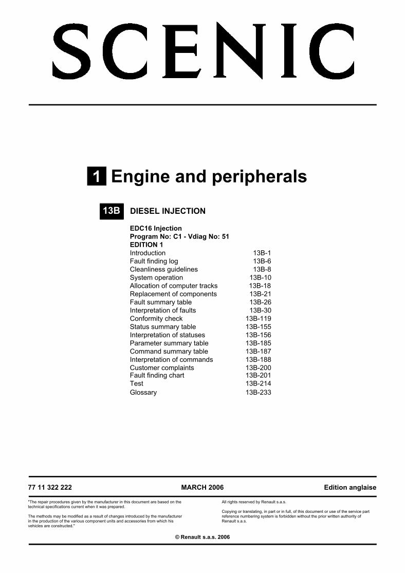
EDC16 InjectionProgram No: C1 - Vdiag No: 51EDITION 1Introduction 13B-1Fault finding log 13B-6Cleanliness guidelines 13B-8System operation 13B-10Allocation of computer tracks 13B-18Replacement of components 13B-21Fault summary table 13B-26Interpretation of faults 13B-30Conformity check 13B-119Status summary table 13B-155Interpretation of statuses 13B-156Parameter summary table 13B-185Command summary table 13B-187Interpretation of commands 13B-188Customer complaints 13B-200Fault finding chart 13B-201Test 13B-214Glossary 13B-233
13B
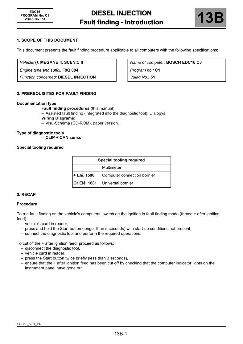
DIESEL INJECTIONFault finding - Introduction 13B
13B-1
113BEDC16
PROGRAM No: C1Vdiag No.: 51
DIESEL INJECTIONFault finding - Introduction
1. SCOPE OF THIS DOCUMENT
This document presents the fault finding procedure applicable to all computers with the following specifications:
2. PREREQUISITES FOR FAULT FINDING
Documentation typeFault finding procedures (this manual):– Assisted fault finding (integrated into the diagnostic tool), Dialogys.Wiring Diagrams:– Visu-Schéma (CD-ROM), paper version.
Type of diagnostic tools– CLIP + CAN sensor
Special tooling required
3. RECAP
Procedure
To run fault finding on the vehicle's computers, switch on the ignition in fault finding mode (forced + after ignition feed).
– vehicle's card in reader;– press and hold the Start button (longer than 5 seconds) with start-up conditions not present,– connect the diagnostic tool and perform the required operations.
To cut off the + after ignition feed, proceed as follows:– disconnect the diagnostic tool,– vehicle card in reader,– press the Start button twice briefly (less than 3 seconds),– ensure that the + after ignition feed has been cut off by checking that the computer indicator lights on the
instrument panel have gone out.
Vehicle(s): MEGANE II, SCENIC II
Engine type and suffix: F9Q 804
Function concerned: DIESEL INJECTION
Name of computer: BOSCH EDC16 C3
Program no.: C1
Vdiag No.: 51
Special tooling required
Multimeter
+ Elé. 1590 Computer connection bornier
Or Elé. 1681 Universal bornier
EDC16_V51_PRELI
DIESEL INJECTIONFault finding - Introduction 13B
13B-2
EDC16PROGRAM No: C1
Vdiag No.: 51
Faults
Faults are declared as either present or stored (depending on whether they appeared in a certain context and have disappeared since, or whether they remain present but have not been diagnosed within the current context).
The present or stored status of faults should be taken into consideration when the diagnostic tool is switched on after the + after ignition feed (without any system components being active).
For a present fault, apply the procedure described in the Interpretation of faults section.
For a stored fault, note the faults displayed and apply the instructions in the Notes section.
If the fault is confirmed when the instructions in the Notes section are applied, the fault is present. Deal with the fault
If the fault is not confirmed, check:– the electrical lines which correspond to the fault,– the connectors for these lines (for oxidation, bent pins, etc.),– the resistance of the component detected as faulty,– the condition of the wires (melted or split insulation, wear).
Conformity check
The aim of the conformity check is to check data that does not produce a fault on the diagnostic tool because the data is inconsistent. Therefore, this stage is used to:
– carry out fault finding on faults that do not have a fault display, and which may correspond to a customer complaint.
– check that the system is operating correctly and that there is no risk of a fault recurring after repairs.
This section gives the fault finding procedures for statuses and parameters and the conditions for checking them.
If a status is not behaving normally or a parameter is outside the permitted tolerance values, consult the corresponding fault finding page.
Customer complaints - Fault finding chart
If the test with the diagnostic tool is OK but the customer complaint is still present, the fault should be processed by customer complaints.
A synopsis of the general procedure to follow is provided on the following page in the form of a flow chart
DIESEL INJECTIONFault finding - Introduction 13B
13B-3
EDC16PROGRAM No: C1
Vdiag No.: 51
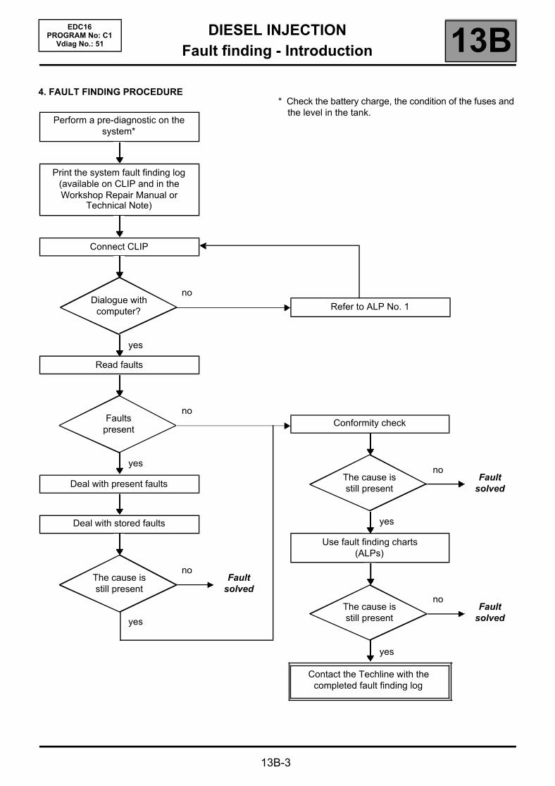
4. FAULT FINDING PROCEDURE
Perform a pre-diagnostic on the system*
Print the system fault finding log (available on CLIP and in the Workshop Repair Manual or
Technical Note)
Connect CLIP
noDialogue with
computer?
yes
Read faults
noFaults
present
yes
Deal with present faults
Deal with stored faults
noThe cause is still present
Fault solved
yes
Refer to ALP No. 1
Conformity check
noThe cause is still present
Fault solved
yes
Use fault finding charts (ALPs)
noThe cause is still present
Fault solved
yes
Contact the Techline with the completed fault finding log
* Check the battery charge, the condition of the fuses and the level in the tank.

DIESEL INJECTIONFault finding - Introduction 13B
13B-4
EDC16PROGRAM No: C1
Vdiag No.: 51
FAULT FINDING PROCEDURE (continued)
Wiring check
Fault finding problemsDisconnecting the connectors and/or manipulating the wiring harness may temporarily remove the cause of a fault.Electrical measurements of voltage, resistance and insulation are generally correct, especially if the fault is not present when the analysis is made (stored fault).
Visual inspectionLook for damage under the bonnet and in the passenger compartment.Carefully check the fuses, insulators and wiring harness routing.Look for signs of oxidation.
Tactile inspectionWhile manipulating the wiring harness, use the diagnostic tool to note any change in fault status from stored to present.Make sure that the connectors are properly locked.Apply light pressure to the connectors.Twist the wiring harness.If there is a change in status, try to locate the source of the fault.
Inspection of each componentDisconnect the connectors and check the appearance of the clips and tabs, as well as the crimping (no crimping on the insulating section).Make sure that the clips and tabs are properly locked in the sockets.Check that no clips or tabs have been dislodged during connection.Check the clip contact pressure using an appropriate model of tab.
Resistance checkCheck the continuity of entire lines, then section by section.Look for a short circuit to earth, to + 12 V or to another wire.
If a fault is detected, repair or replace the wiring harness.
DIESEL INJECTIONFault finding - Introduction 13B
13B-5
EDC16PROGRAM No: C1
Vdiag No.: 51
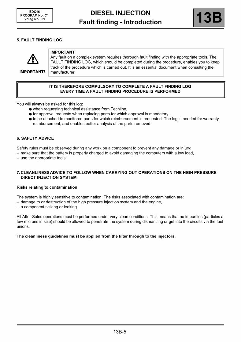
5. FAULT FINDING LOG
You will always be asked for this log: when requesting technical assistance from Techline, for approval requests when replacing parts for which approval is mandatory, to be attached to monitored parts for which reimbursement is requested. The log is needed for warranty
reimbursement, and enables better analysis of the parts removed.
6. SAFETY ADVICE
Safety rules must be observed during any work on a component to prevent any damage or injury:– make sure that the battery is properly charged to avoid damaging the computers with a low load,– use the appropriate tools.
7. CLEANLINESS ADVICE TO FOLLOW WHEN CARRYING OUT OPERATIONS ON THE HIGH PRESSURE DIRECT INJECTION SYSTEM
Risks relating to contamination
The system is highly sensitive to contamination. The risks associated with contamination are:– damage to or destruction of the high pressure injection system and the engine,– a component seizing or leaking.
All After-Sales operations must be performed under very clean conditions. This means that no impurities (particles a few microns in size) should be allowed to penetrate the system during dismantling or get into the circuits via the fuel unions.
The cleanliness guidelines must be applied from the filter through to the injectors.
IMPORTANT!
IMPORTANTAny fault on a complex system requires thorough fault finding with the appropriate tools. The FAULT FINDING LOG, which should be completed during the procedure, enables you to keep track of the procedure which is carried out. It is an essential document when consulting the manufacturer.
IT IS THEREFORE COMPULSORY TO COMPLETE A FAULT FINDING LOGEVERY TIME A FAULT FINDING PROCEDURE IS PERFORMED
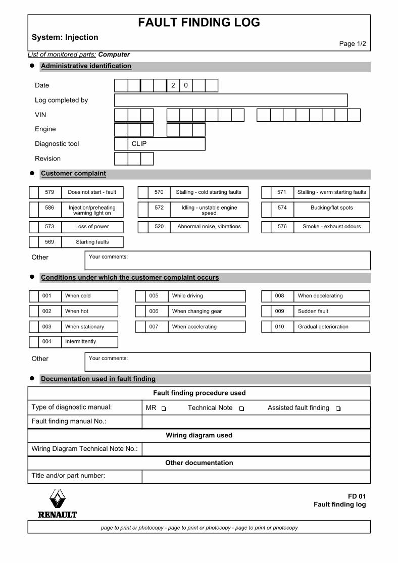
List of monitored parts: Computer
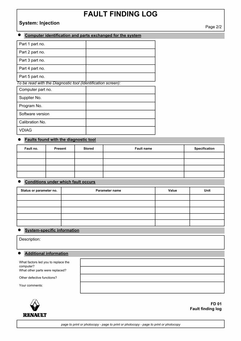
FAULT FINDING LOGSystem: Injection
Page 1/2
Administrative identification
Date 2 0
Log completed by
VIN
Engine
Diagnostic tool CLIP
Revision
Customer complaint
579 Does not start - fault 570 Stalling - cold starting faults 571 Stalling - warm starting faults
586 Injection/preheating warning light on
572 Idling - unstable engine speed
574 Bucking/flat spots
573 Loss of power 520 Abnormal noise, vibrations 576 Smoke - exhaust odours
569 Starting faults
Other Your comments:
Conditions under which the customer complaint occurs
001 When cold 005 While driving 008 When decelerating
002 When hot 006 When changing gear 009 Sudden fault
003 When stationary 007 When accelerating 010 Gradual deterioration
004 Intermittently
Other Your comments:
Documentation used in fault finding
Fault finding procedure used
Type of diagnostic manual: MR Technical Note Assisted fault finding
Fault finding manual No.:
Wiring diagram used
Wiring Diagram Technical Note No.:
Other documentation
Title and/or part number:
FD 01Fault finding log
page to print or photocopy - page to print or photocopy - page to print or photocopy
To be read with the Diagnostic tool (Identification screen):
FAULT FINDING LOGSystem: Injection
Page 2/2
Computer identification and parts exchanged for the system
Part 1 part no.
Part 2 part no.
Part 3 part no.
Part 4 part no.
Part 5 part no.
Computer part no.
Supplier No.
Program No.
Software version
Calibration No.
VDIAG
Faults found with the diagnostic tool
Fault no. Present Stored Fault name Specification
Conditions under which fault occurs
Status or parameter no. Parameter name Value Unit
System-specific information
Description:
Additional information
What factors led you to replace the computer?What other parts were replaced?
Other defective functions?
Your comments:
FD 01Fault finding log
page to print or photocopy - page to print or photocopy - page to print or photocopy
DIESEL INJECTIONFault finding - Cleanliness guidelines 13B
EDC16PROGRAM No: C1
Vdiag No.: 51Fault finding - Cleanliness guidelines
I - RISKS ASSOCIATED WITH CONTAMINATION
The high pressure direct injection system is highly sensitive to contamination. The risks associated with contamination are:
– damage to or destruction of the high pressure injection system,– components jamming,– a component leaking.
All After-Sales operations must be performed under very clean conditions. This means that no impurities (particles a few microns in size) should have entered the system during dismantling.
The cleanliness principle must be applied from the filter to the injectors.
What are the sources of contamination?
metal or plastic chips,– paint,– fibres:– from cardboard,– from brushes,– from paper,– from clothing,– from cloths,– foreign bodies such as hair,– ambient air,– etc.
II - NOTES TO BE FOLLOWED BEFORE ANY OPERATION
Check that you have plugs for the unions to be opened (set of plugs available from the Parts Department). The plugs are single-use only. After use, they must be discarded (once used they are soiled and cleaning is not sufficient to make them reusable). Unused plugs must be discarded.
IMPORTANTCleaning the engine using a high pressure washer is prohibited because of the risk of damaging connections. In addition, moisture may collect in the connectors and create electrical connection faults.
IMPORTANTBefore any work is carried out on the high pressure injection system, protect:– the accessories and timing belts,– the electrical accessories, (starter, alternator, electric power assisted steering pump),– the flywheel surface, to prevent any diesel from running onto the clutch friction plate.
13B-8
DIESEL INJECTIONFault finding - Cleanliness guidelines 13B
13B-9
EDC16PROGRAM No: C1
Vdiag No.: 51
Check that you have hermetically resealable plastic bags for storing removed parts. Parts stored in this way will be less susceptible to the risk of contamination. The bags are to be used once only, and discarded after use.
Use lint-free cleaning cloths (cloth part number 77 11 211 707). Using normal cloth or paper is prohibited. They are not lint-free and could contaminate the fuel circuit. Each cloth should only be used once.
Use fresh cleaning agent for each operation (used cleaning agent is contaminated). Pour it into an uncontaminated container.
For each operation, use a clean brush in good condition (the brush must not shed its bristles).
Use a brush and cleaning agent to clean the unions to be opened.
Blast compressed air over the cleaned parts (tools, workbench, the parts, unions and injection system zones). Check that no bristles remain.
Wash your hands before and during the operation if necessary.
When wearing leather protective gloves cover them with latex gloves to prevent contamination.
III - INSTRUCTIONS TO BE FOLLOWED DURING THE OPERATION
As soon as the circuit is open, all openings must be plugged to prevent impurities from entering the system. The plugs to be used are available from the Parts Department. The plugs must not be reused under any circumstances.
Seal the pouch shut, even if it has to be opened shortly afterwards. Ambient air carries contamination.
All components removed from the injection system must be stored in a hermetically sealed plastic bag once they have been plugged.
Using a brush, cleaning agent, air gun, sponge or normal cloth is strictly prohibited once the circuit has been opened. These items could allow contamination to enter the system.
A new component replacing an old one must not be removed from its packaging until it is to be fitted to the vehicle.
DIESEL INJECTIONFault finding - System operation 13B
13B-10
EDC16PROGRAM No: C1
Vdiag No.: 51Fault finding - System operation
System outline
The high pressure injection system is designed to deliver a precise quantity of diesel fuel to the engine at a set moment.
It is fitted with a 112-track BOSCH EDC16 C3 type computer.
The system is comprised of:– a priming bulb on the low pressure circuit,– a diesel filter,– a high pressure pump with a built-in low pressure pump (transfer pump),– a high pressure regulator mounted on the pump,– an injector rail,– a diesel fuel pressure sensor built into the rail,– four solenoid injectors,– a coolant temperature sensor,– a cylinder reference sensor,– an engine speed sensor,– a turbocharger pressure sensor,– an accelerator pedal potentiometer,– an EGR solenoid valve,– an atmospheric pressure sensor integrated into the injection computer,– an air flow sensor with an air temperature sensor,– a turbocharging pressure limitation solenoid valve,– a motorised damper valve.
The common rail direct high pressure injection system works sequentially (based on the petrol engine multipoint injection).
This injection system reduces operating noise, reduces the volume of pollutant gases and particles and produces high engine torque at low engine speeds thanks to a pre-injection procedure.
The high pressure pump generates the high pressure and transmits it to the injector rail. The actuator located on the pump controls the quantity of diesel fuel supplied, according to the requirement determined by the computer. The rail supplies each injector through a steel pipe.
DIESEL INJECTIONFault finding - System operation 13B
13B-11
EDC16PROGRAM No: C1
Vdiag No.: 51
a) The computer:
Determines the value of injection pressure necessary for the engine to operate correctly and then controls the pressure regulator.Checks that the pressure value is correct by analysing the value transmitted by the pressure sensor located on the rail.Determines the injection duration necessary for supplying the correct quantity of diesel and the moment when injection is required; controls each injector electrically and individually after determining these values.
The flow injected into the engine is determined by:– the duration of injector control,– the rail pressure (regulated by the computer),– the injector opening and closing speed,– the needle stroke (determined by a constant for the type of injector),– the nominal hydraulic flow of the injector (specific to each injector).
The computer manages:– idling regulation,– exhaust gas flow reinjection to the inlet (EGR),– fuel supply check (advance, flow and rail pressure),– the CMV control via the Protection and Switching Unit (centralised coolant temperature management function),– the air conditioning (cold loop function),– the cruise control/speed limiter function,– pre-post heating control,– fault warning lights via the multiplex network.
The high pressure pump is supplied at low pressure by an integrated low pressure pump (transfer pump).It supplies the rail, the pressure of which is controlled by the fuel flow actuator (MPROP) for charging, and for discharging by the injector valves. This compensates for pressure drops. The fuel flow actuator enables the high pressure pump to supply the exact quantity of diesel fuel required to maintain the rail pressure. This component minimises the heat generated and improves engine output. In order to discharge the rail using the injector valves, the valves are controlled by brief electrical pulses which are:
– short enough not to open the injector (passing through the feedback circuit from the injectors),– long enough to open the valves and discharge the rail.

DIESEL INJECTIONFault finding - System operation 13B
13B-12
EDC16PROGRAM No: C1
Vdiag No.: 51
b) Multiplex connection between the different vehicle computers.
The electronic system fitted in this vehicle is multiplexed.This enables dialogue between the various vehicle computers. As a result:
– the activation of the fault warning lights on the instrument panel is performed by the multiplex network, with the vehicle speed sensor on the gearbox deactivated,
– vehicle faults are displayed by the multiplex network,– the vehicle speed sensor on the gearbox is not needed.
The vehicle speed signal on the instrument panel is transmitted by the ABS computer via a wire connection, then sent out on the multiplex network by the instrument panel. The vehicle speed signal is used mainly by the injection computer and the airbag computer.
Some vehicles have adopted a sensor for detecting water in the diesel fuel, located in the filter. If there is water in the diesel fuel, the orange "Injection and pre-post heating" warning light will come on.
The system can inject diesel fuel into the engine at a pressure of up to 1600 bar. Before each operation, check that the injector rail is depressurised and that the fuel temperature is not too high.
You must respect the cleanliness guidelines and safety advice specified in this document for any work on the high pressure injection system.Removal of the internal parts of the pump and injectors is prohibited. Only the fuel flow actuator, the diesel fuel temperature sensor and the venturi can be replaced.
For safety reasons, it is strictly prohibited to undo a high pressure pipe union when the engine is running.
It is not possible to remove the pressure sensor from the fuel rail because this may cause circuit contamination faults. If the pressure sensor fails, the pressure sensor, the rail and the five high pressure pipes must be replaced.
It is forbidden to remove any injection pump pulley bearing the number 070 575. If the pump needs to be replaced, replace the pulley.
Supplying + 12 V directly to any component in the system is prohibited.
Ultrasonic decoking and cleaning are prohibited.
Never start the engine unless the battery is connected correctly.
Disconnect the injection computer when carrying out any welding work on the vehicle.
WARNINGThe engine must not operate with:– Diesel fuel containing more than 10 % diester,– petrol, even in tiny quantities.
DIESEL INJECTIONFault finding - System operation 13B
13B-13
EDC16PROGRAM No: C1
Vdiag No.: 51
c) Hosted functions:
Air conditioning management assistance:
In the case of vehicles with climate control, the EDC16 system has the option of deactivating the air conditioning via the UCH, under certain conditions of use:
– when requested by the driver,– when starting the engine,– if the engine overheats (in order to reduce the power the engine has to supply),– when the engine speed is kept at a very high level (to protect the compressor),– during transitory phases (such as demands for high acceleration when overtaking, anti-stall and start-up) These
conditions are only taken into account when they do not occur repeatedly, to prevent instability in the system (erratic deactivations),
– when certain faults appear.
Cold loop air conditioning management:
The air conditioning is the cold loop type and its management shared between several computers.The injection computer is responsible for:
– authorising cold requests according to the refrigerant pressure, the engine coolant temperature and the engine speed,
– calculating the power absorbed by the compressor (from the refrigerant pressure),– requesting operation of the GMV, from the UPC, according to the vehicle speed, the refrigerant pressure and the
engine coolant temperature.
The driver requests the air conditioning to be switched on by means of the ventilation selector coupled to a switch. The cold air request is authorised or denied depending on the pressure measured. If this pressure is outside the operating limits, the cold loop program is not activated.
Management of the damper valve:
The damper valve currently has three functions:– the valve closes in order to block the passage of air towards the cylinders to shut off the engine. The aim of this is
to stop the engine as quickly as possible and to reduce instabilities as the engine is switched off.– "valving" function depending on the engine operation: the damper valve closes by a few % to create a ''venturi''
effect at the EGR valve passage section.The aim of this is to accelerate the air flow of EGR gases and to reduce the emission of pollutants.
DIESEL INJECTIONFault finding - System operation 13B
13B-14
EDC16PROGRAM No: C1
Vdiag No.: 51
Passenger Compartment Heating Resistor Management:
In order to reduce the time required to heat up the passenger compartment, the vehicle is fitted with Passenger Compartment Heating resistors (RCH). These passenger compartment heating resistors are run and controlled by the UCH. The injection computer authorises or prohibits the operation of the passenger compartment heating resistors according to the operating phases and engine power needs.
Cruise control/speed limiter management:
The vehicle cruise control function, when activated, allows you to keep the vehicle speed at a selected value regardless of the driving conditions encountered.
Using the control buttons, the driver can increase or reduce the speed of the vehicle.
If the driver wishes to exceed the cruising speed, he may:– depress the accelerator pedal and exceed the cruising speed (the vehicle will return to the initial cruising speed
once the driver takes his foot off the pedal),– press the system control buttons.
The cruise control function can be deselected either by:– the system control buttons,– deactivating the cruise control switch,– when system events are detected, such as the brake pedal or clutch being depressed,– when system errors are detected such as an inconsistent vehicle speed.
The cruise function can also be temporarily disabled when the driver wants to increase speed by depressing the accelerator pedal. The cruising speed is resumed when the driver releases the accelerator pedal.The vehicle will then attempt to reach the cruising speed at a controlled acceleration rate.
It is possible to reactivate the vehicle speed control and resume the last cruising speed after deactivation (computer supply not cut off).
When activated (using the selection switch) the vehicle speed limiter function limits the vehicle speed to a preselected value. The driver controls the vehicle in the normal way using the accelerator pedal until the limit speed is reached.
If an attempt is made to exceed this speed, the system ignores the pedal request and controls the vehicle speed in the same way as the cruise control function, provided that the driver keeps the accelerator pedal sufficiently depressed.Like the cruise control function, the limit speed can be modified by pressing or pressing and holding the control buttons.
For safety reasons, it is possible to exceed the limit speed by depressing the accelerator pedal and exceeding the pedal position limit value. The vehicle speed is then totally controlled as a function of pedal position until the speed falls back below the limit speed when the speed limiter function will once again be reactivated.
If the driver wishes to exceed the cruising speed, he may:– exceed the accelerator pedal's kickdown point,– increase the limit speed by pressing or pressing and holding the limit speed switch.
The speed limiter function can be deselected either:– the system control buttons,– by switching off the speed limiter switch,– when system events are detected, such as the brake pedal or clutch being depressed,– when system errors are detected such as an inconsistent vehicle speed.

DIESEL INJECTIONFault finding - System operation 13B
13B-15
EDC16PROGRAM No: C1
Vdiag No.: 51
Exhaust gas recirculation management
The exhaust gas recirculation system comprises a direct current EGR valve controlled by an H bridge in the computer. This system has a built-in valve position feedback potentiometer.The EGR valve is controlled in a closed loop on the change in the air flow measured by the flow sensor.The potentiometer is used in the fault finding procedure for the EGR valve position.
Warning light management:
Instrument panel display
The computer manages the data display on the instrument panel relating to engine operation. This involves six functions:
– the pre-postheating warning light,– the coolant temperature warning light or warning message;– the fault level 1 warning light (non-critical fault),– the fault level 2 warning light (emergency stop),– the OBD warning light (European On Board Diagnostic).
These five functions are represented by 4 or 5 warning lights and/or messages sent by the trip computer.
A 3 second visual inspection is carried out by the injection computer when ignition is switched on (automatic procedure for test managed by the instrument panel).
Orange Pre-post heating/non-critical fault SERVICE warning light (level 1)This light is used both as an in-operation indicator light and as a system fault indicator:
– Continuously lit with + after ignition feed:Indicates preheating of the spark plugs.
– Continuous lighting accompanied by the message CHECK INJECTION or ELECTRONIC FAULT:Indicates a level 1 fault (implies operation in injection system defect mode).The driver should carry out repairs as soon as possible.
Temperature warning light/red EMERGENCY STOP (level 2)This indicator light is used both as an in-operation indicator light and as a system fault warning light. Lights up for 3 seconds when the ignition is switched on (automatic test procedure managed by the instrument panel):
– Continuously lit or alternately lit with ENGINE OVERHEATING message:Indicates engine overheating (the driver is free to choose whether or not to stop the vehicle).
– Continuously lit with the FAULTY INJECTION message:Indicates a level 2 fault (In this case, the injection is automatically cut after a few seconds).The driver should carry out repairs as soon as possible.
ORANGE OBD excess pollution warning lightAn engine symbol accompanied by the message CHECK EMISSION CONTROL.This warning light comes on if the system has one or more OBD faults.This warning light is used to warn the driver of injection faults leading to excessive pollution or that the EOBD* system has been deactivated.The injection computer requests activation of the OBD warning light for a present fault only after three successive driving cycles.A 3 second visual inspection is carried out by the injection computer when ignition is switched on (automatic procedure for test managed by the instrument panel).
*EOBD: Electronic on board diagnostics.
DIESEL INJECTIONFault finding - System operation 13B
13B-16
EDC16PROGRAM No: C1
Vdiag No.: 51
EOBD* management:
The OBD (On Board Diagnostic) system enables the detection of any faults relating to the vehicle emission control system (OBD EURO IV emission control standards exceeded).This system should be active for the entire life of the vehicle.
1. Conditions causing an OBD fault
An OBD fault will be detected after 3 driving cycles and the following parameters will be registered in the computer:– engine load,– vehicle speed– air temperature– coolant temperature,– turbocharging pressure,– rail pressure,– air flow,– distance travelled in miles by the vehicle since activation of the OBD warning light.
It allows the driver to know whether the vehicle has a fault directly linked to the emission control system.
2. System faults indicated by the OBD
Only a few faults are indicated by the OBD system:– DF001 Coolant temperature sensor circuit.– DF003 Atmospheric pressure sensor circuit.– DF011 Sensor feed voltage no. 1.– DF012 Sensor feed voltage no. 2.– DF013 Sensor feed voltage no. 3.– DF038 Computer in 6.DEF EEPROM fault.– DF040 Cylinder 1 injector circuit in CO Open circuit.– DF041 Cylinder 2 injector circuit in CO Open circuit.– DF042 Cylinder 3 injector circuit in CO Open circuit.– DF043 Cylinder 4 injector circuit in CO Open circuit.– DF054 Turbocharging solenoid valve control circuit in CC.0 Short circuit to earth.– DF056 Air flow sensor circuit.– DF209 EGR valve position sensor circuit.– DF621 EGR valve jammed open.
Some repair operations require programming to ensure that certain engine components function correctly.Follow the programming procedures (see Replacement of components), if replacing the exhaust gas recirculation valve or an injector.
*EOBD: Electronic on board diagnostics

DIESEL INJECTIONFault finding - System operation 13B
13B-17
EDC16PROGRAM No: C1
Vdiag No.: 51
3. Conditions for clearing an OBD fault
An OBD fault is cleared in several steps.The fault present in the diagnostic tool is not stored (following repair) until after 3 trips with the vehicle.The OBD warning light will only light up after these 3 driving cycles.The warning light coming on does not always mean that there is a fault on the system.In order that the OBD fault and the display parameters are cleared from the computer, the system needs to go through 40 engine heating cycles.An engine heating cycle is a driving cycle during which:
– the engine coolant temperature reaches at least 71.1 °°°°C,– the engine coolant temperature varies by 22.2 °°°°C in relation to the engine starting temperature.
If one of these conditions is not fulfilled, the OBD fault will still be present or stored in the injection computer.

DIESEL INJECTIONFault finding - Allocation of computer tracks 13B
13B-18
EDC16PROGRAM No: C1
Vdiag No.: 51Fault finding - Allocation of computer tracks
1 - black connector A, 32 tracks 1 - black connector A, 32 tracks (continued)
Track Description
A1 Not used
A2 Cruise control on/off switch
A3 Passenger compartment L1 multiplex line network signal
A4 Passenger compartment H1 multiplex line network signal
B1 Air conditioning inhibition control
B2 Engine speed signal
B3 Not used
B4 K line diagnostic socket output
C1 Not used
C2 Not used
C3 Speed limiter on/off switch
C4 Clutch contact input
D1 Protection and Switching Unit supply (+ after ignition feed)
D2 Cruise control programming control
D3 Cruise control programming feedback signal
D4 Fuel flow signal
E1 Not used
E2 Air conditioning cycle control
E3 Not used
E4 Normally-closed brake switch input
F1 Not used
F2 Accelerator potentiometer load 2 supply
F3 Accelerator potentiometer load 2 signal
F4 Accelerator potentiometer load 2 earth
Track Description
G1 Protection and Switching Unit supply (+ BAT 1 after relay)
G2 Accelerator potentiometer load 1 supply
G3 Not used
G4 Battery earth
H1 Battery earth
H2 Accelerator potentiometer load 1 signal
H3 Accelerator potentiometer load 1 earth
H4 Battery earth
DIESEL INJECTIONFault finding - Allocation of computer tracks 13B
13B-19
EDC16PROGRAM No: C1
Vdiag No.: 51
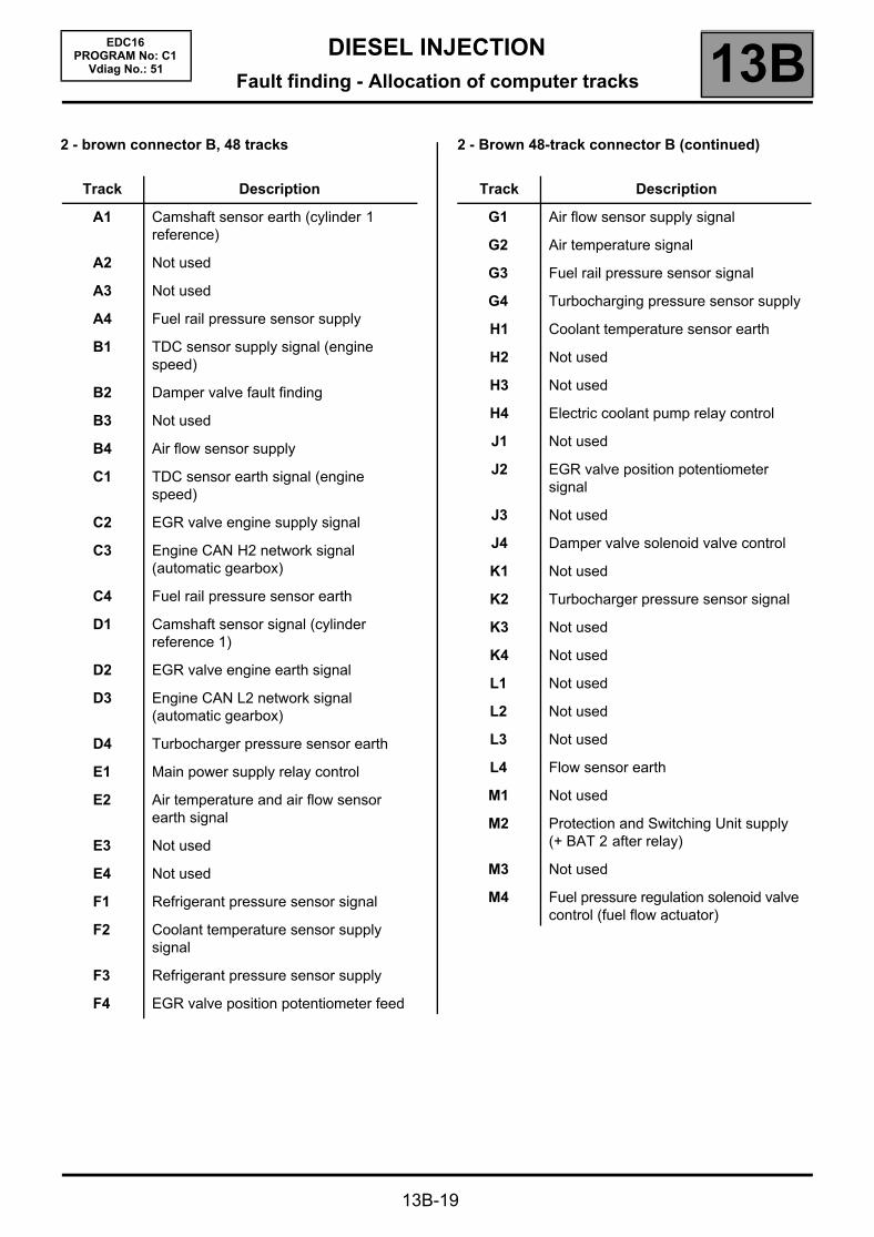
2 - brown connector B, 48 tracks 2 - Brown 48-track connector B (continued)
Track Description
A1 Camshaft sensor earth (cylinder 1 reference)
A2 Not used
A3 Not used
A4 Fuel rail pressure sensor supply
B1 TDC sensor supply signal (engine speed)
B2 Damper valve fault finding
B3 Not used
B4 Air flow sensor supply
C1 TDC sensor earth signal (engine speed)
C2 EGR valve engine supply signal
C3 Engine CAN H2 network signal (automatic gearbox)
C4 Fuel rail pressure sensor earth
D1 Camshaft sensor signal (cylinder reference 1)
D2 EGR valve engine earth signal
D3 Engine CAN L2 network signal (automatic gearbox)
D4 Turbocharger pressure sensor earth
E1 Main power supply relay control
E2 Air temperature and air flow sensor earth signal
E3 Not used
E4 Not used
F1 Refrigerant pressure sensor signal
F2 Coolant temperature sensor supply signal
F3 Refrigerant pressure sensor supply
F4 EGR valve position potentiometer feed
Track Description
G1 Air flow sensor supply signal
G2 Air temperature signal
G3 Fuel rail pressure sensor signal
G4 Turbocharging pressure sensor supply
H1 Coolant temperature sensor earth
H2 Not used
H3 Not used
H4 Electric coolant pump relay control
J1 Not used
J2 EGR valve position potentiometer signal
J3 Not used
J4 Damper valve solenoid valve control
K1 Not used
K2 Turbocharger pressure sensor signal
K3 Not used
K4 Not used
L1 Not used
L2 Not used
L3 Not used
L4 Flow sensor earth
M1 Not used
M2 Protection and Switching Unit supply (+ BAT 2 after relay)
M3 Not used
M4 Fuel pressure regulation solenoid valve control (fuel flow actuator)
DIESEL INJECTIONFault finding - Allocation of computer tracks 13B
13B-20
EDC16PROGRAM No: C1
Vdiag No.: 51
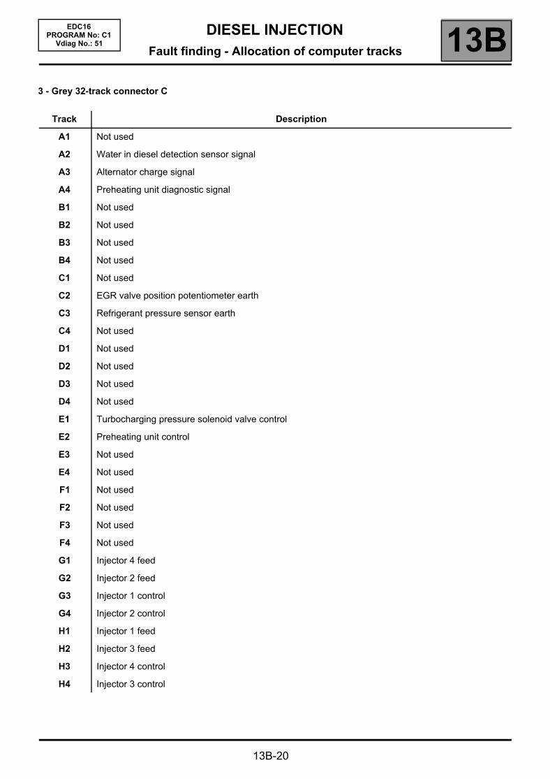
3 - Grey 32-track connector C
Track Description
A1 Not used
A2 Water in diesel detection sensor signal
A3 Alternator charge signal
A4 Preheating unit diagnostic signal
B1 Not used
B2 Not used
B3 Not used
B4 Not used
C1 Not used
C2 EGR valve position potentiometer earth
C3 Refrigerant pressure sensor earth
C4 Not used
D1 Not used
D2 Not used
D3 Not used
D4 Not used
E1 Turbocharging pressure solenoid valve control
E2 Preheating unit control
E3 Not used
E4 Not used
F1 Not used
F2 Not used
F3 Not used
F4 Not used
G1 Injector 4 feed
G2 Injector 2 feed
G3 Injector 1 control
G4 Injector 2 control
H1 Injector 1 feed
H2 Injector 3 feed
H3 Injector 4 control
H4 Injector 3 control
DIESEL INJECTIONFault finding - Replacement of components 13B
13B-21
EDC16PROGRAM No: C1
Vdiag No.: 51Fault finding - Replacement of components
REPLACING OR REPROGRAMMING THE COMPUTER
Two operations must be performed when replacing or reprogramming the computer:SC003 Save computer data and SC001 Enter saved data.
– Use SC003 before the computer is replaced or reprogrammed. This enables certain data to be saved in the diagnostic tool so that the new computer* can be reconfigured like the old one. The saved data are: injector codes, EGR programming, vehicle options.
– Run SC001 after the computer is replaced or reprogrammed. It enables you to rewrite the data (saved by command SC003) to the new computer*.
If you cannot establish dialogue with the computer being replaced: you will not be able to save anything. After replacing the computer, enter the IMA code of each injector manually, reading the code on each injector (see INJECTOR REPLACEMENT).Exhaust gas recirculation valve data is programmed automatically the 1st time the new computer is switched on*.
* new computer or reprogrammed computer.
→ PROCEDURE: Before replacing or reprogramming the computer:
– Select SC003 Save computer data,– if the following message appears: there is a saved file; do you want to overwrite this data?: (this file is the
last save carried out on the tool)– select YES,When the backup is complete, replace the computer or reprogram, then proceed to the next step.
After replacing or reprogramming the computer:– Select SC001 Write saved data, then follow the instructions given by the diagnostic tool,– if the VIN has not been entered (see Computer identification on the main screen),– select VP010 Write VIN,When both these commands have finished:
– switch off the ignition and wait 1 minute before switching the ignition on again.– then check the system faults, and clear any stored faults;– if there are no stored faults, deal with present faults;– clear the faults from the computer memory.Carry out a road test followed by another full check with the diagnostic tool.
End of operation.
IMPORTANT– Switch on the diagnostic tool (mains or cigarette lighter supply).– Connect a battery charger.– Switch off all electrical consumers (lights, interior lights, air conditioning, radio/CD, etc.).– Wait for the engine to cool (engine coolant temperature < 60°, and air temperature < 50°).– The GMV are activated automatically when the computer is being reprogrammed.
IMPORTANT– The injection computer retains the same immobiliser code for life.– The system has no security code.– It is forbidden to perform tests with computers borrowed from the Parts Department or from another vehicle which
must then be returned.– These computers are hard-coded.– If the injection computer appears to be faulty, contact the Techline and refer to the fault finding log.

DIESEL INJECTIONFault finding - Replacement of components 13B
13B-22
EDC16PROGRAM No: C1
Vdiag No.: 51
REPLACING THE INJECTORS
After replacing one or more injectors, re-enter the IMA codes.The system must be configured via the diagnostic socket using the RENAULT CLIP diagnostic tool.
→→→→ PROCEDURE to be followed after one or more injectors are replaced:
IMPORTANTCylinder no. 1 is located at the engine flywheel end.
– make a note of the IMA code(s) engraved on the injector body,– enter these codes in the computer using command SC002 Enter injector codes, then follow the instructions given
by the diagnostic tool,– once the command has finished,– switch off the ignition,– wait 1 min before switching on the ignition again,– return to fault finding mode,– select the Computer identification function from the main screen,– check that the injector codes entered into the computer match those found on the bodies of the injectors:– if the codes do not match, repeat the procedure for command SC002 Enter injector codes;– if the codes do match, check system faults and clear any stored faults;– if there are no stored faults, deal with present faults;– clear the faults from the computer memory.
Carry out a road test followed by another full check with the diagnostic tool.
End of operation.
Note:The IMA coding (individual injector correction) is a calibration made in production on each injector to adjust the flow accurately.These correction values are etched onto the Bakelite body of each injector (6 alphanumeric characters) and then entered into the computer which then controls each injector taking into account their manufacturing variation.
IMPORTANTEngines can only operate correctly if the correct IMA codes have been entered.If no code has been entered or if an invalid code has been entered, the fault DF276 Injector code programming, is present and the engine will be in defect mode (speed heavily limited).If another injector's code has been entered, the system will accept it but will make the wrong correction. This could lead to engine damage, loss of performance and excessive pollution.Always use the correct injector codes for the engine cylinder/computer.

DIESEL INJECTIONFault finding - Replacement of components 13B
13B-23
EDC16PROGRAM No: C1
Vdiag No.: 51
REPLACING THE EXHAUST GAS RECIRCULATION VALVE (EGR valve)
After the exhaust gas recirculation valve has been replaced, the computer must store the new valve's offset and the offset measured the last time the ignition was switched off, which is when the valve closed.Using this data, the computer can detect whether the valve is clogged or seized.
When the valve is replaced, clear the stored offsets so that the program uses the new valve's offset value.
The data linked to this program is compiled in the Emission control/OBD sub-function.– PR128: FIRST EGR VALVE OFFSET.– PR129: LAST EGR VALVE OFFSET > or = PR128 if the valve is new.
Programming PR128 and PR129 must be cleared every time the exhaust gas recirculation valve is replaced.
→→→→ PROCEDURE to be followed after replacing the exhaust gas recirculation valve:– run command SC036 Reset programming;– select EGR valve as the operation type then follow the instructions given by the diagnostic tool,
– when the command is finished;– switch off the ignition,– wait 1 minute before switching on the ignition again;
When the ignition is next switched on again the new EGR valve offset is automatically reprogrammed.
– start the vehicle to enable the last EGR valve offset to be programmed,– switch off the ignition,– wait 1 minute before switching on the ignition again;
The last EGR valve offset reprogrammed is stored on the computer.
– then check the system faults, and clear any stored faults;– if there are no stored faults, deal with present faults;– clear the faults from the computer memory.
Carry out a road test followed by another full check with the diagnostic tool.
End of operation.
Note:When the reinitialisation is completed, the Emission control/OBD sub-function displays:
PR128 = PR129 > 100 %
Note:When the new EGR valve offset is reprogrammed, the Emission control/OBD sub-function displays:
10 % < PR128 < 40 %PR129 > 100 %
Note:When the last new EGR valve offset is reprogrammed, the Emission control/OBD sub-function displays:
10 % < PR128 < 40 %10 % < PR129 < 40 %

DIESEL INJECTIONFault finding - Replacement of components 13B
13B-24
EDC16PROGRAM No: C1
Vdiag No.: 51
REPLACING THE DAMPER VALVE
After replacing the damper valve, reconfigure the computer.The system must be configured via the diagnostic socket using the RENAULT CLIP tool.
→→→→ PROCEDURE to be followed after the damper valve is replaced:
– switch on the ignition,– establish dialogue with the injection computer,– run command SC036 Reset programming;– select Damper valve as the operation type then follow the instructions given by the diagnostic tool,– switch off the ignition,– wait 1 min before switching on the ignition again,– check that PR420 Damper valve error counter = 0;– then check the system faults, and clear any stored faults;– if there are no stored faults, deal with present faults;– clear the faults from the computer memory.
Carry out a road test followed by another full check with the diagnostic tool.
End of operation.
DIESEL INJECTIONFault finding - Replacement of components 13B
13B-25
EDC16PROGRAM No: C1
Vdiag No.: 51
Summary of available configuration readings
NOTES
Configuration readings are used to check the status of configurations performed.The configuration readings cannot be changed.The computer is configured as soon as the one of the vehicle's optional system components is operated.In the event of a fault, consult the interpretation of command RZ005 PROGRAMMING.
LC009: Air conditioning
WITH OR WITHOUT
LC065: Water in diesel fuel sensor
WITH OR WITHOUT
LC120: Cruise control
WITH OR WITHOUT
LC121: Speed limiter
WITH OR WITHOUT
DIESEL INJECTIONFault finding - Fault summary table 13B
13B-26
EDC16PROGRAM No: C1
Vdiag No.: 51Fault finding - Fault summary table
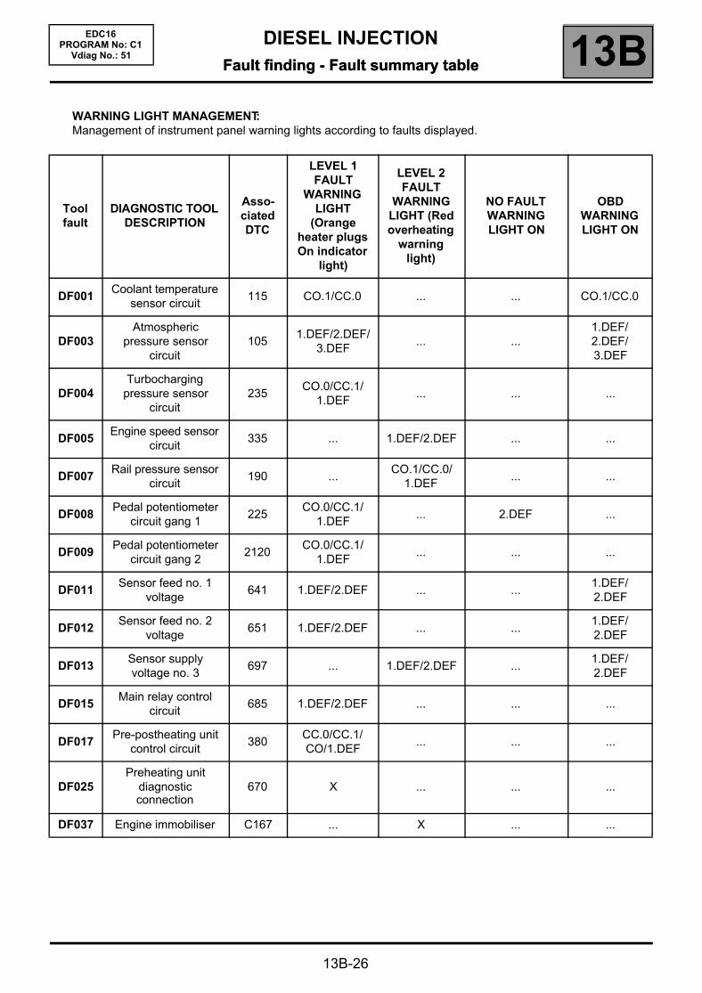
WARNING LIGHT MANAGEMENT:Management of instrument panel warning lights according to faults displayed.
Tool fault
DIAGNOSTIC TOOL DESCRIPTION
Asso-ciated DTC
LEVEL 1 FAULT
WARNING LIGHT
(Orange heater plugs On indicator
light)
LEVEL 2 FAULT
WARNING LIGHT (Red overheating
warning light)
NO FAULT WARNING LIGHT ON
OBD WARNING LIGHT ON
DF001Coolant temperature
sensor circuit115 CO.1/CC.0 ... ... CO.1/CC.0
DF003Atmospheric
pressure sensor circuit
1051.DEF/2.DEF/
3.DEF... ...
1.DEF/2.DEF/3.DEF
DF004Turbocharging
pressure sensor circuit
235CO.0/CC.1/
1.DEF... ... ...
DF005Engine speed sensor
circuit335 ... 1.DEF/2.DEF ... ...
DF007Rail pressure sensor
circuit190 ...
CO.1/CC.0/1.DEF
... ...
DF008Pedal potentiometer
circuit gang 1225
CO.0/CC.1/ 1.DEF
... 2.DEF ...
DF009Pedal potentiometer
circuit gang 22120
CO.0/CC.1/ 1.DEF
... ... ...
DF011Sensor feed no. 1
voltage641 1.DEF/2.DEF ... ...
1.DEF/ 2.DEF
DF012Sensor feed no. 2
voltage651 1.DEF/2.DEF ... ...
1.DEF/ 2.DEF
DF013Sensor supply voltage no. 3
697 ... 1.DEF/2.DEF ...1.DEF/2.DEF
DF015Main relay control
circuit685 1.DEF/2.DEF ... ... ...
DF017Pre-postheating unit
control circuit380
CC.0/CC.1/CO/1.DEF
... ... ...
DF025Preheating unit
diagnostic connection
670 X ... ... ...
DF037 Engine immobiliser C167 ... X ... ...

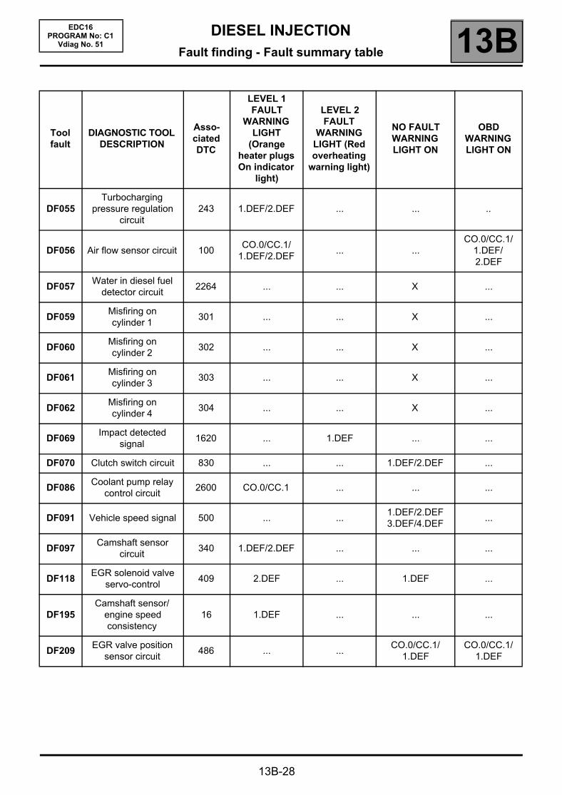
DIESEL INJECTIONFault finding - Fault summary table 13B
13B-27
EDC16PROGRAM No: C1
Vdiag No.: 51
Tool fault
DIAGNOSTIC TOOL DESCRIPTION
Asso-ciated DTC
LEVEL 1 FAULT
WARNING LIGHT
(Orange heater plugs On indicator
light)
LEVEL 2 FAULT
WARNING LIGHT (Red overheating
warning light)
NO FAULT WARNING LIGHT ON
OBD WARNING LIGHT ON
DF038 Computer 6066.DEF/8.DEF/
12.DEF
1.DEF/2.DEF/3.DEF/4.DEF/5.DEF/7.DEF/
10.DEF/11.DEF/ 13.DEF/14.DEF
... 6.DEF
DF039Inlet air temperature
sensor circuit110 ... CC.0/CO.1 ... ...
DF040Cylinder 1 injector
circuit201 CO
CC.1/CC/1.DEF
... CO
DF041Cylinder 2 injector
circuit202 CO
CC.1/CC/1.DEF
... CO
DF042Cylinder 3 injector
circuit203 CO
CC.1/CC/1.DEF
... CO
DF043Cylinder 4 injector
circuit204 CO
CC.1/CC/1.DEF
... CO
DF046 Battery voltage 560 ... ... 1.DEF/2.DEF ...
DF047Computer feed
voltage615 ... ... 1.DEF ...
DF049Refrigerant sensor
circuit530 ... ... CC.1/CO.0 ...
DF050 Brake switch circuit 571 ... ... 1.DEF/2.DEF ...
DF051Cruise control/speed
limiter function575 ... ...
1.DEF/2.DEF/ 3.DEF
...
DF053Rail pressure
regulation function89 3.DEF
CC.0/CC.1/CO/1.DEF/
2.DEF/4.DEF/5.DEF/6.DEF/
7.DEF
... ..
DF054Turbocharging solenoid valve control circuit
33
CO/CC.0/CC.1/1.DEF/
2.DEF/3.DEF/4.DEF/5.DEF
... ... CC.0
DIESEL INJECTIONFault finding - Fault summary table 13B
13B-28
EDC16PROGRAM No: C1
Vdiag No. 51
Tool fault
DIAGNOSTIC TOOL DESCRIPTION
Asso-ciated DTC
LEVEL 1 FAULT
WARNING LIGHT
(Orange heater plugs On indicator
light)
LEVEL 2 FAULT
WARNING LIGHT (Red overheating
warning light)
NO FAULT WARNING LIGHT ON
OBD WARNING LIGHT ON
DF055Turbocharging
pressure regulation circuit
243 1.DEF/2.DEF ... ... ..
DF056 Air flow sensor circuit 100CO.0/CC.1/
1.DEF/2.DEF... ...
CO.0/CC.1/1.DEF/2.DEF
DF057Water in diesel fuel
detector circuit2264 ... ... X ...
DF059Misfiring on cylinder 1
301 ... ... X ...
DF060Misfiring on cylinder 2
302 ... ... X ...
DF061Misfiring on cylinder 3
303 ... ... X ...
DF062Misfiring on cylinder 4
304 ... ... X ...
DF069Impact detected
signal1620 ... 1.DEF ... ...
DF070 Clutch switch circuit 830 ... ... 1.DEF/2.DEF ...
DF086Coolant pump relay
control circuit2600 CO.0/CC.1 ... ... ...
DF091 Vehicle speed signal 500 ... ...1.DEF/2.DEF 3.DEF/4.DEF
...
DF097Camshaft sensor
circuit340 1.DEF/2.DEF ... ... ...
DF118EGR solenoid valve
servo-control409 2.DEF ... 1.DEF ...
DF195Camshaft sensor/
engine speed consistency
16 1.DEF ... ... ...
DF209EGR valve position
sensor circuit486 ... ...
CO.0/CC.1/1.DEF
CO.0/CC.1/1.DEF

DIESEL INJECTIONFault finding - Fault summary table 13B
13B-29
EDC16PROGRAM No: C1
Vdiag No. 51
Tool fault
DIAGNOSTIC TOOL DESCRIPTION
Asso-ciated DTC
LEVEL 1 FAULT
WARNING LIGHT
(Orange heater plugs On indicator
light)
LEVEL 2 FAULT
WARNING LIGHT (Red overheating
warning light)
NO FAULT WARNING LIGHT ON
OBD WARNING LIGHT ON
DF226 Damper valve circuit 638CO/CC/CC.0/CC.1/1.DEF/2.DEF/3.DEF
... ... ...
DF250 ESP function C122 ... ... 1.DEF/2.DEF ...
DF272EGR valve control
circuit403 1.DEF ... 2.DEF ...
DF276Injector code programming
611 1.DEF/2.DEF ... ... ...
DF485Catalytic converter
fault finding422 ... ... X ...
DF532Alternator charge
signal2502
CC.0/CC.1/1.DEF/2.DEF
... ... ...
DF619EGR valve jammed
open2142 X ... ... ...
DF620 EGR valve fouled 2141 X ... ... ...
DF621EGR valve is jammed
open (OBD fault)2413 ... ... X X

DIESEL INJECTIONFault finding - Interpretation of faults 13B
DF001PRESENT
ORSTORED
COOLANT TEMPERATURE SENSOR CIRCUITCC.0 : Short circuit to earthCO.1 : Open circuit or short circuit to + 12 V
NOTES
Conditions for applying the fault finding procedure to stored faults:The fault is declared present:– when an attempt is made to start the engine,– when the engine is running.
Special notes:If the fault is present:
– the coolant temperature: PR064 Coolant temperature is fixed at 119 °C,– the preheating phase is greater than 10 seconds,– the low speed motor-driven fan assembly (GMV 1) is continuously supplied,– if there is a fault with GMV 1, then start GMV 2 for vehicles with air conditioning.– the level 1 warning light is lit,– the OBD warning light will come on after three consecutive driving cycles (starting
+ 5 seconds + switching off the ignition and waiting 1 minute).Use bornier Elé. 1681 or Elé. 1590 for all operations on the computer connectors.
Check the connections of the coolant temperature sensor 4-track connector.Check the injection computer connections.Repair if necessary.
Measure the resistance of the coolant temperature sensor between tracks 2 and 3 of its black connector.Replace the sensor if its resistance is not approximately:
75780 ± 7000 Ω at - 40 °C12,460 ± 122 Ω at - 10 °C2252 ± 112 Ω at 25 °C811 ± 39 Ω at 50 °C283 ± 8 Ω at 80 °C115 ± 3 Ω at 110 °C87 ± 2 Ω at 120 °C
Check the insulation, continuity and the absence of interference resistance on the following connections:
Injection computer brown 48-track connector Btrack F2
Track 3 coolant temperature sensor
Injection computer brown 48-track connector Btrack H1
Track 2 coolant temperature sensor
Repair if necessary.
If the fault is still present, replace the coolant temperature sensor.
AFTER REPAIRDeal with any faults.Carry out a road test followed by another check with the diagnostic tool.
13B-30
EDC16PROGRAM No: C1
Vdiag No. 51Fault finding - Interpretation of faults
EDC16_V51_DF001
DIESEL INJECTIONFault finding - Interpretation of faults 13B
13B-31
EDC16PROGRAM No: C1
Vdiag No.: 51
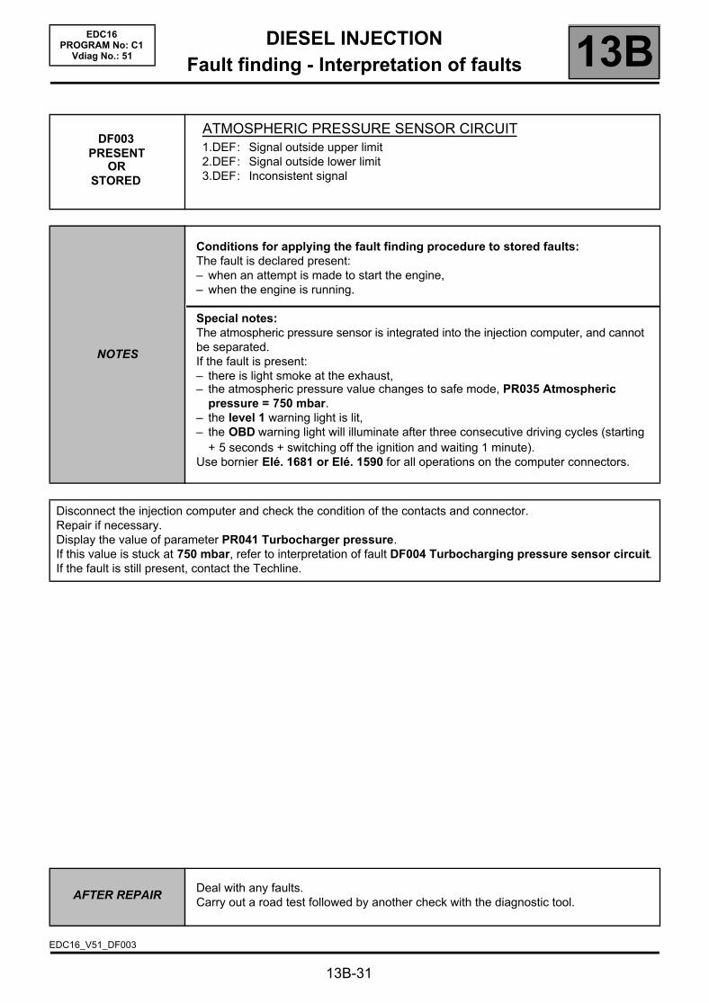
DF003PRESENT
ORSTORED
ATMOSPHERIC PRESSURE SENSOR CIRCUIT1.DEF: Signal outside upper limit2.DEF: Signal outside lower limit3.DEF: Inconsistent signal
NOTES
Conditions for applying the fault finding procedure to stored faults:The fault is declared present:– when an attempt is made to start the engine,– when the engine is running.
Special notes:The atmospheric pressure sensor is integrated into the injection computer, and cannot be separated.If the fault is present:– there is light smoke at the exhaust,– the atmospheric pressure value changes to safe mode, PR035 Atmospheric
pressure = 750 mbar.– the level 1 warning light is lit,– the OBD warning light will illuminate after three consecutive driving cycles (starting
+ 5 seconds + switching off the ignition and waiting 1 minute).Use bornier Elé. 1681 or Elé. 1590 for all operations on the computer connectors.
Disconnect the injection computer and check the condition of the contacts and connector.Repair if necessary.Display the value of parameter PR041 Turbocharger pressure.If this value is stuck at 750 mbar, refer to interpretation of fault DF004 Turbocharging pressure sensor circuit.If the fault is still present, contact the Techline.
AFTER REPAIRDeal with any faults.Carry out a road test followed by another check with the diagnostic tool.
EDC16_V51_DF003
DIESEL INJECTIONFault finding - Interpretation of faults 13B
13B-32
EDC16PROGRAM No: C1
Vdiag No.: 51
DF004PRESENT
ORSTORED
TURBOCHARGING PRESSURE SENSOR CIRCUITCO.0 : Open circuit or short circuit to earthCC.1 : Short circuit to + 12 V1.DEF: Signal incoherence
NOTES
Conditions for applying the fault finding procedure to stored faults:The fault is declared present:– when an attempt is made to start the engine,– when the engine is running.
Special notes:If the fault is present:– the EGR function is inhibited,– the turbocharging pressure sensor is in defect mode, PR041 = 750 mbar,– the level 1 warning light is lit.Use bornier Elé. 1681 or Elé. 1590 for any operation on the injection computer connectors.
Order of priority in the event of more than one fault:Deal with fault DF011 Sensor feed no. 1 voltage first if it is present or stored.
CO.0 NOTES None
Check the turbocharger pressure sensor connections.Check the injection computer connections.Repair if necessary.
Check the continuity and insulation against earth of the following connections:
Injection computer brown 48-track connector B,track G4
Track 3 turbocharging pressure sensor connector
Injection computer brown 48-track connector B,track K2
Track 4 turbocharger pressure sensor connector
Repair if necessary.
If the fault is still present, replace the turbocharger pressure sensor.
AFTER REPAIRDeal with any faults.Carry out a road test followed by another check with the diagnostic tool.
EDC16_V51_DF004

DIESEL INJECTIONFault finding - Interpretation of faults 13B
13B-33
EDC16PROGRAM No: C1
Vdiag No.: 51
DF004CONTINUED 1
CC.1 NOTES None
Check the turbocharger pressure sensor connections.Check the injection computer connections.Repair if necessary.
Check the continuity and insulation against + 12 volts of the following connections:
Injection computer brown 48-track connector B,track G4
Track 3 turbocharging pressure sensor connector
Injection computer brown 48-track connector B,track D4
Track 1 turbocharging pressure sensor connector
Injection computer brown 48-track connector B,track K2
Track 4 turbocharger pressure sensor connector
Repair if necessary.
If the fault is still present, replace the turbocharger pressure sensor.
AFTER REPAIRDeal with any faults.Carry out a road test followed by another check with the diagnostic tool.
DIESEL INJECTIONFault finding - Interpretation of faults 13B
13B-34
EDC16PROGRAM No: C1
Vdiag No.: 51
DF004CONTINUED 2
1.DEF NOTES None
In the event of a combination of faults with DF003 Atmospheric pressure sensor circuit, display parameter PR041 Turbocharging pressure.If this value is locked at 750 mbar and PR035 Atmospheric pressure is displaying a different value, replace the turbocharging pressure sensor.
Check the turbocharger pressure sensor connections.Check the injection computer connections.Repair if necessary.
Check for continuity and the absence of interference resistance of the following connections:
Injection computer brown 48-track connector B,track G4
Track 3 turbocharging pressure sensor connector
Injection computer brown 48-track connector B,track D4
Track 1 turbocharging pressure sensor connector
Injection computer brown 48-track connector B,track K2
Track 4 turbocharger pressure sensor connector
Repair if necessary.
If the fault is still present, contact the Techline.
AFTER REPAIRDeal with any faults.Carry out a road test followed by another check with the diagnostic tool.

DIESEL INJECTIONFault finding - Interpretation of faults 13B
13B-35
EDC16PROGRAM No: C1
Vdiag No.: 51
DF005PRESENT
ORSTORED
ENGINE SPEED SENSOR CIRCUIT1.DEF : No signal2.DEF: Signal incoherence
NOTES
Conditions for applying fault finding procedures to stored faults:The fault is declared present:– when an attempt is made to start the engine,– when the engine is running.
Special notes:Use bornier Elé. 1681 or Elé. 1590 for all operations on the computer connectors.The engine speed sensor is consistent with the camshaft sensor.If the fault is present:
– it is impossible to start the engine or the engine stops,– the level 2 warning light is lit.
Check the engine speed sensor connections.Repair if necessary.Check that the sensor is correctly mounted and that the flywheel target is not damaged.Check that the gap between the engine speed sensor and the flywheel is 0.5 to 1.8 mm.Measure the resistance of the engine speed sensor between terminals A and B of the black connector.If the winding resistance is not 800 ± 80 Ω at an engine temperature of 20 °C, replace the engine speed sensor.
Check the injection computer connections.Repair if necessary.
Check for continuity and the absence of interference resistance of the following connections:
Injection computer brown 48-track connector Btrack B1
Track A engine speed sensor
Injection computer brown 48-track connector Btrack C1
Track B engine speed sensor
Repair if necessary.If the fault is still present, contact the Techline.
AFTER REPAIRDeal with any faults.Carry out a road test followed by another check with the diagnostic tool.
EDC16_V51_DF005
DIESEL INJECTIONFault finding - Interpretation of faults 13B
13B-36
EDC16PROGRAM No: C1
Vdiag No.: 51
DF007 PRESENT
ORSTORED
RAIL PRESSURE SENSOR CIRCUITCC.0 : Short circuit to earthCO.1 : Open circuit or short circuit to + 12 V1.DEF: Offset at minimum threshold
NOTES
Conditions for applying the fault finding procedure to stored faults:The fault is declared present after repeated engine starts or with the engine running.
Special notes:Use bornier Elé. 1681 or Elé. 1590 for all operations on the computer connectors.If the fault is present:
– the engine will stop immediately,– it is impossible to restart,– the level 2 warning light is lit.
Priorities when dealing with a number of faults:Deal with fault DF013 Sensor supply voltage no. 3 first, if it is present or stored.
CC.0 NOTES None
Check the rail pressure sensor connectors.Check the injection computer connections.Repair if necessary.
Check the continuity and insulation to earth of the following connections:
Injection computer brown 48-track connector Btrack G3
Track 2 rail pressure sensor
Brown 48-track connector B injection computertrack A4
Track 3 rail pressure sensor
Repair if necessary.
If the fault is still present, replace the rail pressure sensor and tighten to 35 ± 5 Nm.Follow the recommended safety advice (see cleanliness advice).
AFTER REPAIRDeal with any faults.Carry out a road test followed by another check with the diagnostic tool.
EDC16_V51_DF007

DIESEL INJECTIONFault finding - Interpretation of faults 13B
13B-37
EDC16PROGRAM No: C1
Vdiag No.: 51
DF007CONTINUED 1
CO.1 NOTES None
Check the rail pressure sensor connectors.Check the injection computer connections.Repair if necessary.
Check for continuity and insulation to + 12 V on the following connections:
Injection computer brown 48-track connector Btrack G3
Track 2 rail pressure sensor
Injection computer brown 48-track connector Btrack C4
Track 1 rail pressure sensor
Injection computer brown 48-track connector Btrack A4
Track 3 rail pressure sensor
Repair if necessary.
If the fault is still present, replace the rail pressure sensor and tighten to 35 ± 5 Nm.Observe the safety advice given in the Introduction section.
AFTER REPAIRDeal with any faults.Carry out a road test followed by another check with the diagnostic tool.

DIESEL INJECTIONFault finding - Interpretation of faults 13B
13B-38
EDC16PROGRAM No: C1
Vdiag No.: 51
DF007CONTINUED 2
1.DEF NOTES None
Check the rail pressure sensor connectors.Check the injection computer connections.Repair if necessary.
Check for continuity and absence of interference resistance of the following connections:
Injection computer brown 48-track connector Btrack G3
Track 2 rail pressure sensor
Injection computer brown 48-track connector B,track A4
Track 3 rail pressure sensor
Injection computer brown 48-track connector B,track C4
Track 1 rail pressure sensor
Repair if necessary.
With the ignition on, and engine switched off for over 1 minute:Display the parameter PR038 Rail pressure in the Fuel circuit, Engine control function tab,– If the value is below 50 bar, the sensor is in order.In this case, contact the Techline.– If the pressure is above 50 bar, replace the rail pressure sensor and tighten to 35 ± 5 Nm.Follow the recommended safety advice (see cleanliness advice).
AFTER REPAIRDeal with any faults.Carry out a road test followed by another check with the diagnostic tool.
DIESEL INJECTIONFault finding - Interpretation of faults 13B
13B-39
EDC16PROGRAM No: C1
Vdiag No.: 51
DF008PRESENT
ORSTORED
PEDAL POTENTIOMETER CIRCUIT GANGED CIRCUIT 1CO.0 : Open circuit or short circuit to earthCC.1 : Short circuit to + 12 V1.DEF: Signal incoherence2.DEF: Accelerator pedal sensor locked
NOTES
Conditions for applying the fault finding procedure to stored faults:The fault is declared present after a series of full load/no load actions on the accelerator pedal.
Special notes:Turbocharging, passenger compartment heating resistor activation and the cruise control/speed limiter are not activated.If CO.0, CC.1, 1.DEF is present the level 1 warning light is lit.The engine speed is set at 1,400 rpm if there is a fault on gang 1 and 2 of the pedal potentiometer and the engine torque is limited.Use bornier Elé. 1681 or Elé. 1590 for all operations on the computer connectors.
Priorities when dealing with a number of faults:Deal with fault DF011 Sensor feed no. 1 voltage first if it is present or stored.
WARNINGThis fault may appear if the wiring harness has been damaged.Follow the procedure described in the Wiring Check in the Introduction.This check enables the condition and the conformity of the engine wiring harness to be checked.
CO.0 NOTES
Priorities when dealing with a number of faults:If fault DF009 Pedal potentiometer circuit gang 2 is present at the same time, check that the pedal sensor connector is connected correctly.
Check the pedal potentiometer connections.Check the injection computer connections.Repair if necessary.
AFTER REPAIRDeal with any faults.Carry out a road test followed by another check with the diagnostic tool.
EDC16_V51_DF008

DIESEL INJECTIONFault finding - Interpretation of faults 13B
13B-40
EDC16PROGRAM No: C1
Vdiag No.: 51
DF008CONTINUED 1
Check the continuity and insulation to earth of the following connections:
Injection computer 32-track black connector A,track H2
Track 4 pedal potentiometer connector
Injection computer 32-track black connector Atrack G2
Track 3 pedal potentiometer connector
Repair if necessary.
Measure the resistance on the pedal potentiometer on gang 1 between tracks 5 and 3.Replace the pedal potentiometer if the resistance is not approximately 1.7 ± 0.9 kΩ.
CC.1 NOTES None
Check the pedal potentiometer connections.Check the injection computer connections.Repair if necessary.
Check for continuity and insulation to + 12 V on the following connections:
Injection computer 32-track black connector A,track H2
Track 4 pedal potentiometer connector
Injection computer 32-track black connector Atrack G2
Track 3 pedal potentiometer connector
Injection computer 32-track black connector A,track H3
Track 5 pedal potentiometer connector
Repair if necessary.
Measure the resistance on the pedal potentiometer on gang 1 between tracks 5 and 3.Replace the pedal potentiometer if the resistance is not approximately 1.7 ± 0.9 kΩ.
AFTER REPAIRDeal with any faults.Carry out a road test followed by another check with the diagnostic tool.
DIESEL INJECTIONFault finding - Interpretation of faults 13B
13B-41
EDC16PROGRAM No: C1
Vdiag No.: 51
DF008CONTINUED 2
1.DEF NOTES None
Check the pedal potentiometer connections.Check the injection computer connections.Repair if necessary.
Check for continuity and absence of interference resistance of the following connections:
Injection computer black 32-track connector A,track H2
Track 4 pedal potentiometer sensor
Injection computer black 32-track connector A,track G2
Track 3 pedal potentiometer sensor
Injection computer black 32-track connector A,track H3
Track 5 pedal potentiometer sensor
Injection computer black 32-track connector A,track F3
Track 1 pedal potentiometer sensor
Injection computer black 32-track connector A,track F2
Track 2 pedal potentiometer sensor
Injection computer black 32-track connector A,track F4
Track 6 pedal potentiometer sensor
If the fault is still present, replace the pedal potentiometer.
2.DEF NOTES None
Check the mechanical condition of the accelerator pedal:– locked in full load position,– with the pedal blocked by an external component.Repair if necessary.Vary the position of the pedal and refer to the conformity check in order to check the operating values of the accelerator pedal potentiometer.If the values displayed are inconsistent, replace the accelerator pedal potentiometer.
AFTER REPAIRDeal with any faults.Carry out a road test followed by another check with the diagnostic tool.

DIESEL INJECTIONFault finding - Interpretation of faults 13B
13B-42
EDC16PROGRAM No: C1
Vdiag No.: 51
DF009PRESENT
ORSTORED
PEDAL POTENTIOMETER CIRCUIT GANGED CIRCUIT 2CO.0 : Open circuit or short circuit to earthCC.1 : Short circuit to + 12 V1.DEF: Signal incoherence
NOTES
Conditions for applying the fault finding procedure to stored faults:The fault is declared present after a series of full load/no load actions on the accelerator pedal.
Special notes:Turbocharging, passenger compartment heating resistor activation and the cruise control/speed limiter are not activated.If the fault is present, the level 1 warning light is lit.The engine speed is set at 1,400 rpm if there is a fault on gang 1 and 2 of the pedal potentiometer and the engine torque is limited.Use bornier Elé. 1681 or Elé. 1590 for all operations on the computer connectors.
Priorities when dealing with a number of faults:Deal with fault DF012 Sensor feed no. 2 voltage first, if it is present or stored.
WARNINGThis fault may appear if the wiring harness has been damaged.Follow the procedure described in Wiring check in the Introduction.This check enables the condition and the conformity of the engine wiring harness to be checked.
CO.0 NOTES
Priorities when dealing with a number of faults:If fault DF008 Pedal potentiometer circuit track 1 is present at the same time, check that the sensor is connected correctly.
Check the pedal potentiometer connections.Check the injection computer connections.Repair if necessary.
AFTER REPAIRDeal with any faults.Carry out a road test followed by another check with the diagnostic tool.
EDC16_V51_DF009

DIESEL INJECTIONFault finding - Interpretation of faults 13B
13B-43
EDC16PROGRAM No: C1
Vdiag No.: 51
DF009CONTINUED 1
Check the continuity and insulation to earth of the following connections:
Injection computer 32-track black connector A,track F3
Track 1 pedal potentiometer connector
Injection computer 32-track black connector A,track F2
Track 2 pedal potentiometer connector
Repair if necessary.
Measure the resistance on the pedal potentiometer on gang 2 between tracks 2 and 6.Replace the pedal potentiometer if the resistance is not approximately 2.85 ± 2.05 kΩ.
CC.1 NOTES
Priorities when dealing with a number of faults:If fault DF008 Pedal potentiometer circuit track 1 is present at the same time, check that the sensor is connected correctly.
Check the pedal potentiometer connections.Check the injection computer connections.Repair if necessary.
Check for continuity and insulation to + 12 V on the following connections:
Injection computer 32-track black connector A,track F3
Track 1 pedal potentiometer connector
Injection computer 32-track black connector A,track F2
Track 2 pedal potentiometer connector
Injection computer 32-track black connector A,track F4
Track 6 pedal potentiometer connector
Repair if necessary.
Measure the resistance on the pedal potentiometer on gang 2 between tracks 2 and 6.Replace the pedal potentiometer if its resistance is not approximately: 2.85 kΩ ± 2.05.
AFTER REPAIRDeal with any faults.Carry out a road test followed by another check with the diagnostic tool.
DIESEL INJECTIONFault finding - Interpretation of faults 13B
13B-44
EDC16PROGRAM No: C1
Vdiag No.: 51
DF009CONTINUED 2
1.DEF NOTES None
Check the rail pressure sensor connectors.Check the injection computer connections.Repair if necessary.
Check for continuity and absence of interference resistance of the following connections:
Injection computer black 32-track connector A,track F3
Track 1 pedal potentiometer sensor
Injection computer black 32-track connector A,track F2
Track 2 pedal potentiometer sensor
Injection computer black 32-track connector A,track F4
Track 6 pedal potentiometer sensor
Injection computer black 32-track connector A,track H2
Track 4 pedal potentiometer sensor
Injection computer black 32-track connector A,track G2
Track 3 pedal potentiometer sensor
Injection computer black 32-track connector A,track H3
Track 5 pedal potentiometer sensor
Repair if necessary.
If the fault is still present, replace the pedal potentiometer.
AFTER REPAIRDeal with any faults.Carry out a road test followed by another check with the diagnostic tool.

DIESEL INJECTIONFault finding - Interpretation of faults 13B
13B-45
EDC16PROGRAM No: C1
Vdiag No.: 51
DF011PRESENT
ORSTORED
SENSOR SUPPLY VOLTAGE No. 11.DEF: Sensor reference voltage too low2.DEF: Sensor reference voltage too high
NOTES
Conditions for applying the fault finding procedure to stored faults:The fault is declared present after carrying out a road test or after several attempts at starting the engine.
Special notes:If the fault is present:– the cruise control/speed limiter function is inhibited,– turbocharging is inhibited,– the engine speed is limited,– the level 1 warning light is lit,– the OBD warning light will illuminate after three consecutive driving cycles (starting
+ 5 seconds + switching off the ignition and waiting 1 minute).Use bornier Elé. 1681 or Elé. 1590 for any operation on the injection computer connectors.
WARNINGThis fault may appear if the wiring harness has been damaged.Follow the procedure described in Wiring check in the Introduction.This check enables the condition and the conformity of the engine wiring harness to be checked.
1.DEF2.DEF
NOTES
Priorities when dealing with a number of faults:If fault DF008 Pedal potentiometer circuit track 1 is present at the same time, check that the sensor is connected correctly.In the event of the simultaneous presence of fault DF004 Turbocharging pressure sensor circuit, check that the turbocharger pressure sensor circuit connector is connected correctly.
The sensors connected to feed no. 1 are:– Turbocharger pressure sensor.– Accelerator pedal potentiometer sensor, gang 1.To locate a faulty sensor and/or connection, disconnect one of these sensors then check whether the fault becomes stored.If the fault is still present, start the operation again with the other sensor.(Wait a few seconds after each disconnection so that the computer can carry out the check).If the fault is stored after disconnection, change the faulty sensor or repair the connection.Clear the faults created by the multiple disconnections.
AFTER REPAIRDeal with any faults.Carry out a road test followed by another check with the diagnostic tool.
EDC16_V51_DF011
DIESEL INJECTIONFault finding - Interpretation of faults 13B
13B-46
EDC16PROGRAM No: C1
Vdiag No.: 51
DF011CONTINUED
If the fault is still present when both these sensors have been disconnected:1. Check the insulation against earth of the following connections:
Injection computer brown 48-track connector B,track G4
Track 3 of the turbocharger pressure sensor
Injection computer brown 48-track connector B,track K2
Track 4 of the turbocharger pressure sensor
Injection computer black 32-track connector A,track G2
Track 3 of the accelerator pedal potentiometer gang 1
Injection computer black 32-track connector A,track H2
Track 4 of the accelerator pedal potentiometer track 1
Repair if necessary.
2. Check the insulation against + 12 V for following connections:
Injection computer brown 48-track connector B,track K2
Track 4 of the turbocharger pressure sensor
Injection computer brown 48-track connector B,track D4
Track 1 of the turbocharger pressure sensor
Injection computer brown 48-track connector B,track G4
Track 3 of the turbocharger pressure sensor
Injection computer black 32-track connector A,track H3
Track 5 of the accelerator pedal potentiometer gang 1
Injection computer black 32-track connector B,track H2
Track 4 of the accelerator pedal potentiometer gang 1
Injection computer black 32-track connector B,track G2
Track 3 of the accelerator pedal potentiometer gang 1
Repair if necessary.
3. Check the insulation between the following connections after disconnecting the sensors and injection computer:
– tracks 1 and 3 of the turbocharging pressure sensor connector,– tracks 3 and 5 of the pedal gang 1 sensor connector.If these checks do not produce the correct results, replace the faulty sensor(s).If the fault is still present, contact the Techline.
AFTER REPAIRDeal with any faults.Carry out a road test followed by another check with the diagnostic tool.

DIESEL INJECTIONFault finding - Interpretation of faults 13B
13B-47
EDC16PROGRAM No: C1
Vdiag No.: 51
DF012PRESENT
ORSTORED
SENSOR SUPPLY VOLTAGE No. 21.DEF: Sensor reference voltage too low2.DEF: Sensor reference voltage too high
NOTES
Conditions for applying the fault finding procedure to stored faults:The fault is declared present following a road test or after attempting to start the engine several times.
Special notes:If the fault is present:– the EGR functions and passenger compartment heating resistance functions are
inhibited,– the cruise control/speed limiter function is inhibited,– the engine speed is limited,– the level 1 warning light is lit,– the OBD warning light will illuminate after three consecutive driving cycles (starting
+ 5 seconds + switching off the ignition and waiting 1 minute).Use bornier Elé. 1681 or Elé. 1590 for any operation on the injection computer connectors.
WARNINGThis fault may appear if the wiring harness has been damaged.Follow the procedure described in Wiring check in the Introduction.This check enables the condition and the conformity of the engine wiring harness to be checked.
The sensors connected to feed no. 2 are:– EGR valve position sensor.– Sensor for accelerator pedal potentiometer track 2To locate a faulty sensor and/or connection, disconnect one of these sensors then check whether the fault becomes stored.If the fault is still present, repeat the operation with the other sensors.(Wait a few seconds after each disconnection so that the computer can carry out the check).If the fault is stored after disconnection, change the faulty sensor or repair the connection.Clear the faults created by the multiple disconnections.
AFTER REPAIRDeal with any faults.Carry out a road test followed by another check with the diagnostic tool.
EDC16_V51_DF012
DIESEL INJECTIONFault finding - Interpretation of faults 13B
13B-48
EDC16PROGRAM No: C1
Vdiag No.: 51
DF012CONTINUED
If the fault is still present when both these sensors have been disconnected:1. Check the insulation against earth of the following connections:
Injection computer brown 48-track connector B,track F4
Track 2 of the EGR valve connector
Injection computer brown 48-track connector B,track J2
Track 6 of the EGR valve connector
Injection computer black 32-track connector A,track F2
Track 2 of the accelerator pedal potentiometer gang 2
Injection computer black 32-track connector A,track F3
Track 1 of the accelerator pedal potentiometer gang 2
Repair if necessary.
2. Check the insulation against + 12 V for following connections:
Injection computer brown connector B track F4 Track 2 of the EGR valve connector
Injection computer brown connector B track J2 Track 6 of the EGR valve connector
Injection computer grey connector C track C2 Track 4 of the EGR valve connector
Injection computer black connector A, track F2 Track 2 of the accelerator pedal potentiometer gang 2
Injection computer black connector A, track F3 Track 1 of the accelerator pedal potentiometer gang 2
Injection computer black connector A, track F4 Track 6 of the accelerator pedal potentiometer gang 2
Repair if necessary.
3. Check the insulation between the following connections after disconnecting the sensors and injection computer:
– tracks 2 and 6 of the pedal track 2 sensor connector.– tracks 2 and 4 of the EGR valve position sensor connector.If these checks do not produce the correct results, replace the faulty sensor(s).If the fault is still present, contact the Techline.
AFTER REPAIRDeal with any faults.Carry out a road test followed by another check with the diagnostic tool.
DIESEL INJECTIONFault finding - Interpretation of faults 13B
13B-49
EDC16PROGRAM No: C1
Vdiag No.: 51
DF013 PRESENT
ORSTORED
SENSOR SUPPLY VOLTAGE No. 31.DEF: Sensor reference voltage too low2.DEF: Sensor reference voltage too high
NOTES
Conditions for applying the fault finding procedure to stored faults:The fault is declared present following a road test or after attempting to start the engine several times.
Special notes:If the fault is present:– the EGR function is inhibited,– the engine stops,– the level 2 warning light is lit,– the OBD warning light will illuminate after three consecutive driving cycles (starting
+ 5 seconds + switching off the ignition and waiting 1 minute).Use bornier Elé. 1681 or Elé. 1590 for any operation on the injection computer connectors.
WARNINGThis fault may appear if the wiring harness has been damaged.Follow the procedure described in Wiring check in the Introduction.This check enables the condition and the conformity of the engine wiring harness to be checked.
The sensors connected to supply no. 3 are:– Rail pressure sensor.– Air flow sensor.To locate a faulty sensor and/or connection, disconnect one of these sensors then check whether the fault becomes stored.If the fault is still present, repeat the operation with the other sensors.(Wait a few seconds after each disconnection so that the computer can carry out the check).If the fault is stored after disconnection, change the faulty sensor or repair the connection.Clear the faults created by the multiple disconnections.
AFTER REPAIRDeal with any faults.Carry out a road test followed by another check with the diagnostic tool.
EDC16_V51_DF013
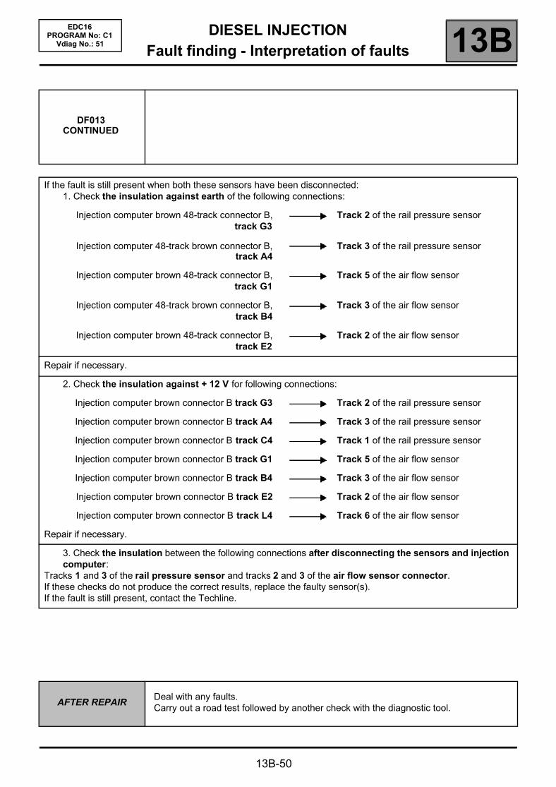
DIESEL INJECTIONFault finding - Interpretation of faults 13B
13B-50
EDC16PROGRAM No: C1
Vdiag No.: 51
DF013CONTINUED
If the fault is still present when both these sensors have been disconnected:1. Check the insulation against earth of the following connections:
Injection computer brown 48-track connector B,track G3
Track 2 of the rail pressure sensor
Injection computer 48-track brown connector B,track A4
Track 3 of the rail pressure sensor
Injection computer brown 48-track connector B,track G1
Track 5 of the air flow sensor
Injection computer 48-track brown connector B,track B4
Track 3 of the air flow sensor
Injection computer brown 48-track connector B,track E2
Track 2 of the air flow sensor
Repair if necessary.
2. Check the insulation against + 12 V for following connections:
Injection computer brown connector B track G3 Track 2 of the rail pressure sensor
Injection computer brown connector B track A4 Track 3 of the rail pressure sensor
Injection computer brown connector B track C4 Track 1 of the rail pressure sensor
Injection computer brown connector B track G1 Track 5 of the air flow sensor
Injection computer brown connector B track B4 Track 3 of the air flow sensor
Injection computer brown connector B track E2 Track 2 of the air flow sensor
Injection computer brown connector B track L4 Track 6 of the air flow sensor
Repair if necessary.
3. Check the insulation between the following connections after disconnecting the sensors and injection computer:
Tracks 1 and 3 of the rail pressure sensor and tracks 2 and 3 of the air flow sensor connector.If these checks do not produce the correct results, replace the faulty sensor(s).If the fault is still present, contact the Techline.
AFTER REPAIRDeal with any faults.Carry out a road test followed by another check with the diagnostic tool.
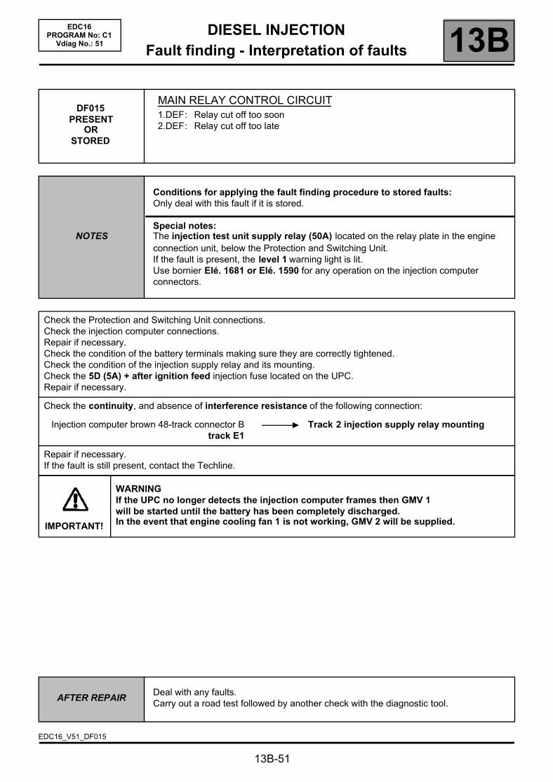
DIESEL INJECTIONFault finding - Interpretation of faults 13B
13B-51
EDC16PROGRAM No: C1
Vdiag No.: 51
DF015PRESENT
ORSTORED
MAIN RELAY CONTROL CIRCUIT1.DEF: Relay cut off too soon2.DEF: Relay cut off too late
NOTES
Conditions for applying the fault finding procedure to stored faults:Only deal with this fault if it is stored.
Special notes:The injection test unit supply relay (50A) located on the relay plate in the engine connection unit, below the Protection and Switching Unit.If the fault is present, the level 1 warning light is lit.Use bornier Elé. 1681 or Elé. 1590 for any operation on the injection computer connectors.
Check the Protection and Switching Unit connections.Check the injection computer connections.Repair if necessary.Check the condition of the battery terminals making sure they are correctly tightened.Check the condition of the injection supply relay and its mounting.Check the 5D (5A) + after ignition feed injection fuse located on the UPC.Repair if necessary.
Check the continuity, and absence of interference resistance of the following connection:
Injection computer brown 48-track connector Btrack E1
Track 2 injection supply relay mounting
Repair if necessary.If the fault is still present, contact the Techline.
IMPORTANT!
WARNINGIf the UPC no longer detects the injection computer frames then GMV 1will be started until the battery has been completely discharged.In the event that engine cooling fan 1 is not working, GMV 2 will be supplied.
AFTER REPAIRDeal with any faults.Carry out a road test followed by another check with the diagnostic tool.
EDC16_V51_DF015

DIESEL INJECTIONFault finding - Interpretation of faults 13B
13B-52
EDC16PROGRAM No: C1
Vdiag No.: 51
DF017PRESENT
ORSTORED
PREHEATING UNIT CONTROL CIRCUITCC.1 : Short circuit to + 12 VCC.0 : Open circuit or short circuit to earthCO : Open circuit1.DEF: Internal electronic fault
NOTES
Conditions for applying fault finding procedures to stored faults:The fault is declared present after attempting to start the engine several times or after an actuator command AC001 Preheating unit.
Special notes:If the fault is present, it is difficult or even impossible to start the vehicle when cold.If the fault is present, the level 1 warning light is lit.Use bornier Elé. 1681 or Elé. 1590 for any operation on the injection computer connectors.
CC.1 NOTES None
Check the preheating unit connections and the heating plug supply cables.Check the injection computer connections.Repair if necessary.
Check the condition of the F2 (70A) supply fuse on the power supply fuse board.Check the continuity and insulation against + 12 V of the following connections:
Injection computer grey 32-track connector C,track E2
Track 8 preheating unit
Injection computer grey 32-track connector C,track A4
Track 3 preheating unit
Repair if necessary.If the fault is still present, replace the preheating unit.
AFTER REPAIRDeal with any faults.Carry out a road test followed by another check with the diagnostic tool.
EDC16_V51_DF017
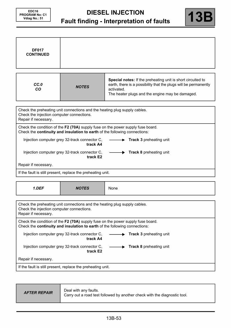
DIESEL INJECTIONFault finding - Interpretation of faults 13B
13B-53
EDC16PROGRAM No: C1
Vdiag No.: 51
DF017CONTINUED
CC.0CO
NOTES
Special notes: If the preheating unit is short circuited to earth, there is a possibility that the plugs will be permanently activated.The heater plugs and the engine may be damaged.
Check the preheating unit connections and the heating plug supply cables.Check the injection computer connections.Repair if necessary.
Check the condition of the F2 (70A) supply fuse on the power supply fuse board.Check the continuity and insulation to earth of the following connections:
Injection computer grey 32-track connector C,track A4
Track 3 preheating unit
Injection computer grey 32-track connector C,track E2
Track 8 preheating unit
Repair if necessary.
If the fault is still present, replace the preheating unit.
1.DEF NOTES None
Check the preheating unit connections and the heating plug supply cables.Check the injection computer connections.Repair if necessary.
Check the condition of the F2 (70A) supply fuse on the power supply fuse board.Check the continuity and insulation to earth of the following connections:
Injection computer grey 32-track connector C,track A4
Track 3 preheating unit
Injection computer grey 32-track connector C,track E2
Track 8 preheating unit
Repair if necessary.
If the fault is still present, replace the preheating unit.
AFTER REPAIRDeal with any faults.Carry out a road test followed by another check with the diagnostic tool.
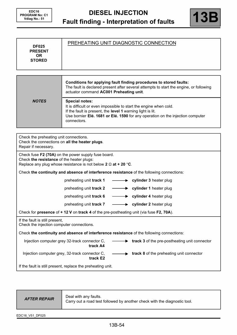
DIESEL INJECTIONFault finding - Interpretation of faults 13B
13B-54
EDC16PROGRAM No: C1
Vdiag No.: 51
DF025PRESENT
ORSTORED
PREHEATING UNIT DIAGNOSTIC CONNECTION
NOTES
Conditions for applying fault finding procedures to stored faults:The fault is declared present after several attempts to start the engine, or following actuator command AC001 Preheating unit.
Special notes:It is difficult or even impossible to start the engine when cold.If the fault is present, the level 1 warning light is lit.Use bornier Elé. 1681 or Elé. 1590 for any operation on the injection computer connectors.
Check the preheating unit connections.Check the connections on all the heater plugs.Repair if necessary.
Check fuse F2 (70A) on the power supply fuse board.Check the resistance of the heater plugs:Replace any plug whose resistance is not below 2 Ω at + 20 °C.
Check the continuity and absence of interference resistance of the following connections:
preheating unit track 1 cylinder 3 heater plug
preheating unit track 2 cylinder 1 heater plug
preheating unit track 6 cylinder 4 heater plug
preheating unit track 7 cylinder 2 heater plug
Check for presence of + 12 V on track 4 of the pre-postheating unit (via fuse F2, 70A).
If the fault is still present,Check the injection computer connections.
Check the continuity and absence of interference resistance of the following connections:
Injection computer grey 32-track connector C,track A4
track 3 of the pre-postheating unit connector
Injection computer grey, 32-track connector C,track E2
track 8 of the preheating unit connector
If the fault is still present, replace the preheating unit.
AFTER REPAIRDeal with any faults.Carry out a road test followed by another check with the diagnostic tool.
EDC16_V51_DF025
DIESEL INJECTIONFault finding - Interpretation of faults 13B
13B-55
EDC16PROGRAM No: C1
Vdiag No.: 51
DF037PRESENT
ORSTORED
ENGINE IMMOBILISER
NOTES
Conditions for applying the fault finding procedure to stored faults:The fault is declared present after an attempt to start engine.
Special notes:It is impossible to start the vehicle.If the fault is present, the level 2 warning light will light up.Use bornier Elé. 1681 or Elé. 1590 for any operation on the injection computer connectors.
Check the UCH connections.Check the injection computer connections.Repair if necessary.
Test the multiplex network (see 38B, Multiplexing) and carry out a complete fault finding on the UCH.Refer to the UCH Technical Note (see 87B, Passenger compartment connection unit) if the fault is displayed as present.If the fault is still present, contact the Techline.
AFTER REPAIRDeal with any faults.Carry out a road test followed by another check with the diagnostic tool.
EDC16_V51_DF037

DIESEL INJECTIONFault finding - Interpretation of faults 13B
13B-56
EDC16PROGRAM No: C1
Vdiag No.: 51
DF038 PRESENT
OR STORED
COMPUTER1.DEF : Permanent high signal2.DEF : Permanent low signal3.DEF : Configuration absent or incorrect4.DEF : Analogue/digital converter fault5.DEF : Dialogue disrupted6.DEF : EEPROM fault7.DEF : Watchdog Activation8.DEF : Signal outside upper limit10.DEF : Injector control11.DEF : Injector control condenser fault12.DEF : Injection fault under deceleration13.DEF : Initialisation error14.DEF : Open circuit or internal electronic fault.
NOTES
Conditions for applying fault finding procedures to stored faults:The fault is declared present after an attempted start, or with the engine running.
Special notes:If 6.DEF, 8.DEF, 12.DEF is present, the level 1 warning light is on.If one of the other faults is present, the level 2 warning light comes on.If 6.DEF is still present, the OBD warning light will come on after three consecutive driving cycles (starting + 5 seconds + switching off the ignition and waiting for 1 minute).Use bornier Elé. 1681 or Elé. 1590 for any operation on the injection computer connectors.
Priority when dealing with a number of faults:Deal with fault DF046 Battery voltage first if it is present or stored.
CO1.DEF to
8.DEF10.DEF12.DEF13.DEF
Check the injection computer connections and the continuity of all the supplies.Repair if necessary.Clear the faults.Switch off the ignition, wait 1 minute and switch the ignition on again.If the fault is still present, contact the Techline and complete the fault finding log.
AFTER REPAIRDeal with any faults.Carry out a road test followed by another check with the diagnostic tool.
EDC16_V51_DF038

DIESEL INJECTIONFault finding - Interpretation of faults 13B
DF038CONTINUED
11.DEF NOTESIf there are a number of faults, deal with the other system faults first.
Display the stored context for fault DF038.PR142 Computer fault = 10
NO YES
Main screen parametersPR071 Computer supply voltage > 10 V
YES
Contexts stored from DF038PR071 Computer supply voltage > 10 V
YES
Check the condition of the wiring harness between the computer and the battery, carry out the necessary repairs.– Start the vehicle.– Clear the stored faults.– Check the faults:– If DF038 is stored, end fault finding.– If DF038 is present, contact the Techline.
NO
Check the charge circuit and carry out the necessary repairs:– Check the condition of the battery
terminals.– Carry out fault finding on the alternator.Recharge or replace the battery.
13B-57
EDC16PROGRAM No: C1
Vdiag No.: 51
Contact the Techline.
AFTER REPAIRDeal with any faults.Carry out a road test followed by another check with the diagnostic tool.
DIESEL INJECTIONFault finding - Interpretation of faults 13B
13B-58
EDC16PROGRAM No: C1
Vdiag No.: 51
DF039 PRESENT
OR STORED
INLET AIR TEMPERATURE SENSOR CIRCUITCO.1 : Open circuit or short circuit to + 12 VCC.0 : Short circuit to earth
NOTES
Conditions for applying fault finding procedures to stored faults:The fault is declared present after an attempted start, or with the engine running.
Special notes:If the fault is present:– the air temperature value enters defect mode, i.e. PR059 Inlet air temperature =
20 °C.– the EGR function is inhibited,– the level 2 warning light is lit.Use bornier Elé. 1681 or Elé. 1590 for any operation on the injection computer connectors.
CO.1 NOTES None
Check the air flow sensor connections.Check the injection computer connections.Repair if necessary.Check the continuity of the following connection:
Injection supply relay mounting Track 5 track 4 air flow sensor connector
Repair if necessary.Check the continuity and insulation against + 12 V of the following connections:
Injection computer brown 48-track connector B,track G2
Track 1 air flow sensor connector
Injection computer brown 48-track connector B,track E2
Track 2 air flow sensor connector
Injection computer brown 48-track connector B,track B4
Track 3 air flow sensor connector
Injection computer brown 48-track connector B,track L4
Track 6 air flow sensor connector
Repair if necessary.
AFTER REPAIRDeal with any faults.Carry out a road test followed by another check with the diagnostic tool.
EDC16_V51_DF039

DIESEL INJECTIONFault finding - Interpretation of faults 13B
13B-59
EDC16PROGRAM No: C1
Vdiag No.: 51
DF039CONTINUED
Measure the air temperature sensor resistance between tracks 1 and 2 of the air flow sensor.Replace the air flow sensor if the resistance displayed is not:
3714 ± 161 Ω at 10 °C2448 ± 96 Ω at 20 °C1671 ± 59 Ω at 30 °C
CC.0 NOTES None
Check the air flow sensor connections.Check the injection computer connections.Repair if necessary.
Check the continuity and insulation against earth of the connection between:
Injection computer brown 48-track connector B,track G2
Track 1 air flow sensor connector
Injection computer brown 48-track connector B,track E2
Track 2 air flow sensor connector
Injection computer brown 48-track connector B,track B4
Track 3 air flow sensor connector
Injection supply relay mounting track 5 Track 4 air flow sensor connector
Repair if necessary.
Measure the air temperature sensor resistance between tracks 1 and 2 of the air flow sensor.Replace the air flow sensor if the resistance is not approximately:
3714 ± 161 Ω at 10 °C2448 ± 96 Ω at 20 °C1671 ± 59 Ω at 30 °C
AFTER REPAIRDeal with any faults.Carry out a road test followed by another check with the diagnostic tool.

DIESEL INJECTIONFault finding - Interpretation of faults 13B
13B-60
EDC16PROGRAM No: C1
Vdiag No.: 51
DF040PRESENT
ORSTORED
CYLINDER 1 INJECTOR CIRCUITCC.1 : Short circuit to + 12 VCO : Open circuitCC : Short circuit1.DEF: Injector control
NOTES
Conditions for applying fault finding procedures to stored faults:The fault is declared present after the engine has been started.
Special notes:If CC.1, CC, or 1.DEF is present, the level 2 warning light is lit.If CO is present the level 1 warning light is lit.If CO is still present, the OBD warning light will come on after three consecutive driving cycles (starting + 5 seconds + switching off the ignition and waiting for 1 minute).If the fault is present, the injection on cylinder 1 is disabled.Use bornier Elé. 1681 or Elé. 1590 for any operation on the injection computer connectors.
WARNINGThis fault may appear if the wiring harness has been damaged.Follow the procedure described in the Wiring Check in the Introduction.This test enables the condition and the conformity of the engine wiring harness to be checked.
CC.1COCC
1.DEF
NOTES None
Check the connections on injector no 1.Check the injection computer connections.Repair if necessary.
Disconnect injector no. 1.Measure the resistance of injector no. 1 between tracks 1 and 2.Replace the injector if there is a short circuit (R = 0 Ω) or an open circuit (resistance = infinity).Otherwise reconnect injector no. 1.
AFTER REPAIRDeal with any faults.Carry out a road test followed by another check with the diagnostic tool.
EDC16_V51_DF040

DIESEL INJECTIONFault finding - Interpretation of faults 13B
13B-61
EDC16PROGRAM No: C1
Vdiag No.: 51
DF040CONTINUED
Check the continuity and absence of interference resistance of the following connections:
Injection computer grey 32-track connector C,track G3
Track 2 injector no. 1
Injection computer grey 32-track connector C,track H1
Track 1 injector no. 1
If the fault is still present: apply test 8: POOR INJECTOR OPERATION.
If the fault is still present, contact the Techline.
AFTER REPAIRDeal with any faults.Carry out a road test followed by another check with the diagnostic tool.

DIESEL INJECTIONFault finding - Interpretation of faults 13B
13B-62
EDC16PROGRAM No: C1
Vdiag No.: 51
DF041PRESENT
ORSTORED
CYLINDER 2 INJECTOR CIRCUITCC.1 : Short circuit to + 12 VCO : Open circuitCC : Short circuit1.DEF: Injector control
NOTES
Conditions for applying fault finding procedures to stored faults:The fault is declared present after the engine has been started.
Special notes:If CC.1, CC, or 1.DEF is present, the level 2 warning light is lit.If CO is present the level 1 warning light is lit.If CO is still present, the OBD warning light will come on after three consecutive driving cycles (starting + 5 seconds + switching off the ignition and waiting for 1 minute).If the fault is present, the injection on cylinder 2 is disabled.Use bornier Elé. 1681 or Elé. 1590 for any operation on the injection computer connectors.
WARNINGThis fault may appear if the wiring harness has been damaged.Follow the procedure described in the Wiring Check in the Introduction.This test enables the condition and the conformity of the engine wiring harness to be checked.
CC.1COCC
1.DEF
NOTES None
Check the connections on injector no 2.Check the injection computer connections.Repair if necessary.
Disconnect injector no. 2.Measure the resistance of injector no. 2 between tracks 1 and 2.Replace the injector if there is a short circuit (R = 0 Ω) or an open circuit (resistance = infinity).Otherwise reconnect injector no. 2.
AFTER REPAIRDeal with any faults.Carry out a road test followed by another check with the diagnostic tool.
EDC16_V51_DF041

DIESEL INJECTIONFault finding - Interpretation of faults 13B
13B-63
EDC16PROGRAM No: C1
Vdiag No.: 51
DF041CONTINUED
Check the continuity and absence of interference resistance of the following connections:
Injection computer grey 32-track connector C,track G4
Track 2 injector no. 2
Injection computer grey 32-track connector C,track G2
Track 1 injector no. 2
If the fault is still present: apply test 8: POOR INJECTOR OPERATION.
If the fault is still present, contact the Techline.
AFTER REPAIRDeal with any faults.Carry out a road test followed by another check with the diagnostic tool.

DIESEL INJECTIONFault finding - Interpretation of faults 13B
13B-64
EDC16PROGRAM No: C1
Vdiag No.: 51
DF042PRESENT
ORSTORED
CYLINDER 3 INJECTOR CIRCUITCC.1 : Short circuit to + 12 VCO : Open circuitCC : Short circuit1.DEF: Injector control
NOTES
Conditions for applying fault finding procedures to stored faults:The fault is declared present after the engine has been started.
Special notes:If CC.1, CC, or 1.DEF is present, the level 2 warning light is lit.If CO is present the level 1 warning light is lit.If CO is still present, the OBD warning light will come on after three consecutive driving cycles (starting + 5 seconds + switching off the ignition and waiting for 1 minute).If the fault is present, the injection on cylinder 3 is disabled.Use bornier Elé. 1681 or Elé. 1590 for any operation on the injection computer connectors.
WARNINGThis fault may appear if the wiring harness has been damaged.Follow the procedure described in the Wiring Check in the Introduction.This test enables the condition and the conformity of the engine wiring harness to be checked.
CC.1COCC
1.DEF
NOTES None
Check the connections on injector no 3.Check the injection computer connections.Repair if necessary.
Disconnect injector no. 3.Measure the resistance of injector no. 3 between tracks 1 and 2.Replace the injector if there is a short circuit (R = 0 Ω) or an open circuit (resistance = infinity).Otherwise reconnect injector no. 3.
AFTER REPAIRDeal with any faults.Carry out a road test followed by another check with the diagnostic tool.
EDC16_V51_DF042
DIESEL INJECTIONFault finding - Interpretation of faults 13B
13B-65
EDC16PROGRAM No: C1
Vdiag No.: 51
DF042CONTINUED
Check the continuity and absence of interference resistance of the following connections:
Injection computer 32-track grey connector C,track H4
Track 2 injector no. 3
Injection computer grey 32-track connector C,track H2
Track 1 injector no. 3
If the fault is still present: apply test 8: POOR INJECTOR OPERATION.
If the fault is still present, contact the Techline.
AFTER REPAIRDeal with any faults.Carry out a road test followed by another check with the diagnostic tool.
DIESEL INJECTIONFault finding - Interpretation of faults 13B
13B-66
EDC16PROGRAM No: C1
Vdiag No.: 51
DF043PRESENT
ORSTORED
CYLINDER 4 INJECTOR CIRCUITCC.1 : Short circuit to + 12 VCO : Open circuitCC : Short circuit1.DEF: Injector control
NOTES
Conditions for applying fault finding procedures to stored faults:The fault is declared present after the engine has been started.
Special notes:If CC.1, CC, or 1.DEF is present, the level 2 warning light is lit.If CO is present the level 1 warning light is lit.If CO is still present, the OBD warning light will come on after three consecutive driving cycles (starting + 5 seconds + switching off the ignition and waiting for 1 minute).If the fault is present, the injection on cylinder 4 is disabled.Use bornier Elé. 1681 or Elé. 1590 for any operation on the injection computer connectors.
WARNINGThis fault may appear if the wiring harness has been damaged.Follow the procedure described in the Wiring Check in the Introduction.This test enables the condition and the conformity of the engine wiring harness to be checked.
CC.1COCC
1.DEF
NOTES None
Check the connections on injector no 4.Check the injection computer connections.Repair if necessary.
Disconnect injector no. 4.Measure the resistance of injector no. 4 between tracks 1 and 2.Replace the injector if there is a short circuit (R = 0 Ω) or an open circuit (resistance = infinity).Otherwise reconnect injector no. 4.
AFTER REPAIRDeal with any faults.Carry out a road test followed by another check with the diagnostic tool.
EDC16_V51_DF043

DIESEL INJECTIONFault finding - Interpretation of faults 13B
13B-67
EDC16PROGRAM No: C1
Vdiag No.: 51
DF043CONTINUED
Check the continuity and absence of interference resistance of the following connections:
Injection computer grey 32-track connector C,track H3
Track 2 injector no. 4
Injection computer grey 32-track connector C,track G1
Track 1 injector no. 4
If the fault is still present: apply test 8: POOR INJECTOR OPERATION.
If the fault is still present, contact the Techline.
AFTER REPAIRDeal with any faults.Carry out a road test followed by another check with the diagnostic tool.

DIESEL INJECTIONFault finding - Interpretation of faults 13B
13B-68
EDC16PROGRAM No: C1
Vdiag No.: 51
DF046PRESENT
ORSTORED
BATTERY VOLTAGE1.DEF: Excess voltage2.DEF: Undervoltage
NOTES
Conditions for applying fault finding procedures to stored faults:The fault is declared present following a road test or after attempting to start the engine.
Special notes:Computer operating voltage: 9 V < operating voltage < 16 V.Battery voltage that is too low can cause the level 1 fault warning light to come on thereby causing other faults to appear.It is then not possible to start the engine.Use bornier Elé. 1681 or Elé. 1590 for any operation on the injection computer connectors.
1.DEF NOTES None
Check the charge circuits:– Condition of the battery.– Condition of the alternator (full fault finding procedure).– Carry out the necessary repairs.
2.DEF NOTES None
With the ignition off, measure the voltage across the battery terminals.If the voltage is less than 11.5 V, test the battery.If the battery is faulty, replace the battery then test the charge circuit.With the ignition on and the with the starter motor turning, measure the voltage between the battery terminalsIf the voltage drops below 9.6 V, check the tightness and condition of the battery terminals.Repair if necessary.If the terminals are in good condition, test the battery.If they are faulty, replace the battery.If the starter is cranking the engine correctly, but the fault is still present,– Check the continuity and absence of interference resistance of the following connections:
+ 12 V Supply relay track 5 track M2 connector B of the engine management computer
track 4 of Protection and Switching Unit greyconnector
track G1 connector A of the engine management computer
Battery earth tracks G4, H4, H1 injection computer connector A
Repair if necessary.
AFTER REPAIRDeal with any faults.Carry out a road test followed by another check with the diagnostic tool.
EDC16_V51_DF046

DIESEL INJECTIONFault finding - Interpretation of faults 13B
13B-69
EDC16PROGRAM No: C1
Vdiag No.: 51
DF047PRESENT
ORSTORED
COMPUTER SUPPLY VOLTAGE1.DEF: Voltage outside permitted range of values
NOTES
Conditions for applying the fault finding procedure to stored faults:The fault is declared present after several starting attempts, or with the engine running.
Special notes:Computer operating voltage: 9 V < operating voltage < 16 V.Battery voltage that is too low can cause the level 1 fault warning light to come on thereby causing other faults to appear.Use bornier Elé. 1681 or Elé. 1590 for any operation on the injection computer connectors.
Check continuity and make sure there is no interference resistance on the following connection:
injection computer black 32-track connector A,track D1
track 1 of the Protection and Switching Unit black connector
Repair if necessary.
Check fuse F5D (5A) located on the UPC.Check the condition of the injection test unit supply relay (50A) located on the relay plate in the engine connection unit below the Protection and Switching Unit (no false contacts, or oxidation on the relay mounting clips).Repair if necessary.
If the fault does not recur, start the engine and wait 1 min.Carry out a road test and check the system faults.If there are no faults, fault finding is complete.If the fault is still present, contact the Techline.
AFTER REPAIRDeal with any faults.Carry out a road test followed by another check with the diagnostic tool.
EDC16_V51_DF047
DIESEL INJECTIONFault finding - Interpretation of faults 13B
13B-70
EDC16PROGRAM No: C1
Vdiag No.: 51
DF049PRESENT
OR STORED
REFRIGERANT SENSOR CIRCUITCC.1 : Short circuit to + 12 VCO.0 : Open circuit or short circuit to earth
NOTES
Conditions for applying fault finding procedures to stored faults:The fault is declared present following a road test, or if the air conditioning is switched on.
Special notes:If the fault is present, air conditioning is not authorised.Use bornier Elé. 1681 or Elé. 1590 for any operation on the injection computer connectors.
CC.1 NOTES None
Check the refrigerant pressure sensor connectors.Check the injection computer connections.Repair if necessary.
Check that the configuration reading LC009 Air conditioning is WITH.If LC009 is WITHOUT, run command RZ005 Programming to reinitialise the vehicle configurations.If necessary, operate the air conditioning to reconfigure the computer to WITH.Connect an air conditioning filling station (equipped with a high pressure gauge) to the vehicle.Display parameter PR037 Refrigerant pressure and compare the value displayed by the filling station.If the values match, run fault finding on the air conditioning (see 62A, Air conditioning).
If the values do not match, check the continuity and insulation against + 12 V of the following connections:
Injection computer brown 48-track connector B,track F1
Track C refrigerant sensor connector
Injection computer brown 48-track connector B,track F3
Track B refrigerant sensor connector
Injection computer grey 32-track connector C,track C3
Track A refrigerant sensor connector
Repair if necessary.
If the fault is still present, replace the refrigerant pressure sensor.
AFTER REPAIRDeal with any faults.Carry out a road test followed by another check with the diagnostic tool.
EDC16_V51_DF049

DIESEL INJECTIONFault finding - Interpretation of faults 13B
13B-71
EDC16PROGRAM No: C1
Vdiag No.: 51
DF049CONTINUED
CO.0 NOTES None
Check the refrigerant pressure sensor connectors.Check the injection computer connections.Repair if necessary.Check that the configuration reading LC009 Air conditioning is WITH.If LC009 is WITHOUT, run command RZ005 Programming to reinitialise the vehicle configurations.If necessary, operate the air conditioning to reconfigure the computer to WITH.Connect an air conditioning filling station (equipped with a high pressure gauge) to the vehicle.Display parameter PR037 Refrigerant pressure and compare the value displayed by the filling station.If the values match, carry out a fault finding procedure as described in the fault finding note for that vehicle.
If the values do not match, check the continuity and insulation against earth of the following connections:
Injection computer brown 48-track connector B,track F1
Track C refrigerant sensor connector
Injection computer brown 48-track connector B,track F3
Track B refrigerant sensor connector
Repair if necessary.
If the fault is still present, replace the refrigerant pressure sensor.
AFTER REPAIRDeal with any faults.Carry out a road test followed by another check with the diagnostic tool.

DIESEL INJECTIONFault finding - Interpretation of faults 13B
13B-72
EDC16PROGRAM No: C1
Vdiag No.: 51
DF050PRESENT
ORSTORED
BRAKE SWITCH CIRCUIT1.DEF: Open circuit or short circuit2.DEF: Signal incoherence
NOTES
Conditions for applying fault finding procedures to stored faults:The fault is declared present after the brake pedal is depressed, or during a road test.
Special notes:If the fault is present, the cruise control/speed limiter is deactivated.Use bornier Elé. 1681 or Elé. 1590 for any operation on the injection computer connectors.
WARNINGThis fault may appear if the wiring harness has been damaged.Follow the procedure described in the Wiring Check in the Introduction.This check enables the condition and the conformity of the engine wiring harness to be checked.
1.DEF NOTES None
Check the brake pedal switch connections.Check the condition and adjustment of the brake pedal switch.Repair if necessary.
Check the conformity of the brake light switch:
Brake pedal released:continuity between tracks 3 and 4infinite resistance across tracks 1 and 2
Brake pedal depressed:infinite resistance between tracks 3 and 4continuity between tracks 1 and 2.
AFTER REPAIRDeal with any faults.Carry out a road test followed by another check with the diagnostic tool.
EDC16_V51_DF050
DIESEL INJECTIONFault finding - Interpretation of faults 13B
13B-73
EDC16PROGRAM No: C1
Vdiag No.: 51
DF050CONTINUED
Replace the switch if necessary.Check the condition of fuse H 15A on the passenger compartment fuse and relay plate.Replace the fuse if necessary.Check the feeds to the switch:
+ 12 V after ignition feed track 2 of the brake pedal switch connector
+ 12 V battery feed track 4 of the brake pedal switch connector (via the UCH)
Replace the switch if necessary.Check the continuity and insulation of the following connections:
Injection computer black 32-trackconnector A, track E4
Track 3 of the brake pedal switch connector
Repair if necessary.
2.DEF NOTES None
Check the brake pedal switch connections.Check the condition and adjustment of the brake pedal switch.Repair if necessary.
Check the continuity and make sure there is no interference resistance on the following connection:
Injection computer black 32-track connector Atrack E4
Track 3 of the brake switch
Repair if necessary.Check the conformity of the switch by consulting the interpretation of statuses ET122 Brake contact no. 1 signal and ET123 Brake contact no. 2 signal.If the fault is still present, carry out fault finding on the ABS computer.
AFTER REPAIRDeal with any faults.Carry out a road test followed by another check with the diagnostic tool.
DIESEL INJECTIONFault finding - Interpretation of faults 13B
13B-74
EDC16PROGRAM No: C1
Vdiag No.: 51
DF051 PRESENT
OR STORED
CRUISE CONTROL/SPEED LIMITER FUNCTION1.DEF: Signal incoherence2.DEF: Inconsistent vehicle speed3.DEF: Steering wheel controls
NOTES
Conditions for applying fault finding procedures to stored faults:The fault is declared present after the engine is started or following a road test.
Special notes:The cruise control/speed limiter function is inhibited.Use bornier Elé. 1681 or Elé. 1590 for any operation on the injection computer connectors.
WARNINGThis fault may appear if the wiring harness has been damaged.Follow the procedure described in the Wiring Check in the Introduction.This check enables the condition and the conformity of the engine wiring harness to be checked.
If the fault is declared present, refer to the section of the conformity check on the Cruise control/Speed limiter, and to the interpretation of statuses:ET042 Cruise control/speed limiter.ET413 Cruise control/speed limiter function.ET556 Driver deactivation of the cruise control/speed limiter.ET557 Cruise control/speed limiter deactivation by function.
Check that by pressing the buttons the statuses change and that, with the ignition switched on, all the values are correct.
If the fault is still present, contact the Techline.
AFTER REPAIRDeal with any faults.Carry out a road test followed by another check with the diagnostic tool.
EDC16_V51_DF051

DIESEL INJECTIONFault finding - Interpretation of faults 13B
13B-75
EDC16PROGRAM No: C1
Vdiag No.: 51
DF053 PRESENT
OR STORED
RAIL PRESSURE REGULATION FUNCTIONCC.1 : Short circuit to + 12 VCC.0 : Short circuit to earthCO : Open circuit1.DEF: Internal electronic fault2.DEF: Measured pressure too low3.DEF: Measured pressure too high4.DEF: Insufficient pressure5.DEF: Pressure < minimum6.DEF: Pressure > maximum7.DEF: Extensive pump command
NOTES
Conditions for applying fault finding procedures to stored faults:The fault appears after:– the engine is started,– a road test,– an actuator command AC011 Rail pressure regulator.
Special notes:If the fault is present:– it is not possible to start the engine.– engine stops if already started,– if 3.DEF is present, the level 1 warning light is lit,– if one of the other faults is present, the level 2 warning light comes on.Use bornier Elé. 1681 or Elé. 1590 for any operation on the injection computer connectors.
CC.1 NOTES None
Check the rail pressure regulator connectors.Check the injection computer connections.Check the low pressure circuit and that the correct fuel is being used using test 2.Repair if necessary.
Measure the resistance of the rail pressure regulator between tracks 1 and 2.If the resistance is not 3 Ω ± 0.1 at 20 °C, replace the rail pressure regulator.Check the continuity and insulation from the + 12 V feed of the following connection:
Injection computer brown 48-track connector B,track M4
Track 2 of the rail pressure regulator (fuel flow actuator)
Check the rail pressure sensor using the interpretation of DF007 Rail pressure sensor circuit.If the fault is still present replace the rail pressure regulator.
AFTER REPAIRDeal with any faults.Carry out a road test followed by another check with the diagnostic tool.
EDC16_V51_DF053

DIESEL INJECTIONFault finding - Interpretation of faults 13B
13B-76
EDC16PROGRAM No: C1
Vdiag No.: 51
DF053CONTINUED 1
CC.0CO
NOTES None
Check the rail pressure regulator connectors.Check the injection computer connections.Check the low pressure circuit and that the correct fuel is being used using test 2.Repair if necessary.
Measure the resistance of the rail pressure regulator between tracks 1 and 2.If the resistance is not 3 Ω ± 0.1 at 20 °C, replace the rail pressure regulator.Check the continuity, and insulation from earth of the following connection:
Injection computer brown 48-trackconnector B, track M4
Track 2 of the rail pressure regulator (fuel flow actuator)
With the ignition on, check for + 12 V after relay on track 1 of the rail pressure regulator.If there is not + 12 V on track 1, check the continuity and absence of interference resistance of the following connection:
Rail pressure regulator track 1 Injection supply relay track 5
Repair if necessary.
Check the rail pressure sensor using the interpretation of DF007 Rail pressure sensor circuit.If the fault is still present replace the rail pressure regulator.
AFTER REPAIRDeal with any faults.Carry out a road test followed by another check with the diagnostic tool.

DIESEL INJECTIONFault finding - Interpretation of faults 13B
13B-77
EDC16PROGRAM No: C1
Vdiag No.: 51
*Opening Cyclic Ratio
DF053CONTINUED 2
1.DEF NOTES None
Check the rail pressure regulator connectors.Check the injection computer connections.Check the low pressure circuit and that the correct fuel is being used using test 2.Repair if necessary.
Measure the resistance of the pressure regulator between its tracks 1 and 2.If the resistance is not 3 Ω ± 0.1 at 20 °C, replace the rail pressure regulator.Check the continuity and absence of interference resistance of the following connections:
Injection computer brown 48-trackconnector B, track M4
track 2 of the rail pressure regulator (fuel flow actuator)
Injection supply relay track 5 track 1 of the rail pressure regulator (fuel flow actuator)
Repair if necessary.Check the rail pressure sensor using the interpretation of DF007 Rail pressure sensor circuit.Repair if necessary.
If the fault is still present, check that the computer output is working correctly. Either using an ammeter:With the regulator connected, connect the current clamp to the regulator's track 1 connection, respecting the direction of the current.Clear any rail pressure sensor faults and use command AC011 Rail pressure regulator.The ammeter should display ten cycles of two successive currents: ~ 0.6A then ~ 2A.
Using a voltmeter:With the regulator connected, connect the negative terminal of the voltmeter to track 2 of the rail pressure regulator and the positive terminal to track 1. Clear any fuel pressure solenoid valve faults, then run command AC011 Rail pressure regulator:The voltmeter should display two successive voltage readings:~ 3.15 volts for an opening cycle ratio of 25 % then ~ 9.45 V for an opening cycle ratio of 75 % (ten cycles).
Or using an oscilloscope (at 5 V range/division and 1 ms/div time base):With the regulator connected, connect the negative terminal of the oscilloscope to the battery earth and the positive terminal to track 2 of the fuel pressure solenoid valve, clear any rail pressure regulator faults, and run command AC011 Rail pressure regulator:
The oscilloscope should display a square wave signal with an amplitude of 12.5 V at a frequency of 185 Hz (with an OCR alternating from 25 to 75 %).If the measurement does not show any control or continuous voltage, contact the Techline.
AFTER REPAIRDeal with any faults.Carry out a road test followed by another check with the diagnostic tool.

DIESEL INJECTIONFault finding - Interpretation of faults 13B
DF053CONTINUED 3
2.DEF to7.DEF
NOTES None
Check the rail pressure regulator connectors.Check the injection computer connections.Check the low pressure circuit and that the correct fuel is being used using test 2.Repair if necessary.
Measure the resistance of the pressure regulator between its tracks 1 and 2.If the resistance is not 3 Ω ± 0.1 at 20 °C, replace the rail pressure regulator.Check the continuity and for the absence of interference resistance on the following connections:
Injection computer brown 48-trackconnector B, track M4
track 2 of the rail pressure regulator
Injection supply relay track 5 track 1 of the rail pressure regulator
Repair if necessary.
In the event of rail overpressure:
Check the operation of the injectors: refer to test 8: POOR INJECTOR OPERATION.Check that the rail pressure sensor is operating correctly using command AC011 Rail pressure regulator. Display parameter PR038 Rail pressure, and refer to the conformity check to check the operating values.If these checks do not reveal any faults, and if the fault is still present, replace the rail pressure sensor.
In the event of rail underpressure:
Check that the rail pressure sensor is operating correctly using command AC011 Rail pressure regulator. Display parameter PR038 Rail pressure, and refer to the conformity check to check the operating values.Check the low pressure diesel circuit priming.Check the conformity of the diesel filter connections.Check the condition of the filter (clogging and water saturation).Check that there are no air bubbles between the filter and the high pressure pump.Check the low and high pressure diesel fuel circuit sealing (visual inspections, odour, etc.): pump housing, pressure relief valve, pipes, rail and injector unions, injector wells, etc.Check the conformity of the seal fitting on the pressure regulator.Check the operation of the injectors: refer to test 8: POOR INJECTOR OPERATION.Carry out the necessary operations.
If the fault is still present replace the rail pressure regulator.
AFTER REPAIRDeal with any faults.Carry out a road test followed by another check with the diagnostic tool.
13B-78
EDC16PROGRAM No: C1
Vdiag No.: 51

DIESEL INJECTIONFault finding - Interpretation of faults 13B
13B-79
EDC16PROGRAM No: C1
Vdiag No.: 51
DF054PRESENT
ORSTORED
TURBOCHARGING SOLENOID VALVE CONTROL CIRCUITCC.1 : Short circuit to + 12 VCC.0 : Short circuit to earthCO : Open circuit1.DEF: Internal electronic fault2.DEF: Signal incoherence3.DEF: Below minimum threshold4.DEF: Above maximum threshold5.DEF: Permanent high level
NOTES
Conditions for applying the fault finding procedure to stored faults:The fault appears after:– the engine is started,– a road test,– actuator command AC004 Turbocharging solenoid valve.
Special notes:If the fault is present:– turbocharging is no longer authorised,– the EGR function is inhibited,– the vehicle performance is reduced,– the level 1 warning light is lit,– if CC.0 is present, the OBD warning light will come on after three consecutive driving
cycles (starting + 5 seconds + switching off the ignition and waiting for 1 minute).Use bornier Elé. 1681 or Elé. 1590 for any operation on the injection computer connectors.
CC.14.DEF5.DEF
NOTES None
Check the turbocharging solenoid valve connections.Check the injection computer connections.Repair if necessary.
Measure the resistance of the turbocharging solenoid valve between tracks 1 and 2:If the resistance displayed is not 15.4 Ω ± 0.7 at 20 °C, replace the turbocharger solenoid valve.
Check the continuity and insulation from the + 12 V feed of the following connection:
Injection computer grey 32-track connector C,track E1
Track 1 turbocharging solenoid valve
Repair if necessary.
If the fault is still present, replace the turbocharging solenoid valve.
AFTER REPAIRDeal with any faults.Carry out a road test followed by another check with the diagnostic tool.
EDC16_V51_DF054
DIESEL INJECTIONFault finding - Interpretation of faults 13B
13B-80
EDC16PROGRAM No: C1
Vdiag No.: 51
DF054CONTINUED 1
CC.0CO
3.DEFNOTES None
Check the turbocharging solenoid valve connections.Check the injection computer connections.Repair if necessary.
Measure the resistance of the turbocharging solenoid valve between tracks 1 and 2:If the resistance displayed is not 15.4 Ω ± 0.7 at 20 °C, replace the turbocharger solenoid valve.
Check the continuity and insulation to earth of the following connections:
Injection computer grey 32-trackconnector C, track E1
Track 1 turbocharging solenoid valve
UPC PPM1 connector Track 1 Track 2 turbocharger solenoid valve
Repair if necessary.
If the fault is still present, replace the turbocharging solenoid valve.
AFTER REPAIRDeal with any faults.Carry out a road test followed by another check with the diagnostic tool.

DIESEL INJECTIONFault finding - Interpretation of faults 13B
13B-81
EDC16PROGRAM No: C1
Vdiag No.: 51
*Opening Cyclic Ratio
DF054CONTINUED 2
1.DEF2.DEF
NOTES None
Check the turbocharging solenoid valve connections.Check the injection computer connections.Repair if necessary.
Measure the resistance of the turbocharging solenoid valve between tracks 1 and 2:If the resistance displayed is not 15.4 Ω ± 0.7 at 20 °C, replace the turbocharger solenoid valve.
Check the continuity and insulation to earth of the following connections:
Injection computer grey 32-trackconnector C, track E1
Track 1 turbocharging solenoid valve
UPC PPM1 connector Track 1 Track 2 Turbocharger solenoid valve
If the fault is still present, check that the computer output is working correctly.With the turbocharging solenoid valve connected:
Or using a voltmeter:– Connect the negative terminal of the voltmeter to track 1 of the solenoid valve and the negative terminal to
track 2.– Clear any solenoid valve faults and run command AC004 Turbocharger solenoid valve.
The voltmeter should display ten cycles of two successive voltages: ~ 2.5 V (opening cyclic ratio* of 20 %) then ~ 8.75 V (opening cyclic ratio* of 70 %).
Or using an oscilloscope (at 5 V range/division and 1 ms/div time base):– Connect the negative terminal of the oscilloscope to the battery earth and the positive terminal to track 2 of the
solenoid valve.– Clear any solenoid valve faults and run command AC004 Turbocharger solenoid valve.
The oscilloscope should display a square wave signal with an amplitude of 12.5 V (~ battery voltage) at a frequency of 140 Hz (with an OCR changing successively from ~ 20 to ~ 70 %).– If the measurement is correct, replace the solenoid valve.– If the measurement does not show any control or continuous voltage, contact the Techline.
AFTER REPAIRDeal with any faults.Carry out a road test followed by another check with the diagnostic tool.

DIESEL INJECTIONFault finding - Interpretation of faults 13B
13B-82
EDC16PROGRAM No: C1
Vdiag No.: 51
DF055 PRESENT
OR STORED
TURBOCHARGING PRESSURE REGULATION CIRCUIT1.DEF: Pressure too low2.DEF: Pressure too high
NOTES
Conditions for applying fault finding procedures to stored faults:The fault is declared present after the engine is started or following a road test.
Special notes:If the fault is present:– turbocharging is no longer authorised,– the EGR function is inhibited,– the level 1 warning light is lit.Use bornier Elé. 1681 or Elé. 1590 for any operation on the injection computer connectors.
1.DEF NOTES None
Check the turbocharger pressure sensor connections.Check the connections of the turbocharging pressure relief solenoid valve.Check the injection computer connections.Repair if necessary.
Check the sealing of the high pressure air circuit:– disconnected or pierced pipes,– pressure sensor disconnected or poorly fitted (seal present),– intercooler pierced (to check the intercooler: with the vehicle stationary, stabilise the engine speed between
3,500 and 4,000 rpm and check that there are no leaks).Check the conformity of the turbocharging pressure signal and apply tests 5 and 6.
AFTER REPAIRDeal with any faults.Carry out a road test followed by another check with the diagnostic tool.
EDC16_V51_DF055
DIESEL INJECTIONFault finding - Interpretation of faults 13B
13B-83
EDC16PROGRAM No: C1
Vdiag No.: 51
DF055CONTINUED 1
Check that the turbocharger and the control circuit are working:– With the engine stopped, make sure that the control rod is in the rest position.– Start the engine and make sure that the control rod actuates to the upper stop.(when the engine stops, the control rod should return to the rest position).If the control rod does not move correctly, carry out the following checks:1 Check the control vacuum pressure:– disconnect the solenoid valve inlet hose and connect it to a pressure gauge,– start the engine and stabilise it at idle speed,– If the vacuum does not reach 800 mbar ± 100: check the vacuum pressure circuit from the vacuum pump,– stop the engine, reconnect the inlet hose and proceed to step 2.2 Solenoid valve control check:– Disconnect the solenoid valve outlet hose,– start the engine and stabilise it at idle speed,– place your hand on the solenoid valve and block the outlet connection with your thumb,– if there is no detectable vibration of the solenoid valve, check that the computer output is operating correctly (see
DF054 Turbocharging solenoid valve control circuit 1.DEF).3 Solenoid valve operation check:– Attach the pressure gauge to the solenoid valve outlet union,– start the engine and stabilise it at idle speed,– if the vacuum pressure does not reach 800 mbar ± 100, replace the solenoid valve.
AFTER REPAIRDeal with any faults.Carry out a road test followed by another check with the diagnostic tool.
DIESEL INJECTIONFault finding - Interpretation of faults 13B
13B-84
EDC16PROGRAM No: C1
Vdiag No.: 51
DF055CONTINUED 2
2.DEF NOTESPriority when dealing with a number of faults:Deal with fault DF004 Turbocharger pressure sensor circuit first if it is present or stored.
Check the turbocharging pressure sensor connections,Check the connections of the turbocharging solenoid valve,Check the injection computer connections. Repair if necessary.
Check the conformity of the turbocharging pressure signal (refer to the interpretation of parameter PR041 Turbocharging pressure).
Make sure the turbocharging pressure relief solenoid valve is not jammed open:– With the engine switched off, disconnect the inlet and outlet hoses from the solenoid valve.– connect a vacuum pump to the inlet union and apply a vacuum pressure.– if the vacuum pressure is not maintained: replace the solenoid valve.
Check that the turbocharger control rod has not seized:– with the engine stopped, make sure the turbocharger control rod is in the rest position.– apply a vacuum pressure of 800 mbar ± 100, to the hose connected to the turbocharger control diaphragm,– if the diaphragm is affected by the vacuum, check the movement and setting of the turbocharger control rod (See
MR 364, Mechanical, 12B, Turbocharging).If the control rod is seized, replace the turbocharger.If the fault is still present, run tests 5 and 6.
AFTER REPAIRDeal with any faults.Carry out a road test followed by another check with the diagnostic tool.
DIESEL INJECTIONFault finding - Interpretation of faults 13B
13B-85
EDC16PROGRAM No: C1
Vdiag No.: 51
DF056 PRESENT
OR STORED
AIR FLOW SENSOR CIRCUITCC.1 : Short circuit to + 12 VCO.0 : Open circuit or short circuit to earth1.DEF: Offset at maximum threshold2.DEF: Offset at minimum threshold
NOTES
Conditions for applying fault finding procedures to stored faults:The fault is declared present after a road test.
Special notes:If the fault is present:– the level 1 warning light is lit,– the OBD warning light will illuminate after three consecutive driving cycles (starting
+ 5 seconds + switching off the ignition and waiting 1 minute).Use bornier Elé. 1681 or Elé. 1590 for any operation on the injection computer connectors.
Priorities when dealing with a number of faults:Deal with fault DF013 Sensor supply voltage no. 3 first, if it is present or stored.
CC.1 NOTES None
Check the air flow sensor connections.Check the injection computer connections.Repair if necessary.
Check the continuity and the insulation to + 12 V of the following connections:
Injection computer brown 48-track connector B,track E2
Track 2 of the air flow sensor
Injection computer brown 48-track connector B,track L4
Track 6 of the air flow sensor
Injection computer brown 48-track connector B,track G1
Track 5 of the air flow sensor
Injection computer brown 48-track connector B,track B4
Track 3 of the air flow sensor
If the fault is still present, replace the air flow sensor.
AFTER REPAIRDeal with any faults.Carry out a road test followed by another check with the diagnostic tool.
EDC16_V51_DF056

DIESEL INJECTIONFault finding - Interpretation of faults 13B
13B-86
EDC16PROGRAM No: C1
Vdiag No.: 51
DF056CONTINUED 1
CO.0 NOTES None
Check there is a + 5 V supply on track 3 of the air flow sensor.Repair if necessary.Check the air flow sensor connections.Check the injection computer connections.Repair if necessary.
Check the continuity and insulation to earth between:
Injection computer brown 48-track connector B,track E2
Track 2 of the air flow sensor
Injection computer brown 48-track connector B,track B4
Track 3 of the air flow sensor
Injection computer brown 48-track connector B,track G1
Track 5 of the air flow sensor
UPC black connector Track 2 Track 4 of the air flow sensor
Repair if necessary.If the fault is still present and remains present, replace the air flow sensor.
AFTER REPAIRDeal with any faults.Carry out a road test followed by another check with the diagnostic tool.
DIESEL INJECTIONFault finding - Interpretation of faults 13B
13B-87
EDC16PROGRAM No: C1
Vdiag No.: 51
DF056CONTINUED 2
1.DEF
NOTES
None
2.DEF
Conditions for applying fault finding procedures to stored faults:The fault is declared present after the ignition has been switched off for 1 minute.
Check the air flow sensor connections.Check the injection computer connections.Repair if necessary
Check the following connections for continuity and make sure there is no interference resistance:
injection computer, brown 48-track connector B,track B4
Track 3 of the air flow sensor
Injection computer brown 48-track connector B,track G1
Track 5 of the air flow sensor
Injection computer 48-track brown connector Btrack L4
Track 6 of the air flow sensor
Injection computer, brown 48-track connector Btrack E2
Track 2 of the air flow sensor
UPC black connector Track 2 Track 4 of the air flow sensor
Repair if necessary.
If the fault is still present, apply test 3: Checking the turbocharged air inlet circuit and test 4: Air flow sensor,– check that the damper valve is open (valve control pushing on the body of the air vent unit)– with the flow sensor connected, the vehicle ignition on and engine stopped:– check the voltage between tracks 2 and 5 of the air flow sensor:
If the value is not 0.6 V ±±±± 0.1, replace the air flow sensor.
Check the EGR valve is not jammed open:– Deal with any faults.– Use the conformity check and EMISSION CONTROL/OBD sub-function.– Apply test 7: Exhaust gas recirculation valve.If these checks show that the valve is jammed or irrevocably seized, replace the EGR valve.If no faults are revealed, but the fault is still present, replace the air flow sensor.
AFTER REPAIRDeal with any faults.Carry out a road test followed by another check with the diagnostic tool.
DIESEL INJECTIONFault finding - Interpretation of faults 13B
13B-88
EDC16PROGRAM No: C1
Vdiag No.: 51
DF057PRESENT
ORSTORED
WATER IN DIESEL FUEL DETECTOR CIRCUIT
NOTESConditions for applying fault finding procedures to stored faults:The fault is declared present after the engine is started or following a road test.
Check the conformity and quality of the fuel.Check the sealing of the reservoir and the low pressure circuit by applying test 2.
A) Make sure the water detection sensor is properly connected.– If not, clear the fault,– Carry out a road test (speed > 12 mph (20 km/h) and engine speed > 1200 rpm) for more than 30 seconds.– If the fault does not recur, end the fault finding procedure.– If the fault does recur, go to step C.
B) If the water detection sensor is absent:– Insulate the electrical connector not connected to the vehicle (risk of dampness, oxidation, and erratic
appearance of faults).Check that the configuration reading LC065 Water detected in the diesel is NONE.If LC065 is WITH, run command RZ005 Programming to reinitialise the vehicle configurations.
– Clear the faults.– Carry out a road test (speed > 12 mph (20 km/h) and engine speed > 1200 rpm) for more than 30 seconds.– If the fault does not recur, end the fault finding procedure.
C) If the sensor is properly connected:– Bleed the diesel filter unit (see MR 364, Mechanics, 13A, Fuel supply).– Clear the fault.– Carry out a road test (speed > 12 mph (20 km/h) and engine speed > 1200 rpm) for more than 30 seconds.– If the fault does not recur, end the fault finding procedure.D) If the fault recurs:– Check for continuity and the absence of interference resistance on the connection between:
Injection computer 32-track grey connectortrack A2
Track 3 of the water detection sensor
AFTER REPAIRDeal with any faults.Carry out a road test followed by another check with the diagnostic tool.
EDC16_V51_DF057
DIESEL INJECTIONFault finding - Interpretation of faults 13B
13B-89
EDC16PROGRAM No: C1
Vdiag No.: 51
DF057CONTINUED
Check the power supply to the water detection sensor:
+ 12 V after relay track 1 water detection sensor
earth track 2 water detection sensor
Carry out the necessary repairs.If none of these checks reveal any faults:– Replace the water detection sensor (see MR 364, Mechanics, 13A, Fuel supply).– Clear the fault.– Carry out a road test (speed > 12 mph (20 km/h) and engine speed > of 1200 rpm) for more than 30 seconds,
to confirm the repair.
Note:If the level of water in the fuel filter unit is lower than the two electrodes on the sensor, certain driving conditions (on a bend, leaning) may cause the injection warning light to light up erratically.
AFTER REPAIRDeal with any faults.Carry out a road test followed by another check with the diagnostic tool.

DIESEL INJECTIONFault finding - Interpretation of faults 13B
13B-90
EDC16PROGRAM No: C1
Vdiag No.: 51
DF059 PRESENT
OR STORED
COMBUSTION MISFIRES ON CYLINDER 1
NOTES
Conditions for applying fault finding procedures to stored faults:The fault is declared present after the engine is started or following a road test.
Special notes:If the fault is present, engine performance is reduced and engine instabilities may occur.
Priority when dealing with a number of faults:Deal with fault DF040 Cylinder 1 injector circuit first, if it is present or stored.
Check that the injector no. 1 IMA code has been entered correctly and that it matches the code marked on the corresponding injector.Enter the code to the unprogrammed/incorrectly programmed injector, if necessary.Refer to the interpretation of commands, SC002 Entering injector codes.
Check the engine compression.Repair if necessary.
Check the valve clearance and adjust if necessary.
In the event of several combustion misfiring faults being present, check that the right fuel is being used
Visually inspect the return pipe of injector no. 1.Repair if necessary.
If the fault is still present, apply test 8: POOR INJECTOR OPERATION.If the fault is still present, contact the Techline.
AFTER REPAIRDeal with any faults.Carry out a road test followed by another check with the diagnostic tool.
EDC16_V51_DF059
DIESEL INJECTIONFault finding - Interpretation of faults 13B
13B-91
EDC16PROGRAM No: C1
Vdiag No.: 51
DF060PRESENT
ORSTORED
COMBUSTION MISFIRES ON CYLINDER 2
NOTES
Conditions for applying fault finding procedures to stored faults:The fault is declared present after the engine is started or following a road test.
Special notes:If the fault is present, engine performance is reduced and engine instabilities may occur.
Priority when dealing with a number of faults:Deal with fault DF041 Cylinder 2 injector circuit first, if it is present or stored.
Check that the injector no. 2 IMA code has been entered correctly and that it matches the code marked on the corresponding injector.Enter the code to the unprogrammed/incorrectly programmed injector, if necessary.Consult the interpretation of commands, SC002 Entering injector codes.
Check the engine compression.Repair if necessary.
Check the valve clearance and adjust if necessary.
In the event of several combustion misfiring faults being present, check that the right fuel is being used
Visually inspect the return pipe of injector no. 2.Repair if necessary.
If the fault is still present, apply test 8: POOR INJECTOR OPERATION.If the fault is still present, contact the Techline.
AFTER REPAIRDeal with any faults.Carry out a road test followed by another check with the diagnostic tool.
EDC16_V51_DF060

DIESEL INJECTIONFault finding - Interpretation of faults 13B
13B-92
EDC16PROGRAM No: C1
Vdiag No.: 51
DF061PRESENT
OR STORED
COMBUSTION MISFIRES ON CYLINDER 3
NOTES
Conditions for applying fault finding procedures to stored faults:The fault is declared present after the engine is started or following a road test.
Special notes:If the fault is present, engine performance is reduced and engine instabilities may occur.
Priority when dealing with a number of faults:Deal with fault DF042 Cylinder 3 injector circuit first, if it is present or stored.
Check that the injector no. 3 IMA code has been entered correctly and that it matches the code marked on the corresponding injector.Enter the code to the unprogrammed/incorrectly programmed injector, if necessary.Consult the interpretation of commands, SC002 Entering injector codes.
Check the engine compression.Repair if necessary.
Check the valve clearance and adjust if necessary.
In the event of several combustion misfiring faults being present, check that the right fuel is being used
Visually inspect the return pipe of injector no. 3.Repair if necessary.
If the fault is still present, apply test 8: POOR INJECTOR OPERATION.If the fault is still present, contact the Techline.
AFTER REPAIRDeal with any faults.Carry out a road test followed by another check with the diagnostic tool.
EDC16_V51_DF061

DIESEL INJECTIONFault finding - Interpretation of faults 13B
13B-93
EDC16PROGRAM No: C1
Vdiag No.: 51
DF062 PRESENT
OR STORED
COMBUSTION MISFIRES ON CYLINDER 4
NOTES
Conditions for applying fault finding procedures to stored faults:The fault is declared present after the engine is started or following a road test.
Special notes:If the fault is present, engine performance is reduced and engine instabilities may occur.
Priority when dealing with a number of faults:Deal with fault DF043 Cylinder 4 injector circuit first, if it is present or stored.
Check that the injector no. 4 IMA code has been entered correctly and that it matches the code marked on the corresponding injector.Enter the code to the unprogrammed/incorrectly programmed injector, if necessary.Consult the interpretation of commands, SC002 Entering injector codes.
Check the engine compression.Repair if necessary.
Check the valve clearance and adjust if necessary.
In the event of several combustion misfiring faults being present, check that the right fuel is being used
Visually inspect the return pipe of injector no. 4.Repair if necessary.
If the fault is still present, apply test 8: POOR INJECTOR OPERATION.If the fault is still present, contact the Techline.
AFTER REPAIRDeal with any faults.Carry out a road test followed by another check with the diagnostic tool.
EDC16_V51_DF062
DIESEL INJECTIONFault finding - Interpretation of faults 13B
13B-94
EDC16PROGRAM No: C1
Vdiag No.: 51
DF069PRESENT
ORSTORED
IMPACT DETECTED SIGNAL1.DEF: Impact stored by the injection computer
NOTES
Conditions for applying the fault finding procedure to stored faults:Only apply the procedure if the fault is present and if the vehicle does not start.
Special notes:The fault appears when the injection computer receives a frontal impact signal from the Airbag computer via the multiplex network.As soon as the injection computer receives this signal:– engine operation is prohibited,– the level 2 warning light is lit.Use bornier Elé. 1681 or Elé. 1590 for any operation on the injection computer connectors.
If the vehicle has been involved in an accident:
Carry out any necessary repairs,– clear the fault,– switch off the ignition,– wait for 1 minute,– switch on the ignition,
If the fault does not recur, end the fault finding procedure.If the fault recurs, carry out fault finding on the AIRBAG computer.
If the vehicle has not been involved in an accident:
Run fault finding on the AIRBAG computer
AFTER REPAIRDeal with any faults.Carry out a road test followed by another check with the diagnostic tool.
EDC16_V51_DF069

DIESEL INJECTIONFault finding - Interpretation of faults 13B
13B-95
EDC16PROGRAM No: C1
Vdiag No.: 51
DF070 PRESENT
OR STORED
CLUTCH SWITCH CIRCUIT1.DEF : No signal2.DEF : Signal incoherence
NOTES
Conditions for applying the fault finding procedure to stored faults:The fault is declared present after the clutch pedal is depressed, or during a road test.
Special notes:If this fault is present, the cruise control/speed limiter function will be inhibited.Use bornier Elé. 1681 or Elé. 1590 for any operation on the injection computer connectors.
WARNINGThis fault may appear if the wiring harness has been damaged.Follow the procedure described in the Wiring Check in the Introduction.This check enables the condition and the conformity of the engine wiring harness to be checked.
Check the conformity of the clutch switch setting (position, connection).– Display status ET233 Clutch pedal:– when the clutch pedal engaged, status ET233 should be RELEASED– when the clutch is disengaged, status ET233 should be DEPRESSED.if these checks are not correct, replace the clutch switch.
If the check show the correct results:Check the connections of the clutch pedal switch.Check the injection computer connections.Repair if necessary.
Check continuity and make sure there is no interference resistance on the following connection:
Injection computer, black 32- track connector A,track C4
Track 1 clutch pedal switch
Repair if necessary.Check for the presence of earth on track 2 of the clutch pedal switch.Repair if necessary.If the fault is still present, contact the Techline.
AFTER REPAIRDeal with any faults.Carry out a road test followed by another check with the diagnostic tool.
EDC16_V51_DF070

DIESEL INJECTIONFault finding - Interpretation of faults 13B
13B-96
EDC16PROGRAM No: C1
Vdiag No.: 51
DF086 PRESENT
OR STORED
COOLANT PUMP RELAY CONTROL CIRCUITCO.0 : Open circuit or short circuit to earthCC.1 : Short circuit to + 12 V
NOTES
Conditions for applying the fault finding procedure to stored faults:The fault is declared present after the ignition is switched off and after a wait of 1 minute, or following a AC195 Electric coolant pump actuator command.
Special notes:The control relay is located in the engine compartment connection unit.If the fault is present:– the EGR function is inhibited,– the level 1 warning light is lit.Use bornier Elé. 1681 or Elé. 1590 for any operation on the injection computer connectors.
CO.0 NOTES None
Test the electric coolant pump relay (A 20A) and check it is operating correctly.Check the injection computer connections.Repair if necessary.
Check the continuity between the following connections: Tracks B1 and B5 of the coolant pump relay mounting.If the check show the correct results,Check the continuity and insulation to earth of the following connections:
Injection computer brown 48-track connector B,Track H4
Track B2 of the coolant pump relay mounting
Injection supply relay mounting, Track 5 Track B1 of the coolant pump relay mounting
Injection supply relay mounting, Track 5 Track B5 of the coolant pump relay mounting
Turbocharger bearing coolant pump connector,Track 1
Track B3 of the coolant pump relay mounting
Check for the earth on Track 2 of the turbocharger bearing coolant pump connector.Repair if necessary.If the fault is still present, contact the Techline.
AFTER REPAIRDeal with any faults.Carry out a road test followed by another check with the diagnostic tool.
EDC16_V51_DF086

DIESEL INJECTIONFault finding - Interpretation of faults 13B
13B-97
EDC16PROGRAM No: C1
Vdiag No.: 51
DF086CONTINUED
CC.1 NOTES None
Test the electric coolant pump relay (A 20A) and check it is operating correctly.Check the injection computer connections.Repair if necessary.
Check the continuity between the following connections: Tracks B1 and B5 of the coolant pump relay mounting.Check the continuity and insulation to + 12 V on the following connections:
Injection computer brown 48-track connector B,Track H4
Track B2 of the coolant pump relay mounting
Turbocharger bearing coolant pump connector,Track 2
Earth
Repair if necessary.If the fault is still present, contact the Techline.
AFTER REPAIRDeal with any faults.Carry out a road test followed by another check with the diagnostic tool.

DIESEL INJECTIONFault finding - Interpretation of faults 13B
13B-98
EDC16PROGRAM No: C1
Vdiag No.: 51
DF091PRESENT
ORSTORED
VEHICLE SPEED SIGNAL1.DEF: Signal incoherence2.DEF: Signal outside upper limit3.DEF: Configuration absent or incorrect4.DEF: CAN connection fault
NOTES
Conditions for applying the fault finding procedure to stored faults:The fault is declared present during a road test.
Special notes:Use bornier Elé. 1681 or Elé. 1590 for any operation on the injection computer connectors.
Check the ABS computer connections.
Check the injection computer connections.
Repair if necessary.
Carry out fault finding on the multiplex network and the ABS (see 38C, anti-lock braking system).
If the fault is still present, contact the Techline.
AFTER REPAIRDeal with any faults.Carry out a road test followed by another check with the diagnostic tool.
EDC16_V51_DF091
DIESEL INJECTIONFault finding - Interpretation of faults 13B
13B-99
EDC16PROGRAM No: C1
Vdiag No.: 51
DF097 PRESENT
OR STORED
CAMSHAFT SENSOR CIRCUIT1.DEF: No signal2.DEF: Signal incoherence
NOTES
Conditions for applying fault finding procedures to stored faults:The fault is declared present after the engine is started or following a road test.A drop in engine speed followed by nominal behaviour from the vehicle is possible.
Special notes:If this fault is present:– it is impossible to start the vehicle,– the level 1 warning light is lit.Use bornier Elé. 1681 or Elé. 1590 for any operation on the injection computer connectors.
1.DEF2.DEF
NOTESCheck the conformity of the + 12 V after relay supply line, from track 2 of the UPC PPM1 connector.(Use the Wiring Diagrams for the vehicle)
Check the camshaft sensor connections.Check the injection computer connections.Check the camshaft sensor fitting and positioning.Also check the general condition, (damaged housing, heating up, etc.)Carry out the necessary repairs.
AFTER REPAIRDeal with any faults.Carry out a road test followed by another check with the diagnostic tool.
EDC16_V51_DF097

DIESEL INJECTIONFault finding - Interpretation of faults 13B
13B-100
EDC16PROGRAM No: C1
Vdiag No.: 51
DF097CONTINUED
Check the continuity and absence of interference resistance of the following connections:
Injection computer brown 48-track connector B,Track D1
Track 2 Camshaft sensor
Injection computer brown 48-track connector B,Track A1
Track 1 Camshaft sensor
With the ignition on and the camshaft sensor connected:Use a voltmeter to measure the voltage between tracks 1 and 3 of the camshaft sensor:The voltage displayed should be equal to the battery voltage ±±±± 0.08 V)– If the voltage is outside permitted tolerance values, take the measurement again on the connector, with the
camshaft sensor disconnected,
– If the voltage is still outside permitted tolerance values with the sensor disconnected.Check for continuity and absence of interference resistance on the following connection:
Camshaft sensor, track 3 Track 5 injection supply relay mounting
– If the measured voltage is correct with the sensor disconnected.Measure the camshaft sensor resistance between tracks 2 and 3.Replace the sensor if the resistance is not 10,250 ±±±± 500 ΩΩΩΩ at 20 °°°°CIf the fault is still present, contact the Techline.
AFTER REPAIRDeal with any faults.Carry out a road test followed by another check with the diagnostic tool.

DIESEL INJECTIONFault finding - Interpretation of faults 13B
13B-101
EDC16PROGRAM No: C1
Vdiag No.: 51
DF118 PRESENT
OR STORED
EGR SOLENOID VALVE SERVO1.DEF: Insufficient EGR valve flow2.DEF: Excessive EGR valve flow
NOTES
Conditions for applying fault finding procedures to stored faults:The fault appears after:– the engine is started– a road test
Special notes:If the fault is present the EGR function is disabled.If 2.DEF is present,– the level 1 warning light is lit,– there is smoke coming from the exhaust.Use bornier Elé. 1681 or Elé. 1590 for any operation on the injection computer connectors.
Priority when dealing with a number of faults:Apply the procedure for dealing with fault DF272 EGR valve control circuit first if it is present or stored.
IMPORTANTIf the EGR valve needs to be replaced to resolve the fault, all faults must then be cleared.
Check the EGR valve connections.Check the injection computer connections.Repair if necessary.
Measure the resistance of the EGR valve motor between tracks 1 and 5.If the resistance displayed is not approximately 2.96 ΩΩΩΩ ±±±± 0.3 at 20 °°°°C, replace the EGR valve.
AFTER REPAIRDeal with any faults.Carry out a road test followed by another check with the diagnostic tool.
EDC16_V51_DF118
DIESEL INJECTIONFault finding - Interpretation of faults 13B
13B-102
EDC16PROGRAM No: C1
Vdiag No.: 51
DF118CONTINUED
Check for continuity and the absence of interference resistance of the following connections:
Injection computer brown 48-track connector B,track C2
Track 1 EGR valve connector
Injection computer brown 48-track connector B,track D2
Track 5 EGR valve connector
Check that there are no leaks on the EGR circuit (pipes pierced or damaged) and that the clamps are properly tightened.
If the fault is still present, run command SC036 Reinitialisation of programming and select EGR valve; reinitialise the EGR valve offsets.(see Replacement of components).If the valve is jammed or irrevocably seized, replace the EGR valve.
WARNINGA programming procedure is required when the EGR valve is replaced.Reintialise the EGR valve initial offset and EGR valve last offset parameters.Refer to Replacement of components to carry out this programming.
AFTER REPAIRDeal with any faults.Carry out a road test followed by another check with the diagnostic tool.
DIESEL INJECTIONFault finding - Interpretation of faults 13B
13B-103
EDC16PROGRAM No: C1
Vdiag No.: 51
DF195PRESENT
ORSTORED
ENGINE SPEED/CAMSHAFT SENSOR CONSISTENCY1.DEF: Signal incoherence
NOTES
Conditions for applying fault finding procedures to stored faults:The fault becomes present after an attempt to start.
Special notes:If the fault is stored, clear the fault from the computer memory.Switch off the ignition, start the engine and check that the fault does not reappear.Use bornier Elé. 1681 or Elé. 1590 for any operation on the injection computer connectors.
Check the engine speed sensor and camshaft sensor connectors.Check the injection computer connections.Repair if necessary.
With the connector disconnected, check the continuity and absence of interference resistance on the following connections:
injection computer, connector B track A1 track 1 of the camshaft sensor
injection computer, connector B track D1 track 2 of the camshaft sensor
injection computer, connector B track B1 track 1 of the engine speed sensor
injection computer, connector B track C1 track 2 of the engine speed sensor
Repair if necessary.
With the ignition on and the camshaft sensor connected:Use a voltmeter to measure the voltage between tracks 1 and 3 of the camshaft sensor:The voltage displayed should be equal to the battery voltage 0.08 V)– If the voltage is outside permitted tolerance values, take the measurement again on the connector, with the
camshaft sensor disconnected,– If the voltage is still outside permitted tolerance values with the sensor disconnected.Check for continuity and absence of interference resistance on the following connection:
Camshaft sensor, track 3 + after ignition feed after relay
– If the measured voltage is correct with the sensor disconnected,Measure the resistance of the camshaft sensor between tracks 2 and 3.Replace the sensor if the resistance is not 10,250 ±±±± 500 ΩΩΩΩ at 20 °°°°C
Check that the engine speed sensor is correctly mounted and that the flywheel target is not damaged.Check that the gap between the engine speed sensor and the flywheel is 0.5 to 1.8 mm.
Measure the resistance of the engine speed sensor between tracks 1 and 2.Replace the sensor if its resistance is not 800 ±±±± 80 ΩΩΩΩ at 20 °°°°C.
AFTER REPAIRDeal with any faults.Carry out a road test followed by another check with the diagnostic tool.
EDC16_V51_DF195
DIESEL INJECTIONFault finding - Interpretation of faults 13B
13B-104
EDC16PROGRAM No: C1
Vdiag No.: 51
DF209 PRESENT
OR STORED
EGR POSITION SENSOR CIRCUITCO.0 : Open circuit or short circuit to earthCC.1 : Short circuit to + 12 V1.DEF: Micro-breaks
NOTES
Conditions for applying the fault finding procedure to stored faults:The fault is declared present after the engine is started or following a road test.
Special notes:If the fault is present:– there is smoke coming from the exhaust,– the EGR offset fault finding function is disabled,– the OBD warning light will illuminate after three consecutive driving cycles (starting
+ 5 seconds + switching off the ignition and waiting 1 minute).Use bornier Elé. 1681 or Elé. 1590 for any operation on the injection computer connectors.
Priorities when dealing with a number of faults:Deal with fault DF012 Sensor feed no. 2 voltage first, if it is present or stored.
IMPORTANTIf the EGR valve needs to be replaced to resolve the fault, all faults must then be cleared.
WARNINGThis fault may appear if the wiring harness has been damaged.Follow the procedure described in the Wiring Check in the Introduction.This check enables the condition and the conformity of the engine wiring harness to be checked.
CO.0 NOTES None
Check the EGR valve connections.Check the injection computer connections.Repair if necessary.
AFTER REPAIRDeal with any faults.Carry out a road test followed by another check with the diagnostic tool.
EDC16_V51_DF209
DIESEL INJECTIONFault finding - Interpretation of faults 13B
13B-105
EDC16PROGRAM No: C1
Vdiag No.: 51
DF209CONTINUED 1
Measure the resistance of the EGR valve position feedback potentiometer between tracks 2 and 4.If the resistance displayed is not approximately 6.5 ±±±± 0.6 kΩΩΩΩ at 20 °°°°C, replace the EGR valve.
Check the continuity and insulation to earth of the following connections:
Injection computer 48-track brown connector B,track J2
Track 6 EGR valve
Injection computer brown 48-track connector B,track F4
Track 2 EGR valve
Repair if necessary.If the fault is still present, run command SC036 Reinitialisation of programming and select EGR valve to reinitialise the EGR valve offsets.(see Replacement of components).If the valve is jammed or irrevocably seized, replace the EGR valve.
WARNINGA programming procedure is required when the EGR valve is replaced.The EGR valve initial offset and EGR valve last offset parameters must be reinitialised.Refer to Replacement of components to carry out this programming.
AFTER REPAIRDeal with any faults.Carry out a road test followed by another check with the diagnostic tool.

DIESEL INJECTIONFault finding - Interpretation of faults 13B
13B-106
EDC16PROGRAM No: C1
Vdiag No.: 51
DF209CONTINUED 2
CC.11.DEF
NOTES None
Check the EGR valve connections.Check the injection computer connections.Repair if necessary.
Measure the resistance of the EGR valve position feedback potentiometer between tracks 2 and 4.If the resistance displayed is not approximately 6.5 ±±±± 0.6 kΩΩΩΩ at 20 °°°°C, replace the EGR valve.Check for continuity and insulation to + 12 V on the following connections:
Injection computer brown 48-track connector B,track J2
Track 6 EGR valve
Injection computer 32-track grey connector Ctrack C2
Track 4 EGR valve
Injection computer brown 48-track connector B,track F4
Track 2 EGR valve
Repair if necessary.
Ensure the presence of + 5 V on track 2 of the EGR valve.If the fault is still present, run command SC036 Reinitialisation of programming and select EGR valve to reinitialise the EGR valve offsets.(see Replacement of components).If the valve is jammed or irrevocably seized, replace the EGR valve.
WARNINGA programming procedure is required when the EGR valve is replaced.The EGR valve initial offset and EGR valve last offset parameters must be reinitialised.Refer to Replacement of components to carry out this programming.
AFTER REPAIRDeal with any faults.Carry out a road test followed by another check with the diagnostic tool.
DIESEL INJECTIONFault finding - Interpretation of faults 13B
13B-107
EDC16PROGRAM No: C1
Vdiag No.: 51
DF226PRESENT
ORSTORED
DAMPER VALVE CIRCUITCC.1 : Short circuit to + 12 VCC.0 : Short circuit to earthCO : Open circuitCC : Short circuit1.DEF: Internal electronic fault2.DEF: External fault finding3.DEF: Values outside tolerances
NOTES
Conditions for applying fault finding procedures to stored faults:The fault appears after:– the engine is started,– a road test,– actuator command AC012 Damper valve;– switching off the ignition and waiting for 1 minute.
Special notes:If the fault is present:– it is difficult or even impossible to start the vehicle,– the engine stops noisily,– the level 1 warning light is lit.Use bornier Elé. 1681 or Elé. 1590 for any operation on the injection computer connectors.
CC.1 NOTES
After having finished all operations on the damper valve, run SC036 Reinitialisation of programming and select damper valve, then switch off the ignition and wait for 1 minute.
Check the damper valve connections.Check the injection computer connections.Repair if necessary.
Check the continuity and insulation from the + 12 V feed of the following connection:
Earth Track 1 of the damper valve
Injection computer 48-track brown connector B,track J4
Track 3 of the damper valve
Injection computer brown 48-track connector B,track B2
Track 4 of the damper valve
Repair if necessary.
If the fault is still present, replace the damper valve.
AFTER REPAIRDeal with any faults.Carry out a road test followed by another check with the diagnostic tool.
EDC16_V51_DF226

DIESEL INJECTIONFault finding - Interpretation of faults 13B
13B-108
EDC16PROGRAM No: C1
Vdiag No.: 51
DF226CONTINUED 1
COCC.0
NOTES
After having finished all operations on the damper valve, run SC036 Reinitialisation of programming and select damper valve, then switch off the ignition and wait for 1 minute.
Check the damper valve connections.Check the injection computer connections.Repair if necessary.
Check the continuity and insulation to earth of the following connections:
Injection computer brown 48-track connector B,track J4
Track 3 of the damper valve
Injection supply relay mounting, track 5 Track 2 of the damper valve
Injection computer brown 48-track connector B,track B2
Track 4 of the damper valve
Repair if necessary.If the fault is still present, replace the damper valve.
AFTER REPAIRDeal with any faults.Carry out a road test followed by another check with the diagnostic tool.
DIESEL INJECTIONFault finding - Interpretation of faults 13B
13B-109
EDC16PROGRAM No: C1
Vdiag No.: 51
DF226CONTINUED 2
CC NOTES
After having finished all operations on the damper valve, you need to run SC036 Reinitialisation of programming and select 'damper valve, then switch off the ignition and wait for 1 minute.
Check the damper valve connections.Check the injection computer connections.Repair if necessary.
Check the continuity, insulation and absence of interference resistance of the following connections:
Earth Track 1 of the damper valve
Injection supply relay mounting, track 5 Track 2 of the damper valve
Injection computer brown 48-track connector B,track J4
Track 3 of the damper valve
Injection computer brown 48-track connector B,track B2
Track 4 of the damper valve
Repair if necessary.If the fault is still present, replace the damper valve.
AFTER REPAIRDeal with any faults.Carry out a road test followed by another check with the diagnostic tool.
DIESEL INJECTIONFault finding - Interpretation of faults 13B
13B-110
EDC16PROGRAM No: C1
Vdiag No.: 51
DF226CONTINUED 3
1.DEFto 3.DEF
NOTES
After having finished all operations on the damper valve, run SC036 Reinitialisation of programming and select damper valve, then switch off the ignition and wait for 1 minute.
Check the damper valve connections.Check the injection computer connections.Repair if necessary.
Check the continuity, insulation and absence of interference resistance of the following connections:
Earth Track 1 of the damper valve
Injection supply relay mounting, track 5 Track 2 of the damper valve
Injection computer 48-track brown connector B,track J4
Track 3 of the damper valve
Injection computer brown 48-track connector B,track B2
Track 4 of the damper valve
Repair if necessary.
If the fault is still present, check that the computer output is working correctly.
Damper valve connected:– connect the negative terminal of the voltmeter to track 3 of the damper valve,– connect the positive terminal of the voltmeter to track 2 of the damper valve,– use command AC012 Damper valve:
The voltmeter should display ten cycles of two successive voltages: ~ 2.5 V (OCR of 20 %) then ~ 8.75 V (OCR of 70 %).
If the voltmeter does not indicate any control while the command is running (ten 1-second cycles), contact the Techline.
AFTER REPAIRDeal with any faults.Carry out a road test followed by another check with the diagnostic tool.
DIESEL INJECTIONFault finding - Interpretation of faults 13B
13B-111
EDC16PROGRAM No: C1
Vdiag No.: 51
DF250 PRESENT
OR STORED
ELECTRONIC STABILITY PROGRAM FUNCTION1.DEF: Signal incoherence2.DEF: CAN connection fault
NOTES
Conditions for applying fault finding procedures to stored faults:The fault is declared present during a road test.
Special notes:Use bornier Elé. 1681 or Elé. 1590 for any operation on the injection computer connectors.
Check the ABS computer connections.Check the injection computer connections.Repair if necessary.
Run fault finding on the multiplex network, (see 88C, Airbags - seat belt pretensioners) and the ABS, (see 38C, Anti-lock braking system).
If the fault is still present, contact the Techline.
AFTER REPAIRDeal with any faults.Carry out a road test followed by another check with the diagnostic tool.
EDC16_V51_DF250
DIESEL INJECTIONFault finding - Interpretation of faults 13B
13B-112
EDC16PROGRAM No: C1
Vdiag No.: 51
DF272 PRESENT
OR STORED
EGR VALVE CONTROL CIRCUIT1.DEF: Valve jammed open2.DEF: Valve jammed closed
NOTES
Conditions for applying the fault finding procedure to stored faults:The fault is declared present after a road test.
Special notes:The EGR function is deactivated if several faults with DF226 Damper valve circuit are present.If 1.DEF is present,– the level 1 warning light is lit,– the vehicle performance is reduced,– there is smoke coming from the exhaust.Use bornier Elé. 1681 or Elé. 1590 for any operation on the injection computer connectors.
1.DEF2.DEF
NOTES None
Check the EGR valve connections.Check the injection computer connections.Repair if necessary.
Measure the resistance of the EGR valve motor between tracks 1 and 5.If the resistance displayed is not approximately 2.96 ΩΩΩΩ ±±±± 0.3 at 20 °°°°C, replace the EGR valve.
Check the following connections for continuity and make sure there is no interference resistance:
Injection computer brown 48-track connector B,track C2
Track 1 EGR valve connector
Injection computer brown 48-track connector B,track D2
Track 5 EGR valve connector
Check that there are no leaks on the EGR circuit (pipes pierced or damaged) and that the clamps are properly tightened.
If the fault is still present, run command SC036 Reinitialisation of programming and select EGR valve to reinitialise the EGR valve offsets.(see Replacement of components).If the valve is jammed or irrevocably seized, replace the EGR valve.
WARNINGA programming procedure is required when the EGR valve is replaced.The EGR valve initial offset and EGR valve last offset parameters must be reinitialised.Refer to Replacement of components to carry out this programming.
AFTER REPAIRDeal with any faults.Carry out a road test followed by another check with the diagnostic tool.
EDC16_V51_DF272

DIESEL INJECTIONFault finding - Interpretation of faults 13B
13B-113
EDC16PROGRAM No: C1
Vdiag No.: 51
DF276PRESENT
INJECTOR CODE PROGRAMMING1.DEF: Internal electronic fault when writing2.DEF: No code in memory
NOTES
Condition for applying fault finding ONLY to a present fault:The fault appears after:– reprogramming the injection computer,– replacing and programming the injection computer.
Special notes:If the fault is present:– the engine speed is limited,– the level 1 warning light is lit.
1.DEF NOTES None
Program the injector codes using command SC002 Enter injector codes.Carry out the procedure described in the Interpretation of commands section.
If the fault is still present after switching off the ignition, waiting for 1 minute and then re-establish dialogue,Follow the interpretation of command SC002 Entering injector codes.If the fault is still present, contact the Techline.
Otherwise clear the fault memory using RZ007 Fault memory.
AFTER REPAIRDeal with any faults.Carry out a road test followed by another check with the diagnostic tool.
EDC16_V51_DF276P
DIESEL INJECTIONFault finding - Interpretation of faults 13B
13B-114
EDC16PROGRAM No: C1
Vdiag No.: 51
DF276CONTINUED
2.DEF NOTESThis fault appears on any blank computer (new or recently reprogrammed).
WARNINGA computer without the IMA option can be replaced by a computer with this option. The codes are not saved during command SC003 Save computer data.In this case, status ET104 Use of Injector Codes becomes YES, fault DF276 Injector Code Programming will be present, and the engine will operate in defect mode.
Program the injector codes using command SC002 Enter injector codes.Carry out the procedure described in the Interpretation of commands section.
If the fault is still present after switching off the ignition, waiting 1 minute and then re-establish dialogue:Follow the interpretation of command SC002 Entering injector codes.If the fault is still present, contact the Techline.
Otherwise clear the fault memory using RZ007 Fault memory.
AFTER REPAIRDeal with any faults.Carry out a road test followed by another check with the diagnostic tool.
DIESEL INJECTIONFault finding - Interpretation of faults 13B
13B-115
EDC16PROGRAM No: C1
Vdiag No.: 51
DF532PRESENT
OR STORED
ALTERNATOR CHARGE SIGNALCO.0 : Open circuit or short circuit to earthCC.1 : Short circuit to + 12 V1.DEF: Above maximum threshold2.DEF: Below minimum threshold
NOTES
Conditions for applying the fault finding procedure to stored faults:The fault is declared present when the ignition is switched on or with the engine running.
Special notes:If the fault is present, the level 1 warning light comes on.
IMPORTANTThe fault can appear after the alternator has been saturated for too long.For stored faults, clear the fault, switch off the ignition and wait for 1 minute before carrying out a road test to confirm the fault before any operation.
Run a multiplex network test (see 88B, Multiplexing).
If the fault is still present, check the insulation and continuity on the following connection:
Injection computer, connector C, track A3 Alternator, Track 2, black connector
Repair if necessary.
If the fault is still present, contact the Techline.
AFTER REPAIRDeal with any faults.Carry out a road test followed by another check with the diagnostic tool.
EDC16_V51_DF532

DIESEL INJECTIONFault finding - Interpretation of faults 13B
13B-116
EDC16PROGRAM No: C1
Vdiag No.: 51
DF619 PRESENT
ORSTORED
EGR VALVE JAMMED OPEN
NOTES
Conditions for applying fault finding procedures to stored faults:The fault is declared present after a road test.
Special note:If the fault is present:– The EGR and turbocharging functions are inhibited.– The level 1 warning light is lit.Use bornier Elé. 1681 or Elé. 1590 for any operation on the injection computer connectors.
IMPORTANTIf the EGR valve needs to be replaced to resolve the fault, all faults must then be cleared.
Check the EGR valve connections.Check the injection computer connections.Repair if necessary.
If the fault is still present, run command SC036 Reinitialisation of programming and select EGR valve to reinitialise the EGR valve offsets.(see Replacement of components).If the valve is jammed or irrevocably seized, replace the EGR valve.
WARNINGA programming procedure is required when the EGR valve is replaced.The EGR valve initial offset and EGR valve last offset parameters must be reinitialised.Refer to Replacement of components to carry out this programming.
AFTER REPAIRDeal with any faults.Carry out a road test followed by another check with the diagnostic tool.
EDC16_V51_DF619
DIESEL INJECTIONFault finding - Interpretation of faults 13B
13B-117
EDC16PROGRAM No: C1
Vdiag No.: 51
DF620 PRESENT
ORSTORED
EGR VALVE FOULED
NOTES
Conditions for applying fault finding procedures to stored faults:The fault is declared present after a road test.
Special note:If the fault is present:– the EGR function is inhibited,– turbocharging is inhibited,– the level 1 warning light is lit.Use bornier Elé. 1681 or Elé. 1590 for any operation on the injection computer connectors.
IMPORTANTIf the EGR valve needs to be replaced to resolve the fault, all faults must then be cleared.
Check the EGR valve connections.Check the injection computer connections.Repair if necessary.
If the fault is still present, run command SC036 Reinitialisation of programming and select EGR valve to reinitialise the EGR valve offsets.(see Replacement of components).If the valve is jammed or irrevocably seized, replace the EGR valve.
WARNINGA programming procedure is required when the EGR valve is replaced.The EGR valve initial offset and EGR valve last offset parameters must be reinitialised.Refer to Replacement of components to carry out this programming.
AFTER REPAIRDeal with any faults.Carry out a road test followed by another check with the diagnostic tool.
EDC16_V51_DF620
DIESEL INJECTIONFault finding - Interpretation of faults 13B
13B-118
EDC16PROGRAM No: C1
Vdiag No.: 51
DF621 PRESENT
OR STORED
EGR VALVE JAMMED OPEN (OBD FAULT)
NOTES
Conditions for applying fault finding procedures to stored faults:The fault is declared present after a road test.
Special note:If the fault is present:– there is heavy smoke coming from the exhaust,– the OBD warning light will illuminate after three consecutive driving cycles (starting
+ 5 seconds + switching off the ignition and waiting 1 minute).Use bornier Elé. 1681 or Elé. 1590 for any operation on the injection computer connectors.
IMPORTANTIf the EGR valve needs to be replaced to resolve the fault, all faults must then be cleared.
Check the EGR valve connections.Check the injection computer connections.Repair if necessary.
If the fault is still present, run command SC036 Reinitialisation of programming and select EGR valve to reinitialise the EGR valve offsets.(see Replacement of components).If the valve is jammed or irrevocably seized, replace the EGR valve.
WARNINGA programming procedure is required when the EGR valve is replaced.The EGR valve initial offset and EGR valve last offset parameters must be reinitialised.Refer to Replacement of components to carry out this programming.
AFTER REPAIRDeal with any faults.Carry out a road test followed by another check with the diagnostic tool.
EDC16_V51_DF621

DIESEL INJECTIONFault finding - Conformity check 13B
13B-119
EDC16PROGRAM No: C1
Vdiag No.: 51Fault finding - Conformity check
MAIN COMPUTER STATUSES AND PARAMETERS
NOTESOnly check conformity after a complete check using the diagnostic tool. The values shown in this conformity check are given as a guide.Test conditions: ENGINE OFF, IGNITION ON.
Order FunctionParameter or Statuschecked or Action
Display and Notes Fault finding
1 Vehicle impact ET077:Impact
detectedNO
In the event of a fault, refer to the interpretation of fault DF069 Impact detected signal.
2 Supply
ET001:Computer
+ after ignition feed
PRESENT
In the event of a fault, refer to the interpretation of
DF015 Main relay control circuit.
PR071:Computer
feed voltage9 V < X < 16 V
In the event of a fault, carry out a fault finding
procedure on the charge circuit and refer to the
interpretation for DF047 Computer supply
voltage.
PR358:Sensor
reference voltage
3.4 V < X <3.8 V None
3 Speed
PR190:Engine idle
speed setpoint.
Indicates the engine's rotational speed setpoint
in rpm. In the event of a fault, refer to the interpretation for
fault DF005 Engine speed sensor circuit.PR055: Engine speed
Gives the engine's rotational speed in rpm.
With the ignition on at 0 rpm
4 Speed signal PR089:Vehicle speed
Gives the vehicle speed in mph. This parameter is transmitted by the ABS computer. This signal is
transmitted to the injection on the multiplex network.
In the event of a fault, test the multiplex network.
(See 88B, Multiplexing).
EDC16_V51_CCONF
DIESEL INJECTIONFault finding - Conformity check 13B
13B-120
EDC16PROGRAM No: C1
Vdiag No.: 51
MAIN COMPUTER STATUSES AND PARAMETERS (CONTINUED)
NOTESOnly check conformity after a complete check using the diagnostic tool. The values shown in this conformity check are given as a guide.Test conditions: ENGINE OFF, IGNITION ON.
Order FunctionParameter or Statuschecked or Action
Display and Notes Fault finding
5Injection
configurationET104: Injector code use YES
This status indicates that the IMA function is
activated. In the event of a fault, consult the
interpretation of DF276 Injector code
programming.
6 Pressure
PR035:Atmospheric
pressure
Indicates the atmospheric pressure
in mbar.The sensor is built into the computer.
Default value: 750 mbar.
In the event of a fault, consult the interpretation of DF003 Atmospheric
pressure sensor circuit.
PR038: Rail pressure 0 < X < 30 bar
In the event of a fault, consult the interpretation
of fault DF007 Rail pressure sensor circuit.
7
Temperature
PR059:Inlet air
temperature
Shows the inlet air temperature
Ignition on PR061 = PR059
Default value: 20 °°°°C
In the event of a fault, refer to the interpretation for
DF039 Inlet air temperature circuit
sensor
8 PR064:Coolant
temperature
Shows the engine coolant temperature
in °CDefault value: 119 °°°°C
In the event of a fault, refer to the interpretation of
DF001 Coolant temperature sensor
circuit.
9 Torque PR015: Engine torqueThis parameter is only
valid when the engine has been started.
10 Charging circuit PR016: Alternator flow 0 mAIn the event of a fault,
check the charging circuit.

DIESEL INJECTIONFault finding - Conformity check 13B
13B-121
EDC16PROGRAM No: C1
Vdiag No.: 51
AIR CIRCULATION (TURBOCHARGING/INLET)
* Opening cyclic ratio signal
NOTESOnly check conformity after a complete check using the diagnostic tool. The values shown in this conformity check are given as a guide.Test conditions: ENGINE OFF, IGNITION ON.
Order FunctionParameter or Statuschecked or Action
Display and Notes Fault finding
1 Engine speed PR055: Engine speedIndicates the engine's
rotational speed in rpm.Ignition on at 0 rpm
In the event of a fault, refer to the interpretation for
fault DF005 Engine speed sensor circuit.
2 Temperature
PR059:Inlet air
temperature
Indicates the inlet air temperature
Default value: 20 °°°°C
In the event of a fault, refer to the interpretation of fault DF039 Inlet air temperature sensor
circuit
PR061: Exterior air temperature
Gives the exterior air temperature in °C. This
parameter is controlled by the UCH and transmitted
to the injection on the multiplex network.
Default value: 20 °°°°C
In the event of a fault, see the UCH
(see 87B, Passenger compartment
connection unit).
3 Turbocharging
PR009:Turbocharging
pressure setpoint
790 < X < 1,190 mbar None
PR041:Turbocharging
pressurePR041 = PR035
±±±± 10 mbar
In the event of a fault, consult the interpretation of DF004 Turbocharging pressure sensor circuit.
PR047:Turbocharging pressure OCR*
X < 5 % The Opening Cyclic Ratio should be identical to the correction of the solenoid
valve positionPR011:Turbocharging solenoid valve position sensor
X < 5 %
DIESEL INJECTIONFault finding - Conformity check 13B
13B-122
EDC16PROGRAM No: C1
Vdiag No.: 51
AIR CIRCULATION (TURBOCHARGING/INLET) (CONTINUED)
* Opening cyclic ratio signal
NOTESOnly check conformity after a complete check using the diagnostic tool. The values shown in this conformity check are given as a guide.Test conditions: ENGINE OFF, IGNITION ON.
Order FunctionParameter or Statuschecked or Action
Display and Notes Fault finding
4 Air circulation
PR035:Atmospheric
pressure
Indicates the atmospheric pressure in mbar. The sensor is
integrated into the computer.
Default value: 750 mbar.
In the event of a fault, consult the interpretation of DF003 Atmospheric
pressure sensor circuit.
PR132: Air flow 0 < X < 10 kg/h
In the event of a fault, consult the interpretation of parameter DF056 Air
flow sensor circuit.
PR672:Damper valve
position setpoint X < 5 %In the event of a fault,
consult the interpretation for fault DF226 Damper
valve circuit.
PR417: OCR inlet air flap X < 5 %
PR420:Damper valve error counter
X = 0
5 Sensor feed
PR081:Inlet temperature sensor voltage
1.90 < X < 3.10 VSafe value: 5 V
In the event of a fault, refer to the interpretation of fault DF039 Inlet air temperature sensor
circuit.
PR079:Atmospheric
pressure sensor voltage
3.80 < X < 4 V
In the event of a fault, consult the interpretation of DF003 Atmospheric
pressure sensor circuit.
PR073:Air flow sensor
feed voltage0.5 < X < 1 V
Safe value: 0 V
In the event of a fault, refer to the interpretation of
fault DF013 Sensor feed voltage no. 3.
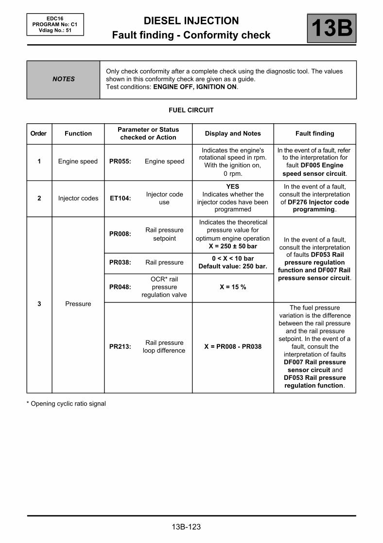
DIESEL INJECTIONFault finding - Conformity check 13B
13B-123
EDC16PROGRAM No: C1
Vdiag No.: 51
FUEL CIRCUIT
* Opening cyclic ratio signal
NOTESOnly check conformity after a complete check using the diagnostic tool. The values shown in this conformity check are given as a guide.Test conditions: ENGINE OFF, IGNITION ON.
Order FunctionParameter or Statuschecked or Action
Display and Notes Fault finding
1 Engine speed PR055: Engine speed
Indicates the engine's rotational speed in rpm.
With the ignition on, 0 rpm.
In the event of a fault, refer to the interpretation for
fault DF005 Engine speed sensor circuit.
2 Injector codes ET104:Injector code
use
YESIndicates whether the
injector codes have been programmed
In the event of a fault, consult the interpretation of DF276 Injector code
programming.
3 Pressure
PR008:Rail pressure
setpoint
Indicates the theoretical pressure value for
optimum engine operationX = 250 ±±±± 50 bar
In the event of a fault, consult the interpretation
of faults DF053 Rail pressure regulation
function and DF007 Rail pressure sensor circuit.
PR038: Rail pressure0 < X < 10 bar
Default value: 250 bar.
PR048:OCR* rail pressure
regulation valveX = 15 %
PR213:Rail pressure
loop differenceX = PR008 - PR038
The fuel pressure variation is the difference between the rail pressure
and the rail pressure setpoint. In the event of a
fault, consult the interpretation of faults DF007 Rail pressure
sensor circuit and DF053 Rail pressure regulation function.
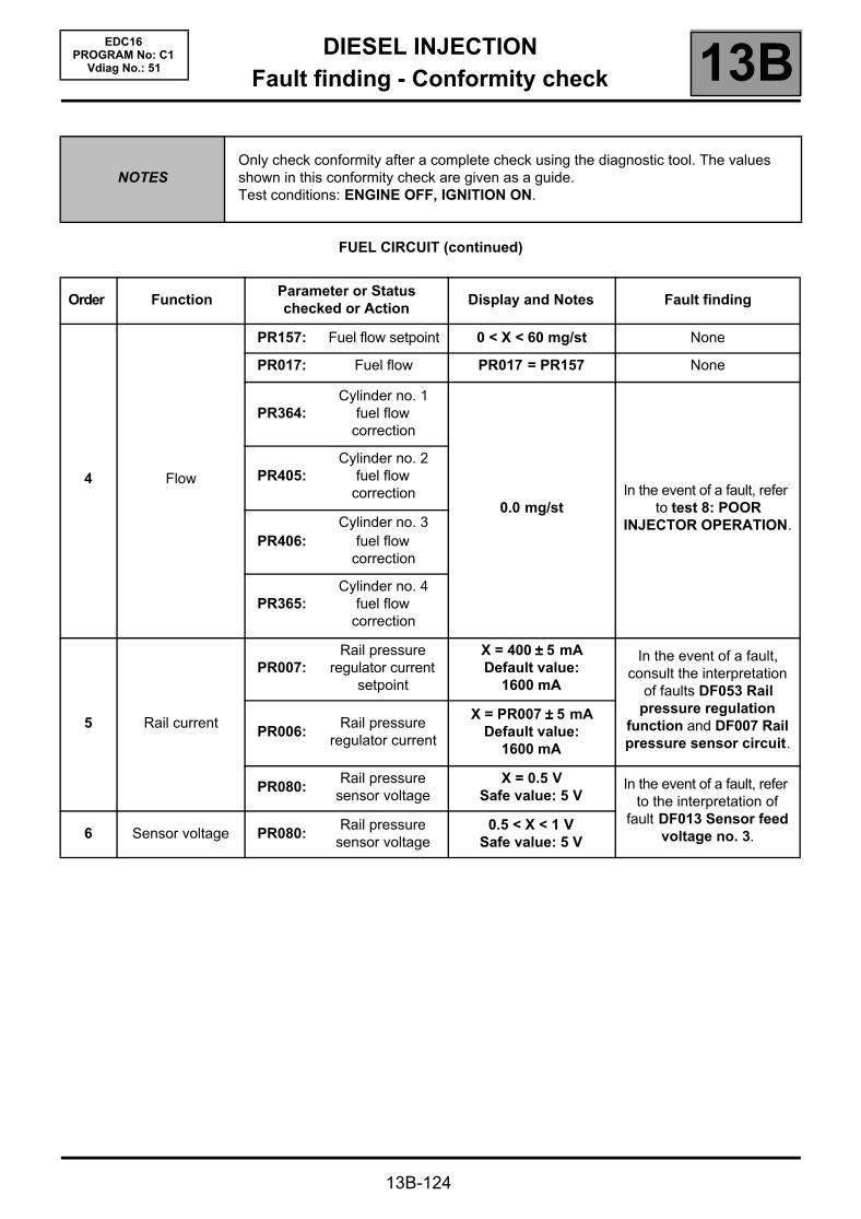
DIESEL INJECTIONFault finding - Conformity check 13B
13B-124
EDC16PROGRAM No: C1
Vdiag No.: 51
FUEL CIRCUIT (continued)
NOTESOnly check conformity after a complete check using the diagnostic tool. The values shown in this conformity check are given as a guide.Test conditions: ENGINE OFF, IGNITION ON.
Order FunctionParameter or Statuschecked or Action
Display and Notes Fault finding
4 Flow
PR157: Fuel flow setpoint 0 < X < 60 mg/st None
PR017: Fuel flow PR017 = PR157 None
PR364:Cylinder no. 1
fuel flow correction
0.0 mg/stIn the event of a fault, refer
to test 8: POOR INJECTOR OPERATION.
PR405:Cylinder no. 2
fuel flow correction
PR406:Cylinder no. 3
fuel flow correction
PR365:Cylinder no. 4
fuel flow correction
5 Rail current
PR007:Rail pressure
regulator current setpoint
X = 400 ±±±± 5 mADefault value:
1600 mA
In the event of a fault, consult the interpretation
of faults DF053 Rail pressure regulation
function and DF007 Rail pressure sensor circuit.
PR006:Rail pressure
regulator current
X = PR007 ±±±± 5 mADefault value:
1600 mA
PR080:Rail pressure
sensor voltageX = 0.5 V
Safe value: 5 VIn the event of a fault, refer
to the interpretation of fault DF013 Sensor feed
voltage no. 3.6 Sensor voltage PR080:Rail pressure
sensor voltage0.5 < X < 1 V
Safe value: 5 V

DIESEL INJECTIONFault finding - Conformity check 13B
13B-125
EDC16PROGRAM No: C1
Vdiag No.: 51
EMISSION CONTROL/OBD
NOTESOnly check conformity after a complete check using the diagnostic tool. The values shown in this conformity check are given as a guide.Test conditions: ENGINE OFF, IGNITION ON.
Order FunctionParameter or Statuschecked or Action
Display and Notes Fault finding
1 Engine speed PR055: Engine speedGives the engine's
speed in rpm
In the event of a fault, refer to the interpretation for fault
DF005 Engine speed sensor circuit.
2Exhaust gas recirculation
ET651:EGR
programming cut-off
NONEIn the event of a fault, refer to the interpretation of ET651
EGR programming cut-off.
PR005:EGR valve
opening setpoint
Gives a theoretical EGR valve opening value for optimum engine operation.
- 10 < X < 0 %
In the event of a fault, refer to fault interpretation DF272
EGR control circuit.
PR051:EGR valve
position feedback
- 10 < X < 0 %In the event of a fault, consult the interpretation of DF118
EGR solenoid valve control
The EGR valve position feedback loop difference must equal the difference between the EGR valve position and the position
feedback.
PR022:
EGR valve position
feedback loop difference
X = PR005 - PR051
PR128:First EGR valve
offset10 % < X < 40 %(average value)
In the event of a fault, apply command SC036
Reinitialisation of programming and EGR
valve.PR129:
Last EGR valve offset
10 % < X < 40 %(average value)

DIESEL INJECTIONFault finding - Conformity check 13B
13B-126
EDC16PROGRAM No: C1
Vdiag No.: 51
EMISSION CONTROL/OBD (CONTINUED)
NOTESOnly check conformity after a complete check using the diagnostic tool. The values shown in this conformity check are given as a guide.Test conditions: ENGINE OFF, IGNITION ON.
Order FunctionParameter or Statuschecked or Action
Display and Notes Fault finding
3 Air regulation
PR171:Air flow setpoint
for the EGR 750 ±±±± 200 mg/st
In the event of a fault, consult the interpretation of parameter DF056 Air flow
sensor circuit.
PR132: Air flow 0 < X < 10 kg/h
PR146: Inlet air flow
Indicates the air flow entering the engine
in mg/st0 mg/st
PR131:EGR air flow
variation
X = PR146 - PR171should be close to 0 with ignition on
4 Sensor feed PR077:EGR valve
position sensor voltage
0.5 < X < 1.5 Vdefault value: 0 V
In the event of a fault, refer to the interpretation of fault
DF012 Sensor supply voltage no. 2.
5 Temperature PR064:Coolant
temperature
Shows the engine coolant temperature
in °CDefault value: 119 °°°°C
In the event of a fault, refer to the interpretation of
DF001 Coolant temperature sensor
circuit.
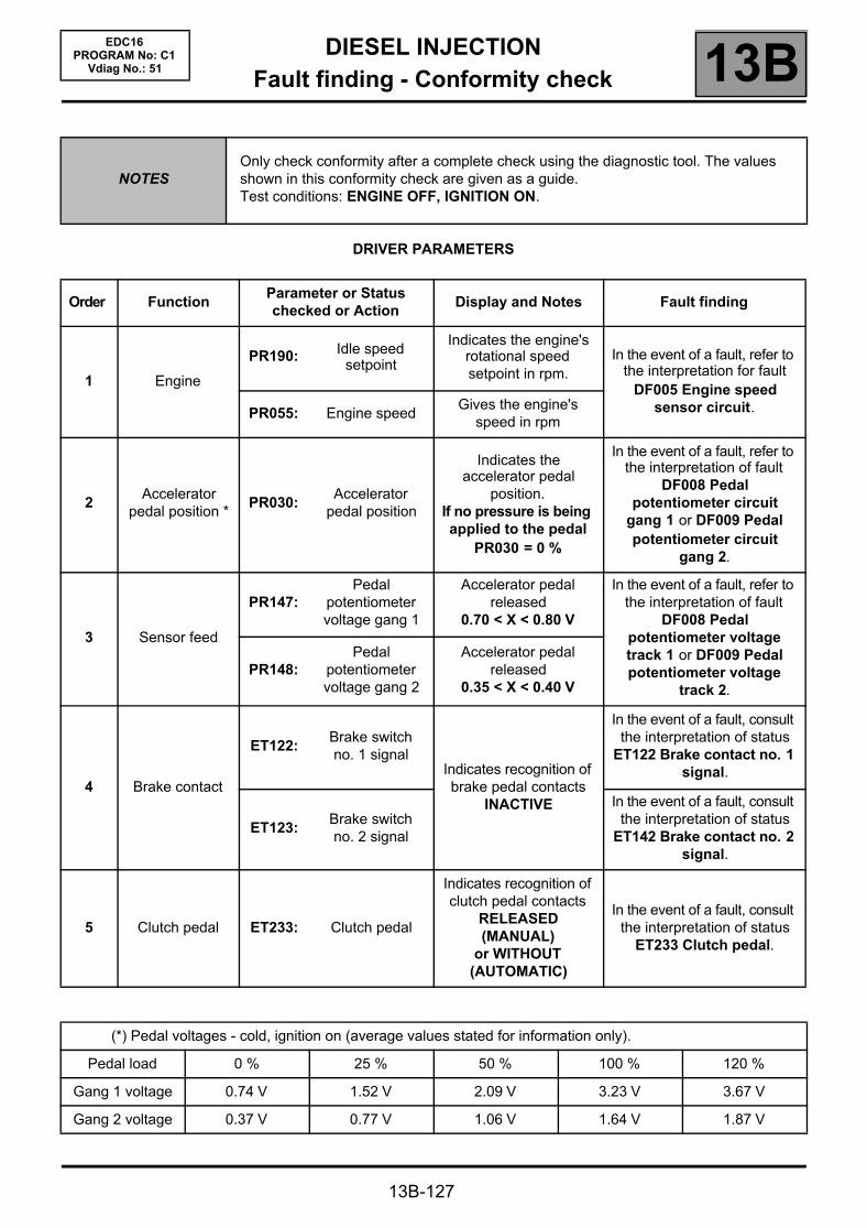
DIESEL INJECTIONFault finding - Conformity check 13B
13B-127
EDC16PROGRAM No: C1
Vdiag No.: 51
DRIVER PARAMETERS
NOTESOnly check conformity after a complete check using the diagnostic tool. The values shown in this conformity check are given as a guide.Test conditions: ENGINE OFF, IGNITION ON.
Order FunctionParameter or Statuschecked or Action
Display and Notes Fault finding
1 Engine
PR190: Idle speed setpoint
Indicates the engine's rotational speed setpoint in rpm.
In the event of a fault, refer to the interpretation for fault
DF005 Engine speed sensor circuit.PR055: Engine speed
Gives the engine's speed in rpm
2Accelerator
pedal position *PR030:
Accelerator pedal position
Indicates the accelerator pedal
position.If no pressure is being applied to the pedal
PR030 = 0 %
In the event of a fault, refer to the interpretation of fault
DF008 Pedal potentiometer circuit
gang 1 or DF009 Pedal potentiometer circuit
gang 2.
3 Sensor feed
PR147:Pedal
potentiometer voltage gang 1
Accelerator pedal released
0.70 < X < 0.80 V
In the event of a fault, refer to the interpretation of fault
DF008 Pedal potentiometer voltage track 1 or DF009 Pedal potentiometer voltage
track 2.PR148:
Pedal potentiometer voltage gang 2
Accelerator pedal released
0.35 < X < 0.40 V
4 Brake contact
ET122:Brake switch no. 1 signal
Indicates recognition of brake pedal contacts
INACTIVE
In the event of a fault, consult the interpretation of status
ET122 Brake contact no. 1 signal.
ET123:Brake switch no. 2 signal
In the event of a fault, consult the interpretation of status
ET142 Brake contact no. 2 signal.
5 Clutch pedal ET233: Clutch pedal
Indicates recognition of clutch pedal contacts
RELEASED (MANUAL)
or WITHOUT (AUTOMATIC)
In the event of a fault, consult the interpretation of status
ET233 Clutch pedal.
(*) Pedal voltages - cold, ignition on (average values stated for information only).
Pedal load 0 % 25 % 50 % 100 % 120 %
Gang 1 voltage 0.74 V 1.52 V 2.09 V 3.23 V 3.67 V
Gang 2 voltage 0.37 V 0.77 V 1.06 V 1.64 V 1.87 V

DIESEL INJECTIONFault finding - Conformity check 13B
13B-128
EDC16PROGRAM No: C1
Vdiag No.: 51
IGNITION/PREHEATING
NOTESOnly check conformity after a complete check using the diagnostic tool. The values shown in this conformity check are given as a guide.Test conditions: ENGINE OFF, IGNITION ON.
Order FunctionParameter or Statuschecked or Action
Display and Notes Fault finding
1 Supply ET001:Computer + after
ignition feedPRESENT
In the event of a fault, perform fault finding for
DF047 Computer supply voltage.
2 Engine
ET038: Engine STOPPED None
PR055: Engine speedGives the engine's
speed in rpm
In the event of a fault, refer to the interpretation for
fault DF005 Engine speed sensor circuit.
3 Temperature
PR064: Coolant temperature
Shows the engine coolant temperature
in °CDefault value: 119 °°°°C
In the event of a fault, refer to the interpretation of
DF001 Coolant temperature sensor
circuit.
PR059:Inlet air
temperature
Indicates the inlet air temperature in °C
Default value: 20 °°°°C
In the event of a fault, refer to the interpretation of fault DF039 Inlet air temperature sensor
circuit
4 Preheating ET007:Preheating unit
control
Status ET007 is ACTIVE a few
seconds after the ignition is switched
on and for the postheating
In the event of a fault (ET007 locked on
ACTIVE), consult the interpretation of fault
DF017 Preheating unit control circuit.
5 Supply PR071:Computer feed
voltage9 V < voltage < 16 V
In the event of a fault, consult the interpretation of fault DF047 computer
supply voltage.

DIESEL INJECTIONFault finding - Conformity check 13B
13B-129
EDC16PROGRAM No: C1
Vdiag No.: 51
ENGINE COOLING
NOTESOnly check conformity after a complete check using the diagnostic tool. The values shown in this conformity check are given as a guide.Test conditions: ENGINE OFF, IGNITION ON.
Order FunctionParameter or Statuschecked or Action
Display and Notes Fault finding
1Coolant
temperaturePR064:
Coolant temperature
Shows the engine coolant temperature
in °CDefault value: 119 °°°°C
In the event of a fault, refer to the interpretation of
DF001 Coolant temperature sensor
circuit.
2 Fan assemblies
ET021:Low speed GMV
requestWith the ignition
switched on, engine < 80° INACTIVE
If the fan assemblies are supplied with the ignition
on, the injection may be in defect mode.
Carry out a system fault test and refer to the
interpretation of faults.
ET022:High speed GMV
request
ET014:Monitor cooling
fan 1With the ignition
switched on, engine < 80° STOPPEDET015:
Monitor cooling fan 2
3 Sensor feed PR084:Coolant
temperature sensor voltage
3 < X < 4 VSafe value: 5 V
In the event of a fault, refer to the interpretation of
DF001 Coolant temperature sensor
circuit.
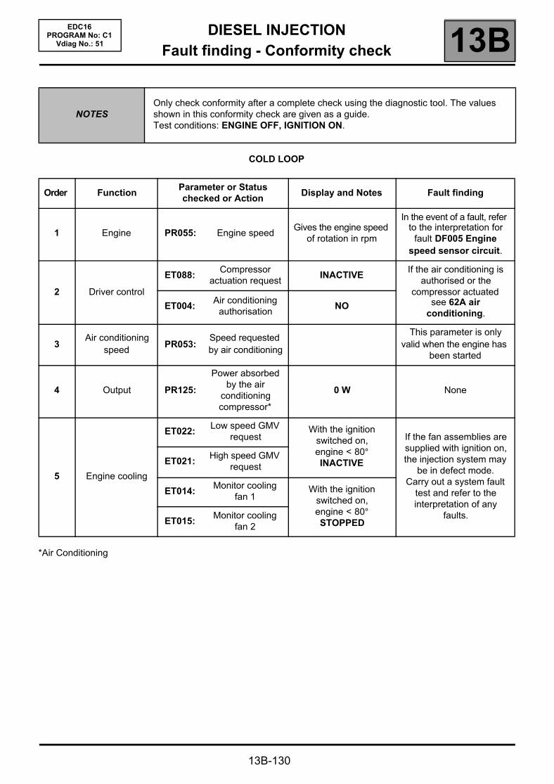
DIESEL INJECTIONFault finding - Conformity check 13B
13B-130
EDC16PROGRAM No: C1
Vdiag No.: 51
COLD LOOP
*Air Conditioning
NOTESOnly check conformity after a complete check using the diagnostic tool. The values shown in this conformity check are given as a guide.Test conditions: ENGINE OFF, IGNITION ON.
Order FunctionParameter or Statuschecked or Action
Display and Notes Fault finding
1 Engine PR055: Engine speedGives the engine speed
of rotation in rpm
In the event of a fault, refer to the interpretation for
fault DF005 Engine speed sensor circuit.
2 Driver control
ET088:Compressor
actuation requestINACTIVE
If the air conditioning is authorised or the
compressor actuated see 62A air
conditioning.ET004:
Air conditioning authorisation
NO
3Air conditioning
speedPR053:
Speed requested by air conditioning
This parameter is only valid when the engine has
been started
4 Output PR125:
Power absorbed by the air
conditioning compressor*
0 W None
5 Engine cooling
ET022:Low speed GMV
requestWith the ignition
switched on, engine < 80° INACTIVE
If the fan assemblies are supplied with ignition on, the injection system may
be in defect mode.Carry out a system fault
test and refer to the interpretation of any
faults.
ET021:High speed GMV
request
ET014:Monitor cooling
fan 1With the ignition
switched on, engine < 80° STOPPEDET015:
Monitor cooling fan 2

DIESEL INJECTIONFault finding - Conformity check 13B
13B-131
EDC16PROGRAM No: C1
Vdiag No.: 51
COLD LOOP (CONTINUED)
NOTESOnly check conformity after a complete check using the diagnostic tool. The values shown in this conformity check are given as a guide.Test conditions: ENGINE OFF, IGNITION ON.
Order FunctionParameter or Statuschecked or Action
Display and Notes Fault finding
6Coolant
temperaturePR064:
Coolant temperature
Shows the engine coolant temperature in °C
Default value: 119 °C
In the event of a fault, refer to the interpretation of
DF001 Coolant temperature sensor
circuit.
7 Vehicle speed PR089: Vehicle speed
Gives the vehicle speed in mph. This parameter is transmitted by the ABS computer. This signal is
transmitted to the injection on the multiplex
network.
In the event of a fault, test the multiplex network.
For the interpretation of possible faults (see 38C,
Anti-lock braking system).
8 Pressure PR037:Refrigerant pressure
2 bar < PR037 < 27 barIn the event of a fault, refer
to the fault finding procedure for fault DF049
Refrigerant sensor circuit.
9 Voltage PR076:Refrigerant
sensor voltage0 V < X < 5 V

DIESEL INJECTIONFault finding - Conformity check 13B
13B-132
EDC16PROGRAM No: C1
Vdiag No.: 51
HEATING
NOTESOnly check conformity after a complete check using the diagnostic tool. The values shown in this conformity check are given as a guide.Test conditions: ENGINE OFF, IGNITION ON.
Order FunctionParameter or Statuschecked or Action
Display and Notes Fault finding
1Coolant
temperaturePR064:
Coolant temperature
Shows the engine coolant temperature in °C
Default value: 119 °°°°C
In the event of a fault, refer to the interpretation of
DF001 Coolant temperature sensor
circuit.
2
Passenger Compartment
Heating Resistors (RCH)
ET111:
Set number of Passenger
Compartment Heating
Resistors
Depending on the requirements of the
injection system (e.g. torque reduction,
power requirements), the injection computer sets the number of activated passenger compartment
heating resistors (no more or no fewer than
required)
If there is a fault, (see 87B, Passenger
compartment connection unit).
ET112:
Passenger Compartment
Heating Resistor cut-off
Status ET112 shows whether the injection
computer has requested the passenger
compartment heating resistors to be cut out
ET112 = YES
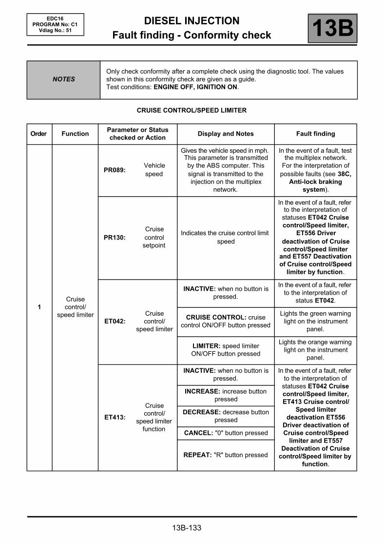
DIESEL INJECTIONFault finding - Conformity check 13B
13B-133
EDC16PROGRAM No: C1
Vdiag No.: 51
CRUISE CONTROL/SPEED LIMITER
NOTESOnly check conformity after a complete check using the diagnostic tool. The values shown in this conformity check are given as a guide.Test conditions: ENGINE OFF, IGNITION ON.
Order FunctionParameter or Statuschecked or Action
Display and Notes Fault finding
1Cruise control/
speed limiter
PR089:Vehicle speed
Gives the vehicle speed in mph. This parameter is transmitted by the ABS computer. This signal is transmitted to the injection on the multiplex
network.
In the event of a fault, test the multiplex network.
For the interpretation of possible faults (see 38C,
Anti-lock braking system).
PR130:Cruise control
setpoint
Indicates the cruise control limit speed
In the event of a fault, refer to the interpretation of
statuses ET042 Cruise control/Speed limiter,
ET556 Driver deactivation of Cruise control/Speed limiter
and ET557 Deactivation of Cruise control/Speed
limiter by function.
ET042:Cruise control/
speed limiter
INACTIVE: when no button is pressed.
In the event of a fault, refer to the interpretation of
status ET042.
CRUISE CONTROL: cruise control ON/OFF button pressed
Lights the green warning light on the instrument
panel.
LIMITER: speed limiter ON/OFF button pressed
Lights the orange warning light on the instrument
panel.
ET413:
Cruise control/
speed limiter function
INACTIVE: when no button is pressed.
In the event of a fault, refer to the interpretation of
statuses ET042 Cruise control/Speed limiter, ET413 Cruise control/
Speed limiter deactivation ET556
Driver deactivation of Cruise control/Speed
limiter and ET557 Deactivation of Cruise
control/Speed limiter by function.
INCREASE: increase button pressed
DECREASE: decrease button pressed
CANCEL: "0" button pressed
REPEAT: "R" button pressed
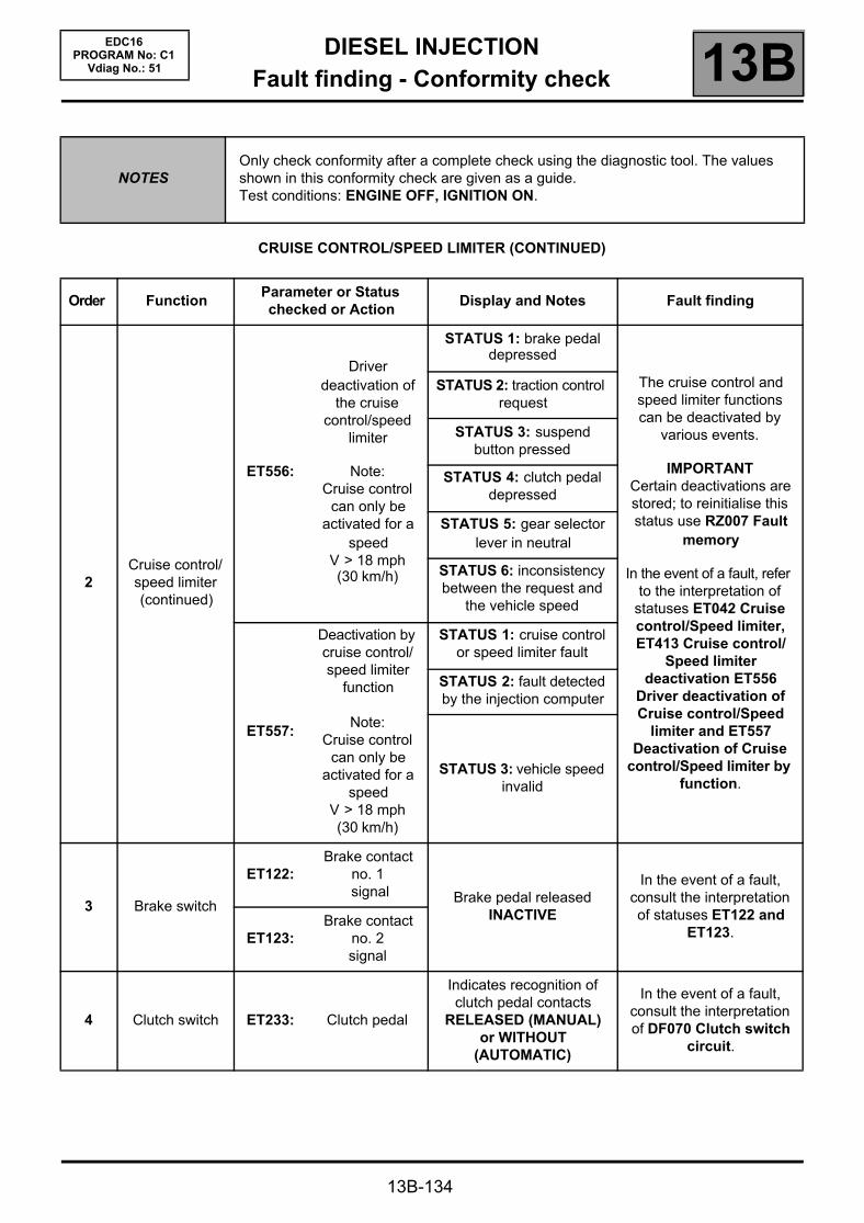
DIESEL INJECTIONFault finding - Conformity check 13B
13B-134
EDC16PROGRAM No: C1
Vdiag No.: 51
CRUISE CONTROL/SPEED LIMITER (CONTINUED)
NOTESOnly check conformity after a complete check using the diagnostic tool. The values shown in this conformity check are given as a guide.Test conditions: ENGINE OFF, IGNITION ON.
Order FunctionParameter or Statuschecked or Action
Display and Notes Fault finding
2Cruise control/speed limiter (continued)
ET556:
Driver deactivation of
the cruise control/speed
limiter
Note:Cruise control
can only be activated for a
speedV > 18 mph (30 km/h)
STATUS 1: brake pedal depressed
The cruise control and speed limiter functions can be deactivated by
various events.
IMPORTANTCertain deactivations are stored; to reinitialise this status use RZ007 Fault
memory
In the event of a fault, refer to the interpretation of
statuses ET042 Cruise control/Speed limiter, ET413 Cruise control/
Speed limiter deactivation ET556
Driver deactivation of Cruise control/Speed
limiter and ET557 Deactivation of Cruise
control/Speed limiter by function.
STATUS 2: traction control request
STATUS 3: suspend button pressed
STATUS 4: clutch pedal depressed
STATUS 5: gear selector lever in neutral
STATUS 6: inconsistency between the request and
the vehicle speed
ET557:
Deactivation by cruise control/speed limiter
function
Note:Cruise control
can only be activated for a
speedV > 18 mph (30 km/h)
STATUS 1: cruise control or speed limiter fault
STATUS 2: fault detected by the injection computer
STATUS 3: vehicle speed invalid
3 Brake switch
ET122:Brake contact
no. 1 signal Brake pedal released
INACTIVE
In the event of a fault, consult the interpretation of statuses ET122 and
ET123.ET123:Brake contact
no. 2signal
4 Clutch switch ET233: Clutch pedal
Indicates recognition of clutch pedal contacts
RELEASED (MANUAL)or WITHOUT
(AUTOMATIC)
In the event of a fault, consult the interpretation of DF070 Clutch switch
circuit.

DIESEL INJECTIONFault finding - Conformity check 13B
13B-135
EDC16PROGRAM No: C1
Vdiag No.: 51
STARTING
NOTESOnly check conformity after a complete check using the diagnostic tool. The values shown in this conformity check are given as a guide.Test conditions: ENGINE OFF, IGNITION ON.
Order FunctionParameter or Statuschecked or Action
Display and Notes Fault finding
1 Supply ET001:Computer + after
ignition feedPRESENT
In the event of a fault, carry out a full fault finding procedure on the charging
circuit.
2 Starting
ET238: Synchronisation NOT DONE
In the event of a fault, refer to fault interpretation
DF195 Camshaft/engine speed sensor consistency.
ET076: StartingAUTHORISED:
the injection authorises starting
If status ET076 is PROHIBITED, carry out a
complete fault finding procedure on the multiplex network.
3Engine
operation.ET038: Engine STOPPED None
4 Supply
PR071:Computer feed
voltage9 V < voltage < 16 V
In the event of a fault, consult the interpretation of fault DF047 Computer
supply voltage.
PR358:Sensor reference
voltage3.4 V < voltage < 3.8 V None
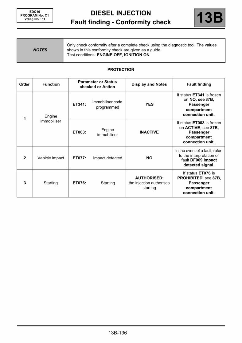
DIESEL INJECTIONFault finding - Conformity check 13B
13B-136
EDC16PROGRAM No: C1
Vdiag No.: 51
PROTECTION
NOTESOnly check conformity after a complete check using the diagnostic tool. The values shown in this conformity check are given as a guide.Test conditions: ENGINE OFF, IGNITION ON.
Order FunctionParameter or Statuschecked or Action
Display and Notes Fault finding
1Engine
immobiliser
ET341:Immobiliser code
programmedYES
If status ET341 is frozen on NO, see 87B,
Passenger compartment
connection unit.
ET003:Engine
immobiliserINACTIVE
If status ET003 is frozen on ACTIVE, see 87B,
Passenger compartment
connection unit.
2 Vehicle impact ET077: Impact detected NO
In the event of a fault, refer to the interpretation of
fault DF069 Impact detected signal.
3 Starting ET076: StartingAUTHORISED:
the injection authorises starting
If status ET076 is PROHIBITED, see 87B,
Passenger compartment
connection unit.

DIESEL INJECTIONFault finding - Conformity check 13B
13B-137
EDC16PROGRAM No: C1
Vdiag No.: 51
MAIN COMPUTER STATUSES AND PARAMETERS
NOTESOnly check conformity after a complete check using the diagnostic tool. The values shown in this conformity check are given as a guide.Test Conditions: ENGINE AT IDLE SPEED, COOLANT TEMPERATURE > 80 °°°°C.
Order FunctionParameter or Statuschecked or Action
Display and Notes Fault finding
1 Vehicle impact ET077:Impact
detectedNO
In the event of a fault, refer to the interpretation of fault DF069 Impact detected
signal.
2 Supply
ET001:Computer
+ after ignition feed
PRESENTIn the event of a fault, refer to
the interpretation of DF015 Main relay control circuit.
PR071:Computer feed
voltage9 V < X < 16 V
In the event of a fault, carry out a fault finding procedure
on the charge circuit and refer to the interpretation for DF047 Computer supply voltage.
PR358:Sensor
reference voltage
3.4 V < X < 3.8 V None
3 Engine running PR055: Engine speedGives the engine's rotational speed in
rpm.
In the event of a fault, refer to the interpretation for fault
DF005 Engine speed sensor circuit.
4Injection
configurationET104:
Injector code use
YES
This status indicates that the IMA function is activated. In
the event of a fault, consult the interpretation of DF276
Injector code programming.
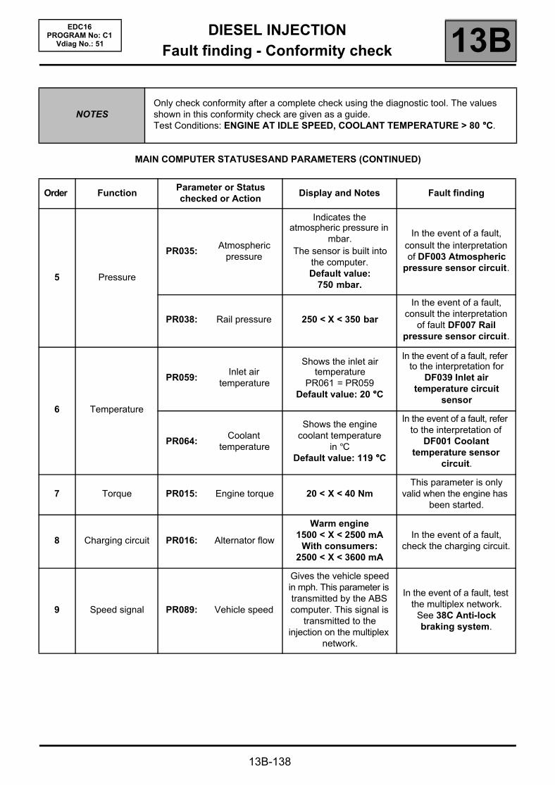
DIESEL INJECTIONFault finding - Conformity check 13B
13B-138
EDC16PROGRAM No: C1
Vdiag No.: 51
MAIN COMPUTER STATUSES AND PARAMETERS (CONTINUED)
NOTESOnly check conformity after a complete check using the diagnostic tool. The values shown in this conformity check are given as a guide.Test Conditions: ENGINE AT IDLE SPEED, COOLANT TEMPERATURE > 80 °°°°C.
Order FunctionParameter or Statuschecked or Action
Display and Notes Fault finding
5 Pressure
PR035:Atmospheric
pressure
Indicates the atmospheric pressure in
mbar.The sensor is built into
the computer.Default value:
750 mbar.
In the event of a fault, consult the interpretation of DF003 Atmospheric
pressure sensor circuit.
PR038: Rail pressure 250 < X < 350 bar
In the event of a fault, consult the interpretation
of fault DF007 Rail pressure sensor circuit.
6 Temperature
PR059:Inlet air
temperature
Shows the inlet air temperature
PR061 = PR059Default value: 20 °°°°C
In the event of a fault, refer to the interpretation for
DF039 Inlet air temperature circuit
sensor
PR064:Coolant
temperature
Shows the engine coolant temperature
in °CDefault value: 119 °°°°C
In the event of a fault, refer to the interpretation of
DF001 Coolant temperature sensor
circuit.
7 Torque PR015: Engine torque 20 < X < 40 NmThis parameter is only
valid when the engine has been started.
8 Charging circuit PR016: Alternator flow
Warm engine1500 < X < 2500 mA
With consumers:2500 < X < 3600 mA
In the event of a fault, check the charging circuit.
9 Speed signal PR089: Vehicle speed
Gives the vehicle speed in mph. This parameter is transmitted by the ABS computer. This signal is
transmitted to the injection on the multiplex
network.
In the event of a fault, test the multiplex network.
See 38C Anti-lock braking system.
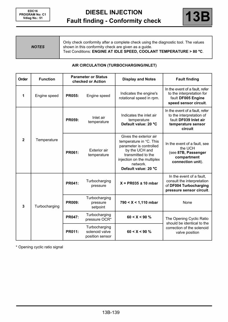
DIESEL INJECTIONFault finding - Conformity check 13B
13B-139
EDC16PROGRAM No: C1
Vdiag No.: 51
AIR CIRCULATION (TURBOCHARGING/INLET)
* Opening cyclic ratio signal
NOTESOnly check conformity after a complete check using the diagnostic tool. The values shown in this conformity check are given as a guide.Test Conditions: ENGINE AT IDLE SPEED, COOLANT TEMPERATURE > 80 °°°°C.
Order FunctionParameter or Statuschecked or Action
Display and Notes Fault finding
1 Engine speed PR055: Engine speedIndicates the engine's
rotational speed in rpm.
In the event of a fault, refer to the interpretation for
fault DF005 Engine speed sensor circuit.
2 Temperature
PR059:Inlet air
temperature
Indicates the inlet air temperature
Default value: 20 °°°°C
In the event of a fault, refer to the interpretation of fault DF039 Inlet air temperature sensor
circuit
PR061:Exterior air
temperature
Gives the exterior air temperature in °C. This parameter is controlled
by the UCH and transmitted to the
injection on the multiplex network.
Default value: 20 °°°°C
In the event of a fault, see the UCH
(see 87B, Passenger compartment
connection unit).
3 Turbocharging
PR041:Turbocharging
pressureX = PR035 ±±±± 10 mbar
In the event of a fault, consult the interpretation of DF004 Turbocharging pressure sensor circuit.
PR009:Turbocharging
pressure setpoint
790 < X < 1,110 mbar None
PR047:Turbocharging pressure OCR*
60 < X < 90 % The Opening Cyclic Ratio should be identical to the correction of the solenoid
valve positionPR011:Turbocharging solenoid valve position sensor
60 < X < 90 %

DIESEL INJECTIONFault finding - Conformity check 13B
13B-140
EDC16PROGRAM No: C1
Vdiag No.: 51
AIR CIRCULATION (TURBOCHARGING/INLET) (CONTINUED)
* Opening cyclic ratio signal
NOTESOnly check conformity after a complete check using the diagnostic tool. The values shown in this conformity check are given as a guide.Test Conditions: ENGINE AT IDLE SPEED, COOLANT TEMPERATURE > 80 °°°°C.
Order FunctionParameter or Statuschecked or Action
Display and Notes Fault finding
4 Air circulation
PR035:Atmospheric
pressure
Indicates the atmospheric pressure in mbar. The sensor is
integrated into the computer.
Default value: 750 mbar.
In the event of a fault, consult the interpretation of DF003 Atmospheric
pressure sensor circuit.
PR132: Air flow 25 < X < 50 kg/h
In the event of a fault, consult the interpretation of parameter DF056 Air
flow sensor circuit.
PR672:Damper valve
position setpoint X < 5 %In the event of a fault,
consult the interpretation for fault DF226 Damper
valve circuit.
PR417: OCR inlet air flap X < 5 %
PR420:Damper valve error counter
X = 0
5 Sensor feed
PR081:Inlet temperature sensor voltage
1.90 < X < 2.90 VSafe value: 5 V
In the event of a fault, refer to the interpretation of fault DF039 Inlet air temperature sensor
circuit.
PR079:Atmospheric
pressure sensor voltage
3.80 < X < 4 V
In the event of a fault, consult the interpretation of DF003 Atmospheric
pressure sensor circuit.
PR073:Air flow sensor
feed voltage1.5 < X < 2.5 VSafe value: 0 V
In the event of a fault, refer to the interpretation of
fault DF013 Sensor feed voltage no. 3

DIESEL INJECTIONFault finding - Conformity check 13B
13B-141
EDC16PROGRAM No: C1
Vdiag No.: 51
FUEL CIRCUIT
* Opening cyclic ratio signal
NOTESOnly check conformity after a complete check using the diagnostic tool. The values shown in this conformity check are given as a guide.Test Conditions: ENGINE AT IDLE SPEED, COOLANT TEMPERATURE > 80 °°°°C.
Order FunctionParameter or Statuschecked or Action
Display and Notes Fault finding
1 Engine speed PR055: Engine speedIndicates the engine's
rotational speed in rpm.
In the event of a fault, refer to the interpretation for
fault DF005 Engine speed sensor circuit.
2 Injector codes ET104:Injector code
operation
YESIndicates whether the
injector codes have been programmed
In the event of a fault, consult the interpretation of DF276 Injector code
programming.
3 Pressure
PR008:Rail pressure
setpoint
Indicates the theoretical pressure value for optimum engine
operationX = 270 ±±±± 50 bar
In the event of a fault, refer to the interpretation of
fault DF053 Rail pressure regulator
function.
PR038: Rail pressureX = ~ 315 bar
Default value: 250 bar. In the event of a fault, consult the interpretation
of fault DF007 Rail pressure sensor circuit.PR048:
OCR* rail pressure
regulation valve35 < X < 45 %
PR213:Rail pressure
loop differenceX = PR008 - PR038
The fuel pressure variation is the difference between the rail pressure
and the rail pressure setpoint. In the event of a
fault, consult the interpretation of fault
DF007 Rail pressure sensor circuit.

DIESEL INJECTIONFault finding - Conformity check 13B
13B-142
EDC16PROGRAM No: C1
Vdiag No.: 51
FUEL CIRCUIT (continued)
NOTESOnly check conformity after a complete check using the diagnostic tool. The values shown in this conformity check are given as a guide.Test Conditions: ENGINE AT IDLE SPEED, COOLANT TEMPERATURE > 80 °°°°C.
Order FunctionParameter or Statuschecked or Action
Display and Notes Fault finding
4 Flow
PR017: Fuel flow X = 0 < X < 60 mg/st None
PR157: Fuel flow setpoint PR017 = PR157 None
PR364:Cylinder no. 1
fuel flow correction
±±±± 1 mg/st
In the event of a fault, refer to the interpretation of
test 8: POOR INJECTOR OPERATION.
PR405:Cylinder no. 2
fuel flow correction
PR406:Cylinder no. 3
fuel flow correction
PR365:Cylinder no. 4
fuel flow correction
5 Rail current
PR007:Rail pressure
regulator current setpoint
X = 1400 ±±±± 50 mADefault value:
1600 mAIn the event of a fault,
consult the interpretation of fault DF007 Rail
pressure sensor circuit.PR006:Rail pressure
regulator current
X = PR007 ±±±± 5 mADefault value:
1600 mA
PR080:Rail pressure
sensor voltage1 < X < 1.5 V
Safe value: 5 V
In the event of a fault, refer to the interpretation of
fault DF013 Sensor feed voltage no. 3

DIESEL INJECTIONFault finding - Conformity check 13B
13B-143
EDC16PROGRAM No: C1
Vdiag No.: 51
EMISSION CONTROL/OBD
NOTESOnly check conformity after a complete check using the diagnostic tool. The values shown in this conformity check are given as a guide.Test Conditions: ENGINE AT IDLE SPEED, COOLANT TEMPERATURE > 80 °°°°C.
Order FunctionParameter or Statuschecked or Action
Display and Notes Fault finding
1 Engine speed PR055: Engine speedGives the engine's
speed in rpm
In the event of a fault, refer to the interpretation for fault
DF005 Engine speed sensor circuit.
2Exhaust gas recirculation
ET651:EGR
programming cut-off
NONE
In the event of a fault, refer to the interpretation of
ET651 EGR programming cut-off.
PR005:EGR valve
opening setpoint
Gives a theoretical EGR valve opening value for optimum engine operation.
10 < X < 40 %
In the event of a fault, refer to fault interpretation DF272 EGR control
circuit.
PR051:EGR valve
position feedback
10 < X < 40 %In the event of a fault, refer
to the interpretation of DF118 EGR solenoid
valve control.The EGR valve position feedback loop difference must equal the difference between the EGR valve position and the position
feedback.
PR022:
EGR valve position
feedback loop difference
X = PR005 - PR051must be close to 0 at
idle speed
PR128:First EGR valve
offset10 % < X < 40 %(average value)
In the event of a fault, apply command SC036 Reset programming and EGR
valve.PR129:Last EGR valve
offset10 % < X < 40 %(average value)
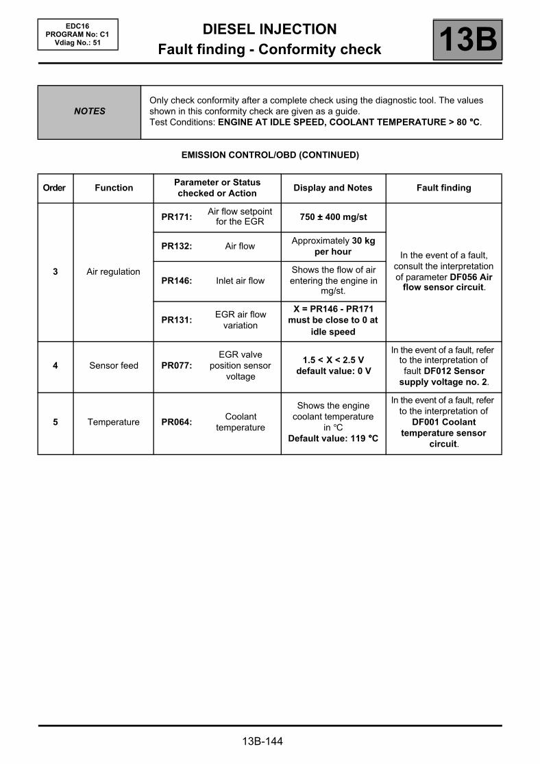
DIESEL INJECTIONFault finding - Conformity check 13B
13B-144
EDC16PROGRAM No: C1
Vdiag No.: 51
EMISSION CONTROL/OBD (CONTINUED)
NOTESOnly check conformity after a complete check using the diagnostic tool. The values shown in this conformity check are given as a guide.Test Conditions: ENGINE AT IDLE SPEED, COOLANT TEMPERATURE > 80 °°°°C.
Order FunctionParameter or Statuschecked or Action
Display and Notes Fault finding
3 Air regulation
PR171:Air flow setpoint
for the EGR 750 ±±±± 400 mg/st
In the event of a fault, consult the interpretation of parameter DF056 Air
flow sensor circuit.
PR132: Air flowApproximately 30 kg
per hour
PR146: Inlet air flowShows the flow of air entering the engine in
mg/st.
PR131:EGR air flow
variation
X = PR146 - PR171must be close to 0 at
idle speed
4 Sensor feed PR077:EGR valve
position sensor voltage
1.5 < X < 2.5 Vdefault value: 0 V
In the event of a fault, refer to the interpretation of fault DF012 Sensor
supply voltage no. 2.
5 Temperature PR064:Coolant
temperature
Shows the engine coolant temperature
in °CDefault value: 119 °°°°C
In the event of a fault, refer to the interpretation of
DF001 Coolant temperature sensor
circuit.

DIESEL INJECTIONFault finding - Conformity check 13B
13B-145
EDC16PROGRAM No: C1
Vdiag No.: 51
DRIVER PARAMETERS
NOTESOnly check conformity after a complete check using the diagnostic tool. The values shown in this conformity check are given as a guide.Test Conditions: ENGINE AT IDLE SPEED, COOLANT TEMPERATURE > 80 °°°°C.
Order FunctionParameter or Statuschecked or Action
Display and Notes Fault finding
1 Engine
PR055: Engine speedGives the engine speed of
rotation in rpm In the event of a fault, refer to the interpretation for fault
DF005 Engine speed sensor circuit.PR190:
Idle speed setpoint
Indicates the engine's rotational speed setpoint
in rpm.
2Accelerator
pedal position *PR030:
Accelerator pedal position
Indicates the accelerator pedal position.
If no pressure is being applied to the pedal
PR030 = 0 %
In the event of a fault, refer to the interpretation of fault
DF008 Pedal potentiometer circuit
gang 1 or DF009 Pedal potentiometer circuit
gang 2.
3 Sensor feed
PR147:
Pedal potentiometer
voltage gang 1
Accelerator pedal released
0.70 < PR147 < 0.80 V
In the event of a fault, refer to the interpretation of fault
DF008 Pedal potentiometer voltage gang 1 or DF009 Pedal potentiometer voltage
gang 2.PR148:
Pedal potentiometer
voltage gang 2
Accelerator pedal released
0.35 < PR088 < 0.40 V
4 Brake contact
ET122:Brake switch no. 1 signal
Indicates recognition of brake pedal contacts
INACTIVE
In the event of a fault, consult the interpretation of
status ET122 Brake contact no. 1 signal.
ET123:Brake switch no. 2 signal
In the event of a fault, consult the interpretation of
status ET142 Brake contact no. 2 signal.
5 Clutch pedal ET233: Clutch pedal
Indicates recognition of clutch pedal contacts
RELEASED (MANUAL)or WITHOUT
(AUTOMATIC)
In the event of a fault, consult the interpretation of status ET233 Clutch pedal.
(*) Pedal voltages - cold, ignition on (average values stated for information only).
Pedal load 0 % 25 % 50 % 100 % 120 %
Gang 1 voltage 0.74 V 1.52 V 2.09 V 3.23 V 3.67 V
Gang 2 voltage 0.37 V 0.77 V 1.06 V 1.64 V 1.87 V
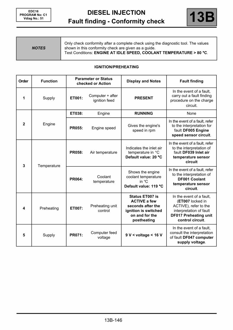
DIESEL INJECTIONFault finding - Conformity check 13B
13B-146
EDC16PROGRAM No: C1
Vdiag No.: 51
IGNITION/PREHEATING
NOTESOnly check conformity after a complete check using the diagnostic tool. The values shown in this conformity check are given as a guide.Test Conditions: ENGINE AT IDLE SPEED, COOLANT TEMPERATURE > 80 °°°°C.
Order FunctionParameter or Statuschecked or Action
Display and Notes Fault finding
1 Supply ET001:Computer + after
ignition feedPRESENT
In the event of a fault, carry out a fault finding
procedure on the charge circuit.
2 Engine
ET038: Engine RUNNING None
PR055: Engine speedGives the engine's
speed in rpm
In the event of a fault, refer to the interpretation for
fault DF005 Engine speed sensor circuit.
3 Temperature
PR058: Air temperatureIndicates the inlet air
temperature in °CDefault value: 20 °°°°C
In the event of a fault, refer to the interpretation of fault DF039 Inlet air temperature sensor
circuit
PR064:Coolant
temperature
Shows the engine coolant temperature
in °CDefault value: 119 °°°°C
In the event of a fault, refer to the interpretation of
DF001 Coolant temperature sensor
circuit.
4 Preheating ET007:Preheating unit
control
Status ET007 is ACTIVE a few
seconds after the ignition is switched
on and for the postheating
In the event of a fault, (ET007 locked in
ACTIVE), refer to the interpretation of fault
DF017 Preheating unit control circuit.
5 Supply PR071:Computer feed
voltage9 V < voltage < 16 V
In the event of a fault, consult the interpretation of fault DF047 computer
supply voltage.

DIESEL INJECTIONFault finding - Conformity check 13B
13B-147
EDC16PROGRAM No: C1
Vdiag No.: 51
ENGINE COOLING
NOTESOnly check conformity after a complete check using the diagnostic tool. The values shown in this conformity check are given as a guide.Test Conditions: ENGINE AT IDLE SPEED, COOLANT TEMPERATURE > 80 °°°°C.
Order FunctionParameter or Statuschecked or Action
Display and Notes Fault finding
1Coolant
temperaturePR064:
Coolant temperature
Shows the engine coolant temperature
in °CDefault value: 119 °°°°C
In the event of a fault, refer to the interpretation of
DF001 Coolant temperature sensor
circuit.
2 Fan assemblies
ET022:Low speed GMV
requestACTIVE if air
conditioning requestIf the fan assemblies are supplied with the ignition
on, the injection may be in defect mode.
Carry out a system fault test and refer to the
interpretation of faults.
ET021:High speed GMV
requestINACTIVE
ET014:Monitor cooling
fan 1
RUNNING if air conditioning
requested
ET015:Monitor cooling
fan 2STOPPED
3 Sensor feed PR084:Coolant
temperature sensor voltage
1 < X < 2 VSafe value: 5 V
In the event of a fault, refer to the interpretation of
DF001 Coolant temperature sensor
circuit.
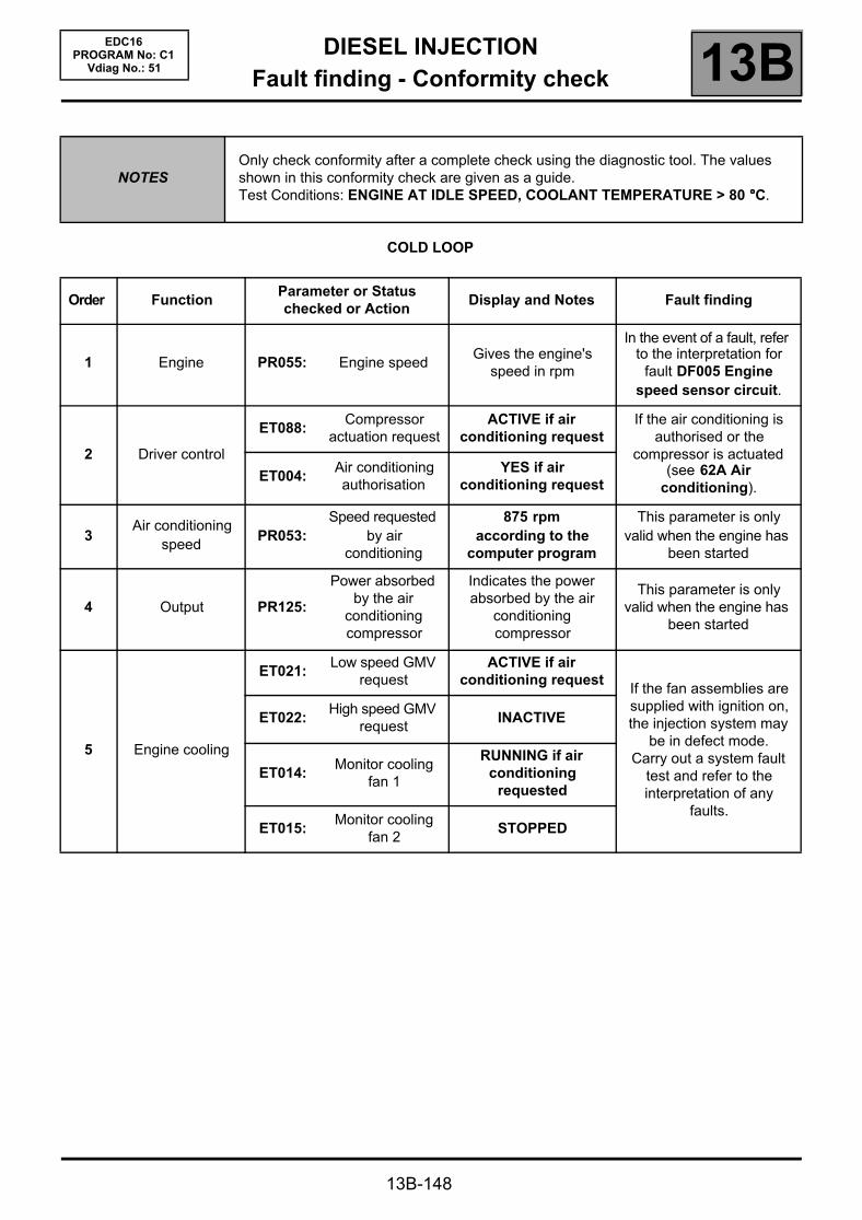
DIESEL INJECTIONFault finding - Conformity check 13B
13B-148
EDC16PROGRAM No: C1
Vdiag No.: 51
COLD LOOP
NOTESOnly check conformity after a complete check using the diagnostic tool. The values shown in this conformity check are given as a guide.Test Conditions: ENGINE AT IDLE SPEED, COOLANT TEMPERATURE > 80 °°°°C.
Order FunctionParameter or Statuschecked or Action
Display and Notes Fault finding
1 Engine PR055: Engine speedGives the engine's
speed in rpm
In the event of a fault, refer to the interpretation for
fault DF005 Engine speed sensor circuit.
2 Driver control
ET088:Compressor
actuation requestACTIVE if air
conditioning requestIf the air conditioning is
authorised or the compressor is actuated
(see 62A Air conditioning).
ET004:Air conditioning authorisation
YES if air conditioning request
3Air conditioning
speedPR053:
Speed requested by air
conditioning
875 rpmaccording to the
computer program
This parameter is only valid when the engine has
been started
4 Output PR125:
Power absorbed by the air
conditioning compressor
Indicates the power absorbed by the air
conditioning compressor
This parameter is only valid when the engine has
been started
5 Engine cooling
ET021:Low speed GMV
requestACTIVE if air
conditioning requestIf the fan assemblies are supplied with ignition on, the injection system may
be in defect mode.Carry out a system fault
test and refer to the interpretation of any
faults.
ET022:High speed GMV
requestINACTIVE
ET014:Monitor cooling
fan 1
RUNNING if air conditioning
requested
ET015:Monitor cooling
fan 2STOPPED

DIESEL INJECTIONFault finding - Conformity check 13B
13B-149
EDC16PROGRAM No: C1
Vdiag No.: 51
COLD LOOP (CONTINUED)
NOTESOnly check conformity after a complete check using the diagnostic tool. The values shown in this conformity check are given as a guide.Test Conditions: ENGINE AT IDLE SPEED, COOLANT TEMPERATURE > 80 °°°°C.
Order FunctionParameter or Statuschecked or Action
Display and Notes Fault finding
6Coolant
temperaturePR064:
Coolant temperature
Shows the engine coolant temperature
in °CDefault value: 119 °°°°C
In the event of a fault, refer to the interpretation of
DF001 Coolant temperature sensor
circuit.
7 Vehicle speed PR089: Vehicle speed
Gives the vehicle speed in mph. This
parameter is transmitted by the ABS computer. This signal is
transmitted to the injection on the
multiplex network.
In the event of a fault, test the multiplex network.
For the interpretation of possible faults (see 38C,
Anti-lock braking system).
8 Refrigerant
PR037:Refrigerant pressure
1 < X < 27 barIn the event of a fault, refer
to the fault finding procedure for fault DF049
Refrigerant sensor circuit.
PR076:Refrigerant
sensor voltage0 V < X < 5 V

DIESEL INJECTIONFault finding - Conformity check 13B
13B-150
EDC16PROGRAM No: C1
Vdiag No.: 51
HEATING
NOTESOnly check conformity after a complete check using the diagnostic tool. The values shown in this conformity check are given as a guide.Test Conditions: ENGINE AT IDLE SPEED, COOLANT TEMPERATURE > 80 °°°°C.
Order FunctionParameter or Statuschecked or Action
Display and Notes Fault finding
1Coolant
temperaturePR064:
Coolant temperature
Shows the engine coolant temperature in °C
Default value: 119 °°°°C
In the event of a fault, refer to the interpretation of
DF001 Coolant temperature sensor
circuit.
2
Passenger Compartment
Heating Resistors (RCH)
ET111:
Set number of Passenger
Compartment Heating
Resistors
Depending on the requirements of the
injection system (e.g. torque reduction, power
requirements), the injection computer sets the number of activated passenger compartment
heating resistors (no more or no fewer than
required)ET111 = NO
If there is a fault, (see 87B, Passenger
compartment connection unit).
ET112:
Passenger Compartment
Heating Resistor cut-off
Status ET112 shows whether the injection
computer has requested the passenger
compartment heating resistors to be cut out
ET112 = NO
DIESEL INJECTIONFault finding - Conformity check 13B
13B-151
EDC16PROGRAM No: C1
Vdiag No.: 51
CRUISE CONTROL/SPEED LIMITER
NOTESOnly check conformity after a complete check using the diagnostic tool. The values shown in this conformity check are given as a guide.Test Conditions: ENGINE AT IDLE SPEED, COOLANT TEMPERATURE > 80 °°°°C.
Order FunctionParameter or Statuschecked or Action
Display and Notes Fault finding
1Cruise
control/speed limiter
PR089:Vehicle speed
Gives the vehicle speed in mph. This parameter is transmitted by the ABS computer. This signal is
transmitted to the injection on the multiplex network.
In the event of a fault, test the multiplex network.
For the interpretation of possible faults (see 38C,
Anti-lock braking system).
PR130:Cruise control
setpointIndicates the cruise control
limit speed
In the event of a fault, refer to the interpretation of
statuses ET042 Cruise control/Speed limiter,
ET556 Driver deactivation of Cruise control/Speed limiter
and ET557 Deactivation of Cruise control/Speed
limiter by function.
ET042:Cruise
control/speed limiter
INACTIVE: when no button is pressed.
In the event of a fault, refer to the interpretation of
status ET042.
CRUISE CONTROL: cruise control ON/OFF button
pressed
Lights the green warning light on the instrument
panel.
LIMITER: speed limiter ON/OFF button pressed
Lights the orange warning light on the instrument
panel.
ET413:
Cruise control/speed
limiter function
INACTIVE: when no button is pressed.
In the event of a fault, refer to the interpretation of
statuses ET042 Cruise control/Speed limiter, ET413 Cruise control/
Speed limiter deactivation ET556
Driver deactivation of Cruise control/Speed
limiter and ET557 Deactivation of Cruise
control/Speed limiter by function.
INCREASE: increase button pressed
DECREASE: decrease button pressed
INHIBIT: 0 button pressed
RESUME: R button pressed
DIESEL INJECTIONFault finding - Conformity check 13B
13B-152
EDC16PROGRAM No: C1
Vdiag No.: 51
CRUISE CONTROL/SPEED LIMITER (CONTINUED)
NOTESOnly check conformity after a complete check using the diagnostic tool. The values shown in this conformity check are given as a guide.Test Conditions: ENGINE AT IDLE SPEED, COOLANT TEMPERATURE > 80 °°°°C.
Order FunctionParameter or Statuschecked or Action
Display and Notes Fault finding
2Cruise control/speed limiter (continued)
ET556:
Driver deactivation of the cruise control/
speed limiter
Note:Cruise control can
only be activated for a speed V > 18 mph
(30 km/h)
STATUS 1: brake pedal depressed
The cruise control and speed limiter functions can be deactivated by
various events.
IMPORTANTCertain deactivations are stored; to reinitialise this status use RZ007 Fault
memory
In the event of a fault, refer to the interpretation of
statuses ET042 Cruise control/Speed limiter, ET413 Cruise control/
Speed limiter deactivation ET556
Driver deactivation of Cruise control/Speed
limiter and ET557 Deactivation of Cruise
control/Speed limiter by function.
STATUS 2: traction control request
STATUS 3: suspend button pressed
STATUS 4: clutch pedal depressed
STATUS 5: gear selector lever in
neutral
STATUS 6: inconsistency
between the request and the vehicle speed
ET557:
Deactivation by cruise control/speed
limiter function
Note:Cruise control can
only be activated for a speed V > 18 mph
(30 km/h)
STATUS 1: cruise control or speed
limiter fault
STATUS 2: fault detected by the
injection computer
STATUS 3: vehicle speed invalid
3 Brake switch
ET122:Brake contact no. 1
signal Brake pedal releasedINACTIVE
In the event of a fault, consult the interpretation of statuses ET122 and
ET123.ET123:Brake contact no. 2
signal
4 Clutch switch ET233: Clutch pedal
Indicates recognition of clutch pedal
contactsRELEASED (MANUAL)
or WITHOUT (AUTOMATIC)
In the event of a fault, consult the interpretation of DF070 Clutch switch
circuit.

DIESEL INJECTIONFault finding - Conformity check 13B
13B-153
EDC16PROGRAM No: C1
Vdiag No.: 51
STARTING
NOTESOnly check conformity after a complete check using the diagnostic tool. The values shown in this conformity check are given as a guide.Test Conditions: ENGINE AT IDLE SPEED, COOLANT TEMPERATURE > 80 °°°°C.
Order FunctionParameter or Statuschecked or Action
Display and Notes Fault finding
1 Supply ET001:Computer + after
ignition feedPRESENT
In the event of a fault, carry out a full fault finding procedure on the charging
circuit.
2 Starting
ET238: Synchronisation DONE
In the event of a fault, refer to fault interpretation
DF195 Camshaft/engine speed sensor consistency.
ET076: Starting AUTHORISED
If status ET076 is PROHIBITED, carry out a
complete fault finding procedure on the multiplex network.
3Engine
operation.ET038: Engine RUNNING None
4 Supply
PR071:Computer feed
voltage9 V < voltage < 16 V
In the event of a fault, consult the interpretation of fault DF047 Computer
supply voltage.
PR358:Sensor reference
voltage3.4 V < voltage < 3.8 V None
DIESEL INJECTIONFault finding - Conformity check 13B
13B-154
EDC16PROGRAM No: C1
Vdiag No.: 51
PROTECTION
NOTESOnly check conformity after a complete check using the diagnostic tool. The values shown in this conformity check are given as a guide.Test Conditions: ENGINE AT IDLE SPEED, COOLANT TEMPERATURE > 80 °°°°C.
Order FunctionParameter or Statuschecked or Action
Display and Notes Fault finding
1Engine
immobiliser
ET341:Immobiliser code
programmedYES
If status ET341 is frozen on NO, see 87B,
Passenger compartment
connection unit.
ET003:Engine
immobiliserINACTIVE
If status ET003 is frozen on ACTIVE, see 87B,
Passenger compartment
connection unit.
2 Vehicle impact ET077: Impact detected NO
In the event of a fault, refer to the interpretation of
fault DF069 Impact detected signal.
3 Starting ET076: StartingAUTHORISED:
injection authorises starting
If status ET076 is PROHIBITED, see 87B,
Passenger compartment
connection unit.

DIESEL INJECTIONFault finding - Status summary table 13B
13B-155
EDC16PROGRAM No: C1
Vdiag No.: 51Fault finding - Status summary table
Tool status Diagnostic tool title
ET001 + after ignition computer feed
ET003 Engine immobiliser
ET004 Air conditioning authorisation
ET007 Preheating unit control
ET014 Monitor cooling fan 1
ET015 Monitor cooling fan 2
ET021 High speed GMV request
ET022 Low speed GMV request
ET038 Engine
ET042 Cruise control/speed limiter
ET076 Starting
ET077 Impact detected
ET079 Air conditioning present
ET088 Compressor actuation request
ET104 Injector code use
ET111 Set number of passenger compartment heating resistors (RCH)
ET112 Passenger compartment heating resistor cut-off
ET122 Brake switch no. 1 signal
ET123 Brake switch no. 2 signal
ET233 Clutch pedal
ET238 Synchronisation
ET341 Immobiliser code programmed
ET413 Cruise control/speed limiter function
ET556 Driver deactivation of the cruise control/speed limiter
ET557 Deactivation by cruise control/speed limiter function
ET651 EGR programming cut-off

DIESEL INJECTIONFault finding - Interpretation of statuses 13B
13B-156
EDC16PROGRAM No: C1
Vdiag No.: 51Fault finding - Interpretation of statuses
ET001
COMPUTER + AFTER IGNITION FEED
NOTESSpecial notes:Only perform these tests if the statuses do not correspond with the system programming functions.
ABSENT NOTES Ignition on
Check the condition and conformity of supply fuse F5D (5A) of the Protection and Switching Unit.Repair if necessary.
Check for an earth on the following connections:
Injection computer black, 32-track connector A,Track G4
Battery earth
Injection computer black 32-track connector A,Track H4
Battery earth
Injection computer black 32-track connector A,Track H1
Battery earth
Repair if necessary.Check for + 12 V on track D1 of connector A of the injection computer.If there is no voltage, check the continuity and insulation to earth of the following connection:
Injection computer black 32-track connector A,Track D1
Track 1 of the UPC black connector
Repair if necessary.
PRESENT NOTES Ignition on
Check that there is not a + 12 V with ignition switched off on track D1 of connector A of the injection computer.Repair if necessary.
AFTER REPAIR Carry out a road test followed by another check with the diagnostic tool.
EDC16_V51_ET001

DIESEL INJECTIONFault finding - Interpretation of statuses 13B
13B-157
EDC16PROGRAM No: C1
Vdiag No.: 51
ET003
ENGINE IMMOBILISER
NOTESSpecial notes:Only perform these tests if the statuses do not correspond with the system programming functions.
ACTIVE
INACTIVE
AFTER REPAIR Carry out a road test followed by a complete test with the diagnostic tool.
EDC16_V51_ET003
(See 87B Passenger compartment connection unit).
(See 87B Passenger compartment connection unit).

DIESEL INJECTIONFault finding - Interpretation of statuses 13B
NO
13B-158
EDC16PROGRAM No: C1
Vdiag No.: 51
ET004
AIR CONDITIONING AUTHORISED
NOTESSpecial notes:Only perform these tests if the statuses do not correspond with the system programming functions.
YES The air conditioning authorisation only changes to YES if:– the air conditioning request has been made by the driver (air conditioning switch in AC
or AUTO position with minimum ventilation),– the engine is not under full load,– the air conditioning system is not faulty.
Status ET004 remains at NO under the following conditions:– vehicle stopped with the ignition on,– faults present in the air conditioning circuit,– no air conditioning request made by the driver,– engine under full load.
If status ET004 remains NO then the air conditioning should be authorised; check:– that the air conditioning compressor is activated correctly,– the air conditioning system supply fuses,– the presence of refrigerant fluid in the air conditioning circuit,– that the refrigerant fluid pressure value is consistent at idle speed.
If the fault is still present, check the climate control computer faults (see 62C, Air conditioning).
AFTER REPAIR Carry out a road test followed by a complete test with the diagnostic tool.
EDC16_V51_ET004

DIESEL INJECTIONFault finding - Interpretation of statuses 13B
NO
13B-159
EDC16PROGRAM No: C1
Vdiag No.: 51
ET007
PREHEATING UNIT CONTROL
NOTESSpecial notes:Only perform these tests if the statuses do not correspond with the system programming functions.
YES When the vehicle is started from cold, the injection computer controls the pre-postheating unit so that the vehicle can be started.Status ET007 becomes YES a few seconds after the ignition is switched on and during pre/postheating.If the vehicle does not start and status ET007 becomes YES, check:
– the F2 (70A) supply fuse on the preheating unit, located on the power supply fuse plate in the engine connection unit, below the Protection and Switching Unit,
– the resistance of the heater plugs.
Replace any plug whose resistance is not below 2 ΩΩΩΩ.If the vehicle starts and status ET007 remains YES during the engine operating phase, refer to the interpretation of faults:
– DF017 Preheating relay control circuit.– DF025 Preheating unit diagnostic connection.
After the engine is started and the preheating phase, the injection computer should stop the pre-postheating unit operating.Status ET007 should become NO.In the event that the vehicle does not start and status ET007 remains NO, check the continuity and absence of interference resistance of the following connections:
Injection computer Track A4 grey32-track connector C
Track 9 preheating unit
Injection computer Track E2 grey32-track connector C
Track 8 preheating unit
Repair if necessary.If the fault is still present, refer to the interpretation of faults:
– DF017 Preheating relay control circuit.– DF025 Preheating unit diagnostic connection.
AFTER REPAIR Carry out a road test followed by a complete test with the diagnostic tool.
EDC16_V51_ET007
DIESEL INJECTIONFault finding - Interpretation of statuses 13B
13B-160
EDC16PROGRAM No: C1
Vdiag No.: 51
ET014
MONITOR COOLING FAN 1
NOTESSpecial notes:Only perform these tests if the statuses do not correspond with the system programming functions.
NOTE:Status ET014 test and status ET022 GMV 1 low speed request change their status at the same time.
RUNNING The low speed GMV is supplied in three scenarios:– the engine coolant temperature is above 89 °°°°C;– the air conditioning is operating– the injection computer has system faults that could lead to the engine overheating.
When the low speed GMV is supplied:– status ET014 GMV 1 test becomes RUNNING status ET022 Low speed GMV
request becomes ACTIVE.
If the low speed GMV does not work (see 87G, engine compartment connection unit).
The low speed GMV stops when:– the engine coolant temperature is below 89 °°°°C;– the air conditioning is not switched on by the driver.
STOPPED
IMPORTANT!
WARNINGIf the UPC does not detect the injection computer frames, the low speed engine fan is supplied until the battery is completely discharged.In the event that the low speed GMV is faulty, the high speed GMV will then be activated.
AFTER REPAIR Carry out a road test followed by a complete test with the diagnostic tool.
EDC16_V51_ET014
DIESEL INJECTIONFault finding - Interpretation of statuses 13B
STOPPED
13B-161
EDC16PROGRAM No: C1
Vdiag No.: 51
ET015
CHECKING COOLING FAN 2
NOTESSpecial notes:Only perform these tests if the statuses do not correspond with the system programming functions.
NOTE:Status ET015 GMV 2 test and status ET021 High speed GMV request change their status at the same time.
RUNNING The GMV can be supplied when:– the engine coolant temperature is above 99 °°°°C.– the injection computer has system faults that could lead to the engine overheating.
When the high speed fan is supplied:– status ET015 GMV 2 test becomes RUNNING and status ET021 High speed GMV
request becomes ACTIVE.
The high speed GMV stops when:– the engine coolant temperature is below 99 °°°°C;
IMPORTANT!
WARNINGIf the UPC does not detect the injection computer frames, the low speed GMV is supplied until the battery is completely discharged.In the event that the low speed GMV is faulty, the high speed GMV will then be activated.
AFTER REPAIR Carry out a road test followed by a complete test with the diagnostic tool.
EDC16_V51_ET015
DIESEL INJECTIONFault finding - Interpretation of statuses 13B
INACTIVE
13B-162
EDC16PROGRAM No: C1
Vdiag No.: 51
ET021
HIGH SPEED FAN REQUEST
NOTESSpecial notes:Only perform these tests if the statuses do not correspond with the system programming functions.
NOTE:Status ET021 High speed GMV request and status ET015 GMV 2 test change their status at the same time.
ACTIVE The injection computer requests the activation of the high speed GMV when:– the engine coolant temperature is above 99 °°°°C.– the injection computer has system faults that could lead to the engine overheating.
When the high speed fan is supplied:– status ET021 High speed GMV request becomes RUNNING and status ET015
GMV 2 test becomes ACTIVE.
The high speed GMV stops when:– the engine coolant temperature is below 99 °°°°C;– no fault which could cause engine overheating is present in the injection
system.
IMPORTANT!
WARNINGIf the UPC does not detect the injection computer frames, the low speed GMV is supplied until the battery is completely discharged.In the event that the low speed GMV is faulty, the high speed GMV will then be activated.
AFTER REPAIR Carry out a road test followed by a complete test with the diagnostic tool.
EDC16_V51_ET021
DIESEL INJECTIONFault finding - Interpretation of statuses 13B
INACTIVE
13B-163
EDC16PROGRAM No: C1
Vdiag No.: 51
ET022
LOW SPEED GMV CONTROL
NOTESSpecial notes:Only perform these tests if the statuses do not correspond with the system programming functions.
NOTE:Status ET022 Low speed GMV request and status ET014 GMV 1 test change their status at the same time.
ACTIVE The injection computer requests the activation of the low speed GMV when:– the engine coolant temperature is above 89 °°°°C;– the injection computer has system faults that could lead to the engine overheating,– the air conditioning is switched on by the driver.
When the high speed fan is supplied:– status ET022 Low speed GMV request becomes ACTIVE and status ET014 GMV
1 test becomes RUNNING.
The low speed GMV stops when:– the engine coolant temperature is below 89 °°°°C;– no fault which could cause engine overheating is present in the injection
system.– the air conditioning is not switched on by the driver.
IMPORTANT!
WARNINGIf the UPC does not detect the injection computer frames, the low speed GMV is supplied until the battery is completely discharged.In the event that the low speed GMV is faulty, the high speed GMV will then be activated.
AFTER REPAIR Carry out a road test followed by a complete test with the diagnostic tool.
EDC16_V51_ET022
DIESEL INJECTIONFault finding - Interpretation of statuses 13B
13B-164
EDC16PROGRAM No: C1
Vdiag No.: 51
ET038
ENGINE
NOTESSpecial notes:Only perform these tests if the statuses do not correspond with the system programming functions.
STOPPED Status ET038 is STOPPED when the ignition is switched on, without the starter being activated.
Status ET038 is BEING STARTED when the engine is in the starting phase.
Status ET038 is RUNNING when the engine is started.
Status ET038 is STALLED when the engine has stalled.The vehicle will still be on + after ignition feed.
UNDER STARTER
RUNNING
STALLED
AFTER REPAIR Carry out a road test followed by a complete test with the diagnostic tool.
EDC16_V51_ET038

DIESEL INJECTIONFault finding - Interpretation of statuses 13B
13B-165
EDC16PROGRAM No: C1
Vdiag No.: 51
ET042
CRUISE CONTROL/SPEED LIMITER
NOTESSpecial notes:Only perform these tests if the statuses do not correspond with the system programming functions.
CRUISE CONTROL
Status ET042 becomes CRUISE CONTROL when the cruise control activation button is pressed. This button is situated on the instrument panel, or on the centre console of the vehicle.
A green instrument panel warning light comes on when status ET042 is at CRUISE CONTROL.
If status ET042 does not become CRUISE CONTROL, check the condition of the ON/OFF switch on the cruise control and the condition of its connector (see the test table below).Repair if necessary.
Check the injection computer connections.Check the condition of the F5F (7.5A) fuse located on the UPC and replace it if necessary. Check for + after ignition feed on track A2 of the cruise control on/off switch.
Check for continuity and make sure there is no interference resistance on the following connection:
Injection computer black, 32-trackconnector A, track A2
Cruise control on/off button 6-track connector track A3
Repair if necessary.
AFTER REPAIR Carry out a road test followed by a complete test with the diagnostic tool.
EDC16_V51_ET042

DIESEL INJECTIONFault finding - Interpretation of statuses 13B
13B-166
EDC16PROGRAM No: C1
Vdiag No.: 51
ET042CONTINUED
SPEED LIMITER Status ET042 becomes SPEED LIMITER when the speed limiter activation button is pressed. This button is situated on the instrument panel, or on the centre console of the vehicle.
A yellow instrument panel warning light lights when status ET042 is SPEED LIMITING.
If status ET042 does not become STATUS2, check the condition of the ON/OFF button on the speed limiter and the condition of its connector (see the test table below).Repair if necessary.
Check the injection computer connections.Check the condition of the F5F (7.5A) fuse located on the UPC and replace it if necessary.
Check for the presence of an + after ignition feed on track A2 of the speed limiter on/off switch.
Check for continuity and make sure there is no interference resistance on the following connection:
Injection computer connector A,black, 32-tracks track C3
Cruise control on/off button 6-track connector track B1
Repair if necessary.
AFTER REPAIR Carry out a road test followed by a complete test with the diagnostic tool.
DIESEL INJECTIONFault finding - Interpretation of statuses 13B
PROHIBITED
13B-167
EDC16PROGRAM No: C1
Vdiag No.: 51
ET076
STARTING
NOTESSpecial notes:Only perform these tests if the statuses do not correspond with the system programming functions.
AUTHORISED Starting the vehicle is authorised when the UCH authorises starting.
Status ET076 changes to AUTHORISED if the vehicle cards are recognised and the engine immobiliser is inactive.
If the card is not recognised by the UCH, starting the vehicle is prohibited.
Status ET076 is PROHIBITED and the vehicle cannot be started.
Run fault finding on the UCH (see 87B, Passenger compartment connection unit).
AFTER REPAIR Carry out a road test followed by a complete test with the diagnostic tool.
EDC16_V51_ET076

DIESEL INJECTIONFault finding - Interpretation of statuses 13B
NO
13B-168
EDC16PROGRAM No: C1
Vdiag No.: 51
ET077
IMPACT DETECTED
NOTESSpecial notes:Only perform these tests if the statuses do not correspond with the system programming functions.
YES If the vehicle has been involved in an accident, the injection computer receives the impact signal via the multiplex network and may switch off the ignition. Status ET077 is YES.
Switch off the ignition for 1 minute then switch on the ignition again so the engine can be started.
Carry out a multiplex network test and deal with any faults.
Under normal operating conditions, status ET077 is NO when the computer has received no impact signal.
AFTER REPAIR Carry out a road test followed by a complete test with the diagnostic tool.
EDC16_V51_ET077
DIESEL INJECTIONFault finding - Interpretation of statuses 13B
INACTIVE
13B-169
EDC16PROGRAM No: C1
Vdiag No.: 51
ET088
REQUEST TO ACTIVATE COMPRESSOR
NOTESSpecial notes:Only perform these tests if the statuses do not correspond with the system programming functions.
ACTIVE Status ET088 becomes ACTIVE if there has been a request for air conditioning (press the AC or AUTO button, with maximum cold) and if status ET004 is YES.
The selection is made on the air conditioning control panel, the request for air conditioning is transmitted to the UCH which in turn transmits the request to the injection computer which either authorises or does not authorise the compressor to switch on. If the injection computer authorises the compressor to switch on, its sends the compressor on request to the UPC and status ET088 COMPRESSOR ON REQUEST becomes ACTIVE (Climate control).
If the vehicle is equipped with manual air conditioning, the air conditioning request is transmitted from the air conditioning control panel to the UCH which then accepts or does not accept the air conditioning compressor coming on depending on the operating status of the passenger compartment fan. When the request has been accepted, the request to switch on the compressor is transmitted to the injection computer which either authorises or does not authorise the compressor to start.If the injection computer authorises the compressor to switch on, its sends the compressor on request to the UPC and status ET088 COMPRESSOR ON REQUEST becomes ACTIVE.
If there has been no compressor on request and status ET088 remains ACTIVE (see 62A, Air conditioning).
Note: Switching on the compressor is only authorised when the engine is running.Switching on the compressor is ultimately controlled the UPC.
Status ET088 is INACTIVE when there has been no air conditioning request and when the compressor has not been authorised to come on (ET004 is NO or when the driver turns off the air conditioning).
If there has been no compressor on request and status ET088 remains INACTIVE (see 62A, Air conditioning).
Note: Switching on the compressor is only authorised when the engine is running.Switching on the compressor is ultimately controlled the UPC.
AFTER REPAIR Carry out a road test followed by a complete test with the diagnostic tool.
EDC16_V51_ET088
DIESEL INJECTIONFault finding - Interpretation of statuses 13B
FAULTY
NO
13B-170
EDC16PROGRAM No: C1
Vdiag No.: 51
ET104
INJECTOR CODE USE
NOTESSpecial notes:Only perform these tests if the statuses do not correspond with the system programming functions.
YES Status ET104 is YES if the IMA option (individual injector correction) is activated in the injection computer.All the injectors have IMA codes etched on the bakelite body, but not all computers use them.In the case of a computer configured with the IMA option, the injector codes must be entered into the injection computer in the following scenarios:
– when one or more injectors is replaced,– when the injection computer is replaced,– when the injection computer is reprogrammed.
If the injector codes are not programmed after these operations, fault DF276 Injector code programming will be present, and the engine will operate in defect mode.In this case, run command SC002 Enter injector codes, applying the procedure described in the interpretation of this command.
Status ET104 is NO if the computer is not configured to interpret the IMA codes (individual injector correction).
In this case, use command SC002 Enter injector codes applying the procedure described in the interpretation of this command.
Status ET104 is FAULTY if the computer does not have IMA codes in the memory.Fault DF276 Injector code programming is present and the engine runs in defect mode.Run command SC002 Enter injector codes applying the procedure described in the interpretation of this command.If at the end of the procedure status ET104 remains FAULTY, contact Techline.
AFTER REPAIR Carry out a road test followed by a complete test with the diagnostic tool.
EDC16_V51_ET104

DIESEL INJECTIONFault finding - Interpretation of statuses 13B
NO
13B-171
EDC16PROGRAM No: C1
Vdiag No.: 51
ET111
SET NUMBER OF PASSENGER COMPARTMENT HEATING RESISTORS
NOTESSpecial notes:Only perform these tests if the statuses do not correspond with the system programming functions.
YES Depending on the requirements of the injection system (e.g. torque reduction, power requirements), the injection computer sets the number of activated passenger compartment heating resistors (no more or no fewer than required)Status ET111 becomes YES when the number of activated passenger compartment heating resistors is set by the injection computer.
Depending on the requirements of the injection system (e.g. torque reduction, power requirements), the injection computer sets the number of activated passenger compartment heating resistors (no more or no fewer than required) Status ET111 becomes NO when the number of activated passenger compartment heating resistors can be freely controlled by the UCH.
AFTER REPAIR Carry out a road test followed by a complete test with the diagnostic tool.
EDC16_V51_ET111

DIESEL INJECTIONFault finding - Interpretation of statuses 13B
NO
13B-172
EDC16PROGRAM No: C1
Vdiag No.: 51
ET112
PASSENGER COMPARTMENT HEATING RESISTOR CUT-OFF
NOTESSpecial notes:Only perform these tests if the statuses do not correspond with the system programming functions.
YES Depending on the requirements of the injection system (e.g. torque reduction, power requirements), the injection computer cuts off the passenger compartment heating resistors.Status ET112 becomes YES when the passenger compartment heating resistors are cut off by the injection computer.
Depending on the requirements of the injection system (e.g. torque reduction, power requirements), the injection computer cuts off the passenger compartment heating resistors.Status ET112 becomes NO when the passenger compartment heating resistors can be freely controlled by the UCH.
AFTER REPAIR Carry out a road test followed by a complete test with the diagnostic tool.
EDC16_V51_ET112
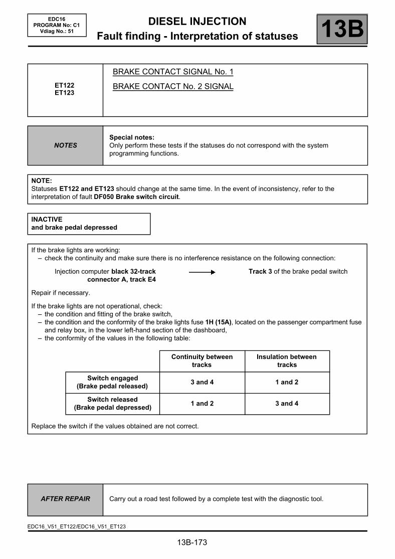
DIESEL INJECTIONFault finding - Interpretation of statuses 13B
13B-173
EDC16PROGRAM No: C1
Vdiag No.: 51
ET122ET123
BRAKE CONTACT SIGNAL No. 1
BRAKE CONTACT No. 2 SIGNAL
NOTESSpecial notes:Only perform these tests if the statuses do not correspond with the system programming functions.
NOTE:Statuses ET122 and ET123 should change at the same time. In the event of inconsistency, refer to the interpretation of fault DF050 Brake switch circuit.
INACTIVEand brake pedal depressed
If the brake lights are working:– check the continuity and make sure there is no interference resistance on the following connection:
Injection computer black 32-trackconnector A, track E4
Track 3 of the brake pedal switch
Repair if necessary.
If the brake lights are not operational, check:– the condition and fitting of the brake switch,– the condition and the conformity of the brake lights fuse 1H (15A), located on the passenger compartment fuse
and relay box, in the lower left-hand section of the dashboard,– the conformity of the values in the following table:
Continuity between tracks
Insulation between tracks
Switch engaged(Brake pedal released)
3 and 4 1 and 2
Switch released(Brake pedal depressed)
1 and 2 3 and 4
Replace the switch if the values obtained are not correct.
AFTER REPAIR Carry out a road test followed by a complete test with the diagnostic tool.
EDC16_V51_ET122/EDC16_V51_ET123
DIESEL INJECTIONFault finding - Interpretation of statuses 13B
13B-174
EDC16PROGRAM No: C1
Vdiag No.: 51
ET122 ET123
CONTINUED
ACTIVEand brake pedal released
If the brake lights are working:– check the continuity and make sure there is no interference resistance on the following connection:
Injection computer black 32-trackconnector A, track E4
Track 3 of the brake pedal switch
Repair if necessary.
If the brake lights are not working.check the condition and fitting of the brake light switch and brake light fuse,remove the brake light switch and check that it is operating correctly:
Continuity between tracks
Insulation between tracks
Switch engaged(Brake pedal released)
3 and 4 1 and 2
Switch released(Brake pedal depressed)
1 and 2 3 and 4
Replace the switch if the values obtained are not correct.
AFTER REPAIR Carry out a road test followed by a complete test with the diagnostic tool.

DIESEL INJECTIONFault finding - Interpretation of statuses 13B
13B-175
EDC16PROGRAM No: C1
Vdiag No.: 51
ET233
CLUTCH PEDAL
NOTESSpecial notes:Only perform these tests if the statuses do not correspond with the system programming functions.
RELEASEDand clutch pedal depressed
Check the condition and fitting of the clutch pedal switch.Check the following connection for continuity and make sure there is no interference resistance:
Injection computer black, 32-trackconnector A, track C4
Track 1 Clutch connector
Check for earth on track 2 of the clutch pedal switch connector.
Repair if necessary.Remove the clutch pedal switch and check that it is functioning correctly.
Continuity between tracks
Insulation between tracks
Switch engaged(Brake pedal released)
1 and 2
Switch released(Brake pedal depressed)
1 and 2
Replace the clutch pedal switch if necessary.
AFTER REPAIR Carry out a road test followed by a complete test with the diagnostic tool.
EDC16_V51_ET233

DIESEL INJECTIONFault finding - Interpretation of statuses 13B
13B-176
EDC16PROGRAM No: C1
Vdiag No.: 51
ET233CONTINUED
DEPRESSEDand clutch pedal released
Check the condition and fitting of the clutch pedal switch,Remove the clutch pedal switch and check that it is functioning correctly.
Continuity between tracks
Insulation between tracks
Switch engaged(Brake pedal released)
1 and 2
Switch released(Brake pedal depressed)
1 and 2
Replace the switch if necessary.
DEPRESSEDorRELEASEDand vehicle fitted with an automatic gearbox
Non-conformity of the clutch switch signal can cause the engine to race during gear changes. If the fault is still present, contact Techline.
Run a multiplex network test (see 88B, Multiplex).If the fault is still present, run fault finding on the automatic gearbox (see 23A, AUTOMATIC GEARBOX).
AFTER REPAIR Carry out a road test followed by a complete test with the diagnostic tool.
DIESEL INJECTIONFault finding - Interpretation of statuses 13B
DONE
13B-177
EDC16PROGRAM No: C1
Vdiag No.: 51
ET238
SYNCHRONISATION
NOTESSpecial notes:Only perform these tests if the statuses do not correspond with the system programming functions.
WARNINGSynchronisation is carried out during the engine starting phase. This is established between the camshaft position sensor and the TDC sensor.Once this synchronisation has been carried out, it enables the computer to identify cylinder no. 1 and to calculate the precise position of the cylinder's Top Dead Centre.
NOT DONE
When the engine is stopped but the ignition switched on, cylinder no. 1 is no longer indicated.
Status ET238 is NOT DONE; synchronisation between the crankshaft and the camshaft has not been carried out.
Synchronisation is carried out during the engine starting phase.Cylinder No. 1 is indicated and synchronisation will be performed once the engine is started.
Status ET238 is DONE.
If status ET238 remains NOT DONE after several attempts at starting the engine, consult the interpretation of the following faults:
– DF005 Engine speed sensor circuit.– DF097 Camshaft sensor circuit.
If the engine does still not start, consult the Customer complaints section, ALP2 Starting faults.
AFTER REPAIR Carry out a road test followed by a complete test with the diagnostic tool.
EDC16_V51_ET238

DIESEL INJECTIONFault finding - Interpretation of statuses 13B
NO
13B-178
EDC16PROGRAM No: C1
Vdiag No.: 51
ET341
IMMOBILISER CODE PROGRAMMED
NOTESSpecial notes:Only perform these tests if the statuses do not correspond with the system programming functions.
YES Status ET341 becomes YES if dialogue is established between the UCH and the injection computer and the card code is recognised.The engine is only authorised to start if the code is recognised by the UCH computer and status ET003 Engine immobiliser is INACTIVE.
The code remains NO if dialogue between the UCH and the injection computer is not possible. Status ET003 Engine immobiliser is ACTIVE.
The cause of the malfunction may be due to the incorrect programming of the cards, (see 97B, Passenger compartment connection unit, configuration and programming); follow the card programming procedure.
If the malfunction is not due to the card codes, test the multiplex network (when fault finding is carried out for functions) and check that there is dialogue between the UCH, the Protection and Switching Unit and the injection computer.If dialogue is not established, contact the Techline.
AFTER REPAIR Carry out a road test followed by a complete test with the diagnostic tool.
EDC16_V51_ET341

DIESEL INJECTIONFault finding - Interpretation of statuses 13B
DECREASE
13B-179
EDC16PROGRAM No: C1
Vdiag No.: 51
ET413
CRUISE CONTROL/SPEED LIMITER FUNCTION
NOTESSpecial notes:Only perform these tests if the statuses do not correspond with the system programming functions.
INCREASE Status ET413 becomes INCREASE when the cruise control + button is pressed. This button is situated to the left of the steering wheel.
If status ET413 does not become INCREASE, check the condition of the ±±±± cruise control button and its connector. Repair if necessary.
For removing the driver's airbag and carrying out all relating operations safely (see 88C, Airbag - pretensioners).Repair if necessary.
Measure the resistance of the following connection, after pressing the + button:
Injection computer black 32-trackconnector A, track D2
±±±± button, Track A1
If the resistance is not approximately 300 ΩΩΩΩ, check the continuity of the connection when the button is not pressed.If there is continuity, replace the ±±±± control button.If the connection is broken, repair it.
Status ET413 becomes MINUS when the cruise control - button is pressed. This button is situated to the left of the steering wheel.
If status ET413 does not change to DECREASE, check the condition of the ±±±± cruise control button and its connector. Repair if necessary.
For removing the driver's airbag and carrying out all relating operations safely (see 88C, Airbag - pretensioners).Repair if necessary.
Measure the resistance of the following connection, after pressing the - button:
Injection computer black 32-trackconnector A, track D2
±±±± button, Track A2
If the resistance is not approximately 100 ΩΩΩΩ, check the continuity of the connection when the button is not pressed.If there is continuity, replace the ±±±± control button.If the connection is broken, repair it.
AFTER REPAIR Carry out a road test followed by a complete test with the diagnostic tool.
EDC16_V51_ET413
DIESEL INJECTIONFault finding - Interpretation of statuses 13B
RESUME
13B-180
EDC16PROGRAM No: C1
Vdiag No.: 51
ET413CONTINUED
SUSPEND Status ET413 becomes CANCEL when the 0 cruise control button is pressed. This button is situated to the right of the steering wheel.
If status ET413 does not change to CANCEL, check the R/0 button of the cruise control, and the condition of its connector. Repair if necessary.
For removing the driver's airbag and carrying out all relating operations safely (see 88C, Airbag - pretensioners).Repair if necessary.
Measure the resistance of the following connection, after pressing the 0 button:
Injection computer black 32-trackconnector A, track D2
R/0 button Track A2
If the resistance is not approximately 0 ΩΩΩΩ, replace the R/0 control button.If the connection is broken, repair it.
Status ET413 becomes RESTART when the R cruise control button is pressed. This button is situated to the right of the steering wheel.
If status ET413 does not change to RESUME, check the condition of the R/0 cruise control button and its connector. Repair if necessary.
For removing the driver's airbag and carrying out all relating operations safely (see 88C, Airbag - pretensioners).Repair if necessary.
Measure the resistance of the following connection, after pressing the R button:
Injection computer black 32-trackconnector A, track D2
R/0 button Track A2
If the resistance is not approximately 900 ΩΩΩΩ, check the continuity of the connection when the button is not pressed.If there is continuity, then replace the R/0 control button.If the connection is broken, repair it.
AFTER REPAIR Carry out a road test followed by a complete test with the diagnostic tool.

DIESEL INJECTIONFault finding - Interpretation of statuses 13B
STATUS 3
STATUS 2
ET556
DRIVER'S DEACTIVATION OF THE CRUISE CONTROL/SPEED LIMITER
NOTESSpecial notes:Apply the conformity check to see if the statuses are consistent with the operating programs of the system.
Note:Cruise control remains active as long as the vehicle speed does not exceed 18 mph (30 km/h).Status ET556 details 6 causes for cruise control deactivation.IMPORTANTTo reinitialise the deactivations stored by the injection computer, use command RZ007 Fault memory.
STATUS 1
13B-181
EDC16PROGRAM No: C1
Vdiag No.: 51
AFTER REPAIR Carry out a road test followed by a complete test with the diagnostic tool.
EDC16_V51_ET556
Brake pedal depressed
The cruise control function is deactivated each time the brake pedal is depressed.Status ET556 becomes STATUS 1, when the vehicle is being driven, with cruise control active and the brake pedal depressed.If status ET556 becomes STATUS 1 without depressing the brake pedal, consult the interpretation of statuses ET122 and ET123 Brake contact no. 1 and no. 2 signal.
Traction control request
If the vehicle being diagnosed is fitted with traction control, the cruise control function is deactivated each time traction control is selected.Status ET556 changes to STATUS 2, when driving, with cruise control active and traction control requested.If status ET556 becomes STATUS 2 with no traction control request (see 38C, Anti-lock Braking System).
Suspend button pressed
Status ET556 changes to STATUS 3 when driving with Cruise control/Speed limiter active, if the driver presses the Cruise control/Speed limiter 0 button.If status ET556 becomes STATUS 3 without pressing the 0 button on the cruise control/speed limiter, consult the interpretation of status ET413 Cruise control/Speed limiter Function and run fault finding on the R/0 button of the cruise control/speed limiter.
DIESEL INJECTIONFault finding - Interpretation of statuses 13B
STATUS 6
STATUS 5
13B-182
EDC16PROGRAM No: C1
Vdiag No.: 51
ET556CONTINUED
STATUS 4 Clutch pedal depressed
MANUAL GEARBOX ONLYThe cruise control function is deactivated if the gearbox is no longer coupled to the engine (clutch pedal depressed).Status ET556 becomes STATUS 4 when driving, with cruise control active and the clutch pedal depressed.If status ET556 becomes STATUS 4 without depressing the clutch pedal, consult the interpretation of status ET233 Clutch pedal.
Gear lever in neutral position
Status ET556 changes to STATUS 5, when driving, with cruise control active and– if the driver puts the gear lever in neutral on a MANUAL GEARBOX without
declutching or,– if gear lever is in neutral on an automatic transmission.This deactivates cruise control.If status ET556 becomes STATUS 5 without putting the gear lever in neutral on a manual gearbox without declutching, or without neutral on an automatic gearbox, contact the Techline.
Inconsistency between the request and the vehicle speed
Status ET556 changes to STATUS 6 if the computer detects too great a difference between the speed requested by the driver and the vehicle speed.This may occur when driving, with cruise control active and where the difference between speeds is great.If status ET556 changes to STATUS 6 without a great difference in the speeds, contact the Techline.
AFTER REPAIR Carry out a road test followed by a complete test with the diagnostic tool.

DIESEL INJECTIONFault finding - Interpretation of statuses 13B
STATUS 3
STATUS 2
13B-183
EDC16PROGRAM No: C1
Vdiag No.: 51
ET557
CRUISE CONTROL/SPEED LIMITER DEACTIVATION BY FUNCTION
NOTESSpecial notes:Only perform these tests if the statuses do not correspond with the system programming functions.
Note:Cruise control remains deactivated as long as the vehicle speed does not exceed 18 mph (30 km/h). Status ET557 gives 3 causes of cruise control deactivation.IMPORTANTTo reinitialise the deactivations stored by the injection computer, use command RZ007 Fault memory.
STATUS 1 Cruise control or speed limiter fault
If status ET557 is STATUS 1, refer to the interpretation of status ET042 Cruise control/speed limiter and ET413 Cruise control/speed limiter function, to test the components of the cruise control system and find the faulty one.If status ET557 changes to STATUS 1, deal with the faults present or stored in the computer.If the fault is still present, contact the Techline.
Fault detected by the injection computer
Status ET557 changes to STATUS 2 if the injection computer detects a fault on the injection system:– faults in the engine speed sensor or camshaft,– accelerator pedal faults,– engine speed lower than 1000 rpm,– engine speed greater than 4700 rpm.Carry out a multiplex network test, then an injection system test, and carry out fault finding on any faults.If the fault is still present, contact the Techline.
Invalid vehicle speed
Status ET557 changes to STATUS 3 if the vehicle speed received by the computer is invalid.Carry out fault finding on the ABS computer.If faults are present (see 38C, Anti-lock braking system).If the fault is still present, contact the Techline.
AFTER REPAIR Carry out a road test followed by a complete test with the diagnostic tool.
EDC16_V51_ET557

DIESEL INJECTIONFault finding - Interpretation of statuses 13B
STATUS 18
STATUS 20
STATUS 21
STATUSES 11, 22
STATUS 8
STATUSES 4, 17
STATUS 2
STATUSES 3 14, 16
STATUSES 1, 5, 6, 7, 9, 10, 12, 13, 15,
19, 23, 24
13B-184
EDC16PROGRAM No: C1
Vdiag No.: 51
ET651
EGR PROGRAMMING CUT-OFF
NOTESSpecial notes:Only perform these tests if the status does not correspond with the system programming functions.
NONE No EGR cut-off, the EGR valve is working properly in accordance with the computer programs.
Switch off the ignition and wait 1 minute.Switch the ignition on and check for faults.Check the engine battery voltage with the engine stopped and then running.If no faults are present or stored, restart the vehicle and test at idle speed.Do not accelerate too much and reach an engine speed that is too high.
Accelerate above idling speed for a few seconds.
Check that the clutch pedal (ET233 Clutch pedal) has not been depressed and that the vehicle has completely stopped.
Test the present and stored faults and repair.
Reinitialise the EGR offsets by consulting the interpretation of commandSC036 Reinitialisation of programming and select EGR valve".
Allow the engine to heat up until this cut-off disappears.
Check that the particle filter regeneration has finished.
Allow the engine to cool until this cut-off disappears.
Too low atmospheric pressure, the EGR valve is disabled.
AFTER REPAIR Carry out a road test followed by a complete test with the diagnostic tool.
EDC16_V51_ET651
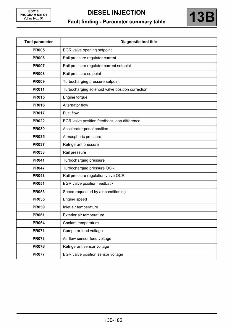
DIESEL INJECTIONFault finding - Parameter summary table 13B
13B-185
EDC16PROGRAM No: C1
Vdiag No.: 51Fault finding - Parameter summary table
Tool parameter Diagnostic tool title
PR005 EGR valve opening setpoint
PR006 Rail pressure regulator current
PR007 Rail pressure regulator current setpoint
PR008 Rail pressure setpoint
PR009 Turbocharging pressure setpoint
PR011 Turbocharging solenoid valve position correction
PR015 Engine torque
PR016 Alternator flow
PR017 Fuel flow
PR022 EGR valve position feedback loop difference
PR030 Accelerator pedal position
PR035 Atmospheric pressure
PR037 Refrigerant pressure
PR038 Rail pressure
PR041 Turbocharging pressure
PR047 Turbocharging pressure OCR
PR048 Rail pressure regulation valve OCR
PR051 EGR valve position feedback
PR053 Speed requested by air conditioning
PR055 Engine speed
PR059 Inlet air temperature
PR061 Exterior air temperature
PR064 Coolant temperature
PR071 Computer feed voltage
PR073 Air flow sensor feed voltage
PR076 Refrigerant sensor voltage
PR077 EGR valve position sensor voltage

DIESEL INJECTIONFault finding - Parameter summary table 13B
13B-186
EDC16PROGRAM No: C1
Vdiag No.: 51
Tool parameter Diagnostic tool title
PR079 Atmospheric pressure sensor voltage
PR080 Rail pressure sensor voltage
PR081 Inlet temperature sensor voltage
PR084 Coolant temperature sensor voltage
PR089 Vehicle speed
PR125 Power absorbed by the air conditioning compressor
PR128 First EGR valve offset
PR129 Last EGR valve offset
PR130 Cruise control setpoint
PR131 EGR air flow variation
PR132 Air flow
PR146 Inlet air flow
PR147 Pedal potentiometer voltage gang 1
PR148 Pedal potentiometer voltage gang 2
PR157 Fuel flow setpoint
PR171 Air flow setpoint for EGR
PR190 Engine idle speed setpoint.
PR213 Rail pressure loop difference
PR220 EGR valve OCR
PR358 Sensor reference voltage
PR364 Cylinder no. 1 fuel flow correction
PR365 Cylinder no. 4 fuel flow correction
PR385 Exhaust pipe flow
PR405 Cylinder no. 2 fuel flow correction
PR406 Cylinder no. 3 fuel flow correction
PR417 Air inlet valve OCR
PR420 Damper valve error counter
PR672 Damper valve position setpoint
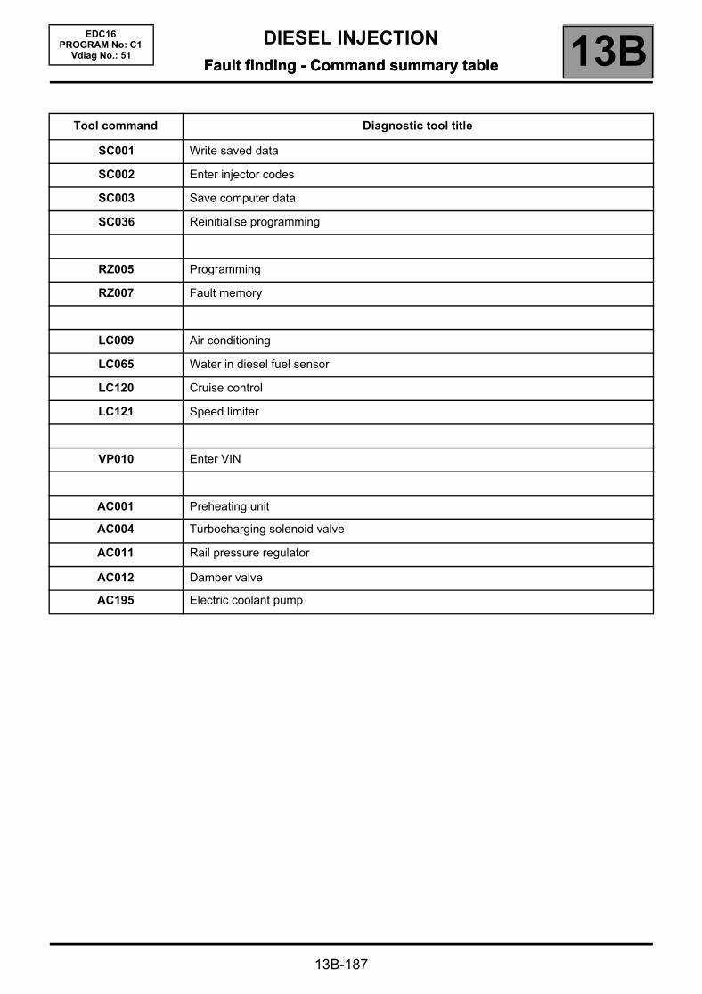
DIESEL INJECTIONFault finding - Command summary table 13B
13B-187
EDC16PROGRAM No: C1
Vdiag No.: 51Fault finding - Command summary table
Tool command Diagnostic tool title
SC001 Write saved data
SC002 Enter injector codes
SC003 Save computer data
SC036 Reinitialise programming
RZ005 Programming
RZ007 Fault memory
LC009 Air conditioning
LC065 Water in diesel fuel sensor
LC120 Cruise control
LC121 Speed limiter
VP010 Enter VIN
AC001 Preheating unit
AC004 Turbocharging solenoid valve
AC011 Rail pressure regulator
AC012 Damper valve
AC195 Electric coolant pump

DIESEL INJECTIONFault finding - Interpretation of commands 13B
13B-188
EDC16PROGRAM No: C1
Vdiag No.: 51Fault finding - Interpretation of commands
SC001
WRITE SAVED DATA
NOTESAll data must be saved with command SC003 SAVE COMPUTER DATA for this command to be run.Writing is carried out after the computer has been reprogrammed or replaced.
Validating this command writes the data saved using command SC003 SAVE COMPUTER DATA.
The data is as follows:– vehicle idle speed,– injector calibration codes (if the vehicle is fitted with IMA),– programming of exhaust gas recirculation valve data,– options available on the vehicle and managed by the computer (E.g. air conditioning).
This data configures the computer and prevents:– engine malfunction after reprogramming or replacing the computer,– incorrect interpretation of the information given by the Clip diagnostic tool.
EDC16_V51_SC001

DIESEL INJECTIONFault finding - Interpretation of commands 13B
13B-189
EDC16PROGRAM No: C1
Vdiag No.: 51
SC002
ENTER INJECTOR CODES
NOTES
This command should be run after the injectors have been replaced and only if the vehicle has been configured with IMA.(ET104 USE OF INJECTOR CODES to YES).If this command is not performed, the DF276 INJECTOR CODE PROGRAMMING fault will be present.
WARNINGThe letters J and Q, and figures 0 and 9 are not used in IMA coding.If these characters are used the entry will be invalid.
Cylinder no. 1 is the cylinder located at the engine flywheel end.
Procedure to be followed:– Read the 6-character alphanumeric codes etched on the upper section of the injector bodies.– Use command SC002.– Select the cylinder number for the cylinder concerned in the Desired, column, then confirm.– Enter the injector code displayed for the cylinder.– Enter the new codes for each cylinder, then confirm.– When the command is completed, the modified codes appear in the Current column.– Check that the codes correspond to those read earlier.– If the codes entered appear in neither the Current column nor the Desired column, check the codes read and
make sure the data has been entered correctly,
The possible confusions are:
digit "1" with the letter "I"digit "8" with the letter "B"digit "5" with the letter "S"
– Exit fault finding mode.– Switch off the ignition and wait for 1 min.– Switch the ignition back on and check for faults.
– DF276 INJECTOR CODE PROGRAMMING should be stored.
If fault DF276 is still present, the command has not been performed correctly.Start the procedure again and follow the instructions.If the codes are still not recognised, check whether the computer's standby has been correctly set:Switch off the ignition and wait for 1 min.If the warning light flashes when the ignition is switched off, the computer has not been put on standby and the command will be ignored.If all these checks still do not enable the command to be confirmed, contact the Techline.
EDC16_V51_SC002

DIESEL INJECTIONFault finding - Interpretation of commands 13B
13B-190
EDC16PROGRAM No: C1
Vdiag No.: 51
SC003
SAVE COMPUTER DATA
NOTES The data is saved before computer reprogramming or the computer is replaced.
On the CLIP tool, select the SC003 Save computer data.If the following message appears:"a saved file exists, do you want to overwrite this data?"(this file corresponds to the last save made on the tool)Select YES.
Confirming this command saves the following vehicle-specific data:– injector codes,– the EGR valve data programming;– options available on the vehicle and managed by the computer (E.g. air conditioning).
This information will be saved on the CLIP tool.
After saving has finished, use the command SC001 Enter saved data to be able to set the new computer parameters, after programming and reprogramming.
EDC16_V51_SC003

DIESEL INJECTIONFault finding - Interpretation of commands 13B
13B-191
EDC16PROGRAM No: C1
Vdiag No.: 51
SC036
PROGRAMMING REINITIALISATION
NOTES
This command allows you to reinitialise the computer parameters according to the type of operation or the component repaired or replaced, such as:
– the EGR valve,– the damper valve.
Ignition on, engine stopped.
To run this command, select the SC036 Reinitialise programming scenario on the CLIP tool.
Procedure to be followed:– on the main screen, select the component to reinitialise after an operation (removing, refitting or replacing the
component),– select YES then OK to begin reinitialisation,– select Finish on the Configuration done screen to return to the main screen,– end of operation.
EDC16_V51_SC036
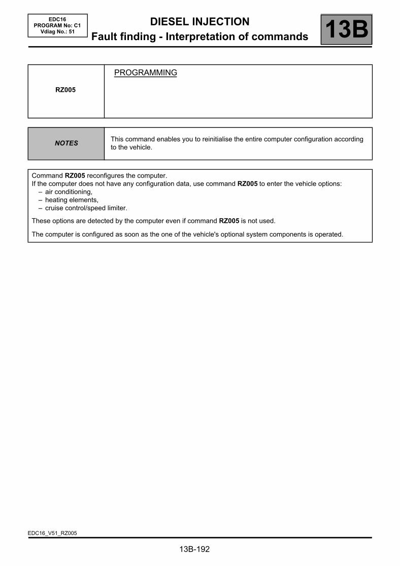
DIESEL INJECTIONFault finding - Interpretation of commands 13B
13B-192
EDC16PROGRAM No: C1
Vdiag No.: 51
RZ005
PROGRAMMING
NOTESThis command enables you to reinitialise the entire computer configuration according to the vehicle.
Command RZ005 reconfigures the computer.If the computer does not have any configuration data, use command RZ005 to enter the vehicle options:
– air conditioning,– heating elements,– cruise control/speed limiter.
These options are detected by the computer even if command RZ005 is not used.
The computer is configured as soon as the one of the vehicle's optional system components is operated.
EDC16_V51_RZ005
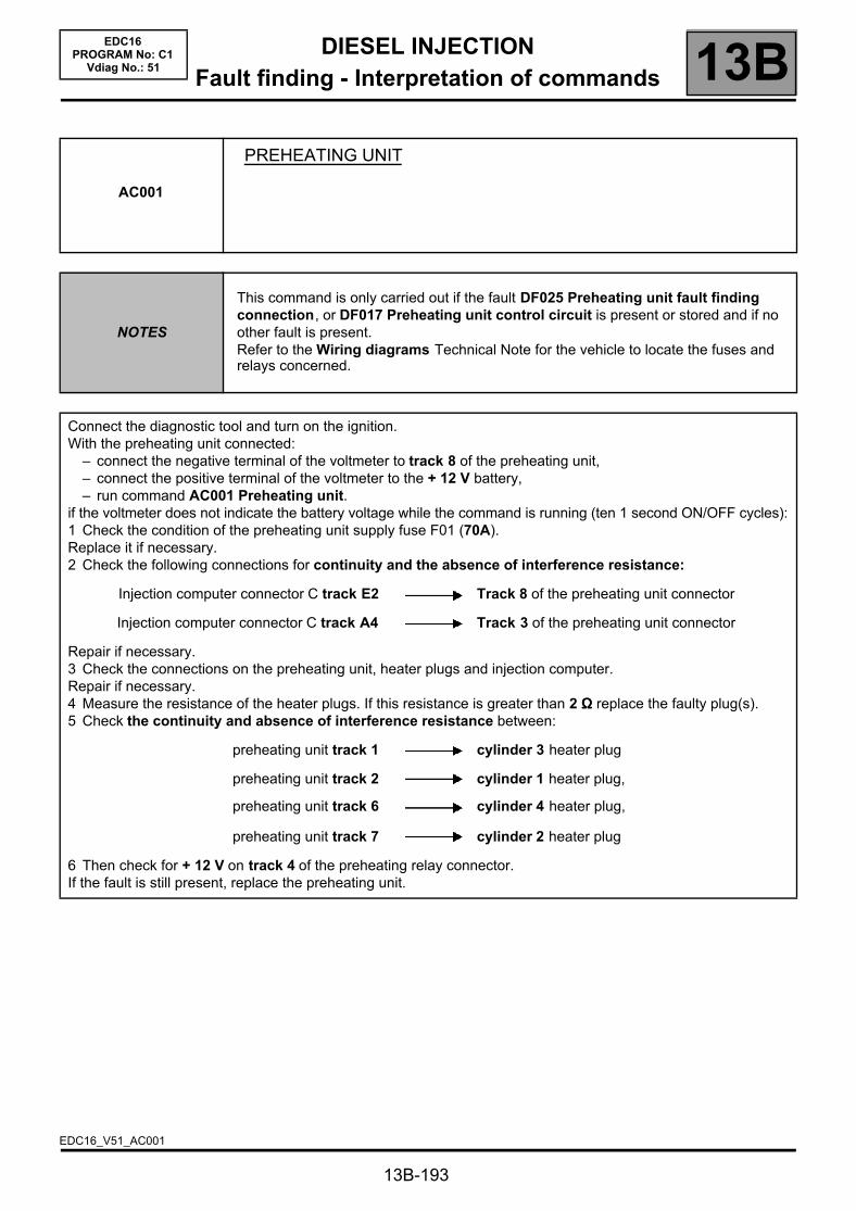
DIESEL INJECTIONFault finding - Interpretation of commands 13B
13B-193
EDC16PROGRAM No: C1
Vdiag No.: 51
AC001
PREHEATING UNIT
NOTES
This command is only carried out if the fault DF025 Preheating unit fault finding connection, or DF017 Preheating unit control circuit is present or stored and if no other fault is present.Refer to the Wiring diagrams Technical Note for the vehicle to locate the fuses and relays concerned.
Connect the diagnostic tool and turn on the ignition.With the preheating unit connected:
– connect the negative terminal of the voltmeter to track 8 of the preheating unit,– connect the positive terminal of the voltmeter to the + 12 V battery,– run command AC001 Preheating unit.
if the voltmeter does not indicate the battery voltage while the command is running (ten 1 second ON/OFF cycles):1 Check the condition of the preheating unit supply fuse F01 (70A).Replace it if necessary.2 Check the following connections for continuity and the absence of interference resistance:
Injection computer connector C track E2 Track 8 of the preheating unit connector
Injection computer connector C track A4 Track 3 of the preheating unit connector
Repair if necessary.3 Check the connections on the preheating unit, heater plugs and injection computer.Repair if necessary.4 Measure the resistance of the heater plugs. If this resistance is greater than 2 ΩΩΩΩ replace the faulty plug(s).5 Check the continuity and absence of interference resistance between:
preheating unit track 1 cylinder 3 heater plug
preheating unit track 2 cylinder 1 heater plug,
preheating unit track 6 cylinder 4 heater plug,
preheating unit track 7 cylinder 2 heater plug
6 Then check for + 12 V on track 4 of the preheating relay connector.If the fault is still present, replace the preheating unit.
EDC16_V51_AC001

DIESEL INJECTIONFault finding - Interpretation of commands 13B
13B-194
EDC16PROGRAM No: C1
Vdiag No.: 51
AC004
TURBOCHARGING SOLENOID VALVE
NOTES This command is used to check the turbocharging circuit.
This command checks that the turbocharger and the control circuit are working properly.
Introduction
1-Check the sealing of the high pressure air circuit:Pipes not joined or pierced, pressure sensor disconnected or poorly fitted (seal present), intercooler pierced. To test the intercooler: stabilise the engine speed between 3,500 and 4,000 rpm with the vehicle stopped and check that there are no leaks.
Check the resistance of the turbocharging limitation solenoid valve between tracks 1 and 2.Replace the solenoid valve if the resistance is not: 15.4 ΩΩΩΩ ±±±± 0.7 at 20 °°°°C.
Check the injection computer connections.Check for continuity and make sure there is no interference resistance on the following connection:
Injection computer grey 32-track connector C,track E1
Track 1 turbocharging solenoid valve
Repair if necessary.
Check for the presence of + 12 V after relay on track 2 of the turbocharging solenoid valve.
2 - Turbocharger control circuit check– With the engine stopped, make sure that the control rod is in the rest position.– Start the engine and make sure that the control rod actuates to the upper stop.– (when the engine is switched off, the control rod should return to the rest position)– If the control rod does not move correctly, carry out the following checks:
1) Vacuum pressure control check:– Disconnect the solenoid valve inlet hose and connect it to a pressure gauge.– Start the engine and run it at a stable idle speed.– If the vacuum pressure does not reach 800 mbar ±±±± 100: check the vacuum pressure circuit from the vacuum
pump.– Stop the engine, reconnect the inlet hoses and go to step no. 2.
2) Solenoid valve control check:– Disconnect the solenoid valve outlet hose.– Start the engine and run it at a stable idle speed.– Place your hand on the solenoid valve and block the outlet union with your thumb.– If you notice no solenoid valve vibration, check the operation of the computer output (step 5). Solenoid valve
operation check:– Connect the pressure gauge to the solenoid valve outlet union.– Start the engine and run it at a stable idle speed.If the vacuum pressure does not reach 800 mbar ±±±± 100, replace the solenoid valve.
EDC16_V51_AC004
DIESEL INJECTIONFault finding - Interpretation of commands 13B
13B-195
EDC16PROGRAM No: C1
Vdiag No.: 51
* Opening cyclic ratio signal
AC004CONTINUED
Turbocharger control circuit check (continued)
4) Turbocharger operation check:a) Connect a vacuum pump to the hose connected to the turbocharger control diaphragm.
Apply a vacuum of 800 ±±±± 100 mbar:If there is a leak, replace the turbocharger (diaphragm included).
b) Check the control rod movement and setting (see MR 364, Mechanics, 12B, Turbocharging).If the control rod is sticking, replace the turbocharger.
c) Engine cold and stopped:Remove the turbocharger inlet duct and check that the compressor turns freely on the axis.
d) If the fault persists:Check that the exhaust manifold is not leaking.Check that the exhaust is not blocked.Carry out the necessary repairs.
5) Computer output stage check: (solenoid valve connected).This operation can only be carried out if the checks indicated in step no. 2 are not conclusive.Either with the voltmeter: Connect the voltmeter earth lead on track 2 of the solenoid valve and the positive lead on track 1.Clear any solenoid valve fault then run command AC004: the voltmeter should display ten cycles of two successive voltages ~ = battery voltage X opening cycle ratio* in process.that is: ~ 2.5 V (opening cyclic ratio* of 20 %) then ~ 8.7 V (opening cyclic ratio* of 70 %).Or with the oscilloscope (at 5 V range/division and 1 ms/div time base): Connect the earth lead of the oscilloscope to the battery earth and the positive test pin to track 2 of the solenoid valve.Clear any solenoid valve faults, then run command AC004: the oscilloscope should display a square wave signal of 12.5 V in amplitude at a frequency of 140 Hz(with an opening cyclic ratio* passing from ~ 20 to ~ 70 %).If the measurement is correct, replace the solenoid valve.If the measurement does not show any control or continuous voltage, contact the Techline.
DIESEL INJECTIONFault finding - Interpretation of commands 13B
13B-196
EDC16PROGRAM No: C1
Vdiag No.: 51
* Opening cyclic ratio signal
AC011
RAIL PRESSURE REGULATOR
NOTESThis command is used to check:
– the operation of the pressure regulator,– and the high pressure injection circuit.
Step 1
Measure the pressure regulator resistance between tracks 1 and 2.– Replace the regulator if the resistance is not approximately: 3 ΩΩΩΩ ±±±± 0.5 at 20 °°°°C.Check the continuity and absence of interference resistance of the following connections:
Injection computer brown 48-track connector B,track M4
track 2 of the rail pressure regulator connector
+ 12 V after relay track 1 of the rail pressure regulator connector
If, when running command AC011, you can hear a slight whistling noise and a crunching noise from the pressure regulator, go to step 2. Otherwise, ensure that the computer output stage is functioning correctly:Using a voltmeter:With the solenoid valve connected, connect the voltmeter earth lead to track 2 of the fuel pressure solenoid valve and the positive cable to track 1. Clear any fuel pressure solenoid valve faults, then run command AC011: the voltmeter should display two successive voltages: ~ 2.5 V for an opening cyclic ratio of 20 % then ~ 8.75 V
for an opening cyclic ratio* of 70 % (ten cycles).Or using an oscilloscope (range 5 V/division and with time base 1 ms/division):With the solenoid valve connected, connect the oscilloscope earth to the battery earth and the positive contact point on track 2 of the fuel pressure solenoid valve; clear any fuel pressure solenoid valve faults then run command AC011: the oscilloscope should display a square wave signal with an amplitude of 12.5 V at a frequency of 185 Hz (with
an OCR* passing from 20 to 70 %).If the measurement is correct, replace the regulator.If the measurement is not correct, contact the Techline.
EDC16_V51_AC011

DIESEL INJECTIONFault finding - Interpretation of commands 13B
13B-197
EDC16PROGRAM No: C1
Vdiag No.: 51
AC011CONTINUED
Step 2
In the event of rail overpressure:Check the injectors are working:see test 10: POOR INJECTOR OPERATION.
Check that the rail pressure sensor is operating correctly:Fault interpretation DF007 RAIL PRESSURE SENSOR CIRCUIT.Carry out the necessary repairs.If these checks do not reveal any faults, and if the fault is still present, replace the rail pressure sensor.In the event of rail underpressure:
Check that the rail pressure sensor is operating correctly:Fault interpretation DF007 RAIL PRESSURE SENSOR CIRCUIT.Check the low pressure diesel circuit priming.Check the conformity of the diesel filter connections.Check the condition of the filter (clogging and water saturation).Check there are no air bubbles between the filter and the high pressure pump.Check the sealing of the high pressure and low pressure diesel circuit.(odour and visual inspections): pump body, overpressure valve, pipes, rail and injector unions, injector wells.Check the conformity of the seal fitting on the pressure regulator.Check the injectors are working:see test 10: POOR INJECTOR OPERATION.Carry out the necessary repairs.If these checks do not reveal any faults, and if the fault is still present, replace the rail pressure sensor.

DIESEL INJECTIONFault finding - Interpretation of commands 13B
13B-198
EDC16PROGRAM No: C1
Vdiag No.: 51
AC012
DAMPER VALVE
NOTES This command allows you to check the operation of the damper valve.
– Measure the resistance of the damper valve solenoid valve between tracks 1 and 2.Replace the solenoid valve if the resistance is not 46 ±±±± 3 ΩΩΩΩ at + 25 °°°°C.
– Check the continuity and the absence of interference resistance on the connections between:
Injection computer, brown 48-track connectorB, track M1
track 1 of the damper valve solenoid valve connector
+ 12 V after relay track 2 of the damper valve solenoid valve connector
A) Engine running at idle speed
Make sure that there is a pressure of ~ 900 mbar on the solenoid valve inlet hose.Make the necessary repairs (pressure circuit conformity and seal).
B) With the vehicle ignition on, engine stopped
Make sure the damper valve is open.If not, clean or replace the air vent unit.Disconnect the solenoid valve inlet and outlet hoses,Connect a vacuum pump to the inlet union and apply a pressure of ~ 900 mbarIf there is a leak, replace the solenoid valve.Run command AC012.If the solenoid valve opens (vacuum pump pressure gauge returns to atmospheric pressure), go to step C.
Otherwise, with the solenoid valve connected, check operation of the computer output stage with a voltmeter:
Voltmeter earth cable track 1 of the solenoid valve
Voltmeter positive lead track 2 of the solenoid valve
Clear any solenoid valve faults,Run command AC012.The voltmeter should display ten ON-OFF cycles (8.75 V then 2.5 V).If the measurement is correct, replace the solenoid valve.If the measurement shows is not controlled, contact the Techline.
C) Vehicle with ignition off
Connect a vacuum pump to the flap control diaphragm and apply a pressure of ~ 900 mbar:If the diaphragm does not maintain the vacuum, replace the air vent unit (the diaphragm cannot be disconnected).If the diaphragm maintains the vacuum and the flap does not operate, clean or replace the air vent unit.If the diaphragm maintains the underpressure and the valve operates, then operate it several times to ensure that there is no blockage.Check for clogging of the air vent unit and its valve, and clean if necessary.
EDC16_V51_AC012
DIESEL INJECTIONFault finding - Interpretation of commands 13B
13B-199
EDC16PROGRAM No: C1
Vdiag No.: 51
AC195
ELECTRIC COOLANT PUMP
NOTES This command allows you to check the operation of the electric coolant pump.
Test the electric coolant pump relay (A 20A) and check it is operating correctly.Check the injection computer connections.Repair if necessary.
Check the continuity between the following connections: Tracks B1 and B5 of the coolant pump relay mounting.
If the checks yield the correct results, check the continuity and absence of interference resistance on the following connections:
Injection computer brown 48-track connector B,track H4
Track B2 of the coolant pump relay mounting
Injection supply relay mounting, Track 5 Track B1 of the coolant pump relay mounting
Injection supply relay mounting, Track 5 Track B5 of the coolant pump relay mounting
Turbocharger bearing coolant pump connector,Track 1
Track B3 of the coolant pump relay mounting
Turbocharger bearing coolant pump connector,Track 2
Earth
Repair if necessary.If the fault is still present, contact the Techline.
EDC16_V51_AC195
DIESEL INJECTIONFault finding - Customer complaints 13B
13B-200
EDC16PROGRAM No: C1
Vdiag No.: 51Fault finding - Customer complaints
NOTES
Before dealing with this customer complaint, check that there are no faults, and the conformity (or otherwise) of the parameters and statuses using the diagnostic tool.If the customer complaint is not eliminated, then proceed according to the corresponding fault finding chart.
NO DIALOGUE WITH ENGINE MANAGEMENT COMPUTER ALP1
STARTING FAULT OR STARTING IMPOSSIBLE ALP 2
INJECTION NOISE ALP3
POOR PERFORMANCE ALP4
IRREGULAR ENGINE OPERATION ALP5
EXTERNAL LEAKS FROM THE FUEL CIRCUIT ALP6
ROUGH IDLE ALP7
OIL LEAKS FROM THE TURBOCHARGER ALP8

DIESEL INJECTIONFault finding - Fault Finding Chart 13B
13B-201
EDC16PROGRAM No: C1
Vdiag No.: 51Fault finding - Fault Finding Chart
ALP1 No dialogue with engine management computer
Try to establish dialogue with a computer on another vehicle to make sure that the diagnostic tool is not faulty.
Check the battery voltage and make the necessary adjustments to obtain a correct voltage (9.5 V < Battery voltage < 17.5 V).
If the tool is not at fault, and dialogue cannot be established with any other computer on the same vehicle, the cause could be a faulty computer interfering on the multiplex network.Disconnect the engine management computer.Try to establish dialogue with another computer.If the fault is still present, reconnect the computer and proceed by elimination by successively disconnecting all the following computers (according to wiring diagram and equipment): Air conditioning, Airbag, ABS and ESP, UCH, instrument panel, central communication unit, proximity sensor.Try to establish a dialogue between each disconnection:If, after a disconnection, you manage to establish dialogue, perform the fault finding procedure for the relevant computer.
Perform fault finding on the multiplex network using the diagnostic tool.
Check for the presence and the condition of the injection fuses on the UPC, and/or the engine fuse box.Check the connection of the computer connectors and the condition of its connections.Check the injection computer earths (quality, oxidation, earth bolts secure on the battery terminal).Check that the supply to the computer is correct:Earth on tracks H1, G4 and H4 of black 32-track connector A.+ after ignition feed on track D1 of black 32 track connector A.
Ensure that the supply to the diagnostic socket is correct:+ before ignition feed on track 16.+ after ignition feed on track 1.Earth connection on tracks 4 and 5.
If dialogue has still not been established after these checks, contact Techline.
AFTER REPAIR Carry out a road test followed by a complete check with the diagnostic tool.
EDC16_V51_ALP1

DIESEL INJECTIONFault finding - Fault Finding Chart 13B
13B-202
EDC16PROGRAM No: C1
Vdiag No.: 51
ALP 2 Starting difficult or impossible
NOTES
Before dealing with this customer complaint, check that there are no faults, and the conformity (or otherwise) of the parameters and statuses using the diagnostic tool.If the customer complaint is not eliminated, perform the following checks.
Is starting difficult or impossible?impossible B
(Go to continued 2)
difficult
PART A:
Check the engine earths.Ensure that engine speed reaches 250 rpm with the starter motor, as displayed on the parameter screen (PR055 Engine speed).If the engine speed is less than 250 rpm, refer to Technical Note 6014A Charging circuit check, Starter motor fault finding, Starter motor (formerly Technical Note 3632A).
If the engine speed under CLIP is zero and the engine is running, check the resistance of the engine speed sensor between tracks 1 and 2 or A and B:Replace the sensor if its resistance is not: 800 ±±±± 80 ΩΩΩΩ at + 20 °°°°C.
Check the continuity of the following connections:
engine management computer, connector Btrack D1
track A of the engine speed sensor
engine management computer, connector Btrack C1
track B of the engine speed sensor
Check that the engine earthing is in order (oxidation, tightness, etc.).Check the mounting, air gap and condition (overheating) of the sensor.Replace if necessary.
Check the synchronisation of the camshaft sensors and the engine speed sensors with the display of ET238 Synchronisation.If synchronisation is not active, refer to the checks described in DF195 Camshaft/engine speed consistency.
Check the fuel circuit sealing.If the fault is still present, see DF053 Rail pressure regulation function 2.def, stage 4.
AFTER REPAIR Carry out a road test followed by a complete check with the diagnostic tool.
EDC16_V51_ALP2
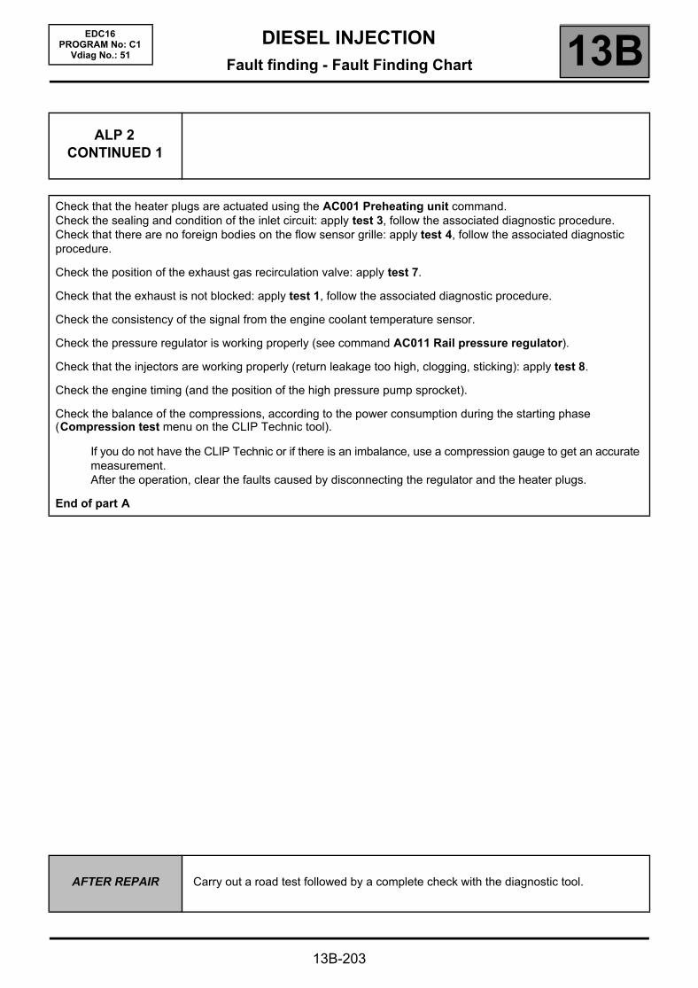
DIESEL INJECTIONFault finding - Fault Finding Chart 13B
13B-203
EDC16PROGRAM No: C1
Vdiag No.: 51
ALP 2CONTINUED 1
Check that the heater plugs are actuated using the AC001 Preheating unit command.Check the sealing and condition of the inlet circuit: apply test 3, follow the associated diagnostic procedure.Check that there are no foreign bodies on the flow sensor grille: apply test 4, follow the associated diagnostic procedure.
Check the position of the exhaust gas recirculation valve: apply test 7.
Check that the exhaust is not blocked: apply test 1, follow the associated diagnostic procedure.
Check the consistency of the signal from the engine coolant temperature sensor.
Check the pressure regulator is working properly (see command AC011 Rail pressure regulator).
Check that the injectors are working properly (return leakage too high, clogging, sticking): apply test 8.
Check the engine timing (and the position of the high pressure pump sprocket).
Check the balance of the compressions, according to the power consumption during the starting phase (Compression test menu on the CLIP Technic tool).
If you do not have the CLIP Technic or if there is an imbalance, use a compression gauge to get an accurate measurement.After the operation, clear the faults caused by disconnecting the regulator and the heater plugs.
End of part A
AFTER REPAIR Carry out a road test followed by a complete check with the diagnostic tool.

DIESEL INJECTIONFault finding - Fault Finding Chart 13B
13B-204
EDC16PROGRAM No: C1
Vdiag No.: 51
ALP 2CONTINUED 2
Is there any diesel in the tank?
YES
Does the starter motor work properly?(Ensure that the engine speed reaches> ~ 250 rpm with starter motor in operation, PR055 Engine speed)
YES
Using the diagnostic tool, check the conformity of the immobiliser: ET003 Immobiliser must be INACTIVE.
ET003 not in order, or immobiliser warning light permanently on
ET003 in order (immobiliser code warning light off)
Consult the fault finding procedure for the engine immobiliser.
NOFill the tank with diesel fuel.Bleed the low and high pressure diesel circuit.
NOConsult Technical Note 6014A, Checking the charging circuit, 16A, Starter fault finding, Starter.
Continue the fault finding procedure with Part A of this fault finding chart.
AFTER REPAIR Carry out a road test followed by a complete check with the diagnostic tool.

DIESEL INJECTIONFault finding - Fault Finding Chart 13B
13B-205
EDC16PROGRAM No: C1
Vdiag No.: 51
ALP3 Injection noise
NOTES
Before dealing with this customer complaint, check that there are no faults, and the conformity (or otherwise) of the parameters and statuses using the diagnostic tool.If the customer complaint is not eliminated, perform the following checks.
If the injection noise occurs after starting from cold:Check the low pressure diesel circuit priming.Check the fuel heater supply.Check the operation of the preheating system.Check that fuel and engine temperatures are consistent.
If the injection noise occurs at idle speed:Check the condition of the injector connector and pressure regulator terminals.Check the conformity of the air flow signal: use the: PR132 Air flow fault finding procedures or apply test 3.
If the fault is still present, perform the injector fault finding procedure: apply test 8.
Does the injection noise occur at all engine speeds?Run fault finding on the injectors: apply test 8.Check the condition of the injector connector and pressure regulator terminals.Ensure that the correct fuel is being used:– Compare the fuel with unpolluted diesel fuel:
To detect petrol, solvent, thinner, sulphuric acid (fuel with a white colour), water or fuel oil.
If the diesel fuel is not correct: – Replace the diesel fuel.– Change the diesel filter.– Bleed the low and high pressure diesel circuit.
Check the conformity of the air flow signal: use the interpretation of the fault finding procedure PR132 Air flow.If the customer complaint is still present:Run command AC011 Rail pressure regulator.Then apply the conformity check to confirm:– the conformity of the fuel pressure between PR008 Rail pressure setpoint and PR038 Rail Pressure,– the conformity of the pump fuel flow between PR157 Fuel flow setpoint and PR017 Fuel flow.
If the fault is still present, contact the Techline.
AFTER REPAIR Carry out a road test followed by a complete check with the diagnostic tool.
EDC16_V51_ALP3
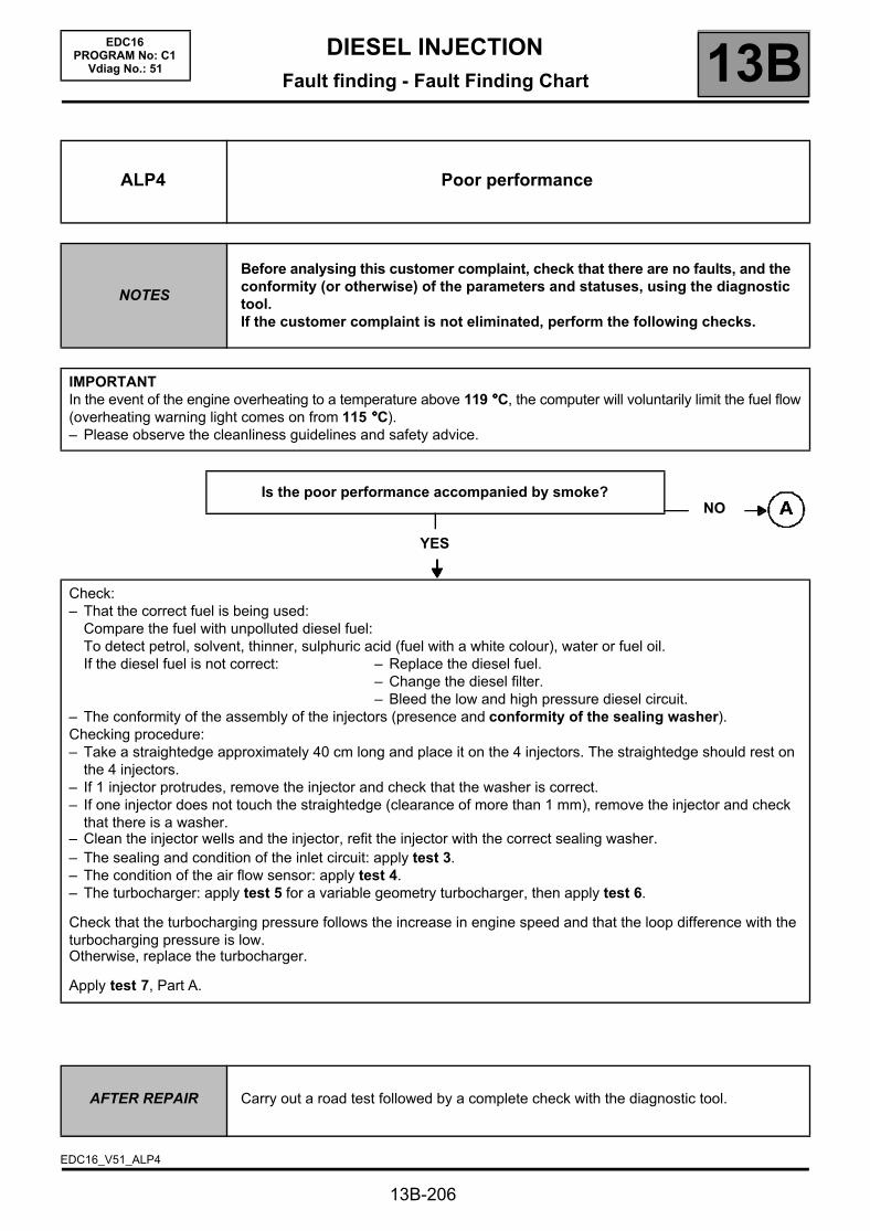
DIESEL INJECTIONFault finding - Fault Finding Chart 13B
13B-206
EDC16PROGRAM No: C1
Vdiag No.: 51
ALP4 Poor performance
NOTES
Before analysing this customer complaint, check that there are no faults, and the conformity (or otherwise) of the parameters and statuses, using the diagnostic tool.If the customer complaint is not eliminated, perform the following checks.
IMPORTANTIn the event of the engine overheating to a temperature above 119 °°°°C, the computer will voluntarily limit the fuel flow(overheating warning light comes on from 115 °°°°C).– Please observe the cleanliness guidelines and safety advice.
Is the poor performance accompanied by smoke?
YES
Check:– That the correct fuel is being used:
Compare the fuel with unpolluted diesel fuel:To detect petrol, solvent, thinner, sulphuric acid (fuel with a white colour), water or fuel oil.If the diesel fuel is not correct: – Replace the diesel fuel.
– Change the diesel filter.– Bleed the low and high pressure diesel circuit.
– The conformity of the assembly of the injectors (presence and conformity of the sealing washer).Checking procedure:– Take a straightedge approximately 40 cm long and place it on the 4 injectors. The straightedge should rest on
the 4 injectors.– If 1 injector protrudes, remove the injector and check that the washer is correct.– If one injector does not touch the straightedge (clearance of more than 1 mm), remove the injector and check
that there is a washer.– Clean the injector wells and the injector, refit the injector with the correct sealing washer.– The sealing and condition of the inlet circuit: apply test 3.– The condition of the air flow sensor: apply test 4.– The turbocharger: apply test 5 for a variable geometry turbocharger, then apply test 6.
Check that the turbocharging pressure follows the increase in engine speed and that the loop difference with the turbocharging pressure is low.Otherwise, replace the turbocharger.
Apply test 7, Part A.
NO
AFTER REPAIR Carry out a road test followed by a complete check with the diagnostic tool.
EDC16_V51_ALP4

DIESEL INJECTIONFault finding - Fault Finding Chart 13B
ALP4 CONTINUED
Is the engine running on all cylinders?
NO
Check the injector operation: apply test 11.
If the fault is still present
Check the conformity of the accelerator pedal position sensor, the brake pedal sensor, the atmospheric pressure sensor, the exhaust gas recirculation valve and the damper valve.– Check the consistency of the signal: of the air flow sensor, of the engine coolant temperature sensor, of the fuel
temperature sensor and of the engine speed.Check the connections, the continuity and absence of interference resistance on the air flow sensor (apply DF056 Air flow sensor circuit, 2.def), the engine coolant temperature sensor (apply DF001 Coolant circuit, 1.def), and the engine speed (apply DF195 Camshaft sensor/engine speed consistency, 2.def).Check: – That the diesel filter is not clogged (for the test, see DF053 Rail pressure regulation function
2.def).– That there are no leaks on the high and low pressure diesel circuits: apply test 3.– That the oil vapour rebreathing system is connected,– The flow regulator (blocked/seized, apply the interpretation for command: AC011 Rail pressure
regulator).– Check the timing setting (and the position of the high pressure pump sprocket) (see MR 364, Mechanics, 11A,
Top and front of engine).– Check the engine compression (balance of the cylinder compressions with the Compression test function on the
CLIP Technic tool).– Measure the engine compressions using the special tool.If the fault is still present, contact the Techline.
YES
13B-207
EDC16PROGRAM No: C1
Vdiag No.: 51
AFTER REPAIR Carry out a road test followed by a complete check with the diagnostic tool.

DIESEL INJECTIONFault finding - Fault Finding Chart 13B
13B-208
EDC16PROGRAM No: C1
Vdiag No.: 51
ALP5 Irregular engine operation
NOTES
Before dealing with this customer complaint, check that there are no faults, and the conformity (or otherwise) of the parameters and statuses using the diagnostic tool.If the customer complaint is not eliminated, perform the following checks.
If the engine races during gear changes, check, if there is a floor carpet, that this is not blocking the accelerator pedal, the brake pedal or the clutch pedal, then check the conformity of the clutch switch and the conformity of the accelerator pedal sensor when the pedal is released.Measure the resistance between tracks A and B of the engine speed sensor:Replace the sensor if its resistance is not: 800 ±±±± 80 ΩΩΩΩ at + 20 °°°°C.
Check the continuity of the following connections:
Engine management computer, connector Btrack B1
track A of the engine speed sensor
Engine management computer, connector Btrack C1
track B of the engine speed sensor
Check that the engine earthing is in order (oxidation, tightness, etc.).Check the mounting, air gap (check that the engine speed sensor - flywheel gap is 0.5 to 1.8 mm) and the condition of the sensor (heating).Replace if necessary.
Check the low pressure circuit.– Check the pressure regulation solenoid valve by applying section B of the Rough idle fault finding chart.
~ 1600 bar with full load on the accelerator.– Apply the procedure for checking the air flow; see conformity check.– Check the turbocharger: apply test 5 for a variable geometry turbocharger, then apply test 6.– Apply the procedure for checking the hydraulic circuit see conformity check.
If the fault persists:– Check the balance of the cylinders using the CLIP Technic function, Compression test physical measurements
icon.– Check the cylinder compressions if necessary using the special tool.
AFTER REPAIR Carry out a road test followed by a complete check with the diagnostic tool.
EDC16_V51_ALP5

DIESEL INJECTIONFault finding - Fault Finding Chart 13B
13B-209
EDC16PROGRAM No: C1
Vdiag No.: 51
ALP6 External leaks from the fuel circuit
NOTES
Before analysing this customer complaint, check that there are no faults, and the conformity (or otherwise) of the parameters and statuses, using the diagnostic tool.If the customer complaint is not eliminated, perform the following checks.IMPORTANTPlease observe the cleanliness guidelines and safety advice.
Procedure for checking for an external leak on the fuel circuit:Clean away traces of grease with clean thinner and wipe the part or parts concerned with cleaning cloths.Start the engine and raise the engine coolant temperature until the diesel fuel reaches 80 °°°°C.Stop the engine and check for traces of grease on the part or parts concerned.If there are such signs, replace the part or parts concerned.Bleed the fuel circuit and continue the checks.
Does the priming bulb show traces of grease? (visual and tactile inspections)(If there is a priming bulb)
YES
NO
Does the diesel filter show traces of grease?(Visual and tactile inspections)
YES
NO
Do the fuel return pipes show traces of grease?(Visual and tactile inspections)
NO
YES
Check the assembly of the components and the condition of the seal at the union of the two components, if the leak is at the seal.Replace the part or the parts concerned.Bleed the fuel circuit and continue the checks.
AFTER REPAIR Carry out a road test followed by a complete check with the diagnostic tool.
EDC16_V51_ALP6
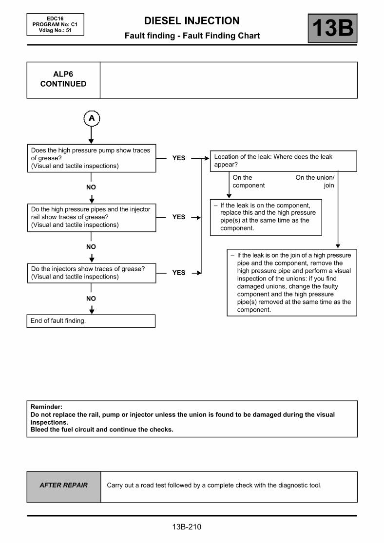
DIESEL INJECTIONFault finding - Fault Finding Chart 13B
13B-210
EDC16PROGRAM No: C1
Vdiag No.: 51
ALP6 CONTINUED
Does the high pressure pump show traces of grease?(Visual and tactile inspections)
YES
NO
Do the high pressure pipes and the injector rail show traces of grease?(Visual and tactile inspections)
YES
NO
Do the injectors show traces of grease?(Visual and tactile inspections)
YES
NO
End of fault finding.
Location of the leak: Where does the leak appear?
On the component
On the union/join
– If the leak is on the component, replace this and the high pressure pipe(s) at the same time as the component.
– If the leak is on the join of a high pressure pipe and the component, remove the high pressure pipe and perform a visual inspection of the unions: if you find damaged unions, change the faulty component and the high pressure pipe(s) removed at the same time as the component.
Reminder:Do not replace the rail, pump or injector unless the union is found to be damaged during the visual inspections.Bleed the fuel circuit and continue the checks.
AFTER REPAIR Carry out a road test followed by a complete check with the diagnostic tool.
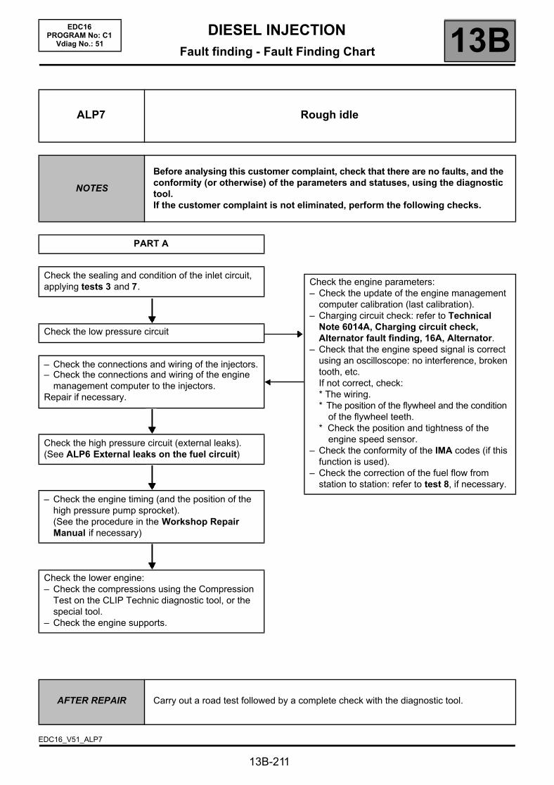
DIESEL INJECTIONFault finding - Fault Finding Chart 13B
13B-211
EDC16PROGRAM No: C1
Vdiag No.: 51
ALP7 Rough idle
NOTES
Before analysing this customer complaint, check that there are no faults, and the conformity (or otherwise) of the parameters and statuses, using the diagnostic tool.If the customer complaint is not eliminated, perform the following checks.
PART A
Check the sealing and condition of the inlet circuit, applying tests 3 and 7.
Check the low pressure circuit
– Check the connections and wiring of the injectors.– Check the connections and wiring of the engine
management computer to the injectors.Repair if necessary.
Check the high pressure circuit (external leaks).(See ALP6 External leaks on the fuel circuit)
– Check the engine timing (and the position of the high pressure pump sprocket).(See the procedure in the Workshop Repair Manual if necessary)
Check the lower engine:– Check the compressions using the Compression
Test on the CLIP Technic diagnostic tool, or the special tool.
– Check the engine supports.
Check the engine parameters:– Check the update of the engine management
computer calibration (last calibration).– Charging circuit check: refer to Technical
Note 6014A, Charging circuit check, Alternator fault finding, 16A, Alternator.
– Check that the engine speed signal is correct using an oscilloscope: no interference, broken tooth, etc.If not correct, check:* The wiring.* The position of the flywheel and the condition
of the flywheel teeth.* Check the position and tightness of the
engine speed sensor.– Check the conformity of the IMA codes (if this
function is used).– Check the correction of the fuel flow from
station to station: refer to test 8, if necessary.
AFTER REPAIR Carry out a road test followed by a complete check with the diagnostic tool.
EDC16_V51_ALP7

DIESEL INJECTIONFault finding - Fault Finding Chart 13B
13B-212
EDC16PROGRAM No: C1
Vdiag No.: 51
ALP8 Oil leaks from the turbocharger
NOTES
Before dealing with this customer complaint, check that there are no faults, and the conformity (or otherwise) of the parameters and statuses using the diagnostic tool.If the customer complaint is not eliminated, perform the following checks.
Clean the oily parts of the turbocharger, when cold, with cleaning cloths (part number: 77 11 211 707).
If the leak is at the inlet or outlet of the turbocharger's oil supply:Replace the seal of the leaky pipe or the pipes if necessary.
If the leak is at the inlet or outlet of the turbine* or of the compressor*:Manually check whether the end float is normal or excessive.Is the end float normal?
NO
YES
If the leak is on the rear plate (compressor housing).Replace the turbocharger.
At idle speed, check if the turbocharger is leaking from the turbocharger oil supply inlet or outlet, from the turbine inlet or outlet or from the compressor and the rear plate of the compressor housing.
Replace the turbocharger and check:– that the turbocharger oil supply circuit is
not blocked.Perform an oil change and change the oil filter.Change the air duct.Empty and clean the intercooler and the air circuit ducts.
IMPORTANTRisk of breaking the new turbocharger and the engine, if the air circuit is not cleaned and the oil and its filter are not replaced.
AFTER REPAIR Carry out a road test followed by a complete check with the diagnostic tool.
EDC16_V51_ALP8

DIESEL INJECTIONFault finding - Fault Finding Chart 13B
13B-213
EDC16PROGRAM No: C1
Vdiag No.: 51
ALP8CONTINUED
* Note: It is normal to find traces of oil at the turbocharger inlet and outlet, as the air passing through the compressor is loaded with oil from the engine rebreathing circuit.
The operating play of the turbocharger bearings is approximately 25 µm between the shaft of the turbocharger and the internal mating face of the bearings and 75 µm between the exterior part of the bearings and the housing of the bearings.Risks:In the event of destruction of the turbocharger bearings, the steel and bronze swarf from this destruction are evacuated through the turbocharger oil to the engine's oil sump. The swarf can, consequently, be returned to the oil circuit via the oil pump, then cause widespread pollution of the engine oil circuit. This causes abnormal wear on the crankshaft bearing bushings, the con rod bearing shells and the camshafts, etc.In the event of the compressor wheel breaking, parts of the blades may be found in the intercooler or in the air circuit ducts. The turbine wheel could easily be found in the catalytic converter.
AFTER REPAIR Carry out a road test followed by a complete check with the diagnostic tool.

DIESEL INJECTIONFault finding - Test 13B
13B-214
EDC16PROGRAM No: C1
Vdiag No.: 51Fault finding - Test
EXHAUST SYSTEM CHECK TEST1
LOW PRESSURE CIRCUIT CHECK TEST2
TURBOCHARGED AIR INLET CIRCUIT CHECK TEST3
AIR FLOW SENSOR TEST4
COMMAND FOR A VARIABLE GEOMETRY TURBOCHARGER TEST5
ROTATING SECTION OF A TURBOCHARGER TEST6
EXHAUST GAS RECIRCULATION VALVE TEST7
POOR INJECTOR OPERATION TEST8

DIESEL INJECTIONFault finding - Test 13B
13B-215
EDC16PROGRAM No: C1
Vdiag No.: 51
TEST1 Exhaust system check
Engine stopped: Check that the silencer outlet is not blocked. Repair or replace the silencer, if necessary.
Check the seal of the exhaust manifold on the contact surface between the turbocharger and the exhaust manifold.Is the seal in order?
YES
Loosen the catalytic pre-converter on the turbocharger side. Place a wooden block between the two parts.Start the vehicle and check if the engine runs better.Is the engine running normally?
YES
NO Repair or replace the faulty part.
NOThe exhaust pipe is not the cause of the fault. Continue with the engine fault finding (see ALP5).
EDC16_V51_TEST1

DIESEL INJECTIONFault finding - Test 13B
13B-216
EDC16PROGRAM No: C1
Vdiag No.: 51
TEST1CONTINUED
Retighten the catalytic pre-converter.Loosen the catalytic converter on the catalytic pre-converter side. Place a wooden block between the two parts.Start the vehicle and check if the engine runs better.Is the engine running normally?
YES
Retighten the catalytic converter.Loosen or disconnect the intermediate chamber on the catalytic converter side. Insert a wooden block between the two parts, if necessary.Start the vehicle and check if the engine runs better.Is the engine running normally?
YES
Re-tighten the intermediate chamber.Loosen or disconnect the silencer on the intermediate chamber side. Insert a wooden block between the two parts, if necessary.Start the vehicle and check if the engine runs better.Is the engine running normally?
YES
Replace the silencer.END OF TEST1.
NO Replace the catalytic pre-converter.
NO Replace the catalytic converter.
NO Replace the intermediate chamber.
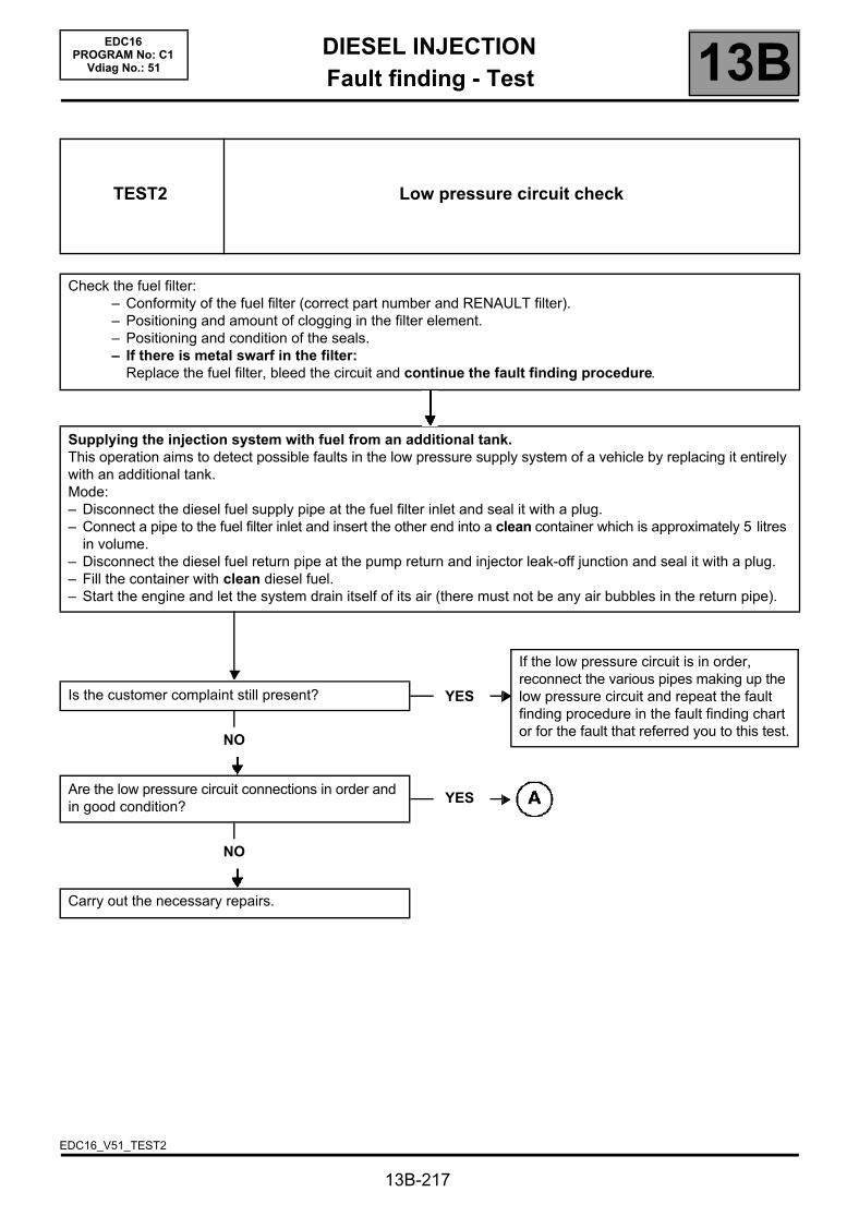
DIESEL INJECTIONFault finding - Test 13B
13B-217
EDC16PROGRAM No: C1
Vdiag No.: 51
TEST2 Low pressure circuit check
Check the fuel filter:– Conformity of the fuel filter (correct part number and RENAULT filter).– Positioning and amount of clogging in the filter element.– Positioning and condition of the seals.– If there is metal swarf in the filter:
Replace the fuel filter, bleed the circuit and continue the fault finding procedure.
Supplying the injection system with fuel from an additional tank.This operation aims to detect possible faults in the low pressure supply system of a vehicle by replacing it entirely with an additional tank.Mode:– Disconnect the diesel fuel supply pipe at the fuel filter inlet and seal it with a plug.– Connect a pipe to the fuel filter inlet and insert the other end into a clean container which is approximately 5 litres
in volume.– Disconnect the diesel fuel return pipe at the pump return and injector leak-off junction and seal it with a plug.– Fill the container with clean diesel fuel.– Start the engine and let the system drain itself of its air (there must not be any air bubbles in the return pipe).
Is the customer complaint still present?
NO
Are the low pressure circuit connections in order and in good condition?
NO
Carry out the necessary repairs.
YES
If the low pressure circuit is in order, reconnect the various pipes making up the low pressure circuit and repeat the fault finding procedure in the fault finding chart or for the fault that referred you to this test.
YES
EDC16_V51_TEST2
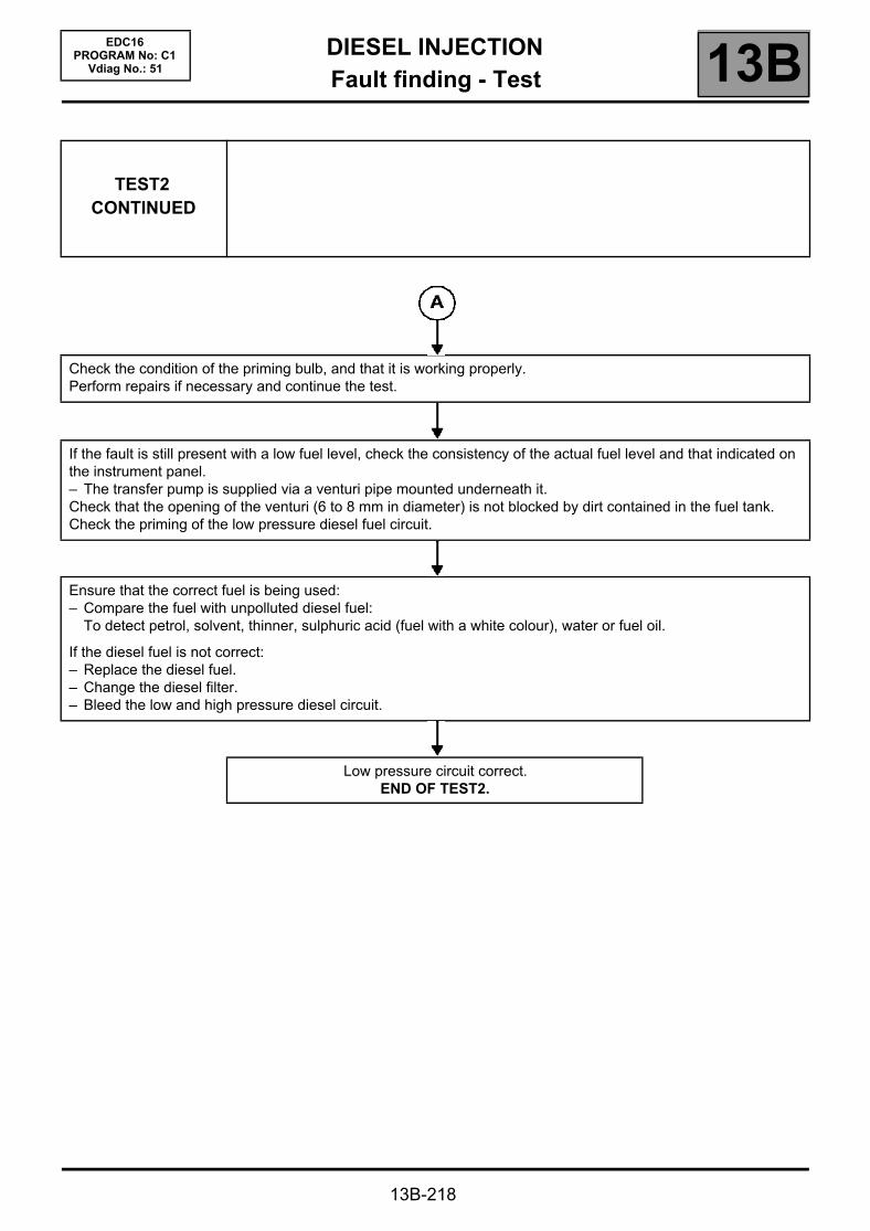
DIESEL INJECTIONFault finding - Test 13B
13B-218
EDC16PROGRAM No: C1
Vdiag No.: 51
TEST2CONTINUED
Check the condition of the priming bulb, and that it is working properly.Perform repairs if necessary and continue the test.
If the fault is still present with a low fuel level, check the consistency of the actual fuel level and that indicated on the instrument panel.– The transfer pump is supplied via a venturi pipe mounted underneath it.Check that the opening of the venturi (6 to 8 mm in diameter) is not blocked by dirt contained in the fuel tank.Check the priming of the low pressure diesel fuel circuit.
Ensure that the correct fuel is being used:– Compare the fuel with unpolluted diesel fuel:
To detect petrol, solvent, thinner, sulphuric acid (fuel with a white colour), water or fuel oil.
If the diesel fuel is not correct:– Replace the diesel fuel.– Change the diesel filter.– Bleed the low and high pressure diesel circuit.
Low pressure circuit correct.END OF TEST2.
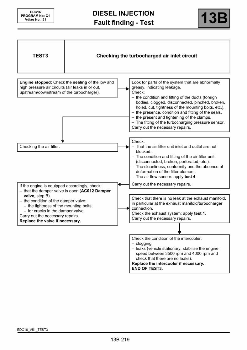
DIESEL INJECTIONFault finding - Test 13B
Checking the air filter.
If the engine is equipped accordingly, check:– that the damper valve is open (AC012 Damper
valve, step B).– the condition of the damper valve:
– the tightness of the mounting bolts,– for cracks in the damper valve.
Carry out the necessary repairs.Replace the valve if necessary.
13B-219
EDC16PROGRAM No: C1
Vdiag No.: 51
TEST3 Checking the turbocharged air inlet circuit
Engine stopped: Check the sealing of the low and high pressure air circuits (air leaks in or out, upstream/downstream of the turbocharger).
Look for parts of the system that are abnormally greasy, indicating leakage.Check:– the condition and fitting of the ducts (foreign
bodies, clogged, disconnected, pinched, broken, holed, cut, tightness of the mounting bolts, etc.).
– the presence, condition and fitting of the seals.– the present and tightening of the clamps.– The fitting of the turbocharging pressure sensor.Carry out the necessary repairs.
Check:– That the air filter unit inlet and outlet are not
blocked.– The condition and fitting of the air filter unit
(disconnected, broken, perforated, etc.).– The cleanliness, conformity and the absence of
deformation of the filter element.– The air flow sensor: apply test 4.
Carry out the necessary repairs.
Check that there is no leak at the exhaust manifold, in particular at the exhaust manifold/turbocharger connection.Check the exhaust system: apply test 1.Carry out the necessary repairs.
Check the condition of the intercooler:– clogging,– leaks (vehicle stationary, stabilise the engine
speed between 3500 rpm and 4000 rpm and check that there are no leaks).
Replace the intercooler if necessary.END OF TEST3.
EDC16_V51_TEST3

DIESEL INJECTIONFault finding - Test 13B
13B-220
EDC16PROGRAM No: C1
Vdiag No.: 51
* OCR: Opening Cyclic Ratio.
TEST4 Air flow sensor
POLLUTION OF THE GRILLES:Visual inspection: remove the flow sensor. There should be no foreign bodies in the grilles (see illustration on the next page).Do not clean the grilles using compressed air or any other procedure: this damages the sensors and creates variations from the values displayed on the CLIP tool.Check the sealing of the air circuit upstream of the air flow sensor:disconnected or pierced pipes and air filter unit, seals present.Replace the air flow sensor if necessary and clean upstream of this, if necessary.
ELECTRICAL COMPONENT BREAKAGE:Visual inspection:remove the flow sensor: the components must not be broken (see picture on following page).Replace the air flow sensor if necessary.
OXIDATION OF THE ELECTRICAL COMPONENTS:Visual inspection:dismantle the air flow sensor, there should not be any green deposits on the electrical components.Replace the air flow sensor if necessary.
CLOGGING OF THE AIR FLOW SENSOR:Test:– Check the values for conformity:
* During the first 5 seconds after starting:– Coolant temperature: 80 °C,– Engine speed: idle speed (800 ± 50 rpm);– Measure the air flow: 47 kg/h ± 10.– OCR* EGR valve: between - 10 % and 0 %.
* After the starting phase:– Coolant temperature: 80 °C,– Engine speed: idle speed (800 ± 50 rpm);– Air flow measurement: 30 kg/h ± 5 %;– OCR* EGR valve: between 10 % and 40 %.
– Refer to DF056 Air flow sensor circuit 2.def, for the air flow sensor checks.Replace the air flow sensor if necessary.
EDC16_V51_TEST4
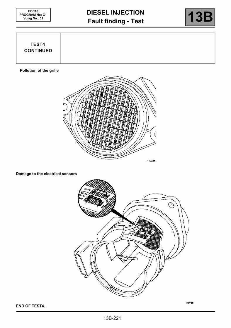
DIESEL INJECTIONFault finding - Test 13B
13B-221
EDC16PROGRAM No: C1
Vdiag No.: 51
Pollution of the grille
Damage to the electrical sensors
TEST4CONTINUED
END OF TEST4.

DIESEL INJECTIONFault finding - Test 13B
13B-222
EDC16PROGRAM No: C1
Vdiag No.: 51
TEST5 Variable geometry turbocharger control
Engine stopped:Check manually if the variable geometry control rod is jammed.Is the rod jammed?
NO
At idle speed, with turbocharging solenoid valve control: between 70 % and 85 % OCR*, disconnect the electrical connector of the solenoid valve and check at the same time if the rod controlling the variable geometry blades moves.Does the rod move from end to end?
NO
Check the condition of the turbocharging valve connectors (oxidation, bent pin, etc.).Measure the resistance of the turbocharging solenoid valve between its tracks 1 and 2. It should be:15.4 ΩΩΩΩ ±±±± 0.7 at + 20 °°°°C for a Pierburg solenoid valve.Is the solenoid valve in order?
NO
Replace the turbocharging solenoid valve.
YES
– Replace the turbocharger.– Perform a visual inspection of the
condition of the turbine and the compressor (see the illustrations of test 6).
If one of the 2 wheels is damaged, you should also replace the duct connected to the damaged wheel.
YESThe turbocharging control circuit is operating normally.
YES
Check the continuity and insulation to + 12 V and to earth of the connection between track E1 of connector C of the engine management computer and track 1 of the turbocharger solenoid valve connector.Check the continuity and insulation to earth of the connection between the UPC PPM1 connector track 1 and track 2 of the turbocharger solenoid valve connector.If necessary, carry out repairs.
EDC16_V51_TEST5

DIESEL INJECTIONFault finding - Test 13B
13B-223
EDC16PROGRAM No: C1
Vdiag No.: 51
TEST5CONTINUED
Reconnect the electrical connector of the turbocharging solenoid valve.On the control diaphragm of the variable geometry blades, disconnect the pipe coming from the solenoid valve. Connect a pressure gauge in place of the diaphragm. Engine at idle speed.Check that there is a vacuum at the pipe outlet?
NO
Measure the vacuum pressure upstream of the turbocharging solenoid valve.
Is the vacuum pressure > 750 mbar?
NO
Check the vacuum circuit and repeat the test for the vacuum pressure check.
YES Is the vacuum pressure > 750 mbar?
NO YES
Replace the turbocharger.
YES Replace the turbocharging solenoid valve.
END OF TEST5.
* OCR: Opening Cyclic Ratio.
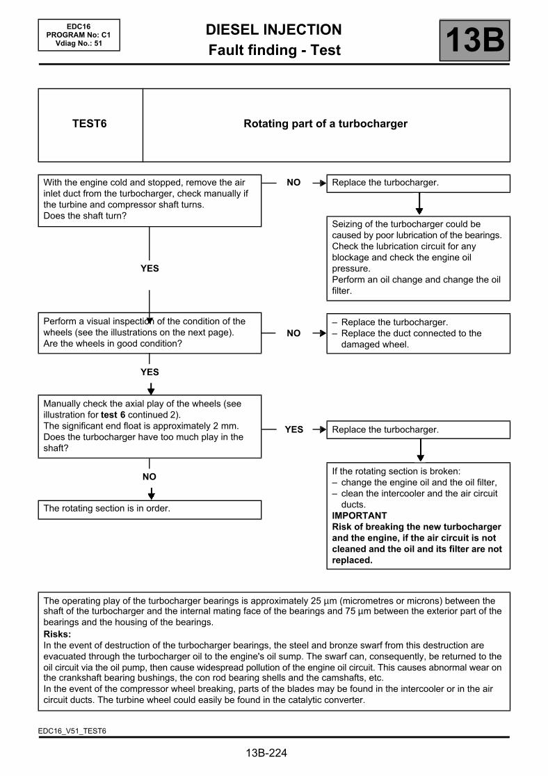
DIESEL INJECTIONFault finding - Test 13B
13B-224
EDC16PROGRAM No: C1
Vdiag No.: 51
TEST6 Rotating part of a turbocharger
With the engine cold and stopped, remove the air inlet duct from the turbocharger, check manually if the turbine and compressor shaft turns.Does the shaft turn?
YES
Perform a visual inspection of the condition of the wheels (see the illustrations on the next page).Are the wheels in good condition?
YES
Manually check the axial play of the wheels (see illustration for test 6 continued 2).The significant end float is approximately 2 mm.Does the turbocharger have too much play in the shaft?
NO
The rotating section is in order.
NO Replace the turbocharger.
Seizing of the turbocharger could be caused by poor lubrication of the bearings. Check the lubrication circuit for any blockage and check the engine oil pressure.Perform an oil change and change the oil filter.
NO– Replace the turbocharger.– Replace the duct connected to the
damaged wheel.
YES Replace the turbocharger.
If the rotating section is broken:– change the engine oil and the oil filter,– clean the intercooler and the air circuit
ducts.IMPORTANTRisk of breaking the new turbocharger and the engine, if the air circuit is not cleaned and the oil and its filter are not replaced.
The operating play of the turbocharger bearings is approximately 25 µm (micrometres or microns) between the shaft of the turbocharger and the internal mating face of the bearings and 75 µm between the exterior part of the bearings and the housing of the bearings.Risks:In the event of destruction of the turbocharger bearings, the steel and bronze swarf from this destruction are evacuated through the turbocharger oil to the engine's oil sump. The swarf can, consequently, be returned to the oil circuit via the oil pump, then cause widespread pollution of the engine oil circuit. This causes abnormal wear on the crankshaft bearing bushings, the con rod bearing shells and the camshafts, etc.In the event of the compressor wheel breaking, parts of the blades may be found in the intercooler or in the air circuit ducts. The turbine wheel could easily be found in the catalytic converter.
EDC16_V51_TEST6

DIESEL INJECTIONFault finding - Test 13B
13B-225
EDC16PROGRAM No: C1
Vdiag No.: 51
Deformed, twisted blade ("soft" foreign body)
Broken blades ("hard" foreign body)
TEST6CONTINUED 1

DIESEL INJECTIONFault finding - Test 13B
13B-226
EDC16PROGRAM No: C1
Vdiag No.: 51
1 End float2 Radial play
TEST6CONTINUED 2
END OF TEST6.

DIESEL INJECTIONFault finding - Test 13B
13B-227
EDC16PROGRAM No: C1
Vdiag No.: 51
TEST7 Exhaust gas recirculation valve
PART A
VALVE POSITION FAULT FINDING:Or detection of a leak on the exhaust gas recirculation valvePlease observe the cleanliness guidelines and safety advice.Clear the faults.Run command SC036 Reinitialisation of programming and select EGR valve to reinitialise the EGR valve offsets (see Replacement of components").Switch off the ignition and wait for 1 minute.Switch the ignition back on and check for faults.
If the fault is still present:– exit CLIP tool diagnostic mode,– switch off the vehicle ignition,– disconnect the exhaust gas recirculation valve connector,– remove the exhaust gas recirculation valve using the special tool and reconnect it after having removed it,– check that no particles are blocking the movement of the exhaust gas recirculation valve flap,– check that the exhaust gas recirculation valve is not stuck or jammed in one position,– switch on the ignition again and return to fault finding mode using the CLIP tool,– check the movement of the valve with PR005 EGR valve OCR* (0 to 2.5 mm travel for an opening cyclic ratio
of 40 % and when fully open, ~ 5 mm, for an Opening Cyclic Ratio of 95 %),– check that the exhaust gas recirculation valve flap closes completely,– if there has been no movement, or if the exhaust gas recirculation valve is completely seized, replace the exhaust
gas recirculation valve and follow the procedure for replacing the exhaust gas recirculation valve (see Replacement of components).
EDC16_V51_TEST7
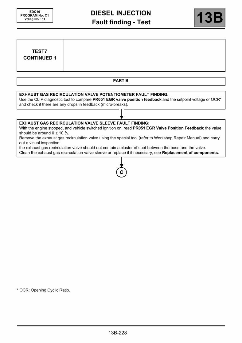
DIESEL INJECTIONFault finding - Test 13B
13B-228
EDC16PROGRAM No: C1
Vdiag No.: 51
TEST7CONTINUED 1
PART B
EXHAUST GAS RECIRCULATION VALVE POTENTIOMETER FAULT FINDING:Use the CLIP diagnostic tool to compare PR051 EGR valve position feedback and the setpoint voltage or OCR* and check if there are any drops in feedback (micro-breaks).
EXHAUST GAS RECIRCULATION VALVE SLEEVE FAULT FINDING:With the engine stopped, and vehicle switched ignition on, read PR051 EGR Valve Position Feedback; the value should be around 0 ± 10 %.Remove the exhaust gas recirculation valve using the special tool (refer to Workshop Repair Manual) and carry out a visual inspection:the exhaust gas recirculation valve should not contain a cluster of soot between the base and the valve.Clean the exhaust gas recirculation valve sleeve or replace it if necessary, see Replacement of components.
* OCR: Opening Cyclic Ratio.
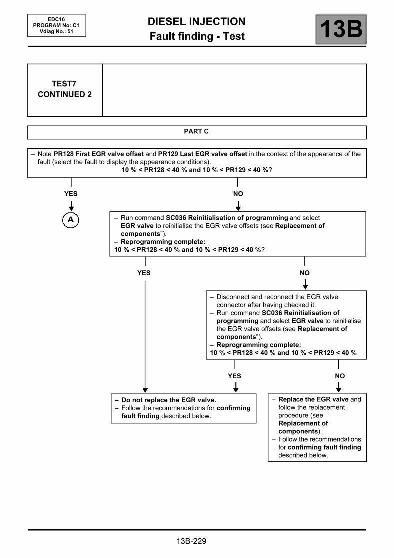
DIESEL INJECTIONFault finding - Test 13B
TEST7CONTINUED 2
PART C
– Note PR128 First EGR valve offset and PR129 Last EGR valve offset in the context of the appearance of the fault (select the fault to display the appearance conditions).
10 % < PR128 < 40 % and 10 % < PR129 < 40 %?
YES NO
– Run command SC036 Reinitialisation of programming and select EGR valve to reinitialise the EGR valve offsets (see Replacement of components").
– Reprogramming complete:10 % < PR128 < 40 % and 10 % < PR129 < 40 %?
YES NO
– Do not replace the EGR valve.– Follow the recommendations for confirming
fault finding described below.
13B-229
EDC16PROGRAM No: C1
Vdiag No.: 51
– Disconnect and reconnect the EGR valve connector after having checked it.
– Run command SC036 Reinitialisation of programming and select EGR valve to reinitialise the EGR valve offsets (see Replacement of components").
– Reprogramming complete:10 % < PR128 < 40 % and 10 % < PR129 < 40 %
YES NO
– Replace the EGR valve and follow the replacement procedure (see Replacement of components).
– Follow the recommendations for confirming fault finding described below.
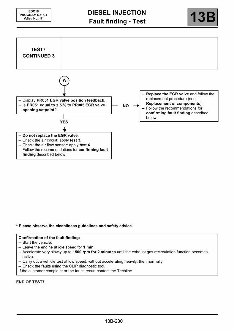
DIESEL INJECTIONFault finding - Test 13B
13B-230
EDC16PROGRAM No: C1
Vdiag No.: 51
TEST7CONTINUED 3
– Display PR051 EGR valve position feedback.– Is PR051 equal to ±±±± 5 % to PR005 EGR valve
opening setpoint?
YES
– Do not replace the EGR valve.– Check the air circuit: apply test 3.– Check the air flow sensor: apply test 4.– Follow the recommendations for confirming fault
finding described below.
NO
– Replace the EGR valve and follow the replacement procedure (see Replacement of components).
– Follow the recommendations for confirming fault finding described below.
* Please observe the cleanliness guidelines and safety advice.
END OF TEST7.
Confirmation of the fault finding:– Start the vehicle.– Leave the engine at idle speed for 1 min.– Accelerate very slowly up to 1500 rpm for 2 minutes until the exhaust gas recirculation function becomes
active.– Carry out a vehicle test at low speed, without accelerating heavily, then normally.– Check the faults using the CLIP diagnostic tool.If the customer complaint or the faults recur, contact the Techline.

DIESEL INJECTIONFault finding - Test 13B
13B-231
EDC16PROGRAM No: C1
Vdiag No.: 51
TEST8 Poor injector operation
Part A
Fuel regulation balance check for each injector: (individual correction)
– In CLIP, select the Fuel circuit sub-function.– With the engine idling and the fuel temperature > 50 °°°°C, view the flow correction values of each injector
(individual correction), i.e.:
PR364 Cylinder no. 1 fuel flow correction;PR405 Cylinder no. 2 fuel flow correction;PR406 Cylinder no. 3 fuel flow correction;PR365 Cylinder no. 4 fuel flow correction.
The normal injector flow correction value is approximately ±±±± 1 mg/stroke.This tolerance may increase with time,but indicates an injector/cylinder fault if it exceeds ±±±± 5 mg/st.
1) If at least one of these values is > + 5 mg/st– Check the valve clearance.– Check the condition of the engine and test the compressions.– If the compression test reveals a cylinder fault, carry out the necessary repairs.– If the compression is correct, check that the injector is fitted correctly by following the procedure (see MR 364
Mechanics, 13B, Diesel injection: Removal - Refitting) then check the fuel regulation for each injector again (check each injector individually).
– If the customer complaint is still present, replace the injector*.– See paragraph Part B, for the confirmation of the fault finding.
2) If at least one of these values is < - 5 mg/st– Check the valve clearance.– Check the level and condition of the engine oil.– Remove the injector with the greatest correction.– If there is pollution from the diesel, check the condition of the cylinder concerned (cylinder, piston, valves).– Replace the injector.– See Section B, to confirm the fault finding.
3) If at least one of these values does not stabilise (20 seconds after starting)– Check the low pressure circuit with test 3: Low pressure circuit check.– Compare the fuel with some clean diesel in order to detect petrol, solvent, thinners, sulphuric acid (fuel will have
a whitish appearance), water or fuel oil.– See Section B, to confirm the fault finding.
After replacing an injector, follow the injector code programming procedure (refer to Replacement of components ), run SC036 Reset programming and select the number of the injector replaced.
IMPORTANTWhen removing and refitting the injectors, follow the cleanliness guidelines and safety advice (see MR 364 Mechanics, 13B, Diesel injection: Removal - Refitting).
EDC16_V51_TEST8

DIESEL INJECTIONFault finding - Test 13B
13B-232
EDC16PROGRAM No: C1
Vdiag No.: 51
TEST8CONTINUED
Part B
Confirmation of flow correction fault finding for each injector: (individual correction)
Clear the fault(s) and carry out a test with the engine at idle speed and the fuel temperature at > 50 °°°°C. To check the repair, see that no faults appear on the diagnostic tool and that the correction values do not reach ± 5 mg/stroke.– If any other cylinders have injector flow correction values which exceed ±±±± 5 mg/stroke, follow the fault finding
procedure described in Part A. Fuel regulation balance check for each injector (individual).– If any other cylinders have injector flow correction values which do not exceed ±±±± 5 mg/stroke, follow the fault
finding procedure detailed in Part C.
Part C
Injector nozzle sealing test:– Check the level and condition of the engine oil:– If there is pollution from the diesel oil, the injector nozzle which is leaking will be greasy.– Disconnect the preheating relay.– Check that this is not caused by rising engine oil by checking the engine compression values.– Check the condition of the heater plug: this must not be wet. If it is, change the defective injector.– If the engine compression values are correct, locate the faulty injector by looking at the condition of the cylinders
and the pistons through the heater plug holes (greasy cylinder, overheating, signs of damage, etc.).– If the cylinder - piston examination is not conclusive, remove the injectors and change the one with the greasy
nozzle.– If the fault finding checks do not enable the engine to be repaired, contact the Techline.
*Note:Before replacing an injector, check the presence and conformity of its sealing washer (refer to ALP 4, Poor performance).
IMPORTANTWhen removing and refitting the injectors, follow the cleanliness guidelines and safety advice (see MR 364 Mechanics, 13B, Diesel injection: Removal - Refitting).
END OF TEST8.

DIESEL INJECTIONFault finding - Glossary 13B
13B-233
EDC16PROGRAM No: C1
Vdiag No.: 51Fault finding - Glossary
(R = Resistance, EGR = Exhaust gas recirculation, FAP = Particle filter)
Injection computer112-track (BOSCH)Connectors: black A 32-track, brown B 48-track, grey C 32-track
Atmospheric pressure sensor Integrated into the computer (BOSCH)
Injector0.23 Ω at + 20 °C/2 Ω max (BOSCH)1,600 bar (1,800 bar max.)
Flow regulator (high pressure pump)
R = 3 Ω at + 20 °C (BOSCH, pump type CP3.2+)
Rail pressure sensorStart of opening ~ 1,600 bar,Pressure limiter on the CP3 pump: maximum flow at 1800 bar(BOSCH, bolted to the rail)
Engine speed sensor R = 800 ± 80 Ω at + 20 °C (MGI)
Camshaft sensorHall effect sensor (ELECTRICFIL)R = 10250 ± 500 Ω at + 20 °C (measured between tracks 2 and 3 of the sensor)
Turbocharger control solenoid valve 15.4 ± 0.7 Ω at + 20 °C (PIERBURG)
Electric EGR valve
Track 1: + 12 V electric motorTrack 2: + 5 V potentiometerTrack 3: Not used
Track 4: potentiometer earthTrack 5: engine earthTrack 6: potentiometer signal
DIRECT CURRENT MOTOR: R between tracks 1 and 5 = 2.96 ± 0.3 Ω at + 20 °CPOTENTIOMETER: R between its tracks 2 and 4: 6.5 ± 0.6 kΩ at + 20 °C(SIEMENS)
Electric damper valve MOTOR (VDO)
Air flow sensor
Track 1: air temperature signal Track 2: flow sensor earthTrack 3: + 5 V flow sensor
Track 4: + 12 V battery feedTrack 5: air flow signalTrack 6: battery earth
(SIEMENS)
Air temperature sensor R = 3714 Ω ± 161 at + 10 °C/2448 Ω ± 96 at + 20 °C/1671 Ω ± 59 at + 30 °C
Coolant temperature sensor R = 2252 Ω ± 112 at 25 °C/811 Ω ± 39 at 50 °C/283 Ω ± 8 at 80 °C
Accelerator pedal sensorR gang 1 = 1700 ± 900 Ω;R gang 2 = 2,850 ± 2,050 Ω
Heater plugR = 0.6 Ω at + 20 °C/2 Ω maximumMaximum current drawn: 28 A at 0 seconds/12 A at 10 seconds/9 A after 30 seconds
Presence of water in diesel sensor According to application (ZERTAN)