Embed Size (px)
Citation preview
1
1
2
2
3
3
4
4
5
5
6
6
D D
C C
B B
A A
1 15
1/5/2018
ADAS_SF_rev1_CoverSheet.SchDoc
Sheet Title:
Size:
Mod. Date:
File:Sheet: of
B http://www.ti.comContact: http://www.ti.com/support
ADAS Sensor Fusion BoardProject Title:Designed for: Public Release
Assembly Variant: Populated_variant
© Texas Instruments 2017Drawn By:Engineer: Spectrum Digital
Texas Instruments and/or its licensors do not warrant the accuracy or completeness of this specification or any information contained therein. Texas Instruments and/or its licensors do not warrant that this design will meet the specifications, will be suitable for your application or fit for any particular purpose, or will operate in an implementation. Texas Instruments and/or its licensors do not warrant that the design is production worthy. You should completely validate and test your design implementation to confirm the system functionality for your application.
Not in version controlSVN Rev:518520BNumber: Rev: E3
TID #: N/AOrderable: EVM_orderable
Revision HistoryRev NotesApproved byECN # Approved Date
B/E3 N/A 01/05/2018 JAC N/A
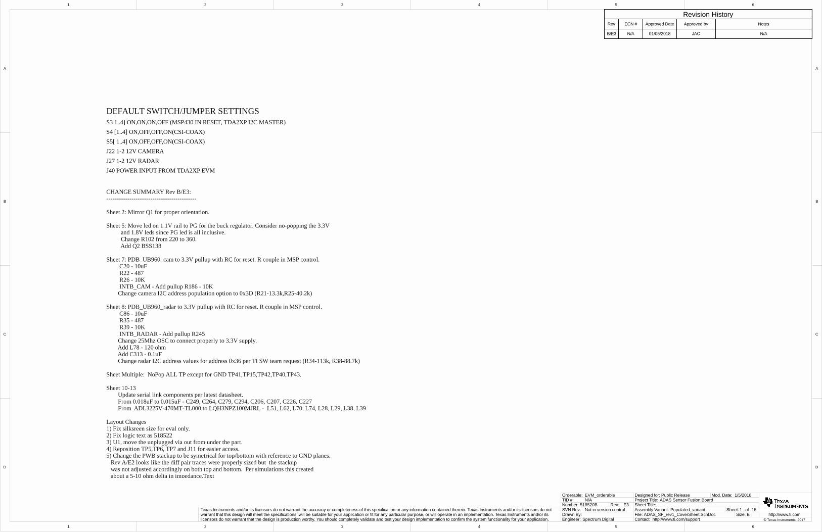
S4 [1..4] ON,OFF,OFF,ON(CSI-COAX)S5[ 1..4] ON,OFF,OFF,ON(CSI-COAX)J22 1-2 12V CAMERAJ27 1-2 12V RADAR
S3 1..4] ON,ON,ON,OFF (MSP430 IN RESET, TDA2XP I2C MASTER)
DEFAULT SWITCH/JUMPER SETTINGS
J40 POWER INPUT FROM TDA2XP EVM
CHANGE SUMMARY Rev B/E3:-------------------------------------------
Sheet 2: Mirror Q1 for proper orientation.
Sheet 5: Move led on 1.1V rail to PG for the buck regulator. Consider no-popping the 3.3V and 1.8V leds since PG led is all inclusive. Change R102 from 220 to 360. Add Q2 BSS138
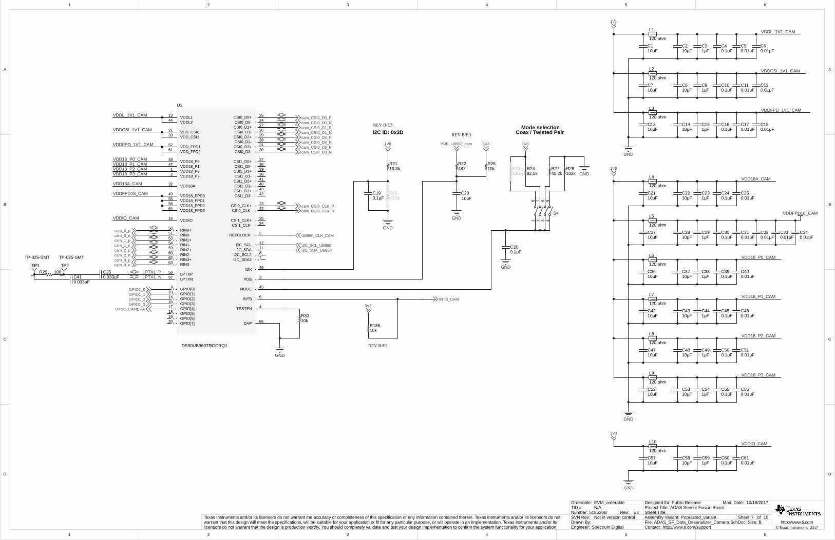
Sheet 7: PDB_UB960_cam to 3.3V pullup with RC for reset. R couple in MSP control. C20 - 10uF R22 - 487 R26 - 10K INTB_CAM - Add pullup R186 - 10K Change camera I2C address population option to 0x3D (R21-13.3k,R25-40.2k)
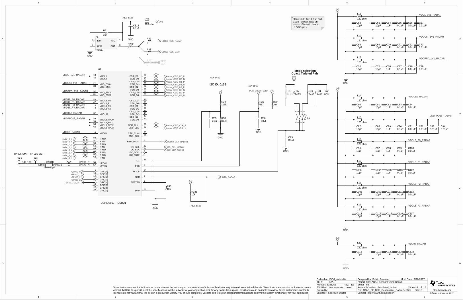
Sheet 8: PDB_UB960_radar to 3.3V pullup with RC for reset. R couple in MSP control. C86 - 10uF R35 - 487 R39 - 10K INTB_RADAR - Add pullup R245 Change 25Mhz OSC to connect properly to 3.3V supply. Add L78 - 120 ohm Add C313 - 0.1uF Change radar I2C address values for address 0x36 per TI SW team request (R34-113k, R38-88.7k)
Sheet Multiple: NoPop ALL TP except for GND TP41,TP15,TP42,TP40,TP43.
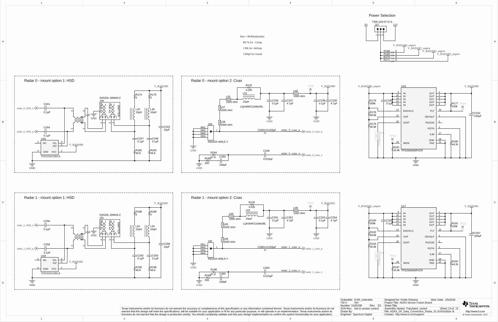
Sheet 10-13 Update serial link components per latest datasheet. From 0.018uF to 0.015uF - C249, C264, C279, C294, C206, C207, C226, C227 From ADL3225V-470MT-TL000 to LQH3NPZ100MJRL - L51, L62, L70, L74, L28, L29, L38, L39
Layout Changes1) Fix silksreen size for eval only.2) Fix logic text as 5185223) U1, move the unplugged via out from under the part.4) Reposition TP5,TP6, TP7 and J11 for easier access.5) Change the PWB stackup to be symetrical for top/bottom with reference to GND planes. Rev A/E2 looks like the diff pair traces were properly sized but the stackup was not adjusted accordingly on both top and bottom. Per simulations this created about a 5-10 ohm delta in impedance.Text

1
1
2
2
3
3
4
4
5
5
6
6
D D
C C
B B
A A
2 15
6/15/2017
ADAS_SF_Power_Battery_Input.SchDoc
Sheet Title:
Size:
Mod. Date:
File:Sheet: of
B http://www.ti.comContact: http://www.ti.com/support
ADAS Sensor Fusion BoardProject Title:Designed for: Public Release
Assembly Variant: Populated_variant
© Texas Instruments 2017Drawn By:Engineer: Spectrum Digital
Texas Instruments and/or its licensors do not warrant the accuracy or completeness of this specification or any information contained therein. Texas Instruments and/or its licensors do not warrant that this design will meet the specifications, will be suitable for your application or fit for any particular purpose, or will operate in an implementation. Texas Instruments and/or its licensors do not warrant that the design is production worthy. You should completely validate and test your design implementation to confirm the system functionality for your application.
Not in version controlSVN Rev:518520BNumber: Rev: E3
TID #: N/AOrderable: EVM_orderable
Car Battery InputVin = 4V - 60V
VCAPL1
GATE PULL DOWN 2
NC 3
ANODE4
NC 5
GATE DRIVE 6
VCAPH7
CATHODE 8
U7
LM74610QDGKRQ1
14V
D2SMBJ14A-13-F
28V
D1SMBJ28A-13-F
1
3 4
Q1
IPD90N04S304ATMA1
100pFC132
2.2µFC137
V_bat
GND
1 2
J13 TSW-102-07-G-S
1 2
J12 TSW-102-07-G-S
4.7µFC135
1µFC133
4.7µFC136
4.7µFC134
GND
4.7µFC130
4.7µFC131
Vin_protect
Vin_protect
TP40GND
GND
TP42GND
GND
TP43GND
GND
TP41GND
GND
TP44GND
GND
TP45
V_bat
TP51Vin_protect
TP52GND
GND
TP53GND
GND
TP54GND
GND
V_bat
12
J14
17572420.01
R1730.01
R172
REV B/E3
1
1
2
2
3
3
4
4
5
5
6
6
D D
C C
B B
A A
3 15
8/25/2017
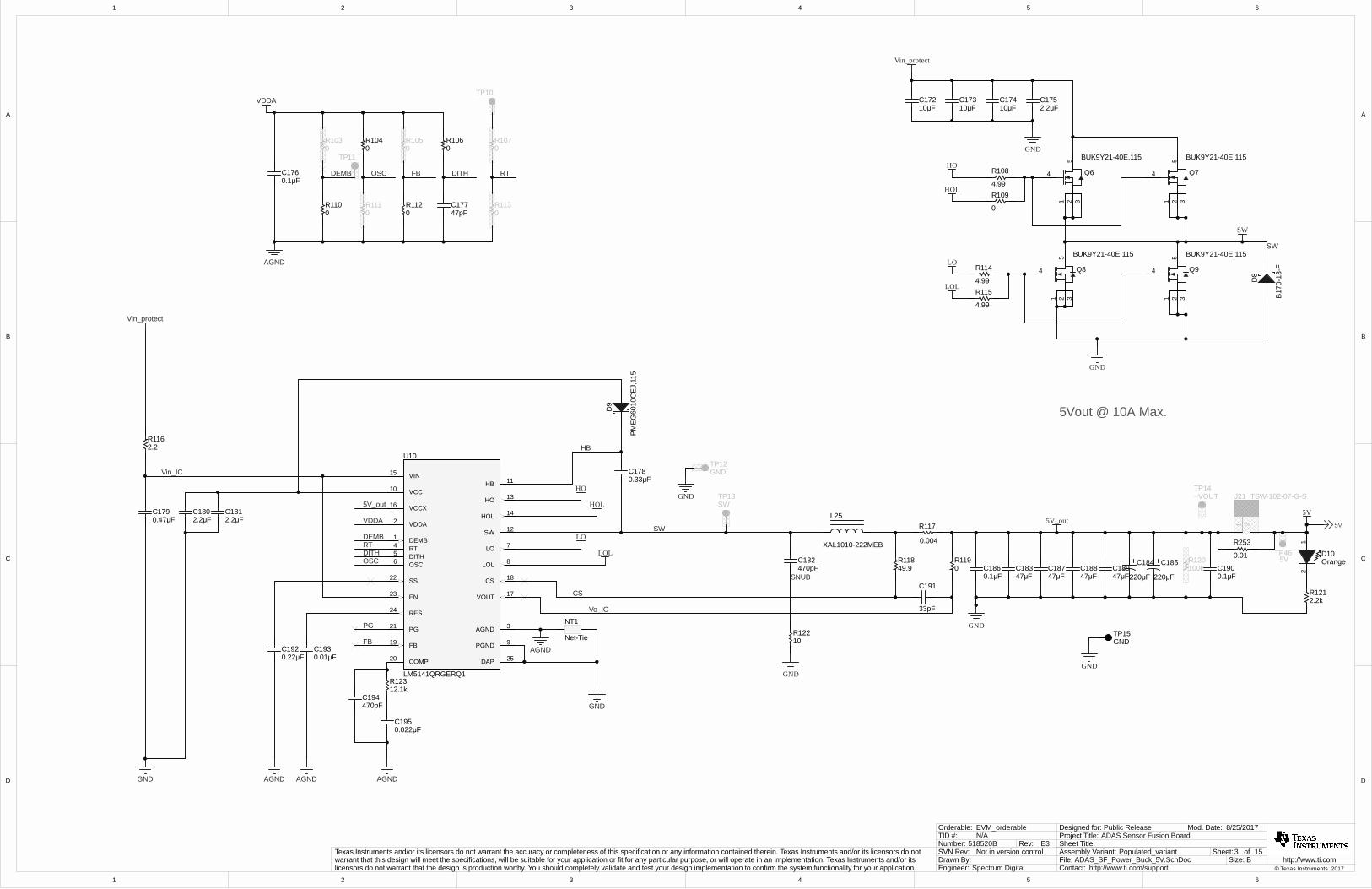
ADAS_SF_Power_Buck_5V.SchDoc
Sheet Title:
Size:
Mod. Date:
File:Sheet: of
B http://www.ti.comContact: http://www.ti.com/support
ADAS Sensor Fusion BoardProject Title:Designed for: Public Release
Assembly Variant: Populated_variant
© Texas Instruments 2017Drawn By:Engineer: Spectrum Digital
Texas Instruments and/or its licensors do not warrant the accuracy or completeness of this specification or any information contained therein. Texas Instruments and/or its licensors do not warrant that this design will meet the specifications, will be suitable for your application or fit for any particular purpose, or will operate in an implementation. Texas Instruments and/or its licensors do not warrant that the design is production worthy. You should completely validate and test your design implementation to confirm the system functionality for your application.
Not in version controlSVN Rev:518520BNumber: Rev: E3
TID #: N/AOrderable: EVM_orderable
Vin_protect
DEMB1
VDDA2
AGND 3
RT4
DITH5
OSC6
LO 7
LOL 8
PGND 9
VCC10HB 11
SW 12
HO 13
HOL 14
VIN15
VCCX16
VOUT 17
CS 18
FB19
COMP20
PG21
SS22
EN23
RES24
DAP 25
U10
LM5141QRGERQ1
0R110
PG
0R111
0R104
0R103
DEMB
OSC
FB
0R112
0R105
FBDEMB OSC
RT
0R113
0R107
RT
VDDA
GND
0.1µFC176
DITH
47pFC177
0R106
DITH
TP11
4.99
R108
0
R109
4.99
R114
4.99
R115
D8
B17
0-13
-F
C1752.2µF
LO
LOL
HO
HOL
SW
GND
GND
10µFC172
10µFC173
10µFC174
SW
Vin_protect
5
4
1 2 3
Q8
BUK9Y21-40E,115 5
4
1 2 3
Q9
BUK9Y21-40E,115
5
4
1 2 3
Q6
BUK9Y21-40E,115 5
4
1 2 3
Q7
BUK9Y21-40E,115
0.33µFC178
D9
PM
EG
6010
CE
J,11
5
LO
LOL
HO
HOL
SW
SNUB
HB
Vo_IC
CS
TP13SW
5Vout @ 10A Max.
TP12GND
10R122
49.9R118
0R119
33pF
C1910.1µFC190100k
R120
0.1µFC186
TP14+VOUT
0.004
R117L25
XAL1010-222MEB
220µF
C184
220µF
C185
GND
GND
GND
2.2µFC180
2.2µFC181
0.47µFC179
2.2R116
Vin_IC
1 2
J21 TSW-102-07-G-S
5V
TP10
VDDA 5V_out
5V_out
Orange
12
D10
2.2kR121
5V
47µFC183
47µFC187
47µFC188
47µFC189
NT1
Net-Tie
AGND
AGNDAGNDAGNDGND
AGND
0.01µFC193
0.22µFC192
0.022µFC195
12.1kR123
470pFC194
470pFC182
TP15GND
GND
TP465V0.01
R253
1
1
2
2
3
3
4
4
5
5
6
6
D D
C C
B B
A A
4 15
8/25/2017
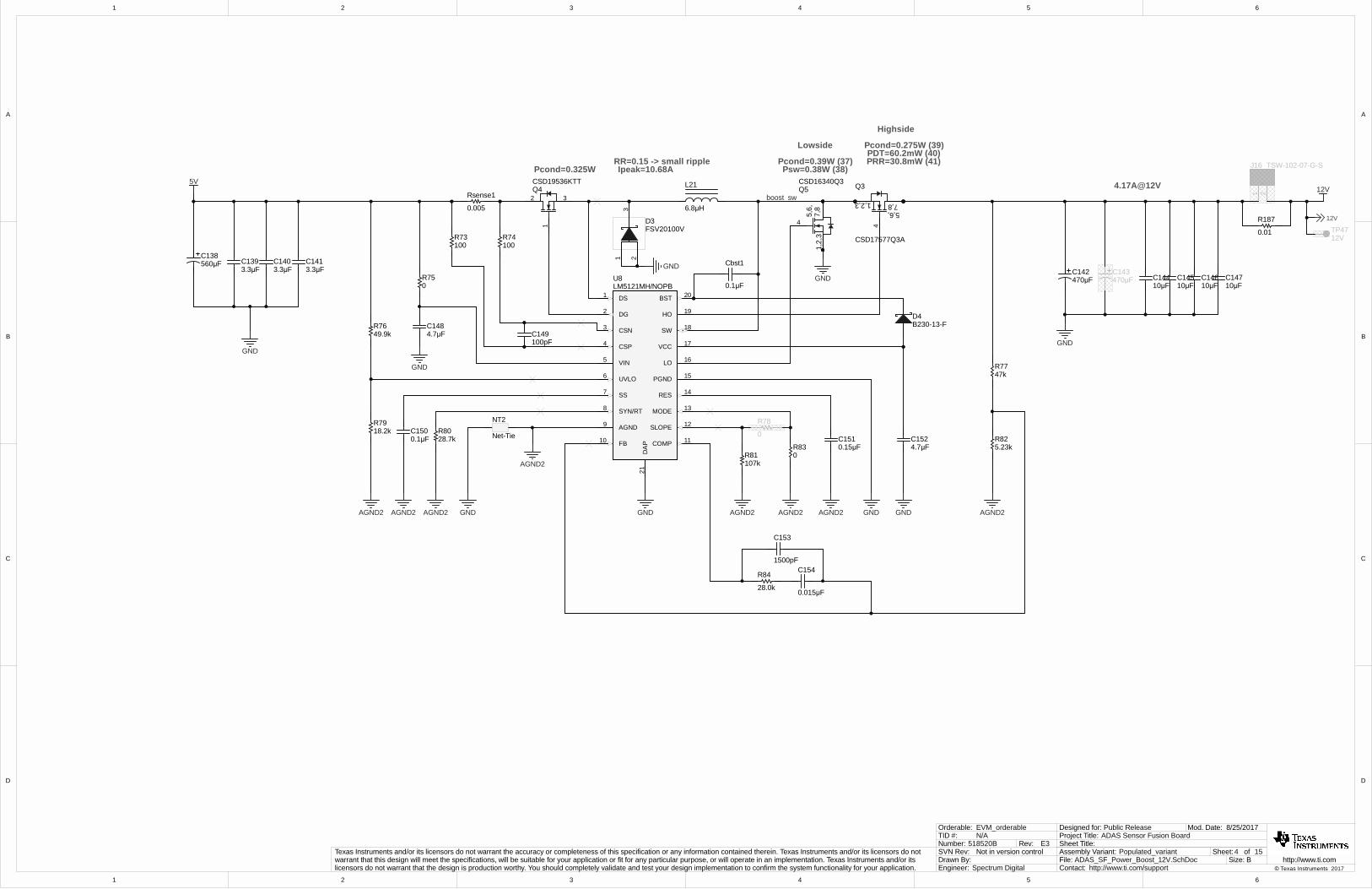
ADAS_SF_Power_Boost_12V.SchDoc
Sheet Title:
Size:
Mod. Date:
File:Sheet: of
B http://www.ti.comContact: http://www.ti.com/support
ADAS Sensor Fusion BoardProject Title:Designed for: Public Release
Assembly Variant: Populated_variant
© Texas Instruments 2017Drawn By:Engineer: Spectrum Digital
Texas Instruments and/or its licensors do not warrant the accuracy or completeness of this specification or any information contained therein. Texas Instruments and/or its licensors do not warrant that this design will meet the specifications, will be suitable for your application or fit for any particular purpose, or will operate in an implementation. Texas Instruments and/or its licensors do not warrant that the design is production worthy. You should completely validate and test your design implementation to confirm the system functionality for your application.
Not in version controlSVN Rev:518520BNumber: Rev: E3
TID #: N/AOrderable: EVM_orderable
CSN3
CSP4
VIN5
UVLO6
SS7
SYN/RT8
AGND9
FB10 COMP 11
SLOPE 12
MODE 13
RES 14
PGND 15
LO 16
VCC 17
SW 18
HO 19
BST 20DS1
DG2
DA
P21
U8LM5121MH/NOPB
5V
49.9kR76
0.1µFC150
28.7kR80
GND
0.005
Rsense1
6.8µH
L21
0.1µF
Cbst1GND
4
7,8
1,2,
35,
6,
Q5CSD16340Q3
GND
12V
4.7µFC152
5.23kR82
28.0k
R84
470µFC142
1 2
J16 TSW-102-07-G-S
18.2kR79
0R83
100pFC149
100R74
100R73
3.3µFC141
3.3µFC140
3.3µFC139560µF
C138
470µFC143
10µFC144
10µFC145
10µFC146
10µFC147
Pcond=0.39W (37)Psw=0.38W (38)
Pcond=0.275W (39)PDT=60.2mW (40)PRR=30.8mW (41)
Highside
Lowside
RR=0.15 -> small rippleIpeak=10.68A
4.17A@12V
0
R78
4
7,81,2,35,6,
Q3
CSD17577Q3A
4.7µFC148
0R75
D4B230-13-F
1
32Q4CSD19536KTTPcond=0.325W
12V
107kR81
GND
1500pF
C153
0.015µF
C154
47kR77
NT2
Net-Tie
AGND2
AGND2 AGND2 AGND2 AGND2AGND2 AGND2 AGND2 GND GNDGNDGND
GND
0.15µFC151
boost_sw
TP4712V
13
2
D3FSV20100V 0.01
R187
1
1
2
2
3
3
4
4
5
5
6
6
D D
C C
B B
A A
5 15
9/25/2017
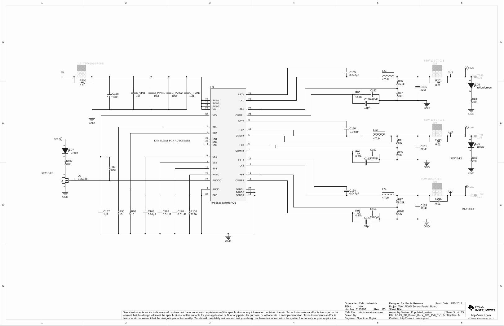
ADAS_SF_Power_Buck_3V3_1V8_1V1.SchDoc
Sheet Title:
Size:
Mod. Date:
File:Sheet: of
B http://www.ti.comContact: http://www.ti.com/support
ADAS Sensor Fusion BoardProject Title:Designed for: Public Release
Assembly Variant: Populated_variant
© Texas Instruments 2017Drawn By:Engineer: Spectrum Digital
Texas Instruments and/or its licensors do not warrant the accuracy or completeness of this specification or any information contained therein. Texas Instruments and/or its licensors do not warrant that this design will meet the specifications, will be suitable for your application or fit for any particular purpose, or will operate in an implementation. Texas Instruments and/or its licensors do not warrant that the design is production worthy. You should completely validate and test your design implementation to confirm the system functionality for your application.
Not in version controlSVN Rev:518520BNumber: Rev: E3
TID #: N/AOrderable: EVM_orderable
GND
0.01µFC170
0.01µFC169
0.01µFC168
21.5kR100
10R99
5V
1µFC167
100kR89
10R90
10µFC_PVIN3
10µFC_PVIN2
10µFC_PVIN1
GND
1µFC_VIN1
47µFC158
0.047µFC164
4.7µH
L24
GND
22µFC165
8.25kR97
4.87k
R98
91pF
C1712700pF
C166
0.047µFC155
4.7µH
L22
GND
10kR87
45.3kR85
22µFC156
14.0k
R86
1500pF
C157
18pF
C159
0.047µFC160
4.7µH
L23
GND
10kR95
22µFC161
20kR91
6.98k
R94
2200pF
C162
C163
10kR101
1 2
J17 TSW-102-07-G-S
1 2
J18TSW-102-07-G-S
1 2
J19TSW-102-07-G-S
1 2
J20TSW-102-07-G-S
220R96
GND
Yellow
12
D6
1V8
360R102
Green
21
D7
1V1
GND
Yellow/green
12
D5
360R88
3V33V3
1V8
1V1
TP493V3
TP481V8
TP501V1
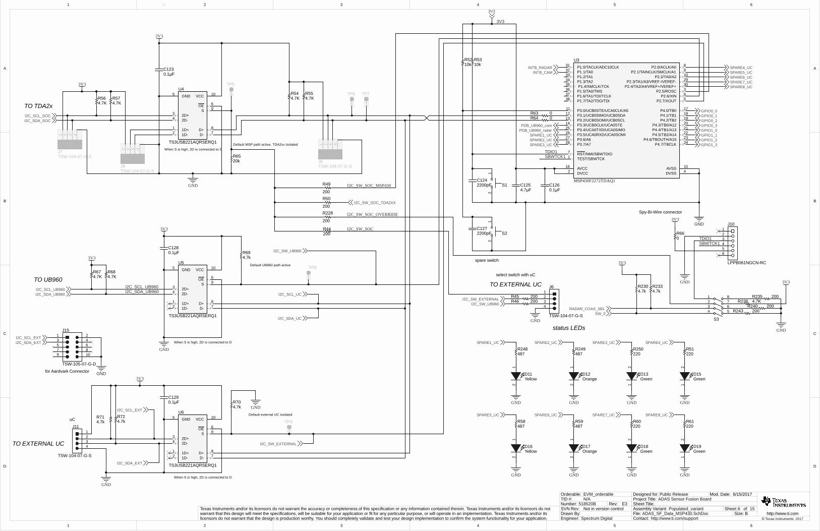
ENx FLOAT FOR AUTOSTART
SDA2
AGND4
FB2 6EN232
BST2 9
LX2 10
PGND2 11
PVIN212
PVIN313
PGND3 14
LX3 15
BST3 16
FB3 19ROSC21
VOUT2 5
COMP1 23
SS124
FB1 22
EN131
BST1 25
LX1 26
PGND1 27
PVIN128
V7V30
PAD33
SCL3
COMP2 7
COMP3 18
SS28
SS317
PGOOD20
VIN29
EN31
U9
TPS65263QRHBRQ1
0.01
R200
0.01
R201
0.01
R214
0.01
R215
REV B/E3
1
23 Q2
BSS138
3V3
GND
REV B/E3
REV B/E3
1
1
2
2
3
3
4
4
5
5
6
6
D D
C C
B B
A A
6 15
6/15/2017
ADAS_SF_Data_MSP430.SchDoc
Sheet Title:
Size:
Mod. Date:
File:Sheet: of
B http://www.ti.comContact: http://www.ti.com/support
ADAS Sensor Fusion BoardProject Title:Designed for: Public Release
Assembly Variant: Populated_variant
© Texas Instruments 2017Drawn By:Engineer: Spectrum Digital
Texas Instruments and/or its licensors do not warrant the accuracy or completeness of this specification or any information contained therein. Texas Instruments and/or its licensors do not warrant that this design will meet the specifications, will be suitable for your application or fit for any particular purpose, or will operate in an implementation. Texas Instruments and/or its licensors do not warrant that the design is production worthy. You should completely validate and test your design implementation to confirm the system functionality for your application.
Not in version controlSVN Rev:518520BNumber: Rev: E3
TID #: N/AOrderable: EVM_orderable
TO EXTERNAL UC1D+1
1D-2
2D+3
2D-4
GND5
OE 6
D- 7D+ 8
S 9
VCC 10U6
TS3USB221AQRSERQ1
GND
4.7kR71
4.7kR72
0.1µFC129
3V3
4
123
J11
TSW-104-07-G-S
When S is high, 2D is connected to D
4.7kR70
I2C_SW_EXTERNAL
TP9
I2C_SCL_EXT
I2C_SDA_EXT
TO UB960I2C_SCL_UB960I2C_SDA_UB960
1D+1
1D-2
2D+3
2D-4
GND5
OE 6
D- 7D+ 8
S 9
VCC 10U5
TS3USB221AQRSERQ1
GND
0.1µFC128
I2C_SCL_UB960I2C_SDA_UB960
3V3
When S is high, 2D is connected to D
4.7kR69
I2C_SCL_UC
I2C_SDA_UC
I2C_SW_UB960
TP8
3V3
I2C_SDA_SOCI2C_SCL_SOC
1D+1
1D-2
2D+3
2D-4
GND5
OE 6
D- 7D+ 8
S 9
VCC 10U4
TS3USB221AQRSERQ1
4.7KR54
4.7KR55
4.7KR56
4.7KR57
GND
41 2 3
J8TSW-104-07-G-S
41 2 3
J9TSW-104-07-G-S
41 2 3
J7TSW-104-07-G-S
TO TDA2x
When S is high, 2D is connected to D
TP5
TP6 TP7
0.1µFC123
3V3
TEST/SBWTCK1
DVCC2
P2.5/ROSC 3
DVSS 4
P2.7/XOUT 5P2.6/XIN 6
RST/NMI/SBWTDIO7
P2.0/ACLK/A0 8
P2.1/TAINCLK/SMCLK/A1 9
P2.2/TA0/A2 10
P3.0/UCB0STE/UCA0CLK/A511
P3.1/UCB0SIMO/UCB0SDA12
P3.2/UCB0SOMI/UCB0SCL13
P3.3/UCB0CLK/UCA0STE14
AVSS 15AVCC16
P4.0/TB0 17
P4.1/TB1 18
P4.2/TB2 19
P4.3/TB0/A12 20
P4.4/TB1/A13 21
P4.5/TB2/A14 22
P4.6/TBOUTH/A15 23
P4.7/TBCLK 24
P3.4/UCA0TXD/UCA0SIMO25
P3.5/UCA0RXD/UCA0SOMI26
P3.6/A627
P3.7/A728
P2.3/TA1/A3/VREF-/VEREF- 29
P2.4/TA2/A4/VREF+/VEREF+ 30
P1.0/TACLK/ADC10CLK31
P1.1/TA032
P1.2/TA133
P1.3/TA234
P1.4/SMCLK/TCK35
P1.5/TA0/TMS36
P1.6/TA1/TDI/TCLK37
P1.7/TA2/TDO/TDI38
U3
MSP430F2272TDAQ1
GND
4.7µFC125
0.1µFC126
21
S12200pFC124
SBWTCK1TDIO1
0R630R64
3V3
4.7KR67
4.7KR68
200R44
200R45200R46
4
123
J6
TSW-104-07-G-SGND
TO EXTERNAL UC
PDB_UB960_radarPDB_UB960_cam
10kR53
21
S22200pFC127
10kR52
GND
3V3
TDIO1SBWTCK1
0R66
INTB_RADARINTB_CAM
GPIO0_0GPIO0_1GPIO0_2GPIO0_3GPIO1_0GPIO1_1GPIO1_2GPIO1_3
3V3
3V3
123456
J10
LPPB061NGCN-RC
GND GND
487R248
Yellow
12
D11
487R249
Orange
12
D12
SPARE1_UC SPARE2_UC
GND
SPARE3_UC
220R250
Green
21
D13
SPARE1_UCSPARE2_UCSPARE3_UC
1 23 45 67 89 10
J15
TSW-105-07-G-D
I2C_SDA_EXTI2C_SCL_EXT
GNDfor Aardvark Connector
uC
select switch with uC
spare switch
Spy-Bi-Wire connector
status LEDs
I2C_SW_EXTERNALI2C_SW_UB960
GND
220R51
Green
21
D15
SPARE4_UC
GND GND
487R58
Yellow
12
D16
487R59
Orange
12
D17
SPARE5_UC SPARE6_UC
GND
SPARE7_UC
220R60
Green
21
D18
GND
220R61
Green
21
D19
SPARE8_UC
SPARE4_UCSPARE5_UCSPARE6_UCSPARE7_UCSPARE8_UC
200
R50I2C_SW_SOC_TDA2XX
200
R49
I2C_SW_SOC
I2C_SW_SOC_MSP430
GNDDefault external UC isolated
Default UB960 path active
Default MSP path active, TDA2xx isolated
63
1 82 7
54
S3SW_0
RADAR_COAX_SEL
4.7kR230
4.7kR233
3V3
200R243200R240
GND
200
R228
3V3
I2C_SW_SOC_OVERRIDE
20kR65
4.7KR238200R235
1
1
2
2
3
3
4
4
5
5
6
6
D D
C C
B B
A A
7 15
10/18/2017
ADAS_SF_Data_Deserializer_Camera.SchDoc
Sheet Title:
Size:
Mod. Date:
File:Sheet: of
B http://www.ti.comContact: http://www.ti.com/support
ADAS Sensor Fusion BoardProject Title:Designed for: Public Release
Assembly Variant: Populated_variant
© Texas Instruments 2017Drawn By:Engineer: Spectrum Digital
Texas Instruments and/or its licensors do not warrant the accuracy or completeness of this specification or any information contained therein. Texas Instruments and/or its licensors do not warrant that this design will meet the specifications, will be suitable for your application or fit for any particular purpose, or will operate in an implementation. Texas Instruments and/or its licensors do not warrant that the design is production worthy. You should completely validate and test your design implementation to confirm the system functionality for your application.
Not in version controlSVN Rev:518520BNumber: Rev: E3
TID #: N/AOrderable: EVM_orderable
VDD18_P31
VDD18_P22
PDB 3
TESTEN 4
REFCLOCK 5
INTB 6
I2C_SDA2 7I2C_SCL2 8
GPIO[0]9
GPIO[1]10
I2C_SDA 11I2C_SCL 12
VDDL113
GPIO[2]14
GPIO[3]15
VDDIO16
GPIO[4]17
GPIO[5]18
GPIO[6]19
GPIO[7]20
VDD_CSI021
CSI0_CLK- 22CSI0_CLK+ 23
CSI0_D0- 24CSI0_D0+ 25
CSI0_D1- 26CSI0_D1+ 27
CSI0_D2- 28CSI0_D2+ 29
CSI0_D3- 30CSI0_D3+ 31
VDD18A32
VDD_CSI133
CSI1_CLK- 34CSI1_CLK+ 35
CSI1_D0- 36CSI1_D0+ 37
CSI1_D1- 38CSI1_D1+ 39
CSI1_D2- 40CSI1_D2+ 41
CSI1_D3- 42CSI1_D3+ 43
VDDL244
MODE 45
IDX 46
VDD18_P147VDD18_P048
VDD18_FPD049
RIN0+50
RIN0-51
VDD_FPD152
RIN1+53
RIN1-54
VDD18_FPD155
LPTXP56
LPTXN57
VDD18_FPD258
RIN2+59
RIN2-60
VDD_FPD261
RIN3+62
RIN3-63
VDD18_FPD364
DAP 65
U1
DS90UB960TRGCRQ1
cam_0_pcam_0_ncam_1_pcam_1_ncam_2_pcam_2_ncam_3_pcam_3_n
cam_CSI0_D0_Pcam_CSI0_D0_N
cam_CSI0_D1_Ncam_CSI0_D1_P
cam_CSI0_CLK_Pcam_CSI0_CLK_N
VDD18_P0_CAMVDD18_P1_CAMVDD18_P2_CAMVDD18_P3_CAM
VDD18A_CAM
VDDFPD18_CAM
VDDL_1V1_CAM
VDDCSI_1V1_CAM
VDDFPD_1V1_CAM
VDDIO_CAM
I2C_SCL_UB960I2C_SDA_UB960
0.033µFC35
0.033µFC41
100R29
10µFC21
120 ohm
L4
10µFC22
1µFC23
0.1µFC24
0.01µFC25
10µFC27
120 ohm
L5
0.01µFC31
0.01µFC32
0.01µFC33
0.01µFC34
10µFC28
1µFC29
0.1µFC30
120 ohm
L6
10µFC37
1µFC38
0.1µFC39
0.01µFC40
120 ohm
L7
10µFC43
1µFC44
0.1µFC45
0.01µFC46
120 ohm
L8
10µFC48
1µFC49
0.1µFC50
0.01µFC51
120 ohm
L9
10µFC53
1µFC54
0.1µFC55
0.01µFC56
10µFC36
10µFC42
10µFC47
10µFC52
GND
120 ohm
L3
10µFC13
120 ohm
L2
10µFC7
120 ohm
L1
10µFC1
0.01µFC5
0.01µFC6
10µFC2
1µFC3
0.1µFC4
0.01µFC11
0.01µFC12
10µFC8
1µFC9
0.1µFC10
0.01µFC17
0.01µFC18
10µFC14
1µFC15
0.1µFC16
GND
10µFC57
120 ohm
L10
10µFC58
1µFC59
0.1µFC60
0.01µFC61
GND
VDD18_P0_CAM
VDD18_P1_CAM
VDD18_P2_CAM
VDD18_P3_CAM
VDD18A_CAM
VDDL_1V1_CAM
VDDCSI_1V1_CAM
VDDFPD_1V1_CAM
VDDFPD18_CAM
VDDIO_CAM
cam_CSI0_D2_Pcam_CSI0_D2_N
cam_CSI0_D3_Ncam_CSI0_D3_P
UB960_CLK_CAM
GND
10kR30
Coax / Twisted Pair
487R22
PDB_UB960_cam
13.3kR21
40.2kR25
40.2kR27
13.3kR23
82.5kR24
102kR28
I2C ID: 0x3D
GND
GND
GND
Mode selection
LPTX1_PLPTX1_N
GPIO1_0GPIO1_1GPIO1_2GPIO1_3
INTB_CAM
1V1
1V8
3V3
1V81V8
0.1µFC19
10µFC20
0.1µFC26
11
TP1
TP-025-SMT
11
TP2
TP-025-SMT
SYNC_CAMERA
631
82
7 54
S4
GND
3V3
10kR26
REV B/E3
10kR186
3V3
REV B/E3
REV B/E3
1
1
2
2
3
3
4
4
5
5
6
6
D D
C C
B B
A A
8 15
9/26/2017
ADAS_SF_Data_Deserializer_Radar.SchDoc
Sheet Title:
Size:
Mod. Date:
File:Sheet: of
B http://www.ti.comContact: http://www.ti.com/support
ADAS Sensor Fusion BoardProject Title:Designed for: Public Release
Assembly Variant: Populated_variant
© Texas Instruments 2017Drawn By:Engineer: Spectrum Digital
Texas Instruments and/or its licensors do not warrant the accuracy or completeness of this specification or any information contained therein. Texas Instruments and/or its licensors do not warrant that this design will meet the specifications, will be suitable for your application or fit for any particular purpose, or will operate in an implementation. Texas Instruments and/or its licensors do not warrant that the design is production worthy. You should completely validate and test your design implementation to confirm the system functionality for your application.
Not in version controlSVN Rev:518520BNumber: Rev: E3
TID #: N/AOrderable: EVM_orderable
VDD18_P31
VDD18_P22
PDB 3
TESTEN 4
REFCLOCK 5
INTB 6
I2C_SDA2 7I2C_SCL2 8
GPIO[0]9
GPIO[1]10
I2C_SDA 11I2C_SCL 12
VDDL113
GPIO[2]14
GPIO[3]15
VDDIO16
GPIO[4]17
GPIO[5]18
GPIO[6]19
GPIO[7]20
VDD_CSI021
CSI0_CLK- 22CSI0_CLK+ 23
CSI0_D0- 24CSI0_D0+ 25
CSI0_D1- 26CSI0_D1+ 27
CSI0_D2- 28CSI0_D2+ 29
CSI0_D3- 30CSI0_D3+ 31
VDD18A32
VDD_CSI133
CSI1_CLK- 34CSI1_CLK+ 35
CSI1_D0- 36CSI1_D0+ 37
CSI1_D1- 38CSI1_D1+ 39
CSI1_D2- 40CSI1_D2+ 41
CSI1_D3- 42CSI1_D3+ 43
VDDL244
MODE 45
IDX 46
VDD18_P147VDD18_P048
VDD18_FPD049
RIN0+50
RIN0-51
VDD_FPD152
RIN1+53
RIN1-54
VDD18_FPD155
LPTXP56
LPTXN57
VDD18_FPD258
RIN2+59
RIN2-60
VDD_FPD261
RIN3+62
RIN3-63
VDD18_FPD364
DAP 65
U2
DS90UB960TRGCRQ1
radar_0_pradar_0_nradar_1_pradar_1_nradar_2_pradar_2_nradar_3_pradar_3_n
radar_CSI0_D0_Pradar_CSI0_D0_N
radar_CSI0_D1_Nradar_CSI0_D1_P
radar_CSI0_D2_Pradar_CSI0_D2_Nradar_CSI0_D3_Pradar_CSI0_D3_N
radar_CSI0_CLK_Pradar_CSI0_CLK_N
GND
10kR43
VDD18_P0_RADARVDD18_P1_RADARVDD18_P2_RADARVDD18_P3_RADAR
VDD18A_RADAR
VDDFPD18_RADAR
VDDL_1V1_RADAR
VDDCSI_1V1_RADAR
VDDFPD_1V1_RADAR
VDDIO_RADAR
I2C_SCL_UB960I2C_SDA_UB960
Coax / Twisted Pair
487R35
PDB_UB960_radar
113kR34
88.7kR38
40.2kR40
13.3kR36
82.5kR37
102kR41
I2C ID: 0x36
UB960_CLK_RADAR
VCC 4E/D1
GND2 OUT 3
25MHz
Y110k
R31
GND
UB960_CLK_RADAR
UB960_CLK_CAM
10µFC80
120 ohm
L14
10µFC81
1µFC82
0.1µFC83
0.01µFC84
10µFC87
120 ohm
L15
0.01µFC91
0.01µFC92
0.01µFC93
0.01µFC94
10µFC88
1µFC89
0.1µFC90
120 ohm
L16
10µFC97
1µFC98
0.1µFC99
0.01µFC100
120 ohm
L17
10µFC104
1µFC105
0.1µFC106
0.01µFC107
120 ohm
L18
10µFC109
1µFC110
0.1µFC111
0.01µFC112
120 ohm
L19
10µFC114
1µFC115
0.1µFC116
0.01µFC117
10µFC96
10µFC103
10µFC108
10µFC113
GND
120 ohm
L13
10µFC74
120 ohm
L12
10µFC68
120 ohm
L11
10µFC62
0.01µFC66
0.01µFC67
10µFC63
1µFC64
0.1µFC65
0.01µFC72
0.01µFC73
10µFC69
1µFC70
0.1µFC71
0.01µFC78
0.01µFC79
10µFC75
1µFC76
0.1µFC77
GND
10µFC118
120 ohm
L20
10µFC119
1µFC120
0.1µFC121
0.01µFC122
GND
VDD18_P0_RADAR
VDD18_P1_RADAR
VDD18_P2_RADAR
VDD18_P3_RADAR
VDD18A_RADAR
VDDL_1V1_RADAR
VDDCSI_1V1_RADAR
VDDFPD_1V1_RADAR
VDDFPD18_RADAR
GND
10kR39
GND
GND
Mode selection
0.033µFC101
0.033µFC102
100R42
VDDIO_RADAR
LPTX0_PLPTX0_N
GPIO0_0GPIO0_1GPIO0_2GPIO0_3
INTB_RADAR
1V8
1V1
3V3
1V8
1V8
0.1µFC85
10µFC86
0.1µFC95
11
TP3
TP-025-SMT
11
TP4
TP-025-SMT
TP55CLK
0
R32
0
R33
0
R251
0
R252
SYNC_RADAR
631
82
7 54
S5
GND
REV B/E3
3V3
10kR245
3V3
REV B/E3
0.1µFC313
GND
3V3
REV B/E3
120 ohm
L78
REV B/E3
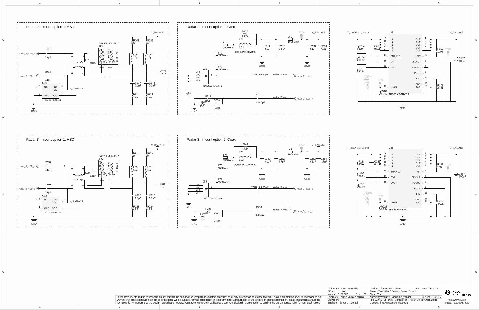
Place 10uF, 1uF, 0.1uF and 0.01uF bypass caps on bottom of board, close to U1 VDD pins
1
1
2
2
3
3
4
4
5
5
6
6
D D
C C
B B
A A
9 15
6/15/2017
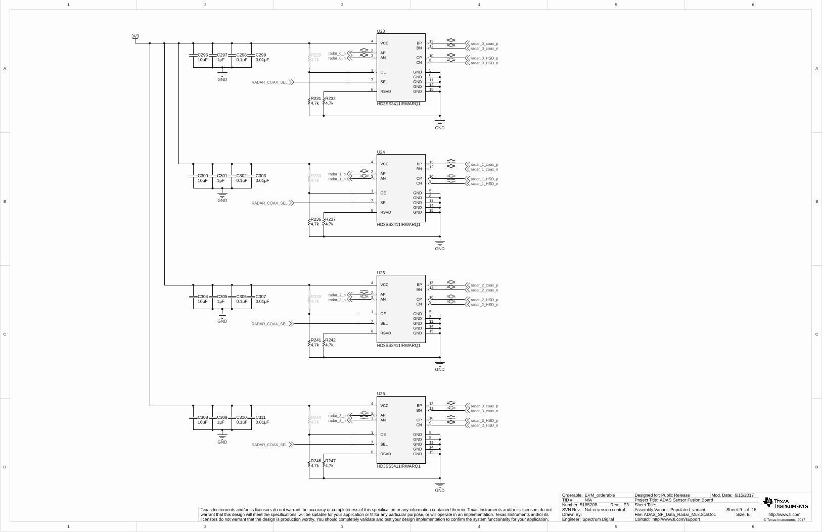
ADAS_SF_Data_Radar_Mux.SchDoc
Sheet Title:
Size:
Mod. Date:
File:Sheet: of
B http://www.ti.comContact: http://www.ti.com/support
ADAS Sensor Fusion BoardProject Title:Designed for: Public Release
Assembly Variant: Populated_variant
© Texas Instruments 2017Drawn By:Engineer: Spectrum Digital
Texas Instruments and/or its licensors do not warrant the accuracy or completeness of this specification or any information contained therein. Texas Instruments and/or its licensors do not warrant that this design will meet the specifications, will be suitable for your application or fit for any particular purpose, or will operate in an implementation. Texas Instruments and/or its licensors do not warrant that the design is production worthy. You should completely validate and test your design implementation to confirm the system functionality for your application.
Not in version controlSVN Rev:518520BNumber: Rev: E3
TID #: N/AOrderable: EVM_orderable
OE1
AP2
AN3
VCC4
GND 5
RSVD6
SEL7GND 8
CN 9CP 10
GND 11
BN 12BP 13
GND 14
GND 15
U23
HD3SS3411IRWARQ1
radar_0_pradar_0_n
4.7kR232
4.7kR231
4.7kR229
10µFC296
1µFC297
0.01µFC299
3V3
GND
OE1
AP2
AN3
VCC4
GND 5
RSVD6
SEL7GND 8
CN 9CP 10
GND 11
BN 12BP 13
GND 14
GND 15
U24
HD3SS3411IRWARQ1
radar_1_pradar_1_n
4.7kR237
4.7kR236
4.7kR234
10µFC300
1µFC301
0.01µFC303
GND
OE1
AP2
AN3
VCC4
GND 5
RSVD6
SEL7GND 8
CN 9CP 10
GND 11
BN 12BP 13
GND 14
GND 15
U25
HD3SS3411IRWARQ1
radar_2_pradar_2_n
4.7kR242
4.7kR241
4.7kR239
10µFC304
1µFC305
0.01µFC307
GND
OE1
AP2
AN3
VCC4
GND 5
RSVD6
SEL7GND 8
CN 9CP 10
GND 11
BN 12BP 13
GND 14
GND 15
U26
HD3SS3411IRWARQ1
radar_3_pradar_3_n
4.7kR247
4.7kR246
4.7kR244
10µFC308
1µFC309
0.01µFC311
GND
radar_0_HSD_nradar_0_HSD_p
radar_0_coax_nradar_0_coax_p
GND
GND
GND
GND
0.1µFC298
0.1µFC302
0.1µFC306
0.1µFC310
radar_1_coax_nradar_1_coax_p
radar_1_HSD_nradar_1_HSD_p
radar_2_coax_nradar_2_coax_p
radar_2_HSD_nradar_2_HSD_p
radar_3_coax_nradar_3_coax_p
radar_3_HSD_nradar_3_HSD_p
RADAR_COAX_SEL
RADAR_COAX_SEL
RADAR_COAX_SEL
RADAR_COAX_SEL
1
1
2
2
3
3
4
4
5
5
6
6
D D
C C
B B
A A
10 15
1/5/2018
ADAS_SF_Data_Connection_Radar_01.SchDoc
Sheet Title:
Size:
Mod. Date:
File:Sheet: of
B http://www.ti.comContact: http://www.ti.com/support
ADAS Sensor Fusion BoardProject Title:Designed for: Public Release
Assembly Variant: Populated_variant
© Texas Instruments 2017Drawn By:Engineer: Spectrum Digital
Texas Instruments and/or its licensors do not warrant the accuracy or completeness of this specification or any information contained therein. Texas Instruments and/or its licensors do not warrant that this design will meet the specifications, will be suitable for your application or fit for any particular purpose, or will operate in an implementation. Texas Instruments and/or its licensors do not warrant that the design is production worthy. You should completely validate and test your design implementation to confirm the system functionality for your application.
Not in version controlSVN Rev:518520BNumber: Rev: E3
TID #: N/AOrderable: EVM_orderable
0.1µFC247
0.1µFC248
49.9R182
49.9R183
VCC 1
NC2 IO1 3
GND4
IO2 5
U16
TPD2E001DRLR
10µFC243
2 14 3
PAIR
A1
PAIR
A2
EM
ITTER
J29D4S20L-40MA5-Z
GND
GND
0.1µF
C241
0.1µF
C244
V_RADAR0
V_RADAR0
Radar 0 - mount option 2: Coax
GND
57.6
R184
200
R185
240pF
C250
GND
GND
0.1µFC238
0.1µFC236
GND
radar_0_coax_p0.033µFC245
radar_0_coax_n
0.015µF
C249
1MH1MH2MH3MH4
J28
59S20X-400L5-Y
TP28 V_RADAR0
Radar 0 - mount option 1: HSD
0R1680R1690R1700R171
V_RADAR1_unprotV_RADAR2_unprot
V_RADAR3_unprot
V_RADAR0_unprot
1 2 3
J27TSW-103-07-G-S
5V 12V
Power Selection
DEVSLP 1
PGOOD 2
PGTH 3
OUT 4
OUT 5
OUT 6
OUT 7
OUT 8
IN9
IN10
IN11
IN12
IN13
EN/UVLO14
OVP15
GND 16
ILIM 17
DVDT18
IMON19
FLT 20
PAD 21
U15
TPS25940ARVCR
V_RADAR0V_RADAR0_unprot
309kR176
69.8kR178
GND
16.9kR181
1000
pF
C246TP30
44.2kR180
100kR177 TP290.1µF
C240
30.9kR179
100µFC242
10µHL52
10µHL53
0.1µFC262
0.1µFC263
49.9R195
49.9R196
VCC 1
NC2 IO1 3
GND4
IO2 5
U18
TPD2E001DRLR
10µFC258
2 14 3
PAIR
A1
PAIR
A2
EM
ITTER
J31D4S20L-40MA5-Z
GND
GND
0.1µF
C256
0.1µF
C259
radar_1_HSD_n
radar_1_HSD_p
V_RADAR1
V_RADAR1
Radar 1 - mount option 2: Coax
GND
57.6
R198
200
R199
240pF
C265
GND
GND
4.7µFC254
4.7µFC252
0.1µFC253
0.1µFC251
GND
radar_1_coax_p0.033µFC260
radar_1_coax_n
0.015µF
C264
1MH1MH2MH3MH4
J30
59S20X-400L5-Y
TP31 V_RADAR1
Radar 1 - mount option 1: HSD
DEVSLP 1
PGOOD 2
PGTH 3
OUT 4
OUT 5
OUT 6
OUT 7
OUT 8
IN9
IN10
IN11
IN12
IN13
EN/UVLO14
OVP15
GND 16
ILIM 17
DVDT18
IMON19
FLT 20
PAD 21
U17
TPS25940ARVCR
V_RADAR1V_RADAR1_unprot
309kR190
69.8kR192
GND
16.9kR197
1000
pF
C261TP33
44.2kR194
100kR191 TP320.1µF
C255
30.9kR193
100µFC257
radar_0_HSD_n
radar_0_HSD_p
radar_0_coax_n
radar_0_coax_p
radar_1_coax_n
radar_1_coax_p
1000 ohm
L49
0R174
0R175
0R188
0R189
123 4
L47
123 4
L54
4.7µFC239
4.7µFC237
10µHL45
10µHL46
1000 ohm
L42
1500 ohmL58
1500 ohmL57
1500 ohm
L55
4.02k
R125
1500 ohmL69
1500 ohmL65
1500 ohm
L64
4.02k
R126
Ilim = 89/Rlim(kohm)
88.7k for ~1Amp
139k for .64Amp
1500pf for inrush
10µH
L62
LQH3NPZ100MJRL
10µH
L51
LQH3NPZ100MJRL
1
1
2
2
3
3
4
4
5
5
6
6
D D
C C
B B
A A
11 15
1/5/2018
ADAS_SF_Data_Connection_Radar_02.SchDoc
Sheet Title:
Size:
Mod. Date:
File:Sheet: of
B http://www.ti.comContact: http://www.ti.com/support
ADAS Sensor Fusion BoardProject Title:Designed for: Public Release
Assembly Variant: Populated_variant
© Texas Instruments 2017Drawn By:Engineer: Spectrum Digital
Texas Instruments and/or its licensors do not warrant the accuracy or completeness of this specification or any information contained therein. Texas Instruments and/or its licensors do not warrant that this design will meet the specifications, will be suitable for your application or fit for any particular purpose, or will operate in an implementation. Texas Instruments and/or its licensors do not warrant that the design is production worthy. You should completely validate and test your design implementation to confirm the system functionality for your application.
Not in version controlSVN Rev:518520BNumber: Rev: E3
TID #: N/AOrderable: EVM_orderable
10µHL59
10µHL60
0.1µFC277
0.1µFC278
49.9R210
49.9R211
VCC 1
NC2 IO1 3
GND4
IO2 5
U20
TPD2E001DRLR
10µFC273
2 14 3
PAIR
A1
PAIR
A2
EM
ITTER
J33D4S20L-40MA5-Z
GND
GND
0.1µF
C271
0.1µF
C274
V_RADAR2
V_RADAR2
Radar 2 - mount option 2: Coax
GND
57.6
R212
200
R213
240pF
C280
GND
GND
0.1µFC268
0.1µFC266
GND
radar_2_coax_p0.033µFC275
radar_2_coax_n
0.015µF
C279
1MH1MH2MH3MH4
J32
59S20X-400L5-Y
TP34 V_RADAR2
Radar 2 - mount option 1: HSD
DEVSLP 1
PGOOD 2
PGTH 3
OUT 4
OUT 5
OUT 6
OUT 7
OUT 8
IN9
IN10
IN11
IN12
IN13
EN/UVLO14
OVP15
GND 16
ILIM 17
DVDT18
IMON19
FLT 20
PAD 21
U19
TPS25940ARVCR
V_RADAR2V_RADAR2_unprot
309kR204
69.8kR206
GND
16.9kR209
1000
pF
C276TP36
44.2kR208
100kR205 TP350.1µF
C270
30.9kR207
100µFC272
10µHL66
10µHL67
0.1µFC292
0.1µFC293
49.9R223
49.9R224
VCC 1
NC2 IO1 3
GND4
IO2 5
U22
TPD2E001DRLR
10µFC288
2 14 3
PAIR
A1
PAIR
A2
EM
ITTER
J35D4S20L-40MA5-Z
GND
GND
0.1µF
C286
0.1µF
C289
V_RADAR3
V_RADAR3
Radar 3 - mount option 2: Coax
GND
57.6
R226
200
R227
240pF
C295
GND
GND
4.7µFC284
4.7µFC282
0.1µFC283
0.1µFC281
GND
radar_3_coax_p0.033µFC290
radar_3_coax_n
0.015µF
C294
1MH1MH2MH3MH4
J34
59S20X-400L5-Y
TP37 V_RADAR3
Radar 3 - mount option 1: HSD
DEVSLP 1
PGOOD 2
PGTH 3
OUT 4
OUT 5
OUT 6
OUT 7
OUT 8
IN9
IN10
IN11
IN12
IN13
EN/UVLO14
OVP15
GND 16
ILIM 17
DVDT18
IMON19
FLT 20
PAD 21
U21
TPS25940ARVCR
V_RADAR3V_RADAR3_unprot
309kR218
69.8kR220
GND
16.9kR225
1000
pF
C291TP39
44.2kR222
100kR219 TP380.1µF
C285
30.9kR221
100µFC287
radar_2_coax_n
radar_2_coax_p
radar_3_coax_n
radar_3_coax_p
radar_3_HSD_n
radar_3_HSD_p
radar_2_HSD_n
radar_2_HSD_p
1000 ohm
L56
1000 ohm
L63
0R202
0R203
0R216
0R217
123 4
L61
123 4
L68
4.7µFC269
4.7µFC267
1500 ohmL73
1500 ohmL72
1500 ohm
L71
4.02k
R127
1500 ohmL77
1500 ohmL76
1500 ohm
L75
4.02k
R148
10µH
L74
LQH3NPZ100MJRL
10µH
L70
LQH3NPZ100MJRL
1
1
2
2
3
3
4
4
5
5
6
6
D D
C C
B B
A A
12 15
1/5/2018
ADAS_SF_Data_Connection_Cam_01.SchDoc
Sheet Title:
Size:
Mod. Date:
File:Sheet: of
B http://www.ti.comContact: http://www.ti.com/support
ADAS Sensor Fusion BoardProject Title:Designed for: Public Release
Assembly Variant: Populated_variant
© Texas Instruments 2017Drawn By:Engineer: Spectrum Digital
Texas Instruments and/or its licensors do not warrant the accuracy or completeness of this specification or any information contained therein. Texas Instruments and/or its licensors do not warrant that this design will meet the specifications, will be suitable for your application or fit for any particular purpose, or will operate in an implementation. Texas Instruments and/or its licensors do not warrant that the design is production worthy. You should completely validate and test your design implementation to confirm the system functionality for your application.
Not in version controlSVN Rev:518520BNumber: Rev: E3
TID #: N/AOrderable: EVM_orderable
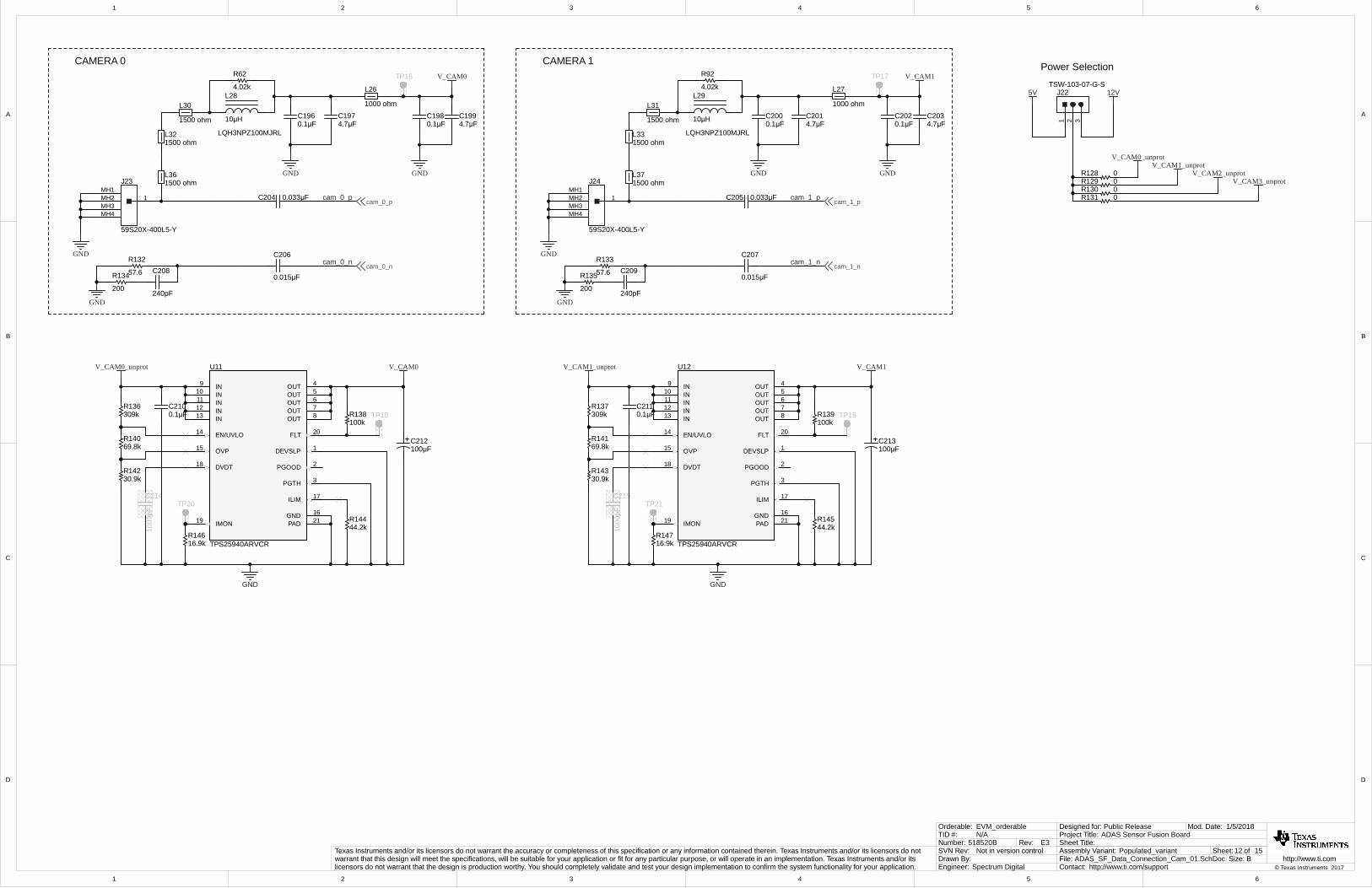
CAMERA 0
GND
CAMERA 1
57.6
R132
200
R134
240pF
C208
200
R135
240pF
C20957.6
R133
GNDGND
GND
0.1µFC198
0.1µFC196
GND
cam_0_p0.033µFC204
cam_0_n
0.015µF
C206
GND
0.1µFC202
0.1µFC200
GND
cam_1_p0.033µFC205
cam_1_n
0.015µF
C207GND
1MH1MH2MH3MH4
J23
59S20X-400L5-Y
1MH1MH2MH3MH4
J24
59S20X-400L5-Y
TP17TP16
cam_0_p
cam_0_n
cam_1_p
cam_1_n
V_CAM1V_CAM0
V_CAM1_unprotV_CAM2_unprot
V_CAM3_unprot
V_CAM0_unprot
1 2 3
J22TSW-103-07-G-S
5V 12V
Power Selection
0R1280R1290R1300R131
DEVSLP 1
PGOOD 2
PGTH 3
OUT 4
OUT 5
OUT 6
OUT 7
OUT 8
IN9
IN10
IN11
IN12
IN13
EN/UVLO14
OVP15
GND 16
ILIM 17
DVDT18
IMON19
FLT 20
PAD 21
U11
TPS25940ARVCR
309kR136
69.8kR140
GND
16.9kR146
1000
pF
C214TP20
44.2kR144
100kR138 TP180.1µF
C210
30.9kR142
100µFC212
DEVSLP 1
PGOOD 2
PGTH 3
OUT 4
OUT 5
OUT 6
OUT 7
OUT 8
IN9
IN10
IN11
IN12
IN13
EN/UVLO14
OVP15
GND 16
ILIM 17
DVDT18
IMON19
FLT 20
PAD 21
U12
TPS25940ARVCR
309kR137
69.8kR141
GND
16.9kR147
1000
pF
C215TP21
44.2kR145
100kR139 TP190.1µF
C211
30.9kR143
100µFC213
V_CAM0_unprot V_CAM1_unprot V_CAM1V_CAM0
1000 ohm
L27
1000 ohm
L26
4.7µFC197
4.7µFC199
4.7µFC203
4.7µFC201
1500 ohmL36
1500 ohmL32
1500 ohm
L30
4.02k
R62
1500 ohmL37
1500 ohmL33
1500 ohm
L31
4.02k
R92
10µH
L28
LQH3NPZ100MJRL
10µH
L29
LQH3NPZ100MJRL
1
1
2
2
3
3
4
4
5
5
6
6
D D
C C
B B
A A
13 15
1/5/2018
ADAS_SF_Data_Connection_Cam_02.SchDoc
Sheet Title:
Size:
Mod. Date:
File:Sheet: of
B http://www.ti.comContact: http://www.ti.com/support
ADAS Sensor Fusion BoardProject Title:Designed for: Public Release
Assembly Variant: Populated_variant
© Texas Instruments 2017Drawn By:Engineer: Spectrum Digital
Texas Instruments and/or its licensors do not warrant the accuracy or completeness of this specification or any information contained therein. Texas Instruments and/or its licensors do not warrant that this design will meet the specifications, will be suitable for your application or fit for any particular purpose, or will operate in an implementation. Texas Instruments and/or its licensors do not warrant that the design is production worthy. You should completely validate and test your design implementation to confirm the system functionality for your application.
Not in version controlSVN Rev:518520BNumber: Rev: E3
TID #: N/AOrderable: EVM_orderable
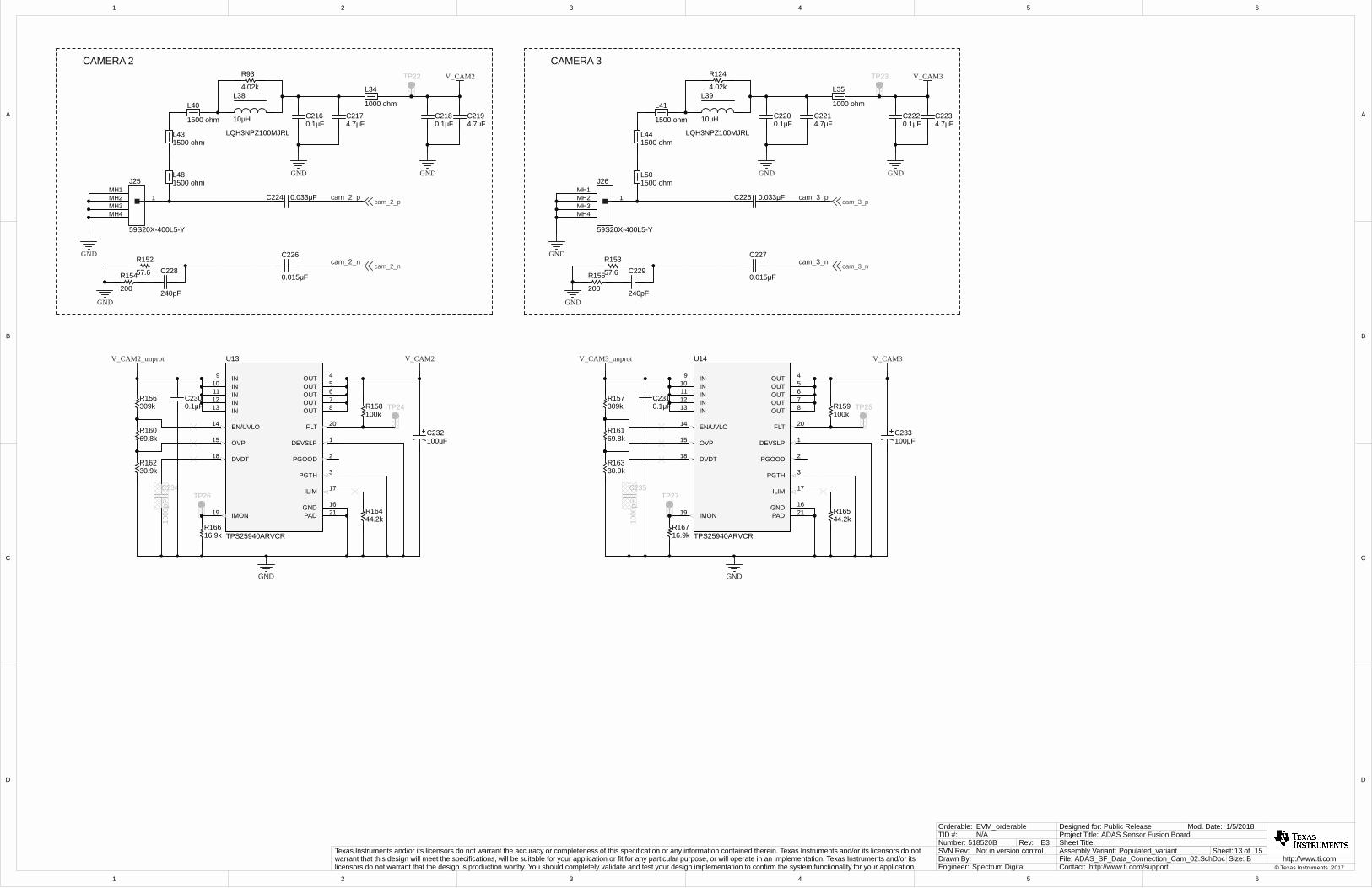
CAMERA 2
cam_2_p
CAMERA 3
200
R154
240pF
C22857.6
R152
200
R155
240pF
C22957.6
R153
GND GND
GND
0.1µFC218
0.1µFC216
GND
cam_2_n
0.015µF
C226
0.033µFC224
GND
0.1µFC222
0.1µFC220
GND
cam_3_p0.033µFC225
cam_3_n
0.015µF
C227GND GND
1MH1MH2MH3MH4
J25
59S20X-400L5-Y
1MH1MH2MH3MH4
J26
59S20X-400L5-Y
TP22 TP23
cam_2_p
cam_2_n
cam_3_p
cam_3_n
V_CAM3V_CAM2
DEVSLP 1
PGOOD 2
PGTH 3
OUT 4
OUT 5
OUT 6
OUT 7
OUT 8
IN9
IN10
IN11
IN12
IN13
EN/UVLO14
OVP15
GND 16
ILIM 17
DVDT18
IMON19
FLT 20
PAD 21
U13
TPS25940ARVCR
309kR156
69.8kR160
GND
16.9kR166
1000
pF
C234TP26
44.2kR164
100kR158 TP240.1µF
C230
30.9kR162
100µFC232
DEVSLP 1
PGOOD 2
PGTH 3
OUT 4
OUT 5
OUT 6
OUT 7
OUT 8
IN9
IN10
IN11
IN12
IN13
EN/UVLO14
OVP15
GND 16
ILIM 17
DVDT18
IMON19
FLT 20
PAD 21
U14
TPS25940ARVCR
309kR157
69.8kR161
GND
16.9kR167
1000
pF
C235TP27
44.2kR165
100kR159 TP250.1µF
C231
30.9kR163
100µFC233
V_CAM2_unprot V_CAM3_unprot V_CAM3V_CAM2
1000 ohm
L34
1000 ohm
L35
4.7µFC217
4.7µFC223
4.7µFC221
4.7µFC219
1500 ohmL50
1500 ohmL44
1500 ohm
L41
4.02k
R124
1500 ohmL48
1500 ohmL43
1500 ohm
L40
4.02k
R93
10µH
L38
LQH3NPZ100MJRL
10µH
L39
LQH3NPZ100MJRL
1
1
2
2
3
3
4
4
5
5
6
6
D D
C C
B B
A A
14 15
8/25/2017
ADAS_SF_Data_CSI2_Connector.SchDoc
Sheet Title:
Size:
Mod. Date:
File:Sheet: of
B http://www.ti.comContact: http://www.ti.com/support
ADAS Sensor Fusion BoardProject Title:Designed for: Public Release
Assembly Variant: Populated_variant
© Texas Instruments 2017Drawn By:Engineer: Spectrum Digital
Texas Instruments and/or its licensors do not warrant the accuracy or completeness of this specification or any information contained therein. Texas Instruments and/or its licensors do not warrant that this design will meet the specifications, will be suitable for your application or fit for any particular purpose, or will operate in an implementation. Texas Instruments and/or its licensors do not warrant that the design is production worthy. You should completely validate and test your design implementation to confirm the system functionality for your application.
Not in version controlSVN Rev:518520BNumber: Rev: E3
TID #: N/AOrderable: EVM_orderable
GND
I2C_SDA_SOCI2C_SCL_SOC
0R1
0R20R3
0R40R5
0R60R7
0R80R9
0R100R11
0R120R15
0R160R17
0R18
0R14 0
R13
0R19
0R20
GND
radar_CSI0_D0_Pradar_CSI0_D0_N
radar_CSI0_D1_Nradar_CSI0_D1_P
radar_CSI0_D2_Pradar_CSI0_D2_N
radar_CSI0_CLK_Pradar_CSI0_CLK_N
radar_CSI0_D3_Pradar_CSI0_D3_N
cam_CSI0_D3_Pcam_CSI0_D3_N
cam_CSI0_CLK_Pcam_CSI0_CLK_N
cam_CSI0_D1_Ncam_CSI0_D1_P
cam_CSI0_D0_Pcam_CSI0_D0_N
cam_CSI0_D2_Ncam_CSI0_D2_P
13
24
57
68
911
1012
1315
1416
1719
1820
2123
2224
2527
2628
2931
3032
3335
3436
3739
3840
MP1 MP2MP3 MP4
J1
QTH-020-01-L-D-DP-A
cam_clk_pcam_clk_n
cam_d0_pcam_d0_n
cam_d1_pcam_d1_n
cam_d2_pcam_d2_n
cam_d3_pcam_d3_n
rad_clk_prad_clk_n
rad_d0_prad_d0_n
rad_d1_prad_d1_n
rad_d2_prad_d2_n
rad_d3_prad_d3_n
V_bat
21D14
VS-30BQ100HM3/9AT
VEVM_12v0
VEVM_3v3
VEVM_1v8
12
J40
1757242
GND
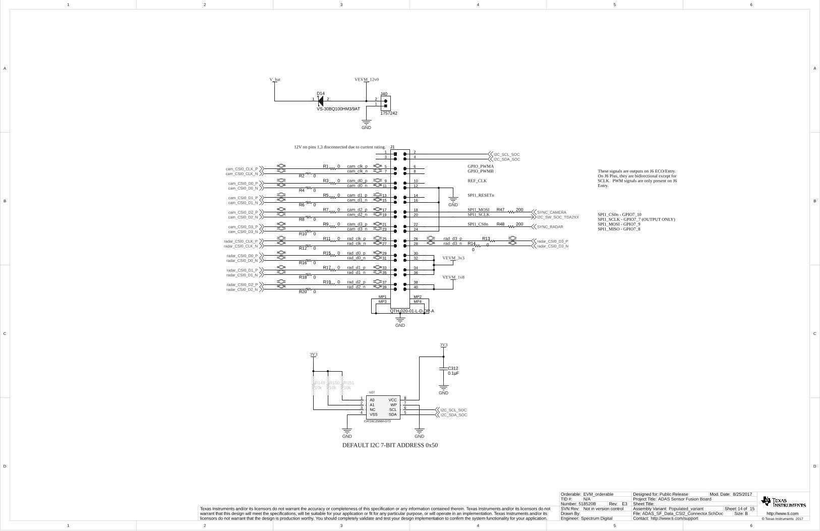
12V on pins 1,3 disconnected due to current rating.
SPI1_CS0n
SPI1_SCLKSPI1_MOSI
SPI1_RESETn
REF_CLK
GPIO_PWMBGPIO_PWMA
SYNC_CAMERA
SYNC_RADAR200R48
0.1µFC312
3V3
GND
GND GND
10kR151
10kR150
10kR149
3V3
I2C_SDA_SOCI2C_SCL_SOC
I2C_SW_SOC_TDA2XX
200R47SPI1_CS0n - GPIO7_10SPI1_SCLK - GPIO7_7 (OUTPUT ONLY)SPI1_MOSI - GPIO7_9SPI1_MISO - GPIO7_8
These signals are outputs on J6 ECO/Entry. On J6 Plus, they are bidirectional except for SCLK. PWM signals are only present on J6 Entry.
A01 VCC 8
VSS4NC3 SCL 6
SDA 5
A12 WP 7
U27
CAT24C256WI-GT3
DEFAULT I2C 7-BIT ADDRESS 0x50
1
1
2
2
3
3
4
4
5
5
6
6
D D
C C
B B
A A
15 15
10/19/2017
ADAS_SF_rev1_Hardware.SchDoc
Sheet Title:
Size:
Mod. Date:
File:Sheet: of
B http://www.ti.comContact: http://www.ti.com/support
ADAS Sensor Fusion BoardProject Title:Designed for: Public Release
Assembly Variant: Populated_variant
© Texas Instruments 2017Drawn By:Engineer: Spectrum Digital
Texas Instruments and/or its licensors do not warrant the accuracy or completeness of this specification or any information contained therein. Texas Instruments and/or its licensors do not warrant that this design will meet the specifications, will be suitable for your application or fit for any particular purpose, or will operate in an implementation. Texas Instruments and/or its licensors do not warrant that the design is production worthy. You should completely validate and test your design implementation to confirm the system functionality for your application.
Not in version controlSVN Rev:518520BNumber: Rev: E3
TID #: N/AOrderable: EVM_orderable
LOGOPCB
Texas Instruments
1
H1NY PMS 440 0025 PH
1
H2NY PMS 440 0025 PH
1
H3NY PMS 440 0025 PH
1
H4NY PMS 440 0025 PH
H5
1902C
H6
1902C
H7
1902C
H8
1902C
FID2FID1 FID3
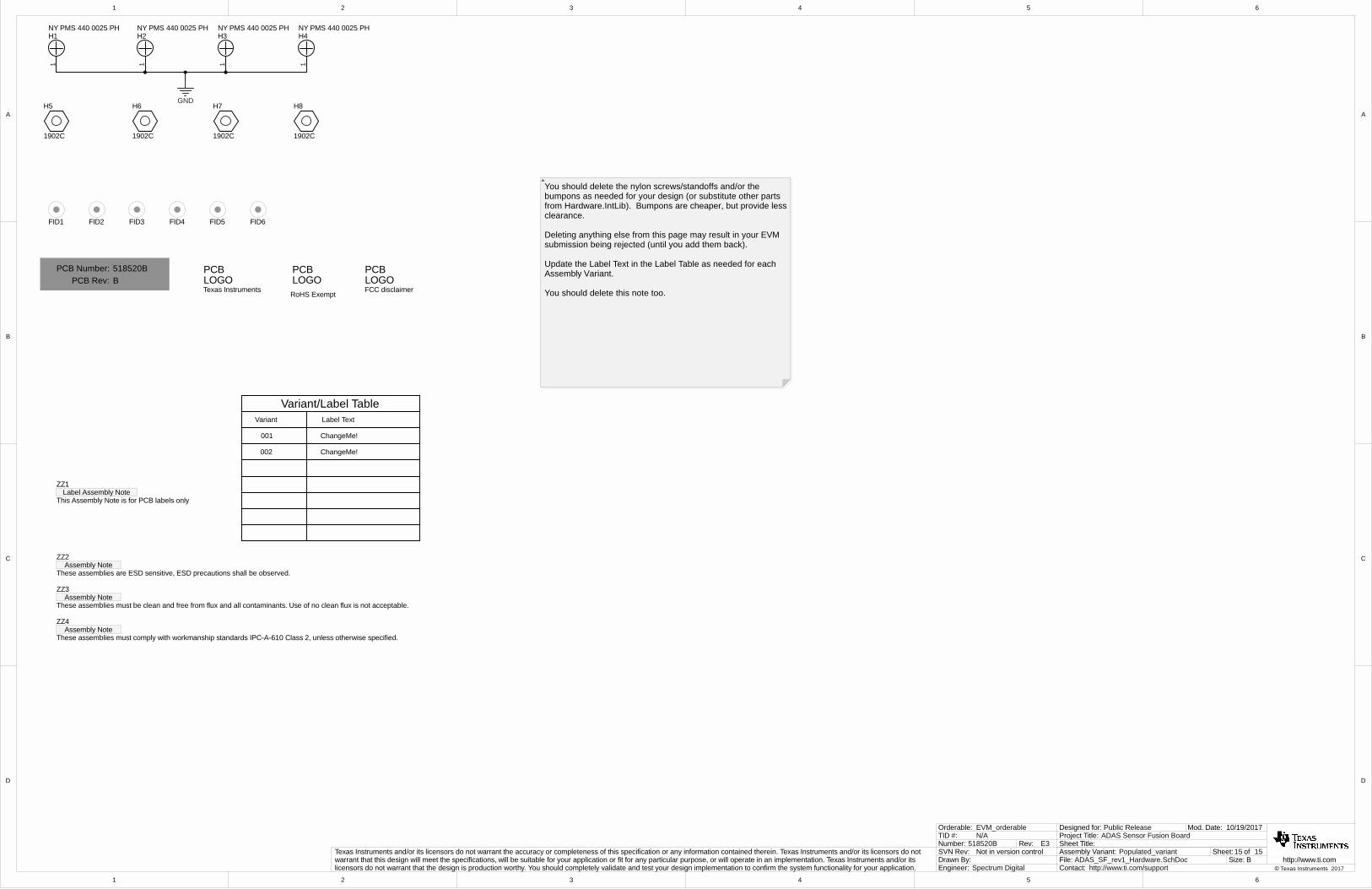
518520BB
PCB Number:PCB Rev:
Label Assembly NoteZZ1
This Assembly Note is for PCB labels only
Assembly NoteZZ2
These assemblies are ESD sensitive, ESD precautions shall be observed.
Assembly NoteZZ3
These assemblies must be clean and free from flux and all contaminants. Use of no clean flux is not acceptable.
Assembly NoteZZ4
These assemblies must comply with workmanship standards IPC-A-610 Class 2, unless otherwise specified.
Variant/Label TableVariant Label Text
001 ChangeMe!
002 ChangeMe!
LOGOPCB
RoHS Exempt
LOGOPCB
FCC disclaimer
FID5FID4 FID6
GND
You should delete the nylon screws/standoffs and/or the bumpons as needed for your design (or substitute other parts from Hardware.IntLib). Bumpons are cheaper, but provide less clearance.
Deleting anything else from this page may result in your EVM submission being rejected (until you add them back).
Update the Label Text in the Label Table as needed for each Assembly Variant.
You should delete this note too.

IMPORTANT NOTICE FOR TI DESIGN INFORMATION AND RESOURCES
Texas Instruments Incorporated (‘TI”) technical, application or other design advice, services or information, including, but not limited to,reference designs and materials relating to evaluation modules, (collectively, “TI Resources”) are intended to assist designers who aredeveloping applications that incorporate TI products; by downloading, accessing or using any particular TI Resource in any way, you(individually or, if you are acting on behalf of a company, your company) agree to use it solely for this purpose and subject to the terms ofthis Notice.TI’s provision of TI Resources does not expand or otherwise alter TI’s applicable published warranties or warranty disclaimers for TIproducts, and no additional obligations or liabilities arise from TI providing such TI Resources. TI reserves the right to make corrections,enhancements, improvements and other changes to its TI Resources.You understand and agree that you remain responsible for using your independent analysis, evaluation and judgment in designing yourapplications and that you have full and exclusive responsibility to assure the safety of your applications and compliance of your applications(and of all TI products used in or for your applications) with all applicable regulations, laws and other applicable requirements. Yourepresent that, with respect to your applications, you have all the necessary expertise to create and implement safeguards that (1)anticipate dangerous consequences of failures, (2) monitor failures and their consequences, and (3) lessen the likelihood of failures thatmight cause harm and take appropriate actions. You agree that prior to using or distributing any applications that include TI products, youwill thoroughly test such applications and the functionality of such TI products as used in such applications. TI has not conducted anytesting other than that specifically described in the published documentation for a particular TI Resource.You are authorized to use, copy and modify any individual TI Resource only in connection with the development of applications that includethe TI product(s) identified in such TI Resource. NO OTHER LICENSE, EXPRESS OR IMPLIED, BY ESTOPPEL OR OTHERWISE TOANY OTHER TI INTELLECTUAL PROPERTY RIGHT, AND NO LICENSE TO ANY TECHNOLOGY OR INTELLECTUAL PROPERTYRIGHT OF TI OR ANY THIRD PARTY IS GRANTED HEREIN, including but not limited to any patent right, copyright, mask work right, orother intellectual property right relating to any combination, machine, or process in which TI products or services are used. Informationregarding or referencing third-party products or services does not constitute a license to use such products or services, or a warranty orendorsement thereof. Use of TI Resources may require a license from a third party under the patents or other intellectual property of thethird party, or a license from TI under the patents or other intellectual property of TI.TI RESOURCES ARE PROVIDED “AS IS” AND WITH ALL FAULTS. TI DISCLAIMS ALL OTHER WARRANTIES ORREPRESENTATIONS, EXPRESS OR IMPLIED, REGARDING TI RESOURCES OR USE THEREOF, INCLUDING BUT NOT LIMITED TOACCURACY OR COMPLETENESS, TITLE, ANY EPIDEMIC FAILURE WARRANTY AND ANY IMPLIED WARRANTIES OFMERCHANTABILITY, FITNESS FOR A PARTICULAR PURPOSE, AND NON-INFRINGEMENT OF ANY THIRD PARTY INTELLECTUALPROPERTY RIGHTS.TI SHALL NOT BE LIABLE FOR AND SHALL NOT DEFEND OR INDEMNIFY YOU AGAINST ANY CLAIM, INCLUDING BUT NOTLIMITED TO ANY INFRINGEMENT CLAIM THAT RELATES TO OR IS BASED ON ANY COMBINATION OF PRODUCTS EVEN IFDESCRIBED IN TI RESOURCES OR OTHERWISE. IN NO EVENT SHALL TI BE LIABLE FOR ANY ACTUAL, DIRECT, SPECIAL,COLLATERAL, INDIRECT, PUNITIVE, INCIDENTAL, CONSEQUENTIAL OR EXEMPLARY DAMAGES IN CONNECTION WITH ORARISING OUT OF TI RESOURCES OR USE THEREOF, AND REGARDLESS OF WHETHER TI HAS BEEN ADVISED OF THEPOSSIBILITY OF SUCH DAMAGES.You agree to fully indemnify TI and its representatives against any damages, costs, losses, and/or liabilities arising out of your non-compliance with the terms and provisions of this Notice.This Notice applies to TI Resources. Additional terms apply to the use and purchase of certain types of materials, TI products and services.These include; without limitation, TI’s standard terms for semiconductor products http://www.ti.com/sc/docs/stdterms.htm), evaluationmodules, and samples (http://www.ti.com/sc/docs/sampterms.htm).
Mailing Address: Texas Instruments, Post Office Box 655303, Dallas, Texas 75265Copyright © 2018, Texas Instruments Incorporated