Embed Size (px)
Citation preview
Feasibility Study of Deep Water Power Cable Systems
Enrico Colombo
CESI S.p.A
Layout of Presentation
• The Study Context, Objectives, Participants • Study Approach & Methodology • Assessments and Findings • Implementation Issues • Industrial Challenges • Potential Criticalities • Conclusion
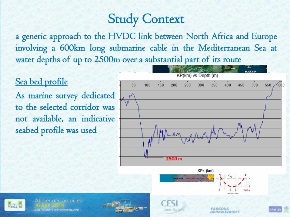
Study Context a generic approach to the HVDC link between North Africa and Europe involving a 600km long submarine cable in the Mediterranean Sea at water depths of up to 2500m over a substantial part of its route
Sea bed profile As marine survey dedicated to the selected corridor was not available, an indicative seabed profile was used
Study Objectives
• identify the environmental, functional, construction and installation context in which a 1000 MW , 600 km long HVDC submarine cable system may develop
• achieve a body of knowledge about the main issues associated with such a context
• investigate the possible choices in terms of design concepts, technology availability, construction capability, laying and repair methods expected to be made available by the ‘market’ for the implementation of the required cable functionalities, in time for commissioning such a new ‘product’ in the target Years 2020 or 2030 on
Study Participants
• The Consulting Team CESI SpA, Intertek, Parsons Brinckerhoff
Cable Manufacturers Innovative Materials Developers Cable Installers Oil & Gas Telecoms Cable Owners Others (manufacturers of buoyancy floats,
cable grips, articulated shells)
• The Stakeholders to validate technical and
economic assumptions or investigate innovative solutions for future application
expectations of availability from the “market” in time for Years 2020 or 2030

Study Approach and Methodology (A&M)
• Technology
• Laying & Protection
• Operation & Maintenance
• Economic Issues
Dedicated Interactive Task Forces
Consultation Process, Market Enquiry
Review of Existing Methods, Projects, R&D Initiatives
Dedicated Questionnaires to the Stakeholders

A&M – Technology : Topics of Concern
• Conductor • Insulation • Lead Sheath • Armour
ability of the amour to withstand the required pulling tension
ability of the cable to withstand 300 bar pressure, salt water/density and to limit water propagation following a possible fault
armour type and material that could be used to reduce weight cable sheath’s friction value and impact on the lay operations
test lab ability to have suitable equipment to undertake required tension test
Pros and Cons of Mass Impregnated non Draining (MIND) vs Cross-Linked Polyethylene (XLPE) o combination of MIND and copper conductor
provides the smallest possible size of insulated conductor
o combination of MIND and aluminium conductor provides the lightest possible insulated conductor
A&M – Technology : Requirements • smallest possible outer diameter – OD to enable a Laying Vessel to
accommodate more single continuing cable length in order to minimise number of joints between campaigns
• lowest possible weight in water • high electric power transmittability • high electrical stress withstandability - in order to reduce insulation
thickness, which subsequently would reduce amount of outer layers of lead sheath and armouring
• capability of withstanding 300bar of water pressure • capability of withstanding tensile strength (pulling tension) while
being laid at the depth of 2500m or while being recovered from the same depth
A&M -Technology : Existing Solutions • examination of different deep sea power cable designs with reference
a 1000 MW bipolar HVDC arrangement in order to identify the physical parameters (dimensions and weight), types and materials of conductor, insulation, sheath and armour.
• identification of the present limits of cable technology and cable laying for a typical deep water and steep slope installation and of the realistic range of exploitable margins obtainable from existing technologies
• industrial best practice related to the conventional submarine HVDC cable technologies deployed at the depths up to 1,600 metres

A&M –Technology : Future Development
• investigation of on-going (2020) and future (2030) development, trends and innovations in submarine HVDC cable industry with reference to design, materials and applications for unusual (up to 2500m) deep sea power cable installation
• examination of a 2500m deep sea power cable design with reference to the physical parameters (dimensions and weight), types and materials of conductor, insulation, sheath and armour, and their relation with the high pressure (up to 300 bar) and mechanical/thermal stress gradient.
• identification of the realistic range of exploitable margins obtainable from existing technologies, anticipating the contribution of technical innovation within the target years

A&M - Laying & Protection : Main Topics
• analysis of availability of suitable marine assets capable of deepwater operations in the target years 2020 such as installation vessels, cable handling equipment and subsea intervention spreads
• identification of the deep water cable installation & recovery methodologies (including adaptations from oil&gas context).

A&M - Laying & Protection : Topics of Concern
• capability of vessel to handle deep water cable lay • cable catenary control • cable touch down monitoring • single vs. bundle lay • very deep marine survey • cable recovery
A&M - Operation & Maintenance : Main Topics
• identification of the most feasible methods for deep water cable maintenance, spares strategy, recovery, monitoring,
• repair fault location and water ingress vessel – size, capacity, availability faulty cable recovery and repair scenarios jointing team availability and experience cables protection
A&M - Economic Issues : Main Topics
• collection and analysis of cost estimates from previous similar experiences/projects
• identification of cost estimate assumptions from a market survey and through contact with selected suppliers and stakeholders
• sensitive analysis of the costs estimate of new cable installations
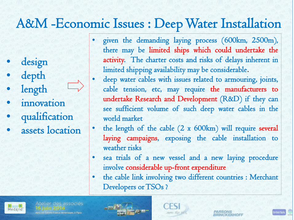
A&M -Economic Issues : Deep Water Installation
• design • depth • length • innovation • qualification • assets location
• given the demanding laying process (600km, 2500m), there may be limited ships which could undertake the activity. The charter costs and risks of delays inherent in limited shipping availability may be considerable.
• deep water cables with issues related to armouring, joints, cable tension, etc, may require the manufacturers to undertake Research and Development (R&D) if they can see sufficient volume of such deep water cables in the world market
• the length of the cable (2 x 600km) will require several laying campaigns, exposing the cable installation to weather risks
• sea trials of a new vessel and a new laying procedure involve considerable up-front expenditure
• the cable link involving two different countries : Merchant Developers or TSOs ?
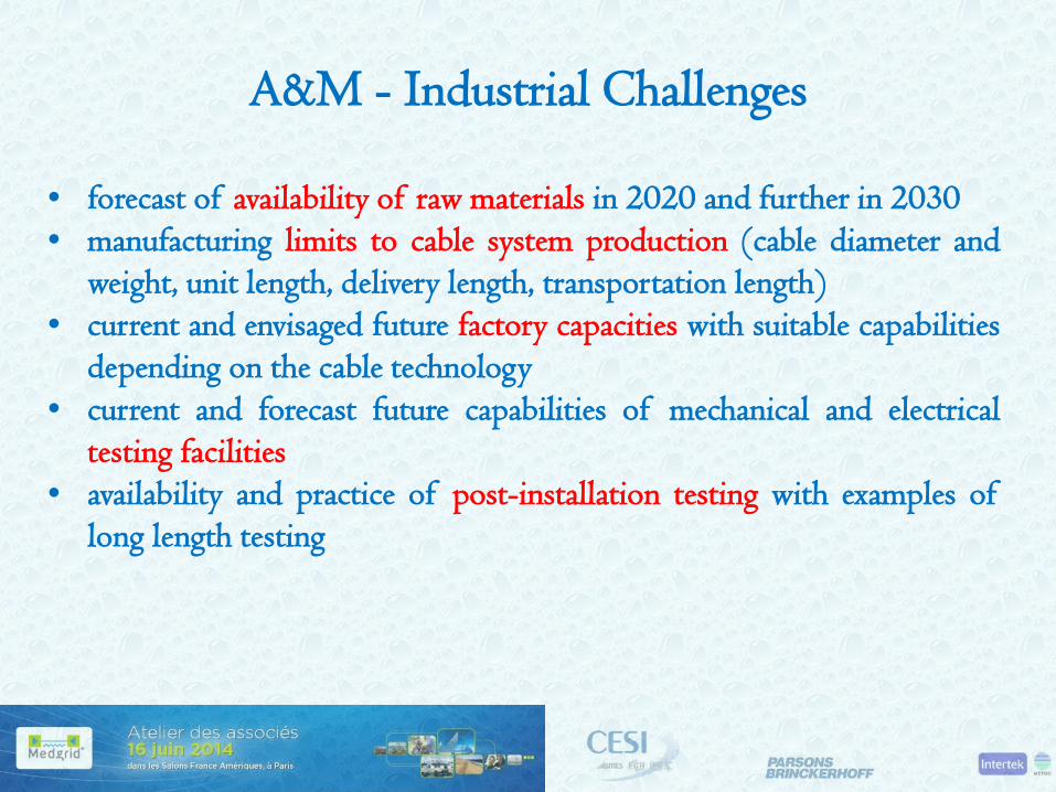
A&M - Industrial Challenges
• forecast of availability of raw materials in 2020 and further in 2030 • manufacturing limits to cable system production (cable diameter and
weight, unit length, delivery length, transportation length) • current and envisaged future factory capacities with suitable capabilities
depending on the cable technology • current and forecast future capabilities of mechanical and electrical
testing facilities • availability and practice of post-installation testing with examples of
long length testing
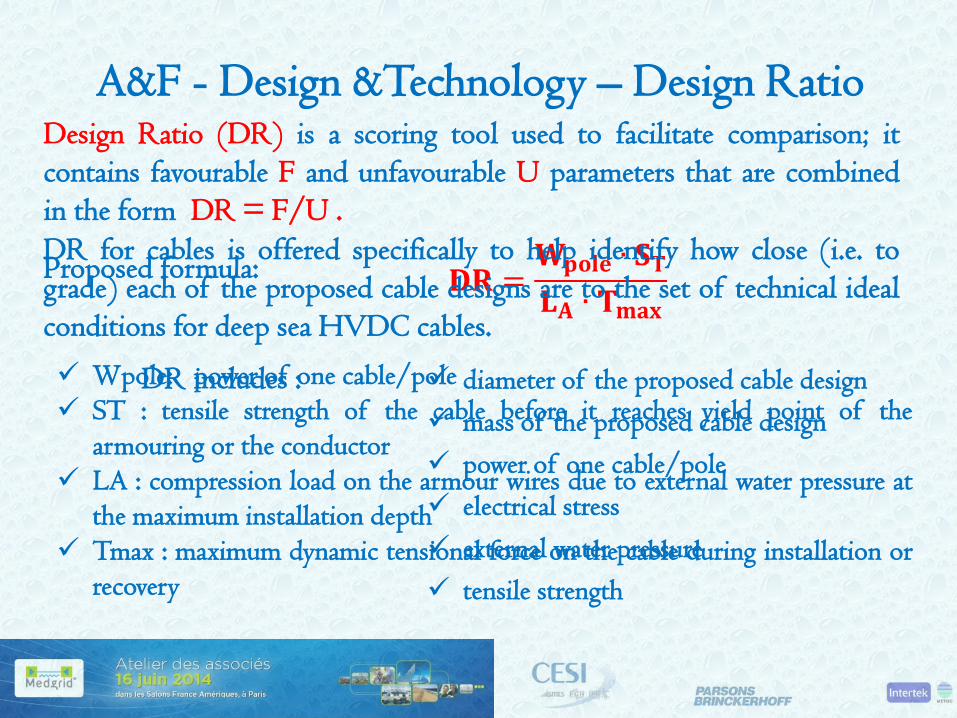
A&F - Design &Technology – Design Ratio Design Ratio (DR) is a scoring tool used to facilitate comparison; it contains favourable F and unfavourable U parameters that are combined in the form DR = F/U .
diameter of the proposed cable design mass of the proposed cable design power of one cable/pole electrical stress external water pressure tensile strength
Proposed formula:
Wpole: power of one cable/pole ST : tensile strength of the cable before it reaches yield point of the
armouring or the conductor LA : compression load on the armour wires due to external water pressure at
the maximum installation depth Tmax : maximum dynamic tensional force on the cable during installation or
recovery
DR includes :
DR for cables is offered specifically to help identify how close (i.e. to grade) each of the proposed cable designs are to the set of technical ideal conditions for deep sea HVDC cables.
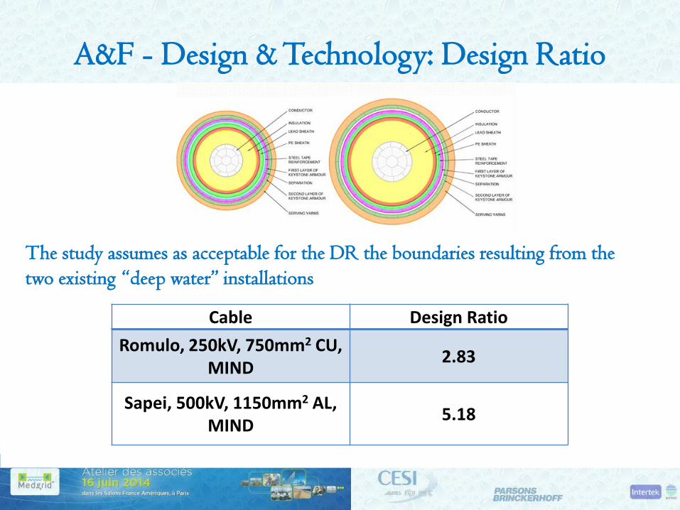
A&F - Design & Technology: Design Ratio
Recent deep sea HVDC cable designs and configurations used in SAPEI and ROMULO projects have become the base for this study :
Project Voltage kV
El. Stress kV/mm
Type of deep sea Cable
Outer Dia mm
Weight in air kg/m
Weight in water kg/m
Design ratio
ROMULO, 2x200MW, Max depth:
1485m
250 30
750mm2 CU keystone
conductor, MIND
94 29.5 22.6 2.83
SAPEI, 2x500MW, Max depth:
1620m
500 30.8
1150mm2 AL keystone
conductor, MIND
119.2 36.1 24.9 5.18 Romulo 250 kV
Sapei 500 kV
The study assumes as acceptable for the DR the boundaries resulting from the two existing “deep water” installations
Cable Design Ratio Romulo, 250kV, 750mm2 CU,
MIND 2.83
Sapei, 500kV, 1150mm2 AL, MIND 5.18

A&F - Cable Laying
• dynamic tensions of 90 – 115 tonnes will be experienced at 2500m depths.
• considering the dynamic tension limits of the largest cable ships currently on the market (55 – 65 tonnes) and those of the flexible pipelay vessels (100 – 550 tonnes), the following installation arrangement is proposed:
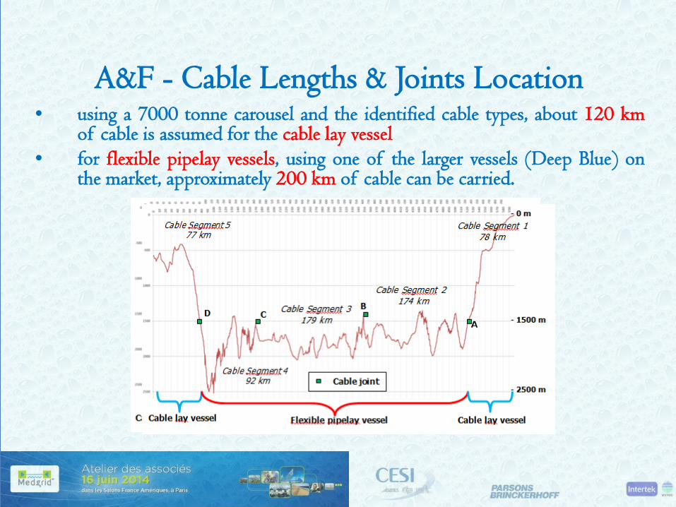
A&F - Cable Lengths & Joints Location • using a 7000 tonne carousel and the identified cable types, about 120 km
of cable is assumed for the cable lay vessel • for flexible pipelay vessels, using one of the larger vessels (Deep Blue) on
the market, approximately 200 km of cable can be carried.
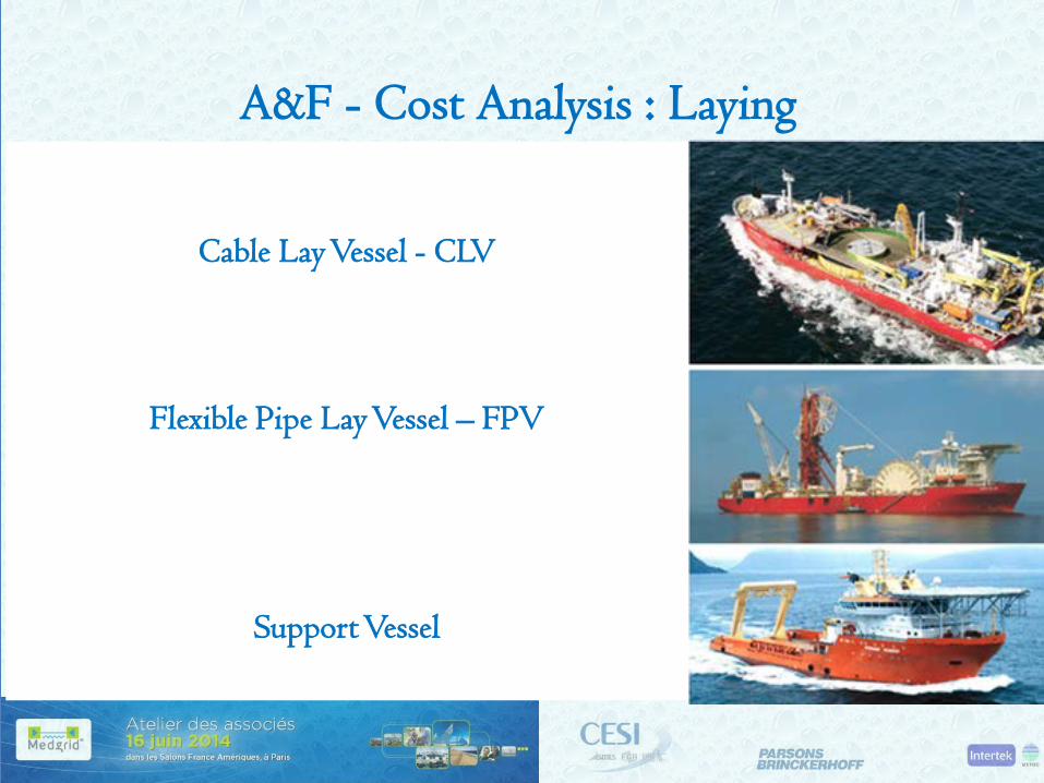
A&F - Cost Analysis : Laying
Vessel Resources to cope with the assumed cable route: 1 x Cable lay vessel (up to 1500 m) 1 x Flexible pipelay vessel (from 1500 – 2500 m) 1 x Support vessel (up to 1000 m) 1 x Guard vessel (up to 1000 m) 1 x Jointing vessel
Cable Lay Vessel - CLV
Flexible Pipe Lay Vessel – FPV
Support Vessel
A&F – O&M
• availability of suitable vessels for repair can be a risk in achieving a rapid repair. It may be that the Owners consider paying a retention fee to guarantee availability of a suitable vessel, within an agreed time frame. The repair vessel may be quite different from the original laying vessel. A new design of ROVs may be required to support repair activities in deep water
• it is advisable that the maintenance policy provides for a maintenance agreement, which aims at achieving priority in providing an independent fleet of vessels with dedicated repair teams on standby 24/7 to their members.
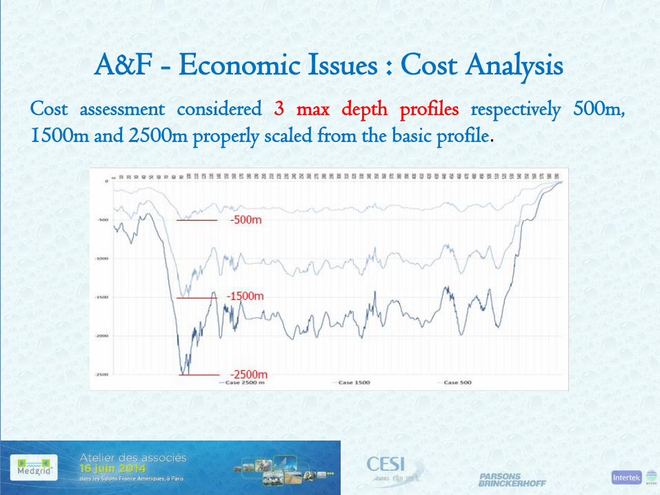
A&F - Economic Issues : Cost Analysis Cost assessment considered 3 max depth profiles respectively 500m, 1500m and 2500m properly scaled from the basic profile.
A&F - Economic Issues : Cost Analysis
Cost Factors evaluated with reference to the cable solutions selected for the three max depth scenarios having the basic 500m max depth at reference (per unit)
Cost Items : Manufacturing Laying Jointing Protection Spares
A&F - Cost Analysis : Manufacturing
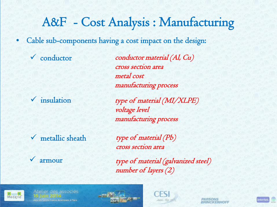
• Cable sub-components having a cost impact on the design:
conductor conductor material (Al, Cu) cross section area metal cost manufacturing process
insulation type of material (MI/XLPE) voltage level manufacturing process
metallic sheath
armour
type of material (Pb) cross section area
type of material (galvanized steel) number of layers (2)

A&F - Cost Analysis : Manufacturing
• for 500m and 1500m max depth the cable design is chosen with reference to the proven design already implemented for said depths
• the identification of the cost sharing among the elementary cost items for the scenarios up to 1500m depth takes into consideration declared costs of actual installations for which final costs were found available (MI)
• for 2500m max depth MI and XLPE cable design are selected

A&F - Cost Analysis : Manufacturing
500 m 1500 m 2500 m DC Voltage Level [kV] 500 500 400 500 Insulation Type MIND MIND XLPE MIND
Insulation Cost Factor 1 1.04 0.71 1.04 Conductor material Cu Al Al Al Conductor Section [mm2] 1000 1150 1400 1150
Conductor Cost Factor 1 0.48 0.55 0.48 Sheath Material Pb Pb Pb Pb Cross section area [mm2] 727 751 837 866
Sheath Cost Factor 1 1.03 1.15 1.19 Armour Material Galvan. Steel Galvan. Steel Galvan. Steel Galvan. Steel Number of Layer 2 2 2 2 Cross section area [mm2] 683 1830 2730 3190
Armour Cost Factor 1 2.67 4.0 4.67
Manufact. Cost Factor 1 0.98 0.87 1.10
Insulation: the cost factor for XLPE results lower compared with that of the MI solution due to the cheaper manufacturing process. The cost resulting for the 1,500 m scenario is slightly higher due to the higher diameter of the conductor
Conductor: the cost for the 1500m and 500m scenarios which are assumed made of aluminium are lower due to the lower cost of this material compared with copper
Sheath: the cost of the sheath has been evaluated starting from the values of cross section area and hence from the weight of Pb relevant to the characteristics of the cables. The cost factor is hence proportional to the cross section area
Armour: a higher cost for the 2500m depth results as the design should ensure withstand of a higher tension load during laying. Also in this case the cost factor has been estimated under the assumption of proportionality with the cross section area
The total cost factor of the cables is mainly affected by the insulation and conductor costs that represent the biggest part of the manufacturing cost

A&F - Cost Analysis : Manufacturing
the Cable Manufacturing Cost Factor is assessed applying an “Innovation Factor” estimated considering the additional effort required to cope with the mechanical aspects related with the very high depth.
500m - MI 1500m -MI 2500m-XLPE 2500m-MI
Innovation Factor 1 1.1 1.4 1.2 Cost Factor 1 1.08 1.22 1.32
A&F - Cost Analysis : Laying
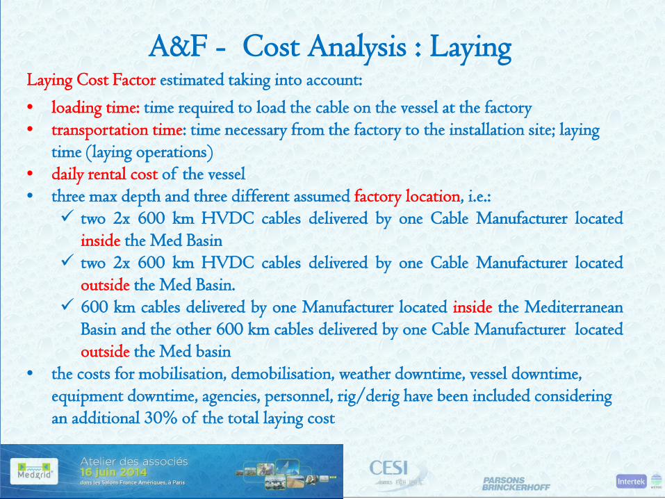
Laying Cost Factor estimated taking into account:
• loading time: time required to load the cable on the vessel at the factory • transportation time: time necessary from the factory to the installation site; laying
time (laying operations) • daily rental cost of the vessel • three max depth and three different assumed factory location, i.e.:
two 2x 600 km HVDC cables delivered by one Cable Manufacturer located inside the Med Basin
two 2x 600 km HVDC cables delivered by one Cable Manufacturer located outside the Med Basin.
600 km cables delivered by one Manufacturer located inside the Mediterranean Basin and the other 600 km cables delivered by one Cable Manufacturer located outside the Med basin
• the costs for mobilisation, demobilisation, weather downtime, vessel downtime, equipment downtime, agencies, personnel, rig/derig have been included considering an additional 30% of the total laying cost
A&F - Cost Analysis : Laying
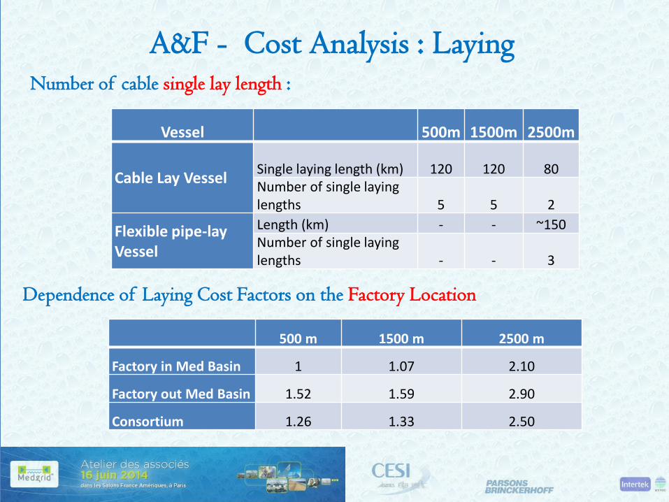
Number of cable single lay length :
Vessel 500m 1500m 2500m
Cable Lay Vessel Single laying length (km) 120 120 80 Number of single laying lengths 5 5 2
Flexible pipe-lay Vessel
Length (km) - - ~150 Number of single laying lengths - - 3
Dependence of Laying Cost Factors on the Factory Location
500 m 1500 m 2500 m
Factory in Med Basin 1 1.07 2.10
Factory out Med Basin 1.52 1.59 2.90
Consortium 1.26 1.33 2.50

A&F - Cost Analysis : Protection
• protection limit : assumed at 1000m depth

A&F - Cost Analysis : Protection
• Type of protection and protection breakdown
* part of the route near the shore present a higher probability to be featured by hard seabed for which trenching may be required
500m 1500m 2500m Ploughing [%] 35% 15% 15% Jetting [%] 35% 15% 15% Trenching [%] * 25% 65% 65%
Remedial Protection [%] 5% 5% 5%
• Cable Protection Cost Factor
500m 1500m 2500m
1 0.83 0.45
A&F - Cost Analysis : Jointing
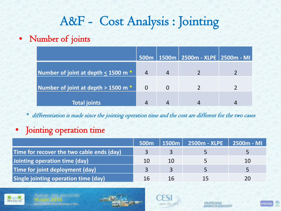
• Number of joints
500m 1500m 2500m - XLPE 2500m - MI
Number of joint at depth < 1500 m * 4 4 2 2
Number of joint at depth > 1500 m * 0 0 2 2
Total joints 4 4 4 4
* differentiation is made since the jointing operation time and the cost are different for the two cases
• Jointing operation time 500m 1500m 2500m - XLPE 2500m - MI
Time for recover the two cable ends (day) 3 3 5 5 Jointing operation time (day) 10 10 5 10 Time for joint deployment (day) 3 3 5 5 Single jointing operation time (day) 16 16 15 20
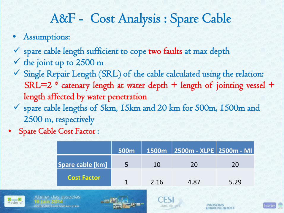
A&F - Cost Analysis : Spare Cable
• Assumptions:
spare cable length sufficient to cope two faults at max depth the joint up to 2500 m Single Repair Length (SRL) of the cable calculated using the relation: SRL=2 * catenary length at water depth + length of jointing vessel +
length affected by water penetration spare cable lengths of 5km, 15km and 20 km for 500m, 1500m and
2500 m, respectively • Spare Cable Cost Factor :
500m 1500m 2500m - XLPE 2500m - MI
Spare cable [km] 5 10 20 20
Cost Factor 1 2.16 4.87 5.29
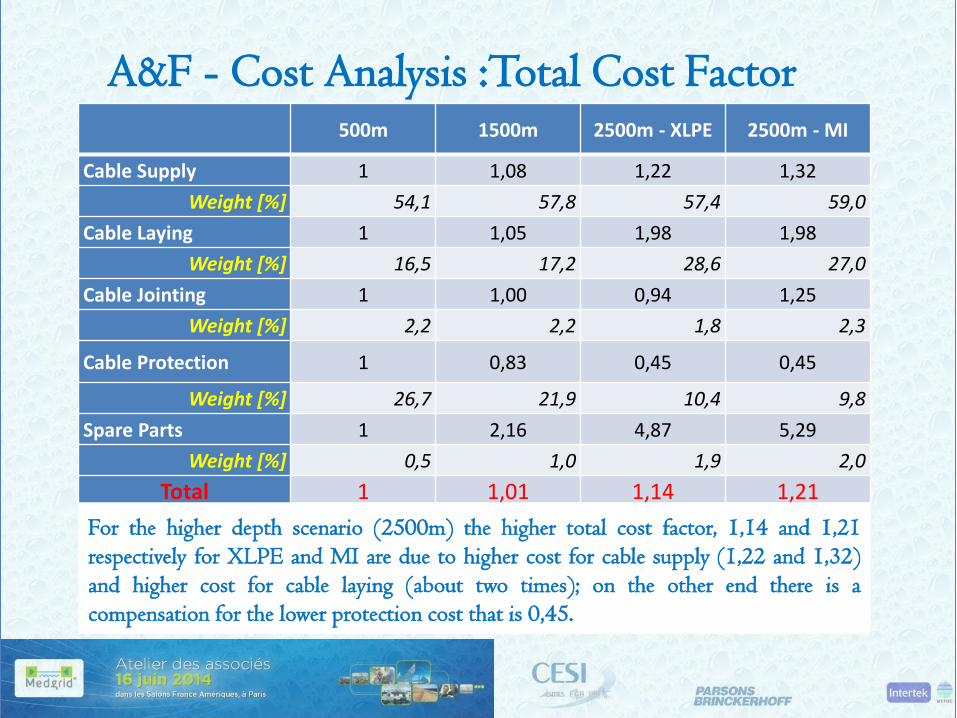
A&F - Cost Analysis :Total Cost Factor
500m 1500m 2500m - XLPE 2500m - MI
Cable Supply 1 1,08 1,22 1,32 Weight [%] 54,1 57,8 57,4 59,0
Cable Laying 1 1,05 1,98 1,98 Weight [%] 16,5 17,2 28,6 27,0
Cable Jointing 1 1,00 0,94 1,25 Weight [%] 2,2 2,2 1,8 2,3
Cable Protection 1 0,83 0,45 0,45
Weight [%] 26,7 21,9 10,4 9,8 Spare Parts 1 2,16 4,87 5,29
Weight [%] 0,5 1,0 1,9 2,0 Total 1 1,01 1,14 1,21
The cost relative to the 1500m max depth scenario is similar to the reference case (500 m) because the higher cost for cable supply is compensate by a lower protection cost. The cost factor of 2,16÷5,29 of the spare parts has a small impact due to the lower impact on total cost (0,5÷2%).
For the higher depth scenario (2500m) the higher total cost factor, 1,14 and 1,21 respectively for XLPE and MI are due to higher cost for cable supply (1,22 and 1,32) and higher cost for cable laying (about two times); on the other end there is a compensation for the lower protection cost that is 0,45.

A&F - Project Implementation
To procure the complete bi-pole, following the contract award, it will take approximately 8* or 10** years broken down as follows: pre-tender activities: about 2 years pre-qualification activities: 1.7 years project implementation: 5* or 7* year engineering and detailed marine survey: 1.25 year cable manufacturing: 3* or 5* years installation: 1.5* or 3.4* years commissioning: 0.3 year * depending on the number and capacity of production lines engaged
10 years 8 years

Industrial Challenges
different types of competing projects may have the potential to cause delays as they may require the engagement of same installation resources e.g. cable lay, construction vessels, ROVs, etc.
some 30 projects may be identified that may have an impact to the Year 2020 scenario and 12 projects to the 2030 one.
Industrial Challenges • availability of suitable equipment, innovative methods, techniques and
materials across HVDC submarine cable industry to supply, install a complete deep sea HVDC cable system of 1000MW , 600km length with deep water sections up to 2500 metres.
• manufacturing slots and lead times for HVDC converter stations, cable systems, tools and equipment. Possibility of signing multi-vendor contracts for HVDC cable systems and converter stations in order to reduce lead times
• forecast of growing demand for power cables, particularly for HVDC deep sea submarine systems, and availability of credible manufacturers, suitable testing facilities (electrical and mechanical), cable installation vessels designed specifically for deep sea power cable installation and trained and qualified crews
Industrial Challenges
• availability of specialised equipment, toolings for deep water cable laying
• current vessel market : conversion of deep water oil&gas equipment • future availability of deep water ROVs for installation and emergency
repairs
to consider that as for the above aspects there is no established and acknowledged procedure for their qualification
Challenging topics expected to be launched within the context of the marine assets at the expected time frame (2020/2030)

Topics of Potential Criticality • Advanced bookings
materials and manufacture slot bookings would probably need to occur well in advance (4 years) ahead of manufacture because the XLPE cable market is so buoyant, and predicted to get even busier. For MI cable, the same issue arises, though not quite as severely as for XLPE.
“Front-end-engineering”, “Seabed survey and routeing”, “Licensing, permits and wayleaves” tasks would all count towards the booking-ahead period.
• Marine survey (desk-top and physical aspects) its schedule cannot be brought forward significantly to the start of the project until the survey and analysis is complete, it is difficult to provide specific
information for the licensing, permits and wayleaves processes. These licensing and similar processes are, in turn, also critical because until they are complete, it would be inappropriate to commit to the major cable production and installation contracts
Summary
• Technology MI and XLPE/extruded insulation technology equally acceptable MI solution for the near future (2020) being the technology
considered to be better proven for high depths XLPE becomes a priority for near future should the foreseen
reduction in MI cable production availability be confirmed for new Projects and the increasingly proven technology of XLPE insulated cables and accessories expected by that date.
500 kV XLPE insulated for the more distant future (2030) envisaging material technology advances
• Laying 1 x Cable Lay Vessel (up to 1500m) 1 x Flexible Pipelay Vessel (from 1500 – 2500m)

Conclusion
The study was able to identify design, technological, installation and cost solutions for considering the feasibility of a submarine cable 600 km long with a depth of up to 2500m in HVDC bipolar configuration.
This ambitious goal will have to see together actors from the different industrial contexts who will be called to contribute to the implementation of the link in the expected timetable (Year 2020 or 2030), overcoming the potential criticalities. From the contacts made with the potential Stakeholders during the development of the study and the willing shown in providing also confidential data, we can be confident of the consistency of the term "feasible".
Thank You for Your Attention