Embed Size (px)
Citation preview
DECODE
Multi-standard modem IDM 50B User Manual v1.2n
http://www.decode.co.yu

1. INTRODUCTION
1.1 Modem Overview IDM50B is a multistandard modem for asynchronous or transparent data transmission in 300-3400 Hz voice band. For lower baud rates it uses binary frequency modulation techniques (FSK), which make it highly immune to interference and noise and permit extensive voice-band communication link utilization. For higher baud rates it uses QAM modulations with 4, 8 and 16 constelation points, depending of selected rate.
The modem supports CCITT V.29, R.38A, R.38B, R.37, R.35, V.23 and Cegelec 1200/600Bd communication standards. Table of programmable channels (Figure 1.) depicts possible utilization of audio band in FSK mode. In FSK mode the modem can operate in half or full-duplex, point-to-point or point-to-multipoint mode, with receive and transmit channels independently set. For V.29 mode, four-wire full/half duplex is default.
The modem employs advanced Texas Instruments 32-bit DSP technology, thus offering high service flexibility through programmable features. Modem configuration is performed via Hayes AT commands on separate DIAG serial port, available at front panel. AT commands may be initiated from any asynchronous terminal application using RS-232 communication interface. Additionally, for easy firmware upgrade, a bootstrap loader is provided using the same DIAG serial port.
IDM50B is designed to be use in SCADA systems mainly based upon power utility communication networks. Depending on selected mode, it can communicate through specialized, private or leased lines, radio links and power lines (PLC).
Figure 1. Table of programmable channels in FSK mode
1.2 Mounting Types IDM50B is available as a desktop modem or in two different types of standard 19'' rack: 1U rack with 1, 2 or 3 modems per rack; 3U rack with 10,12 or 14 modems per rack,
and additional blank front plates covering unused slots. All connectors at the rear side are accessible at the back openings. Please refer to Appendix A for details.
IDM50B User Manual v1.2n, Rev. date: 24 februar, 2009 2

2. INTERFACES
2.1 Front Panel RST Reset button is accessible on the front panel using a pin of diameter under 2 mm (pencil
tip, etc.). It re-initialise all modem functions. The modem must be reset immediately on inconsistent operation appearance, before starting the maintenance diagnosis phase. This reset, like a long duration power cut-off, has no effect on the status of configurations previously loaded into the modem.
SET Set button is used for entering command mode (see “Entering Command Mode” section), which allows modem configuration.
PWR In data mode PWR LED is ON when modem is power supplied and in proper function; PWR LED is OFF in case of: power supply is not present or modem is in malfunction. PWR LED blinks slowly (100ms / 1sec cycle) as an indication of command mode. PWR LED blinks fast (100ms / 100ms cycle) when modem has locally initiated some of the test modes. PWR LED blinks slowly (1sec / 1sec cycle) when modem is remotely brought to some of the test modes.
TXD Transmit LED indicates data transmitted on TXD pin of RS-232 interface.
RTS Request to Send LED indicates state of RTS pin of RS-232 interface.
RXD Receive LED indicates data received on RXD pin of RS-232 interface.
DCD Data Carrier Detect LED indicates the presence of in-channel carrier with level higher then predefined receive level.
Figure 2. IDM 50B Front panel view (desktop version)
2.1.1 DIAG – Command/Bootloader serial interface This connector is a RJ45 8 pin female type connector. It provides the interface between the modem and terminal unit in command mode and in firmware upgrade process. The following table gives the allocation and function of each pin.
PIN ABB. FUNCTION DIRECTION
DTE-DCE 1 SW - BSL Switch – Bootloader selection input x 2 GND Signal Ground - 3 CTS Clear To Send ← 4 RD Received Data ← 5 TD Transmitted Data → 6 RTS Request To Send → 7 SW - RUN Switch – Run selection input x 8 SW - COM Switch – selection output x
IDM50B User Manual v1.2n, Rev. date: 24 februar, 2009 3

2.2 Rear panel connectors Three connectors are placed at the modem’s rear side (Fig. 3).
Figure 3. IDM 50B rear side (desktop version)
2.2.1 RS-232C / Data serial interface This connector is a SUB D 9 pin female type connector with screw locking. It provides the interface between the modem and remote terminal unit or data processing equipment in data mode. The following table gives the allocation and function of each pin.
PIN ABB. FUNCTION DIRECTION
DTE-DCE 1 DCD Data Carrier Detect ← 2 RD Received Data ← 3 TD Transmitted Data → 4 DTR Data Terminal Ready → 5 SG Signal Ground - 6 DSR Data Set Ready ← 7 RTS Request To Send → 8 CTS Clear To Send ← 9 RI Ring Indicator ←
IDM50B User Manual v1.2n, Rev. date: 24 februar, 2009 4

2.2.2 Line / Analog interface
This connector is a SUB D 15 pin female type connector with screw locking, which provides:
Interface between 2 or 4 wire analog line and the modem; The fail relay output
On the same connector modem has interface intended for communications management with a radio interface (squelch and alternate) which are not supported in current firmware version. Figure below depicts analog line interface.
Figure 4. Analog line interface
2.2.4 Power / Power Supply
Power supply connector is a 2-position screw plug type (for 2-2.5 2mm wire) used for connecting the modem to a DC power supply. Polarity is irrelevant. Maximum consumption is 3VA. Table of possible voltage options are shown below.
Option Nominal
Voltage (V)
Voltage Range (V)
DC/DC converter on board
IDM50B - 12 12 9-18V SCW03A-05 IDM50B - 24 24 18-36V SCW03B-05 IDM50B - 48 48 36-72V SCW03C-05
IDM50B User Manual v1.2n, Rev. date: 24 februar, 2009 5

3. HARDWARE CONFIGURATION Hardware configuration is performed directly on the modem board by positioning the jumpers according to the figure and the table below:
Figure 5. Jumper placement on the modem board
3.1 Jumpers placement (bold fase denotes factory default placement)
Feature Jumpers Option (ref. to AT&Mx command) Jumpers Placement
4-wire JP400, JP403 2-3 2/4-wire analog line
JP400, JP403
2-wire (only in FSK/MUX1 or FSK/MUX2 mode)
JP400, JP403 1-2
JP405, JP406 1-2 4-wire (FSK and V.29 mode)
Z input 600Ω, Z output 600Ω JP401, JP402 2-3
JP405 1-2 4-wire (FSK/ MUX1 mode)
Z input 10kΩ Z output 600Ω JP401, JP402, JP406 2-3
JP402 1-2 Z input 600Ω, Z output 10kΩ JP401, JP405, JP406 2-3
4-wire (FSK/ MUX2 mode) Z input 10kΩ,
Z output 10kΩ JP401, JP402, JP405, JP406
2-3
JP405 1-2 2-wire (FSK/ MUX1 mode)
Z = 600Ω JP401, JP402, JP406 2-3
Input & Output Impedance
JP401, JP402, JP405, JP406
2-wire (FSK/ MUX2 mode)
Z = 10kΩ JP401, JP402, JP405, JP406
2-3
Transmitter 3-state control off 1-2 Transmitter 3-state control
JP404 Transmitter 3-state control on
JP404 2-3
IDM50B User Manual v1.2n, Rev. date: 24 februar, 2009 6

Feature Jumpers Option Jumpers Placement
JP407 ON Proceed alternate radio relay signals ALT1 and ALT2 to connector JP409 ON
JP407 OFF
Alternate radio relay signal presence on connector
JP407, JP409
Do not proceed alternate radio relay signals ALT1 and ALT2 to connector JP409 OFF
JP411 ON Proceed fail relay signals DEF1 and DEF2 to connector JP412 ON
JP411 OFF
Fail relay signal presence on connector
JP411, JP412
Do not proceed fail relay signals DEF1 and DEF2 to connector JP412 OFF
JP408 ON Proceed the alternate squelch data signals SQ+ and SQ- to connector JP410 ON
JP408 OFF
Squelch data signal presence on connector
JP408, JP410
Do not proceed squelch data signals SQ+ and SQ- to connector JP410 OFF Enabled by switch on adapter cable 1-2 Bootstrap loader
operation JP300
Enabled JP300
2-3
IDM50B User Manual v1.2n, Rev. date: 24 februar, 2009 7
4. SOFTWARE CONFIGURATION 4.1 Introduction to AT Commands
A command line is a string of characters sent from a DTE to the modem (DCE) while the modem is in command mode. A command line has a prefix, a body, and a terminator. Each command line must begin with the AT character sequence and must be terminated by a carriage return. Commands entered in upper or lower case are accepted, but no combination is allowed. Characters that precede the AT prefix are ignored. The AT command body contains printable ASCII characters (32-126). The terminator is ASCII <CR> character. The command line interpretation begins upon receipt of the carriage return character. Empty AT command containing no characters but AT and <CR> is used as an indication that modem is in command state and works correctly. Modem answers with <CR><LF>OK<CR><LF>. <CR> and <LF> are control characters that precede and follow every modem response message, so they will be omitted in following text. The modem recognizes a backspace character (ASCII 08) after AT sequence. It clears previously typed character from modem command buffer, allowing correction of wrong entered command with no consequence. If syntax error, invalid range or nonexistent command is detected in entered command line, modem responds with “ERROR” message. Entered command is accepted only if previous AT command is executed and acknowledged with corresponding message. Advice: Since modem doesn’t support character echoing in command mode, it is
advised to activate local echo in terminal application (Telix, HyperTerminal, etc.) used for AT setting. Local echo will help to insure which characters were typed and sent to modem.
4.2 Entering Command Mode By default, modem is in data mode. In data mode modem performs its basic function transmitting data over preset channels. While modem is in data mode it is not allowed to perform any setting procedures. To enter command mode perform following procedure:
1. Connect the communication cable to DIAG RS-232 connector at the modem front panel. Data transmission and configuration are performed over the different ports. The configuration adapter is used for firmware boot loading only.
2. a) If modem is turned off, push the SET button, turn on the modem by connecting its power supply and keep the SET button pushed approximately for 1 second. b) If modem is already turned on, push the SET button, then push and release the RESET button while keeping the SET button pushed approximately for 1 second.
3. Modem will respond with its introductory message “IDM 50B LS vx.x” indicating command mode and firmware version.
Important: For proper modem configuration 8N1data format at 1200b/s needs to be selected in terminal application.
IDM50B User Manual v1.2n, Rev. date: 24 februar, 2009 8

4.3 Commands Description
Operational Mode AT&Mx Sets FSK or CCITT V.29 operational modes. Valid values for x are:
x = 0 FSK mode where Zin/out=600Ω x = 1 FSK/MUX1 mode where Zin=10k and Zout=600Ω x = 2 FSK/MUX2 mode where Zin=600Ω/10k and Zout=10k x = 3 V.29 mode, 4800bps x = 4 V.29 mode, 7200bps x = 5 V.29 mode, 9600bps
Example: AT&M5 command line sets 9600bps V.29 mode. Modem responds with “OK” message.
Transmit Channel in FSK mode
AT&TC23/y Sets CCITT V.23/1 and V.23/2 channels for data transmission. Valid range for y is 0, 1 and 2 corresponding to V.23/0 and V.23/1 at 600Bd, and V.23/2 at 1200Bd channels, respectively.
AT&TC701 Sets Cegelec 1200Bd 701 channel for data transmission.
AT&TC60x Sets Cegelec 600Bd 60x channels for data transmission. Valid range for x is 1-3, corresponding to channels 601 to 603.
AT&TC40x/y Sets CCITT R.38A 200/300Bd channels for data transmission. Valid range for x is 1-7, corresponding to channels 401 to 407; valid range for y is 1, 2 corresponding to 200, 300Bd channels baud rate, respectively.
AT&TC30x Sets CCITT R.38B 200Bd channels for data transmission. Valid range for x is 1-8, corresponding to channels 301 to 308.
AT&TC2xx Sets CCITT R.37 100Bd channels for data transmission. Valid range for xx is 01-12, corresponding to channels 201 to 212.
AT&TC1xx Sets CCITT R.35 50Bd channels for data transmission. Valid range for
xx is 01-24, corresponding to channels 101 to 124.
Example: AT&TC402/2 command line sets channel 402 at 300Bd data rate for data transmission. Modem responds with “OK” message.
IDM50B User Manual v1.2n, Rev. date: 24 februar, 2009 9

Receive Channel in FSK mode AT&RC23/y Sets CCITT V.23/1 and V.23/2 channels for data reception. Valid
range for y is 1, 2 corresponding to V23/0 and V.23/1 at 600Bd, and V.23/2 at 1200Bd channels, respectively.
AT&RC701 Sets Cegelec 1200Bd 701 channel for data reception.
AT&RC60x Sets Cegelec 600Bd 60x channels for data reception. Valid range for x is 1-3, corresponding to channels 601 to 603.
AT&RC40x/y Sets CCITT R.38A 200/300Bd channels for data reception. Valid range for x is 1-6, corresponding to channels 401 to 407; valid range for y is 1, 2 corresponding to 200, 300Bd channels baud rate, respectively.
AT&RC30x Sets CCITT R.38B 200Bd channels for data reception. Valid range for x is 1-8, corresponding to channels 301 to 308.
AT&RC2xx Sets CCITT R.37 100Bd channels for data transmission. Valid range for xx is 01-12, corresponding to channels 201 to 212.
AT&RC1xx Sets CCITT R.35 50Bd channels for data transmission. Valid range for
xx is 01-24, corresponding to channels 101 to 124.
Example: AT&RC123 command line sets channel 123 at 50Bd data rate for data reception. Modem responds with “OK” message.
Reverse FSK frequencies
AT&RFx Sets frequencies order in FSK modes. When set to "0" then normal FSK frequencies order are set and -F corresponds to data line SPACE condition and +F corresponds to data line MARK condition. When set to "1" then reverse FSK frequencies order are set and -F corresponds to data line MARK condition and +F corresponds to data line SPACE condition. If invalid range is entered, modem responds with “ERROR” message, otherwise responds with “OK” message.
Example: AT&RF0 command line sets normal FSK frequencies order. Modem responds with “OK” message.
Transmit Level
AT&TLxx Sets transmission level in dBm units in 1dB steps. Valid range for FSK is 0 to 32, corresponding to 0dBm to -32dBm, except in FSK/MUX2 mode where range is 06 to 32, corresponding to -6dBm to -32dBm. If invalid range is entered, modem responds with “ERROR” message, otherwise responds with “OK” message.
Notice: Transmit level is referred to loaded output.
Example: AT&TL8 command line sets –8dBm transmit level. Modem responds with “OK” message.
Receive Level AT&RLxx Sets receive level in dBm units in FSK mode. In V.29 mode receive
level is fixed to R = -26dBm and this settings is ignored. For FSK mode received level R is adjustable by step of 1dB in range from 0 to –36 dBm. Signal is detected at R – 9 dB or grater; signal loss is detected at R - 12 dB or lower. Detection limit is at R – 12 dB (loss of
IDM50B User Manual v1.2n, Rev. date: 24 februar, 2009 10
carrier and DCD signal) with a hysteresis of 3 dB (detection of carrier and DCD signal at R – 9 dB). The minimum reception level is –48 dBm.
Example: AT&RL27 command line sets receive level at –27dBm. Modem responds with “OK” message.
Serial Interface Mode AT&SIx Sets serial interface mode. Valid values for x are 0 to 6. In transparent
data mode with x=0, adjusting carrier control to DOX mode is invalid.
x = 0 Transparent data, no buffering x = 1 Asynchronous data, with buffering x = 2 Indactic Master, bit-synchronous data, no buffering x = 3 Indactic Slave, bit-synchronous data, no buffering x = 4 Indactic Master, asynchronous data, buffering x = 5 Indactic Slave, asynchronous data, buffering x = 6 ITU-R M.493-11 asynchonous data, buffering
Example: AT&SI1 command line sets serial interface to asynchronous mode. Modem responds with “OK” message.
RTS/CTS Delay AT&CTSxxxx Sets delay between Request to Send (RTS) from the DTE and
confirmation by the modem in the form of Clear to Send (CTS). Valid range is 40-6825ms.
Example: AT&CTS50 command line sets RTS/CTS delay at 50ms. Modem responds with “OK” message.
Fail If DCD Off
AT&DCDx Turns on /off “Fail if DCD off” option. For x = 0 modem FAIL relay doesn’t react on DCD changes. For x = 1 FAIL relay is switched on when DCD = 0. CD led on the modem front side follows DCD changes.
PTT When TX On AT&PTTx Turns on /off “PTT When TX On” option. For x = 0 modem PTT
relay doesn’t react on carrier On/Off changes. For x = 1 PTT relay is switched On when carrier is On, and switched Off when carrier if Off. This relay may be used to turn On external transmission equipment (for example radio trasmitters).
Use SQ Input AT&SQx Turns on /off “Use SQ Input” option. For x = 0 modem DCD (CD on
RS-232C and front panel LE diode) follows in-channel carrier presence changes. For x = 1 modem DCD (CD on RS-232C and front panel LE diode) follows SQ input state changes. SQ input may be used for indication of in-channel carrier presence signalization when external reception equipment is used (ex. radio receivers).
Use DTR AT&DTRx Turns on /off “Use DTR” option. For x = 0 state of DTR input is
overriden and assumed that is always set to 1. For x = 1 DSR signal is copied to DTR signal. Modem works properly only when DTR = 1.
IDM50B User Manual v1.2n, Rev. date: 24 februar, 2009 11

Carrier control
AT&CCx Selects transmission carrier control mode. For x=0 transmission is always on and carrier is permanent. For x = 1 transmission is active only if RTS = 1 (Data Terminal Equipment requires to send). For x = 2 transmission is active only if there is data in transmission buffer. This mode is called DOX - Data Operated Xmission.
Important: If half-duplex mode is configured, it is obligatory to set “Transmission on RTS” or DOX option. Otherwise, modem would permanently transmit on a half-duplex line, disabling line access to other modems connected to it.
Character Format
AT&CFdps Selects the number of data bits, parity and stop bits. Valid range for data bits is 5 to 8; for parity is N(one), E(ven), O(dd); for stop bits is 1 or 2. For FSK modulations due to restrictions associated with logic regeneration in asynchronous mode, the modem uses resynchronisation procedure at reception. In this mode the character format is between 5 and 9 useful bits, enclosed with 1 start and 1 stop bit. The parity bit, and additional stop bit is considered as a data bit and will be transmitted without processing, therefore for example, transmission and reception of 9N1 format is possible with FSK modulations with 8E1 or 8O1 settings.
Example: AT&CF8N1 command line sets format: 1 start / 8 data / 1 stop bit. Modem responds with “OK” message.
Display Configuration
AT&V Displays current modem configuration in following form:
Example: AT&V
OPERATING MODE: FSK TX CHANNEL: V.23/1200Bd TX LEVEL: -9dB RTS/CTS DELAY: 50ms RX CHANNEL: V.23/1200Bd RX LEVEL: -15dB REVERSE FSK: NO FAIL IF DCD OFF: NO PTT WHEN TX ON: NO USE SQ INPUT: NO USE DTR: NO CARRIER CONTROL: DOX SERIAL INTERFACE: ASYNC DATA FORMAT: 8N1 LOCAL ADDRESS: 0 REMOTE ADDRESS: 0
Notice: Firmware upgrade doesn't change configuration, except if it is
especially mentioned in firmware release.
Store Configuration AT&W Stores current modem configuration in non-volatile memory to be
preserved after switching off the modem. After successful storage modem responds with “OK” message.
IDM50B User Manual v1.2n, Rev. date: 24 februar, 2009 12
Notice: All changes introduced in command mode will be lost if “store configuration” command is not executed before switching off the modem.
Display Modem Info
ATI Displays full modem info (manufacturer, model, type, firmware version and date) in following format: “DECODE IDM 50B LS vx.x dd/mm/yy”.
IDM50B User Manual v1.2n, Rev. date: 24 februar, 2009 13
4.4 Test modes IDM 50 modem provides on-line test and control functions, such as remote feedback looping and the transmission of test sequences, thus making possible to measure in-channel signal level and count bit errors. This possibilities considerably improve commissioning and maintenance of telecommunications links.
Tests may be initiated when modem is in command mode, by sending test command string from the PC or terminal. There are 3 types of test commands: INTERNAL, LOCAL and REMOTE. Generic test command format is AT&TSTx, where x represent number of test. Before entering test mode modem return “ENTERING TEST MODE x” where x represents number of test.
INTERNAL TEST – Allows validating the correct operation or not of the DSP and Codec which generates, decodes and processes signals exchanged with the analog line.
AT&TST0 Self test – internal test of DSP and Codec. No line signal is generated nor
received during this test. After less than one second modem automatically return to command mode and returns “OK” message.
LOCAL TESTS – Enable validation of entire generation, transmission and reception chain of modem. In this tests modem generate and transmit specific test signal and at the same time performs receiving function with receive signal level measuring. Measurements are of narrow-band in-channel type. During tests PWR led blinks fast (100ms / 100ms cycle), DSR and CTS signals at RS-232 interface are active, DCD led and DCD RS-232 signal indicate receive signal strength but no RxD signal at RS-232 is received. External loop-back wiring may be attached at DB15 connector to route transmitted test signal back to receiver. Test 1 use 800Hz test signal while tests 2, 3, 4 and 5 are performed on pre-programmed TX and RX channels with pre-assigned TX and RX levels.
Exit from this tests, and return to command mode may be accomplished by sending any character from terminal or PC to modem. Modem returns values of received level in dB units, and duration of test in seconds.
AT&TST1 800Hz generation and detection – generation, transmission and reception
chain with 800Hz test signal.
AT&TST2 Sequence F- - generation, transmission and detection of lower frequency of the channel. Valid only in FSK mode.
AT&TST3 Sequence F+ - generation, transmission and detection of upper frequency of the channel. Valid only in FSK mode.
AT&TST4 Sequence F+/F- - generation, transmission and detection of both significant frequencies of channel in alternate and symmetrical sequence. Valid only in FSK mode.
AT&TST5 Received Level - measurement of reception level in dB but without generated and transmitted signal.
Example: AT&TST3 ENTER TEST MODE 3 EXIT TEST MODE TEST STATUS: OK RX LEVEL: -08dBm ELAPSED SEC: 00000007
IDM50B User Manual v1.2n, Rev. date: 24 februar, 2009 14

REMOTE TESTS – This feature makes possible to perform testing of remote modems, in FSK mode, on point-to point and multipoint links with selective addressing of the remote modem. Every modem, when is in data mode, search received data for remote loop-back command pattern with its own (local) address. When local or own address is recognized, modem proceeds to internal loop-back mode with RS-232 signal isolated from DTE. Addressed modem remains it that state until carrier is lost. Other modems on the same network stay in stand-by mode during the tests. All remote modems, in internal loop-back or stand by mode, indicate remote test by slow PWR led blink (1sec / 1sec cycle).
Remote test command pattern on IDM50B modem is compatible with IDM50 modem and with DM50 modems from Cegelec and consists of seven characters as follows:
0AAh 0AAh 05Ah 05Ah <remote address> 0A5h 0A5h
There may be maximum 32 different addresses (0 to 31) on one and the same network.
There are two addresses in every modem, and they may be adjusted with two AT commands.
AT&LAxx Local Address – specify modem own address. Used as modem address when in data mode. Must be saved with AT&W command in non-volatile memory to be valid after power up.
AT&RAxx Remote Address – specify address of remote modem, which will be addressed
with remote commands in command mode. After entering the command mode remote address is initialized from non-volatile memory.
There are 4 remote test commands. All of them first issue remote loop-back command to remote modem addressed with specified remote address. If remote loop may not be establish, error test status is returned. When remote loop are established and test is in progress, return to command mode may be accomplished by sending any character from terminal or PC to modem. Also, tests 6, 7 and 8 automatically abort and return modem in command mode in case of carrier detect failure. After returning to command mode, modem returns values of received level in dB units, and duration of test in seconds. Also, test 9 returns bit count and bit error during the test.
AT&TST6 Remote Sequence F- - remote test where local modem generates the F- frequency of the programmed channel, detected and returned by the remote modem. Valid only in FSK mode.
AT&TST7 Remote Sequence F+ - remote test where local modem generates the F+
frequency of the programmed channel, detected and returned by the remote modem. Valid only in FSK mode.
AT&TST8 Remote Sequence F+/F- - remote test where local modem generates the F+/F-
frequency sequence of the programmed channel, detected and returned by the remote modem. Valid only in FSK mode.
AT&TST9 Remote Sequence 511 bits - remote test where local modem generates the PN
Sequence at programmed channel, detected and returned by the remote modem. This test counts number of bits sent, and error bits during the test, which indicate the bit error rate of the transmission line. Valid only in FSK mode.
IDM50B User Manual v1.2n, Rev. date: 24 februar, 2009 15
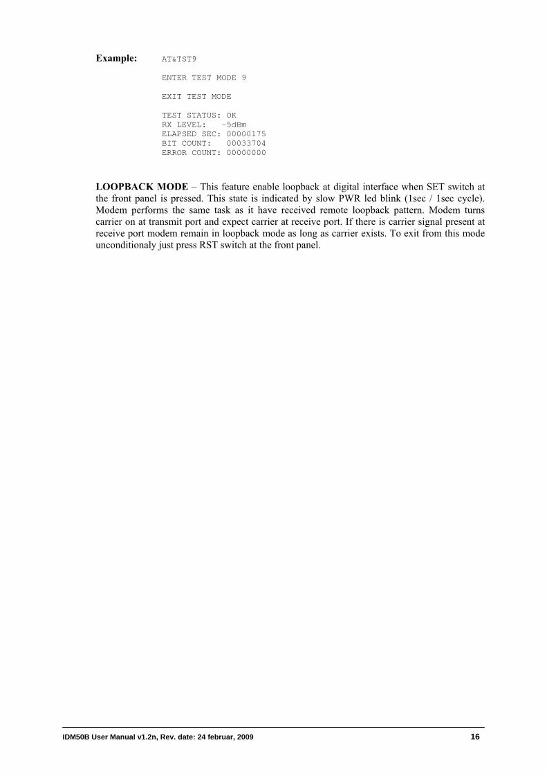
Example: AT&TST9 ENTER TEST MODE 9
EXIT TEST MODE TEST STATUS: OK RX LEVEL: -5dBm ELAPSED SEC: 00000175 BIT COUNT: 00033704 ERROR COUNT: 00000000
LOOPBACK MODE – This feature enable loopback at digital interface when SET switch at the front panel is pressed. This state is indicated by slow PWR led blink (1sec / 1sec cycle). Modem performs the same task as it have received remote loopback pattern. Modem turns carrier on at transmit port and expect carrier at receive port. If there is carrier signal present at receive port modem remain in loopback mode as long as carrier exists. To exit from this mode unconditionaly just press RST switch at the front panel.
IDM50B User Manual v1.2n, Rev. date: 24 februar, 2009 16
5. FIRMWARE UPGRADE IDM-50B has an ability to be upgraded with new firmware in the field by performing bootloading procedure. Latest version of IDM50B firmware may be found and downloaded at no charge from Decode web site http://www.decode.rs.
5.1 Bootloading Procedure
Important: Before starting with bootloading procedure make sure that modem jumper JP300 is in factory settings position 1-2 (EXT_BSL). Windows operating system on your PC must have installed JAVA Runtime Environment (JRE) v1.5 or greater. It can be downloaded at no charge from:
http://java.sun.com/j2se/corejava/
Your PC must have at least one RS232C serial port available. Bootloader procedure may be started without modem power turn-off.
Follow steps below:
1. If you already have installed C2000Prog on your PC skip steps 2 and 3.
2. Unzip bootloader program C2oooProg_v1.2d.zip on your PC. It may be found on IDM50B support CD or may be downloaded at no charge from:
http://www.code-skin.com/downloads/C2oooProg_v1.2d.zip
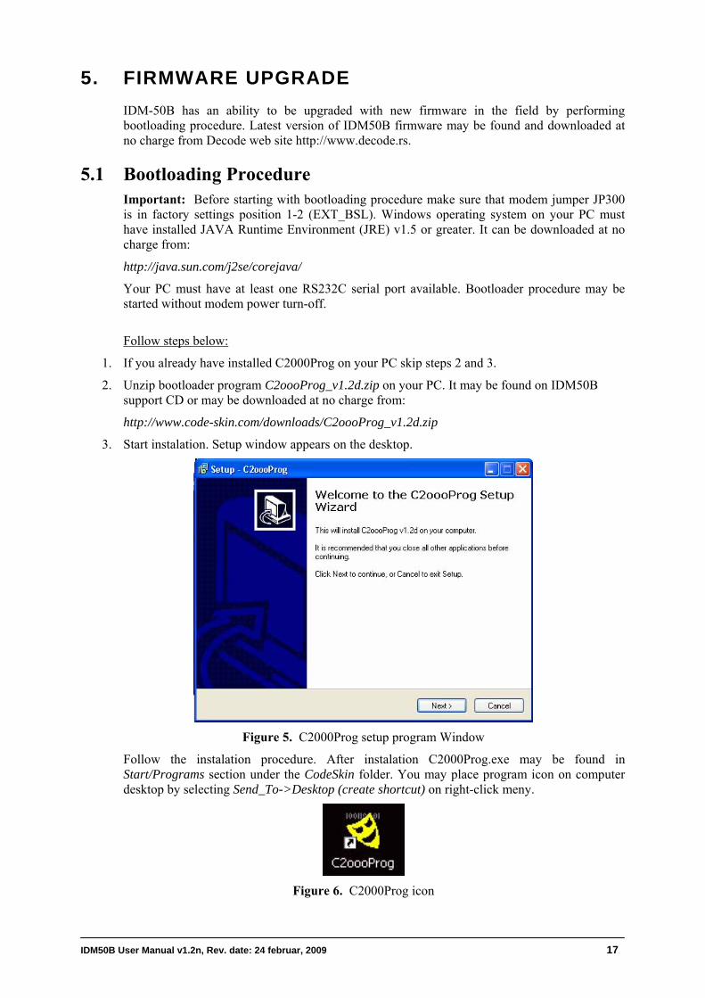
3. Start instalation. Setup window appears on the desktop.
Figure 5. C2000Prog setup program Window
Follow the instalation procedure. After instalation C2000Prog.exe may be found in Start/Programs section under the CodeSkin folder. You may place program icon on computer desktop by selecting Send_To->Desktop (create shortcut) on right-click meny.
Figure 6. C2000Prog icon
IDM50B User Manual v1.2n, Rev. date: 24 februar, 2009 17

4. Connect IDM50B bootloader adapter cable (delivered as additional accesory) at IDM50B RJ45 DIAG RS-232 port. Make sure that cable switch is at RUN position.
5. Connect avaliable PC serial COM port and bootloader adapter cable with RS-232 onal accesory).
Start C2000
communication cable (delivered as additi
6. Prog program by clicking the icon on the
7. al COM Port you are using (COM1, 2, 3 or
8.
st hold initial
10. .
button. File selection
13. window appeared, change the
14. At this point erasing and programming of modem flash must be observed. It may last about 20
15. upload is finished, close the programming dialog and exit C2000Prog program.
17. e in data mode with PWR led ON and with new firmware in flash.
rm ATI
Desktop.
Select seri4). COM1 is selected in this example.
Select Target: 2811_API2.10_30MHz.
9. Skip Code Security Keys. All labels muFFFF value. Warning: Do not change these values or modem DSP may be permanently locked, after uploading of new firmware.
Skip Flash Sector to be Erased
11. Tick Smart Sector Selection.
12. Click at Program commanddialog appeared. Select and open new firmware file. File format is Intel hex, with .hex extension. File name must be with idm50Bxx format, where xx is firmware version.
When programmingswitch position at BSL, and reset modem by short press at RST button on the front panel.
to 30 seconds.
When firmware
16. Return the switch in RUN position, and perform the modem reset by short press at RST button on the front panel.
Now modem must b
18. You may now enter command mode (section 4.2 Entering Command Mode) and perfocommand to check version of loaded firmware.
IDM50B User Manual v1.2n, Rev. date: 24 februar, 2009 18

APPENDIX A
1. IDM 50B Rack 1U (up to 3 modems)
igure A1a. Rack frame 1U/84TE - Front view
A F
Figure A1b. Rack frame 1U/84TE - Rear view
igure A1c. Rack frame 1U/84TE - Side view F
172.5
175
igure A1d. Rack 1U/28TE - Front plate view F
igure A1e. Rack 1U/28TE - Rear view F
IDM50B User Manual v1.2n, Rev. date: 24 februar, 2009 19
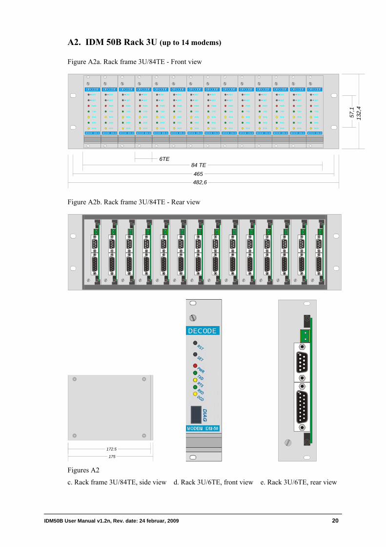
A2. IDM 50B Rack 3U (up to 14 modems) Figure A2a. Rack frame 3U/84TE - Front view
482,6
84 TE
132,
4
6TE
PWR
TXD
RTS
RXD
DCD
RST
SET
DECODE
PWR
TXD
RTS
RXD
DCD
RST
SET
DECODE
PWR
TXD
RTS
RXD
DCD
RST
SET
DECODE
PWR
TXD
RTS
RXD
DCD
RST
SET
DECODE
PWR
TXD
RTS
RXD
DCD
RST
SET
DECODE
PWR
TXD
RTS
RXD
DCD
RST
SET
DECODE
PWR
TXD
RTS
RXD
DCD
RST
SET
DECODE
PWR
TXD
RTS
RXD
DCD
RST
SET
DECODE
PWR
TXD
RTS
RXD
DCD
RST
SET
DECODE
PWR
TXD
RTS
RXD
DCD
RST
SET
DECODE
PWR
TXD
RTS
RXD
DCD
RST
SET
DECODE
PWR
TXD
RTS
RXD
DCD
RST
SET
DECODE
PWR
TXD
RTS
RXD
DCD
RST
SET
DECODE
PWR
TXD
RTS
RXD
DCD
RST
SET
DECODE
465
57,1
Figure A2b. Rack frame 3U/84TE - Rear view
175
172.5
Figures A2
c. Rack frame 3U/84TE, side view d. Rack 3U/6TE, front view e. Rack 3U/6TE, rear view
IDM50B User Manual v1.2n, Rev. date: 24 februar, 2009 20
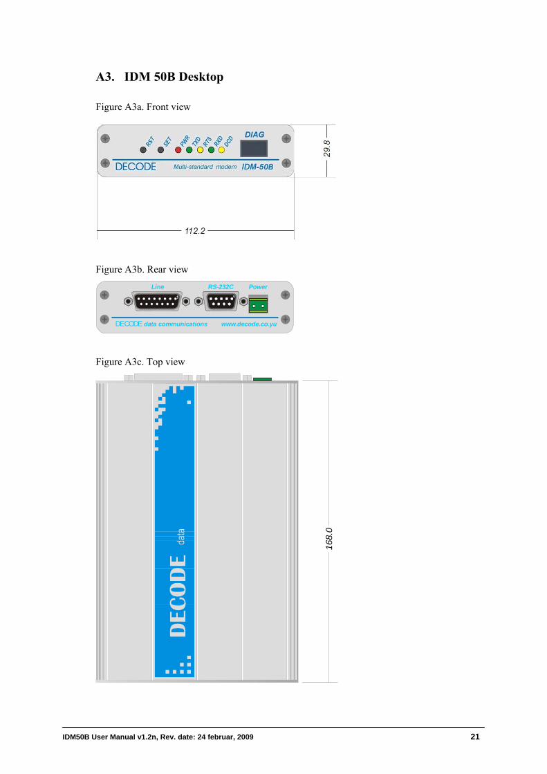
A3. IDM 50B Desktop
Figure A3a. Front view
Figure A3b. Rear view RS-232CLine
DECODE data communications www.decode.co.yu
Power
Figure A3c. Top view
168.
0
IDM50B User Manual v1.2n, Rev. date: 24 februar, 2009 21
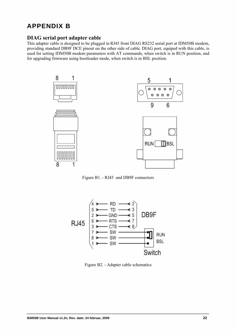
APPENDIX B
DIAG serial port adapter cable This adapter cable is designed to be plugged in RJ45 front DIAG RS232 serial port at IDM50B modem, providing standard DB9F DCE pinout on the other side of cable. DIAG port, equiped with this cable, is used for setting IDM50B modem parameters with AT commands, when switch is in RUN position, and for upgrading firmware using bootloader mode, when switch is in BSL position.
Figure B1. - RJ45 and DB9F connectors
Figure B2. - Adapter cable schematics
IDM50B User Manual v1.2n, Rev. date: 24 februar, 2009 22
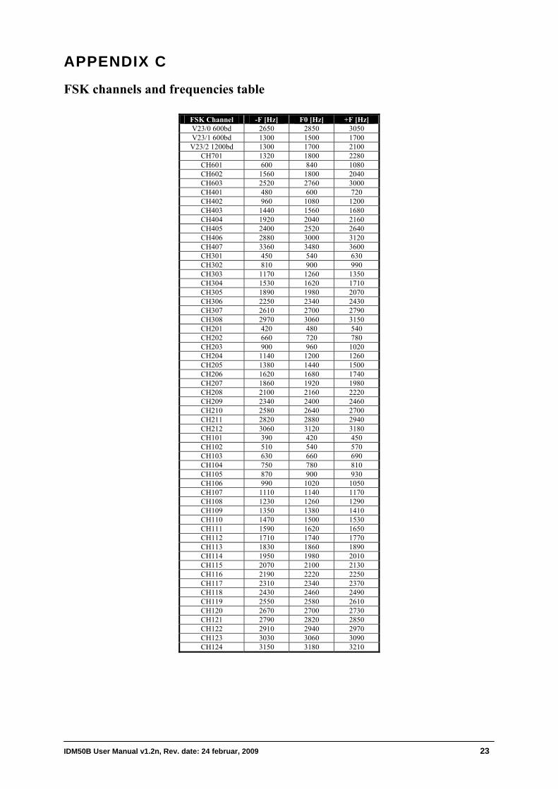
APPENDIX C
FSK channels and frequencies table
FSK Channel -F [Hz] F0 [Hz] +F [Hz] V23/0 600bd 2650 2850 3050 V23/1 600bd 1300 1500 1700 V23/2 1200bd 1300 1700 2100
CH701 1320 1800 2280 CH601 600 840 1080 CH602 1560 1800 2040 CH603 2520 2760 3000 CH401 480 600 720 CH402 960 1080 1200 CH403 1440 1560 1680 CH404 1920 2040 2160 CH405 2400 2520 2640 CH406 2880 3000 3120 CH407 3360 3480 3600 CH301 450 540 630 CH302 810 900 990 CH303 1170 1260 1350 CH304 1530 1620 1710 CH305 1890 1980 2070 CH306 2250 2340 2430 CH307 2610 2700 2790 CH308 2970 3060 3150 CH201 420 480 540 CH202 660 720 780 CH203 900 960 1020 CH204 1140 1200 1260 CH205 1380 1440 1500 CH206 1620 1680 1740 CH207 1860 1920 1980 CH208 2100 2160 2220 CH209 2340 2400 2460 CH210 2580 2640 2700 CH211 2820 2880 2940 CH212 3060 3120 3180 CH101 390 420 450 CH102 510 540 570 CH103 630 660 690 CH104 750 780 810 CH105 870 900 930 CH106 990 1020 1050 CH107 1110 1140 1170 CH108 1230 1260 1290 CH109 1350 1380 1410 CH110 1470 1500 1530 CH111 1590 1620 1650 CH112 1710 1740 1770 CH113 1830 1860 1890 CH114 1950 1980 2010 CH115 2070 2100 2130 CH116 2190 2220 2250 CH117 2310 2340 2370 CH118 2430 2460 2490 CH119 2550 2580 2610 CH120 2670 2700 2730 CH121 2790 2820 2850 CH122 2910 2940 2970 CH123 3030 3060 3090 CH124 3150 3180 3210
IDM50B User Manual v1.2n, Rev. date: 24 februar, 2009 23


![[XLS] · Web viewSGR-12 RECLOSING RELAY TT-8 RELAY PERCENTAGE DIFFERENTIAL TRANSFORMER CVE SYNCRO VERIFIER RELAY HU-4 TRANSFORMER DIFFERENTIAL RELAY HCB RELAY TD-5 TIME DELAY RELAY](https://img.pdfslide.us/doc/110x75/5aebb2387f8b9a36698eaca3/xls-viewsgr-12-reclosing-relay-tt-8-relay-percentage-differential-transformer.jpg)