Embed Size (px)
Citation preview

Copyr igh t
i
CopyrightFujitsu has made every effort to ensure theaccuracy and completeness of this document.Because ongoing development efforts aremade to continually improve the capabilities ofour products, however, the data containedherein represents Fujitsu design objectives andis provided for comparative purposes; actualresults may vary based on a variety of factors.This product data does not constitute awarranty. Specifications are subject to changewithout knowledge.
Fujitsu and the Fujitsu logo are registeredtrademarks of Fujitsu Limited; Stylistic is aregistered trademark of Fujitsu.
Microsoft and Windows are registeredtrademarks of Microsoft Corporation.
PCMCIA and CardBus are registeredtrademarks of the Personal Computer MemoryCard International Association.Intel, Pentium, and SpeedStep are registeredtrademarks of Intel Corporation.
Wi-Fi is a trademark of the Wireless EthernetCompatibility Alliance (WECA).
All other products are trademarks or registeredtrademarks of their respective companies.
Copyright 2003 - Fujitsu. All rights reserved.No part of this publication may be copied,reproduced, or translated, without the priorwritten consent of Fujitsu. No part of thispublication may be stored or transmitted in anyelectronic form without the prior consent ofFujitsu.
DECLARATION OF CONFORMITYaccording to FCC Part 15
This device complies with Part 15 of the FCC rules. Operation is subject to the following twoconditions:
(1) This device may not cause harmful interference, and, (2) This device must accept anyinterference received, including interference that may cause undesired operation.
Alb Active0 (1-2) 25/3/03, 11:59 AM1

ii
Fuj i t su Sty l i s t i c ST4120/21 Table t PC - User ’s Gu ide
Alb Active0 (1-2) 25/3/03, 11:59 AM2
Table o f Conten t
iii
Table of Contents
3CARE AND MAINTENANCECare and Maintenance ................................... 31Protecting the Display Screen ........................ 31Storing the Tablet PC ..................................... 32Avoiding Overheating ..................................... 32Cleaning the Display Screen .......................... 32Troubleshooting .............................................. 32
4SPECIFICATIONSFujitsu Stylistic ST4120/21 Table PC
Hardware Specifications ........................... 37Physical Specifications ................................... 37Processing Specifications .............................. 37Memory/Storage Specifications ..................... 37Display Specifications .................................... 37Interface Specifications .................................. 37Power Specifications ...................................... 38Environmental Specifications ......................... 38Agency Approval Specifications ..................... 38Additional Specifications ................................ 38
5AGENCY NOTICESRegulatory Information ................................... 41Notice ............................................................. 41
APPENDIXWireless LAN User’s GuideFCC Regulatory Information .......................... 47Before Using This Device ............................... 49Connecting Windows XP Systems ................. 50Troubleshooting .............................................. 54About IP Address ........................................... 58Specifications ................................................. 59
PREFACEAbout This Guide
1GETTING STARTEDWITH YOUR FUJITSUSTYLISTIC ST4120/21TABLET PCGetting Started with Your Fujitsu
Stylistic ST4120/21 Tablet PC ................... 3Fujitsu Stylistic ST4120/21 Tablet PC
Features .................................................... 4Status Display ................................................ 9Application Buttons ........................................ 11Navigation Buttons ......................................... 13Tertiary Functions Of Application
and Navigation Buttons ............................. 14Connectors And Peripheral Interfaces ........... 15
2USING YOUR FUJITSUSTYLISTIC ST4120/21TABLET PCUsing the Fujitsu Stylistic ST4120/21
Tablet PC .................................................. 19System States ................................................ 19Powering Up the Table PC ............................. 20Shutting Down the System ............................. 20Suspending System Operating ...................... 20Resuming System Operation ......................... 22Adjiusting the Display Brightness ................... 22Using the Pen ................................................. 22Calibrating the Pen ......................................... 23Installing a Pen Tether .................................... 23Replacing the Pen Tip .................................... 24Charging the Battery ...................................... 24Removing and Installing
the Battery ................................................ 24Tips for Conserving Battery Power ................ 25Modem Connection ........................................ 25PC Card Slot .................................................. 26Removing and Installing
Memory Modules ...................................... 26
Alb Active0 (3-4TOC) 25/3/03, 11:59 AM3

iv
Fuj i t su Sty l i s t i c ST4120/21 Table t PC - User ’s Gu ide
Alb Active0 (3-4TOC) 25/3/03, 11:59 AM4

v
Preface
Alb Active0 (5-10) 25/3/03, 12:00 PM5

vi
Fuj i t su Sty l i s t i c ST4120/21 Table t PC - User ’s Gu ide
Alb Active0 (5-10) 25/3/03, 12:00 PM6
vii
Preface
vii
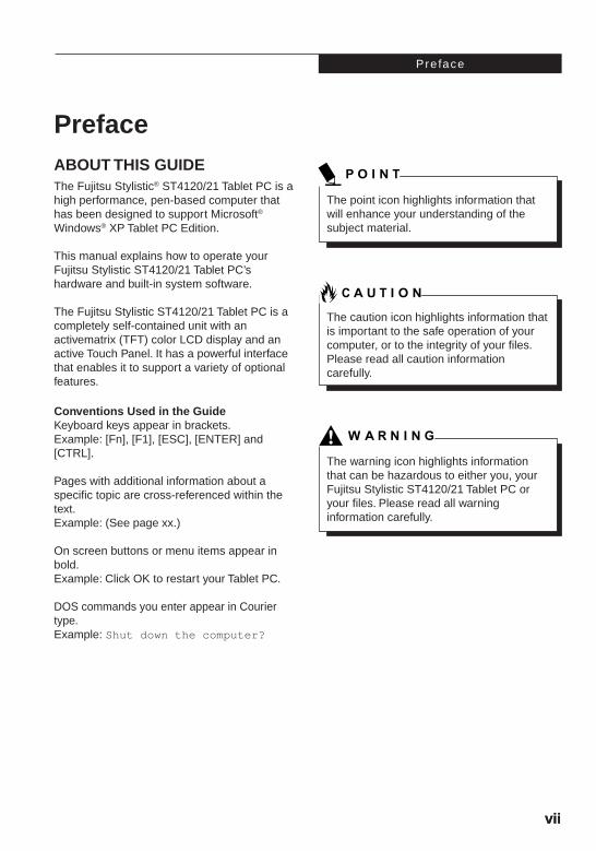
PrefaceABOUT THIS GUIDEThe Fujitsu Stylistic® ST4120/21 Tablet PC is ahigh performance, pen-based computer thathas been designed to support Microsoft®
Windows® XP Tablet PC Edition.
This manual explains how to operate yourFujitsu Stylistic ST4120/21 Tablet PC’shardware and built-in system software.
The Fujitsu Stylistic ST4120/21 Tablet PC is acompletely self-contained unit with anactivematrix (TFT) color LCD display and anactive Touch Panel. It has a powerful interfacethat enables it to support a variety of optionalfeatures.
Conventions Used in the GuideKeyboard keys appear in brackets.Example: [Fn], [F1], [ESC], [ENTER] and[CTRL].
Pages with additional information about aspecific topic are cross-referenced within thetext.Example: (See page xx.)
On screen buttons or menu items appear inbold.Example: Click OK to restart your Tablet PC.
DOS commands you enter appear in Couriertype.Example: Shut down the computer?
The point icon highlights information thatwill enhance your understanding of thesubject material.
The caution icon highlights information thatis important to the safe operation of yourcomputer, or to the integrity of your files.Please read all caution informationcarefully.
The warning icon highlights informationthat can be hazardous to either you, yourFujitsu Stylistic ST4120/21 Tablet PC oryour files. Please read all warninginformation carefully.
Alb Active0 (5-10) 25/3/03, 12:00 PM7
viii
Fuj i t su Sty l i s t i c ST4120/21 Table t PC - User ’s Gu ide
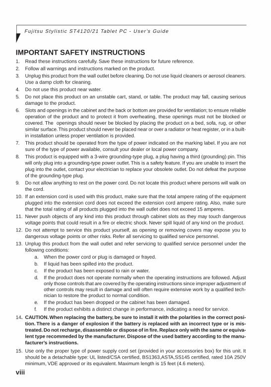
IMPORTANT SAFETY INSTRUCTIONS1. Read these instructions carefully. Save these instructions for future reference.
2. Follow all warnings and instructions marked on the product.
3. Unplug this product from the wall outlet before cleaning. Do not use liquid cleaners or aerosol cleaners.Use a damp cloth for cleaning.
4. Do not use this product near water.
5. Do not place this product on an unstable cart, stand, or table. The product may fall, causing seriousdamage to the product.
6. Slots and openings in the cabinet and the back or bottom are provided for ventilation; to ensure reliableoperation of the product and to protect it from overheating, these openings must not be blocked orcovered. The openings should never be blocked by placing the product on a bed, sofa, rug, or othersimilar surface. This product should never be placed near or over a radiator or heat register, or in a built-in installation unless proper ventilation is provided.
7. This product should be operated from the type of power indicated on the marking label. If you are notsure of the type of power available, consult your dealer or local power company.
8. This product is equipped with a 3-wire grounding-type plug, a plug having a third (grounding) pin. Thiswill only plug into a grounding-type power outlet. This is a safety feature. If you are unable to insert theplug into the outlet, contact your electrician to replace your obsolete outlet. Do not defeat the purposeof the grounding-type plug.
9. Do not allow anything to rest on the power cord. Do not locate this product where persons will walk onthe cord.
10. If an extension cord is used with this product, make sure that the total ampere rating of the equipmentplugged into the extension cord does not exceed the extension cord ampere rating. Also, make surethat the total rating of all products plugged into the wall outlet does not exceed 15 amperes.
11. Never push objects of any kind into this product through cabinet slots as they may touch dangerousvoltage points that could result in a fire or electric shock. Never spill liquid of any kind on the product.
12. Do not attempt to service this product yourself, as opening or removing covers may expose you todangerous voltage points or other risks. Refer all servicing to qualified service personnel.
13. Unplug this product from the wall outlet and refer servicing to qualified service personnel under thefollowing conditions:
a. When the power cord or plug is damaged or frayed.b. If liquid has been spilled into the product.c. If the product has been exposed to rain or water.d. If the product does not operate normally when the operating instructions are followed. Adjust
only those controls that are covered by the operating instructions since improper adjustment ofother controls may result in damage and will often require extensive work by a qualified tech-nician to restore the product to normal condition.
e. If the product has been dropped or the cabinet has been damaged.f. If the product exhibits a distinct change in performance, indicating a need for service.
14. CAUTION. When replacing the battery, be sure to install it with the polarities in the correct posi-tion. There is a danger of explosion if the battery is replaced with an incorrect type or is mis-treated. Do not recharge, disassemble or dispose of in fire. Replace only with the same or equiva-lent type recommeded by the manufacturer. Dispose of the used battery according to the manu-facturer’s instructions.
15. Use only the proper type of power supply cord set (provided in your accessories box) for this unit. Itshould be a detachable type: UL listed/CSA certified, BS1363,ASTA,SS145 certified, rated 10A 250Vminimum, VDE approved or its equivalent. Maximum length is 15 feet (4.6 meters).
Alb Active0 (5-10) 25/3/03, 12:00 PM8

ix
Preface
ix
HIGH SAFETY REQUIRED USEThis Product is designed, developed and manufactured as contemplated for general use, including withoutlimitation, general office use, personal use, household use and ordinary industrial use, but is notdesigned,developed and manufactured as contemplated for use accompanying fatal risks or dangers that,unless extremely high safety is secured, could lead directly to death, personal injury,severe physical dam-age or other loss (hereinafter ‘High Safety Required Use’), including without limitation, nuclear powerreactioncore control in nuclear atomic facility, airplane automatic aircraft flight control, air traffic control,operation control in mass transport control system,medical instrument for life support system, missile launch-ing control in weapon system. You shall not use this Product without securing the sufficient safety requiredfor the High Safety Required Use.
Alb Active0 (5-10) 25/3/03, 12:00 PM9
x
Fuj i t su Sty l i s t i c ST4120/21 Table t PC - User ’s Gu ide
DATA STORAGE MEDIA AND CUSTOMER RESPONSIBILITIESThe only effective protection for the data stored in a computer,such as on a hard disk,is for you, Purchaserto regularly back up the data.Fujitsu and its affiliates,suppliers,service providers and resellers shall not beresponsible for any software programs,data or other information stored or used on any media or part of anyProduct returned to Fujitsu or its service providers for Warranty Service or other repair,including but notlimited to the costs of recovering such programs,data or other information.It is solely your responsibility asthe Purchaser to back up any software programs, data,or information stored on any storage media or anypart of a Product returned for Warranty Service or repair to the designated service centers.
Alb Active0 (5-10) 25/3/03, 12:00 PM10
1
Getting Startedwith Your FujitsuStylistic ST4120/21Tablet PC
1
Alb Active1 (1-16) 25/3/03, 12:00 PM1

2
Fuj i t su Sty l i s t i c ST4120/21 Table t PC User ’s Gu ide - Sec t ion One
Alb Active1 (1-16) 25/3/03, 12:00 PM2
Get t ing Star ted
3
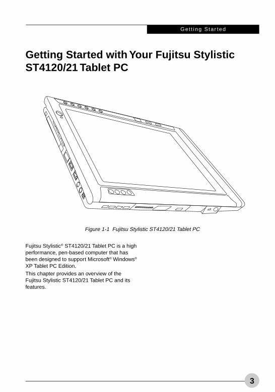
Getting Started with Your Fujitsu StylisticST4120/21 Tablet PC
Fujitsu Stylistic® ST4120/21 Tablet PC is a highperformance, pen-based computer that hasbeen designed to support Microsoft® Windows®
XP Tablet PC Edition.This chapter provides an overview of theFujitsu Stylistic ST4120/21 Tablet PC and itsfeatures.
Figure 1-1 Fujitsu Stylistic ST4120/21 Tablet PC
Alb Active1 (1-16) 25/3/03, 12:00 PM3
4
Fuj i t su Sty l i s t i c ST4120/21 Table t PC User ’s Gu ide - Sec t ion One
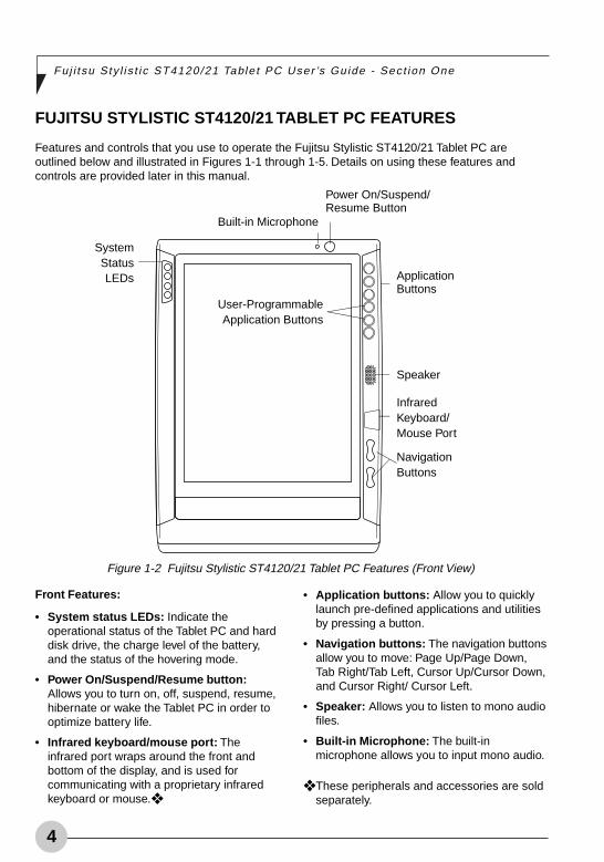
FUJITSU STYLISTIC ST4120/21 TABLET PC FEATURES
Features and controls that you use to operate the Fujitsu Stylistic ST4120/21 Tablet PC areoutlined below and illustrated in Figures 1-1 through 1-5. Details on using these features andcontrols are provided later in this manual.
Front Features:
• System status LEDs: Indicate theoperational status of the Tablet PC and harddisk drive, the charge level of the battery,and the status of the hovering mode.
• Power On/Suspend/Resume button:Allows you to turn on, off, suspend, resume,hibernate or wake the Tablet PC in order tooptimize battery life.
• Infrared keyboard/mouse port: Theinfrared port wraps around the front andbottom of the display, and is used forcommunicating with a proprietary infraredkeyboard or mouse.❖
• Application buttons: Allow you to quicklylaunch pre-defined applications and utilitiesby pressing a button.
• Navigation buttons: The navigation buttonsallow you to move: Page Up/Page Down,Tab Right/Tab Left, Cursor Up/Cursor Down,and Cursor Right/ Cursor Left.
• Speaker: Allows you to listen to mono audiofiles.
• Built-in Microphone: The built-inmicrophone allows you to input mono audio.
❖ These peripherals and accessories are soldseparately.
SystemStatusLEDs Application
Buttons
Speaker
InfraredKeyboard/Mouse Port
NavigationButtons
Built-in Microphone
Power On/Suspend/Resume Button
Figure 1-2 Fujitsu Stylistic ST4120/21 Tablet PC Features (Front View)
User-ProgrammableApplication Buttons
Alb Active1 (1-16) 25/3/03, 12:00 PM4
Get t ing Star ted
5
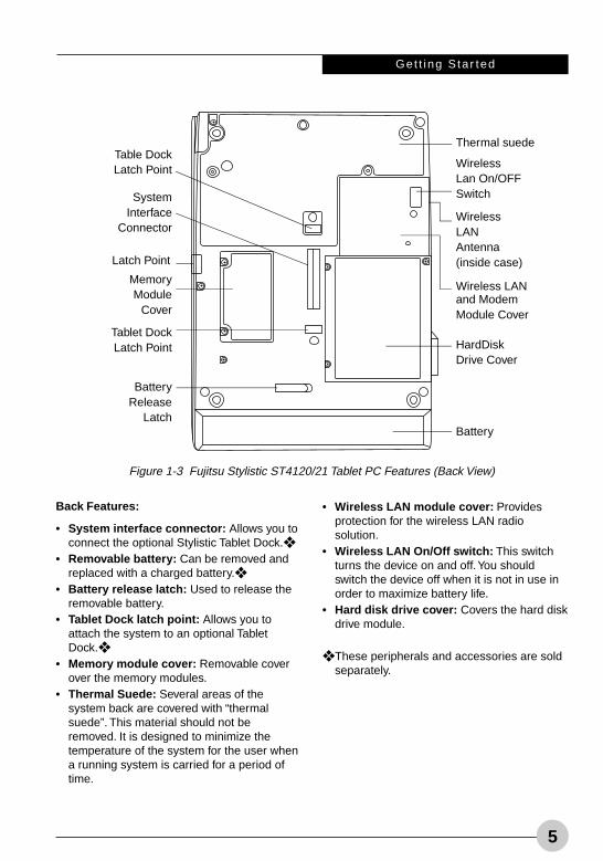
Back Features:
• System interface connector: Allows you toconnect the optional Stylistic Tablet Dock.❖
• Removable battery: Can be removed andreplaced with a charged battery.❖
• Battery release latch: Used to release theremovable battery.
• Tablet Dock latch point: Allows you toattach the system to an optional TabletDock.❖
• Memory module cover: Removable coverover the memory modules.
• Thermal Suede: Several areas of thesystem back are covered with “thermalsuede”. This material should not beremoved. It is designed to minimize thetemperature of the system for the user whena running system is carried for a period oftime.
• Wireless LAN module cover: Providesprotection for the wireless LAN radiosolution.
• Wireless LAN On/Off switch: This switchturns the device on and off. You shouldswitch the device off when it is not in use inorder to maximize battery life.
• Hard disk drive cover: Covers the hard diskdrive module.
❖ These peripherals and accessories are soldseparately.
Figure 1-3 Fujitsu Stylistic ST4120/21 Tablet PC Features (Back View)
Battery
HardDiskDrive Cover
WirelessLANAntenna(inside case)
Wireless LANand ModemModule Cover
WirelessLan On/OFFSwitch
Thermal suedeTable DockLatch Point
SystemInterface
Connector
Latch Point
MemoryModule
Cover
Tablet DockLatch Point
BatteryRelease
Latch
Alb Active1 (1-16) 25/3/03, 12:00 PM5
6
Fuj i t su Sty l i s t i c ST4120/21 Table t PC User ’s Gu ide - Sec t ion One
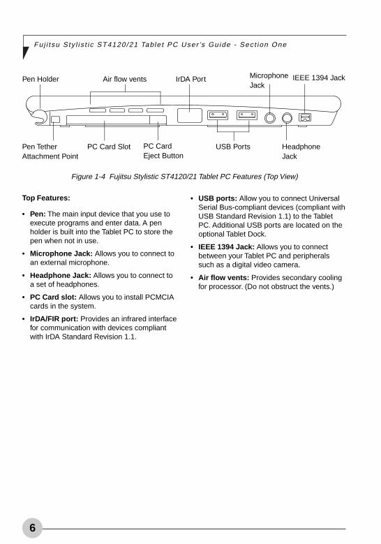
Top Features:
• Pen: The main input device that you use toexecute programs and enter data. A penholder is built into the Tablet PC to store thepen when not in use.
• Microphone Jack: Allows you to connect toan external microphone.
• Headphone Jack: Allows you to connect toa set of headphones.
• PC Card slot: Allows you to install PCMCIAcards in the system.
• IrDA/FIR port: Provides an infrared interfacefor communication with devices compliantwith IrDA Standard Revision 1.1.
• USB ports: Allow you to connect UniversalSerial Bus-compliant devices (compliant withUSB Standard Revision 1.1) to the TabletPC. Additional USB ports are located on theoptional Tablet Dock.
• IEEE 1394 Jack: Allows you to connectbetween your Tablet PC and peripheralssuch as a digital video camera.
• Air flow vents: Provides secondary coolingfor processor. (Do not obstruct the vents.)
Pen Holder Air flow vents IrDA Port MicrophoneJack
IEEE 1394 Jack
Pen TetherAttachment Point
PC Card Slot PC CardEject Button
USB Ports HeadphoneJack
Figure 1-4 Fujitsu Stylistic ST4120/21 Tablet PC Features (Top View)
Alb Active1 (1-16) 25/3/03, 12:00 PM6
Get t ing Star ted
7
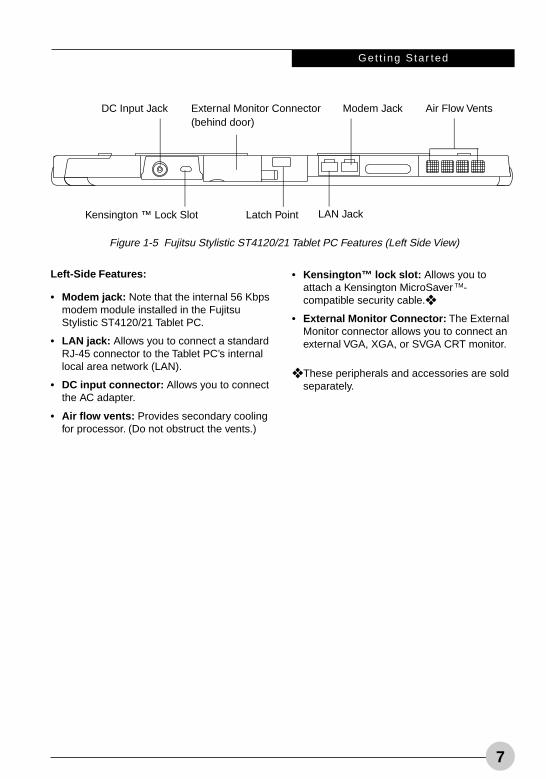
Left-Side Features:
• Modem jack: Note that the internal 56 Kbpsmodem module installed in the FujitsuStylistic ST4120/21 Tablet PC.
• LAN jack: Allows you to connect a standardRJ-45 connector to the Tablet PC’s internallocal area network (LAN).
• DC input connector: Allows you to connectthe AC adapter.
• Air flow vents: Provides secondary coolingfor processor. (Do not obstruct the vents.)
• Kensington™ lock slot: Allows you toattach a Kensington MicroSaver TM-compatible security cable.❖
• External Monitor Connector: The ExternalMonitor connector allows you to connect anexternal VGA, XGA, or SVGA CRT monitor.
❖ These peripherals and accessories are soldseparately.
Kensington ™ Lock Slot
Figure 1-5 Fujitsu Stylistic ST4120/21 Tablet PC Features (Left Side View)
DC Input Jack External Monitor Connector(behind door)
Modem Jack Air Flow Vents
Latch Point LAN Jack
Alb Active1 (1-16) 25/3/03, 12:00 PM7
8
Fuj i t su Sty l i s t i c ST4120/21 Table t PC User ’s Gu ide - Sec t ion One
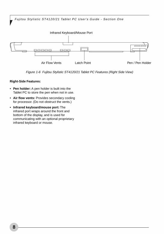
Right-Side Features:
• Pen holder: A pen holder is built into theTablet PC to store the pen when not in use.
• Air flow vents: Provides secondary coolingfor processor. (Do not obstruct the vents.)
• Infrared keyboard/mouse port: Theinfrared port wraps around the front andbottom of the display, and is used forcommunicating with an optional proprietaryinfrared keyboard or mouse.
Infrared Keyboard/Mouse Port
Figure 1-6 Fujitsu Stylistic ST4120/21 Tablet PC Features (Right Side View)
Air Flow Vents Latch Point Pen / Pen Holder
Alb Active1 (1-16) 25/3/03, 12:00 PM8
Get t ing Star ted
9
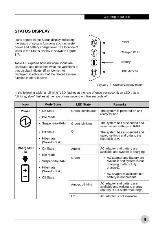
STATUS DISPLAY
Icons appear in the Status display indicatingthe status of system functions such as systempower and battery charge level. The location oficons in the Status display is shown in Figure1-7.
Table 1-2 explains how individual icons aredisplayed, and describes what the variations ofthat display indicate. (If an icon is notdisplayed, it indicates that the related systemfunction is off or inactive.
In the following table, a “blinking” LED flashes at the rate of once per second; an LED that is“blinking, slow” flashes at the rate of one second on, five seconds off.
Icon Mode/State LED State Remarks
• On State
• Idle Mode
• Suspend-to-RAM
• Off State
• Hibernate(Save-to-Disk)
• On State
• Idle Mode
• Suspend-to-RAM
• Hibernate(Save-to-Disk)
• Off State
Green, continuous
Green, blinking
Off
Amber
Green
Amber, blinking
Off
The system is powered on andready for use.
The system has suspended andsaved active settings to RAM.
The system has suspended andsaved settings and data to thehard disk drive.
AC adapter and battery areavailable and system is charging.
• AC adapter and battery areavailable and system is notcharging (battery fullycharged).
• AC adapter is available butbattery is not present.
AC adapter and battery areavailable and waiting to charge(battery is out of thermal range).
AC adapter is not available.
Figure 1-7 Stylistic Display Icons
Power
Charge/DC In
Battery
HDD Access
Power
Charge/DCIn
Alb Active1 (1-16) 25/3/03, 12:00 PM9
10
Fuj i t su Sty l i s t i c ST4120/21 Table t PC User ’s Gu ide - Sec t ion One
Icon Mode/State LED State Remarks
• On State
• Idle Mode
• Suspend-to-RAM,without AC adapter
• Suspend-to-RAM,with AC adapter
• Hibernate(Save-to-Disk),without AC adapter
• Off State
• Hibernate(Save-to-Disk)without AC adapter
• Off State
• On State(or flasing)
• Idle Mode
• Suspend-to-RAM
• Hibernate(Save-to-Disk)
• Off State
Green, continuous
Amber, continuous
Red, continuous
Red, blinking
Green, blinkingslow
Amber, blinkingslow
Red, blinking slow
Off
Green
Off
Battery charge is between 50% –100%.
Battery charge is between 13% –49%.
Battery charge is between 0% –12%.
There is a battery error.
Battery charge is between 50% –100%.
Battery charge is between 13% –49%.
Battery charge is between 0% –12%.
Battery is not installed, or systemis off or in Hibernate mode.
If battery is inserted during poweroff, LED blinks amber for 4seconds to detect battery. Batterystatus is displayed for 5 secondsafter that.
Displayed when hard disk drive isaccessed.
Hard disk drive is not beingaccessed.
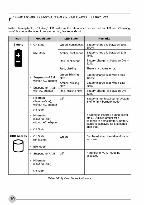
Table 1-2 System Status Indicators
Battery
HDD Access
In the following table, a “blinking” LED flashes at the rate of once per second; an LED that is “blinking,slow” flashes at the rate of one second on, five seconds off.
Alb Active1 (1-16) 25/3/03, 12:00 PM10
Get t ing Star ted
11
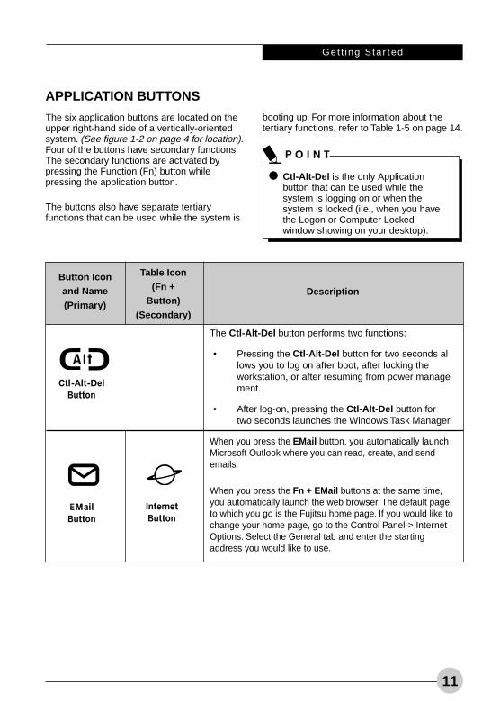
APPLICATION BUTTONS
The six application buttons are located on theupper right-hand side of a vertically-orientedsystem. (See figure 1-2 on page 4 for location).Four of the buttons have secondary functions.The secondary functions are activated bypressing the Function (Fn) button whilepressing the application button.
The buttons also have separate tertiaryfunctions that can be used while the system is
booting up. For more information about thetertiary functions, refer to Table 1-5 on page 14.
Button Iconand Name(Primary)
Table Icon(Fn +
Button)(Secondary)
Description
The Ctl-Alt-Del button performs two functions:
• Pressing the Ctl-Alt-Del button for two seconds allows you to log on after boot, after locking theworkstation, or after resuming from power management.
• After log-on, pressing the Ctl-Alt-Del button fortwo seconds launches the Windows Task Manager.
When you press the EMail button, you automatically launchMicrosoft Outlook where you can read, create, and sendemails.
When you press the Fn + EMail buttons at the same time,you automatically launch the web browser. The default pageto which you go is the Fujitsu home page. If you would like tochange your home page, go to the Control Panel-> InternetOptions. Select the General tab and enter the startingaddress you would like to use.
Ctl-Alt-Del is the only Applicationbutton that can be used while thesystem is logging on or when thesystem is locked (i.e., when you havethe Logon or Computer Lockedwindow showing on your desktop).
Alb Active1 (1-16) 25/3/03, 12:01 PM11
12
Fuj i t su Sty l i s t i c ST4120/21 Table t PC User ’s Gu ide - Sec t ion One
Button Iconand Name(Primary)
Table Icon(Fn +
Button)(Secondary)
Description
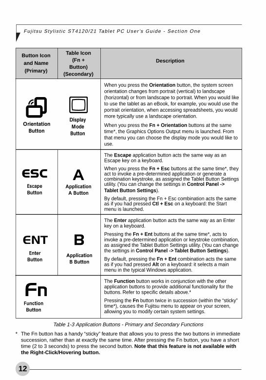
When you press the Orientation button, the system screenorientation changes from portrait (vertical) to landscape(horizontal) or from landscape to portrait. When you would liketo use the tablet as an eBook, for example, you would use theportrait orientation, when accessing spreadsheets, you wouldmore typically use a landscape orientation.
When you press the Fn + Orientation buttons at the sametime*, the Graphics Options Output menu is launched. Fromthat menu you can choose the display mode you would like touse.
The Escape application button acts the same way as anEscape key on a keyboard.
When you press the Fn + Esc buttons at the same time*, theyact to invoke a pre-determined application or generate acombination keystroke, as assigned the Tablet Button Settingsutility. (You can change the settings in Control Panel ->Tablet Button Settings).
By default, pressing the Fn + Esc combination acts the sameas if you had pressed Ctl + Esc on a keyboard: the Startmenu is launched.
The Enter application button acts the same way as an Enterkey on a keyboard.
Pressing the Fn + Ent buttons at the same time*, acts toinvoke a pre-determined application or keystroke combination,as assigned the Tablet Button Settings utility. (You can changethe settings in Control Panel -> Tablet Button Settings).
By default, pressing the Fn + Ent combination acts the sameas if you had pressed Alt on a keyboard: it selects a mainmenu in the typical Windows application.
The Function button works in conjunction with the otherapplication buttons to provide additional functionality for thebuttons. Refer to specific details above.*
Pressing the Fn button twice in succession (within the “sticky”time*), causes the Fujitsu menu to appear on your screen,allowing you to modify certain system settings.
Table 1-3 Application Buttons - Primary and Secondary Functions
* The Fn button has a handy “sticky” feature that allows you to press the two buttons in immediatesuccession, rather than at exactly the same time. After pressing the Fn button, you have a shorttime (2 to 3 seconds) to press the second button. Note that this feature is not available withthe Right-Click/Hovering button.
Alb Active1 (1-16) 25/3/03, 12:01 PM12
Get t ing Star ted
13
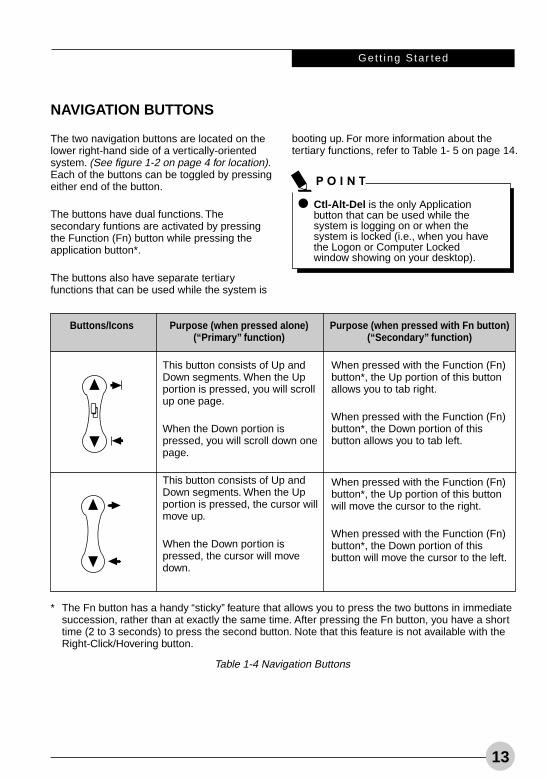
NAVIGATION BUTTONS
The two navigation buttons are located on thelower right-hand side of a vertically-orientedsystem. (See figure 1-2 on page 4 for location).Each of the buttons can be toggled by pressingeither end of the button.
The buttons have dual functions. Thesecondary funtions are activated by pressingthe Function (Fn) button while pressing theapplication button*.
The buttons also have separate tertiaryfunctions that can be used while the system is
booting up. For more information about thetertiary functions, refer to Table 1- 5 on page 14.
Buttons/Icons Purpose (when pressed alone)(“Primary” function)
This button consists of Up andDown segments. When the Upportion is pressed, you will scrollup one page.
When the Down portion ispressed, you will scroll down onepage.
This button consists of Up andDown segments. When the Upportion is pressed, the cursor willmove up.
When the Down portion ispressed, the cursor will movedown.
Purpose (when pressed with Fn button)(“Secondary” function)
When pressed with the Function (Fn)button*, the Up portion of this buttonallows you to tab right.
When pressed with the Function (Fn)button*, the Down portion of thisbutton allows you to tab left.
When pressed with the Function (Fn)button*, the Up portion of this buttonwill move the cursor to the right.
When pressed with the Function (Fn)button*, the Down portion of thisbutton will move the cursor to the left.
* The Fn button has a handy “sticky” feature that allows you to press the two buttons in immediatesuccession, rather than at exactly the same time. After pressing the Fn button, you have a shorttime (2 to 3 seconds) to press the second button. Note that this feature is not available with theRight-Click/Hovering button.
Table 1-4 Navigation Buttons
Ctl-Alt-Del is the only Applicationbutton that can be used while thesystem is logging on or when thesystem is locked (i.e., when you havethe Logon or Computer Lockedwindow showing on your desktop).
Alb Active1 (1-16) 25/3/03, 12:01 PM13
14
Fuj i t su Sty l i s t i c ST4120/21 Table t PC User ’s Gu ide - Sec t ion One
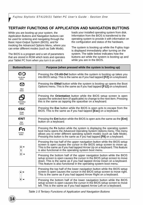
While you are booting up your system, theApplication Buttons and Navigation buttons canbe used for entering and navigating through theBasic Input-Output System (BIOS), and forinvoking the Advanced Options Menu, where youcan enter different modes (such as Safe Mode).
The BIOS is a program and a set of parametersthat are stored in ROM which tests and operatesyour Tablet PC from when you turn it on until it
TERTIARY FUNCTIONS OF APPLICATION AND NAVIGATION BUTTONSloads your installed operating system from disk.Information from the BIOS is transferred to theoperating system to provide it with information onthe configuration and status of the hardware.
The system is booting up while the Fujitsu logois displayed immediately after turning on thesystem. The table below indicates how thebuttons act while the system is booting up andwhile you are in the BIOS.
Buttons/Icons
Pressing the Ctl-Alt-Del button while the system is booting up takes youinto BIOS setup. This is the same as if you had tapped [F2] on a keyboard.
Pressing the EMail button while the system is booting up opens the BootOptions menu. This is the same as if you had tapped [F12] on a keyboard.
Pressing the Orientation button while the BIOS setup screen is opencauses the selected item (if applicable) to change to the next item. Pressingthis is the same as tapping the spacebar on a keyboard.
Pressing the Esc button while the BIOS is open acts to escape from theBIOS. This is the same as if you had tapped [Esc] on a keyboard.
Pressing the Ent button while the BIOS is open acts the same as the [Ent]button on a keyboard.
Pressing the Fn button while the system is displaying the operating systemboot menu opens the Advanced Operating System Options menu. This menuallows you to enter different operating system modes (such as Safe Mode).Pressing this button is the same as if you had tapped [F8] on a keyboard.
Pressing the top half of the upper navigation button while the BIOS setupscreen is open causes the cursor in the BIOS setup screen to move up.This is the same as if you had tapped Arrow Up on a keyboard. This featureis also functional in the operating system boot menu.
Pressing the bottom half of the upper navigation button while the BIOSsetup screen is open causes the cursor in the BIOS setup screen to movedown. This is the same as if you had tapped Arrow Down on a keyboard.This feature is also functional in the operating system boot menu.
Pressing the top half of the lower navigation button while the BIOS setupscreen is open causes the cursor in the BIOS setup screen to move right.This is the same as if you had tapped Arrow Right on a keyboard.
Pressing the bottom half of the lower navigation button while the BIOSsetup screen is open causes the cursor in the BIOS setup screen to moveleft. This is the same as if you had tapped Arrow Left on a keyboard.
Table 1-5 Tertiary Functions of Application and Navigation Buttons
Purpose (when pressed while the system is booting up)
Alb Active1 (1-16) 25/3/03, 12:01 PM14
Get t ing Star ted
15
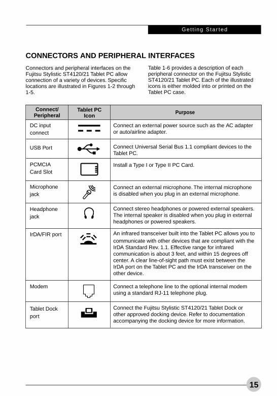
Connectors and peripheral interfaces on theFujitsu Stylistic ST4120/21 Tablet PC allowconnection of a variety of devices. Specificlocations are illustrated in Figures 1-2 through1-5.
CONNECTORS AND PERIPHERAL INTERFACES
Table 1-6 provides a description of eachperipheral connector on the Fujitsu StylisticST4120/21 Tablet PC. Each of the illustratedicons is either molded into or printed on theTablet PC case.
DC inputconnect
USB Port
PCMCIACard Slot
Microphonejack
Headphonejack
IrDA/FIR port
Modem
Tablet Dockport
Connect an external power source such as the AC adapteror auto/airline adapter.
Connect Universal Serial Bus 1.1 compliant devices to theTablet PC.
Install a Type I or Type II PC Card.
Connect an external microphone. The internal microphoneis disabled when you plug in an external microphone.
Connect stereo headphones or powered external speakers.The internal speaker is disabled when you plug in externalheadphones or powered speakers.
An infrared transceiver built into the Tablet PC allows you tocommunicate with other devices that are compliant with theIrDA Standard Rev. 1.1. Effective range for infraredcommunication is about 3 feet, and within 15 degrees offcenter. A clear line-of-sight path must exist between theIrDA port on the Tablet PC and the IrDA transceiver on theother device.
Connect a telephone line to the optional internal modemusing a standard RJ-11 telephone plug.
Connect the Fujitsu Stylistic ST4120/21 Tablet Dock orother approved docking device. Refer to documentationaccompanying the docking device for more information.
Tablet PCIcon
PurposeConnect/Peripheral
Alb Active1 (1-16) 25/3/03, 12:01 PM15
16
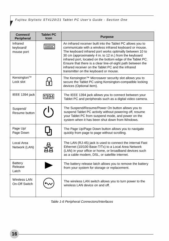
Fuj i t su Sty l i s t i c ST4120/21 Table t PC User ’s Gu ide - Sec t ion One
Infraredkeyboard/mouse port
KensingtonTM
Lock slot
IEEE 1394 jack
Suspend/Resume button
Page Up/Page Down
Local AreaNetwork (LAN)
BatteryReleaseLatch
Wireless LANOn-Off Switch
An infrared receiver built into the Tablet PC allows you tocommunicate with a wireless infrared keyboard or mouse.The keyboard infrared port works optimally between 10 to30 cm (approximately 4 in. to 12 in.) from the keyboardinfrared port, located on the bottom edge of the Tablet PC.Ensure that there is a clear line-of-sight path between theinfrared receiver on the Tablet PC and the infraredtransmitter on the keyboard or mouse.
The Kensington™ Microsaver security slot allows you tosecure the Tablet PC using Kensington-compatible lockingdevices (Optional item).
The IEEE 1394 jack allows you to connect between yourTablet PC and peripherals such as a digital video camera.
The Suspend/Resume/Power On button allows you tosuspend Tablet PC activity without powering off, resumeyour Tablet PC from suspend mode, and power on thesystem when it has been shut down from Windows.
The Page Up/Page Down button allows you to navigatequickly from page to page without scrolling.
The LAN (RJ-45) jack is used to connect the internal FastEthernet (10/100 Base-T/Tx) to a Local Area Network(LAN) in your office or home, or broadband devices suchas a cable modem, DSL, or satellite internet.
The battery release latch allows you to remove the batteryfrom your system for storage or replacement.
The wireless LAN switch allows you to turn power to thewireless LAN device on and off.
Tablet PCIcon
Table 1-6 Peripheral Connectors/Interfaces
Connect/Peripheral Purpose
Alb Active1 (1-16) 25/3/03, 12:01 PM16
17
Using YourFujitsu StylisticST4120/21Tablet PC
22222
Alb Active2 (17-28) 25/3/03, 12:01 PM17

18
Fuj i t su Sty l i s t i c ST4120/21 Table t PC User ’s Gu ide - Sec t ion One
Alb Active2 (17-28) 25/3/03, 12:01 PM18
Using Your S ty l i s t i c ST4120/21
19
Using the Fujitsu Stylistic ST4120/21 Tablet PCThis chapter covers the fundamental concepts,basic system operation and use, and systemfunctions of the Fujitsu Stylistic ST4120/21Tablet PC. You should familiarize yourself withthis information before you attempt to operatethe system.
SYSTEM STATESBefore you begin using the Fujitsu StylisticST4120/21 Tablet PC, review the differentsystem states (or modes) that the system canuse. Being familiar with these states will helpyou determine whether it is appropriate to turnon, resume, suspend, hibernate or shut downthe system when you begin or end a session.System behavior for each system state isdescribed briefly in the following, with eachsystem state listed in decreasing order ofpower usage:
• On state: The system is running and thedisplay screen is on.
• Idle state: Some system functions areregulated or turned off to conserve power.The display screen may be turned off. Thesystem returns to the On state when penactivity or other input is detected.
• Suspend-to-RAM mode (S3): Systemoperation is suspended. Most systemfunctions are turned off to conserve power.Power to memory is on, maintaining data inprograms that were running before systemoperation was suspended. The system does
not respond to the pen or other input whenin Suspend-to-RAM mode. Refer to the“Resuming System Operation” section laterin this chapter for information on returningthe system to the On state.
• Hibernate mode (Save-to-Disk) (S4):System operation is suspended. All systemfunctions are turned off to conserve power.Active data in programs that were runningbefore suspending system operation isstored on the hard disk drive. The systemdoes not respond to the pen or other input.Refer to the “Resuming System Operation”section later in this chapter for informationon returning the system to the On state.
• Off state: All system functions are turned offto conserve power. The system does notrespond to the pen or other input. Thesystem boots at the next system power-on.
Your system may be configured to enter someof these states automatically after a period ofinactivity to conserve battery power.
When you use the Fujitsu Stylistic ST4120/21Tablet PC, you can change the current systemstate in a number of ways, depending on thesystem’s current state. To determine thecurrent system state, observe the Power iconin the Status display. Table 2-1 on page 20gives the different system states representedby the Power icon and describes how you canchange the system state from the current state.
Prior to using your system, be sure tofully charge the battery if you plan torun on battery power. Failure to do somay result in erratic performance.
The system consumes the sameamount of power whether it is inHibernate (Save-to-Disk) mode or theOff state.
Alb Active2 (17-28) 25/3/03, 12:01 PM19
20
Fuj i t su Sty l i s t i c ST4120/21 Table t PC User ’s Gu ide - Sec t ion One
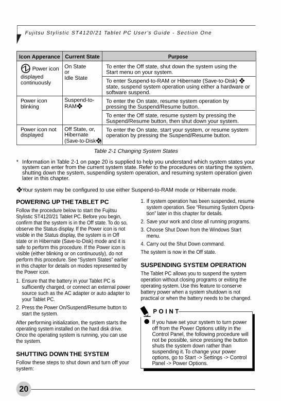
Icon Apperance
Power icon
displayedcontinuously
Power iconblinking
Power icon notdisplayed
Purpose
To enter the Off state, shut down the system using theStart menu on your system.
To enter Suspend-to-RAM or Hibernate (Save-to-Disk) ❖state, suspend system operation using either a hardware orsoftware suspend.
To enter the On state, resume system operation bypressing the Suspend/Resume button.
To enter the Off state, resume system by pressing theSuspend/Resume button, then shut down your system.
To enter the On state, start your system, or resume systemoperation by pressing the Suspend/Resume button.
Current State
On StateorIdle State
Suspend-to-RAM❖
Off State, or,Hibernate(Save-to-Disk❖ )
Table 2-1 Changing System States
* Information in Table 2-1 on page 20 is supplied to help you understand which system states yoursystem can enter from the current system state. Refer to the procedures on starting the system,shutting down the system, suspending system operation, and resuming system operation givenlater in this chapter.
❖ Your system may be configured to use either Suspend-to-RAM mode or Hibernate mode.
POWERING UP THE TABLET PCFollow the procedure below to start the FujitsuStylistic ST4120/21 Tablet PC. Before you begin,confirm that the system is in the Off state. To do so,observe the Status display. If the Power icon is notvisible in the Status display, the system is in Offstate or in Hibernate (Save-to-Disk) mode and it issafe to perform this procedure. If the Power icon isvisible (either blinking or on continuously), do notperform this procedure. See “System States” earlierin this chapter for details on modes represented bythe Power icon.
1. Ensure that the battery in your Tablet PC issufficiently charged, or connect an external powersource such as the AC adapter or auto adapter toyour Tablet PC.
2. Press the Power On/Suspend/Resume button tostart the system.
After performing initialization, the system starts theoperating system installed on the hard disk drive.Once the operating system is running, you can usethe system.
SHUTTING DOWN THE SYSTEMFollow these steps to shut down and turn off yoursystem:
1. If system operation has been suspended, resumesystem operation. See “Resuming System Opera-tion” later in this chapter for details.
2. Save your work and close all running programs.
3. Choose Shut Down from the Windows Startmenu.
4. Carry out the Shut Down command.
The system is now in the Off state.
SUSPENDING SYSTEM OPERATIONThe Tablet PC allows you to suspend the systemoperation without closing programs or exiting theoperating system. Use this feature to conservebattery power when a system shutdown is notpractical or when the battery needs to be changed.
If you have set your system to turn poweroff from the Power Options utility in theControl Panel, the following procedure willnot be possible, since pressing the buttonshuts the system down rather thansuspending it. To change your poweroptions, go to Start -> Settings -> ControlPanel -> Power Options.
Alb Active2 (17-28) 25/3/03, 12:01 PM20
Using Your S ty l i s t i c ST4120/21
21
To suspend system operation:
1. Press the Suspend/Resume button, or carry outthe Standby command from your operatingsystem or power management program.(If your system is configured to suspendoperation using Hibernate (Save-to-Disk)mode, which is explained later in thisprocedure, a message is displayed while datais saved to your hard disk.)
2. The Power icon either flashes (Suspend-to-RAM) or is not displayed (Hibernate) whensystem operation is suspended, dependingon how your system is configured. At thispoint, programs that were running arestopped, active data is saved, and the systementers one of two different low-power states,or suspend modes, as explained in thefollowing paragraphs.
3. Observe the Power icon in the Status displayto determine which suspend mode yoursystem is using.
• Power icon is blinking: Suspend-to-RAM mode.
In this mode, active data is saved bymaintaining power to RAM while most othersystem components are powered off. TheBattery Gauge icon in the Status displayindicates the battery charge level.
• Power icon is not displayed: Hibernate(Save-to-Disk) mode.
In this mode, active data is stored on the harddisk drive and power usage is reduced to thesame level used in the Off state. When thesystem is in Hibernate mode, the BatteryGauge icon is not visible in the Status display.In this mode, there is no danger of losingdata if battery power is lost.
If you have successfully performed thisprocedure, system operation is nowsuspended. Refer to “Resuming System
Operation” later in this chapter to resumesystem operation. Also, note the followingwith regard to suspending system operation:
• You can remove the battery while the system isin Suspend-to-RAM or Hibernate modes inorder to install a charged battery. To preventlosing unsaved data, wait until system operationhas suspended before you remove the battery.Note that after you remove the battery, you haveapproximately five minutes to replace it with anew battery or to plug in a power supply beforethe bridge battery is depleted.
• Your system may be configured to suspendoperation automatically after a period ofinactivity.
• Your system may be configured to enterHibernate mode automatically after a periodof time in Suspend-to-RAM mode.
• The system uses a small amount of batterypower when in Suspend-to-RAM mode.Eventually, the battery will become fullydischarged.
• If the battery charge drops to a Low-BatteryWarning level while the system is running, thesystem will beep periodically. If this occurs,suspend system operation, shut down thesystem, or attach an external power source,such as the AC adapter, to the Tablet PC.
• If the battery charge drops to a Critically Lowlevel while the system is running, the systemis forced into a pre-selected mode (Suspend-to-RAM or Hibernate). If this occurs, you musteither install a charged battery, or connect anappropriate external power source such asthe AC adapter before you can resumesystem operation. (If the battery charge dropsto a Critically Low level while the system is inSuspend-to-RAM mode, the system stays inSuspend-to- RAM mode until power isrestored or totally dissipated.)
• Suspending system operation interrupts datacommunications; therefore, some programsmay block the system from suspending toprevent an interruption.
If you are replacing the battery, wait untilsystem operation is suspended and thepower icon is flashing before you remove thebattery. Failure to do so could result in loss ofyour unsaved data. (Note that if the ResumeOn LAN function is enabled in the BIOS setup,you should not remove the battery unless thesystem is shut down. When Resume ON LANis enabled, the bridge battery is disabled inorder to optimize battery life.)
If you will not be using the system for anextended period of time, shut down thesystem rather than using Suspend-to-RAM mode.
Alb Active2 (17-28) 25/3/03, 12:01 PM21
22
Fuj i t su Sty l i s t i c ST4120/21 Table t PC User ’s Gu ide - Sec t ion One
• The suspend action of the Suspend/Resumebutton may be disabled to prevent accidentalinterruption. If this is the case, pressing theSuspend/Resume button will not suspendsystem operation as described here. (In thiscase, suspend mode can only be achievedusing the system software). Contact yourlocal help desk or reseller if your systemconfiguration is not suitable.
• If your system is equipped with a PC Card thatallows you to connect to a wired or wirelessnetwork, you may be logged off the networkafter a period of inactivity while systemoperation is suspended. Contact your networkadministrator or help desk for details on log-offparameters for your network.
RESUMING SYSTEM OPERATIONTo resume system operation from eitherSuspend-to-RAM or Hibernate modes, press theSuspend/Resume button.
• From Suspend-to-RAM modeStatus lights indicate that the system state ischanging. It may take up to a minute before thesystem returns to the On state and systemoperation resumes. Note that the display turns onshortly before the pen becomes active due to thepower-up sequences observed by the system.
• From Hibernate (Save-to-Disk) modeActive data is read from the hard disk drive,and the system returns to the On state after ashort time.
• Use the system as you normally would oncesystem operation resumes.
All programs resume at the point where executionstopped when system operation was suspended.
Note that power to several systemcomponents must be restored beforesystem operation resumes. Allowsufficient time for system operation toresume before attempting to use thesystem. If your system uses Hibernatemode, it will take longer to resumeoperation as compared to using Suspend-to-RAM mode. Time is needed to readdata from the hard disk drive.
Depending upon whether you arerunning your system on battery or ACpower, the default screen brightnesssettings will be different. The screenbrightness default for running on batteryis lower than that on AC power in orderto optimize battery life.
ADJUSTING THE DISPLAY BRIGHTNESSThere are two ways to adjust the brightness ofyour display:
• Click the Tablet icon in the system tray at thebottom right of the screen. (When the cursor ison top of the icon, a message stating “Changetablet and pen settings” is displayed.) Whenthe Tablet and Pen Settings window appears,select the Display tab, and move the ScreenBrightness slider to change the brightness.
• Click Start -> Settings -> Control Panel ->Tablet and Pen Settings. Select the Display tab,and move the Screen Brightness slider tochange the brightness.
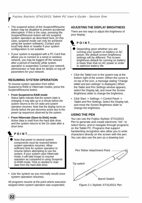
USING THE PENYou can use the Fujitsu Stylistic ST4120/21Pen to generate and create electronic “ink”, toselect items, and to navigate through programson the Tablet PC. Programs that supporthandwriting recognition also allow you to writecharacters directly on the screen with the pen.You can also use the pen as a drawing tool.
Tip switch
Barrel Switch
Pen Tether Attachment Point
Figure 2-1 Stylistic ST4120/21 Pen
Alb Active2 (17-28) 25/3/03, 12:01 PM22
Using Your S ty l i s t i c ST4120/21
23
• Ensure that a screen protector isinstalled on the Tablet PC screen beforeyou use the pen. The warranty does notcover a screen that is scratched as aresult of not using a screen protector.
• Use only the pen provided with yourTablet PC. Do not use substitutes thatwere not designed for the FujitsuStylistic ST4120/21 Tablet PC. Damagecaused by using an instrument otherthan the provided pen is not covered bythe system warranty.
The Stylistic ST4120/21 pen is a sophisticated,high-quality electronic instrument that can bedamaged if used improperly. Treat the pen asyou would any precision device. The followinglist contains guidelines for proper pen handling:
Do not gesture with the pen, use it as apointer, or tap it on surfaces other than theTablet PC screen.Do not try to turn the thumb grip on the pen;it is designed for inserting and removing thepen from the pen holder and for attaching apen tether.Never store the pen with the tip bearing theweight of the pen (e.g., sitting tip down in apencil cup). Storing the pen tip down coulddistort the internal mechanism over a periodof time (especially in higher temperatures),causing the tip to act as if it is alwaysdepressed. To avoid damage, the pen shouldbe stored in the pen holder when not in use.
The screen reacts when the pen tip is approximately1/8 inch (3-5mm) from the screen. The pen hasthree switches: a tip switch and a barrel buttontoggle switch with switches at both ends. Whenactivated, the tip switch corresponds to the leftmouse button, and the front toggle (closest to thepen tip) barrel button switch, when used incombination with the tip switch, corresponds to theright mouse button. The rear toggle of the barrelbutton switch acts as an electronic ink “eraser”.
Here are some hints that may help you use thepen more effectively:
• To activate the tip switch, tap or hold thepen tip against the screen.
• To activate the barrel button switch, pressand hold the end of the button you wish to use(front toggle is the right mouse button switch;the rear toggle acts as an electronic “eraser”.
• To move the cursor, hold the pen tip within1/8 inch (3 - 5mm) from the screen andmove the pen.
• To start a program, double-tap the pen tip(tap the pen tip twice rapidly) on the programicon as you would double-click a mouse.
• To select an object, tap the pen tip on theobject once.
• To “double-click” an object, tap twice onthe object quickly.
• To move, or “drag”, an object on thescreen, place the pen tip directly over theobject, then as you hold the pen tip againstthe screen, move the pen.
CALIBRATING THE PENFor information about calibrating your pen, refer tothe literature that came with the operating system.
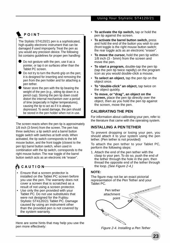
INSTALLING A PEN TETHERTo prevent dropping or losing your pen, youshould attach it to your system using the pentether. (Pen tether is not provided)To attach the pen tether to your Tablet PC,perform the following steps:1. Attach the end of the pen tether with the
clasp to your pen. To do so, push the end ofthe tether through the hole in the pen, thenthread the opposite end of the tether throughthe loop. (See Figure 2-4.)
NOTE:The figure may not be an exact pictorialrepresentation of the Pen Tether and yourTablet PC.
Figure 2-4. Installing a Pen Tether
Pen tetherattachment
point
Alb Active2 (17-28) 26/3/03, 3:01 PM23
24
Fuj i t su Sty l i s t i c ST4120/21 Table t PC User ’s Gu ide - Sec t ion One
2. Attach the other end of the pen tether to theattachment point on your Tablet PC.
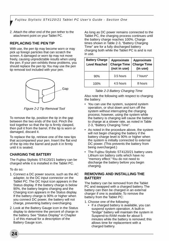
REPLACING THE PEN TIPWith use, the pen tip may become worn or maypick up foreign particles that can scratch thescreen. A damaged or worn tip may not movefreely, causing unpredictable results when usingthe pen. If your pen exhibits these problems, youshould replace the pen tip. You may use the pentip removal tool included with your pen.
To remove the tip, position the tip in the gapbetween the two ends of the tool. Pinch thetool together so that the tip is firmly clasped,then pull it from the barrel. If the tip is worn ordamaged, discard it.
To replace the tip, retrieve one of the new tipsthat accompanied your pen. Insert the flat endof the tip into the barrel and push it in firmlyuntil it is seated.
CHARGING THE BATTERYThe Fujitsu Stylistic ST4120/21 battery can becharged while it is installed in the Tablet PC.
To do so:
1. Connect a DC power source, such as the ACadapter, to the DC input connector on theTablet PC. The DC Input icon appears in theStatus display. If the battery charge is below90%, the battery begins charging and theCharging icon appears in the Status display.If the battery charge is 90% or higher whenyou connect DC power, the battery will notcharge, preventing battery overcharging.
2. Look at the Battery Gauge icon in the Statusdisplay to determine the percent of charge inthe battery. See “Status Display” in Chapter1 of this manual for a description of theBattery Gauge icon.
Figure 2-2 Tip Removal Tool
Gap
As long as DC power remains connected to theTablet PC, the charging process continues untilthe battery charge reaches 100%. Chargetimes shown in Table 2-3, “Battery ChargingTime" are for a fully discharged batterycharging both while the Tablet PC is and is notin use.
ApproximateCharge Time(not in use)
3.5 hours
4.5 hours
ApproximateCharge Time
(in use)
7 hours*
8 hours
Table 2-3 Battery Charging Time
Battery ChargeLevel Reached
90%
100%
Also note the following with respect to chargingthe battery:• You can use the system, suspend system
operation, or shut down and turn off thesystem without interrupting the chargingprocess; however, using the system whilethe battery is charging will cause the batteryto charge at a slower rate, as noted in Table2-3, “Battery Charging Time".
• As noted in the procedure above, the systemwill not begin charging the battery if thebattery charge level is 90% or higher whenthe system is initially connected to externalDC power. (This prevents the battery frombeing overcharged.)
• The Fujitsu Stylistic ST4120/21 battery usesLithium ion battery cells which have no“memory effect.” You do not need todischarge the battery before you begincharging.
REMOVING AND INSTALLING THEBATTERYThe battery can be removed from the TabletPC and swapped with a charged battery. Thebattery can then be charged in an externalcharger if one is available. To remove thebattery from the Tablet PC:1. Choose one of the following:
• If a charged battery is available, you cansuspend system operation. A built-in“bridge” battery will maintain the system inSuspend-to-RAM mode for about 5minutes while the battery is removed; thisallows time for replacement with acharged battery.
Alb Active2 (17-28) 25/3/03, 12:01 PM24
Using Your S ty l i s t i c ST4120/21
25
Once the battery is installed, you can resumesystem operation or start and use your systemnormally.
TIPS FOR CONSERVING BATTERYPOWERYou can extend the charge life of your batteryby conserving battery power. (Your results mayvary depending on your application and howthe system is configured.) Here are somesuggestions to help you conserve batterypower:• Use an external power source such as the
AC adapter whenever the system is docked.• Suspend system operation if you know that
you won’t be using the system for a while.• Shut down the system if you won’t be using
the system for an extended period of time.• Use power management (available on the
desktop) to help you conserve powerautomatically.
• Battery life is dependent upon the operatingsystem, power settings, and applications inuse.
Operation of the Bridge Battery
When installed in the Tablet PC, the batteryprovides power to some system components—even when the system is in the Off state. Whenthe battery is removed, power is supplied tothese components by a “bridge” battery that isbuilt into the Tablet PC.
The bridge battery is not designed for long-term operation. To maintain the bridge batteryproperly, observe the following measures:
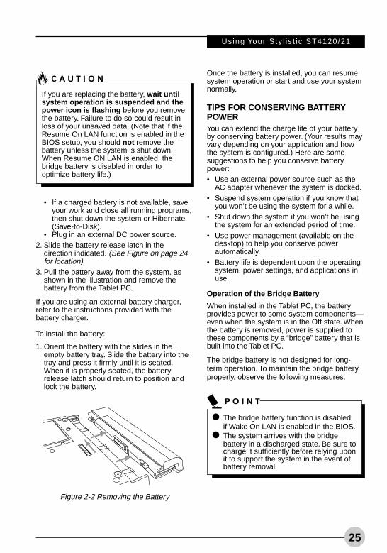
Figure 2-2 Removing the Battery
• If a charged battery is not available, saveyour work and close all running programs,then shut down the system or Hibernate(Save-to-Disk).
• Plug in an external DC power source.2. Slide the battery release latch in the
direction indicated. (See Figure on page 24for location).
3. Pull the battery away from the system, asshown in the illustration and remove thebattery from the Tablet PC.
If you are using an external battery charger,refer to the instructions provided with thebattery charger.
To install the battery:
1. Orient the battery with the slides in theempty battery tray. Slide the battery into thetray and press it firmly until it is seated.When it is properly seated, the batteryrelease latch should return to position andlock the battery.
If you are replacing the battery, wait untilsystem operation is suspended and thepower icon is flashing before you removethe battery. Failure to do so could result inloss of your unsaved data. (Note that if theResume On LAN function is enabled in theBIOS setup, you should not remove thebattery unless the system is shut down.When Resume ON LAN is enabled, thebridge battery is disabled in order tooptimize battery life.)
The bridge battery function is disabledif Wake On LAN is enabled in the BIOS.The system arrives with the bridgebattery in a discharged state. Be sure tocharge it sufficiently before relying uponit to support the system in the event ofbattery removal.
Alb Active2 (17-28) 25/3/03, 12:01 PM25
26
Fuj i t su Sty l i s t i c ST4120/21 Table t PC User ’s Gu ide - Sec t ion One
Figure 2-4 Removing a PC Card
Figure 2-3 Installing a PC Card
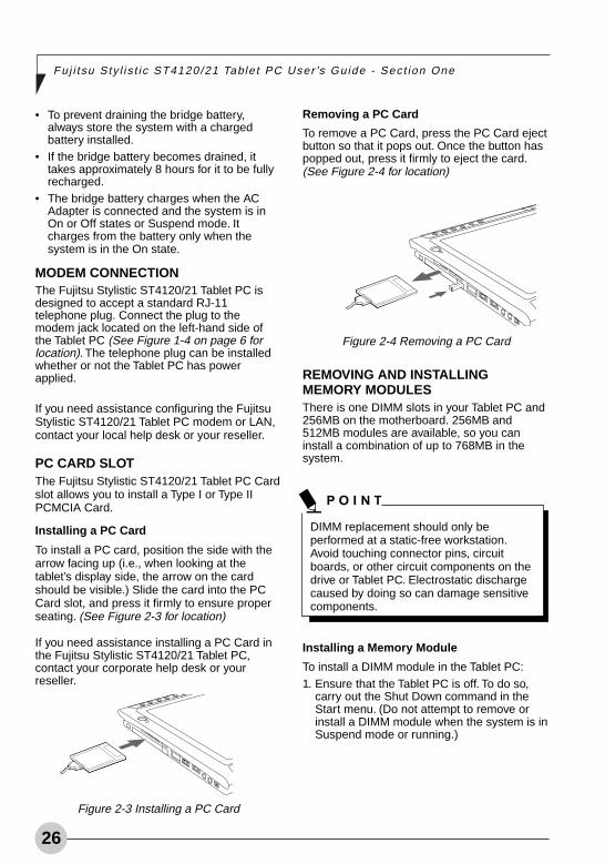
Removing a PC Card
To remove a PC Card, press the PC Card ejectbutton so that it pops out. Once the button haspopped out, press it firmly to eject the card.(See Figure 2-4 for location)
• To prevent draining the bridge battery,always store the system with a chargedbattery installed.
• If the bridge battery becomes drained, ittakes approximately 8 hours for it to be fullyrecharged.
• The bridge battery charges when the ACAdapter is connected and the system is inOn or Off states or Suspend mode. Itcharges from the battery only when thesystem is in the On state.
MODEM CONNECTIONThe Fujitsu Stylistic ST4120/21 Tablet PC isdesigned to accept a standard RJ-11telephone plug. Connect the plug to themodem jack located on the left-hand side ofthe Tablet PC (See Figure 1-4 on page 6 forlocation). The telephone plug can be installedwhether or not the Tablet PC has powerapplied.
If you need assistance configuring the FujitsuStylistic ST4120/21 Tablet PC modem or LAN,contact your local help desk or your reseller.
PC CARD SLOTThe Fujitsu Stylistic ST4120/21 Tablet PC Cardslot allows you to install a Type I or Type IIPCMCIA Card.
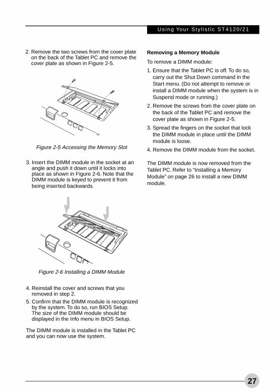
Installing a PC Card
To install a PC card, position the side with thearrow facing up (i.e., when looking at thetablet’s display side, the arrow on the cardshould be visible.) Slide the card into the PCCard slot, and press it firmly to ensure properseating. (See Figure 2-3 for location)
If you need assistance installing a PC Card inthe Fujitsu Stylistic ST4120/21 Tablet PC,contact your corporate help desk or yourreseller.
REMOVING AND INSTALLINGMEMORY MODULESThere is one DIMM slots in your Tablet PC and256MB on the motherboard. 256MB and512MB modules are available, so you caninstall a combination of up to 768MB in thesystem.
DIMM replacement should only beperformed at a static-free workstation.Avoid touching connector pins, circuitboards, or other circuit components on thedrive or Tablet PC. Electrostatic dischargecaused by doing so can damage sensitivecomponents.
Installing a Memory Module
To install a DIMM module in the Tablet PC:1. Ensure that the Tablet PC is off. To do so,
carry out the Shut Down command in theStart menu. (Do not attempt to remove orinstall a DIMM module when the system is inSuspend mode or running.)
Alb Active2 (17-28) 25/3/03, 12:01 PM26
Using Your S ty l i s t i c ST4120/21
27
Figure 2-6 Installing a DIMM Module
3. Insert the DIMM module in the socket at anangle and push it down until it locks intoplace as shown in Figure 2-6. Note that theDIMM module is keyed to prevent it frombeing inserted backwards.
4. Reinstall the cover and screws that youremoved in step 2.
5. Confirm that the DIMM module is recognizedby the system. To do so, run BIOS Setup.The size of the DIMM module should bedisplayed in the Info menu in BIOS Setup.
The DIMM module is installed in the Tablet PCand you can now use the system.
Removing a Memory Module
To remove a DIMM module:
1. Ensure that the Tablet PC is off. To do so,carry out the Shut Down command in theStart menu. (Do not attempt to remove orinstall a DIMM module when the system is inSuspend mode or running.)
2. Remove the screws from the cover plate onthe back of the Tablet PC and remove thecover plate as shown in Figure 2-5.
3. Spread the fingers on the socket that lockthe DIMM module in place until the DIMMmodule is loose.
4. Remove the DIMM module from the socket.
The DIMM module is now removed from theTablet PC. Refer to “Installing a MemoryModule” on page 26 to install a new DIMMmodule.
Figure 2-5 Accessing the Memory Slot
2. Remove the two screws from the cover plateon the back of the Tablet PC and remove thecover plate as shown in Figure 2-5.
Alb Active2 (17-28) 26/3/03, 3:02 PM27
28
Fuj i t su Sty l i s t i c ST4120/21 Table t PC User ’s Gu ide - Sec t ion One
Alb Active2 (17-28) 25/3/03, 12:01 PM28

29
Care andMaintenance
33333
Alb Active3 (29-34) 25/3/03, 12:02 PM29

30
Fuj i t su Sty l i s t i c ST4120/21 Table t PC User ’s Gu ide - Sec t ion One
Alb Active3 (29-34) 25/3/03, 12:02 PM30
31
Care and Main tenance
Care and MaintenanceThis chapter gives you pointers on how to carefor and maintain your Fujitsu Stylistic ST4120/21 Tablet PC.
PROTECTING THE DISPLAY SCREENThe Fujitsu Stylistic ST4120/21 Tablet PC isdesigned to provide you with years of service.Using a screen protector will help ensure thatthe screen remains as clear as possible. Wheninstalled, the screen protector becomes adurable, replaceable writing surface thatprotects the display screen from abrasion.
To install a new screen protector on your Tablet PC:
1. If a screen protector is already installed onthe display screen, remove it before installingthe new screen protector.
The screen protector is held onto the displayscreen surface by a thin strip of adhesivearound the edges. A notch in one corner ofthe screen protector allows you to slide yourfingernail under the screen protector for easyremoval.
2. Clean the display by wiping the screengently using a soft cotton cloth dampenedwith isopropyl alcohol. Ensure that all residuehas been removed from the screen beforeapplying a new screen protector.
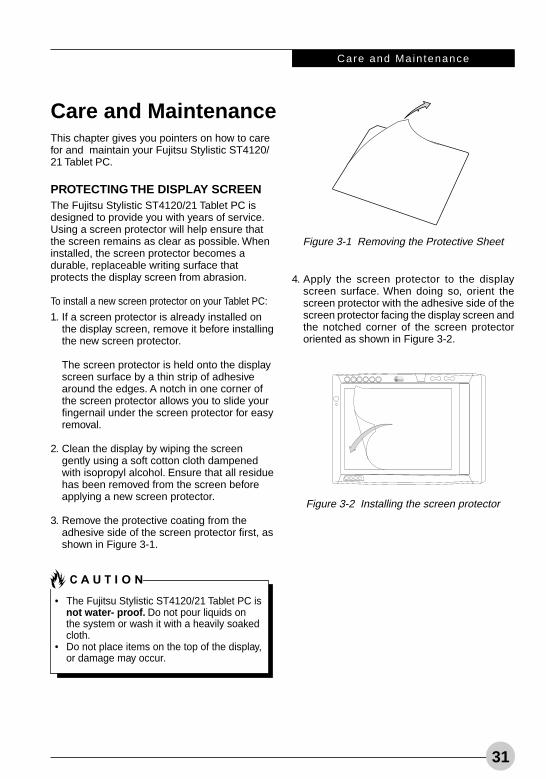
3. Remove the protective coating from theadhesive side of the screen protector first, asshown in Figure 3-1.
Figure 3-1 Removing the Protective Sheet
Figure 3-2 Installing the screen protector
• The Fujitsu Stylistic ST4120/21 Tablet PC isnot water- proof. Do not pour liquids onthe system or wash it with a heavily soakedcloth.
• Do not place items on the top of the display,or damage may occur.
4. Apply the screen protector to the displayscreen surface. When doing so, orient thescreen protector with the adhesive side of thescreen protector facing the display screen andthe notched corner of the screen protectororiented as shown in Figure 3-2.
Alb Active3 (29-34) 25/3/03, 12:02 PM31
32
Fuj i t su Sty l i s t i c ST4120/21 Table t PC User ’s Gu ide - Sec t ion One
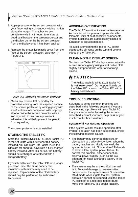
5. Apply pressure to the screen protector withyour finger using a continuous wiping motionalong the edges. The adhesive setscompletely within 48 hours. To ensure agood seal between the screen protector andthe display, do not lift the screen protectorfrom the display once it has been applied.
6. Remove the protective plastic cover from theface of the screen protector, as shown inFigure 3-3.
7. Clean any residue left behind by theprotective coating from the exposed surfaceof the screen protector by wiping gently witha soft cotton cloth dampened with isopropylalcohol. Wipe the screen protector with asoft dry cloth to remove any low-tackadhesive; this will help prevent the pen tipfrom squeaking.
The screen protector is now installed.
STORING THE TABLET PCStore the Fujitsu Stylistic ST4120/21 Tablet PCin the Off state with a fully charged batteryinstalled. You can store the Tablet PC in theOff state for about 30 days with a fully chargedbattery installed. After this period, the batteryshould be recharged or replaced with acharged battery.
If you intend to store the Tablet PC for a longerperiod of time, the small battery thatmaintains system time may need to bereplaced. Replacement of the clock batteryshould only be performed by authorizedtechnicians.
Figure 3-3 Installing the screen protector
AVOIDING OVERHEATINGThe Tablet PC monitors its internal temperature.As the internal temperature approaches thetolerable limits of heat-sensitive components,system functions are automatically limited orturned off to prevent damage.
To avoid overheating the Tablet PC, do notobstruct the air vents on the top and bottomedges of the Tablet PC.
CLEANING THE DISPLAY SCREENTo clean the Tablet PC display screen, wipe thescreen surface gently using a soft cotton clothslightly dampened with water or isopropylalcohol.
TROUBLESHOOTINGSolutions to some common problems aredescribed in the following sections. If you areexperiencing a problem with your Tablet PCthat you cannot solve by taking the actionsdescribed, contact your local help desk or yourreseller for further assistance.
System Will Not Resume Operation
If the system will not resume operation aftersystem operation has been suspended, checkthe following possible causes:
• The battery may either be defective, ordischarged to a critically low level. When thebattery reaches a critically low level, thesystem is forced into Suspend-to-RAM modeto avoid a total system power failure. Tocorrect this problem, either connect anexternal power supply (such as the ACadapter), or install a charged battery in theTablet PC.
• The system may be at the critical thermallimit. To avoid damage to heat-sensitivecomponents, the system enters Suspend-to-RAM mode when it gets too hot. Systemoperation cannot be resumed until the TabletPC cools off to a tolerable temperature.Move the Tablet PC to a cooler location.
The Fujitsu Stylistic ST4120/21 Tablet PCis not waterproof. Do not pour liquids onthe Tablet PC or wash the Tablet PC with aheavily soaked cloth.
Alb Active3 (29-34) 25/3/03, 12:02 PM32
33
Care and Main tenance
Display Screen Blank or Difficult to Read
If the display screen on your Tablet PC appearsblank or is unreadable, confirm that the systemis running (the Power icon is displayedcontinuously on the Status display), and checkthe following:
• The system brightness may be set too low,causing the screen to appear too dark. Tochange system brightness, press the Fnbutton twice to open the Fujitsu menu.Brightness can be adjusted from the menu.
• The video timeout may have expired. Tap onthe display screen to reactivate the display.Note that this is a normal, power-savingfeature.
Cursor Is Not Tracking Pen
If the cursor on the screen appears to be misalignedwith the pen or is not accurately tracking the pen,calibrate the pen. See “To Calibrate the Pen” onpage 23 for more information.
Infrared Data Transfer Is Not Working
If you are experiencing problems transferringdata over the system’s infrared interface, notethe following:
• Can the IrDA port on the Tablet PC “see” theIrDA port on the other device? A direct line-of- sight path must exist between the IrDAport on the Tablet PC and the IrDA port onthe other device.
• The distance between the two devices mustnot be more than 3 feet.
• The viewing angle from the IrDA port on theTablet PC must not be more than 15 degreesfrom a center line between the IrDA port onthe Tablet PC and the IrDA port on the otherdevice.
• The device with which you are trying tocommunicate must be compliant with theIrDA Standard Revision 1.1 (or 1.0).
• It may be necessary for both computers tobe using the same network connectionprotocols.
Tablet PC is Not Responding to the Pen
If the Tablet PC does not respond to the pen,connect an external keyboard to the system tosee if it responds to keyboard commands. If thesystem doesn’t respond to a keyboard, theapplication or system may have crashed, and itmay be necessary to reset the system. If thesystem responds to a keyboard but not to apen, contact your local help desk or reseller forfurther assistance.
Speaker/Headphone Volume Too Low
If the audio volume on your Tablet PC speakeror external headphones is too low, check thefollowing:
• Ensure that the speaker (or headphoneoutput if using headphones) is enabled. Todo so, open the Control Panel and double-click on the Sounds and Audio Devices icon.Select the proper tab, and increase thevolume using the slider bar. (If you aren’tgetting any sound, uncheck the Mute box if itis checked.)
• Press the Fn button twice to open the Fujitsumenu. Volume can be adjusted from themenu.
• Ensure that the mute box in the systemvolume control (accessible from the systemtray) is not set.
• Ensure that any volume control in your audiosoftware is set to an audible level.
Configuring Peripheral Interfaces
Certain peripheral devices can be disabledduring the BIOS Setup. If the peripheralinterface you want to use does not appear tobe working with your peripheral device, ensurethat it is enabled in the BIOS. Contact yourlocal help desk or reseller if you needassistance using BIOS Setup.
Alb Active3 (29-34) 25/3/03, 12:02 PM33

34
Fuj i t su Sty l i s t i c ST4120/21 Table t PC User ’s Gu ide - Sec t ion One
Alb Active3 (29-34) 25/3/03, 12:02 PM34
35
Specifications
44444
Alb Active4 (35-38) 25/3/03, 12:03 PM35

36
Fuj i t su Sty l i s t i c ST4120/21 Table t PC User ’s Gu ide - Sec t ion One
Alb Active4 (35-38) 25/3/03, 12:03 PM36
System Spec i f i ca t ions
37
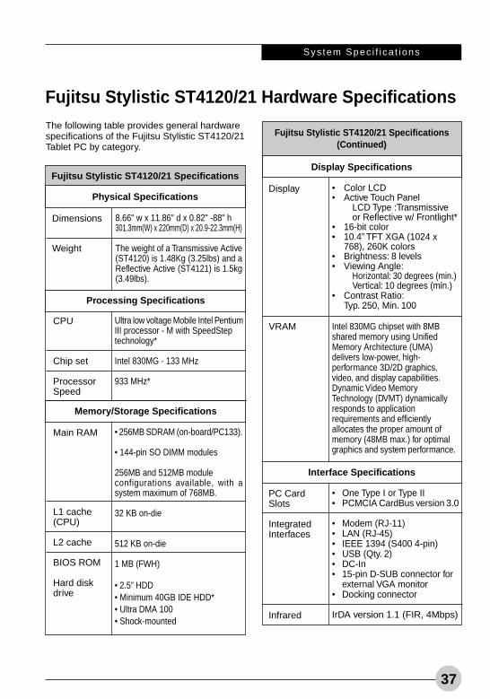
Fujitsu Stylistic ST4120/21 Hardware Specifications
Fujitsu Stylistic ST4120/21 Specifications
8.66" w x 11.86" d x 0.82" -88" h301.3mm(W) x 220mm(D) x 20.9-22.3mm(H)
The weight of a Transmissive Active(ST4120) is 1.48Kg (3.25lbs) and aReflective Active (ST4121) is 1.5kg(3.49lbs).
The following table provides general hardwarespecifications of the Fujitsu Stylistic ST4120/21Tablet PC by category.
Physical Specifications
Dimensions
Weight
Processing Specifications
Ultra low voltage Mobile Intel PentiumIII processor - M with SpeedSteptechnology*
Intel 830MG - 133 MHz
933 MHz*
CPU
Chip set
ProcessorSpeed
Memory/Storage Specifications
• 256MB SDRAM (on-board/PC133).
• 144-pin SO DIMM modules
256MB and 512MB moduleconfigurations available, with asystem maximum of 768MB.
32 KB on-die
512 KB on-die
1 MB (FWH)
• 2.5” HDD• Minimum 40GB IDE HDD*• Ultra DMA 100• Shock-mounted
Main RAM
L1 cache(CPU)
L2 cache
BIOS ROM
Hard diskdrive
Fujitsu Stylistic ST4120/21 Specifications(Continued)
• Color LCD• Active Touch Panel
LCD Type :Transmissiveor Reflective w/ Frontlight*
• 16-bit color• 10.4” TFT XGA (1024 x
768), 260K colors• Brightness: 8 levels• Viewing Angle:
Horizontal: 30 degrees (min.)Vertical: 10 degrees (min.)
• Contrast Ratio:Typ. 250, Min. 100
Intel 830MG chipset with 8MBshared memory using UnifiedMemory Architecture (UMA)delivers low-power, high-performance 3D/2D graphics,video, and display capabilities.Dynamic Video MemoryTechnology (DVMT) dynamicallyresponds to applicationrequirements and efficientlyallocates the proper amount ofmemory (48MB max.) for optimalgraphics and system performance.
Display Specifications
Display
VRAM
Interface Specifications
• One Type I or Type II• PCMCIA CardBus version 3.0
• Modem (RJ-11)• LAN (RJ-45)• IEEE 1394 (S400 4-pin)• USB (Qty. 2)• DC-In• 15-pin D-SUB connector for
external VGA monitor• Docking connector
IrDA version 1.1 (FIR, 4Mbps)
PC CardSlots
IntegratedInterfaces
Infrared
Alb Active4 (35-38) 25/3/03, 12:03 PM37
38
Fuj i t su Sty l i s t i c ST4120/21 Table t PC User ’s Gu ide - Sec t ion One
* The specifications for your particular modelmay vary. To determine the specifications foryour system, please visit our web site at:www.fujitsu-pc-asia.com
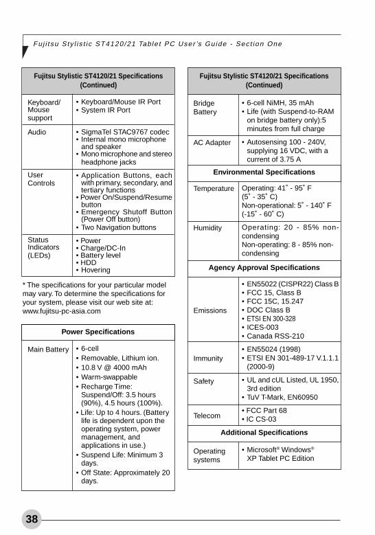
Fujitsu Stylistic ST4120/21 Specifications(Continued)
• Keyboard/Mouse IR Port• System IR Port
• SigmaTel STAC9767 codec• Internal mono microphone
and speaker• Mono microphone and stereo
headphone jacks
• Application Buttons, eachwith primary, secondary, andtertiary functions
• Power On/Suspend/Resumebutton
• Emergency Shutoff Button(Power Off button)
• Two Navigation buttons
• Power• Charge/DC-In• Battery level• HDD• Hovering
Keyboard/Mousesupport
Audio
UserControls
StatusIndicators(LEDs)
Power Specifications
• 6-cell• Removable, Lithium ion.• 10.8 V @ 4000 mAh• Warm-swappable• Recharge Time:
Suspend/Off: 3.5 hours(90%), 4.5 hours (100%).
• Life: Up to 4 hours. (Batterylife is dependent upon theoperating system, powermanagement, andapplications in use.)
• Suspend Life: Minimum 3days.
• Off State: Approximately 20days.
Main Battery
Fujitsu Stylistic ST4120/21 Specifications(Continued)
• 6-cell NiMH, 35 mAh• Life (with Suspend-to-RAM
on bridge battery only):5minutes from full charge
• Autosensing 100 - 240V,supplying 16 VDC, with acurrent of 3.75 A
Operating: 41˚ - 95˚ F(5˚ - 35˚ C)Non-operational: 5˚ - 140˚ F(-15˚ - 60˚ C)
Operating: 20 - 85% non-condensingNon-operating: 8 - 85% non-condensing
• EN55022 (CISPR22) Class B• FCC 15, Class B• FCC 15C, 15.247• DOC Class B• ETSI EN 300-328• ICES-003• Canada RSS-210
• EN55024 (1998)• ETSI EN 301-489-17 V.1.1.1
(2000-9)
• UL and cUL Listed, UL 1950,3rd edition
• TuV T-Mark, EN60950
• FCC Part 68• IC CS-03
• Microsoft® Windows®
XP Tablet PC Edition
BridgeBattery
AC Adapter
Temperature
Humidity
Emissions
Immunity
Safety
Telecom
Operatingsystems
Environmental Specifications
Agency Approval Specifications
Additional Specifications
Alb Active4 (35-38) 25/3/03, 3:45 PM38

39
Agency Notices
55555
Alb Active5 (39-44) 25/3/03, 12:03 PM39

40
Fuj i t su Sty l i s t i c ST4120/21 Table t PC User ’s Gu ide - Sec t ion One
Alb Active5 (39-44) 25/3/03, 12:03 PM40
Agency Not ices
41
Regulatory Information
NOTICEChanges or modifications not expresslyapproved by Fujitsu could void this user’sauthority to operate the equipment.
FCC NOTICESNotice to Users of Radios and TelevisionThese limits are designed to provide reasonableprotection against harmful interference in aresidential installation. This equipment generates,uses, and can radiate radio frequency energyand, if not installed and used in accordance withthe instructions, may cause harmful interferenceto radio communications. However, there is noguarantee that interference will not occur in aparticular installation. If this equipment doescause harmful interference to radio or televisionreception, which can be determined by turningthe equipment off and on, the user is encouragedto try to correct the interference by one or more ofthe following measures:
• Reorient or relocate the receiving antenna.
• Increase the separation between theequipment and receiver.
• Connect the equipment into an outlet that ison a different circuit than the receiver.
• Consult the dealer or an experienced radio/TV technician for help.
Shielded interconnect cables must beemployed with this equipment to ensurecompliance with the pertinent RF emissionlimits governing this device.
Notice to Users of the US Telephone NetworkYour Tablet PC may be supplied with aninternal modem which complies with Part 68 ofthe FCC rules. On the system is a label thatcontains the FCC Registration Number and theRinger Equivalence Number (REN) for thisequipment among other information. Ifrequested, the user must provide theirtelephone company with the followinginformation:
1. The telephone number to which thecomputer is connected.
2. The Ringer Equivalence Number (REN) forthis equipment.
3. The equipment requires a standard modularjack type USOC RJ-11C which is FCC Part68 compliant.
4. The FCC Registration Number.
This equipment is designed to be connected tothe telephone network or premises wiringusing a standard modular jack type USOC RJ-11C which is FCC Part 68 compliant and a linecord between the modem and the telephonenetwork with a minimum of 26AWG.
The REN is used to determine the number ofdevices that you may connect to yourtelephone line and still have all of thosedevices ring when your number is called. Toomany devices on one line may result in failureto ring in response to an incoming call. In most,but not all, areas the sum of the RENs of all ofthe devices should not exceed five (5). To becertain of the number of devices you mayconnect to your line, as determined by theRENs, contact your local telephone company.
If this equipment causes harm to the telephonenetwork, your telephone company maydiscontinue your service temporarily. Ifpossible, they will notify you in advance. Ifadvance notice is not practical they will notifyyou as soon as possible. You will also beadvised of your right to file a complaint with theFCC.
This fax modem also complies with faxbranding requirements per FCC Part 68.
Your telephone company will probably ask youto disconnect this equipment from thetelephone network until the problem iscorrected and you are sure that the equipmentis not malfunctioning. This equipment may notbe used on coin-operated telephones providedby your telephone company. Connection toparty lines is subject to state tariffs. Contactyour state’s public utility commission, publicservice commission or corporation commissionfor more information.
This equipment includes automatic dialingcapability. When programming and/or making test
Changes or modifications not expresslyapproved by Fujitsu could void this user’sauthority to operate the equipment
Alb Active5 (39-44) 25/3/03, 12:03 PM41
42
Fuj i t su Sty l i s t i c ST4120/21 Table t PC User ’s Gu ide - Sec t ion One
calls to emergency numbers:
• Remain on the line and briefly explain to thedispatcher the reason for the call.
• Perform such activities in off-peak hours,such as early morning or late evening.
FCC rules prohibit the use of non-hearing aidcompatible telephones in the followinglocations or applications:
• All public or semi-public coin-operated orcredit card telephones.
• Elevators, highways, tunnels (automobile,subway, railroad or pedestrian) where aperson with impaired hearing might beisolated in an emergency.
• Places where telephones are specificallyinstalled to alert emergency authorities suchas fire, police or medical assistance personnel.
• Hospital rooms, residential health carefacilities, convalescent homes and prisons.
• Stores where telephones are used bypatrons to order merchandise.
• Public transportation terminals wheretelephones are used to call taxis or toreserve lodging or rental cars.
• In hotel and motel rooms as at least tenpercent of the rooms must contain hearingaid-compatible telephones or jacks for plug-in hearing aid compatible telephones whichwill be provided to hearing impairedcustomers on request.
DOC (INDUSTRY CANADA) NOTICESNotice to Users of Radios and TelevisionThis Class B digital apparatus meets allrequirements of Canadian Interference-Causing Equipment Regulations.
CET appareil numérique de la class B respectetoutes les exigence du Réglement sur lematérial brouilleur du Canada.
Notice to Users of the Canadian TelephoneNetworkNOTICE: This equipment meets the applicableIndustry Canada Terminal Equipment TechnicalSpecifications. This is confirmed by theregistration number. The abbreviation, IC,before the registration number signifies thatregistration was performed based on a
Declaration of Conformity indicating thatIndustry Canada technical specifications weremet. It does not imply that Industry Canadaapproved the equipment.Before connecting this equipment to atelephone line the user should ensure that it ispermissible to connect this equipment to thelocal telecommunication facilities. The usershould be aware that compliance with thecertification standards does not prevent servicedegradation in some situations.
Repairs to telecommunication equipmentshould be made by a Canadian authorizedmaintenance facility. Any repairs or alterationsnot expressly approved by Fujitsu or anyequipment failures may give thetelecommunication company cause to requestthe user to disconnect the equipment from thetelephone line.
NOTICE: The Ringer Equivalence Number(REN) for this terminal equipment is 0.0. TheREN assigned to each terminal equipmentprovides an indication of the maximum numberof terminals allowed to be connected to atelephone interface. The termination on aninterface may consist of any combination ofdevices subject only to the requirement thatthe sum of the Ringer Equivalence Numbers ofall the devices does not exceed five.
For safety, ensure that the electrical groundof the power utility, the telephone lines andthe metallic water pipes are connectedtogether. Do NOT attempt to make suchconnections themselves but should contactthe appropriate electric inspection authorityor electrician. This may be particularlyimportant in rural areas.
Alb Active5 (39-44) 25/3/03, 12:03 PM42
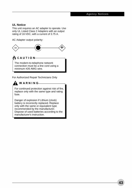
Agency Not ices
43
UL NoticeThis unit requires an AC adapter to operate. Useonly UL Listed Class 2 Adapters with an outputrating of 16 VDC, with a current of 3.75 A.
AC Adapter output polarity:
For Authorized Repair Technicians Only
+
The modem-to-telephone networkconnection must be a line cord using aminimum #26 AWG wire.
For continued protection against risk of fire,replace only with the same type and ratingfuse.
Danger of explosion if Lithium (clock)battery is incorrectly replaced. Replaceonly with the same or equivalent typerecommended by the manufacturer.Dispose of used batteries according to themanufacturer’s instruction.
Alb Active5 (39-44) 25/3/03, 12:26 PM43

44
Fuj i t su Sty l i s t i c ST4120/21 Table t PC User ’s Gu ide - Sec t ion One
Alb Active5 (39-44) 25/3/03, 12:03 PM44

45
AppendixWireless LAN User’s Guide
Alb Active6 (45-49) 25/3/03, 12:04 PM45

46
Fuj i t su Sty l i s t i c ST4120/21 Table t PC User ’s Gu ide - Sec t ion One
Alb Active6 (45-49) 25/3/03, 12:04 PM46
Wire less LAN User ’s Gu ide
47
FCC REGULATORY INFORMATION
Please note the following regulatory informationrelated to the optional wireless LAN device.
Regulatory Notes and StatementsWireless LAN, Health and Authorization for use
Radio frequency electromagnetic energy isemitted from Wireless LAN devices. Theenergy levels of these emissions, however, arefar much less than the electromagnetic energyemissions from wireless devices such asmobile phones. Wireless LAN devices are safefor use by consumers because they operatewithin the guidelines found in radio frequencysafety standards and recommendations. Theuse of Wireless LAN devices may be restrictedin some situations or environments, such as:
• On board an airplane, or
• In an explosive environment, or
• In situations where the interference risk toother devices or services is perceived oridentified as harmful.
In cases in which the policy regarding use ofWireless LAN devices in specific environmentsis not clear (e.g., airports, hospitals, chemicaloil/gas industrial plants, private buildings),obtain authorization to use these devices priorto operating the equipment.
Regulatory Information/DisclaimersInstallation and use of this Wireless LAN devicemust be in strict accordance with theinstructions included in the user documentationprovided with the product. Any changes ormodifications made to this device that are notexpressly approved by the manufacturer mayvoid the user’s authority to operate theequipment. The manufacturer is not responsiblefor any radio or television interference causedby unauthorized modification of this device, orthe substitution or attachment of connectingcables and equipment other than thosespecified by the manufacturer. It is theresponsibility of the user to correct anyinterference caused by such unauthorized
modification, substitution or attachment. Themanufacturer and its authorized resellers ordistributors will assume no liability for anydamage or violation of government regulationsarising from failure to comply with theseguidelines.
Federal Communications CommissionstatementThis device complies with Part 15 of FCCRules.
Operation is subject to the following twoconditions:(1) This device may not cause interference, and,(2) This device must accept any interference,including interference that may cause undesiredoperation of this device.
FCC Interference StatementThis equipment has been tested and found tocomply with the limits for a Class B digitaldevice, pursuant to Part 15 of the FCC Rules.These limits are designed to providereasonable protection against harmfulinterference in a residential installation. Thisequipment generates, uses, and can radiateradio frequency energy. If not installed andused in accordance with the instructions, itmay cause harmful interference to radiocommunications. However, there is noguarantee that interference will not occur in aparticular installation.
If this equipment does cause harmfulinterference to radio or television reception,which can be determined by turning theequipment off and on, the user is encouragedto try and correct the interference by one ormore of the following measures:
1. Reorient or relocate the receiving antenna.
2. Increase the distance between theequipment and the receiver.
3. Connect the equipment to an outlet on acircuit different from the one the receiver isconnected to.
4. Consult the dealer or an experienced radio/TV technician for help.
Alb Active6 (45-49) 25/3/03, 12:04 PM47
48
Fuj i t su Sty l i s t i c ST4120/21 Table t PC User ’s Gu ide - Sec t ion One
FCC Radio Frequency Exposure statement
This Wireless LAN radio device has beenevaluated under FCC Bulletin OET 65C andfound compliant with the requirements as setforth in CFR 47 Sections 2.1091, 2.1093, and15.247 (b) (4) addressing RF Exposure fromradio frequency devices. The radiated outputpower of this Wireless LAN device is far belowthe FCC radio frequency exposure limits.Nevertheless, this device shall be used in sucha manner that the potential for human contactduring normal operation is minimized. Whenusing this device, a certain separation distancebetween antenna and nearby persons must bemaintained to ensure RF exposure compliance.In order to comply with RF exposure limitsestablished in the ANSI C95.1 standards, thedistance between the antennas and the usershould not be less than 20 cm (8 inches).
Export restrictions
This product or software contains encryptioncode which may not be exported or transferredfrom the US or Canada without an approvedUS Department of Commerce export license.This device complies with Part 15 of FCCRules., as well as ICES 003 B / NMB 003 B.Operation is subject to the following twoconditions: (1) this device may not causeharmful interference, and (2) this device mustaccept any interference received, includinginterference that may cause undesirableoperation. Modifications not expresslyauthorized by Fujitsu PC Corporation mayinvalidate the user's right to operate thisequipment.
Alb Active6 (45-49) 25/3/03, 12:04 PM48
Wire less LAN User ’s Gu ide
49
BEFORE USING THIS DEVICEThank you for purchasing a Fujitsu ST4120/21Tablet PC with the Integrated Wireless LAN.This manual describes the basic operatingprocedures for the Wireless LAN (referred to asthe “device” in this manual) and how to set up awireless LAN network. Before using thisdevice, read this manual carefully to ensurecorrect operation of the device. Keep thismanual in a safe place for reference whileusing the device.
Characteristics of the DeviceThis device consists of a wireless LAN cardthat is attached to the computer via a mini-PCIslot.
The main characteristics are as follows:
• It uses the power saving communicationssystem in the 2.4 GHz band, and does notrequire any license for radio communication.
• It uses Direct Sequence Spread Spectrum(DS-SS), which is resistant to noise.
• This device complies with Wi-Fi, and is ableto communicate at the maximum transferrate of 11 Mbps.
• The maximum communication range isapproximately 120 feet (36.5 meters) insidea building. The range may be shorterdepending upon the installation factors, suchas walls and columns.
• Unauthorized access can be prevented withthe use of SSID and encryption key.
Wireless LAN Modes Using this DeviceAdHoc ModeThe “AdHoc Mode” refers to the networkconnecting two computers using wireless LANcards. This connection is called an “AdHocnetwork.”
Using an AdHoc network, you can obtain anetwork connection easily and at a low cost.
In the AdHoc mode, you can use the functionsupported by Microsoft Network, such as File
and Print Sharing to exchange files and sharea printer or other peripheral devices.
To use the AdHoc Mode, you must set thesame SSID and the same encryption key for allthe computers that are connected. Allconnected computers can communicate witheach other within the communication range.
Infrastructure ModeIf a number of computers are connectedsimultaneously in the AdHoc mode, thetransfer rate may be reduced, communicationsmay become unstable, or the networkconnection could fail. This is because allwireless LAN cards are using the same radiofrequency in the network.
To improve this situation, you can use awireless LAN access point, which is soldseparately. The wireless LAN network is in the“Infrastructure mode” when it uses an accesspoint, and such a connection is called the“Infrastructure Network.”
By using an access point, you can set and usea different communication channel for eachnetwork group. Each channel is given adifferent radio frequency, and it eliminates thecollision of communications and provides amore stable communications environment.Infrastructure mode is most suitable when youare configuring multiple wireless LANnetworks on the same floor.
To connect a wireless LAN network to a wiredLAN, you need an access point.
How to Handle This DeviceThe optional Integrated Wireless LAN device isalready installed in Fujitsu ST4120/21 TabletPC computers that have been so configured.Under normal circumstances, it should not benecessary for you to remove or reinstall it. TheLAN has been configured to support theoperating system with which your systemshipped.
The On/Off switch located on the Wireless LANcover turns the device on and off. You shouldswitch the device off when it is not in use inorder to maximize battery life.
Alb Active6 (45-49) 25/3/03, 12:04 PM49
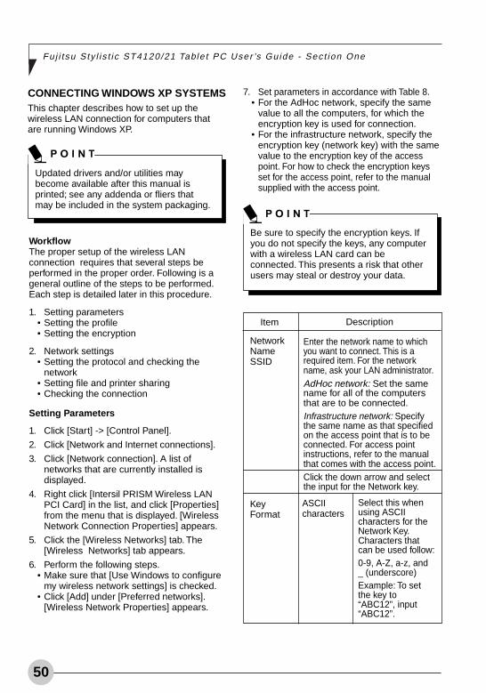
50
Fuj i t su Sty l i s t i c ST4120/21 Table t PC User ’s Gu ide - Sec t ion One
WorkflowThe proper setup of the wireless LANconnection requires that several steps beperformed in the proper order. Following is ageneral outline of the steps to be performed.Each step is detailed later in this procedure.
1. Setting parameters• Setting the profile• Setting the encryption
2. Network settings• Setting the protocol and checking the
network• Setting file and printer sharing• Checking the connection
Setting Parameters
1. Click [Start] -> [Control Panel].
2. Click [Network and Internet connections].
3. Click [Network connection]. A list ofnetworks that are currently installed isdisplayed.
4. Right click [Intersil PRISM Wireless LANPCI Card] in the list, and click [Properties]from the menu that is displayed. [WirelessNetwork Connection Properties] appears.
5. Click the [Wireless Networks] tab. The[Wireless Networks] tab appears.
6. Perform the following steps.• Make sure that [Use Windows to configure
my wireless network settings] is checked.• Click [Add] under [Preferred networks].
[Wireless Network Properties] appears.
Be sure to specify the encryption keys. Ifyou do not specify the keys, any computerwith a wireless LAN card can beconnected. This presents a risk that otherusers may steal or destroy your data.
CONNECTING WINDOWS XP SYSTEMSThis chapter describes how to set up thewireless LAN connection for computers thatare running Windows XP.
Updated drivers and/or utilities maybecome available after this manual isprinted; see any addenda or fliers thatmay be included in the system packaging.
7. Set parameters in accordance with Table 8.• For the AdHoc network, specify the same
value to all the computers, for which theencryption key is used for connection.
• For the infrastructure network, specify theencryption key (network key) with the samevalue to the encryption key of the accesspoint. For how to check the encryption keysset for the access point, refer to the manualsupplied with the access point.
Item
NetworkNameSSID
KeyFormat
Description
Enter the network name to whichyou want to connect. This is arequired item. For the networkname, ask your LAN administrator.AdHoc network: Set the samename for all of the computersthat are to be connected.Infrastructure network: Specifythe same name as that specifiedon the access point that is to beconnected. For access pointinstructions, refer to the manualthat comes with the access point.Click the down arrow and selectthe input for the Network key.
Select this whenusing ASCIIcharacters for theNetwork Key.Characters thatcan be used follow:0-9, A-Z, a-z, and_ (underscore)Example: To setthe key to“ABC12”, input“ABC12”.
ASCIIcharacters
Alb Active7 (50-60) 26/3/03, 3:04 PM50
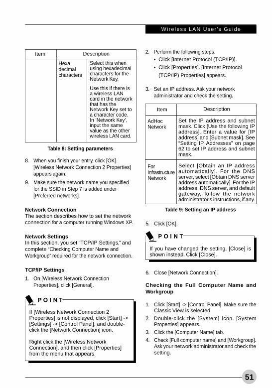
Wire less LAN User ’s Gu ide
51
8. When you finish your entry, click [OK].[Wireless Network Connection 2 Properties]appears again.
9. Make sure the network name you specifiedfor the SSID in Step 7 is added under[Preferred networks].
Network ConnectionThe section describes how to set the networkconnection for a computer running Windows XP.
Network SettingsIn this section, you set “TCP/IP Settings,” andcomplete “Checking Computer Name andWorkgroup” required for the network connection.
TCP/IP Settings
1. On [Wireless Network ConnectionProperties], click [General].
If [Wireless Network Connection 2Properties] is not displayed, click [Start] ->[Settings] -> [Control Panel], and double-click the [Network Connection] icon.
Right click the [Wireless NetworkConnection], and then click [Properties]from the menu that appears.
Item Description
Select this whenusing hexadecimalcharacters for theNetwork Key.
Use this if there isa wireless LANcard in the networkthat has theNetwork Key set toa character code.In ’Network Key’,input the samevalue as the otherwireless LAN card.
Hexadecimalcharacters
Table 8: Setting parameters
2. Perform the following steps.• Click [Internet Protocol (TCP/IP)].
• Click [Properties]. [Internet Protocol
(TCP/IP) Properties] appears.
3. Set an IP address. Ask your networkadministrator and check the setting.
Description
Set the IP address and subnetmask. Click [Use the following IPaddress]. Enter a value for [IPaddress] and [Subnet mask]. See“Setting IP Addresses” on page62 to set IP address and subnetmask.
Select [Obtain an IP addressautomatically]. For the DNSserver, select [Obtain DNS serveraddress automatically]. For the IPaddress, DNS server, and defaultgateway, follow the networkadministrator's instructions, if any.
AdHocNetwork
ForInfrastructureNetwork
Table 9: Setting an IP address
5. Click [OK].
6. Close [Network Connection].
Checking the Full Computer Name andWorkgroup
1. Click [Start] -> [Control Panel]. Make sure theClassic View is selected.
2. Double-click the [System] icon. [SystemProperties] appears.
3. Click the [Computer Name] tab.
4. Check [Full computer name] and [Workgroup].Ask your network administrator and check thesetting.
If you have changed the setting, [Close] isshown instead. Click [Close].
Item
Alb Active7 (50-60) 25/3/03, 12:04 PM51
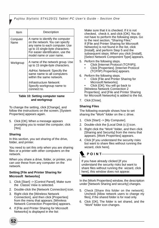
52
Fuj i t su Sty l i s t i c ST4120/21 Table t PC User ’s Gu ide - Sec t ion One
To change the setting, click [Change], andfollow the instructions on the screen. [SystemProperties] appears again.
5. Click [OK]. When a message appearsprompting you to restart the computer, click[Yes].
SharingIn this section, you set sharing of the drive,folder, and printer.
You need to set this only when you are sharingfiles or a printer with other computers on thenetwork.
When you share a drive, folder, or printer, youcan use these from any computer on thenetwork.
Setting [File and Printer Sharing forMicrosoft Networks]
1. Click [Start] -> [Control Panel]. Make surethe Classic View is selected.
2. Double-click the [Network Connection] icon.3. Right click the [Wireless Network
Connection], and then click [Properties]from the menu that appears. [WirelessNetwork Connection Properties] appears.
4. If [File and Printer Sharing for MicrosoftNetworks] is displayed in the list:
Make sure that it is checked. If it is notchecked, check it, and click [OK]. You donot have to perform the following steps. Goto the next section, “Sharing Files.”If [File and Printer Sharing for MicrosoftNetworks] is not found in the list, click[Install], and perform Step 5 and thesubsequent steps. When you click [Install],[Select Network Component Type] appears.
5. Perform the following steps.• Click [Internet Protocol (TCP/IP)].• Click [Properties]. [Internet Protocol
(TCP/IP) Properties] appears.6. Perform the following steps.
• Click [File and Printer Sharing forMicrosoft Networks].
• Click [OK]. You will go back to[Wireless Network Connection 2Properties], and [File and Printer Sharingfor Microsoft Networks] is added to the list.
7. Click [Close].
Sharing FilesThe following example shows how to setsharing the “Work” folder on the c: drive.
1. Click [Start] -> [My Computer].2. Double-click the [Local Disk (c:)] icon.3. Right click the “Work” folder, and then click
[Sharing and Security] from the menu thatappears. [Work Properties] appears.
4. Click [If you understand the security risksbut want to share files without running thewizard, click here].
In the [Work Properties] window, the descriptionunder [Network Sharing and security] changes.
5. Check [Share this folder on the network].Uncheck [Allow network users to change myfiles], if the shared folder is for read only.
6. Click [OK]. The folder is set shared, and the“Work” folder icon changes.
Description
A name to identify the computeron the network. You can specifyany name to each computer. Useup to 15 single-byte characters.For easier identification, use themodel name or user name.
A name of the network group. Useup to 15 single-byte characters.
AdHoc Network: Specify thesame name to all computerswithin the same network.
Infrastructure Network:Specify workgroup name toconnect to.
ComputerName
Workgroup
Table 10: Setting computer nameand workgroup
Item
If you have already clicked [If youunderstand the security risks but want toshare files without running the wizard, clickhere], this window does not appear.
Alb Active7 (50-60) 25/3/03, 12:04 PM52
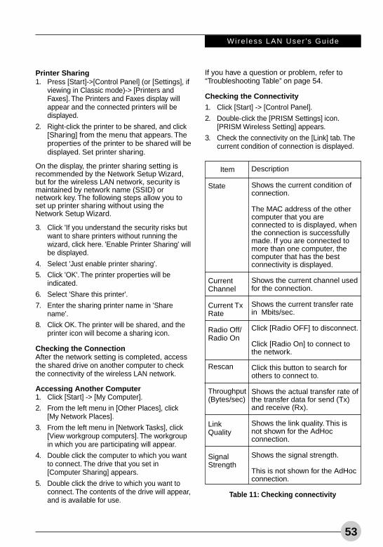
Wire less LAN User ’s Gu ide
53
Printer Sharing1. Press [Start]->[Control Panel] (or [Settings], if
viewing in Classic mode)-> [Printers andFaxes]. The Printers and Faxes display willappear and the connected printers will bedisplayed.
2. Right-click the printer to be shared, and click[Sharing] from the menu that appears. Theproperties of the printer to be shared will bedisplayed. Set printer sharing.
On the display, the printer sharing setting isrecommended by the Network Setup Wizard,but for the wireless LAN network, security ismaintained by network name (SSID) ornetwork key. The following steps allow you toset up printer sharing without using theNetwork Setup Wizard.
3. Click 'If you understand the security risks butwant to share printers without running thewizard, click here. 'Enable Printer Sharing' willbe displayed.
4. Select 'Just enable printer sharing'.
5. Click 'OK'. The printer properties will beindicated.
6. Select 'Share this printer'.
7. Enter the sharing printer name in 'Sharename'.
8. Click OK. The printer will be shared, and theprinter icon will become a sharing icon.
Checking the ConnectionAfter the network setting is completed, accessthe shared drive on another computer to checkthe connectivity of the wireless LAN network.
Accessing Another Computer1. Click [Start] -> [My Computer].
2. From the left menu in [Other Places], click[My Network Places].
3. From the left menu in [Network Tasks], click[View workgroup computers]. The workgroupin which you are participating will appear.
4. Double click the computer to which you wantto connect. The drive that you set in[Computer Sharing] appears.
5. Double click the drive to which you want toconnect. The contents of the drive will appear,and is available for use.
Description
Shows the current condition ofconnection.
The MAC address of the othercomputer that you areconnected to is displayed, whenthe connection is successfullymade. If you are connected tomore than one computer, thecomputer that has the bestconnectivity is displayed.
Shows the current channel usedfor the connection.
Shows the current transfer ratein Mbits/sec.
Click [Radio OFF] to disconnect.
Click [Radio On] to connect tothe network.
Click this button to search forothers to connect to.
Shows the actual transfer rate ofthe transfer data for send (Tx)and receive (Rx).
Shows the link quality. This isnot shown for the AdHocconnection.
Shows the signal strength.
This is not shown for the AdHocconnection.
Item
State
CurrentChannel
Current TxRate
Radio Off/Radio On
Rescan
Throughput(Bytes/sec)
LinkQuality
SignalStrength
Table 11: Checking connectivity
If you have a question or problem, refer to“Troubleshooting Table” on page 54.
Checking the Connectivity1. Click [Start] -> [Control Panel].
2. Double-click the [PRISM Settings] icon.[PRISM Wireless Setting] appears.
3. Check the connectivity on the [Link] tab. Thecurrent condition of connection is displayed.
Alb Active7 (50-60) 25/3/03, 12:04 PM53
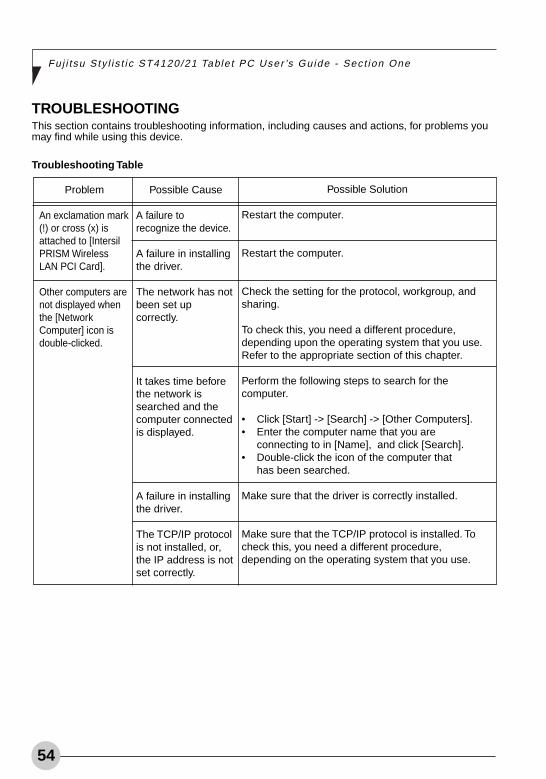
54
Fuj i t su Sty l i s t i c ST4120/21 Table t PC User ’s Gu ide - Sec t ion One
Problem
An exclamation mark(!) or cross (x) isattached to [IntersilPRISM WirelessLAN PCI Card].
Other computers arenot displayed whenthe [NetworkComputer] icon isdouble-clicked.
Possible Cause
A failure torecognize the device.
A failure in installingthe driver.
The network has notbeen set upcorrectly.
It takes time beforethe network issearched and thecomputer connectedis displayed.
A failure in installingthe driver.
The TCP/IP protocolis not installed, or,the IP address is notset correctly.
Possible Solution
Restart the computer.
Restart the computer.
Check the setting for the protocol, workgroup, andsharing.
To check this, you need a different procedure,depending upon the operating system that you use.Refer to the appropriate section of this chapter.
Perform the following steps to search for thecomputer.
• Click [Start] -> [Search] -> [Other Computers].• Enter the computer name that you are
connecting to in [Name], and click [Search].• Double-click the icon of the computer that
has been searched.
Make sure that the driver is correctly installed.
Make sure that the TCP/IP protocol is installed. Tocheck this, you need a different procedure,depending on the operating system that you use.
TROUBLESHOOTINGThis section contains troubleshooting information, including causes and actions, for problems youmay find while using this device.
Troubleshooting Table
Alb Active7 (50-60) 25/3/03, 12:04 PM54
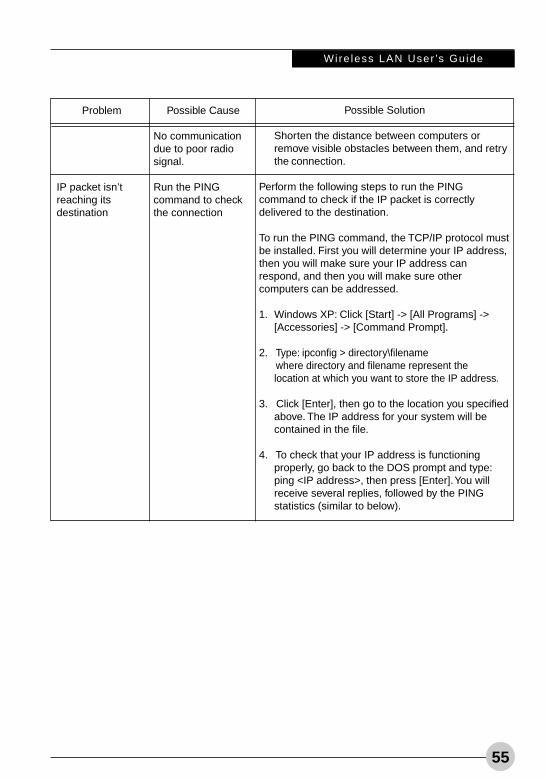
Wire less LAN User ’s Gu ide
55
Problem
IP packet isn’treaching itsdestination
Possible Cause
No communicationdue to poor radiosignal.
Run the PINGcommand to checkthe connection
Possible Solution
Shorten the distance between computers orremove visible obstacles between them, and retrythe connection.
Perform the following steps to run the PINGcommand to check if the IP packet is correctlydelivered to the destination.
To run the PING command, the TCP/IP protocol mustbe installed. First you will determine your IP address,then you will make sure your IP address canrespond, and then you will make sure othercomputers can be addressed.
1. Windows XP: Click [Start] -> [All Programs] ->[Accessories] -> [Command Prompt].
2. Type: ipconfig > directory\filename where directory and filename represent the
location at which you want to store the IP address.
3. Click [Enter], then go to the location you specifiedabove. The IP address for your system will becontained in the file.
4. To check that your IP address is functioningproperly, go back to the DOS prompt and type:ping <IP address>, then press [Enter]. You willreceive several replies, followed by the PINGstatistics (similar to below).
Alb Active7 (50-60) 25/3/03, 12:04 PM55
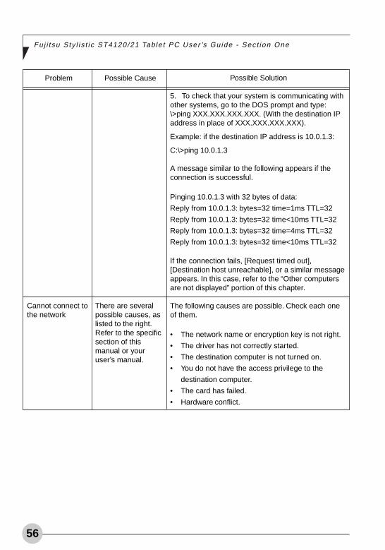
56
Fuj i t su Sty l i s t i c ST4120/21 Table t PC User ’s Gu ide - Sec t ion One
Problem
Cannot connect tothe network
Possible Cause
There are severalpossible causes, aslisted to the right.Refer to the specificsection of thismanual or youruser’s manual.
Possible Solution
5. To check that your system is communicating withother systems, go to the DOS prompt and type:\>ping XXX.XXX.XXX.XXX. (With the destination IPaddress in place of XXX.XXX.XXX.XXX).
Example: if the destination IP address is 10.0.1.3:
C:\>ping 10.0.1.3
A message similar to the following appears if theconnection is successful.
Pinging 10.0.1.3 with 32 bytes of data:
Reply from 10.0.1.3: bytes=32 time=1ms TTL=32
Reply from 10.0.1.3: bytes=32 time<10ms TTL=32
Reply from 10.0.1.3: bytes=32 time=4ms TTL=32
Reply from 10.0.1.3: bytes=32 time<10ms TTL=32
If the connection fails, [Request timed out],[Destination host unreachable], or a similar messageappears. In this case, refer to the “Other computersare not displayed” portion of this chapter.
The following causes are possible. Check each oneof them.
• The network name or encryption key is not right.
• The driver has not correctly started.
• The destination computer is not turned on.
• You do not have the access privilege to the
destination computer.
• The card has failed.
• Hardware conflict.
Alb Active7 (50-60) 25/3/03, 12:04 PM56
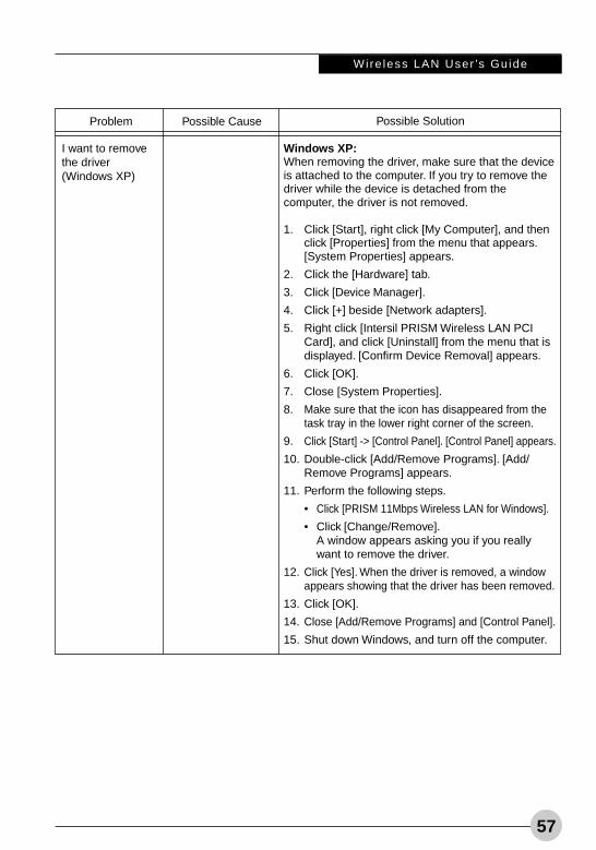
Wire less LAN User ’s Gu ide
57
Problem
I want to removethe driver(Windows XP)
Possible Cause Possible Solution
Windows XP:When removing the driver, make sure that the deviceis attached to the computer. If you try to remove thedriver while the device is detached from thecomputer, the driver is not removed.
1. Click [Start], right click [My Computer], and thenclick [Properties] from the menu that appears.[System Properties] appears.
2. Click the [Hardware] tab.
3. Click [Device Manager].
4. Click [+] beside [Network adapters].
5. Right click [Intersil PRISM Wireless LAN PCICard], and click [Uninstall] from the menu that isdisplayed. [Confirm Device Removal] appears.
6. Click [OK].
7. Close [System Properties].
8. Make sure that the icon has disappeared from thetask tray in the lower right corner of the screen.
9. Click [Start] -> [Control Panel]. [Control Panel] appears.
10. Double-click [Add/Remove Programs]. [Add/Remove Programs] appears.
11. Perform the following steps.
• Click [PRISM 11Mbps Wireless LAN for Windows].
• Click [Change/Remove].A window appears asking you if you reallywant to remove the driver.
12. Click [Yes]. When the driver is removed, a windowappears showing that the driver has been removed.
13. Click [OK].
14. Close [Add/Remove Programs] and [Control Panel].
15. Shut down Windows, and turn off the computer.
Alb Active7 (50-60) 25/3/03, 12:04 PM57
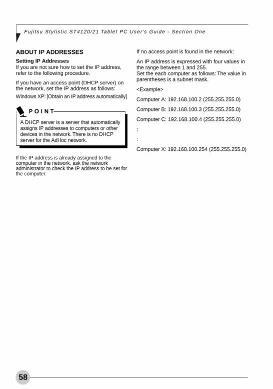
58
Fuj i t su Sty l i s t i c ST4120/21 Table t PC User ’s Gu ide - Sec t ion One
ABOUT IP ADDRESSESSetting IP AddressesIf you are not sure how to set the IP address,refer to the following procedure.
If you have an access point (DHCP server) onthe network, set the IP address as follows:
Windows XP: [Obtain an IP address automatically]
If the IP address is already assigned to thecomputer in the network, ask the networkadministrator to check the IP address to be set forthe computer.
A DHCP server is a server that automaticallyassigns IP addresses to computers or otherdevices in the network. There is no DHCPserver for the AdHoc network.
If no access point is found in the network:
An IP address is expressed with four values inthe range between 1 and 255.Set the each computer as follows: The value inparentheses is a subnet mask.
<Example>
Computer A: 192.168.100.2 (255.255.255.0)
Computer B: 192.168.100.3 (255.255.255.0)
Computer C: 192.168.100.4 (255.255.255.0)
:
:
Computer X: 192.168.100.254 (255.255.255.0)
Alb Active7 (50-60) 25/3/03, 12:04 PM58
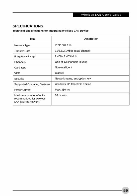
Wire less LAN User ’s Gu ide
59
Description
IEEE 802.11b
11/5.5/2/1Mbps (auto change)
2,400 - 2,483 MHz
One of 13 channels is used
Non-intelligent
Class B
Network name, encryption key
Windows XP Tablet PC Edition
Max: 350mA
10 or less
Item
Network Type
Transfer Rate
Frequency Range
Channels
Card Type
VCC
Security
Supported Operating Systems
Power Current
Maximum number of unitsrecommended for wirelessLAN (AdHoc network)
SPECIFICATIONSTechnical Specifications for Integrated Wireless LAN Device
Alb Active7 (50-60) 25/3/03, 12:04 PM59

60
Fuj i t su Sty l i s t i c ST4120/21 Table t PC User ’s Gu ide - Sec t ion One
Alb Active7 (50-60) 25/3/03, 12:04 PM60