Embed Size (px)
Citation preview

HP 300 MK2

3
INTRODUCTION
Congratulations and thank you for choosing the OCTAVE
HP 300 MK2 You are about to enjoy the benefits of one of the world's most innovative and reliable preamplifiers. Take care of it, and your preamplifier will provide you with many years of listening pleasure. You often hear people claim that there has been no real progress in tube amplifier design for years. The operating principles of tubes have been documented extensively and are well known to amplifier designers. The same can, of course, be said for transistor amplifiers. Nevertheless, there is still room for further development with both of these technologies. This is both necessary and desirable. With tube amplifiers in particular, a general reluctance to depart from the classic circuit designs has not done the technology any favours. Today's loudspeakers and source equipment provide better performance than ever before, but also make greater demands on amplifiers. Modern sound reproduction equipment delivers a level of performance at a price that simply would not have been possible 20 or even 10 years ago. These advances have been achieved through the application of cutting edge technology as it becomes available and affordable. Integrating these technologies into amplifier design demands a detailed knowledge of the inner workings of amplifiers and an appreciation of the sonic ramifications of each modification. We have specialized in tube amplification for the past 20 years, during which time we have developed a number of innovative technologies that have earned us a reputation as one of the leaders in the field. We hope you will enjoy many hours of wonderful music with your OCTAVE amplifier.
Andreas Hofmann

5
CONTENTS
Page
Introduction 1. OCTAVE technology ................................................................... 3 1.1. Differences to other tube amps ................................................... 3 1.2. Discription..................................................................................... 4 2. Safety instructions ........................................................................ 5 2.1. Before you begin .......................................................................... 5 2.2. Placement..................................................................................... 6 2.3. Warranty ....................................................................................... 6 3. Setting up ..................................................................................... 7 3.1. Connecting the amplifier............................................................... 7 3.2. Running in .................................................................................... 7 4. Operation: Front panel ................................................................ 8 5. Connections: Rear panel ............................................................. 10 6. Advanced function: The bypass mode ......................................... 11 6.1. The HP 300 MK2 in the bypass mode.......................................... 12 6.2. The HP 300 MK2 in the two channel mode.................................. 13 7. Advanced function: Connecting a processor................................ 14 8. Programmable remote control...................................................... 14 9. Tubes............................................................................................ 15 9.1. Tube layout .................................................................................. 15 9.2. Replacing tubes............................................................................ 16 9.3. Tube service life ........................................................................... 16 10. Option: Phono MM/MC................................................................. 17 10.1. The role of the phono preamplifier ............................................... 17 10.2. The phono section of the HP 300 MK2 ........................................ 17 10.3. Guidelines for connecting to the phono section ........................... 17 10.4. Adjusting the MC input ................................................................. 18 11. Troubleshooting............................................................................ 20 12. Technical data and dimensions.................................................... 21 13. Specification ................................................................................. 22

6
1. OCTAVE TECHNOLOGY 1.1. Differences to other tube amplifiers
1. The design goal of OCTAVE amplifiers is honest, natural soundreproduction. The sound characteristics of an amplifier are derived fromthe sum of all its parts. Tubes do not themselves guarantee high qualitysound.
2. The limitations of classic tube designs are evident as soon as you connectthe amplifiers. These designs often only perform to their full potential whenthey are used with special cables and amps. OCTAVE amplification andpower supply technology has largely overcome these well-knownproblems. Thanks to their unique output stage design, they will maintaintheir optimum sound quality with virtually any amplifier, irrespective of thecables.
3. OCTAVE employs the latest electronic circuit designs to create the bestpossible operating conditions for the tubes, and thus for the amplifier itself.
OCTAVE Tube Technology
Power-Management
Power supplyand
other functionsAmplifier +
Sound Quality
OCTAVE amplifiers are equipped with a proprietary control and monitoringsystem we call Power Management. This is an "electronic brain" within theamp that regulates and controls all of the amplifier's functions. It includesthe Soft Start Electronics that gently ramp up the heating and supplyvoltages to save wear and tear on the components. In the event of aproblem, the Power Management's protection system will disconnect theunit from the power supply. Power Management helps us to achieve acompletely consistent sound while at the same time ensuring the totalreliability of our products.
4. OCTAVE amplifiers are hand built and individually tested. They aredesigned and developed by Andreas Hofmann. The company has its ownwinding department, in which all transformers are specially custom woundfor each amplifier.
5. OCTAVE amplifiers are 100% built in Germany. Our employees are highlyqualified and committed. We collaborate closely with local specialistsubcontracting companies. The hardware components are allmanufactured on modern CNC machines.
Sound
Amplifier Design
Control + Monitoring
Hand built
made in Germany

7
1. OCTAVE TECHNOLOGY 1.2. Description HP 300 MK2 MKII The HP 300 MK2 MKII is a member of a new generation of tube preamplifiers built by
OCTAVE. The first model of this line was the reference preamplifier Jubilee. Heart of this line is a newly developed circuit design, which still has the tube as the central amplifying component, but the necessary output power is generated by a new type of super-gain semiconductor circuit.
As OCTACE decouples the output load from the tubes, the HP 300 MK2 convinces with excellent measuring results. Free from the output load the tubes can develop their tonal and dynamic sound characteristics unrestrained. It sounds vivid, relaxed, totally free or with one single word – simply light.
Because of that, the HP 300 MK2 preamplifier can be used extremely universal. Furthermore, the HP 300 MK2 is manufactured perfectly, which also finds expression in the
stable, low resonance solid-metal chassis. Resonances are thereby ruled out. The solid connecting sockets allow the connection of high-quality NF-wires with large plugs.
Every product of OCTAVE is built in Germany in single-piece production and is subject to a 100% check. A 48-hour endurance run completes the final inspection.
Over and above that the HP 300 MK2 uses a lavish special power supply, which was
developed especially for the HP 300 MK2. The power supply of the HP 300 MK2 carries out complex functions: On the one hand it
ensures a constant acoustic quality by preventing mains disturbances and by creating constant working conditions with electronic voltage stabilizations. On the other hand the built-in control logic guarantees highest reliability and achieves with soft-start-techniques the theoretically maximal possible lifetime of the tubes (up to approximately 10 Years or more).
An additional function of the power supply is the protection circuit, which releases the output of the HP 300 MK2 by a relay with a time delay or disconnects it immediately in case of a malfunction. Click-interferences etc. caused by the power supply are therefore absolutely ruled out.
Transformers are individually designed and produced in our own house. The bypass / multi channel facility makes the HP 300 MK2 to one of the most versatile
preamps in this range. This technology is possible throughout a logic controlled input section. The switching elements are high quality industrial grade gold contact relays.

8
2. SAFETY INSTRUCTIONS 2.1. Before you begin Before using your HP 300 MK2, please check your local line voltage and pay attention to this manual In case of emergency: disconnect the plug from the mains supply Never use an amplifier that is damaged or faulty. Make sure that it cannot be used until it has been repaired by a qualified service engineer. Make sure that there is easy access to the IEC socket and power cord. Do not open the case There are dangerously high voltages and hot tubes inside this equipment. To avoid a burn or the risk of electric shock, never allow anyone except qualified personnel to open the case or remove the grille. Servicing and maintenance For reasons of safety, please ensure that servicing, repairs and other modifications to OCTAVE equipment are carried out only by a qualified technician. Fuses should also only be changed by a qualified technician. Always replace fuses with ones of the same type and rating. If your amplifier requires servicing, please ship or take your equipment directly to OCTAVE or to one of our authorized service centres. Explanation of the warning symbols:
The exclamation point within an equilateral triangle is intended to alert the user to important operating and maintenance instructions. The lightning flash with arrowhead symbol within an equilateral triangle is intended to alert the user to the presence of uninsulated dangerous voltages' within the product's enclosure that may be sufficient to constitute a risk of electric shock to persons.
Before connecting Make sure that the voltage of your amplifier matches your electricity supply voltage. Grounding This amplifier is a protection class 2 device (without an earth conductor).

9
2. SAFETY INSTRUCTIONS 2.2. Placement 1. Location OCTAVE equipment is designed strictly for use in a dry domestic environment. Do not use it in the open air or in damp environments! Never place plants or liquid filled containers on your OCTAVE equipment. Take care that objects do not fall or liquids are not spilled into the enclosure. Should this happen, remove the mains plug immediately and have your amplifier checked by a qualified service technician. Condensation may form if the amplifier is taken from a cold environment into a warm one. If you do this, wait until the amplifier has reached room temperature and is dry before switching it on. Avoid installing the unit close to sources of heat such as radiators or anywhere that it may be in direct sunlight. Do not operate the unit near flammable materials, gases or vapours. Avoid areas where there may be heavy accumulations of dust or where the unit may be subject to mechanical vibration. Place your OCTAVE amplifier on a stable, even surface. 2. Cover Never operate the amplifier without the cover. 3. Ventilation Make sure that your amplifier has a good flow of air around it. If you intend to install your equipment in a cupboard or a shelf unit, ensure that there is at least a ten centimetre gap between the ventilation slots and the walls all around the amplifier. Do not rest the equipment on a soft surface such as carpet or foam sheeting. 2.3. Warranty OCTAVE can only guarantee the safety, reliability and performance of this unit if modifications and repairs are carried out by specialized personnel and if the amplifier is operated in accordance with the instructions contained in this manual.
10
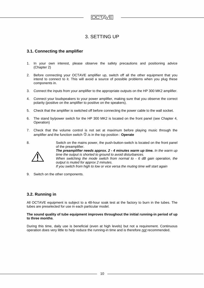
3. SETTING UP 3.1. Connecting the amplifier
1. In your own interest, please observe the safety precautions and positioning advice
(Chapter 2) 2. Before connecting your OCTAVE amplifier up, switch off all the other equipment that you
intend to connect to it. This will avoid a source of possible problems when you plug these components in.
3. Connect the inputs from your amplifier to the appropriate outputs on the HP 300 MK2 amplifier. 4. Connect your loudspeakers to your power amplifier, making sure that you observe the correct
polarity (positive on the amplifier to positive on the speakers). 5. Check that the amplifier is switched off before connecting the power cable to the wall socket. 6. The stand by/power switch for the HP 300 MK2 is located on the front panel (see Chapter 4,
Operation) 7. Check that the volume control is not set at maximum before playing music through the
amplifier and the function switch .is in the top position : Operate 8. Switch on the mains power, the push-button-switch is located on the front panel
of the preamplifier. The preamplifier needs approx. 2 - 4 minutes warm up time. In the warm up
time the output is shorted to ground to avoid disturbances. When switching the mode switch from normal to - 6 dB gain operation, the
output is muted for approx 2 minutes. If you switch from high to low or vice versa the muting time will start again 9. Switch on the other components. 3.2. Running in All OCTAVE equipment is subject to a 48-hour soak test at the factory to burn in the tubes. The tubes are preselected for use in each particular model. The sound quality of tube equipment improves throughout the initial running-in period of up to three months. During this time, daily use is beneficial (even at high levels) but not a requirement. Continuous operation does very little to help reduce the running-in time and is therefore not recommended.
11
4. OPERATION - Front panel
Tape
Gain -6 dB
Stand By
CD sym
CD
Aux
Tuner
Phono
Power
0 10
SourceOperate
BypassAux
Mute
HP 300 MK 2
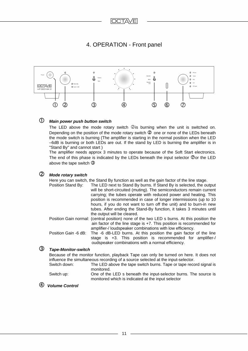
Main power push button switch
The LED above the mode rotary switch is burning when the unit is switched on. Depending on the position of the mode rotary switch one or none of the LEDs beneath the mode switch is burning (The amplifier is starting in the normal position when the LED –6dB is burning or both LEDs are out. If the stand by LED is burning the amplifier is in "Stand By" and cannot start )
The amplifier needs approx 3 minutes to operate because of the Soft Start electronics. The end of this phase is indicated by the LEDs beneath the input selector or the LED above the tape switch
Mode rotary switch
Here you can switch, the Stand By function as well as the gain factor of the line stage. Position Stand By: The LED next to Stand By burns. If Stand By is selected, the output
will be short-circuited (muting). The semiconductors remain current carrying; the tubes operate with reduced power and heating. This position is recommended in case of longer intermissions (up to 10 hours, if you do not want to turn off the unit) and to burn-in new tubes. After ending the Stand-By function, it takes 3 minutes until the output will be cleared.
Position Gain normal: (central position) none of the two LED s burns. At this position the ain factor of the line stage is +7. This position is recommended for amplifier-/ loudspeaker combinations with low efficiency.
Position Gain -6 dB: The -6 dB-LED burns. At this position the gain factor of the line stage is +3. This position is recommended for amplifier-/ oudspeaker combinations with a normal efficiency.
Tape-Monitor-switch Because of the monitor function, playback Tape can only be turned on here. It does not
influence the simultaneous recording of a source selected at the input-selector. Switch down: The LED above the tape switch burns. Tape or tape record signal is
monitored. Switch up: One of the LED s beneath the input-selector burns. The source is
monitored which is indicated at the input selector Volume Control
12
4. OPERATION - Front panel
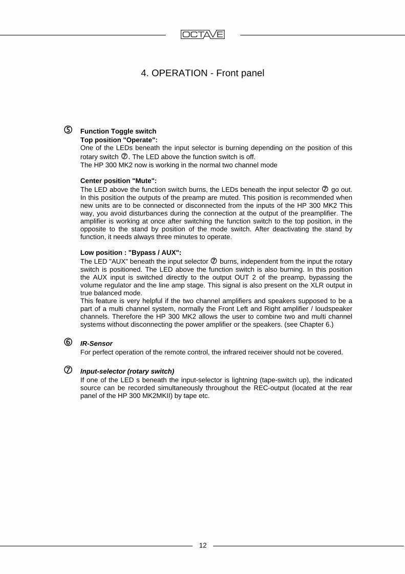
Function Toggle switch Top position "Operate": One of the LEDs beneath the input selector is burning depending on the position of this
rotary switch . The LED above the function switch is off. The HP 300 MK2 now is working in the normal two channel mode
Center position "Mute": The LED above the function switch burns, the LEDs beneath the input selector go out.
In this position the outputs of the preamp are muted. This position is recommended when new units are to be connected or disconnected from the inputs of the HP 300 MK2 This way, you avoid disturbances during the connection at the output of the preamplifier. The amplifier is working at once after switching the function switch to the top position, in the opposite to the stand by position of the mode switch. After deactivating the stand by function, it needs always three minutes to operate.
Low position : "Bypass / AUX":
The LED "AUX" beneath the input selector burns, independent from the input the rotary switch is positioned. The LED above the function switch is also burning. In this position the AUX input is switched directly to the output OUT 2 of the preamp, bypassing the volume regulator and the line amp stage. This signal is also present on the XLR output in true balanced mode.
This feature is very helpful if the two channel amplifiers and speakers supposed to be a part of a multi channel system, normally the Front Left and Right amplifier / loudspeaker channels. Therefore the HP 300 MK2 allows the user to combine two and multi channel systems without disconnecting the power amplifier or the speakers. (see Chapter 6.)
IR-Sensor
For perfect operation of the remote control, the infrared receiver should not be covered. Input-selector (rotary switch) If one of the LED s beneath the input-selector is lightning (tape-switch up), the indicated
source can be recorded simultaneously throughout the REC-output (located at the rear panel of the HP 300 MK2MKII) by tape etc.

13
5. CONNECTIONS: Rear panel
TU AUX CD TAPE OUTPUTS
REC PLAY
L
R
R LGND
CDSYM
PH
HP 300 MK2 Balanced Tube Preamp
Professional SeriesOUT 1 OUT 2
AC 230 V50/60 Hz
40 W
MULTICHANNEL
CD SYM XLR-input for balanced sources like CD-player etc. PH-input
Model HP 300 MK2 line: This is a normal line-input for high level-units Model HP 300 MK2 phono: This is the phono MC-input (see "Setting the MC-input") GND (Ground)-connector Suggested connection to the corresponding ground wire from your turntable. (See
”Connection reference phono MC”) Tuner
Single ended input AUX
Line input for Video, TV or alternatively, as a second function, the input for the front channels of the multi channel system.
CD Single ended input
Tape rec. Recording output for tape, cassette- or dat-recorders Tape play Connect these Inputs to the play-Outputs of your recorder. Outputs
Two single ended and one balanced output. In the Bypass/ Aux mode the signal is switched to the OUT 2 and the balanced output. The single ended OUT 1 is furthermore connected to the volume regulated line stage of the HP 300 MK2 amplifying the AUX signal. This output can be used for additional earphone amps or similar.
Model identification plate Model and serial number. AC-mains receptacle IEC-Standard AC-mains receptacle Comment: In the connection area, the lower socket line (red) is for the right channel, the upper
socket line (white) is for the left channel. Pin configuration XLR-sockets: : 1 = ground, 2 = plus, 3 = minus
14
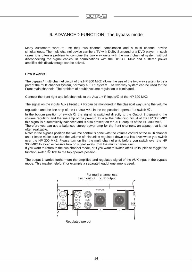
6. ADVANCED FUNCTION: The bypass mode Many customers want to use their two channel combination and a multi channel device simultaneous. The multi channel device can be a TV with Dolby Surround or a DVD player. In such cases it is often a problem to combine the two way units with the multi channel system without disconnecting the signal cables. In combinations with the HP 300 MK2 and a stereo power amplifier this disadvantage can be solved. How it works The bypass / multi channel circuit of the HP 300 MK2 allows the use of the two way system to be a part of the multi channel system, normally a 5 + 1 system. The two way system can be used for the Front main channels. The problem of double volume regulation is eliminated. Connect the front right and left channels to the Aux L + R inputs of the HP 300 MK2 The signal on the inputs Aux ( Front L + R) can be monitored in the classical way using the volume
regulation and the line amp of the HP 300 MK2 in the top position "operate" of switch . In the bottom position of switch the signal is switched directly to the Output 2 bypassing the volume regulator and the line amp of the preamp. Due to the balancing circuit of the HP 300 MK2 this signal is automatically balanced and is also present on the XLR outputs of the HP 300 MK2. Therefore you can use a balanced stereo power amp for the front channels, an aspect that is not often realizable. Note: In the bypass position the volume control is done with the volume control of the multi channel unit. Please make sure that the volume of this unit is regulated down to a low level when you switch over the HP 300 MK2. Please turn on first the multi channel unit, before you switch over the HP 300 MK2 to avoid excessive turn on signal levels from the multi channel unit. If you want to return to the two channel mode, or if you want to switch off all units, please toggle the function switch first to the top operate position. The output 1 carries furthermore the amplified and regulated signal of the AUX input in the bypass mode. This maybe helpful if for example a separate headphone amp is used. For multi channel use: cinch output XLR output
PE OUTPUTS
PLAY
L
R
R L
OUT 2OUT 1
Regulated pre out

15
6. ADVANCED FUNCTION: The bypass mode 6.1. The HP 300 MK2 in the bypass mode
Multi channel unitDVD-Player etc.
Front L Front R
HP 300MK2
AUX L AUX R
Cinch / XLR-Input L
Cinch / XLR-Input R
Power amplifier
Front - Main Loudspeakers
Rear L Center Rear R
Two channel unitCD /SACD, Tuner,
Tape etc.
OUT 2 / XLR OUT 2 / XLR
L R
OUT 1OUT 1
In the multi channel mode the common volume of the multi channel system has to be adjusted at the multi channel source, eg the DVD player, TV, etc. In the bypass mode the volume control of the HP 300 MK2 is out of function except the output 1. Special features: 1) The tape record monitor function is also available in bypass mode. Tape monitoring is given
on out 1. Tape switch in position "tape" 2) The AUX multi channel signal is present as well on out 1 regulated and amplified. Tape
switch in position "source"

16
6. ADVANCED FUNCTION: The bypass mode 6.2. The HP 300 MK2 in the two channel mode
Front L Front R
HP 300MK2
CD / TU etc. L
CD / TU etc. R
Cinch / XLR-Input L
Cinch / XLR-Input R Rear L Center Rear R
OUT 1 + 2 + XLR OUT 1 + 2 + XLR
L R
Two channel unitCD /SACD, Tuner,
Tape etc.
Multi channel unitDVD-Player etc.
Power amplifier
Front - Main Loudspeakers In the two channel mode all three outputs are regulated and amplified. In the two channel mode the AUX input can be used as a normal line high level input

17
7. ADVANCED FUNCTION: Connecting a processor
The tape loop offers the possibility to connect a digital or analog sound processor into the signal path of the HP 300 MK2. This can be a room processor or similar. Modern processors include either digital and analog inputs. The tape loop gives the user the possibility to use both of this technologies. How to do : The processor should be connected in the analog way with his analog input to the TAPE record outputs of the HP 300 MK2. The analog outputs of the processor have to be connected to the TAPE-Play inputs of the HP 300 MK2. In this way the processor is receiving the selected signal of the HP 300 MK2 input. In this way the corrected signal of the processor is usable in the TAPE position of the Tape-Switch Any digital source like CD can connected direct to the processor. Most of the processors are equipped with analog and digital inputs. This technology allows the use of a digital processor both in the digital and in the analog path without degradation of the analog signal. Switching between the two ways is very comfortable via the Tape switch . Of course this possibility is only realizable if there is no tape in use.
8. PROGRAMMABLE REMOTE CONTROL
Select your OCTAVE amplifier on the touch screen panel with button AUX. Once selected you can always control the volume directly by pushing the button Vol + or Vol - . Detailed information relating the use of the remote control you find in the owner's manual of the HOME THEATRE MASTER REMOTE
Device selector OCTAVE code B Volume up
Volume down

18
9. TUBES
9.1. Tube layout
power supply
boardline-
boardphono MC-
board
Before opening the cover it is mandatory to remove the power cord from the mains power inlet.
tubes used also available under this discription Line board
ECC 82 (E 82 CC / ECC 802 S / 12 AU 7 / 5814 A) ECC 88 (6 DJ 8 / E 88 CC / 6922)
Phono MC board
ECC 81 (E 81 CC / ECC 801 S / 12 AT 7 / 12 AT 7 WA)

19
9. Tubes 9.2. Replacing tubes Please use only original OCTAVE replacement tubes. These have been selected and tested for use in our amplifiers. Important! Changing tubes is a job for a qualified technician! 1. Switch off the preamplifier, unplug the power cord from the wall socket, and allow the unit
10 minutes to cool down.
2. Take off the cover by removing the M 3 screws, (10 pc.) 3. Take out the old tubes. Carefully remove the tubes from their sockets, taking care not to exert sideward pressure
on the sockets. 4. Fit new tubes Please ensure that the tube pins are all perfectly straight before inserting your new tubes.
Straighten any bent pins very carefully by hand if necessary. 5. Cleaning tips Cleaning agents and contact cleaners are not recommended for tube sockets. Clean dirty
sockets with compressed air and carefully clean tarnished tube pins using a wire brush. 6. Please note: No adjustments are necessary to your amplifier after fitting new tubes. It may take new tubes some time (up to 300 hours) to achieve their optimum sound
quality. Manufacturing faults in tubes may only become evident after about 100 hours of use. You
should therefore be wary of installing untested tubes. However, faulty tubes or tubes of the incorrect type will normally not damage the amplifier.
9.3. Tube service life Thanks to the protection circuits and soft start electronics, the tubes used in your amplifier
should achieve an average service life of 5 - 10 years. Because the tubes have different service lives, it should never be necessary to renew the
entire tube complement at the same time.

20
10. PHONO MC OPTION 10.1. The role of the phono preamplifier A record player is an electro-mechanical device. Music signals are "pressed" into the grooves in the record, and these are physically tracked and read by the pickup cartridge. In order to get the entire 20 Hz - 20 KHz frequency range into the grooves, the frequency response has to be shaped by lowering the level of the low frequency information and raising the level of the high frequency information. This predefined equalization curve is known as RIAA equalization. A phono amplifier must exactly equalize for RIAA recording characteristic if it is to avoid colouring the sound. Equalization accuracy must be within 0.5 dB over the entire frequency range, with channel matching of at least 0.1 dB. 10.2. The phono section of the HP 300 MK2 MKII The phono section of the HP 300 MK2MKII is an enhanced version of our hybrid phono technology. The phono section now offers a greater level of compatibility with low output and low impedance moving coil cartridges. Most preamps have problems with such cartridges, since both gain and input impedance issues have to be addressed simultaneously. We have developed an MC head amp that successfully eliminates the problem areas. At the heart of the equalizer is a tube circuit containing 1 tube and two integrated circuits. It incorporates a switchable subsonic filter, which prevents very low frequencies generated by warped records or tone arm resonances from overloading the loudspeakers. (A) 10.3. Guidelines for connecting to the phono section 1. Plug the RCA phono cable from your turntable into the appropriate (phono MC ) input
on your HP 300 MK2. Turn the input selector to phono. 2. Connect the earth cable supplied with your turntable to the GND connection on the
HP 300 MK2 , following the instructions provided by the turntable/arm manufacturer. Some tonearms do not have a separate earth cable, as the pickup system is earthed via the RCA phono plugs.
Explanation: The earth is generally connected to the tonearm or the headshell. This is necessary to prevent hum or radio interference. It is usually advisable to connect the earth cable to reduce this kind of interference.

21
directionfront panel
offon
1 slide switch
10. PHONO MC OPTION 10.4. Adjusting the MC input
Before you can adjust the MC input, you need to take off the cover by removing the M 3 screws, (12 pc.) Before opening the cover it is mandatory to remove the power cord from the mains power inlet.
Gain - Settingfor both channels
Switch for Subsonicfilterleft and right channel
Load - Impedance
(A)
(B)
(C)
(A) Subsonicfilter
Rippled records can create subsonic disturbances. The subsonicfilter eliminates this disturbances. Cutoff frequency is 15 Hz
Attentuation is 12 dB/oct. State of delivery: Subsonicfilter on
(B) Gain- Setting
The gain switch allows you to match the gain factor of the phono-amp for your cartridge. gain high: for normal MC-cartridges < 0,5 mV gain low: for high Output-MC-Systems > 0,5 mV State of delivery: gain high
slide switch
gainlow
gainhigh
1

22
10. PHONO MC OPTION 10.4. Adjusting the MC input (C) Setting the MC-Load-Impedance
onoff
8 Sliding switches
directionfront panel
Adjustment range
Left channel
Switch 1 – 4 Right channel Switch 5 - 8
Switch option
Switch no.
Switch position
Resistance(ohms)
Switchno.
Switchposition
Resistance (ohms)
1 all off 1000 All off 1000 2 1 on 500 5 on 500 3 2 on 250 6 on 250 4 1 + 2 on 200 5 + 6 on 200 5 3 on 100 7 on 100 6 1 + 3 on 90 5 + 7 on 90 7 2 + 3 on 76 6 + 7 on 76 8 4 on 75 8 on 75 9 1 + 2 + 3 on 71 5 + 6 + 7 on 71
10 1 + 4 on 69 5 + 8 on 69 11 2 + 4 on 61 6 + 8 on 61 12 1 + 2 + 4 on 57 5 + 6 + 8 on 57 13 3 + 4 on 44 7 + 8 on 44 14 1 + 3 + 4 on 42 5 + 7 + 8 on 42 15 2 + 3 + 4 on 39 6 + 7 + 8 on 39 16 all on 37 all on 37
The input impedance setting is important in achieving a balanced sound from your pickup. You will find the recommended impedance in the specifications supplied with your pickup. Default factory setting: 100 ohms - optimum for the most low output MC systems
23
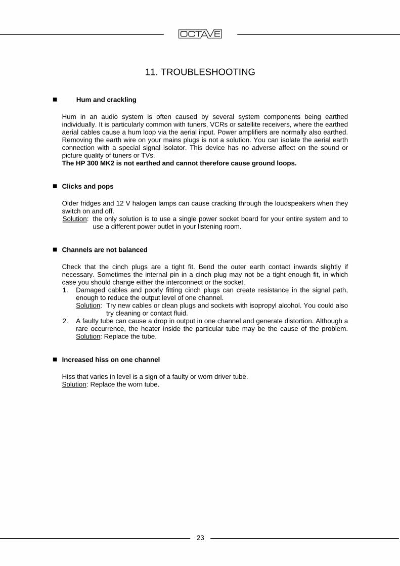
11. TROUBLESHOOTING Hum and crackling Hum in an audio system is often caused by several system components being earthed
individually. It is particularly common with tuners, VCRs or satellite receivers, where the earthed aerial cables cause a hum loop via the aerial input. Power amplifiers are normally also earthed. Removing the earth wire on your mains plugs is not a solution. You can isolate the aerial earth connection with a special signal isolator. This device has no adverse affect on the sound or picture quality of tuners or TVs.
The HP 300 MK2 is not earthed and cannot therefore cause ground loops. Clicks and pops
Older fridges and 12 V halogen lamps can cause cracking through the loudspeakers when they switch on and off. Solution: the only solution is to use a single power socket board for your entire system and to
use a different power outlet in your listening room. Channels are not balanced Check that the cinch plugs are a tight fit. Bend the outer earth contact inwards slightly if
necessary. Sometimes the internal pin in a cinch plug may not be a tight enough fit, in which case you should change either the interconnect or the socket. 1. Damaged cables and poorly fitting cinch plugs can create resistance in the signal path,
enough to reduce the output level of one channel. Solution: Try new cables or clean plugs and sockets with isopropyl alcohol. You could also
try cleaning or contact fluid. 2. A faulty tube can cause a drop in output in one channel and generate distortion. Although a
rare occurrence, the heater inside the particular tube may be the cause of the problem. Solution: Replace the tube.
Increased hiss on one channel Hiss that varies in level is a sign of a faulty or worn driver tube.
Solution: Replace the worn tube.
24
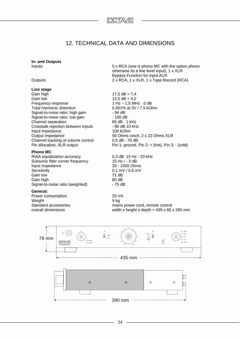
12. TECHNICAL DATA AND DIMENSIONS
In- and Outputs Inputs 5 x RCA (one is phono MC with the option phono otherwise its a line level input), 1 x XLR Bypass-Function for input AUX Outputs 2 x RCA, 1 x XLR, 1 x Tape Record (RCA) Line stage Gain high 17,5 dB = 7,4 Gain low 12,5 dB = 4,2 Frequency response 1 Hz – 1,5 MHz -3 dB Total harmonic distortion 0.001% at 3V / 7.5 kOhm Signal-to-noise ratio: high gain - 94 dB Signal-to-noise ratio: low gain - 100 dB Channel separation 65 dB 1 kHz Crosstalk rejection between inputs - 86 dB 10 kHz Input impedance 100 kOhm Output impedance 56 Ohms cinch; 2 x 22 Ohms XLR Channel tracking of volume control 0.5 dB - 70 dB Pin allocation, XLR output Pin 1: ground, Pin 2: + (hot), Pin 3: - (cold)
Phono MC RIAA equalization accuracy 0,3 dB 15 Hz - 20 kHz Subsonic filter corner frequency 15 Hz / - 3 dB Input impedance 30 - 1000 Ohms Sensitivity 0.1 mV / 0,5 mV Gain low 71 dB Gain high 80 dB Signal-to-noise ratio (weighted) - 75 dB
General: Power consumption 25 VA Weight 9 kg Standard accessories mains power cord, remote control overall dimensions width x height x depth = 435 x 65 x 390 mm
78 mm
435 mm
Tape
Gain -6 dB
Stand By
CD sym
CD
Aux
Tuner
Phono
Power
0 10
Source
Operate
BypassAux
Mute
390 mm

25
13. SPECIFICATION Features The HP 300 MK2MKII is fitted as standard with two cinch outputs, one XLR output and
one XLR input. Gain of the line amplifier and the phono board also is switchable to adjust the overall
gain of the preamplifier - amplifier combination An optional phono MC module may be added any time. MC input impedance is adjustable over a wide range. Soft-start for heaters, operating voltage and signal output. This results in maximum
service life of the tubes and noise-free switch-on/off. The output is enabled after 4 minutes.
Diagrams
Overall distortion (THD + noise) of line stage from 20 Hz - 200 kHz. Distortion remains low up to 20 kHz
Frequency response accuracy of line stages in 'low gain'setting. 20 Hz - 200 kHz: 0.1 dB
26
13. SPECIFICATION
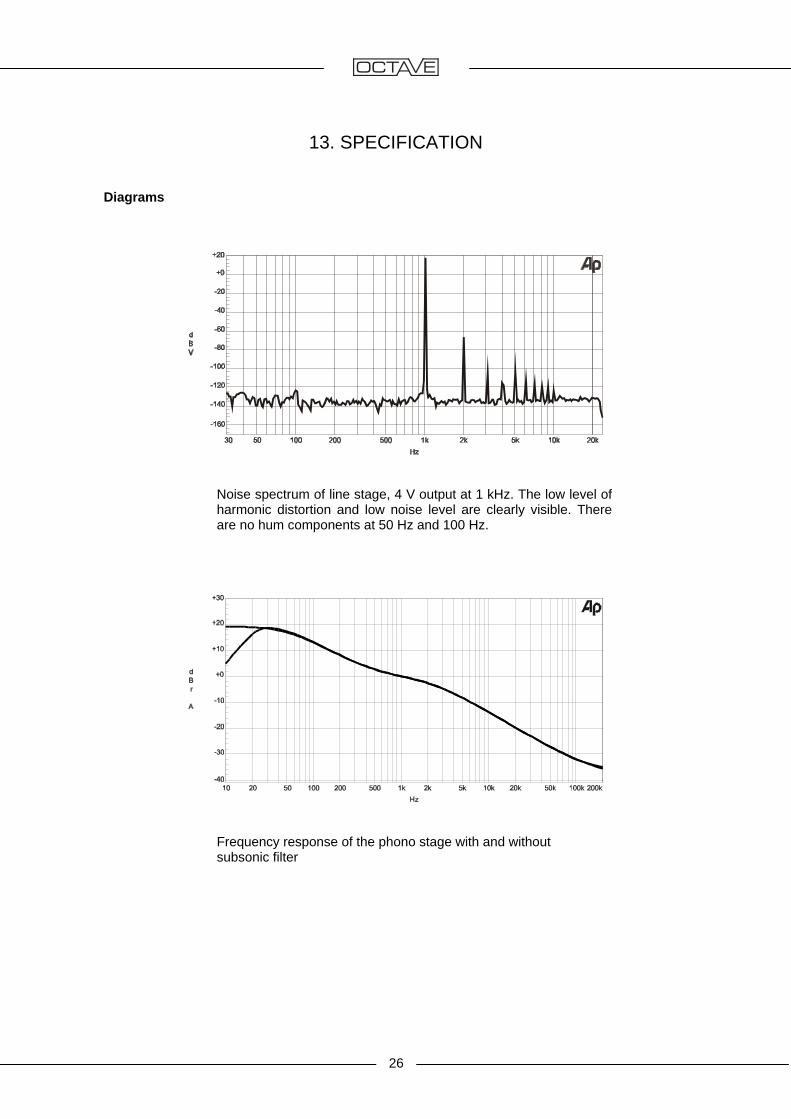
Diagrams
Noise spectrum of line stage, 4 V output at 1 kHz. The low level of harmonic distortion and low noise level are clearly visible. There are no hum components at 50 Hz and 100 Hz.
Frequency response of the phono stage with and without subsonic filter

OCTAVE AUDIO Germany
www.octave.de
We reserve the right to alter and improve thespecifications in pursuit of better. OCTAVElogo is a registered trade mark of AndreasHofmann. Copyright by Andreas Hofmann.Reproduction in whole or part is prohibited.edited EN2010