Embed Size (px)
Citation preview
DEGREE PROJECT IN THE BUILT ENVIRONMENTSTOCKHOLM, SWEDEN 2018
KTH ROYAL INSTITUTE OF TECHNOLOGYSCHOOL OF ARCHITECTURE AND THE BUILT ENVIRONMENTwww.kth.se
TRITA-ABE-MBT-186
Decision-making model for track system of high-speed rail linesBallasted track, ballastless track or both?
VERONIKA SÁRIK
VERONIKA SÁRIK D
ecision-making m
odel for track system of high-speed rail lines
KTH
2018

TRITA-ABE-MBT-186
Decision-making model for track system of high-speed rail lines
Ballasted track, ballastless track or both?
Veronika Sárik
Master’s thesis
March 2018
School of Architecture and Built Environment
KTH Railway Group
KTH Royal Institute of Technology
Stockholm, Sweden

Decision-making model for track system of high-speed rail lines Veronika Sárik
2
Decision-making model for track system of high-speed rail lines Veronika Sárik
3
Abstract
During the 50 years of existence of high speed railways, the track structure solutions have developed
both in number and in type. As of today, in case of conventional railway, there are 2 main types one
could mention: ballasted and ballastless track solutions. However, there is no standardized procedure
for choosing between these systems and between their respective variants, the decision is made on a
case-by-case basis.
This thesis aims to create a generic framework for decision making, primarily taking into account
technical details. The model, the input parameters and variables can be easily adjusted and customized
based on national standards, practices or other considerations, but the primary focus in the thesis have
been the current Swedish regulations.
The thesis has an overview on the influencing factors and attempts to include the most crucial ones of
these into a decision-making model. This model compares 3 alternatives, namely the ballastless
alternative, the ballasted alternative and the alternating system option, in which case the track system
selection happens based on local factors, such as geotechnical conditions. These are considered and
evaluated through Fuzzy logic, which supports the system selection affected by various sources of
uncertainty. The decision is finally made through an LCC calculation. In order to handle the great
uncertainties in the data used in the LCC, a Monte Carlo simulation is performed.
The main added value of the thesis is considered to be the methodology for choosing the systems based
on life-cycle cost after careful technical evaluation. This approach might provide basis for decision for
track systems of high speed rail lines.
I hope you find it an interesting read,
Veronika Sárik
Decision-making model for track system of high-speed rail lines Veronika Sárik
4
Sammanfattning
Under de 50 år som höghastighetsjärnvägar har existerat, har olika konstruktionslösningar för banorna
utvecklats både i antal och av olika slag. Idag, om man tänker på konventionell järnväg, finns det två
olika huvudtyper: ballasterat (makadam) och ballastfria spårlösningar. Det finns emellertid ingen
standardiserad metod för att välja mellan dessa två olika system och deras respektive varianter och
beslutet fattas från fall till fall.
Det här examensarbetet syftar till att skapa en generell ram för beslutsfattande, främst med hänsyn till
tekniska detaljer. Modellen, ingångsparametrarna och variablerna kan enkelt justeras och anpassas
baserat på olika nationella standarder, tillämpningar eller andra överväganden, men examensarbetet
utgår från det svenska regelverket.
Examensarbetet har en översikt över beslutsfaktorerna och försöker inkludera de mest avgörande av
dem till den beslutsfattande modellen. Denna modell jämför tre olika alternativ, nämligen ballasterat
spår, ballastfria spår och ett kombinationsalternativ. Kombinationen är beroende av lokala faktorer,
t.ex. geotekniska förhållanden. Dessa analyseras och utvärderas genom ”Fuzzy logik”, som stöder det
systemval som påverkas av olika källor av osäkerhet. Beslutet fattas slutligen genom en LCC
(livscykelkostnads) beräkning. För att hantera de stora osäkerheterna i de data som används i LCC,
utförs även en Monte Carlo simulering.
Huvudmålet med detta examensarbete är att utveckla metodiken för att välja system. Detta, baserat på
en livscykelkostnadsberäkning efter en noggrann teknisk utvärdering. Denna metod kan därmed utgöra
grund inför beslut vid val av spårsystem till höghastighetsjärnvägar.
Összefoglalás
A nagysebességű vasutak 50 éves története során a felépítményi szerkezetek mind számosságukban,
mind típusukban komoly változáson estek keresztül. A hagyományos vasúti rendszerek tekintetében 2
fő típust különböztetünk meg, a hagyományos zúzottkő ágyazatos és a beton elemes felépítményt.
Azonban szabványosított döntéshozatal a mai napig nem áll rendelkezésre, a döntés a rendszerek között
eseti alapon történik.
Ez a diplomamunka egy olyan döntéshozó rendszert kíván bemutatni, mely általánosan használható és
személyre/országra/infrastruktúrafenntartóra szabható, azonban a dolgozat során elsősorban a svéd
szabályok és rendelkezések kerültek előtérbe. Kiemelendő, hogy kizárólag technikai szempontok
kerültek figyelembe vételre.
A dolgozat áttekinti a döntést befolyásoló tényezőket, melyek közül a legfontosabbak a modellben is
szerepelnek. 3 alternatíva kerül összehasonlításra, a zúzottkő ágyazatos, a beton elemes és a váltakozó
rendszer, melyben a geotechnikai körülményektől függően akár zúzottköves, akár betonelemes
felépítmény megvalósítható. A geotechnikai körülmények Fuzzy logikával kerülnek kiértékelésre, amely
a döntéshozatal során megjelelő bizonytalanságok kezelését hivatott szolgálni. A döntéshozatalt LCC,
életciklus költség kalkuláción keresztül végzi el a modell. A bizonytalanságok kezelésére Monte Carlo
analízis szolgál.
Az elsődleges hozzáadott értekként a módszertan emelhető ki, mely a körültekintő elemzésen és
életciklus költség számításon keresztük hoz döntést. Ez a megközelítés alapul szolgálhat a nagysebességű
vasutak felépítményi rendszerének választásakor.

Decision-making model for track system of high-speed rail lines Veronika Sárik
5
Acknowledgements
I have 4 men to be especially thankful for, for being able to do this Master’s thesis.
First, to Anders Lindahl, my supervisor and teacher from KTH, who had me nagging him with railway
research from day 1 and who from that day helped me get all the opportunities inside and outside of
campus to learn, develop and thrive. I hope you will never stop helping and encouraging your students,
as you have never stopped helping and encouraging me.
I’d like to take the opportunity to thank Michael Than, my industrial supervisor, who helped me with
uncountable advices and guidance regarding the thesis and the railway industry in general. Without his
knowledge and contacts in his incredibly wide network, this work could not exist this way. I hope you
will continue to work with students, all deserves a caring supervisor like you.
I’d like express my gratitude to Jan Dahlberg, my boss at Sweco, who took a chance on me 2 years ago,
when I applied to work at the company. I hope I lived up to your expectations and will do my best to
continue to do that.
At last, but not at least, I would like to thank my boyfriend, Károly Szipka, for supporting, inspiring and
helping me throughout not only this thesis, but my entire Master’s and my journey here in Sweden. I
simply couldn’t have done this without you.
Moreover, I would like to thank all interviewees for their time and contribution, all of my colleagues at
Sweco who supported me during my studies and all my friends and family for always being there for me.

Decision-making model for track system of high-speed rail lines Veronika Sárik
6
Decision-making model for track system of high-speed rail lines Veronika Sárik
7
Table of contents
1. Introduction ........................................................................................................................................... 9
Background ................................................................................................................................................ 9
Purpose ....................................................................................................................................................... 9
Aim of the study ......................................................................................................................................... 9
Methodology ............................................................................................................................................ 10
Requirements, conditions and limitations ............................................................................................. 10
2. Track systems on HSR lines ................................................................................................................. 11
2.1. Ballasted track .............................................................................................................................. 11
2.2. Ballastless track ........................................................................................................................... 16
3. State-of-art ........................................................................................................................................... 21
3.1. Decision driving factors .............................................................................................................. 21
3.2. Decision making – literature review .......................................................................................... 41
3.3. Fuzzy logic – literature review .................................................................................................... 42
3.4. Decision-making for track systems of high-speed rail lines in international literature .......... 44
3.5. LCC literature review .................................................................................................................. 46
4. Decision making model ....................................................................................................................... 53
4.1. Model variables ........................................................................................................................... 53
4.2. Input data .................................................................................................................................... 54
4.3. Presentation of the alternatives .................................................................................................. 55
4.4. Presentation of decision making model ..................................................................................... 56
4.5. Global factors ............................................................................................................................... 58
4.6. Local factors ................................................................................................................................. 59
4.7. Section selection .......................................................................................................................... 64
4.8. LCC ............................................................................................................................................... 66
5. Case study ............................................................................................................................................ 73
5.1. Project properties and global factors ......................................................................................... 73
5.2. Local factors ................................................................................................................................. 73
5.3. Implementation of the fuzzy inference and section selection ................................................... 75
5.4. Alternatives .................................................................................................................................. 76
5.5. LCC calculation ............................................................................................................................ 77
5.6. Uncertainty analysis – Monte Carlo simulation ........................................................................ 79
6. Conclusion ............................................................................................................................................ 87
7. Future work .......................................................................................................................................... 89
8. References ............................................................................................................................................ 91

Decision-making model for track system of high-speed rail lines Veronika Sárik
8
Decision-making model for track system of high-speed rail lines Veronika Sárik
9
1. Introduction
Background Over 50 years have passed since the first high-speed railway started to operate in Japan. Several different designs have been seen over the last half century to comply with the continuously increasing demands and criteria with respect to both infrastructure and rolling stock and it is undeniable that both fields have developed considerably during this time. Taking a closer look at the different infrastructure solutions used today, 2 main track types can be differentiated, namely conventional (however improved) ballasted tracks and ballastless tracks (also called slab track, non-ballasted track, ballast-free track or fixed track). Numerous studies have been prepared to illustrate the respective advantages and disadvantages of these systems, life-cycle cost analyses have been executed, but as of today, there is no standardized decision-making process and the decision has to be made on a case-by-case basis.
Purpose The purpose of this thesis is to propose flexible and generic methodology for decision-making for track system on high speed rail lines that enables customization according to national preferences/practices.
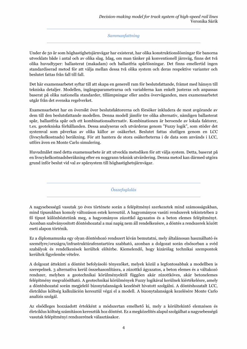
Aim of the study The aim of this study is to evaluate the different factors that globally or locally play a role in the decision on the type of track system and based on LCC calculations provide recommendation on which type of track system to choose of the 3 alternatives of ballasted track, ballastless track and alternating system option (ballastless track on structures and where geotechnical conditions are adequate, ballasted track otherwise, transition zones in between). In order to evaluate the uncertainties of the LCC calculation a Monte Carlo analysis shall be executed as well. On Figure 1 the proposed model can be observed. A 3-level algorithm is developed for the decision-making process, 2 levels aiming to create the alternating system option alternative based on local and global factors and the third level is an LCC calculation, based on the result of which the decision is made. The results of the LCC analysis is evaluated through a Monte Carlo analysis.
Figure 1 – Overview of decision-making model
Decision-making model for track system of high-speed rail lines Veronika Sárik
10
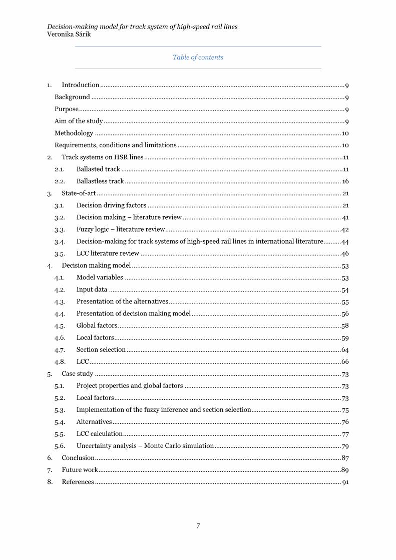
Methodology A literature study is conducted over the development of the conventional ballasted track and the main categories of ballastless track systems are described. Following this, the different factors influencing the choice of system are listed and described in detail based on literature study and expert consultation through series of interviews. Literature study has been conducted to provide overview on state-of-art regarding decision making models, fuzzy logic, LCC calculation and Monte Carlo simulation. Information and expertise on these topics have also been gained through interviews with experts of the respective fields. To provide a show case for the proposed decision-making model, a case study has been put forward. In order to gain knowledge from every relevant segment from the railway industry, numerous actors have been contacted and interviewed. 25 direct interviews have been conducted either in emails, via online meetings or in person. Figure 2 shows an overview about the area of the contacted experts, their companies and the number of persons contacted in the respective companies. Moreover, on one of the professional social media sites a group has been established to discuss the arising questions about choice between ballasted and ballastless track. As of today, the group counts over 150 members in total.
Figure 2 – Competency and contact map
Requirements, conditions and limitations The thesis offers a framework, a methodology for decision making, but it is to be noted, that all input values used are topic of discussion and can be changed. Expert opinions differ, so do conventions, practices and costs in different countries, thus a value applicable for one interested party might not be suitable for another. The author does not claim the hereby presented values generic, it is the methodology that is regarded as main contribution or added value, rather than the results. During the following study the numerous factors were taken into consideration during the decision-making process, but some important factors were only presented, not included in the model. These had to be excluded due to the scope of the thesis. These were e.g. availability, type of the traffic, weather and climate effects, and most of the environmental effects. The thesis only aims to take the track considerations into account, other technical areas, such as signaling, catenary etc. questions are not discussed, although these are vital parts of the railway system and to have an entire system overview, these should also be regarded and taken into account.
Decision-making model for track system of high-speed rail lines Veronika Sárik
11
2. Track systems on HSR lines
More than 50 years have passed since the first high-speed trains have started to operate on the Japanese Shinkansen lines (1964) and it also has been more than 35 years ago that Europe has commenced to launch the first high-speed rail services in France (TGV- Train á Grande Vitesse, 1981). Since these days, the development of the track structures has been continuously carried out, resulting in a number of different designs. The 2 main categories of the superstructures are the conventional ballasted track and the ballastless track. In the following sections these will be introduced and some common designs will be described.
2.1. Ballasted track
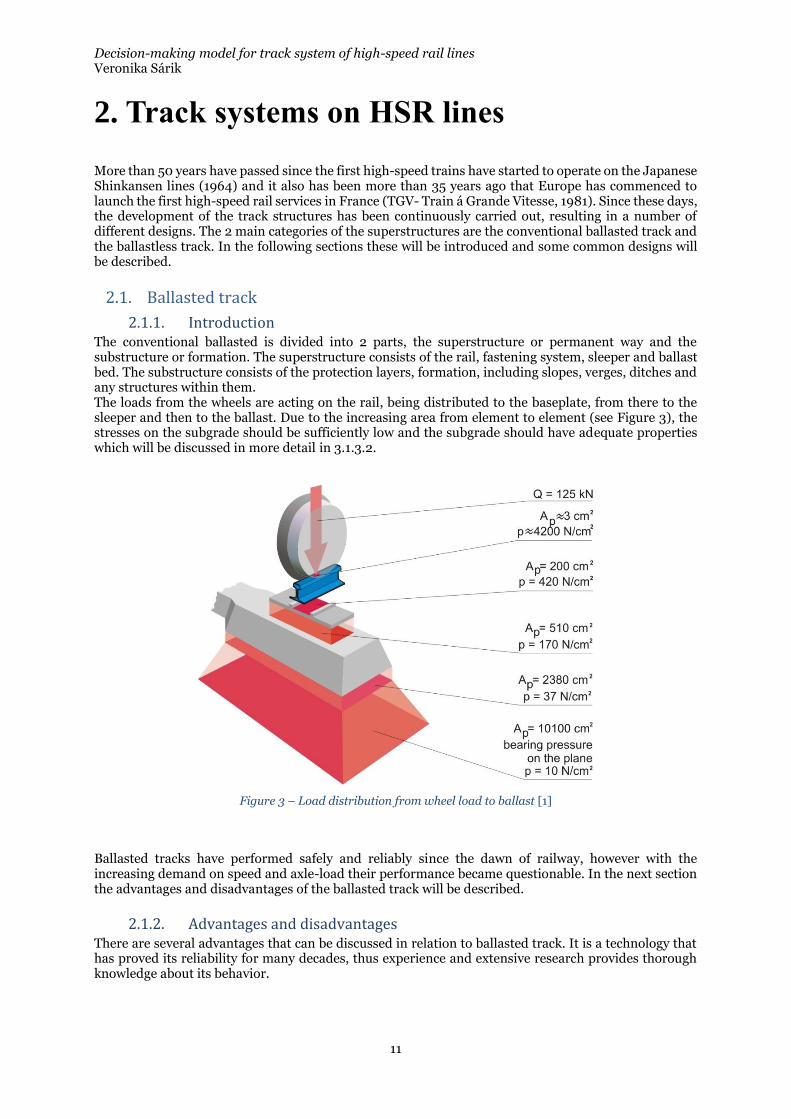
2.1.1. Introduction The conventional ballasted is divided into 2 parts, the superstructure or permanent way and the substructure or formation. The superstructure consists of the rail, fastening system, sleeper and ballast bed. The substructure consists of the protection layers, formation, including slopes, verges, ditches and any structures within them. The loads from the wheels are acting on the rail, being distributed to the baseplate, from there to the sleeper and then to the ballast. Due to the increasing area from element to element (see Figure 3), the stresses on the subgrade should be sufficiently low and the subgrade should have adequate properties which will be discussed in more detail in 3.1.3.2.
Figure 3 – Load distribution from wheel load to ballast [1]
Ballasted tracks have performed safely and reliably since the dawn of railway, however with the increasing demand on speed and axle-load their performance became questionable. In the next section the advantages and disadvantages of the ballasted track will be described.
2.1.2. Advantages and disadvantages There are several advantages that can be discussed in relation to ballasted track. It is a technology that has proved its reliability for many decades, thus experience and extensive research provides thorough knowledge about its behavior.
Decision-making model for track system of high-speed rail lines Veronika Sárik
12
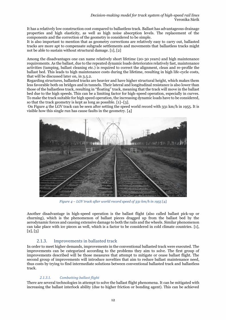
It has a relatively low construction cost compared to ballastless track. Ballast has advantageous drainage properties and high elasticity, as well as high noise absorption levels. The replacement of the components and the correction of the geometry is considered to be simple. It is also important to mention that as geometry corrections are relatively easy to carry out, ballasted tracks are more apt to compensate subgrade settlements and movements that ballastless tracks might not be able to sustain without structural damage. [1], [2] Among the disadvantages one can name relatively short lifetime (20-30 years) and high maintenance requirements. As the ballast, due to the repeated dynamic loads deteriorates relatively fast, maintenance activities (tamping, ballast cleaning etc.) is required to correct the alignment, clean and re-profile the ballast bed. This leads to high maintenance costs during the lifetime, resulting in high life-cycle costs, that will be discussed later on, in 3.5.2. Regarding structures, ballasted tracks are heavier and have higher structural height, which makes them less favorable both on bridges and in tunnels. Their lateral and longitudinal resistance is also lower than those of the ballastless track, resulting in “floating” track, meaning that the track will move in the ballast bed due to the high speeds. This can be a limiting factor for high-speed operation, especially in curves. To make the track suitable for high speed operation, the increasing dynamic loads have to be considered, so that the track geometry is kept as long as possible. [1]–[3]. On Figure 4 the LGV track can be seen after setting the speed world record with 331 km/h in 1955. It is visible how this single run has cause faults in the geometry. [4]
Figure 4 – LGV track after world record speed of 331 km/h in 1955 [4]
Another disadvantage in high-speed operation is the ballast flight (also called ballast pick-up or churning), which is the phenomenon of ballast pieces dragged up from the ballast bed by the aerodynamic forces and causing extensive damage to both the rails and the wheels. Similar phenomenon can take place with ice pieces as well, which is a factor to be considered in cold climate countries. [1], [2], [5]
2.1.3. Improvements in ballasted track In order to meet higher demands, improvements in the conventional ballasted track were executed. The improvements can be categorized according to the problems they aim to solve. The first group of improvements described will be those measures that attempt to mitigate or cease ballast flight. The second group of improvements will introduce novelties that aim to reduce ballast maintenance need, thus costs by trying to find intermediate solutions between conventional ballasted track and ballastless track.
2.1.3.1. Combatting ballast flight
There are several technologies in attempt to solve the ballast flight phenomena. It can be mitigated with increasing the ballast interlock ability (due to higher friction or bonding agent). This can be achieved
Decision-making model for track system of high-speed rail lines Veronika Sárik
13
with compacting the ballast or gluing the ballast pieces together. These methods are not widely used and there are no long-term experiences with them. Another way to proceed is modified ballast bed shape and mass. With reducing the height of the ballast shoulder and the ballast crib, the ballast flight can be mitigated or possibly avoided. It is also common to equip the rolling stock with armor to withstand and protect from the impact from the ballast pieces. [5], [6]
2.1.3.2. Reducing need for maintenance
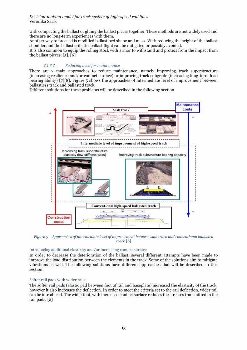
There are 2 main approaches to reduce maintenance, namely improving track superstructure (increasing resilience and/or contact surface) or improving track subgrade (increasing long-term load bearing ability) [7][8]. Figure 5 shows the approaches of intermediate level of improvement between ballastless track and ballasted track. Different solutions for these problems will be described in the following section.
Figure 5 – Approaches of intermediate level of improvement between slab track and conventional ballasted track [8]
Introducing additional elasticity and/or increasing contact surface
In order to decrease the deterioration of the ballast, several different attempts have been made to improve the load distribution between the elements in the track. Some of the solutions aim to mitigate vibrations as well. The following solutions have different approaches that will be described in this section.
Softer rail pads with wider rails
The softer rail pads (elastic pad between foot of rail and baseplate) increased the elasticity of the track, however it also increases the deflection. In order to meet the criteria set to the rail deflection, wider rail can be introduced. The wider foot, with increased contact surface reduces the stresses transmitted to the rail pads. [2]
Decision-making model for track system of high-speed rail lines Veronika Sárik
14
Highly elastic fasteners
It is also an option to use highly elastic fastenings to increase elasticity. This can be the ones used for ballastless track or specially developed ones for ballasted tracks. This solution, according to conducted studies results in decreased vibration on high-speed lines. [1], [2]
USP - Under Sleeper Pads
It is becoming common practice to use USPs (under sleeper pads) on heavy duty and/or high-speed lines. USPs are rubber or plastic pads mounted on the bottom of the sleeper. They introduce an extra element of elasticity in the track and the allow for penetration of the ballast pieces into their bottom surface, resulting in higher contact surface, thus lower contact stresses between sleeper and ballast. This phenomenon slows down the deterioration of the ballast and prolongs the maintenance intervals by up to 3-4 times. They can also be used in transition zones between track sections with different track stiffnesses, which will be discussed in 3.1.3.3. [9], [10]
Wider sleeper
The contact stresses on the ballast can also be reduced by using a bigger contact surface, increasing the area of the sleeper. Wide sleepers are currently in use in Germany, with very good results. The advantages include higher track bed and sideways stability, favorable deformation behavior and reduced maintenance requirements. The disadvantages with the system are that the tamping processes have to be adapted to the new layout, increased noise emission has been noted and that the construction cost is 10-20% higher, but this is expected to be compensated in medium-term. [1]
Frame sleeper track
“The frame sleeper track is a compromise between classical ballasted track and ballastless track.” [2] The cross sleepers, providing exact gauge for the rails are connected with longitudinal beams below the rails, constructing a frame-like structure. The contact pressure can be decreased with up to 50%, the frame sleeper provides high lateral resistance and stiffness that leads to a reduced settlements and a long-lasting track geometry. [1], [2]
Ladder sleeper
Another solution is to provide longitudinal beams below the rails, connected rigidly in transversal direction with steel pipes. This is the so-called ladder sleeper, developed in Japan. Laboratory tests have shown that the ladder sleeper solution ensures lower settlement (up to factor 8). [2]
Ballast mats
When the ballasted track is traverses on structures such as bridges or tunnels, extreme ballast strain occurs. This can be mitigated by using ballast mats, a resilient mat between ballast and the structure floor. Application of the ballast mats results in more uniform settlements [2]and vibration mitigation. [1]
Enhancing substructure
In order to decrease the need for maintenance and thus maintenance costs, another possible approach is to enhance the long-term bearing capacity of the substructure. This can be achieved by introducing additional stiffness with long-lasting materials between subgrade and ballast layer.
Asphalt layer
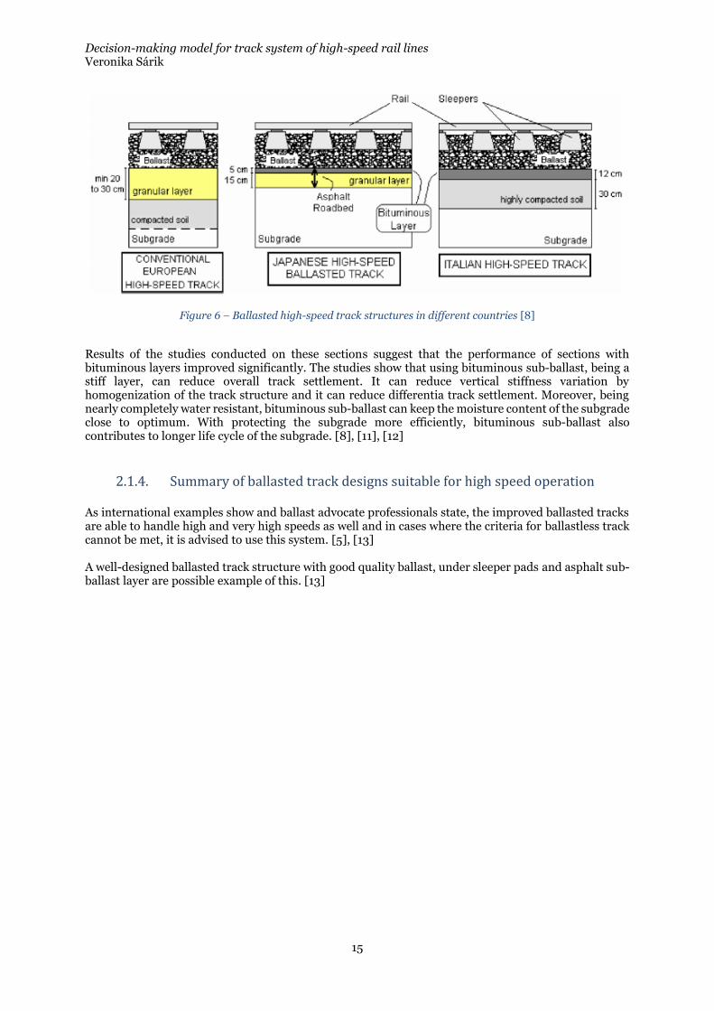
Using a bituminous layer in the sub-ballast layer has been proven a possible solution for the need of improvement in the substructure. This solution can be an alternative that reduces the thick ballast layers that ar e necessary to comply with the minimum bearing stiffness of the ballast bed on high-speed lines set in international standards. This method has been used in the United Stated on heavy traffic freight lines and on Italian, French and Japanese high-speed rail lines and a test section has been built in the Spanish HS system as well. [7], [8] A comparison between the conventional ballasted HS track, the Japanese and the Italian HS track can be seen in Figure 6.
Decision-making model for track system of high-speed rail lines Veronika Sárik
15
Figure 6 – Ballasted high-speed track structures in different countries [8]
Results of the studies conducted on these sections suggest that the performance of sections with bituminous layers improved significantly. The studies show that using bituminous sub-ballast, being a stiff layer, can reduce overall track settlement. It can reduce vertical stiffness variation by homogenization of the track structure and it can reduce differentia track settlement. Moreover, being nearly completely water resistant, bituminous sub-ballast can keep the moisture content of the subgrade close to optimum. With protecting the subgrade more efficiently, bituminous sub-ballast also contributes to longer life cycle of the subgrade. [8], [11], [12]
2.1.4. Summary of ballasted track designs suitable for high speed operation As international examples show and ballast advocate professionals state, the improved ballasted tracks are able to handle high and very high speeds as well and in cases where the criteria for ballastless track cannot be met, it is advised to use this system. [5], [13] A well-designed ballasted track structure with good quality ballast, under sleeper pads and asphalt sub-ballast layer are possible example of this. [13]
Decision-making model for track system of high-speed rail lines Veronika Sárik
16
2.2. Ballastless track In this chapter the other main track type will be presented, namely ballastless track. This type of track is also called ballast-free track, non-ballasted track, fixed track and slab track, however definitions might vary across literature. In this thesis, under the term ballastless track all track types are meant that use concrete or asphalt layers in the track instead of ballast. There are different solutions that have been implemented within this type of track, first the main categories will be presented, then some of the widely used products of different manufacturers will be described.
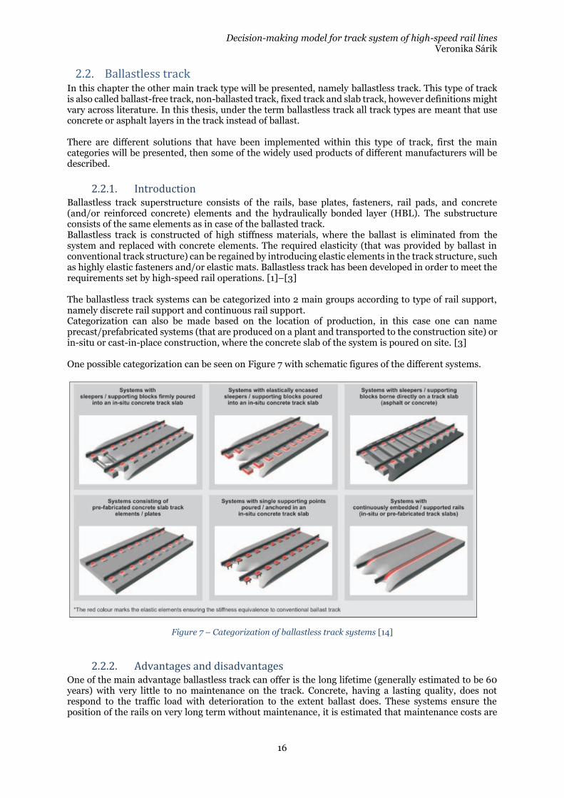
2.2.1. Introduction Ballastless track superstructure consists of the rails, base plates, fasteners, rail pads, and concrete (and/or reinforced concrete) elements and the hydraulically bonded layer (HBL). The substructure consists of the same elements as in case of the ballasted track. Ballastless track is constructed of high stiffness materials, where the ballast is eliminated from the system and replaced with concrete elements. The required elasticity (that was provided by ballast in conventional track structure) can be regained by introducing elastic elements in the track structure, such as highly elastic fasteners and/or elastic mats. Ballastless track has been developed in order to meet the requirements set by high-speed rail operations. [1]–[3] The ballastless track systems can be categorized into 2 main groups according to type of rail support, namely discrete rail support and continuous rail support. Categorization can also be made based on the location of production, in this case one can name precast/prefabricated systems (that are produced on a plant and transported to the construction site) or in-situ or cast-in-place construction, where the concrete slab of the system is poured on site. [3] One possible categorization can be seen on Figure 7 with schematic figures of the different systems.
Figure 7 – Categorization of ballastless track systems [14]
2.2.2. Advantages and disadvantages One of the main advantage ballastless track can offer is the long lifetime (generally estimated to be 60 years) with very little to no maintenance on the track. Concrete, having a lasting quality, does not respond to the traffic load with deterioration to the extent ballast does. These systems ensure the position of the rails on very long term without maintenance, it is estimated that maintenance costs are
Decision-making model for track system of high-speed rail lines Veronika Sárik
17
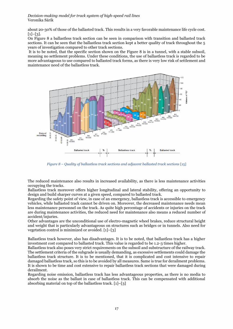
about 20-30% of those of the ballasted track. This results in a very favorable maintenance life cycle cost. [1]–[3]. On Figure 8 a ballastless track section can be seen in comparison with transition and ballasted track sections. It can be seen that the ballastless track section kept a better quality of track throughout the 5 years of investigation compared to other track sections. It is to be noted, that the specific section shown on the Figure 8 is in a tunnel, with a stable subsoil, meaning no settlement problems. Under these conditions, the use of ballastless track is regarded to be more advantageous to use compared to ballasted track forms, as there is very low risk of settlement and maintenance need of the ballastless track.
Figure 8 – Quality of ballastless track sections and adjacent ballasted track sections [15]
The reduced maintenance also results in increased availability, as there is less maintenance activities occupying the tracks. Ballastless track moreover offers higher longitudinal and lateral stability, offering an opportunity to design and build sharper curves at a given speed, compared to ballasted track. Regarding the safety point of view, in case of an emergency, ballastless track is accessible to emergency vehicles, while ballasted track cannot be driven on. Moreover, the decreased maintenance needs mean less maintenance personnel on the track. As quite high percentage of accidents or injuries on the track are during maintenance activities, the reduced need for maintenance also means a reduced number of accident/injuries. Other advantages are the unconditional use of electro-magnetic wheel brakes, reduce structural height and weight that is particularly advantageous on structures such as bridges or in tunnels. Also need for vegetation control is minimized or avoided. [1]–[3] Ballastless track however, also has disadvantages. It is to be noted, that ballastless track has a higher investment cost compared to ballasted track. This value is regarded to be 1.2-3 times higher. Ballastless track also poses very strict requirements on the subsoil and substructure of the railway track. The settlement criteria of the subgrade is usually demanding, as excessive settlements could damage the ballastless track structure. It is to be mentioned, that it is complicated and cost intensive to repair damaged ballastless track, so this is to be avoided by all measures. Same is true for derailment problems. It is shown to be time and cost extensive to repair ballastless track sections that were damaged during derailment. Regarding noise emission, ballastless track has less advantageous properties, as there is no media to absorb the noise as the ballast in case of ballastless track. This can be compensated with additional absorbing material on top of the ballastless track. [1]–[3]
Decision-making model for track system of high-speed rail lines Veronika Sárik
18
2.2.3. Ballastless track designs 2 of the widely known and used products in Europe will be shortly introduced and described in the following section, in order to give a general understanding of the concept of ballastless track, but without being exhaustive.
Example for prefabricated ballastless track system:
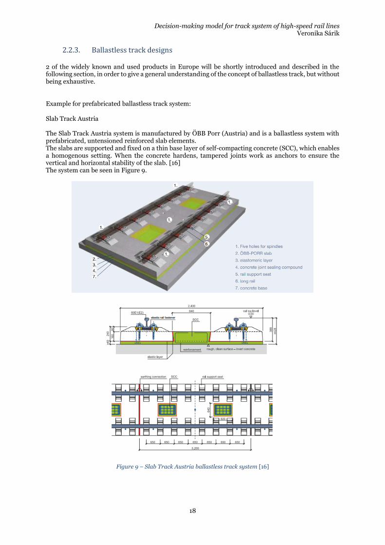
Slab Track Austria The Slab Track Austria system is manufactured by ÖBB Porr (Austria) and is a ballastless system with prefabricated, untensioned reinforced slab elements. The slabs are supported and fixed on a thin base layer of self-compacting concrete (SCC), which enables a homogenous setting. When the concrete hardens, tampered joints work as anchors to ensure the vertical and horizontal stability of the slab. [16] The system can be seen in Figure 9.
Figure 9 – Slab Track Austria ballastless track system [16]
Decision-making model for track system of high-speed rail lines Veronika Sárik
19
Example for in-situ ballastless track systems
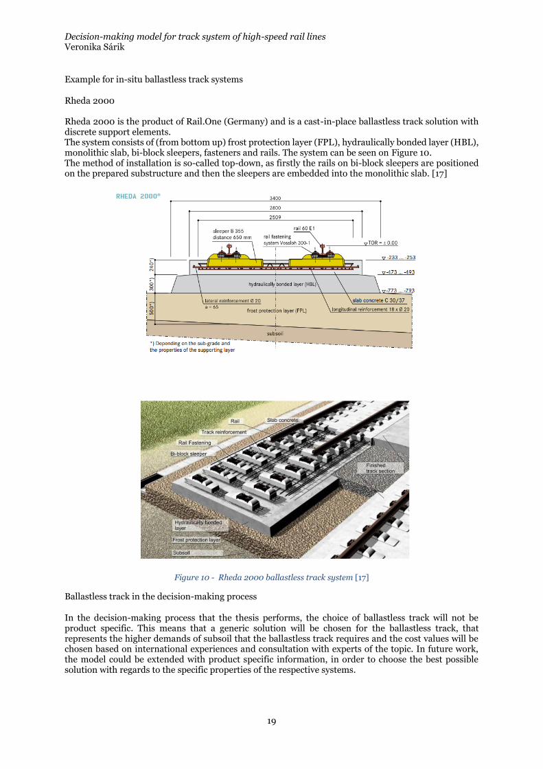
Rheda 2000 Rheda 2000 is the product of Rail.One (Germany) and is a cast-in-place ballastless track solution with discrete support elements. The system consists of (from bottom up) frost protection layer (FPL), hydraulically bonded layer (HBL), monolithic slab, bi-block sleepers, fasteners and rails. The system can be seen on Figure 10. The method of installation is so-called top-down, as firstly the rails on bi-block sleepers are positioned on the prepared substructure and then the sleepers are embedded into the monolithic slab. [17]
Figure 10 - Rheda 2000 ballastless track system [17]
Ballastless track in the decision-making process
In the decision-making process that the thesis performs, the choice of ballastless track will not be product specific. This means that a generic solution will be chosen for the ballastless track, that represents the higher demands of subsoil that the ballastless track requires and the cost values will be chosen based on international experiences and consultation with experts of the topic. In future work, the model could be extended with product specific information, in order to choose the best possible solution with regards to the specific properties of the respective systems.

Decision-making model for track system of high-speed rail lines Veronika Sárik
20
Decision-making model for track system of high-speed rail lines Veronika Sárik
21
3. State-of-art
In the following section, the state-of-art relevant to this work will be carried out. The first field of interest is the factors that influence the decision when selecting ballasted or ballastless track system for a newly built high-speed rail line. The Swedish requirements on these factors will also be overviewed. After assessing these factors, very brief summary of the decision-making tools used in this thesis will be overviewed. The proposed model uses the fuzzy set theory, which will also be reviewed in this section. Finally, a short state-of-art of LCC will be carried out.
3.1. Decision driving factors
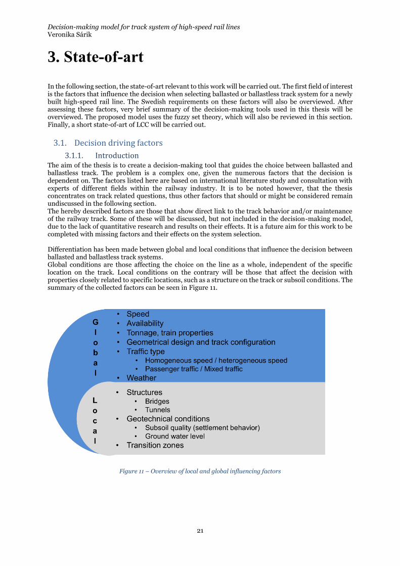
3.1.1. Introduction The aim of the thesis is to create a decision-making tool that guides the choice between ballasted and ballastless track. The problem is a complex one, given the numerous factors that the decision is dependent on. The factors listed here are based on international literature study and consultation with experts of different fields within the railway industry. It is to be noted however, that the thesis concentrates on track related questions, thus other factors that should or might be considered remain undiscussed in the following section. The hereby described factors are those that show direct link to the track behavior and/or maintenance of the railway track. Some of these will be discussed, but not included in the decision-making model, due to the lack of quantitative research and results on their effects. It is a future aim for this work to be completed with missing factors and their effects on the system selection. Differentiation has been made between global and local conditions that influence the decision between ballasted and ballastless track systems. Global conditions are those affecting the choice on the line as a whole, independent of the specific location on the track. Local conditions on the contrary will be those that affect the decision with properties closely related to specific locations, such as a structure on the track or subsoil conditions. The summary of the collected factors can be seen in Figure 11.
Figure 11 – Overview of local and global influencing factors
Decision-making model for track system of high-speed rail lines Veronika Sárik
22
3.1.2. Global conditions:
3.1.2.1. Design speed and availability
The design speed is one of the most meaningful properties of the railway line. The design process is based on the design speed, thus all geometric properties (radius of curves, cant etc.) will have to comply with criteria set by the design speed. According to UIC (International Union of Railways) there is no single definition of high speed, but generally the category of high-speed rail is used for upgraded lines from 200 km/h (or 220 km/h) and from new lines over 250 km/h. This thesis only considers newly built high-speed rail lines, thus the speed limit for high speed operation is set at 250 km/h, means P1 traffic category according to the categorization in the Technical Specifications for Interoperability – Infrastructure subsystem (TSI Infrastructure). [18] The increasing speeds that are introduced in high speed operation generate increased dynamic loads. The track has to cope with these loads, which in case of the ballasted track usually leads to higher deterioration. However, on high speed tracks the geometry criteria of the track are high, thus the deviations from the original geometry due to the deterioration have to be eliminated. This is done by maintenance processes (ballast tamping, rail grinding etc.) that might occur very often in order to keep the geometry within the allowed limit. In case of ballastless track this is less of an issue, as the ballast is eliminated from the system. Usually there is no need of maintaining the concrete as designed so its performance is assured throughout its lifetime in the track, thus ballastless track systems offer high availability. It is to be mentioned however, that if there is need of maintenance on ballastless track (because of e.g. derailment or faulty design), it might take considerably longer to correct it, in comparison with the ballasted track. During operation of a railway line, there is a so-called maintenance window, where there is no traffic on the line (usually during the night). If the required maintenance can be performed in this period, the traffic is undisturbed. However, if the maintenance requirement cannot be fulfilled during the maintenance window, the availability of the track decreases considerably, the traffic is disturbed (as the line has to be closed and trains cancelled, delayed or re-routed). As it shows, speed and availability are strongly linked. If a line with high speed operation is built, it is expected to offer high availability. As ballastless track is attributed to have very high availability (due to close to zero maintenance), it is becoming a viable option for the high-speed lines, despite its higher investment cost. In case of lower speeds (and thus lower availability requirements), the investment cost of the ballastless systems can be overwhelming, and despite the many advantageous properties of these systems, this option would be ruled out. It is to be understood, that system selection is generally based on financial considerations that usually drive huge infrastructural investments, such as a railway line. Thus in case of high speed rail lines, speed and availability can be main decision driving factors and has to be integrated into the evaluation of system selection.
3.1.2.2. Traffic load and train properties
In order to have a safe and efficient high speed operation, it is of great importance to have lightweight equipment, in order to increase energy efficiency, reduce noise levels, reduce wear and tear both on infrastructure and rolling stock and consequently maintenance costs. Unsprung mass of the bogies are also a factor that affects the deterioration to a great extent. Thus in order to build a low-maintenance high speed rail line, it is of crucial importance, that the train sets are also designed in accordance with the track system. However purchase of rolling stock is usually adapted to the chosen track system, there will be no in depth evaluation of the different aspects of rolling stock in this work. Regarding general properties of the train sets with respect to their effect to the track, it can be stated that there is a direct link between the degradation of the track and the accumulated traffic load or tonnage (usually expressed in Mega Gross Ton – MGT or Equivalent Mega Gross Ton – EMGT or Equivalent Mega Gross Ton Per Annum - EMGTPA). The tonnage is calculated based on the weight of the equipment and the cargo. The limiting value for the gross weight of a railway car is called axle load and is expressed usually in tons. The axle load can be defined as the weight resting on 1 axle when the gross weight of the train distributed on all of it axles.
Decision-making model for track system of high-speed rail lines Veronika Sárik
23
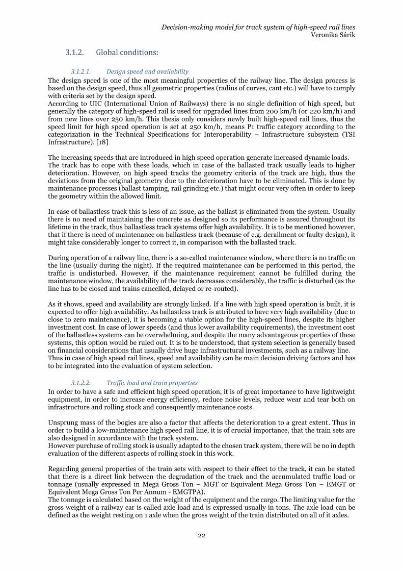
The higher the axle load, the higher the MGT (at given amount of trains and train lengths), the more deterioration will happen over time. Regarding energy efficiency, lightweight equipment is also important to be able to operate on high speeds. For these reason, the axle load is limited for high speed and the maintenance intervals are usually expressed in terms of MGT. The high speed trains (v>250km/h) in Europe are allowed to operate with a maximum of 17t axle loads, this is considerably lower compared to the conventional passenger and freight trains (20-22,5t). [18]
Table 1 – Performance parameters for passenger traffic [18]
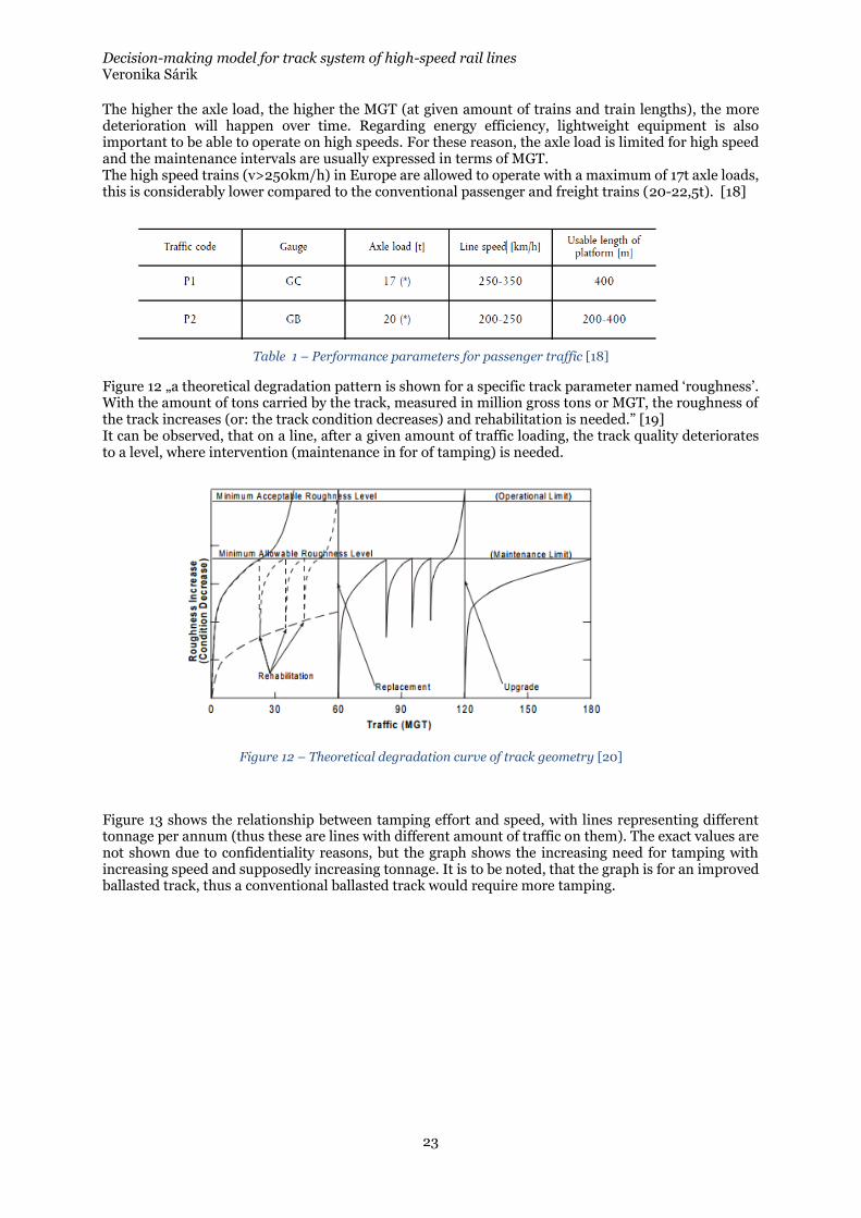
Figure 12 „a theoretical degradation pattern is shown for a specific track parameter named ‘roughness’. With the amount of tons carried by the track, measured in million gross tons or MGT, the roughness of the track increases (or: the track condition decreases) and rehabilitation is needed.” [19] It can be observed, that on a line, after a given amount of traffic loading, the track quality deteriorates to a level, where intervention (maintenance in for of tamping) is needed.
Figure 12 – Theoretical degradation curve of track geometry [20]
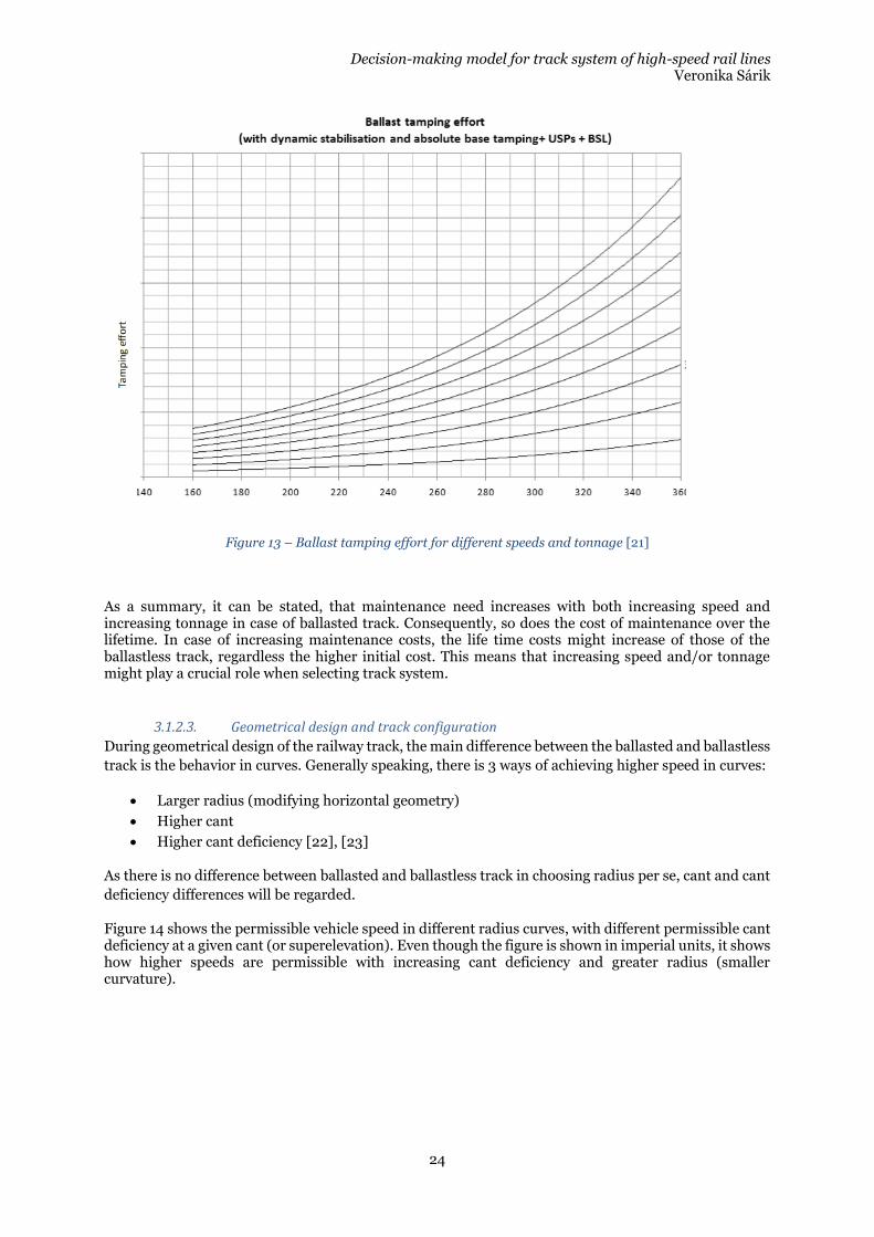
Figure 13 shows the relationship between tamping effort and speed, with lines representing different tonnage per annum (thus these are lines with different amount of traffic on them). The exact values are not shown due to confidentiality reasons, but the graph shows the increasing need for tamping with increasing speed and supposedly increasing tonnage. It is to be noted, that the graph is for an improved ballasted track, thus a conventional ballasted track would require more tamping.
Decision-making model for track system of high-speed rail lines Veronika Sárik
24
Figure 13 – Ballast tamping effort for different speeds and tonnage [21]
As a summary, it can be stated, that maintenance need increases with both increasing speed and increasing tonnage in case of ballasted track. Consequently, so does the cost of maintenance over the lifetime. In case of increasing maintenance costs, the life time costs might increase of those of the ballastless track, regardless the higher initial cost. This means that increasing speed and/or tonnage might play a crucial role when selecting track system.
3.1.2.3. Geometrical design and track configuration
During geometrical design of the railway track, the main difference between the ballasted and ballastless
track is the behavior in curves. Generally speaking, there is 3 ways of achieving higher speed in curves:
• Larger radius (modifying horizontal geometry)
• Higher cant
• Higher cant deficiency [22], [23]
As there is no difference between ballasted and ballastless track in choosing radius per se, cant and cant
deficiency differences will be regarded.
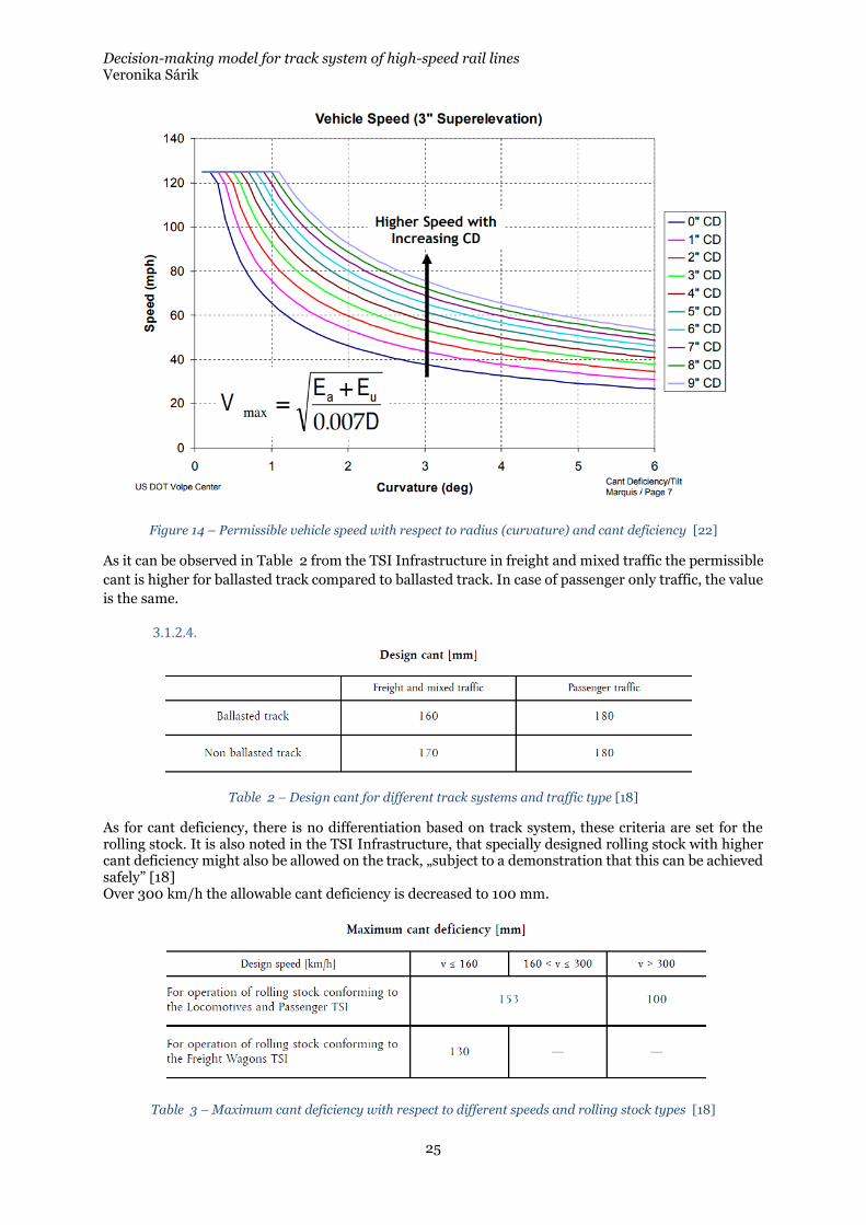
Figure 14 shows the permissible vehicle speed in different radius curves, with different permissible cant deficiency at a given cant (or superelevation). Even though the figure is shown in imperial units, it shows how higher speeds are permissible with increasing cant deficiency and greater radius (smaller curvature).
Decision-making model for track system of high-speed rail lines Veronika Sárik
25
Figure 14 – Permissible vehicle speed with respect to radius (curvature) and cant deficiency [22]
As it can be observed in Table 2 from the TSI Infrastructure in freight and mixed traffic the permissible
cant is higher for ballasted track compared to ballasted track. In case of passenger only traffic, the value
is the same.
3.1.2.4.
Table 2 – Design cant for different track systems and traffic type [18]
As for cant deficiency, there is no differentiation based on track system, these criteria are set for the rolling stock. It is also noted in the TSI Infrastructure, that specially designed rolling stock with higher cant deficiency might also be allowed on the track, „subject to a demonstration that this can be achieved safely” [18] Over 300 km/h the allowable cant deficiency is decreased to 100 mm.
Table 3 – Maximum cant deficiency with respect to different speeds and rolling stock types [18]
Decision-making model for track system of high-speed rail lines Veronika Sárik
26
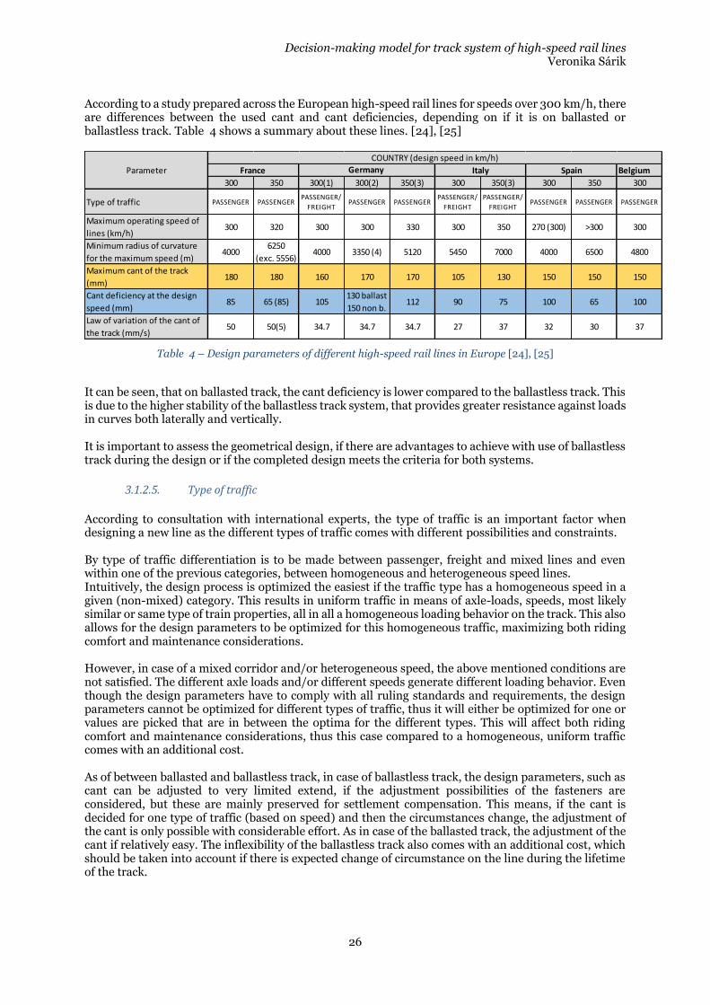
According to a study prepared across the European high-speed rail lines for speeds over 300 km/h, there are differences between the used cant and cant deficiencies, depending on if it is on ballasted or ballastless track. Table 4 shows a summary about these lines. [24], [25]
Table 4 – Design parameters of different high-speed rail lines in Europe [24], [25]
It can be seen, that on ballasted track, the cant deficiency is lower compared to the ballastless track. This is due to the higher stability of the ballastless track system, that provides greater resistance against loads in curves both laterally and vertically. It is important to assess the geometrical design, if there are advantages to achieve with use of ballastless track during the design or if the completed design meets the criteria for both systems.
3.1.2.5. Type of traffic
According to consultation with international experts, the type of traffic is an important factor when designing a new line as the different types of traffic comes with different possibilities and constraints. By type of traffic differentiation is to be made between passenger, freight and mixed lines and even within one of the previous categories, between homogeneous and heterogeneous speed lines. Intuitively, the design process is optimized the easiest if the traffic type has a homogeneous speed in a given (non-mixed) category. This results in uniform traffic in means of axle-loads, speeds, most likely similar or same type of train properties, all in all a homogeneous loading behavior on the track. This also allows for the design parameters to be optimized for this homogeneous traffic, maximizing both riding comfort and maintenance considerations. However, in case of a mixed corridor and/or heterogeneous speed, the above mentioned conditions are not satisfied. The different axle loads and/or different speeds generate different loading behavior. Even though the design parameters have to comply with all ruling standards and requirements, the design parameters cannot be optimized for different types of traffic, thus it will either be optimized for one or values are picked that are in between the optima for the different types. This will affect both riding comfort and maintenance considerations, thus this case compared to a homogeneous, uniform traffic comes with an additional cost. As of between ballasted and ballastless track, in case of ballastless track, the design parameters, such as cant can be adjusted to very limited extend, if the adjustment possibilities of the fasteners are considered, but these are mainly preserved for settlement compensation. This means, if the cant is decided for one type of traffic (based on speed) and then the circumstances change, the adjustment of the cant is only possible with considerable effort. As in case of the ballasted track, the adjustment of the cant if relatively easy. The inflexibility of the ballastless track also comes with an additional cost, which should be taken into account if there is expected change of circumstance on the line during the lifetime of the track.
Belgium
300 350 300(1) 300(2) 350(3) 300 350(3) 300 350 300
Type of traffic PASSENGER PASSENGERPASSENGER/
FREIGHTPASSENGER PASSENGER
PASSENGER/
FREIGHT
PASSENGER/
FREIGHTPASSENGER PASSENGER PASSENGER
Maximum operating speed of
lines (km/h)300 320 300 300 330 300 350 270 (300) >300 300
Minimum radius of curvature
for the maximum speed (m)4000
6250
(exc. 5556)4000 3350 (4) 5120 5450 7000 4000 6500 4800
Maximum cant of the track
(mm)180 180 160 170 170 105 130 150 150 150
Cant deficiency at the design
speed (mm) 85 65 (85) 105
130 ballast
150 non b.112 90 75 100 65 100
Law of variation of the cant of
the track (mm/s) 50 50(5) 34.7 34.7 34.7 27 37 32 30 37
Maximum gradient (mm/m) 35 35 20 40 40 12(6) 12(6) 12.5 25 15-21(6)
Maximum vertical radius (m) 16000 2100014000
'12000
14000
'1200020000 25000 25000
24000
(17000)25000
+20000
-17000
Parameter France Germany Italy Spain
COUNTRY (design speed in km/h)
Decision-making model for track system of high-speed rail lines Veronika Sárik
27
3.1.2.6. Environmental considerations
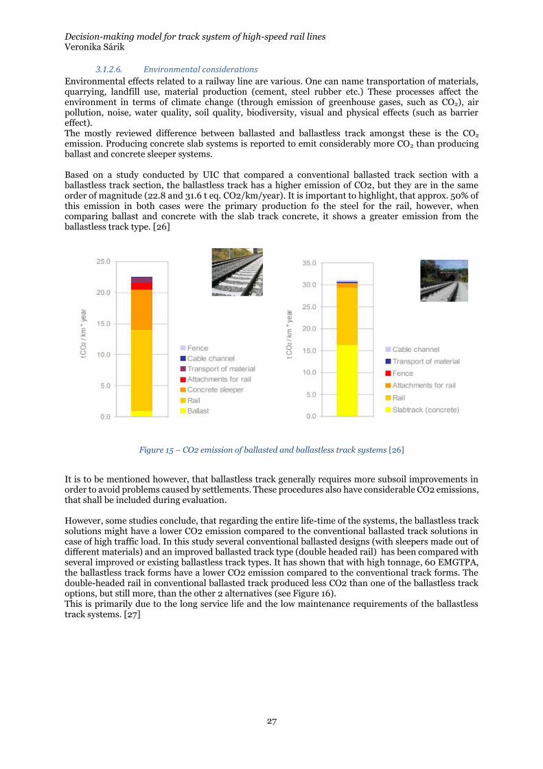
Environmental effects related to a railway line are various. One can name transportation of materials, quarrying, landfill use, material production (cement, steel rubber etc.) These processes affect the environment in terms of climate change (through emission of greenhouse gases, such as CO2), air pollution, noise, water quality, soil quality, biodiversity, visual and physical effects (such as barrier effect). The mostly reviewed difference between ballasted and ballastless track amongst these is the CO2 emission. Producing concrete slab systems is reported to emit considerably more CO2 than producing ballast and concrete sleeper systems. Based on a study conducted by UIC that compared a conventional ballasted track section with a ballastless track section, the ballastless track has a higher emission of CO2, but they are in the same order of magnitude (22.8 and 31.6 t eq. CO2/km/year). It is important to highlight, that approx. 50% of this emission in both cases were the primary production fo the steel for the rail, however, when comparing ballast and concrete with the slab track concrete, it shows a greater emission from the ballastless track type. [26]
Figure 15 – CO2 emission of ballasted and ballastless track systems [26]
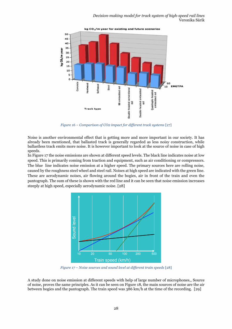
It is to be mentioned however, that ballastless track generally requires more subsoil improvements in order to avoid problems caused by settlements. These procedures also have considerable CO2 emissions, that shall be included during evaluation. However, some studies conclude, that regarding the entire life-time of the systems, the ballastless track solutions might have a lower CO2 emission compared to the conventional ballasted track solutions in case of high traffic load. In this study several conventional ballasted designs (with sleepers made out of different materials) and an improved ballasted track type (double headed rail) has been compared with several improved or existing ballastless track types. It has shown that with high tonnage, 60 EMGTPA, the ballastless track forms have a lower CO2 emission compared to the conventional track forms. The double-headed rail in conventional ballasted track produced less CO2 than one of the ballastless track options, but still more, than the other 2 alternatives (see Figure 16). This is primarily due to the long service life and the low maintenance requirements of the ballastless track systems. [27]
Decision-making model for track system of high-speed rail lines Veronika Sárik
28
Figure 16 – Comparison of CO2 impact for different track systems [27]
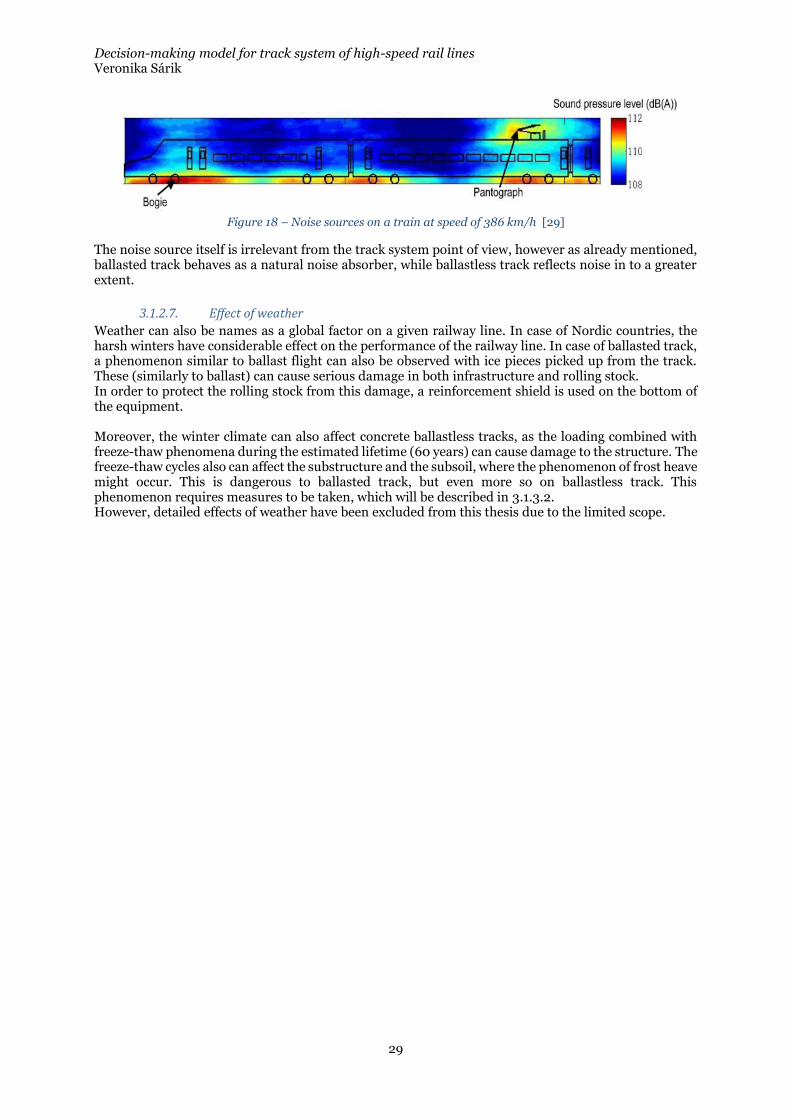
Noise is another environmental effect that is getting more and more important in our society. It has already been mentioned, that ballasted track is generally regarded as less noisy construction, while ballastless track emits more noise. It is however important to look at the source of noise in case of high speeds. In Figure 17 the noise emissions are shown at different speed levels. The black line indicates noise at low
speed. This is primarily coming from traction and equipment, such as air conditioning or compressors.
The blue line indicates noise emission at a higher speed. The primary sources here are rolling noise,
caused by the roughness steel wheel and steel rail. Noises at high speed are indicated with the green line.
These are aerodynamic noises, air flowing around the bogies, air in front of the train and even the
pantograph. The sum of these is shown with the red line and it can be seen that noise emission increases
steeply at high speed, especially aerodynamic noise. [28]
Figure 17 – Noise sources and sound level at different train speeds [28]
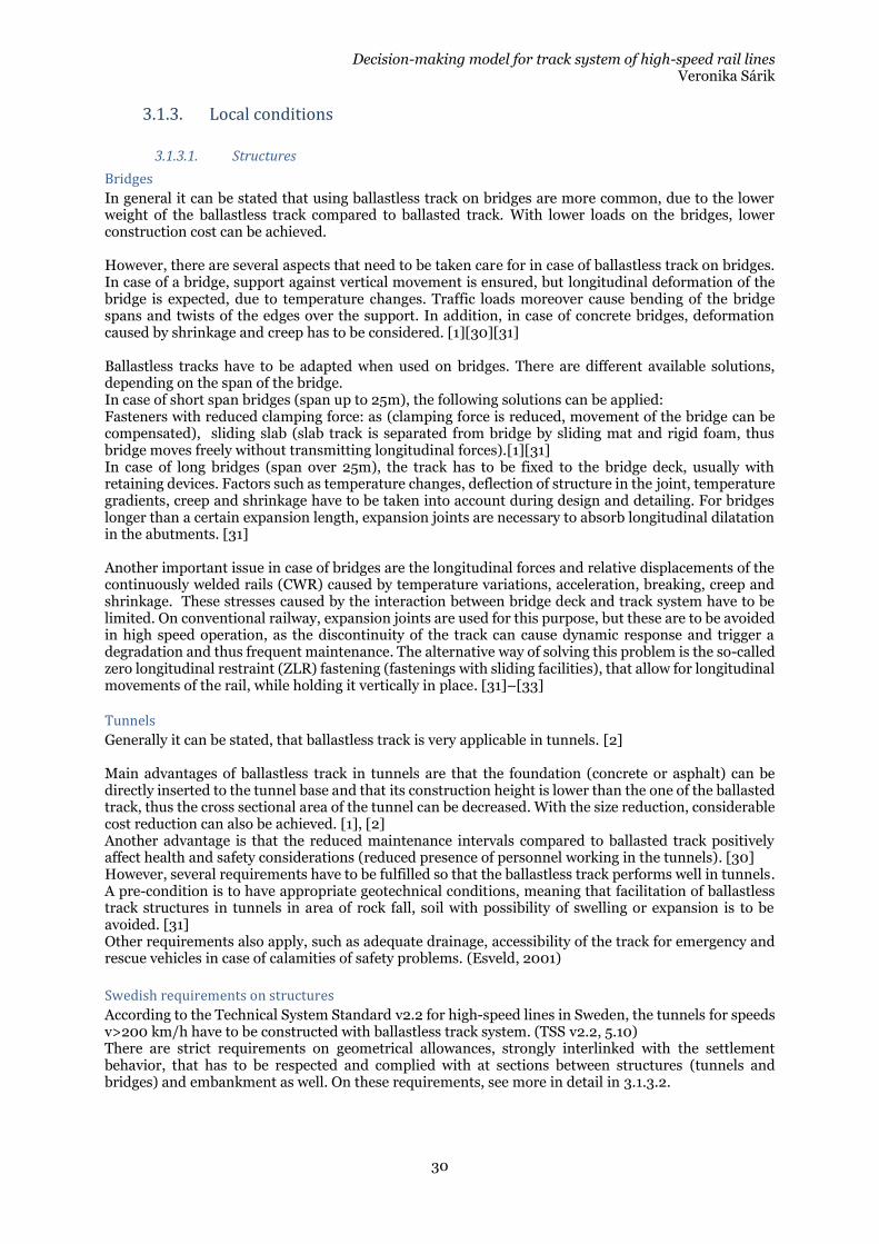
A study done on noise emission at different speeds with help of large number of microphones,, Source of noise, proves the same principles. As it can be seen on Figure 18, the main sources of noise are the air between bogies and the pantograph. The train speed was 386 km/h at the time of the recording. [29]
Decision-making model for track system of high-speed rail lines Veronika Sárik
29
Figure 18 – Noise sources on a train at speed of 386 km/h [29]
The noise source itself is irrelevant from the track system point of view, however as already mentioned, ballasted track behaves as a natural noise absorber, while ballastless track reflects noise in to a greater extent.
3.1.2.7. Effect of weather
Weather can also be names as a global factor on a given railway line. In case of Nordic countries, the harsh winters have considerable effect on the performance of the railway line. In case of ballasted track, a phenomenon similar to ballast flight can also be observed with ice pieces picked up from the track. These (similarly to ballast) can cause serious damage in both infrastructure and rolling stock. In order to protect the rolling stock from this damage, a reinforcement shield is used on the bottom of the equipment. Moreover, the winter climate can also affect concrete ballastless tracks, as the loading combined with freeze-thaw phenomena during the estimated lifetime (60 years) can cause damage to the structure. The freeze-thaw cycles also can affect the substructure and the subsoil, where the phenomenon of frost heave might occur. This is dangerous to ballasted track, but even more so on ballastless track. This phenomenon requires measures to be taken, which will be described in 3.1.3.2. However, detailed effects of weather have been excluded from this thesis due to the limited scope.
Decision-making model for track system of high-speed rail lines Veronika Sárik
30
3.1.3. Local conditions
3.1.3.1. Structures
Bridges
In general it can be stated that using ballastless track on bridges are more common, due to the lower weight of the ballastless track compared to ballasted track. With lower loads on the bridges, lower construction cost can be achieved. However, there are several aspects that need to be taken care for in case of ballastless track on bridges. In case of a bridge, support against vertical movement is ensured, but longitudinal deformation of the bridge is expected, due to temperature changes. Traffic loads moreover cause bending of the bridge spans and twists of the edges over the support. In addition, in case of concrete bridges, deformation caused by shrinkage and creep has to be considered. [1][30][31] Ballastless tracks have to be adapted when used on bridges. There are different available solutions, depending on the span of the bridge. In case of short span bridges (span up to 25m), the following solutions can be applied: Fasteners with reduced clamping force: as (clamping force is reduced, movement of the bridge can be compensated), sliding slab (slab track is separated from bridge by sliding mat and rigid foam, thus bridge moves freely without transmitting longitudinal forces).[1][31] In case of long bridges (span over 25m), the track has to be fixed to the bridge deck, usually with retaining devices. Factors such as temperature changes, deflection of structure in the joint, temperature gradients, creep and shrinkage have to be taken into account during design and detailing. For bridges longer than a certain expansion length, expansion joints are necessary to absorb longitudinal dilatation in the abutments. [31] Another important issue in case of bridges are the longitudinal forces and relative displacements of the continuously welded rails (CWR) caused by temperature variations, acceleration, breaking, creep and shrinkage. These stresses caused by the interaction between bridge deck and track system have to be limited. On conventional railway, expansion joints are used for this purpose, but these are to be avoided in high speed operation, as the discontinuity of the track can cause dynamic response and trigger a degradation and thus frequent maintenance. The alternative way of solving this problem is the so-called zero longitudinal restraint (ZLR) fastening (fastenings with sliding facilities), that allow for longitudinal movements of the rail, while holding it vertically in place. [31]–[33]
Tunnels
Generally it can be stated, that ballastless track is very applicable in tunnels. [2] Main advantages of ballastless track in tunnels are that the foundation (concrete or asphalt) can be directly inserted to the tunnel base and that its construction height is lower than the one of the ballasted track, thus the cross sectional area of the tunnel can be decreased. With the size reduction, considerable cost reduction can also be achieved. [1], [2] Another advantage is that the reduced maintenance intervals compared to ballasted track positively affect health and safety considerations (reduced presence of personnel working in the tunnels). [30] However, several requirements have to be fulfilled so that the ballastless track performs well in tunnels. A pre-condition is to have appropriate geotechnical conditions, meaning that facilitation of ballastless track structures in tunnels in area of rock fall, soil with possibility of swelling or expansion is to be avoided. [31] Other requirements also apply, such as adequate drainage, accessibility of the track for emergency and rescue vehicles in case of calamities of safety problems. (Esveld, 2001)
Swedish requirements on structures
According to the Technical System Standard v2.2 for high-speed lines in Sweden, the tunnels for speeds v>200 km/h have to be constructed with ballastless track system. (TSS v2.2, 5.10) There are strict requirements on geometrical allowances, strongly interlinked with the settlement behavior, that has to be respected and complied with at sections between structures (tunnels and bridges) and embankment as well. On these requirements, see more in detail in 3.1.3.2.
Decision-making model for track system of high-speed rail lines Veronika Sárik
31
3.1.3.2. Geotechnical considerations
As mentioned before, the railway track is divided into superstructure and substructure. The substructure consists of the frost protection layer and the subgrade. The subgrade is made out of (usually) compacted soil. The subsoil is the natural ground below the formation of the railway track. In order to keep the geometry according to design, all elements of the railway track shall support the principle to keep the rails in their original position. In order to do this the loads shall be transmitted and distributed to the extent that they do not cause deformation (over the allowable limits) in the subgrade and in the subsoil. However, for this to happen, all elements of the substructure shall also meet different criteria. It is important to highlight that the requirements differ in case of ballasted track and ballastless track, these will be discussed in this section.
Soils
There are different categorization systems according to which soils can be categorized. Probably the most basic one is the differentiation based on size. Soil particles with diameters less than 0.067 mm are called cohesive and soils with larger diameters are called non-cohesive or granular soil. Clay and silt are categorized as cohesion soils, while sand, gravel and rock are categorized as granular soils. For railway application, soil categories has been determined in UIC 719-R guideline. [34]
• QS0: the soil is unsuitable to serve as foundation without improvement
• QS1: the soil is suitable, given adequate drainage, reinforcement should eventually be considered to increase quality
• QS2: the soil is of average quality
• QS3: the soil if of good quality The categories are made based on the content of fine particles and organic soils, susceptibility for weathering, Microdewal and Los Angeles values.
Geotechnical investigations
Soils under transportation facilities have to sustain different kinds of effects. These include mechanical effects, such as vertical static loads (load of the vehicles), vertical dynamic loads (vibrations), and horizontal loads (braking). Climatic loads also apply on them, water content change, freezing and thawing phenomena all affect the performance of the soil. In order to evaluate if the specific soil is able to fulfill the requirements, different examinations have to be conducted, so that all soil parameters can be determined. These include:
• Discovery of soil properties and layers through ground probing or bore-holes
• Evaluation of deformation properties
• Evaluation of volume changing properties
• Evaluation of freeze-thaw behavior
• Evaluation of ground-water level
Discovery of soil properties
In order to have an understanding of the soil conditions below the planned railway line, geotechnical evaluation is executed through probing or bore-holes.
Probing is method during which a steel rod is used to assess the soil conditions. The probe is driven down to the soil and based on the driving resistance and the particles adhering to the rod the type and properties of the soil is evaluated.
During boring, bore-holes are created in the soil and samples are collected and evaluated. This method is more informative and reliable one, as it gives information on the type and depth of each strata of soil/rock and the ground water table as well. [35], [36]
There are different types of probing and boring, which will not be elaborated further in this work.
Decision-making model for track system of high-speed rail lines Veronika Sárik
32
During the assessment of geotechnical conditions below a newly planned high-speed rail line, soil investigations, usually boring is executed in given intervals. Based on international literature and consultations with experts, this interval can be estimated to be around 50m, with shorter intervals on sections with greater uncertainties regarding the soil conditions. [1]
The type and intervals of assessment is independent of the track systems.
Deformation properties
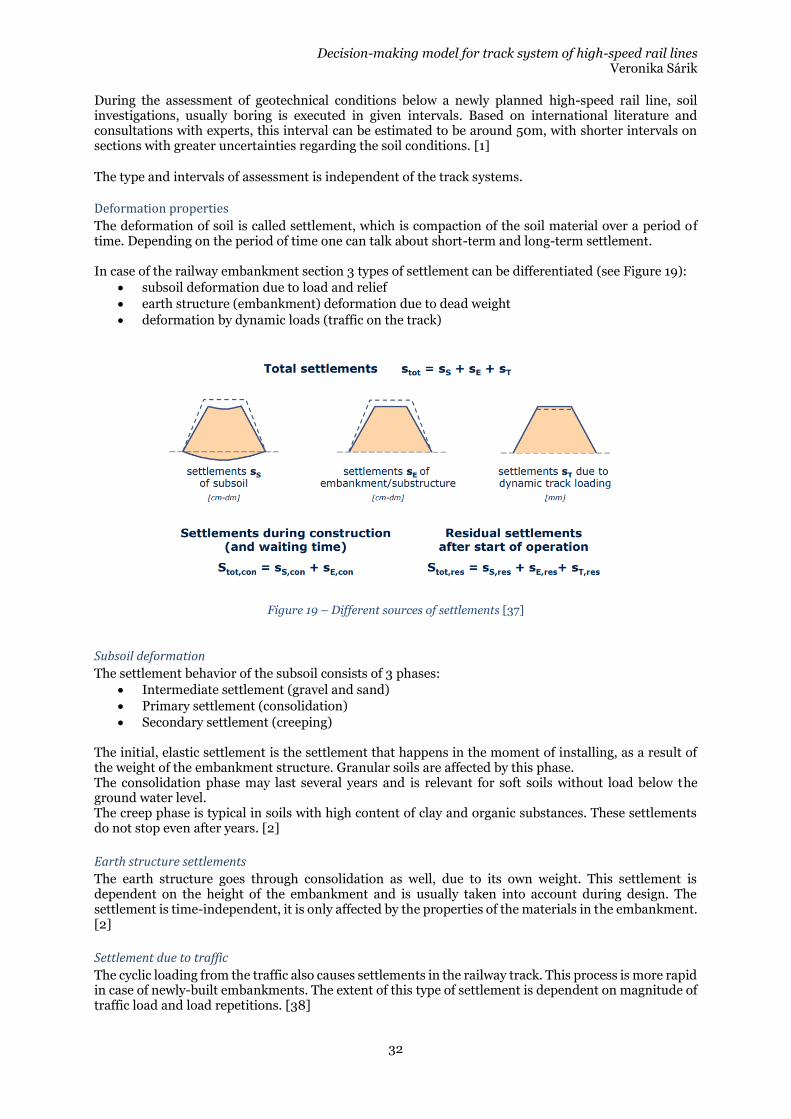
The deformation of soil is called settlement, which is compaction of the soil material over a period of time. Depending on the period of time one can talk about short-term and long-term settlement. In case of the railway embankment section 3 types of settlement can be differentiated (see Figure 19):
• subsoil deformation due to load and relief
• earth structure (embankment) deformation due to dead weight
• deformation by dynamic loads (traffic on the track)
Figure 19 – Different sources of settlements [37]
Subsoil deformation
The settlement behavior of the subsoil consists of 3 phases:
• Intermediate settlement (gravel and sand)
• Primary settlement (consolidation)
• Secondary settlement (creeping) The initial, elastic settlement is the settlement that happens in the moment of installing, as a result of the weight of the embankment structure. Granular soils are affected by this phase. The consolidation phase may last several years and is relevant for soft soils without load below the ground water level. The creep phase is typical in soils with high content of clay and organic substances. These settlements do not stop even after years. [2]
Earth structure settlements
The earth structure goes through consolidation as well, due to its own weight. This settlement is dependent on the height of the embankment and is usually taken into account during design. The settlement is time-independent, it is only affected by the properties of the materials in the embankment. [2]
Settlement due to traffic
The cyclic loading from the traffic also causes settlements in the railway track. This process is more rapid in case of newly-built embankments. The extent of this type of settlement is dependent on magnitude of traffic load and load repetitions. [38]
Decision-making model for track system of high-speed rail lines Veronika Sárik
33
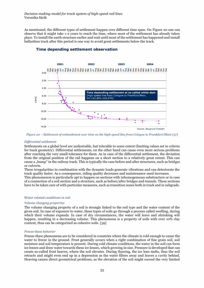
As mentioned, the different types of settlement happen over different time span. On Figure 20 one can observe that it might take 1-2 years to reach the time, where most of the settlement has already taken place. To install the earth structure earlier and wait until most of the settlement has happened and install ballastless track after this period is one way to avoid great settlements below the track.
Figure 20 – Settlement of embankment over time on the high-speed line from Cologne to Frankfurt/Main [37]
Differential settlement
Settlements on a global level are undesirable, but tolerable to some extent (limiting values set in criteria for track geometry). Differential settlements, on the other hand can cause even more serious problems after reaching the very small tolerance for them. As in case of the differential settlement, the deviation from the original position of the rail happens on a short section to a relatively great extent. This can cause a „bump” in the railway track. This is typically the case before and after structures, such as bridges or culverts. These irregularities in combination with the dynamic loads generate vibrations and can deteriorate the track quality faster. As a consequence, riding quality decreases and maintenance need increases. This phenomenon is particularly apt to happen on sections with inhomogeneous substructure or in case of a connection of a soil section and a structure, such as before/after bridges and tunnels. These sections have to be taken care of with particular measures, such as transition zones both in track and in subgrade.
Water related conditions in soil
Volume changing properties
The volume changing property of a soil is strongly linked to the soil type and the water content of the given soil. In case of exposure to water, these types of soils go through a process called swelling, during which their volume expands. In case of dry circumstances, the water will leave and shrinking will happen, resulting in a decreasing volume. This phenomena is a property of soils with over 10% clay content, thus can be categorized as cohesive soils. [39]
Freeze-thaw behavior
Freeze-thaw phenomena are to be considered in countries where the climate is cold enough to cause the water to freeze in the ground. Frost generally occurs when a right combination of fine grain soil, soil moisture and soil temperature is present. During cold climate conditions, the water in the soil can form ice lenses and draw water towards these ice lenses, which growing in size. Pressure is developed that can create so-called frost heaves, where the soil elevates. During thawing, the ice lens melts, thus the soil retracts and might even end up in a depression as the water filters away and leaves a cavity behind. Heaving causes direct geometrical problems, as the elevation of the soil might exceed the very limited
Decision-making model for track system of high-speed rail lines Veronika Sárik
34
allowance of railway geometry failures. During the thawing, the subsoil might not provide adequate support to the track anymore. [40] It is also to be mentioned, that on high-speed rail lines in cold climate conditions in China, a new frost phenomena has occurred, where the heaving happened in the embankment constructed from coarse materials, which in theory are not frost susceptible. [41] On these sections serious heaving (average 5mm, maximum 30mm) has been reported, which of course led to geometrical faults well above the limits. A new theory suggests, that it is possible that the cyclic loading of the high-speed trains contributed to the pumping of the water to the embankment and enables ice lenses to form there. The phenomenon is called pumping-enhanced frost heave. [42], [43]
Ground water level
The level of the ground water table is an important geotechnical property of a given location. Below this level the cavities between the soil particles are filled with water. This condition results in decreased load-bearing capacity. It is also important to understand the link between the ground water level and the previously discussed frost heave phenomenon. As long as the ice lenses have an uninterrupted access to excess water, they will grow, theoretically limitlessly. This is why it is utmost importance that the ground water level would be below the frost front. [43], [44]
Critical velocity – Reyleigh waves
Railway structures have a so-called critical velocity value which is dependent on the dimensions and material properties of the railway track. When the train speed reaches up to the wave propagation velocity of the supporting structure, vibrations and deflections occur to a great extent. This is a safety and maintenance problem, as the degradation might require more intensive maintenance or even expensive methods to reinforce the soil. [45]–[47] This particular matter however has not been investigated within the scope of this work. It can be stated, than on a well-designed earthwork, this should not cause a problem, but the phenomenon is one that needs to be taken into consideration. [1]
General requirements of subsoil and subgrade for high-speed railway tracks
Generally speaking, the requirements of subsoil and subgrade are higher in case of high speed rail than in case of conventional railway. This is due to the higher dynamic loads generated by the higher speeds. There are however even differences in the requirements on ballasted and ballastless track systems. Ballasted track, as mentioned before through ballast enables a more organically elastic track, while elasticity in case of ballastless track primarily comes from the additional elastic elements (fasteners, pads/mats). Ballasted track with the elasticity provided is able to cope with settlements of the subgrade to an extent that ballastless track cannot due to its rigidity. In case of the ballasted track, if the settlements and the caused geometric deviations exceed the limits, tamping is executed, additional ballast is integrated to the track and the geometry is restored. Settlements in case of ballastless track would cause stresses in the slab that could result in cracks or eventually actual break of the slab. Repairing a section that suffered damage this severe (as previously mentioned) would be time- and expense-extensive (as the subgrade would have to be cared for as well), thus this scenario is to be avoided by all measures. This results in increased requirements on the subgrade in case of ballastless track, which are presented in the following section. To ensure that settlements do not happen along the future tracks, expensive subgrade improvement technologies are to be used. These will be introduced and described in the following sections. Similarly, water content changes (swelling and shrinking) and freeze-thaw phenomena can cause the same problems, thus in order to avoid the occurrence of these, special measures are to be taken during the material use and the design of the cross sections. These will also be described in the following sections.
Decision-making model for track system of high-speed rail lines Veronika Sárik
35
Soil improvements
There are several technologies considered for improving the quality of the subsoil. These will be listed (without being exclusive) and shortly described in the following section.
Dynamic compacting
Dynamic compaction is a ground improvement technique that densifies soils and fill materials by using a drop weight. The drop weight, typically steel, is lifted by a crane and repeatedly dropped onto the ground surface. Vibrations transmitted below the surface improve soils at depth. The drop locations are typically located on a grid pattern, the spacing of which is determined by the subsurface conditions and foundation loading and geometry. [48]
Soil replacements
It is possible to excavate and then replace the subsoil with unsuitable quality (such as organic soil or soft clay), however this is not economical in great depths and generally practical only above groundwater table. The replacement can be made of granular material such as sand, gravel or crushed stones. [49]
Column-supported embankment/Pile-like bearing embankment
The main concept of column-supported or pile-like bearing embankments is that they transfer the embankment loads to a stiffer soil surface below the strata of low load-bearing capacity. Columns There are various solutions of supporting columns, such as stone columns, jet-grouted columns, soil-mixed columns, vibro-concrete columns, composite columns etc.
Soil mixing
Soil mixing is a ground improvement technology that is based on mixing soil with binding agents such as lime or cement, to improve its strength and stability. 2 types are differentiated, Shallow Soil Mixing and Deep Soil Mixing.
Shallow Soil Mixing (SSM)
Shallow Soil Mixing is generally used for loose and soft soil in shallow depth. The binding agent is blended with the soil material and forms a column of strengthened soil material. [50]
Deep Soil Mixing (DSM)
Deep mixing is a stabilization method for harder soils in great depth. During deep mixing the in-situ material is blended with a liquid or dry, lime, cement or fly-ash based mortar with a help of a mechanical or rotary mixing tool. [1], [51]
Grouting
During grouting a cement or lime based liquid mortar is injected to the soil, which hardens and thus improves the load bearing capacity of the soil. [1]
Piling
During the process piles are driven down to the soil in order to ensure load bearing. In case of end-bearing piles, the piles are driven through the soft strata until they reach the bedrock or moraine layer, that provides a base for load bearing. Friction piles provide load bearing through friction along the surface of the pile in the soil. On the piles, a long slab, several smaller slabs or geogrids are placed in order to ensure the load distribution and serve as a foundation for the embankment to be built on.
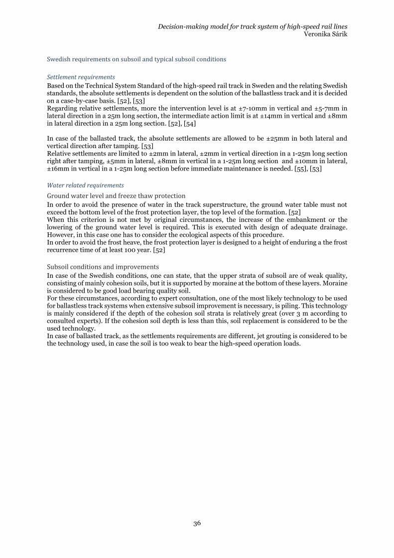
Decision-making model for track system of high-speed rail lines Veronika Sárik
36
Swedish requirements on subsoil and typical subsoil conditions
Settlement requirements
Based on the Technical System Standard of the high-speed rail track in Sweden and the relating Swedish standards, the absolute settlements is dependent on the solution of the ballastless track and it is decided on a case-by-case basis. [52], [53] Regarding relative settlements, more the intervention level is at ±7-10mm in vertical and ±5-7mm in lateral direction in a 25m long section, the intermediate action limit is at ±14mm in vertical and ±8mm in lateral direction in a 25m long section. [52], [54] In case of the ballasted track, the absolute settlements are allowed to be ±25mm in both lateral and vertical direction after tamping. [53] Relative settlements are limited to ±2mm in lateral, ±2mm in vertical direction in a 1-25m long section right after tamping, ±5mm in lateral, ±8mm in vertical in a 1-25m long section and ±10mm in lateral, ±16mm in vertical in a 1-25m long section before immediate maintenance is needed. [55], [53]
Water related requirements
Ground water level and freeze thaw protection
In order to avoid the presence of water in the track superstructure, the ground water table must not exceed the bottom level of the frost protection layer, the top level of the formation. [52] When this criterion is not met by original circumstances, the increase of the embankment or the lowering of the ground water level is required. This is executed with design of adequate drainage. However, in this case one has to consider the ecological aspects of this procedure. In order to avoid the frost heave, the frost protection layer is designed to a height of enduring a the frost recurrence time of at least 100 year. [52]
Subsoil conditions and improvements
In case of the Swedish conditions, one can state, that the upper strata of subsoil are of weak quality, consisting of mainly cohesion soils, but it is supported by moraine at the bottom of these layers. Moraine is considered to be good load bearing quality soil. For these circumstances, according to expert consultation, one of the most likely technology to be used for ballastless track systems when extensive subsoil improvement is necessary, is piling. This technology is mainly considered if the depth of the cohesion soil strata is relatively great (over 3 m according to consulted experts). If the cohesion soil depth is less than this, soil replacement is considered to be the used technology. In case of ballasted track, as the settlements requirements are different, jet grouting is considered to be the technology used, in case the soil is too weak to bear the high-speed operation loads.
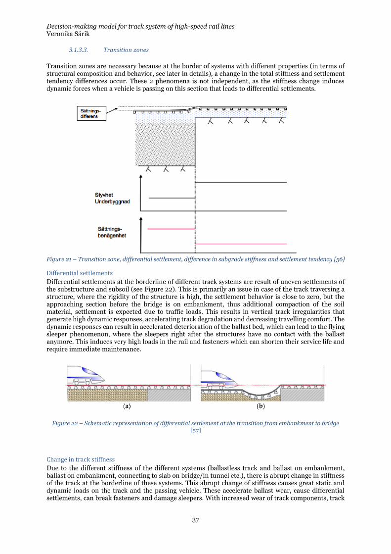
Decision-making model for track system of high-speed rail lines Veronika Sárik
37
3.1.3.3. Transition zones
Transition zones are necessary because at the border of systems with different properties (in terms of structural composition and behavior, see later in details), a change in the total stiffness and settlement tendency differences occur. These 2 phenomena is not independent, as the stiffness change induces dynamic forces when a vehicle is passing on this section that leads to differential settlements.
Figure 21 – Transition zone, differential settlement, difference in subgrade stiffness and settlement tendency [56]
Differential settlements
Differential settlements at the borderline of different track systems are result of uneven settlements of the substructure and subsoil (see Figure 22). This is primarily an issue in case of the track traversing a structure, where the rigidity of the structure is high, the settlement behavior is close to zero, but the approaching section before the bridge is on embankment, thus additional compaction of the soil material, settlement is expected due to traffic loads. This results in vertical track irregularities that generate high dynamic responses, accelerating track degradation and decreasing travelling comfort. The dynamic responses can result in accelerated deterioration of the ballast bed, which can lead to the flying sleeper phenomenon, where the sleepers right after the structures have no contact with the ballast anymore. This induces very high loads in the rail and fasteners which can shorten their service life and require immediate maintenance.
Figure 22 – Schematic representation of differential settlement at the transition from embankment to bridge [57]
Change in track stiffness
Due to the different stiffness of the different systems (ballastless track and ballast on embankment, ballast on embankment, connecting to slab on bridge/in tunnel etc.), there is abrupt change in stiffness of the track at the borderline of these systems. This abrupt change of stiffness causes great static and dynamic loads on the track and the passing vehicle. These accelerate ballast wear, cause differential settlements, can break fasteners and damage sleepers. With increased wear of track components, track
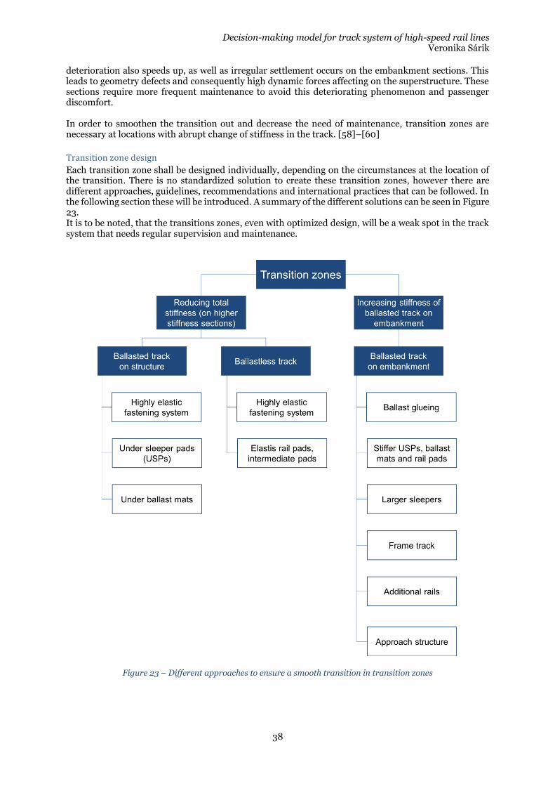
Decision-making model for track system of high-speed rail lines Veronika Sárik
38
deterioration also speeds up, as well as irregular settlement occurs on the embankment sections. This leads to geometry defects and consequently high dynamic forces affecting on the superstructure. These sections require more frequent maintenance to avoid this deteriorating phenomenon and passenger discomfort. In order to smoothen the transition out and decrease the need of maintenance, transition zones are necessary at locations with abrupt change of stiffness in the track. [58]–[60]
Transition zone design
Each transition zone shall be designed individually, depending on the circumstances at the location of the transition. There is no standardized solution to create these transition zones, however there are different approaches, guidelines, recommendations and international practices that can be followed. In the following section these will be introduced. A summary of the different solutions can be seen in Figure 23. It is to be noted, that the transitions zones, even with optimized design, will be a weak spot in the track system that needs regular supervision and maintenance.
Figure 23 – Different approaches to ensure a smooth transition in transition zones
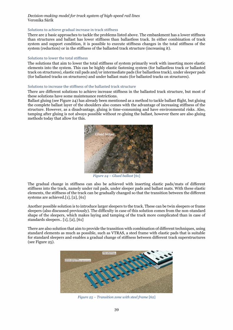
Decision-making model for track system of high-speed rail lines Veronika Sárik
39
Solutions to achieve gradual increase in track stiffness
There are 2 basic approaches to tackle the problems listed above. The embankment has a lower stiffness than structures and ballast has lower stiffness than ballastless track. In either combination of track system and support condition, it is possible to execute stiffness changes in the total stiffness of the system (reduction) or in the stiffness of the ballasted track structure (increasing it).
Solutions to lower the total stiffness
The solutions that aim to lower the total stiffness of system primarily work with inserting more elastic elements into the system. This can be highly elastic fastening system (for ballastless track or ballasted track on structures), elastic rail pads and/or intermediate pads (for ballastless track), under sleeper pads (for ballasted tracks on structures) and under ballast mats (for ballasted tracks on structures).
Solutions to increase the stiffness of the ballasted track structure
There are different solutions to achieve increase stiffness in the ballasted track structure, but most of these solutions have some maintenance restrictions. Ballast gluing (see Figure 24) has already been mentioned as a method to tackle ballast flight, but gluing the complete ballast layer of the shoulders also comes with the advantage of increasing stiffness of the structure. However, as a disadvantage, gluing is time-consuming and have environmental risks. Also, tamping after gluing is not always possible without re-gluing the ballast, however there are also gluing methods today that allow for this.
Figure 24 – Glued ballast [61]
The gradual change in stiffness can also be achieved with inserting elastic pads/mats of different stiffness into the track, namely under rail pads, under sleeper pads and ballast mats. With these elastic elements, the stiffness of the track can be gradually changed so that the transition between the different systems are achieved.[1], [2], [61] Another possible solution is to introduce larger sleepers to the track. These can be twin sleepers or frame sleepers (also discussed previously). The difficulty in case of this solution comes from the non-standard shape of the sleepers, which makes laying and tamping of the track more complicated than in case of standards sleepers.. [1], [2], [61] There are also solution that aim to provide the transition with combination of different techniques, using standard elements as much as possible, such as VTRAS, a steel frame with elastic pads that is suitable for standard sleepers and enables a gradual change of stiffness between different track superstructures (see Figure 25).
Figure 25 – Transition zone with steel frame [62]
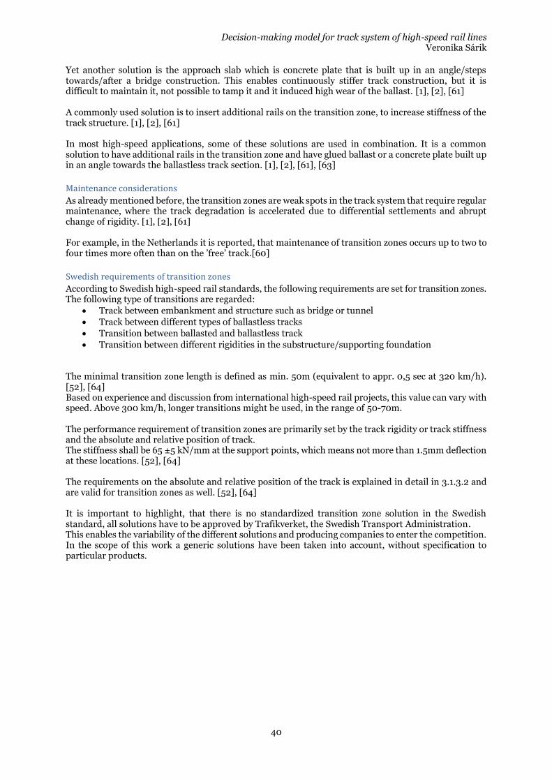
Decision-making model for track system of high-speed rail lines Veronika Sárik
40
Yet another solution is the approach slab which is concrete plate that is built up in an angle/steps towards/after a bridge construction. This enables continuously stiffer track construction, but it is difficult to maintain it, not possible to tamp it and it induced high wear of the ballast. [1], [2], [61] A commonly used solution is to insert additional rails on the transition zone, to increase stiffness of the track structure. [1], [2], [61] In most high-speed applications, some of these solutions are used in combination. It is a common solution to have additional rails in the transition zone and have glued ballast or a concrete plate built up in an angle towards the ballastless track section. [1], [2], [61], [63]
Maintenance considerations
As already mentioned before, the transition zones are weak spots in the track system that require regular maintenance, where the track degradation is accelerated due to differential settlements and abrupt change of rigidity. [1], [2], [61] For example, in the Netherlands it is reported, that maintenance of transition zones occurs up to two to four times more often than on the ’free’ track.[60]
Swedish requirements of transition zones
According to Swedish high-speed rail standards, the following requirements are set for transition zones. The following type of transitions are regarded:
• Track between embankment and structure such as bridge or tunnel
• Track between different types of ballastless tracks
• Transition between ballasted and ballastless track
• Transition between different rigidities in the substructure/supporting foundation
The minimal transition zone length is defined as min. 50m (equivalent to appr. 0,5 sec at 320 km/h). [52], [64] Based on experience and discussion from international high-speed rail projects, this value can vary with speed. Above 300 km/h, longer transitions might be used, in the range of 50-70m. The performance requirement of transition zones are primarily set by the track rigidity or track stiffness and the absolute and relative position of track. The stiffness shall be 65 ±5 kN/mm at the support points, which means not more than 1.5mm deflection at these locations. [52], [64] The requirements on the absolute and relative position of the track is explained in detail in 3.1.3.2 and are valid for transition zones as well. [52], [64] It is important to highlight, that there is no standardized transition zone solution in the Swedish standard, all solutions have to be approved by Trafikverket, the Swedish Transport Administration. This enables the variability of the different solutions and producing companies to enter the competition. In the scope of this work a generic solutions have been taken into account, without specification to particular products.
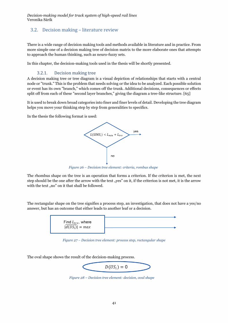
Decision-making model for track system of high-speed rail lines Veronika Sárik
41
3.2. Decision making – literature review
There is a wide range of decision making tools and methods available in literature and in practice. From
more simple one of a decision making tree of decision matrix to the more elaborate ones that attempts
to approach the human thinking, such as neuro-fuzzy sets.
In this chapter, the decision-making tools used in the thesis will be shortly presented.
3.2.1. Decision making tree A decision making tree or tree diagram is a visual depiction of relationships that starts with a central
node or "trunk." This is the problem that needs solving or the idea to be analyzed. Each possible solution
or event has its own "branch," which comes off the trunk. Additional decisions, consequences or effects
split off from each of these "second layer branches," giving the diagram a tree-like structure. [65]
It is used to break down broad categories into finer and finer levels of detail. Developing the tree diagram
helps you move your thinking step by step from generalities to specifics.
In the thesis the following format is used:
The rhombus shape on the tree is an operation that forms a criterion. If the criterion is met, the next
step should be the one after the arrow with the text „yes” on it, if the criterion is not met, it is the arrow
with the text „no” on it that shall be followed.
The rectangular shape on the tree signifies a process step, an investigation, that does not have a yes/no
answer, but has an outcome that either leads to another leaf or a decision.
Figure 27 – Decision tree element: process step, rectangular shape
The oval shape shows the result of the decision-making process.
Figure 26 – Decision tree element: criteria, rombus shape
Figure 28 – Decision tree element: decision, oval shape
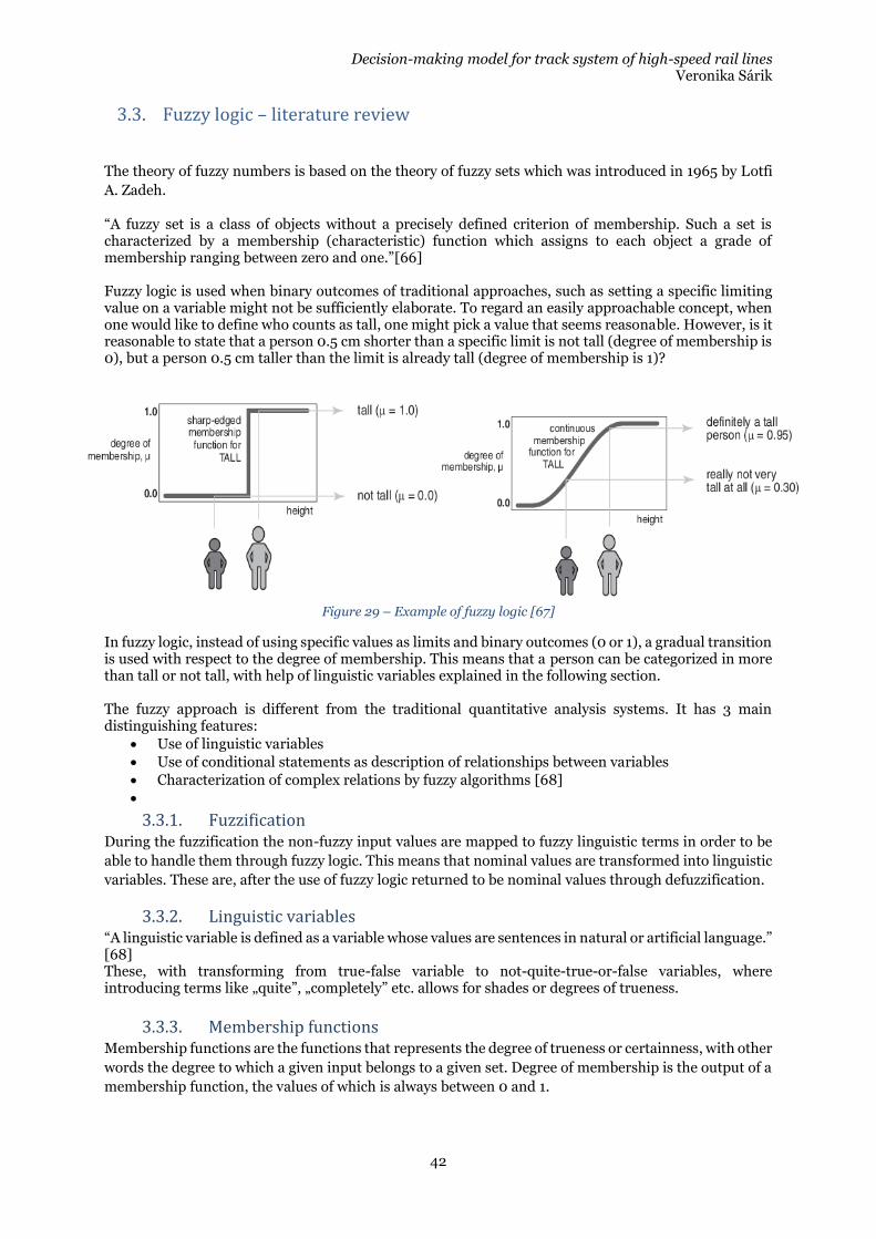
Decision-making model for track system of high-speed rail lines Veronika Sárik
42
3.3. Fuzzy logic – literature review
The theory of fuzzy numbers is based on the theory of fuzzy sets which was introduced in 1965 by Lotfi
A. Zadeh.
“A fuzzy set is a class of objects without a precisely defined criterion of membership. Such a set is characterized by a membership (characteristic) function which assigns to each object a grade of membership ranging between zero and one.”[66] Fuzzy logic is used when binary outcomes of traditional approaches, such as setting a specific limiting value on a variable might not be sufficiently elaborate. To regard an easily approachable concept, when one would like to define who counts as tall, one might pick a value that seems reasonable. However, is it reasonable to state that a person 0.5 cm shorter than a specific limit is not tall (degree of membership is 0), but a person 0.5 cm taller than the limit is already tall (degree of membership is 1)?
Figure 29 – Example of fuzzy logic [67]
In fuzzy logic, instead of using specific values as limits and binary outcomes (0 or 1), a gradual transition is used with respect to the degree of membership. This means that a person can be categorized in more than tall or not tall, with help of linguistic variables explained in the following section. The fuzzy approach is different from the traditional quantitative analysis systems. It has 3 main distinguishing features:
• Use of linguistic variables
• Use of conditional statements as description of relationships between variables
• Characterization of complex relations by fuzzy algorithms [68]
•
3.3.1. Fuzzification During the fuzzification the non-fuzzy input values are mapped to fuzzy linguistic terms in order to be
able to handle them through fuzzy logic. This means that nominal values are transformed into linguistic
variables. These are, after the use of fuzzy logic returned to be nominal values through defuzzification.
3.3.2. Linguistic variables “A linguistic variable is defined as a variable whose values are sentences in natural or artificial language.” [68] These, with transforming from true-false variable to not-quite-true-or-false variables, where introducing terms like „quite”, „completely” etc. allows for shades or degrees of trueness.
3.3.3. Membership functions Membership functions are the functions that represents the degree of trueness or certainness, with other
words the degree to which a given input belongs to a given set. Degree of membership is the output of a
membership function, the values of which is always between 0 and 1.
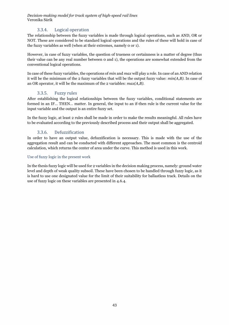
Decision-making model for track system of high-speed rail lines Veronika Sárik
43
3.3.4. Logical operation The relationship between the fuzzy variables is made through logical operations, such as AND, OR or
NOT. These are considered to be standard logical operations and the rules of these will hold in case of
the fuzzy variables as well (when at their extremes, namely 0 or 1).
However, in case of fuzzy variables, the question of trueness or certainness is a matter of degree (thus
their value can be any real number between 0 and 1), the operations are somewhat extended from the
conventional logical operations.
In case of these fuzzy variables, the operations of min and max will play a role. In case of an AND relation
it will be the minimum of the 2 fuzzy variables that will be the output fuzzy value: min(A,B). In case of
an OR operator, it will be the maximum of the 2 variables: max(A,B).
3.3.5. Fuzzy rules After establishing the logical relationships between the fuzzy variables, conditional statements are
formed in an IF… THEN… matter. In general, the input to an if-then rule is the current value for the
input variable and the output is an entire fuzzy set.
In the fuzzy logic, at least 2 rules shall be made in order to make the results meaningful. All rules have
to be evaluated according to the previously described process and their output shall be aggregated.
3.3.6. Defuzzification In order to have an output value, defuzzification is necessary. This is made with the use of the
aggregation result and can be conducted with different approaches. The most common is the centroid
calculation, which returns the center of area under the curve. This method is used in this work.
Use of fuzzy logic in the present work
In the thesis fuzzy logic will be used for 2 variables in the decision making process, namely: ground water
level and depth of weak quality subsoil. These have been chosen to be handled through fuzzy logic, as it
is hard to use one designated value for the limit of their suitability for ballastless track. Details on the
use of fuzzy logic on these variables are presented in 4.6.4.
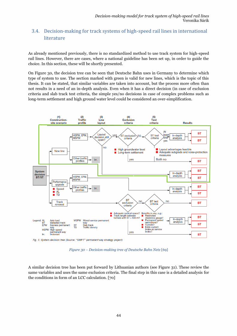
Decision-making model for track system of high-speed rail lines Veronika Sárik
44
3.4. Decision-making for track systems of high-speed rail lines in international
literature
As already mentioned previously, there is no standardized method to use track system for high-speed
rail lines. However, there are cases, where a national guideline has been set up, in order to guide the
choice. In this section, these will be shortly presented.
On Figure 30, the decision tree can be seen that Deutsche Bahn uses in Germany to determine which
type of system to use. The section marked with green is valid for new lines, which is the topic of this
thesis. It can be stated, that similar variables are taken into account, but the process more often than
not results in a need of an in-depth analysis. Even when it has a direct decision (in case of exclusion
criteria and slab track test criteria, the simple yes/no decisions in case of complex problems such as
long-term settlement and high ground water level could be considered an over-simplification.
Figure 30 – Decision-making tree of Deutsche Bahn Netz [69]
A similar decision tree has been put forward by Lithuanian authors (see Figure 31). These review the
same variables and uses the same exclusion criteria. The final step in this case is a detailed analysis for
the conditions in form of an LCC calculation. [70]
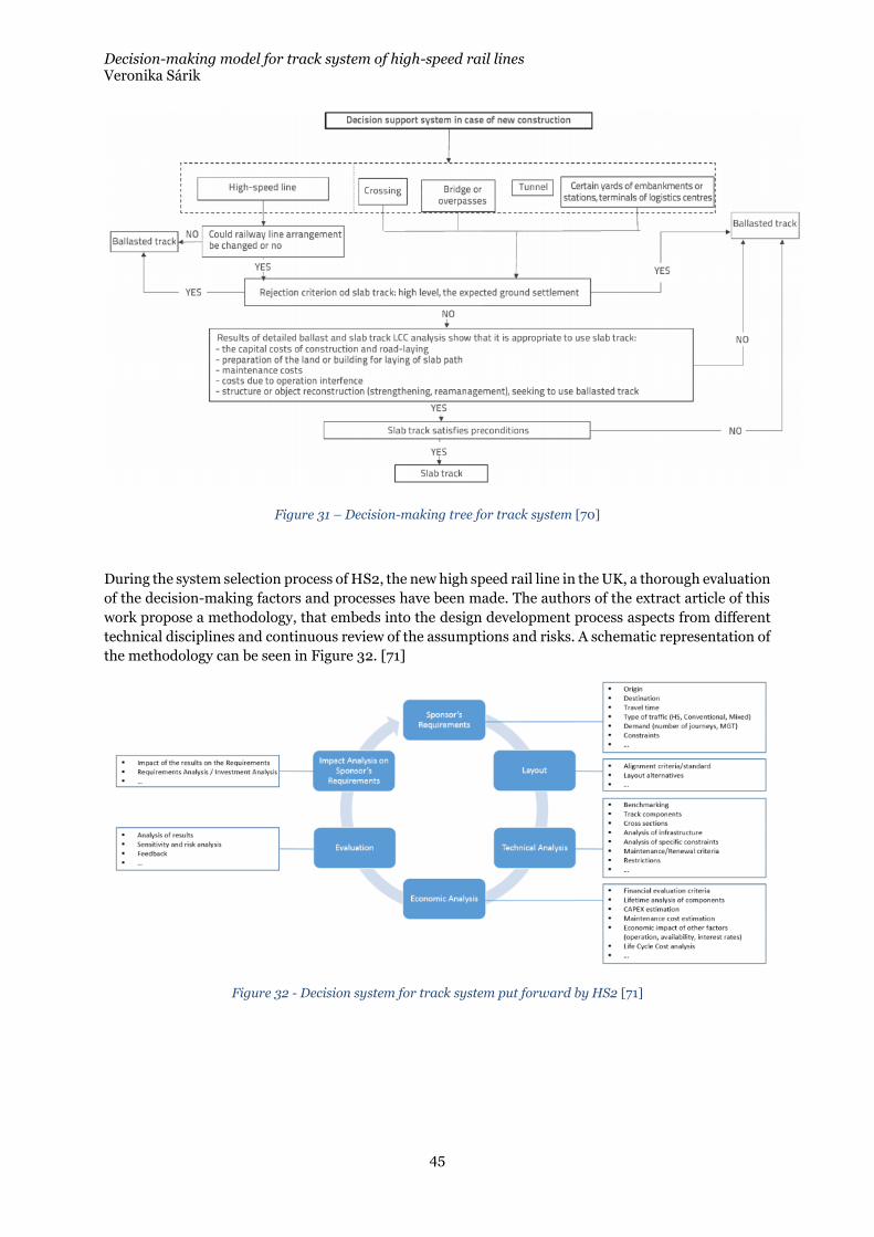
Decision-making model for track system of high-speed rail lines Veronika Sárik
45
Figure 31 – Decision-making tree for track system [70]
During the system selection process of HS2, the new high speed rail line in the UK, a thorough evaluation
of the decision-making factors and processes have been made. The authors of the extract article of this
work propose a methodology, that embeds into the design development process aspects from different
technical disciplines and continuous review of the assumptions and risks. A schematic representation of
the methodology can be seen in Figure 32. [71]
Figure 32 - Decision system for track system put forward by HS2 [71]
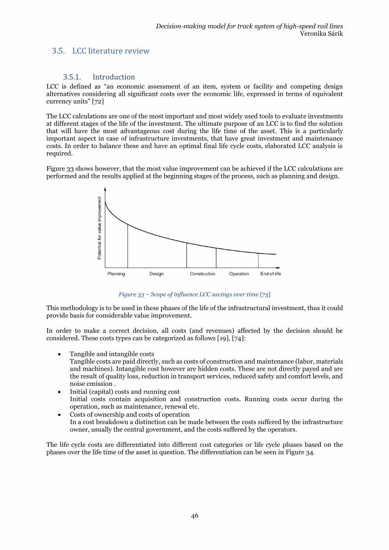
Decision-making model for track system of high-speed rail lines Veronika Sárik
46
3.5. LCC literature review
3.5.1. Introduction LCC is defined as “an economic assessment of an item, system or facility and competing design alternatives considering all significant costs over the economic life, expressed in terms of equivalent currency units” [72] The LCC calculations are one of the most important and most widely used tools to evaluate investments at different stages of the life of the investment. The ultimate purpose of an LCC is to find the solution that will have the most advantageous cost during the life time of the asset. This is a particularly important aspect in case of infrastructure investments, that have great investment and maintenance costs. In order to balance these and have an optimal final life cycle costs, elaborated LCC analysis is required.
Figure 33 shows however, that the most value improvement can be achieved if the LCC calculations are performed and the results applied at the beginning stages of the process, such as planning and design.
Figure 33 – Scope of influence LCC savings over time [73]
This methodology is to be used in these phases of the life of the infrastructural investment, thus it could provide basis for considerable value improvement.
In order to make a correct decision, all costs (and revenues) affected by the decision should be considered. These costs types can be categorized as follows [19], [74]:
• Tangible and intangible costs Tangible costs are paid directly, such as costs of construction and maintenance (labor, materials and machines). Intangible cost however are hidden costs. These are not directly payed and are the result of quality loss, reduction in transport services, reduced safety and comfort levels, and noise emission .
• Initial (capital) costs and running cost Initial costs contain acquisition and construction costs. Running costs occur during the operation, such as maintenance, renewal etc.
• Costs of ownership and costs of operation In a cost breakdown a distinction can be made between the costs suffered by the infrastructure owner, usually the central government, and the costs suffered by the operators.
The life cycle costs are differentiated into different cost categories or life cycle phases based on the phases over the life time of the asset in question. The differentiation can be seen in Figure 34.
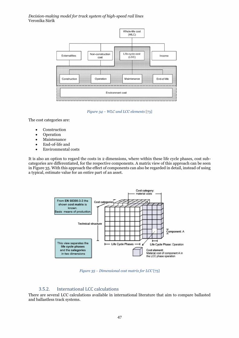
Decision-making model for track system of high-speed rail lines Veronika Sárik
47
Figure 34 – WLC and LCC elements [73]
The cost categories are:
• Construction
• Operation
• Maintenance
• End-of-life and
• Environmental costs
It is also an option to regard the costs in 2 dimensions, where within these life cycle phases, cost sub-categories are differentiated, for the respective components. A matrix view of this approach can be seen in Figure 35. With this approach the effect of components can also be regarded in detail, instead of using a typical, estimate value for an entire part of an asset.
Figure 35 – Dimensional cost matrix for LCC [75]
3.5.2. International LCC calculations There are several LCC calculations available in international literature that aim to compare ballasted and ballastless track systems.
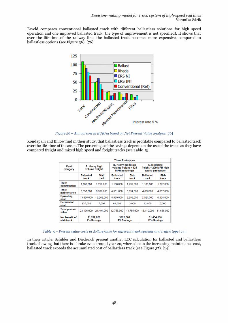
Decision-making model for track system of high-speed rail lines Veronika Sárik
48
Esveld compares conventional ballasted track with different ballastless solutions for high speed operation and one improved ballasted track (the type of improvement is not specified). It shows that over the life-time of the railway line, the ballasted track becomes more expensive, compared to ballastless options (see Figure 36). [76]
Figure 36 – Annual cost in EUR/m based on Net Present Value analysis [76]
Kondapalli and Billow find in their study, that ballastless track is profitable compared to ballasted track over the life-time of the asset. The percentage of the savings depend on the use of the track, as they have compared freight and mixed high speed and freight tracks (see Table 5).
Table 5 – Present value costs in dollars/mile for different track systems and traffic type [77]
In their article, Schilder and Diederich present another LCC calculation for ballasted and ballastless track, showing that there is a brake even around year 20, where due to the increasing maintenance cost, ballasted track exceeds the accumulated cost of ballastless track (see Figure 37). [14]
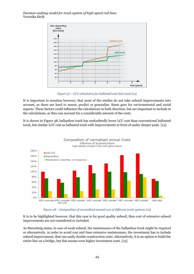
Decision-making model for track system of high-speed rail lines Veronika Sárik
49
Figure 37 – LCC calculation for ballasted and slab track [14]
It is important to mention however, that most of the studies do not take subsoil improvements into
account, as these are hard to assess, predict or generalize. Same goes for environmental and social
aspects. These factors could influence the calculations in both direction, but are important to include in
the calculations, as they can account for a considerable amount of the costs.
It is shown in Figure 38, ballastless track has undoubtedly lower LCC cost than conventional ballasted
track, but similar LCC cost as ballasted track with improvements in form of under sleeper pads. [13]
Figure 38 – Composition of normalized annual cost of different track systems [13]
It is to be highlighted however, that this case is for good quality subsoil, thus cost of extensive subsoil
improvements are not considered or included.
As Marschnig states, in case of weak subsoil, the maintenance of the ballastless track might be required
or alternatively, in order to avoid cost and time extensive maintenance, the investment has to include
subsoil improvement, that can easily double construction costs. Alternatively, it is an option to build the
entire line on a bridge, but this means even higher investment costs. [13]
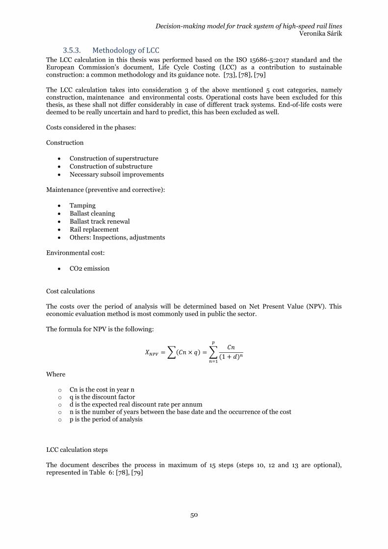
Decision-making model for track system of high-speed rail lines Veronika Sárik
50
3.5.3. Methodology of LCC The LCC calculation in this thesis was performed based on the ISO 15686-5:2017 standard and the European Commission’s document, Life Cycle Costing (LCC) as a contribution to sustainable construction: a common methodology and its guidance note. [73], [78], [79]
The LCC calculation takes into consideration 3 of the above mentioned 5 cost categories, namely construction, maintenance and environmental costs. Operational costs have been excluded for this thesis, as these shall not differ considerably in case of different track systems. End-of-life costs were deemed to be really uncertain and hard to predict, this has been excluded as well.
Costs considered in the phases:
Construction
• Construction of superstructure
• Construction of substructure
• Necessary subsoil improvements
Maintenance (preventive and corrective):
• Tamping
• Ballast cleaning
• Ballast track renewal
• Rail replacement
• Others: Inspections, adjustments
Environmental cost:
• CO2 emission
Cost calculations
The costs over the period of analysis will be determined based on Net Present Value (NPV). This economic evaluation method is most commonly used in public the sector.
The formula for NPV is the following:
𝑋𝑁𝑃𝑉 =∑(𝐶𝑛 × 𝑞) = ∑𝐶𝑛
(1 + 𝑑)𝑛
𝑝
𝑛=1
Where
o Cn is the cost in year n o q is the discount factor o d is the expected real discount rate per annum o n is the number of years between the base date and the occurrence of the cost o p is the period of analysis
LCC calculation steps
The document describes the process in maximum of 15 steps (steps 10, 12 and 13 are optional), represented in Table 6: [78], [79]
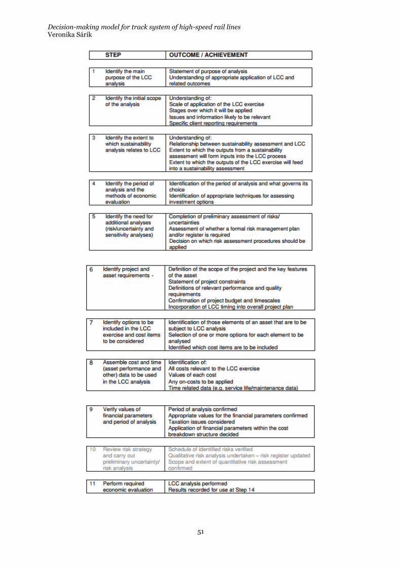
Decision-making model for track system of high-speed rail lines Veronika Sárik
51

Decision-making model for track system of high-speed rail lines Veronika Sárik
52
Table 6 – LCC process steps [78], [79]
Decision-making model for track system of high-speed rail lines Veronika Sárik
53
4. Decision making model
In the current section, the decision-making model that has been proposed by the author is presented. It
is important to highlight that the thesis aims to create and describe a methodology and all input
parameters are subject to discussion and depend on the country conditions and requirements. The
values described in the following are based on the Swedish conditions and discussions with experts.
In the present section the LCC calculation parameters and input data is excluded, it is explained in detail
in the 4.8.
4.1. Model variables The model variables selected for the decision making model are the following.
4.1.1. Global level:
4.1.1.1. Completed design
The completeness of the design is to be taken into account as in case of ballastless track there are
geometrical advantages that usually cannot be implemented in case of ballasted tracks. It is therefore
important to evaluate if the design is completed and if so, the alignment is suitable for both systems.
4.1.1.2. Suitability for both systems
In case the design is completed and not to be adjusted anymore, there is still the possibility that the
design did not use values that exceed the limits of the ballasted track (within the allowed range for the
ballastless track), thus the alignment can accommodate both type of systems.
4.1.1.3. High speed
As discussed previously, it is mostly in case of high speed operation, that the use of ballastless track is
considered, as in this type of operation, the availability requirement is high, the maintenance window is
short, thus despite of the higher initial construction cost, it might be profitable to build this system.
4.1.2. Local level:
4.1.2.1. Ground water level
As previously discussed, the ground water level is one of the exclusion criteria for ballastless track (if no
measures against is is considered). If the ground water level exceeds a certain depth (determined as
input data, see in detail in 4.6.4.3), the suitability of ballastless track becomes questionable.
4.1.2.2. Depth of weak subsoil
The depth of the weak quality subsoil is an indicator for suitability of different technologies. There is a
certain depth of weak subsoil where relatively easy and low-cost procedures are not sufficient and
extensive ground improvement is required.
As previously discussed, the quality of the subsoil is one of the exclusion criteria for ballastless track (if
no measures against it is considered). If the subsoil is prone to settle, it endangers the strict
requirements on settlements and endangers the maintenance-free condition of the ballastless track
structures.
4.1.2.3. Structure
In this thesis, based on the international literature and consultation with experts, it is assumed that on
structures such as bridges and tunnels, it is more advantageous to use ballastless track.
Decision-making model for track system of high-speed rail lines Veronika Sárik
54
4.2. Input data Within input data 2 categories are differentiated. The first group will be the input data for the variables.
These are the values coming from the project itself and used to populate the decision making model. The
second group is the input data for model parameters. These are the country/company specific
preferences that enables flexibility of the model to be fine-tuned.
4.2.1. Input data for the variables The data on the above-mentioned input parameters are used for evaluation. These data is gathered from
the specification and design of the project, moreover from the geotechnical investigations. The frequency
of the geotechnical investigation can also determine further input data (model parameters) described in
the following section.
4.2.1.1. Ground water level
The input data for the ground water level shall be obtained through geotechnical investigations. Ground
water level in this work is measured from the formation level.
4.2.1.2. Subsoil conditions
The input data for the subsoil condition shall be obtained through geotechnical investigations. Depth of
weak subsoil strata is measured from the subsoil level in a given cross-section (natural ground level in
case of an embankment and formation in case of a cut).
4.2.2. Model parameters The model parameters affecting the model are the following:
4.2.2.1. Length of unit section
In case of the alternating systems option, a unit length is to be selected, in order to be able to evaluate
the suitability of the systems on a section basis. This is important as the sections are selected based on
the section based suitability.
4.2.2.2. Limit of subsoil quality
The quality of the subsoil is to be selected in order to determine what is the type of subsoil that is
regarded as unsuitable for use of ballastless track without replacement, improvement or reinforcement.
4.2.2.3. Limit of subsoil depth
The depth of the above mentioned weak subsoil quality is to be determined in order to evaluate from
what depth it is not suitable to construct ballastless track without extensive ground improvement.
Instead of a specific value, a membership function to be determined if the fuzzy logic is to be used (See
in detail 4.6.4.3).
4.2.2.4. Limit of ground water level
The ground water level is to be determined in order to evaluate from what level it is not suitable to
construct ballastless. Instead of a specific value, a membership function to be determined if the fuzzy
logic is to be used (See in detail 4.6.4.3).
All of these input data can be adjusted based on the requirements and preferences of the interested
party.
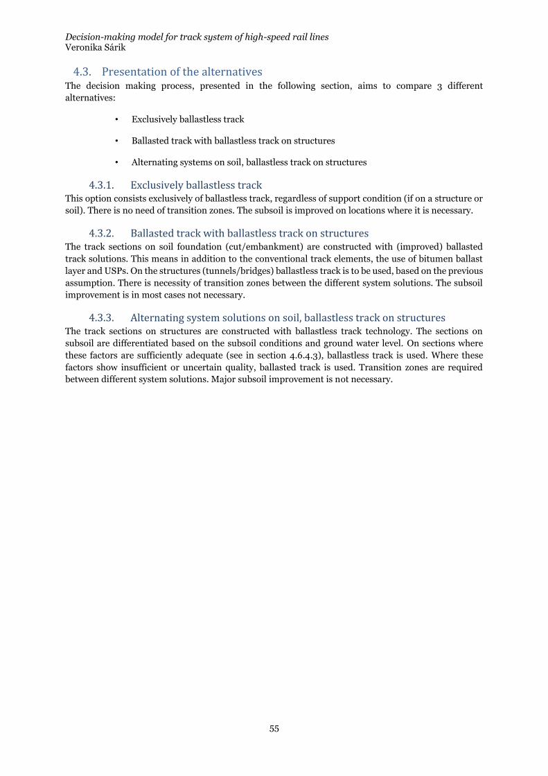
Decision-making model for track system of high-speed rail lines Veronika Sárik
55
4.3. Presentation of the alternatives The decision making process, presented in the following section, aims to compare 3 different
alternatives:
• Exclusively ballastless track
• Ballasted track with ballastless track on structures
• Alternating systems on soil, ballastless track on structures
4.3.1. Exclusively ballastless track This option consists exclusively of ballastless track, regardless of support condition (if on a structure or
soil). There is no need of transition zones. The subsoil is improved on locations where it is necessary.
4.3.2. Ballasted track with ballastless track on structures The track sections on soil foundation (cut/embankment) are constructed with (improved) ballasted
track solutions. This means in addition to the conventional track elements, the use of bitumen ballast
layer and USPs. On the structures (tunnels/bridges) ballastless track is to be used, based on the previous
assumption. There is necessity of transition zones between the different system solutions. The subsoil
improvement is in most cases not necessary.
4.3.3. Alternating system solutions on soil, ballastless track on structures The track sections on structures are constructed with ballastless track technology. The sections on
subsoil are differentiated based on the subsoil conditions and ground water level. On sections where
these factors are sufficiently adequate (see in section 4.6.4.3), ballastless track is used. Where these
factors show insufficient or uncertain quality, ballasted track is used. Transition zones are required
between different system solutions. Major subsoil improvement is not necessary.
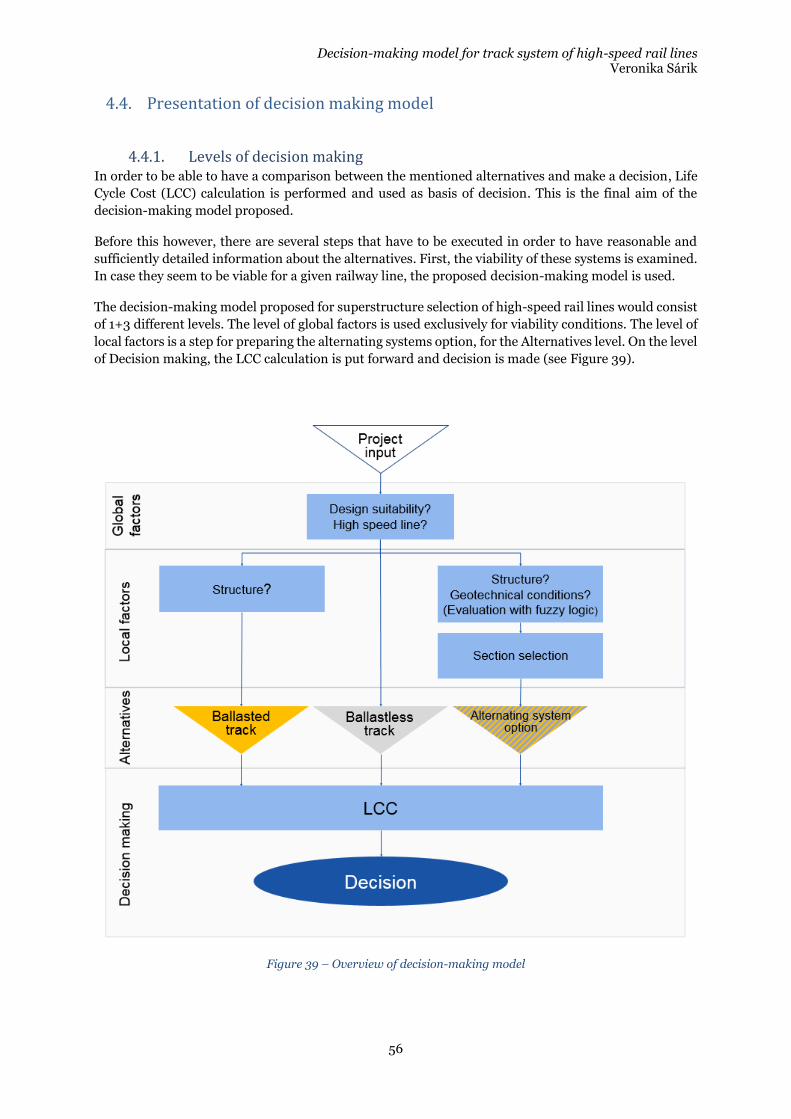
Decision-making model for track system of high-speed rail lines Veronika Sárik
56
4.4. Presentation of decision making model
4.4.1. Levels of decision making In order to be able to have a comparison between the mentioned alternatives and make a decision, Life
Cycle Cost (LCC) calculation is performed and used as basis of decision. This is the final aim of the
decision-making model proposed.
Before this however, there are several steps that have to be executed in order to have reasonable and
sufficiently detailed information about the alternatives. First, the viability of these systems is examined.
In case they seem to be viable for a given railway line, the proposed decision-making model is used.
The decision-making model proposed for superstructure selection of high-speed rail lines would consist
of 1+3 different levels. The level of global factors is used exclusively for viability conditions. The level of
local factors is a step for preparing the alternating systems option, for the Alternatives level. On the level
of Decision making, the LCC calculation is put forward and decision is made (see Figure 39).
Figure 39 – Overview of decision-making model
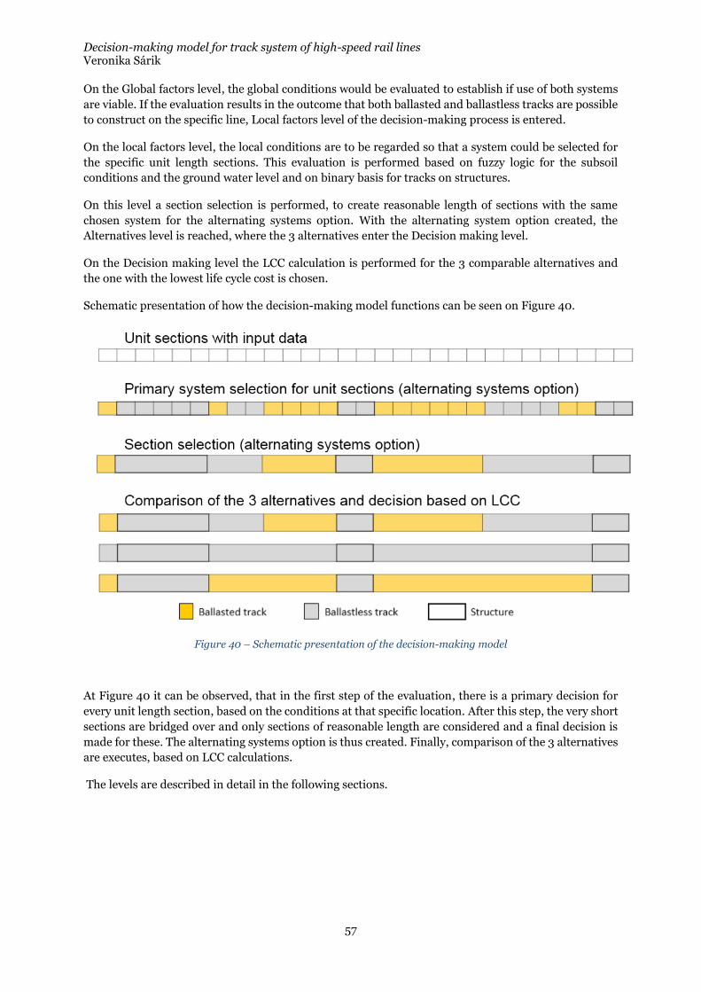
Decision-making model for track system of high-speed rail lines Veronika Sárik
57
On the Global factors level, the global conditions would be evaluated to establish if use of both systems
are viable. If the evaluation results in the outcome that both ballasted and ballastless tracks are possible
to construct on the specific line, Local factors level of the decision-making process is entered.
On the local factors level, the local conditions are to be regarded so that a system could be selected for
the specific unit length sections. This evaluation is performed based on fuzzy logic for the subsoil
conditions and the ground water level and on binary basis for tracks on structures.
On this level a section selection is performed, to create reasonable length of sections with the same
chosen system for the alternating systems option. With the alternating system option created, the
Alternatives level is reached, where the 3 alternatives enter the Decision making level.
On the Decision making level the LCC calculation is performed for the 3 comparable alternatives and
the one with the lowest life cycle cost is chosen.
Schematic presentation of how the decision-making model functions can be seen on Figure 40.
Figure 40 – Schematic presentation of the decision-making model
At Figure 40 it can be observed, that in the first step of the evaluation, there is a primary decision for
every unit length section, based on the conditions at that specific location. After this step, the very short
sections are bridged over and only sections of reasonable length are considered and a final decision is
made for these. The alternating systems option is thus created. Finally, comparison of the 3 alternatives
are executes, based on LCC calculations.
The levels are described in detail in the following sections.
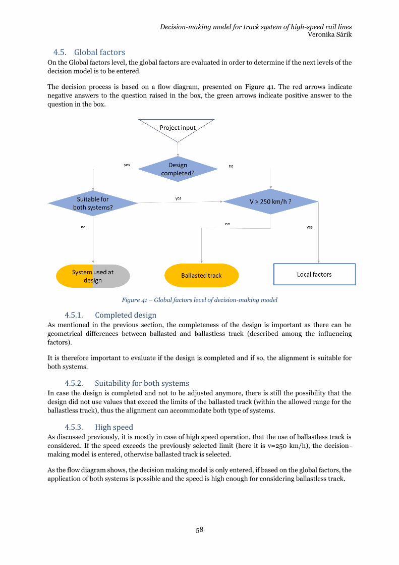
Decision-making model for track system of high-speed rail lines Veronika Sárik
58
4.5. Global factors On the Global factors level, the global factors are evaluated in order to determine if the next levels of the
decision model is to be entered.
The decision process is based on a flow diagram, presented on Figure 41. The red arrows indicate
negative answers to the question raised in the box, the green arrows indicate positive answer to the
question in the box.
Figure 41 – Global factors level of decision-making model
4.5.1. Completed design As mentioned in the previous section, the completeness of the design is important as there can be
geometrical differences between ballasted and ballastless track (described among the influencing
factors).
It is therefore important to evaluate if the design is completed and if so, the alignment is suitable for
both systems.
4.5.2. Suitability for both systems In case the design is completed and not to be adjusted anymore, there is still the possibility that the
design did not use values that exceed the limits of the ballasted track (within the allowed range for the
ballastless track), thus the alignment can accommodate both type of systems.
4.5.3. High speed As discussed previously, it is mostly in case of high speed operation, that the use of ballastless track is
considered. If the speed exceeds the previously selected limit (here it is v=250 km/h), the decision-
making model is entered, otherwise ballasted track is selected.
As the flow diagram shows, the decision making model is only entered, if based on the global factors, the
application of both systems is possible and the speed is high enough for considering ballastless track.
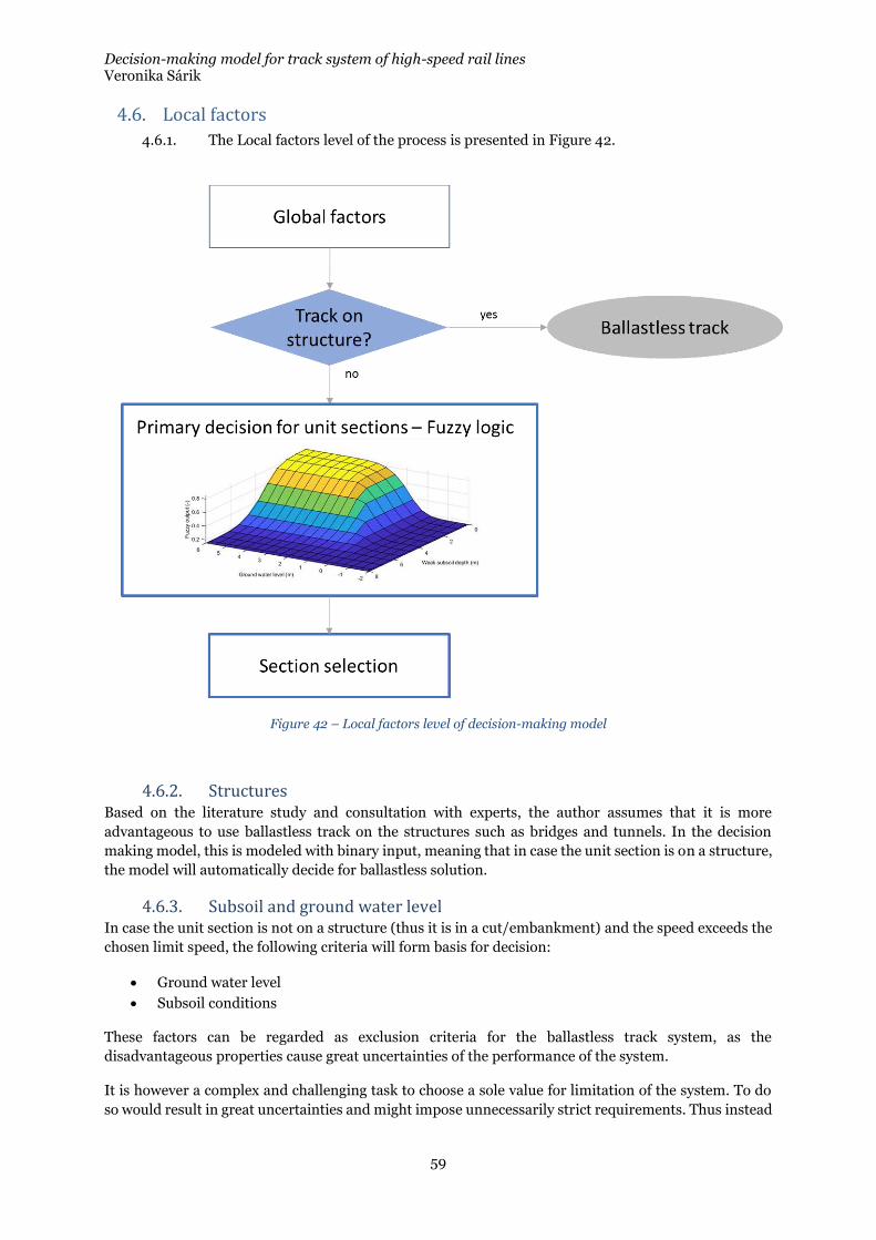
Decision-making model for track system of high-speed rail lines Veronika Sárik
59
4.6. Local factors
4.6.1. The Local factors level of the process is presented in Figure 42.
Figure 42 – Local factors level of decision-making model
4.6.2. Structures Based on the literature study and consultation with experts, the author assumes that it is more
advantageous to use ballastless track on the structures such as bridges and tunnels. In the decision
making model, this is modeled with binary input, meaning that in case the unit section is on a structure,
the model will automatically decide for ballastless solution.
4.6.3. Subsoil and ground water level In case the unit section is not on a structure (thus it is in a cut/embankment) and the speed exceeds the
chosen limit speed, the following criteria will form basis for decision:
• Ground water level
• Subsoil conditions
These factors can be regarded as exclusion criteria for the ballastless track system, as the
disadvantageous properties cause great uncertainties of the performance of the system.
It is however a complex and challenging task to choose a sole value for limitation of the system. To do
so would result in great uncertainties and might impose unnecessarily strict requirements. Thus instead
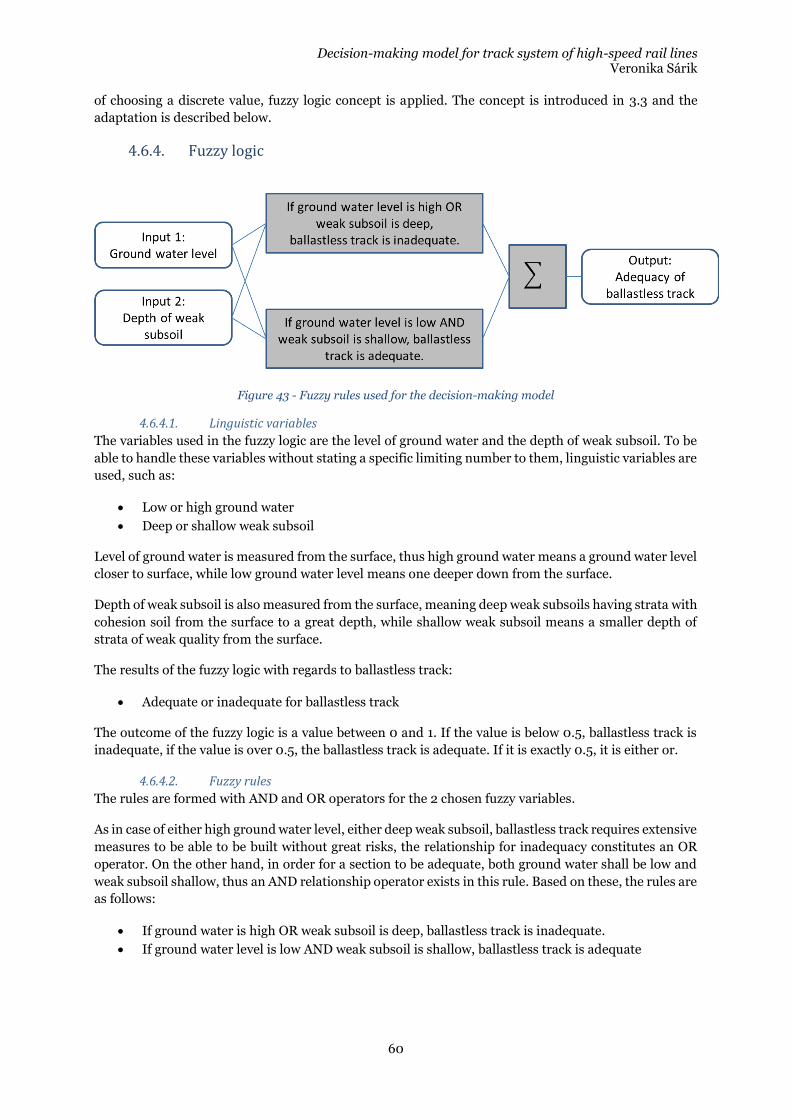
Decision-making model for track system of high-speed rail lines Veronika Sárik
60
of choosing a discrete value, fuzzy logic concept is applied. The concept is introduced in 3.3 and the
adaptation is described below.
4.6.4. Fuzzy logic
Figure 43 - Fuzzy rules used for the decision-making model
4.6.4.1. Linguistic variables
The variables used in the fuzzy logic are the level of ground water and the depth of weak subsoil. To be
able to handle these variables without stating a specific limiting number to them, linguistic variables are
used, such as:
• Low or high ground water
• Deep or shallow weak subsoil
Level of ground water is measured from the surface, thus high ground water means a ground water level
closer to surface, while low ground water level means one deeper down from the surface.
Depth of weak subsoil is also measured from the surface, meaning deep weak subsoils having strata with
cohesion soil from the surface to a great depth, while shallow weak subsoil means a smaller depth of
strata of weak quality from the surface.
The results of the fuzzy logic with regards to ballastless track:
• Adequate or inadequate for ballastless track
The outcome of the fuzzy logic is a value between 0 and 1. If the value is below 0.5, ballastless track is
inadequate, if the value is over 0.5, the ballastless track is adequate. If it is exactly 0.5, it is either or.
4.6.4.2. Fuzzy rules
The rules are formed with AND and OR operators for the 2 chosen fuzzy variables.
As in case of either high ground water level, either deep weak subsoil, ballastless track requires extensive
measures to be able to be built without great risks, the relationship for inadequacy constitutes an OR
operator. On the other hand, in order for a section to be adequate, both ground water shall be low and
weak subsoil shallow, thus an AND relationship operator exists in this rule. Based on these, the rules are
as follows:
• If ground water is high OR weak subsoil is deep, ballastless track is inadequate.
• If ground water level is low AND weak subsoil is shallow, ballastless track is adequate
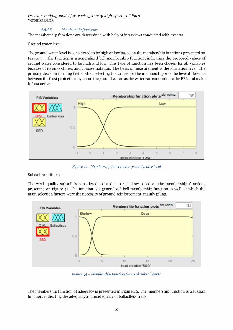
Decision-making model for track system of high-speed rail lines Veronika Sárik
61
4.6.4.3. Membership functions
The membership functions are determined with help of interviews conducted with experts.
Ground water level
The ground water level is considered to be high or low based on the membership functions presented on
Figure 44. The function is a generalized bell membership function, indicating the proposed values of
ground water considered to be high and low. This type of function has been chosen for all variables
because of its smoothness and concise notation. The basis of measurement is the formation level. The
primary decision forming factor when selecting the values for the membership was the level difference
between the frost protection layer and the ground water, as the water can contaminate the FPL and make
it frost active.
Figure 44 - Membership function for ground water level
Subsoil conditions
The weak quality subsoil is considered to be deep or shallow based on the membership functions
presented on Figure 45. The function is a generalized bell membership function as well, at which the
main selection factors were the necessity of ground reinforcement, mainly piling.
Figure 45 – Membership function for weak subsoil depth
The membership function of adequacy is presented in Figure 46. The membership function is Gaussian
function, indicating the adequacy and inadequacy of ballastless track.
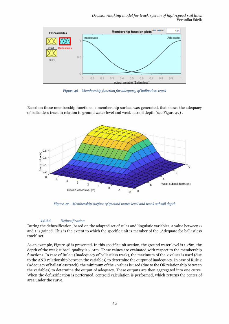
Decision-making model for track system of high-speed rail lines Veronika Sárik
62
Figure 46 – Membership function for adequacy of ballastless track
Based on these membership functions, a membership surface was generated, that shows the adequacy
of ballastless track in relation to ground water level and weak subsoil depth (see Figure 47) .
Figure 47 – Membership surface of ground water level and weak subsoil depth
4.6.4.4. Defuzzification
During the defuzzification, based on the adapted set of rules and linguistic variables, a value between 0
and 1 is gained. This is the extent to which the specific unit is member of the „Adequate for ballastless
track” set.
As an example, Figure 48 is presented. In this specific unit section, the ground water level is 1,28m, the
depth of the weak subsoil quality is 2,61m. These values are evaluated with respect to the membership
functions. In case of Rule 1 (Inadequacy of ballastless track), the maximum of the 2 values is used (due
to the AND relationship between the variables) to determine the output of inadequacy. In case of Rule 2
(Adequacy of ballastless track), the minimum of the 2 values is used (due to the OR relationship between
the variables) to determine the output of adequacy. These outputs are then aggregated into one curve.
When the defuzzification is performed, centroid calculation is performed, which returns the center of
area under the curve.
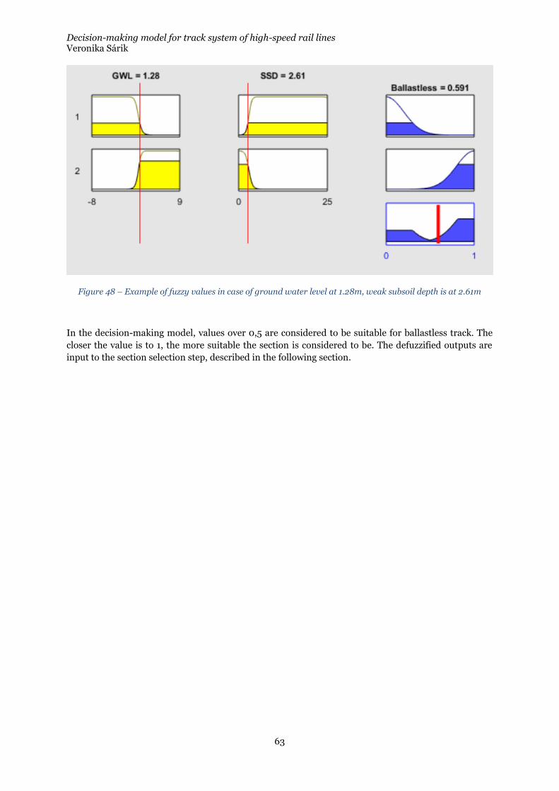
Decision-making model for track system of high-speed rail lines Veronika Sárik
63
Figure 48 – Example of fuzzy values in case of ground water level at 1.28m, weak subsoil depth is at 2.61m
In the decision-making model, values over 0,5 are considered to be suitable for ballastless track. The
closer the value is to 1, the more suitable the section is considered to be. The defuzzified outputs are
input to the section selection step, described in the following section.
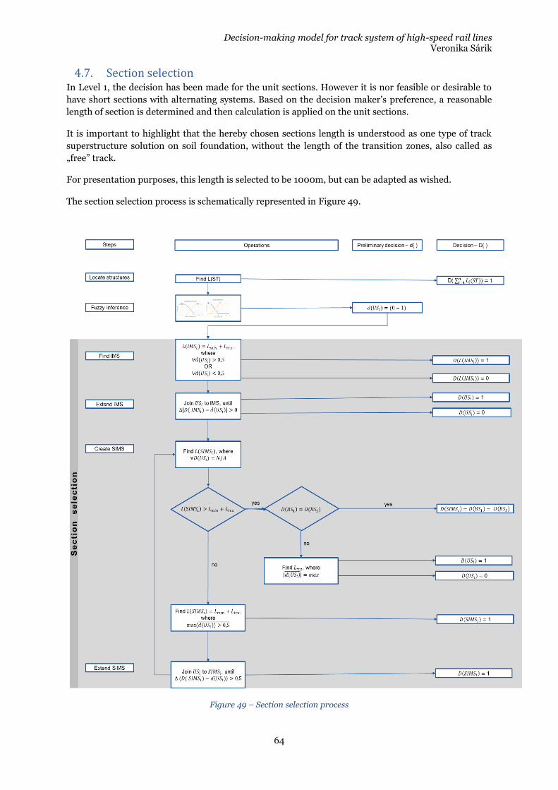
Decision-making model for track system of high-speed rail lines Veronika Sárik
64
4.7. Section selection In Level 1, the decision has been made for the unit sections. However it is nor feasible or desirable to
have short sections with alternating systems. Based on the decision maker’s preference, a reasonable
length of section is determined and then calculation is applied on the unit sections.
It is important to highlight that the hereby chosen sections length is understood as one type of track
superstructure solution on soil foundation, without the length of the transition zones, also called as
„free” track.
For presentation purposes, this length is selected to be 1000m, but can be adapted as wished.
The section selection process is schematically represented in Figure 49.
Figure 49 – Section selection process
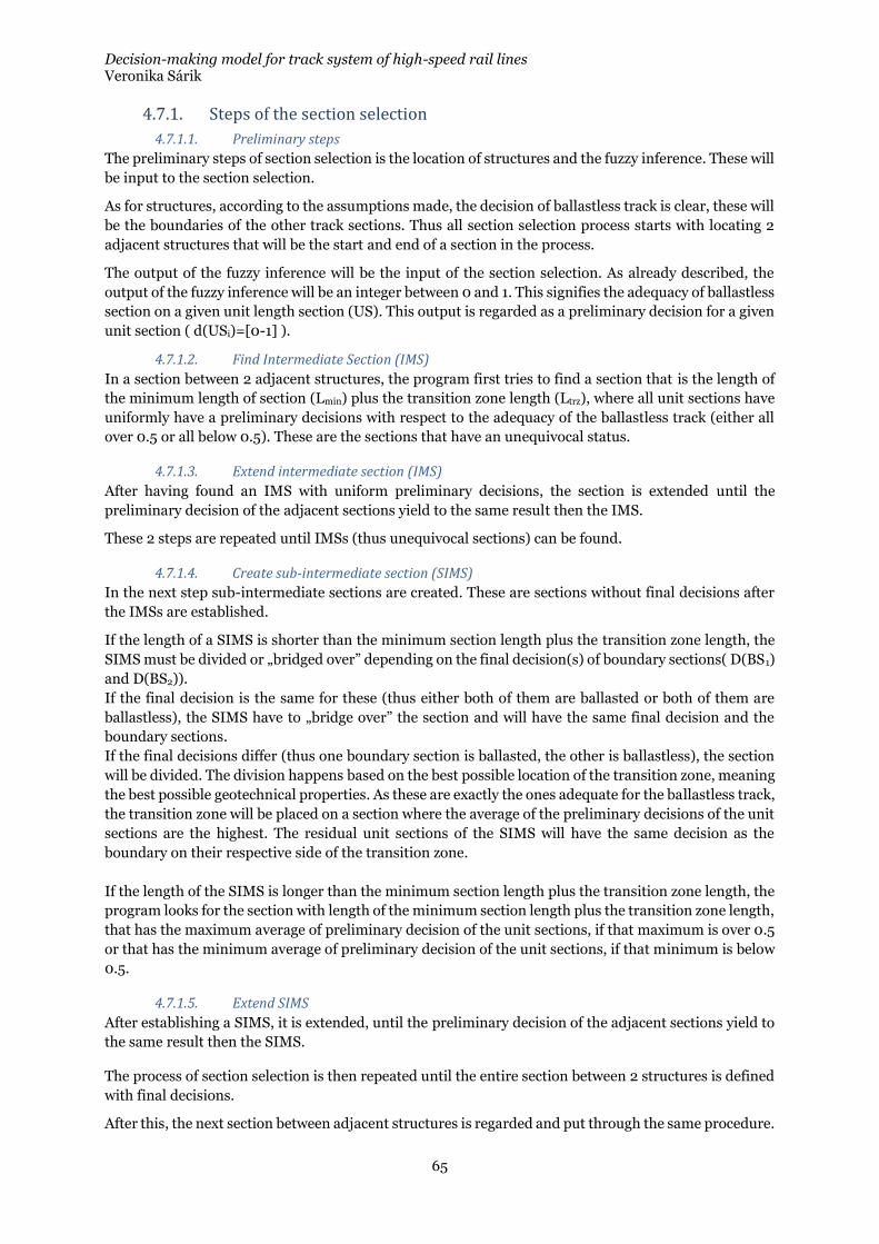
Decision-making model for track system of high-speed rail lines Veronika Sárik
65
4.7.1. Steps of the section selection
4.7.1.1. Preliminary steps
The preliminary steps of section selection is the location of structures and the fuzzy inference. These will
be input to the section selection.
As for structures, according to the assumptions made, the decision of ballastless track is clear, these will
be the boundaries of the other track sections. Thus all section selection process starts with locating 2
adjacent structures that will be the start and end of a section in the process.
The output of the fuzzy inference will be the input of the section selection. As already described, the
output of the fuzzy inference will be an integer between 0 and 1. This signifies the adequacy of ballastless
section on a given unit length section (US). This output is regarded as a preliminary decision for a given
unit section ( d(USi)=[0-1] ).
4.7.1.2. Find Intermediate Section (IMS)
In a section between 2 adjacent structures, the program first tries to find a section that is the length of
the minimum length of section (Lmin) plus the transition zone length (Ltrz), where all unit sections have
uniformly have a preliminary decisions with respect to the adequacy of the ballastless track (either all
over 0.5 or all below 0.5). These are the sections that have an unequivocal status.
4.7.1.3. Extend intermediate section (IMS)
After having found an IMS with uniform preliminary decisions, the section is extended until the
preliminary decision of the adjacent sections yield to the same result then the IMS.
These 2 steps are repeated until IMSs (thus unequivocal sections) can be found.
4.7.1.4. Create sub-intermediate section (SIMS)
In the next step sub-intermediate sections are created. These are sections without final decisions after
the IMSs are established.
If the length of a SIMS is shorter than the minimum section length plus the transition zone length, the
SIMS must be divided or „bridged over” depending on the final decision(s) of boundary sections( D(BS1)
and D(BS2)).
If the final decision is the same for these (thus either both of them are ballasted or both of them are
ballastless), the SIMS have to „bridge over” the section and will have the same final decision and the
boundary sections.
If the final decisions differ (thus one boundary section is ballasted, the other is ballastless), the section
will be divided. The division happens based on the best possible location of the transition zone, meaning
the best possible geotechnical properties. As these are exactly the ones adequate for the ballastless track,
the transition zone will be placed on a section where the average of the preliminary decisions of the unit
sections are the highest. The residual unit sections of the SIMS will have the same decision as the
boundary on their respective side of the transition zone.
If the length of the SIMS is longer than the minimum section length plus the transition zone length, the
program looks for the section with length of the minimum section length plus the transition zone length,
that has the maximum average of preliminary decision of the unit sections, if that maximum is over 0.5
or that has the minimum average of preliminary decision of the unit sections, if that minimum is below
0.5.
4.7.1.5. Extend SIMS
After establishing a SIMS, it is extended, until the preliminary decision of the adjacent sections yield to
the same result then the SIMS.
The process of section selection is then repeated until the entire section between 2 structures is defined
with final decisions.
After this, the next section between adjacent structures is regarded and put through the same procedure.

Decision-making model for track system of high-speed rail lines Veronika Sárik
66
4.8. LCC As the final level of the decision making process an LCC calculation is put forward.
4.8.1. Main purpose and scope of the LCC analysis The primary purpose of this LCC analysis is to enable projected life cycle costs of the different technical
solutions of the high speed rail line to be taken into when making strategical decisions. As it is on a
strategic level, the analysis will be carried out using benchmark data and broad assessment of the future
costs. The following LCC analysis is a relative one, as it is used to evaluate alternative technical solutions
and their mixed use.
The parameters are adjusted to the Swedish requirements and conditions, thus the results will be applicable for Sweden, but with adjustment of the parameters, evaluation on other locations is also feasible.
4.8.2. Environmental analysis in LCC Within sustainability 3 main areas can be differentiated:
• Environmental: natural resources, air quality, land use, transportation, biodiversity, cultural heritage etc.
• Social: access, amenity, user comfort and satisfaction
• Economic: opportunities of employment, skills development, local businesses etc.
In this thesis it is only the environmental aspect of the sustainability is regarded in a direct manner, in form of equivalent CO2 emission calculation and integration to the model.
Social aspects are indirectly included as the cost of hindrances calculation include the time loss of passengers in case of delays or re-routed trains. However the overall evaluation of the social sustainability is not carried out due to the scope of the thesis.
4.8.3. Period of analysis and methods of economic evaluation As the basis of the LCC analysis is the „cradle to the grave” evaluation, the period of the analysis is the assumed service life of the ballastless track, starting value of 60 years.
This is an estimated value, as the ballastless track can have a service life between 40 and 80 (or according to some manufacturers up to 100) years. As this is one of the critical input value in the calculation, it will be later on included in the sensitivity analysis.
The costs over the period of analysis will be determined based on Net Present Value (NPV). This economic evaluation method is most commonly used in public the sector.
„The level of discount rate used can have a significant impact on the outcome of the analysis – potentially determining whether a scheme is financially viable, or whether one strategic option is preferable to another. It is therefore of key importance to select the appropriate rate. For public sector projects the discount rate may be prescribed by national treasuries (typically 3-5%)”
𝑋𝑁𝑃𝑉 =∑(𝐶𝑛 × 𝑞) = ∑𝐶𝑛
(1 + 𝑑)𝑛
𝑝
𝑛=1
Where
o Cn is the cost in year n o q is the discount factor o d is the expected real discount rate per annum o n is the number of years between the base date and the occurrence of the cost o p is the period of analysis
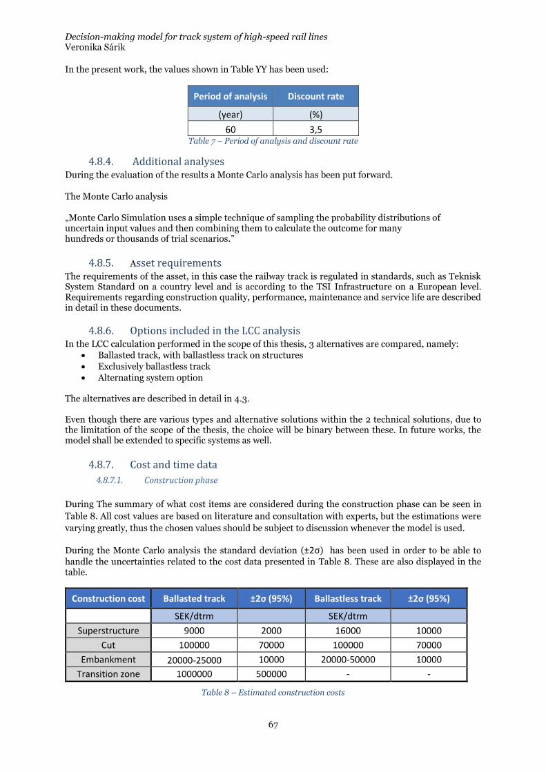
Decision-making model for track system of high-speed rail lines Veronika Sárik
67
In the present work, the values shown in Table YY has been used:
Period of analysis Discount rate
(year) (%)
60 3,5 Table 7 – Period of analysis and discount rate
4.8.4. Additional analyses During the evaluation of the results a Monte Carlo analysis has been put forward.
The Monte Carlo analysis
„Monte Carlo Simulation uses a simple technique of sampling the probability distributions of uncertain input values and then combining them to calculate the outcome for many hundreds or thousands of trial scenarios.”
4.8.5. Asset requirements The requirements of the asset, in this case the railway track is regulated in standards, such as Teknisk System Standard on a country level and is according to the TSI Infrastructure on a European level. Requirements regarding construction quality, performance, maintenance and service life are described in detail in these documents.
4.8.6. Options included in the LCC analysis In the LCC calculation performed in the scope of this thesis, 3 alternatives are compared, namely:
• Ballasted track, with ballastless track on structures
• Exclusively ballastless track
• Alternating system option The alternatives are described in detail in 4.3. Even though there are various types and alternative solutions within the 2 technical solutions, due to the limitation of the scope of the thesis, the choice will be binary between these. In future works, the model shall be extended to specific systems as well.
4.8.7. Cost and time data
4.8.7.1. Construction phase
During The summary of what cost items are considered during the construction phase can be seen in
Table 8. All cost values are based on literature and consultation with experts, but the estimations were
varying greatly, thus the chosen values should be subject to discussion whenever the model is used.
During the Monte Carlo analysis the standard deviation (±2σ) has been used in order to be able to
handle the uncertainties related to the cost data presented in Table 8. These are also displayed in the table.
Construction cost Ballasted track ±2σ (95%) Ballastless track ±2σ (95%)
SEK/dtrm SEK/dtrm
Superstructure 9000 2000 16000 10000
Cut 100000 70000 100000 70000
Embankment 20000-25000 10000 20000-50000 10000
Transition zone 1000000 500000 - -
Table 8 – Estimated construction costs
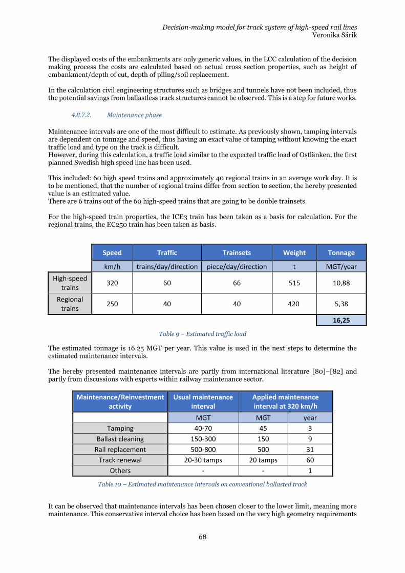
Decision-making model for track system of high-speed rail lines Veronika Sárik
68
The displayed costs of the embankments are only generic values, in the LCC calculation of the decision making process the costs are calculated based on actual cross section properties, such as height of embankment/depth of cut, depth of piling/soil replacement. In the calculation civil engineering structures such as bridges and tunnels have not been included, thus the potential savings from ballastless track structures cannot be observed. This is a step for future works.
4.8.7.2. Maintenance phase
Maintenance intervals are one of the most difficult to estimate. As previously shown, tamping intervals are dependent on tonnage and speed, thus having an exact value of tamping without knowing the exact traffic load and type on the track is difficult. However, during this calculation, a traffic load similar to the expected traffic load of Ostlänken, the first planned Swedish high speed line has been used. This included: 60 high speed trains and approximately 40 regional trains in an average work day. It is to be mentioned, that the number of regional trains differ from section to section, the hereby presented value is an estimated value. There are 6 trains out of the 60 high-speed trains that are going to be double trainsets. For the high-speed train properties, the ICE3 train has been taken as a basis for calculation. For the regional trains, the EC250 train has been taken as basis.
Speed Traffic Trainsets Weight Tonnage
km/h trains/day/direction piece/day/direction t MGT/year
High-speed trains
320 60 66 515 10,88
Regional trains
250 40 40 420 5,38
16,25
Table 9 – Estimated traffic load
The estimated tonnage is 16.25 MGT per year. This value is used in the next steps to determine the estimated maintenance intervals. The hereby presented maintenance intervals are partly from international literature [80]–[82] and partly from discussions with experts within railway maintenance sector.
Maintenance/Reinvestment activity
Usual maintenance interval
Applied maintenance interval at 320 km/h
MGT MGT year
Tamping 40-70 45 3
Ballast cleaning 150-300 150 9
Rail replacement 500-800 500 31
Track renewal 20-30 tamps 20 tamps 60
Others - - 1
Table 10 – Estimated maintenance intervals on conventional ballasted track
It can be observed that maintenance intervals has been chosen closer to the lower limit, meaning more maintenance. This conservative interval choice has been based on the very high geometry requirements
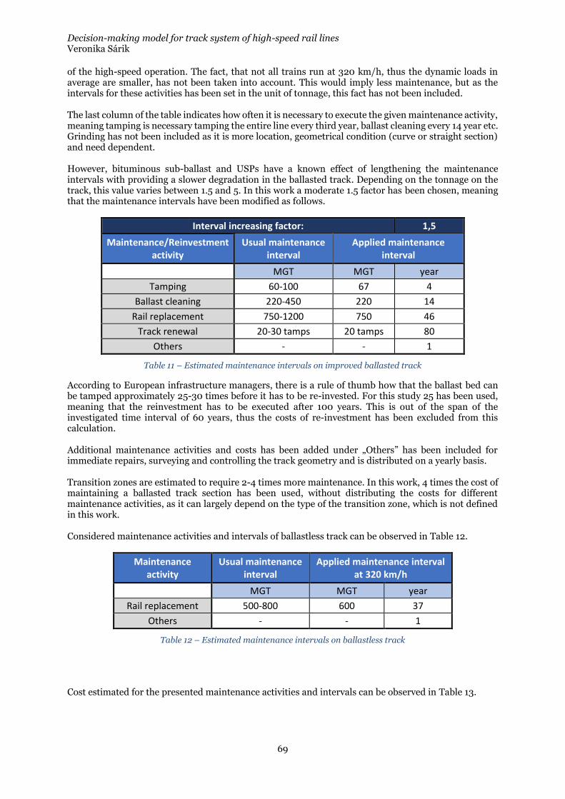
Decision-making model for track system of high-speed rail lines Veronika Sárik
69
of the high-speed operation. The fact, that not all trains run at 320 km/h, thus the dynamic loads in average are smaller, has not been taken into account. This would imply less maintenance, but as the intervals for these activities has been set in the unit of tonnage, this fact has not been included. The last column of the table indicates how often it is necessary to execute the given maintenance activity, meaning tamping is necessary tamping the entire line every third year, ballast cleaning every 14 year etc. Grinding has not been included as it is more location, geometrical condition (curve or straight section) and need dependent. However, bituminous sub-ballast and USPs have a known effect of lengthening the maintenance intervals with providing a slower degradation in the ballasted track. Depending on the tonnage on the track, this value varies between 1.5 and 5. In this work a moderate 1.5 factor has been chosen, meaning that the maintenance intervals have been modified as follows.
Interval increasing factor: 1,5
Maintenance/Reinvestment activity
Usual maintenance interval
Applied maintenance interval
MGT MGT year
Tamping 60-100 67 4
Ballast cleaning 220-450 220 14
Rail replacement 750-1200 750 46
Track renewal 20-30 tamps 20 tamps 80
Others - - 1
Table 11 – Estimated maintenance intervals on improved ballasted track
According to European infrastructure managers, there is a rule of thumb how that the ballast bed can be tamped approximately 25-30 times before it has to be re-invested. For this study 25 has been used, meaning that the reinvestment has to be executed after 100 years. This is out of the span of the investigated time interval of 60 years, thus the costs of re-investment has been excluded from this calculation. Additional maintenance activities and costs has been added under „Others” has been included for immediate repairs, surveying and controlling the track geometry and is distributed on a yearly basis. Transition zones are estimated to require 2-4 times more maintenance. In this work, 4 times the cost of maintaining a ballasted track section has been used, without distributing the costs for different maintenance activities, as it can largely depend on the type of the transition zone, which is not defined in this work. Considered maintenance activities and intervals of ballastless track can be observed in Table 12.
Maintenance activity
Usual maintenance interval
Applied maintenance interval at 320 km/h
MGT MGT year
Rail replacement 500-800 600 37
Others - - 1
Table 12 – Estimated maintenance intervals on ballastless track
Cost estimated for the presented maintenance activities and intervals can be observed in Table 13.
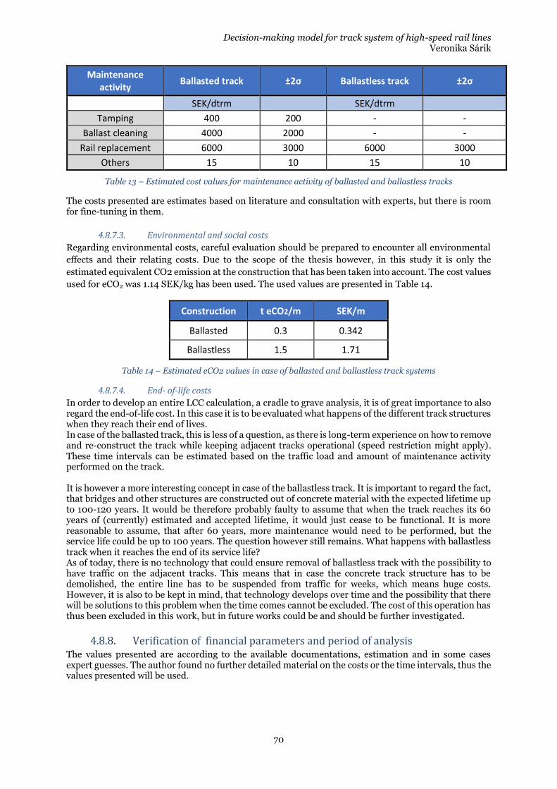
Decision-making model for track system of high-speed rail lines Veronika Sárik
70
Maintenance activity
Ballasted track ±2σ Ballastless track ±2σ
SEK/dtrm SEK/dtrm
Tamping 400 200 - -
Ballast cleaning 4000 2000 - -
Rail replacement 6000 3000 6000 3000
Others 15 10 15 10
Table 13 – Estimated cost values for maintenance activity of ballasted and ballastless tracks
The costs presented are estimates based on literature and consultation with experts, but there is room for fine-tuning in them.
4.8.7.3. Environmental and social costs
Regarding environmental costs, careful evaluation should be prepared to encounter all environmental
effects and their relating costs. Due to the scope of the thesis however, in this study it is only the
estimated equivalent CO2 emission at the construction that has been taken into account. The cost values
used for eCO2 was 1.14 SEK/kg has been used. The used values are presented in Table 14.
Construction t eCO2/m SEK/m
Ballasted 0.3 0.342
Ballastless 1.5 1.71
Table 14 – Estimated eCO2 values in case of ballasted and ballastless track systems
4.8.7.4. End- of-life costs
In order to develop an entire LCC calculation, a cradle to grave analysis, it is of great importance to also regard the end-of-life cost. In this case it is to be evaluated what happens of the different track structures when they reach their end of lives. In case of the ballasted track, this is less of a question, as there is long-term experience on how to remove and re-construct the track while keeping adjacent tracks operational (speed restriction might apply). These time intervals can be estimated based on the traffic load and amount of maintenance activity performed on the track. It is however a more interesting concept in case of the ballastless track. It is important to regard the fact, that bridges and other structures are constructed out of concrete material with the expected lifetime up to 100-120 years. It would be therefore probably faulty to assume that when the track reaches its 60 years of (currently) estimated and accepted lifetime, it would just cease to be functional. It is more reasonable to assume, that after 60 years, more maintenance would need to be performed, but the service life could be up to 100 years. The question however still remains. What happens with ballastless track when it reaches the end of its service life? As of today, there is no technology that could ensure removal of ballastless track with the possibility to have traffic on the adjacent tracks. This means that in case the concrete track structure has to be demolished, the entire line has to be suspended from traffic for weeks, which means huge costs. However, it is also to be kept in mind, that technology develops over time and the possibility that there will be solutions to this problem when the time comes cannot be excluded. The cost of this operation has thus been excluded in this work, but in future works could be and should be further investigated.
4.8.8. Verification of financial parameters and period of analysis The values presented are according to the available documentations, estimation and in some cases expert guesses. The author found no further detailed material on the costs or the time intervals, thus the values presented will be used.
Decision-making model for track system of high-speed rail lines Veronika Sárik
71
4.8.9. Economic evaluation and presentation of results The evaluation and presentation of the results is executed in the following chapter, where the decision-making model and the result of the LCC is presented through a case study.
4.8.10. Uncertainty analysis During an LCC calculation a crucial aspect is the reliability of the input data, regarding both costs and time intervals. Great number of estimation, rule of thumbs, assumptions exist and have been made in this work as well, but it is important to have a result that can be considered robust. [19] In order to handle the uncertainties of the input data, a Monte Carlo analysis has been performed. During the Monte Carlo analysis the input parameters are considered to be random variables within the pre-set boundaries formed by standard deviation. From these samples are drawn and the calculations are performed. With the outcomes the normal distribution is approximated and the specific outcome can be deduced for a set level of confidence. [19] The Monte Carlo analysis were used on the cost data, as the estimations of the different construction and maintenance activities varied greatly. In Table 8 and Table 10 the standard deviations can be observed at 95% confidence intervals. These has been used to estimate the upper and lower limit of the respective cost items. The Monte Carlo analysis has been performed with 10000 simulation steps. To illustrate the functionality of the analysis, it has been performed on the results of the presented
case study.

Decision-making model for track system of high-speed rail lines Veronika Sárik
72
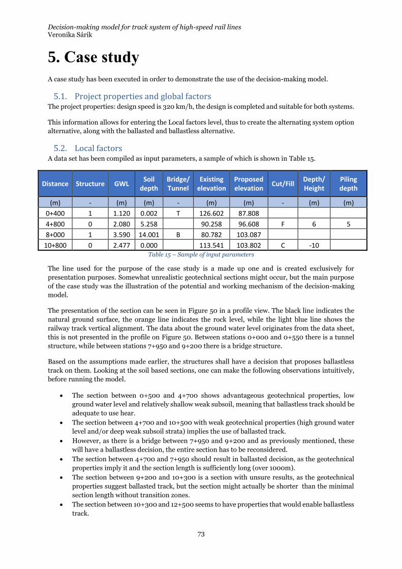
Decision-making model for track system of high-speed rail lines Veronika Sárik
73
5. Case study
A case study has been executed in order to demonstrate the use of the decision-making model.
5.1. Project properties and global factors The project properties: design speed is 320 km/h, the design is completed and suitable for both systems.
This information allows for entering the Local factors level, thus to create the alternating system option
alternative, along with the ballasted and ballastless alternative.
5.2. Local factors A data set has been compiled as input parameters, a sample of which is shown in Table 15.
Distance Structure GWL Soil
depth Bridge/ Tunnel
Existing elevation
Proposed elevation
Cut/Fill Depth/ Height
Piling depth
(m) - (m) (m) - (m) (m) - (m) (m)
0+400 1 1.120 0.002 T 126.602 87.808
4+800 0 2.080 5.258 90.258 96.608 F 6 5
8+000 1 3.590 14.001 B 80.782 103.087
10+800 0 2.477 0.000 113.541 103.802 C -10 Table 15 – Sample of input parameters
The line used for the purpose of the case study is a made up one and is created exclusively for
presentation purposes. Somewhat unrealistic geotechnical sections might occur, but the main purpose
of the case study was the illustration of the potential and working mechanism of the decision-making
model.
The presentation of the section can be seen in Figure 50 in a profile view. The black line indicates the
natural ground surface, the orange line indicates the rock level, while the light blue line shows the
railway track vertical alignment. The data about the ground water level originates from the data sheet,
this is not presented in the profile on Figure 50. Between stations 0+000 and 0+550 there is a tunnel
structure, while between stations 7+950 and 9+200 there is a bridge structure.
Based on the assumptions made earlier, the structures shall have a decision that proposes ballastless
track on them. Looking at the soil based sections, one can make the following observations intuitively,
before running the model.
• The section between 0+500 and 4+700 shows advantageous geotechnical properties, low
ground water level and relatively shallow weak subsoil, meaning that ballastless track should be
adequate to use hear.
• The section between 4+700 and 10+500 with weak geotechnical properties (high ground water
level and/or deep weak subsoil strata) implies the use of ballasted track.
• However, as there is a bridge between 7+950 and 9+200 and as previously mentioned, these
will have a ballastless decision, the entire section has to be reconsidered.
• The section between 4+700 and 7+950 should result in ballasted decision, as the geotechnical
properties imply it and the section length is sufficiently long (over 1000m).
• The section between 9+200 and 10+300 is a section with unsure results, as the geotechnical
properties suggest ballasted track, but the section might actually be shorter than the minimal
section length without transition zones.
• The section between 10+300 and 12+500 seems to have properties that would enable ballastless
track.
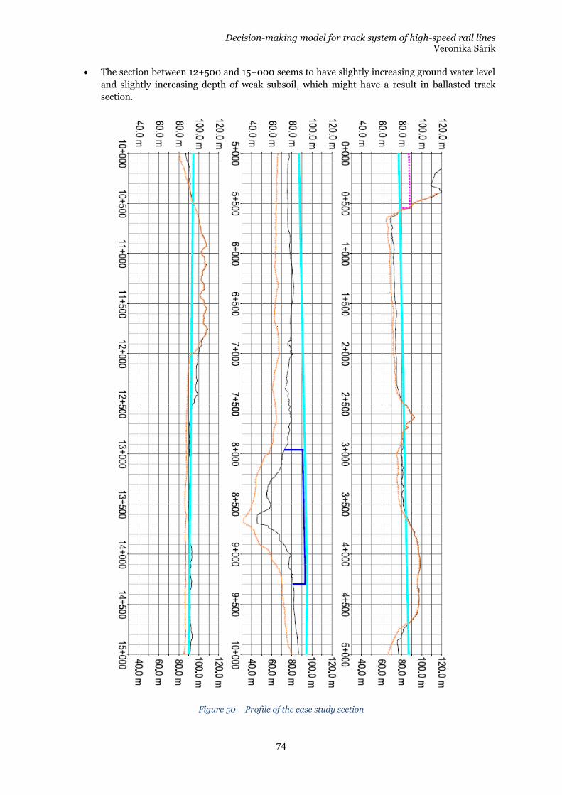
Decision-making model for track system of high-speed rail lines Veronika Sárik
74
• The section between 12+500 and 15+000 seems to have slightly increasing ground water level
and slightly increasing depth of weak subsoil, which might have a result in ballasted track
section.
Figure 50 – Profile of the case study section
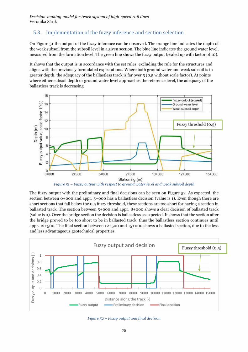
Decision-making model for track system of high-speed rail lines Veronika Sárik
75
5.3. Implementation of the fuzzy inference and section selection
On Figure 51 the output of the fuzzy inference can be observed. The orange line indicates the depth of
the weak subsoil from the subsoil level in a given section. The blue line indicates the ground water level,
measured from the formation level. The green line shows the fuzzy output (scaled up with factor of 10).
It shows that the output is in accordance with the set rules, excluding the rule for the structures and
aligns with the previously formulated expectations. Where both ground water and weak subsoil is in
greater depth, the adequacy of the ballastless track is far over 5 (0,5 without scale factor). At points
where either subsoil depth or ground water level approaches the reference level, the adequacy of the
ballastless track is decreasing.
Figure 51 – Fuzzy output with respect to ground water level and weak subsoil depth
The fuzzy output with the preliminary and final decisions can be seen on Figure 52. As expected, the
section between 0+000 and appr. 5+000 has a ballastless decision (value is 1). Even though there are
short sections that fall below the 0,5 fuzzy threshold, these sections are too short for having a section in
ballasted track. The section between 5+000 and appr. 8+000 shows a clear decision of ballasted track
(value is 0). Over the bridge section the decision is ballastless as expected. It shows that the section after
the bridge proved to be too short to be in ballasted track, thus the ballastless section continues until
appr. 12+500. The final section between 12+500 and 15+000 shows a ballasted section, due to the less
and less advantageous geotechnical properties.
Figure 52 – Fuzzy output and final decision
0
0,2
0,4
0,6
0,8
1
0 1000 2000 3000 4000 5000 6000 7000 8000 9000 10000 11000 12000 13000 14000 15000
Fuzz
y o
utp
ut
and
dec
isio
ns
(-)
Distance along the track (-)
Fuzzy output and decision
Fuzzy output Preliminary decision Final decision
Fuzzy threshold (0.5)
Fuzzy threshold (0.5)
Fuzzy threshold (0.5)
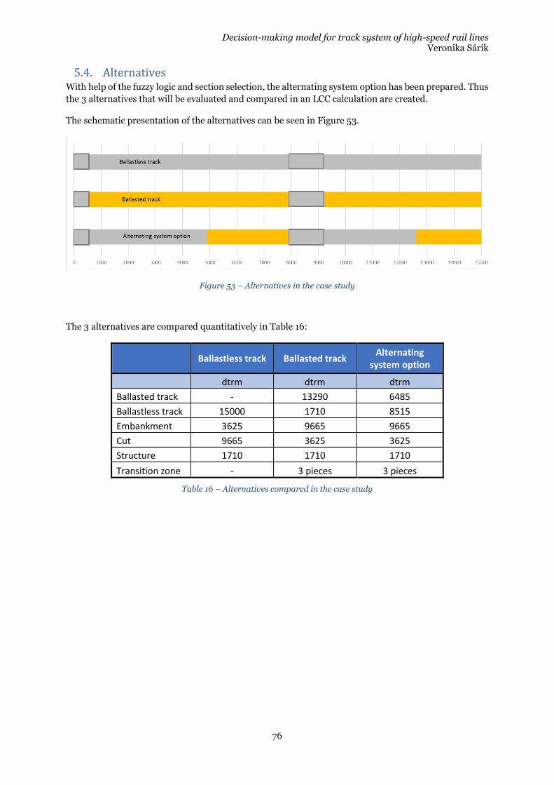
Decision-making model for track system of high-speed rail lines Veronika Sárik
76
5.4. Alternatives With help of the fuzzy logic and section selection, the alternating system option has been prepared. Thus
the 3 alternatives that will be evaluated and compared in an LCC calculation are created.
The schematic presentation of the alternatives can be seen in Figure 53.
Figure 53 – Alternatives in the case study
The 3 alternatives are compared quantitatively in Table 16:
Ballastless track Ballasted track
Alternating system option
dtrm dtrm dtrm
Ballasted track - 13290 6485
Ballastless track 15000 1710 8515
Embankment 3625 9665 9665
Cut 9665 3625 3625
Structure 1710 1710 1710
Transition zone - 3 pieces 3 pieces
Table 16 – Alternatives compared in the case study
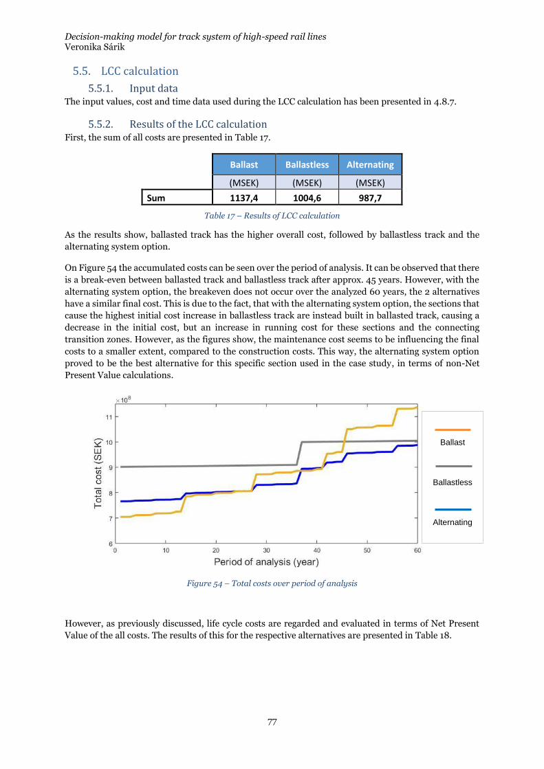
Decision-making model for track system of high-speed rail lines Veronika Sárik
77
5.5. LCC calculation
5.5.1. Input data The input values, cost and time data used during the LCC calculation has been presented in 4.8.7.
5.5.2. Results of the LCC calculation First, the sum of all costs are presented in Table 17.
Ballast Ballastless Alternating
(MSEK) (MSEK) (MSEK)
Sum 1137,4 1004,6 987,7
Table 17 – Results of LCC calculation
As the results show, ballasted track has the higher overall cost, followed by ballastless track and the
alternating system option.
On Figure 54 the accumulated costs can be seen over the period of analysis. It can be observed that there
is a break-even between ballasted track and ballastless track after approx. 45 years. However, with the
alternating system option, the breakeven does not occur over the analyzed 60 years, the 2 alternatives
have a similar final cost. This is due to the fact, that with the alternating system option, the sections that
cause the highest initial cost increase in ballastless track are instead built in ballasted track, causing a
decrease in the initial cost, but an increase in running cost for these sections and the connecting
transition zones. However, as the figures show, the maintenance cost seems to be influencing the final
costs to a smaller extent, compared to the construction costs. This way, the alternating system option
proved to be the best alternative for this specific section used in the case study, in terms of non-Net
Present Value calculations.
Figure 54 – Total costs over period of analysis
However, as previously discussed, life cycle costs are regarded and evaluated in terms of Net Present
Value of the all costs. The results of this for the respective alternatives are presented in Table 18.
Ballast
Ballastless
Alternating
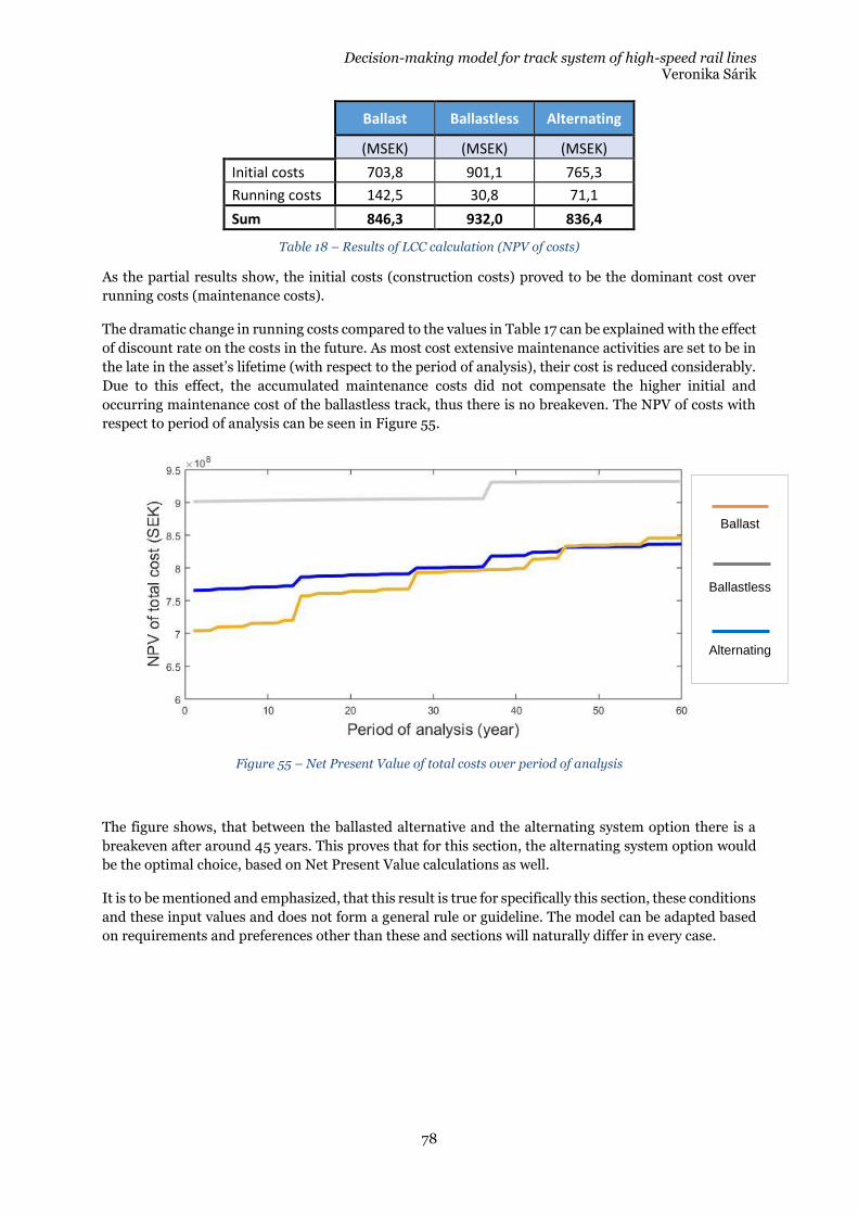
Decision-making model for track system of high-speed rail lines Veronika Sárik
78
Ballast Ballastless Alternating
(MSEK) (MSEK) (MSEK)
Initial costs 703,8 901,1 765,3
Running costs 142,5 30,8 71,1
Sum 846,3 932,0 836,4
Table 18 – Results of LCC calculation (NPV of costs)
As the partial results show, the initial costs (construction costs) proved to be the dominant cost over
running costs (maintenance costs).
The dramatic change in running costs compared to the values in Table 17 can be explained with the effect
of discount rate on the costs in the future. As most cost extensive maintenance activities are set to be in
the late in the asset’s lifetime (with respect to the period of analysis), their cost is reduced considerably.
Due to this effect, the accumulated maintenance costs did not compensate the higher initial and
occurring maintenance cost of the ballastless track, thus there is no breakeven. The NPV of costs with
respect to period of analysis can be seen in Figure 55.
Figure 55 – Net Present Value of total costs over period of analysis
The figure shows, that between the ballasted alternative and the alternating system option there is a
breakeven after around 45 years. This proves that for this section, the alternating system option would
be the optimal choice, based on Net Present Value calculations as well.
It is to be mentioned and emphasized, that this result is true for specifically this section, these conditions
and these input values and does not form a general rule or guideline. The model can be adapted based
on requirements and preferences other than these and sections will naturally differ in every case.
Ballast
Ballastless
Alternating
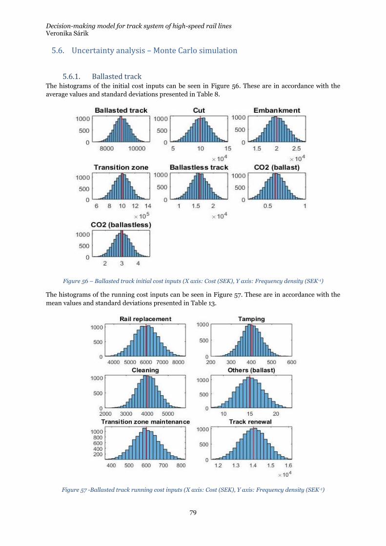
Decision-making model for track system of high-speed rail lines Veronika Sárik
79
5.6. Uncertainty analysis – Monte Carlo simulation
5.6.1. Ballasted track The histograms of the initial cost inputs can be seen in Figure 56. These are in accordance with the
average values and standard deviations presented in Table 8.
Figure 56 – Ballasted track initial cost inputs (X axis: Cost (SEK), Y axis: Frequency density (SEK-1)
The histograms of the running cost inputs can be seen in Figure 57. These are in accordance with the
mean values and standard deviations presented in Table 13.
Figure 57 -Ballasted track running cost inputs (X axis: Cost (SEK), Y axis: Frequency density (SEK-1)
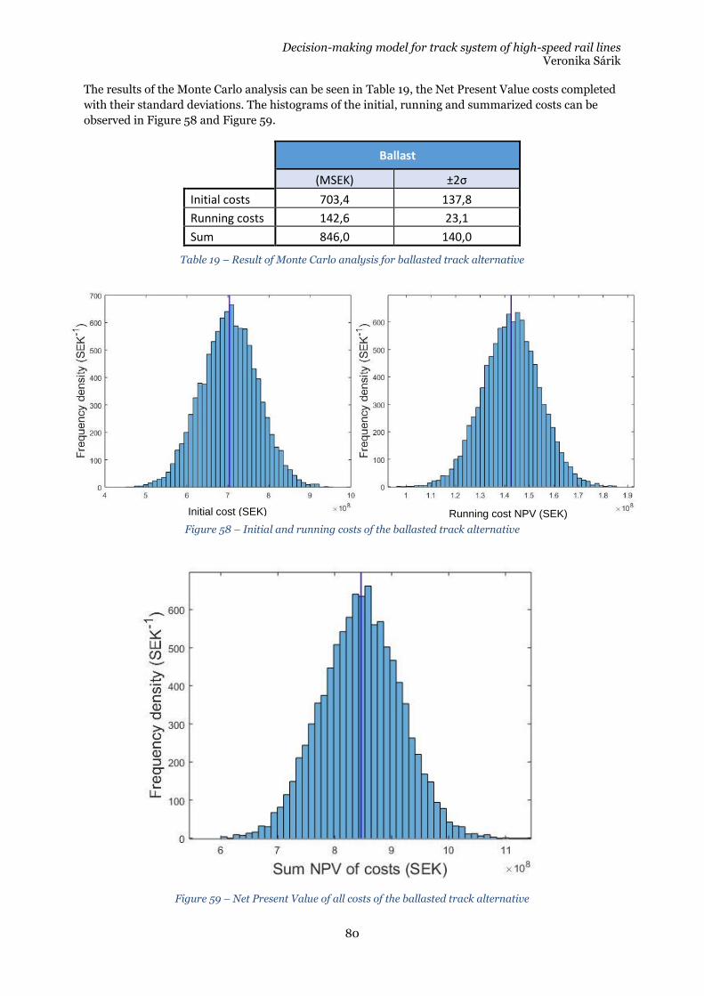
Decision-making model for track system of high-speed rail lines Veronika Sárik
80
The results of the Monte Carlo analysis can be seen in Table 19, the Net Present Value costs completed
with their standard deviations. The histograms of the initial, running and summarized costs can be
observed in Figure 58 and Figure 59.
Ballast
(MSEK) ±2σ
Initial costs 703,4 137,8
Running costs 142,6 23,1
Sum 846,0 140,0
Table 19 – Result of Monte Carlo analysis for ballasted track alternative
Figure 59 – Net Present Value of all costs of the ballasted track alternative
Figure 58 – Initial and running costs of the ballasted track alternative
Initial cost (SEK) Running cost NPV (SEK)
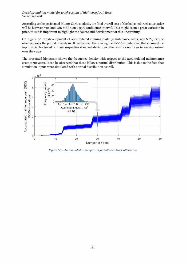
Decision-making model for track system of high-speed rail lines Veronika Sárik
81
According to the performed Monte-Carlo analysis, the final overall cost of the ballasted track alternative
will be between 706 and 986 MSEK on a 95% confidence interval. This might seem a great variation in
price, thus it is important to highlight the source and development of this uncertainty.
On Figure 60 the development of accumulated running costs (maintenance costs, not NPV) can be
observed over the period of analysis. It can be seen that during the 10000 simulations, that changed the
input variables based on their respective standard deviations, the results vary to an increasing extent
over the years.
The presented histogram shows the frequency density with respect to the accumulated maintenance
costs at 30 years. It can be observed that these follow a normal distribution. This is due to the fact, that
simulation inputs were simulated with normal distribution as well.
Figure 60 – Accumulated running costs for ballasted track alternative
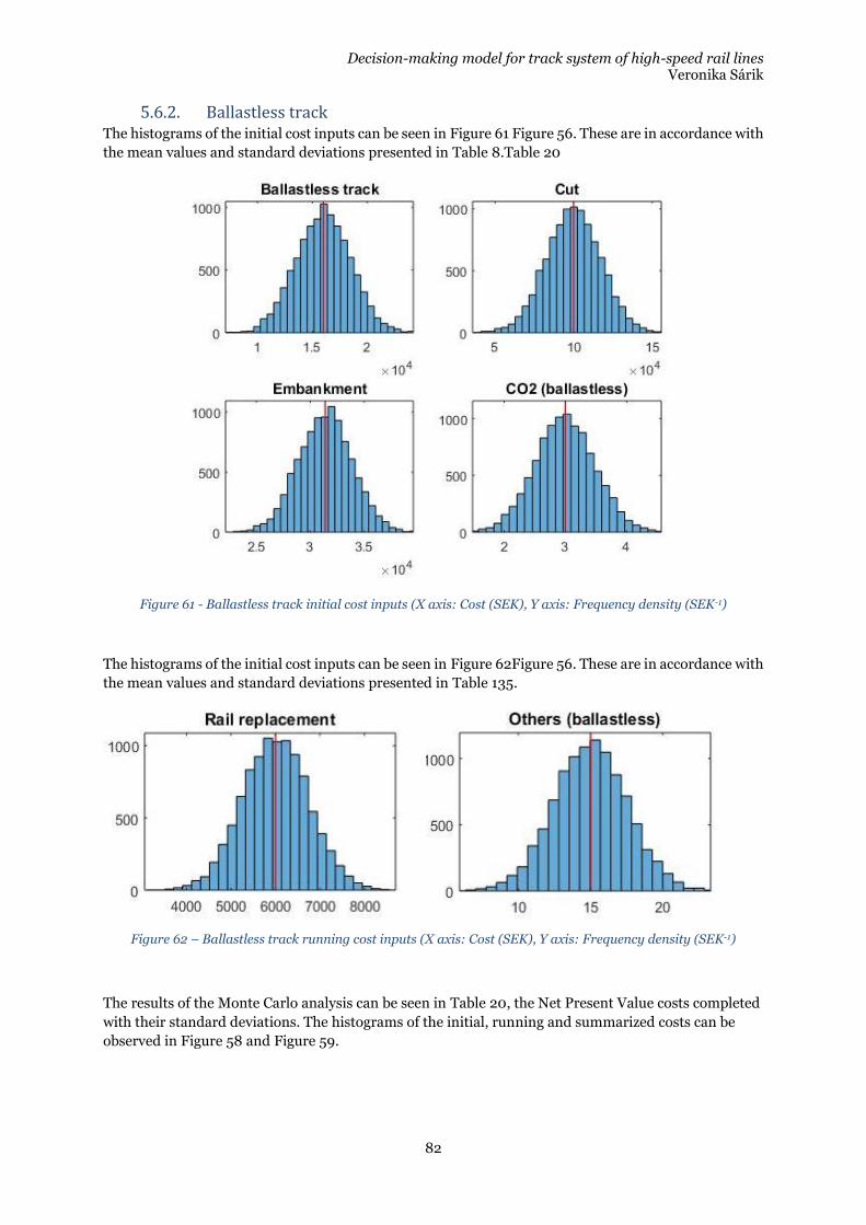
Decision-making model for track system of high-speed rail lines Veronika Sárik
82
5.6.2. Ballastless track The histograms of the initial cost inputs can be seen in Figure 61 Figure 56. These are in accordance with
the mean values and standard deviations presented in Table 8.Table 20
Figure 61 - Ballastless track initial cost inputs (X axis: Cost (SEK), Y axis: Frequency density (SEK-1)
The histograms of the initial cost inputs can be seen in Figure 62Figure 56. These are in accordance with
the mean values and standard deviations presented in Table 135.
Figure 62 – Ballastless track running cost inputs (X axis: Cost (SEK), Y axis: Frequency density (SEK-1)
The results of the Monte Carlo analysis can be seen in Table 20, the Net Present Value costs completed
with their standard deviations. The histograms of the initial, running and summarized costs can be
observed in Figure 58 and Figure 59.
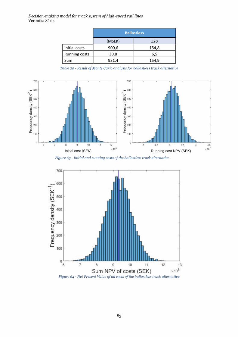
Decision-making model for track system of high-speed rail lines Veronika Sárik
83
Ballastless
(MSEK) ±2σ
Initial costs 900,6 154,8
Running costs 30,8 6,5
Sum 931,4 154,9
Table 20 - Result of Monte Carlo analysis for ballastless track alternative
Figure 64 - Net Present Value of all costs of the ballastless track alternative
Figure 63 - Initial and running costs of the ballastless track alternative
Initial cost (SEK) Running cost NPV (SEK)
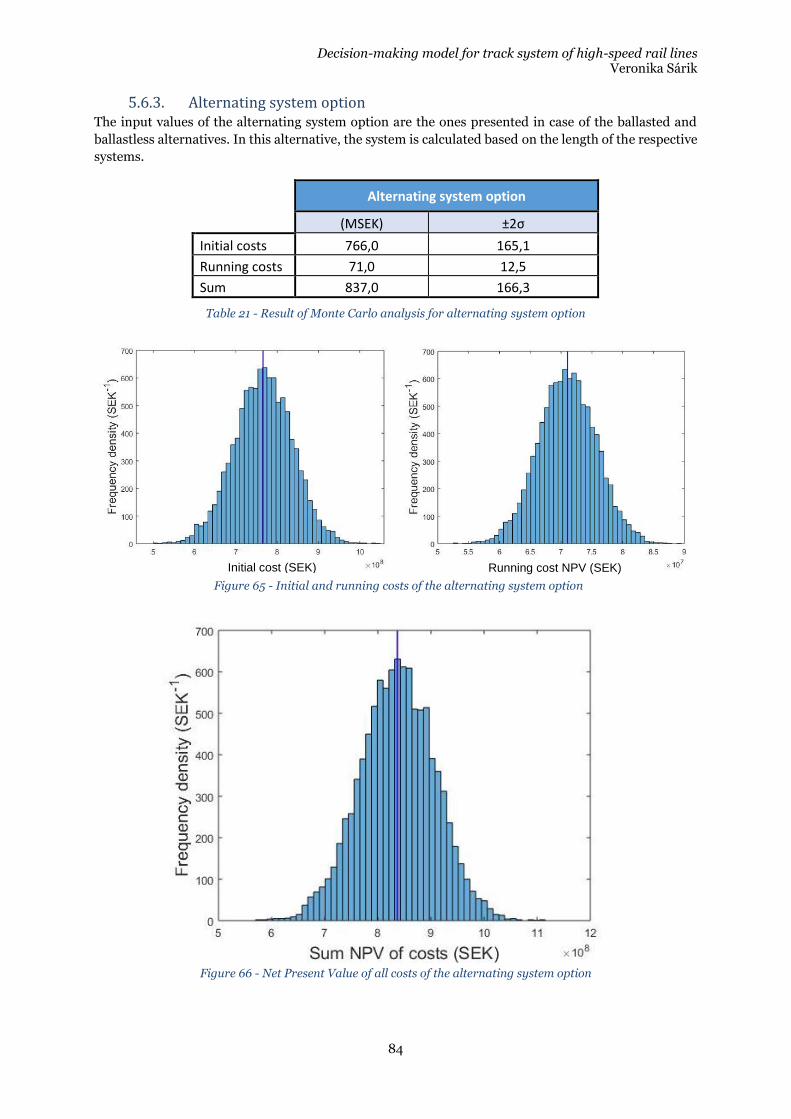
Decision-making model for track system of high-speed rail lines Veronika Sárik
84
5.6.3. Alternating system option The input values of the alternating system option are the ones presented in case of the ballasted and
ballastless alternatives. In this alternative, the system is calculated based on the length of the respective
systems.
Alternating system option
(MSEK) ±2σ
Initial costs 766,0 165,1
Running costs 71,0 12,5
Sum 837,0 166,3
Table 21 - Result of Monte Carlo analysis for alternating system option
Figure 66 - Net Present Value of all costs of the alternating system option
Figure 65 - Initial and running costs of the alternating system option
Initial cost (SEK) Running cost NPV (SEK)
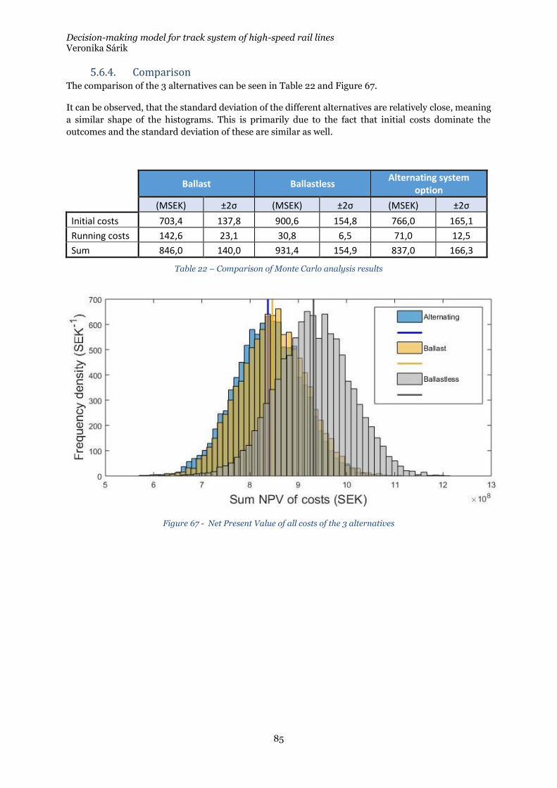
Decision-making model for track system of high-speed rail lines Veronika Sárik
85
5.6.4. Comparison The comparison of the 3 alternatives can be seen in Table 22 and Figure 67.
It can be observed, that the standard deviation of the different alternatives are relatively close, meaning
a similar shape of the histograms. This is primarily due to the fact that initial costs dominate the
outcomes and the standard deviation of these are similar as well.
Ballast Ballastless
Alternating system option
(MSEK) ±2σ (MSEK) ±2σ (MSEK) ±2σ
Initial costs 703,4 137,8 900,6 154,8 766,0 165,1
Running costs 142,6 23,1 30,8 6,5 71,0 12,5
Sum 846,0 140,0 931,4 154,9 837,0 166,3
Table 22 – Comparison of Monte Carlo analysis results
Figure 67 - Net Present Value of all costs of the 3 alternatives

Decision-making model for track system of high-speed rail lines Veronika Sárik
86
Decision-making model for track system of high-speed rail lines Veronika Sárik
87
6. Conclusion
During the presented thesis work, a systematic evaluation has been put forward regarding the
influencing factors that play a role when choosing track system as a high-speed rail line. The great
number of influencing factors imply it, but the author wishes to emphasize it, that there is no singular
answer to this question. It would not be correct to state, that one system is always the best option,
superior to the other.
Ballasted track is a system that has been used for over 150 years, which means extensive experience and
research on their behavior. Ballasted track, in order to be apt for high-speed use has gone through a
series of development, these are used across Europe with success. As of today, the use of ballasted track
cannot and should not be eliminated, as in case of moderate loading and/or maintenance interval
extending measures, its competitiveness with ballastless track is still to be acknowledged.
Ballastless track systems are entirely engineered, well-designed systems, with high performance and low
maintenance requirements. It can be stated, that ballastless track systems are tested and proven over
time, however entire life-time experiences of the modern ballastless track systems over the now estimate
60+ years of life is still missing. These systems have clear advantage when it comes to maintenance costs
on otherwise maintenance extensive lines and can generally have a lower life-cycle costs compared to
ballasted track.
It is to be kept in mind however, that careful evaluation is necessary to justify the higher initial costs and
environmental costs of the system, especially when poor quality subsoil forms the base for the railway
embankment. Even higher dynamical loads and future developments that can decrease initial costs
might further improve competitiveness of the ballastless track systems.
Having said that, one must admit that the selection a track system is still a complex and difficult task.
The thesis is considered to achieve its original goals, as during the work:
• A great variety of expertise and knowledge has been included from experts from all relevant
sectors of the railway industry
• A thorough and extensive evaluation of the decision influencing factors has been presented and
used
• A generic, highly adjustable decision-making framework has been proposed in order to evaluate
the 3 alternatives (ballasted, ballastless and combined systems)
• For the basis of evaluation an LCC calculation has been put forward
• The uncertainties during the evaluation have been handled and assessed, through the
application of Fuzzy logic within the decision-making model and a Monte Carlo analysis during
the LCC calculation
• A case study has been used to illustrate the potential of the system
It is important to mention, that the results presented in the simplified case study are not aiming to
provide a general answer to this multilevel, complex question.
The main added value in the thesis is considered to be the systematic approach and evaluation of the
decision-influencing factors and the proposed framework of the decision-making model, not the actual
input and output values per se. These can be adjusted based on national circumstances, standards or
preferences.

Decision-making model for track system of high-speed rail lines Veronika Sárik
88
Decision-making model for track system of high-speed rail lines Veronika Sárik
89
7. Future work
There are great opportunities to extend, elaborate and tune the proposed model.
Further influencing factors should be included in the model, such as costs/benefits availability and cost
of operational hindrances, critical speed evaluation and detailed environmental evaluation and its cost
factors.
Other cost items have been ignored as well, such as construction costs and savings on civil engineering
structures such as bridges and tunnels, but also within the track structure, no differentiation has been
made for protection layer heights for the different systems. Other technical areas and their differentiated
costs could be included, as the railway does not only costs of the track. All these (and further) cost factors
could further elaborate or change the results of the calculation.
Another improvement opportunity would be to extend the model to be product specific within ballastless
track. There are great differences in requirements, performance and pricing within the currently
available solutions, that the thesis could not include. Switching from generic decision making to product
specific would allow infrastructure managers and other decision makers to pick the best possible
solution to their specific section.
Furthermore, all input data in this work is topic of discussion and in many cases estimates or even expert
guesses. These could be adjusted based on further information from the relevant administrations and
organizations.

Decision-making model for track system of high-speed rail lines Veronika Sárik
90
Decision-making model for track system of high-speed rail lines Veronika Sárik
91
8. References
[1] C. Esveld, Modern Railway Track, 2nd editio. MRT-Productions, 2001.
[2] B. Lichtberger, Track Compendium, 2nd editio. DVV Media Group GmbH | Eurailpress, 2011.
[3] G. Michas, “Slab Track Systems for High-Speed Railways,” Inst. Technol. Stock., p. 95, 2012.
[4] Voies Ferrés des Landes, “Bordeaux/Dax,” Retrieved: 2018/03/05, 2009. .
[5] G. Jing, “High-Speed Rail Ballast Flight and Measures,” 2016.
[6] G. Q. Jing, Y. D. Zhou, J. Lin, and J. Zhang, “Ballast flying mechanism and sensitivity factors analysis,” Int. J. Smart Sens. Intell. Syst., vol. 5, no. 4, pp. 928–939, 2012.
[7] P. Teixeira, A. López-Pita, C. Casas, A. Bachiller, and F. Robusté, “Improvements in High-Speed Ballasted Track Design: Benefits of Bituminous Sub-ballast Layers,” Transp. Res. Rec. J. Transp. Res. Board, vol. 1943, no. 1943, pp. 43–49, 2006.
[8] P. F. Teixeira, A. López Pita, and P. A. Ferreira, “New possibilities to reduce track costs on high-speed lines using a bituminous sub-ballast layer,” Int. J. Pavement Eng., vol. 11, no. 4, pp. 301–307, 2010.
[9] P. Veit, “Sustainable Track Life-Cycle-Costs of Track,” 2013.
[10] S. Marschnig and P. Veit, “Making a case for under-sleeper pads,” Int. Railw. journa, vol. Vol. 5, no. No. 1, pp. 27–29, 2011.
[11] G. D’Angelo, N. Thom, and D. Lo Presti, “Bitumen stabilized ballast: A potential solution for railway track-bed,” Constr. Build. Mater., vol. 124, pp. 118–126, 2016.
[12] D. Ramirez Cardona, H. Di Benedetto, C. Sauzeat, N. Calon, and G. Saussine, “Use of a bituminous mixture layer in high-speed line trackbeds,” Constr. Build. Mater., vol. 125, pp. 398–407, 2016.
[13] S. Marschnig, “Ballasted track or slab track?,” no. May, 2016.
[14] R. Schilder and D. Diederich, “Installation Quality of Slab Track – A Decisive Factor for Maintenance,” RTR Spec., pp. 76–78, 2007.
[15] E. Darr, “Ballastless Track: Design,Types, Track Stability, Maintenance and System Comparison,” RTR. Hestra-Verlag, Hamburg. 2000.
[16] Porr, “Slab Track Austria - System ÖBB-PORR elastically supported slab.” 2012.
[17] Rail.One, “Rheda 2000 ® BALLASTLESS TRACK SYSTEM.” 2011.
[18] The European Commision, “Technical specifications for interoperability relating to the ‘infrastructure’ subsystem of the rail system in the European Union.” 2014.
[19] A. Zoeteman, “Life cycle cost analysis for managing rail infrastructure,” Eur. J. Transp. Infrastruct. Res., vol. 1, no. 4, pp. 391–413, 2001.
[20] W. Ebersohn and C. J. Ruppert, “Implementing a railway infrastructure maintenance system,” in CORE98 Conference, 1998.
[21] N. Fagan, “Choosing the Right Trackform for a High Speed Railway,” 2017.
[22] B. Marquis, “Cant Deficiency , Curving Speeds and Tilt,” Federal Railroad Administration. pp. 1–20, 2018.
[23] M. Lindahl, “Track geometry for high-speed railways,” Technology, 2001.
Decision-making model for track system of high-speed rail lines Veronika Sárik
92
[24] UIC, “Design of new lines for speeds of 300 – 350 km/h state of the art,” 2001.
[25] S. Bombach, “Selection of Cant for High-Speed Lines.” 2017.
[26] UIC - International Union of Railways, “Carbon Footprint of High Speed Rail.” 2011.
[27] R. L. Milford and J. M. Allwood, “Assessing the CO2impact of current and future rail track in the UK,” Transp. Res. Part D Transp. Environ., vol. 15, no. 2, pp. 61–72, 2010.
[28] J. Dakin and B. Stewart, “Reducing Noise & Vibration for High Speed Rail,” no. October, 2016.
[29] B. He, X. Xiao, Q. Zhou, Y. Li, and X. Jin, “Investigation into external noise of a high-speed train at different speeds,” J. Zhejiang Univ. Sci. A, vol. 15, no. 12, pp. 1019–1033, 2014.
[30] UIC, “Feasibility study « ballastless track » Report - March 2002,” no. March, 2002.
[31] SSF Ingenieure, “Slab track systems on different substructures,” 2016.
[32] PANDROL, “ZLR PANDROL Fastening,” 2010.
[33] C. Esveld, “Avoidance of expansion joints in high-speed CWR track on long bridges,” Rail Engineering International Edition, no. 3. pp. 7–9, 1995.
[34] UIC, Code UIC 719R. 2003.
[35] A. M. Tareen, “Geotechnical investigations (soil explorations),” 2015. .
[36] V. Ramachandran, “Soil investigations for foundations,” 2010. .
[37] W. Nawrat, “| Dependency between super- and substructure in ballastless track systems,” Presentation at PWI & UEEIV Fixed Track Forms for High Speed Lines. 2016.
[38] A. Alamaa, “High-speed railway embankments — a comparison of different regulations,” 2016.
[39] P. Boivin, “Shrinkage and Swelling Phenomena in Soils,” in Encyclopedia of Agrophysics, J. Gliński, J. Horabik, and J. Lipiec, Eds. Dordrecht: Springer Netherlands, 2011, pp. 733–735.
[40] E. Penner, “Ground Freezing and Frost Heaving,” Can. Build. Dig., 1962.
[41] G. Beskow, “Soil freezing and heaving with special application to roads and railroads,” Year B. 26, no. 3, Ser. C, no. 375. Stock. Sweden Swedish Geol. Surv., 1935.
[42] S. Zhang, D. Sheng, G. Zhao, F. Niu, and Z. He, “Analysis of frost heave mechanisms in a high-speed railway embankment,” Can. Geotech. J., vol. 53, no. 3, pp. 520–529, 2016.
[43] D. Sheng, S. Zhang, F. Niu, and G. Cheng, “A potential new frost heave mechanism in high-speed railway embankments,” Géotechnique, vol. 64, no. 2, pp. 144–154, 2014.
[44] G. D. Cheng, “The mechanism of repeated-segregation of the formation of thick layered ground ice.,” Cold Reg. Sci. Tech, vol. vol.8, no. No. 1, pp. 57–66, 1983.
[45] V. V. Krylov, “Generation of ground vibrations by superfast trains,” Appl. Acoust., vol. 44, no. 2, pp. 149–164, 1995.
[46] S. B. Mezher, D. P. Connolly, P. K. Woodward, O. Laghrouche, J. Pombo, and P. A. Costa, “Railway critical velocity - Analytical prediction and analysis,” Transp. Geotech., vol. 6, pp. 84–96, 2016.
[47] H. G. Jiang, X. C. Bian, and Y. M. Chen, “Impact of Water Level Rise on the Behaviors of Railway Track Structure and Substructure,” Transp. Res. Rec. J. Transp. Res. Board, vol. 2476, pp. 15–22, 2015.
[48] Hayward Baker, “Dynamic Compaction,” Retrieved: 2018/03/05, 2018. .
Decision-making model for track system of high-speed rail lines Veronika Sárik
93
[49] M. Gaafer, H. Bassioni, and T. Mostafa, “Soil Improvement Techniques,” Int. J. Sci. Eng. Res., vol. 6, no. 12, pp. 217–222, 2015.
[50] A. Yenco, “Decision Tree for Ground Improvement in Transportation,” 2013.
[51] G. P. Makusa, “State of the Art Review Soil Stabilization Methods and Materials,” J. STATE ART Rev., pp. 1–30, 2012.
[52] Trafikverket, “Teknisk systemstandard för höghastighetsbanor, krav v2.2,” 2016.
[53] Trafikverket, “Banöverbyggnad - Spårgeometri Krav på spårets geometri vid nybyggnad , reinvestering / upprustning , underhåll och drift,” 2015.
[54] SIS - Swedish Standards Institute, “SS-EN 13848-5:2017 Järnvägar – Spår – Spårlägeskvalitet – Del 5: Kvalitetsnivåer för spårläge – Spår och spårväxlar Railway applications – Track – Track geometry quality – Part 5: Geometric quality levels – Plain line, switches and crossings,” 2017.
[55] Trafikverket, “TDOK 2013:0347 Banöverbyggnad - Spårläge - krav vid nybygande och underhåll,” no. v 4.0. 2015.
[56] A. Prokopov and P. Nyström, “Spårkonstruktioner för 320 km / h - Övergångskonstruktioner,” pp. 1–38, 2011.
[57] H. Wang, L. Chang, and V. Markine, “Structural Health Monitoring of Railway Transition Zones Using Satellite Radar Data,” Sensors, vol. 18(2), no. 413, 2018.
[58] J.-A. Zakeri and V. Ghorbani, “Investigation on dynamic behavior of railway track in transition zone,” J. Mech. Sci. Technol., vol. 25, no. 2, pp. 287–292, 2011.
[59] K. Giannakos and S. Tsoukantas, “Transition Zone between Ballastless and Ballasted Track: Influence of Changing Stiffness on Acting Forces,” Procedia - Soc. Behav. Sci., vol. 48, pp. 3548–3557, 2012.
[60] P. Hölscher and P. Meijers, “Literature study of knowledge and experience of transition zones,” 2007.
[61] H. Lund and A. Åswärdh, “Transition zones between ballasted and ballastless tracks,” p. 65, 2014.
[62] Rhomberg Rail, “SIMPLE TRANSITION MODULE V-TRAS.”
[63] H. Heydari-Noghabi, J. N. Varandas, M. Esmaeili, and J. Zakeri, “Investigating the Influence of Auxiliary Rails on Dynamic Behavior of Railway Transition Zone by a 3D Train-Track Interaction Model,” Lat. Am. J. Solids Struct., vol. 14, pp. 2000–2018, 2017.
[64] SIS - Swedish Standards Institute, “SS-EN 16432-2:2017 Järnvägar – Ballastfria spårsystem – Del 2: Systemdesign, delsystem och komponenter Railway applications – Ballastless track systems – Part 2: System design, subsystems and components,” no. 112499, 2018.
[65] ASQ, “Tree Diagram,” Retrieved: 2018/03/05, 2018. .
[66] L. A. Zadeh, “Fuzzy Sets,” Inf. Control, no. 8, pp. 338–353, 1965.
[67] MathWorks, “Foundation of Fuzzy Logic,” Retrieved: 2018/03/05, 2018. .
[68] L. A. Zadeh, “Outline of a new approach to the analysis of complex systems and decision processes,” Syst. Man Cybern. IEEE Trans., no. 1, pp. 28–44, 1973.
[69] H. Koriath, A. Hamprecht, H. Huesmann, and P. Ablinger, “Bringing Objectivity into System Decisions between Ballasted Track and Slab Track at Deutsche Bahn ST ST,” RTR Hestra-Verlag, Hambg., vol. 2, no. 3, pp. 9–15, 2003.
[70] I. Gailienė and A. Laurinavičius, “The need and benefit of slab track : case of Lithuania,”
Decision-making model for track system of high-speed rail lines Veronika Sárik
94
Gradevinar, vol. 69, no. 5, pp. 387–396, 2017.
[71] D. Perez Martin and N. Fagan, “Methodology for trackform decisions - Slab track vs. Ballasted track,” Cordoba, 2015.
[72] S. J. Kirk and A. J. Dell’Isola, “Life Cycle Costing for Design Professionals,” 1995.
[73] S.-S. S. Institute, “SS-ISO 15686-5:2008.” 2008.
[74] R. Flanagan and G. Norman, “Life Cycle Costing for Construction,” Univ. Read. Reading, UK, 1983.
[75] INNOTRACK, “Concluding Technical Report,” 2010.
[76] C. Esveld, “Slab Track : A Competitive Solution,” Esveld Consult., pp. 1–5, 1999.
[77] S. K. Kondapalli and D. N. Billow, “Life Cycle Benefit of Concrete Slab Track,” in SN2860, Portland Cement Association, 2008.
[78] D. Langdon, “Life Cycle Costing (LCC) as a contribution to sustainable construction: a common methodology,” 2007.
[79] D. Langdon, “Life Cycle Costing (LCC) as a contribution to sustainable construction: a common methodology - Life cycle costing (LCC) as a contribution to sustainable construction Guidance on the use of the LCC Methodology and its application in public procurement,” no. May, p. 60, 2007.
[80] Z. Popović, L. Lazarević, L. J. Brajović, and P. Gladović, “Managing rail service life,” Metalurgija, vol. 53, no. 4, pp. 721–724, 2014.
[81] K. Tzanakakis, The Railway Track and Its Long Term Behaviour, 1st ed. Springer-Verlag Berlin Heidelberg, 2013.
[82] J. J. Kalker, D. F. Cannon, and O. Orringer, Rail Quality and Maintenance for Modern Railway Operation, 1st ed. Springer Netherlands, 1993.


DEGREE PROJECT IN THE BUILT ENVIRONMENTSTOCKHOLM, SWEDEN 2018
KTH ROYAL INSTITUTE OF TECHNOLOGYSCHOOL OF ARCHITECTURE AND THE BUILT ENVIRONMENTwww.kth.se
TRITA-ABE-MBT-186
Decision-making model for track system of high-speed rail linesBallasted track, ballastless track or both?
VERONIKA SÁRIK
VERONIKA SÁRIK D
ecision-making m
odel for track system of high-speed rail lines
KTH
2018