Embed Size (px)
Citation preview
TELANGANA ENERGY CONSERVATION BUILDING CODE (TSECBC) GUIDELINES
December 2017
Telangana Energy ConservationBuilding Code
Contents
1 Purpose 3
2 Scope 42.1 Applicable Building Systems . . . . . . . . . . . . . . . . . . . . . . . . . . . . . . . . . . . . . 42.2 Exemptions . . . . . . . . . . . . . . . . . . . . . . . . . . . . . . . . . . . . . . . . . . . . . . . 42.3 Safety, Health and Environmental Codes Take Precedence . . . . . . . . . . . . . . . . . . . . . 42.4 Reference Standards . . . . . . . . . . . . . . . . . . . . . . . . . . . . . . . . . . . . . . . . . . 4
3 Administration and Enforcement 53.1 Compliance Requirements . . . . . . . . . . . . . . . . . . . . . . . . . . . . . . . . . . . . . . . 53.2 Compliance Approaches . . . . . . . . . . . . . . . . . . . . . . . . . . . . . . . . . . . . . . . . 63.3 Administrative Requirements . . . . . . . . . . . . . . . . . . . . . . . . . . . . . . . . . . . . . 63.4 Compliance Documents . . . . . . . . . . . . . . . . . . . . . . . . . . . . . . . . . . . . . . . . 7
4 Envelope 94.1 General . . . . . . . . . . . . . . . . . . . . . . . . . . . . . . . . . . . . . . . . . . . . . . . . . 94.2 Mandatory Requirements . . . . . . . . . . . . . . . . . . . . . . . . . . . . . . . . . . . . . . . 94.3 Prescriptive Requirements . . . . . . . . . . . . . . . . . . . . . . . . . . . . . . . . . . . . . . . 94.4 Testing Standards . . . . . . . . . . . . . . . . . . . . . . . . . . . . . . . . . . . . . . . . . . . 10
5 Heating, Ventilation and Air conditioning 115.1 General . . . . . . . . . . . . . . . . . . . . . . . . . . . . . . . . . . . . . . . . . . . . . . . . . 115.2 Mandatory Requirements . . . . . . . . . . . . . . . . . . . . . . . . . . . . . . . . . . . . . . . 115.3 Prescriptive Requirements . . . . . . . . . . . . . . . . . . . . . . . . . . . . . . . . . . . . . . . 165.4 Testing Standards . . . . . . . . . . . . . . . . . . . . . . . . . . . . . . . . . . . . . . . . . . . 18
6 Service Hot Water and Pumping 196.1 General . . . . . . . . . . . . . . . . . . . . . . . . . . . . . . . . . . . . . . . . . . . . . . . . . 196.2 Mandatory Requirements . . . . . . . . . . . . . . . . . . . . . . . . . . . . . . . . . . . . . . . 196.3 Prescriptive Requirements . . . . . . . . . . . . . . . . . . . . . . . . . . . . . . . . . . . . . . . 206.4 Testing Standards . . . . . . . . . . . . . . . . . . . . . . . . . . . . . . . . . . . . . . . . . . . 20
7 Lighting 217.1 General . . . . . . . . . . . . . . . . . . . . . . . . . . . . . . . . . . . . . . . . . . . . . . . . . 217.2 Mandatory Requirements . . . . . . . . . . . . . . . . . . . . . . . . . . . . . . . . . . . . . . . 217.3 Prescriptive Requirements . . . . . . . . . . . . . . . . . . . . . . . . . . . . . . . . . . . . . . . 227.4 Testing Standard . . . . . . . . . . . . . . . . . . . . . . . . . . . . . . . . . . . . . . . . . . . . 25
8 Electrical Power 268.1 General . . . . . . . . . . . . . . . . . . . . . . . . . . . . . . . . . . . . . . . . . . . . . . . . . 268.2 Mandatory Requirements . . . . . . . . . . . . . . . . . . . . . . . . . . . . . . . . . . . . . . . 268.3 Prescriptive Requirement . . . . . . . . . . . . . . . . . . . . . . . . . . . . . . . . . . . . . . . 278.4 Testing Standard . . . . . . . . . . . . . . . . . . . . . . . . . . . . . . . . . . . . . . . . . . . . 27
A Definitions, Abbreviations and Acronyms 28A.1 General . . . . . . . . . . . . . . . . . . . . . . . . . . . . . . . . . . . . . . . . . . . . . . . . . 28A.2 Definitions . . . . . . . . . . . . . . . . . . . . . . . . . . . . . . . . . . . . . . . . . . . . . . . . 28A.3 Abbreviations and Acronyms . . . . . . . . . . . . . . . . . . . . . . . . . . . . . . . . . . . . . 37
B Whole Building Performance Method 40B.1 General . . . . . . . . . . . . . . . . . . . . . . . . . . . . . . . . . . . . . . . . . . . . . . . . . 40B.2 Simulation General Requirements . . . . . . . . . . . . . . . . . . . . . . . . . . . . . . . . . . . 40B.3 Calculation of Proposed Design and the Standard Design Performance . . . . . . . . . . . . . . 41
1
C Default Values for Typical Constructions 49C.1 Procedure for Determining Fenestration Product U-Factor and Solar Heat Gain Coefficient . . 49C.2 Default U-Factors and SHGC for Unrated Fenestration Products . . . . . . . . . . . . . . . . . 50C.3 Typical Roof constructions . . . . . . . . . . . . . . . . . . . . . . . . . . . . . . . . . . . . . . 50C.4 Typical wall constructions . . . . . . . . . . . . . . . . . . . . . . . . . . . . . . . . . . . . . . . 50
D Air Side Economizer Acceptance Procedures 52D.1 Construction Inspection . . . . . . . . . . . . . . . . . . . . . . . . . . . . . . . . . . . . . . . . 52D.2 Equipment Testing . . . . . . . . . . . . . . . . . . . . . . . . . . . . . . . . . . . . . . . . . . . 52
E Compliance Forms 53E.1 Envelope Summary . . . . . . . . . . . . . . . . . . . . . . . . . . . . . . . . . . . . . . . . . . . 53E.2 Building Permit Plans Checklist . . . . . . . . . . . . . . . . . . . . . . . . . . . . . . . . . . . 54E.3 Mechanical Summary . . . . . . . . . . . . . . . . . . . . . . . . . . . . . . . . . . . . . . . . . . 55E.4 Mechanical Checklist . . . . . . . . . . . . . . . . . . . . . . . . . . . . . . . . . . . . . . . . . . 56E.5 Lighting Summary . . . . . . . . . . . . . . . . . . . . . . . . . . . . . . . . . . . . . . . . . . . 57E.6 Lighting Permit Checklist . . . . . . . . . . . . . . . . . . . . . . . . . . . . . . . . . . . . . . . 58E.7 Electrical Power . . . . . . . . . . . . . . . . . . . . . . . . . . . . . . . . . . . . . . . . . . . . 59
2
1 Purpose
Background Note
The purpose of this code is to provide minimum requirements for the energy-e�cient design and construc-tion of buildings.
3
The states of Telangana and Andhra Pradesh adopted a mandatory Energy Conservation Building Code (ECBC) for commercial buildings in 2014, applicable to both states after bifurcation. To streamline and modernize compliance to the code, the Greater Hyderabad Municipal Corporation (GHMC) has devel-oped an online city-wide ECBC compliance system. The GHMC Town and Country Planning Depart-ment has integrated the compliance into the online Development Permission Management System (DPMS) for buildings approval. As knowledge partners, the Administrative Sta� College of India (ASCI), International Institute of Information Technology, Hyderabad (IIIT) and the Natural Resources Defense Council (NRDC) along with key experts have been working with state and city o�icials to develop and implement the code.
In this e�ort, the TS ECBC Guidelines is a technical document developed after several discussions, to aid and expedite the adoption of ECBC in the state of Telangana for real-estate developers, building architects, consultant and other stakeholders.
2 ScopeThe code is applicable to commercial buildings and other non-residential buildings that meet any of thefollowing criteria:
1. plot area of 1000 m2 or more
2. built up area of 2000 m2 or more
3. buildings primarily used as Multiplexes, Hospitals, Hotels or Convention Centers irrespective of theirbuilt up area
2.1 Applicable Building Systems
The provisions of this code shall apply to -
(a) Building envelopes, except for unconditioned storage spaces or warehouses;
(b) Mechanical systems and equipment, including heating, ventilating, and air conditioning;
(c) Service hot water heating;
(d) Interior and exterior lighting; and
(e) Electrical power and motors.
2.2 Exemptions
The provisions of this code shall not apply to
(a) Buildings that do not use either electricity or fossil fuel; or
(b) Equipment and portions of building systems that use energy primarily for manufacturing processes.
2.3 Safety, Health and Environmental Codes Take Precedence
Where this code is contrary to any of the provisions of laws relating to safety, health, or environment, theprovisions of safety, health or environmental laws shall apply.
2.4 Reference Standards
National Building Code 2016 is the reference document/standard for lighting levels, HVAC, comfort levels,and natural ventilation.
4
3 Administration and Enforcement
3.1 Compliance Requirements
3.1.1 Mandatory Requirements
(a) Compliance of this code shall be mandatory for buildings specified in section 2.
(b) All Government notifications related to energy conservation or mandatory use of any product/processor equipment shall be complied with.
3.1.2 New Buildings
New buildings shall comply with either the provisions of section 4 to 8 of this code or the Whole BuildingPerformance Method of Appendix B. In case of mixed use buildings if the commercial part qualifies for theapplicability of this code as per section 2 then the commercial part of the building need to comply with thiscode.
3.1.3 Additions to Existing Buildings
Where the addition plus the existing building exceeds the builtup area threshold of section 2, additionsshall comply with the provisions of section 4 to 8. Compliance may be demonstrated in either of the fol-lowing ways:
1. The addition alone shall comply with the applicable requirements, or
2. The addition, together with the entire existing building shall comply with the requirements of thiscode that would apply to the entire building, as if it were a new building:
Exception to section 3.1.3: When space conditioning is through the existing systems and equipment, the ex-isting system and equipment need not comply with this code. However, any new equipment installed mustcomply with specific requirements applicable to that equipment.
3.1.4 Alterations to Existing Buildings
Where the existing building exceeds the conditioned floor area threshold as specified in section 2, the por-tions of a building and its systems that are being altered shall meet the provisions of section 4 to 8. Thespecific requirements for alterations are described in the following subsections.
Exception to section 3.1.4: When the entire building complies with all of the provisions of section 4 to 8as if it were a new building.
3.1.4.1 Building Envelope
Alterations to the building envelope shall comply with the requirements of section 4 for fenestration, insula-tion, and air leakage applicable to the portions of the buildings and its systems being altered.
Exception to section 3.1.4.1: The following alterations need not comply with these requirements providedsuch alterations do not increase the energy usage of the building:
(a) Replacement of glass in an existing sash and frame, provided the U-factor and SHGC of the replace-ment glazing are equal to or lower than the existing glazing;
(b) Modifications to roof/ceiling, wall or floor cavities which are insulated to full depth with insulation;and
(c) Modifications to walls and floor without cavities and where no new cavities are created.
5
3.1.4.2 Heating, Ventilation and Air Conditioning
Alterations to building heating, ventilating, and air conditioning equipment or systems shall comply withthe requirements of section 5 applicable to the portions of the building and its systems being altered. Anynew equipment or control devices installed in conjunction with the alteration shall comply with the specificrequirements applicable to that equipment or control device.
3.1.4.3 Service Water Heating
Alterations to building service water heating equipment or systems shall comply with the requirements ofsection 6 applicable to the portions of the building and its systems being altered. Any new equipment orcontrol devices installed in conjunction with the alteration shall comply with the specific requirements ap-plicable to that equipment or control device.
3.1.4.4 Lighting
Alterations to building lighting equipment or system shall comply with the requirements of section 7 ap-plicable to the portions of the building and its systems being altered. New lighting systems, including con-trols, installed in an existing building and any change of building area type as listed in Table 7.1 shall beconsidered an alteration. Any new equipment or control devices installed in conjunction with the alterationshall comply with the specific requirements applicable to that equipment or control device.
Exception to section 3.1.4.4: Alterations that replace less than 50% of the luminaries in a space need notcomply with these requirements provided such alterations do not increase the connected lighting load.
3.1.4.5 Electric Power and Motors
Alteration to building electric power systems and motor shall comply with the requirements of section 8applicable to the portions of the building and its systems being altered. Any new equipment or control de-vices installed in conjunction with the alteration shall comply with the specific requirements applicable tothat equipment or control device.
3.2 Compliance Approaches
The building shall comply with the mandatory provisions of sections 4.2, 5.2, 6.2, 7.2, and 8.2; buildingcomponents shall be tested as per the provisions given in section 4.4, 5.4, 6.4, 7.4, and 8.4 and either of thefollowing:
(a) Prescriptive Method (sections 4.3, 5.3, 6.3, 7.3 and 8.3)
(b) Whole Building Performance Method of Appendix B
Consistent with Section 22 of Telangana Building Rules, 2012 and to encourage compliance, the ULB shalladopt the following compliance rating methodology as described in the Table 3.1. Compliance by prescrip-tive method to get TS* is mandatory for all the new buildings as per definition given in section 2(aa). How-ever, builder/owner/developer can adopt TS** and above on voluntary basis.
3.3 Administrative Requirements
Administrative requirements relating to permit requirements, enforcement, interpretations, claims of exemp-tion, approved calculation methods, and rights of appeal are specified by the Authority having Jurisdiction.
3.3.1 Professional Statement
Professional statement for energy analysis shall be prepared to identify the compliance format and to demon-strate how the project design and the construction complies with TSECBC.
3.3.2 Professional Responsibility
Professional responsibility for energy analysis and compliance for any method adopted by builder/owner/developershall be fixed on respective TS Empanelled architect or BEE empanelled architect who submits the profes-sional statement.
6
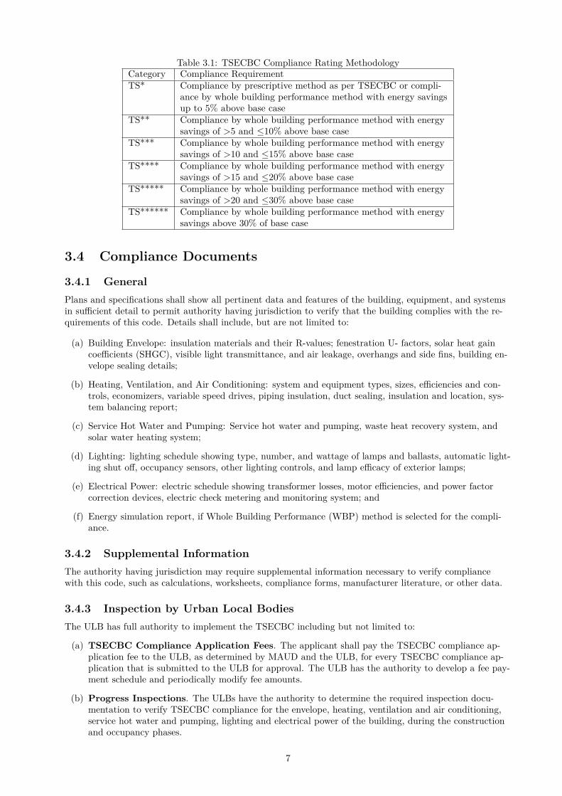
Table 3.1: TSECBC Compliance Rating MethodologyCategory Compliance RequirementTS* Compliance by prescriptive method as per TSECBC or compli-
ance by whole building performance method with energy savingsup to 5% above base case
TS** Compliance by whole building performance method with energysavings of >5 and ≤10% above base case
TS*** Compliance by whole building performance method with energysavings of >10 and ≤15% above base case
TS**** Compliance by whole building performance method with energysavings of >15 and ≤20% above base case
TS***** Compliance by whole building performance method with energysavings of >20 and ≤30% above base case
TS****** Compliance by whole building performance method with energysavings above 30% of base case
3.4 Compliance Documents
3.4.1 General
Plans and specifications shall show all pertinent data and features of the building, equipment, and systemsin sufficient detail to permit authority having jurisdiction to verify that the building complies with the re-quirements of this code. Details shall include, but are not limited to:
(a) Building Envelope: insulation materials and their R-values; fenestration U- factors, solar heat gaincoefficients (SHGC), visible light transmittance, and air leakage, overhangs and side fins, building en-velope sealing details;
(b) Heating, Ventilation, and Air Conditioning: system and equipment types, sizes, efficiencies and con-trols, economizers, variable speed drives, piping insulation, duct sealing, insulation and location, sys-tem balancing report;
(c) Service Hot Water and Pumping: Service hot water and pumping, waste heat recovery system, andsolar water heating system;
(d) Lighting: lighting schedule showing type, number, and wattage of lamps and ballasts, automatic light-ing shut off, occupancy sensors, other lighting controls, and lamp efficacy of exterior lamps;
(e) Electrical Power: electric schedule showing transformer losses, motor efficiencies, and power factorcorrection devices, electric check metering and monitoring system; and
(f) Energy simulation report, if Whole Building Performance (WBP) method is selected for the compli-ance.
3.4.2 Supplemental Information
The authority having jurisdiction may require supplemental information necessary to verify compliancewith this code, such as calculations, worksheets, compliance forms, manufacturer literature, or other data.
3.4.3 Inspection by Urban Local Bodies
The ULB has full authority to implement the TSECBC including but not limited to:
(a) TSECBC Compliance Application Fees. The applicant shall pay the TSECBC compliance ap-plication fee to the ULB, as determined by MAUD and the ULB, for every TSECBC compliance ap-plication that is submitted to the ULB for approval. The ULB has the authority to develop a fee pay-ment schedule and periodically modify fee amounts.
(b) Progress Inspections. The ULBs have the authority to determine the required inspection docu-mentation to verify TSECBC compliance for the envelope, heating, ventilation and air conditioning,service hot water and pumping, lighting and electrical power of the building, during the constructionand occupancy phases.
7
(c) Incentive Structures. The ULB and MAUD have the authority to provide incentives for compli-ance with TS*** or higher categories of the TSECBC Compliance Rating. The incentives may be inthe form of expedited processing of the certificate of construction and occupancy certificate filed bythe applicant.
(d) Energy Analysis Disclosure. The ULB has the authority to disclose the energy analysis results atany time.
(e) TSECBC Trainings and Education. The ULB is authorized to develop training for ULB staffand inspectors; education and outreach programs to design professionals; and programs for licensingprofessionals and inspectors on TSECBC compliance.
(f) Compliance and Enforcement. The ULB has broad authority to ensure compliance and take en-forcement actions for violations of this GO.
(i) The ULB has the authority to appeal to BEE to revoke the empanelment certification for BEEempanelled architects that sign TSECBC compliance applications for buildings found to be non-compliant.
(ii) The ULB has the authority to blacklist BEE empanelled architects that repeatedly submit non-compliant energy analysis or falsely any documents pursuant to this GO for TSECBC compli-ance.
(iii) The ULB has the authority to develop a program utilizing third party assessors or inspectors toensure compliance with the TSECBC.
8
4 Envelope
4.1 General
The building envelope shall comply with the mandatory provisions of section 4.2 and the prescriptive crite-ria of section 4.3. Building envelope components shall be tested as per the provisions given in section 4.4.
4.2 Mandatory Requirements
4.2.1 Fenestration: Light to Solar Gain (L/S)
Fenestration shall have ratio of Light to Solar Gain (L/S) not less than 1.
4.2.2 Building Envelope Sealing
The following areas of the enclosed building envelope shall be sealed, caulked, gasketed, or weather strippedto minimize air leakage
(a) Joints around fenestration and door frames;
(b) Openings between walls and foundations and between walls and roof and wall panels;
(c) Openings at penetrations of utility services through, roofs, walls, and floors;
(d) Site- built fenestration and doors;
(e) Building assemblies used as ducts or plenums; and
(f) All other openings in the building envelope.
4.2.3 Roof Surface
Roofs shall have initial solar reflectance of not less than 0.30 and an initial emittance no less than 0.75.
4.3 Prescriptive Requirements
4.3.1 Roofs
Roofs shall have the maximum assembly U-factor of 0.4 W/m2K.
4.3.1.1 Cool Roofs
Roofs with slopes less than 20 degrees shall have initial solar reflectance of not less than 0.70 and an initialemittance no less than 0.75.
4.3.2 Opaque Walls
Opaque walls shall have the maximum assembly U-factor of 0.73 W/m2K.
4.3.3 Vertical Fenestration
Vertical fenestration shall comply with area weighted U-factor, SHGC and VLT as given in Table 4.1. Ver-tical fenestration area is limited to a maximum of 60% of the gross wall area for the prescriptive require-ment.Exception to section 4.3.3: Overhangs and/or side fins may be applied in determining the SHGC for theproposed design. An adjusted SHGC, accounting for overhangs and/or side fins, is calculated by using thetool available at http://mfactor.ecbctool.inException to SHGC Requirements in section 4.4.3: Vertical Fenestration areas located more than 2.2 mabove the level of the floor (daylight glazing) are exempt from the SHGC requirement in Table 4.1 if thefollowing conditions are compiled with:-
9
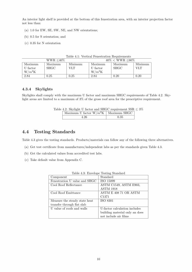
An interior light shelf is provided at the bottom of this fenestration area, with an interior projection factornot less than:
(a) 1.0 for EW, SE, SW, NE, and NW orientations;
(b) 0.5 for S orientation; and
(c) 0.35 for N orientation
Table 4.1: Vertical Fenestration RequirementsWWR ≤40% 40% < WWR ≤60%
MaximumU factorW/m2K
MaximumSHGC
MinimumVLT
MaximumU factorW/m2K
MaximumSHGC
MinimumVLT
2.84 0.25 0.25 2.84 0.20 0.20
4.3.4 Skylights
Skylights shall comply with the maximum U factor and maximum SHGC requirements of Table 4.2. Sky-light areas are limited to a maximum of 3% of the gross roof area for the prescriptive requirement.
Table 4.2: Skylight U factor and SHGC requirement SSR ≤ 3%Maximum U factor W/m2K Maximum SHGC
4.26 0.35
4.4 Testing Standards
Table 4.3 gives the testing standards. Products/materials can follow any of the following three alternatives.
(a) Get test certificate from manufactures/independent labs as per the standards given Table 4.3.
(b) Get the calculated values from accredited test labs.
(c) Take default value from Appendix C.
Table 4.3: Envelope Testing StandardComponent StandardFenestration U value and SHGC ISO 15099Cool Roof Reflectance ASTM C1549, ASTM E903,
ASTM 1918Cool Roof Emittance ASTM E 408 71 OR ASTM
C1371Measure the steady state heattransfer through flat slab
ISO 8301
U value of roofs and walls U-factor calculation includesbuilding material only an doesnot include air films
10
5 Heating, Ventilation and Air conditioning
5.1 General
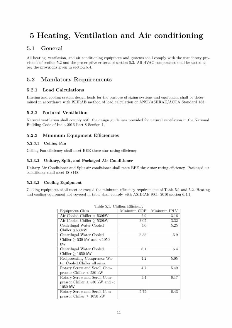
All heating, ventilation, and air conditioning equipment and systems shall comply with the mandatory pro-visions of section 5.2 and the prescriptive criteria of section 5.3. All HVAC components shall be tested asper the provisions given in section 5.4.
5.2 Mandatory Requirements
5.2.1 Load Calculations
Heating and cooling system design loads for the purpose of sizing systems and equipment shall be deter-mined in accordance with ISHRAE method of load calculation or ANSI/ASHRAE/ACCA Standard 183.
5.2.2 Natural Ventilation
Natural ventilation shall comply with the design guidelines provided for natural ventilation in the NationalBuilding Code of India 2016 Part 8 Section 1,
5.2.3 Minimum Equipment Efficiencies
5.2.3.1 Ceiling Fan
Ceiling Fan efficiency shall meet BEE three star rating efficiency.
5.2.3.2 Unitary, Split, and Packaged Air Conditioner
Unitary Air Conditioner and Split air conditioner shall meet BEE three star rating efficiency. Packaged airconditioner shall meet IS 8148.
5.2.3.3 Cooling Equipment
Cooling equipment shall meet or exceed the minimum efficiency requirements of Table 5.1 and 5.2. Heatingand cooling equipment not covered in table shall comply with ASHRAE 90.1- 2010 section 6.4.1.
Table 5.1: Chillers EfficiencyEquipment Class Minimum COP Minimum IPLVAir Cooled Chiller < 530kW 2.9 3.16Air Cooled Chiller ≥ 530kW 3.05 3.32Centrifugal Water CooledChiller ≤530kW
5.0 5.25
Centrifugal Water CooledChiller ≥ 530 kW and <1050kW
5.55 5.9
Centrifugal Water CooledChiller ≥ 1050 kW
6.1 6.4
Reciprocating Compressor Wa-ter Cooled Chiller all sizes
4.2 5.05
Rotary Screw and Scroll Com-pressor Chiller < 530 kW
4.7 5.49
Rotary Screw and Scroll Com-pressor Chiller ≥ 530 kW and <1050 kW
5.4 6.17
Rotary Screw and Scroll Com-pressor Chiller ≥ 1050 kW
5.75 6.43
11
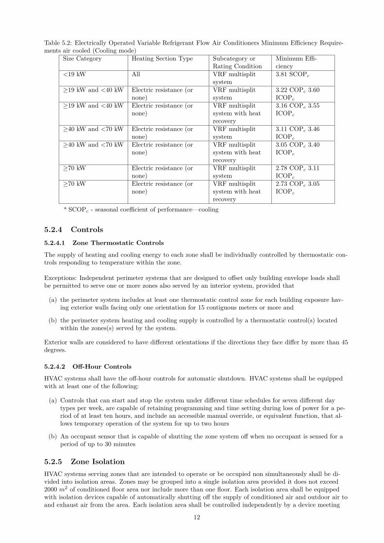
Table 5.2: Electrically Operated Variable Refrigerant Flow Air Conditioners Minimum Efficiency Require-ments air cooled (Cooling mode)
Size Category Heating Section Type Subcategory orRating Condition
Minimum Effi-ciency
<19 kW All VRF multisplitsystem
3.81 SCOPc
≥19 kW and <40 kW Electric resistance (ornone)
VRF multisplitsystem
3.22 COPc 3.60ICOPc
≥19 kW and <40 kW Electric resistance (ornone)
VRF multisplitsystem with heatrecovery
3.16 COPc 3.55ICOPc
≥40 kW and <70 kW Electric resistance (ornone)
VRF multisplitsystem
3.11 COPc 3.46ICOPc
≥40 kW and <70 kW Electric resistance (ornone)
VRF multisplitsystem with heatrecovery
3.05 COPc 3.40ICOPc
≥70 kW Electric resistance (ornone)
VRF multisplitsystem
2.78 COPc 3.11ICOPc
≥70 kW Electric resistance (ornone)
VRF multisplitsystem with heatrecovery
2.73 COPc 3.05ICOPc
a SCOPc - seasonal coefficient of performance—cooling
5.2.4 Controls
5.2.4.1 Zone Thermostatic Controls
The supply of heating and cooling energy to each zone shall be individually controlled by thermostatic con-trols responding to temperature within the zone.
Exceptions: Independent perimeter systems that are designed to offset only building envelope loads shallbe permitted to serve one or more zones also served by an interior system, provided that
(a) the perimeter system includes at least one thermostatic control zone for each building exposure hav-ing exterior walls facing only one orientation for 15 contiguous meters or more and
(b) the perimeter system heating and cooling supply is controlled by a thermostatic control(s) locatedwithin the zones(s) served by the system.
Exterior walls are considered to have different orientations if the directions they face differ by more than 45degrees.
5.2.4.2 Off-Hour Controls
HVAC systems shall have the off-hour controls for automatic shutdown. HVAC systems shall be equippedwith at least one of the following:
(a) Controls that can start and stop the system under different time schedules for seven different daytypes per week, are capable of retaining programming and time setting during loss of power for a pe-riod of at least ten hours, and include an accessible manual override, or equivalent function, that al-lows temporary operation of the system for up to two hours
(b) An occupant sensor that is capable of shutting the zone system off when no occupant is sensed for aperiod of up to 30 minutes
5.2.5 Zone Isolation
HVAC systems serving zones that are intended to operate or be occupied non simultaneously shall be di-vided into isolation areas. Zones may be grouped into a single isolation area provided it does not exceed2000 m2 of conditioned floor area nor include more than one floor. Each isolation area shall be equippedwith isolation devices capable of automatically shutting off the supply of conditioned air and outdoor air toand exhaust air from the area. Each isolation area shall be controlled independently by a device meeting
12
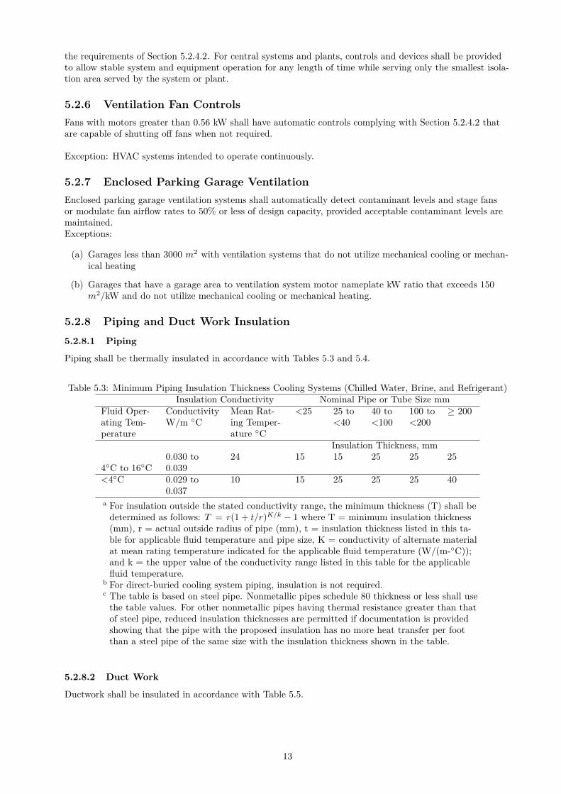
the requirements of Section 5.2.4.2. For central systems and plants, controls and devices shall be providedto allow stable system and equipment operation for any length of time while serving only the smallest isola-tion area served by the system or plant.
5.2.6 Ventilation Fan Controls
Fans with motors greater than 0.56 kW shall have automatic controls complying with Section 5.2.4.2 thatare capable of shutting off fans when not required.
Exception: HVAC systems intended to operate continuously.
5.2.7 Enclosed Parking Garage Ventilation
Enclosed parking garage ventilation systems shall automatically detect contaminant levels and stage fansor modulate fan airflow rates to 50% or less of design capacity, provided acceptable contaminant levels aremaintained.Exceptions:
(a) Garages less than 3000 m2 with ventilation systems that do not utilize mechanical cooling or mechan-ical heating
(b) Garages that have a garage area to ventilation system motor nameplate kW ratio that exceeds 150m2/kW and do not utilize mechanical cooling or mechanical heating.
5.2.8 Piping and Duct Work Insulation
5.2.8.1 Piping
Piping shall be thermally insulated in accordance with Tables 5.3 and 5.4.
Table 5.3: Minimum Piping Insulation Thickness Cooling Systems (Chilled Water, Brine, and Refrigerant)Insulation Conductivity Nominal Pipe or Tube Size mm
Fluid Oper-ating Tem-perature
ConductivityW/m ◦C
Mean Rat-ing Temper-ature ◦C
<25 25 to<40
40 to<100
100 to<200
≥ 200
Insulation Thickness, mm
4◦C to 16◦C0.030 to0.039
24 15 15 25 25 25
<4◦C 0.029 to0.037
10 15 25 25 25 40
a For insulation outside the stated conductivity range, the minimum thickness (T) shall bedetermined as follows: T = r(1 + t/r)K/k − 1 where T = minimum insulation thickness(mm), r = actual outside radius of pipe (mm), t = insulation thickness listed in this ta-ble for applicable fluid temperature and pipe size, K = conductivity of alternate materialat mean rating temperature indicated for the applicable fluid temperature (W/(m-◦C));and k = the upper value of the conductivity range listed in this table for the applicablefluid temperature.
b For direct-buried cooling system piping, insulation is not required.c The table is based on steel pipe. Nonmetallic pipes schedule 80 thickness or less shall use
the table values. For other nonmetallic pipes having thermal resistance greater than thatof steel pipe, reduced insulation thicknesses are permitted if documentation is providedshowing that the pipe with the proposed insulation has no more heat transfer per footthan a steel pipe of the same size with the insulation thickness shown in the table.
5.2.8.2 Duct Work
Ductwork shall be insulated in accordance with Table 5.5.
13
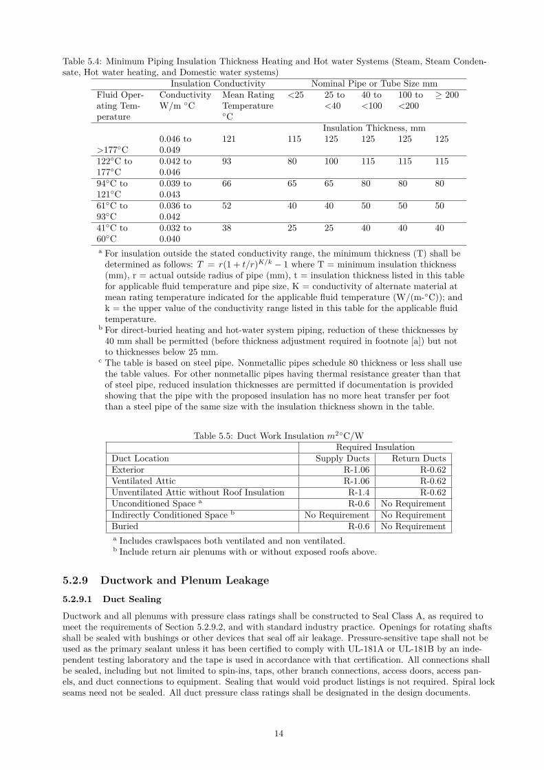
Table 5.4: Minimum Piping Insulation Thickness Heating and Hot water Systems (Steam, Steam Conden-sate, Hot water heating, and Domestic water systems)
Insulation Conductivity Nominal Pipe or Tube Size mmFluid Oper-ating Tem-perature
ConductivityW/m ◦C
Mean RatingTemperature◦C
<25 25 to<40
40 to<100
100 to<200
≥ 200
Insulation Thickness, mm
>177◦C0.046 to0.049
121 115 125 125 125 125
122◦C to177◦C
0.042 to0.046
93 80 100 115 115 115
94◦C to121◦C
0.039 to0.043
66 65 65 80 80 80
61◦C to93◦C
0.036 to0.042
52 40 40 50 50 50
41◦C to60◦C
0.032 to0.040
38 25 25 40 40 40
a For insulation outside the stated conductivity range, the minimum thickness (T) shall bedetermined as follows: T = r(1 + t/r)K/k − 1 where T = minimum insulation thickness(mm), r = actual outside radius of pipe (mm), t = insulation thickness listed in this tablefor applicable fluid temperature and pipe size, K = conductivity of alternate material atmean rating temperature indicated for the applicable fluid temperature (W/(m-◦C)); andk = the upper value of the conductivity range listed in this table for the applicable fluidtemperature.
b For direct-buried heating and hot-water system piping, reduction of these thicknesses by40 mm shall be permitted (before thickness adjustment required in footnote [a]) but notto thicknesses below 25 mm.
c The table is based on steel pipe. Nonmetallic pipes schedule 80 thickness or less shall usethe table values. For other nonmetallic pipes having thermal resistance greater than thatof steel pipe, reduced insulation thicknesses are permitted if documentation is providedshowing that the pipe with the proposed insulation has no more heat transfer per footthan a steel pipe of the same size with the insulation thickness shown in the table.
Table 5.5: Duct Work Insulation m2◦C/WRequired Insulation
Duct Location Supply Ducts Return DuctsExterior R-1.06 R-0.62Ventilated Attic R-1.06 R-0.62Unventilated Attic without Roof Insulation R-1.4 R-0.62Unconditioned Space a R-0.6 No RequirementIndirectly Conditioned Space b No Requirement No RequirementBuried R-0.6 No Requirementa Includes crawlspaces both ventilated and non ventilated.b Include return air plenums with or without exposed roofs above.
5.2.9 Ductwork and Plenum Leakage
5.2.9.1 Duct Sealing
Ductwork and all plenums with pressure class ratings shall be constructed to Seal Class A, as required tomeet the requirements of Section 5.2.9.2, and with standard industry practice. Openings for rotating shaftsshall be sealed with bushings or other devices that seal off air leakage. Pressure-sensitive tape shall not beused as the primary sealant unless it has been certified to comply with UL-181A or UL-181B by an inde-pendent testing laboratory and the tape is used in accordance with that certification. All connections shallbe sealed, including but not limited to spin-ins, taps, other branch connections, access doors, access pan-els, and duct connections to equipment. Sealing that would void product listings is not required. Spiral lockseams need not be sealed. All duct pressure class ratings shall be designated in the design documents.
14
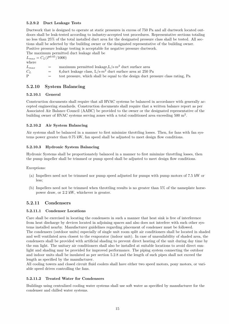
5.2.9.2 Duct Leakage Tests
Ductwork that is designed to operate at static pressures in excess of 750 Pa and all ductwork located out-doors shall be leak-tested according to industry-accepted test procedures. Representative sections totalingno less than 25% of the total installed duct area for the designated pressure class shall be tested. All sec-tions shall be selected by the building owner or the designated representative of the building owner.Positive pressure leakage testing is acceptable for negative pressure ductwork.The maximum permitted duct leakage shall beLmax = CL(P 0.65/1000)whereLmax = maximum permitted leakage,L/s·m2 duct surface areaCL = 6,duct leakage class, L/s·m2 duct surface area at 250 PaP = test pressure, which shall be equal to the design duct pressure class rating, Pa
5.2.10 System Balancing
5.2.10.1 General
Construction documents shall require that all HVAC systems be balanced in accordance with generally ac-cepted engineering standards. Construction documents shall require that a written balance report as perAssociated Air Balance Council (AABC) be provided to the owner or the designated representative of thebuilding owner of HVAC systems serving zones with a total conditioned area exceeding 500 m2.
5.2.10.2 Air System Balancing
Air systems shall be balanced in a manner to first minimize throttling losses. Then, for fans with fan sys-tems power greater than 0.75 kW, fan speed shall be adjusted to meet design flow conditions.
5.2.10.3 Hydronic System Balancing
Hydronic Systems shall be proportionately balanced in a manner to first minimize throttling losses, thenthe pump impeller shall be trimmed or pump speed shall be adjusted to meet design flow conditions.
Exceptions:
(a) Impellers need not be trimmed nor pump speed adjusted for pumps with pump motors of 7.5 kW orless;
(b) Impellers need not be trimmed when throttling results is no greater than 5% of the nameplate horse-power draw, or 2.2 kW, whichever is greater.
5.2.11 Condensers
5.2.11.1 Condenser Locations
Care shall be exercised in locating the condensers in such a manner that heat sink is free of interferencefrom heat discharge by devices located in adjoining spaces and also does not interfere with such other sys-tems installed nearby. Manufacturer guidelines regarding placement of condenser must be followed.The condensers (outdoor units) especially of single unit room split air conditioners shall be located in shadedand well ventilated area closest to the evaporator (indoor unit). In case of unavailability of shaded area, thecondensers shall be provided with artificial shading to prevent direct heating of the unit during day time bythe sun light. The unitary air conditioners shall also be installed at suitable locations to avoid direct sun-light and shading may be provided for improved performance. The piping system connecting the outdoorand indoor units shall be insulated as per section 5.2.8 and the length of such pipes shall not exceed thelength as specified by the manufacturer.All cooling towers and closed circuit fluid coolers shall have either two speed motors, pony motors, or vari-able speed drives controlling the fans.
5.2.11.2 Treated Water for Condensers
Buildings using centralized cooling water systems shall use soft water as specified by manufacturer for thecondenser and chilled water systems.
15
5.2.12 Zone Sealing
The automatic door closure and door gaps sealing arrangement should be provided in all air conditionedrooms.
5.3 Prescriptive Requirements
Compliance shall be demonstrated with the requirements in section 5.3.1 through section 5.3.2 for eachHVAC system.
5.3.1 Fan System Power and Efficiency
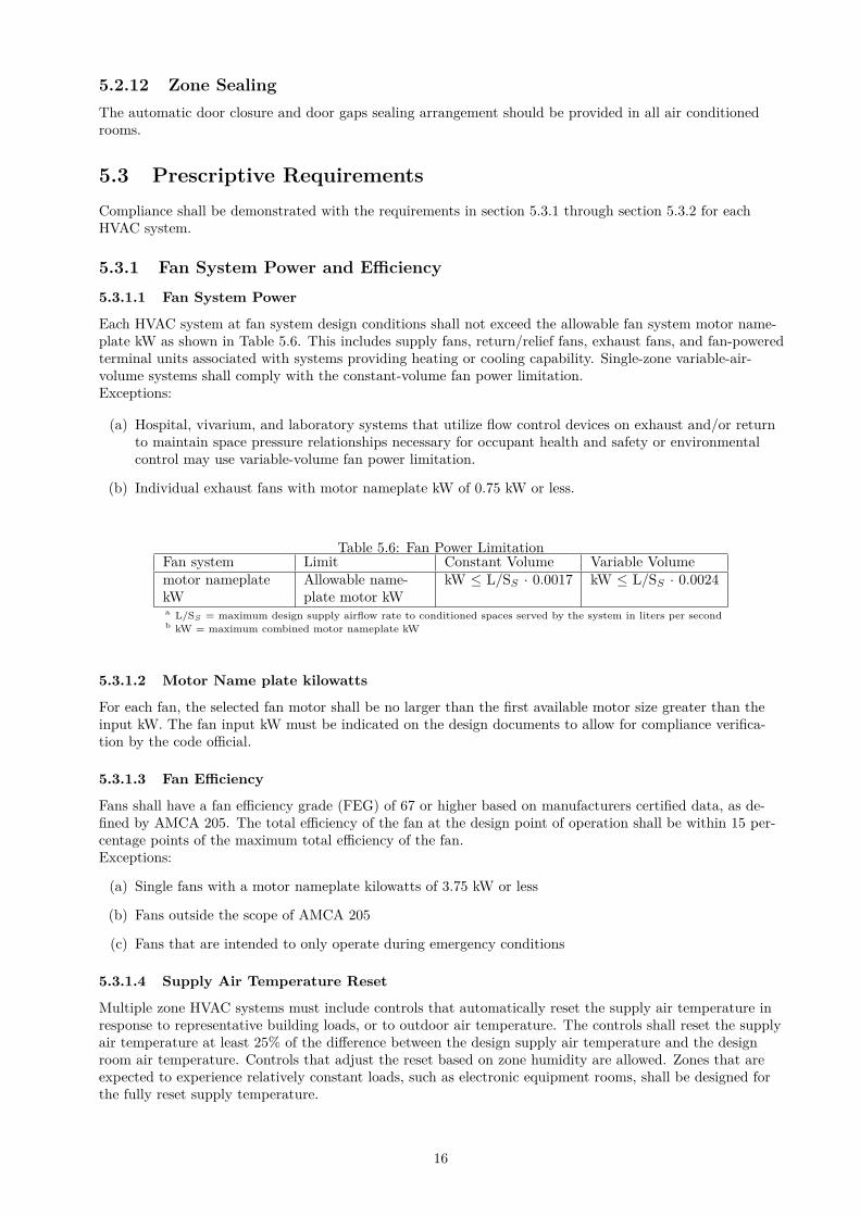
5.3.1.1 Fan System Power
Each HVAC system at fan system design conditions shall not exceed the allowable fan system motor name-plate kW as shown in Table 5.6. This includes supply fans, return/relief fans, exhaust fans, and fan-poweredterminal units associated with systems providing heating or cooling capability. Single-zone variable-air-volume systems shall comply with the constant-volume fan power limitation.Exceptions:
(a) Hospital, vivarium, and laboratory systems that utilize flow control devices on exhaust and/or returnto maintain space pressure relationships necessary for occupant health and safety or environmentalcontrol may use variable-volume fan power limitation.
(b) Individual exhaust fans with motor nameplate kW of 0.75 kW or less.
Table 5.6: Fan Power LimitationFan system Limit Constant Volume Variable Volumemotor nameplatekW
Allowable name-plate motor kW
kW ≤ L/SS · 0.0017 kW ≤ L/SS · 0.0024
a L/SS = maximum design supply airflow rate to conditioned spaces served by the system in liters per secondb kW = maximum combined motor nameplate kW
5.3.1.2 Motor Name plate kilowatts
For each fan, the selected fan motor shall be no larger than the first available motor size greater than theinput kW. The fan input kW must be indicated on the design documents to allow for compliance verifica-tion by the code official.
5.3.1.3 Fan Efficiency
Fans shall have a fan efficiency grade (FEG) of 67 or higher based on manufacturers certified data, as de-fined by AMCA 205. The total efficiency of the fan at the design point of operation shall be within 15 per-centage points of the maximum total efficiency of the fan.Exceptions:
(a) Single fans with a motor nameplate kilowatts of 3.75 kW or less
(b) Fans outside the scope of AMCA 205
(c) Fans that are intended to only operate during emergency conditions
5.3.1.4 Supply Air Temperature Reset
Multiple zone HVAC systems must include controls that automatically reset the supply air temperature inresponse to representative building loads, or to outdoor air temperature. The controls shall reset the supplyair temperature at least 25% of the difference between the design supply air temperature and the designroom air temperature. Controls that adjust the reset based on zone humidity are allowed. Zones that areexpected to experience relatively constant loads, such as electronic equipment rooms, shall be designed forthe fully reset supply temperature.
16
5.3.1.5 Fan Control
DX cooling system with mechanical cooling capacity ≥ 19 kW and chilled-water cooling system having fanmotor size ≥ 0.75 kW shall be designed to vary the indoor fan airflow as a function of load and shall com-ply with the following requirements:
(a) DX and chilled-water cooling units that control the capacity of the mechanical cooling directly basedon space temperature shall have a minimum of two stages of fan control. Low or minimum speed shallnot exceed 66% of full speed. At low or minimum speed, the fan system shall draw no more than 40%of the fan power at full fan speed. Low or minimum speed shall be used during periods of low coolingload and ventilation-only operation.
(b) All other units, including DX cooling units and chilled water units that control the space tempera-ture by modulating the airflow to the space, shall have modulating fan control. Minimum speed shallnot exceed 50% of full speed. At minimum speed, the fan system shall draw no more than 30% of thepower at full fan speed. Low or minimum speed shall be used during periods of low cooling load andventilation-only operation.
5.3.2 Variable Flow Hydronic Systems
5.3.2.1
Chilled or hot-water systems shall be designed for variable fluid flow and shall be capable of reducing pumpflow rates to not more than the larger of:
(a) 50% of the design flow rate; or
(b) The minimum flow required by the equipment manufacturer for proper operation of the chiller or boil-ers.
5.3.2.2
Water cooled air conditioning or heat pump units with a circulation pump motor greater than or equal to3.7 kW shall have two way automatic isolation valves on each water cooled air conditioning or heat pumpunit that are interlocked with the compressor to shutoff condenser water flow when the compressor is notoperating.
5.3.2.3
Chilled Water and Condensor Water pump power Chilled water or condenser water systems that must com-ply with either section 5.3.2.1 or section 5.3.2.2 and that have pump motors greater than or equal to 3.7kW shall be controlled by variable speed drives.
5.3.2.4 Chilled Water and Condenser Water Pump Power
The design chilled water pump power shall be less than or equal to 350 kW/1000 L/s. Chilled-water sys-tems serving air conditioned area of 11,000 m2 or more shall have primary/secondary systems with variable-speed drives on the secondary pumping loop. Chilled-water pumps in systems serving less than 11,000 m2
cooling capacity shall have primary/secondary systems with secondary pump riding the pump curve. Thedesign condenser-water pump power shall be less than or equal to 310 kW/1000 L/s.
5.3.2.5 Heat Rejection Equipment
The fan system on a heat rejection device powered by an individual motor or array of motors with a con-nected power, including the motor service factor, totaling 3.8 kW or more shall have controls and/or de-vices (such as variable speed control) that shall result in fan motor demand or no more than 30% of designwattage at 50% of the design air flow and that shall automatically modulate the fan speed to control theleaving fluid temperature or condensing temperature/pressure or the heat rejection device.Exceptions:
(a) Condenser fans serving multiple refrigerant circuits
(b) Condenser fans serving flooded condensers
17
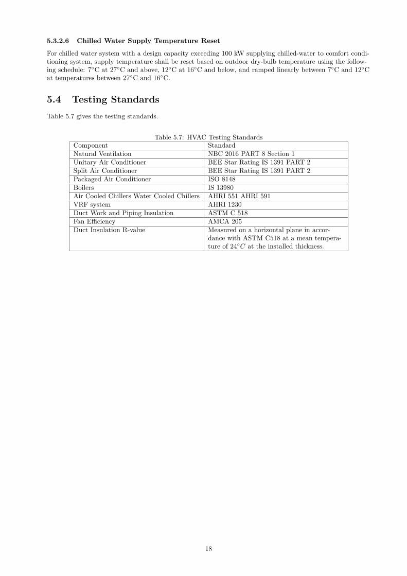
5.3.2.6 Chilled Water Supply Temperature Reset
For chilled water system with a design capacity exceeding 100 kW supplying chilled-water to comfort condi-tioning system, supply temperature shall be reset based on outdoor dry-bulb temperature using the follow-ing schedule: 7◦C at 27◦C and above, 12◦C at 16◦C and below, and ramped linearly between 7◦C and 12◦Cat temperatures between 27◦C and 16◦C.
5.4 Testing Standards
Table 5.7 gives the testing standards.
Table 5.7: HVAC Testing StandardsComponent StandardNatural Ventilation NBC 2016 PART 8 Section 1Unitary Air Conditioner BEE Star Rating IS 1391 PART 2Split Air Conditioner BEE Star Rating IS 1391 PART 2Packaged Air Conditioner ISO 8148Boilers IS 13980Air Cooled Chillers Water Cooled Chillers AHRI 551 AHRI 591VRF system AHRI 1230Duct Work and Piping Insulation ASTM C 518Fan Efficiency AMCA 205Duct Insulation R-value Measured on a horizontal plane in accor-
dance with ASTM C518 at a mean tempera-ture of 24◦C at the installed thickness.
18
6 Service Hot Water and Pumping
6.1 General
All service water heating equipment and system shall comply with the mandatory provisions of section 6.2.All service hot water and pumping components shall be tested as per the provisions given in section 6.4.
6.2 Mandatory Requirements
6.2.1 Load Calculation
Service water heating system design loads for the purpose of sizing systems and equipment shall be deter-mined in accordance with manufacturers published sizing guidelines or generally accepted engineering stan-dards and handbooks acceptable to the adopting authority e.g. ASHRAE Handbook: HVAC Applications.
6.2.2 Solar Water Heating
Commercial establishments like Hotels, Hospitals, and Guest houses with a centralized system shall havesolar water heating for at least 1/5 of the design capacity:Exception to section 6.2.2: systems that use heat recovery for at least 1/5 of the design capacity.
6.2.3 Equipment Efficiency
Service water heating equipment shall meet or exceed the performance and minimum efficiency requirementpresented in available Indian Standards.
(a) Solar water heater shall meet the performance/minimum efficiency level mentioned in IS 13129 Part(1 and 2)
(b) Gas Instantaneous Water heater shall meet the performance/minimum efficiency level mentioned in IS15558 with above 80% thermal efficiency; and
(c) Electric water heater shall meet the performance /minimum efficiency level mentioned in IS 2082.
6.2.4 Supplementary Water Heating System
Supplementary water heating system shall be designed to maximize the energy efficiency of the system andshall incorporate the following design features in cascade:
(a) Maximum heat recovery from hot discharge system like condensers of air conditioning units;
(b) Use of gas fired heaters wherever gas is available; and
(c) Electric heater as last resort.
6.2.5 Piping Insulation
Piping insulation shall comply with section 5.2.8.1. The entire hot water system including the storage tanks,pipelines shall be insulated conforming to the relevant IS standards on materials and applications.
6.2.6 Heat Traps
Vertical pipe risers serving storage water heaters and storage tanks not having integral heat traps and serv-ing a non-recirculating system shall have heat traps on both the inlet and outlet piping as close as practicalto the storage tank.
19
6.2.7 Swimming Pools
Heated pools shall be provided with a vapor retardant pool cover on or at the water surface. Pools heatedto more than 32◦C shall have a pool cover with a minimum insulation value of R-2.1:Exception to section 6.2.7: Pools deriving over 60% of their energy from site- recovered energy or solar en-ergy source.
6.2.8 Compliance Documentation
The application for approval shall furnish detailed calculation showing the design to ensure that at least20% of the heating requirement shall be met from solar heat/ heat recovery and not more than 80% of theheat shall be met from electrical heating. Wherever gas is available, not more than 20% of the heat shall bemet from electrical heating.
6.3 Prescriptive Requirements
There is no prescriptive requirement in this section.
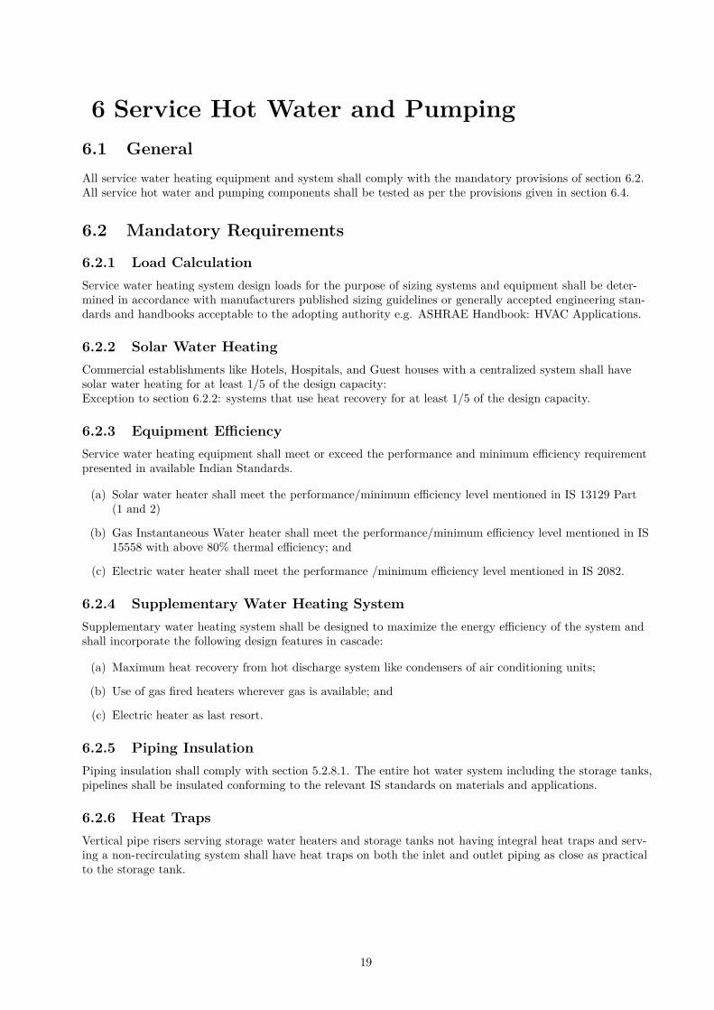
6.4 Testing Standards
Table 6.1 gives the testing standards.
Table 6.1: Testing StandardComponent StandardSolar Water Heater IS 13129 Part 1 and 2Gas Instantaneous Water Heater IS 15558Electric Water Heater IS 2082
20
7 Lighting
7.1 General
Lighting systems and equipment shall comply with the mandatory provisions of section 7.2 and the pre-scriptive criteria of section 7.3. All lighting components shall be tested as per the provisions given in sec-tion 7.4.The lighting requirements in this section shall apply to:
(a) Interior spaces of buildings;
(b) Exterior building features, including facades, illuminated roofs, architectural features, entrances, exits,loading docks, and illuminated canopies; and
(c) Exterior building grounds lighting that is provided through the buildings electrical service
Exception to 7.1: Emergency lighting that is automatically off during normal building operation and ispowered by battery, generator, or other alternate power source.
7.2 Mandatory Requirements
7.2.1 Interior Lighting Control
7.2.1.1 Local Control
There shall be one or more manual lighting controls in each enclosed space that controls all of the lightingin the space. Each control device shall control an area no larger than 250 m2. The device installed to com-ply with this provision shall be readily accessible and located so that the occupants can see the controlledlighting when using the control device.
Exception: Remote location of this local control device or devices shall be permitted for reasons of safetyor security when each remote control device has an indicator pilot light as part of or next to the control de-vice and the light is clearly labeled to identify the controlled lighting.
7.2.1.2 Partial Automatic ON
No more than 25% of the lighting power for the general lighting shall be allowed to be automatically turnedon.
Exception: Toilets, stairs, and corridors.
7.2.1.3 Bilevel Lighting Control
The general lighting in the space shall be controlled so as to provide at least one intermediate step in light-ing power or continuous dimming in addition to full ON and full OFF. At least one intermediate step shallbe between 30% and 70% (inclusive) of full lighting power.
Exception: Corridors and lobby.
7.2.1.4 Automatic Daylight Responsive Controls for Sidelighting/Toplighting
In any space where the combined input power of all general lighting completely or partially within the pri-mary sidelighted/toplighting areas is more than 50% power required by Table 7.1/7.2, the general lightingin the primary sidelighted/toplighting areas shall be controlled by photocontrols.
7.2.1.5 Automatic Full OFF
All lighting shall be automatically shut off within 20 minutes of all occupants leaving the space. A controldevice meeting this requirement shall control no more than 250 m2.
Exceptions: The following lighting is not required to be automatically shut off:
21
(a) General lighting and task lighting in shop and laboratory classrooms
(b) General lighting and task lighting in spaces where automatic shutoff would endanger the safety or se-curity of room or building occupants
7.2.2 Parking Garage Lighting Control
Lighting power of each luminaire shall be automatically reduced by a minimum of 30% when there is no ac-tivity detected within a lighting zone for 20 minutes. Lighting zones for this requirement shall be no largerthan 500 m2.
7.2.3 Exterior Lighting Control
Lighting for all exterior applications not exempted in section 7.3.5 of the code shall be controlled by a photosensor or astronomical time switch that is capable of automatically turning off the exterior lighting whendaylight is available or the lighting is not required. All building façade and landscape lighting shall be au-tomatically shut off from midnight or business closing whichever is later. If the business starts before 7 AMthen the lights can again turned on at the start of business.
7.2.4 Additional Control
The following lighting applications shall be equipped with a control device to control such lighting indepen-dently of general lighting,-
(a) Display/ Accent Lighting: Display or accent lighting greater than 300 m2 area shall have a separatecontrol device;
(b) Case Lighting: in cases used for display purposes greater than 300 m2 areas shall be equipped with aseparate control device;
(c) Hotel and Motel Guest Room Lighting: Hotel and motel guest rooms and guest suites shall have amaster control device at the main room entry that controls all permanently installed luminaries andswitched receptacles;
(d) Task Lighting: Supplemental task lighting including permanently installed under shelf or under cabi-net lighting shall have a control device integral to the luminaires or controlled by a wall mounted con-trol device provided the control device complies with section 7.2.1.
(e) Non-visual Lighting: Lighting for non-visual applications, such as plant growth and food-warming,shall be equipped with a separate control device; and
(f) Demonstration Lighting: Lighting equipment that is for sale or for demonstrations in lighting educa-tion shall be equipped with separate control device accessible only to authorized personnel.
7.2.5 Signage/Advertising Signage
Internally illuminated exit signs shall not exceed 5 W per face. The lighting power density in case of sig-nage/advertisement signage should not exceed 50 W/m2 for internally illuminated signage and 25 W/m2
for externally illuminated signage.
7.2.6 Exterior Building Grounds Lighting
Luminaires for exterior building grounds lighting that operate at greater than 100 W shall contain lampshaving minimum efficacy of 80 lm/W unless the luminaire is controlled by a motion sensor or exempt undersection 7.1.
7.3 Prescriptive Requirements
7.3.1 Interior Lighting Power
The installed interior lighting power for a building or a separately metered or permitted portion of a build-ing shall be calculated in accordance with section 7.3.4 and shall not exceed the interior lighting power al-lowance determined in accordance with either section
22
Exception for 7.3.1: The following lighting equipment and application shall not be considered when deter-mining the interior lighting power allowance, nor shall the wattage for such lighting be included in the in-stalled interior lighting power. However, any such lighting shall not be exempt unless it is an addition togeneral lighting and is controlled by an independent control device,-
(a) Display or accent lighting that is an essential element for the function performed in galleries, muse-ums, and monuments;
(b) Lighting that is integral to equipment or instrumentation and is installed by its manufacturer;
(c) Lighting specifically designed for medical or dental procedures and lighting integral to medical equip-ment;
(d) Lighting integral to food warming and food preparation equipment;
(e) Lighting for plant growth or maintenance;
(f) Lighting in spaces specifically designed for use by the visually impaired;
(g) Lighting in retail display windows, provided the display area is enclosed by ceiling-height partitions;
(h) Lighting in interior spaces that have been specifically designated as a registered interior historic land-mark;
(i) Lighting that is an integral part of advertising or directional signage;
(j) Exit signs;
(k) Lighting that is for sale or lighting educational demonstration systems;
(l) Lighting for theatrical purposes, including performance, stage, and film or video production;
(m) Athletic playing areas with permanent facilities for television broadcasting.
7.3.2 Building Area Method
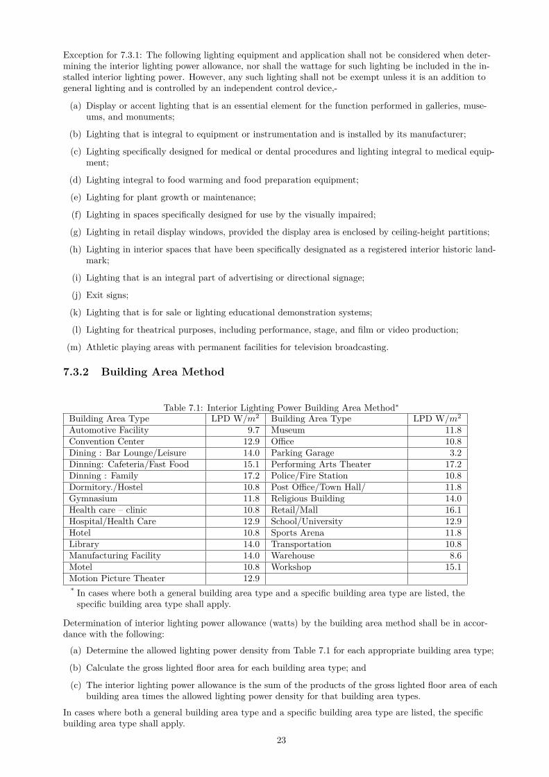
Table 7.1: Interior Lighting Power Building Area Method∗
Building Area Type LPD W/m2 Building Area Type LPD W/m2
Automotive Facility 9.7 Museum 11.8Convention Center 12.9 Office 10.8Dining : Bar Lounge/Leisure 14.0 Parking Garage 3.2Dinning: Cafeteria/Fast Food 15.1 Performing Arts Theater 17.2Dinning : Family 17.2 Police/Fire Station 10.8Dormitory./Hostel 10.8 Post Office/Town Hall/ 11.8Gymnasium 11.8 Religious Building 14.0Health care – clinic 10.8 Retail/Mall 16.1Hospital/Health Care 12.9 School/University 12.9Hotel 10.8 Sports Arena 11.8Library 14.0 Transportation 10.8Manufacturing Facility 14.0 Warehouse 8.6Motel 10.8 Workshop 15.1Motion Picture Theater 12.9* In cases where both a general building area type and a specific building area type are listed, the
specific building area type shall apply.
Determination of interior lighting power allowance (watts) by the building area method shall be in accor-dance with the following:
(a) Determine the allowed lighting power density from Table 7.1 for each appropriate building area type;
(b) Calculate the gross lighted floor area for each building area type; and
(c) The interior lighting power allowance is the sum of the products of the gross lighted floor area of eachbuilding area times the allowed lighting power density for that building area types.
In cases where both a general building area type and a specific building area type are listed, the specificbuilding area type shall apply.
23
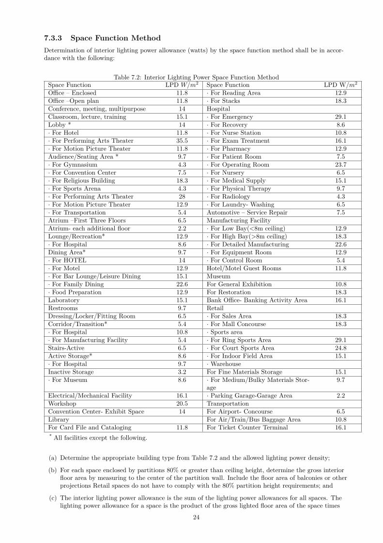
7.3.3 Space Function Method
Determination of interior lighting power allowance (watts) by the space function method shall be in accor-dance with the following:
Table 7.2: Interior Lighting Power Space Function MethodSpace Function LPD W/m2 Space Function LPD W/m2
Office – Enclosed 11.8 · For Reading Area 12.9Office –Open plan 11.8 · For Stacks 18.3Conference, meeting, multipurpose 14 HospitalClassroom, lecture, training 15.1 · For Emergency 29.1Lobby * 14 · For Recovery 8.6· For Hotel 11.8 · For Nurse Station 10.8· For Performing Arts Theater 35.5 · For Exam Treatment 16.1· For Motion Picture Theater 11.8 · For Pharmacy 12.9Audience/Seating Area * 9.7 · For Patient Room 7.5· For Gymnasium 4.3 · For Operating Room 23.7· For Convention Center 7.5 · For Nursery 6.5· For Religious Building 18.3 · For Medical Supply 15.1· For Sports Arena 4.3 · For Physical Therapy 9.7· For Performing Arts Theater 28 · For Radiology 4.3· For Motion Picture Theater 12.9 · For Laundry- Washing 6.5· For Transportation 5.4 Automotive – Service Repair 7.5Atrium –First Three Floors 6.5 Manufacturing FacilityAtrium- each additional floor 2.2 · For Low Bay(<8m ceiling) 12.9Lounge/Recreation* 12.9 · For High Bay(>8m ceiling) 18.3· For Hospital 8.6 · For Detailed Manufacturing 22.6Dining Area* 9.7 · For Equipment Room 12.9· For HOTEL 14 · For Control Room 5.4· For Motel 12.9 Hotel/Motel Guest Rooms 11.8· For Bar Lounge/Leisure Dining 15.1 Museum· For Family Dining 22.6 For General Exhibition 10.8· Food Preparation 12.9 For Restoration 18.3Laboratory 15.1 Bank Office- Banking Activity Area 16.1Restrooms 9.7 RetailDressing/Locker/Fitting Room 6.5 · For Sales Area 18.3Corridor/Transition* 5.4 · For Mall Concourse 18.3· For Hospital 10.8 · Sports area· For Manufacturing Facility 5.4 · For Ring Sports Area 29.1Stairs-Active 6.5 · For Court Sports Area 24.8Active Storage* 8.6 · For Indoor Field Area 15.1· For Hospital 9.7 · WarehouseInactive Storage 3.2 For Fine Materials Storage 15.1· For Museum 8.6 · For Medium/Bulky Materials Stor-
age9.7
Electrical/Mechanical Facility 16.1 · Parking Garage-Garage Area 2.2Workshop 20.5 TransportationConvention Center- Exhibit Space 14 For Airport- Concourse 6.5Library For Air/Train/Bus Baggage Area 10.8For Card File and Cataloging 11.8 For Ticket Counter Terminal 16.1* All facilities except the following.
(a) Determine the appropriate building type from Table 7.2 and the allowed lighting power density;
(b) For each space enclosed by partitions 80% or greater than ceiling height, determine the gross interiorfloor area by measuring to the center of the partition wall. Include the floor area of balconies or otherprojections Retail spaces do not have to comply with the 80% partition height requirements; and
(c) The interior lighting power allowance is the sum of the lighting power allowances for all spaces. Thelighting power allowance for a space is the product of the gross lighted floor area of the space times
24
the allowed lighting power density for that space.
7.3.4 Installed Interior Lighting Power
The installed interior lighting power calculated for compliance with section 7.3 shall include all power usedby the luminaries, including lamps, ballasts, current regulators, and control devices except as specificallyexempted in section 7.1:Exception to section 7.3.4: If two or more independently operating lighting systems in a space are con-trolled to prevent simultaneous user operation, the installed interior lighting power shall be based solelyon the lighting system with the highest power.
7.3.4.1 Luminaire Wattage
Luminaire wattage incorporated into the installed interior lighting power shall be determined in accordancewith the following,-
(a) The wattage of incandescent luminaries with medium base sockets and not containing permanentlyinstalled ballasts shall be the maximum labeled wattage of the luminaries;
(b) The wattage of luminaires containing permanently installed ballasts shall be the operating input wattageof the specified lamp/ ballast combination based on values from manufacturers catalogs or valuesfrom independent testing laboratory reports;
(c) The wattage of all other miscellaneous luminaire types not described in (a) or (b) shall be the speci-fied wattage of the luminaires; and
(d) The wattage of lighting track, plug-in bus way, and flexible lighting systems that allow the additionand/ or relocation of luminaries without altering the wiring of the system shall be the larger of thespecified wattage of the luminaires included in the system or 135 W/m. Systems with integral over-load protection such as fuses or circuit breakers shall be rated at 100% of the maximum rated load ofthe limiting device.
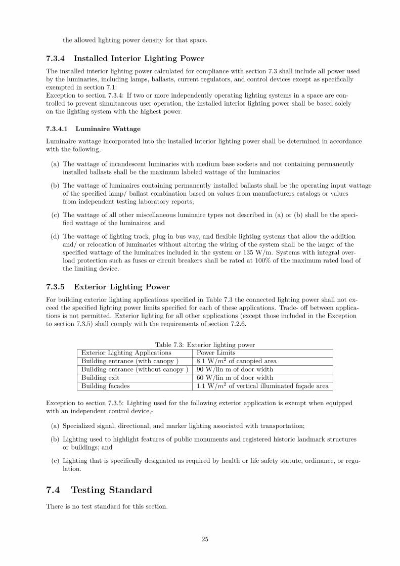
7.3.5 Exterior Lighting Power
For building exterior lighting applications specified in Table 7.3 the connected lighting power shall not ex-ceed the specified lighting power limits specified for each of these applications. Trade- off between applica-tions is not permitted. Exterior lighting for all other applications (except those included in the Exceptionto section 7.3.5) shall comply with the requirements of section 7.2.6.
Table 7.3: Exterior lighting powerExterior Lighting Applications Power LimitsBuilding entrance (with canopy ) 8.1 W/m2 of canopied areaBuilding entrance (without canopy ) 90 W/lin m of door widthBuilding exit 60 W/lin m of door widthBuilding facades 1.1 W/m2 of vertical illuminated façade area
Exception to section 7.3.5: Lighting used for the following exterior application is exempt when equippedwith an independent control device,-
(a) Specialized signal, directional, and marker lighting associated with transportation;
(b) Lighting used to highlight features of public monuments and registered historic landmark structuresor buildings; and
(c) Lighting that is specifically designated as required by health or life safety statute, ordinance, or regu-lation.
7.4 Testing Standard
There is no test standard for this section.
25
8 Electrical Power
8.1 General
Electrical equipment and systems shall comply with the mandatory requirements of section 8.2. All electri-cal equipment and systems shall be tested as per the provisions given in section 8.4.
8.2 Mandatory Requirements
8.2.1 Transformers
8.2.1.1 Maximum Allowable Distribution Transformer Losses
Distribution transformers of the proper ratings and design must be selected to satisfy the minimum accept-able efficiency at 50% and full load rating.Total losses for oil filled transformers shall meet IS 1180. Total losses for dry transformers should conformas per the standard of Indian Standard IS 2026: Part 11 2007.
8.2.1.2 Measurement and Reporting of Transformer Losses
All measurement of losses shall be carried out by using calibrated digital meters of class 0.5 or better ac-curacy and certified by the manufacturer. All transformers of capacity of 500 kVA and above would beequipped with additional metering class current transformers (CTs) and potential transformers (PTs) ad-ditional to requirements of utilities so that periodic loss monitoring study may be carried out.
8.2.2 Energy Efficient Motors
Motors shall comply with the following:
(a) All permanently wired polyphase motors of 0.375 kW or more serving the building shall have a mini-mum acceptable nominal full load motor efficiency not less than IS 12615 for energy efficient motors;
(b) Motor horsepower ratings shall not exceed 20% of the calculated maximum load being served;
(c) Motor nameplates shall list the nominal full-load motor efficiencies and the full- load power factor;
8.2.3 Power Factor Correction
All electricity supplies exceeding 100 A, 3 phases shall maintain their power factor between 0.95 lag andunity at the point of connection.
8.2.4 Check- Metering and Monitoring
(a) All services exceeding 1000 kVA shall have permanently installed metering to record demand (kVA),energy (kWh), and total power factor. The metering shall also display current (in each phase and theneutral), voltage (between phases and between each phase and neutral), and Total Harmonic Distor-tion (THD) as a percentage of total current.
(b) All services not exceeding 1000 kVA but over 65 KVA shall have permanently installed electric meter-ing to record demand (kVA), energy (kWh), and total power Factor (or kVARh).
(c) All services not exceeding 65 kVA shall have permanently installed electrical metering to record en-ergy (kWh).
(d) Measurement devices shall be installed in new buildings to monitor the electrical energy use for eachof the following separately:
• Total electrical energy
• HVAC systems
• Interior lighting
26
• Exterior lighting
• Receptacle circuits
Recording and Reporting. The electrical energy usage for all loads specified in this section shall be recordeda minimum of every 15 minutes and reported at least hourly, daily, monthly, and annually. The data foreach tenant space shall be made available to that tenant. The system shall be capable of maintaining alldata collected for a minimum of 36 months.
8.2.5 Power Distribution Systems in Buildings
8.2.5.1 Power Distribution System Losses
The Power cabling shall be adequately sized as to maintain the building power distribution losses not toexceed 1% of the total power usage. Record of design calculation for the losses shall be maintained.
8.2.6 Automatic Receptacle Control
The following shall be automatically controlled:
(a) At least 50% of all 220 volt 5 and 10 amp receptacles in all private offices, conference rooms, roomsused primarily for printing and/or copying functions, break rooms, classrooms, and individual work-stations
(b) At least 25% of branch circuit feeders installed for modular furniture not shown on the constructiondocuments
This control shall function on any of the following:
• a scheduled basis using a time of day operated control device that turns receptacles off at specificprogrammed times an independent program schedule shall be provided for controlled areas of nomore than 500 m2 and not more than one floor (the occupant shall be able to manually overridethe control device for up to two hours),
• an occupant sensor that shall turn receptacles off within 20 minutes of all occupants leaving aspace, or
• an automated signal from another control or alarm system that shall turn receptacles off within20 minutes after determining that the area is unoccupied.
All controlled receptacles shall be permanently marked to visually differentiate them from uncontrolled re-ceptacles and are to be uniformly distributed throughout the space.Exceptions: Receptacles for the following shall not require an automatic control device:
(a) Receptacles specifically designated for equipment requiring continuous operation (24 hours/day, 365days/year)
(b) Spaces where an automatic control would endanger the safety or security of the room or building oc-cupant(s).
8.3 Prescriptive Requirement
There is no prescriptive requirements.
8.4 Testing Standard
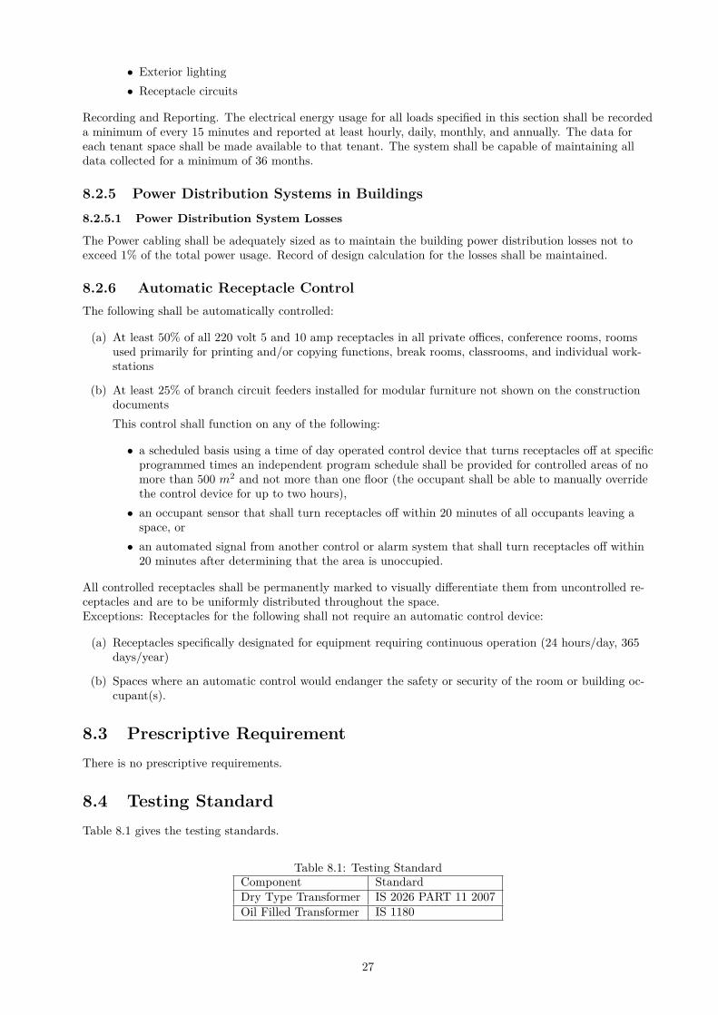
Table 8.1 gives the testing standards.
Table 8.1: Testing StandardComponent StandardDry Type Transformer IS 2026 PART 11 2007
Oil Filled Transformer IS 1180
27

Appendix A: Definitions, Abbreviations and Acronyms
1.1 General:
Certain terms, abbreviations and acronyms are defined in this section for the
purposes of this code. These definitions are applicable to all sections of this
code. Terms that are not defined shall have their ordinarily accepted meanings
within the context in hi h they are used. We ster’s Third Ne International Dictionary of the English Language, Unabridged, copyright 1986, shall be
considered as providing ordinarily accepted meanings.
1.2 Definitions:
"Additio : an extension or increase in floor area or height of a building outside
of the existing building envelope;
"Alteratio : any change, rearrangement, replacement, or addition to a building
or its system and equipment; any modification in construction or building
equipment;
"Annual fuel utilization efficie AFUE : an efficiency description of the ratio
of annual output energy to annual input energy as developed in accordance with
requirements of U.S. Department of Energy (DOE) 10 CFR Part 430;
"Area”: see roof and all, onditioned floor, day lighted, façade, fenestration,
lighted floor
"Astro o i al ti e s it h : an automatic time switch that makes an
adjustment for the length of the day as it varies over the year;
"Authority having jurisdiction : the Authority responsible for enforcing this
code;
"Auto ati : self-acting, operating by its own mechanism, when actuated by
some non-manual influence, such as a change in current strength, pressure,
temperature, or mechanical configuration;
"Auto ati o trol de i e : a device capable of automatically turning loads off
and on without manual intervention;
"Bala i g, air s ste : adjusting airflow rates through air distribution system
devices, such as fans and diffusers, by manually adjusting the position of
dampers, splitters vanes, extractors, etc., or byusing automatic control devices,
such as constant air volume or variable air volume boxes;
"Bala i g, h dro i s ste : adjusting water flow rates through hydronic
distribution system devices, such as pumps and coils, by manually adjusting the
position valves, or by using automatic control devices, such as automatic flow
control valves;
"Ballast : a device used in conjunction with an electric-discharge lamp to cause
the lamp to start and operate under proper circuit conations of voltage, current,
waveform, electrode heat, etc.
"Boiler : a self-contained low-pressure appliance for supplying steam or hot
water;
"Boiler, pa kaged : a boiler that is shipped complete with heating equipment,
mechanical draft equipment, and automatic controls; usually shipped in one or
more sections. A packaged boiler includes factory-built boilers manufactured as
a unit or system, disassembled for shipment, and reassembled at the site;
"Buildi g : a structure wholly or partially enclosed within exterior walls, or
within exterior and party walls, and a roof, affording shelter to persons, animals,
or property;
"Buildi g, e isti g : a building or portion thereof that was previously occupied
or approved for occupancy by the authority having jurisdiction;
2
"Buildi g o ple : a group of buildings in a contiguous area under single
ownership;
"Buildi g e tra e : any doorway, set of doors, turnstiles, or other form of
portal that is ordinarily used to gain access to the building by its users and
occupants.
"Buildi g e elope : the exterior plus the semi-exterior portions of a building.
For the purposes of determining building envelope requirements, the
classifications are defined as follows:
a) Building envelope exterior: the elements of a building that separate
conditioned spaces from the exterior.
b) Building envelope semi-exterior: the elements of a building that
separate conditioned space from unconditioned space or that encloses
semi-heated spaces through which thermal energy may betransferred to
or from the exterior, or to or from unconditioned spaces, or to or from
conditioned spaces;
"Buildi g e it : any doorway, set of doors, or other form of portal that is
ordinarily used only for emergency egress or convenience exit;
"Buildi g grou ds lighti g : lighting pro ided through a uilding’s ele trical
service for parking lot, site, roadway, pedestrian pathway, loading dock, and
security applications;
"Building material": any element of the building envelope through which heat
flows and that heat is included in the component U -factor calculations other
than air films and insulation;
"Cir uit reaker : a device designed to open and close a circuit by non automatic
means and to open the circuit automatically at a predetermined over current
without damage to itself when properly applied within its rating;
"Class of o stru tio :, for the building envelope, a subcategory of roof, wall,
floor slab-on-grade floor, opaque door, vertical fenestration, or skylight;
"Coefficient of performance (COP)- ooli g the ratio of the rate of heat removal
to the rate of energy input, in consistent units, for a complete refrigerating
system or some specific portion of that system under designated operating
conditions;
"Coefficient of performance (COP)-heati g : the ratio of the rate of heat
delivered to the rate of energy input, in consistent units, for a complete heat
pump system including the compressor and, if applicable, auxiliary heat, under
designated operating conditions;
"Co er ial uildi g : all buildings except for multi-family buildings of three
stories or fewer above grade and single-family buildings;
"Co stru tio do u e ts : the drawings and specifications used to construct a
building, building system, or portions thereof;
"Control":to regulate the operation of equipment;
"Co trol de i e : a specialized device used to regulate the operation of
equipment;
"Cool roof : a property of a surface that describes its ability to reflect and reject
heat. Cool roof surfaces have both a light colour (high solar reflectance) and a
high emittance (can reject heat back to the environment);
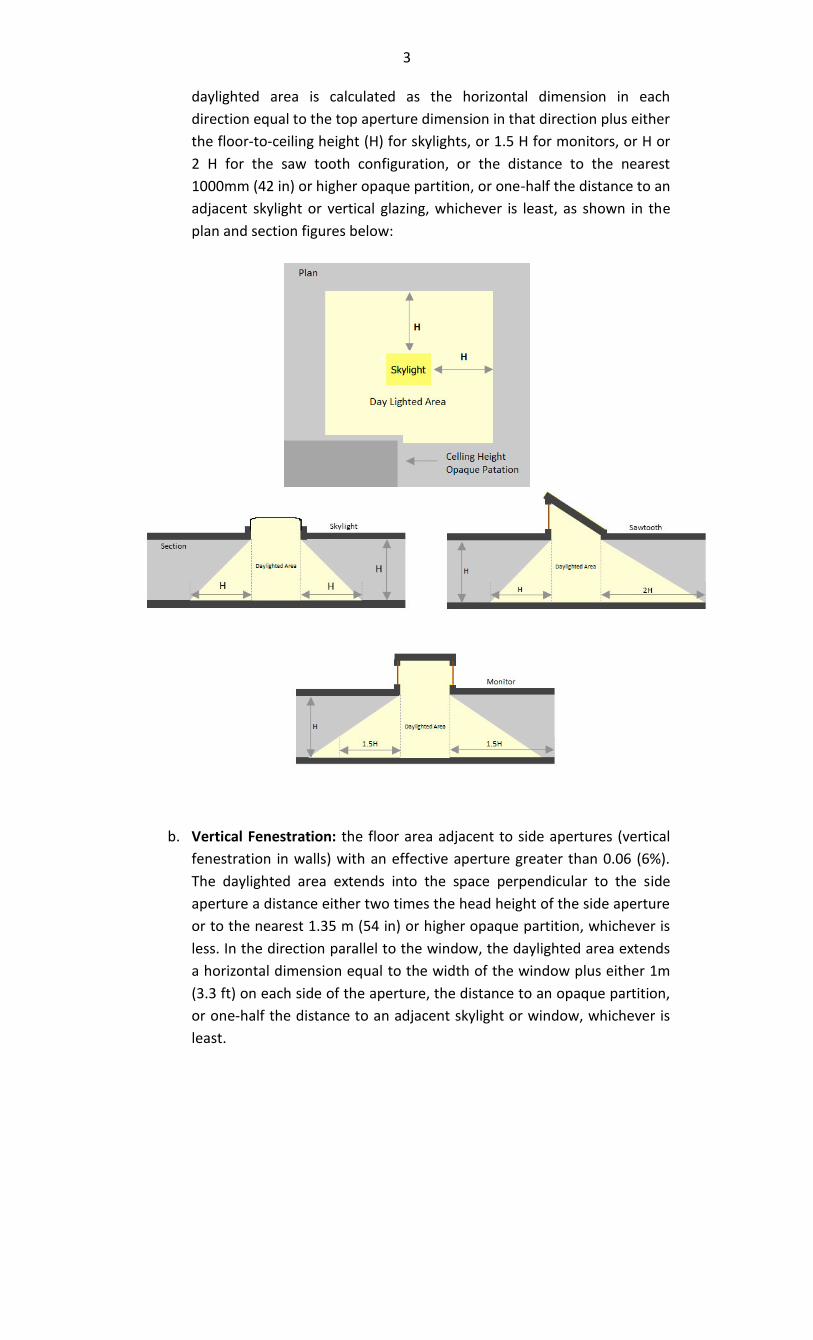
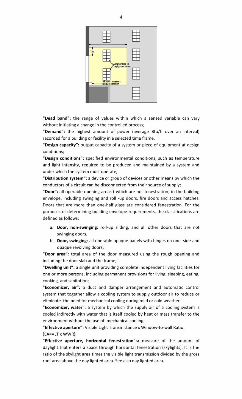
"Daylighted area": the daylight illuminated floor area under horizontal
fenestration (skylight) or adjacent to vertical fenestration (window), described as
follows:
a. Horizontal fenestration: the area under a skylight, monitor, or sawtooth
configuration with an effective aperture greater than 0.001 (0.1% ). The
3
daylighted area is calculated as the horizontal dimension in each
direction equal to the top aperture dimension in that direction plus either
the floor-to-ceiling height (H) for skylights, or 1.5 H for monitors, or H or
2 H for the saw tooth configuration, or the distance to the nearest
1000mm (42 in) or higher opaque partition, or one-half the distance to an
adjacent skylight or vertical glazing, whichever is least, as shown in the
plan and section figures below:
b. Vertical Fenestration: the floor area adjacent to side apertures (vertical
fenestration in walls) with an effective aperture greater than 0.06 (6%).
The daylighted area extends into the space perpendicular to the side
aperture a distance either two times the head height of the side aperture
or to the nearest 1.35 m (54 in) or higher opaque partition, whichever is
less. In the direction parallel to the window, the daylighted area extends
a horizontal dimension equal to the width of the window plus either 1m
(3.3 ft) on each side of the aperture, the distance to an opaque partition,
or one-half the distance to an adjacent skylight or window, whichever is
least.
4
"Dead band": the range of values within which a sensed variable can vary
without initiating a change in the controlled process;
"De a d : the highest amount of power (average Btu/h over an interval)
recorded for a building or facility in a selected time frame.
"Desig apa it : output capacity of a system or piece of equipment at design
conditions;
"Design conditions": specified environmental conditions, such as temperature
and light intensity, required to be produced and maintained by a system and
under which the system must operate;
"Distri utio s ste : a device or group of devices or other means by which the
conductors of a circuit can be disconnected from their source of supply;
"Door : all operable opening areas ( which are not fenestration) in the building
envelope, including swinging and roll -up doors, fire doors and access hatches.
Doors that are more than one-half glass are considered fenestration. For the
purposes of determining building envelope requirements, the classifications are
defined as follows:
a. Door, non-swinging: roll-up sliding, and all other doors that are not
swinging doors.
b. Door, swinging: all operable opaque panels with hinges on one side and
opaque revolving doors;
"Door area : total area of the door measured using the rough opening and
including the door slab and the frame;
"Dwelli g u it : a single unit providing complete independent living facilities for
one or more persons, including permanent provisions for living, sleeping, eating,
cooking, and sanitation;
"E o o izer, air : a duct and damper arrangement and automatic control
system that together allow a cooling system to supply outdoor air to reduce or
eliminate the need for mechanical cooling during mild or cold weather.
"Economizer, water": a system by which the supply air of a cooling system is
cooled indirectly with water that is itself cooled by heat or mass transfer to the
environment without the use of mechanical cooling;
"Effe ti e aperture : Visible Light Transmittance x Window-to-wall Ratio.
(EA=VLT x WWR);
"Effe ti e aperture, horizo tal fe estratio :a measure of the amount of
daylight that enters a space through horizontal fenestration (skylights). It is the
ratio of the skylight area times the visible light transmission divided by the gross
roof area above the day lighted area. See also day lighted area.
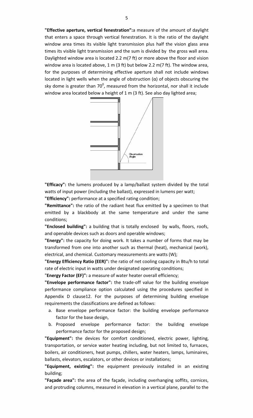
5
"Effecti e aperture, erti al fe estratio :a measure of the amount of daylight
that enters a space through vertical fenestration. It is the ratio of the daylight
window area times its visible light transmission plus half the vision glass area
times its visible light transmission and the sum is divided by the gross wall area.
Daylighted window area is located 2.2 m(7 ft) or more above the floor and vision
window area is located above, 1 m (3 ft) but below 2.2 m(7 ft). The window area,
for the purposes of determining effective aperture shall not include windows
lo ated in light ells hen the angle of o stru tion α of o je ts o s uring the sky dome is greater than 70
0, measured from the horizontal, nor shall it include
window area located below a height of 1 m (3 ft). See also day lighted area;
"Efficacy": the lumens produced by a lamp/ballast system divided by the total
watts of input power (including the ballast), expressed in lumens per watt;
"Efficiency": performance at a specified rating condition;
"Remittance": the ratio of the radiant heat flux emitted by a specimen to that
emitted by a blackbody at the same temperature and under the same
conditions;
"Enclosed building": a building that is totally enclosed by walls, floors, roofs,
and openable devices such as doors and operable windows;
"Energy": the capacity for doing work. It takes a number of forms that may be
transformed from one into another such as thermal (heat), mechanical (work),
electrical, and chemical. Customary measurements are watts (W);
"Energy Efficiency Ratio (EER)": the ratio of net cooling capacity in Btu/h to total
rate of electric input in watts under designated operating conditions;
"Energy Factor (EF)": a measure of water heater overall efficiency;
"Envelope performance factor": the trade-off value for the building envelope
performance compliance option calculated using the procedures specified in
Appendix D clause12. For the purposes of determining building envelope
requirements the classifications are defined as follows:
a. Base envelope performance factor: the building envelope performance
factor for the base design,
b. Proposed envelope performance factor: the building envelope
performance factor for the proposed design;
"Equipment": the devices for comfort conditioned, electric power, lighting,
transportation, or service water heating including, but not limited to, furnaces,
boilers, air conditioners, heat pumps, chillers, water heaters, lamps, luminaires,
ballasts, elevators, escalators, or other devices or installations;
"Equipment, existing": the equipment previously installed in an existing
building;
"Façade area": the area of the façade, including overhanging soffits, cornices,
and protruding columns, measured in elevation in a vertical plane, parallel to the
6
plane of the face of the building. Non -horizontal roof surfaces shall be included
in the calculations of vertical façade area by measuring the area in a plane
parallel to the surface;
"Fan system power": the sum of the nominal power demand (nameplate W or
HP) of motors of all fans that are required to operate at design conditions to
supply air from the heating or cooling source to the conditioned space(s) and
return it to the source of exhaust it to the outdoors;
"Fenestration": all areas (including the frames) in the building envelope that let
in light, including windows, plastic panels, clerestories, skylights, glass doors that
are more than one-half glass, and glass block walls.
a. Skylight: a fenestration surface having a slope of less than 60 degrees from
the horizontal plane. Other fenestration, even if mounted on the roof of a
building, is considered vertical fenestration.
b. Vertical fenestration: all fenestration other than skylights. Trombe wall
assemblies, where glazing is installed within 300mm (12 in) of a mass wall,
are considered walls, not fenestration;
"Fenestration area": the total area of the fenestration measured using the rough
opening and including the glazing, sash, and frame. For doors where the glazed
vision area is less than 50% of the door area, the fenestration area is the glazed
vision area. For all other doors, the fenestration area is the door area;
"Floor area gross": the sum of the floor areas of the spaces within the building
including basements, mezzanine and intermediate-floored tiers, and penthouses
with headroom height of 2.5 m (7.5 ft) or greater. It is measured from the
exterior faces of exterior walls or from the centerline of walls separating
buildings, but excluding covered walkways, open roofed-over areas, porches and
similar spaces, pipe trenches, exterior terraces or steps, chimneys, roof
overhangs, and similar features:
a. Gross building envelope floor area: the gross floor area of the building
envelope, but excluding slab-on-grade floors.
b. Gross conditioned floor area: the gross floor area of conditioned spaces.
c. Gross lighted floor area: the gross floor area of lighted spaces.
d. Gross semi-heated floor area: the gross floor area of semi-heated spaces;
"Flue damper": a device in the flue outlet or in the inlet of or upstream of the
draft control device of an individual, automatically operated, fossil fuel-fired
appliance that is designed to automatically open the flue outlet during appliance
operation and to automatically close the flue outlet when the appliance is in
standby condition;
"Fossil fuel": the fuel derived from a hydrocarbon deposit such as petroleum,
coal, or natural gas derived from living matter of a previous geologic time;
"Fuel": a material that may be used to produce heat or generate power by
combustion;
"Generally accepted engineer standard": the specification, rule, guide, or
procedure in the field of engineer or related thereto, recognized and accepted as
authoritative;
"Grade": the finished ground level adjoining a building at all exterior walls;
"Guest room": any room or rooms used or intended to be used by a guest for
sleeping purposes;
"Heat capacity": the amount of heat necessary to raise the temperature of a
given mass by 10C (1
0F). Numerically, the heatcapacity per unit area of surface
(W/m2-
0C{Btu /ft
2-0F)} is the sum of the products of the mass per unit area of
each individual material in the roof, wall, or floor surface multiplied by its
individual specific heat;
7
"Heating Seasonal Performance Factor (HSPF)": the total heating output of a
heat pump during its normal annual usage period for heating (in Btu) divided by
the total electric energy input during the same period;
"Historic": a building or space that has been specifically designed as historically
significant;
"HVAC System": the equipment, distribution systems, and terminals that
provide, either collectively or individually, the processes of heating, ventilating,
or air conditioned to a building or portion of a building;
"Infiltration": the uncontrolled inward air leakage through cracks and crevices
in any building element and around windows and doors of a building caused by
pressure differences across these elements due to factors such as wind, inside
and outside temperature differences (stack effect), and imbalance between
supply and exhaust air systems;
"Installed interior lighting power": the power in watts of all permanently
installed general, task, and furniture lighting systems and luminaires;
"Integrated part-load value (IPLV)": a single number figure of merit based on
part-load EER, COP, or kW/ton expressing part-load efficiency for air-
conditioning and heat pump equipment on the basis of weighted operation at
various load capacitates for the equipment;
"Kilovolt-ampere (kVA)": the product of the line current (amperes) times the
nominal system voltage (kilovolts) times 1.732 for three-phase currents. For
single – phase applications, kVA is the product of the line current (amperes)
times the nominal system voltage (kilovolts);
"Kilowatt (kW)": the basic unit of electric power, equal to1000W;
"Labeled": the equipment or materials to which a symbol or other identifying
mark has been attached by the manufacturer indicating compliance with
specified standard or performance in a specified manner;
"Lamp": a generic term for man-made light source often called bulb or tube;
"Lighted floor area, gross": the gross floor area of lighted spaces;
"Lighting, decorative": the lighting that is purely ornamental and installed for
aesthetic effect. Decorative lighting shall not include general lighting;
"Lighting, emergency": lighting that provides illumination only when there is a
general lighting failure;
"Lighting, general": lighting that provides a substantially uniform level of
illumination throughout an area. General lighting shall not include decorative
lighting or lighting that provides a dissimilar level of illumination to serve a
specialized application or feature within such area;
"Lighting Efficacy (LE)": the quotient of the total lumens emitted from a lamp or
lamp/ballast combination divided by the watts of input power, expressed in
lumens per watt;
"Lighting system": a group of luminaires circuited or controlled to perform a
specific function;
"Lighting power allowance":
a. Interior lighting power allowance: The maximum lighting power in watts
allowed for the interior of a building.
b. Exterior lighting power allowance: The maximum lighting power in watts
allowed for the exterior of a building;
"Lighting Power Density (LPD)": the maximum lighting power per unit of area of
a building classification of space function
"Low-rise residential": the single-family houses, multi-family structures of three
stories or fewer above grade, manufactured houses (mobile homes), and
manufactured houses (modular);
8
"Luminaries": a complete lighting unit consisting of a lamp or lamps together
with the housing designed to distribute the light, position and protect the lamps,
and connect the lamps to the power supply;
"Manual (non-automatic)": requiring personal intervention for control. Non-
automatic does not necessarily imply a manual controller, only that personal
intervention is necessary;
"Manufacturer": the company engaged in the original production and assembly
of products or equipment or a company that purchases such products and
equipment manufactured in accordance with company specifications;
"Mean temperature": one-half the sum of the minimum daily temperature and
maximum daily temperature;
"Mechanical cooling": reducing the temperature of a gas or liquid by using vapor
compression, absorption and desiccant dehumidification combined with
evaporative cooling, or another energy-driven thermodynamic cycle. Indirect or
direct evaporative cooling alone is not considered mechanical cooling;
"Metering: the instruments that measure electric voltage, current, power etc;
"Multifamily high rise": multifamily structures of four or more stories above
grade;
"Multifamily low-rise": multifamily structures of three or less stories above
grade;
"Multiplication factor (M)":indicates the relative reduction in annual solar
cooling load from overhangs and/or side fins with given projectionfactors,
relative to the respective horizontal and vertical fenestration dimensions;
No -auto ati : See Manual
"Occupant sensor": a device that detects the presence or absence of people
within an area and causes lighting, equipment, or appliances to be regulated
accordingly;
"Opaque": all areas in the building envelope, except fenestration and building
service openings such as vents and grills;
"Orientation": the direction an envelope element faces and includes the
direction of a vector perpendicular to and pointing away from the surface
outside of the element. For vertical fenestration, the twocategories are north-
oriented and all other;
"Outdoor (outside) air": air that is outside the building envelope or is taken from
the outside the building that has not been previously circulated through the
building;
"Over current": any current in excess of the rated current of the equipment of
the capacity of the conductor. It may result from overload, short circuit, or
ground fault;
"Packaged Terminal Air Conditioner (PTAC)": a factory-selected wall sleeve and
separate unencased combination of heating and cooling components,
assemblies, or sections. It may include heating capability by hot water, steam, or
electricity, and is intended for mounting through the wall to service a single
room or zone;
"Party wall": a firewall on an interior lot line used or adapted for joint service
between two buildings;
"Permanently installed": the equipment that is fixed in place and is not portable
or movable;
"Plenum": a compartment or chamber to which one or more ducts are
connected, that forms a part of the air distribution system and that is not used
for occupancy or storage. A plenum often is formed in part or in total by portions
for the building;
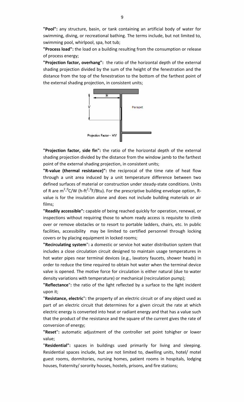
9
"Pool": any structure, basin, or tank containing an artificial body of water for
swimming, diving, or recreational bathing. The terms include, but not limited to,
swimming pool, whirlpool, spa, hot tub;
"Process load": the load on a building resulting from the consumption or release
of process energy;
"Projection factor, overhang": the ratio of the horizontal depth of the external
shading projection divided by the sum of the height of the fenestration and the
distance from the top of the fenestration to the bottom of the farthest point of
the external shading projection, in consistent units;
"Projection factor, side fin": the ratio of the horizontal depth of the external
shading projection divided by the distance from the window jamb to the farthest
point of the external shading projection, in consistent units;
"R-value (thermal resistance)": the reciprocal of the time rate of heat flow
through a unit area induced by a unit temperature difference between two
defined surfaces of material or construction under steady-state conditions. Units
of R are m2-0C/W (h-ft
2-
0F/Btu). For the prescriptive building envelope option, R-
value is for the insulation alone and does not include building materials or air
films;
"Readily accessible": capable of being reached quickly for operation, renewal, or
inspections without requiring those to whom ready access is requisite to climb
over or remove obstacles or to resort to portable ladders, chairs, etc. In public
facilities, accessibility may be limited to certified personnel through locking
covers or by placing equipment in locked rooms;
"Recirculating system": a domestic or service hot water distribution system that
includes a close circulation circuit designed to maintain usage temperatures in
hot water pipes near terminal devices (e.g., lavatory faucets, shower heads) in
order to reduce the time required to obtain hot water when the terminal device
valve is opened. The motive force for circulation is either natural (due to water
density variations with temperature) or mechanical (recirculation pump);
"Reflectance": the ratio of the light reflected by a surface to the light incident
upon it;
"Resistance, electric": the property of an electric circuit or of any object used as
part of an electric circuit that determines for a given circuit the rate at which
electric energy is converted into heat or radiant energy and that has a value such
that the product of the resistance and the square of the current gives the rate of
conversion of energy;
"Reset": automatic adjustment of the controller set point tohigher or lower
value;
"Residential": spaces in buildings used primarily for living and sleeping.
Residential spaces include, but are not limited to, dwelling units, hotel/ motel
guest rooms, dormitories, nursing homes, patient rooms in hospitals, lodging
houses, fraternity/ sorority houses, hostels, prisons, and fire stations;
10
"Roof": the upper portion of the building envelope, including opaque areas and
fenestration, that is horizontal or tilted at an angle of less than 600from
horizontal;
"Roof area, gross": the area of the roof measured from the exterior faces of
walls or from the centerline of party walls;
"Service": the equipment for delivering energy from the supply or distribution
system to the premises served;
"Service water heating": heating water for domestic or commercial purposes
other than space heating and process requirements;
"Set point": the point at which the desired temperature (0F) of the heated or
cooled space is set;
"Shading Coefficient (SC)": the ratio of solar heat gain at normal incidence
through glazing to that occurring through 3 mm (1/8 in) thick clear, double –
strength glass. Shading coefficient, as used herein, does not include interior,
exterior, or integral shading devices;
"Simulation program": a computer program that is capable of simulating the
energy performance of building systems;
"Single-zone system": HVAC system serving a single HVAC zone;
"Site -recovered energy": waste energy recovered at the building site that is
used to offset consumption of purchased fuel or electrical energy supplies;
"Skylight roof ratio (SRR)": the ratio of the total skylight area of the roof,
measured to the out side of the frame, to the gross exterior roof;
"Slab-on-grade floor": the portion of a slab floor, of the building envelope that is
in contact with ground and that is either above grade or is less than or equal to
24 in below the final elevation of the nearest exterior grade;
"Solar energy source": source of thermal, chemical, or electrical energy derived
from direction conversion of incident solar radiation at the building site;
"Solar Heat Gain Coefficient (SHGC)": the ratio of the solar heat gain entering
the space through the fenestration area to the incident solar radiation. Solar
heat gain includes directly transmitted solar heat and absorbed solar radiation,
which is then reradiated, conducted or convected into the space;
"Space": an enclosed space within a building. The classifications of spaces are as
follows for the purpose of determining building envelope requirements:
a. Conditioned space: a cooled space, heated space, or directly conditioned
space.
b. Semi- heated space: an enclosed space within a building that is heated by
a heating system whose output capacity is greater or equal to 10.7 W/m2
(3.4 Btu / h-ft2)of floor area but is not a conditioned space.
c. An enclosed space within a building that is not conditioned space or a
semi-heated space. Crawlspaces, attics, and parking garages with natural
or mechanical ventilation are not considered enclosed spaces;
"Standard Design": a computer representation of a hypothetical design based
on the actual proposed design as per appendix B. Whole Building Performance
Method.
"Storey": a portion of a building that is between one finished floor level and the
next higher finished floor level or the roof, provided, however, that a basement
or cellar shall not be considered a story;
"System": a combination of equipment and auxiliary devices (e.g., controls,
accessories, interconnecting means, and terminal elements) by which energy is
transformed so it performs a specific function such as HVAC, service water
heating, or lighting;
11
"System, existing": a system or systems previously installed in an existing
building;
"Terminal": a device by which energy from a system is finally delivered, e.g.,
registers, diffusers, lighting fixtures, faucets, etc;
"Thermal block": a collection of one or more HVAC zones grouped together for
simulation purposes. Spaces need not be contiguous to be combined within a
single thermal block;
"Thermostat": an automatic control device used to maintain temperature at a
fixed or adjustable set point;
"Tinted":(as applied to fenestration) bronze, green, or grey coloring that is
integral with the glazing material. Tinting does not include surface applied films
such as reflective coatings, applied either in the field or during the
manufacturing process;
"Transformer": a piece of electrical equipment used to convert electric power
from one voltage to another voltage;
"U-factor (Thermal Transmittance)": heat transmission in unit time through unit
area of a material or construction and the boundary air films, induced by unit
temperature difference between the environments on each side. Units of U are
W/m2-
0C (Btu/h ft
20F);
"Variable Air Volume (VAV) system": HVAC system that controls the dry bulb
temperature within a space by varying the volumetric flow of heated or cooled
supply air to the space;
"Vent damper": a device intended for installation in the venting system or an
individual, automatically operated, fossil fuel- fired appliance in the outlet or
downstream of the appliance draft control device, which is designed to
automatically open the venting system when the appliance is in operation and to
automatically close off the venting system when the appliance is in standby or
shutdown condition;
"Ventilation": the process of supplying or removing air by natural or mechanical
measures to or from any space. Such air is not required to have been
conditioned;
"Wall": the portion of the building envelope, including, opaque area and
fenestration, that is vertical or tilted at an angle of 600from horizontal or greater.
This includes above and below grade walls, between floor spandrels, peripheral
edges of floors, and foundation walls,
a. Wall, above grade: a wall that is not below grade.
b. Wall, below grade: that portion of a wall in the building envelope that is
entirely below the finish grade and in contact with the ground;
"Wall area, gross": the overall area of a wall including openings such as windows
and doors measured horizontally from outside surface to outside surface and
measured vertically from the top of the floor to the top of the roof. If roof
insulation is installed at the ceiling level rather than the roof, then the vertical
measurement is made to the top of the ceiling (Note that clause 4.3.1 does not
allow roof insulation to e located on a suspended ceiling with removable ceiling
panels). The gross wall area includes the area between the ceiling and the floor
for multi-story buildings;
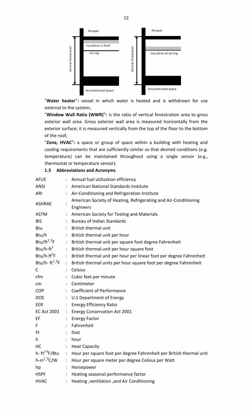
12
"Water heater": vessel in which water is heated and is withdrawn for use
external to the system;
"Window Wall Ratio (WWR)": is the ratio of vertical fenestration area to gross
exterior wall area. Gross exterior wall area is measured horizontally from the
exterior surface; it is measured vertically from the top of the floor to the bottom
of the roof;
"Zone, HVAC": a space or group of space within a building with heating and
cooling requirements that are sufficiently similar so that desired conditions (e.g.
temperature) can be maintained throughout using a single sensor (e.g.,
thermostat or temperature sensor).
1.3 Abbreviations and Acronyms
AFUE : Annual fuel utilization efficiency
ANSI : American National Standards Institute
ARI : Air-Conditioning and Refrigeration Institute
ASHRAE : American Society of Heating, Refrigerating and Air-Conditioning
Engineers
ASTM : American Society for Testing and Materials
BIS : Bureau of Indian Standards
Btu : British thermal unit
Btu/h : British thermal unit per hour
Btu/ft2-
0F : British thermal unit per square foot degree Fahrenheit
Btu/h-ft2
: British thermal unit per hour square foot
Btu/h-ft0F : British thermal unit per hour per linear foot per degree Fahrenheit
Btu/h- ft2-
0F : British thermal units per hour square foot per degree Fahrenheit
C : Celsius
cfm : Cubic feet per minute
cm : Centimeter
COP : Coefficient of Performance
DOE : U.S Department of Energy
EER : Energy Efficiency Ratio
EC Act 2001 : Energy Conservation Act 2001
EF : Energy Factor
F : Fahrenheit
Ft : foot
h : hour
HC : Heat Capacity
h- ft2 0
F/Btu : Hour per square foot per degree Fahrenheit per British thermal unit
h-m2-
0C/W : Hour per square meter per degree Celsius per Watt
hp : Horsepower
HSPF : Heating seasonal performance factor
HVAC : Heating ,ventilation ,and Air Conditioning
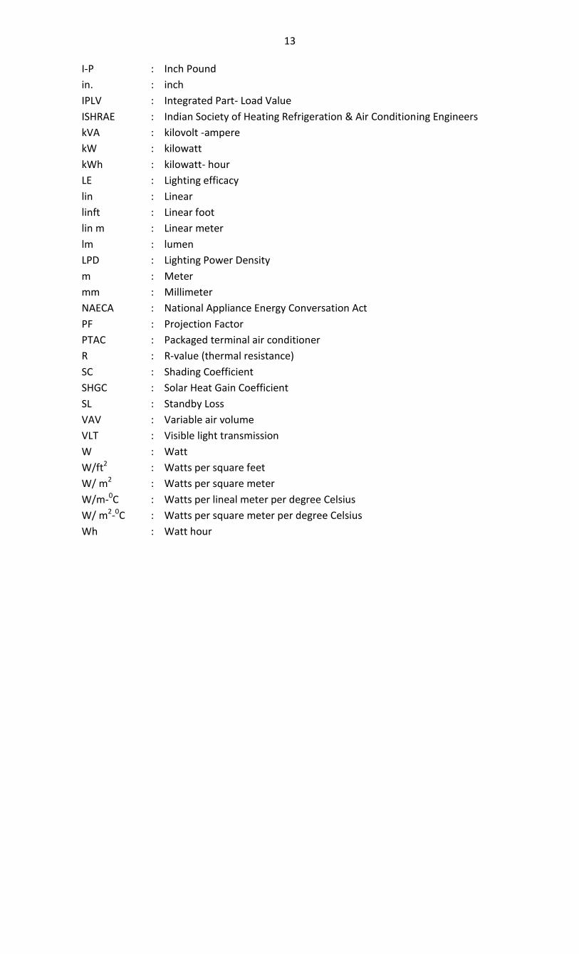
13
I-P : Inch Pound
in. : inch
IPLV : Integrated Part- Load Value
ISHRAE : Indian Society of Heating Refrigeration & Air Conditioning Engineers
kVA : kilovolt -ampere
kW : kilowatt
kWh : kilowatt- hour
LE : Lighting efficacy
lin : Linear
linft : Linear foot
lin m : Linear meter
lm : lumen
LPD : Lighting Power Density
m : Meter
mm : Millimeter
NAECA : National Appliance Energy Conversation Act
PF : Projection Factor
PTAC : Packaged terminal air conditioner
R : R-value (thermal resistance)
SC : Shading Coefficient
SHGC : Solar Heat Gain Coefficient
SL : Standby Loss
VAV : Variable air volume
VLT : Visible light transmission
W : Watt
W/ft2
: Watts per square feet
W/ m2
: Watts per square meter
W/m-0C : Watts per lineal meter per degree Celsius
W/ m2-0C : Watts per square meter per degree Celsius
Wh : Watt hour
Appendix B Whole Building Performance Method
B.1 General
B.1.1 Scope
The whole building performance method is an alternative to the prescriptive requirements contained in sec-tion 1 through section 8 of this code. It applies for all building types covered by the code.
B.1.2 Compliance
A building complies with the whole building performance method when the estimated annual energy usecost of the proposed design is less than the standard design, even though it may not comply with the spe-cific requirements of the prescriptive requirements in section 1 through section 8. The mandatory require-ments of section 1 through section 8 shall be satisfied with the whole building performance method.
B.1.3 Trade-offs Limited to Building Permit
The whole building performance method may be used for building permit applications that include lessthan the whole building; however, any design parameters that are not part of the building permit appli-cation shall be identical for both the proposed design and the standard design. Future improvements to thebuilding shall comply with both the mandatory and prescriptive requirements.
B.1.4 Documentation Requirements
Compliance shall be documented and submitted to the authority having jurisdiction. The information sub-mitted shall include the following:
(a) The annual energy use and cost for the proposed design and the standard design.
(b) A list of the energy related building features in the proposed design that is different from the stan-dard design.
(c) The input and output report (s) from the simulation program including a breakdown of energy usageby at least the following components : lights, internal equipment loads, service water heating equip-ment, space heating equipment, space cooling and heat rejection equipment, fans and other HVACequipment (such as pumps). The output reports shall also show the amount of time any loads are notmet by the HVAC system for both the proposed design and standard design.
(d) Explanation of any error messages noted in the simulation program output.
B.2 Simulation General Requirements
B.2.1 Energy Simulation Program
The simulation program shall be a computer based program for the analysis of energy consumption in build-ings and be approved by the authority having jurisdiction. The simulation program shall be as under:-
(a) Energy flows on an hourly basis for all 8,760 hours in the year;
(b) Hourly variations in occupancy, lighting power, miscellaneous equipment power, thermostat set points,and HVAC system operation, defined separately for each day of the week and holidays;
(c) Thermal mass effects;
(d) Ten or more thermal zones;
(e) Part-load and temperature dependent performance of heating and cooling equipment;
(f) Airside and water-side economizers with integrated control; and
(g) All of the standard design characteristics specified in this chapter.
40
B.2.2 Climatic Data
The simulation program shall use hourly values of climatic data, such as temperature and humidity fromrepresentative climatic data, for the city in which the proposed design is to be located. For cities or urbanregions with several climatic data entries, and for locations where weather data are not available, the de-signer shall select available weather data that best represent the climate at the construction site.
B.2.3 Compliance Calculations
The proposed design and standard design shall be calculated using the following:
(a) Same simulation program,
(b) Same weather data, and
(c) Same building operation assumptions (thermostat setpoints, schedules, internal gains, occupant loads,etc).
B.3 Calculation of Proposed Design and the Standard Design Per-formance
B.3.1 Energy Simulation model
The simulation model for calculating the proposed design and the standard design shall be developed inaccordance with the requirements in Table B.4.
B.3.2 HVAC Systems
The HVAC system type and related performance parameters for the standard design shall be determined asper table B.5 and the following rules:-
(a) Other Components: Components and parameters not listed in Table B.5 or otherwise specifically ad-dressed in this part shall be identical to those in the proposed design.(Exception to section B.3.2(a)where there are specific requirements in section 5.2.3, the component efficiency in the standard designshall be adjusted to the lowest efficiency level allowed by the requirement for that component type).
(b) All HVAC and service water heating equipment in the standard design shall be modeled at the mini-mum efficiency levels, both part load and full load, in accordance with section 5.2.3.
(c) Where efficiency ratings, such as EER and COP, include fan energy, the descriptor shall be brokendown into its components so that supply fan energy can be modeled separately.
(d) Minimum outdoor air ventilation rates shall be the same for both the standard design and the pro-posed design except when modeling demand control ventilation in proposed case
(e) The equipment capacities (i.e. system coil capacities) for the standard building design shall be basedon sizing runs for each orientation and shall be oversized by 15% for cooling and 25% for heating, i.e.,the ratio between the capacities used in the annual simulations and the capacities determined by theruns shall be 1.15 for cooling and 1.25 for heating.
(f) Unmet load hours for the proposed design shall not differ from unmet load hours for the standard de-sign by more than 50 hours. The maximum number of unmet hours shall not exceed 300 for eithercase.
B.3.3 System Fan Power
System fan electrical power for supply, return, exhaust, and relief (excluding power to fan-powered VAVboxes) shall be calculated using the following formula:
Pfan = input kW/fan motor efficiency
41
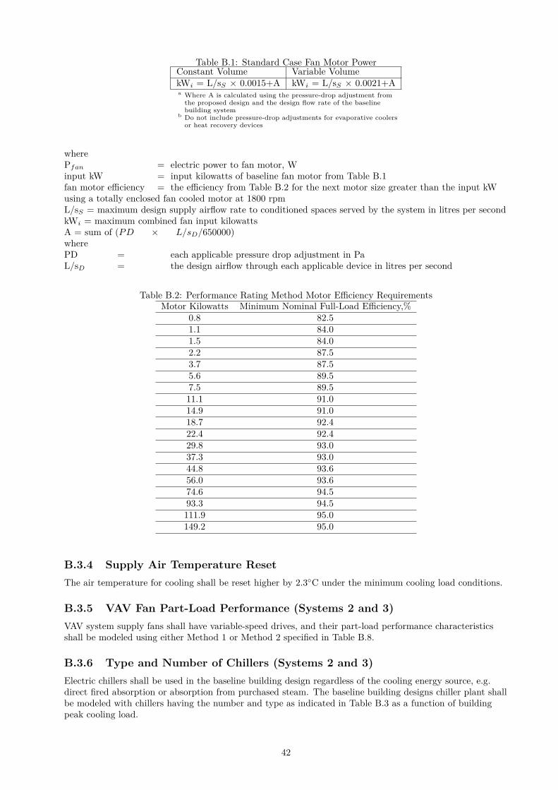
Table B.1: Standard Case Fan Motor PowerConstant Volume Variable VolumekWi = L/sS × 0.0015+A kWi = L/sS × 0.0021+Aa Where A is calculated using the pressure-drop adjustment from
the proposed design and the design flow rate of the baselinebuilding system
b Do not include pressure-drop adjustments for evaporative coolersor heat recovery devices
wherePfan = electric power to fan motor, Winput kW = input kilowatts of baseline fan motor from Table B.1fan motor efficiency = the efficiency from Table B.2 for the next motor size greater than the input kWusing a totally enclosed fan cooled motor at 1800 rpmL/sS = maximum design supply airflow rate to conditioned spaces served by the system in litres per secondkWi = maximum combined fan input kilowattsA = sum of (PD × L/sD/650000)wherePD = each applicable pressure drop adjustment in PaL/sD = the design airflow through each applicable device in litres per second
Table B.2: Performance Rating Method Motor Efficiency RequirementsMotor Kilowatts Minimum Nominal Full-Load Efficiency,%
0.8 82.51.1 84.01.5 84.02.2 87.53.7 87.55.6 89.57.5 89.511.1 91.014.9 91.018.7 92.422.4 92.429.8 93.037.3 93.044.8 93.656.0 93.674.6 94.593.3 94.5111.9 95.0149.2 95.0
B.3.4 Supply Air Temperature Reset
The air temperature for cooling shall be reset higher by 2.3◦C under the minimum cooling load conditions.
B.3.5 VAV Fan Part-Load Performance (Systems 2 and 3)
VAV system supply fans shall have variable-speed drives, and their part-load performance characteristicsshall be modeled using either Method 1 or Method 2 specified in Table B.8.
B.3.6 Type and Number of Chillers (Systems 2 and 3)
Electric chillers shall be used in the baseline building design regardless of the cooling energy source, e.g.direct fired absorption or absorption from purchased steam. The baseline building designs chiller plant shallbe modeled with chillers having the number and type as indicated in Table B.3 as a function of buildingpeak cooling load.
42
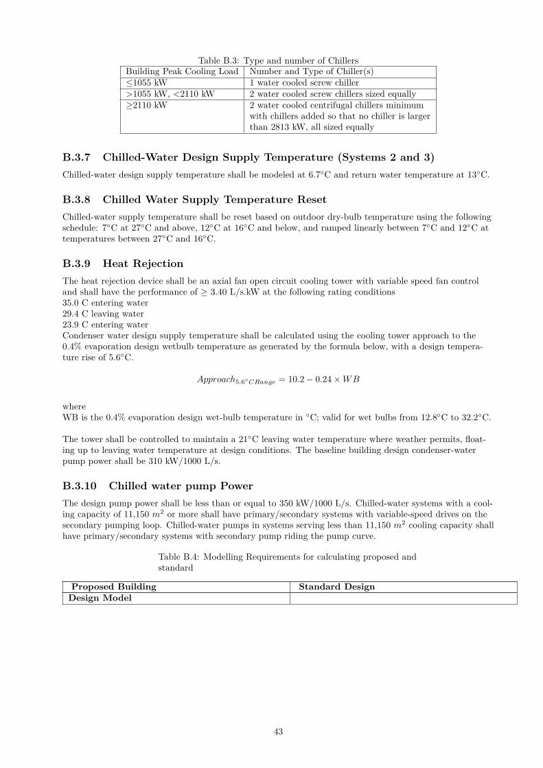
Table B.3: Type and number of ChillersBuilding Peak Cooling Load Number and Type of Chiller(s)≤1055 kW 1 water cooled screw chiller>1055 kW, <2110 kW 2 water cooled screw chillers sized equally≥2110 kW 2 water cooled centrifugal chillers minimum
with chillers added so that no chiller is largerthan 2813 kW, all sized equally
B.3.7 Chilled-Water Design Supply Temperature (Systems 2 and 3)
Chilled-water design supply temperature shall be modeled at 6.7◦C and return water temperature at 13◦C.
B.3.8 Chilled Water Supply Temperature Reset
Chilled-water supply temperature shall be reset based on outdoor dry-bulb temperature using the followingschedule: 7◦C at 27◦C and above, 12◦C at 16◦C and below, and ramped linearly between 7◦C and 12◦C attemperatures between 27◦C and 16◦C.
B.3.9 Heat Rejection
The heat rejection device shall be an axial fan open circuit cooling tower with variable speed fan controland shall have the performance of ≥ 3.40 L/s.kW at the following rating conditions35.0 C entering water29.4 C leaving water23.9 C entering waterCondenser water design supply temperature shall be calculated using the cooling tower approach to the0.4% evaporation design wetbulb temperature as generated by the formula below, with a design tempera-ture rise of 5.6◦C.
Approach5.6◦CRange = 10.2 − 0.24 × WB
whereWB is the 0.4% evaporation design wet-bulb temperature in ◦C; valid for wet bulbs from 12.8◦C to 32.2◦C.
The tower shall be controlled to maintain a 21◦C leaving water temperature where weather permits, float-ing up to leaving water temperature at design conditions. The baseline building design condenser-waterpump power shall be 310 kW/1000 L/s.
B.3.10 Chilled water pump Power
The design pump power shall be less than or equal to 350 kW/1000 L/s. Chilled-water systems with a cool-ing capacity of 11,150 m2 or more shall have primary/secondary systems with variable-speed drives on thesecondary pumping loop. Chilled-water pumps in systems serving less than 11,150 m2 cooling capacity shallhave primary/secondary systems with secondary pump riding the pump curve.
Table B.4: Modelling Requirements for calculating proposed andstandard
Proposed Building Standard DesignDesign Model
43
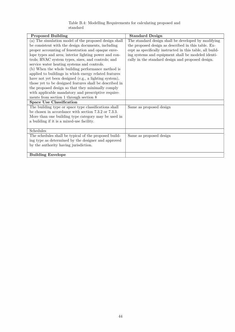
Table B.4: Modelling Requirements for calculating proposed andstandard
Proposed Building Standard Design(a) The simulation model of the proposed design shallbe consistent with the design documents, includingproper accounting of fenestration and opaque enve-lope types and area; interior lighting power and con-trols; HVAC system types, sizes, and controls; andservice water heating systems and controls.(b) When the whole building performance method isapplied to buildings in which energy related featureshave not yet been designed (e.g., a lighting system),those yet to be designed features shall be described inthe proposed design so that they minimally complywith applicable mandatory and prescriptive require-ments from section 1 through section 8
The standard design shall be developed by modifyingthe proposed design as described in this table. Ex-cept as specifically instructed in this table, all build-ing systems and equipment shall be modeled identi-cally in the standard design and proposed design.
Space Use ClassificationThe building type or space type classifications shallbe chosen in accordance with section 7.3.2 or 7.3.3.More than one building type category may be used ina building if it is a mixed-use facility.
Same as proposed design
SchedulesThe schedules shall be typical of the proposed build-ing type as determined by the designer and approvedby the authority having jurisdiction.
Same as proposed design
Building Envelope
44
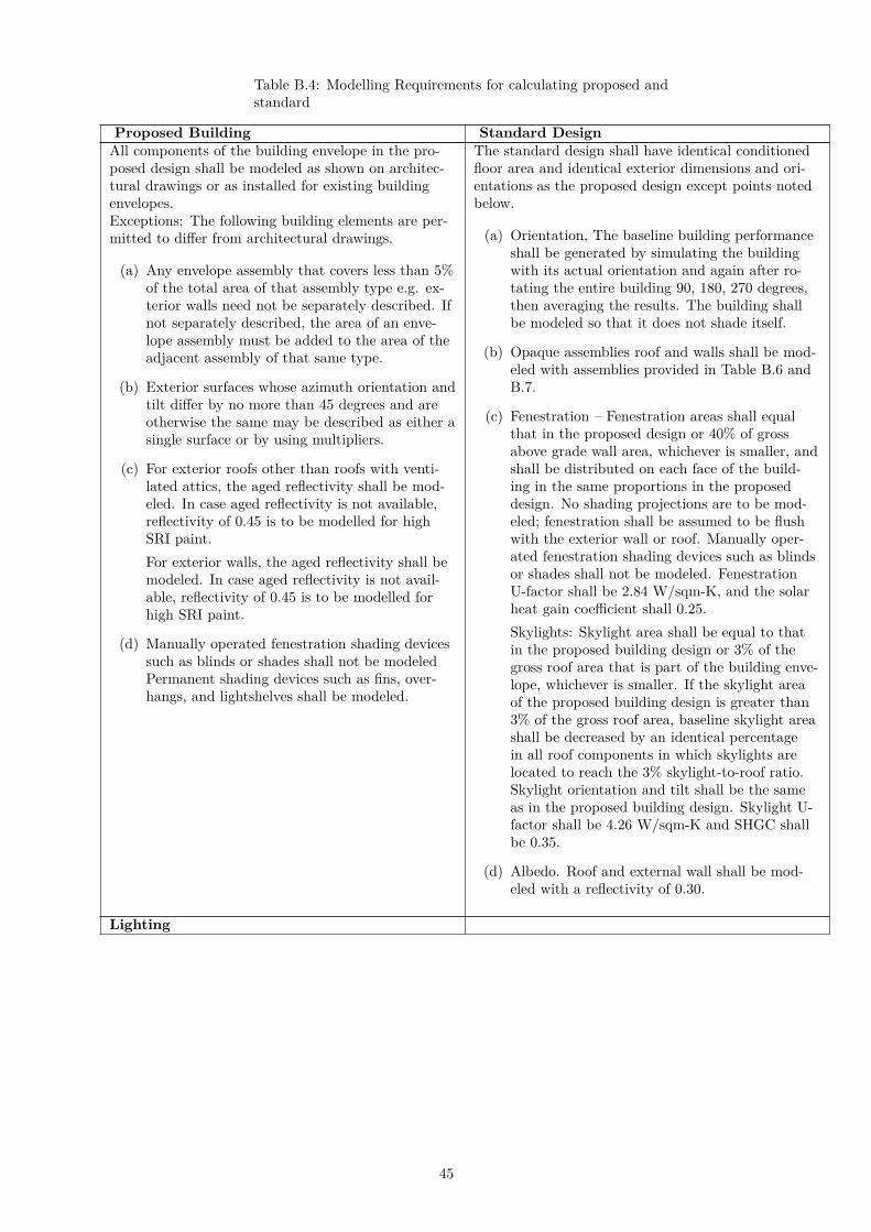
Table B.4: Modelling Requirements for calculating proposed andstandard
Proposed Building Standard DesignAll components of the building envelope in the pro-posed design shall be modeled as shown on architec-tural drawings or as installed for existing buildingenvelopes.Exceptions: The following building elements are per-mitted to differ from architectural drawings.
(a) Any envelope assembly that covers less than 5%of the total area of that assembly type e.g. ex-terior walls need not be separately described. Ifnot separately described, the area of an enve-lope assembly must be added to the area of theadjacent assembly of that same type.
(b) Exterior surfaces whose azimuth orientation andtilt differ by no more than 45 degrees and areotherwise the same may be described as either asingle surface or by using multipliers.
(c) For exterior roofs other than roofs with venti-lated attics, the aged reflectivity shall be mod-eled. In case aged reflectivity is not available,reflectivity of 0.45 is to be modelled for highSRI paint.
For exterior walls, the aged reflectivity shall bemodeled. In case aged reflectivity is not avail-able, reflectivity of 0.45 is to be modelled forhigh SRI paint.
(d) Manually operated fenestration shading devicessuch as blinds or shades shall not be modeledPermanent shading devices such as fins, over-hangs, and lightshelves shall be modeled.
The standard design shall have identical conditionedfloor area and identical exterior dimensions and ori-entations as the proposed design except points notedbelow.
(a) Orientation, The baseline building performanceshall be generated by simulating the buildingwith its actual orientation and again after ro-tating the entire building 90, 180, 270 degrees,then averaging the results. The building shallbe modeled so that it does not shade itself.
(b) Opaque assemblies roof and walls shall be mod-eled with assemblies provided in Table B.6 andB.7.
(c) Fenestration – Fenestration areas shall equalthat in the proposed design or 40% of grossabove grade wall area, whichever is smaller, andshall be distributed on each face of the build-ing in the same proportions in the proposeddesign. No shading projections are to be mod-eled; fenestration shall be assumed to be flushwith the exterior wall or roof. Manually oper-ated fenestration shading devices such as blindsor shades shall not be modeled. FenestrationU-factor shall be 2.84 W/sqm-K, and the solarheat gain coefficient shall 0.25.
Skylights: Skylight area shall be equal to thatin the proposed building design or 3% of thegross roof area that is part of the building enve-lope, whichever is smaller. If the skylight areaof the proposed building design is greater than3% of the gross roof area, baseline skylight areashall be decreased by an identical percentagein all roof components in which skylights arelocated to reach the 3% skylight-to-roof ratio.Skylight orientation and tilt shall be the sameas in the proposed building design. Skylight U-factor shall be 4.26 W/sqm-K and SHGC shallbe 0.35.
(d) Albedo. Roof and external wall shall be mod-eled with a reflectivity of 0.30.
Lighting
45
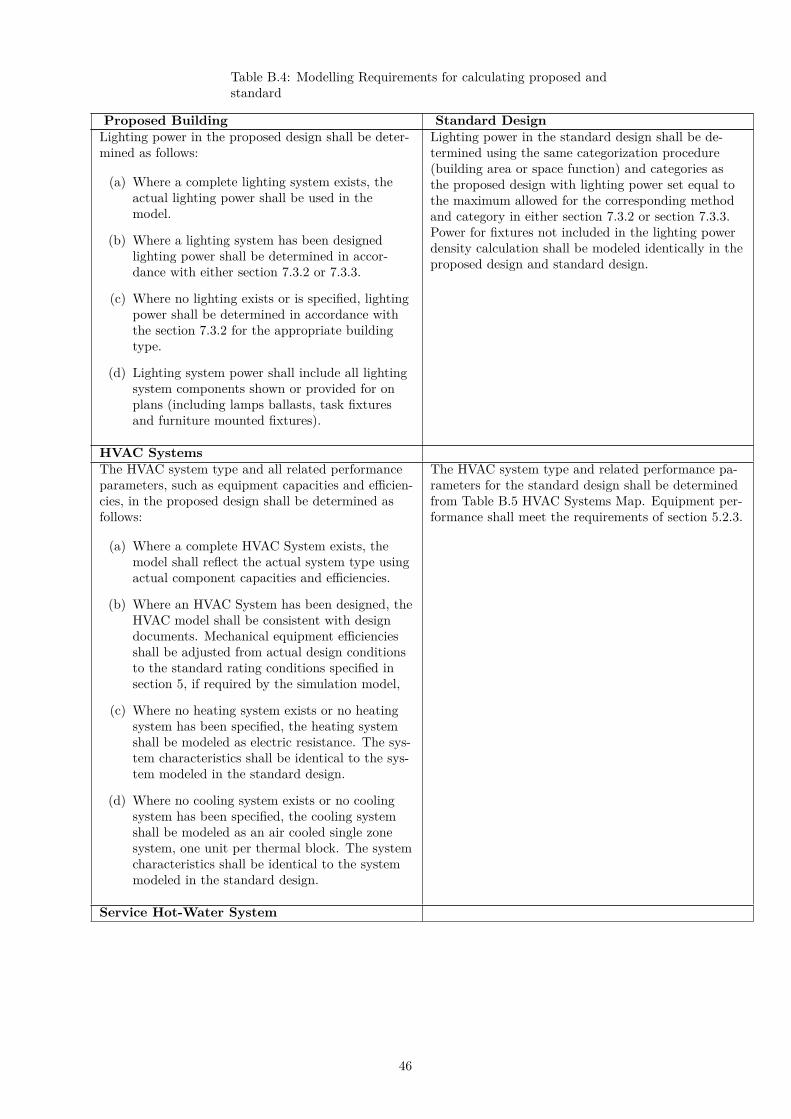
Table B.4: Modelling Requirements for calculating proposed andstandard
Proposed Building Standard DesignLighting power in the proposed design shall be deter-mined as follows:
(a) Where a complete lighting system exists, theactual lighting power shall be used in themodel.
(b) Where a lighting system has been designedlighting power shall be determined in accor-dance with either section 7.3.2 or 7.3.3.
(c) Where no lighting exists or is specified, lightingpower shall be determined in accordance withthe section 7.3.2 for the appropriate buildingtype.
(d) Lighting system power shall include all lightingsystem components shown or provided for onplans (including lamps ballasts, task fixturesand furniture mounted fixtures).
Lighting power in the standard design shall be de-termined using the same categorization procedure(building area or space function) and categories asthe proposed design with lighting power set equal tothe maximum allowed for the corresponding methodand category in either section 7.3.2 or section 7.3.3.Power for fixtures not included in the lighting powerdensity calculation shall be modeled identically in theproposed design and standard design.
HVAC SystemsThe HVAC system type and all related performanceparameters, such as equipment capacities and efficien-cies, in the proposed design shall be determined asfollows:
(a) Where a complete HVAC System exists, themodel shall reflect the actual system type usingactual component capacities and efficiencies.
(b) Where an HVAC System has been designed, theHVAC model shall be consistent with designdocuments. Mechanical equipment efficienciesshall be adjusted from actual design conditionsto the standard rating conditions specified insection 5, if required by the simulation model,
(c) Where no heating system exists or no heatingsystem has been specified, the heating systemshall be modeled as electric resistance. The sys-tem characteristics shall be identical to the sys-tem modeled in the standard design.
(d) Where no cooling system exists or no coolingsystem has been specified, the cooling systemshall be modeled as an air cooled single zonesystem, one unit per thermal block. The systemcharacteristics shall be identical to the systemmodeled in the standard design.
The HVAC system type and related performance pa-rameters for the standard design shall be determinedfrom Table B.5 HVAC Systems Map. Equipment per-formance shall meet the requirements of section 5.2.3.
Service Hot-Water System
46
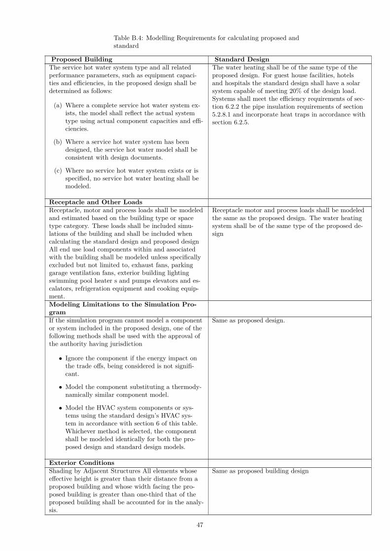
Table B.4: Modelling Requirements for calculating proposed andstandard
Proposed Building Standard DesignThe service hot water system type and all relatedperformance parameters, such as equipment capaci-ties and efficiencies, in the proposed design shall bedetermined as follows:
(a) Where a complete service hot water system ex-ists, the model shall reflect the actual systemtype using actual component capacities and effi-ciencies.
(b) Where a service hot water system has beendesigned, the service hot water model shall beconsistent with design documents.
(c) Where no service hot water system exists or isspecified, no service hot water heating shall bemodeled.
The water heating shall be of the same type of theproposed design. For guest house facilities, hotelsand hospitals the standard design shall have a solarsystem capable of meeting 20% of the design load.Systems shall meet the efficiency requirements of sec-tion 6.2.2 the pipe insulation requirements of section5.2.8.1 and incorporate heat traps in accordance withsection 6.2.5.
Receptacle and Other LoadsReceptacle, motor and process loads shall be modeledand estimated based on the building type or spacetype category. These loads shall be included simu-lations of the building and shall be included whencalculating the standard design and proposed designAll end use load components within and associatedwith the building shall be modeled unless specificallyexcluded but not limited to, exhaust fans, parkinggarage ventilation fans, exterior building lightingswimming pool heater s and pumps elevators and es-calators, refrigeration equipment and cooking equip-ment.
Receptacle motor and process loads shall be modeledthe same as the proposed design. The water heatingsystem shall be of the same type of the proposed de-sign
Modeling Limitations to the Simulation Pro-gramIf the simulation program cannot model a componentor system included in the proposed design, one of thefollowing methods shall be used with the approval ofthe authority having jurisdiction
• Ignore the component if the energy impact onthe trade offs, being considered is not signifi-cant.
• Model the component substituting a thermody-namically similar component model.
• Model the HVAC system components or sys-tems using the standard design’s HVAC sys-tem in accordance with section 6 of this table.Whichever method is selected, the componentshall be modeled identically for both the pro-posed design and standard design models.
Same as proposed design.
Exterior ConditionsShading by Adjacent Structures All elements whoseeffective height is greater than their distance from aproposed building and whose width facing the pro-posed building is greater than one-third that of theproposed building shall be accounted for in the analy-sis.
Same as proposed building design
47
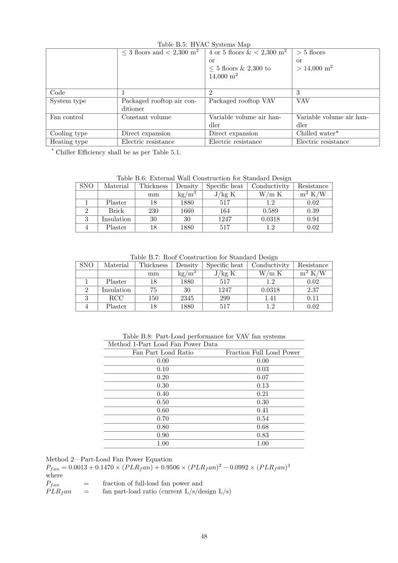
Table B.5: HVAC Systems Map≤ 3 floors and < 2,300 m2 4 or 5 floors & < 2,300 m2
or≤ 5 floors & 2,300 to14,000 m2
> 5 floorsor> 14,000 m2
Code 1 2 3System type Packaged rooftop air con-
ditionerPackaged rooftop VAV VAV
Fan control Constant volume Variable volume air han-dler
Variable volume air han-dler
Cooling type Direct expansion Direct expansion Chilled water*Heating type Electric resistance Electric resistance Electric resistance* Chiller Efficiency shall be as per Table 5.1.
Table B.6: External Wall Construction for Standard DesignSNO Material Thickness Density Specific heat Conductivity Resistance
mm kg/m3 J/kg K W/m K m2 K/W1 Plaster 18 1880 517 1.2 0.022 Brick 230 1660 164 0.589 0.393 Insulation 30 30 1247 0.0318 0.944 Plaster 18 1880 517 1.2 0.02
Table B.7: Roof Construction for Standard DesignSNO Material Thickness Density Specific heat Conductivity Resistance
mm kg/m3 J/kg K W/m K m2 K/W1 Plaster 18 1880 517 1.2 0.022 Insulation 75 30 1247 0.0318 2.373 RCC 150 2345 299 1.41 0.114 Plaster 18 1880 517 1.2 0.02
Table B.8: Part-Load performance for VAV fan systemsMethod 1-Part Load Fan Power Data
Fan Part Load Ratio Fraction Full Load Power0.00 0.000.10 0.030.20 0.070.30 0.130.40 0.210.50 0.300.60 0.410.70 0.540.80 0.680.90 0.831.00 1.00
Method 2—Part-Load Fan Power EquationPfan = 0.0013 + 0.1470 × (PLRf an) + 0.9506 × (PLRf an)2 − 0.0992 × (PLRf an)3
wherePfan = fraction of full-load fan power andPLRf an = fan part-load ratio (current L/s/design L/s)
48
Appendix C Default Values for Typical Construc-tions
C.1 Procedure for Determining Fenestration Product U-Factor andSolar Heat Gain Coefficient
U-factors and solar heat gain coefficient (SHGC) be determined for the overall fenestration product (includ-ing the sash and frame) in accordance with ISO 15099.In several cases, ISO 15099 suggests that individual national standards will need to be more specific and inother cases the ISO document gives users the choice of two options. This part clarifies these specific issuesas they are to be implemented for this code:
1. clause 4.1 of ISO 15099: For calculating the overall U- factor , ISO 15099 offers a choice betweenthe linear thermal transmittance (4.1.2) and the area weighted method ( 4.1.3). The area weightedmethod (4.1.3) shall be used.
2. clause 4.2.2 of ISO 15099: Frame and divider SHGC’s shall be calculated in accordance with clause4.2.2.
3. clause 6.4 of ISO 15099 refers the issue of material properties to national standards. Material conduc-tivities and emissivities shall be determined in accordance with Indian standards.
4. clause 7 of ISO 15099 on shading systems is currently excluded.
5. clause 8.2 of ISO 15099 addresses environmental conditions. The following are defined for India:For U factor calculations:
Tin = 24◦C
Tout = 32◦C
V = 3.35m/s
T/m, out = Tout
T/m, in = Tin
Is = 0W/m2
For SHGC calculations:Tin = 24◦C
Tout = 32◦C
V = 2.75m/s
T/m, out = Tout
T/m, in = Tin
Is = 783W/m2
6. clause 8.3 of ISO 15099 addresses convective film coefficients on the interior and exterior of the Win-dow product in clause 8.3.1 of ISO 15099, simulations shall use the heat transfer coefficient based onthe center of glass temperature and the entire window height ; this film coefficient shall be used on allindoor surfaces„ including frame sections. In clause 8.3.2 of ISO 15099, the formula from this sectionshall be applied to all outdoor exposed surfaces.
7. clause 8.4.2 of ISO 15099 presents two possible approaches for in corporating the impacts of self-viewingsurfaces on interior radiative heat transfer calculations. Products shall use the method in clause 8.4.2.1of ISO 15099 (Two–Dimensional Element to Element View Factor Based Radiation Heat Transfer Cal-culation). The alternate approach in clause 8.4.3 of ISO 15099 shall not be used.
49
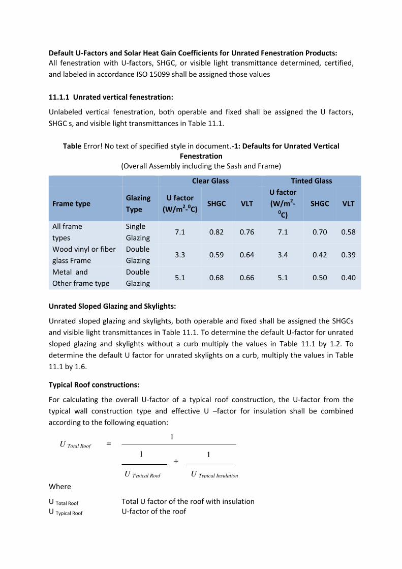
Default U-Factors and Solar Heat Gain Coefficients for Unrated Fenestration Products:
All fenestration with U-factors, SHGC, or visible light transmittance determined, certified,
and labeled in accordance ISO 15099 shall be assigned those values
11.1.1 Unrated vertical fenestration:
Unlabeled vertical fenestration, both operable and fixed shall be assigned the U factors,
SHGC s, and visible light transmittances in Table 11.1.
Table Error! No text of specified style in document.-1: Defaults for Unrated Vertical
Fenestration
(Overall Assembly including the Sash and Frame)
Clear Glass Tinted Glass
Frame type Glazing
Type
U factor
(W/m2-
0C)
SHGC VLT
U factor
(W/m2-
0C)
SHGC VLT
All frame
types
Single
Glazing 7.1 0.82 0.76 7.1 0.70 0.58
Wood vinyl or fiber
glass Frame
Double
Glazing 3.3 0.59 0.64 3.4 0.42 0.39
Metal and
Other frame type
Double
Glazing 5.1 0.68 0.66 5.1 0.50 0.40
Unrated Sloped Glazing and Skylights:
Unrated sloped glazing and skylights, both operable and fixed shall be assigned the SHGCs
and visible light transmittances in Table 11.1. To determine the default U-factor for unrated
sloped glazing and skylights without a curb multiply the values in Table 11.1 by 1.2. To
determine the default U factor for unrated skylights on a curb, multiply the values in Table
11.1 by 1.6.
Typical Roof constructions:
For calculating the overall U-factor of a typical roof construction, the U-factor from the
typical wall construction type and effective U –factor for insulation shall be combined
according to the following equation:
Where
U Total Roof Total U factor of the roof with insulation
U Typical Roof U-factor of the roof
U Total Roof = 1
1 1 +
U Typical Roof U Typical Insulation
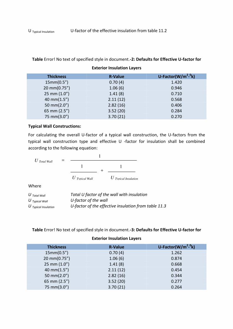
U Typical Insulation U-factor of the effective insulation from table 11.2
Table Error! No text of specified style in document.-2: Defaults for Effective U-factor for
Exterior Insulation Layers
Thickness R-Value U-Factor(W/m2-0k)
. ” 0.70 (4) 1.420
. ” 1.06 (6) 0.946
. ” 1.41 (8) 0.710
. ” 2.11 (12) 0.568
50 . ” 2.82 (16) 0.406
. ” 3.52 (20) 0.284
. ” 3.70 (21) 0.270
Typical Wall Constructions:
For calculating the overall U-factor of a typical wall construction, the U-factors from the
typical wall construction type and effective U -factor for insulation shall be combined
according to the following equation:
Where
U Total Wall Total U factor of the wall with insulation
U Typical Wall U-factor of the wall
U Typical Insulation U-factor of the effective insulation from table 11.3
Table Error! No text of specified style in document.-3: Defaults for Effective U-factor for
Exterior Insulation Layers
Thickness R-Value U-Factor(W/m2-0k)
. ” 0.70 (4) 1.262
. ” 1.06 (6) 0.874
. ” 1.41 (8) 0.668
. ” 2.11 (12) 0.454
. ” 2.82 (16) 0.344
. ” 3.52 (20) 0.277
. ” 3.70 (21) 0.264
U Total Wall = 1
1 1 +
U Typical Wall U Typical Insulation
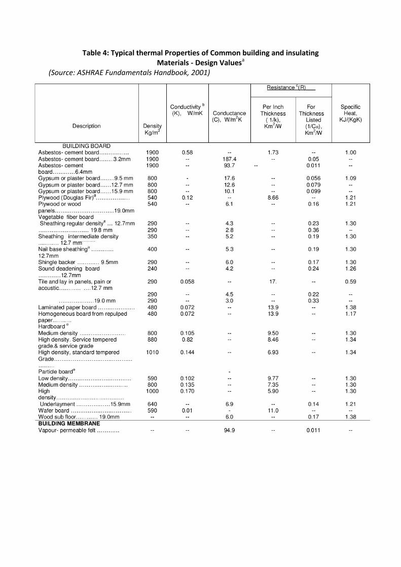
Table 4: Typical thermal Properties of Common building and insulating
Materials - Design Valuesa
(Source: ASHRAE Fundamentals Handbook, 2001)
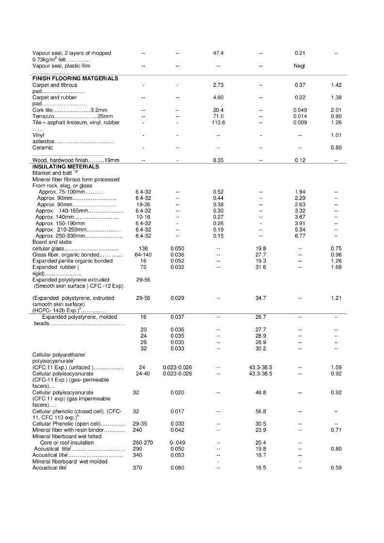
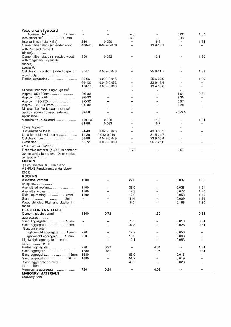
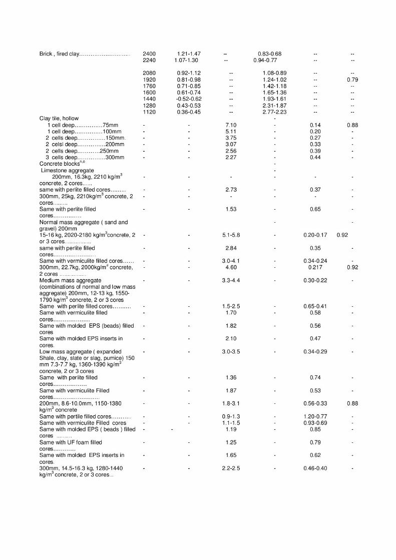
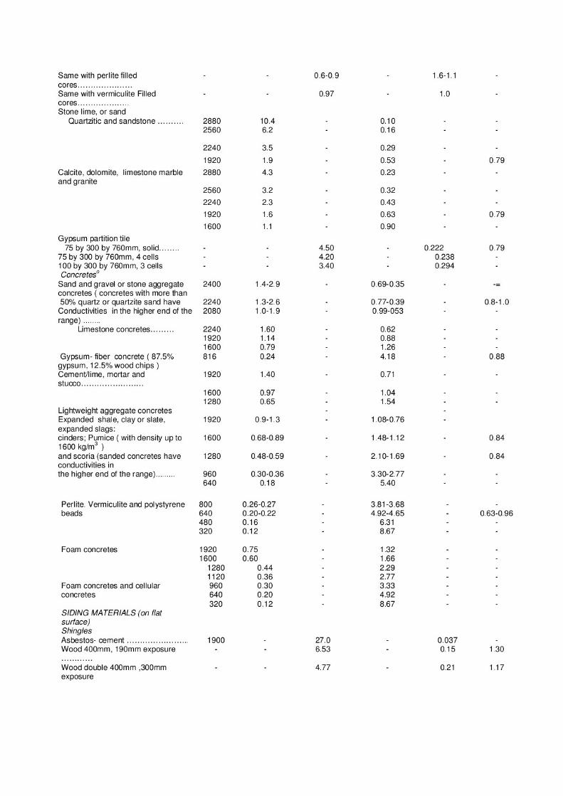
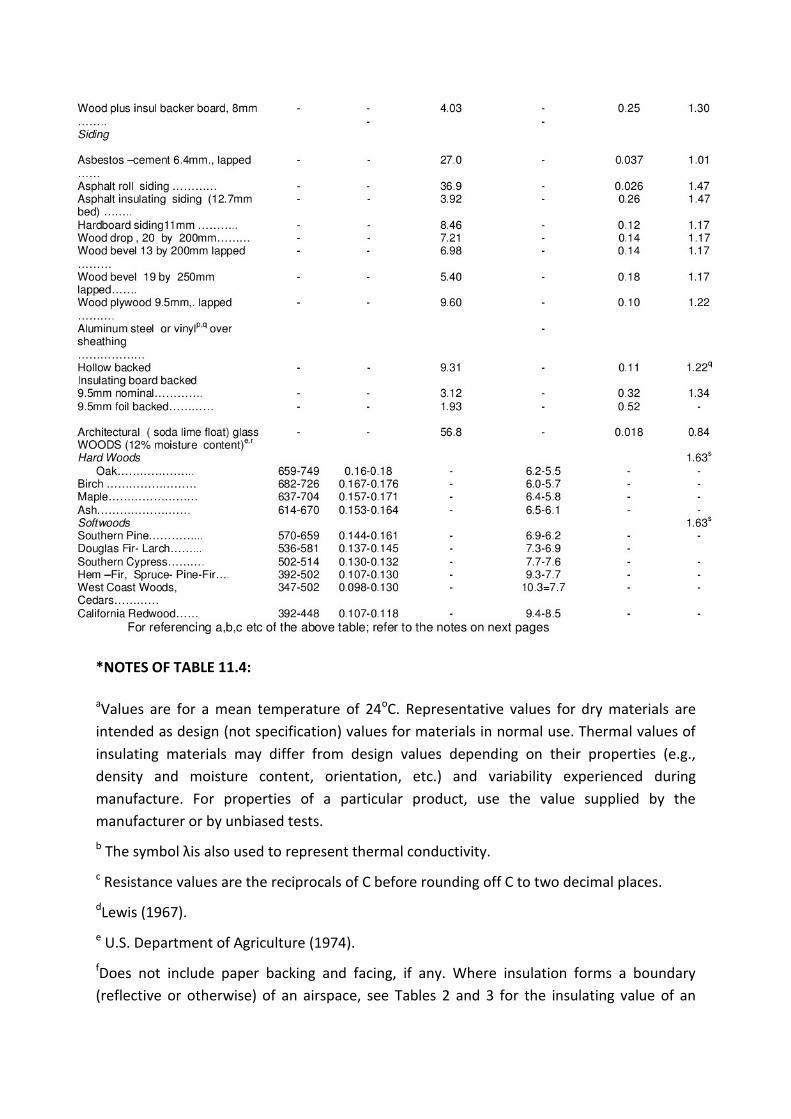
*NOTES OF TABLE 11.4:
aValues are for a mean temperature of 24
oC. Representative values for dry materials are
intended as design (not specification) values for materials in normal use. Thermal values of
insulating materials may differ from design values depending on their properties (e.g.,
density and moisture content, orientation, etc.) and variability experienced during
manufacture. For properties of a particular product, use the value supplied by the
manufacturer or by unbiased tests.
b The sy ol λis also used to represe t ther al o du tivity.
c Resistance values are the reciprocals of C before rounding off C to two decimal places.
dLewis (1967).
e U.S. Department of Agriculture (1974).
fDoes not include paper backing and facing, if any. Where insulation forms a boundary
(reflective or otherwise) of an airspace, see Tables 2 and 3 for the insulating value of an
airspace with the appropriate effective emittance and temperature conditions of the space.
Conductivity varies with fiber diameter. (See Chapter 23, Factors Affecting Thermal
Performance). Batt, blanket, and loose-fill mineralfiber insulations are manufactured to
achieve specified R-values, the most common of which are listed in the table. Due to
differences in manufacturing processes and materials, the product thicknesses, densities,
and thermal conductivities vary over considerable ranges for a specified R-value.
hThis material is relatively new and data are based on limited testing.
iFor additional information, see Society of PlasticsEngineers (SPI) Bulletin U108. Values are
for aged, unfaced board stock. For change in conductivity with age of expanded
polyurethane/ polyisocyanurate, see Chapter 23, Factors AffectingThermal Performance.
j Values are for aged products with gas-impermeable facers on the two major surfaces. An
aluminium foil facer of 25 µm thickness or greater is generally considered impermeable to
gases. For change in conductivity with age of expanded polyisocyanurate, see Chapter 23,
Factors Affecting Thermal Performance, and SPI Bulletin U108.
kCellular phenolic insulation may no longer be manufactured. The thermal conductivity and
resistance values do not represent aged insulation,which may have a higher thermal
conductivity and lower thermal resistance. lInsulating values of acoustical tile vary,
depending on density of the board and on type, size, and depth of perforations.
m Cavity is framed with 20mm wood furring strips. Caution should be used in applying this
value for other framing materials. The reported value wasderived from tests and applies to
the reflective path only. The effect of studs or furring strips must be included in determining
the overall performance of the wall.
nValues for fully grouted block may be approximated using values for concrete with a similar
unit density.
oValues for concrete block and concrete are at moisture contents representative of normal
use.
pValues for metal or vinyl siding applied over flat surfaces vary widely, depending on
amount of ventilation of airspace beneath the siding; whether air space is reflective or non
reflective; and on thickness, type, and application of insulating backing-board used. Values
are averages for use as design guides, and were obtained from several guarded hot box
tests (ASTM C 236) or calibrated hot box (ASTM C 976) on hollow-backed types and types
made using backing of wood fiber, foamed plastic, and glass fiber. Departures of +50% or
more from these values may occur.
q Vinyl specific heat= 1.0 kJ/(kg.K)
rSee Adams (1971), MacLean (1941), and Wilkes (1979). The conductivity values listed are
for heat transfer across the grain. The thermal conductivity of wood varies linearly with the
density, and the density ranges listed are those normally found for the wood species given.
If the density of the wood species is not known, use the mean conductivity value. For
extrapolation to other moisture contents, the following empirical equation developed by
Wilkes (1979) may be used:
Where p is density of the moist wood in kg/m3, and M is the moisture content in percent.
sFrom Wilkes (1979), an empirical equation for the specific heat of moist wood at 24
oC is as
follows:
Where Dcp accounts for the heat of absorption and is denoted by DCp = M(0.008037 - 1.325
x 10-4
M)
Where M is the moisture content in percent by mass.
Assuming parallel heat flow only, the calculated resistance is higher than that calculated on
the assumption of isothermal planes. The actual resistance generally is some value between
the two calculated values. In the absence of test values, examination of the construction
usually reveals whether a value closer to the higher or lower calculated R-value should be
used. Generally, if the construction contains a layer in which lateral conduction is high
compared with transmittance through the construction, the calculation with isothermal
planes should be used.
If the construction has no layer of high lateral conductance, the parallel heat flow
calculation should be used. Hot box tests of insulated and uninsulatedmasonry walls
constructed withblock of conventional configuration show that thermal resistances
calculated using the isothermal planes heat flow method agree well with measured values
(Van Greem 1985, Valore 1980, Shu et al. 1979). Neglecting horizontal motor joints in
conventional block can result in thermal transmittance values up to 16% lower than actual,
depending on the density and thermal properties of the masonry, and 1 to 6% lower,
depending on the core insulationmaterial (Van Greem 1985, McIntyre 1984). For aerated
concrete block walls, other solid masonry, and multicore block walls with full mortar joints,
neglecting mortar joints can cause errors in R-values up to 40% (Valore 1988). Horizontal
motor joints usually found in concrete block wall construction are neglected in Example 2.
Constructions Containing Metal
Curtain and metal stud-wall constructions often include metallic and other thermal bridges,
which can significantly reduce the thermal resistance. However, the capacity of the adjacent
facing materials to transmit heat transversely to the metal is limited, and some contact
resistance between all materials in contact limits the reduction. Contact resistances in
building structures are only 0.01 to 0.1 K.m2/W-too small to be of concern in many cases.
However, the contact resistances of steel framing members may be important. Also, in
many cases (as illustrated in Example 3), the area of metal in contact with the facing greatly
exceeds the thickness of the metal, which mitigates the contact resistance effects.
Thermal characteristics for panels of sandwich construction can be computed by combining
the thermal resistances of the various layers. R-valuesfor the assembled sections should be
determined on a representative sample by using a hot box method. If the sample is a wall
section with air cavities on both sides of fibrous insulation, the sample must be of
representative height since convective airflow can contribute significantly to heat flow
through the test section. Computer modeling can also be useful, but all heat transfer
mechanisms must be considered. In Example 3, the metal member is only 0.5 mm thick, but
it is in contact with adjacent facings over a 32mm-wide area. The steel member is 90 mm
deep, hasa thermal resistance of approximately 0.0019 K.m2/W, and is virtually isothermal.
The calculation Involves careful selection of the appropriate thickness for the steel member.
If the member is assumed to be 0.5 mm thick, the fact that the flange transmits heat to the
adjacent facing is ignored, and the heat flow through the steel is underestimated. If the
member is assumed to be 32 mm thick, the heat flow through the steel is overestimated. In
Example 3, the steel member behaves in much the same way as a rectangular member 32
mm thick and 90 mm deep.
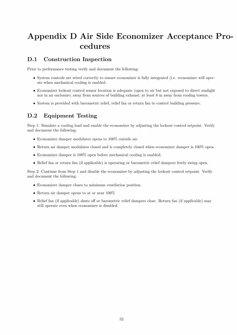
Appendix D Air Side Economizer Acceptance Pro-
cedures
D.1 Construction Inspection
Prior to performance testing verify and document the following:
• System controls are wired correctly to ensure economizer is fully integrated (i.e. economizer will oper-ate when mechanical cooling is enabled.
• Economizer lockout control sensor location is adequate (open to air but not exposed to direct sunlightnor in an enclosure; away from sources of building exhaust; at least 8 m away from cooling towers.
• System is provided with barometric relief, relief fan or return fan to control building pressure.
D.2 Equipment Testing
Step 1: Simulate a cooling load and enable the economizer by adjusting the lockout control setpoint. Verifyand document the following:
• Economizer damper modulates opens to 100% outside air.
• Return air damper modulates closed and is completely closed when economizer damper is 100% open.
• Economizer damper is 100% open before mechanical cooling is enabled.
• Relief fan or return fan (if applicable) is operating or barometric relief dampers freely swing open.
Step 2: Continue from Step 1 and disable the economizer by adjusting the lockout control setpoint. Verifyand document the following:
• Economizer damper closes to minimum ventilation position.
• Return air damper opens to at or near 100%
• Relief fan (if applicable) shuts off or barometric relief dampers close. Return fan (if applicable) maystill operate even when economizer is disabled.
52
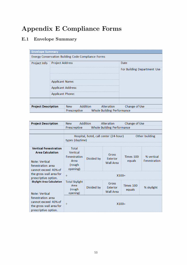
Appendix E Compliance Forms
E.1 Envelope Summary
53
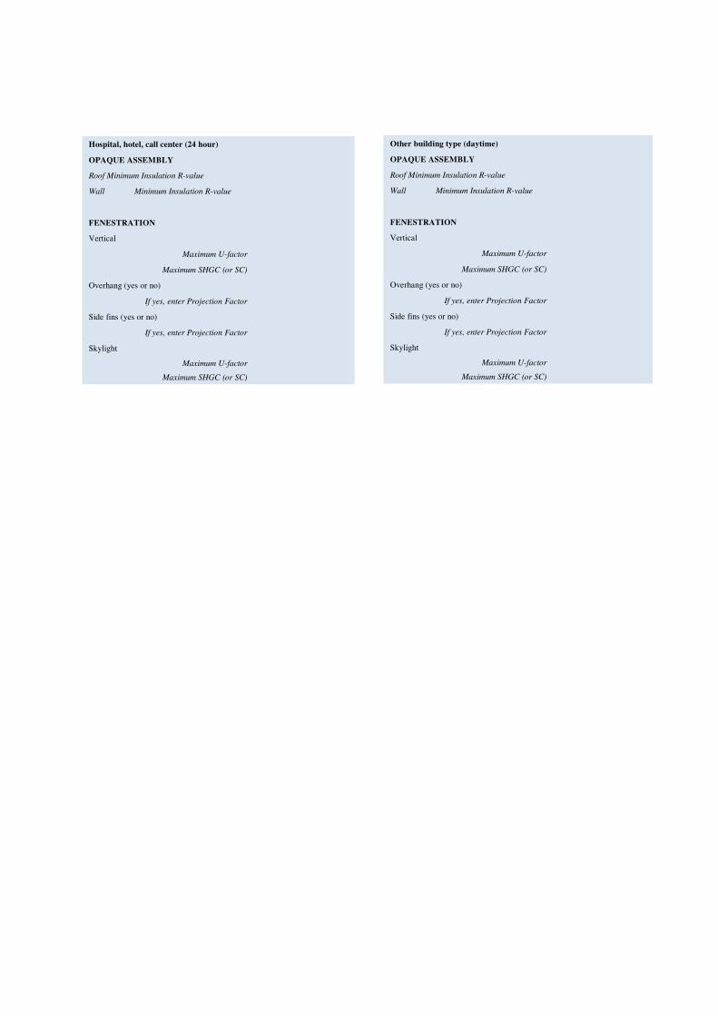
Hospital, hotel, call center (24 hour)
OPAQUE ASSEMBLY
Roof Minimum Insulation R-value
Wall Minimum Insulation R-value
FENESTRATION
Vertical
Maximum U-factor
Maximum SHGC (or SC)
Overhang (yes or no)
If yes, enter Projection Factor
Side fins (yes or no)
If yes, enter Projection Factor
Skylight
Maximum U-factor
Maximum SHGC (or SC)
Other building type (daytime)
OPAQUE ASSEMBLY
Roof Minimum Insulation R-value
Wall Minimum Insulation R-value
FENESTRATION
Vertical
Maximum U-factor
Maximum SHGC (or SC)
Overhang (yes or no)
If yes, enter Projection Factor
Side fins (yes or no)
If yes, enter Projection Factor
Skylight
Maximum U-factor
Maximum SHGC (or SC)
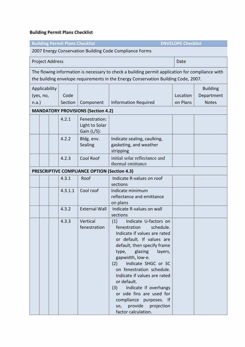
Building Permit Plans Checklist
Building Permit Plans Checklist ENVELOPE Checklist
2007 Energy Conservation Building Code Compliance Forms
Project Address Date
The flowing information is necessary to check a building permit application for compliance with
the building envelope requirements in the Energy Conservation Building Code, 2007.
Applicability
(yes, no,
n.a.)
Code
Section Component Information Required
Location
on Plans
Building
Department
Notes
MANDATORY PROVISIONS (Section 4.2)
4.2.1 Fenestration:
Light to Solar
Gain (L/S):
4.2.2 Bldg. env.
Sealing
Indicate sealing, caulking,
gasketing, and weather
stripping
4.2.3 Cool Roof initial solar reflectance and
thermal emittance
PRESCRIPTIVE COMPLIANCE OPTION (Section 4.3)
4.3.1 Roof Indicate R-values on roof
sections
4.3.1.1 Cool roof Indicate minimum
reflectance and emittance
on plans
4.3.2 External Wall Indicate R-values on wall
sections
4.3.3 Vertical
fenestration
(1) Indicate U-factors on
fenestration schedule.
Indicate if values are rated
or default. If values are
default, then specify frame
type, glazing layers,
gapwidth, low-e.
(2) Indicate SHGC or SC
on fenestration schedule.
Indicate if values are rated
or default.
(3) Indicate if overhangs
or side fins are used for
compliance purposes. If
so, provide projection
factor calculation.
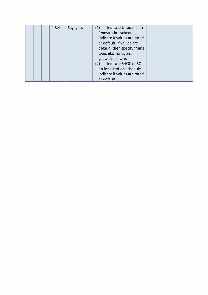
4.3.4 Skylights (1) Indicate U-factors on
fenestration schedule.
Indicate if values are rated
or default. If values are
default, then specify frame
type, glazing layers,
gapwidth, low-e.
(2) Indicate SHGC or SC
on fenestration schedule.
Indicate if values are rated
or default
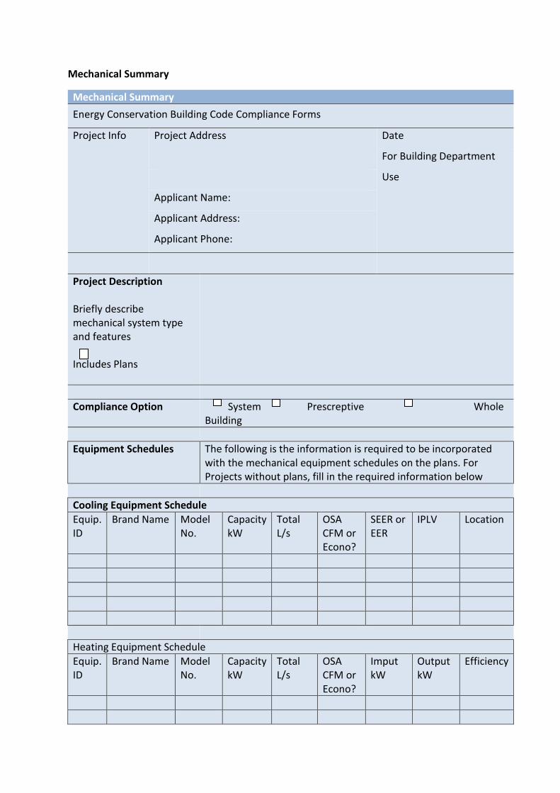
Mechanical Summary
Mechanical Summary
Energy Conservation Building Code Compliance Forms
Project Info Project Address Date
For Building Department
Use
Applicant Name:
Applicant Address:
Applicant Phone:
Project Description
Briefly describe
mechanical system type
and features
Includes Plans
Compliance Option System Prescreptive Whole
Building
Equipment Schedules The following is the information is required to be incorporated
with the mechanical equipment schedules on the plans. For
Projects without plans, fill in the required information below
Cooling Equipment Schedule
Equip.
ID
Brand Name Model
No.
Capacity
kW
Total
L/s
OSA
CFM or
Econo?
SEER or
EER
IPLV Location
Heating Equipment Schedule
Equip.
ID
Brand Name Model
No.
Capacity
kW
Total
L/s
OSA
CFM or
Econo?
Imput
kW
Output
kW
Efficiency
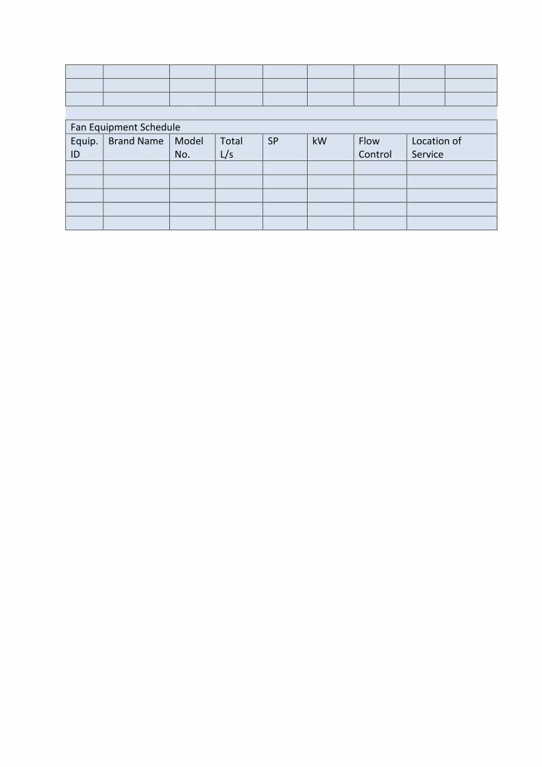
Fan Equipment Schedule
Equip.
ID
Brand Name Model
No.
Total
L/s
SP kW Flow
Control
Location of
Service
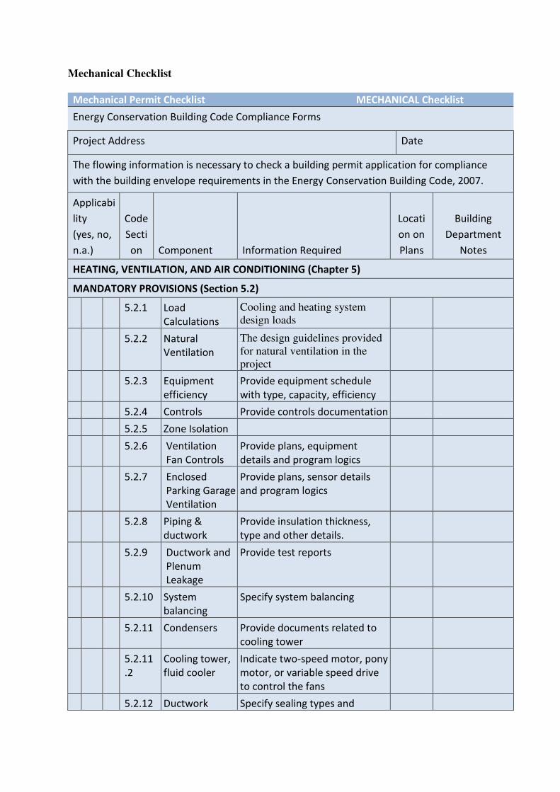
Mechanical Checklist
Mechanical Permit Checklist MECHANICAL Checklist
Energy Conservation Building Code Compliance Forms
Project Address Date
The flowing information is necessary to check a building permit application for compliance
with the building envelope requirements in the Energy Conservation Building Code, 2007.
Applicabi
lity
(yes, no,
n.a.)
Code
Secti
on Component Information Required
Locati
on on
Plans
Building
Department
Notes
HEATING, VENTILATION, AND AIR CONDITIONING (Chapter 5)
MANDATORY PROVISIONS (Section 5.2)
5.2.1 Load
Calculations
Cooling and heating system
design loads
5.2.2 Natural
Ventilation
The design guidelines provided
for natural ventilation in the
project
5.2.3 Equipment
efficiency
Provide equipment schedule
with type, capacity, efficiency
5.2.4 Controls Provide controls documentation
5.2.5 Zone Isolation
5.2.6 Ventilation
Fan Controls
Provide plans, equipment
details and program logics
5.2.7 Enclosed
Parking Garage
Ventilation
Provide plans, sensor details
and program logics
5.2.8 Piping &
ductwork
Provide insulation thickness,
type and other details.
5.2.9 Ductwork and
Plenum
Leakage
Provide test reports
5.2.10 System
balancing
Specify system balancing
5.2.11 Condensers Provide documents related to
cooling tower
5.2.11
.2
Cooling tower,
fluid cooler
Indicate two-speed motor, pony
motor, or variable speed drive
to control the fans
5.2.12 Ductwork Specify sealing types and
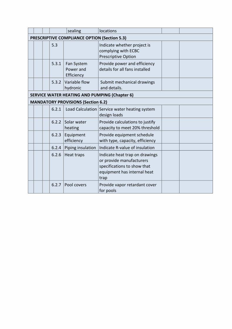
sealing locations
PRESCRIPTIVE COMPLIANCE OPTION (Section 5.3)
5.3 Indicate whether project is
complying with ECBC
Prescriptive Option
5.3.1 Fan System
Power and
Efficiency
Provide power and efficiency
details for all fans installed
5.3.2 Variable flow
hydronic
Submit mechanical drawings
and details.
SERVICE WATER HEATING AND PUMPING (Chapter 6)
MANDATORY PROVISIONS (Section 6.2)
6.2.1 Load Calculation Service water heating system
design loads
6.2.2 Solar water
heating
Provide calculations to justify
capacity to meet 20% threshold
6.2.3 Equipment
efficiency
Provide equipment schedule
with type, capacity, efficiency
6.2.4 Piping insulation Indicate R-value of insulation
6.2.6 Heat traps Indicate heat trap on drawings
or provide manufacturers
specifications to show that
equipment has internal heat
trap
6.2.7 Pool covers Provide vapor retardant cover
for pools
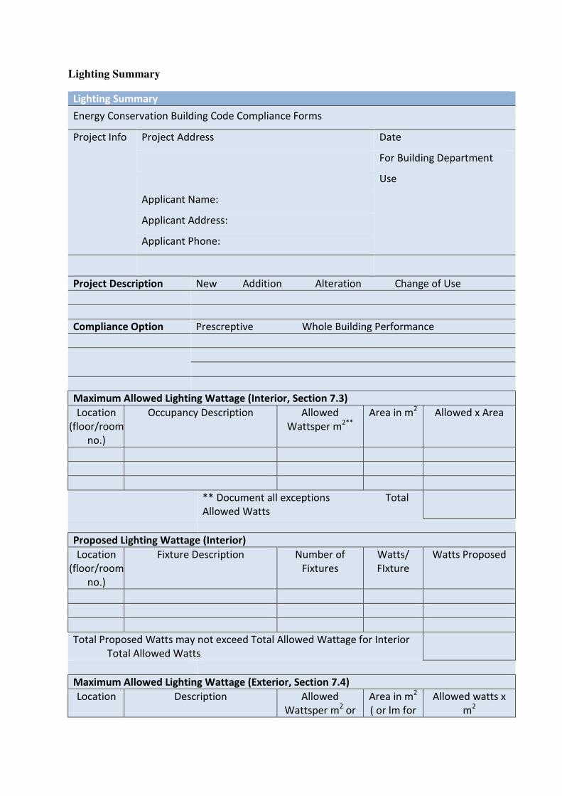
Lighting Summary
Lighting Summary
Energy Conservation Building Code Compliance Forms
Project Info Project Address Date
For Building Department
Use
Applicant Name:
Applicant Address:
Applicant Phone:
Project Description New Addition Alteration Change of Use
Compliance Option Prescreptive Whole Building Performance
Maximum Allowed Lighting Wattage (Interior, Section 7.3)
Location
(floor/room
no.)
Occupancy Description Allowed
Wattsper m2**
Area in m2 Allowed x Area
** Document all exceptions Total
Allowed Watts
Proposed Lighting Wattage (Interior)
Location
(floor/room
no.)
Fixture Description Number of
Fixtures
Watts/
FIxture
Watts Proposed
Total Proposed Watts may not exceed Total Allowed Wattage for Interior
Total Allowed Watts
Maximum Allowed Lighting Wattage (Exterior, Section 7.4)
Location Description Allowed
Wattsper m2 or
Area in m2
( or lm for
Allowed watts x
m2
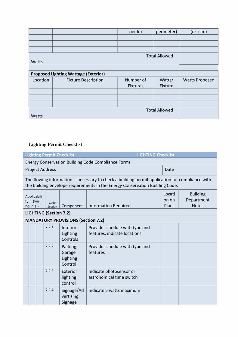
per lm perimeter) (or x lm)
Total Allowed
Watts
Proposed Lighting Wattage (Exterior)
Location Fixture Description Number of
Fixtures
Watts/
FIxture
Watts Proposed
Total Allowed
Watts
Lighting Permit Checklist
Lighting Permit Checklist LIGHTING Checklist
Energy Conservation Building Code Compliance Forms
Project Address Date
The flowing information is necessary to check a building permit application for compliance with
the building envelope requirements in the Energy Conservation Building Code.
Applicabili
ty (yes,
no, n.a.) Code
Section Component Information Required
Locati
on on
Plans
Building
Department
Notes
LIGHTING (Section 7.2)
MANDATORY PROVISIONS (Section 7.2)
7.2.1 Interior
Lighting
Controls
Provide schedule with type and
features, indicate locations
7.2.2 Parking
Garage
Lighting
Control
Provide schedule with type and
features
7.2.3 Exterior
lighting
control
Indicate photosensor or
astronomical time switch
7.2.4 Signage/Ad
vertising
Signage
Indicate 5 watts maximum
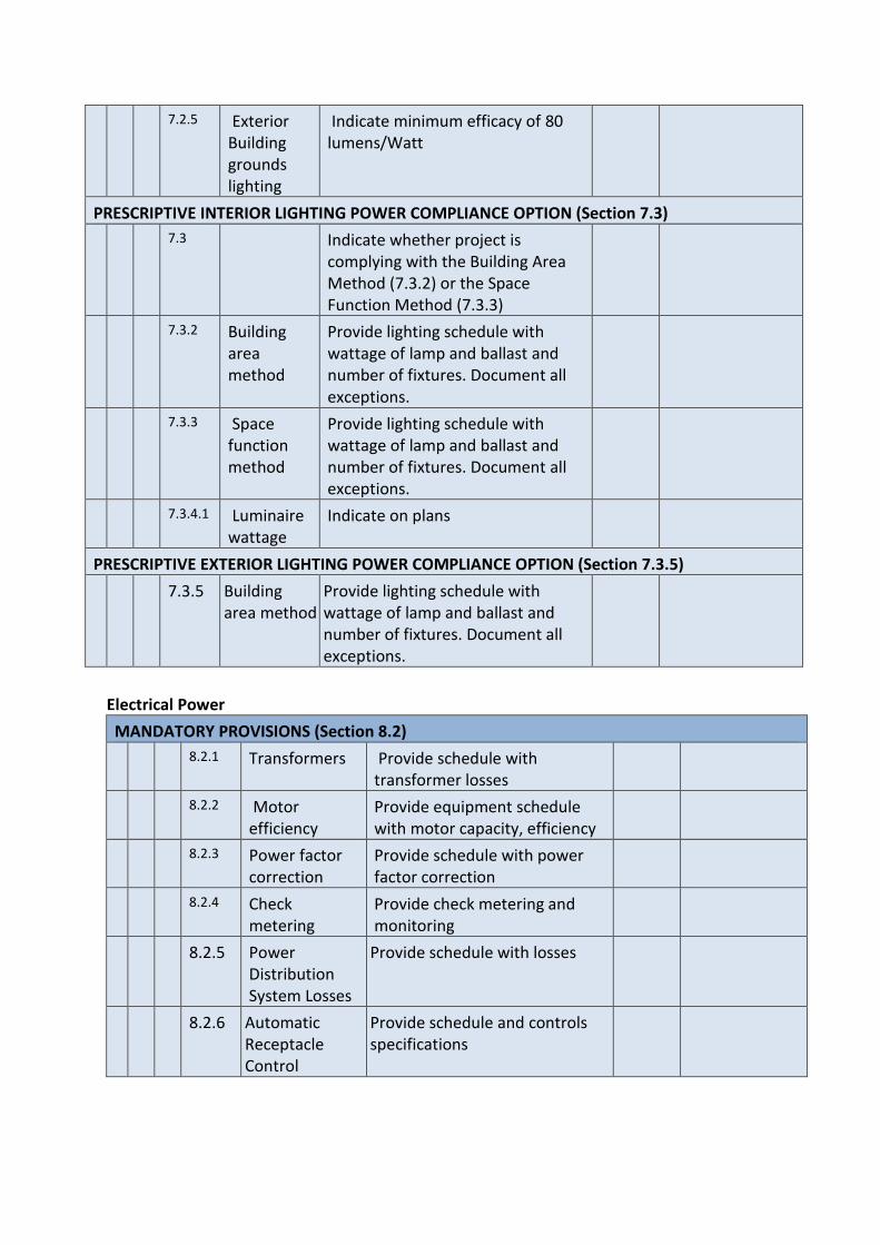
7.2.5 Exterior
Building
grounds
lighting
Indicate minimum efficacy of 80
lumens/Watt
PRESCRIPTIVE INTERIOR LIGHTING POWER COMPLIANCE OPTION (Section 7.3)
7.3 Indicate whether project is
complying with the Building Area
Method (7.3.2) or the Space
Function Method (7.3.3)
7.3.2 Building
area
method
Provide lighting schedule with
wattage of lamp and ballast and
number of fixtures. Document all
exceptions.
7.3.3 Space
function
method
Provide lighting schedule with
wattage of lamp and ballast and
number of fixtures. Document all
exceptions.
7.3.4.1 Luminaire
wattage
Indicate on plans
PRESCRIPTIVE EXTERIOR LIGHTING POWER COMPLIANCE OPTION (Section 7.3.5)
7.3.5 Building
area method
Provide lighting schedule with
wattage of lamp and ballast and
number of fixtures. Document all
exceptions.
Electrical Power
MANDATORY PROVISIONS (Section 8.2)
8.2.1 Transformers Provide schedule with
transformer losses
8.2.2 Motor
efficiency
Provide equipment schedule
with motor capacity, efficiency
8.2.3 Power factor
correction
Provide schedule with power
factor correction
8.2.4 Check
metering
Provide check metering and
monitoring
8.2.5 Power
Distribution
System Losses
Provide schedule with losses
8.2.6 Automatic
Receptacle
Control
Provide schedule and controls
specifications