Embed Size (px)
Citation preview
DECEMBER 14, 2016
ALBANY AVENUE (ROUTE 44) OPERATIONAL, SAFETY, AND
STREETSCAPE IMPROVEMENTS
FEDERAL AID PROJECT NO. 0044(139)
STATE PROJECT NOS. 0063-0633
CITY OF HARTFORD
ADDENDUM NO. 1
This Addendum addresses the following questions and answers contained on the “CT DOT QUESTIONS AND
ANSWERS WEBSITE FOR ADVERTISED CONSTRUCTION PROJECTS”:
Question and Answer Nos. 1-51.
SPECIAL PROVISION(S)
NEW SPECIAL PROVISION(S)
The following Special Provisions are hereby added to the Contract:
NTC – SOLE SOURCE PRODUCTS
NTC – JOB FAIR
0202452A – TEST PIT
0406002A – TEMPORARY PAVEMENT
2999998A - ON-THE-JOB TRAINING PROGRAM
REVISED SPECIAL PROVISION(S)
The following Special Provisions are hereby deleted in their entirety and replaced with the attached like-named
Special Provisions:
NOTICE TO CONTRACTOR – UTILITY GENERATED SCHEDULE
SECTION 1.08 – PROSECUTION AND PROGRESS
NTC – CATCH BASINS
NTC – PERMITS AND PERMIT FEES
NTC – PRECONSTRUCTION DOCUMENTATION
0201013A – REMOVAL OF EXISTING FENCE
0201215A – REMOVE AND RESET GATE
0202512A – CUT CONCRETE SIDEWALK
0202531A – REMOVAL OF BITUMINOUS CONCRETE
0205004A – ROCK IN TRENCH EXCAVATION 0’ – 10’ DEEP
0205006A – ROCK IN TRENCH EXCAVATION 0’ – 15’ DEEP
0404100A – BITUMINOUS CONCRETE PATCHING – FULL DEPTH
0406275A – FINE MILLING OF BITUMINOUS CONCRETE (0 TO 4 INCHES).
0406314A – 80 MIL PAVEMENT MARKING GROOVE 5” WIDE
0406316A – 80 MIL PAVEMENT MARKING GROOVE 9” WIDE
ADDENDUM NO.10063-0633 1
0507001A – TYPE “C” CATCH BASIN
0507006A – TYPE “C” CATCH BASIN TOP
0507018A – SPECIAL TYPE “C-L” CATCH BASIN TOP
0507022A – TYPE “C” CATCH BASIN DOUBLE GRATE – TYPE II
0507215A – SPECIAL TYPE “C-L” CATCH BASIN
0507758A – RESET MANHOLE (STORM)
0507771A – RESET CATCH BASIN
0507899A – OFFSET CATCH BASIN
0507900A – SPECIAL TRENCH DRAIN
0601192A – SURFACE PATCH
0651742A – 10” POLYVINYL CHLORIDE PIPE
0651745A – 8” POLYVINYL CHLORIDE PIPE
0651746A – 12” POLYVINYL CHLORIDE PIPE
0811005A – CONCRETE WHEEL STOP
0813055A – 8” X 20” GRANITE STONE CURBING
0813056A – 8” X 20” GRANITE STONE CURVED CURBING
0813455A – RADIAL GRANITE CURB DRIVEWAY RETURN
0901005A – BOLLARD
0913310A – REMOVE AND RESET DECORATIVE FENCE
0913838A – GATE
0914018A – ORNAMENTAL METAL FENCE (4’ HIGH)
0921018A – BRICK PAVING
0947207A – BICYCLE STAND
0947301A – REINFORCED CONCRETE BUS PAD
0947303A – BUS SHELTER – TYPE A
0947304A – BUS SHELTER – TYPE B
0949111A – PROTECTIVE FENCING
0950023A – LANDSCAPE EDGING
0992090A – BENCH
1002121A – ORNAMENTAL LIGHT POLE FOUNDATION
1003579A – 14’ ORNAMENTAL STREET LIGHT POLE ALUMINUM
1003580A – 28” ORNAMENTAL STREET LIGHT POLE ALUMINUM
1003612A – ORNAMENTAL ACCESSORY, BANNER ARMS
1003614A – ORNAMENTAL ACCESSORY, GROUND FAULT RECEPTACLE
1003615A – ORNAMENTAL ACCESSORY, PLANT HANGER
1003616A – STREET SIGN BRACKET FOR ORNAMENTAL LIGHT POLES
1003630A – ORNAMENTAL ACCESSORY, 6’ ORNAMENTAL BRACKET ARM
1003671A – ORNAMENTAL LUMINAIRE ROADWAY STYLE
1003672A – ORNAMENTAL LUMINAIRE HARTFORD STYLE
1003889A – REMOVE LIGHT POLE FOUNDATION 24” BELOW FINISHED PAVEMENT
SURFACEGRADE
1008187A – 4” PVC CONDUIT
1010055A – FIBER OPTIC HANDHOLE
1017033A – SERVICE CABINET
1102002A – 8’ ALUMINUM PEDESTAL
1108649A – ADVANCED TRANSPORTATION CONTROLLER MODEL 2070
1302051A – RESET VALVE BOX (WATER MAIN)
ADDENDUM NO.10063-0633 2
DELETED SPECIAL PROVISION(S)
The following Special Provisions are hereby deleted in their entirety:
NTC – TURF ESTABLISHMENT – LAWN
OJT PROVISION- ON-JOB- TRAINING (OJT) WORKFORCE DEVELOPMENT PILOT
SECTION M.13 – ROADSIDE DEVELOPMENT
0202451A – TEST PIT EXCAVATION
0507254A – TYPE “C” CATCH BASIN DOUBLE GRATE – TYPE II TOP
0507748A – RESET TYPE “C” CATCH BASIN DOUBLE GRATE – TYPE II
0507899A – SPECIAL OFFSET CATCH BASIN
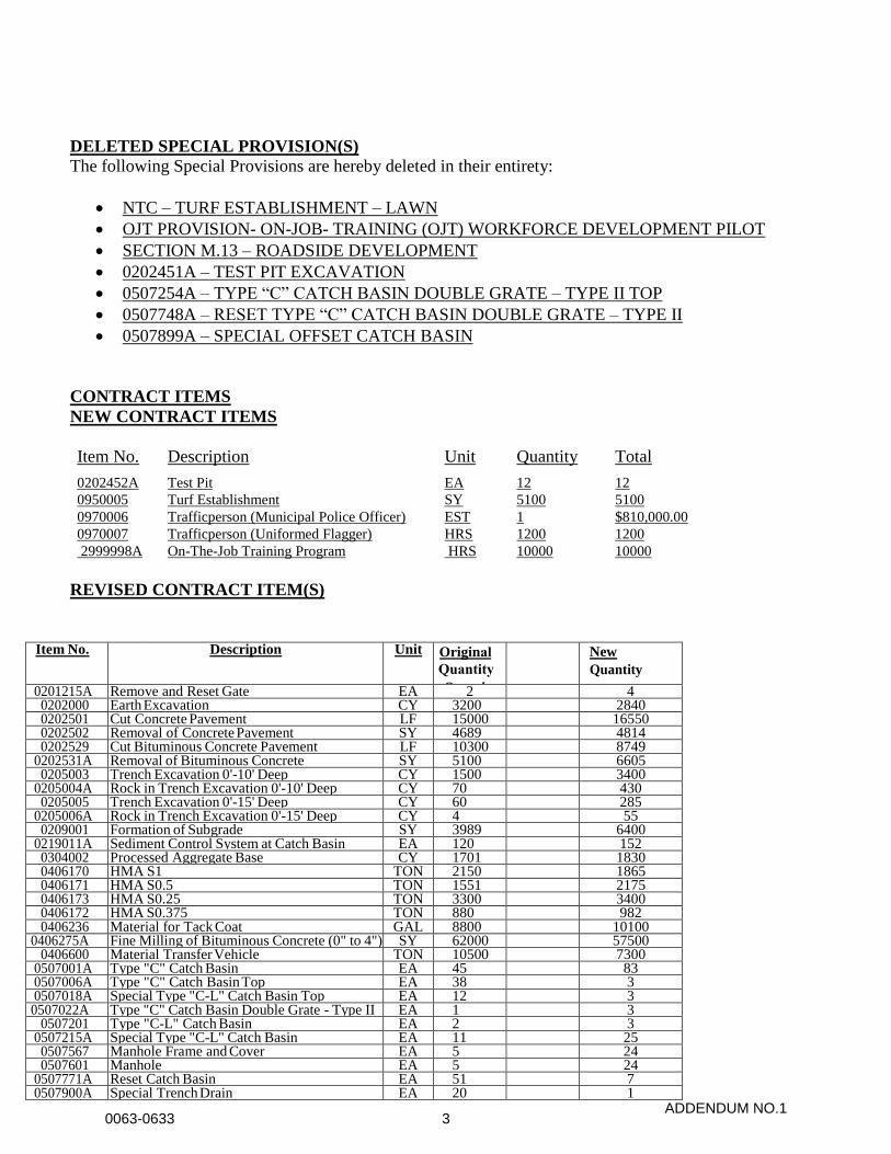
CONTRACT ITEMS
NEW CONTRACT ITEMS
Item No. Description Unit Quantity Total
0202452A Test Pit EA 12 12
0950005 Turf Establishment SY 5100 5100
0970006 Trafficperson (Municipal Police Officer) EST 1 $810,000.00
0970007 Trafficperson (Uniformed Flagger) HRS 1200 1200
2999998A
2999998
On-The-Job Training Program HRS 10000 10000
REVISED CONTRACT ITEM(S)
Item No. Description Unit OriginalQuantityQuanti
ty
New
Quantity
0201215A Remove and Reset Gate EA 2 4 0202000 Earth Excavation CY 3200 2840 0202501 Cut Concrete Pavement LF 15000 16550 0202502 Removal of Concrete Pavement SY 4689 4814 0202529 Cut Bituminous Concrete Pavement LF 10300 8749
0202531A Removal of Bituminous Concrete SY 5100 6605 0205003 Trench Excavation 0'-10' Deep CY 1500 3400
0205004A Rock in Trench Excavation 0'-10' Deep CY 70 430 0205005 Trench Excavation 0'-15' Deep CY 60 285
0205006A Rock in Trench Excavation 0'-15' Deep CY 4 55 0209001 Formation of Subgrade SY 3989 6400
0219011A Sediment Control System at Catch Basin EA 120 152 0304002 Processed Aggregate Base CY 1701 1830 0406170 HMA S1 TON 2150 1865 0406171 HMA S0.5 TON 1551 2175 0406173 HMA S0.25 TON 3300 3400 0406172 HMA S0.375 TON 880 982 0406236 Material for Tack Coat GAL 8800 10100
0406275A Fine Milling of Bituminous Concrete (0" to 4") SY 62000 57500 0406600 Material Transfer Vehicle TON 10500 7300
0507001A Type "C" Catch Basin EA 45 83 0507006A Type "C" Catch Basin Top EA 38 3 0507018A Special Type "C-L" Catch Basin Top EA 12 3 0507022A 0507022A
Type "C" Catch Basin Double Grate - Type II EA 1 3 0507201 Type "C-L" Catch Basin EA 2 3
0507215A Special Type "C-L" Catch Basin EA 11 25 0507567 Manhole Frame and Cover EA 5 24 0507601 Manhole EA 5 24
0507771A Reset Catch Basin EA 51 7 0507900A Special Trench Drain EA 20 1
ADDENDUM NO.10063-0633 3

DELETED CONTRACT ITEM(S)
Item No. Description Unit Original
Quantity New
Quantity 0202451A Test Pit Excavation CY 12 0 0507254A Type "C" Catch Basin Double Grate -
Type II Top
EA 2 0
0507748A Reset Type "C-L" Catch Basin Double Grate -
Type II
EA 2 0
0507831 Convert Catch Basin to Manhole EA 21 0 0950019 Turf Establishment - Lawn SY 4850 0 3000101 Trafficmen (State Police) LS 1 0
PLANS
NEW PLANS
The following Plan Sheets are hereby added to the Contract:
Drawing Title New Dwg. No. New Sheet No.
Revisions REV-02 02.002.A1
Miscellaneous Details MDS-07-1 03.017-1.A1
Cross Sections – Burton Street CRO-69 03.298.A1
Cross Sections – Burton Street CRO-70 03.299.A1
Cross Sections – Garden Street CRO-71 03.300.A1
Cross Sections – Garden Street CRO-72 03.301.A1
Cross Sections – Garden Street CRO-73 03.302.A1
REVISED PLAN(S)
The following Plan Sheets are hereby deleted and replaced with the like-numbered Plan Sheets:
DRAWING TITLE DWG. NO. SHEET NO
Legend, Abbreviations, & General Notes GNA-01 01.002.A1 Revisions REV-01 02.001.A1
Key Plan KEY-01 03.002.A1 Typical Sections TYP-01 03.004.A1 Typical Sections TYP-02 03.005.A1 Typical Sections TYP-03 03.006.A1 Typical Sections TYP-04 03.007.A1 Typical Sections TYP-05 03.008.A1
0813021A 6" Granite Stone Curbing LF 14100 16185 0815001 Bituminous Concrete Lip Curbing LF 1175 1425
0913310A Remove and Reset Decorative Fence LF 355 400 0944000 Furnishing and Placing Topsoil SY 4750 5100 0949000 Wood Chip Mulch SY 2000 2060 0949012 Hemerocallis SPP. Daylily 1 Gal. Cont. EA 128 541
ADDENDUM NO.10063-0633 4
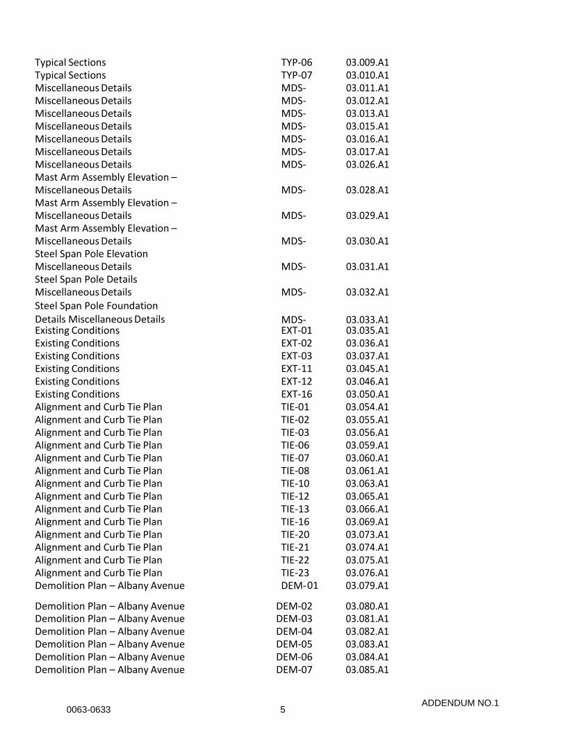
Typical Sections TYP-06 03.009.A1 Typical Sections TYP-07 03.010.A1 Miscellaneous Details MDS-
0103.011.A1
Miscellaneous Details MDS-02
03.012.A1 Miscellaneous Details MDS-
0303.013.A1
Miscellaneous Details MDS-05
03.015.A1 Miscellaneous Details MDS-
0603.016.A1
Miscellaneous Details MDS-07
03.017.A1 Miscellaneous Details MDS-
1603.026.A1
Mast Arm Assembly Elevation – Miscellaneous Details MDS-
1803.028.A1
Mast Arm Assembly Elevation – Miscellaneous Details MDS-
1903.029.A1
Mast Arm Assembly Elevation – Miscellaneous Details MDS-
2003.030.A1
Steel Span Pole Elevation Miscellaneous Details MDS-
2103.031.A1
Steel Span Pole Details Miscellaneous Details MDS-
2203.032.A1
Steel Span Pole Foundation Details Miscellaneous Details MDS-
2303.033.A1
Existing Conditions EXT-01 03.035.A1 Existing Conditions EXT-02 03.036.A1 Existing Conditions EXT-03 03.037.A1 Existing Conditions EXT-11 03.045.A1 Existing Conditions EXT-12 03.046.A1 Existing Conditions EXT-16 03.050.A1 Alignment and Curb Tie Plan TIE-01 03.054.A1 Alignment and Curb Tie Plan TIE-02 03.055.A1 Alignment and Curb Tie Plan TIE-03 03.056.A1 Alignment and Curb Tie Plan TIE-06 03.059.A1 Alignment and Curb Tie Plan TIE-07 03.060.A1 Alignment and Curb Tie Plan TIE-08 03.061.A1 Alignment and Curb Tie Plan TIE-10 03.063.A1 Alignment and Curb Tie Plan TIE-12 03.065.A1 Alignment and Curb Tie Plan TIE-13 03.066.A1 Alignment and Curb Tie Plan TIE-16 03.069.A1 Alignment and Curb Tie Plan TIE-20 03.073.A1 Alignment and Curb Tie Plan TIE-21 03.074.A1 Alignment and Curb Tie Plan TIE-22 03.075.A1 Alignment and Curb Tie Plan TIE-23 03.076.A1 Demolition Plan – Albany Avenue DEM-01 03.079.A1
Demolition Plan – Albany Avenue DEM-02 03.080.A1 Demolition Plan – Albany Avenue DEM-03 03.081.A1 Demolition Plan – Albany Avenue DEM-04 03.082.A1 Demolition Plan – Albany Avenue DEM-05 03.083.A1 Demolition Plan – Albany Avenue DEM-06 03.084.A1 Demolition Plan – Albany Avenue DEM-07 03.085.A1
ADDENDUM NO.10063-0633 5

Demolition Plan – Albany Avenue DEM-08 03.086.A1 Demolition Plan – Albany Avenue DEM-09 03.087.A1 Demolition Plan – Albany Avenue DEM-10 03.088.A1 Demolition Plan– Albany Avenue DEM-11 03.089.A1 Demolition Plan – Westbourne Parkway DEM-12 03.090.A1 Demolition Plan – Homestead Avenue DEM-13 03.091.A1 Demolition Plan – Blue Hills Avenue DEM-14 03.092.A1 Demolition Plan – Woodland Street DEM-15 03.093.A1 Demolition Plan – Woodland Street DEM-16 03.094.A1 Demolition Plan – Burton Street DEM-17 03.095.A1 Demolition Plan – Garden Street DEM-18 03.096.A1 Construction Plan – Albany Avenue PLN-01 03.097.A1 Construction Plan – Albany Avenue PLN-02 03.098.A1 Construction Plan – Albany Avenue PLN-03 03.099.A1 Construction Plan – Albany Avenue PLN-04 03.100.A1 Construction Plan – Albany Avenue PLN-05 03.101.A1 Construction Plan – Albany Avenue PLN-06 03.102.A1 Construction Plan – Albany Avenue PLN-07 03.103.A1 Construction Plan – Albany Avenue PLN-08 03.104.A1 Construction Plan – Albany Avenue PLN-09 03.105.A1 Construction Plan – Albany Avenue PLN-10 03.106.A1 Construction Plan – Albany Avenue PLN-11 03.107.A1 Construction Plan – Westbourne Parkway PLN-12 03.108.A1 Construction Plan – Homestead Avenue PLN-13 03.109.A1 Construction Plan – Blue Hills Avenue PLN-14 03.110.A1 Construction Plan – Woodland Street PLN-15 03.111.A1 Construction Plan – Woodland Street PLN-16 03.112.A1 Construction Plan – Burton Street PLN-17 03.113.A1 Construction Plan – Garden Street PLN-18 03.114.A1 Construction Plan – Albany Avenue PLN-19 03.115.A1 Construction Plan – Albany Avenue PLN-20 03.116.A1 Profile – Albany Avenue PRF-05 03.121.A1 Profile – Albany Avenue PRF-06 03.122.A1 Profile – Albany Avenue PRF-09 03.125.A1 Profile – Albany Avenue PRF-11 03.127.A1 Pavement Marking Plans PMP-01 03.137.A1 Pavement Marking Plans PMP-02 03.138.A1 Pavement Marking Plans PMP-03 03.139.A1 Pavement Marking Plans PMP-04 03.140.A1 Pavement Marking Plans PMP-05 03.141.A1 Pavement Marking Plans PMP-06 03.142.A1 Pavement Marking Plans PMP-07 03.143.A1
Pavement Marking Plans PMP-08 03.144.A1 Pavement Marking Plans PMP-09 03.145.A1 Pavement Marking Plans PMP-10 03.146.A1 Pavement Marking Plans PMP-11 03.147.A1 Pavement Marking Plans PMP-12 03.148.A1 Pavement Marking Plans PMP-13 03.149.A1
ADDENDUM NO.10063-0633 6
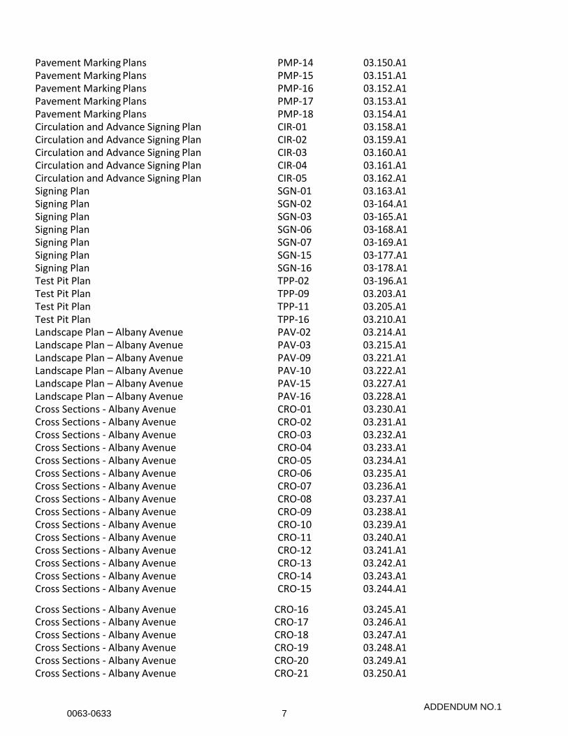
Pavement Marking Plans PMP-14 03.150.A1 Pavement Marking Plans PMP-15 03.151.A1 Pavement Marking Plans PMP-16 03.152.A1 Pavement Marking Plans PMP-17 03.153.A1 Pavement Marking Plans PMP-18 03.154.A1 Circulation and Advance Signing Plan CIR-01 03.158.A1 Circulation and Advance Signing Plan CIR-02 03.159.A1 Circulation and Advance Signing Plan CIR-03 03.160.A1 Circulation and Advance Signing Plan CIR-04 03.161.A1 Circulation and Advance Signing Plan CIR-05 03.162.A1 Signing Plan SGN-01 03.163.A1 Signing Plan SGN-02 03-164.A1 Signing Plan SGN-03 03-165.A1 Signing Plan SGN-06 03-168.A1 Signing Plan SGN-07 03-169.A1 Signing Plan SGN-15 03-177.A1 Signing Plan SGN-16 03-178.A1 Test Pit Plan TPP-02 03-196.A1 Test Pit Plan TPP-09 03.203.A1 Test Pit Plan TPP-11 03.205.A1 Test Pit Plan TPP-16 03.210.A1 Landscape Plan – Albany Avenue PAV-02 03.214.A1 Landscape Plan – Albany Avenue PAV-03 03.215.A1 Landscape Plan – Albany Avenue PAV-09 03.221.A1 Landscape Plan – Albany Avenue PAV-10 03.222.A1 Landscape Plan – Albany Avenue PAV-15 03.227.A1 Landscape Plan – Albany Avenue PAV-16 03.228.A1 Cross Sections - Albany Avenue CRO-01 03.230.A1 Cross Sections - Albany Avenue CRO-02 03.231.A1 Cross Sections - Albany Avenue CRO-03 03.232.A1 Cross Sections - Albany Avenue CRO-04 03.233.A1 Cross Sections - Albany Avenue CRO-05 03.234.A1 Cross Sections - Albany Avenue CRO-06 03.235.A1 Cross Sections - Albany Avenue CRO-07 03.236.A1 Cross Sections - Albany Avenue CRO-08 03.237.A1 Cross Sections - Albany Avenue CRO-09 03.238.A1 Cross Sections - Albany Avenue CRO-10 03.239.A1 Cross Sections - Albany Avenue CRO-11 03.240.A1 Cross Sections - Albany Avenue CRO-12 03.241.A1 Cross Sections - Albany Avenue CRO-13 03.242.A1 Cross Sections - Albany Avenue CRO-14 03.243.A1 Cross Sections - Albany Avenue CRO-15 03.244.A1
Cross Sections - Albany Avenue CRO-16 03.245.A1 Cross Sections - Albany Avenue CRO-17 03.246.A1 Cross Sections - Albany Avenue CRO-18 03.247.A1 Cross Sections - Albany Avenue CRO-19 03.248.A1 Cross Sections - Albany Avenue CRO-20 03.249.A1 Cross Sections - Albany Avenue CRO-21 03.250.A1
ADDENDUM NO.10063-0633 7
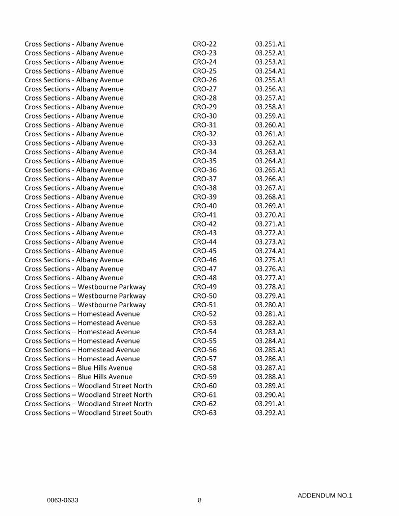
Cross Sections - Albany Avenue CRO-22 03.251.A1 Cross Sections - Albany Avenue CRO-23 03.252.A1 Cross Sections - Albany Avenue CRO-24 03.253.A1 Cross Sections - Albany Avenue CRO-25 03.254.A1 Cross Sections - Albany Avenue CRO-26 03.255.A1 Cross Sections - Albany Avenue CRO-27 03.256.A1 Cross Sections - Albany Avenue CRO-28 03.257.A1 Cross Sections - Albany Avenue CRO-29 03.258.A1 Cross Sections - Albany Avenue CRO-30 03.259.A1 Cross Sections - Albany Avenue CRO-31 03.260.A1 Cross Sections - Albany Avenue CRO-32 03.261.A1 Cross Sections - Albany Avenue CRO-33 03.262.A1 Cross Sections - Albany Avenue CRO-34 03.263.A1 Cross Sections - Albany Avenue CRO-35 03.264.A1 Cross Sections - Albany Avenue CRO-36 03.265.A1 Cross Sections - Albany Avenue CRO-37 03.266.A1 Cross Sections - Albany Avenue CRO-38 03.267.A1 Cross Sections - Albany Avenue CRO-39 03.268.A1 Cross Sections - Albany Avenue CRO-40 03.269.A1 Cross Sections - Albany Avenue CRO-41 03.270.A1 Cross Sections - Albany Avenue CRO-42 03.271.A1 Cross Sections - Albany Avenue CRO-43 03.272.A1 Cross Sections - Albany Avenue CRO-44 03.273.A1 Cross Sections - Albany Avenue CRO-45 03.274.A1 Cross Sections - Albany Avenue CRO-46 03.275.A1 Cross Sections - Albany Avenue CRO-47 03.276.A1 Cross Sections - Albany Avenue CRO-48 03.277.A1 Cross Sections – Westbourne Parkway CRO-49 03.278.A1 Cross Sections – Westbourne Parkway CRO-50 03.279.A1 Cross Sections – Westbourne Parkway CRO-51 03.280.A1 Cross Sections – Homestead Avenue CRO-52 03.281.A1 Cross Sections – Homestead Avenue CRO-53 03.282.A1 Cross Sections – Homestead Avenue CRO-54 03.283.A1 Cross Sections – Homestead Avenue CRO-55 03.284.A1 Cross Sections – Homestead Avenue CRO-56 03.285.A1 Cross Sections – Homestead Avenue CRO-57 03.286.A1 Cross Sections – Blue Hills Avenue CRO-58 03.287.A1 Cross Sections – Blue Hills Avenue CRO-59 03.288.A1 Cross Sections – Woodland Street North CRO-60 03.289.A1 Cross Sections – Woodland Street North CRO-61 03.290.A1 Cross Sections – Woodland Street North CRO-62 03.291.A1 Cross Sections – Woodland Street South CRO-63 03.292.A1
ADDENDUM NO.10063-0633 8
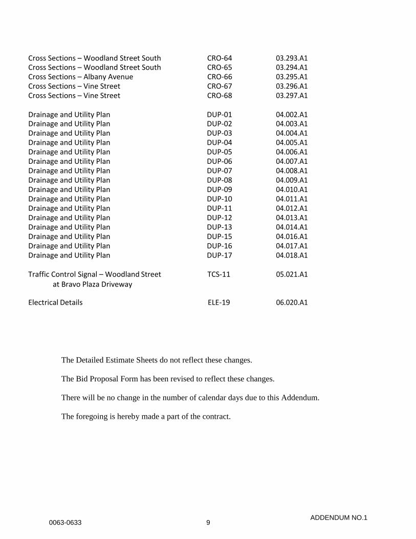
The Detailed Estimate Sheets do not reflect these changes.
The Bid Proposal Form has been revised to reflect these changes.
There will be no change in the number of calendar days due to this Addendum.
The foregoing is hereby made a part of the contract.
Cross Sections – Woodland Street South CRO-64 03.293.A1 Cross Sections – Woodland Street South CRO-65 03.294.A1 Cross Sections – Albany Avenue CRO-66 03.295.A1 Cross Sections – Vine Street CRO-67 03.296.A1 Cross Sections – Vine Street CRO-68 03.297.A1
Drainage and Utility Plan DUP-01 04.002.A1 Drainage and Utility Plan DUP-02 04.003.A1 Drainage and Utility Plan DUP-03 04.004.A1 Drainage and Utility Plan DUP-04 04.005.A1 Drainage and Utility Plan DUP-05 04.006.A1 Drainage and Utility Plan DUP-06 04.007.A1 Drainage and Utility Plan DUP-07 04.008.A1 Drainage and Utility Plan DUP-08 04.009.A1 Drainage and Utility Plan DUP-09 04.010.A1 Drainage and Utility Plan DUP-10 04.011.A1 Drainage and Utility Plan DUP-11 04.012.A1 Drainage and Utility Plan DUP-12 04.013.A1 Drainage and Utility Plan DUP-13 04.014.A1 Drainage and Utility Plan DUP-15 04.016.A1 Drainage and Utility Plan DUP-16 04.017.A1 Drainage and Utility Plan DUP-17 04.018.A1
Traffic Control Signal – Woodland Street at Bravo Plaza Driveway
TCS-11 05.021.A1
Electrical Details ELE-19 06.020.A1
ADDENDUM NO.10063-0633 9

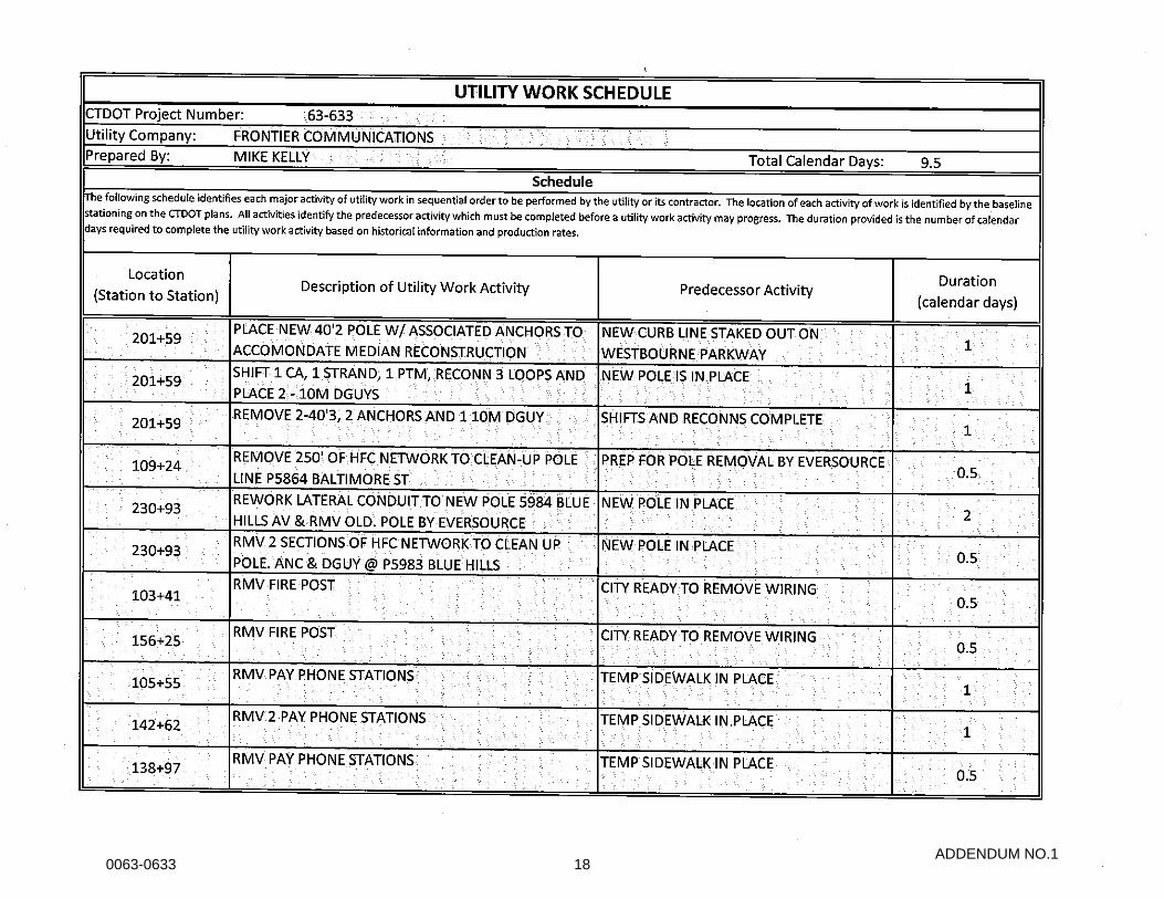
NOTICE TO CONTRACTOR – UTILITY GENERATED SCHEDULE
The attached project specific utility work schedule was provided to the Connecticut Department
of Transportation (Department) by the utility companies regarding their identified work on this
project.
The utility scheduling information is provided to assist the Contractor in scheduling its activities.
However, the Department does not ensure its accuracy and Section 1.05.06 of the Standard
Specifications still is in force.
The utility scheduling information shall be incorporated into the Contractor’s pre-award schedule
in accordance with the Department’s Bidding and Award Manual and Section 1.05.08 of the
Contract.
After award, the Contractor shall conduct a utility coordination meeting or meetings to obtain
contemporaneous scheduling information from the utilities prior to submitting its baseline
schedule to the Department in accordance with Section (1.05.08 – Schedules and Reports) of the
Contract.
The Contractor shall incorporate the contemporaneous utility scheduling information into its
baseline schedule submittal. The baseline schedule shall include Contractor predecessor and
successor activities to the utility work in such detail as acceptable to the Engineer.
ADDENDUM NO.10063-0633 10

CTDOT Project Number: Town:
Project Description:
CTDOT Utilities Engineer:
Phone: Email:
Utility Company:
Prepared By: Date Prepared:
Phone: Email:
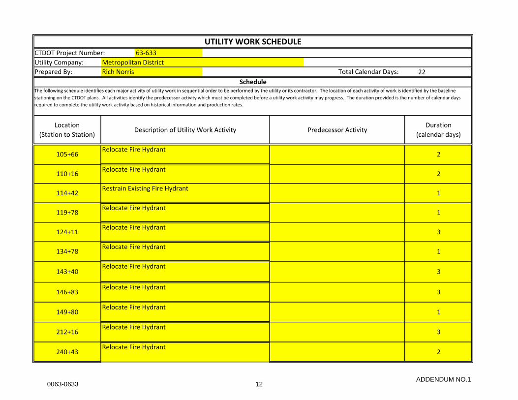
rev. 5/20/2013 UTILITY WORK SCHEDULE
Scope of Work
Special Considerations and Constraints
(860) 594-2555
Metropolitan District
Rich Norris
(860) 278-7850 x3450
63-633
Albany Avenue Safety and Streetscape Improvements
Derek Brown
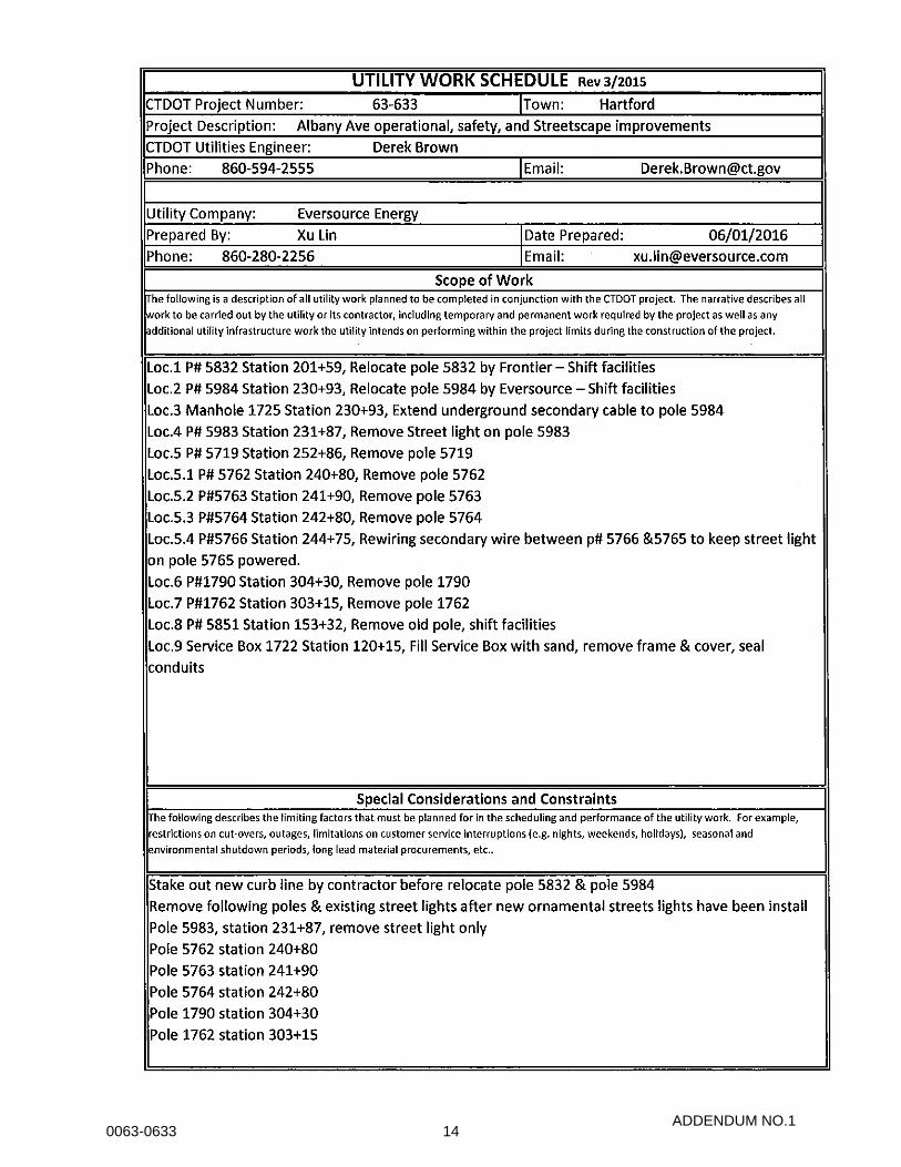
The following is a description of all utility work planned to be completed in conjunction with the CTDOT project. The narrative describes all
work to be carried out by the utility or its contractor, including temporary and permanent work required by the project as well as any
additional utility infrastructure work the utility intends on performing within the project limits during the construction of the project.
Hartford
8/30/2016
MDC forces to relocate and restrain fire hydrants within project limits.
The following describes the limiting factors that must be planned for in the scheduling and performance of the utility work. For example,
restrictions on cut-overs, outages, limitations on customer service interruptions (e.g. nights, weekends, holidays), seasonal and
environmental shutdown periods, long lead material procurements, etc..
ADDENDUM NO.10063-0633 11
CTDOT Project Number:
Utility Company:
Prepared By: 22
2
2
1
1
3
1
3
3
1
3
2240+43
Relocate Fire Hydrant
Relocate Fire Hydrant
Restrain Existing Fire Hydrant
Relocate Fire Hydrant
Relocate Fire Hydrant
Relocate Fire Hydrant
Relocate Fire Hydrant
Relocate Fire Hydrant
Relocate Fire Hydrant
Relocate Fire Hydrant
Relocate Fire Hydrant
134+78
143+40
146+83
149+80
212+16
105+66
110+16
114+42
119+78
124+11
UTILITY WORK SCHEDULE
Location
(Station to Station)Description of Utility Work Activity
Duration
(calendar days)Predecessor Activity
63-633
Rich Norris
Metropolitan District
ScheduleThe following schedule identifies each major activity of utility work in sequential order to be performed by the utility or its contractor. The location of each activity of work is identified by the baseline
stationing on the CTDOT plans. All activities identify the predecessor activity which must be completed before a utility work activity may progress. The duration provided is the number of calendar days
required to complete the utility work activity based on historical information and production rates.
Total Calendar Days:
ADDENDUM NO.10063-0633 12
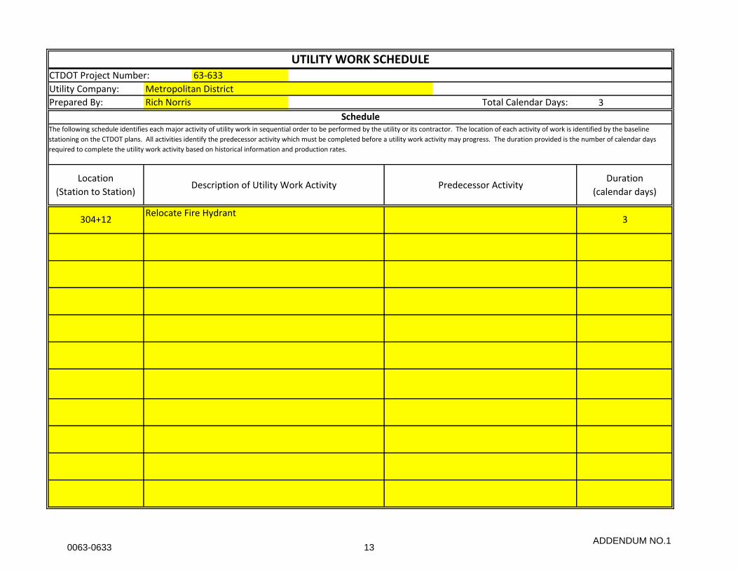
CTDOT Project Number:
Utility Company:
Prepared By: 3
304+12Relocate Fire Hydrant
3
UTILITY WORK SCHEDULE63-633
Metropolitan District
Rich Norris Total Calendar Days:
ScheduleThe following schedule identifies each major activity of utility work in sequential order to be performed by the utility or its contractor. The location of each activity of work is identified by the baseline
stationing on the CTDOT plans. All activities identify the predecessor activity which must be completed before a utility work activity may progress. The duration provided is the number of calendar days
required to complete the utility work activity based on historical information and production rates.
Location
(Station to Station)Description of Utility Work Activity Predecessor Activity
Duration
(calendar days)
ADDENDUM NO.10063-0633 13
ADDENDUM NO.10063-0633 14

ADDENDUM NO.10063-0633 15
ADDENDUM NO.10063-0633 16
ADDENDUM NO.10063-0633 17
ADDENDUM NO.10063-0633 18
ADDENDUM NO. 1
NOTICE TO CONTRACTOR – CATCH BASINS
The Contractor shall ensure that trap hoods are installed on all pipes exiting catch basins within
the project limits. The cost associated with this work shall be considered incidental to the project
and should be included in the bid price for the other drainage items.
The Contractor shall assume that all new catch basins and new manholes will be required to be
constructed from block/brick and not precast units due to conflicts/constraints with existing
infrastructure and pipe configuration. The Contractor may submit, on a case by case basis, partial
or full use of precast section for approval by the Engineer. The size and configuration of the
structures shall be as approved by the Engineer. The work shall be measured and paid for under
the established pay items for catch basins and manholes of the type specified.
The Contractor shall assume that all existing catch basins are nonstandard, small, round
block/brick structures. Furthermore, it shall be assumed that all existing structures will require
conversion/modifications in order to support a new catch basin top or to reset the existing catch
basin top. The work associated with the conversion of the existing catch basin structures shall be
as approved by the Engineer and the cost associated with the conversion/modification shall be
included in the bid price for the new or reset catch basin top of the type specified.
New catch basins or manholes installed along curb lines in close proximity to existing utilities may
require shifting the structure while maintaining the location of the top slab to prevent conflicts.
This work shall be performed at no additional cost.
0063-0633 19
GENERAL
ADDENDUM NO. 1
NOTICE TO CONTRACTOR – JOB FAIR
This project may require that the contractor participate in a career fair within the project area. As
part of the career fair, the contractor will be required to provide appropriate staff, (preferably a
Human Resources representative.)
The Connecticut Department of Transportation’s Office of Contract Compliance will work with
the contractor on the planning, location, duration, and outreach of the career fair.
There is no direct pay item for the Job Fair, and it shall be considered included in the general cost
of the work.
0063-0633 20

ADDENDUM NO. 1
NOTICE TO CONTRACTOR - PERMITS AND PERMIT FEES
It is the Contractor’s responsibility to obtain and pay for all required Federal, State, City and Utility
permits applicable to this project.
The Contractor shall contact MDC a minimum of 48 hours in advance of any drainage work being
performed. The Contractor shall obtain a Stormwater Connection permit from the MDC for each
of the catch basins within the project limits. Any costs incurred in order to obtain the permits shall
be included in the overall cost of the project.
Any field modifications to the proposed drainage during construction must be reviewed and
approved by the MDC.
The Contractor shall coordinate with the MDC with regards to the means and methods of
construction when working in the vicinity of any MDC water lines.
MDC must be present when any work is being performed on the drainage improvements for the
project unless a specific written waiver is supplied by the MDC on a case by case basis.
0063-0633 21
ADDENDUM NO. 1
NOTICE TO CONTRACTOR – PRECONSTRUCTION
DOCUMENTATION
The Contractor is hereby notified and advised that as a condition of this project he shall provide
pre-construction documentation of the project site. Ground photography shall consist of color
video taping of surface features taken along the entire length of the project and including all work
and storage areas and all intersecting roadways. Prior to audio-video taping of the project, all areas
to be inventoried shall be investigated visually with notations made of items not readily visible by
taping methods. The cost associated with this work shall be included in the lump sum bid for
“Mobilization & Project Closeout”.
The Contractor shall submit the following for approval in accordance with Conditions of Contract.
Video equipment specifications:
A. Pre-Construction Recording
Prior to the delivery of any equipment, materials or supplies to the site of any work, or to the
beginning of any of the construction work, the Contractor shall provide pre-construction
photography as specified herein for the purpose of establishing the surface conditions existing in
all of the areas to be affected by the construction.
Purpose of Video Taping: The purpose of the color audio-video taping of the project is to provide
the necessary information for restoration of surface features after completion of the project. The
Contractor shall be responsible for repairing any damage or defect not documented as existing
prior to construction.
B. Video Photography
Coverage of Taping: Such coverage shall include, but not be limited to, all existing driveways,
sidewalks, curbs, streets, signs, landscaping, trees, catch basins, fences, visible utilities and all
buildings located within the limits of construction. Of particular concern are any existing faults,
fractures, defects or other features. Audio description shall be made simultaneously with and
support the video coverage.
Streets – shall be recorded by audio-video DVD for the full width of the right-of-way, those areas
outside the right-of-way but within the limits of construction, and where specifically noted
otherwise by the Engineer.
Work Agreement Areas – shall be recorded by audio-video DVD including all adjacent areas lying
within the limits of construction as directed by the Engineer. The size and locations of all areas to
be taped will be shown on the Plans or otherwise supplied by the Engineer.
Front and/or Side yard Areas – of residential homes within the zone of influence of construction
shall be recorded.
0063-0633 22
ADDENDUM NO. 1
C. Equipment
Video – Color audio-video shall be DVD format.
D. Location Information
All DVD’s shall be properly identified by number, location and project name in a manner
acceptable to the Engineer.
A record of the contents of each DVD shall be supplied on a run sheet identifying each segment
in the tape by location, i.e., street viewing side, traveling direction, engineering stationing, and all
referenced by tape counter numbers.
All video recordings shall begin with the date and time of recording, the project name, the sheet
numbers of engineering stationing as shown on the plans, the name of the street, area or building
being taped, the direction of travel and the viewing side. Houses and buildings shall be identified
visually by house or building address, when possible, in such manner that the progress of the taping
and the proposed system may be located by reference to the houses and buildings.
E. Entering Private Property
If it becomes necessary to enter onto private property, notify the owner of such property at least
24 hours in advance of the planned entry to obtain his permission to do so. Should the owner of
the property refuse to give his permission for said entry, notify the Engineer.
The Contractor is advised that he shall not enter any private property before permission is granted
to do so, or the Engineer notified by the Contractor that he has gained the legal right to do so. The
Contractor shall be held liable for entry made other than stated herein.
F. Ownership of Recordings
All DVD’s produced will become the permanent property of the State of Connecticut. The
Contractor shall deliver all tapes to the Engineer prior to the beginning of any construction work.
Any portion of the DVD coverage deemed unacceptable by the Engineer must be re-taped by the
Contractor at no additional charge to the State of Connecticut.
G. Site Recording Conditions
All taping shall be done during times of good visibility. No outside taping shall be done during
periods of visible precipitation or when the ground area is covered with snow, leaves or debris,
unless otherwise authorized by the Engineer.
In order to produce the proper detail and perspective, adequate auxiliary lighting will be required
to fill in shadow areas caused by trees, utility poles, road signs and other such objects, as well as
other conditions requiring artificial illumination.
0063-0633 23

ADDENDUM NO. 1
The average rate of speed in the general direction of travel of the conveyance used during taping
shall not exceed 60 feet per minute. Planning rates and zoom-out rates shall be controlled
sufficiently so that playback will produce adequate clarity of the object being viewed.
When conventional wheeled vehicles are used as conveyances for the taping, the distance from the
camera lens to the ground shall be such as to ensure proper perspective. In instances where tape
coverage will be required in areas not accessible to conventional wheeled vehicles, such coverage
shall be obtained by walking or by special conveyance approved by the Engineer but with the same
requirements for tape quality and content as specified herein, except as may be specifically
exempted by the Engineer.
0063-0633 24
ADDENDUM NO. 1
NOTICE TO CONTRACTOR – SOLE SOURCE PRODUCTS
For operational purposes, the Department has determined the need to sole source products
specified in the following Contract provisions.
Item 0947303A – Bus Shelter – Type A
Item 0947304A – Bus Shelter – Type B
Item 0992090A – Bench
Item 0992103A- Trash Can
Item 1003616A – Street Sign Brackets for Ornamental Light Poles
Item 1010039A – Precast Polymer Concrete Handhole Type II (17” x 30”)
Item 1208996A – Metal Sign Posts
No “Or Equals” will be permitted. Said products shall be installed only by their factory authorized
installer or service representative.
The Contractor shall bid the project accordingly.
0063-0633 25
Section 1.08
ADDENDUM NO. 1
SECTION 1.08 - PROSECUTION AND PROGRESS
Article 1.08.03 – Prosecution of Work:
Add the following:
The project will be constructed in various phases as described herein.
Phase I – Organization Phase up to (45) Calendar Days.
The first phase is to afford the Contractor time for the administrative/engineering/procurement
function required for the project. This would include such items as performing construction
staking, digging test pits, submitting catalog cuts or shop drawings and purchasing materials.
Actual construction is not permitted during the phase 1 unless approved by the Engineer. The
Contractor is to use this time to fully prepare for the successive phases so that construction can
proceed quickly and efficiently. During the phase, after the construction staking is complete and
underground utilities are marked out the Contractor, the designer and the Engineer will walk the
project to determine if there are test pits necessary or if there are any apparent conflicts with
private property, utilities, or other roadside appurtenances such as obstructions, rocks, large
trees, etc. Those conflicts will be resolved prior to ordering equipment for the specific area
where the conflict exits.
Phase 2 – Construction Phase
Phase 2 will not start prior to the conclusion of Phase 1, without the written permission of the
Engineer.
When all apparent conflicts have been identified and resolved, and written commitments have
been received from suppliers that all equipment and materials will be received within 30 days,
the Contractor may request that the construction phase begin. Once commencement of
construction begins, as and when approved by the Engineer, the Contractor will have the
remaining contract calendar days to complete the work, including cleanup. That work, once
started, must be completed within the time established for the original contract and liquidated
damages, as specified elsewhere in the Contract, will be assessed against the Contractor per
calendar day from that day until the date on which the work is complete. If unforeseen situations
arise, the Contractor may request an extension of time for an individual location and, if justified,
the Engineer may grant an extension of time for that location. Granting an extension of time for
one location will not entitle the Contractor to extensions of time for other locations in the project.
0063-0633 26
Section 1.08
ADDENDUM NO. 1
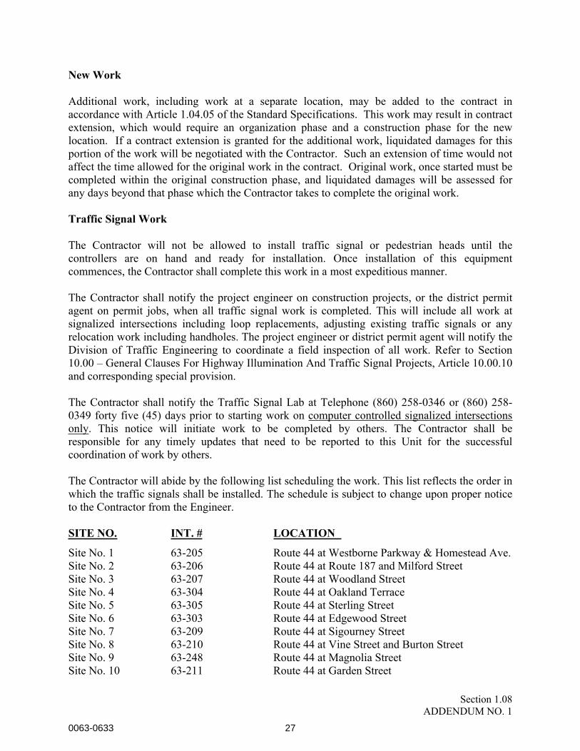
New Work
Additional work, including work at a separate location, may be added to the contract in
accordance with Article 1.04.05 of the Standard Specifications. This work may result in contract
extension, which would require an organization phase and a construction phase for the new
location. If a contract extension is granted for the additional work, liquidated damages for this
portion of the work will be negotiated with the Contractor. Such an extension of time would not
affect the time allowed for the original work in the contract. Original work, once started must be
completed within the original construction phase, and liquidated damages will be assessed for
any days beyond that phase which the Contractor takes to complete the original work.
Traffic Signal Work
The Contractor will not be allowed to install traffic signal or pedestrian heads until the
controllers are on hand and ready for installation. Once installation of this equipment
commences, the Contractor shall complete this work in a most expeditious manner.
The Contractor shall notify the project engineer on construction projects, or the district permit
agent on permit jobs, when all traffic signal work is completed. This will include all work at
signalized intersections including loop replacements, adjusting existing traffic signals or any
relocation work including handholes. The project engineer or district permit agent will notify the
Division of Traffic Engineering to coordinate a field inspection of all work. Refer to Section
10.00 – General Clauses For Highway Illumination And Traffic Signal Projects, Article 10.00.10
and corresponding special provision.
The Contractor shall notify the Traffic Signal Lab at Telephone (860) 258-0346 or (860) 258-
0349 forty five (45) days prior to starting work on computer controlled signalized intersections
only. This notice will initiate work to be completed by others. The Contractor shall be
responsible for any timely updates that need to be reported to this Unit for the successful
coordination of work by others.
The Contractor will abide by the following list scheduling the work. This list reflects the order in
which the traffic signals shall be installed. The schedule is subject to change upon proper notice
to the Contractor from the Engineer.
SITE NO. INT. # LOCATION
Site No. 1 63-205 Route 44 at Westborne Parkway & Homestead Ave.
Site No. 2 63-206 Route 44 at Route 187 and Milford Street
Site No. 3 63-207 Route 44 at Woodland Street
Site No. 4 63-304 Route 44 at Oakland Terrace
Site No. 5 63-305 Route 44 at Sterling Street
Site No. 6 63-303 Route 44 at Edgewood Street
Site No. 7 63-209 Route 44 at Sigourney Street
Site No. 8 63-210 Route 44 at Vine Street and Burton Street
Site No. 9 63-248 Route 44 at Magnolia Street
Site No. 10 63-211 Route 44 at Garden Street
0063-0633 27

Section 1.08
ADDENDUM NO. 1
Site No. 11 63-TBD Woodland Street at Bravo Plaza Drive
Site No. 12 63-302 Route 44 at Kent Street
Article 1.08.04 – Limitations of Operations – Add the following:
In order to provide for traffic operations as outlines in the Special Provision “Maintenance and
Protection of Traffic,” the Contractor will not be allowed to perform any work which will
interfere with existing traffic operations as specified herein.
General
The Contractor shall adhere to all the Limitations of Operations stated herein. All requested
modification/exceptions to these Limitations shall be submitted to the Engineer a minimum of
one week in advance of the work being performed and must receive written approval by the
Engineer, CTDOT and the City. Should the Contractor fail to comply with these limitations, the
Engineer shall order an immediate stop work until such time the Contractor does comply. There
will be no additional cost should such a stop work be issued. Should at any time the Engineer
determines that the work is severely impacting traffic, the Contractor shall be responsible for
altering the traffic pattern and work zone to alleviate the traffic issues. This effort shall be
included in the lump sum price bid for Maintenance and Protection of Traffic.
The Contactor will not be allowed to perform any work that will interfere with existing traffic
operations on all project roadways as detailed in the Circulation Signing and Pavement Marking
Plans.
The Contractor shall also be responsible for maintaining compliance with any additional
stipulations/restrictions included in the permit that the Contractor must obtain from the City of
Hartford and/or CTDOT.
Hours of Work
Work under this contract will be allowed from 7:00 am to 5:00 pm Monday through Friday. No
work will be allowed outside these work hours without written approval from CTDOT and the
City except milling and paving operations as noted below.
Coordination with City of Hartford
The Contractor is advised that events are held throughout the year in the City of Hartford. The
Contractor shall be responsible for coordinating his efforts with the City’s Department of
Development Services to ensure that construction operations do not adversely affect events.
As directed by the Engineer, the Contractor shall leave the work area in a neat and orderly
fashion so as to not disrupt any scheduled event.
The Contractor shall coordinate with and obtain regular updates for special events from the
following sources:
0063-0633 28

Section 1.08
ADDENDUM NO. 1
City of Harford Department of Development Services
Marian Andoh – Special Events Coordinator
Phone: 860-757-9526
Upper Albany Main Street
Marilyn Risi – Executive Director
Phone: 860-768-5742
http://www.hartford.com/events/
Work Zone
The Contractor will be restricted to a length of work zone of one block or 750 feet whichever is
shorter. The Contractor will be restricted from working on both sides of the roadway at the same
time.
Albany Avenue (Route 44)/Blue Hills Avenue (Route 187)
During the work hours from 7:00 am to 9:00 am and 3:00 pm to 5:00 pm the Contractor shall not
restrict traffic flow or utilize temporary traffic patterns. Secondary operations will be allowed,
provided the work is restricted to parking lanes and sidewalk areas and have no impact to traffic.
During the work hours from 9:00 am to 3:00 pm the Contractor shall provide/maintain a
minimum of a single 11 foot wide travel lane and turning lanes in each direction at all times.
All Other Roadways
During the work hours from 7:00 am to 9:00 am and 3:00 pm to 5:00 pm the Contractor shall
provide/maintain a minimum of a single 11 foot wide travel lane in each direction at all times.
During the work hours from 9:00 am to 3:00 pm the Contractor shall be allowed to reduce the
roadway width to provide a single 12 foot wide lane for alternating traffic.
Commercial and Residential Driveways
Access and egress to all adjacent properties shall be maintained at all times at no additional cost.
All temporary connections to abutting driveways and existing roadways must be accomplished in
a satisfactory manner, as determined by the Engineer, prior to the end of the work day/night at no
additional cost.
Road Closure
The Contractor will not be allowed to close any roads during the prosecution of work on this
contract unless specifically indicated otherwise on the plans or in the specifications. All roads
0063-0633 29

Section 1.08
ADDENDUM NO. 1
within the project limits shall be open to minimum two-way traffic after work hours. Detours
shall not be allowed during any holiday period as specified in the special provision Section
1.08.04-Prosecution and Progress-Limit of Operations.
Should the Contractor want to close a road or detour traffic, the Contractor must submit a request
to CTDOT, City of Hartford, and emergency service providers that will be affected by the detour
at least two weeks prior to initiating the detour. The Contractor must receive written approval
from all parties prior to initiating any detour.
Pedestrian Access
A dedicated ADA accessible sidewalk shall be maintained and protected to allow for the safe
passage of pedestrians during all construction phases at no additional cost. The Contractor is
responsible for providing a safe and accessible route to all curb ramps and pedestrian push
buttons during all construction phases at no additional cost. The Contractor may detour or
otherwise restrict pedestrian traffic if required for safety or other reasons, as approved by the
Engineer. The Contractor is responsible for providing any additional signage, barricades, and
police protection needed, as determined by the Engineer, to provide a safe accessible pedestrian
route. The Contractor must also maintain pedestrian access and egress to all adjacent properties,
businesses, and residences at all times though the construction area at no additional cost.
Milling and Paving
Milling and paving operations will be required to be completed during night time operations
between the hours of 9:00 PM and 5:00 AM Sunday through Thursday. Milling and paving
operations will not be allowed to run concurrently.
The Contractor shall schedule the operations so that pavement milling and/or re-paving
operations shall be full width across the roadway section at the end of the work day/work night.
If after milling the bituminous overlay, the exposed surface of the remaining bituminous concrete
pavement is deemed by the Engineer to be unsafe for travel due to severe surface deterioration,
the Contractor must immediately ensure a clear roadway, free from debris through seeping,
followed by patching the roadway with bituminous concrete.
The Contractor shall perform the milling of existing pavement, and the installation of the new
bituminous concrete pavement in accordance with the Special Provisions as contained elsewhere
in the contract documents.
Roadways will not be allowed to be left with an exposed milled surface for greater than 48 hours
unless specific written authorization has been requested from and provided by the Engineer. If
said roadways do not receive at least the 1” leveling course within the specified 48 hour limit, the
Engineer shall notify the Contractor of the deficient condition and the Contractor shall cease all
other construction activities until the subject roadway is properly prepared and the specified
overlays completed. Any damage to the milled surface after the 48 hour limit shall be repaired at
0063-0633 30

Section 1.08
ADDENDUM NO. 1
the Contractors expense and to the satisfaction of the Engineer, including but not limited to
additional partial depth patching, leveling courses, concrete base patching, etc.
All traverse height differentials on all roadway surfaces shall be tapered to negate any “bump” to
traffic as specified elsewhere in this contract or as approved by the Engineer. Material for this
taper shall be approved by the Engineer.
0063-0633 31

Section 1.08
ADDENDUM NO. 1
Signing, Pavement Markings, and Traffic Control
The Contractor shall implement the traffic patterns in accordance with the Specification
“Maintenance and Protection of Traffic.” Before opening to traffic, the Contractor shall backfill
and plate any area of the roadway disturbed by construction below the existing base course so
that an acceptable even travel surface can be provided.
Signing and striping patterns for lane closures shall follow the Traffic Control Plans provided in
the Specification “Maintenance and Protection of Traffic.”
No roadway shall be open to traffic unless the appropriate temporary or permanent pavement
markings have been installed. Areas where traffic is running on an unpaved surface shall be
delineated in an appropriate manner.
All temporary barriers, other protective systems and traffic control devices as called for by the
contract or ordered by the Engineer must be on-hand and available in sufficient quantity for
immediate installation prior to any stage change.
Traffic Signals
The signal shall be placed back in operation, using whatever combination of existing, proposed
and temporary signals are appropriate to maintain a proper signal display and visibility. The
proposed signal layout must be submitted to the Engineer for approval prior to implementation.
Loop detectors disturbed by the Contractor’s operation shall be made operational or temporary
detection must be provided within 24 hours of the termination of the existing loop detectors
0063-0633 32

ITEM # 0201013A
ADDENDUM NO. 1
ITEM # 0201013A – REMOVAL OF EXISTING FENCE
Description: Work under this item shall consist of the removal and disposal of the existing chain
link, metal, decorative, or wood fence and associated gates as shown on the plans, or as ordered
by the Engineer. Any existing gates that are within the sections of fence to be removed shall also
be removed and disposed of properly.
Construction Methods: The Contractor shall notify the adjacent property owners a minimum of
14 days in advance of their work operations.
Method of Measurement: Fence removed will be measured for payment by the number of linear
feet of fence removed and disposed of satisfactorily. Similarly, the removal of gates shall be
measured for payment by the number of linear feet of gate removed and disposed of satisfactorily.
Basis of Payment: Removal of chain link, metal, decorative, or wood fence, and associated gates,
will be paid for at the contract unit price per foot for “Removal of Existing Fence” which price
shall include all materials, equipment, tools, excavation, removal and disposal of foundations,
backfill, disposal of surplus material, and labor incidental to removing the existing fence and gates.
Pay Item Pay Unit
Removal of Existing Fence LF
0063-0633 33

ITEM # 0202452A
ADDENDUM NO. 1
ITEM # 0202452A – TEST PIT
Description: Excavate and backfill a designated area to determine the exact location of utility
facilities which are near a proposed foundation.
Materials:
Materials shall conform to the following:
Compacted Granular Fill: Article M.02.02
Bituminous Concrete Materials: Article M.04
Construction Methods:
Keep affected utility owner apprised of proposed test pit excavation.
Excavate only as authorized and as directed by the Engineer. The size, depth, and location will be
as authorized by the Engineer.
If rock greater than 0.5 c.y. (cu.m) is encountered, the Engineer will determine if it must be
removed and the method. Do not use explosives. See the pertinent construction methods of Section
2.02.03. When concrete must be removed, reinforced or not, it shall be considered, measured, and
paid for as rock in foundation excavation.
If unsuitable backfill material is excavated, dispose as directed by the Engineer. Replace with
suitable backfill and compact in accordance with Section 2.14.
Repair all damaged bituminous pavement in accordance with Section 4.06.03. Sawcut the edges
to neat lines if there will be no subsequent excavation at the test pit for a foundation.
Method of Measurement: Test pits will be measured at the contract unit price per each for the
material actually removed from within the limits specified as directed by the Engineer.
When necessary, rock in foundation excavation will be measured at the contract price per vertical
foot (vertical meter) for the rock actually removed in accordance with Article 2.02.04.
Basis of Payment: This work will be paid for at the contract unit price per each for “Test Pit”,
which price shall include excavation, unsuitable material disposal, compacted backfill, bituminous
pavement, sawcut, pavement repair, all utility costs, all equipment, tools, labor and work incidental
thereto. The volume excludes the volume of material that is measured as Rock In Foundation
Excavation.
Pay Item Pay Unit
Test Pit EA
0063-0633 34
ITEM # 0202512A
ADDENDUM NO. 1
ITEM # 0202512A – CUT CONCRETE SIDEWALK
Work under this item shall conform to the requirements of Section 2.02, supplemented and
amended as follows:
Article 2.02.03 Construction Methods: - Add the following:
Wherever portions of existing concrete sidewalk are to be removed, such removals shall be made
to neat lines. The areas in which such concrete surfaces are to be removed will be delineated by
the Engineer before such work is done and shall generally be performed at the nearest joint. Where
no break or joint exists in the concrete sidewalk at the line of delineation, the Contractor shall
layout the proposed sawcut limits for approval by the Engineer. Concrete sidewalk remaining in
place shall have vertical edges and shall be reasonably smooth.
Pay Item Pay Unit
Cut Concrete Sidewalk LF
0063-0633 35
ITEM # 0202531A
ADDENDUM NO. 1
ITEM # 0202531A – REMOVAL OF BITUMINOUS CONCRETE
Description: Work under this item shall consist of the removal and disposal of the full depth of
existing bituminous concrete pavement, which may include macadam or existing granular base, to
achieve the depth as shown on the plans, or as ordered by the Engineer in accordance with these
specifications. If cold milling is the method used for pavement removal, any existing HMA
pavement materials that remains after milling to the specified depth shall be removed using
methods approved by the Engineer. The work includes, but it is not limited to: (a) removal of the
existing HMA; (b) removal of existing granular base materials to achieve proposed grades; (c) final
grading and compaction of the base course to the lines and grades as shown on the plans. The intent
is to provide a suitable base for the placement of HMA surface course. Final grading and compaction
to provide a well-drained surface will be the responsibility of the Contractor.
It is the responsibility of the Contractor submitting proposals for the work to assure him/her self
that the equipment and construction methods they intend to use are capable of complying with the
project specifications. It is also the responsibility of the Contractor to assure themselves of all
project conditions and, if warranted, to make independent assessments of the pavement structure.
Sufficient surface drainage must be provided at all times so that ponding does not occur on the
granular base.
Materials: It is anticipated that new processed aggregate may be needed to meet the final grades
as shown on the plans. The processed aggregate shall conform to the requirements of Article
M.05.01 of the Form 817.
The Contractor shall determine the amount of new processed aggregate necessary to be added to
the existing base course to achieve the desired final elevation as shown on the plans or directed by
the Engineer.
Equipment: The Contractor shall provide a list of the specific equipment to be used in the
performance of this work for approval by the Engineer.
Compaction
A 10-ton (minimum) vibratory roller having the capability of producing high amplitude and low
frequency vibrations shall be used to achieve the specified density and compaction. The Contractor is
responsible for locating and protecting all utilities from damage caused by compaction. When
conditions warrant, the Contractor may compact the material in the static mode. This does not relieve
the Contractor from achieving specification compaction. The equipment shall be maintained in
satisfactory working condition at all times.
Additional rollers of the type and weight sufficient to compact the material to the required density may
be utilized around structures.
Sampling and Testing
The Contractor shall notify the Engineer a minimum of 72 hours prior to when operations
commence and when any new materials are incorporated into the base.
0063-0633 36
ITEM # 0202531A
ADDENDUM NO. 1
A random sample of the medium processed aggregate material, if incorporated, will be selected
and tested in accordance with AASHTO T11 and T27 for conformance to the gradation
requirements. The optimum density of the material will be determined in accordance with the
modified proctor test AASHTO T180.
A minimum of one sample per area, or for each 2,400 square yards, may be selected and tested by
the Engineer prior to paving with hot mix asphalt. The Engineer reserves the right to require
additional samples and testing prior to approval for paving.
Construction Methods: Prior to removal of the HMA pavement adjacent to an HMA roadway or
parking lot, which is to remain in place, a cold joint shall be saw cut full depth to a neat, vertical
edge according to Section 2.02 of Form 817.
All work shall proceed in accordance with the special provisions "Prosecution and Progress," and
"Maintenance and Protection of Traffic," found elsewhere herein.
The removal operations shall not begin until the Contractor is prepared to immediately perform
the work. Drainage, structural, and utility subsurface work, shall be completed prior to the removal
of the pavement.
The Contractor’s attention is directed to the restrictions in the Prosecution and Progress section of
these special provisions. The intent is to provide for the least possible time lapse between the
removal of the HMA pavement and the restoration of the area to paved condition, for the protection
of traveling public, businesses/residents, and the pavement structure. The Contractor shall grade
the base materials to final grades, and install the HMA surface course according to the plans. The
Contractor shall be responsible for maintaining the grades of the roadway base during the period
it is exposed and shall notify the Engineer of any deficiencies that develop.
The Contractor shall take adequate precautions to prevent machinery, tools, and materials onto
adjacent traffic lanes.
Lines & Grades
The existing HMA pavement shall be removed and the base graded and compacted to the lines and
grades specified on the plans. The Contractor will be responsible for setting and maintaining grade
stakes and elevations that will provide a suitable, well drained pavement facility in accordance
with the plans or as directed by the Engineer. The cost of supplying/maintaining lines & grades
shall be included in “Construction Staking”.
Structures
The Contractor shall be responsible for determining the exact location of all structures and
obstructions that may affect the HMA pavement removal operation, and the Contractor must also
guarantee repair or replacement of any and all damaged structures when encountered. The
Contractor must also prevent any material, silt, or runoff from plugging the drainage system.
The Contractor shall contact the respective utility companies and shall be careful not to disturb or
break existing manholes, catch basins, valve boxes and other castings, which may be located in
0063-0633 37

ITEM # 0202531A
ADDENDUM NO. 1
the road. Utilities that are disturbed or broken by the Contractor will be repaired by the Contractor
at no cost.
Excavation
The Contractor shall remove all existing bituminous pavement, including bound penetrated stone
courses if present, by approved methods. The existing base material shall remain in place unless
additional excavation is required to achieve final pavement grades. In the event that the Contractor
performs additional excavation that has not been approved by the Engineer or that has been
determined by the Engineer to be in excess of that which is necessary to achieve the proposed
grades, the Contractor shall replace this excavated material with materials approved by the
Engineer at no cost.
Processed Materials
If additional materials are required to supplement the existing base so to meet final grades, they
shall be new processed aggregate and shall be placed and uniformly graded and compacted.
The pavement removal operation shall be conducted so as not to permit the contamination of the
existing base material with any shoulder debris including, grass, leaves or dirt.
Weather Limitations
Work on the structurally sound base course shall not be permitted when temperatures are less than
35 degrees F nor when the subgrade is frozen or excessively wet to the extent that the existing
materials are unstable in a saturated condition. The Contractor at his/her cost shall repair any
damage resulting to the base course for any reason, which is attributed to his/her negligence, as
determined by the Engineer.
Grading & Compacting
The base materials shall be uniformly graded and compacted to the lines and grades specified on
the plans or as established by the Engineer. Areas of special cross slope shall be compacted by
beginning at the lowest edge and proceeding towards the higher edge. The Contractor will be
required to have dust control equipment available on-site until such time that the base has been
properly compacted and paved.
Transitions
Driveway, sidewalk, pedestrian ramp and intersecting street transitions are to be maintained for
public use at all times during this operation. Millings, cold patch or hot patch shall be ramped in
order to safely accommodate residential driveways or sidewalk and ramps for public access. Cold
or hot patch shall be ramped in order to safely accommodate commercial driveway public access
or intersecting streets.
0063-0633 38

ITEM # 0202531A
ADDENDUM NO. 1
FINISHING
Tolerances
The final surface of the base course shall be fine graded so that, after final compaction and just
prior to placement of the HMA course, the surface elevation shall not vary more than one-half
(1/2) inch above or below the design line and grade at any location. If after approval, the base
course becomes displaced or disturbed in any way for any reason, the Contractor shall repair the
damage then regrade the base. All repaired sections shall be recompacted until they meet the
requirements of this specification.
Compaction
The base materials will be thoroughly compacted with roller(s) to produce a minimum of ninety-
five (95) percent compaction and uniform base density when compared to the Modified Proctor
Test, (AASHTO T180). The in-place field density shall be determined in accordance with ASTM
D1556, D2167, or ASTM D2922. If the specified density is not attained, the entire area shall be
reworked and/or recompacted and two additional random tests made. This procedure shall be
followed until the specified density is reached. Water may need to be applied to ensure optimum
moisture content during compaction and to aid in achieving maximum compaction.
UNSUITABLE MATERIAL
Dust Control
This section requires controlling dust generated as a result of work under this item. The Contractor
is responsible for controlling dust at all times, including nonworking hours, weekends, nights, and
holidays. Dust control procedures shall be conducted when particulate matter concentrations
exceed the National Air Quality Standard of 150 micro-grams/m3 on a 24 hour average basis or as
designated by the Engineer. Wet suppression shall consist of applications of water, or a wetting
agent in solution with water if approved by the Engineer. Wet suppression equipment shall consist
of sprinkler pipelines, tanks, tank trucks, or other devices capable of providing regulated flow,
uniform spray, and positive shut-off. Water will be spread at a uniform rate of 1.0 gal./s.y. and
when wetting agents are used they will be added at the manufacture’s recommended rates.
Wetting agents for dust suppression shall be water soluble, nontoxic, nonreactive, nonvolatile, and
nonfoaming. Calcium chloride shall NOT be used to control dust.
Dust control operations do not relieve the Contractor of compaction requirements.
Cobbles
Any exposed cobbles greater than three and one half (3-1/2") inches in diameter within the
pavement area shall be "culled-out" and wasted as directed by the Engineer. Payment for this work
shall be incidental to this bid item and it will be the responsibility of the Contractor to dispose of
the cobbles properly.
0063-0633 39

ITEM # 0202531A
ADDENDUM NO. 1
Method of Measurement: Removal of Bituminous Concrete will be measured for payment by the
number of square yards of existing bituminous pavement removed as specified on the plans and to
the depths required by the plans or as directed by the Engineer.
Cut Bituminous Concrete Pavement will be measured by the Engineer and shall be the actual
number of linear feet of Cut Bituminous Concrete Pavement completed.
Basis of Payment: The accepted quantity of Removal of Bituminous Concrete will be paid for at
the contract unit price bid per square yard. This price shall include all compensation for removal,
spreading, grading, compacting, maintenance of the roadway base, additional processed aggregate
base, milling and dust control. The unit price shall also include full compensation for all labor, tools,
equipment, materials, disposal of HMA pavement, excess existing base material and unsuitable
materials, cobble removal, transitions, and all incidental work necessary to complete the work as
specified.
The cost to establish existing and proposed lines and grades shall be included in the price bid for
“Construction Staking.”
Payment shall be made for the number of lineal feet of “Cut Bituminous Concrete Pavement”
completed.
Pay Item Pay Unit
Removal of Bituminous Concrete SY
0063-0633 40

ITEM # 0205004A, 0205006A
ADDENDUM NO. 1
ITEM # 0205004A – ROCK IN TRENCH EXCAVATION 0’ – 10’ DEEP
ITEM # 0205006A – ROCK IN TRENCH EXCAVATION 0’ – 15’ DEEP
Work under this item shall conform to the requirements of Section 2.05, supplemented and
amended as follows:
Article 2.05.01 Description: Delete Classification: Subsection (2) and replace with the following:
(2) Rock in Trench: Rock, insofar as it applies to trench excavation, shall be defined as rock in
definite ledge formation, boulders, or portions of boulders, cement masonry structures, reinforced
concrete pipe of ½ cubic yard or more in volume, removed as indicated or directed from within
payment lines for trench excavation.
Portland cement concrete pavement or base, of ½ cubic yard or more in volume, removed as
indicated or directed from within the pay limit lines for trench excavation shall NOT be included
as Rock in Trench.
Article 2.05.04 Method of Measurement: – Add the following:
Excavation of Portland cement concrete pavement or base of ½ cubic yard or more will not be
measured for payment under this item.
Article 2.05.05 Basis of Payment: – Add the following:
Excavation of Portland cement concrete pavement or base of ½ cubic yard or more will be paid
for under “Removal of Concrete Pavement”.
Pay Item Pay Unit
Rock in Trench Excavation 0’ - 10’ Deep CY
Rock in Trench Excavation 0’ – 15’ Deep CY
0063-0633 41
ITEM # 0404100A
ADDENDUM NO. 1
ITEM # 0404100A - BITUMINOUS CONCRETE PATCHING – FULL
DEPTH
Description: This work shall consist of repairing areas of structurally failed flexible pavement
and/or concrete pavement base by:
a) removal of the entire thickness of the bound and granular layers of the pavement
structure, including concrete pavement base if present, to a distance at least one foot
beyond the deteriorated area,
b) Application of tack coat to the bound-layer vertical edges of the patch, and
c) Placement of Hot-Mix Asphalt (HMA) to match surrounding pavement thickness as
closely as possible except that the minimum HMA thickness shall be two (2) inches.
1.1 Definitions: The following definitions of terms shall apply to this Special Provision.
Structurally failed pavement: Structurally failed pavement exhibits deterioration that
extends through the entire depth at least the bound layers of the pavement structure.
Typical distress forms visible at the surface include potholes, temporary or
deteriorated patches, severe depressions or heaves, or areas of alligator cracking.
Raveling, delamination, or surface potholes are not indicators of structural failure
and are not subject to the repair procedure described in this Provision.
Bound layers: Total thickness of pavement structure composed of material bound together
by a bituminous binder and concrete pavement base if present.
Granular layers: Total thickness of the pavement structure composed of unbound but
selected and/or engineered materials, typically crushed or bank-run aggregate and
fines, or crushed stone or crushed or bank-run gravel.
Subgrade: The native fill or unimproved soil underlying the pavement structure.
Flexible pavement: For the purposes of this provision, flexible pavement shall be a
pavement structure composed of bound layers and granular layers only, with no
Portland-cement concrete (PCC) layers or cementitiously treated layers present in
the pavement structure.
Materials: Materials for this work shall consist of the following:
a) Processed Aggregate Base conforming to the requirements of Sections 3.04 and
M.05.01 of the Standard Specifications.
b) Hot-mix Asphalt conforming to the requirements of Sections 4.06 and M.04 of the
Standard Specifications.
c) Tacking agent conforming to the material requirements for tack coat in Sections 4.06
and M.04 of the Standard Specifications.
d) If geotextile is included in the patch, it shall be a High Survivability Separation
geotextile from the latest version of the Department of Transportation’s Qualified
Products List, available at
http://www.ct.gov/dot/LIB/dot/documents/dresearch/conndot_qpl.pdf.
Equipment: Equipment for this work shall include all pavement and/or concrete cutting, removal,
material handling, and compaction equipment to perform all patching operations. Compaction
0063-0633 42
ITEM # 0404100A
ADDENDUM NO. 1
equipment shall include, but not be limited to, a steel-wheeled roller and vibratory plate compactor
both capable of compacting both granular and HMA materials to specification requirements.
Construction Methods:
a) Demarcation of Areas to be Patched:
Mark the areas to receive this treatment. All areas to be full-depth patched shall completely
encompass the entire deteriorated area and extend one (1) foot beyond into the surrounding
pavement, and shall be approved by the Engineer prior to execution of the work.
b) Patch Preparation:
i. Saw cut the edges of the areas demarcated for full-depth patching.
ii. Excavate and remove all layers (bound, granular, and subgrade) in demarcated areas
as approved by the Engineer to accommodate the pavement structure for full-depth
patching indicated in the Plans. No surrounding pavement, either its bound layers or
its granular layers, shall be damaged during removal; if surrounding pavement is
damaged, the area of removal shall be extended to encompass the newly damaged
pavement. The volume of pavement damaged and repaired beyond the demarcated
areas shall be repaired at the Contractor’s expense and not be measured for payment.
iii. Place the granular layer in the patch pavement structure to the depth shown on the
Plans, compact to the requirements of the Standard Specifications, and bring to line
and grade prior to placement of hot-mix asphalt.
iv. In cases where the subgrade is not sufficiently stable as determined by the Engineer to
support compaction of the granular layers, a geotextile material may be used on top of
the subgrade; if use of a geotextile is selected, the minimum thickness of the granular
layer shall be 18 inches.
c) Patch construction:
i. Apply tack coat to the bound-layer edges of the patch prior to placement of HMA.
ii. Place HMA in lifts as indicated in the plans or contract documents to match the
existing thickness of the surrounding pavement as closely as possible but with a
minimum HMA thickness of two (2) inches. The surface elevation of the finished
HMA patch shall be even with the surrounding existing pavement within ¼ inch as
measured with a 10-foot straightedge.
d) Disposal of waste: Remove all waste materials the same day they are excavated.
Method of Measurement: This work shall be measured by the total area, in square yards, of
“Bituminous Concrete Patching – Full Depth.” If geotextile is used, it shall be measured by the
total area, in square yards, of “Geotextile (Separation – High Survivability)” placed.
Basis of Payment: This work will be paid for at the contract unit price per square yard of
“Bituminous Concrete Patching-Full Depth.” The price shall include all tools, materials, labor,
and equipment used for this activity, including, but not limited to: sawcutting, bituminous and/or
concrete pavement and granular base excavation and removal, HMA and Processed Aggregate
Base used in the construction of the patch, compaction and/or formation of granular base, and
0063-0633 43

ITEM # 0404100A
ADDENDUM NO. 1
tacking agent. Geotextile shall be paid for separately at the contract unit per square yard of
“Geotextile (Separation – High Survivability)” placed and shall include all tools, materials, labor,
and equipment used for placement of this item. No payment will be issued to the contractor prior
to document submissions required.
Pay Item Pay Unit
Bituminous Concrete Patching – Full Depth S.Y.
0063-0633 44

ITEM # 0406002A
ADDENDUM NO. 1
ITEM # 0406002A – TEMPORARY PAVEMENT
Description: All temporary pavement shall be completed in strict accordance with CTDOT Form
817 and applicable sections of these specifications.
Materials: Bituminous Concrete shall conform to the material requirements of CTDOT Form 817
or as directed by the Engineer.
Construction Methods: As soon as backfill has been completed, or within such time specified by
the Engineer, there shall be placed over the area, where required by the Engineer, a temporary
pavement to last until the area is prepared for permanent improvements:
Temporary pavement shall consist of 2” (after compaction) of batch hot mix bituminous concrete.
During seasons when hot mix is not available, Contractor shall be allowed to use plant-mix cold-
patch mixture such as is regularly used for minor highway patching. Contractor will be required
to maintain the area until the Engineer approves the permanent improvements to be placed. During
this period the Contractor shall inspect the area immediately following rain storms, winter thaws,
and similar occurrences which may give rise to settlement, erosion, etc. and at such intervals as
may be necessary. The Contractor shall make necessary repairs to maintain the area in a
satisfactory condition or when directed by the Engineer.
Method of Measurement: Shall be based on total area measured and placed where required or as
directed by the Engineer.
Basis of Payment: Payment for this work will be made at the contract unit price per square yard
for “Temporary Pavement”. Price stated in this item in full compensation for furnishing all
materials tools, and construction equipment, and for all work and expenses incidental thereto,
including maintenance of temporary pavement until permanent improvements are placed.
Pay Item Pay Unit
Temporary Pavement SY
0063-0633 45

Rev. 022515
ITEM # 0406275A
ADDENDUM NO. 1
ITEM # 0406275A - FINE MILLING OF BITUMINOUS CONCRETE (0 TO
4 INCHES)
Description: This work shall consist of the milling, removal, and disposal of existing bituminous
concrete pavement except in those areas under Item 0202531A - Removal of Bituminous Concrete.
Construction Methods: The Contractor shall remove the bituminous concrete material using
means acceptable to the Engineer. The pavement surface shall be removed to the line, grade, and
existing or typical cross-section shown on the plans or as directed by the Engineer.
The bituminous concrete material shall be disposed of offsite by the Contractor at an approved
disposal facility unless otherwise stated in the Contract.
Any milled surface, or portion thereof, that is exposed to traffic shall be paved within five (5)
calendar days unless otherwise stated in the plans or Contract.
The equipment for milling the pavement surface shall be designed and built for milling bituminous
concrete pavements. It shall be self propelled with sufficient power, traction, and stability to
maintain depth and slope and shall be capable of removing the existing bituminous concrete
pavement.
The milling machine shall be equipped with a built-in automatic grade averaging control system
that can control the longitudinal profile and the transverse cross-slope to produce the specified
results. The longitudinal controls shall be capable of operating from any longitudinal grade
reference, including string line, contact ski (30 feet minimum), non-contact ski (20 feet minimum),
or mobile string line (30 feet minimum). The transverse controls shall have an automatic system
for controlling cross-slope at a given rate. The Engineer may waive the requirement for automatic
grade or slope controls where the situation warrants such action.
The machine shall be able to provide a 0 to 4 inch deep cut in one pass. The rotary drum of the
machine shall use carbide or diamond tipped tools spaced not more than 5/16 inch apart. The
forward speed of the milling machine shall be limited to no more than 45 feet/minute. The tools
on the revolving cutting drum must be continually maintained and shall be replaced as warranted
to provide a uniform pavement texture.
The machine shall be equipped with an integral pickup and conveying device to immediately
remove material being milled from the surface of the roadway and discharge the millings into a
truck, all in one operation. The machine shall also be equipped with a means of effectively limiting
the amount of dust escaping from the milling and removal operation.
When milling smaller areas or areas where it is impractical to use the above described equipment,
the use of a lesser equipped milling machine may be permitted when approved by the Engineer.
Protection shall be provided around existing catch basin inlets, manholes, utility valve boxes, and
any similar structures. Any damage to such structures as a result of the milling operation is the
Contractor’s responsibility and shall be repaired at the Contractor’s expense.
0063-0633 46
Rev. 022515
ITEM # 0406275A
ADDENDUM NO. 1
To prevent the infiltration of milled material into the storm drainage system, the Contractor shall
take special care to prevent the milled material from falling into the inlet openings or inlet grates.
Any milled material that has fallen into inlet openings or inlet grates shall be removed at the
Contractor’s expense.
Surface Tolerance: The milled surface shall provide a satisfactory riding surface with a uniform
textured appearance. The milled surface shall be free from gouges, longitudinal grooves and
ridges, oil film, and other imperfections that are a result of defective equipment, improper use of
equipment, or poor workmanship. The Contractor, under the direction of the Inspector, shall
perform random spot-checks with a Contractor supplied ten-foot straightedge to verify surface
tolerances at a minimum of five (5) locations per day. The variation of the top of two ridges from
the testing edge of the straightedge, between any two ridge contact points, shall not exceed ¼ inch.
The variation of the top of any ridge to the bottom of the groove adjacent to that ridge shall not
exceed ¼ inch. Any unsatisfactory surfaces produced are the responsibility of the Contractor and
shall be corrected at the Contractor’s expense and to the satisfaction of the Engineer.
The depth of removal will be verified by taking measurements every 250 feet per each pass of the
milling machine, or as directed by the Engineer. These depth measurements shall be used to
monitor the average depth of removal.
Where a surface delamination between bituminous concrete layers or a surface delamination of
bituminous concrete on Portland cement concrete causes a non-uniform texture to occur, the depth
of milling shall be adjusted in small increments to a maximum of +/- ½ inch to eliminate the
condition.
When removing bituminous concrete pavement entirely from an underlying Portland cement
concrete pavement, all of the bituminous concrete pavement shall be removed leaving a uniform
surface of Portland cement concrete, unless otherwise directed by the Engineer.
Any unsatisfactory surfaces produced by the milling operation are the Contractor’s responsibility
and shall be corrected at the Contractor’s expense and to the satisfaction of the Engineer.
No vertical faces, transverse or longitudinal, shall be left exposed to traffic unless the requirements
below are met. This shall include roadway structures (catch basins, manholes, utility valve boxes,
etc.). If any vertical face is formed in an area exposed to traffic, a temporary paved transition shall
be established according to the requirements shown on the plans. If the milling machine is used
to form a temporary transition, the length of the temporary transition shall conform to Special
Provision Section 4.06 –Bituminous Concrete, “Transitions for Roadway Surface,” the
requirements shown on the plans, or as directed by the Engineer. At all permanent limits of
removal, a clean vertical face shall be established by saw cutting prior to paving.
Roadway structures shall not have a vertical face of greater than one (1) inch exposed to traffic as
a result of milling. All structures within the roadway that are exposed to traffic and greater than
one (1) inch above the milled surface shall receive a transition meeting the following requirements:
For roadways with a posted speed limit of 35 mph or less*:
0063-0633 47
Rev. 022515
ITEM # 0406275A
ADDENDUM NO. 1
1. Round structures with a vertical face of greater than 1 inch to 2.5 inches shall be
transitioned with a hard rubber tapered protection ring of the appropriate inside diameter
designed specifically to protect roadway structures.
2. Round structures with a vertical face greater than 2.5 inches shall receive a transition of
bituminous concrete formed at a minimum 24 to 1 (24:1) taper in all directions.
3. All rectangular structures with a vertical face greater than 1 inch shall receive a transition
of bituminous concrete formed at a minimum 24 to 1 (24:1) taper in all directions.
*Bituminous concrete tapers at a minimum 24 to 1 (24:1) taper in all directions may be substituted
for the protection rings if approved by the Engineer.
For roadways with a posted speed limit of 40, 45 or 50 mph:
1. All structures shall receive a transition of bituminous concrete formed at a minimum 36 to
1 (36:1) taper in the direction of travel. Direction of travel includes both the leading and
trailing side of a structure. The minimum taper shall be 24 to 1 (24:1) in all other directions.
For roadways with a posted speed limit of greater than 50 mph:
1. All structures shall receive a transition of bituminous concrete formed at a minimum 60 to
1 (60:1) taper in the direction of travel. Direction of travel includes both the leading and
trailing side of a structure. The minimum taper shall be 24 to 1 (24:1) in all other directions.
All roadway structure edges and bituminous concrete tapers shall be clearly marked with
fluorescent paint. The paint shall be maintained throughout the exposure to traffic.
The milling operation shall proceed in accordance with the requirements of the “Maintenance and
Protection of Traffic” and “Prosecution and Progress” specifications, or other Contract
requirements. The more stringent specification shall apply.
Prior to opening an area which has been milled to traffic, the pavement shall be thoroughly swept
with a sweeper truck. The sweeper truck shall be equipped with a water tank and be capable of
removing the millings and loose debris from the surface. The sweeper truck shall operate at a
forward speed that allows for the maximum pickup of millings from the roadway surface. Other
sweeping equipment may be provided in lieu of the sweeper truck where acceptable by the
Engineer.
Any milled area that will not be exposed to live traffic for a minimum of 48 hours prior to paving
shall require a vacuum sweeper truck in addition to, or in lieu of, mechanical sweeping. The
vacuum sweeper truck shall have sufficient power and capacity to completely remove all millings
from the roadway surface including any fine particles within the texture of the milled surface.
Vacuum sweeper truck hose attachments shall be used to clean around pavement structures or
areas that cannot be reached effectively by the main vacuum. Compressed air may be used in lieu
of vacuum attachments if approved by the Engineer.
Method of Measurement: This work will be measured for payment by the number of square yards
of area from which the milling of asphalt has been completed and the work accepted except in
0063-0633 48
Rev. 022515
ITEM # 0406275A
ADDENDUM NO. 1
those areas under Item 0202531A – Removal of Bituminous Concrete. No area deductions will
be made for minor unmilled areas such as catch basin inlets, manholes, utility boxes and any
similar structures.
Basis of Payment: This work will be paid for at the Contract unit price per square yard for “Fine
Milling of Bituminous Concrete (0 to 4 Inches).” This price shall include all equipment, tools,
labor, and materials incidental thereto.
No additional payments will be made for multiple passes with the milling machine to remove the
bituminous surface unless total bituminous concrete depth is greater than 4 inches.
No separate payments will be made for cleaning the pavement prior to paving; providing protection
and doing handwork removal of bituminous concrete around catch basin inlets, manholes, utility
valve boxes and any similar structures; repairing surface defects as a result of the Contractors
negligence; providing protection to underground utilities from the vibration of the milling
operation; removal of any temporary milled or paved transition; removal and disposal of millings;
furnishing a sweeper truck and sweeping after milling. The costs for these items shall be included
in the Contract unit price.
Pay Item Pay Unit
Fine Milling of Bituminous Concrete (0 to 4 Inches) S.Y.
0063-0633 49
Rev. 01/15
Item #0406314A, #0406316A
ADDENDUM NO. 1
ITEM #0406314A – 80 MIL PAVEMENT MARKING GROOVE 5” WIDE
ITEM #0406316A – 80 MIL PAVEMENT MARKING GROOVE 9” WIDE
Description: Work under this item shall consist of grooving the pavement surface in a
continuous or regularly spaced fashion for the placement of recessed pavement markings. Unless
otherwise noted, the groove shall be 1 inch (25 mm) wider than the anticipated pavement
marking. The groove for double-yellow centerline markings shall consist of two grooves, each 5
inches (130 mm) wide.
Groove Width: 5 inches (130 mm) wide for 4-inch (100 mm) markings
9 inches (230 mm) wide for 8-inch (220 mm) markings
Groove Depth: 0.080 inches (2 mm) ± 0.010 inches (0.25 mm)
The groove shall not be installed continuously for intermittent pavement markings, but only
where markings are to be applied.
The groove shall not be installed on metal bridge decks, on bridge joints, at drainage structures,
at loop detector sawcut locations, or in other areas identified by the Engineer.
Equipment: The grooving equipment shall be equipped with a free-floating, depth-controlled
head which provides a consistent groove depth over irregular pavement surfaces. The grooving
head shall only be equipped with diamond saw blades. Any ridges in the bottom of the groove
shall have a maximum height of 0.015 inches (0.38 mm).
The grooving equipment shall be capable of installing a groove 6 inches (150 mm) away from
any vertical or horizontal obstruction.
Construction Methods: The pavement marking groove shall be installed in accordance with the
current ConnDOT pavement marking standard drawings.
The Contractor shall establish control points for measuring offsets and pre-marks along the entire
distance of pavement being grooved. Prior to installation of the groove, the Contractor shall
verify the equipment is capable of installing the correct width and spacing of the groove. The
control points, pre-marks, and equipment will be reviewed by the Engineer prior to
commencement of the work.
The groove will be considered defective if any edge of the groove varies more than 0.25 inch
(6.35 mm) in a 10-foot length (3 m), or if the alignment of the groove visibly deviates from the
normal alignment of the road.
Final Cleaning: The Contractor shall immediately collect all debris and dust resulting from the
grooving operation by vacuuming the pavement groove and adjacent pavement surface.
Collected debris and any waste material shall be properly disposed of by the Contractor.
0063-0633 50

Rev. 01/15
Item #0406314A, #0406316A
ADDENDUM NO. 1
The work area shall be returned to a debris-free state prior to re-opening to traffic.
Repair of Unacceptable Groove: The Contractor shall repair any defective groove(s) to the
satisfaction of the Engineer. All work in conjunction with this repair shall be performed at no
additional cost to the State.
Pavement Marking Requirements: The Contractor is required to install permanent epoxy resin
pavement markings in the grooves before the lane or roadway is opened to live traffic. If the
permanent pavement markings cannot be installed before the lane or roadway is opened to live
traffic, temporary 0.005-inch (0.125 mm) hot-applied waterborne pavement markings without
glass beads shall be installed before the lane or roadway is opened to live traffic at no additional
cost to the State. Within 10 calendar days, permanent epoxy resin pavement markings shall be
applied in the groove over the 0.005-inch (0.125 mm) hot-applied waterborne pavement
markings.
Groove Depth Gauge: The Contractor shall supply the Engineer with two accurate, easily
readable gauges with which to verify groove depth for the duration of the project. The gauges
shall be delivered no less than one week prior to the anticipated beginning of grooving
operations. Gauges shall be accompanied by manufacturer’s instructions for their use. The
gauges will be returned to the Contractor at the conclusion of the project.
Method of Measurement: This work will be measured for payment by the number of linear feet
(meters) of groove installed in the pavement as ordered and accepted by the Engineer.
Basis of Payment: This work will be paid for at the contract unit price per linear feet (meters) of
“Pavement Marking Groove” installed in the pavement and accepted. This price shall include
cleaning of the pavement, all materials, equipment, tools, depth gauges, and labor incidental
thereto, and disposal of any waste material resulting from the operation.
Pay Item Pay Unit
80 Mil Pavement Marking Groove 5” Wide L.F.
80 Mil Pavement Marking Groove 9” Wide L.F
0063-0633 51
ITEM # 0507001A, #0507006A, #0507022A
ADDENDUM NO. 1
ITEM # 0507001A – TYPE “C” CATCH BASIN
ITEM # 0507006A – TYPE “C” CATCH BASIN TOP
ITEM # 0507022A – TYPE “C” CATCH BASIN DOUBLE GRATE – TYPE II
Work under this item shall conform to the requirements of Section 5.07, supplemented and
amended as follows:
Article 5.07.02 Materials: – Add the following:
Granite curbing material for catch basin inlets shall conform to M.12.06
Article 5.07.03 Construction Methods: – Add the following:
Catch Basin, top, frame and grate shall be constructed in accordance with the plan details.
Article 5.07.05 Basis of Payment: – Add the following:
Pay Item Pay Unit
Type “C” Catch Basin EA
Type “C” Catch Basin Top EA
Type “C” Catch Basin Double Grate – Type II EA
0063-0633 52
ITEM # 0507018A, 0507215A
ADDENDUM NO. 1
ITEM # 0507018A – SPECIAL TYPE “C-L” CATCH BASIN TOP
ITEM # 0507215A – SPECIAL TYPE “C-L” CATCH BASIN
Work under this item shall conform to the requirements of Section 5.07, supplemented and
amended as follows:
Article 5.07.03 Construction Methods: – Add the following:
Catch Basin, top, frame and grate shall be constructed in accordance with the plan details.
Article 5.07.05 Basis of Payment: – Add the following:
Granite Curb will be paid for as “6” Granite Stone Curbing” or “6” Granite Curved Stone
Curbing” in accordance with the provisions of Article 8.13.05
Pay Item Pay Unit
Special Type “C-L” Catch Basin Top EA
Special Type “C-L” Catch Basin EA
0063-0633 53

ITEM # 0507758A
ADDENDUM NO. 1
ITEM # 0507758A - RESET MANHOLE (STORM)
Description: This item shall consist of the adjustment to final grade the manhole frames and
covers on Storm Manholes, all as shown, specified or directed. It shall also consist of the furnishing
and the installation of additional manhole riser sections, brick masonry, where necessary, and
metal manhole extension rings to manhole frame; where indicated on the plans or directed by the
Engineer.
Reference to the “District” in this item refers to “The Metropolitan District”.
Materials: Materials shall conform to the following:
Brick Units - Shall conform to ASTM C-32, Grade MS
Mortar – Shall conform to Section M.11
Manhole Riser Sections - Shall conform to ASTM C-478
Manhole Rungs (Steps) - Shall be 14 inches x 10 7/8 inches forged aluminum safety rung
fabricated from 6061-T6 aluminum alloy as manufactured by ALCOA, or equal; or copolymer
polypropylene steps in conformance with ASTM D4101, Grade 60 steel reinforcing rod, ASTM
A615, with epoxy coating, ASTM A-934/M-95. The steps shall be either Model PS-1B or PS2-
PFSL as manufactured by M.A. Industries, Inc. or equal.
Manhole Extension Rings - Shall conform to Article M.08.02-5 Metal for Drainage Structures.
The type of manhole extension rings will be designed so that the existing manhole cover, when set
in place, will have substantially the same bearing, fitness and load carrying capacity as existed in
the existing manhole frame. The extension rings shall be designed to fit into the original manhole
frame resting specifically on the flange area that originally supported the manhole cover.
Construction Methods: The Contractor shall carefully excavate the manhole frame and cover and
add or delete brick masonry as necessary to reset the frame and cover to the final grade.
The present cover slab or cone section may be reused if it is not damaged. If the cover slab or cone
section is damaged, it shall be replaced by the Contractor at his expense.
The Contractor may be required to “un-stack” the existing cone section so that riser sections can
be added or deleted, where the change in grade is greater than 12 inches.
The distance between the proposed elevation of the manhole cover and the first manhole step shall
be a minimum of 12 inches and a maximum of 16 inches.
Any material damaged by the Contractor shall be repaired or replaced by the Contractor at no cost
to the City, State or District.
Where the change in grade is 3 inches or less, metal manhole extension rings shall be used to raise
and support the existing manhole covers to the grade of the proposed roadway surface without
disturbing the existing manhole frame.
Method of Measurement: The work for “Reset Manhole (Storm)” will be measured for payment
by the actual number of manholes reset to grade and accepted by the Engineer.
0063-0633 54
ITEM # 0507758A
ADDENDUM NO. 1
Basis of Payment: This work will be paid for at the Contract unit price each for “Reset Manhole
(Storm)” complete in place, which price shall include all labor and equipment necessary to
incorporate the manhole into the work. It shall also include the clearing, trenching, excavation and
disposal of excavated materials, refilling trenches, furnishing additional material for refilling,
grading, sheeting, bracing, pumping, and temporary and permanent resurfacing of disturbed areas.
The price will also include any potential additional manhole riser sections, brick masonary, and
metal extension rings to manhole frame.
The maximum 3 feet vertical adjustments shall not apply to adjusting water main manholes, and
there will be no extra compensation for adjusting the manhole in excess of 3 feet.
Pay Item Pay Unit
Reset Manhole (Storm) EA
0063-0633 55
ITEM # 0507771A
ADDENDUM NO. 1
ITEM # 0507771A – RESET CATCH BASIN
Work under this item shall conform to the requirements of Section 5.07, supplemented and
amended as follows:
Article 5.07.03 Construction Methods: – Add the following:
Catch basin conversion slabs shaped to accommodate both the size and shape of the existing
structure (whether the existing structure is either round or rectangular) in accordance with the plan
details shall be installed when required to properly reset the catch basin with a new frame and grate
of the type specified.
Article 5.07.05 Basis of Payment: – Add the following:
Catch Basin Conversion Slab shall be included in the cost of resetting the unit.
Top, Frame and Grate will be paid for as “Type “C” Catch Basin Top”, “Type “C-L” Catch
Basin Top”, or “Special Type “C-L” Catch Basin Top”.
Pay Item Pay Unit
Reset Catch Basin EA
0063-0633 56
ITEM # 0507899A
ADDENDUM NO. 1
ITEM # 0507899A – OFFSET CATCH BASIN
Work under this item shall conform to the requirements of Section 5.07, supplemented and
amended as follows:
Article 5.07.02 Materials: – Add the following:
Granite curbing material for catch basin inlets shall conform to M.12.06
Article 5.07.03 Construction Methods: – Add the following:
Catch Basin, top, frame and grate shall be constructed in accordance with the plan details.
The catch basin top shall be a standard Type “C” Catch Basin Top unless otherwise noted.
Where Special Type “C-L” Catch Basin Top is noted the associated detail provided in the plan
details shall be utilized.
Article 5.07.05 Basis of Payment: – Add the following:
Where Special Type “C-L” Catch Basin Top is noted the cost for the top shall be included in the
unit price bid for “Offset Catch Basin”.
Where Special Type “C-L” Catch Basin Top is noted the granite curbing will be paid for as “6”
Granite Stone Curbing” or “6” Granite Curved Stone Curbing” in accordance with the provisions
of Article 8.13.05 including any cutting or other modifications to the curbing in order to
accommodate the Offset Catch Basin and top.
Pay Item Pay Unit
Offset Catch Basin EA
0063-0633 57
ITEM # 0507900A
ADDENDUM NO. 1
ITEM # 0507900A – SPECIAL TRENCH DRAIN
Description: The work under this Section shall consist of the furnishing and installation of a
pre-sloped and manufactured trench drain system set in concrete including the trench drain and
trench drain catch basin.
Materials:
The materials used shall conform to the following requirements:
1.) Drain/channel body shall be made from a high strength polymer concrete with a
compressive strength of 11,000 psi or higher with integral channel frame.
2.) The grate shall be ductile iron with a minimum H-20 load rating suitable for hard wheel
and heavy truckloads cast with a repeating decorative pattern and ADA compliant.
Pattern to be approved by Owner. Grate by the same manufacture as drain/channel body.
3.) Concrete for foundation bedding shall be concrete, Class “F” (4,000 psi).
4). Trench drain constructed per contract details.
Manufacturers:
1.) Polydrain Trench Drain System, as manufactured by ABT, Inc. - Troutman, NC (1-800-
438-6057). Frame & Grate Style: 2514AF. Catch Basin Style: 2604.
2.) ACO PowerDrain, S100K Series, as manufactured by ACO Polymer Products, Inc. –
Mentor, Ohio (440-639-7230). Grate Style: Iron longitudinal.
Catch Basin Style: SK1-621D (ADA)
3.) Engineer approved equivalent.
Construction Methods: All manufactured trench drain systems shall be installed in accordance
with the manufacturer’s recommendations. Contractor shall clean the trench drains and catch
basin prior to final acceptance. The catch basin will not be measured for payment.
Method of Measurement: The work will be measured for payment by the number of each of
the trench drains installed and accepted. The catch basin will not be measured for payment.
Basis of Payment: This item will be paid for at the contract unit price of each “Special Trench
Drain” installed and accepted, which price shall include the grate cover, class “F” concrete
(4,000 psi) bedding, associated catch basins and accessories, and all materials and equipment
used to install the trench drain system including trench drain and trench drain catch basin.
Pay Item Pay Unit
Special Trench Drain EA
0063-0633 58
Rev. 3/16/2015
ITEM # 0601192A
ADDENDUM NO. 1
ITEM # 0601192A - SURFACE PATCH
Description:
The work under this item shall consist of patching of any pavement surfaces such as
potholes or open longitudinal joints or surfaces which have become rutted, broken,
damaged, delaminated, or otherwise unserviceable, and at such other locations as the
Engineer may designate, in order to provide a suitable surface for placement of a layer of
bituminous concrete or other surfacing material. In areas where milling is proposed, this
item is to be used only after any milling, or fine milling, has been completed.
For road sections that must be milled and paved in the same night, the work for this item
must be completed after milling and before paving. Otherwise, if used following milling,
this work shall be done within one (1) working day following the milling and shall be
completed before traffic is permitted to resume on the exposed roadway.
Materials: The patching materials shall satisfy the requirements of Subarticle 4.06.02 for
HMA S0.25, HMA S0.375, PMA S0.25, or PMA S0.375, as directed by the Engineer.
Construction Methods:
The sections of pavement to be repaired shall be marked by the Engineer and referenced
prior to placement of any bituminous material.
The surface to receive patching material shall be cleaned of loose concrete, loose
bituminous concrete, dirt, dust, loose particles and foreign matter and be dry prior to
patching.
A thin uniform tack coat, meeting the requirements of Section 4.06, shall be applied just
prior to patching. It shall cover (i.e. completely coat) 100% of the surface area of the
patch. Individual uncoated aggregate particles shall not be visible between coated
particles. If 100% of the area is not completely coated, the work shall be rejected.
Patching material shall be placed by means acceptable to the Engineer and shall be
compacted to the satisfaction of the Engineer.
Method of Measurement: This work will be measured for payment by the actual
number of square feet of roadway patched.
Basis of Payment: This work will be paid for at the contract unit price per square foot
for “Surface Patch," complete in place, which price shall include the surface preparation
of patch areas, tack coat, disposal of all debris and excess materials, all materials,
equipment, tools and labor incidental thereto.
Pay Item Pay Unit
Surface Patch S.F.
0063-0633 59

ITEM #0651742A, #0651745A, #0651746A
ADDENDUM NO. 1
ITEM # 0651742A – 10” POLYVINYL CHLORIDE PIPE
ITEM # 0651745A – 8” POLYVINYL CHLORIDE PIPE
ITEM # 0651746A – 12” POLYVINYL CHLORIDE PIPE
Work under this item shall conform to the applicable provisions of Section 6.51, Culverts, of the
Standard Specification Form 817 except as modified here in.
SECTION 6.51.02 – Materials – Add the following:
The PVC sewer pipe materials, confirming to the AWWA C900 and C905 specifications and the
Flexible Sleeve Couplings for the connection of new PVC pipe to existing pipe shall comply with
the latest version of The Metropolitan District (MDC) Approved Materials List. The MDC
Approved Materials for Sanitary Sewer and Storm Drain Installation List is available on the MDC
website at: http://dev.pcctg.com/themdc/construction_manuals.shtml.
SECTION 6.51.04 – Method of Measurement – Add the following:
There will be no payment for the cost of coupling bands and fittings for connecting proposed
drainage systems with existing systems. The cost thereof shall be included in the contract unit
price per linear foot for the size and type of pipe being installed.
SECTION 6.51.05 – Basis of Payment – Add the following:
10” Polyvinyl Chloride Pipe, 8” Polyvinyl Chloride Pipe, and 12” Polyvinyl Chloride Pipe will be
paid for at the contract unit price per linear foot installed, completed and accepted by the Engineer,
which price shall include materials, equipment, tools and labor incidental thereto.
Pay Item Pay Unit
10” Polyvinyl Chloride Pipe L.F.
8” Polyvinyl Chloride Pipe L.F.
12” Polyvinyl Chloride Pipe L.F.
0063-0633 60
Rev. Date 3/27/06
ITEM # 0811005A
ADDENDUM NO. 1
ITEM # 0811005A – CONCRETE WHEEL STOP
Description: This work of this Section includes furnishing and installing concrete wheel stops at
the locations specified as shown on the Contract plans.
Materials:
Precast concrete wheel stops shall be approximately 7 inches high, 10 inches wide and 6 feet long.
Concrete shall be air entrained with a minimum compressive strength of 2,500 PSI. Provide
chamfered corners and drainage slots on the underside.
Ground spikes shall be epoxy coated #5 steel dowels, approximately 2’-7” long.
Construction Method: Wheel stops shall be secured to the finished surface with not less than two
ground spikes embedded in the precast concrete at 9” from each end and placed at the locations as
shown on the plans or as directed by the Engineer.
Method of Measurement: This item will be measured for payment by the number of precast
concrete wheel stops, of the type specified, installed and accepted on the project.
Basis of Payment: This work will be paid for at the Contract unit price for each “Concrete Wheel
Stop”, complete in place, which price shall include all materials, including precast concrete wheel
stop and ground spikes, equipment, tools, labor and work incidental thereto.
Pay Item Pay Unit
Concrete Wheel Stop EA
0063-0633 61

ITEM # 0813055A, #0813056A
ADDENDUM NO. 1
ITEM # 0813055A – 8” x 20” GRANITE STONE CURBING
ITEM # 0813056A – 8” x 20” GRANITE STONE CURVED CURBING
Description: This 8” x 20” Granite Stone Curbing or 8” x 20” Granite Stone Curved Curbing to
be used as a planter wall shall consist of approved stone, furnished in accordance with the
dimensions and details of the plans, or as ordered, and installed on the prepared base to the line
and grades given and in conformity with these specifications.
Materials: The materials for this work shall conform to the requirements of Article M.12.06 for
granite, of Article M.11.04 for mortar, of Article M.02.03 for granular base, and for Article M.03
for Class “C” or Class “F” concrete.
Construction Methods: Construction methods for 8” x 20” Granite Stone Curbing or 8” x 20”
Granite Stone Curved Curbing shall conform to the following requirements:
1. Excavation: Excavation shall be made to the bottom of the 6-inch granular base below the
planter wall, the trench being sufficiently wide to permit thorough tamping. The base shall be
compacted to a firm, even surface and shall be approved by the Engineer.
2. Installing Planter Wall: The 8” x 20” Granite Stone Curbing or 8” x 20” Granite Stone Curved
Curbing shall be set on edge and settled into place with a heavy wooden hand-rammer, to the line
and grade required, straight and true for the full depth. The joints of the planter wall shall be
pointed with mortar for the full depth of the planter wall. At approximately 50-foot intervals, a
1/2-inch joint shall not be filled with mortar but left free for expansion.
8” x 20” Granite Stone Curbing and 8” x 20” Granite Stone Curved Curbing shall be set in concrete
as shown in the project details.
Contractor shall perform horizontal and vertical cuts/notches in granite as directed by the Engineer
as needed to install planter wall at locations of utility conflicts.
Contractor shall install concrete at the seams between all planter wall pieces as shown in the project
details.
3. Backfilling: The trench for the 8” x 20” Granite Stone Curbing or 8” x 20” Granite Stone Curved
Curbing shall be backfilled with approved material; the first layer to be 4 inches in depth,
thoroughly rammed; the other layers to be not more than 6 inches in depth and thoroughly rammed
until the trench is filled.
Method of Measurement: This work will be measured for payment by the actual number of linear
feet of 8” x 20” Granite Stone Curbing or 8” x 20” Granite Stone Curved Curbing installed and
accepted. Measurement shall be made along the top arris line of face of planer wall. Planter wall
to be set on a radius of 100 feet or less will be measured for payment as 8” x 20” Granite Stone
Curved Curbing.
0063-0633 62

ITEM # 0813055A, #0813056A
ADDENDUM NO. 1
8.13.05—Basis of Payment: Payment for this work will be made at the contract unit price per
linear foot for "8” x 20” Granite Stone Curbing" or "8” x 20” Granite Stone Curved Curbing," as
the case may be, complete in place, which price shall include all materials, equipment, tools and
labor incidental thereto, and all excavation, backfilling, and disposal of surplus material.
There will be no direct payment for furnishing, placing and compacting granular base and concrete,
and pointing the joints with mortar; but the cost of this work shall be considered as included in the
general cost of the work.
There will be no direct payment for horizontal and vertical cuts/notches in 8” x 20” Granite Stone
Curbing or 8” x 20” Granite Stone Curved Curbing.
There will be no direct payment for concrete required at 8” x 20” Granite Stone Curbing or 8” x
20” Granite Stone Curved Curbing or the seams between all 8” x 20” Granite Stone Curbing or 8”
x 20” Granite Stone Curved Curbing pieces.
Pay Item Pay Unit
8” x 20” Granite Stone Curbing LF
8” x 20” Granite Stone Curved Curbing LF
0063-0633 63

ITEM # 0813455A
ADDENDUM NO. 1
ITEM # 0813455A – RADIAL GRANITE CURB DRIVEWAY RETURN
Description: This item shall consist of approved stone furnished in accordance with the
dimensions and details of the plans, or as ordered by the Engineer, and installed on the prepared
base to the lines and grades given and in conformity with these specifications.
Materials: The materials for this work shall conform to the requirements of Article M.12.06 for
granite curbing, of Article M.11.04 for mortar, of Article M.02.03 for granular base, and of Article
M.03 for Class “F” concrete.
Construction Methods: Construction methods for stone curbing shall conform to the following
requirements:
1. Excavation: Excavation shall be made to the bottom of the 6-inch granular base below the
driveway return, the trench being sufficiently wide to permit thorough tamping. The base shall be
compacted to a firm, even surface and shall be approved by the Engineer.
2. Installing Stone Curbing: The curbing shall be set on edge and settled into place with a heavy
wooden hand-rammer, to the line and grade required, straight and true for the full depth. The joints
of the driveway return shall be pointed with mortar for the full depth of the driveway return
Contractor shall set the radial granite curb driveway returns in concrete as shown in the project
details.
3. Backfilling: The trench for the driveway return shall be backfilled with approved material; the
first layer to be 4 inches in depth, thoroughly rammed; the other layers to be not more than 6 inches
in depth and thoroughly rammed until the trench is filled.
Method of Measurement: This work will be measured for payment by the actual number of each
radial granite curb driveway return complete in place, and accepted by the Engineer.
Basis of Payment: Payment for this work will be made at the contract unit price each for “Radial
Granite Curb Driveway Return”. There will be no direct payment for furnishing, placing and
compacting granular base, and concrete, and pointing the joints with mortar; but the cost of this
work shall be considered as included in the general cost of the work.
Pay Item Pay Unit
Radial Granite Curb Driveway Return EA
0063-0633 64
ITEM # 0901005A
ADDENDUM NO. 1
ITEM # 0901005A – BOLLARD Description: Work under this item shall consist of furnishing and installing ornamental bollard
where indicated on the plans or as directed by the Engineer.
Materials: Ornamental bollard shall be DuMor, Inc. Decorative Steel Bollard, Model Number
451-42-03 by DuMor, Inc. 15 Industrial Circle, PO Box 142, Mifflintown, PA 17059-0142 (Phone
No. 1-800-598-4018, or Sentry Electric LLC. Model Number SAL-W-BOL-OB-3DB by Sentry
Electric, 185 Buffalo Avenue, Freeport, NY, 11520 (Phone No. 1-516-379-4660), or approved
equal. Ornamental bollards shall have a black polyester powder coat finish.
Anchoring hardware and embedment shall be according to manufacturer's recommendations and
to Contract Drawings. Provide all miscellaneous hardware appurtenances required to complete
anchoring system.
Construction Methods: The ornamental bollards shall be installed per the manufacturer’s
recommendation including size and depth of concrete footing and base materials and in locations
shown in the plans.
No field welding shall be permitted.
Ornamental bollards shall be installed level and plumb.
Method of Measurement: The work for “Bollard” will be measured for payment by the actual
numbers of ornamental bollards installed and accepted by the Engineer.
Basis of Payment: The work will be paid for at the Contract unit price for each “Bollard” complete
in place, which price shall include all materials, labor, equipment, tools and incidental expenses
thereto.
No separate payment will be made for any required excavation, backfill, base materials,
construction of concrete foundation, or any accessories and hardware required for completion of
the work but all costs in connection therewith shall be included in the unit price bid for the item
“Bollard”.
Pay Item Pay Unit
Bollard EA
0063-0633 65
ITEM # 0913310A, #0201215A
ADDENDUM NO. 1
ITEM # 0913310A – REMOVE AND RESET DECORATIVE FENCE
ITEM # 0201215A – REMOVE AND RESET GATE
Work under this item shall conform to the requirements of Section 9.13, supplemented and
amended as follows:
Article 9.13.01 Description: – Add the following:
Work under this item shall also consist of removing existing decorative fence and gates, storing
fencing and gates during construction as needed, and reinstalling the fence and gates after
construction in the area is complete, where indicated on the plans or as ordered by the Engineer.
Article 9.13.02 Materials: – Add the following:
If new fencing material is required, it shall be approved by the Engineer.
Article 9.13.03 Construction Methods: – Add the following:
Fencing and gates, noted to be reset, shall be removed in a workmanlike manner, stored during
construction as needed, and reset at the original location or relocated to the location shown on the
plans upon completion of the work in the affected area.
Existing post foundations shall be removed and new foundations of similar size poured at the
locations of reset or relocated posts.
If the Engineer determines that the existing fence cannot be properly removed and set due to the
existing condition of the fence and the impacts of removing and resetting, or if the fence is
damaged or stolen when it is either being removed or stored, the Engineer may order the Contractor
to install new fence.
Article 9.13.04 Method of Measurement: – Add the following:
Removing and resetting or relocating decorative fence will be measured for payment by the
number of linear feet of fence removed and reset or relocated, complete and accepted, measured
from outside to outside of terminal posts.
Removing and resetting gates will be measured for payment by the number of gates removed and
reset or relocated.
Article 9.13.05 Basis of Payment: – Add the following
The work to remove and reset decorative fence or to remove and relocate decorative fence will be
paid at the contract unit price per linear foot for "Remove and Reset Decorative Fence" complete
in place, which price shall include removal, storage, resetting or relocating the fence including
placement of new concrete foundations, and all material, equipment, tools and labor incidental
thereto.
The work to remove and reset a gate or remove and relocate gate will be paid at the contract unit
price each for “Remove and Reset Gate”, complete in place, which price shall include removal,
0063-0633 66

ITEM # 0913310A, #0201215A
ADDENDUM NO. 1
storage, resetting the gate including placement of new concrete foundations, and all material,
equipment, tools and labor incidental thereto.
No additional payment under any item shall be made under this item for new fence or gate if the
Contractor is ordered by the Engineer to install new fence in the event that the existing fence or
gate is damaged or stolen prior to being reset.
Pay Item Pay Unit
Remove and Reset Decorative Fence LF
Remove and Reset Gate EA
0063-0633 67
ITEM # 0913838A, #0914018A
ADDENDUM NO. 1
ITEM # 0913838A – GATE
ITEM # 0914018A – ORNAMENTAL METAL FENCE (4’ HIGH)
Description: Work under these items “Ornamental Metal Fence (4’ High)” and “Gate” shall
consist of the complete furnishing and installation of ornamental picket fencing and gates of the
size indicated or as directed by the Engineer. The fence and gate installation shall be as provided
in the project details and per manufacturer’s instructions. All fencing and gates shall be black.
Materials: Ornamental Metal Fence (4’ High): “Monroe Style 4 Rail (Two row of Rings, ¾”
Picket, 4 foot high, ball post cap)” as supplied by Merchant Metals 24 Fowler Street Extension,
Westfield, MA 800-447-5713, “Montage Plus – Majestic 3 Rail Fence (Double Rings, ¾” picket,
4 foot high, ball post cap” as manufactured by Ameristar Fence Products, Tulsa, OK, (888) 333-
3422, or approved equal.
Gate: “Guardsman Gate Monroe Style 4 Rail (Two row of Rings, ¾” Picket, 4 foot high, ball post
cap, 6 foot wide opening)” as supplied by Merchant Metals 24 Fowler Street Extension, Westfield,
MA 800-447-5713, “Montage Plus – Majestic 3 Rail Fence (Double Rings, ¾” picket, 4 foot high,
ball post cap, 6 foot wide opening” as manufactured by Ameristar Fence Products, Tulsa, OK,
(888) 333-3422, or approved equal.
All materials and hardware shall be provided in accordance with the manufacturer’s
recommendations and shall be painted black.
Construction Methods: All items shall be installed according to the details and in accordance
with the manufacturer’s recommendations including size and depth of concrete footing and base
materials.
All items shall be installed at locations shown on the plans or as directed by the Engineer.
The Contractor shall be responsible for timing the delivery of the picket fence and gates so as to
minimize on-site storage time prior to installation. All stored materials and items shall be stored
at the Contractor’s own risk and all items must be protected from weather, careless handling, and
vandalism. Any damaged materials shall be replaced at no additional cost.
No field welding will be permitted.
All fencing and gates shall be installed level and plumb.
Method of Measurement: “Ornamental Metal Fence (4’ High)” will be measured for payment
by the linear feet of fencing installed, complete and accepted in place measured from outside to
outside of terminal posts. “Gate” will be measured for payment by the number of each gates
installed, complete and accepted in place.
Basis of Payment: “Ornamental Metal Fence (4’ High)” will be paid for at the contract unit price
per linear foot, and “Gate” will be paid for at the contract unit price per each, which prices shall
include all labor, materials, equipment and incidental costs required to complete the work.
0063-0633 68
ITEM # 0913838A, #0914018A
ADDENDUM NO. 1
No separate payment will be made for any required excavation backfill, base materials,
construction of the concrete foundations, or any accessories and hardware required for completion
of all connection, but all costs in connection therewith shall be included in the unit prices bid for
the items “Ornamental Metal Fence (4’ High)” and “Gate”.
Pay Item Pay Unit
Gate EA
Ornamental Metal Fence (4’ High) LF
0063-0633 69

ITEM # 0921018A
ADDENDUM NO. 1
ITEM # 0921018A – BRICK PAVING
Description: Work under this item shall consist of furnishing all materials, equipment, supplies,
accessories, incidentals, labor and supervision, and performing all operations required to furnish
and install brick pavers on a 4” concrete base slab as shown on the drawings, as specified herein,
and as is additionally required to properly complete the work, including furnishing and installing
the bituminous setting bed, neoprene-modified asphalt setting adhesive, colored sand/cement joint
filler mixture, and expansion joints.
Materials:
Pavers shall be as manufactured by Pine Hall Brick, 2701 Shorefair Drive, PO Box 11044
Winston-Salem, NC 27116-1044, (336) 721-7500, or Glen-Gery Brick, 1166 Spring Street, PO
Box 7001, Wyomissing, PA 19610-6001, (610) 374-4011, or an approved equal. The colors and
shapes shall be as listed below.
PAVER A: Filed Pavers (Herringbone Pattern)
Brick Pavers: 2 3/8” x 3 7/8” x 7 7/8”
Color/Finish: “Pathway Full Range” (Pine Hall), Autumn Haze Classic” (Glen-Gery), or an
approved equal.
PAVER B: Trim Pavers (Sailor/Stretcher)
Brick Pavers: 2 3/8” x 3 7/8” x 7 7/8”
Color/Finish: “Pathway Red” (Pine Hall), “Red Classic” (Glen-Gery), or an approved equal.
The compressive strength shall average greater than 8,000 psi minimum. The absorption shall be
5% or less. The pavers shall meet or exceed ASTM C-936-01.
Asphalt cement to be used in the bituminous setting bed shall conform to AASHTO M226-80.
Viscosity grade shall be AC 10 or AC 20.
Fine aggregate to be used in the bituminous setting bed shall be clean, hard sand with durable
particles and free from adherent coatings, lumps of clay, alkali salts, and organic matter. Aggregate
shall be uniformly graded from "Coarse'' to "fine" with 100% by weight passing the No. 4 sieve
and shall meet the gradation requirements when tested in accordance with ASTM C-136-01.
Fine aggregate shall be dried and shall be combined with hot asphalt cement, and the mix shall be
heated to approximately 300 degrees F at the asphalt plant. The approximate proportion of
materials shall be 7% asphalt cement and 93% fine aggregate. Each ton of material shall be
apportioned by weight in the approximate ratio of 150 lbs. Asphalt cement to 1850 lbs. Sand. The
Contractor shall determine the exact proportions to produce the best possible mixture for
construction of the bituminous setting bed to meet specified requirements and the Engineer's
approval.
Neoprene modified asphalt setting adhesive shall meet the following requirements:
1. Mastic (asphalt adhesive):
0063-0633 70

ITEM # 0921018A
ADDENDUM NO. 1
a) Solids (base) content by volume = 75 +_ 1%.
b) Weight = 8 to 8.5 lb./gal
c) Solvent vehicle - Varsol (over 75 degrees F flash).
2. Base (2% neoprene, 10% fibers, 82% asphalt):
a) Melting point (ASTM D-36-95) = 200 degrees F, minimum,
b) Penetration at 77 degrees F 3.5 oz. load 5 second = 23 to 27.
c) Ductility (ASTM D-113-99 at 77 degrees F 3/16”/minute) = 50 in. minimum.
Joint filler mixture between paves shall be a Portland cement and sand mixture with a coloring
additive so that the joint filler mixture will match the dark color range of the brick. Color of mixture
shall be approved by the Engineer.
Joint filler mixture shall be one part Portland cement and three parts sand.
Portland cement shall be white, conforming to ASTM C-150-04 Type.
Sand shall be a clean, washed, uniformly well graded masonry sand conforming to ASTM C-144-
03, except that the fineness modulus shall be 2.25 +- 0.10 Sand shall be from a single approved
source.
Source of supply shall not be changed during course of the work without written permission of the
Engineer. Additionally, only one supplier may be used for both Paver A and Paver B.
Coloring additive for sand/cement joint filler mixture shall be "SGS Colors, by Solomon
GrindChem Service; ''True Tone Mortar Colors" by Rockwood Industries, Inc.; or approved equal.
Coloring additive shall be a chemically inert, finely ground mineral oxide pigment and shall be
certified by the manufacturer to be resistant to alkali, light, and weather, and shall be or a chemical
composition unaffected by cement and free of water and soluble salts. Coloring additive shall be
specially prepared for use in the sand/cement mixture. Coloring pigment shall not exceed 10% of
the Portland cement in the mixture.
Construction Methods:
1. Quality Of Work: The process of form lining and texturing shall be performed in strict
accordance with the manufacturer's written recommendations and as approved by the Engineer.
2. Shop Drawings and Submittals: Before ordering any materials for production, the Contractor
shall submit shop drawings, product data sheets, samples and mock-ups to the Engineer for
approval in accordance with Article 1.05.02 for the materials listed below. These drawings and
submittals shall include, but not be limited to, the following information: manufacturers name,
listing of product compliance with referenced specification standards, complete details of the brick
pavers, material designations, coloration, quantities and locations. The Engineer’s drawings shall
not be reproduced, traced or used for shop drawings or erection purposes.
0063-0633 71
ITEM # 0921018A
ADDENDUM NO. 1
3. Submittals:
a) Catalog cuts, manufacturer's literature, and technical data for the materials specified
herein, including but not limited to Brick Pavers, Coloring additive for sand/cement joint
filler mixture, Neioprene-modified asphalt setting adhesive, and bituminous setting bed.
b) Samples: The Contractor shall furnish not less than ten individual masonry pavers of
each size, type and color as samples, showing extreme variations in color and texture.
c) Test Report:
1. Test report of brick pavers shall be submitted,
2. Testing shall be done by an independent testing laboratory. Test procedures shall
conform to ASTM C-67-03 methods, as applicable.
3. Test report shall indicate, as a minimum, the following:
a) Compressive strength, psi
b) Absorption, 5 hr. submersion in cold water.
c) Absorption, 24 hr. submersion in cold water.
d) Maximum saturation coefficient.
e) Initial rate of absorption (suction).
f) Abrasion index.
g) Freeze-thaw.
h) Tolerance to saline conditions.
i) Efflorescence.
4. Brick Paver Mockup: The mockup shall be built on site at least four weeks prior to work on this
item starts, using the same materials, methods and work force that will be used for the project.
Location on site for construction of the mockup shall be approved by the Engineer.
The mockup shall satisfy the following requirements:
a) Construct a display panel, 3’ x – 3’ (minimum size), for each paver type, size, color, and
finish specimen in this Item.
b) Display panel shall exhibit color range, texture, bond, jointing, patterns, and workmanship.
A maximum of six display panels will be required. Display panels shall be portable with
suitable lifting handles.
c) After work on the mockup is completed and after it is determined to be acceptable by the
Engineer, the Contractor shall proceed with the mockup as a quality standard.
d) The Contractor shall remove the mockup as directed by the Engineer.
5. Bituminous setting bed:
a) Bituminous setting bed shall be installed over the fully cured concrete base. Control bars
¾”. Deep shall be placed directly over the concrete base. If grades must be adjusted, place
0063-0633 72
ITEM # 0921018A
ADDENDUM NO. 1
wood chocks under depth control bars to bring the bars to proper grades. Set two bars
parallel to each other to serve as guides for the striking board. The depth control bars must
be set carefully so that the pavers, when laid on the setting be will be at the proper line and
grade.
b) While still hot (not less than 270 degrees F) some of the bituminous bed material shall be
placed between the parallel depth control bars. This bed shall be pulled with the striking
board over the control bars several times. After each pass, low porous spots shall be
showered with fresh bituminous material to produce a smooth, firm, and even setting bed.
As soon as this initial panel is completed, advance the first bar to the next position in
readiness for striking the next panel. After the depth control bars and wood chocks have
been removed, carefully fill all depressions that remain.
c) The setting bed shall be rolled with a power roller to a nominal depth of ¾”. While still
hot. The thickness of the setting bed shall be adjusted so that when the Licks are placed
and rolled, the top surface of the pavers will be at the required finished grade.
d) A coating of neoprene-modified asphalt setting adhesive shall be applied by mopping,
squeegeeing, or troweling over the top surface of the bituminous setting bed so as to
provide a bond under the pavers. If adhesive is trowel-applied, trowel shall be serrated type
with serration not to exceed 1/16”.
e) After the neoprene-modified asphalt setting adhesive is applied, carefully place the pavers
by hand in straight courses with hand tight joints and with a uniform, smooth top surface.
All setting shall be done by skilled masons under adequate supervision.
f) Pavers shall be set true to the required lines and grades in the pattern detailed on the
Drawings. Brick pavers shall be neatly cut and fitted at all perimeters and closures with
joints uniform in width to that of adjacent paving. Pavers shall be cut with a water- cooled,
cut-offwheel masonry saw using a diamond blade. Pavers with chips, cracks, stains or other
defects which might be visible in the finished work, or which might cause such defects in
the future, shall not be used.
6. Joint Treatments:
a) Joints between pavers shall be hand tight and shall be uniform in width.
b) Joint filler mixture shall be swept dry into the joints between pavers until the joints are
completely filled. Surface shall be swept clean. Swept surface shall then be thoroughly
dampened with a low-volume fine spray of water.
7. Expansion Joints:
Install expansion joints at interruptions in brickwork, in long spans (15’ maximum), at
curbs, at brownstone coping, at dissimilar materials, and as additionally directed by the
Engineer
0063-0633 73

ITEM # 0921018A
ADDENDUM NO. 1
8. Cleaning and Protection of Brick Surfaces:
After completion of paver paving, surfaces shall be carefully cleaned, removing all dirt,
excess joint filler mixture, and all stains.
Method of Measurement: The work for “Brick Paving” will be measured by the actual number
of square feet of completed and accepted pavers.
Basis of Payment: The work will be paid for at the Contract unit price for per square foot for
“Brick Paving” completed in place, which price shall include furnishing and installing the
bituminous setting bed, neoprene-modified asphalt setting adhesive, colored sand/cement joint
filler mixture, and expansion joints. The price shall also include all equipment, tools, labor, and
materials incidental thereto.
Pay Item Pay Unit
Brick Paving SF
0063-0633 74
ITEM # 0947207A
ADDENDUM NO. 1
ITEM # 0947207A – BICYCLE STAND Description: Work under this item shall consist of furnishing and installing bicycle stands where
indicated on the plans or as directed by the Engineer.
Materials: Bicycle stands shall be Belson Outdoors Bollard 2 Arm Bike Rack, Model Number
BOL450-2R-IG-P by Belson Outdoors, 111 North River Road, North Aurora, IL 60542, or
SiteScapes Bike Post Two Loop Bollard, Model Number BP4-02-EM-PF by SiteScapes P.O. Box
22326 Lincoln, NE 68542, or approved equal. Bike racks shall have a black polyester powder coat
finish. Size shall be 3’ tall.
Anchoring hardware and embedment shall be according to manufacturer's recommendations and
to Contract Drawings. Provide all miscellaneous hardware appurtenances required to complete
anchoring system.
Construction Methods: The bicycle stands shall be installed per the manufacturer’s
recommendation including size and depth of concrete footing and base materials and in locations
shown in the plans.
No field welding shall be permitted.
Bike Racks shall be installed level and plumb.
Method of Measurement: The work for “Bicycle Stand” will be measured for payment by the
actual numbers of bike racks installed and accepted by the Engineer.
Basis of Payment: The work will be paid for at the Contract unit price for each “Bicycle Stand”
complete in place, which price shall include all materials, labor, equipment, tools and incidental
expenses thereto.
No separate payment will be made for any required excavation, backfill, base materials,
construction of concrete foundation, or any accessories and hardware required for completion of
the work, but all costs in connection therewith shall be included in the unit price bid for the item
“Bicycle Stand”.
Pay Item Pay Unit
Bicycle Stand EA
0063-0633 75
ITEM # 0947301A
ADDENDUM NO. 1
ITEM # 0947301A – REINFORCED CONCRETE BUS PAD
Description: This item shall consist of a reinforced concrete bus pad constructed on a granular fill
base in accordance with the Contract.
Materials: Materials for this work shall conform to the following requirements:
1. Portland Cement: Concrete shall conform to the requirements of Section M.03 Class “F”
Concrete.
2. Processed Aggregate Base: Processed aggregate fill shall conform to the requirements of
Article M.02.02.
3. Reinforcement: Shall conform to the requirements of Article M.06.01.
4. Expansion Joints: Shall conform to the requirements of ASTM Specification D-1752-04 Type
II
5. Non-Shrink Grout: Shall conform to Article M.03.05
Construction Methods:
1. Saw Cutting: The Contractor shall saw cut the perimeter of the area to be excavated in
conformance with Section 02.02.
2. Excavation: Excavation, including removal of any existing bituminous pavement and road base
(including concrete road base if present), shall be made to the required depths below the finished
grade, as shown on the plans or as directed by the Engineer. All soft and yielding material shall be
removed and replaced with suitable material.
3. Processed Aggregate Base: The aggregate base shall be placed in layers not to exceed 6 inches
in depth and to such a depth that after compaction it shall be at the specified depth below the
finished grade of the roadway. The base shall be wetted and rolled or tamped after the spreading
of each layer.
4. Forms: Forms shall be of metal or wood, straight, free from warp and of sufficient strength to
resist springing from the pressure of the concrete. If made of wood, they shall be of 2-inch surfaced
plank except that at sharp curves thinner material may be used. If made of metal, they shall be of
approved section and shall have a flat surface on the top. Forms shall be of a depth equal to the
depth of the roadway. Forms shall be securely staked, braced and held firmly to the required line
and grade and shall be sufficiently tight to prevent leakage of mortar. All forms shall be cleaned
and oiled or wetted before concrete is placed against them.
5. Dowels: Galvanized steel dowels shall be installed in the perimeter of the existing concrete road
base at 24” on center. The dowel is to be set 12” into the existing concrete with grout.
6. Steel Reinforcement: Steel seats shall be used to insure proper horizontal spacing and cover,
and to prevent any displacement of reinforcing during concrete installation.
7. Expansion Joints: Premolded expansion joints shall be placed where indicated on the plans or
directed by the Engineer. In locations where more than one panel is to be constructed a traverse
doweled expansion joint shall be constructed between panels. Unless authorized by the Engineer
only one panel shall be poured at a time.
8. Concrete: The concrete shall be proportioned, mixed, placed, etc., in accordance with the
provisions of Section 6.01 for Class "F" Concrete, except as modified herein. Concrete shall be
cured in accordance with the provisions of Article 4.01.03 for Concrete Pavement.
0063-0633 76
ITEM # 0947301A
ADDENDUM NO. 1
Method of Measurement: This work will be measured for payment as follows:
1. Reinforced Concrete Bus Pad: This work will be measured for payment by the actual number
of square feet of completed and accepted reinforced concrete bus pad.
2. Excavation: Excavation below the finished grade of reinforced concrete bus pad, backfilling
and disposal of surplus material will not be measured for payment; but the cost shall be included
in the Contract price for Reinforced Concrete Bus Pad.
3. Processed Aggregate Base: This work will not be measured for payment, but the cost shall be
considered as included in the price bid for the bus pad.
4. Construction Staking: The establishment of control points and limits of grading will be
measured in accordance with the item “Construction Staking.”
5. Reinforcement: This material shall not be measured for payment, but the cost shall be included
in the Contact price for the type of reinforced bus pad being installed.
6. Expansion Joints: This material shall not be measured for payment, but the cost shall be
included in the Contact price for the type of reinforced concrete bus pad being installed.
Basis of Payment: Construction of a reinforced concrete bus pad will be paid for at the Contract
unit price per square foot for "Reinforced Concrete Bus Pad," complete in place, which price shall
include all excavation as specified above, backfill, disposal of surplus material, processed
aggregate base, reinforcement, expansion joints, equipment, tools, materials and labor incidental
thereto.
Pay Item Pay Unit
Reinforced Concrete Base Pad SF
0063-0633 77
ITEM # 0947303A, #0947304A
ADDENDUM NO. 1
ITEM # 0947303A – BUS SHELTER – TYPE A
ITEM # 0947304A – BUS SHELTER – TYPE B Description: Work under this item shall consist of furnishing and installing a bus shelter where
indicated on the plans or as directed by the Engineer.
Materials: Bus Shelter – Type A shall be Brasco International, Inc., A-Line Series Model Number
AL0612-BV-AC-25. Bus Shelter – Type B shall be Brasco International, Inc., A-Line Series
Model Number AL612-C-BV-AC-25. Both models shall be supplied by Brasco International, Inc.,
32400 Industrial Drive, Madison Heights, Michigan, 48071 (Phone No. 1-800-893-3665).
The bus shelter materials shall be as follows:
Shelter structure shall be black polyester powder coat finish.
Wall Panels shall be clear tempered glass
Roof Panels shall be Bronze Acrylic
Anchoring hardware shall be according to manufacturer's recommendations and to
Contract Drawings. Provide all miscellaneous hardware appurtenances required to
complete anchoring system.
Construction Methods: The bus shelters shall be installed per the manufacturer’s
recommendation including size and depth of concrete pad and base materials and in locations
shown in the plans.
No field welding shall be permitted.
Bus shelters shall be installed level and plumb.
Special Warranties
Special Warranty: Manufacturer agrees to repair or replace shelters that fail in materials or
workmanship for a period of five (5) years from the date of Substantial Completion.
Special Warranty on Benches: Manufacturer agrees to repair finish or replace benches that show
evidence of deterioration of factory-applied finishes or that fail in materials or workmanship for a
period of five (5) years from the date of Substantial Completion.
Special Warranty on Roofing Finishes: Manufacturer agrees to repair finish or replace roofing
that shows evidence of deterioration of factory-applied finishes for a period of 20 years from the
date of Substantial Completion.
Special Warranty on Tempered Glass: Manufacturer agrees to replace tempered glass units that
deteriorate within a period of five (5) years from the date of Substantial Completion. Deterioration
of tempered glass is defined as defects developed from normal use that are not attributed to glass
breakage or to maintaining and cleaning laminated glass contrary to manufacturer’s written
instructions. Defects include edge separation, delamination materially obstructing vision through
glass, and blemished exceeding those allowed by referenced laminated-glass standard.
Method of Measurement: The work for “Bus Shelter – Type A” and “Bus Shelter – Type B” will
be measured for payment by the actual numbers of bus shelters of each type installed and accepted
by the Engineer.
0063-0633 78
ITEM # 0947303A, #0947304A
ADDENDUM NO. 1
Basis of Payment: The work will be paid for at the Contract unit price for each “Bus Shelter –
Type A” and “Bus Shelter – Type B” complete in place, which price shall include all materials,
labor, equipment, tools and incidental expenses thereto.
Pay Item Pay Unit
Bus Shelter – Type A EA
Bus Shelter – Type B EA
0063-0633 79
ITEM # 0949111A
ADDENDUM NO. 1
ITEM # 0949111A – PROTECTIVE FENCING
Description: Work under this item shall consist of installing a temporary tree protection fence
at the drip-line of existing trees to remain within the project area and where existing trees to
remain are located in close proximity to the limit of work (locations where drip-line extend into
project area). This work shall also include repair or replacement of any existing trees that are
damaged as a result of the Contractor or the work performed during construction.
Materials:
Tree Protection Fence: - Shall at a minimum be 4’ ht. temporary orange web construction fence.
Construction Methods:
Protection
The Contractor shall verify all trees to remain and be removed prior to construction with the
Engineer.
Before tree removal begins, protect designated trees to remain by installing a temporary tree
protection fence at the drip-line of each tree and at the limit of grading or limit of work. Nothing
should ever be nailed to a tree.
Tree protection fence shall be in place before any excavation or grading is begun, shall be kept in
good repair for the duration of construction activities and shall be the last items removed during
the final cleanup following completion of the project.
The Contractor shall repair or replace any damaged sections of tree protection fence as directed by
the Engineer throughout construction.
The Contractor shall repair or replace immediately any damage to existing trees or root systems
that are to remain as directed by the Engineer.
Heavy equipment or stockpiles of any construction materials (including topsoil) shall not be
permitted within the drip line of any trees to be retained except as approved by the Engineer.
Contractor shall not operate vehicles within the tree protection area.
Construction
Trenching shall be done as far away from the trunks of trees as possible, preferably outside the
branches or crown spreads of trees, to reduce the amount of root area damaged, or killed by
trenching activities.
0063-0633 80
ITEM # 0949111A
ADDENDUM NO. 1
Wherever possible, trenches should avoid large roots or root concentrations. This can be
accomplished by curving the trench or by tunneling under large roots and areas of heavy root
concentration.
Fences and barriers shall be removed at the direction of the Engineer, but not prior to final cleanup
activities are complete.
Repair of Damage
Damage to existing trees caused by the contractor shall be assessed by a certified arborist at the
Contractor's expense. All recommendations by the arborist must be approved by the Engineer.
Treatment of the damage shall be carried out by a tree care professional with experience in tree
care and preservation at the Contractor’s expense.
Method of Measurement: Protective Fencing shall be measured for payment on a per linear foot
basis, complete, in-place, as specified herein, and as directed by the Engineer.
Any protective fencing that is required to be repaired or replaced due to damage or vandalism over
the course of construction will not be measured for payment.
Basis of Payment: Protective Fencing shall be paid for at the contract unit price per linear foot
which shall include all materials, tools, equipment, labor and work incidental thereto, including
all required pruning and disposal of vegetative materials as required.
Pay Item Pay Unit
Protective Fencing LF
0063-0633 81

ITEM # 0950023A
ADDENDUM NO. 1
ITEM # 0950023A – LANDSCAPE EDGING
Description: Work under this item shall consist of furnishing and installing aluminum landscape
edging where indicated on the plans or as directed by the Engineer.
Materials: The materials for this work shall conform to the following requirements:
Aluminum Edging shall be PermaLoc Structure Edge as manufactured by PermaLoc Corporation
(800) 356-9660, or 4000 Series Aluminum Edge Restraint as manufactured by Curve-Rite, Inc.,
(800) 366-2878, or approved equal with 3/16” thick exposed top lip x 2 ¼” height x 8 feet long,
extruded aluminum, alloy 6005, T-5 hardness.
The horizontal base shall have an upward facing angle profile designed to integrate restraint and
asphalt surfaces for strait-line and curvilinear applications. The section shall have holes spaced 4
inches apart along it length to receive anchors.
Connection for section end splices shall be horizontal 0.060 inch thick x 1 inch wide, or 0.530 inch
wide for 1 inch high edging x 4 inches long aluminum sliding connector.
Anchors shall be 3/8 inch x 10 inches bright spiral steel spike, 3/16 inch x 1-1/2 inches or longer
Ardox concrete nail, or drive pin fastener equal to Hilti DX 40 powder actuated pin or Ramset
Trackfast Automatic Fastening System pin or approved equal.
Construction Methods: Edging shall be installed leaving 3/8” between sections for expansion.
Aluminum Edging shall be anchored into concrete base slab with anchors placed between 4 inches
and 12 inches on center. Anchors shall be place between 1 inch and 2 inch from the edge from the
concrete base slab. Additional anchors shall be provided as necessary to ensure edging is securely
fixed as directed by the Engineer.
Method of Measurement: The work for “Landscape Edging” will be measured for payment by
the number of linear feet of landscape edging installed as designated on the plans or as directed by
the Engineer.
Basis of Payment: Landscape Edging will be paid for at the contact unit price per linear foot for
“Landscape Edging”, complete in place, including all materials, equipment, tools and labor
incidental thereto.
Pay Item Pay Unit
Landscape Edging LF
0063-0633 82

ITEM # 0992090A
ADDENDUM NO. 1
ITEM # 0992090A – BENCH
Description: Work under this item shall consist of furnishing and installing 6 foot ornamental
benches where indicated on the plans or as directed by the Engineer. This includes furnishing and
installing the ornamental benches to the satisfaction of the Engineer.
Materials: Bench shall be steel “Bench 58 Series” with center armrest with backrest as shown on
Drawings and as manufactured by DuMor, Inc., PO Box 142 Mifflintown, PA 17059-0142, (800)
598-4018. Bench shall have a black polyester powder coat finish. Size shall be 6’ long.
Anchoring hardware shall be stainless steel anchor bolts sized according to manufacturer's
recommendations and to Contract Drawings. Provide all miscellaneous hardware appurtenances
required to complete anchoring system.
Construction Methods: The ornamental bench shall be installed per the manufacturer’s
recommendation including size and depth of concrete pad and base materials and in locations
shown in the plans.
No field welding shall be permitted.
Ornamental benches shall be installed level and plumb.
Method of Measurement: The work for “Bench” will be measured for payment by the actual
numbers of ornamental benches installed and accepted by the Engineer.
Basis of Payment: The work will be paid for at the Contract unit price for each “Bench” complete
in place, which price shall include all materials, labor, equipment, tools and incidental expenses
thereto.
Pay Item Pay Unit
Bench EA
0063-0633 83
ITEM # 1002121A
ADDENDUM NO. 1
ITEM # 1002121A - ORNAMENTAL LIGHT POLE FOUNDATION
Description: Work under this item shall consist of furnishing and installing a steel reinforced
precast or poured in place concrete foundation for 14’ and 28’ ornamental street light poles at the
location and to the dimensions and details shown on the plans or as directed by the Engineer. The
work shall include excavation, forming, steel reinforcing bars, conduit, ground rod, grounding
conductor, anchor bolts and anchor bolt installation, concrete placement, concrete finishing, form
removal, backfilling and compaction.
Required Submittals:
Shop Drawings:
Submit 5 copies of shop drawings for foundations in accordance with the contract general
requirements.
Materials:
Portland Cement Concrete: Concrete shall conform to Class "A" and shall meet the requirements
of Article M.03.01 of The State of Connecticut, Department of Transportation, Standard
Specification for Roads, Bridges, and Incidental Construction, Form 817, 2016.
Reinforcing: Reinforcing bars to be furnished and placed under this item shall be "Deformed
Bars", ASTM A-615-04 Grade 60, of the sizes and lengths indicated on the plans. Steel
reinforcement bars shall be placed in the exact positions shown on the Ornamental Light Pole
Foundation Detail or as directed by the Engineer.
Anchor Bolts: The dimensions shall be shown on the plans or as recommended by the
manufacturer and the bolts shall be made of steel conforming to ASTM F-1554-99, Grade 55.
Anchor bolts, hex nuts, flat washers and split lock washers shall be hot-dip galvanized in
accordance with the requirements of ASTM A-153-03, Class C.
Field welding and field bending of anchor bolts is prohibited. If installed anchor bolts do not
fit the base plate, the Contractor shall remove and replace the foundation.
The contractor shall ensure anchor bolts are plumb in the foundation. A minimum anchor bolt
embedment of at least 3 feet is required.
Rock Anchors: Shall conform to the Article M.15.03 of Form 817, if required.
Electrical Conduit: PVC conduit in foundation conforming to the requirements of Article
M.15.09 of Form 817.
0063-0633 84
ITEM # 1002121A
ADDENDUM NO. 1
Ground Rod: ¾” X 10’ solid copper rod conforming to the requirements of article M15.15-7.
Ground Conductor: No. 10 AWG solid copper.
Ground Conductor to Ground Rod Connection: Exothermic weld connection equal to Cadweld
as manufactured by Erico Products Company or approved equal.
Construction Methods:
a. The foundations shall be completed the day the foundation is excavated. Foundations
shall be installed in conjunction with the installation of hand holes or pull boxes provided
for under other items.
b. Forms shall be built true to lines and grades designated, shall be strong, stable, firm,
mortar-tight and adequately braced or tied, or both. They shall be designed and constructed
to withstand all loads and pressures including those imposed by concrete placement, taking
full account of the stresses due to the rate of placement, effect of vibration and conditions
brought about by construction methods. Provide a 2” chamfer at all exposed edges, if
required by the drawings. Form material in contact with concrete shall be of a quality to
provide the required concrete surface smoothness and shall be treated with a
commercially available form release compound, which will not damage, discolor or adhere
to the concrete. Concrete may be placed against the sides of the excavation; however, the
exposed portion of the foundations shall be formed to the size indicated on the plans. When
in the judgment of the Engineer, unusual soil conditions prevent excavation to neat lines as
shown on the plans, the complete foundation shall be formed.
c. The finished elevation of the top of the foundation shall be as shown on the plans sheet
ELE-19, Ornamental Light Pole Foundation.
d. Steel reinforcing and anchor bolts shall be set in the form prior to concrete placement.
The anchor bolts shall be mounted in a template to maintain the proper spacing of the bolts.
Spacing shall be the same for 14’ and 28’ pole installations. The bolts shall be secured to
the reinforcing steel cage using short pieces of steel reinforcing bars and tie wire.
e. Conduits for power supply and pole grounding shall be placed in the forms at the locations
indicated. The conduits shall extend 2” above the top of the concrete foundation and shall
be centered in the top of the foundation. The conduits shall be held in place with the
anchor bolt template. All conduits shall be installed and capped, with standard pipe caps,
prior to concrete placement. Caps shall remain in-place until the cable is installed.
f. Concrete shall be central plant mixed and shall be placed in the forms within 90 minutes
after the time that water is first added to the mix. The Engineer reserves the right to alter
this time by as much as one-half when necessary to achieve the requirements related to set
and plasticity. After placement, the concrete shall be mechanically compacted by vibrator.
0063-0633 85

ITEM # 1002121A
ADDENDUM NO. 1
g. After initial set of the concrete, the forms shall not be jarred. Forms shall not be removed
until after the concrete has hardened properly and not less than 24 hours after the concrete
has been placed. Concrete surfaces exposed to conditions causing premature drying shall
be protected by covering within two (2) hours of placing. The external surface of the
hardened concrete shall be finished immediately after the removal of the forms. All
voids on the surface shall be filled and finished to conform to the surrounding concrete
surface. The entire exposed surface shall be thoroughly wet with a brush and rubbed
with a No. 16 carborundum stone or an abrasive of equal quality, bringing the surface to a
paste. The rubbing shall be continued sufficiently to remove all form marks and projections,
producing a smooth, dense surface without pits or irregularities.
h. Backfill to be furnished and placed under this item shall be bank or crushed aggregate
conforming to Article M.02 of Form 817, with a maximum size of ¾”. Aggregate shall
conform to the Gradation requirements of M.02.06, Grade C of Form 817, except 100
percent shall pass a 19mm square mesh sieve. All costs of furnishing and placing backfill
are to be included in the unit price bid for Light Pole Foundations. Backfill shall be
thoroughly compacted to 95% optimum dry density.
i. The Contractor shall allow sufficient time for foundations to cure before placing any
strain on the foundations. Poles and bracket arms or mast arms shall not be installed for a
minimum of fourteen calendar days after the concrete has been placed.
j. When a pole foundation is to be installed in close proximity of an identified utility the
Contractor shall locate the utility by hand excavation. After the utility is located, the
Contractor shall coordinate the remainder of the excavation under the supervision of the
utility company's representative and the Project Engineer.
k. When the foundation is to be installed over an existing Eversource service feed, the
Contractor shall locate the conduit with service cable and shall contact the utility company
representative to de-energize the feed. Once the service feed is de-energized and
disconnected at the Eversource handhole or manhole, the Contractor shall cut the conduit
beyond the foundation limits and the cable shall be pulled from the handhole or manhole.
After the foundation excavation, a connecting rigid metal conduit shall be installed
through the foundation form to restore the continuity of the feed. This connecting rigid
metal conduit will be paid under Item 1008119.
l. If rock is encountered during the course of excavation, the Engineer shall determine
whether the rock to be excavated to full depth or usage of rock anchors at partial depth.
0063-0633 86
ITEM # 1002121A
ADDENDUM NO. 1
Method of Measurement: Ornamental Light Pole Foundation shall be measured for payment
by the number of units installed and accepted. This measurement shall include the electrical
conduit sweeps, which shall extend 2 feet outside of the foundation.
Basis of Payment: The work will be paid for at the contract unit price each for “ORNAMENTAL
LIGHT POLE FOUNDATION” installed, which price shall include all materials, labor,
equipment, tools, forms, excavation, rock anchors, hand excavation of test pit to locate utilities in
the proximity of foundation, disposal of surplus material, concrete, electrical conduit sweeps,
conduit caps, ground rod, sleeves, ground bushings, bonding wire, anchor bolts, backfill,
restoration of existing service feed(s) disturbed by foundation excavation and incidental expenses
thereto.
When rock is encountered within the limits of the excavation, this removal will be paid for at
the contract unit price per vertical feet for "Rock in Foundation Excavation".
Pay Item Pay Unit
Ornamental Light Pole Foundation EA
0063-0633 87

ITEM # 1003579A, #1003580A
ADDENDUM NO. 1
ITEM # 1003579A - 14’ ORNAMENTAL STREET LIGHT POLE
ALUMINUM
ITEM # 1003580A - 28’ ORNAMENTAL STREET LIGHT POLE
ALUMINUM
This work shall be constructed in accordance with The State of Connecticut Department of
Transportation Form 817 Standard Technical Specifications which is supplemented as follow:
Description: Work under these items shall consist of furnishing and installing ornamental street light poles at the locations and to the dimensions and details shown on the plans or as directed by the Engineer and in conformity with these specifications. The work shall include furnishing and installing pole on a concrete foundation and coordinating with local utility representatives. Installation shall include installing the pole plumb, connection of power supply, wiring, attaching the ground connection to the pole and verifying the proper orientation and operation of the pole, fixture(s) and GFI receptacle to the satisfaction of the Engineer.
(NOTE: Ornamental street light pole pay items remain the same regardless of which accessories
maybe attached to the pole. The contractor is responsible to verify with the plans which accessories
shall be attached to each individual light pole.)
Required Submittals:
Material Certificate of Compliance:
Submit 5 copies of material certificate of compliance for poles in accordance with the contract
general requirements.
Shop Drawings:
Submit 5 copies of shop drawings for poles in accordance with the contract general requirements.
Materials:
General: The pole and accessories shall be designed in accordance with AASHTO Standard
Specification for Structural Support of Highway Signs, Luminaires and Traffic Signs. Wind
pressures for design purposes shall be determined in accordance with the above AASHTO
Standard utilizing a 93 mph wind speed and gust factor.
The pole shall be wired using No. 10 AWG stranded copper conductors with 600V, 167 degree
F, type THHN/THWN insulation. The pole shall be connected to the underground power
distribution with break-away type fuse holders. Fuse holders shall be equal to Bussmann No.
HET-AW-RLC-J or Mersen FEBN-11-11-BA with insulating boots. Insulating boots shall be
sealed at the conductor interface using heat shrink tubing. Fuses shall be Bussman LP-CC-10,
Mersen ATDR-10 or equal.
Anchor Bolts: Anchor bolts shall be 1” dia. X 36” x 4” steel per ASTM-A-576-90. The bolt
shall have 1-8 threads for 4 inches from the end. Anchor bolts shall be provided with a 3-inch
long coupling with 1-8 threads and a 5-inch long 1-8 threaded stud coordinated with
manufacturer. Anchor bolts, hex nuts, flat washers and split lock washers shall be hot-dip
0063-0633 88
ITEM # 1003579A, #1003580A
ADDENDUM NO. 1
galvanized in accordance with the requirements of ASTM A-153-03, Class C. Anchor bolts shall
be installed in the pole foundation under Item No. 1002121A.
Field welding and field bending of anchor bolts is prohibited.
28’ ORNAMENTAL STREET LIGHT POLE
Pole shaft: The pole shaft shall be 28 feet long, one piece, seamless, round tapered aluminum
tube with tube thickness as indicated in Table 1. The tube shall have an O.D. of 9” at the base
and 6” at the top. The pole shaft shall have a flush mounted hand hole,
4” x 6”, centered 16” above the bottom of the shaft. A 5/16”-18 grounding provision shall
be located inside the pole adjacent to the hand hole. The hand hole cover shall be secured with
stainless steel screws. The top of the shaft shall have a removable pole cap.
The shaft shall have one 2-1/8” diameter hole for routing of electrical cable to the luminaires.
Mounting holes and provisions for attached elements (i.e. roadway arm, banner arm, GFI
receptacle enclosure) shall be accomplished in the factory.
TABLE 1
ITEM # TUBE THICKNESS DESCRIPTION
1003612A 0.188” Single set of banner arms
Base Flange: The base flange for the attachment of the pole shaft to the foundation shall be a
one-piece aluminum flange plate. The flange shall have a flat surface at the foundation to
provide a uniform surface for attachment to the pole shaft and to provide uniform holes for
the anchor bolts. The flange shall be attached to the shaft with full circumferential welds, internal
at the bottom of the flange, and external at the top of the flange. The flange shall have a nominal
dimension of 12 ¾” square by 0.75 high. The anchor bolt holes shall be slots, 1 3/8” x 2” in
size, centered on a 13” bolt circle. The long dimension of the bolt slot shall be perpendicular
to the pole shaft.
Clamp On Base: The clamp on base shall be a two-piece design made from ASTM 356.1 cast
aluminum. Refer to plans for decorative detail. The height shall be 55”. The bottom shall have a
20” outer diameter. The top shall fit the curvature of the aluminum shaft. A 6” x 8” minimum
hand hole shall be centered 18” above the bottom. The hand hole cover shall be secured with two
¼-20 painted stainless steel screws. Six ½-13 painted stainless steel flat allen head screws secure
the two halves during installation.
Finish: The Pole and Clamp On Base shall be finished with a high performance coating consisting
of high gloss Super Durable polyester powder coat paint to be applied utilizing a multistage
process that includes phosphate pretreatment, electrostatic powder application, and convection
curing. Paint shall be weather, corrosion, abrasion, and UV resistant in compliance with the
American Architectural Manufacturers Association's specification AAMA 2604-05.
0063-0633 89
ITEM # 1003579A, #1003580A
ADDENDUM NO. 1
All mounted and/or attached elements (i.e. luminaire, roadway arm, banner arm, GFI receptacle
enclosure) shall be provided by the same manufacturer to ensure consistency of color finish.
Color to be black.
Manufacturer: The Pole and Clamp On Base shall be Sentry Electric, or Beacon
Products or approved equal:
28’ Ornamental Street Light Pole: SAL-9R6-28’-GFI-IN USE / SAL-B20-CO
(Sentry) AP-RTS84.2-2800-7GA (Beacon)
14’ ORNAMENTAL STREET LIGHT POLE (MADISON)
Pole: The pole shall be a one-piece ornamental light pole with extruded aluminum fluted shaft
and cast aluminum base. The shaft shall be integrally welded to the base. Non welded clamp on
style bases shall not be allowed. The shaft shall have 8 flutes and have a pattern as shown in
the details. The base shall be 53” high and have a similar design with a round base. The base
shall have a diameter of 18 ½”. The pole shall have a height of 14 feet. The post top shall have
a 3” diameter x 3” high tenon for mounting of the luminaire. The pole shall conform to the
details and dimensions as shown on the contract drawings.
The base shall have two access panels in the bottom portion and one hinged access door centered
31” from the bottom to provide access to the anchor bolts and electrical connections. A 5/16”-18
grounding provision shall be located inside the pole adjacent to the hinged door. The access panel
covers and hinged door shall be secured with stainless steel screws. The access panel covers
shall each be equipped with a 12” long, stainless steel retaining cable secured to the cover and
the inside of the pole.
Mounting holes and provisions for attached elements (i.e. plant hanger, GFI receptacle enclosure)
shall be accomplished in the factory.
Base Flange: The base flange for the attachment of the post to the foundation shall be integral
to the post and shall have four slots to accept the specified anchor bolts. Nominal bolt circle shall
be 13”.
Finish: The Pole shall be finished with a high performance coating consisting of high gloss Super
Durable polyester powder coat paint to be applied utilizing a multistage process that includes
phosphate pretreatment, electrostatic powder application, and convection curing. Paint shall be
weather, corrosion, abrasion, and UV resistant in compliance with the American Architectural
Manufacturers Association's specification AAMA 2604-05.
All mounted and/or attached elements (i.e. luminaire, plant hanger, GFI receptacle enclosure)
shall be provided by the same manufacturer to ensure consistency of color finish. Color to be
black.
0063-0633 90
ITEM # 1003579A, #1003580A
ADDENDUM NO. 1
Manufacturer: The Pole shall be Sentry Electric, or Beacon Products or approved equal:
14’ Ornamental Street Light Pole: SAL-CB-4B-14’-GFI-IN USE-SS
AP-5524-1401 (Beacon)
Construction Methods: Construction methods for this work shall be in accordance with the
manufacturer’s recommendations.
Method of Measurement: Ornamental Street Light Pole Aluminum shall be measured for payment
by the actual number of each pole installed, wired, operational and accepted.
Basis of Payment: The work will be paid for at the contract unit price each for “(SIZE) Ornamental
Street Light Pole (Aluminum)” installed, which price shall include all materials, hardware, labor,
equipment, tools and incidental expenses thereto.
Clamp-on base shall not be measured for payment separately but shall be included in the unit cost
per each for the pole type specified.
Pay Item Pay Unit
14’ Ornamental Street Light Pole Aluminum EA
28’ Ornamental Street Light Pole Aluminum EA
0063-0633 91
ITEM # 1003612A, #1003614A, #1003615A, #1003630A
ADDENDUM NO. 1
ITEM # 1003612A – ORNAMENTAL ACCESSORY, BANNER ARMS
ITEM # 1003614A – ORNAMENTAL ACCESSORY, GROUND FAULT
RECEPTACLE
ITEM # 1003615A – ORNAMENTAL ACCESSORY, PLANT HANGER
ITEM # 1003630A – ORNAMENTAL ACCESSORY, 6’ ORNAMENTAL
BRACKET ARM
This work shall be constructed in accordance with The State of Connecticut Department of
Transportation Form 817 Standard Technical Specifications which is supplemented as follow:
Description: Work under these items shall consist of furnishing and installing ornamental street light accessories at the location and to the dimensions and details shown on the plans or as directed by the Engineer and in conformity with these specifications. The work shall include furnishing mounting and assembling all components, receptacle installation, wiring, and verifying the proper operation of the accessory installed.
Required Submittals:
Material Certificate of Compliance:
Submit 5 copies of material certificate of compliance for pole accessories in accordance with the
contract general requirements.
Shop Drawings:
Submit 5 copies of shop drawings for pole accessories in accordance with the contract general
requirements.
Materials:
General: Accessories shall be designed in accordance with AASHTO Standard Specification for
Structural Support of Highway Signs, Luminaires and Traffic Signs. Wind pressures for design
purposes shall be determined in accordance with the above AASHTO Standard utilizing a 93 mph
wind speed and gust factor.
The bracket arms, banner arms, plant hangers and GFI box shall be finished with the following:
The Pole shall be finished with a high performance coating consisting of high gloss Super Durable
polyester powder coat paint to be applied utilizing a multistage process that includes phosphate
pretreatment, electrostatic powder application, and convection curing. Paint shall be weather,
corrosion, abrasion, and UV resistant in compliance with the American Architectural
Manufacturers Association's specification AAMA 2604-05.
Color shall be as shown on the drawings or as directed by the Engineer and shall match exactly
the pole that the accessories are affixed to.
6’ Ornamental Bracket Arm: The bracket arm shall be a seamless tube constructed from
6063-T6 aluminum alloy. The pole end of the arm shall be welded to an extruded aluminum
0063-0633 92
ITEM # 1003612A, #1003614A, #1003615A, #1003630A
ADDENDUM NO. 1
plate designed to fit the curvature of the pole and provide a flat surface to accept the arm tube.
The plate shall be designed to be bolted to the shaft with four 1/2-13 x 1” stainless steel bolts.
The plate shall be mounted on the pole such that the hole for the electrical cable is aligned with
the arm shaft. The luminaire end of the bracket arm shall be perpendicularly oriented relative
to the pole and have a 3” outer diameter for side mounting of the luminaire. The bracket arm
shall have an upswept arm to provide a 30 foot mounting height for the luminaire. The arm shall
extend horizontally from the pole 6 feet. The arm shall have a decorative scroll attached to the
arm and the pole. Refer to plans for detail.
Banner Arms: The banner arms shall be constructed from 6063-T6 aluminum. The banner arms
shall extend 18” from the pole. The banner arms shall have a through-pole design whereby the
pole ends of the arms penetrate into the pole. An extruded aluminum plate is welded to the arm.
The plate shall be designed to be bolted to the pole shaft with ¼-20 painted stainless steel screws.
The ends of the arms shall be equipped with a removable ball type finial. The ball finial attaches
to the arms via screw threads, and is locked in place with a single painted set screw. Banner arms
shall be supplied in sets of 2 which will be paid for as 1 unit each. The banners arms shall meet
the style as shown in the details.
Plant Hanger Bracket: The plant hanger bracket shall be constructed from 6063-T6 aluminum
alloy. The plant hanger bracket shall have a through-pole design whereby the pole end of the arm
penetrates into the pole. An extruded aluminum plate designed to fit the curvature of the pole is
welded to the arm. The plate shall be designed to be bolted to the shaft with two ¼-20 painted
stainless steel bolts. The arm shall have a decorative scroll welded to the top of the arm. The
scroll shall meet the style as shown in the details. The pole side of the decorative scroll attaches
to the pole with one 10-24 painted stainless steel screw. The arm shall extend horizontally from
the pole 18”. The end of the arm shall be equipped with a removable ball type finial. The ball
finial attaches to the arm via screw threads, and is locked in place with a single painted set screw.
A self-centering hanging swivel is captured between the ball finial and the end of the arm, and it
freely swivels to allow the plant to hang plumb. The hanger shall support a load of 33 lbs. Clamp
on plant hanger mounting shall not be acceptable.
Ground Fault Receptacle: The pole shall be equipped with a cast aluminum box and “in-
use” receptacle cover for installation of a GFI duplex receptacle. The receptacle shall be mounted
13 feet above the base on the side opposite the street light bracket arm on 28 ft poles and mounted
13 feet above the base on the side opposite the street on 14 ft poles.
Manufacturer: Accessories shall be Sentry Electric, Beacon or equivalent as follows:
6’ Bracket Arm: PS-6 (Sentry)
Banner Arms (single): (2) BARM-18” (Sentry)
Hanger Bracket: PHANGER-18”-SCR (Sentry)
Ground Fault Receptacle: GFI-IN USE (Sentry)
6’ Bracket Arm: AA-101SC (Beacon)
Banner Arms: AA-0018BA (Beacon)
Plant Hanger Bracket: AA-0018PH (Beacon)
Ground Fault Receptacle: GFI-IN USE (Beacon)
0063-0633 93
ITEM # 1003612A, #1003614A, #1003615A, #1003630A
ADDENDUM NO. 1
Construction Methods: Construction methods for this work shall be in accordance with the
manufacturer’s recommendations. The Contractor shall be responsible for coordinating all necessary
prerequisite work with Eversource Energy.
Method of Measurement: Ornamental Street Light Accessories shall be measured for payment by
the number of each unit installed, wired, operational and accepted.
Basis of Payment: The work will be paid for at the contract unit price each for “ornamental
accessories (type)” installed, which price shall include all materials, labor, equipment, tools and
incidental expenses thereto.
Pay Item Pay Unit
Ornamental Accessory, Banner Arms EA
Ornamental Accessory, Ground Fault Receptacle EA
Ornamental Accessory, Plant Hanger EA
Ornamental Accessory, 6’ Ornamental Bracket Arm EA
0063-0633 94
ITEM # 1003616A
ADDENDUM NO. 1
ITEM # 1003616A – STREET SIGN BRACKET FOR ORNAMENTAL
LIGHT POLES
Description: Work under this item shall consist of furnishing and installing street sign brackets
on ornamental light poles.
Materials: Street sign bracket shall be “#800 Metro Wing Bracket” (24”L x 8.75”H x 2”W) as
manufactured by Hall Signs, Inc. of Bloomington, IN (800) 824-7446. Street sign bracket shall be
painted black.
Construction Methods: The sign brackets shall be installed on the ornamental light poles at the
location and at the heights indicated in the plans or as directed by the Engineer.
Method of Measurement: The work for “Street Sign Bracket for Ornamental Light Poles” will
be measured for payment by the actual number of sign brackets installed and accepted by the
Engineer.
Basis of Payment: The work will be paid for at the Contract unit price for each “Street Sign
Bracket for Ornamental Light Poles” complete in place, which price shall include all materials,
labor, equipment, tools and incidental expenses thereto.
Pay Item Pay Unit
Street Sign Bracket for Ornamental Light Poles EA
0063-0633 95
ITEM # 1003671A, #1003672A
ADDENDUM NO. 1
ITEM # 1003671A – ORNAMENTAL LUMINAIRE ROADWAY STYLE
ITEM # 1003672A – ORNAMENTAL LUMINAIRE HARTFORD STYLE
Description: Work under these items shall consist of furnishing and installing ornamental luminaires on ornamental street light poles at the location and to the dimensions and details shown on the plans or as directed by the Engineer and in conformity with these specifications. The work shall include luminaire mounting, wiring, and connection of power supply and ground and verifying the proper operation of the luminaire to the satisfaction of the Engineer. The luminaire shall include an individual photocell and integrated on board self diagnostic system to aid the future maintenance of the lamps and ballasts. The luminaire shall be U.L. listed and labeled as assembled in its entirety and suitable for wet locations.
Required Submittals:
Material Certificate of Compliance:
Submit 5 copies of material certificate of compliance for luminaire in accordance with the contract
general requirements.
Shop Drawings:
Submit 5 copies of shop drawings for luminaires in accordance with the contract general
requirements.
Materials:
General: The luminaire shall be designed in accordance with AASHTO Standard Specification
for Structural Support of Highway Signs, Luminaires and Traffic Signs. Wind pressures for design
purposes shall be determined in accordance with the above AASHTO Standard utilizing a 93
mph wind speed and gust factor. The luminaire shall meet the design requirements and style as
shown on the details.
The luminaire shall be wired using stranded copper conductors with 600V, 167 degree F, type
THHN/THWN insulation, or as required by the manufacturer. The luminaire shall be connected
to the wiring provided within the pole.
The luminaire shall include an individual photocell. Photocell and luminaire shall be 120 volt.
The luminaire shall be finished with a high performance coating consisting of high gloss Super
Durable polyester powder coat paint to be applied utilizing a multistage process that includes
phosphate pretreatment, electrostatic powder application, and convection curing. Paint shall be
weather, corrosion, abrasion, and UV resistant in compliance with the American Architectural
Manufacturers Association's specification AAMA 2604-05.
Color shall be as shown on the drawings or as directed by the Engineer and shall match exactly
the pole that the luminaire mounts to.
Ornamental Luminaire Hartford Style: The Hartford style luminaire shall be a decorative
luminaire utilizing an integral LED light source. The use of screw-in LED replacement lamps
0063-0633 96
ITEM # 1003671A, #1003672A
ADDENDUM NO. 1
shall not be permitted. The use of generic LED retrofit kits to replace previously-installed HID
light sources shall not be permitted. The LED light source shall be top-mounted, downward
facing. The driver shall be compatible with 0 to 10V system and step dimming lighting control
systems. The luminaire shall have on board surge protection configured as line-neutral, line-
ground, and neutral-ground in accordance with ANSI/IEEE 62.41, Category C3. The luminaire
shall be Sentry Electric SCT-YB-50LEDV29-1.4A-840-SPR3-BPC(120V) or Beacon Products,
Inc AL-11834/AEHPS/150/QUA-1/SR3/120/IQ/PEC/BKS or approved equal
Ornamental Luminaire Roadway Style: The street light luminaire shall be a decorative
luminaire utilizing an integral LED light source. The use of screw-in LED replacement lamps
shall not be permitted. The use of generic LED retrofit kits to replace previously-installed HID
light sources shall not be permitted. The LED light source shall be top-mounted, downward facing.
The driver shall be compatible with 0 to 10V systems and step dimming lighting control systems.
The luminaire shall have on board surge protection configured as line-neutral, line-ground, and
neutral-ground in accordance with ANSI/IEEE 62.41, Category C3. The luminaire shall be Sentry
Electric SGCPL- (4)32LEDV18-1.05A-840-STLA-TLR-RPC. Or Beacon Products, Inc AL-
02200/AEHPS/250/QUA-2/SR3/120/PEC/IQ/BKS or approved equal.
Construction Methods: Construction methods for this work shall be in accordance with the
manufacturer’s recommendations. The contractor shall be responsible for coordinating all
necessary prerequisite work with Eversource. This shall include, but not be limited to de-
energizing existing light fixtures, energizing new light fixtures, coordinating and verifying new
conduit installations. Eversource shall be responsible for pulling new wiring from energy source
to street light cabinet location and energizing new lighting system. The contractor shall be
responsible for installing all underground conduits in accordance with Eversource requirements.
Method of Measurement: Ornamental luminaires shall be measured for payment by the actual
number of units installed, wired, operational and accepted.
Basis of Payment: The work will be paid for at the contract unit price each for “Ornamental
Luminaire (type) style” installed, which price shall include all materials, labor, equipment, tools
and incidental expenses thereto.
Pay Item Pay Unit
Ornamental Luminaire Roadway Style EA
Ornamental Luminaire Hartford Style EA
0063-0633 97

ITEM # 1003889A
ADDENDUM NO. 1
ITEM # 1003889A – REMOVE LIGHT POLE FOUNDATION 24" BELOW FINISHED
PAVEMENT SURFACE GRADE
This work shall be constructed in accordance with The State of Connecticut Department of Transportation Form 817 Standard Technical Specifications which is supplemented as follow:
Description: Work under this item shall consist of removal of existing light pole foundations at
the location shown on the plans or as directed by the Engineer.
Required Submittals:
None.
Materials: All materials required for this work shall meet the requirements of these
specifications or the special provisions for the material in question; or if not so specified, they
shall be of a quality satisfactory to the Engineer.
Construction Methods: Existing light pole foundations shall be carefully removed together with
all fittings and attachments in such a manner as to safeguard all parts from damage or loss. The
Contractor shall replace, at its own expense, all equipment which becomes damaged due to its
operations.
Removal of existing light pole foundations shall be coordinated with the installation of new
lighting equipment so as to maintain uninterrupted roadway lighting. The Contractor shall
furnish and install temporary lights and foundations or other equipment necessary to provide for
uninterrupted lighting as directed by the Engineer to be paid under “Temporary Illumination”.
Equipment shall be removed in such a manner as to cause no hazard to pedestrians, traffic or
property. All proper maintenance and protection of traffic devices shall be implemented as
directed by the Engineer if necessary to halt traffic briefly while work is in progress. When plans
call for relocation of existing equipment, the work shall be accomplished with a minimum of
down time.
Material, such as concrete foundations, etc. shall be suitably removed and disposed of by the
Contractor. Unless otherwise indicated on the Drawings, contractor shall remove all wiring from
nearest accessible splice point to the foundation, shall remove sweeps at the foundation and shall
abandon other associated underground conduit in place. When foundations are removed, the hole
shall be backfilled with clean fill material, which shall be compacted and the ground restored to a
grade and condition compatible with the surrounding area. Topsoil to a minimum depth of 6 in
shall be applied and seeded with grass seed as specified in the contract documents. If in a
sidewalk or brick area, the surfacing shall be with material compatible with the rest of the
sidewalk as shown on the plans or as directed by the Engineer.
0063-0633 98
ITEM # 1003889A
ADDENDUM NO. 1
Method of Measurement: Light pole foundation removals shall be measured for payment by
the actual number of light pole foundations removed and approved by the Engineer.
Basis of Payment: This work will be paid for at the Contract unit price each for “Remove Light
Pole Foundation 24” Below Finished Pavement Surface Grade” which price shall include all
removals, all relocations, excavations, backfill material, topsoil, turf establishment, all material,
equipment and labor incidental to completion of this item.
Pay Item Pay Unit
Remove Light Pole Foundation 24” Below
Finished Pavement Surface Grade EA
0063-0633 99
ITEM #1008187A
ADDENDUM NO. 1
ITEM #1008187A – 4” PVC CONDUIT
Description: This item shall consist of installing conduit of the size and type specified, at
locations shown on the plans or as directed by the Engineer and in accordance with these
specifications. All conduit under this specification will be supplied by others. The Contractor
shall coordinate with the supplier to determine the time and location that the materials may be
picked up for delivery to the site by the Contractor.
Required Submittals:
None.
Materials: All conduit under this specification will be supplied by others.
Construction Methods: The conduit shall be installed in the locations and to the dimensions
shown on the plans or as directed by the Engineer. All conduit runs shall be installed in a neat
and workmanlike manner in accordance with recognized trade practices. Trenching and
backfilling of conduit shall be as specified in Article 10.01. All conduit shall be installed in strict
accordance with the current NEC. Where conduit is to be capped, a commercial pipe or conduit
cap shall be used. An expansion fitting shall be used wherever required by an expansion joint in
the structure. A nylon pullstring shall be installed in all conduits for use in cable installation by
others. Upon completion of the work, all conduits shall be cleaned, swabbed and free from
obstructions and burrs. For buried conduit, marking tape shall be installed in the trench at the
depth and to the requirements as set forth in the Article 1.05.15. After all cable has been
installed, UL approved duct sealing compound shall be installed in the ends of all conduit which
terminates in foundations, handholes, junction boxes and manholes.
1. Conduit in Trench: Trenches shall be of the depth and cross section shown on the plans or as
directed by the Engineer. All conduit shall have a minimum covering of 2 ft.
2. Conduit Under Roadway: Installations shall be such as to avoid pockets in runs. Conduit
shall have a minimum cover of 2 ft. Each end of conduit runs shall terminate with a cap in a
specified handhole as shown on the plans. The Contractor shall coordinate the placement of the
conduit prior to the placement of the pavement.
Where conduit is to be installed under an existing roadway a trench shall be opened and conduit
installed as shown on plans, or as directed by the Engineer. The trench shall be backfilled with
suitable material and the surface shall be restored to original condition.
Method of Measurement: Conduit will be measured for payment by the actual number of linear
feet of the type and size installed and accepted. The measured length shall be from end to end
along the centerline through all fittings.
Trenching and backfilling shall be measured under Item No. 1001001 Trenching and Backfilling.
0063-0633 100

ITEM #1008187A
ADDENDUM NO. 1
Basis of Payment: This work will be paid for at the Contract unit price per linear foot for “4
Inch PVC Conduit.” The price shall include installation of materials supplied by others,
equipment, tools, labor and work incidental thereto. Trenching and backfilling shall be paid
under Item No. 1001001. The price shall also include any costs associated with coordination,
pickup, and delivery from the supplier to the jobsite.
Pay Item Pay Unit
4” PVC Conduit LF
0063-0633 101
ITEM # 1010055A
ADDENDUM NO. 1
ITEM 1010055A – FIBER OPTIC HANDHOLE
Description: This item shall consist of installing a precast polymer concrete pullbox of the type
called for at the location and to the dimensions and details shown on the plans, or as directed by
the Engineer and in conformity with these specifications. All handholes under this specification
will be supplied by others. The Contractor shall coordinate with the supplier to determine the
time and location that the materials may be picked up for delivery to the site by the Contractor.
Required Submittals:
None.
Materials: The materials for this work shall conform to the following specifications.
All handholes under this specification will be supplied by others.
Bituminous concrete shall conform to the CTDOT Form 817 as supplemented by these contract
documents.
Topsoil, fertilizing, seeding & mulching shall conform to the CTDOT Form 817 as
supplemented by these contract documents.
Crushed stone shall conform to the CTDOT Form 817 as supplemented by these contract
documents.
Construction Methods: The pullbox of the size specified and provided by others shall be
installed as shown on the plans, which includes placement of 12 inches crushed stone before the
installation of pullbox. The areas disturbed by the excavation for the pullbox shall be neatly
graded to conform to the adjacent surface and contours. Where topsoil has been removed, it
shall be replaced to its original depth (except that in no case shall this depth be less than 4
inches) and the area shall be fertilized, seeded and mulched. At final installation the box and
cover shall be flush with finished grade. When the pullbox is placed in the sidewalk the back fill
shall be replaced with the trap-rock as fill material.
When the pullbox is placed in sidewalk areas, the sidewalk shall be sawcut at the nearest joint
and the complete slab(s) of sidewalk shall be removed and replaced. The replacement of
sidewalk shall conform to the requirements specified under Item No. 0102101A of these
specifications. These pullboxes shall have no beveled edges.
Unless otherwise ordered by the Engineer, a handhole cover plate sized to fit the specified
pullbox shall be installed on each pullbox. The handhole cover shall colored to match the
surrounding materials as approved by the Engineer.
All conduits entering the pullbox shall be bonded together by means of a jumper running from
ground bushings on the conduit ends. All open conduit entrances in the walls of pullbox shall be
grouted to prevent the surrounding sand or dirt entering into the pullbox.
0063-0633 102

ITEM # 1010055A
ADDENDUM NO. 1
When pullbox is placed in brick sidewalk areas, the sidewalk shall be restored matching the
existing pattern.
Method of Measurement: This work will be measured for payment by the number of polymer
pullboxes installed at the locations shown on the Plans, or as directed by the Engineer, complete
and accepted.
Basis of Payment: The work will be paid for at the contract unit price each for “FIBER OPTIC
HANDHOLE” (pullboxes, covers, and associated materials from manufacturer), complete in-
place, which price shall include installation of materials supplied by others, crushed stone,
excavating, backfilling and replacement of all surrounding areas including sidewalk, pavement,
grading and placing topsoil, seeding, fertilizing, mulching and equipment, tools, labor and work
incidental thereto. The contract unit price shall also include locating and intercepting existing
conduit at those locations shown on the plans, and cutting existing conduit and installing copper
bonding jumpers in accordance with the details. The price shall include any costs associated with
coordination, pickup, and delivery from the supplier to the jobsite.
Pay Item Pay Unit
Fiber Optic Handhole EA
0063-0633 103
Rev. Date 6-15
ITEM # 1017033A
ADDENDUM NO. 1
ITEM # 1017033A – SERVICE CABINET
This work shall be constructed in accordance with The State of Connecticut Department of
Transportation Form 817 Standard Technical Specifications which is supplemented as follow:
Description: Work under these Items shall consist of furnishing, installing and coordination of
new utility service and distribution system to power new loads as indicated on the drawings. The
work shall include providing all material, labor, tools, equipment, wiring, fees and coordination
with The State of Connecticut Department of Transportation and Utility companies.
Required Submittals:
Material Certificate of Compliance:
Submit 5 copies of material certificate of compliance for service equipment in accordance with the
contract general requirements.
Shop Drawings:
Submit 5 copies of shop drawings for service equipment in accordance with the contract general
requirements. Include meter socket, GFI service receptacle, panelboard, electronic timeclock,
photo control, breakers, fuses, surge protective device, wire trough, enclosure and concrete base.
Utility Service Connections
General: The necessary work, coordination and CRS submission required to meet Eversource
requirements per the latest Information and Requirements issued by Eversource. Contractor shall
pay all Utility fees associated with new service.
Materials: General: The Service enclosure shall include the following pieces of equipment: meter
socket, GFI service receptacle, electronic timeclock, panelboard with main breaker, photo control,
breakers, fuses, surge protective device, and wire trough. Utility service shall be 120/240V, 1-
phase, 3-wire and will be provided from an existing Eversource secondary service as indicated on
the drawings. Service conduit shall be furnished and installed by Contractor. Service cable shall
be furnished and installed by the contractor unless otherwise coordinated with Eversource. All
wire and labor for connection from meter to panelboard shall be by the Contractor.
Foundation: Conform to requirements of Article 10.02.02 of the Standard Specifications.
Hinged Door Service Enclosure
Manufacturers shall be equal to Hoffman, Marlin Controls or McKinstry and shall be constructed
of NEMA 3R enclosure; 12 gauge stainless steel (304) with continuously welded seams. The door
shall be continuous hinge with stainless steel pin held closed by three-point latching mechanism
with recessed cylinder lock and latch dead bolt with protective shroud. Lock shall be keyed as
directed by the City of Hartford. Provide 5 keys for the lock. The door shall be provided with a
90 degree locking door stop to prevent the door from opening more than 90 degrees and to prevent
the door from closing on workers. Provide door with a drawing pocket. The interior shall be
0063-0633 104

Rev. Date 6-15
ITEM # 1017033A
ADDENDUM NO. 1
provided with 12 gauge metal panel for mounting electrical equipment; finish with white enamel.
Provide grounding lug on panel for bonding.
Circuit Breaker Panelboard
Manufacturers shall be equal to Square D or GE with ratings as indicated on drawings. Pane1board
bus shall be Tin-plated copper, ratings as indicated. Provide with Copper ground bus. Minimum
short circuit rating: 42,000 amperes RMS symmetrical for 240 volt panelboards. Molded case
circuit breakers shall be NEMA AB1. Provide circuit breakers with integral thermal and
instantaneous magnetic trip in each pole. Provide circuit breakers UL Listed as SWD for control
of high-intensity discharge lighting. Provide cabinet front in surface type hinged front
construction, fastened with screws. Circuit breaker operating handle access door shall have key
locks, with all panels keyed alike. Finish in manufacturer's standard gray enamel.
Electronic Timeclock
Manufacturers shall be equal to Intermatic or Tork with ratings as indicated on drawings. System
shall consist of prewired, microprocessor controlled timer with four independently controlled,
electrically held relays. Control shall be via digital photocell, digital time clock (DTC) and manual
override. System shall be ETL listed to UL 916. Time clock shall have NEMA 1 enclosure unless
noted otherwise, steel barrier to separate high and low voltage components, integral 120/277 volt
power supply and output relays as scheduled.
Electric Meter Socket
Manufacturer shall be as listed for approved manufacturers by the Utility Company.
Surge Protective Device
Unit shall be Type 1, UL Listed to 1449 Third Edition with minimum 100kA per phase rating and
LED indicators for protective status.
Ground Rods
Service Pedestal shall be provided with a Copper, 3/4 inch Diameter, 10 feet long ground rod equal
to Erico Products Company.
Concrete Base
Poured concrete base shall be sized to provide a minimum 3" lip on all sides of enclosure. Base
shall be provided with formed opening for conduit entry or conduits shall be coordinated and cast
in place. Exact dimensions, reinforcement and materials shall be as detailed on Drawings.
Contractor shall provide 6” foundation below the concrete base consisting of ¾” crushed stone or
processed aggregate base.
Construction Methods: All electrical work shall be installed in accordance with the latest edition
of the national electrical code. All electrical equipment utilized shall be U.L. listed.
0063-0633 105

Rev. Date 6-15
ITEM # 1017033A
ADDENDUM NO. 1
The Contractor shall coordinate all final electrical service connection with Eversource and meet
utility company's requirements. Coordination with the City of Hartford Electrical Inspector is
required.
The Contractor shall be responsible for properly scheduling and sequencing work with the City,
CTDOT, and Utilities concerning the energizing and de-energizing the electrical service enclosure.
The Contractor shall be responsible for properly scheduling and sequencing City electrical
inspections.
Method of Measurement: Service Cabinet shall be measured for payment by the number of
complete units installed and accepted.
Basis of Payment: Service Cabinet – This item shall include the complete installation of a service
enclosure as detailed on the drawing including the concrete base, foundation base materials (3/4”
crushed stone or processed aggregate base) ground rod, wiring, panel, electronic time clock, surge
protective device, photo control, meter socket, including conductors, ground wire, anchor bolts,
circuit breakers, GFI receptacle, wire trough, trenching, backfilling for conduit and utility
construction costs. Payment will be at the unit price bid for each "Service Cabinet".
Pay Item Pay Unit
Service Cabinet EA
0063-0633 106
ITEM # 1102002A
ADDENDUM NO. 1
ITEM # 1102002A – 8’ ALUMINUM PEDESTAL
Work under this item shall conform to the requirements of Section 11.02 of the Standard
Specification Form 817 supplemented and amended as follows:
Section 11.02.02 Materials – Add the following:
The shaft, base and all brackets and hardware shall be powder coated BLACK at the manufacturer’s
site. Painting of the equipment in the field will not be allowed. The color of the finish coat shall be
black, Federal Standard 595, Color No. 27038 conforming to Federal Specification TT-E-489. The
Contractor shall submit powder coat and sample finishes on aluminum of the intended color to the
Engineer for approval. A Certificate of Compliance of the powder coating system is required for
approval.
0063-0633 107
ITEM # 1108649A
ADDENDUM NO. 1
ITEM # 1108649A – ADVANCED TRANSPORTATION CONTROLLER,
MODEL 2070
Description: This item shall consist of furnishing and installing a Type ATC 2070L Controller in
a Type 336 Cabinet with Base Adapter and auxiliary equipment in accordance with the Contract
Documents and as ordered by the Engineer.
Materials: All materials furnished, assembled, fabricated and installed shall be new, and
corrosion resistant.
All auxiliary equipment, 2070L controller, input and output file plug-in units shall be tested as a
complete cabinet assembly.
Each programmable field hardware component including, but not limited to, Local Controller,
Conflict Monitor, detector amplifier, and video detection shall be initially programmed by the
Contractor based on information contained on the plans. One hard copy of the programming data
shall be left in each control cabinet and one delivered to the City of Hartford Traffic Operations
Center.
Type 2070L Controller Unit
Each Type 2070L Traffic Controller shall be completely digital solid state and fully compatible
with all functions of the traffic signal controller program Apogee firmware manufactured by
Trafficware. The controller firmware shall be supplied with the controller.
The controller shall be supplied with communications equipment enabling it to communicate with
the Traffic Operations Center using two different methods. These methods are a) RS232
transmitter/receivers that convert the controller’s RS232 signals to modem signals for transport
over a twisted pair copper network and, b) use of an Ethernet cable from the controller unit to the
Ethernet-over-copper managed switch in the cabinet. The controller shall be supplied with all of
the equipment required to use both of these methods. The controller communications shall be
compatible with the existing and planned communications methodology at the Traffic Operations
Center at 525 Main St. The Contractor shall contact the City Traffic Engineer to ensure that this
compatibility is achieved.
Each cabinet shall be supplied with a 3 meter Ethernet cable with RJ-45 connectors, to connect the
controller unit to the Ethernet-over-copper managed switch.
Each Cabinet shall be provided with a 3 meter DB-9 female to DB-9 male straight through
connector. The cable shall be placed inside the pullout shelf.
The controller shall be set to send and receive signals from the RS-232 modem over twisted pair
and Transmit/Receive at 9600 bps.
0063-0633 108

ITEM # 1108649A
ADDENDUM NO. 1
Each controller shall be supplied with an Ethernet-over-copper managed switch. This device shall
consist of a hardened Managed 6-Port 10/100Base-TX + 2-Port Gigabit combo SFP Switch with
2-Port Copper Pair Extender.
Additional Requirements:
Operates as a local and/or master
16 vehicle phases
16 pedestrian phases
16 vehicle overlaps
12 unique & flexible phase sequences
38 individually controlled functions and features for each phase
17 individual timing elements for each phase
Programmable Exclusive Lead/Lag Pedestrian Phases and Vehicle Phases
Concurrent service of 1 to 4 compatible phase rings
Sequences containing phases 1 to 8 compatibility barriers
Simultaneous quad/dual-ring operation wherein any of the 16 phases can be combined to operate
together or independently
64 assignable vehicle detectors and 16 assignable pedestrian detectors
Detector count station capabilities include: Occupancy, Volume, Input, Gap, and Length
classification
Input and output redirection by Time-of-Day (TOD), internal logic, external inputs, or keyboard
Internal custom programmable logic
3 flasher outputs: 2 alternating outputs and 1 fast flasher output
The manufacturer shall supply Type 2070 controller units with the following modules:
Type 2070-1B CPU Module with Ethernet
Type 2070-2A (Standard Cabinet Interface)
Type 2070-3B Front Panel Assembly (8 x 40 display)
Type 2070-4B Power Supply (3.5 Amp)
Type 2070-7A Serial RS232 module
Programming: Each programmable field hardware component including, but not limited to, local
controller, conflict monitor, detector amplifier, lamp failure monitor, shall be initially programmed
by the Contractor based on information contained on the plans. One hard copy of the programming
data shall be left in each control cabinet and one hard copy shall be delivered to the City.
Integration: The Type 2070L Traffic Controller shall be integrated into the City of Hartford’s
Central Software including but not limited to timing plans, offsets, splits, graphics, and
communication for each Type 2070L controller installed.
Model 200 Solid State Switch Pack
0063-0633 109
ITEM # 1108649A
ADDENDUM NO. 1
Signal light circuits shall be controlled by a 3-circuit solid state load switch. Each circuit shall be
independent of the other two and within its own metal package. This package shall be attached to
the interior wall of the load switch to allow for heat dissipation during operation.
Model 204 Flasher Unit
The flasher shall be a solid state device, producing 50 and 60 flashes per minute with a 50 percent
duty cycle. The flasher mechanism shall be mounted on a plug-in base with a plug-in mounting.
Conflict Monitor
The Conflict Monitor shall utilize microprocessor-based technology, and be in compliance with
the latest Caltrans TEES specifications and the following:
18 channels, each with green, yellow and red monitoring capability.
64 front panel LED’s
Red monitoring shall be interfaced through front panel connector and red monitoring program
card.
Watchdog and yellow monitoring.
Detect absence of red on a channel.
Detect absence of red on multiple channels.
Detect minimum yellow.
+24 volt DC and +100 VAC monitoring.
FYA monitoring
A RS232 port shall be accessible from the front panel of the Conflict Monitor to support firmware
upgrades and access to stored logs.. .
Video Detection Unit
Vehicle detection shall be provided via integration of a video camera detection as described and
paid for under Item #1111413A – Camera Video Detection System Type 1 (1 Camera). The
Contractor shall perform all necessary tests to document the successful integration of the video
camera detection system.
Model 242 Dual DC Isolation Module
Channel isolators shall be utilized to provide independent isolation between electrical contact
external to the controller.
Model 252 Dual AC Isolation Module
The two-channel and AC isolator shall contain isolation channels which provide isolation between
external 120 VAC input circuits and the controller unit input circuits.
Documentation Requirements
0063-0633 110

ITEM # 1108649A
ADDENDUM NO. 1
The cabinet-wiring diagram provided by the manufacturer shall reflect the C1 wiring/pin
assignment in accordance with the C1 wiring/pin assignment of APOGEE Program.
Environmental
The cabinet shall be able to withstand the following loading conditions:
80 MPH sustained winds.
A 100-pound point load applied horizontally at the top edge of the cabinet.
A maximum deflection of 3” measured at the top edge of the cabinet, under load conditions
described in conditions 1 or 2 above.
FHWA Quality Assurance Provisions
The following water spray test shall be performed on each type of empty cabinet:
Water shall be sprayed from a point directly overhead at an angle of 60 degrees from the vertical
axis of the cabinet. This procedure shall be repeated for each of eight equally spaced positions
around the cabinet for a period of not less than five minutes in each position. The water shall be
sprayed using a domestic type-sprinkling nozzle at a rate of not less than one gallon per minute
per square foot of surface area. The cabinet shall then be inspected for leakage. Evidence of water
leakage shall be cause for rejection.
A manufacturer’s certification of successful completion of the water spray test and that the cabinet
conforms to this specification shall be the basis of acceptance of the cabinet. Separate submission
of test cabinet shall not be required.
Aluminum Surface
The cabinet exterior shall be bare, unpainted aluminum with an anti-graffiti finish.
Door Latches and Locks
Cabinet locks shall be keyed to Conn. Lock #2 type locks.
Ventilation
The Cabinet ventilation shall include two intakes, exhaust, filtration, fan assembly and
environmental controls. The cabinets shall have vents on both front and back doors with paper air
filters and metal water deflection panels mounted inside the vents.
The electric fan shall be equipped with ball or roller bearings and with a capacity of at least 100
cfm. The fan shall be mounted with the housing and be vented. The fan shall be thermostatically
controller and shall be manually adjustable.
Base Adapter
0063-0633 111
ITEM # 1108649A
ADDENDUM NO. 1
A base adapter shall be furnished to approximately match the exterior dimensions of the Type IV
Foundation and be provided with standard mounting holes to attach firmly to the foundation. 336
Cabinets furnished under this specification shall mount on the surface of the adapter by pre-drilled
bolt patterns matching the cabinet. The adapter shall have a height of 12”. The adapter shall be
designed to accommodate door locations to either the short or long dimension of the adapter as
noted on the plans. The adapter shall be fabricated from 0.188 inch minimum thickness unfinished
sheet aluminum.
Light
Fluorescent lamps shall be installed in the top of the front and rear of the cabinets. Switches shall
be installed on the front and rear doors. Opening of either door shall illuminate both lights.
Each fluorescent lamp and switch shall be equipped with noise suppression devices. Activation of
the fluorescent lamps and associated switches shall not cause any disruption of the 2070L
controller or any other electrical or electronic device in the cabinet. The vendor shall install
sufficient RFI and surge suppression equipment to assure that operation of the fluorescent lamps
will not disrupt the operation of other equipment in the cabinet.
Fluorescent lamps and associated ballast transformers shall be rated for high output in cold
environments, providing high light output in ambient temperature of -25˚ C.
The cabinet lamp circuit shall be fused. The fuse holder shall be easily accessible from the front
of the cabinet. It shall not be necessary to reach into the cavity above the 2070L controller in order
to access the fuse holder for the cabinet lamps.
Pull-Out Drawer
A pullout drawer hinged at the top and having sliding tracts shall be provided in the cabinet. The
drawer shall be one-inch in height, 13 inches deep, 16 inches wide and capable of holding 40
pounds in weight when the drawer is extended. This drawer should be located between the Type
2070L controller and the power distribution assembly.
Police door: A switch to control the change from automatic control to flashing operation and vice
versa. The controller shall continue to operate when in flash from this switch. A manual cord not
less than 1.82m/6 foot long, equipped with a rubber cover hand switch, will also be provided and
be accessible from the police door. Manual Control will be accomplished by activation of the
manual control enable circuit in conjunction with the interval advance circuit. A Signal-on-off
shall override all flash switches, disconnecting power to the traffic and pedestrian signals. The
signal on-off switch shall not shut off the controller power.
Input and Output Files
The input and output files shall be furnished with the following equipment: twelve (12) switch
packs, four (4) flash transfer relays, nine (9) loop detector amplifiers, five (5) DC isolators, one
0063-0633 112
ITEM # 1108649A
ADDENDUM NO. 1
(1) conflict management unit, eight (8) red, two (2) yellow, two (2) white flash programming plugs,
red monitoring cable, and ten (10) 2w/4k bleeding resistors for unused outputs.
Input file slot 14 shall be disabled by means of jumping channel 1 out (F) to channel 1 in (D), and
channel 2 in (W) to channel 2 out (J). The front opening of input file slot 14 shall be covered with
a faceplate constructed of the same material as the input file housing. All unused equipment shall
be delivered to the City of Hartford Traffic Operations Center in the original manufacturers anti-
static packaging.
Power Distribution Assembly
The Power Distribution Assembly shall be Model #2.
Circuit Breakers shall be listed by UL or ETL. The trip and frame sizes shall be plainly marked
(marked on the breaker by the manufacturer), and the ampere rating shall be visible from the front
of the breaker. Contacts shall be silver alloy and enclosed in an arc-quenching chamber. Overload
tripping shall not be influenced by an ambient air temperature range of from – 65 degrees F to 122
degrees F. The minimum Interrupting Capacity shall be 5,000 Amperes, RMS when the breaker is
secondary to a UL approved fuse or primary circuit breaker and both breakers in concert provide
the rated capacity.
A solid-state contactor shall be supplied and shall be rated at 75 amps. An indicator light shall be
visible from the front of the unit.
Model 206 24 VDC Power Supply
The power supply shall slide into chassis and be Model 206.
Model 430 Flash Transfer Relay
The Flash Transfer Relay shall be Model 430.
Door Ajar Alarm Switch
A door ajar alarm switch shall be installed on front and back doors. Each switch shall be of heavy
duty, spring-loaded design with single pole normally closed contacts. Each switch circuit shall be
closed whenever the corresponding door is open at an angle of 15 degrees or more. The switches
shall be installed so that they will not restrict removal of the cabinet rack assembly in any way.
The door ajar switches shall only be used to support the door ajar alarm function; they shall not be
used to support any other function (such as cabinet illumination or conflict monitor interlocking).
Each switch shall be wired to 2-point barrier style terminal block on the input side of the cabinet.
One point of the terminal block shall also be connected to pin C1-75 of the controller’s C1
connector. The other point of the terminal strip shall be connected to controller logic ground.
RS-232 Transmitters/Receivers, Ethernet over copper Managed Switch
0063-0633 113
ITEM # 1108649A
ADDENDUM NO. 1
The RS-232 transmitters/receivers shall provide multi-point full-duplex transmission between the
City of Hartford Traffic Operations Center and the field cabinets via the twisted pair copper
network. The RS-232 transmitter/receivers shall be compatible with the existing communications
equipment at the City’s Traffic Operations Center. The RS-232 Transmitter/Receiver shall meet
RS-232C/D Specifications and be UL listed and CE approved. As part of this item, the contractor
shall provide one additional RS-232 Transmitter/Receiver for each unit furnished and installed for
future use. The units shall be delivered in the original manufacturer’s anti-static packaging to the
City of Hartford Traffic Operations Center.
The Ethernet over copper Managed Switch shall provide multi-point full-duplex transmission
between the City of Hartford Traffic Operations Center and the field cabinets via the twisted pair
copper network. The Ethernet over copper Managed Switch shall be compatible with the existing
and planned communications equipment at the City’s Traffic Operations Center. The Ethernet
over copper Managed Switch shall be capable of shelf mounting and DIN rail mounting. The
Ethernet over copper Managed Switch shall have six (6) 10/100Base-T copper RJ45 Ethernet ports
and two (2) 100/1000Base-FX SFP ports. The SFP ports shall accept any compatible SFP
modules. The Ethernet over copper Managed Switch shall have two (2) RJ-45 ports that support
four (4) copper pairs for communications with other like units in the network. These two ports
shall support the IEEE 802.3ah 2Base-TL protocol. The Ethernet over copper Managed Switch
shall provide a communications bandwidth of up to 60Mbps, depending on the length and
condition of the twisted pair copper pairs that are interconnecting like units. The end-to-end delay
of the Ethernet over copper Managed Switch shall not exceed 4 milliseconds. The Ethernet over
copper Managed Switch shall be UL listed and CE approved.
Electrical Requirements
The RS-232 Transmitters/Receivers, and Ethernet over copper Managed Switch shall operate over
point to multi-point communication links. The same data originated from the control center shall
be transmitted to equipment assigned to this data. The polled equipment shall transmit data back
only when it is addressed.
Power Requirements
The equipment shall operate from 115 ± 20 VAC and shall not draw more than 15 watts of power
each.
The equipment operation shall not be affected by transient voltages, surges and sags normally
experienced on commercial power lines. It is the Contractor’s responsibility to check the local
power service to determine if any special design is needed for the equipment. The extra cost, if
required, shall be included in the bid price of this item.
Power Service Transients
The equipment shall meet the requirements of Sec. 2.1.6, “Transients, Power Service” of the
NEMA Standard TS1.
0063-0633 114

ITEM # 1108649A
ADDENDUM NO. 1
Wiring
All wiring shall meet the requirements of the National Electrical Code. All wires shall be cut to
proper length before assembly. No wire shall be doubled back to take up slack. Wires shall be
neatly laced into cable with nylon lacing or plastic straps. Cables shall be secured with clamps.
0063-0633 115

ITEM # 1108649A
ADDENDUM NO. 1
Transient Suppression
All DC relays, solenoids, and holding coils shall have diodes across the coils for transient
suppression.
Power Service Protection
The equipment shall contain readily accessible, manually resettle or replaceable circuit protection
devices (such as circuit breakers or fuses) for equipment and power source protection.
Fail Safe Provision
The equipment shall be designed such that the failure of the equipment shall not cause the failure
of other components in the system.
Circuit Boards
All printed circuit boards shall be manufactured from mil-grade specification circuit board
material.
Mechanical Requirements
Modular Design
The equipment shall be modular in design such that major portions may be readily replaced in the
field.
Modules of unlike functions shall be mechanically keyed to prevent insertion into the wrong socket
or connector.
All modules and assemblies shall be clearly identified with name, model number, serial number
and any other pertinent information required to facilitate equipment maintenance.
Connectors and Harness
All external connections shall be made by means of connectors. The connectors shall be keyed to
preclude improper hookups. All wires to and from the connectors shall be color-coded and/or
appropriately marked.
Connections and cabling to interfacing equipment shall be included under this item.
All outputs and handshaking from the controller communication device must be current limited.
Housing
0063-0633 116
ITEM # 1108649A
ADDENDUM NO. 1
The RS-232 Transmitters/Receivers and Ethernet over copper Managed Switches shall be a shelf-
mounted unit packaged in an enclosed case, or shall be DIN rail mountable.
The housings shall be all metal construction with all connections identified with silk-screened
markings.
Environmental Requirements
All equipment shall meet NEMA TS-1/TS-2 and Caltrans Traffic Signal Control Equipment
Specifications for Temperature, Shock, Vibration, Humidity and Voltage Transient Protection
including the following requirements:
Ambient Operating Temperature: -40˚C to +74˚C
Relative Humidity: 0% to 95% (non-condensing)
Construction Details: The Controller and Cabinet shall be installed at the locations shown on the
plans in the following manner:
Base Adapter
The base mounted cabinet shall be installed on a level foundation. A one (1) inch bead of silicone
type caulking shall be placed between the base adapter and the foundation before bolting the
adapter to the foundation. A one (1) inch thick bead of silicone type caulking shall be placed
between the Type 336 Cabinet and the base adapter prior to fastening the Type 336 Cabinet and
base adapter. To further seal the cabinet, all outer edges of the Type 336 Cabinet and base adapter
shall be sealed with the silicone type caulking.
0063-0633 117
ITEM # 1108649A
ADDENDUM NO. 1
Ducts
All conduits in the foundation shall be completely sealed with flexible waterproof duct seal
material approved by City Engineer.
Cabinet Doors
The cabinet doors shall be perpendicular and open away from the curb as specified in the plans. If
the plans do not indicate this information, the contractor shall confirm with the Engineer regarding
the orientation of the cabinet.
A cabinet door alarm shall be enabled to permit monitoring from central.
Cabinet Grounding
All controllers shall be effectively grounded using a 5/8 inch by 10 foot minimum copper clad
steel rod with #8 AWG solid, bare, tinned copper wire attached to the controller cabinet and to
the ground rod by a square head bolt clamp.
Maximum resistance between the grounding electrode and any point in the grounding system shall
not exceed 25 ohms per NEC requirements. . If resistance is greater than 25 ohms, contractor shall
supply, install and connect an additional rod to the ground system. Temporary remedial measures
(such as wetting the soil) shall not be permitted. The Contractor should document resistance of
each ground rod to a reference ground.
Neutral shall be bonded to ground at point of service with minimum #6 copper.
Connection of Miscellaneous Cables
All wiring connected to terminal blocks, flashers, relays, switches, radio interference suppresser,
etc. shall be identified by use of insulated pre-printed tags over the wire including, but not limited
to signal control wires, loop detector lead-in, video detection cable, etc. The wire markers shall
carry the legend in plain words with sufficient details so that a translating sheet will not be required.
Cabinets shall be wired to accept and implement all of the features of the specified equipment.
Surge Protection
Cabinet shall be furnished with a radio filter and surge protection device, EDCO MODEL SHA
1210, mounted inside the Power Distribution Assembly #2.
Input and Output Files
Prior to cabinet installation, the Contractor shall submit a cabinet wiring schematic for each cabinet
location to the City Engineer. The schematic shall include all terminations to the Input and Output
Files. No cabinet shall be installed without an Engineer approved schematic.
0063-0633 118
ITEM # 1108649A
ADDENDUM NO. 1
RS-232 Transmitters/Receivers, Ethernet over copper Managed Switch
Documentation Requirements
One (1) complete set of operation and maintenance manuals shall be placed in each field cabinet
and two (2) complete sets shall be delivered to the City of Hartford Traffic Operation Center. The
manuals shall, as a minimum, include the following:
Complete and accurate schematic diagrams.
Complete installation procedures.
Complete performance specifications (Functional, electrical, mechanical and environmental) on
the unit.
Complete parts list including names of vendors for parts not identified by universal part numbers
such as JEDC, RETMA, or EIA.
Pictorial of components layout on circuit board.
Complete maintenance and troubleshooting procedures.
Complete stage-by-stage explanation of circuit theory and operation.
Other Documents
The Contractor shall submit all documentation required by ATC specification, this specification,
and all associated procurement documentation. All cabinet wiring diagrams shall be submitted as
a CADD drawing (AutoCAD 2000 format) in addition to hardcopy.
Operation Manuals: All equipment provided under this specification shall be provided with
operation manuals, which document the operation and maintenance of the equipment.
Manuals shall be printed on 8.5 by 11-inch paper. Schematics, layouts, parts lists, and plan details
may be on 11 by 17-inch sheets, but the sheets must be neatly folder to 8.5 by 11-inch size. D size
sheets must be neatly folded and bound to fit in the 8.5 by 11-inch manuals. The manual shall be
bound in durable covers, and shall suffer no degradation when subjected to normal cabinet
temperature testing.
Manual Contents: Each manual shall include the following: General Description, General
Characteristics, Installation, Adjustments, Theory of Operation, Systems Description (including
Block Diagram(s)), Detailed Description of Circuit Operations, and Maintenance. Maintenance
shall cover Preventative Maintenance, Trouble Analysis, Trouble Shooting Sequence Chart,
waveforms, Voltage Measurements, and Alignment Procedures.
0063-0633 119

ITEM # 1108649A
ADDENDUM NO. 1
Additionally, the following documentation shall be provided for the various items furnished:
Technical Information: Technical information in the form of manufacturer’s published data sheets
for all mediums and large scale integrated circuits.
Parts List: Parts lists (including circuit and board designation, part type and class, power rating
and component manufacturer, and original manufacturer’s part number.
Electrical Interconnection Drawing: An electrical interconnection drawing shall be furnished.
Schematic and Logic Diagram: Assembly drawings and a pictorial diagram showing physical
locations and identification of each component.
Serial and Revision Numbers: The serial numbers and revision numbers of equipment covered by
manuals shall be printed on the front cover of the manuals.
Testing Requirements:
The following tests shall be completed under this item:
Operational Tests
The operational test shall include the following as a minimum:
The Contractor shall initiate communications between the Traffic Operations Center and the
Controller under test. The Contractor shall test and document every type of data exchange that is
reflective of actual operating conditions, including but not limited to real time control messages,
and database uploads and downloads. The data exchanges shall complete with no errors.
Subsystem Test
If the system is an RS-232/modem based system, the following tests shall be conducted: The
contractor shall conduct data communications subsystem tests after the integration of the data
network and all terminal equipment. The tests shall, as a minimum, demonstrate data
communications between each data channel units in the field. A system bit error rate test shall be
conducted with data communications test in the control center and in the field. Tests shall be
conducted at one location to be selected by the City Engineer. The 511 bit International Telephone
and Telegraphs Consultative Committee (CCITT) standard pseudo-random pattern shall be used
and the test shall run at 9.6Kb/s and 1.2Kb/s, respectively for the selected location for a minimum
of seventy-two (72) hours. The bit error rate (BER) shall not exceed 10-9. The error free seconds
(EFS) shall be 99.98% or better. The contractor may use the “loop back” arrangement in the field
instead of using test equipment, and/or use a different data pattern for the tests with the approval
of the City Engineer.
If the system is an Ethernet-over-copper pair system, the following tests shall be conducted: The
Contractor shall utilize the management software that is specifically designed to work with the
0063-0633 120
ITEM # 1108649A
ADDENDUM NO. 1
Ethernet over copper Managed Switch and is sold by the same manufacturer as the Ethernet over
copper Managed Switch. The Contractor shall utilize this software to test all communications
links in the system. The bandwidth capability of each link in the system shall be documented and
test results shall be supplied to the City. Using the management software, the testing shall also
measure and document the equivalent wire length and error ratio for each link of cable. For any
given length of twisted pair copper cable, the bandwidth capability results shall be at least as good
as can be theoretically calculated using information supplied by the manufacturer of the Ethernet
over copper Managed Switch. The Contractor shall supply test results for all links of cables, as
well as calculations and explanations of how the maximum theoretical bandwidth capabilities were
determined for each link. At the conclusion of testing, the management software shall become the
property of the City.
If subsystem tests fail because of any component(s) in the subsystem, the particular component(s)
shall be corrected or substituted with other component(s) and the tests shall be repeated from the
beginning.
If a component has been modified as a result of the subsystem test failure, a report shall be prepared
and delivered to the Engineer.
Documentation of all test results shall be submitted to the City Traffic Engineer as a basis for
acceptance.
Cabinet Testing
The following cabinet tests shall be performed at a minimum:
Completed by Manufacturer
48 hour hot and cold for cabinet and controller – documented and certified.
Run STEP (Self Test Evaluation Program) on controller – documented and certified.
Test proper brownout voltage calibration between conflict monitor and controller – documented
and certified.
Conflict Monitor Unit testing – documented and certified.
Test all channel to channel conflicts
Test all voltage threshold levels
Test all auxiliary functions (watchdog, 24 VDC, program card ajar, etc.)
Test all enhanced (absence of red, sequence, etc.)
Provide a printed record of each test, including all threshold voltages.
Completed by Contractor
The Contractor shall perform a cabinet test at the Contractor’s designated test facility for each unit
furnished and installed in the field. Prior to the test, the Contractor and City of Hartford shall
coordinate for the installation of local program and associated timings in the 2070 controller.
0063-0633 121

ITEM # 1108649A
ADDENDUM NO. 1
A fully loaded cabinet includes a programmed Type 2070 Controller and all input and output file
cards installed per intersection requirements. If a cabinet fails during the test, the unit shall be
corrected, and a report shall be prepared and delivered to the City Engineer prior to installation of
the unit. The report shall describe the nature of the failure and the corrective action taken. The
cabinet test shall last for one (1) continuous week, without any failures.
Perform a fully loaded cabinet test – documented and certified.
Input file wiring.
Output file wiring.
Timing of all possible conflict combinations.
0063-0633 122
ITEM # 1108649A
ADDENDUM NO. 1
Equipment Warranty
Any and all equipment furnished shall be covered by the manufacturer’s warranty for minimum
period of (5) years from date of system acceptance with respect to materials, parts, workmanship,
and performance.
The contractor shall bear all expenses connected with the return of any equipment that the City
deems necessary to return to the factory for proper adjustments of repairs during the warranty
period.
The City reserves the right to withhold any payments, which may still be due, should it be
discovered that the equipment does not meet the specifications and/or claims of the bidder. The
manufacturer and/or supplier shall have field engineers or technicians available on request to
assure satisfactory initial operation and to consult with the City or their representatives on any
special circuitry that may be required in certain applications.
Method of Measurement: This work will be measured for payment by the number of complete
Advanced Transportation Controller, Type 2070L units furnished, installed, and accepted in place
in accordance with the Contract Documents.
Basis of Payment: This work will be paid for at the Contract unit price each for Advanced
Transportation Controller, Type 2070L, which price shall include the controller unit, auxiliary
equipment, Type 336 Cabinet, miscellaneous hardware, cabling, necessary documentation, and
testing. The unit bid price shall also include the cost of furnishing firmware, all labor, materials,
and equipment necessary to complete the work.
Pay Item Pay Unit
Advanced Transportation Controller, Model 2070 EA
0063-0633 123
ITEM # 1302051A
ADDENDUM NO. 1
ITEM # 1302051A – RESET VALVE BOX (WATER MAIN)
Description: This item shall consist of adjustment to final grade, the valve boxes and covers
appurtenant to the water mains as required and furnish and install extension rings, extension stems,
air valve extensions, covers, and additional top or bottom sections if necessary, as shown on the
plans or as directed by the Engineer in accordance with these specifications. Reference to the
“District” in this item refers to “The Metropolitan District”.
Materials: The Contractor shall furnish standard District cast iron valve box sections as required
and extension stems if necessary.
All additional materials, including any resurfacing materials and any additional fill required, shall
be furnished and placed by the Contractor. Gravel shall conform to Article M.02.01.
Construction Methods: The Contractor shall carefully excavate around the valve boxes, remove
the boxes, install extension stems and air valve extensions, if necessary, reinstall the present valve
box if reusable, adjust the box to final grade using extension rings if applicable, and refill the
excavation. Care shall be taken to prevent material from filling the inside of the valve box.
Extension stems will be required if the valve box is raised 24-inches or more. Extension stems
shall be fabricated according to the detail shown on sheet WS-10 of the District’s “Standard Details
Manual.”
Any damage done to District facilities by the Contractor shall be repaired or replaced by the
Contractor at his expense.
The Contractor will be responsible for reconstruction of pavement section based on the project
details.
Method of Measurement: The number of reset valve boxes, complete with extension stems, air
valve extensions, valve box extension rings, covers, and additional top or bottom sections, if
necessary, measured for payment shall be the actual number of each box reset.
Basis of Payment: This work will be paid for at the contract unit price for “Reset Valve Box
(Water Main)” complete in place, which price shall include the cost of furnishing material, all
excavation, backfill, disposal of surplus material, gravel or reclaimed miscellaneous aggregate
base, grading, reconstruction of pavement section, equipment, tools, materials and labor incidental
thereto.
Pay Item Pay Unit
Reset Valve Box (Water Main) EA
0063-0633 124

ITEM #2999998A – ON-THE-JOB TRAINING PROGRAM
This On-The-Job Training Program Special Provision supersedes Section 7b of the Required Contract Provision entitled “Specific Equal Employment Opportunity Responsibilities”, as amended, and is included in this contract in implementation of Title 23 U.S.C. Section 140(a) as established by Section 22 of the Federal-Aid Highway Act of 1968.
As part of the Contractor's equal employment opportunity affirmative action program, on-the-job training shall be provided as follows:
The Contractor shall provide on-the-job training aimed at developing and retaining full journeypersons in the type of trade involved. The number of trainees or apprentices to be trained under this Contract is determined by dividing the original quantity of hours assigned in the proposal form by 1,000 hours, or the number of hours required under a particular apprenticeship program schedule. In the event the Contractor subcontracts a portion of the contract work, he shall determine how many, if any, of the trainees are to be trained by the subcontractor, provided however, that the Contractor shall retain the primary responsibility for meeting the training requirements imposed by this provision. The Contractor shall also ensure that this On-the-Job Training Special Provision is made applicable to such subcontract.
The Contractor shall submit for approval to CDOT a training outline for each trainee or apprentice that will be trained on this project. The training outline shall include the trade, the training categories, the number of training hours that will be provided, and if there will be any off-site training. If the Contractor is participating in a bona fide apprenticeship program approved by the Connecticut State Labor Department (CDOL) Apprentice Training Division, identification of such apprentice program shall also be submitted to CDOT.
Training, upgrading and retaining minority group workers and women in the various construction trades is a primary objective of this Training Special Provision. This training commitment is not intended, and shall not be used, to discriminate against any applicant for training, whether a member of a minority group or not. Contractors are encouraged to conduct outreach to those individuals interested in employment opportunities on this project.
Accordingly, a Contractor choosing to utilize a non-apprenticeship program shall make use of the supportive services consultant and/or make every effort to enroll minority and women trainees or apprentices by conducting systematic and direct recruitment through public and private sources likely to yield minority and women trainees to the extent such persons are available within a reasonable area of recruitment. The Contractor will be given an opportunity and will be responsible for demonstrating the steps that he has taken in pursuance thereof; prior to a determination as to whether the Contractor is in compliance with this Training Special Provision.
0063-0633 125
No employee shall be employed as a trainee or apprentices in any classification in which he/she has successfully completed a training course leading to journeyperson status or in which he/she has been employed as a journeyperson. Trainees, or apprentices, may be employed and trained in the advancement of their training or apprenticeship program.
After award of the Contract, and prior to the order to start date of the physical construction of the project, the Contractor shall, in conjunction with the required schedule of progress or time chart, submit and, obtain approval for, the number of trainees, or apprentices, for each classification selected, the training outline for each classification and an explanation of the start time of each trainee as it relates to the schedule of progress or time chart.
The minimum length and type of training for each classification will be as established in the training program selected by the Contractor and approved by CDOT and the FHWA. The CDOT and the FHWA shall approve a program if it is reasonably calculated to meet the equal employment opportunity obligations of the Contractor and to qualify the average trainee or apprentice for journeyperson status in the classification concerned by the end of the training period. Furthermore, programs approved by the U.S. Department of Labor (USDOL) or CDOL, including apprenticeship programs, shall be considered acceptable under this On-the-Job Training Program Special Provision, except in those cases where the Secretary of Transportation, the Federal Highway Administrator, or CDOT, has determined that the program is not administered in a manner consistent with the equal employment obligations of Federal-aid highway construction contracts.
The Contractor shall furnish each trainee or apprentice with a copy of the program that will be followed in providing the training. The Contractor shall provide each trainee or apprentice with a certification showing the type and length of training satisfactorily completed.
The Contractor shall provide for the maintenance of records and furnish monthly and final reports documenting his performance under this On-the-Job Training Special Provision to the Engineer. The monthly updates and final report shall be made on forms provided by CDOT or by providing signed copies of the “Apprentice Handbook and Progress Record” provided by CDOL.
In the event that the Contractor intends to transfer a trainee or apprentice to another CDOT, (FHWA funded) project, the Contractor shall provide CDOT with a minimum of a 14-day advance notice.
Except as otherwise noted below, the Contractor will be reimbursed at $1.00 per hour of training given an employee in accordance with an approved training or apprenticeship program. As approved by CDOT, reimbursement will be made for training hours in excess of the number specified. This reimbursement will be made even though the Contractor receives additional training program funds from other sources, provided such
0063-0633 126
other source does not specifically prohibit the Contractor from receiving other reimbursement.
Payment for training is made upon completion of the training program on this Contract and not on a monthly basis.
No payment shall be made to the Contractor if either the failure to provide the required training, or the failure to hire the trainee as a journeyperson, is caused by the Contractor. It is normally expected that a trainee or apprentice will remain on the project as long as training opportunities exist in his work classification or until he has completed his training program. It is not required that all trainees or apprentices be on board for the entire length of the Contract. A Contractor will have fulfilled his responsibilities, under this On-the-Job Training Special Provision, if he has provided acceptable training for the number of hours specified.
Trainees will be paid at least 60 percent of the appropriate minimum journeyman's rate specified in the Contract for the first half of the training period, 75 percent for the third quarter of the training period, and 90 percent for the last quarter of the training period, unless apprentices or trainees in an approved existing program are enrolled as trainees on this project. In that case, the appropriate rates approved by the Department of Labor in connection with the existing program shall apply to all trainees or apprentices being trained for the same classification who are covered by this On-the-Job Training Program Special Provision.
The number of hours shown on the proposal form for Item #2999998A On-The-Job Training Program is not to be altered in any manner by the bidder. Should the bidder alter the amount shown, the altered figures will be disregarded and the original quantity will be used to determine the amount bid for the contract.
Pay Item Pay UnitOn-The-Job Training Program Hour
0063-0633 127