Embed Size (px)
Citation preview
Mobile Spray SystemsSure Lane Series
De-Icing Control SystemParts, Installation, Warranty, and
Operator ManualUpdated 11 March 02
Manufactured ByMobile Spray Systems
450 S. 300 E.Emery UT, 84522
(800) 585-7959(435) 286-2229 fax

Anti-icing and deicing is not a hit ormiss issue. If too much chemical isused, the roads can be morehazardous than when left alone. Iftoo little is used, a dangerous falsesense of security could beexperienced.Accurate application
is essential.Mobile Spray Systems Sure LaneSeries, has been designed to do justthat. Accurate application at any speedbetween 0 &60 m.p.h. It is an amazinglysimple and very functional truck / skidmounted system.The Sure Lane Series allows up to threelanes of precise liquid applications. Theon-board computer automaticallymonitors the chemical flow and vehiclespeed, allowing the unique variableorifice nozzle to open-and-close to meetyour application needs.Conventional Nozzle LimitationsThe pressures at which the conventionalnozzles operate, to apply product at 25gal./lane mile are not practical at higheror lower speeds. At 50 gal./lane mile,the numbers are even less practical.When you double the flow through a
Easy Operation.Everything is controlled frominside the cab. The controlconsole is easy to learn andoperate.
You may use any combination of one,two or all three lanes, with a flip of aswitch. Automatic sensors calculatespeed and adjust your flow rate on thego. The in cab console provides digitalinformation. It displays the accumulatedof total gallons applied. Allowing thedriver to know when to head back formore material. It also displays otherpertinent information.
The Sure Lane Series lets you spray, atany rate, from 20 to 60 gal./lane mile.You can slow down or speed up with theflow of traffic, while accurately applyingthe product.When you stop-and-start the vehicle atintersections, the system willautomatically stop-or-start spraying atthe preset rate.
Accurate ApplicationIf you set an application rate of 30 gal./lane mile, at a full stop, the system isputting out zero gal. per lane mile, withno drip. At 1 m.p.h., the system isputting out 30 gal./lane mile. At 35m.p.h., the system is putting out 30 gal./lane mile. At 50 m.p.h., the system is stillapplying 30 gal./lane mile, which is aprecise application of your own presetrate -- up to 60 m.p.h.
Accurate application atany speed from 0 to 60.
conventional fixed-orifice nozzle. . . the pressure must increasefour times.The Variable Orifice Nozzlegives a sprayer the ability toapply product, without largepressure changes, continuallyoperating at pressures between18 and 25 psi, and at any speedbetween 0 m.p.h. and 60 m.p.h.
2

Working Reliability .The simplicity of the system is one of itsmost valued traits. The chemical carriersystem is completely constructed of non-corrosive materials. The variable orificenozzle naturally discourages clogging.
3
Contents
Sprayer introductionIntroduction to the console and calibrationSpeed and distance calibrationSetting sprayer operating pressuresAdjusting the spray patternDaily maintenanceOperation 13Console alarmsSystem drain proceduresSystem installationParts listWarranty
24791012
1415172627

Sure LaneDe-Icing Control System
introduction to the console
Cab Console
Only the first 3 Lane On/off switches are used to operate the spray booms.The lane controls switches can be set up in whatever order that makes logical senseto the operator, simply by changing the plug-in connectors at the lane valves.Red indicator light turns on when Lane switch is activated while the master is in theon position.
Rotary Dial Power on/O
ffReset ButtonInc/dec
Master BoomSwitch Lane Switches
The master onoff switch, controls alllane valves
With the Master switch on, the lane switches control individual lane valves. With theMaster switch off and all lane valves are closed.
Display
Automatic Shutdown: The console will automatically shut down if there have beenno switch changes for a period of ten minutes, and there is no ground speed de-tected. This guards against running the battery down because the console was notturned off at the end of the day. There is no loss of memory during the automaticshut down.
Display: Theinformationdisplayed iscontrolled bythe positionselected withthe rotary dial.
4
Left Lane Center Lane Right LaneNormal configuration
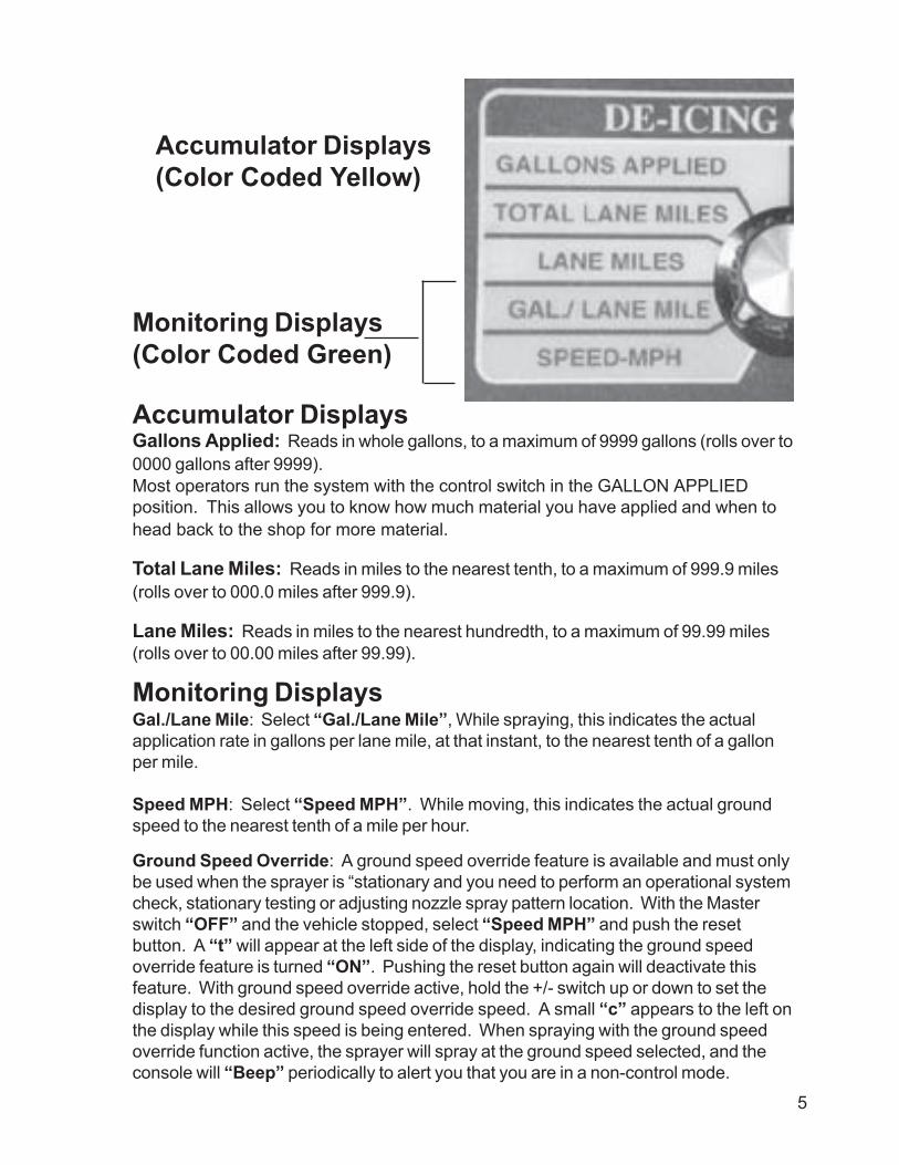
Gallons Applied: Reads in whole gallons, to a maximum of 9999 gallons (rolls over to0000 gallons after 9999).Most operators run the system with the control switch in the GALLON APPLIEDposition. This allows you to know how much material you have applied and when tohead back to the shop for more material.
Total Lane Miles: Reads in miles to the nearest tenth, to a maximum of 999.9 miles(rolls over to 000.0 miles after 999.9).
Lane Miles: Reads in miles to the nearest hundredth, to a maximum of 99.99 miles(rolls over to 00.00 miles after 99.99).
Gal./Lane Mile: Select “Gal./Lane Mile”, While spraying, this indicates the actualapplication rate in gallons per lane mile, at that instant, to the nearest tenth of a gallonper mile.
Speed MPH: Select “Speed MPH”. While moving, this indicates the actual groundspeed to the nearest tenth of a mile per hour.
Accumulator Displays(Color Coded Yellow)
Monitoring Displays(Color Coded Green)
Monitoring Displays
Accumulator Displays
Ground Speed Override: A ground speed override feature is available and must onlybe used when the sprayer is “stationary and you need to perform an operational systemcheck, stationary testing or adjusting nozzle spray pattern location. With the Masterswitch “OFF” and the vehicle stopped, select “Speed MPH” and push the resetbutton. A “t” will appear at the left side of the display, indicating the ground speedoverride feature is turned “ON”. Pushing the reset button again will deactivate thisfeature. With ground speed override active, hold the +/- switch up or down to set thedisplay to the desired ground speed override speed. A small “c” appears to the left onthe display while this speed is being entered. When spraying with the ground speedoverride function active, the sprayer will spray at the ground speed selected, and theconsole will “Beep” periodically to alert you that you are in a non-control mode.
5

.
Flow Meter Cal: Be sure the Master switch is “OFF”. Select Flow meter Cal.” Usethe +/- switch to set the flow meter calibration number to “160” for 1 1/2” flow meter and“630” for 1” flow meter.
Lane Constant: Be sure the Master switch is “ON”. Select “Lane Constant” withrotary switch. When the lane(s) switch(s) are “ON”, the display shows the accumulatedlane constants. Select each “ON” by itself, and set the desire lane constant, using the+/- switch. The constant for each lane is 99. Do Not Use Any Other Number!
Manual Override: Select “Manual Override”, wait three seconds for the function tobecome active: Now the valve will respond only to manually directed open (+) andclose (-) commands using the +/- switch. The display reads gallons per lane mileactually being applied when you are spraying (based on actual ground speed, spraywidth, and flow meter counts). This manual override function can only be activatedwhen the Master switch is “ON”. Set this to “0” value.
Rate – Gal./Lane Mile: Two different application rates can be programmed into theconsole. The operator can then switch between the two rates by depressing the“Reset” button. To enter the desired rates, turn the Master switch “OFF”. Select Rate-Gal./Lane Mile, and use the +/- switch to select the first application rate to the nearesttenth. Depress the “Reset” button to select the second rate display. Repeat theprevious step to enter the second rate. To switch between the two rates (on the go) theoperator need only switch to the Rate-Gal./Lane Mile position and depress the“Reset” switch. Switching back to the Gal./Lane Mile position allows monitoring of thecurrent rate.
Distance Cal: It is very important that you perform a calibration test for the groundspeed sensor. See page 7. This de-icing system uses a speedometer sensor unit forground speed input to the cab console.
Calibration and Setup(Color Coded Blue)
6

Performing the distance calibrationBefore the console computer is speed and distance calibrated, it might think, “100turns of the drive shaft is a mile”. We are going to tell the computer...No...this manyturns of the drive shaft is a mile. Then we enter the calibration number that we willdevelop by the following steps.
On a straight, level, low traffic road, measure a know distance of at least 400 feet.Mark a starting and end point.The farther the distance used to calibrate, the more accurate the console will be.You can use a known distance of 500, 600 and so on, as long as you enter theactual distance driven in the calibrations procedures shown below.
The console will need a temporary starting calibration number to have a general ideaof the range it will be working in.
Perform the following steps:With the console Power and the Master switch “OFF”.Select Distance Cal. With the rotary switch.Hold the reset button in while powering “ON” the console (hold the reset buttonin until the numbers on the display stop changing).When the reset button is released, the number displayed is the current distancecalibration number. This number can be changed using the +/- switch.If there is already calibration number in the console, proceed with calibration test.If there is no calibration number in the console, enter (using the +/- switch) astarting calibration number of 250. This is an arbitrary number, used only to letthe computer know the range that it should be working in.
Calibrating the consoleTurn the control console power switch “OFF” and hold the power switch down for aminimum of 3 seconds. Now turn the rotary function switch to “Speed-mph”. Turnthe Master switch to “OFF”. Turn “ON” console Power. Select “Dist. Cal.”, andhold reset button in to zero the display. Continue to hold the reset button in until thedisplay flashes “0” (about 3 seconds). Do not release the reset button untilanother 3 seconds have passed. This established the distance calibration mode.
Now drive at a slow speed of 2 – 5 mph along the measured distance. When thevehicle passes the mark at the start of the measured distance, turn “ON” the Masterswitch. The display will show the distance flashing as it accrues in feet. As the ve-hicle passes the mark at the end of the measured distance, turn “OFF” the Masterswitch. The display will show the distance that the console computer thinks thevehicle went. This distance reading may be higher or lower than the measured dis-tance. Use the +/- switch to set the display to the measured distance actually tra-versed. Once this is completed the console computer knows that this many turns ofthe driveshaft equals this much distance. Turn the control console power switch“OFF” and hold the power switch down for 3 seconds. Now turn the rotary switch toany other function and then turn the console power “ON”. Calibration is complete andwill not change unless the process is repeated. Turn the Power and the Master
7

switch “OFF”. Select Distance Cal. With the rotary switch. Hold the reset button inwhile powering “ON” the console (hold the reset button in until the numbers on thedisplay stop changing). When the reset button is released, the number displayed isnew distance calibration number. Write the new calibration number here for futurereference.____________. .
8
The control console is factory pre-set to a particular internal configuration. It is possibleto accidentally program the console to a “non-standard” mode. When this happens, theunit will not operate properly even though correct constants have been installed previ-ously or your console will not accept the entry of constants asked for in Calibration andSet-up. To return the console to standard mode do the following.
6.1.1. Standard Mode Set-up
A. Turn Console power switch “OFF”B. Turn the master switch and all lane sections switches “OFF”C. Rotate the dial to “Gallons Applied”.D. Hold down the (-) toggle switch and keep this switch down as you
also turn on the console power switch. Do Not release the (-)switch until the word “stand” appears in the console window.
You have now placed the console in the “Standard” mode.
6.1.2. Hold/Close Mode Set-Up
A. Turn the master switch and all lane section switches “OFF”.B. Turn console power switch “ON”.C. Rotate the dial to “Lane Constant”.D. Hold the “+” switch “up” and continue to hold the switch “up”
until the word “close” appears in the console window. This mayrequire 5 – 10 seconds. When the word “close” appears, releasethe (+) switch.
9
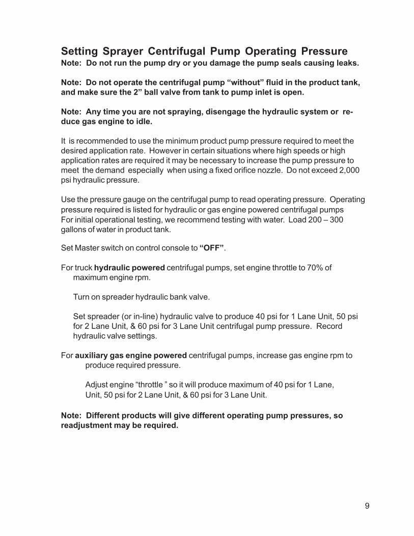
Setting Sprayer Centrifugal Pump Operating PressureNote: Do not run the pump dry or you damage the pump seals causing leaks.
Note: Do not operate the centrifugal pump “without” fluid in the product tank,and make sure the 2” ball valve from tank to pump inlet is open.
Note: Any time you are not spraying, disengage the hydraulic system or re-duce gas engine to idle.
It is recommended to use the minimum product pump pressure required to meet thedesired application rate. However in certain situations where high speeds or highapplication rates are required it may be necessary to increase the pump pressure tomeet the demand especially when using a fixed orifice nozzle. Do not exceed 2,000psi hydraulic pressure.
Use the pressure gauge on the centrifugal pump to read operating pressure. Operatingpressure required is listed for hydraulic or gas engine powered centrifugal pumpsFor initial operational testing, we recommend testing with water. Load 200 – 300gallons of water in product tank.
Set Master switch on control console to “OFF”.
For truck hydraulic powered centrifugal pumps, set engine throttle to 70% ofmaximum engine rpm.
Turn on spreader hydraulic bank valve.
Set spreader (or in-line) hydraulic valve to produce 40 psi for 1 Lane Unit, 50 psifor 2 Lane Unit, & 60 psi for 3 Lane Unit centrifugal pump pressure. Recordhydraulic valve settings.
For auxiliary gas engine powered centrifugal pumps, increase gas engine rpm toproduce required pressure.
Adjust engine “throttle ” so it will produce maximum of 40 psi for 1 Lane,Unit, 50 psi for 2 Lane Unit, & 60 psi for 3 Lane Unit.
Note: Different products will give different operating pump pressures, soreadjustment may be required.
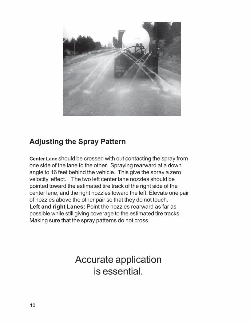
Adjusting the Spray Pattern
Center Lane should be crossed with out contacting the spray fromone side of the lane to the other. Spraying rearward at a downangle to 16 feet behind the vehicle. This give the spray a zerovelocity effect. The two left center lane nozzles should bepointed toward the estimated tire track of the right side of thecenter lane, and the right nozzles toward the left. Elevate one pairof nozzles above the other pair so that they do not touch.Left and right Lanes: Point the nozzles rearward as far aspossible while still giving coverage to the estimated tire tracks.Making sure that the spray patterns do not cross.
Accurate applicationis essential.
10

4" Strap
4" Strap
4" Strap
4" Strap
1" Square Tube
16.0
'
11
Daily Maintenance
It is mandatory to perform the following checks and make adjustments asnecessary for the items listed below. Failure to comply could result in the lossof warranty consideration and the potential danger resulting in personal injuryor loss of life if these items are not checked and adjusted as listed below.These checks must be made before leaving the shop and starting de-icingoperations.
Daily
1 Check all tank-mounting devices for tightness of tank to skid. Tightentank band nuts and re-align tank to skid if necessary.
2 Check all tightening devices holding from end of tank to truck body fortightness. Be sure to examine clevis bolts for tightness, weak and/orbent chain links, and loose turnbuckles. If turnbuckles are used andloose, be sure to tighten turnbuckle locknuts after tightening the turn-buckle.
3 Check to be sure the “tailgate clamp hooks” are in the closed positionand that skid round steel bars, located at the rear of the skid, areclamped “inside” of the tailgate hooks.
4 Check the filter screens inside the filters for cleanliness. Wash out anyclogged impurities, check “0” ring rubber gasket seal, and hand tightenonly enough to prevent leakage. Do not use a wrench to tighten filter car-tridge!
5 Check all hydraulic fittings for leakage. Re-tighten as necessary toprevent leaks.
6 Check all of the calibration and rate constants in the control console.Re-input correct rates or perform the calibration procedures as required.
7 Note: All “quick disconnect” knurled nuts must be hand tightenedonly. Tightening with a wrench will damage disconnect.
8 Check hydraulic quick disconnects for cleanliness before connecting.
12
Setup & Operation
The console is easy to use. The rotary dial selects the information displayed in thewindow. A power switch turns the console off and on. Holding the reset button in willreset the accumulator displays to zero (color coded for convenience). The +/- switchis used to change the numbers in the calibration and setup displays (also colorcoded). Individual lane switches and a console master switch are located along thebottom of the console.
Before using the system, check all of the calibration and rate constants in the controlconsole. Re-input correct rates or perform the calibration procedures as required.
Most operators run the system with the control switch in the GALLON APPLIEDposition. This allows you to know how much material you have applied and when tohead back to the shop for more material.The master switch controls all the lane switches. You can control individual lanecoverage with the Left, Center, or Right lane switches.The Sure Lane Series lets you spray, at any rate, from 20 to 60 gal./lane mile.You can slow down or speed up with the flow of traffic, while accurately applying theproduct.When you stop-and-start the vehicle at intersections, the system will automatically stop-or-start spraying at the preset rate.
Increase or decrease the application rate by pressing the reset button. It willautomatically apply the chemical at your preset rate.
Changing The Application Rate On-The-Go: There are two different ways thatthe operator can vary the application rate while the sprayer is operating:
With the “Display Selector” in the Rate – Gal./Lane Mile position, the operator canswitch between the two pre-programmed rates by depressing the “Reset” button.
Note: After changing your rate, turn the “Display Selector” dial to the Gal./LaneMile position. This allows you to view and confirm the actual new rate you willnow be spraying.
ORWith the “Display Selector” in the Gal./Lane Mile position. This allows the operatorto change the application rate, in 10% increments, while spraying, using the INC/DECswitch.
Pre-programing application rates:Power on and the master switch off with the display selector in the Gal/lane mileposition, inc/dec switch up or down to desired rate. To set an alternate rate depressthe reset button and inc/dec up or down to the desired alternate rate.
13

Alarms
1. “too Fast” When this message appears on the display, and the consolebeeps, it is an indication that the Servo control valve is fully open and isno longer responding to an open command from the control console.Slowing down will usually clear this error message, or shift to a lowergear to supply more hydraulic pump flows.
2. “no Flo”: When this message appears on the display, and the consolebeeps, it is an indication that there are no signals being received fromthe flow meter. This may be a result of lane ON/OFF valves not re-
Note: The use of this control system does not release the owner and/oroperator from product label rates and guidelines.
Mobile Spray Systems, assumes no liability for damages caused by the mis-use of this equipment and/or failure to follow labeled rates and proceduresproperly.
Mobile Spray Systems, recommends that the aaplication rates and cleanupprocedures be followed as specified by the chemical manufacturer on the label ofthe product being used.
The clean out procedure on the product label should be used to clean out theproduct tanks, pumps, and lines out through the nozzles.
Operational Notes:Ground speed override must be de-activated by pressing the “reset” button beforethe console rotary switch is rotated to any other function (position) and before theoperator performs any road spraying operations.
Before starting you actual spraying operation, you must “zero” out the gallonsapplied total in your console. Hold “reset” button in for “3” or more seconds
When doing on-the-road spraying, set your rotary dial to gallons applied andstop spraying when the gallons applied total is within 50 – 100 gallons of thetotal gallons of actual liquid you started with in the tank, so that the systempump does not run dry.
14

sponding or a faulty flow meter.
3. “Flo Hi”: When this message appears on the display, and the consolebeeps, it is an indication that the system is over-applying by 15% orgreater, and the flow Servo control valve is not responding to a closesignal from the console. This may be the result of a stuck Servo controlvalve, a power loss to the Servo control valve, a faulty motor on theServo control valve or a fault in the wiring harness.
4. “Lo bATT”: Whenever the vehicle electrical system voltage drops toolow, the Mobile Spray Systems console will display an alarm. Theconsole will beep and display the message “Lo”, “bATT” every sixseconds. Look for loose or corroded battery connections, a faultyvehicle battery or problems with the Vehicle alternator.
5. “ErrE”, “ErrC”, or “ErrR”: When any of these messages appear,contact Mobile Spray Systems directly. These could indicate an internalproblem with the console computer.
1.0 System Drain ProcedureYou must completely drain your system, using the procedure described below, anytime you have used or tested the system using water.
Note: It is only necessary to do this if you expect freezing temperaturesbefore you refill your sprayer with anti-icing/de-icing liquid.
Failure to properly drain the sprayer could result in valve and other damage!
15
Nozzle Skid Procedure
1 Disconnect all hose quick disconnect fittings from the lane nozzleassemblies. These are located on the back side of each assembly.
2 Disconnect the cap quick disconnect from the end of the 2” manifoldtee. The valve(s) are located on the right side of the nozzle skid.
3 Remove the 2” pressure filter cover and screen. This filter is at-tached on the left side of the Servo valve.Note: Clean screen if necessary.
4 Open the pet cock on the bottom of the centrifugal pump.

5 Remove the 2” Y-strainer cover and screen on the tank/fill drain line.Note: Clean screen if necessary.
6 Remove the lever action drain cap located on end of tank fill/drainline.
7 Open both 2” ball valves. (Pump suction line and tank fill/drain line.)
Control Console Procedure
1 Turn console power “ON”.
2 Install a simulated ground speed of 10 mph in the console.
3 Turn on all applicable lane switches.
4 Turn on “Master” switch.
5 Leave all switches on until system stops draining from all of the areasmentioned in procedure A1-A7.
When you are satisfied all draining has stopped, turn off the“Master” switch and wait again for system to stop draining.
6 Repeat steps 4 & 5 two more times. It is necessary to do this toinsure all water has drained out of the flow meter, and the water thatis normally trapped between the electric ball valves and the valvecovers.
7 Turn “OFF” console power and reinstall all filter screens, filter cov-ers, and re-connect all hose quick disconnects.
16

Leave sufficient length at the cab connector so that it will reach the mating connectorfrom the cab harness. When the cab connector is disconnected, both ends must havethe dust cover installed to protect the contacts.
Be sure the white “O” ring seal is in place inside the main cable disconnects where it isconnected. This is important in order to protect the contacts from corrosion.
FAILURE TO FOLLOW THESE INSTRUCTIONS MAY DAMAGETHE SYSTEM AND VOID THE WARRANTY.
CONNECT ALL POWER LEADS DIRECTLY TO THE VEHICLEBATTERY!
ElectricalThe main sprayer harness must be connected, as shown on the diagram,directly to the vehicle battery. Route the cabling so that it is secured andprotected from physical damage. Be sure the implement status jumper plugis installed (if equipped.)
InstallationHydraulics.
Two hydraulic lines are needed to supply the appropriate amount offlow to the hydraulic Motor. Utilize both hydraulic outlets from the vehiclehydraulic system. Tee the two lines off to one line connected to thesingle inlet on the hydraulic motor. Only one return line to the vehiclehydraulic system is necessary. Use the both spreader and sander con-trols to adjust to the pressures shown below.
17
DO NOT SUBSTITUTE HIGHER AMPERAGE FUSESTHIS SYSTEM HAS BEEN DESIGNED TO GIVE OPTIMUM PERFORMANCEWHEN CONNECTED AS SHOWN. POWER CONNECTIONS OTHER THANDIRECTLY TO THE VEHICLE BATTERY AND/OR THE USAGE OF HIGHER
AMPERAGE FUSES MAY DAMAGE THE SYSTEM AND VOID THE WARRANTY.

Mak
e th
is co
nnec
tion
insid
e th
e ca
b.
18

Vehicle Battery
a b c d
a b c d a b c d a b c d
a b c da b c da b c da b c d
a b c
Control ConsoleMT75-03009 Cable driven speed
sensor (Mechanical)E0078
Ground Speed Sensor (Electronic)AA 1800-03 D Or Pulsar PS3
+ -
Flowmeter InterfaceMT78-05003
20 AMP FUSE
Flowmeter1 1/2" P0486 or1" P0486A
Lane Shut Off ValvesP0562
Regulating ValveP0573
De-Icer InterfaceHarness - Flowmeter
MT45-10037
19

20
To Sensor
To Servo Valve
To Lane Valves
a b c d a b c d a b c d a b c d
Blue Ground
Brown +12 vBlack Signal
no connectionWhite 12 v to close Green 12 v to open
no connection
To Console Harness
Rear Harness
a b c
20

21
Most vehicles built since the early nineties are quipped with a factory installed speedsensor, The speed sensor is commonly referred to as the VSS. Most VSS units arelocated on the transmission of the vehicle and the speedometer signal wire is pluggeddirectly into it.
The Sensor has come equipped with a four pin AMP connector and one single yellowlead.
Connect the Amp connector to the speed input line of the console.
Connect the yellow wire to the vehicle speed sensor VSS. The VSS generally hastwo wires. Check operation by driving on the road, and read ground speed onthe cab control console. If unit does not operate properly, reverse lead and re-test.
The DIVIDER pin block has 6 different pin positions Always keep the jumper in thefar left position. This jumper setting will give your sprays system the quickest responsetime and the most accurate application.
Sensitivity is controlled by the three pin block. The center jumper setting is mostsensitive, the right pin is less sensitive.
The sensitivity pin jumper has been factory set to the far right position.
If you are not receiving pulse signals at low speeds, move the sensitivity jumper pin leftto the center position.
Divider Jumper Block
Sensitivity Jumper Block
E0077A Speed Sensor

For Chassis Manufactured Prior to September 1997
Speedometer and Tachometer Outputs
Interfaces conforming to TMC RP 123 are provided for Speedometer andTachometer signals. Speedometer output is calibrated to 30,000 pulses per mile.Tachometer output is 12 pulses per engine revolution. Access to these signals istypically provided by two Deutsch DT series connectors. Aftermarket access isprovided through connector 436. Connector 436 is a 6-way Deutsch DT seriesconnector located behind the vehicle dash. Connector 435 is a 12-way Deutsch DTseries connector collocated with connector 436. The VPM signal sources, connec-tors and circuits are shown in the table below.
Cavity 5 of connector 436 provides speedometer pulses and cavity 6 of con-nector 436 provides tachometer pulses. VPM pins 20 (connector 436, cavity 1) and5 (connector 435, cavity 11) are used for the instrument cluster. Use terminal partnumber 1680206C1 insert circuits into connector 436. Use 16 or 18 gauge wire withGXL insulation. Remove the cavity plug and connector lock and insert the terminalinto the connector cavity. Then replace the connector lock. Use terminal2005483C1 to insert circuits into the VPM connector. Insert circuits into the VPM,only when the VPM is directly wired into the main harness.
The sink and source currents for the available interfaces are shown below.All the interfaces source 5 milliamps. Two enhanced interfaces are provided thatsink 5 milliamps, instead of 50 micro amps. These interfaces are noted in the tablebelow. The signal waveform provided is the same both the standard and enhancedinterfaces. See TMC RP 123 for more information about the signal waveform.
Speedometer Signal Locations
Speedometer Interfaces VPM Connector, Pin Cavity, Circuit Signal 18 47B Speedo1
19 N.C. Speedo 20 436, 1, 47C Speedo
Signal Interface Parameters
Paramter Potential Paramter CurrentVo low 0 to 0.5 volts I sink (Vo low)1 50 micro ampsVo high 4 V to V battery I source (Vo high) 5 milliamps
1Designates enhanced interfaces that sink 5 milliamps of current instead of 50 micro amps
22

4.2 Speedometer Signal (Wire 157)This signal provides a zero to (V bat –2) volt pulse signal from the ECU todrive an electronic speedometer.This signal conforms to a 50% dutycycle square wave as defined on theControls Specifications installation drawing. The number of pulses peroutput shaft revolution may vary bymodel. Refer to the Controls Specifi-cation Drawing AS07-001 for detaildefinition.
The Speedometer signal is availablefrom two sources; on output Wire 357from the VIM, and on output Wire157 through the VIW-S wiring con-nector.
Allison TransmissionWorld Transmission –WTEC III Controls
Either of these signals may be used forany vehicle system, which requires aspeed signal. This signal may be useddirectly by the speedometer (or otherdevice) or, if a signal type other than anon-zero-crossing is needed, it may beused as input to a signal converter.Signal converters are used to convertthe ECU output signal into either zero-crossing or non-zero-crossing format.
— Wire 157 (as VTW #2 output)Vehicle Interface Wiring
— Wire 157 (as VIM output) Vehicle Interface Module
23

OEM Model
Electronic Control Unit
DDR Connector
Diagnostic Data Reader
VIM Vehicle Interface Model
VIW Vehicle Interface Wiring
Harness Vendor
OEM Phone Number
Crane Carrier 918-836-1651
Ford Louisville
Under cab access plate in floor
Under dash @ LF door pillar
Under cab with ECU
Under cab with ECU & VIM
Freightliner American LaFrance FL60/70/80/100 FLD120/112
Under cab above right side headlight In design In design
In cab, driver side below right knee
Consult OEM
Consult OEM
Packard in Mexico
800-FTL-HELP 800-385-4357
GMC/Chevrolet Topkick/Kodiak
Inside left frame rail behind front wheel
Beneath steering wheel column
Next to ECU inside left frame rail
Inside engine compartment
Packard
800-875-4742
Kenworth TBD KME 717-669-
9461 Mack LE MR RD
Under left drivers seal Under PB shift selector Under right center dash panel
Left driver side lower dash Left driver side lower dash Left driver side lower dash
ATD VIM not used Top rear engine tunnel cover Under right center dash panel
Under left drivers seal Top rear engine funnel cover Under top center dash panel
AFL & some St. Clari
610-709-2483
Navistar Most truck models
Back of cab interior
Under dash on driver’s side
Not Used
Back of Cab I anterior
Alphabet
800-448-7825
Peterbuilt 320 330 357 other conventionals
Behind driver’s seat Center of dash under access cover TBD
Center of dash under access cover Left of steering column
Behind driver’s seat next to ECU ATD VIM not used Steering column support brace ATD VIM not used
Imput/output functions: PTO/Auto N behind driver’s seat Others under steering column Engine Compartment firewall on driver’s side.
AFL AFL
Volvo WX WXR WXLL (stand up) WXLL (sit down)/WX95 WG
Under drivers seat Front firewall cab side Under drivers seat Under drivers seat Shift tower
Engine tunnel right hand side Engine tunnel right hand side RH Side of drivers sest Engine tunnel left hand side Back side of shifter housing
ATD VIM not used ATD VIM not used ATD VIM not used ATD VIM not used ATD VIM not used
All models Chassis wiring uses St. Clair Cab wiring uses Alphabet
910-393-3292 or 910-393-4731
24

25

Mobile Spray Systems Parts Listings
Anti/De-Icing Electronic Control System Parts
Part Number DescriptionMT75-03009 Spratronics control consoleMT45-10037 Control system wiring harnessMT78-05003 Flowmeter interface cableMT401-0016 System power cableE0077 Vehicle Speed Sensor, electronicE0078 Vehicle Speed Sensor, mechanicalP0486 1 1/2” Flowmeter w/ barbsP0562 1” lane shut-off valve(s) manifold styleP0508 2” regulating valve manifold style
Anti/De-Icing System Plumbing PartsPart Number DescriptionP0495 Centrifugal pump w/ hydraulic motorP0265 1/8” Drain PetcockP0511 Pressure gauge 0-160 psi (bottom stem)P0397 2” Ball valveP0591 2” T-strainer 20 mesh manifold styleP0614 2” manifold teeP0612 2” manifold 90°P0613 2” manifold X 1 1/2” hb 90°P0611 2” manifold capP0616 1” manifold teeP0615 1” manifold 90°P0617 1” manifold X 1 1/4” hb 90°P0618 1” manifold X 1 1/4” hbP0470 2” Y-strainer, 80 meshP0514 2” x 2” Hose Saver disconnect 90°P0437 2” x 2” Hose Saver disconnectP0262 2” valve w/ male camlock disconnectP0282 1” street ell 90°P0149 1 1/4’ street ell 90°P0279 1” x 3/4” reducing nippleP0611 1 1/4” X 1” reducing bushingP0147 1 1/4” X 4” poly nippleP0027 1 1/4” poly teeP0223 1 1/4” x 1 1/4” 90° Hose Saver disconnectS0026 Variable Orifice Nozzle
26
Mobile Spray SystemsEquipment Warranty
WarrantyGreen Pros West dba MOBILE SPRAY SYSTEMS., (herein called Seller) warrants to theoriginal purchaser that, if any part of the Mobile Spray Systems equipment proved to bedefective in material or workmanship, upon inspection and examination by Seller, within oneyear of the date of manufacture, and is returned to Seller, transportation prepaid, within thirtydays after such defect is discovered, Seller will (at its option) either replace or repair saidproduct, except that the warranty for expendable parts such as light bulbs and batteries islimited to thirty (30) days. The MOBILE SPRAY SYSTEMS equipment will not be considereddefective if it substantially fulfills the performance specifications. Purchaser shall be respon-sible for all maintenance services, if any, all in accordance with procedures outlined in Seller’smaintenance literature.
Extended WarrantyMOBILE SPRAY SYSTEMS provides one year minimum parts and factory warranty on allMOBILE SPRAY SYSTEMS sprayers. Any components with a longer manufacturer’s warrantywill be honored. Warranty identification documents will be provided at the time of delivery.(Warranty provided for Mobile Spray Systems computer console is 2-1/2 years.)
Warranty Limitation and ExclusionSeller will have no further warranty obligation hereunder if the Mobile Spray Systems equip-ment is subjected to abuse, misuse, improper or abnormal usage, faulty installation, impropermaintenance as provided in Seller’s maintenance literature, or any repairs other than thoseprovided by the Seller and/or its authorized representatives or if damages or failure is causedby or attributable to acts of God. Seller neither assumes nor authorizes anyone to assume forit any other obligation or liability in connection with the MOBILE SPRAY SYSTEMS equipment.
Disclaimer of Unstated WarrantiesThe warranty printed above is the only warranty applicable to this purchase. All other warran-ties expressed or implied including, but not limited to, the implied warranties of merchantabilityand fitness for a particular purpose are disclaimed.
Customer Service PolicyMOBILE SPRAY SYSTEMS., customer service policy is to ship all replacement componentswithin 48 regular scheduled working hours by standard delivery.
Limitation of LiabilityIt is understood and agreed that seller’s liability, whether in contract, in tort, under any war-ranty, in negligence or otherwise, shall not exceed the return of the amount of the purchaseprice paid by purchaser and under no circumstances shall seller be liable for special, indirect,or consequential damages. The price stated for the Mobile Spray Systems equipment is aconsideration in limiting seller’s liability. No action, regardless of form, arising out of thetransactions under this agreement may be brought by purchaser more than one year afterthe cause of action has occurred.
Purchaser accepts these terms and warranty limitation unless MOBILE SPRAY SYSTEMSequipment is returned within fifteen (15) days for full refund of purchase price.
27