Embed Size (px)
Citation preview
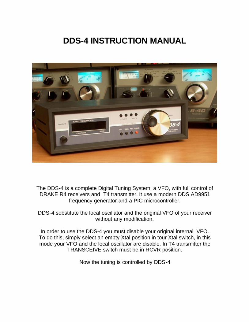
DDS-4 INSTRUCTION MANUAL
The DDS-4 is a complete Digital Tuning System, a VFO, with full control of DRAKE R4 receivers and T4 transmitter. It use a modern DDS AD9951
frequency generator and a PIC microcontroller.
DDS-4 sobstitute the local oscillator and the original VFO of your receiver without any modification.
In order to use the DDS-4 you must disable your original internal VFO.
To do this, simply select an empty Xtal position in tour Xtal switch, in this mode your VFO and the local oscillator are disable. In T4 transmitter the
TRANSCEIVE switch must be in RCVR position.
Now the tuning is controlled by DDS-4
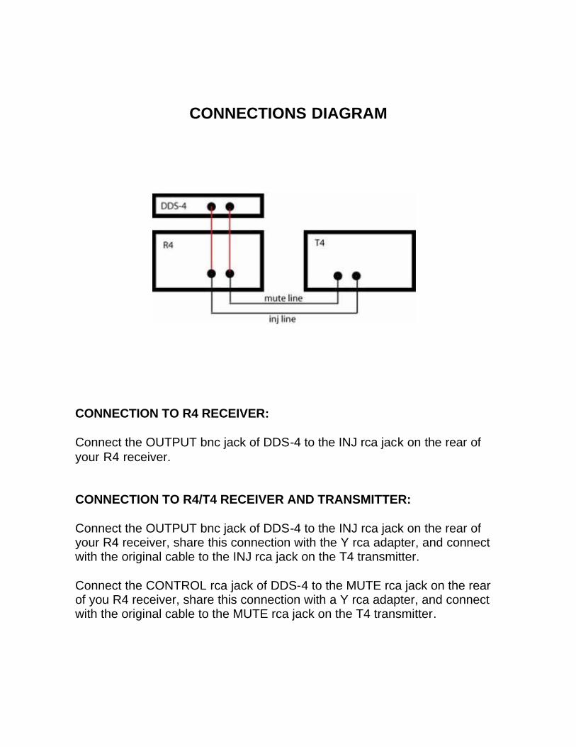
CONNECTIONS DIAGRAM
CONNECTION TO R4 RECEIVER: Connect the OUTPUT bnc jack of DDS-4 to the INJ rca jack on the rear of your R4 receiver. CONNECTION TO R4/T4 RECEIVER AND TRANSMITTER: Connect the OUTPUT bnc jack of DDS-4 to the INJ rca jack on the rear of your R4 receiver, share this connection with the Y rca adapter, and connect with the original cable to the INJ rca jack on the T4 transmitter. Connect the CONTROL rca jack of DDS-4 to the MUTE rca jack on the rear of you R4 receiver, share this connection with a Y rca adapter, and connect with the original cable to the MUTE rca jack on the T4 transmitter.
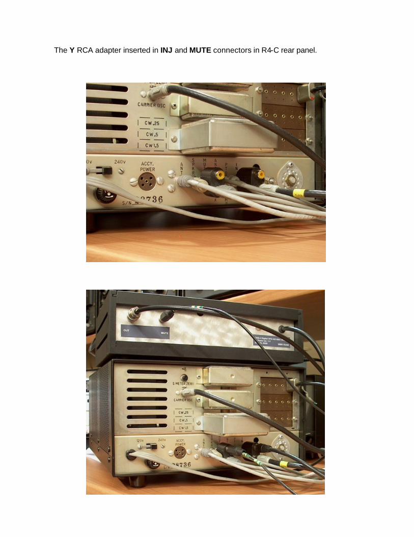
The Y RCA adapter inserted in INJ and MUTE connectors in R4-C rear panel.
DISPLAY & FUNCTIONS
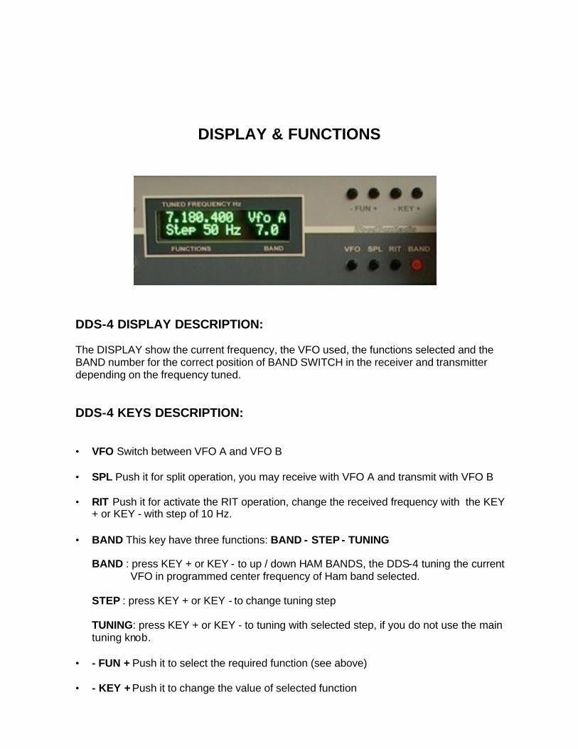
DDS-4 DISPLAY DESCRIPTION: The DISPLAY show the current frequency, the VFO used, the functions selected and the BAND number for the correct position of BAND SWITCH in the receiver and transmitter depending on the frequency tuned. DDS-4 KEYS DESCRIPTION: • VFO Switch between VFO A and VFO B • SPL Push it for split operation, you may receive with VFO A and transmit with VFO B • RIT Push it for activate the RIT operation, change the received frequency with the KEY
+ or KEY - with step of 10 Hz.
• BAND This key have three functions: BAND - STEP - TUNING
BAND : press KEY + or KEY - to up / down HAM BANDS, the DDS-4 tuning the current VFO in programmed center frequency of Ham band selected. STEP : press KEY + or KEY - to change tuning step TUNING: press KEY + or KEY - to tuning with selected step, if you do not use the main tuning knob.
• - FUN + Push it to select the required function (see above) • - KEY + Push it to change the value of selected function

DDS-4 FUNCTION DESCRIPTION: • LOCK Lock the main tuning knob. The tuning is avaible only with the keys. Pushing KEY+ set the fun. ON / OFF. • TX TIME When press PTT the display show the a time passing during trasmission. Pushing KEY+ set the fun. ON / OFF. • MEM WRITE: The current frequency tuned (VFOa or VFOB) is stored in select
memory position. To select the position press KEY + KEY - to scroll the 20 memories. To write the memory press BAND red key. • MEM READ: Recall a frequency from memory. Press KEY + KEY - to scroll the 20 memories. If a memory is empty, the receiver is muted. • SCAN A --> B: The scan run from VFO A to VFO B direction. Tune VFO A to start frequency Tune VFO B to stop frequency Push BAND key, a STORE message is displayed to confirm the SCAN
is ready. Push KEY+ to START and STOP scanning, when stopped you can
tune manually the VFO to desidered station, if you push KEY + again the scan restart from actual frequency.
• SCAN MEM: The scan run on memories. Push KEY+ to START and STOP scanning. • VFO A = B: Copy the frequency of VFO B to VFO A • VFO B = A: Copy the frequency of VFO A to VFO B • SWL BAND: press KEY + or KEY - to up / down SWL BANDS, the DDS-4 tuning the
current VFO in programmed center frequency of Ham band selected. • DDS level : press KEY + or KEY - to adjust the DDS level output.
the output DDS level can be programmed from +8 dBm ( 16385 on the display to – inf. ( 0 on the display) . The step level are 128 . This is necessary to setup the correct injection level on the receiver mixer or to use the VFO as generator. The selected level is stored permanently on the EEPROM.
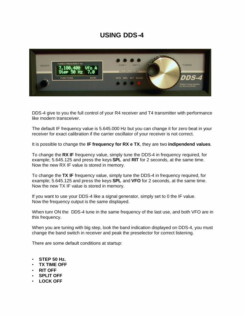
USING DDS-4
DDS-4 give to you the full control of your R4 receiver and T4 transmitter with performance like modern transceiver. The default IF frequency value is 5.645.000 Hz but you can change it for zero beat in your receiver for exact calibration if the carrier oscillator of your receiver is not correct. It is possible to change the IF frequency for RX e TX, they are two indipendend values. To change the RX IF frequency value, simply tune the DDS-4 in frequency required, for example; 5.645.125 and press the keys SPL and RIT for 2 seconds, at the same time. Now the new RX IF value is stored in memory. To change the TX IF frequency value, simply tune the DDS-4 in frequency required, for example; 5.645.125 and press the keys SPL and VFO for 2 seconds, at the same time. Now the new TX IF value is stored in memory. If you want to use your DDS-4 like a signal generator, simply set to 0 the IF value. Now the frequency output is the same displayed. When tunr ON the DDS-4 tune in the same frequency of the last use, and both VFO are in this frequency. When you are tuning with big step, look the band indication displayed on DDS-4, you must change the band switch in receiver and peak the preselector for correct listening. There are some default conditions at startup: • STEP 50 Hz. • TX TIME OFF • RIT OFF • SPLIT OFF • LOCK OFF
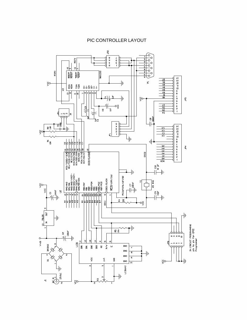
PIC CONTROLLER LAYOUT
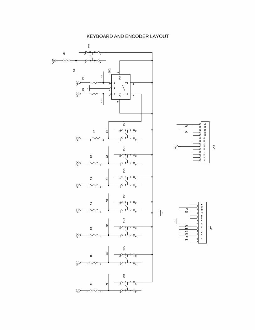
KEYBOARD AND ENCODER LAYOUT
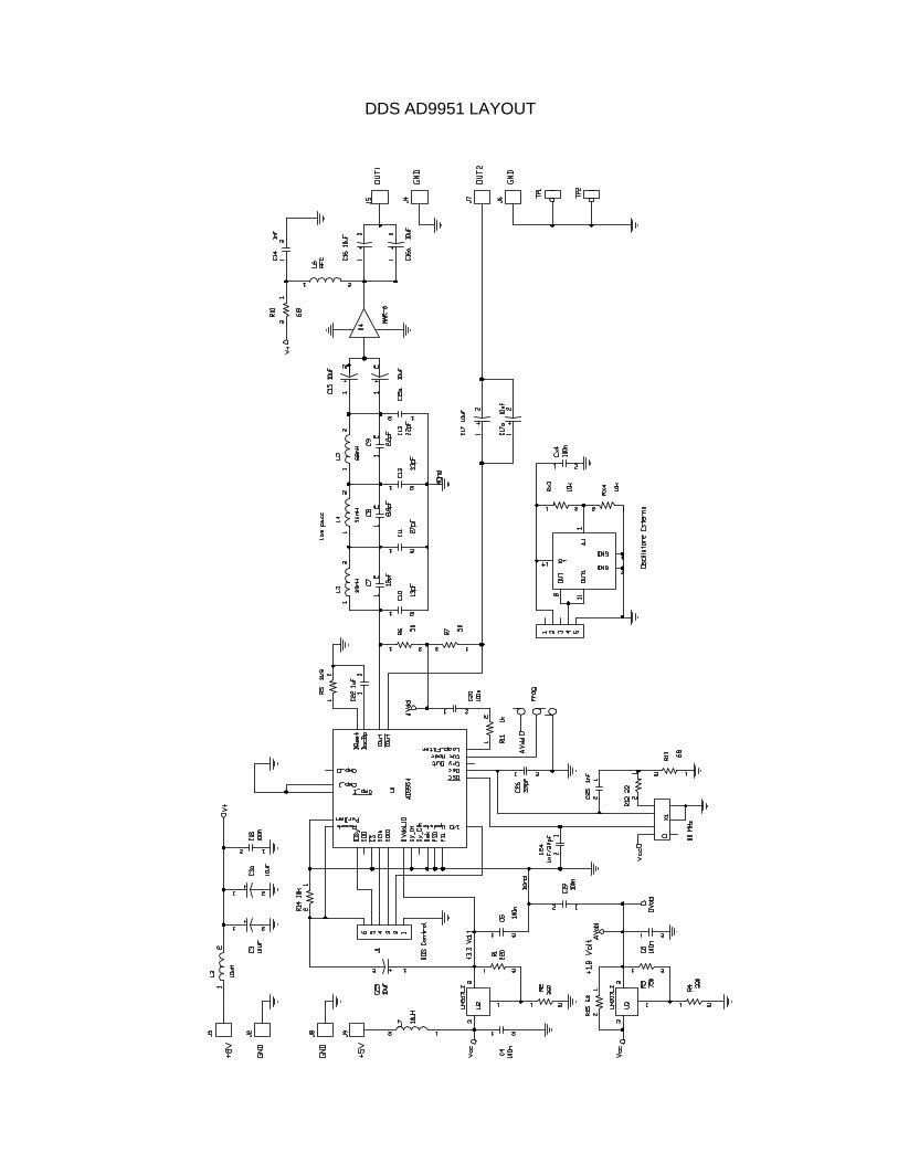
DDS AD9951 LAYOUT
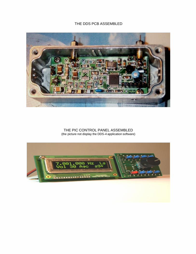
THE DDS PCB ASSEMBLED
THE PIC CONTROL PANEL ASSEMBLED (the picture not display the DDS-4 application software)
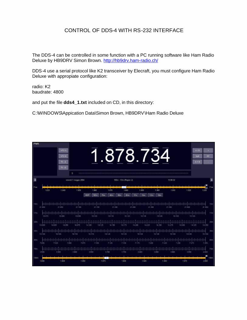
CONTROL OF DDS-4 WITH RS-232 INTERFACE
The DDS-4 can be controlled in some function with a PC running software like Ham Radio Deluxe by HB9DRV Simon Brown. http://hb9drv.ham-radio.ch/ DDS-4 use a serial protocol like K2 transceiver by Elecraft, you must configure Ham Radio Deluxe with appropiate configuration: radio: K2 baudrate: 4800 and put the file dds4_1.txt included on CD, in this directory: C:\WINDOWS\Appication Data\Simon Brown, HB9DRV\Ham Radio Deluxe
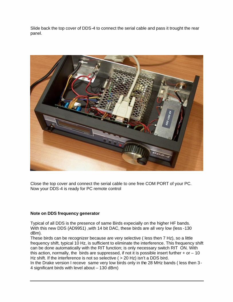
Slide back the top cover of DDS-4 to connect the serial cable and pass it trought the rear panel.
Close the top cover and connect the serial cable to one free COM PORT of your PC. Now your DDS-4 is ready for PC remote control Note on DDS frequency generator Typical of all DDS is the presence of same Birds expecially on the higher HF bands. With this new DDS (AD9951) ,with 14 bit DAC, these birds are all very low (less -130 dBm). These birds can be recognizer because are very selective ( less then 7 Hz), so a little frequency shift, typical 10 Hz, is sufficient to eliminate the interference. This frequency shift can be done automatically with the RIT function; is only necessary switch RIT ON. With this action, normally, the birds are suppressed, if not it is possible insert further + or – 10 Hz shift. If the interference is not so selective ( > 20 Hz) isn’t a DDS bird. In the Drake version I receve same very low birds only in the 28 MHz bands ( less then 3 -4 significant birds with level about – 130 dBm)
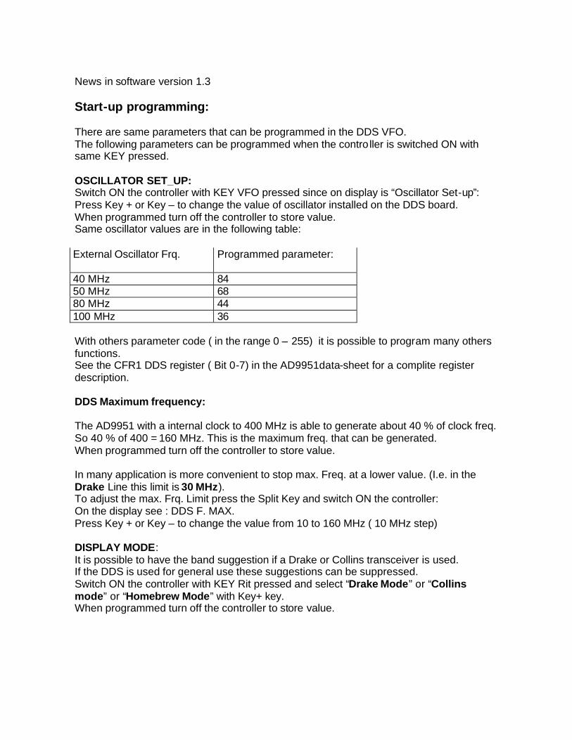
News in software version 1.3 Start-up programming: There are same parameters that can be programmed in the DDS VFO. The following parameters can be programmed when the controller is switched ON with same KEY pressed. OSCILLATOR SET_UP: Switch ON the controller with KEY VFO pressed since on display is “Oscillator Set-up”: Press Key + or Key – to change the value of oscillator installed on the DDS board. When programmed turn off the controller to store value. Same oscillator values are in the following table: External Oscillator Frq. Programmed parameter:
40 MHz 84 50 MHz 68 80 MHz 44 100 MHz 36 With others parameter code ( in the range 0 – 255) it is possible to program many others functions. See the CFR1 DDS register ( Bit 0-7) in the AD9951data-sheet for a complite register description. DDS Maximum frequency: The AD9951 with a internal clock to 400 MHz is able to generate about 40 % of clock freq. So 40 % of 400 = 160 MHz. This is the maximum freq. that can be generated. When programmed turn off the controller to store value. In many application is more convenient to stop max. Freq. at a lower value. (I.e. in the Drake Line this limit is 30 MHz). To adjust the max. Frq. Limit press the Split Key and switch ON the controller: On the display see : DDS F. MAX. Press Key + or Key – to change the value from 10 to 160 MHz ( 10 MHz step) DISPLAY MODE: It is possible to have the band suggestion if a Drake or Collins transceiver is used. If the DDS is used for general use these suggestions can be suppressed. Switch ON the controller with KEY Rit pressed and select “Drake Mode” or “Collins mode” or “Homebrew Mode” with Key+ key. When programmed turn off the controller to store value.