Embed Size (px)
Citation preview

1dc2608f
DEMO MANUAL DC2608
DESCRIPTION
DC2618 and DC2210 LTC2986-1
Digital Temperature Measurement System
The DC2608 is the starter kit for demonstrating the per-formance and ease of use of the LTC®2986-1, which is a complete temperature measurement system on a chip. This kit includes the DC2618 (main demo circuit contain-ing the LTC2986-1) and the DC2210 (a simple experiment circuit allowing bread boarding). In addition to the starter demonstration kit, sensor specific demonstration boards highlighting the performance of RTDs, thermistors, or thermocouples are also available.
• Universal Temperature Measurement Board – DC2211
• Thermocouple Board – DC2212
• Dedicated RTD Board – DC2213
• Dedicated Thermistor Board – DC2214
L, LT, LTC, LTM, Linear Technology, the Linear logo and Linduino are registered trademarks and QuikEval is trademark of Analog Devices, Inc. All other trademarks are the property of their respective owners.
The DC2618 is a member of the QuikEval™ family of dem-onstration boards. It is designed to allow easy evaluation of the LTC2986-1 and may be connected to any one of the sensor daughter boards.
These daughter boards allow evaluation of the various LTC2986-1 sensor types (see Figure 1).
For the serial digital interface, the DC2618 may be con-nected to the DC2026 Linduino® One.
Design files for this circuit board are available at http://www.linear.com/demo/DC2608
Figure 1. DC2618 Temperature Measurement Demonstration Board

2dc2608f
DEMO MANUAL DC2608
QUICK START PROCEDUREConnect one of the five sensor daughter boards (DC2210, DC2211, DC2212, DC2213 or DC2214) to the DC2618 demo board. Connect the DC2618 to a DC2026 using the supplied 14-conductor ribbon cable. Connect the DC2026 to the PC using a standard USB A/B cable. Run the QuikEval software which the latest version can be downloaded from the Linear website at www.linear.com/software. The LTC2986-1 demo program will be loaded automatically. Refer to software manual LTC2986DSM for more detailed information.
The demo software helps program and run the LTC2986-1. It can configure the LTC2986-1, check and save the con-figuration, run the LTC2986-1, output the results into a file, and even create Linduino One ready C code based on the configuration. The demo software allows the user to configure the LTC2986-1 manually or automatically from data stored in the daughter board EEPROM. Please see www.linear.com/LTC2986software for the demo software manual. It includes a short tutorial for getting started. Figure 2 shows a screenshot of the demo software at start-up.
Figure 2. LTC2986-1 Demo Software

3dc2608f
DEMO MANUAL DC2608
HARDWARE SETUPDC2210 EXPERIMENTER BOARD (INCLUDED IN DC2608 KIT)
The DC2210 experimenter board (see Figure 3) brings all LTC2986-1 channels plus the COM connection out to a proto area and a 24-position terminal block. The user may
connect any of the supported sensors and sense resistors to any of the LTC2986-1 inputs in this area. Figure 4 shows the connection schematic of the DC2210 Experimenter board. Please note that only CH1 to CH10 are valid on the DC2210 when used in conjunction with the DC2618.
Figure 3. DC2210 Experimenter Board

4dc2608f
DEMO MANUAL DC2608
HARDWARE SETUP
Figure 4. DC2210 Experimenter Board Schematic
J1
J2
J3

5dc2608f
DEMO MANUAL DC2608
HARDWARE SETUPDC2211 UNIVERSAL TEMPERATURE MEASUREMENT BOARD
The universal temperature measurement board (see Figure 5) allows the user to connect any of the LTC2986-1 supported sensors to the DC2618 demo board.
Figure 5. DC2211 Universal Temperature Measurement Board

6dc2608f
DEMO MANUAL DC2608
HARDWARE SETUPThe universal temperature measurement board has a built-in sense resistor for RTD applications as well as a cold junction sensor diode for thermocouple applications (see Figure 6 for the DC2211 schematic diagram). The sense resistor is a 2kΩ ±0.1% 10ppm/°C sense resistor on channels 1 and 2 which may be used with any of the supported RTD sensor types. The precise value of this sense resistor is stored in an on-board EEPROM. The LTC2986-1 demo software can read this EEPROM and use to configure the sense resistor value in the LTC2986-1’s configuration memory.
The external interface on the universal temperature mea-surement board is an 8-position screw-terminal block with the flowing pinout.
Table 1. DC2211 Terminal Connector PinoutPosition A LTC2986-1 CH2 as well as the low side of the on-board
2k sense resistor
Position B LTC2986-1 CH3
Position C LTC2986-1 CH4
Position D LTC2986-1 CH5
Position E Common/Ground Connection
Position F Common/Ground Connection
Position G Common/Ground Connection
Position H Common/Ground Connection
Figure 6. DC2211 Universal Temperature Measurement Board Schematic
J2
J1
R6
Q1
R5, 100Ω
R4, 100Ω
R3, 100Ω
R2, 100Ω
R1, 100Ω

7dc2608f
DEMO MANUAL DC2608
HARDWARE SETUPUNIVERSAL TEMPERATURE MEASUREMENT DAUGHTER BOARD EXAMPLES
• Four thermocouples connected to positions A-D with the negative connections tied to positions E-H using the on-board diode as cold junction sensor (see Figure 7a for the schematic and Figure 8a for the corresponding software configuration).
• A 4-wire RTD connected to positions A-D using the on-board sense resistor as the ratiometric reference (see Figure 7b for the schematic and Figure 8b for the corresponding software configuration).
Figure 7. Universal Temperature Measurement Board Examples

8dc2608f
DEMO MANUAL DC2608
HARDWARE SETUP
Figure 8a. DC2211 Four Thermocouple Software Configuration

9dc2608f
DEMO MANUAL DC2608
HARDWARE SETUP
Figure 8b. DC2211 4-Wire RTD Software Configuration

10dc2608f
DEMO MANUAL DC2608
HARDWARE SETUPDC2212 THERMOCOUPLE DAUGHTER BOARD
The thermocouple board (see Figure 9) demonstrates the flexibility, accuracy, and low noise features of the LTC2986-1 thermocouple modes.
If the user wishes to connect external sensors to the thermocouple board, two universal-type thermocouple jacks (J2 and J3) are provided (see schematic diagram Figure 10 and corresponding software configuration Figure 11). The user may connect any of the LTC2986-1 supported thermocouples (B, E, J, K, N, R, S, or T) as well as custom thermocouples through these jacks.
To demonstrate the flexibility of the LTC2986-1, the ther-mocouple board includes cold junction diodes (Q1 and Q2) embedded in each thermocouple socket. Alternatively, a 4-wire PT100 RTD (R5) can be used as the cold junction sensor for either or both thermocouples.
To demonstrate the low system noise and offset of the LTC2986-1, the thermocouple board provides a short to ground on channel 5.
To demonstrate the accuracy of the LTC2986-1, the ther-mocouple board allows the user to connect a thermocouple calibrator or an external voltage source to CH10 of the LTC2986-1 through a pair of banana jacks (J4 and J5).
Figure 9. DC2212 Thermocouple Daughter Board

11dc2608f
DEMO MANUAL DC2608
HARDWARE SETUP
Figure 10. DC2212 Thermocouple Board Schematic

12dc2608f
DEMO MANUAL DC2608
HARDWARE SETUP
Figure 11. DC2212 Software Configuration

13dc2608f
DEMO MANUAL DC2608
HARDWARE SETUPDC2213 DEDICATED RTD BOARD
The DC2213 dedicated RTD board (see Figure 12) dem-onstrates the flexibility, accuracy, and low noise features of the LTC2986-1 RTD sensor modes. The DC2213 pro-vides several circuits demonstrating the features of the LTC2986-1.
The DC2213 (see schematic diagram Figure 13 and cor-responding software configuration Figure 14) provides a 2kΩ ±0.1% 10ppm/°C sense resistor on channels 2 and 3 which may be used with any of the RTD sensor circuits on this board. An additional Kelvin connection is also provided to this sense resistor on channel 1. The precise
measured value of this sense resistor is stored in an on-board EEPROM which the LTC2986-1 demo software can read and use to configure the sense resistor value.
To demonstrate the low system noise of the LTC2986-1, the dedicated RTD board provides a 0°C PT100 simulator (100Ω ±0.01% 10ppm/°C) on channels 3 to 6 configured as a 4-wire sensor. In addition to this the user may use this circuit to demonstrate how the rotated mode eliminates measurement error introduced by parasitic thermocouples. To facilitate this measurement, the DC2213 provides an external thermocouple interface which acts as a parasitic thermocouple.
Figure 12. DC2213 Dedicated RTD Board

14dc2608f
DEMO MANUAL DC2608
HARDWARE SETUPTo see the effects of parasitic thermocouples on non-rotated measurement modes, first measure the on-board 0°C PT100 simulator in a non-rotated configuration and see the measurement error as the thermocouple’s temperature changes. To see the benefit of the rotated measurement mode, switch from the no rotation/sharing to the rotation/sharing configuration and see the errors introduced by the parasitic thermocouple minimized.
In addition to the fixed value RTD simulator, there is also a variable resistor RTD simulator. This circuit can be used to demonstrate the range of the various LTC2986-1 RTD sensor modes as well as demonstrate the fault detection
capabilities of the LTC2986-1. Please note that the variable resistor feature of the DC2213 requires channel 11 and will not work with the DC2618.
If the user wishes to connect an external RTD to the sensor board, a 4-position terminal block is provided. The user may connect any of the LTC2986-1 supported RTDs as well as custom RTDs to the DC2618 demo board through this interface. The interface may be configured for 3 or 4 wire sensors. To demonstrate the accuracy of the LTC2986-1, the user may also connect an RTD calibrator or precision resistors to this interface.
Figure 13. DC2213 Dedicated RTD Board Schematic
J2
J3
JP1
R6
THIS FEATURE WILL NOTWORK WITH THE DC2508 BECAUSE CHANNEL 11 IS NOTPRESENT ON THE DC2508

15dc2608f
DEMO MANUAL DC2608
HARDWARE SETUP
Figure 14. DC2213 Software Configuration

16dc2608f
DEMO MANUAL DC2608
HARDWARE SETUPDC2214 DEDICATED THERMISTOR BOARD
The DC2214 dedicated thermistor board includes several circuits (see Figure 15) to demonstrate the flexibility, ac-curacy, and low noise features of the LTC2986-1 thermistor sensor modes.
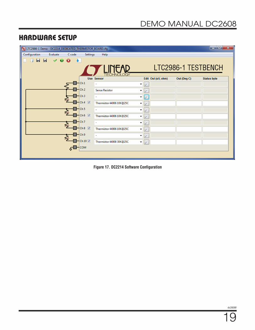
The DC2214 provides a 10kΩ ±0.1% 15ppm/°C sense resistor on channels 1 and 2 which is shared with all of the thermistor sensor circuits on this board (see schematic diagram Figure 16 and corresponding software configura-tion Figure 17). The measured value of this sense resistor is stored in an on-board EEPROM which the LTC2986-1 demo software can read and use to configure the sense resistor value.
To demonstrate the low system noise of the LTC2986-1 the dedicated thermistor board provides a 25°C 10k thermistor simulator (10kΩ ±0.1% 15ppm/°C) on chan-nels 2-4 configured as a differential sensor. In addition to this the user may use this circuit to demonstrate how the rotated mode eliminates measurement error introduced by parasitic thermocouples. To facilitate this demonstration the DC2214 provides an external thermocouple interface which acts as a parasitic thermocouple.
To see the effects of parasitic thermocouples on non-rotated measurement modes, first measure the on-board 25°C 10k thermistor simulator in a no-rotation/sharing configuration and see the measurement error as the
thermocouple’s temperature changes. To see the benefit of the rotated measurement mode, switch to the rotation/sharing configuration and see the errors introduced by the parasitic thermocouple disappear (the effects are more significant with lower excitation current).
The DC2214 also includes a 499kΩ (0.1% 15ppm/°C) thermistor simulator on channels 9 and 10. Ideally, this resistor simulates –30.59°C for a 44008 (30k) thermistor and –51.94°C for a 44006 (10k) thermistor. Note, the 10k thermistor reports the temperature, but also indicates a soft fault since the temperature is below the thermistor’s specified minimum temperature.
In addition to the fixed value thermistor simulators, there is a variable resistor thermistor simulator as well. This circuit can be used to demonstrate the range of the various LTC2986-1 thermistor sensor modes as well as demon-strate the fault detection capabilities of the LTC2986-1.
If the user wishes to connect an external thermistor to the daughter board, a 2-position terminal block is provided. The user may connect any of the LTC2986-1 supported thermistors as well as custom thermistors to the DC2618 demo board through this interface. To demonstrate the accuracy of the LTC2986-1, the user may connect external resistance standards to this interface.

17dc2608f
DEMO MANUAL DC2608
Figure 15. DC2214 Thermistor Daughter Board
HARDWARE SETUP

18dc2608f
DEMO MANUAL DC2608
HARDWARE SETUP
Figure 16. DC2214 Dedicated Thermistor Board Schematic
19dc2608f
DEMO MANUAL DC2608
HARDWARE SETUP
Figure 17. DC2214 Software Configuration

20dc2608f
DEMO MANUAL DC2608
PARTS LISTITEM QTY REFERENCE PART DESCRIPTION MANUFACTURER/PART NUMBER
DC2608 Required Circuit Components
1 21 C1 TO C11 CAP., NP0, 100pF 100V, 5%, 0603 MURATA, GRM1885C2A101JA01D
2 7 C22, C24, C25, C30, C31, C33, C34
CAP., X7R, 10µF 10V, 10%, 0805 MURATA, GRM21BR71A106KE51L
3 7 C23, C26, C27, C28, C29, C32, C35
CAP., X7R, 0.1µF 25V, 10%, 0603 MURATA, GRM188R71E104KA01D
4 4 E1, E2, E3, E4 TURRET, TESTPOINT 0.064" MILL-MAX, 2308-2-00-80-00-00-07-0
5 1 J1 CONN., 40P, CON-HIROSE-FX2-40P-1.27DS HIROSE, FX2-40P-1.27DS
6 1 J2 CONN., HEADER 14POS 2mm VERT GOLD MOLEX, 87831-1420
7 1 R1 RES., CHIP, 1Ω, 1/10W, 5% 0603 VISHAY, CRCW06031R00FJEA
8 1 R2 RES., CHIP, 100k, 1/10W, 1% 0603 VISHAY, CRCW0603100KFKEA
9 3 R3, R4, R5 RES., CHIP, 4.99k, 1/10W, 1% 0603 VISHAY, CRCW06034K99FKEA
10 1 U1 I.C., LTC2986CLX-1, LQFP48LX-7X7 LINEAR TECH., LTC2986CLX-1
11 1 U2 I.C., 24LC025-I/ST, TSSOP8 MICROCHIP, 24LC025-I/ST
12 2 MH1, MH2 STANDOFF, NYLON, 0.25", 1/4" KEYSTONE, 8831 (SNAP ON)
DC2210 Required Circuit Components
1 1 C1 CAP., X7R, 0.1μF 25V, 10%, 0603 MURATA, GRM188R71E104KA01D
2 1 J1 CONN., 40P, CON-HIROSE-FX2-40S-DAUGHTER HIROSE, FX2-40S-1.27DS(71)
3 2 J2, J3 CONN., TERM BLOCK 2.54mm 12POS PHOENIX, 1725753
4 0 R1, R2 RES., 0603 OPT
5 1 R3 RES., CHIP, 4.99k, 1/10W, 1% 0603 PANASONIC, ERJ-3EKF4991V
6 1 U1 I.C., EEPROM 2KBIT 400kHz 8TSSOP MICROCHIP, 24LC025-I/ST
7 4 MH1-MH4 STANDOFF, NYLON, 0.25", 1/4" KEYSTONE, 8831 (SNAP ON)

21dc2608f
DEMO MANUAL DC2608
Information furnished by Linear Technology Corporation is believed to be accurate and reliable. However, no responsibility is assumed for its use. Linear Technology Corporation makes no representa-tion that the interconnection of its circuits as described herein will not infringe on existing patent rights.
SCHEMATIC DIAGRAM5 5
4 4
3 3
2 2
1 1
DD
CC
BB
AA
NOTE
: UNL
ESS
OTHE
RWIS
E SP
ECIF
IED
1. AL
L CA
PACI
TORS
ARE
IN M
ICRO
FARA
DS, 0
603.
2. AL
L RE
SIST
OR A
RE IN
OHM
S, 06
03.
Q2Q1 Q3
CH10
COM
CH1
CH2
CH3
CH4
CH5
CH6
CH7
CH9
CH8
CH1
CH2
CH3
CH4
CH5
CH6
CH7
CH8
CH9
CH10
COM
VREF
_BYP
VREF
NCS
SDI
SDO
SCK
INTE
RRUP
T
RESE
T
COM
CH9
CH7
CH5
CH3
CH1
CH2
CH4
CH6
CH8
CH10
EEVC
CEE
SDA
EESC
L
EEVC
CEE
SDA
EESC
L
VDD
VDD
VDD
VDD
VDD
VDD
VDD
VDD
VDD
VDD
REVI
SION
HIS
TORY
DESC
RIPT
ION
DATE
APPR
OVED
ECO
REV
LOGA
N C.
PROD
UCTI
ON1
10-1
0-16
__
REVI
SION
HIS
TORY
DESC
RIPT
ION
DATE
APPR
OVED
ECO
REV
LOGA
N C.
PROD
UCTI
ON1
10-1
0-16
__
REVI
SION
HIS
TORY
DESC
RIPT
ION
DATE
APPR
OVED
ECO
REV
LOGA
N C.
PROD
UCTI
ON1
10-1
0-16
__
SIZE
DATE
:
IC N
O.RE
V.
SHEE
TOF
TITL
E:
APPR
OVAL
S
PCB
DES.
APP
ENG.
TEC
HN
OLO
GY
Fax:
(408
)434
-050
7
Milp
itas,
CA 95
035
Phon
e: (4
08)4
32-1
900
1630
McC
arth
y Blvd
.
LTC
Conf
iden
tial-F
or C
usto
mer
Use
Onl
y
CUST
OMER
NOT
ICE
LINE
AR T
ECHN
OLOG
Y HA
S MA
DE A
BES
T EF
FORT
TO
DESI
GN A
CIRC
UIT
THAT
MEE
TS C
USTO
MER-
SUPP
LIED
SPE
CIFI
CATI
ONS;
HOW
EVER
, IT R
EMAI
NS T
HE C
USTO
MER'
S RE
SPON
SIBI
LITY
TO
VERI
FY P
ROPE
R AN
D RE
LIAB
LE O
PERA
TION
IN T
HE A
CTUA
LAP
PLIC
ATIO
N. C
OMPO
NENT
SUB
STIT
UTIO
N AN
D PR
INTE
DCI
RCUI
T BO
ARD
LAYO
UT M
AY S
IGNI
FICA
NTLY
AFF
ECT
CIRC
UIT
PERF
ORMA
NCE
OR R
ELIA
BILI
TY. C
ONTA
CT L
INEA
RTE
CHNO
LOGY
APP
LICA
TION
S EN
GINE
ERIN
G FO
R AS
SIST
ANCE
.
THIS
CIR
CUIT
IS P
ROPR
IETA
RY T
O LI
NEAR
TEC
HNOL
OGY
AND
SCHE
MAT
IC
SUPP
LIED
FOR
USE
WIT
H LI
NEAR
TEC
HNOL
OGY
PART
S.SC
ALE
= NO
NE
www.
linea
r.com 1
Mond
ay, O
ctobe
r 10,
2016
11
24-B
IT P
RECI
SION
DIG
ITAL
TEM
PERA
TURE
MEA
SURE
MENT
SYS
TEM
KIM
T.
LOGA
N C.
N/A
LTC2
986C
LX-1
DEMO
CIR
CUIT
2618
A
WIT
H EE
PROM
, NEW
UNI
VERS
AL A
ND P
ROTE
CTED
MOD
ESSI
ZE
DATE
:
IC N
O.RE
V.
SHEE
TOF
TITL
E:
APPR
OVAL
S
PCB
DES.
APP
ENG.
TEC
HN
OLO
GY
Fax:
(408
)434
-050
7
Milp
itas,
CA 95
035
Phon
e: (4
08)4
32-1
900
1630
McC
arth
y Blvd
.
LTC
Conf
iden
tial-F
or C
usto
mer
Use
Onl
y
CUST
OMER
NOT
ICE
LINE
AR T
ECHN
OLOG
Y HA
S MA
DE A
BES
T EF
FORT
TO
DESI
GN A
CIRC
UIT
THAT
MEE
TS C
USTO
MER-
SUPP
LIED
SPE
CIFI
CATI
ONS;
HOW
EVER
, IT R
EMAI
NS T
HE C
USTO
MER'
S RE
SPON
SIBI
LITY
TO
VERI
FY P
ROPE
R AN
D RE
LIAB
LE O
PERA
TION
IN T
HE A
CTUA
LAP
PLIC
ATIO
N. C
OMPO
NENT
SUB
STIT
UTIO
N AN
D PR
INTE
DCI
RCUI
T BO
ARD
LAYO
UT M
AY S
IGNI
FICA
NTLY
AFF
ECT
CIRC
UIT
PERF
ORMA
NCE
OR R
ELIA
BILI
TY. C
ONTA
CT L
INEA
RTE
CHNO
LOGY
APP
LICA
TION
S EN
GINE
ERIN
G FO
R AS
SIST
ANCE
.
THIS
CIR
CUIT
IS P
ROPR
IETA
RY T
O LI
NEAR
TEC
HNOL
OGY
AND
SCHE
MAT
IC
SUPP
LIED
FOR
USE
WIT
H LI
NEAR
TEC
HNOL
OGY
PART
S.SC
ALE
= NO
NE
www.
linea
r.com 1
Mond
ay, O
ctobe
r 10,
2016
11
24-B
IT P
RECI
SION
DIG
ITAL
TEM
PERA
TURE
MEA
SURE
MENT
SYS
TEM
KIM
T.
LOGA
N C.
N/A
LTC2
986C
LX-1
DEMO
CIR
CUIT
2618
A
WIT
H EE
PROM
, NEW
UNI
VERS
AL A
ND P
ROTE
CTED
MOD
ES
C33
10uF
0805
U1LT
C298
6-1
GND9 NC10VR
EFOU
T13
GND3 VDD4 GND5GND7
CH16 31
CH18 33CH19 34CH20 35
SCK
38SD
O39
SDI
40NC
S41
VDD2
VREF
P14
CH1
16CH
217
CH4
19CH
520
CH6
21
CH15 30CH13 28CH12 27CH11 26
CH8
23CH
722
Q346
GND
44LD
O43
RESE
TN42
GND1
VDD6VDD8
VREF_BYP11 GND12
GND
15
CH3
18
CH9
24
CH10 25
CH14 29
CH17 32
COM 36
INTE
RRUP
T37
VDD
45Q2
47Q1
48
C26
0.1u
F
GND
E3VD
D
R3 4.99
k
C1 100p
F
C23
0.1u
F
C11
100p
F
C30
10uF
0805
CS
C22
10uF
0805
C31
10uF
0805
R5 4.99
k
WP
C9 100p
F
SDO
E4GN
D
EEPROMARRAY
U224
LC02
5-I /
ST
SDA
5
VCC8
A01
A12
A23
GND 4
WP
7SC
L6
R2 100k
C35
0.1u
F
E2IN
TERR
UPT
C2 100p
FC3 100p
FC1
010
0pF
C7 100p
F
GND
SCK
C4 100p
F
C34
10uF
0805
R4 4.99
k
AB
CD
J1
HIRO
SE-F
X2-4
0P-1
.27D
S
D1 D2A1
C1B1 B2
C2 D3 C3 D4 C4 D5 C5 D6 C6 D7 C7 D8 C8 D9 C9 D10
C10
A2 B3 A3 B4 A4 B5 A5 B6 A6 B7 A7 B8 A8 B9 A9 B10
A10
C29
0.1u
FC2
80.
1uF
C5 100p
F
J2
HD2X
7-07
9-M
OLEX
MOS
I/SDA
7
EESD
A9
V+1
5V2
CS6
SCK/
SCL
4
EEVC
C10
MIS
O5
EESC
L11
EEGN
D12
AUX
14
GND 3GND 13GND 8
C25
10uF
0805
C24
10uF
0805
C32
0.1u
FE1
RESE
T
C6 100p
F
R1 1
C27
0.1u
F
C8 100p
F
EEGN
D
SDI

22dc2608f
DEMO MANUAL DC2608
LINEAR TECHNOLOGY CORPORATION 2017
LT 0317 • PRINTED IN USAwww.linear.com
DEMONSTRATION BOARD IMPORTANT NOTICE
Linear Technology Corporation (LTC) provides the enclosed product(s) under the following AS IS conditions:
This demonstration board (DEMO BOARD) kit being sold or provided by Linear Technology is intended for use for ENGINEERING DEVELOPMENT OR EVALUATION PURPOSES ONLY and is not provided by LTC for commercial use. As such, the DEMO BOARD herein may not be complete in terms of required design-, marketing-, and/or manufacturing-related protective considerations, including but not limited to product safety measures typically found in finished commercial goods. As a prototype, this product does not fall within the scope of the European Union directive on electromagnetic compatibility and therefore may or may not meet the technical requirements of the directive, or other regulations.
If this evaluation kit does not meet the specifications recited in the DEMO BOARD manual the kit may be returned within 30 days from the date of delivery for a full refund. THE FOREGOING WARRANTY IS THE EXCLUSIVE WARRANTY MADE BY THE SELLER TO BUYER AND IS IN LIEU OF ALL OTHER WARRANTIES, EXPRESSED, IMPLIED, OR STATUTORY, INCLUDING ANY WARRANTY OF MERCHANTABILITY OR FITNESS FOR ANY PARTICULAR PURPOSE. EXCEPT TO THE EXTENT OF THIS INDEMNITY, NEITHER PARTY SHALL BE LIABLE TO THE OTHER FOR ANY INDIRECT, SPECIAL, INCIDENTAL, OR CONSEQUENTIAL DAMAGES.
The user assumes all responsibility and liability for proper and safe handling of the goods. Further, the user releases LTC from all claims arising from the handling or use of the goods. Due to the open construction of the product, it is the user’s responsibility to take any and all appropriate precautions with regard to electrostatic discharge. Also be aware that the products herein may not be regulatory compliant or agency certified (FCC, UL, CE, etc.).
No License is granted under any patent right or other intellectual property whatsoever. LTC assumes no liability for applications assistance, customer product design, software performance, or infringement of patents or any other intellectual property rights of any kind.
LTC currently services a variety of customers for products around the world, and therefore this transaction is not exclusive.
Please read the DEMO BOARD manual prior to handling the product. Persons handling this product must have electronics training and observe good laboratory practice standards. Common sense is encouraged.
This notice contains important safety information about temperatures and voltages. For further safety concerns, please contact a LTC applica-tion engineer.
Mailing Address:
Linear Technology
1630 McCarthy Blvd.
Milpitas, CA 95035
Copyright © 2004, Linear Technology Corporation