Embed Size (px)
Citation preview
7/30/2019 Dc Motor Speed and Direction Control Using Ir
http://slidepdf.com/reader/full/dc-motor-speed-and-direction-control-using-ir 1/3
www.svsembedded.com SVSEMBEDDED [email protected],
CONTACT: +91-- 9491535690, +91-- 7842358459
DC MOTOR SPEED AND DIRECTION CONTROL USING IR
A pulse width modulator (PWM) is a device that may be used as an efficient DCmotor speed controller or light dimmer. This project is a versatile device that can control
DC devices which draw up to a few amps of current. The circuit may be used in either 12
or 24 Volt systems with only a few minor wiring changes. This device has been used to
control the speed of the DC motor and to control brightness of an automotive tail lamp.
A PWM circuit works by making a square wave with a variable on-to-off ratio,
the average on time may be varied from 0 to 100 percent. In this manner, a variable
amount of power is transferred to the load. The main advantage of a PWM circuit over a
resistive power controller is the efficiency, at a 50% level, the PWM will use about 50%
of full power, almost all of which is transferred to the load, a resistive controller at 50%
load power would consume about 71% of full power, 50% of the power goes to the load
and the other 21% is wasted heating the series resistor.
One additional advantage of pulse width modulation is that the pulses reach the
full supply voltage and will produce more torque in a motor by being able to overcome
the internal motor resistances more easily.
Rotating the motor anticlockwise or clockwise, or increasing or decreasing the
speed of the motor can be done easily with an IR remote without actually going near the
motor switches and operating them manually. The manual operation of the motor is
completely avoided in this project.
IR remote acts as the transmitter in this project. When a button is pressed in the
remote, the signal will be passed and received by the IR receiver TSOP Receiver. This
signal is sent to the microcontroller which decodes the signal and performs the
corresponding action in accordance with the button pressed in the remote. For example,
if number 1 is pressed in the remote, the motor has to rotate anticlockwise direction. The
other tasks will be performed in the similar fashion using IR.
www.svsembedded.com SVSEMBEDDED [email protected],
CONTACT: +91-- 9491535690, +91-- 7842358459
7/30/2019 Dc Motor Speed and Direction Control Using Ir
http://slidepdf.com/reader/full/dc-motor-speed-and-direction-control-using-ir 2/3
www.svsembedded.com SVSEMBEDDED [email protected],
CONTACT: +91-- 9491535690, +91-- 7842358459
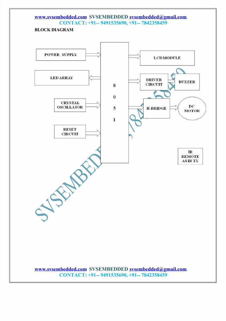
16X2 LCD is connected at the receiver end to display the speed level of the
motor and the direction. LED indication is also provided for visual indication.
This project uses regulated 5V, 500mA & 12V, 500mA power supply. 7805 and
7812 three terminal voltage regulators are used for voltage regulation. Bridge type full
wave rectifier is used to rectify the ac out put of secondary of 230/12V step down
transformer.
www.svsembedded.com SVSEMBEDDED [email protected],
CONTACT: +91-- 9491535690, +91-- 7842358459
7/30/2019 Dc Motor Speed and Direction Control Using Ir
http://slidepdf.com/reader/full/dc-motor-speed-and-direction-control-using-ir 3/3
www.svsembedded.com SVSEMBEDDED [email protected],
CONTACT: +91-- 9491535690, +91-- 7842358459
BLOCK DIAGRAM
www.svsembedded.com SVSEMBEDDED [email protected],
CONTACT: +91-- 9491535690, +91-- 7842358459