Embed Size (px)
Citation preview
www.saftronics.com
DC6DC Motor Drives
P/N X010004 REV:2
efesotomasyon.com - Control Techniques,emerson,saftronics -ac drive-servo motor
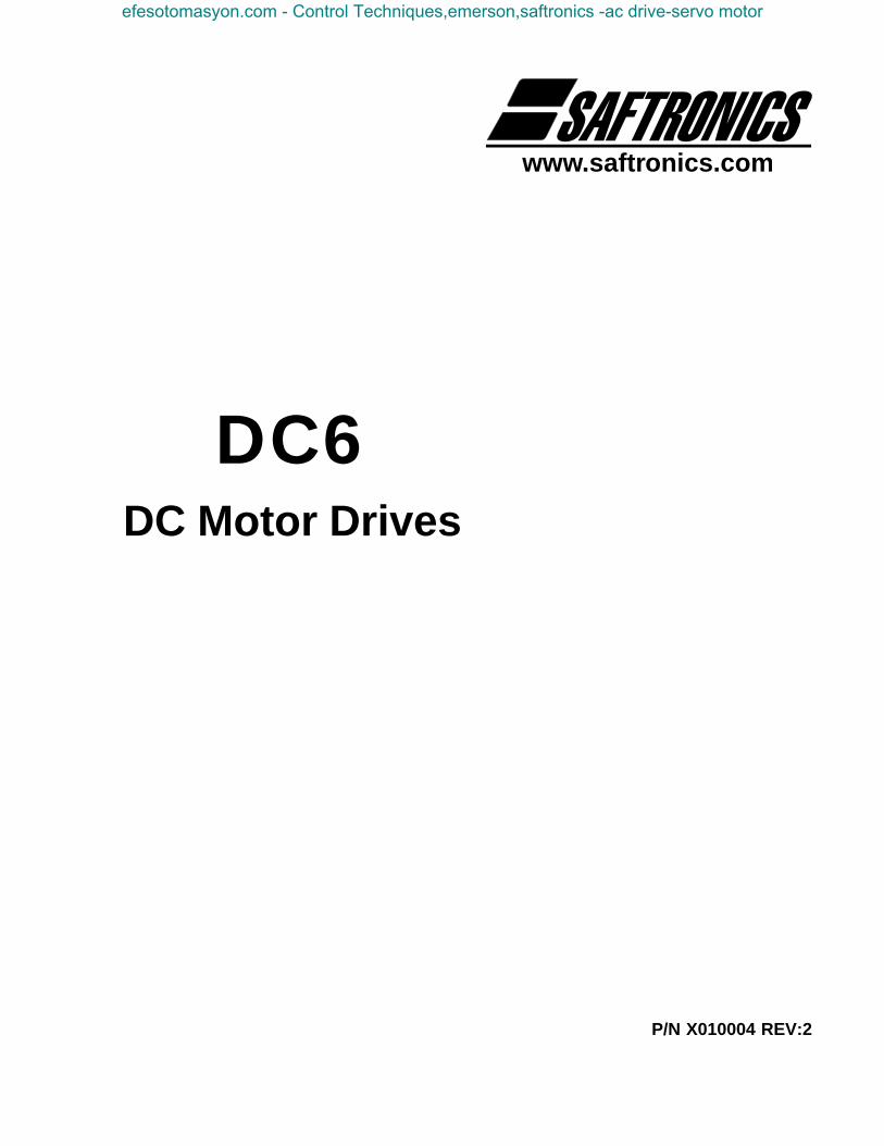
DC6 SERIESINSTRUCTION MANUAL CONTENTS
1. Description1.1 General ......................................................................................................... 11.2 Standard Features ........................................................................................ 11.3 Optional Features ......................................................................................... 11.4 Power Bridge ................................................................................................ 1
2. Installation2.1 General ......................................................................................................... 32.2 External Cabling ........................................................................................... 3
3. Startup3.1 Adjustments prior to Operation ...................................................................... 53.2 Initial Operation of the Drive Unit .................................................................. 53.3 Maximum Speed Adjustment ........................................................................ 63.4 Minimum Speed Adjustment ......................................................................... 63.5 Tach Loss Protection Check ......................................................................... 73.6 Speed Stability Adjustment ........................................................................... 73.7 Normal Current Limit Adjustment .................................................................. 73.8 Two-stage Current Limit Adjustment ............................................................. 73.9 IR Compensation .......................................................................................... 83.10 Acceleration/Deceleration Adjustment ........................................................ 83.11 Jog Speed Adjustment ................................................................................ 83.12 General ....................................................................................................... 8
4. General4.1 Block Diagram .............................................................................................. 94.2 Typical Wiring Diagram .............................................................................. 104.3 AA650MB Schematic .................................................................................. 114.4 A650 Control Schematic ............................................................................. 12
5. Burden Resistor.......................................................................................................................... 14
6. Troubleshooting.......................................................................................................................... 15
7. Spare Parts.......................................................................................................................... 17
8. Warranty.......................................................................................................................... 18
efesotomasyon.com - Control Techniques,emerson,saftronics -ac drive-servo motor
1
SAFTRONICS
1. DESCRIPTION
SAFTRONICS type DC6 SCR converters are intended to power DC motors rangingfrom 5HP to 2000 HP.
The basic converter unit consists of:a) A 6SCR power bridge.b) A single control card type AA650 mounted on the power bridge assembly.
The entire control circuit is accommodated on this card.c) Synchronizing transformer assembly, upon which is mounted a relay logic
PC board type A650-MB-2. This board is connected to the control card via aflat ribbon cable.
• Impedance-isolated armature feedback for a speed regulation of better than5%.
• Isolated current feedback using current transformers.• Visual indication of all important control points within the control card (light
emitting diodes - LED’s).• Single control card for quick replacement.• Phase rotation protection with run interlocking and indication.• Instantaneous protection against excessive current overload (ICT Current
fault trip).• Automatic resetting of ICT circuit when operating the normal STOP/START
circuit.• Stall-protection where power to the motor will cease after a stall period of
longer than 12 seconds under current limit conditions.• Adjustable maximum voltage with armature feedback.• Adjustable maximum speed with tachometer feedback.• Adjustable minimum speed.• Adjustable acceleration (1-60 seconds).• Adjustable deceleration (1-60 seconds).• Adjustable current limit to the motor.• Adjustable IR compensation.• Adjustable velocity and current loop stabilities.• Tachometer feedback loss protection i.e. the control will automatically revert
to impedance-isolated armature feedback if the tachometer fails.• Jogging facility with independent speed adjustment.• 2-stage current limit for high initial starting torque requirement .• Tachometer feedback for a speed regulation of better than 1.0%.
• Parallel 12-pulse operation.• Multi-drive systems with accurate load sharing better than 3%.• Input programming for follower drive applications.• Constant kW/HP operation with a field current regulator.• Constant current field regulator.• Remote control station(s).• Digital speed control for better than 0.1% regulation.
Standard Protective Features• Fast acting fuses.
1.1 General
1.2 Standard Features
1.4 Power Bridge
1.3 Optional Features
efesotomasyon.com - Control Techniques,emerson,saftronics -ac drive-servo motor
2
SAFTRONICS
• Instantaneous protection against excessive current overload (Electronic pro-tection - ICT).
• SCR protection against excessive dv/dt and over-voltage by means of indi-vidual R-C circuitry.
• Power bridge overtemperature protection to cut-out when stack temperatureexceeds 85 degrees C (+/- 5o).
Optional Protective FeaturesBlower for cooling the DC motor, supplied via a contactor with thermal overload andusing protection interlocked with the run control circuitry.
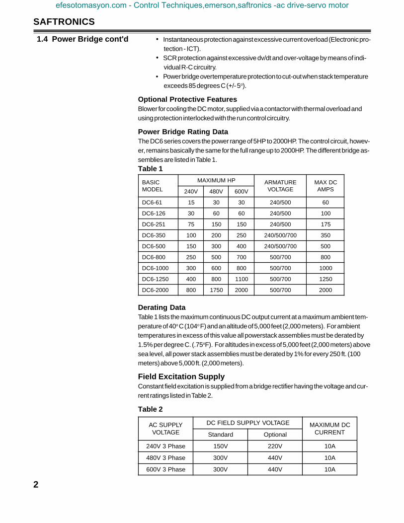
Power Bridge Rating DataThe DC6 series covers the power range of 5HP to 2000HP. The control circuit, howev-er, remains basically the same for the full range up to 2000HP. The different bridge as-semblies are listed in Table 1.Table 1
Derating DataTable 1 lists the maximum continuous DC output current at a maximum ambient tem-perature of 40o C (104o F) and an altitude of 5,000 feet (2,000 meters). For ambienttemperatures in excess of this value all powerstack assemblies must be derated by1.5% per degree C. (.75oF). For altitudes in excess of 5,000 feet (2,000 meters) abovesea level, all power stack assemblies must be derated by 1% for every 250 ft. (100meters) above 5,000 ft. (2,000 meters).
Field Excitation SupplyConstant field excitation is supplied from a bridge rectifier having the voltage and cur-rent ratings listed in Table 2.
Table 2
1.4 Power Bridge cont'd
CISABLEDOM
PHMUMIXAM ERUTAMRAEGATLOV
CDXAMSPMAV042 V084 V006
16-6CD 51 03 03 005/042 06
621-6CD 03 06 06 005/042 001
152-6CD 57 051 051 005/042 571
053-6CD 001 002 052 007/005/042 053
005-6CD 051 003 004 007/005/042 005
008-6CD 052 005 007 007/005 008
0001-6CD 003 006 008 007/005 0001
0521-6CD 004 008 0011 007/005 0521
0002-6CD 008 0571 0002 007/005 0002
YLPPUSCAEGATLOV
EGATLOVYLPPUSDLEIFCD CDMUMIXAMTNERRUCdradnatS lanoitpO
esahP3V042 V051 V022 A01
esahP3V084 V003 V044 A01
esahP3V006 V003 V044 A01
efesotomasyon.com - Control Techniques,emerson,saftronics -ac drive-servo motor

3
SAFTRONICS
2.1 General2. INSTALLATION
Unless the unit has been specifically designed for poor environmental conditions, itmust be installed in an area where the following conditions exist:
a) Ambient temperature does not exceed 40°C (104°F)b) Ambient temperature is not less than 10°C (50°F)c) Altitude above sea level in excess of 5,000 ft. (2,000 meters) must be taken
into account as in Derating Data,Section 1.4.d) Ambient air is reasonably clean and dry. It must be free of flammable or com-
bustible vapors, steam or corrosive gases.e) The clearance around the cabinet must be sufficiently large to:
i) Provide full accessibility to the front.ii) Provide a non-restricted airflow (with a minimum of 1" clearance) from
the intake and exhaust ventilation louvers.
It is most important that the AC supply to the unit is of the correct voltage and currentrating. It should be kept in mind that where the specified drive unit voltages and/or cur-rents are not available, an interstage transformer will be necessary. All external con-nections must be made according to the Engineering drawing supplied. All power andcontrol cable ratings should be referred to the National Electrical Code Handbook.
Cable Current RatingsTable 3 lists the maximum continuous current which the AC and DC cables must car-ry for the various drive types. If the system uses a transformer, then the AC ratingsare for the transformer secondary. Primary ratings must be determined by the trans-former rating.
Table 3
Motor Field Cable Current RatingsMotor field cable current ratings are determined by the motor being used. This cannormally be ascertained by referring to the motor nameplate. A cable rating of 20amps should be adequate for the full range up to 1500HP. The cable insulation ratingshould not be less than 600V.
2.2 External Cabling
EPYTEVIRDERUTAMRAMUMIXAM
)GVA(SPMAYLPPUSESAHP3
)SMR(SPMA
16-6CD 06 94
621-6CD 521 301
152-6CD 152 402
053-6CD 053 682
005-6CD 005 804
008-6CD 008 356
0001-6CD 0001 618
0521-6CD 0521 0201
0002-6CD 0002 2361
efesotomasyon.com - Control Techniques,emerson,saftronics -ac drive-servo motor
4
SAFTRONICS
2.2 External Cablingcont'd
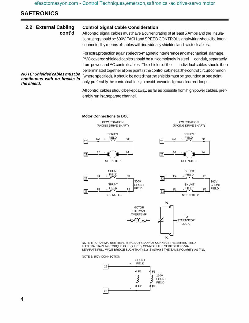
Motor Connections to DC6
20
21
SERIESFIELD S1
A1
S2
A2
+
-
SEE NOTE 1
CCW ROTATION(FACING DRIVE SHAFT)
20
21
SERIESFIELD S1
A2
S2
A1
+
-
SEE NOTE 1
CW ROTATION(FACING DRIVE SHAFT)
Control Signal Cable ConsiderationAll control signal cables must have a current rating of at least 5 Amps and the insula-tion rating should be 600V. TACH and SPEED CONTROL signal wiring should be inter-connected by means of cables with individually shielded and twisted cables.
For extra protection against electro-magnetic interference and mechanical damage,PVC covered shielded cables should be run completely in steel conduit, separatelyfrom power and AC control cables. The shields of the individual cables should thenbe terminated together at one point in the control cabinet at the control circuit common(where specified). It should be noted that the shields must be grounded at one pointonly, preferably the control cabinet, to avoid unwanted ground current loops.
All control cables should be kept away, as far as possible from high power cables, pref-erably run in a separate channel.
22
23
F4
F1
F3
F2
+
-
SHUNTFIELD
SHUNTFIELD
300VSHUNTFIELD
SEE NOTE 2
22
23
F4
F1
F3
F2
+
-
SHUNTFIELD
SHUNTFIELD
300VSHUNTFIELD
SEE NOTE 2
MOTORTHERMAL
OVERTEMP
P1
P2
TOSTART/STOP
LOGIC
NOTE 1: FOR ARMATURE REVERSING DUTY, DO NOT CONNECT THE SERIES FIELD.IF EXTRA STARTING TORQUE IS REQUIRED, CONNECT THE SERIES FIELD VIASEPARATE FULL-WAVE BRIDGE SUCH THAT (S1) IS ALWAYS THE SAME POLARITY AS (F1).
NOTE 2: 150V CONNECTION
22
23
SHUNTFIELD
F1
F2 F4
F3
+
-
150VSHUNTFIELD
NOTE: Shielded cables must becontinuous with no breaks inthe shield.
efesotomasyon.com - Control Techniques,emerson,saftronics -ac drive-servo motor
5
SAFTRONICS
3. STARTUPWhen all cable connections have been thoroughly checked out according to the Engi-neering drawing, Power may be applied to the drive unit, but the Start circuit must notbe operated at this point.
The following adjustments should be made on the AA650 control card:RV6 - MAXIMUM SPEED (tach feedback) -Fully counter-clockwiseRV3 - RATE I (Acceleration Rate) -Fully clockwiseRV4 - RATE II (Deceleration Rate) -Fully clockwiseRV5 - STABILITY (Speed) -Mid PositionRV9 - CURRENT LIMIT ¼ clockwiseRV7 - MINIMUM SPEED -Fully counter-clockwiseRV8 - IR COMPENSATION -Fully counter-clockwiseRV2 - AV (Max. Armature Voltage) -Fully counter-clockwiseRV1 - CS (Current Stability - Factory Set) -Mid position approx.
The state of the LED's on the AA650 control card should be as follows:-V (-12 Volt Supply) -Glowing brightlyR (Run indication) -OffDV (Speed Reference) -OffVA (Speed Error Amplifier Output) -OffCA (Current Error Amplifier Output) -OffST (Stall Sensing) -Glowing brightlyTR (Trip Circuit) -Off or On*2S (2-Stage Current Limit Circuit) -OffΦPhase Rotation Indication -Glowing brightly+V (+12 Volt Supply) -Glowing brightlyΦ1, Φ2, Φ3 (Comparator Output Indication) -Glowing dimly
*The TRIP LED should come on after the run command is applied to the drive.
Phase Rotation Correct IndicationIf the phase rotation LED is not glowing, the supply should be disconnected and anytwo phases of the supply reversed. When power is restored, this LED should glowbrightly. If this LED remains in the OFF condition, the supply to the drive should bechecked for the correct phase to phase voltage.
Considerations before Running the MotorPrior to running the DC motor, ensure that the motor is free to rotate at maximumspeed without damage to the machine to which it is coupled. It is preferable to de-cou-ple the motor from the machine if possible, as this will ensure no possible damage tothe machine. Where compound motors are used, it is preferable to by-pass the seriesfield winding until the drive unit has been completely set up.
Before running the drive, it will be necessary to carry out the following:a) Operator’s speed control set to its zero-position. Where motorized potenti-
ometers are used, this can be done by operating the Increase/Deceasespeed buttons.
3.1 Adjustment Prior ToOperation
NOTE: If any of the LED’s do notconform to the pre-start list , donot immediately suspect theAA650 card of being faulty. Firstcheck out all external connec-tions for short circuits and crossconnections etc. The AA650card has been thoroughly testedat the factory and it will be un-likely that this card would be atfault.
3.2 Initial Operation of theDrive Unit
efesotomasyon.com - Control Techniques,emerson,saftronics -ac drive-servo motor
6
SAFTRONICS
b) Where tachogenerator feedback is used, it will not initially be certain whetherthe signal is of the correct polarity. It is, therefore, suggested that the tacho-generator be electrically disconnected temporarily. The drive will automati-cally revert to the correct polarity armature feedback, and the drive can beset up initially on this feedback signal.
c) Ensure that the Shunt Field voltage is at the correct maximum value.
Press the Start pushbutton and slowly adjust the Operator’s Speed control in a clock-wise direction until the motor starts to turn and accelerate up to the set speed.
Check that the motor is turning in the correct direction. If the motor is not turning in thecorrect direction, switch off the power and reverse the connections to the motor’sshunt field.
Restore power to the drive, and run the motor once more. The motor should now turnin the correct direction.
While the motor is running, check the polarity of the voltage generated by the tach.When this polarity has been determined, switch off the drive unit and re-connect thetach to the drive with the polarity indicated in this manual or in the Engineering Draw-ing supplied if a standard non-modified DC6 was purchased.
Restore power to the drive and run once more. The motor should be running under theinfluence of the tach, and the ST light should be glowing brightly.
If the motor accelerates to the absolute maximum speed, regardless of speed setting,this will indicate that the tach voltage polarity is incorrect, and should be rechecked.
With Armature FeedbackThis adjustment should be carried out with the tach disconnected from the drive unit, ifthis option is used.
Start the drive and set the operator’s speed control to maximum. Adjust the control“AV” (RV2) on the control card for the correct maximum armature voltage indicated onthe motor nameplate. Once this adjustment has been carried out, the tach connec-tions can be restored to the drive unit.
With Tach Feedback(Optional)Set the operator’s Speed Control to maximum, and check the motor speed by holdinga hand tach to the motor shaft or by checking the tachogenerator voltage. The stan-dard tach type 5PY used by Saftronics is rated at 50 Volts/1000RPM. This should,however, be confirmed by referring to the tach nameplate. It will also be noted that withthe Speed Control set at maximum, the DV lamp on the AA650 card will glow brightly.Adjust the Maximum speed control,RV6 on the AA650 card, for the required maxi-mum speed; usually 1750RPM, or 87.5 Volts on the 5PY tach.
Set the operator’s Speed Control to zero while the drive unit is on, and adjust the Mini-mum speed control, RV7 on the AA650 card, for the correct minimum speed.
NOTE: In de-energized state,the field economy circuit will beoperation. The field voltage willbe at 2/3 normal level until theDC6 is started.
NOTE: The Trip circuit mayoperate at 12 second intervalsduring this procedure and re-move power from the motor.This is normal, and the Stop/Start circuit should be re-acti-vated after such a trip. Once thecorrect maximum motor currentand speed has been set up, theTrip circuit will act correctly,that is only remove power fromthe motor if it has stalled for aperiod longer than 12 secondsunder maximum current condi-tions.
CAUTION: Dangerous voltagewill be present if power is notremoved.
Note: If the tachometer is 100V/1000 rpm and the motor is 1750rpm, then put an 82K resistor inseries with the tach lead.
3.3 Maximum SpeedAdjustment
3.4 Minimum SpeedAdjustment
efesotomasyon.com - Control Techniques,emerson,saftronics -ac drive-servo motor
7
SAFTRONICS
When steps 2.3.5, 2.3.6, and 2.3.7 have been carried out, it will be possible to checkthis feature as follows:
With the motor running at half speed, remove one of the tach connections fromthe drive. The control should now revert to impedance-isolated armature volt-age feedback and the motor speed should only change marginally (it can eitherincrease or decrease depending on the setting of “AV”, RV2, with respect to theMaximum speed adjustment).
When in operation, the drive unit regulator may be unstable. This becomes evidentwhen the motor speed is unstable or erratic. The Stab control, RV5 on the AA650 con-trol card, should be adjusted whenever necessary so that the motor speed is smoothand stable, with very little under or overshoot with speed changes.
With the motor running normally, at maximum speed, adjust the Current Limit controltowards minimum until the motor speed starts dropping. Stop the drive unit, andswitch off the AC supply. Disconnect the field supply from the motor, and jam theshaft to prevent it from turning. Field loss relay protection, FLR must be bypassed inthe 120 vac control logic during this set up.
Restore power to the drive, set the speed control to minimum and press the Startpushbutton. Slowly increase the speed control to maximum. The motor armature cur-rent will rise to a low value, as indicated by an ammeter and the stall LED. ST will gooff, indicating that there is a 12-second period in which the current limit can be set be-fore the trip circuit comes into operation. Adjust the Current Limit (CL) control slowlytoward motor nameplate full load current rating.
NOTE: The TRIP circuit may frequently operate during this adjustment, butthis is quite normal as it will depend on how long the adjustment takes to becarried out.
The TRIP circuit prevents the motor from drawing high current for excessive periods,while in the stall condition. The Start/Stop circuit should be re-activated to clear thiscondition.
After set up disconnect power, remove the object jamming the shaft, and re-installfield cables and field loss protection circuit.
With the two-stage current limit feature, it will be essential that the Burden Resistor besized to give the desired break away current. Standard drives are supplied with Bur-den Resistors sized for approximately 150% of full load current of the motor, with fullclockwise rotation of the current limit potentiometer.
The normal running current limit point can be set by inserting a resistor of a specifiedvalue in place of the 0 ohm Resistor supplied with the standard card. This resistor isR214 on the AA650 control card.
For a 200% break away current, the normal running current limit can be set by choos-ing a resistor from the table below:
3.5 Tach Loss ProtectionCheck
3.6 Speed StabilityAdjustment
3.7 Normal Current LimitAdjustment
NOTE: The motor may stop com-pletely, but this is quite normal.
NOTE: Compound Motors gen-erate considerable torque evenwithout SHUNT FIELD excita-tion, so it is advisable to leavethe series field winding discon-nected from the armature circuitas previously suggested (seesection 3.1).
3.8 Two-stage CurrentLimit Adjustment
(Optional)
efesotomasyon.com - Control Techniques,emerson,saftronics -ac drive-servo motor

8
SAFTRONICS
To set current limit with this option (two stage current limit) follow the proceedure laidout in section 3.7 above.
After the current limit has been set to the break away current, the drive automaticallyadjusts the current limit setting to the normal running limit after the 2S led has turnedon.
GeneralIR compensation must only be used with Armature Feedback control and shouldnever be used with Tach Feedback control. Therefore, where tach feedback is used,this control must remain in the full counter-clockwise position. Furthermore, the motormust be coupled to the machine before this adjustment is carried out. The purpose ofIR Compensation is to compensate for IR losses in the motor such that low speedholding capability is improved with armature feedback control.
IR Compensation AdjustmentWith the drive in operation at half speed, slowly adjust the IR compensation control(RV8) clock-wise until there are signs of instability with quick speed changes from25% to 75%. Slowly adjust the IR compensation control towards minimum again untilall signs of instability have disappeared. This will be the maximum amount of the IRcompensation that the machine will allow with good stability. It should be kept in mindthat where the machine is new or reconditioned, it may be “tight” initially, and it may befound necessary to reduce the amount of IR compensation at a later stage to preventinstability.
The acceleration and deceleration control RATE I and RATE II respectively, can be ad-justed for the required acceleration and deceleration to suit the application.
Where this feature is supplied, the Jog pushbutton must be pressed and the JogSpeed control on the A650-MB-2 control board must be adjusted for the desired jogspeed.
When all adjustments have been carried out, reconnect the series (compound) field(see p4). It must be ensured that the series field is correctly connected such that it as-sists the main shunt field of the motor and not oppose it.
3.9 IR Compensation
3.10 Acceleration/Deceleration Adjustment
3.12 General
3.11 Jog SpeedAdustment
%gninnuRtnerruC
ecnatsiseRsmho
002 0
051 033
031 065
021 086
001 0001
efesotomasyon.com - Control Techniques,emerson,saftronics -ac drive-servo motor
9
SAFTRONICS
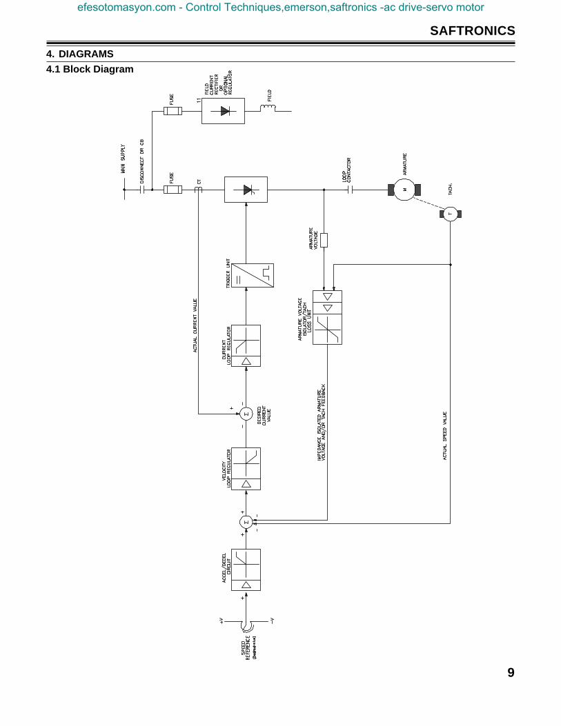
4. DIAGRAMS
4.1 Block Diagram
efesotomasyon.com - Control Techniques,emerson,saftronics -ac drive-servo motor
10
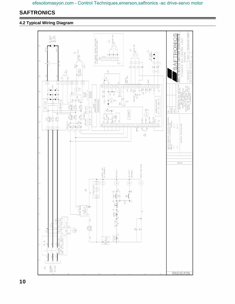
SAFTRONICS
4.2 Typical Wiring Diagram
efesotomasyon.com - Control Techniques,emerson,saftronics -ac drive-servo motor
11
SAFTRONICS
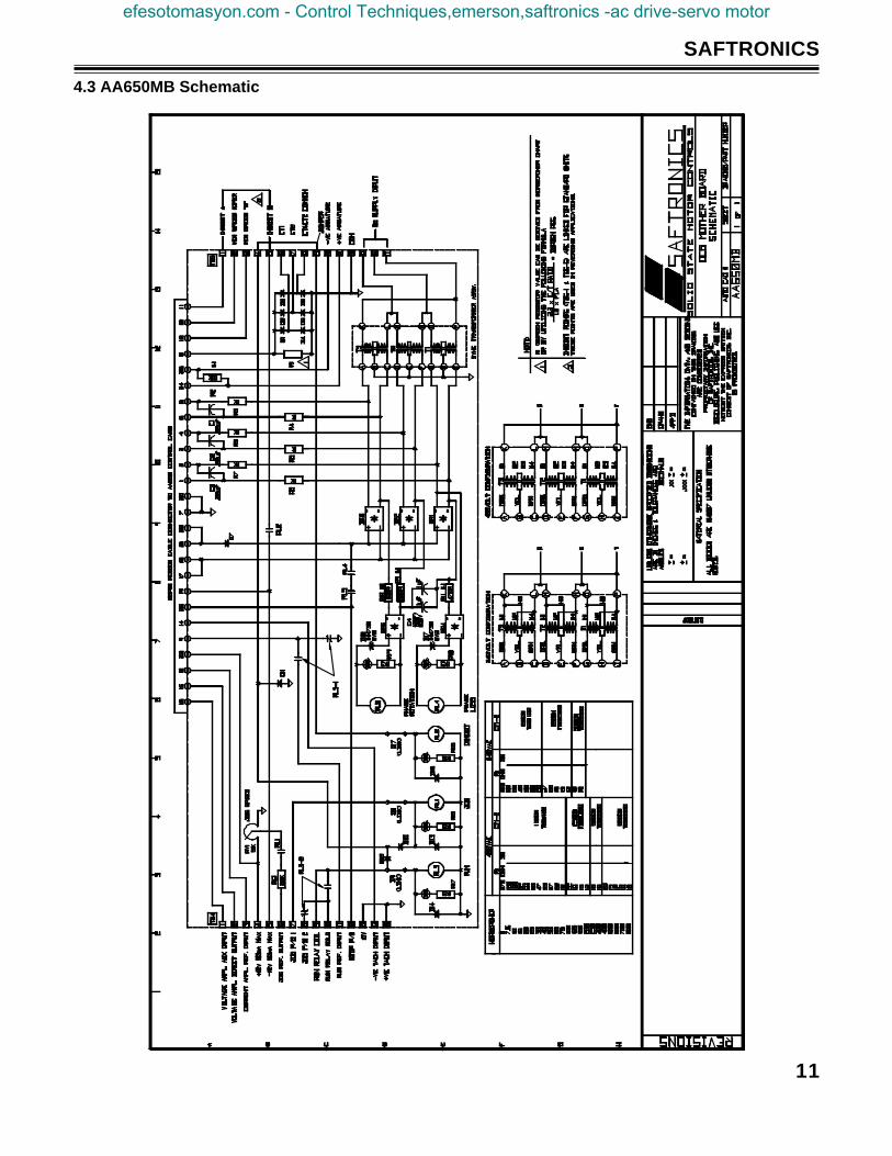
4.3 AA650MB Schematic
efesotomasyon.com - Control Techniques,emerson,saftronics -ac drive-servo motor
12
SAFTRONICS
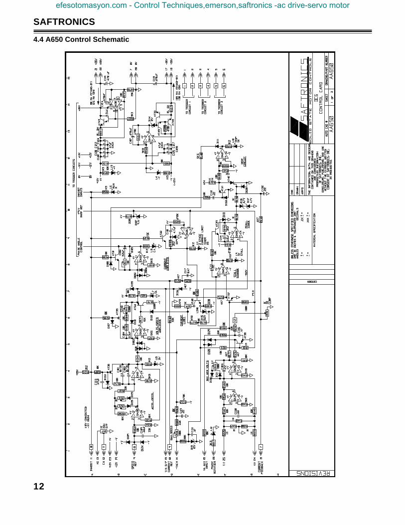
4.4 A650 Control Schematic
efesotomasyon.com - Control Techniques,emerson,saftronics -ac drive-servo motor
13
SAFTRONICS
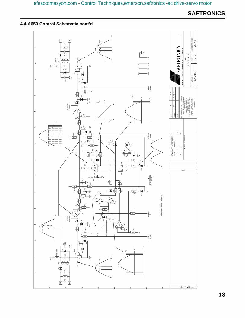
4.4 A650 Control Schematic cont'd
67 4
2 3
-V+V
R6 R30
R24
R23
R22
R25
R18
2K2
4K7
22K
100K
15K
D20
D16
C2
10u
F
15K
AT5
D18
D6
AT7
AT8
TP13
D5
C7
.022
R42D
4
R44
T1G
1
K1
-V
X-C
OU
PLE
INPU
T 1
-V
+V
X-C
OU
PLE
OU
TPU
T 1
D28 L1
R12
R10
R19
R33
R35
R34
R8
R31R14
R13
R36
R11
1K5
1K5
47K
4K7
15K
15K
D21
AT2
100K 2K
24K
7
5K6
56K
56K
+V
X-C
OU
PLE
OU
TPU
T 7 X
- CO
UPL
EIN
PUT
7
R37
R38
R39
1KD
17
D9
AT6
D23
AT9
AT1
0
TP14
C5
10u
F
D10
C6
.022
D11
G4
K4
R45
R43
-V-V
-V
C3
-V-V
6
74
23
-V+
V
AT1
D15
D2
C4
.22
D14
R9
R1
1K5
R32
R26
R2
68K
R7 1K5
D8R1
7
10K
+V
-V
RAM
PRE
FIN
HIB
ITSI
GN
AL
R28
R27
R5
10K
+V
D7
4.7V
D19
-V
R29
D24
D25
SYN
CH
RON
IZIN
GIN
PUT
CO
NTR
OL
SIG
NA
L
0V
0V
450 uSEC
0V
0V
INH
IBIT
SIG
NA
L
0V
10V
-10V
0V0V
-10V
10V 0V
+12
V-1
2V0V
+12
V-1
2V
TRIG
GER
CIR
CU
ITS
A, B
, C A
S A
BO
VE
+26
V
+26
V9.
1V
9.1V
+26
V
+26
V
+26
V
D3
AT3
D22
AT4
D12
+26
V
.1
67 4
2 3
-V+V
6
-V+V
67 4
2 3
-V+V
220R
.1
15K
15K
4K7
.122
0R
100R
1/2
W
QA
3
QA
2
QA
61K
22K
22K
10K
10R
8
REVISIONS
HGF
CUSTOMER
3
EDCBA
12
45
67
AU
TO C
AD
#
SO
LID
ST
AT
E M
OT
OR
CO
NT
RO
LS
MA
TERI
AL
SPEC
IFIC
ATI
ON
--
--
==
==
++
=
AN
GLE
S
DEC
IMA
LSA
RE IN
INC
HES
& T
OLE
RAN
CES
ARE
:U
NLE
SS O
THER
WIS
E SP
ECIF
IED
DIM
ENSI
ON
S
.XX
X
.XX
CO
NSE
NT
OF
SAFT
RON
ICS,
INC
.IS
PRO
HIB
ITED
.
WIT
HO
UT
THE
EXPR
ESS
WRI
TTEN
DIS
CLO
SURE
, PU
BLI
SHIN
G, A
ND
USE
OF
SAFT
RON
ICS,
INC
.PR
OPR
IETA
RY IN
FORM
ATI
ON
ARE
CO
NSI
DER
EDC
ON
TAIN
ED O
N T
HIS
DRA
WIN
GTH
E IN
FORM
ATI
ON
, DA
TA, A
ND
DES
IGN
S
APP
'D
DRA
WN
ENG
DRA
WIN
G/P
ART
NU
MB
ER
OF
SHEE
T
139
1011
1214
15
SAFT
RO
NIC
S
BP
07 S
EP 9
0
JM07
SEP
90
DC
6C
ON
TRO
L C
ARD
AA
6502
23
AA
650
efesotomasyon.com - Control Techniques,emerson,saftronics -ac drive-servo motor
14
SAFTRONICS
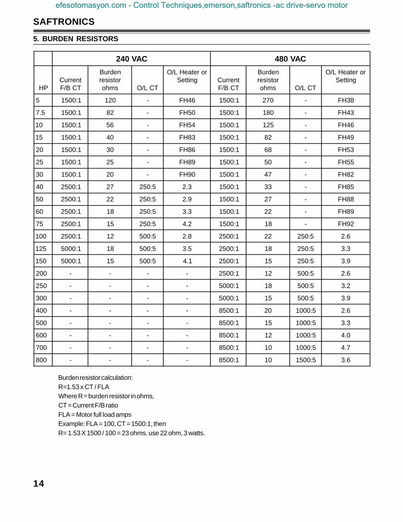
Burden resistor calculation:R=1.53 x CT / FLAWhere R = burden resistor in ohms,CT = Current F/B ratioFLA = Motor full load ampsExample: FLA = 100, CT = 1500:1, thenR= 1.53 X 1500 / 100 = 23 ohms, use 22 ohm, 3 watts.
5. BURDEN RESISTORS
CAV042 CAV084
PHtnerruC
TCB/F
nedruBrotsiser
smho TCL/O
roretaeHL/OgnitteS tnerruC
TCB/F
nedruBrotsiser
smho TCL/O
roretaeHL/OgnitteS
5 1:0051 021 - 64HF 1:0051 072 - 83HF
5.7 1:0051 28 - 05HF 1:0051 081 - 34HF
01 1:0051 65 - 45HF 1:0051 521 - 64HF
51 1:0051 04 - 38HF 1:0051 28 - 94HF
02 1:0051 03 - 68HF 1:0051 86 - 35HF
52 1:0051 52 - 98HF 1:0051 05 - 55HF
03 1:0051 02 - 09HF 1:0051 74 - 28HF
04 1:0052 72 5:052 3.2 1:0051 33 - 58HF
05 1:0052 22 5:052 9.2 1:0051 72 - 88HF
06 1:0052 81 5:052 3.3 1:0051 22 - 98HF
57 1:0052 51 5:052 2.4 1:0051 81 - 29HF
001 1:0052 21 5:005 8.2 1:0052 22 5:052 6.2
521 1:0005 81 5:005 5.3 1:0052 81 5:052 3.3
051 1:0005 51 5:005 1.4 1:0052 51 5:052 9.3
002 - - - - 1:0052 21 5:005 6.2
052 - - - - 1:0005 81 5:005 2.3
003 - - - - 1:0005 51 5:005 9.3
004 - - - - 1:0058 02 5:0001 6.2
005 - - - - 1:0058 51 5:0001 3.3
006 - - - - 1:0058 21 5:0001 0.4
007 - - - - 1:0058 01 5:0001 7.4
008 - - - - 1:0058 01 5:0051 6.3
efesotomasyon.com - Control Techniques,emerson,saftronics -ac drive-servo motor
15
SAFTRONICS
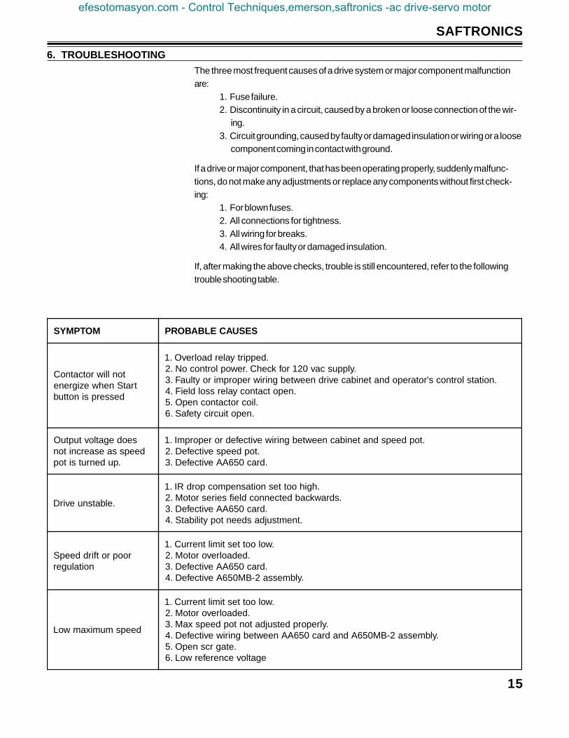
6. TROUBLESHOOTING
The three most frequent causes of a drive system or major component malfunctionare:
1. Fuse failure.2. Discontinuity in a circuit, caused by a broken or loose connection of the wir-
ing.3. Circuit grounding, caused by faulty or damaged insulation or wiring or a loose
component coming in contact with ground.
If a drive or major component, that has been operating properly, suddenly malfunc-tions, do not make any adjustments or replace any components without first check-ing:
1. For blown fuses.2. All connections for tightness.3. All wiring for breaks.4. All wires for faulty or damaged insulation.
If, after making the above checks, trouble is still encountered, refer to the followingtrouble shooting table.
MOTPMYS SESUACELBABORP
tonlliwrotcatnoCtratSnehwezigrene
desserpsinottub
.deppirtyalerdaolrevO.1.ylppuscav021rofkcehC.rewoplortnocoN.2
.noitatslortnocs'rotarepodnatenibacevirdneewtebgniriwreporpmiroytluaF.3.nepotcatnocyalerssoldleiF.4
.liocrotcatnocnepO.5.nepotiucricytefaS.6
seodegatlovtuptuOdeepssaesaercniton
.pudenrutsitop
.topdeepsdnatenibacneewtebgniriwevitcefedroreporpmI.1.topdeepsevitcefeD.2
.drac056AAevitcefeD.3
.elbatsnuevirD
.hgihoottesnoitasnepmocpordRI.1.sdrawkcabdetcennocdleifseiresrotoM.2
.drac056AAevitcefeD.3.tnemtsujdasdeentopytilibatS.4
rooprotfirddeepSnoitaluger
.woloottestimiltnerruC.1.dedaolrevorotoM.2
.drac056AAevitcefeD.3.ylbmessa2-BM056AevitcefeD.4
deepsmumixamwoL
.woloottestimiltnerruC.1.dedaolrevorotoM.2
.ylreporpdetsujdatontopdeepsxaM.3.ylbmessa2-BM056Adnadrac056AAneewtebgniriwevitcefeD.4
.etagrcsnepO.5egatlovecnereferwoL.6
efesotomasyon.com - Control Techniques,emerson,saftronics -ac drive-servo motor
16
SAFTRONICS
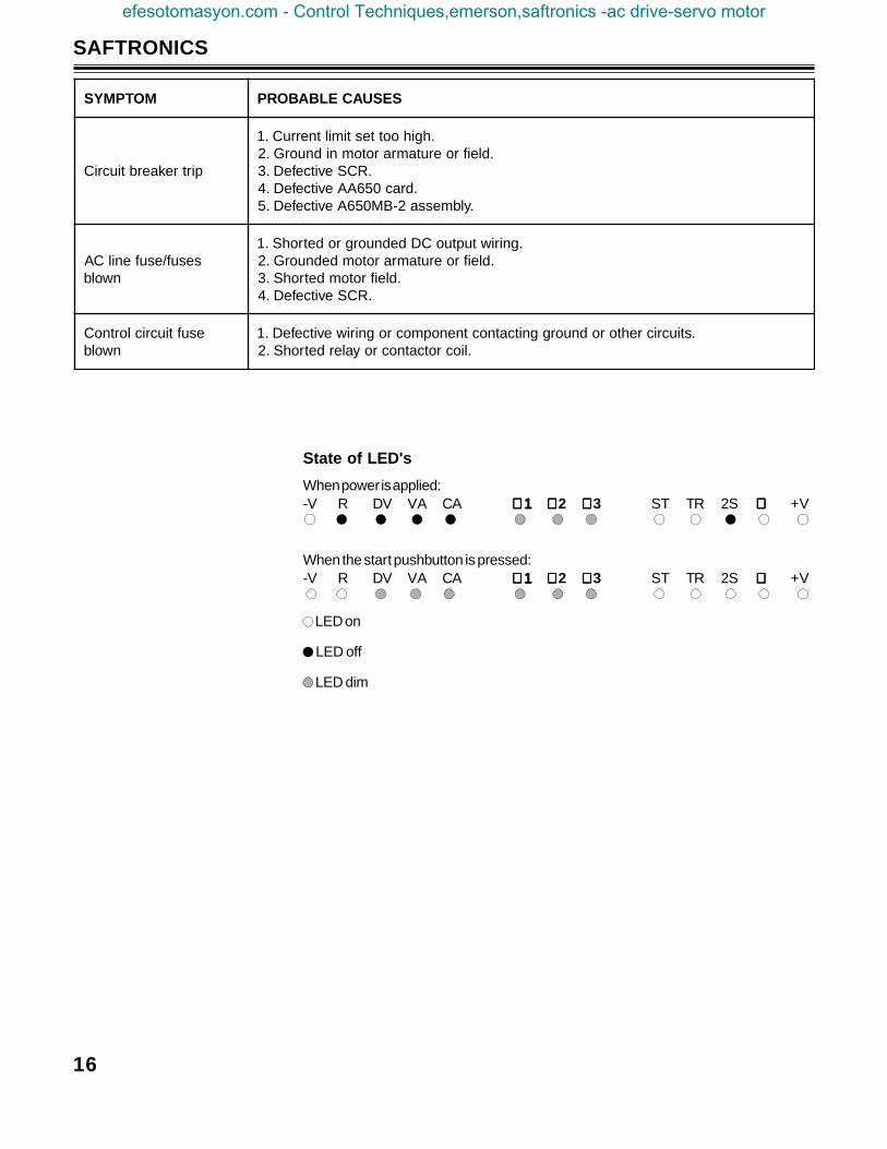
When power is applied:-V R DV VA CA ∅1∅1∅1∅1∅1 ∅∅∅∅∅ 2 ∅∅∅∅∅ 3 ST TR 2S ∅∅∅∅∅ +V
When the start pushbutton is pressed:-V R DV VA CA ∅1∅1∅1∅1∅1 ∅∅∅∅∅ 2 ∅∅∅∅∅ 3 ST TR 2S ∅∅∅∅∅ +V
State of LED's
LED on
LED off
LED dim
MOTPMYS SESUACELBABORP
pirtrekaerbtiucriC
.hgihoottestimiltnerruC.1.dleifroerutamrarotomnidnuorG.2
.RCSevitcefeD.3.drac056AAevitcefeD.4
.ylbmessa2-BM056AevitcefeD.5
sesuf/esufenilCAnwolb
.gniriwtuptuoCDdednuorgrodetrohS.1.dleifroerutamrarotomdednuorG.2
.dleifrotomdetrohS.3.RCSevitcefeD.4
esuftiucriclortnoCnwolb
.stiucricrehtorodnuorggnitcatnoctnenopmocrogniriwevitcefeD.1.liocrotcatnocroyalerdetrohS.2
efesotomasyon.com - Control Techniques,emerson,saftronics -ac drive-servo motor

17
SAFTRONICS
7. SPARE PARTS
TRAPNOITPIRCSED
REBMUNLEDOM
16-6CD 621-6CD 152-6CD 053-6CD 005-6CD 008-6CD
draClortnoCecirPtsiL
ytitnauQdednemmoceR
056AA0051$
1
056AA0051$
1
056AA0051$
1
056AA0051$
1
056AA0051$
1
056AA0051$
1
draoBrehtoMV042V084
ecirPtsiLytitnauQdednemmoceR
100043A200043A
006$1
100043A200043A
006$1
100043A200043A
006$1
100043A200043A
006$1
100043A200043A
006$1
100043A200043A
006$1
draCnoisserppuSecirPtsiL
ytitnauQdednemmoceR
2-4901AA501$
1
2-4901AA501$
1
2-4901AA501$
1
2-4901AA501$
1
2-4901AA501$
1
2-4901AA501$
1
elbaCnobbiRecirPtsiL
ytitnauQdednemmoceR
63-0062W53$
1
63-0062W53$
1
63-0062W53$
1
63-0062W53$
1
63-0062W53$
1
63-0062W53$
1
hctiwSpmetrevOkcatSecirPtsiL
ytitnauQdednemmoceR
--200325S3002$
1
--200325S3002$
1
--200325S3002$
1
--200325S3002$
2
--200325S3002$
2
--200325S3002$
2
esuFeniLCAecirPtsiL
ytitnauQdednemmoceR
--300206F9063$
3
--300206F1145$
3
--300206F0276$
3
--300206F0276$
3
--300206F3239$
3
--300206F52
861$3
RCSecirPtsiL
ytitnauQdednemmoceR
A60PS01N051$
3
A60PS01N051$
3
01PS02N582$
3
254827N522$
6
254617N042$
6
221917N793$
6
egdirBdleiFecirPtsiL
ytitnauQdednemmoceR
200013D33$
1
200013D33$
1
200013D33$
1
200013D33$
1
200013D33$
1
200013D33$
1
SYALERSSOLDLEIF
GNITAR REBMUNTRAP ECIRPTSIL
spmA0.1-52.0 100054A 511$
spmA0.4-0.1 200054A 511$
spmA0.01-0.4 300054A 511$
spmA0.6-0.2 400054A 511$
efesotomasyon.com - Control Techniques,emerson,saftronics -ac drive-servo motor
18
SAFTRONICS
8. WARRANTY
Saftronics warrants to buyer that products, and any services furnished hereunder willbe free from defects in material, workmanship and title, and will be of the kind andquality specified in the quotation. The foregoing shall apply only to failures to meetsaid warranties (excluding any defects in title) which appear within one year from thedate of shipment hereunder, provided, however, that if buyer, in the course of its regu-lar and usual business, transfers title to or leases such products (including equipmentincorporating such products) to a third party, such period shall run until one year fromsuch transfer or lease or eighteen months from shipment by Saftronics whichever oc-curs first. The warranties and remedies set forth herein are conditioned upon (a) prop-er storage, installation, use and maintenance, and conformance with any applicablerecommendations of Saftronics and, (b) buyer promptly notifying Saftronics of any de-fects and, if required, promptly making the product available for correction.
If any products or services fails to meet the foregoing warranties (except title),Saftronics shall thereupon correct any such failure either, at its option, (i) by repairingany defective or damaged part or parts of the products, or (ii) by making availableFOB Saftronics plant or other point of shipment, any necessary repaired or replace-ment parts. The preceding paragraph sets forth the exclusive remedies for claims(except as to title) based on defect in or failure of products or services, whether claimin contract or tort (including negligence) and however instituted. Upon expiration ofthe warranty period, all such liability shall terminate. The foregoing warranties are ex-clusive and in lieu of all other warranties, whether written, oral, implied or statutory. Noimplied statutory warranty of merchantability or fitness for particular purpose shall ap-ply and Saftronics will not be liable for any consequential damage arising from anyproduct defect or failure to deliver on time. Saftronics does not warrant any productsor services of others which buyer has designated.
efesotomasyon.com - Control Techniques,emerson,saftronics -ac drive-servo motor