Embed Size (px)
Citation preview
OpticalCOM Isolator
INPUT
12--24VDC
V+
To LE D
Internal module circuitry
COM
CC
0
1
2
3
4
5
6
7
12--24VDC
Internallyconnected
0
4
8
6
2
0 10 20 30 40 50 55
Ambient Temperature (°C/°F )32 50 68 86 104 122131
°C°F
Derating ChartPoints
+
C
C
0
4
1
5
2
6
3
7
10.2--26.4VDC4--12mA
D2--08ND3
IN 12--24
D2--08ND3
VDC0123
4567
+
-
-
+ -
+-
Sink
Source
Sink
Source
A
B
20--28VDC8mA
IN 24
D2--16ND3--2
VDC0123
4567
CA
4
5
6
7
CB
4
5
63
2
1
0
NC
3
2
1
0
7
CLASS2
OpticalCOM Isolator
Derating Chart
INPUT
24 VDC
V+
To LE D
Internal module circuitry
0
1
2
3
5
6
7
NC
0
1
2
3
CB
4
5
6
7
CA
4
0
1
1
8
4
2
6Points
0 10 20 30 40 50 55
Ambient Temperature (°C/°F )32 50 68 86 104 122131
°C°F
+
+
+
+-
-
-
+-
+--Sink
Source24 VDC
Sink
Source
SinkSource24 VDC
DC Input Modules
See the Terminal Blocks and Wiring section for part numbers of ZIPLinkcables and terminal blocks compatible with this module.
See the Terminal Blocks and Wiring section for part numbers ofZIPLink cables and terminal blocks compatible with this module.
D2-08ND3 DC Input <--->Inputs per Module 8 (sink/source)
Commons per Module 1 (2 I/O terminal points)
Input Voltage Range 10.2-26.4 VDC
Peak Voltage 26.4 VDC
ON Voltage Level 9.5 VDC minimum
OFF Voltage Level 3.5 VDC maximum
AC Frequency N/A
Input Impedance 2.7 k�
Input Current 4.0 mA @ 12 VDC8.5 mA @ 24 VDC
Minimum ON Current 3.5 mA
Maximum OFF Current 1.5 mA
Base Power Required 5VDC 50 mA
OFF to ON Response 1 to 8 ms
ON to OFF Response 1 to 8 ms
Terminal Type (included) Removable, D2-8IOCON
Status Indicator Logic side
Weight 2.3 oz. (65 g)
D2-16ND3-2 DC Input <--->Inputs per Module 16 (sink/source)
Commons per Module 2 isolated (8 I/O terminal points / com)
Input Voltage Range 20-28 VDC
Peak Voltage 30 VDC (10 mA)
ON Voltage Level 19 VDC minimum
OFF Voltage Level 7VDC maximum
AC Frequency N/A
Input Impedance 3.9 k�
Input Current 6 mA @ 24 VDC
Minimum ON Current 3.5 mA
Maximum OFF Current 1.5 mA
Base Power Required 5VDC 100 mA
OFF to ON Response 3 to 9 ms
ON to OFF Response 3 to 9 ms
Terminal Type (included) Removable, D2-16IOCON
Status Indicator Logic side
Weight 2.3 oz. (65 g)
For “Sinking and Sourcing Concepts”, see the Appendix section. For “Sinking and Sourcing Concepts” see the Appendix section.
OpticalCOM Isolator
INPUT
24 VDC
V+
To Logic
Internal module circuitry
+
IN 24
D2--32ND3
VDCACT
22--26VDC4--6mACLAS S 2
A0A1A2A3
A4A5A6A7
C0C1C2C3
C4C5C6C7
B0B1B2B3
B4B5
B7B6
D0D1D2D3
D4D5D6D7
CI CI
CII CII
CIII
CIV
CIII
CIV
A4A0
A5A1
A6A2
A7A3
COM I
B4B0
B5B1
B6B2
B7B3
COM II
C4C0
C5C1
C6C2
C7C3
COM III
D4D0
D5D1
D6D2
D7D3
COM IV
0
16
32Points
0 10 20 30 40 50 55
Ambient Temperature (°C/°F )32 50 68 86 104 122131
°C°F
Derating Chart
24VDC
+
-
+-
-
+
-
24VDC +
-
+
-
+
-
+
-
24VDC
+
-
+
-
24VDC
Sink
Source
Sink
Source
Sink
Source
Sink
Source
Sink
Source
Sink
Source
5-15VDC
Sink
Source
5-15VDC
Sink
Source
5-15VDC
Sink
Source
5-15VDC
DC Input Modules
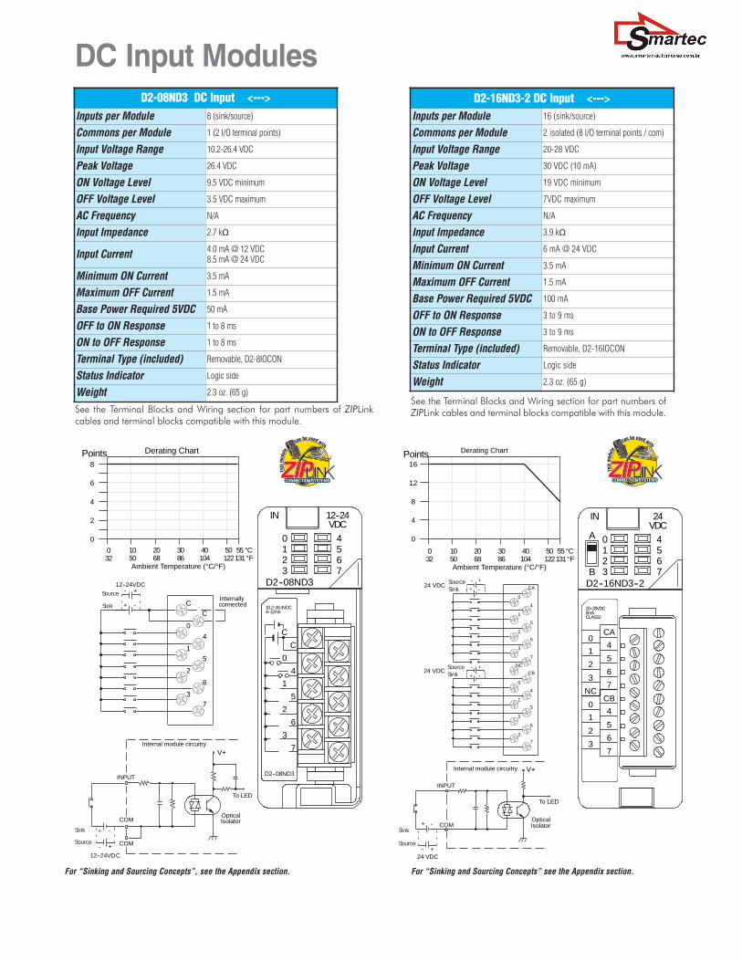
See the Terminal Blocks and Wiring section for part numbers ofZIPLink cables and terminal blocks compatible with this module.
See the Terminal Blocks and Wiring section forpart numbers of ZIPLink cables and terminalblocks compatible with this module.
D2-32ND3 DC Input <--->Inputs per Module 32 (sink/source)
Commons per Module 4 isolated (8 I/O terminal points / com)
Input Voltage Range 20-28 VDC
Peak Voltage 30 VDC
ON Voltage Level 19 VDC minimum
OFF Voltage Level 7 VDC maximum
AC Frequency N/A
Input Impedance 4.8 k�
Input Current 8.0 mA @ 24 VDC
Minimum ON Current 3.5 mA
Maximum OFF Current 1.5 mA
Base Power Required 5VDC 25 mA
OFF to ON Response 3 to 9 ms
ON to OFF Response 3 to 9 ms
Terminal Type (not included) Removable 40-pin Connector1
Status Indicator Module Activity LED
Weight 2.1 oz. (60 g)1 Connector sold separately.See Terminal Blocks and Wiring for wiring options.
D2-32ND3-2 DC Input <--->Inputs per Module 32 (Sink/Source)
Commons per Module 4 isolated (8 I/O terminal points / com)
Input Voltage Range 4.50 to 15.6 VDC min. to max.
Peak Voltage 16 VDC
ON Voltage Level 4 VDC minimum
OFF Voltage Level 2 VDC maximum
AC Frequency N/A
Input Impedance 1.0 k� @ 5-15 VDC
Input Current4 mA @ 5 VDC11 mA @ 12 VDC14 mA @ 15 VDC
Maximum Input Current 16 mA @ 15.6 VDC
Minimum ON Current 3 mA
Maximum OFF Current 0.5 mA
Base Power Required 5VDC 25 mA
OFF to ON Response 3 to 9 ms
ON to OFF Response 3 to 9 ms
Terminal Type (not included) Removable 40-pin connector1
Status Indicator Module activity LED
Weight 2.1 oz (60 g)1 Connector sold separately.See Terminal Blocks and Wiring for wiring options.
For “Sinking and Sourcing Concepts”, see the Appendix section. For “Sinking and Sourcing Concepts” see the Appendix section.
PLC Overview
DL05/06 PLC
DL105 PLC
DL205 PLC
DL305 PLC
DL405 PLC
Field I/O
Software
C-more HMIs
Other HMI
AC Drives
Motors
Steppers/Servos
Motor Controls
ProximitySensors
Photo Sensors
Limit Switches
Encoders
CurrentSensors
Pushbuttons/Lights
Process
Relays/Timers
Comm.
TB’s & Wiring
Power
CircuitProtection
Enclosures
Appendix
Part Index

0
2
4
3
1
0 10 20 30 40 50 55
Ambient Temperature (˚C/˚F )32 50 68 86 104 122131
˚C˚F
Points2A / Pt.
3A / Pt.
4A / Pt.
0V
24V
C
C
C
C
0
1
2
3
24VDC Internallyconnected
L
L
L
L
+
12--24VDC +
C
+24V
0
C1
C2
C3
10.2--26.4VDC50mA--4A
D2--04TD1
OUT 12--24
D2--04TD1
VDC0123
L
L
L
L
C
Common
L
12--24 +
--
+--24VDC
VDC
To LE D
Optical
Isolator
0V
Output
OtherCircuits
Reg
Inductive Load
0.1A 1400 6000.5A 300 1201.0A 140 601.5A 90 352.0A 70 --
Load
80001600
100ms
800540
3.0A400270 -- --
40msCurrent 7msDuration of output in ON state
4.0A 200 -- --
Maximum Number of Switching Cycles per Minute
6.3A
Derating Chart
At 40 mS duration, loads of 3.0A or greater cannot be used.
At 100 mS duration, loads of 2.0A or greater cannot be used.
Find the load current you expect to use and the duration that theoutput is ON. The number at the intersection of the row and col-umn represents the switching cycles per minute. For example, a1A inductive load that is on for 100 ms can be switched on and offa maximum of 60 times per minute. To convert this to duty cyclepercentage use: (duration x cycles)/60. In this example, (60 x .1)/60 = .1, or 10% duty cycle.
DC Output Modules D2-04TD1 DC Output <--->
Outputs per Module 4 (current sinking)
Output Points Consumed 8 points (only first 4 pts. used)
Commons per Module 1 (4 I/O terminal points)
Output Type NMOS FET (open drain)
Operating Voltage 10.2-26.4 VDC
Peak Voltage 40 VDC
ON Voltage Drop 0.72 VDC maximum
AC Frequency N/A
Max Load Current (resistive) 4A/point8A/common
Max Leakage Current 0.1 mA @ 40 VDC
Max Inrush Current 6A for 100 ms, 15A for 10 ms
Minimum Load Current 50 mA
External DC Required 24 VDC @ 20 mA max.
Base Power Required 5VDC 60 mA
OFF to ON Response 1 ms
ON to OFF Response 1 ms
Terminal Type (included) Removable; D2-8IOCON
Status Indicator Logic side
Weight 2.8 oz. (80 g)
Fuses 4 (1 per point)(6.3 A slow blow, non-replaceable)
PLC Overview
DL05/06 PLC
DL105 PLC
DL205 PLC
DL305 PLC
DL405 PLC
Field I/O
Software
C-more HMIs
Other HMI
AC Drives
Motors
Steppers/Servos
Motor Controls
ProximitySensors
Photo Sensors
Limit Switches
Encoders
CurrentSensors
Pushbuttons/Lights
Process
Relays/Timers
Comm.
TB’s & Wiring
Power
CircuitProtection
Enclosures
Appendix
Part Index
OpticalIsolator
L
COM
COM
OUTPUT
12--24VDC
+
5A
Internal module circuitry
C
C
0
1
2
3
4
5
6
7
12--24VDC Internallyconnected
L
L
L
L
L
L
L
L
0
4
8
6
2
0 10 20 30 40 50 55
Ambient Temperature (˚C/˚F )32 50 68 86 104 122131
˚C˚F
Points
+
C
C
0
4
1
5
2
6
3
7
10.2--26.4VDC0.2mA-0.3A
D2--08TD1
OUT 12--24
D2--08TD1
VDC0123
4567
L
L
Derating Chart
DC Output Modules
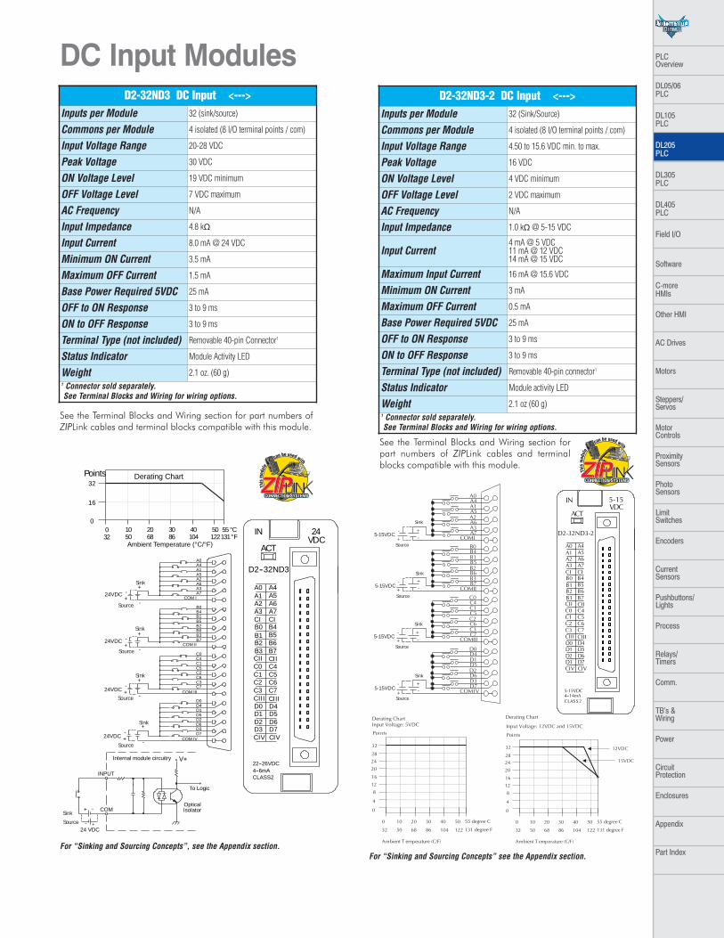
See the Terminal Blocks and Wiring section for part numbers ofZIPLink cables and terminal blocks compatible with this module. See the Terminal Blocks and Wiring section for part numbers of
ZIPLink cables and terminal blocks compatible with this module.
D2-08TD1 DC Output <--->Outputs per Module 8 (current sinking)
Commons per Module 1 (2 I/O terminal points)
Output Type NPN open collector
Operating Voltage 10.2-26.4 VDC
Peak Voltage 40 VDC
ON Voltage Drop 1.5 VDC maximum
AC Frequency N/A
Minimum Load Current 0.5 mA
Max Load Current 0.3A/point; 2.4A/common
Max Leakage Current 0.1 mA @ 40 VDC
Max Inrush Current 1A for 10 ms
Base Power Required 5VDC 100 mA
OFF to ON Response 1ms
ON to OFF Response 1ms
Terminal Type (included) Removable; D2-8IOCON
Status Indicator Logic side
Weight 2.3 oz. (65g)
Fuses 1 per common5A fast blow, non-replaceable
D2-08TD2 DC Output <--->Outputs per Module 8 (current sourcing)
Commons per Module 1
Output Type PNP open collector
Operating Voltage 12 to 24 VDC
Output Voltage 10.8 to 26.4 VDC
Peak Voltage 40 VDC
ON Voltage Drop 1.5 VDC
AC Frequency N/A
Minimum Load Current N/A
Max Load Current 0.3A per point; 2.4A per common
Max Leakage Current 1.0 mA @ 40 VDC
Max Inrush Current 1A for 10 ms
Base Power Required 5VDC 100 mA
OFF to ON Response 1ms
ON to OFF Response 1ms
Terminal Type (included) Removable; D2-8IOCON
Status Indicator Logic side
Weight 2.1 oz. (60g)
Fuses 1 per common5A fast blow, non-replaceable
OpticalIsolator
COM
OUTPUT
12--24+
Internal module circuitry
L
+V
+
24VDC
0 10 20 30 40 50 55
Ambient Temperature (˚C/˚F )32 50 68 86 104 122131
˚C˚F
0
1
1
8
4
2
6Points
0
1
2
3
5
6
7+V
0
1
2
3
C
4
5
6
7
C
4L
L
L
L
L
L
L
L
L
L
L
L
L
L
L
L
COM
Internallyconnected
12--24VDC
24VDC
A
B
10.2--26.4VDC 0.1A
OUT 12--24
D2--16TD1--2
VDC0123
4567
C
4
5
6
7
C
4
5
63
2
1
0
+V
3
2
1
0
7
CLASS2
A
B
+
+
VDC
Derating Chart
DC Output Modules
See the Terminal Blocks and Wiring section for part numbers ofZIPLink cables and terminal blocks compatible with this module.See the Terminal Blocks and Wiring section for part numbers of
ZIPLink cables and terminal blocks compatible with this module.
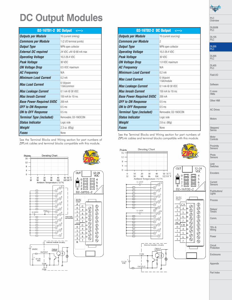
D2-16TD1-2 DC Output <--->Outputs per Module 16 (current sinking)
Commons per Module 1 (2 I/O terminal points)
Output Type NPN open collector
External DC required 24 VDC ±4V @ 80 mA max
Operating Voltage 10.2-26.4 VDC
Peak Voltage 30 VDC
ON Voltage Drop 0.5 VDC maximum
AC Frequency N/A
Minimum Load Current 0.2 mA
Max Load Current 0.1A/point1.6A/common
Max Leakage Current 0.1 mA @ 30 VDC
Max Inrush Current 150 mA for 10 ms
Base Power Required 5VDC 200 mA
OFF to ON Response 0.5 ms
ON to OFF Response 0.5 ms
Terminal Type (included) Removable; D2-16IOCON
Status Indicator Logic side
Weight 2.3 oz. (65g)
Fuses None
D2-16TD2-2 DC Output <--->Outputs per Module 16 (current sourcing)
Commons per Module 2
Output Type NPN open collector
Operating Voltage 10.2-26.4 VDC
Peak Voltage 30 VDC
ON Voltage Drop 1.0 VDC maximum
AC Frequency N/A
Minimum Load Current 0.2 mA
Max Load Current 0.1A/point1.6A/module
Max Leakage Current 0.1 mA @ 30 VDC
Max Inrush Current 150 mA for 10 ms
Base Power Required 5VDC 200 mA
OFF to ON Response 0.5 ms
ON to OFF Response 0.5 ms
Terminal Type (included) Removable; D2-16IOCON
Status Indicator Logic side
Weight 2.8 oz. (80g)
Fuses None
PLC Overview
DL05/06 PLC
DL105 PLC
DL205 PLC
DL305 PLC
DL405 PLC
Field I/O
Software
C-more HMIs
Other HMI
AC Drives
Motors
Steppers/Servos
Motor Controls
ProximitySensors
Photo Sensors
Limit Switches
Encoders
CurrentSensors
Pushbuttons/Lights
Process
Relays/Timers
Comm.
TB’s & Wiring
Power
CircuitProtection
Enclosures
Appendix
Part Index
DC Output Modules
See the Terminal Blocks and Wiring section for part numbers ofZIPLink cables and terminal blocks compatible with this module.
See the Terminal Blocks and Wiring section for partnumbers of ZIPLink cables and terminal blockscompatible with this module.
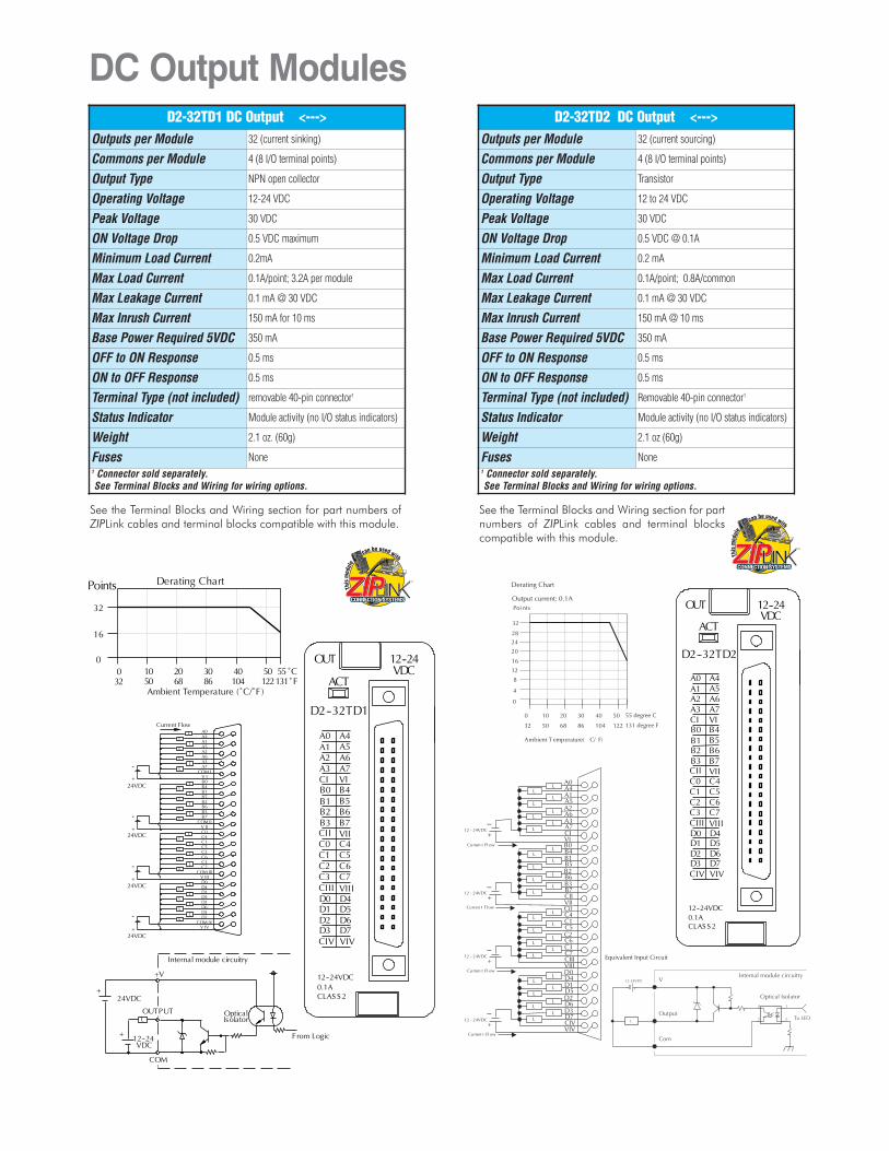
D2-32TD1 DC Output <--->Outputs per Module 32 (current sinking)
Commons per Module 4 (8 I/O terminal points)
Output Type NPN open collector
Operating Voltage 12-24 VDC
Peak Voltage 30 VDC
ON Voltage Drop 0.5 VDC maximum
Minimum Load Current 0.2mA
Max Load Current 0.1A/point; 3.2A per module
Max Leakage Current 0.1 mA @ 30 VDC
Max Inrush Current 150 mA for 10 ms
Base Power Required 5VDC 350 mA
OFF to ON Response 0.5 ms
ON to OFF Response 0.5 ms
Terminal Type (not included) removable 40-pin connector1
Status Indicator Module activity (no I/O status indicators)
Weight 2.1 oz. (60g)
Fuses None1 Connector sold separately.See Terminal Blocks and Wiring for wiring options.
D2-32TD2 DC Output <--->Outputs per Module 32 (current sourcing)
Commons per Module 4 (8 I/O terminal points)
Output Type Transistor
Operating Voltage 12 to 24 VDC
Peak Voltage 30 VDC
ON Voltage Drop 0.5 VDC @ 0.1A
Minimum Load Current 0.2 mA
Max Load Current 0.1A/point; 0.8A/common
Max Leakage Current 0.1 mA @ 30 VDC
Max Inrush Current 150 mA @ 10 ms
Base Power Required 5VDC 350 mA
OFF to ON Response 0.5 ms
ON to OFF Response 0.5 ms
Terminal Type (not included) Removable 40-pin connector1
Status Indicator Module activity (no I/O status indicators)
Weight 2.1 oz (60g)
Fuses None 1 Connector sold separately.See Terminal Blocks and Wiring for wiring options.
NC
NC
C0
C1
C2
C3
0
1
2
3
L
L
L
L
5--30 VDCNC
NCC0
0
C1
1
C2
2
C3
3
5-240VAC4A50/60Hz
D2--04TRS
OUT RELAY
D2--04TRS
0123
L
5--30VDC10mA--4A
L
L
L
5--240 VAC
0
2
4
3
1
0 10 20 30 40 50 55
Ambient Temperature (˚C/˚F )32 50 68 86 104 122 131
˚ C˚ F
Points2A /Pt.
3A /Pt.
4A /Pt.
COM
OUTPUT
To LE D
Internal module circuitry
6.3A5--240 VAC
L
5--30 VDC
Derating Chart
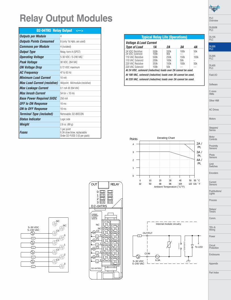
Typical Relay Life (Operations)Voltage &Load CurrentType of Load 1A 2A 3A 4A24 VDC Resistive 500k 200k 100k 50k24 VDC Solenoid 100k 40k –– –110 VAC Resistive 500k 250k 150k 100k110 VAC Solenoid 200k 100k 50k –220 VAC Resistive 350k 150k 100k 50k220 VAC Solenoid 100k 50k –– ––At 24 VDC, solenoid (inductive) loads over 2A cannot be used.
At 100 VAC, solenoid (inductive) loads over 3A cannot be used.
At 220 VAC, solenoid (inductive) loads over 2A cannot be used.
Relay Output Modules D2-04TRS Relay Output <--->
Outputs per Module 4
Outputs Points Consumed 8 (only 1st 4pts. are used)
Commons per Module 4 (isolated)
Output Type Relay, form A (SPST)
Operating Voltage 5-30 VDC / 5-240 VAC
Peak Voltage 30 VDC, 264 VAC
ON Voltage Drop 0.72 VDC maximum
AC Frequency 47 to 63 Hz
Minimum Load Current 10 mA
Max Load Current (resistive) 4A/point; 8A/module (resistive)
Max Leakage Current 0.1 mA @ 264 VAC
Max Inrush Current 5A for < 10 ms
Base Power Required 5VDC 250 mA
OFF to ON Response 10 ms
ON to OFF Response 10 ms
Terminal Type (included) Removable; D2-8IOCON
Status Indicator Logic side
Weight 2.8 oz. (80 g)
Fuses1 per point6.3A slow blow, replaceableOrder D2-FUSE-3 (5 per pack)
PLC Overview
DL05/06 PLC
DL105 PLC
DL205 PLC
DL305 PLC
DL405 PLC
Field I/O
Software
C-more HMIs
Other HMI
AC Drives
Motors
Steppers/Servos
Motor Controls
ProximitySensors
Photo Sensors
Limit Switches
Encoders
CurrentSensors
Pushbuttons/Lights
Process
Relays/Timers
Comm.
TB’s & Wiring
Power
CircuitProtection
Enclosures
Appendix
Part Index
0
4
8
6
2
Points
0.5A / Pt.
COM
OUTPUT
To LE D
Internal module circuitry
6.3A5--240 VAC
L
5--30 VDC
1A / Pt.
C
C
0
1
2
3
4
5
6
7
Internallyconnected
L
L
L
L
L
L
L
L
5--240 VAC5--30 VDC
0 10 20 30 40 50 55
Ambient Temperature (˚C/˚F )32 50 68 86 104 122131
˚C˚F
C
C
0
4
1
5
2
6
3
7
5-240VAC1A50/60Hz
D2--08TR
OUT RELAY
D2--08TR
0123
4567
L
L
5--30VDC5mA--1A
Derating Chart
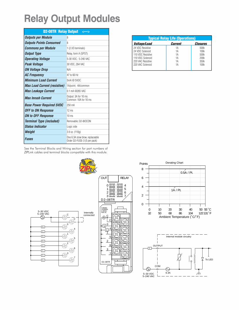
Typical Relay Life (Operations)Voltage/Load Current Closures24 VDC Resistive 1A 500k24 VDC Solenoid 1A 100k110 VDC Resistive 1A 500k110 VDC Solenoid 1A 200k220 VAC Resistive 1A 350k220 VAC Solenoid 1A 100k
Relay Output Modules
See the Terminal Blocks and Wiring section for part numbers ofZIPLink cables and terminal blocks compatible with this module.
D2-08TR Relay Output <--->Outputs per Module 8
Outputs Points Consumed 8
Commons per Module 1 (2 I/O terminals)
Output Type Relay, form A (SPST)
Operating Voltage 5-30 VDC; 5-240 VAC
Peak Voltage 30 VDC, 264 VAC
ON Voltage Drop N/A
AC Frequency 47 to 60 Hz
Minimum Load Current 5mA @ 5VDC
Max Load Current (resistive) 1A/point; 4A/common
Max Leakage Current 0.1 mA @265 VAC
Max Inrush Current Output: 3A for 10 msCommon: 10A for 10 ms
Base Power Required 5VDC 250 mA
OFF to ON Response 12 ms
ON to OFF Response 10 ms
Terminal Type (included) Removable; D2-8IOCON
Status Indicator Logic side
Weight 3.9 oz. (110g)
Fuses One 6.3A slow blow, replaceableOrder D2-FUSE-3 (5 per pack)
12--250VAC7A50/60Hz
OUT RELAY
F2--08TRS
0123
45
NO 0
C0
NC 0
C3
NO 3
C5
NO 5
NC 7
C7NO 6
C6
NC 6
NO 4
C4
NO 2
C2
NO 1
C1
NO7
12--28VDC10ma--7A
67
L
Common
NO
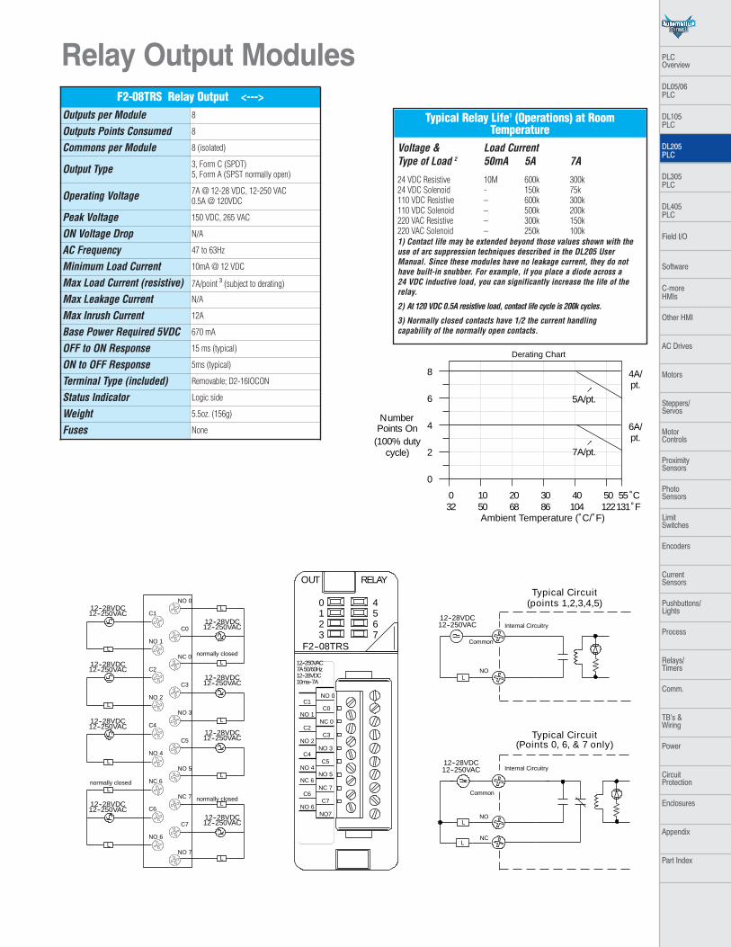
Typical Circuit
L
Common
NO
NCL
12--250VAC12--28VDC
12--250VAC12--28VDC
Internal Circuitry
Internal Circuitry
Typical Circuit(Points 0, 6, & 7 only)
(points 1,2,3,4,5)
0
4
8
6
2
5A/pt.
0 10 20 30 40 50 55
Ambient Temperature (˚C/˚F )32 50 68 86 104 122131
˚C˚F
4A/pt.
7A/pt.
6A/pt.
NumberPoints On
(100% dutycycle)
C6
C7
NC 6
NC 7
NO 4
NO 5
C4
C5
NO 2
NO 3
C2
C3
NO 1
NC 0
C1
C0
NO 0
NO 6
NO 7
L
12--28VDC12--250VAC
L
12--28VDC12--250VAC
L
12--28VDC12--250VAC
L
12--28VDC12--250VAC
L
12--28VDC12--250VAC
Lnormally closed
L
12--28VDC12--250VAC
Lnormally closed
L
12--28VDC12--250VAC
L
12--28VDC12--250VAC
L
normally closed
Derating Chart
Typical Relay Life1 (Operations) at RoomTemperature
Voltage & Load CurrentType of Load 2 50mA 5A 7A
24 VDC Resistive 10M 600k 300k24 VDC Solenoid - 150k 75k110 VDC Resistive – 600k 300k110 VDC Solenoid – 500k 200k220 VAC Resistive – 300k 150k220 VAC Solenoid – 250k 100k1) Contact life may be extended beyond those values shown with theuse of arc suppression techniques described in the DL205 UserManual. Since these modules have no leakage current, they do nothave built-in snubber. For example, if you place a diode across a 24 VDC inductive load, you can significantly increase the life of therelay.
2) At 120 VDC 0.5A resistive load, contact life cycle is 200k cycles.
3) Normally closed contacts have 1/2 the current handling capability of the normally open contacts.
Relay Output Modules F2-08TRS Relay Output <--->
Outputs per Module 8
Outputs Points Consumed 8
Commons per Module 8 (isolated)
Output Type 3, Form C (SPDT)5, Form A (SPST normally open)
Operating Voltage 7A @ 12-28 VDC, 12-250 VAC0.5A @ 120VDC
Peak Voltage 150 VDC, 265 VAC
ON Voltage Drop N/A
AC Frequency 47 to 63Hz
Minimum Load Current 10mA @ 12 VDC
Max Load Current (resistive) 7A/point 3 (subject to derating)
Max Leakage Current N/A
Max Inrush Current 12A
Base Power Required 5VDC 670 mA
OFF to ON Response 15 ms (typical)
ON to OFF Response 5ms (typical)
Terminal Type (included) Removable; D2-16IOCON
Status Indicator Logic side
Weight 5.5oz. (156g)
Fuses None
PLC Overview
DL05/06 PLC
DL105 PLC
DL205 PLC
DL305 PLC
DL405 PLC
Field I/O
Software
C-more HMIs
Other HMI
AC Drives
Motors
Steppers/Servos
Motor Controls
ProximitySensors
Photo Sensors
Limit Switches
Encoders
CurrentSensors
Pushbuttons/Lights
Process
Relays/Timers
Comm.
TB’s & Wiring
Power
CircuitProtection
Enclosures
Appendix
Part Index
OUT RELAY
F2--08TR
0123
45
12--250VAC10A50/60Hz12--28VDC10ma--10A
67
L
Common
NO
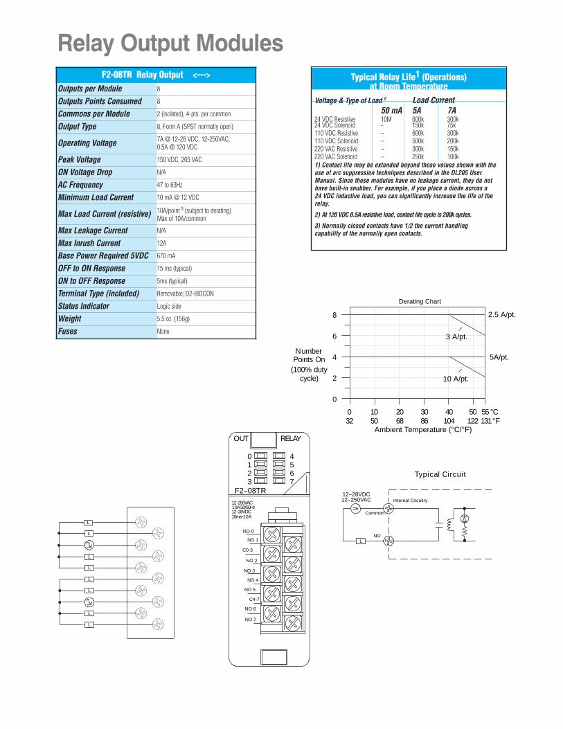
Typical Circuit
12--250VAC12--28VDC
Internal Circuitry
0
4
8
6
2
0 10 20 30 40 50 55
Ambient Temperature (°C/°F )32 50 68 86 104 122 131
°C°F
10 A/pt.
NumberPoints On
(100% dutycycle)
NO 4
NO 5
C4-7
NO 2
NO 3
NO 1
C0-3
NO 0
NO 6
NO 7
Derating Chart
L
L
L
L
L
L
L
L
3 A/pt.
2.5 A/pt.
5A/pt.
Typical Relay Life1 (Operations) at Room Temperature
Voltage & Type of Load 2 Load Current50 mA 5A 7A
24 VDC Resistive 10M 600k 300k24 VDC Solenoid - 150k 75k110 VDC Resistive – 600k 300k110 VDC Solenoid – 500k 200k220 VAC Resistive – 300k 150k220 VAC Solenoid – 250k 100k1) Contact life may be extended beyond those values shown with theuse of arc suppression techniques described in the DL205 UserManual. Since these modules have no leakage current, they do nothave built-in snubber. For example, if you place a diode across a 24 VDC inductive load, you can significantly increase the life of therelay.
2) At 120 VDC 0.5A resistive load, contact life cycle is 200k cycles.
3) Normally closed contacts have 1/2 the current handling capability of the normally open contacts.
Relay Output ModulesF2-08TR Relay Output <--->
Outputs per Module 8
Outputs Points Consumed 8
Commons per Module 2 (isolated), 4-pts. per common
Output Type 8, Form A (SPST normally open)
Operating Voltage 7A @ 12-28 VDC, 12-250VAC;0.5A @ 120 VDC
Peak Voltage 150 VDC, 265 VAC
ON Voltage Drop N/A
AC Frequency 47 to 63Hz
Minimum Load Current 10 mA @ 12 VDC
Max Load Current (resistive) 10A/point 3 (subject to derating)Max of 10A/common
Max Leakage Current N/A
Max Inrush Current 12A
Base Power Required 5VDC 670 mA
OFF to ON Response 15 ms (typical)
ON to OFF Response 5ms (typical)
Terminal Type (included) Removable; D2-8IOCON
Status Indicator Logic side
Weight 5.5 oz. (156g)
Fuses None
Relay Output Modules
A
B
5--240VAC1.5A50/60Hz
D2--12TR
OUT RELAY
D2--12TR
0123
45
CA
4
5
CB
4
5
3
2
1
0
3
2
1
0
5--30VDC
0
1
4
8
2
Points
COM
OUTPUT
To LE D
Internal module circuitry
4A
5--240 VAC
L
5--30 VDC
0.5A / Pt.
0 10 20 30 40 50 55
Ambient Temperature (˚C/˚F )32 50 68 86 104 122131
˚C˚F
1.5A / Pt.
0.75A / Pt.
5mA--1.5A
0
1
2
3
5
NC
NC
NC
0
1
2
3
CB
4
5
NC
NC
CA
4L
L
L
L
L
L
L
L
L
L
L
L
5--240 VAC5--30 VDC
5--240 VAC5--30 VDC
1.25A / Pt.
Derating Chart
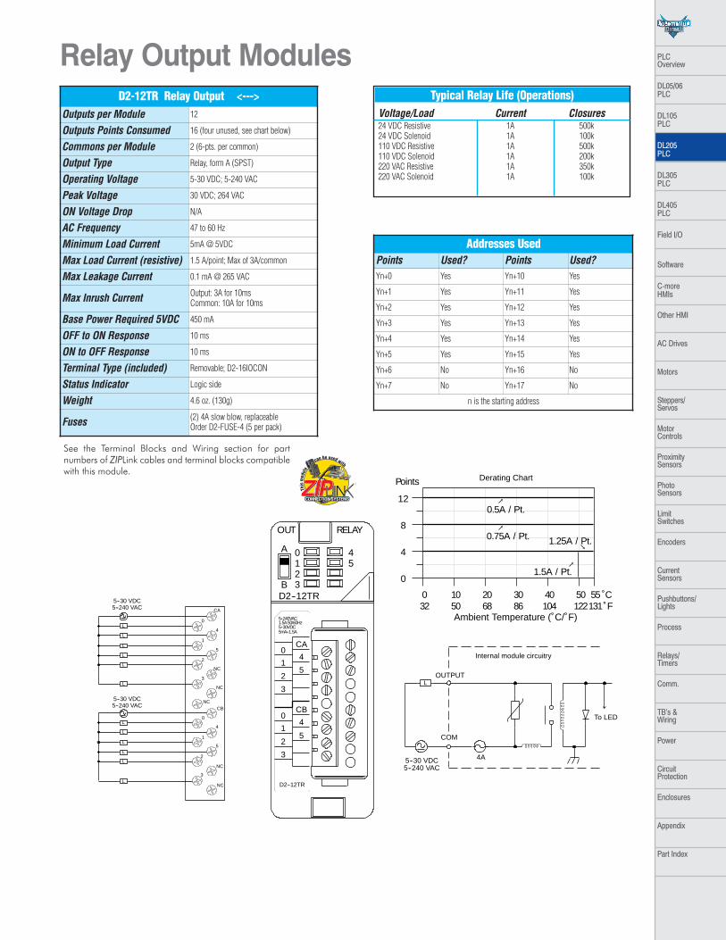
Typical Relay Life (Operations)Voltage/Load Current Closures24 VDC Resistive 1A 500k24 VDC Solenoid 1A 100k110 VDC Resistive 1A 500k110 VDC Solenoid 1A 200k220 VAC Resistive 1A 350k220 VAC Solenoid 1A 100k
See the Terminal Blocks and Wiring section for partnumbers of ZIPLink cables and terminal blocks compatiblewith this module.
Addresses UsedPoints Used? Points Used?Yn+0 Yes Yn+10 Yes
Yn+1 Yes Yn+11 Yes
Yn+2 Yes Yn+12 Yes
Yn+3 Yes Yn+13 Yes
Yn+4 Yes Yn+14 Yes
Yn+5 Yes Yn+15 Yes
Yn+6 No Yn+16 No
Yn+7 No Yn+17 No
n is the starting address
D2-12TR Relay Output <--->Outputs per Module 12
Outputs Points Consumed 16 (four unused, see chart below)
Commons per Module 2 (6-pts. per common)
Output Type Relay, form A (SPST)
Operating Voltage 5-30 VDC; 5-240 VAC
Peak Voltage 30 VDC; 264 VAC
ON Voltage Drop N/A
AC Frequency 47 to 60 Hz
Minimum Load Current 5mA @ 5VDC
Max Load Current (resistive) 1.5 A/point; Max of 3A/common
Max Leakage Current 0.1 mA @ 265 VAC
Max Inrush Current Output: 3A for 10msCommon: 10A for 10ms
Base Power Required 5VDC 450 mA
OFF to ON Response 10 ms
ON to OFF Response 10 ms
Terminal Type (included) Removable; D2-16IOCON
Status Indicator Logic side
Weight 4.6 oz. (130g)
Fuses (2) 4A slow blow, replaceableOrder D2-FUSE-4 (5 per pack)
PLC Overview
DL05/06 PLC
DL105 PLC
DL205 PLC
DL305 PLC
DL405 PLC
Field I/O
Software
C-more HMIs
Other HMI
AC Drives
Motors
Steppers/Servos
Motor Controls
ProximitySensors
Photo Sensors
Limit Switches
Encoders
CurrentSensors
Pushbuttons/Lights
Process
Relays/Timers
Comm.
TB’s & Wiring
Power
CircuitProtection
Enclosures
Appendix
Part Index
CA
0
0
1
1
2
2
3
3
CB
D2--08CDR20--28VDC
8mA
L
IN/ 24VDC
D2--08CDR
RELAY0123
0123
OUTA B
0
2
4
3
1
PointsOut-puts
1A / Pt.
Derating Chart
COM
OUTPUT
To LE D
Internal module circuitry
6.3A
5--240 VAC
L
5--30 VDC
CA
O
0
1
2
3
1
2
3
CB
L
5--240 VAC5--30 VDC
0 10 20 30 40 50 55
Ambient Temperature (°C/°F )32 50 68 86 104 122131
°C°F
L
L
L
5--240VAC1A50/60Hz5--30VDC5mA--1A
Inputs5mA /
Pt.
OpticalCOM Isolator
INPUT
24VDC
V+
To LE D
Internal module circuitry
+L
L
L
24VDC
+ --Sink
Source
Sink
Source
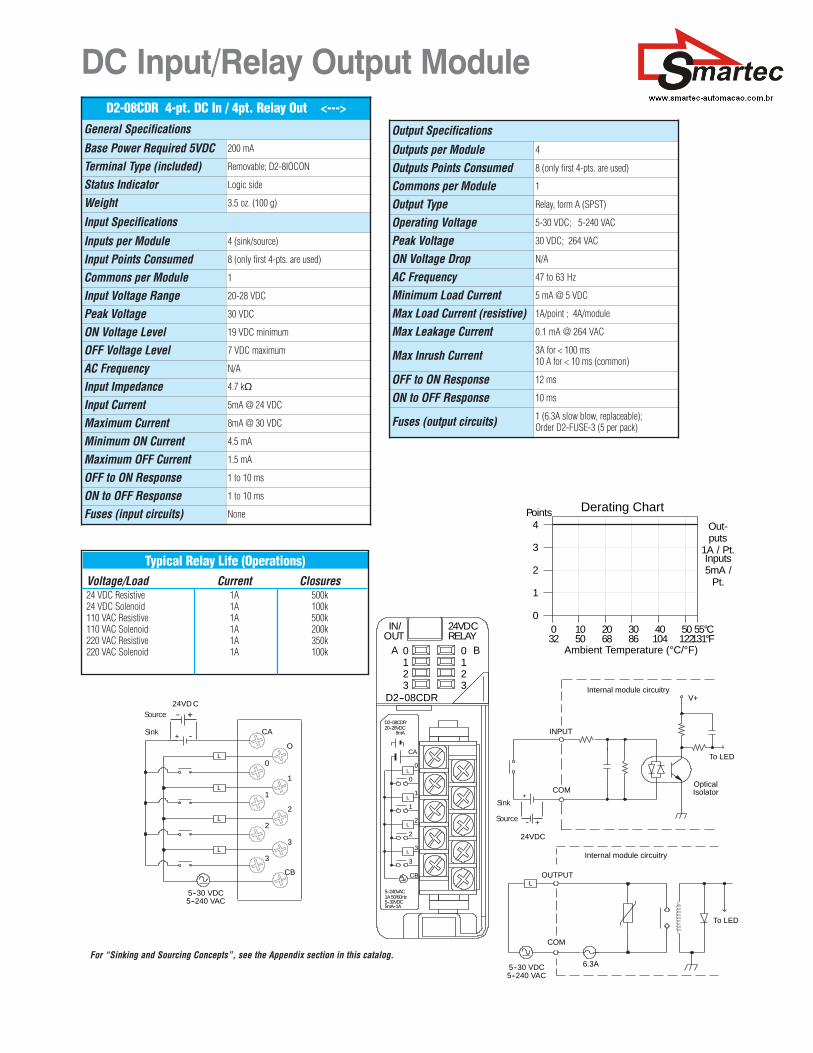
Typical Relay Life (Operations)Voltage/Load Current Closures24 VDC Resistive 1A 500k24 VDC Solenoid 1A 100k110 VAC Resistive 1A 500k110 VAC Solenoid 1A 200k220 VAC Resistive 1A 350k220 VAC Solenoid 1A 100k
DC Input/Relay Output ModuleD2-08CDR 4-pt. DC In / 4pt. Relay Out <--->
General Specifications
Base Power Required 5VDC 200 mA
Terminal Type (included) Removable; D2-8IOCON
Status Indicator Logic side
Weight 3.5 oz. (100 g)
Input Specifications
Inputs per Module 4 (sink/source)
Input Points Consumed 8 (only first 4-pts. are used)
Commons per Module 1
Input Voltage Range 20-28 VDC
Peak Voltage 30 VDC
ON Voltage Level 19 VDC minimum
OFF Voltage Level 7 VDC maximum
AC Frequency N/A
Input Impedance 4.7 k�
Input Current 5mA @ 24 VDC
Maximum Current 8mA @ 30 VDC
Minimum ON Current 4.5 mA
Maximum OFF Current 1.5 mA
OFF to ON Response 1 to 10 ms
ON to OFF Response 1 to 10 ms
Fuses (input circuits) None
Output Specifications
Outputs per Module 4
Outputs Points Consumed 8 (only first 4-pts. are used)
Commons per Module 1
Output Type Relay, form A (SPST)
Operating Voltage 5-30 VDC; 5-240 VAC
Peak Voltage 30 VDC; 264 VAC
ON Voltage Drop N/A
AC Frequency 47 to 63 Hz
Minimum Load Current 5 mA @ 5 VDC
Max Load Current (resistive) 1A/point ; 4A/module
Max Leakage Current 0.1 mA @ 264 VAC
Max Inrush Current 3A for < 100 ms10 A for < 10 ms (common)
OFF to ON Response 12 ms
ON to OFF Response 10 ms
Fuses (output circuits) 1 (6.3A slow blow, replaceable);Order D2-FUSE-3 (5 per pack)
For “Sinking and Sourcing Concepts”, see the Appendix section in this catalog.