Embed Size (px)
Citation preview

8/12/2019 DB DeltaCap B32303_B32304 July.17th.2010-Version 3 (1)
http://slidepdf.com/reader/full/db-deltacap-b32303b32304-july17th2010-version-3-1 1/14
Film Capacitors – Power Factor Correction
DeltaCap MKD capacitors
Series/Type: B32303A/B32304AOrdering code: B32303A****A***/B32304A****A***
Date: July. 2010
Version: 3
© EPCOS AG 2010. Reproduction, publication and dissemination of this publication, enclosures hereto and the informationcontained therein without EPCOS' prior express consent is prohibited.
Content of header bars 1 and 2 of data sheet will be automatically entered in headers and footers! Please fill in thetable and then change the color to "white". This ensures that the table disappears (invisible) for the customer PDF.Don't change formatting when entering or pasting text in the table and don't add any cell or line in and to it!
Identification/Classification 1(header 1 + top left bar):
Film Capacitors – Power Factor Correction
Identification/Classification 2(header 2 + bottom left header bar):
DeltaCap MKD capacitors
Ordering code: (top right header bar) B32303A****A***/B32304A****A***
Series/Type: (top right header bar) B32303A/B32304A
Preliminary data (optional):(if necessary)
Department: NG FK PC PM PFC
Date: July. 2010
Version: 3

8/12/2019 DB DeltaCap B32303_B32304 July.17th.2010-Version 3 (1)
http://slidepdf.com/reader/full/db-deltacap-b32303b32304-july17th2010-version-3-1 2/14
Film Capacitors – Power Factor Correction B32303A****A***/B32304A****A***
DeltaCap MKD capacitors B32303A/B32304A
NG FK PC PM PFC July. 2010
Please read Cautions and warnings and Page 2 of 14Important notes at the end of this document.
Construction
Dielectric: Polypropylene filmResin filling: Non-PCB,biodegradable soft resin
Stacked winding
Extruded round aluminium can with stud
B32304 provided with integrated discharge resistors
Features
Three-phase
Provided with discharge resistors
Double safety system: overpressure disconnector,
self healing technology
Naturally air cooled (or forced air cooling)
Indoor mounting
Typical applications
For Power Factor Correction
Terminals
Screw terminals
Mounting Threaded stud at bottom of can
(max. torque for M12 = 10 Nm)
8/12/2019 DB DeltaCap B32303_B32304 July.17th.2010-Version 3 (1)
http://slidepdf.com/reader/full/db-deltacap-b32303b32304-july17th2010-version-3-1 3/14
Film Capacitors – Power Factor Correction B32303A****A***/B32304A****A***
DeltaCap MKD capacitors B32303A/B32304A
NG FK PC PM PFC July. 2010
Please read Cautions and warnings and Page 3 of 14Important notes at the end of this document.
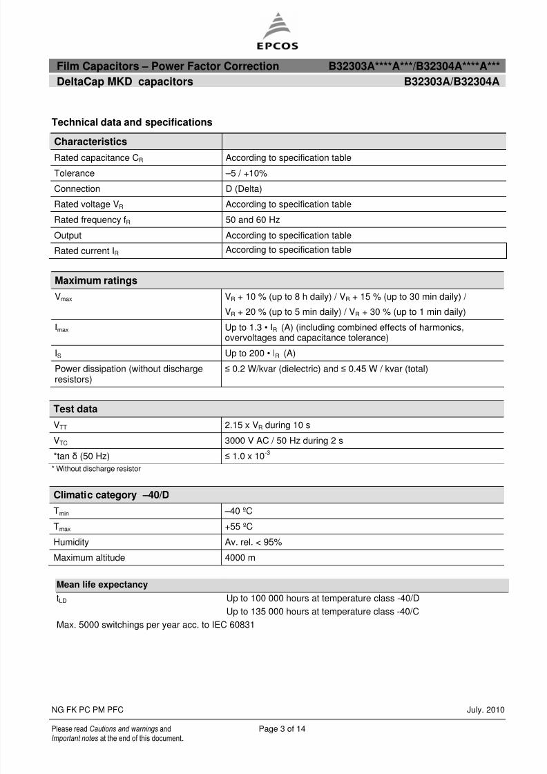
Technical data and specifications
Maximum ratings
Vmax VR + 10 % (up to 8 h daily) / VR + 15 % (up to 30 min daily) /
VR + 20 % (up to 5 min daily) / VR + 30 % (up to 1 min daily)
Imax Up to 1.3 • IR (A) (including combined effects of harmonics,overvoltages and capacitance tolerance)
IS Up to 200 • IR (A)
Power dissipation (without dischargeresistors)
≤ 0.2 W/kvar (dielectric) and ≤ 0.45 W / kvar (total)
Test data
VTT 2.15 x VR during 10 s
VTC 3000 V AC / 50 Hz during 2 s
*tan δ (50 Hz) ≤ 1.0 x 10⁻³
* Without discharge resistor
Climatic category –40/D
Tmin –40 ºC
Tmax +55 ºC
Humidity Av. rel. < 95%
Maximum altitude 4000 m
Mean life expectancy
tLD Up to 100 000 hours at temperature class -40/D
Up to 135 000 hours at temperature class -40/C
Max. 5000 switchings per year acc. to IEC 60831
Characteristics
Rated capacitance CR According to specification table
Tolerance –5 / +10%
Connection D (Delta)
Rated voltage VR According to specification table
Rated frequency fR 50 and 60 Hz
Output According to specification table
Rated current IR According to specification table
8/12/2019 DB DeltaCap B32303_B32304 July.17th.2010-Version 3 (1)
http://slidepdf.com/reader/full/db-deltacap-b32303b32304-july17th2010-version-3-1 4/14
Film Capacitors – Power Factor Correction B32303A****A***/B32304A****A***
DeltaCap MKD capacitors B32303A/B32304A
NG FK PC PM PFC July. 2010
Please read Cautions and warnings and Page 4 of 14Important notes at the end of this document.
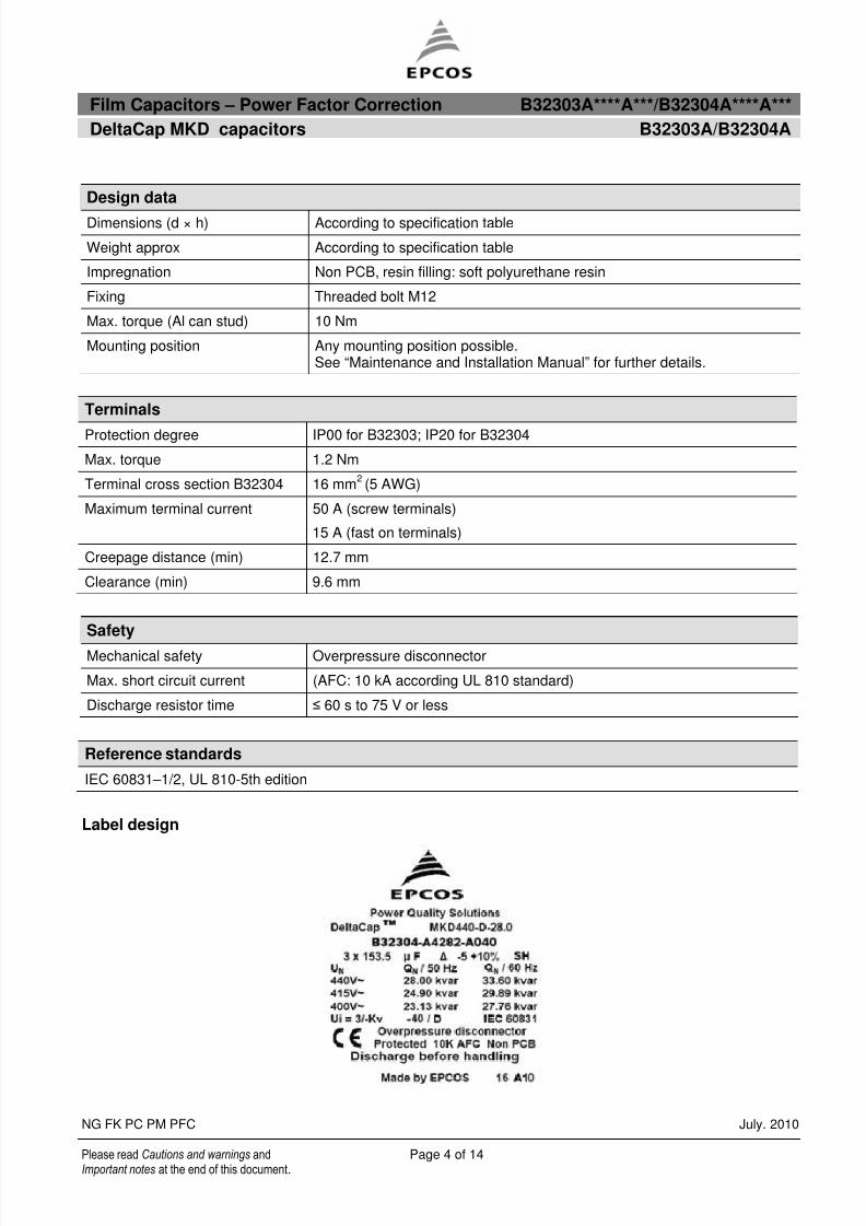
Terminals
Protection degree IP00 for B32303; IP20 for B32304
Max. torque 1.2 Nm
Terminal cross section B32304 16 mm2(5 AWG)
Maximum terminal current 50 A (screw terminals)
15 A (fast on terminals)
Creepage distance (min) 12.7 mm
Clearance (min) 9.6 mm
Safety
Mechanical safety Overpressure disconnector
Max. short circuit current (AFC: 10 kA according UL 810 standard)
Discharge resistor time ≤ 60 s to 75 V or less
Reference standards
IEC 60831–1/2, UL 810-5th edition
Label design
Design data
Dimensions (d × h) According to specification table
Weight approx According to specification table
Impregnation Non PCB, resin filling: soft polyurethane resin
Fixing Threaded bolt M12
Max. torque (Al can stud) 10 Nm
Mounting position Any mounting position possible.See “Maintenance and Installation Manual” for further details.

8/12/2019 DB DeltaCap B32303_B32304 July.17th.2010-Version 3 (1)
http://slidepdf.com/reader/full/db-deltacap-b32303b32304-july17th2010-version-3-1 5/14
Film Capacitors – Power Factor Correction B32303A****A***/B32304A****A***
DeltaCap MKD capacitors B32303A/B32304A
NG FK PC PM PFC July. 2010
Please read Cautions and warnings and Page 5 of 14Important notes at the end of this document.
Dimensional drawings
Series B32303
Torque=10Nm
Toothed washer J12 DIN6797
Hex nut BM 12 DIN439
Marking

8/12/2019 DB DeltaCap B32303_B32304 July.17th.2010-Version 3 (1)
http://slidepdf.com/reader/full/db-deltacap-b32303b32304-july17th2010-version-3-1 6/14
Film Capacitors – Power Factor Correction B32303A****A***/B32304A****A***
DeltaCap MKD capacitors B32303A/B32304A
NG FK PC PM PFC July. 2010
Please read Cautions and warnings and Page 6 of 14Important notes at the end of this document.
Series B32304

8/12/2019 DB DeltaCap B32303_B32304 July.17th.2010-Version 3 (1)
http://slidepdf.com/reader/full/db-deltacap-b32303b32304-july17th2010-version-3-1 7/14
Film Capacitors – Power Factor Correction B32303A****A***/B32304A****A***
DeltaCap MKD capacitors B32303A/B32304A
NG FK PC PM PFC July. 2010
Please read Cautions and warnings and Page 7 of 14Important notes at the end of this document.
8/12/2019 DB DeltaCap B32303_B32304 July.17th.2010-Version 3 (1)
http://slidepdf.com/reader/full/db-deltacap-b32303b32304-july17th2010-version-3-1 8/14
Film Capacitors – Power Factor Correction B32303A****A***/B32304A****A***
DeltaCap MKD capacitors B32303A/B32304A
NG FK PC PM PFC July. 2010
Please read Cautions and warnings and Page 8 of 14Important notes at the end of this document.
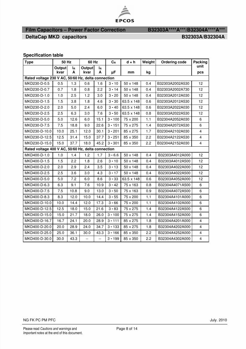
Specification table
Type 50 Hz 60 Hz CR d × h Weight Ordering code
Outputkvar
IR A
Outputkvar
IR A µF mm kg
Packingunit
pcs
Rated voltage 230 V AC, 50/60 Hz, delta connection
MKD230-D-0.5 0.5 1.3 0.6 1.6 3 • 10 50 x 148 0.4 B32303A2002A530 12
MKD230-D-0.7 0.7 1.8 0.8 2.2 3 • 14 50 x 148 0.4 B32303A2002A730 12
MKD230-D-1.0 1.0 2.5 1.2 3.0 3 • 20 50 x 148 0.4 B32303A2012A030 12
MKD230-D-1.5 1.5 3.8 1.8 4.6 3 • 30 63.5 x 148 0.6 B32303A2012A530 12
MKD230-D-2.0 2.0 5.0 2.4 6.0 3 • 40 63.5 x 148 0.6 B32303A2022A030 12
MKD230-D-2.5 2.5 6.3 3.0 7.6 3 • 50 63.5 x 148 0.8 B32303A2022A530 12
MKD230-D-5.0 5.0 12.6 6.0 15.1 3 • 100 75 x 200 1.1 B32304A2052A030 6
MKD230-D-7.5 7.5 18.8 9.0 22.6 3 • 151 75 x 275 1.4 B32304A2072A530 6
MKD230-D-10.0 10.0 25.1 12.0 30.1 3 • 201 85 x 275 1.7 B32304A2102A030 4
MKD230-D-12.5 12.5 31.4 15.0 37.7 3 • 251 85 x 350 2.2 B32304A2122A530 4
MKD230-D-15.0 15.0 37.7 18.0 45.2 3 • 301 85 x 350 2.2 B32304A2152A030 4
Rated voltage 400 V AC, 50/60 Hz, delta connection
MKD400-D-1.0 1.0 1.4 1.2 1.7 3 • 6.6 50 x 148 0.4 B32303A4012A000 12
MKD400-D-1.5 1.5 2.2 1.8 2.6 3 • 10 50 x 148 0.4 B32303A4012A500 12
MKD400-D-2.0 2.0 2.9 2.4 3.5 3 • 13 50 x 148 0.4 B32303A4022A000 12
MKD400-D-2.5 2.5 3.6 3.0 4.3 3 • 17 50 x 148 0.4 B32303A4022A500 12
MKD400-D-5.0 5.0 7.2 6.0 8.6 3 • 33 63.5 x 148 0.6 B32303A4052A000 12
MKD400-D-6.3 6.3 9.1 7.6 10.9 3 • 42 75 x 163 0.8 B32304A4071A500 6
MKD400-D-7.5 7.5 10.8 9.0 13.0 3 • 50 75 x 163 0.9 B32304A4072A500 6
MKD400-D-8.3 8.3 12.0 10.0 14.4 3 • 55 75 x 200 1.1 B32304A4101A000 6
MKD400-D-10.0 10.0 14.4 12.0 17.3 3 • 66 75 x 200 1.1 B32304A4102A000 6
MKD400-D-12.5 12.5 18.0 15.0 21.6 3 • 83 75 x 275 1.4 B32304A4122A500 6
MKD400-D-15.0 15.0 21.7 18.0 26.0 3 • 100 75 x 275 1.4 B32304A4152A000 6
MKD400-D-16.7 16.7 24.1 20.0 28.9 3 • 111 85 x 275 1.8 B32304A4201A000 4
MKD400-D-20.0 20.0 28.9 24.0 34.7 3 • 133 85 x 275 1.8 B32304A4202A000 4
MKD400-D-25.0 25.0 36.1 30.0 43.3 3 • 166 85 x 350 2.2 B32304A4252A000 4
MKD400-D-30.0 30.0 43.3 -- -- 3 • 199 85 x 350 2.2 B32304A4302A000 4
8/12/2019 DB DeltaCap B32303_B32304 July.17th.2010-Version 3 (1)
http://slidepdf.com/reader/full/db-deltacap-b32303b32304-july17th2010-version-3-1 9/14
Film Capacitors – Power Factor Correction B32303A****A***/B32304A****A***
DeltaCap MKD capacitors B32303A/B32304A
NG FK PC PM PFC July. 2010
Please read Cautions and warnings and Page 9 of 14Important notes at the end of this document.
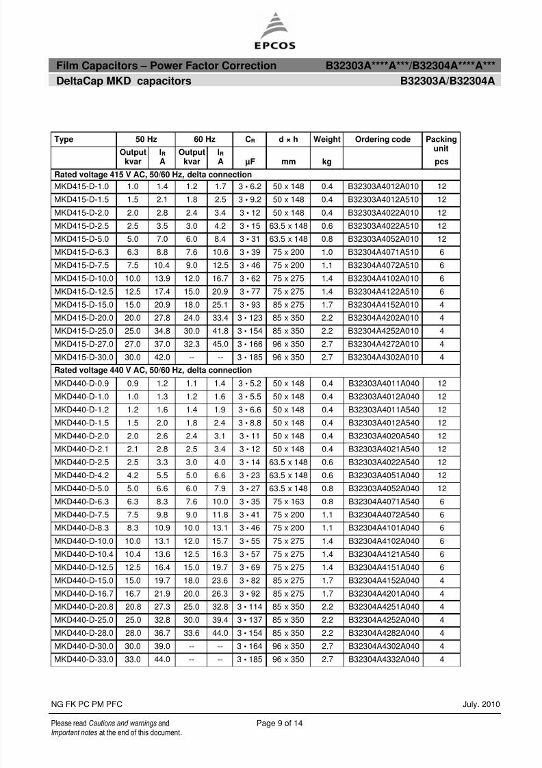
Type 50 Hz 60 Hz CR d × h Weight Ordering code
Outputkvar
IR A
Outputkvar
IR A µF mm kg
Packingunit
pcs
Rated voltage 415 V AC, 50/60 Hz, delta connection
MKD415-D-1.0 1.0 1.4 1.2 1.7 3 • 6.2 50 x 148 0.4 B32303A4012A010 12
MKD415-D-1.5 1.5 2.1 1.8 2.5 3 • 9.2 50 x 148 0.4 B32303A4012A510 12
MKD415-D-2.0 2.0 2.8 2.4 3.4 3 • 12 50 x 148 0.4 B32303A4022A010 12
MKD415-D-2.5 2.5 3.5 3.0 4.2 3 • 15 63.5 x 148 0.6 B32303A4022A510 12
MKD415-D-5.0 5.0 7.0 6.0 8.4 3 • 31 63.5 x 148 0.8 B32303A4052A010 12
MKD415-D-6.3 6.3 8.8 7.6 10.6 3 • 39 75 x 200 1.0 B32304A4071A510 6
MKD415-D-7.5 7.5 10.4 9.0 12.5 3 • 46 75 x 200 1.1 B32304A4072A510 6MKD415-D-10.0 10.0 13.9 12.0 16.7 3 • 62 75 x 275 1.4 B32304A4102A010 6
MKD415-D-12.5 12.5 17.4 15.0 20.9 3 • 77 75 x 275 1.4 B32304A4122A510 6
MKD415-D-15.0 15.0 20.9 18.0 25.1 3 • 93 85 x 275 1.7 B32304A4152A010 4
MKD415-D-20.0 20.0 27.8 24.0 33.4 3 • 123 85 x 350 2.2 B32304A4202A010 4
MKD415-D-25.0 25.0 34.8 30.0 41.8 3 • 154 85 x 350 2.2 B32304A4252A010 4
MKD415-D-27.0 27.0 37.0 32.3 45.0 3 • 166 96 x 350 2.7 B32304A4272A010 4
MKD415-D-30.0 30.0 42.0 -- -- 3 • 185 96 x 350 2.7 B32304A4302A010 4
Rated voltage 440 V AC, 50/60 Hz, delta connection
MKD440-D-0.9 0.9 1.2 1.1 1.4 3 • 5.2 50 x 148 0.4 B32303A4011A040 12
MKD440-D-1.0 1.0 1.3 1.2 1.6 3 • 5.5 50 x 148 0.4 B32303A4012A040 12
MKD440-D-1.2 1.2 1.6 1.4 1.9 3 • 6.6 50 x 148 0.4 B32303A4011A540 12
MKD440-D-1.5 1.5 2.0 1.8 2.4 3 • 8.8 50 x 148 0.4 B32303A4012A540 12
MKD440-D-2.0 2.0 2.6 2.4 3.1 3 • 11 50 x 148 0.4 B32303A4020A540 12
MKD440-D-2.1 2.1 2.8 2.5 3.4 3 • 12 50 x 148 0.4 B32303A4021A540 12
MKD440-D-2.5 2.5 3.3 3.0 4.0 3 • 14 63.5 x 148 0.6 B32303A4022A540 12
MKD440-D-4.2 4.2 5.5 5.0 6.6 3 • 23 63.5 x 148 0.6 B32303A4051A040 12
MKD440-D-5.0 5.0 6.6 6.0 7.9 3 • 27 63.5 x 148 0.8 B32303A4052A040 12
MKD440-D-6.3 6.3 8.3 7.6 10.0 3 • 35 75 x 163 0.8 B32304A4071A540 6
MKD440-D-7.5 7.5 9.8 9.0 11.8 3 • 41 75 x 200 1.1 B32304A4072A540 6
MKD440-D-8.3 8.3 10.9 10.0 13.1 3 • 46 75 x 200 1.1 B32304A4101A040 6
MKD440-D-10.0 10.0 13.1 12.0 15.7 3 • 55 75 x 275 1.4 B32304A4102A040 6
MKD440-D-10.4 10.4 13.6 12.5 16.3 3 • 57 75 x 275 1.4 B32304A4121A540 6
MKD440-D-12.5 12.5 16.4 15.0 19.7 3 • 69 75 x 275 1.4 B32304A4151A040 6
MKD440-D-15.0 15.0 19.7 18.0 23.6 3 • 82 85 x 275 1.7 B32304A4152A040 4
MKD440-D-16.7 16.7 21.9 20.0 26.3 3 • 92 85 x 275 1.7 B32304A4201A040 4
MKD440-D-20.8 20.8 27.3 25.0 32.8 3 • 114 85 x 350 2.2 B32304A4251A040 4
MKD440-D-25.0 25.0 32.8 30.0 39.4 3 • 137 85 x 350 2.2 B32304A4252A040 4
MKD440-D-28.0 28.0 36.7 33.6 44.0 3 • 154 85 x 350 2.2 B32304A4282A040 4
MKD440-D-30.0 30.0 39.0 -- -- 3 • 164 96 x 350 2.7 B32304A4302A040 4
MKD440-D-33.0 33.0 44.0 -- -- 3 • 185 96 x 350 2.7 B32304A4332A040 4

8/12/2019 DB DeltaCap B32303_B32304 July.17th.2010-Version 3 (1)
http://slidepdf.com/reader/full/db-deltacap-b32303b32304-july17th2010-version-3-1 10/14
Film Capacitors – Power Factor Correction B32303A****A***/B32304A****A***
DeltaCap MKD capacitors B32303A/B32304A
NG FK PC PM PFC July. 2010
Please read Cautions and warnings and Page 10 of 14Important notes at the end of this document.
Type 50 Hz 60 Hz CR d × h Weight Ordering code
Outputkvar
IR A
Outputkvar
IR A µF mm kg
Packingunit
pcs
Rated voltage 480 V AC, 50/60 Hz, delta connection
MKD480-D-1.5 1.5 1.8 1.8 2.2 3 • 6.9 50 x 148 0.4 B32303A4012A580 12
MKD480-D-2.0 2.0 2.4 2.4 2.9 3 • 9.2 50 x 148 0.4 B32303A4022A080 12
MKD480-D-2.5 2.5 3.0 3.0 3.6 3 • 12 63.5 x 148 0.6 B32303A4022A580 12
MKD480-D-5.0 5.0 6.0 6.0 7.2 3 • 23 75 x 163 0.8 B32304A4052A080 6
MKD480-D-6.3 6.3 7.6 7.6 9.1 3 • 29 75 x 163 0.8 B32304A4071A580 6MKD480-D-7.5 7.5 9.0 9.0 10.8 3 • 35 75 x 200 1.1 B32304A4072A580 6
MKD480-D-8.3 8.3 10.0 10.0 12.0 3 • 38 75 x 200 1.1 B32304A4101A 80 6
MKD480-D-10.4 10.4 12.5 12.5 15.0 3 • 48 75 x 275 1.4 B32304A4121A580 6
MKD480-D-12.5 12.5 15.0 15.0 18.0 3 • 58 75 x 275 1.4 B32304A4151A 80 6
MKD480-D-15.0 15.0 18.0 18.0 21.6 3 • 69 85 x 275 1.7 B32304A4152A080 6
MKD480-D-16.7 16.7 20.1 20.0 24.1 3 • 77 85 x 275 1.8 B32304A4162A780 6
MKD480-D-20.8 20.8 25.0 25.0 30.0 3 • 96 85 x 350 2.2 B32304A4202A080 4
MKD480-D-25.0 25.0 30.1 30.0 36.1 3 • 115 85 x 350 2.2 B32304A4252A080 4
MKD480-D-30.0 30.0 36.0 36.0 43.0 3 • 138 96 x 350 2.7 B32304A4302A080 4
Rated voltage 525 V AC, 50/60 Hz, delta connectionMKD525-D-1.0 1.0 1.1 1.2 1.3 3 • 3.9 50 x 148 0.4 B32303A5012A020 12
MKD525-D-1.5 1.5 1.6 1.8 1.9 3 • 5.8 50 x 148 0.4 B32303A5012A520 12
MKD525-D-2.0 2.0 2.2 2.4 2.6 3 • 7.7 63.5 x 148 0.6 B32303A5022A020 12
MKD525-D-2.5 2.5 2.7 3.0 3.2 3 • 9.6 63.5 x 148 0.6 B32303A5022A520 12
MKD525-D-5.0 5.0 5.5 6.0 6.6 3 • 19 75 x 163 0.8 B32304A5061A020 6
MKD525-D-6.3 6.3 6.9 7.6 8.3 3 • 24 75 x 200 1.0 B32304A5071A520 6
MKD525-D-8.3 8.3 9.1 10.0 10.9 3 • 32 75 x 275 1.4 B32304A5101A020 6
MKD525-D-10.4 10.4 11.4 12.5 13.7 3 • 40 75 x 275 1.4 B32304A5121A520 6
MKD525-D-12.5 12.5 13.7 15.0 16.4 3 • 48 75 x 275 1.4 B32304A5151A020 6
MKD525-D-16.7 16.7 18.4 20.0 22.1 3 • 64 85 x 275 1.8 B32304A5201A020 4
MKD525-D-20.8 20.8 22.9 25.0 27.5 3 • 80 85 x 350 2.2 B32304A5202A020 4
MKD525-D-25.0 25.0 27.5 30.0 33.0 3 • 96 85 x 350 2.2 B32304A5252A020 4
MKD525-D-30.0 30.0 33.0 36.0 39.0 3 • 115 96 x 350 2.7 B32304A5302A020 4

8/12/2019 DB DeltaCap B32303_B32304 July.17th.2010-Version 3 (1)
http://slidepdf.com/reader/full/db-deltacap-b32303b32304-july17th2010-version-3-1 11/14
Film Capacitors – Power Factor Correction B32303A****A***/B32304A****A***
DeltaCap MKD capacitors B32303A/B32304A
NG FK PC PM PFC July. 2010
Please read Cautions and warnings and Page 11 of 14Important notes at the end of this document.
Cautions and warnings
In case of dents of more than 1 mm depth or any other mechanical damage, capacitors must notbe used at all.
This applies also in cases of oil leakages.
To ensure the full functionality of the overpressure disconnector, elastic elements must not behindered and a minimum space of 12 mm has to be kept above each capacitor.
Do not handle the capacitor before it is discharged.
Resonance cases must be avoided by appropriate application design in any case.
Handle capacitors carefully, because they may still be charged even after disconnection due to
faulty discharging devices. Protect the capacitor properly against over current and short circuit.
Failure to follow cautions may result, worst case, in premature failures, bursting and fire.
Discharging
Capacitors must be discharged to a maximum of 10% of rated voltage before they are switched inagain. This prevents an electric impulse discharge in the application, influences the capacitor’sservice life and protects against electric shock. The capacitor must be discharged to 75 V or lesswithin 3 minutes. There must be not any switch, fuse or any other disconnecting device in the circuitbetween the power capacitor and the discharging device. DeltaCap capacitors are delivered withdischarge resistor included; alternatively discharge reactors are available from EPCOS. Dischargeand short circuit capacitor before handling!
Service life expectancy
Electrical components do not have an unlimited service life expectancy; this applies to self-healingcapacitors too. The maximum service life expectancy may vary depending on the application thecapacitor is used in.
Safety
Electrical or mechanical misapplication of capacitors may be hazardous. Personal injury or propertydamage may result from bursting of the capacitor or from expulsion of oil or melted material due tomechanical disruption of the capacitor.
Ensure good, effective grounding for capacitor enclosures. Provide means of disconnecting and insulating a faulty component/bank.
The terminals of capacitors, connected bus bars and cables as well as other devices may also beenergized.
Follow good engineering practice.
Thermal load/over-temperature
After installation of the capacitor it is necessary to verify that maximum hot-spot temperature is notexceeded at extreme service conditions.

8/12/2019 DB DeltaCap B32303_B32304 July.17th.2010-Version 3 (1)
http://slidepdf.com/reader/full/db-deltacap-b32303b32304-july17th2010-version-3-1 12/14
Film Capacitors – Power Factor Correction B32303A****A***/B32304A****A***
DeltaCap MKD capacitors B32303A/B32304A
NG FK PC PM PFC July. 2010
Please read Cautions and warnings and Page 12 of 14Important notes at the end of this document.
Overpressure disconnector
To ensure full functionality of an overpressure disconnector, the following must be observed:1. The elastic elements must not be hindered, i.e.
Connecting lines must be flexible leads (cables).
There must be sufficient space (min. 12 mm) for expansion above the connections. This willenable a longitudinal extension of the can to secure the overpressure disconnector work.
Folding beads must not be retained by clamps.
2. The maximum allowed fault current of 10000 A in accordance with UL 810 standard must beassured by the application.
3. Stress parameters of the capacitor must be within the IEC60831 specification.
Overcurrent and short circuit protection
Use HRC fuses or MCCBs for short circuit protection. Short circuit protection and connectingcables should be selected so that 1.5 times the rated capacitor current can be permanentlyhandled.
HRC fuses do not protect a capacitor against overload – they are only for short circuit protection.
The HRC fuse rating should be 1.6 to 1.8 times rated capacitor current.
Do not use HRC fuses to switch capacitors (risk of arcing).
Use thermal magnetic over current relays for overload protection.
Resonance cases
Resonance cases must be avoided by appropriate application design in any case. Maximum totalRMS capacitor current (incl. fundamental harmonic current) specified in technical data must not beexceeded.
Re-switching vs. phase-opposition
In case of voltage interruption, a sufficient discharge time has to be ensured to avoid phase-opposition and resulting high inrush currents.
Vibration resistance
The resistance to vibration of capacitors corresponds to IEC 68, part 2–6.
Max. test conditions:Test duration 6 h*
Frequency range 1 10 ... 55 Hz*
Displacement amplitude 0.75 mm**corresponding to max. 98.1 m/s or 10 g

8/12/2019 DB DeltaCap B32303_B32304 July.17th.2010-Version 3 (1)
http://slidepdf.com/reader/full/db-deltacap-b32303b32304-july17th2010-version-3-1 13/14
Film Capacitors – Power Factor Correction B32303A****A***/B32304A****A***
DeltaCap MKD capacitors B32303A/B32304A
NG FK PC PM PFC July. 2010
Please read Cautions and warnings and Page 13 of 14Important notes at the end of this document.
These figures apply to the capacitor alone. Because the fixing and the terminals may influence the
vibration properties, it is necessary to check stability when a capacitor is built in and exposed tovibration. Irrespective of this, you are advised not to locate capacitors where vibration amplitudereaches the maximum in strongly vibrating equipment.
Mechanical protection
The capacitor has to be installed in a way that mechanical damages and dents in the aluminum canare avoided.
Grounding
The threaded bottom stud of the capacitor has to be used for grounding. In case grounding is donevia metal chassis that the capacitor is mounted to, the layer of varnish beneath the washer and nutshould be removed. The maximum tightening torque is 10 Nm.
Maintenance
Check tightness of the connections/terminals periodically.
Take current reading twice a year and compare with nominal current. Use a harmonic analyser ortrue effective RMS-meter.
In case of current above the nominal current check your application for modifications.
If a significant increase in the amount of non-linear loads has been detected, then a consultanthas to be called in for a harmonic study.
In case of the presence of harmonics installation of a de-tuned capacitor bank (reactors) must be
considered. Check the discharge resistors/reactors and in case of doubt, check their function:
(1) Power the capacitor up and down.
(2) After ≤ 60 seconds the voltage between the terminals must decline to less than 75 V.
Check the temperature of capacitors directly after operation for a longer period, but make surethat the capacitors have been switched off. In case of excessive temperature of individualcapacitors, it is recommended to replace these capacitors, as this should be an indication for lossfactor increase, which is a sign for reaching end of life.
Storage and operating conditions
Do not use or store capacitors in corrosive atmosphere, especially where chloride gas, sulfide gas,
acid, alkali, salt or the like are present. In dusty environments regular maintenance and cleaningespecially of the terminals is required to avoid conductive path between phases and/or phasesand ground.
Note
For detailed information about PFC capacitors and cautions, refer to the latest version of EPCOS PFCProduct Profile.

8/12/2019 DB DeltaCap B32303_B32304 July.17th.2010-Version 3 (1)
http://slidepdf.com/reader/full/db-deltacap-b32303b32304-july17th2010-version-3-1 14/14