Embed Size (px)
Citation preview
DayDay--22Series Compensation & Series Compensation &
Other FACTS ControllersOther FACTS Controllers
Arindam GhoshArindam GhoshDept. of Electrical EngineeringDept. of Electrical EngineeringIndian Institute of TechnologyIndian Institute of Technology
KanpurKanpur, India, IndiaEE--mail:mail: aghoshaghosh@@iitkiitk.ac.in.ac.in
82
Series Compensation of Series Compensation of Transmission SystemsTransmission Systems
A device that is connected in series with the A device that is connected in series with the transmission line is called a transmission line is called a series series compensatorcompensator. In the analysis given below, . In the analysis given below, we shall investigate the effect of the we shall investigate the effect of the series compensator onseries compensator on
•• the voltage profilethe voltage profile•• the powerthe power--angle characteristicsangle characteristics•• the stability marginthe stability margin•• the damping of power oscillationsthe damping of power oscillations
83
Ideal Series CompensatorIdeal Series Compensator
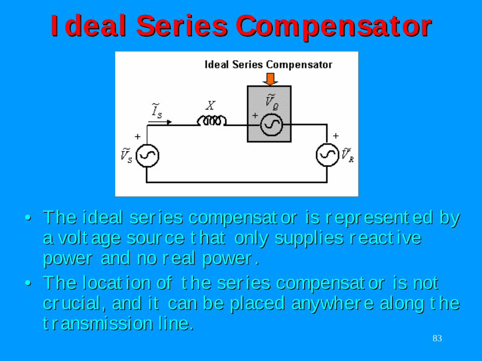
•• The ideal series compensator is represented by The ideal series compensator is represented by a voltage source that only supplies reactive a voltage source that only supplies reactive power and no real power. power and no real power.
•• The location of the series compensator is not The location of the series compensator is not crucial, and it can be placed anywhere along the crucial, and it can be placed anywhere along the transmission line.transmission line.
84
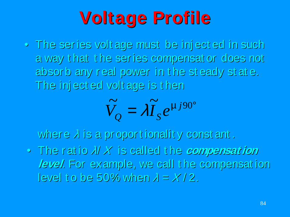
Voltage ProfileVoltage Profile•• The series voltage must be injected in such The series voltage must be injected in such
a way that the series compensator does not a way that the series compensator does not absorb any real power in the steady state. absorb any real power in the steady state. The injected voltage is thenThe injected voltage is then
°= 90~~ jSQ eIV µλ
where where λλ is a proportionality constant. is a proportionality constant. •• The ratio The ratio λλ//XX is called the is called the compensation compensation
levellevel. For example, we call the compensation . For example, we call the compensation level to be 50% when level to be 50% when λλ = = XX /2./2.
85
Voltage ProfileVoltage Profile
( )λδ
µXjVV
jXVVV
I QRSS
−∠=−−
=~~~
~
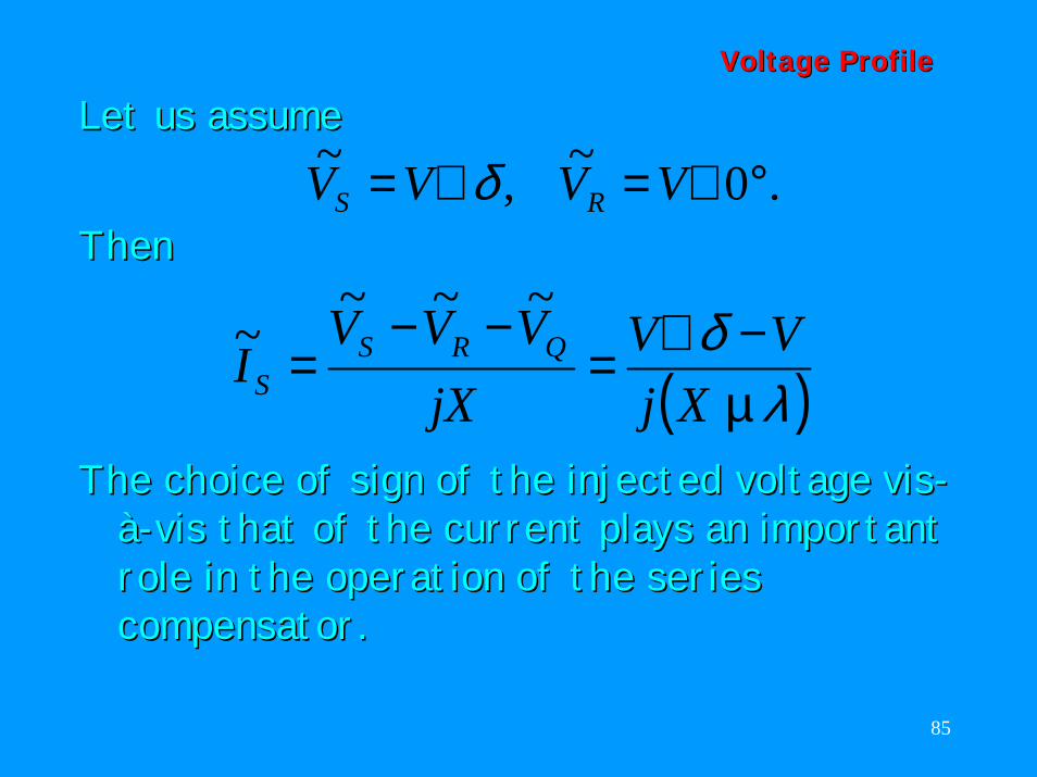
The choice of sign of the injected voltage The choice of sign of the injected voltage visvis--àà--visvis that of the current plays an important that of the current plays an important role in the operation of the series role in the operation of the series compensator.compensator.
Let us assumeLet us assume.0~,~ °∠=∠= VVVV RS δ
ThenThen
86
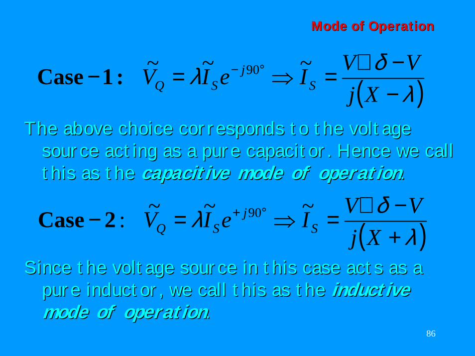
Mode of OperationMode of Operation
( )λδλ
−−∠=⇒=− °−
XjVVIeIV S
jSQ
~~~ 90:1Case
The above choice corresponds to the voltage The above choice corresponds to the voltage source acting as a pure capacitor. Hence we call source acting as a pure capacitor. Hence we call this as the this as the capacitive mode of operationcapacitive mode of operation..
( )λδλ
+−∠=⇒=− °+
XjVVIeIV S
jSQ
~~~: 902Case
Since the voltage source in this case acts as a Since the voltage source in this case acts as a pure inductor, we call this as the pure inductor, we call this as the inductive inductive mode of operationmode of operation..
87
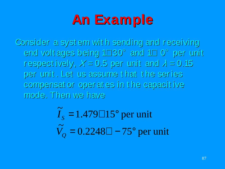
An ExampleAn ExampleConsider a system with sending and receiving Consider a system with sending and receiving
end voltages being 1end voltages being 1∠∠ 3030ºº and 1and 1∠∠ 00ºº per unit per unit respectively, respectively, XX = 0.5 per unit and = 0.5 per unit and λλ = 0.15 = 0.15 per unit. Let us assume that the series per unit. Let us assume that the series compensator operates in the capacitive compensator operates in the capacitive mode. Then we havemode. Then we have
unitper 752248.0~unitper 15479.1~
°−∠=
°∠=
Q
S
V
I
88
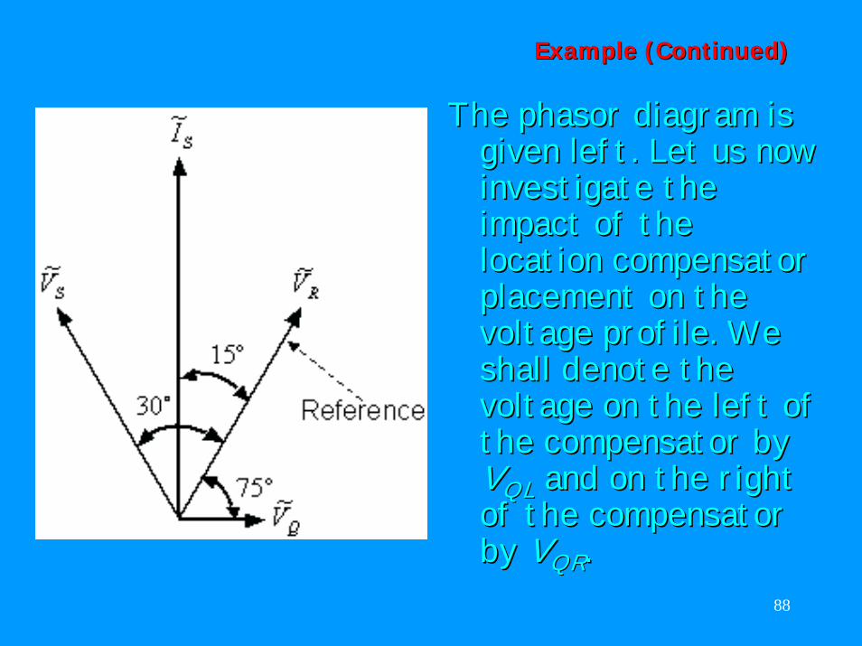
Example (Continued)Example (Continued)
The The phasor phasor diagram is diagram is given left. Let us now given left. Let us now investigate the investigate the impact of the impact of the location compensator location compensator placement on the placement on the voltage profile. We voltage profile. We shall denote the shall denote the voltage on the left of voltage on the left of the compensator by the compensator by VVQLQL and on the right and on the right of the compensator of the compensator by by VVQRQR..
89
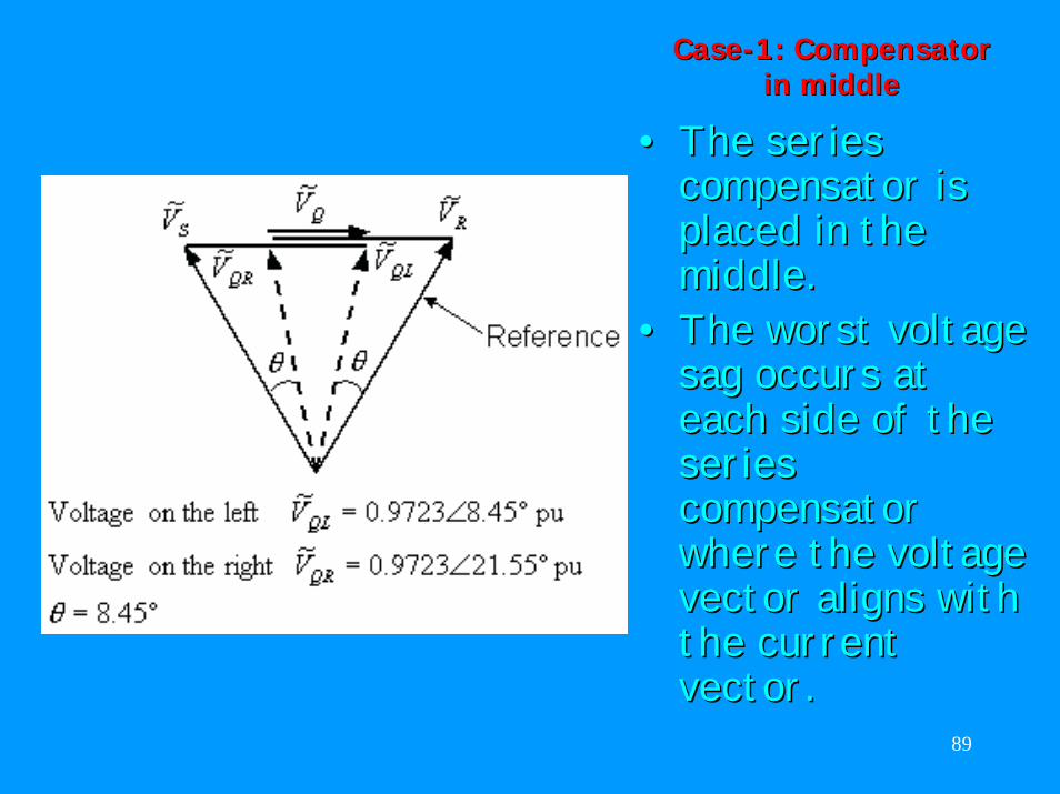
CaseCase--1: Compensator 1: Compensator in middlein middle
•• The series The series compensator is compensator is placed in the placed in the middle. middle.
•• The worst voltage The worst voltage sag occurs at sag occurs at each side of the each side of the series series compensator compensator where the voltage where the voltage vector aligns with vector aligns with the current the current vector.vector.
90
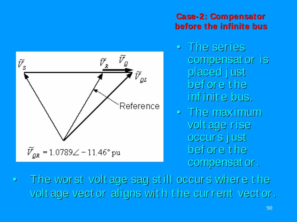
CaseCase--2: Compensator 2: Compensator before the infinite busbefore the infinite bus
•• The series The series compensator is compensator is placed just placed just before the before the infinite bus.infinite bus.
•• The maximum The maximum voltage rise voltage rise occurs just occurs just before the before the compensator.compensator.
•• The worst voltage sag still occurs where the The worst voltage sag still occurs where the voltage vector aligns with the current vector.voltage vector aligns with the current vector.
91
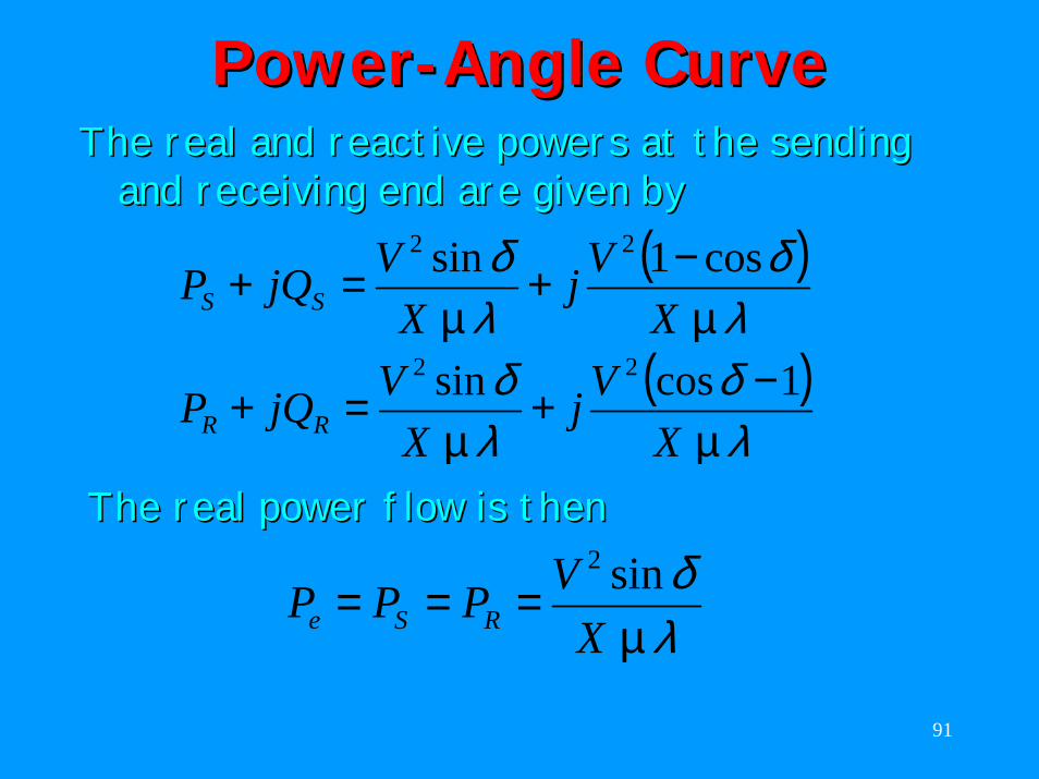
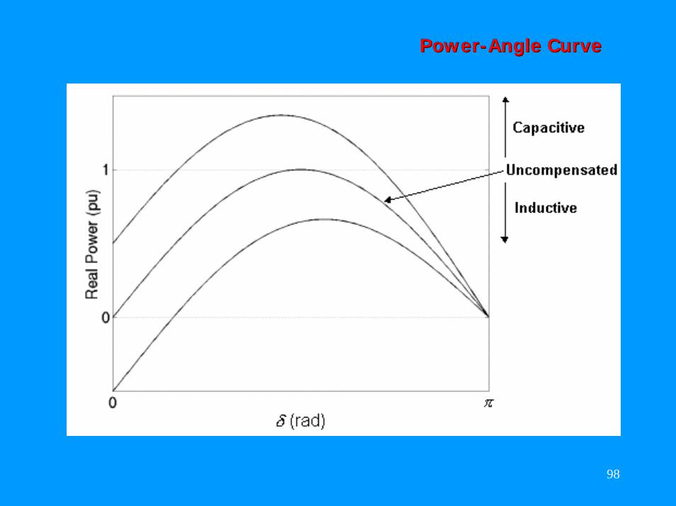
PowerPower--Angle CurveAngle CurveThe real and reactive powers at the sending The real and reactive powers at the sending
and receiving end are given byand receiving end are given by( )
( )λδ
λδ
λδ
λδ
µµ
µµ
XVj
XVjQP
XVj
XVjQP
RR
SS
1cossin
cos1sin
22
22
−+=+
−+=+
The real power flow is thenThe real power flow is then
λδ
µXVPPP RSe
sin2
===
92
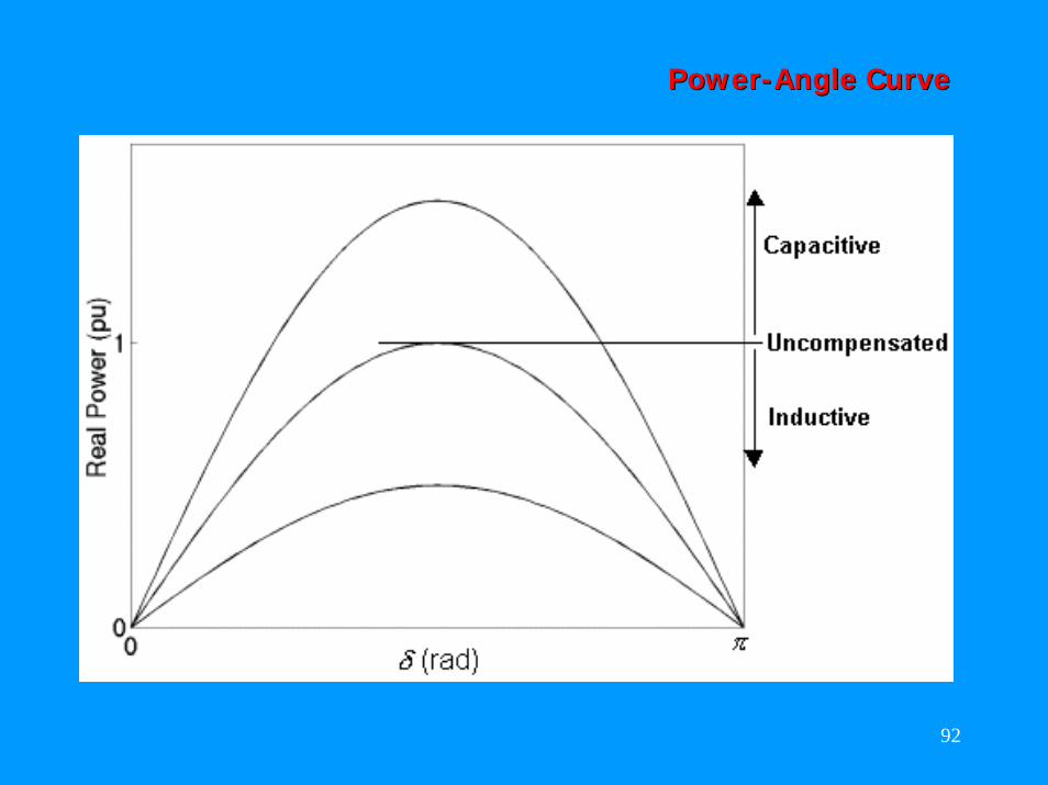
PowerPower--Angle CurveAngle Curve
93
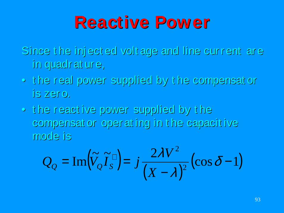
Reactive PowerReactive PowerSince the injected voltage and line current are Since the injected voltage and line current are
in in quadraturequadrature,,•• the real power supplied by the compensator the real power supplied by the compensator
is zero.is zero.•• the reactive power supplied by the the reactive power supplied by the
compensator operating in the capacitive compensator operating in the capacitive mode ismode is
( ) ( ) ( )1cos2~~Im 2
2
−−
== ∗ δλ
λX
VjIVQ SQQ
94
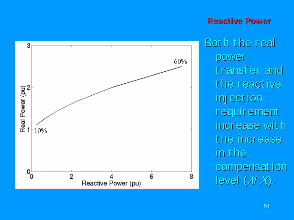
Reactive PowerReactive Power
Both the real Both the real power power transfer and transfer and the reactive the reactive injection injection requirement requirement increase with increase with the increase the increase in the in the compensation compensation level (level (λλ//XX).).
95
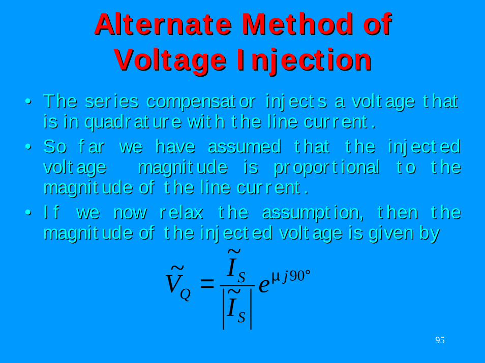
Alternate Method of Alternate Method of Voltage InjectionVoltage Injection
•• The series compensator injects a voltage that The series compensator injects a voltage that is inis in quadraturequadrature with the line current.with the line current.
•• So far we have assumed that the injected So far we have assumed that the injected voltage magnitude is proportional to the voltage magnitude is proportional to the magnitude of the line current. magnitude of the line current.
•• If we now relax the assumption, then the If we now relax the assumption, then the magnitude of the injected voltage is given bymagnitude of the injected voltage is given by
°= 90~~~ j
S
SQ e
IIV µ
96
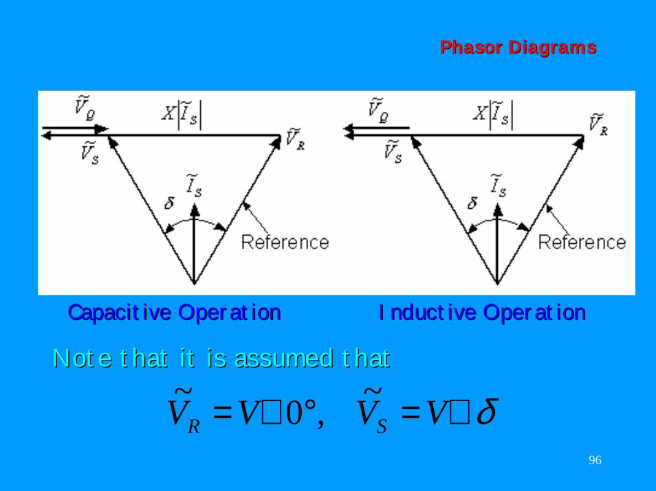
Phasor Phasor DiagramsDiagrams
Capacitive Operation Inductive OperationCapacitive Operation Inductive Operation
Note that it is assumed thatNote that it is assumed that
δ∠=°∠= VVVV SR~,0~
97
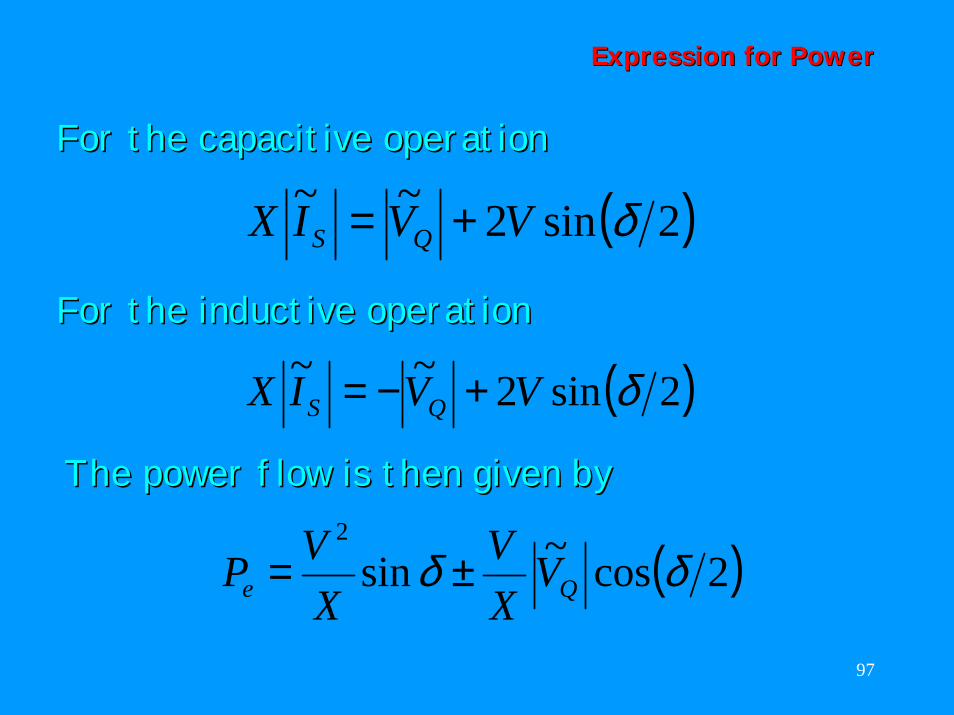
Expression for PowerExpression for Power
For the capacitive operationFor the capacitive operation
( )2sin2~~ δVVIX QS +=
The power flow is then given byThe power flow is then given by
( )2cos~sin2
δδ Qe VXV
XVP ±=
For the inductive operationFor the inductive operation
( )2sin2~~ δVVIX QS +−=
98
PowerPower--Angle CurveAngle Curve
99
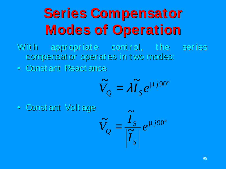
Series Compensator Series Compensator Modes of OperationModes of Operation
With appropriate control, the series With appropriate control, the series compensator operates in two modes:compensator operates in two modes:
•• Constant ReactanceConstant Reactance°= 90~~ j
SQ eIV µλ•• Constant VoltageConstant Voltage
°= 90~~~ j
S
SQ e
IIV µ
100
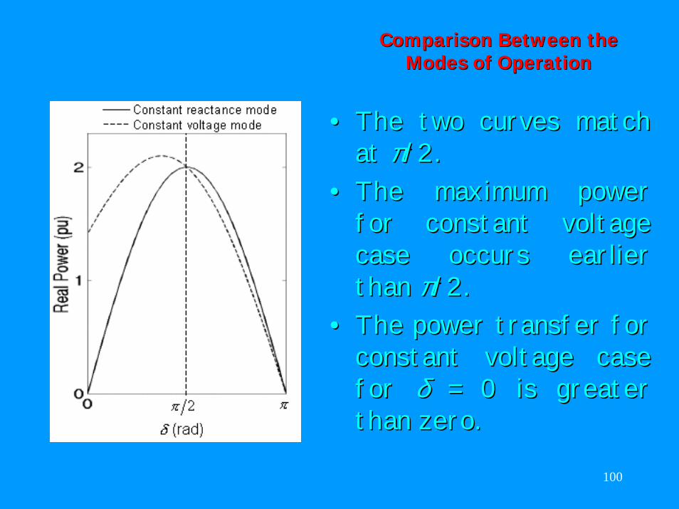
Comparison Between the Comparison Between the Modes of OperationModes of Operation
•• The two curves match The two curves match at at ππ/2/2. .
•• The maximum power The maximum power for constant voltage for constant voltage case occurs earlier case occurs earlier than than ππ/2. /2.
•• The power transfer for The power transfer for constant voltage case constant voltage case for for δδ = 0= 0 is greater is greater than zero.than zero.
101
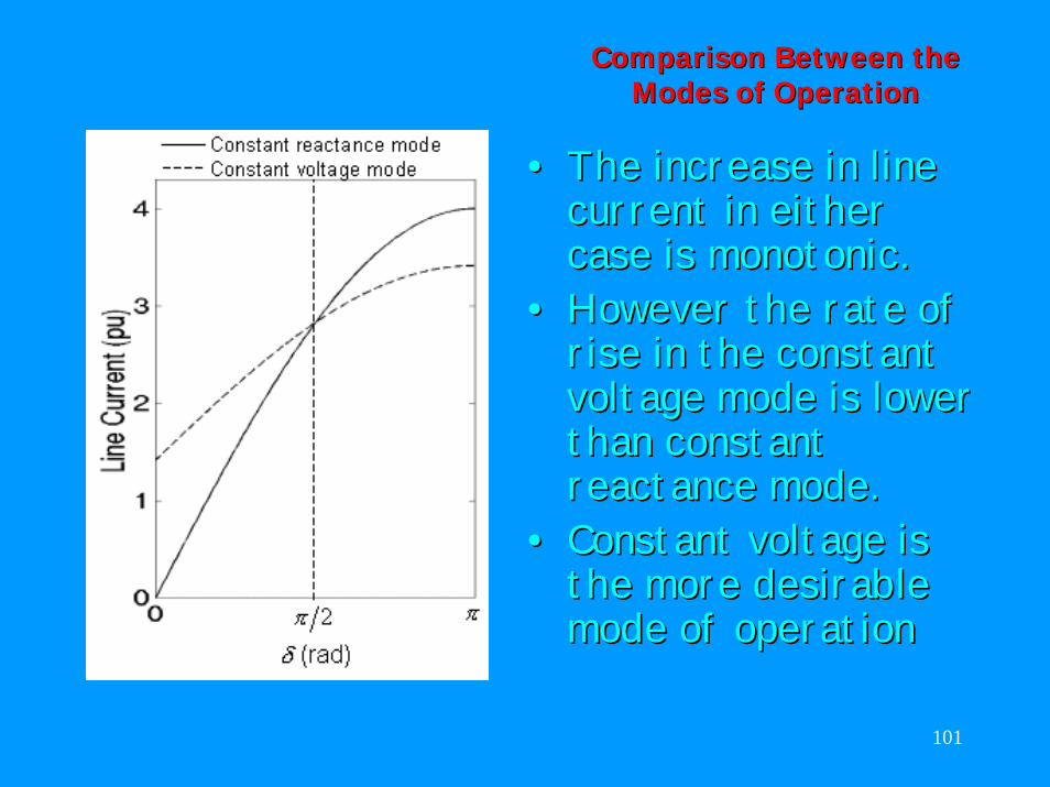
Comparison Between the Comparison Between the Modes of OperationModes of Operation
•• The increase in line The increase in line current in either current in either case is monotonic. case is monotonic.
•• However the rate of However the rate of rise in the constant rise in the constant voltage mode is lower voltage mode is lower than constant than constant reactance mode.reactance mode.
•• Constant voltage is Constant voltage is the more desirable the more desirable mode of operationmode of operation
102
Power Flow Control and Power Flow Control and Power Swing DampingPower Swing Damping
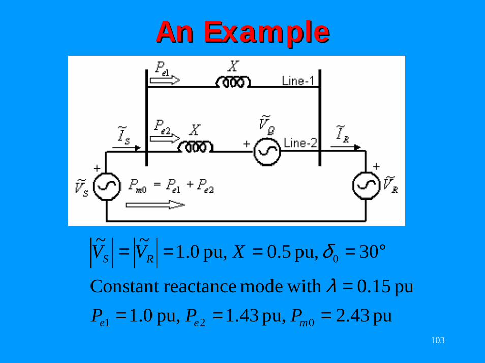
Let us consider an example to illustrateLet us consider an example to illustrate•• the power flow control andthe power flow control and•• The power swing dampingThe power swing dampingcapabilities of ideal series compensator. capabilities of ideal series compensator.
The system containsThe system contains•• a double circuit transmission linea double circuit transmission line•• one of the two lines compensated by an one of the two lines compensated by an
ideal series compensator.ideal series compensator.
103
An ExampleAn Example
pu 43.2 pu, 43.1 pu, 0.1pu 15.0 with mode reactanceConstant
30 pu, 5.0 pu, 1.0 ~~
021
0
====
°====
mee
RS
PPP
XVV
λ
δ
104
Example (Continued)Example (Continued)
For any increase or decrease in the power For any increase or decrease in the power flow, the series compensator can be flow, the series compensator can be controlled in one of the following two controlled in one of the following two modes.modes.
•• Regulating ControlRegulating Control: Channeling the increase : Channeling the increase (or decrease) in power through line(or decrease) in power through line--1. In 1. In this case the series compensator holds the this case the series compensator holds the power flow over linepower flow over line--2 constant.2 constant.
•• Tracking ControlTracking Control: Channeling the increase : Channeling the increase (or decrease) in power through line(or decrease) in power through line--2. In 2. In this case the series compensator helps in this case the series compensator helps in holding constant the power flow over lineholding constant the power flow over line--1.1.
105
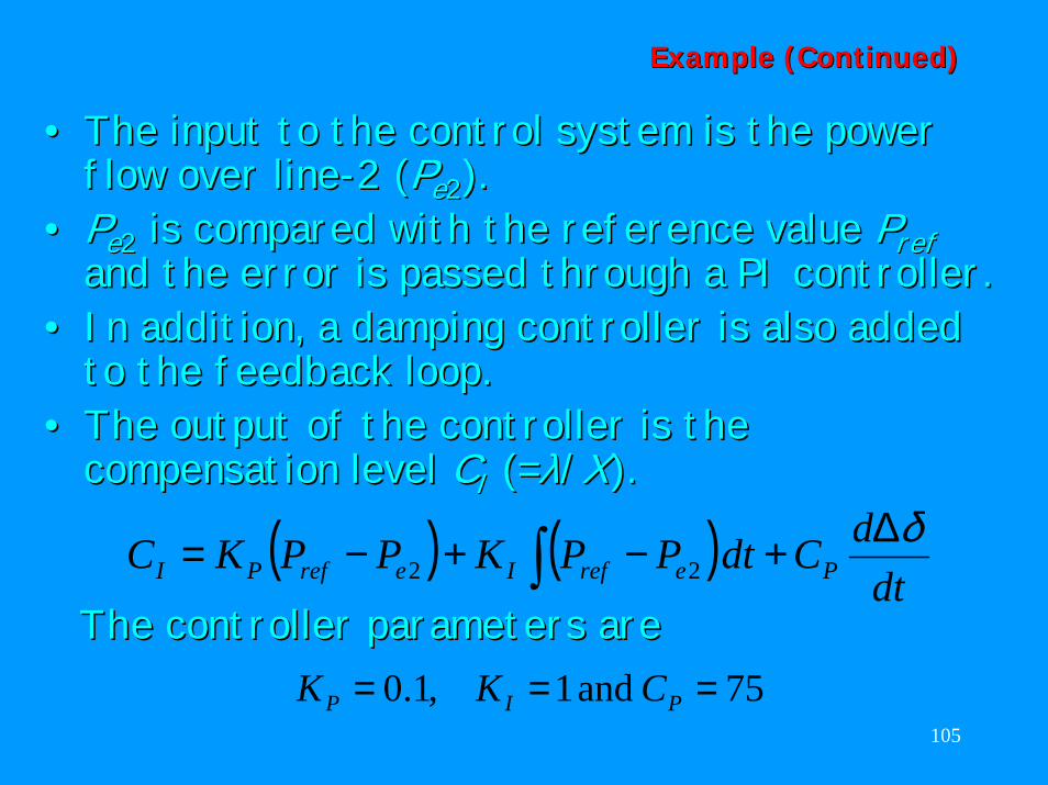
•• The input to the control system is the power The input to the control system is the power flow over lineflow over line--2 (2 (PPee22). ).
•• PPee22 is compared with the reference value is compared with the reference value PPrefrefand the error is passed through a PI controller.and the error is passed through a PI controller.
•• In addition, a damping controller is also added In addition, a damping controller is also added to the feedback loop.to the feedback loop.
•• The output of the controllerThe output of the controller is the is the compensation levelcompensation level CCII (=(=λλ//XX).).
( ) ( )dt
dCdtPPKPPKC PerefIerefPIδ∆+−+−= ∫ 22
TheThe controller parameters arecontroller parameters are75 and 1,1.0 === PIP CKK
Example (Continued)Example (Continued)
106
Example: Example: Regulating ControlRegulating Control
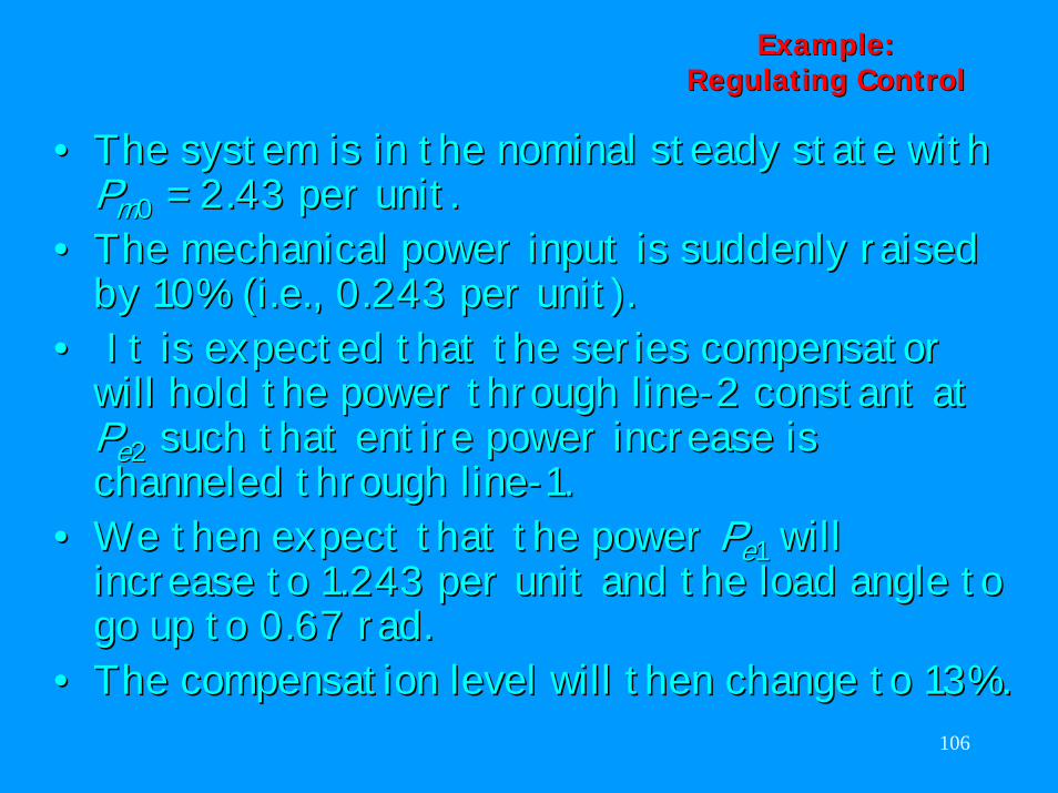
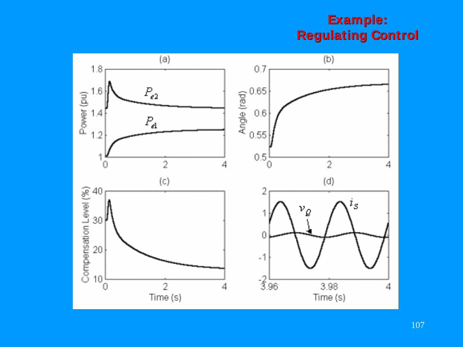
•• The system is in the nominal steady state with The system is in the nominal steady state with PPmm00 = 2.43 per unit.= 2.43 per unit.
•• The mechanical power input is suddenly raised The mechanical power input is suddenly raised by 10% (i.e., 0.243 per unit).by 10% (i.e., 0.243 per unit).
•• It is expected that the series compensator It is expected that the series compensator will hold the power through linewill hold the power through line--2 constant at 2 constant at PPee22 such that entire power increase is such that entire power increase is channeled through linechanneled through line--1.1.
•• We then expect that the power We then expect that the power PPee11 will will increase to 1.243 per unit and the load angle to increase to 1.243 per unit and the load angle to go up to 0.67go up to 0.67 radrad. .
•• The compensation level will then change to 13%.The compensation level will then change to 13%.
107
Example: Example: Regulating ControlRegulating Control
108
Example: Example: Tracking ControlTracking Control
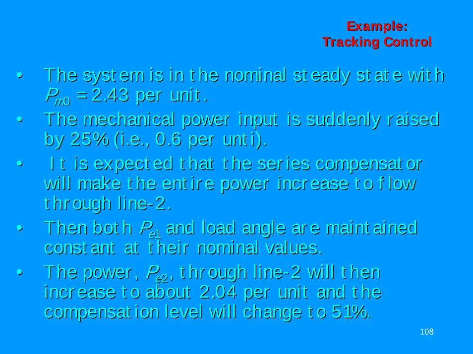
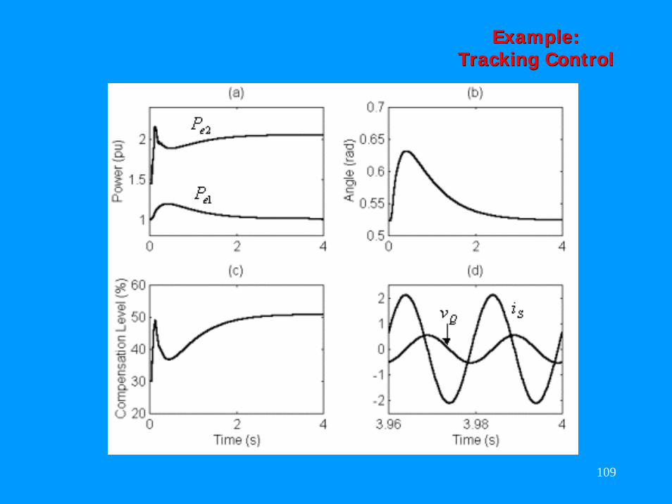
•• The system is in the nominal steady state with The system is in the nominal steady state with PPmm00 = 2.43 per unit.= 2.43 per unit.
•• The mechanical power input is suddenly raised The mechanical power input is suddenly raised by 25% (i.e., 0.6 per by 25% (i.e., 0.6 per untiunti).).
•• It is expected that the series compensator It is expected that the series compensator will make the entire power increase to flow will make the entire power increase to flow through linethrough line--2.2.
•• Then both Then both PPee11 and load angle are maintained and load angle are maintained constant at their nominal values. constant at their nominal values.
•• The power, The power, PPee22, through line, through line--2 will then 2 will then increase to about 2.04 per unit and the increase to about 2.04 per unit and the compensation level will change to 51%.compensation level will change to 51%.
109
Example: Example: Tracking ControlTracking Control
110
Practical Series CompensatorPractical Series Compensator
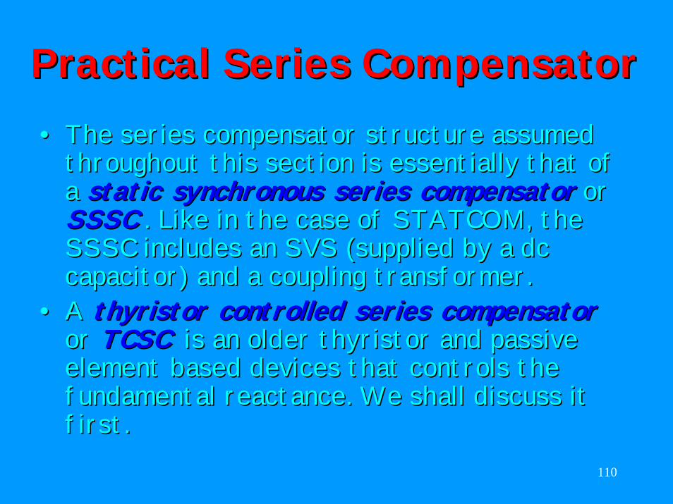
•• The series compensator structure assumed The series compensator structure assumed throughout this section is essentially that of throughout this section is essentially that of a a static synchronous series compensatorstatic synchronous series compensator or or SSSCSSSC . Like in the case of STATCOM, the . Like in the case of STATCOM, the SSSC includes an SVS (supplied by a dc SSSC includes an SVS (supplied by a dc capacitor) and a coupling transformer.capacitor) and a coupling transformer.
•• A A thyristor controlled series compensatorthyristor controlled series compensatoror or TCSCTCSC is an older thyristor and passive is an older thyristor and passive element based devices that controls the element based devices that controls the fundamental reactance. We shall discuss it fundamental reactance. We shall discuss it first.first.
111
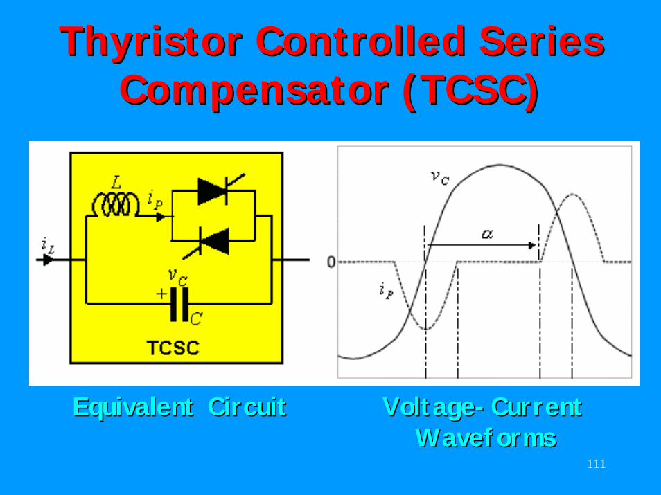
ThyristorThyristor Controlled Series Controlled Series Compensator (TCSC)Compensator (TCSC)
Equivalent CircuitEquivalent Circuit VoltageVoltage--CurrentCurrentWaveformsWaveforms
112
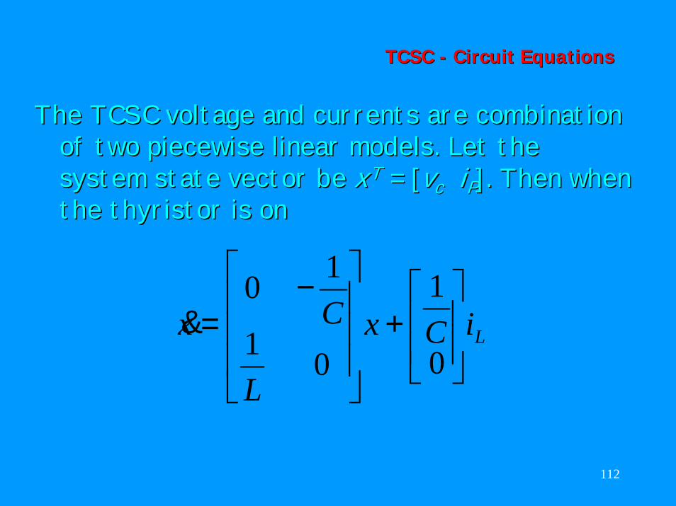
TCSC TCSC -- Circuit EquationsCircuit Equations
The TCSC voltage and currents are combination The TCSC voltage and currents are combination of two piecewise linear models. Let the of two piecewise linear models. Let the system state vector be system state vector be xxTT = [= [vvcc iiPP]. Then when ]. Then when the thyristor is onthe thyristor is on
LiCx
L
Cx
+
−=
0
1
01
10&
113
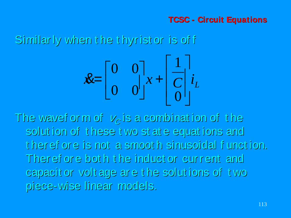
TCSC TCSC -- Circuit EquationsCircuit Equations
Similarly when the thyristor is offSimilarly when the thyristor is off
LiCxx
+
=
0
1
0000
&
The waveform of The waveform of vvCC is a combination of the is a combination of the solution of these two state equations and solution of these two state equations and therefore is not a smooth sinusoidal function. therefore is not a smooth sinusoidal function. Therefore both the inductor current and Therefore both the inductor current and capacitor voltage are the solutions of two capacitor voltage are the solutions of two piecepiece--wise linear models.wise linear models.
114
TCSC TCSC -- Fundamental Fundamental CharacteristicsCharacteristics
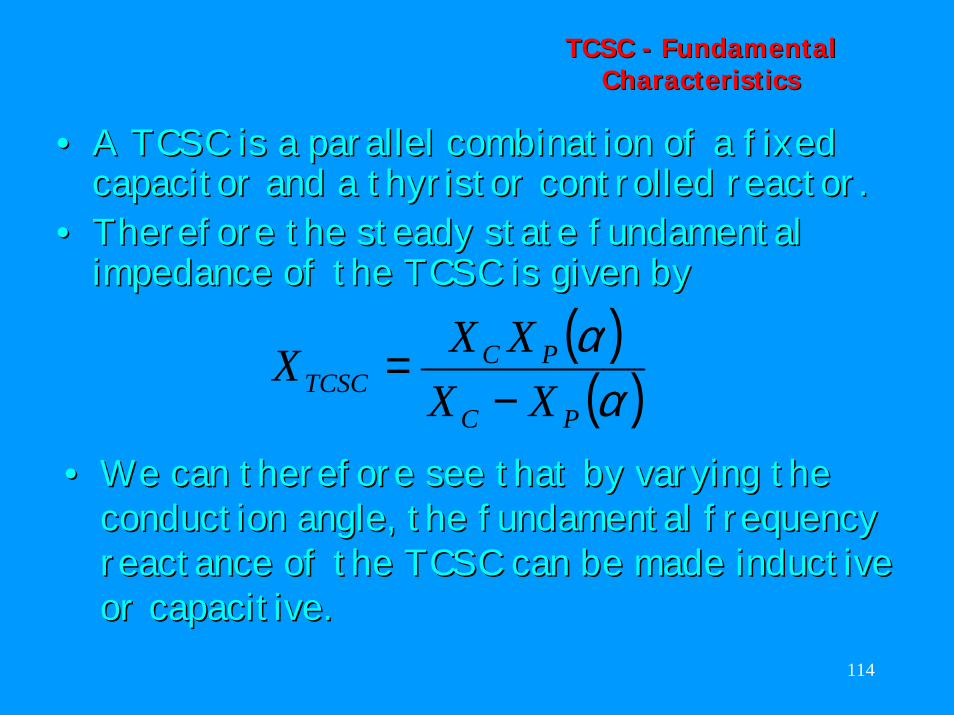
•• A TCSC is a parallel combination of a fixed A TCSC is a parallel combination of a fixed capacitor and a thyristor controlled reactor. capacitor and a thyristor controlled reactor.
•• Therefore the steady state fundamental Therefore the steady state fundamental impedance of the TCSC is given byimpedance of the TCSC is given by
( )( )αα
PC
PCTCSC XX
XXX−
=
•• We can therefore see that by varying the We can therefore see that by varying the conduction angle, the fundamental frequency conduction angle, the fundamental frequency reactance of the TCSC can be made inductive reactance of the TCSC can be made inductive or capacitive.or capacitive.
115
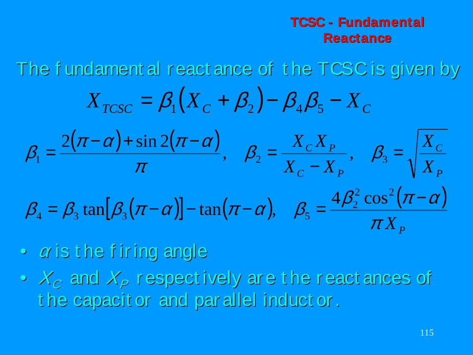
TCSC TCSC -- Fundamental Fundamental ReactanceReactance
The fundamental reactance of the TCSC is given byThe fundamental reactance of the TCSC is given by
( ) ( )
( )[ ] ( ) ( )P
P
C
PC
PC
X
XX
XXXX
παπββαπαπβββ
ββπ
απαπβ
−=−−−=
=−
=−+−=
222
5334
321
cos4,tantan
,,2sin2
( ) CCTCSC XXX −−+= 5421 ββββ
•• αα is the firing angleis the firing angle•• XXCC and and XXPP respectively are the respectively are the reactances reactances of of
the capacitor and parallel inductor.the capacitor and parallel inductor.
116
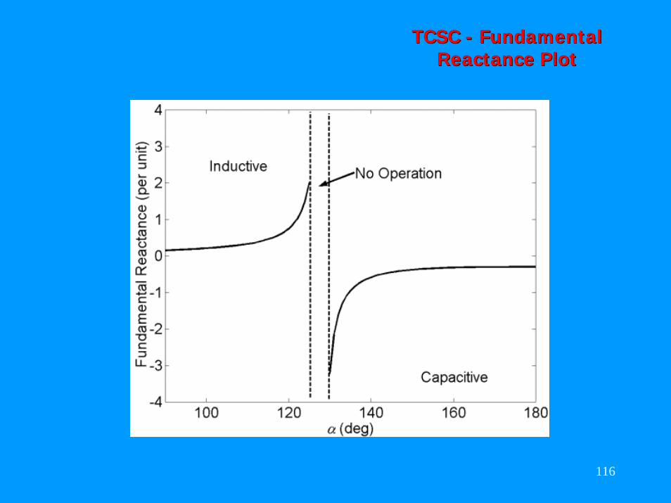
TCSC TCSC -- Fundamental Fundamental Reactance PlotReactance Plot
117
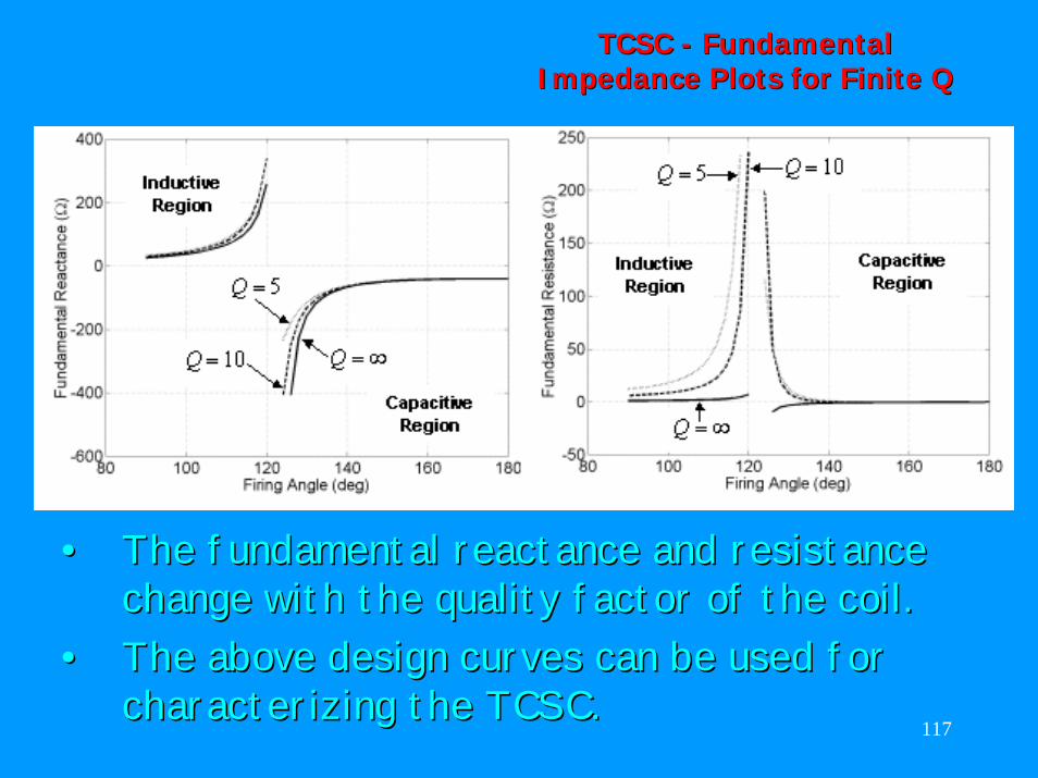
TCSC TCSC -- Fundamental Fundamental Impedance Plots for Finite QImpedance Plots for Finite Q
•• The fundamental reactance and resistance The fundamental reactance and resistance change with the quality factor of the coil. change with the quality factor of the coil.
•• The above design curves can be used for The above design curves can be used for characterizing the TCSC.characterizing the TCSC.
118
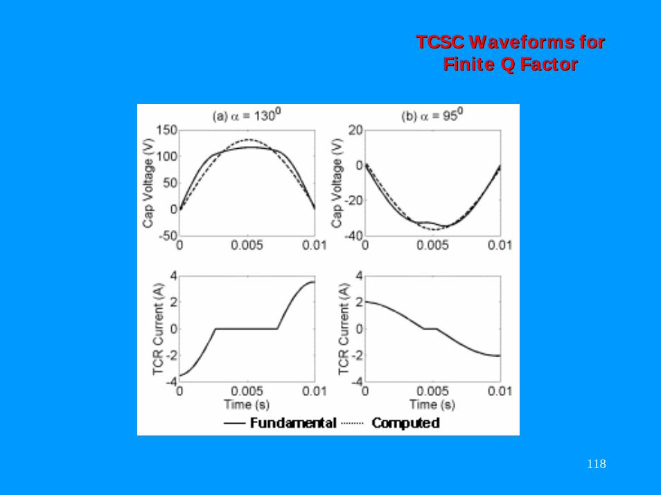
TCSC Waveforms for TCSC Waveforms for Finite Q FactorFinite Q Factor
119
TCSC ControlTCSC Control
A TCSC can be controlled in three modes.A TCSC can be controlled in three modes.Blocking Mode: Blocking Mode: •• The The thyristorsthyristors are not gated (i.e., the TCR is are not gated (i.e., the TCR is
blocked). blocked). •• The line current passes through the capacitor.The line current passes through the capacitor.•• The TCSC performs the task of a fixed series The TCSC performs the task of a fixed series
capacitor.capacitor.Bypass Mode:Bypass Mode:•• The thyristors are gated for full conduction The thyristors are gated for full conduction
of inductor current.of inductor current.•• The TCSC behaves as a parallel of fixed The TCSC behaves as a parallel of fixed
capacitor and inductor.capacitor and inductor.
120
TCSC ControlTCSC Control
Bypass Mode (continued):Bypass Mode (continued):•• The capacitor voltage is less for a given line The capacitor voltage is less for a given line
current. current. •• Therefore this mode is utilized to reduce Therefore this mode is utilized to reduce
capacitor stress during faults.capacitor stress during faults.VernierVernier Control Mode:Control Mode:•• The conducting angle of the TCSC is The conducting angle of the TCSC is
continuously varied to operate in either continuously varied to operate in either capacitive boost or inductive boost modes. capacitive boost or inductive boost modes.
•• In this mode the TCSC follows the In this mode the TCSC follows the fundamental reactance curve shown earlier.fundamental reactance curve shown earlier.
121
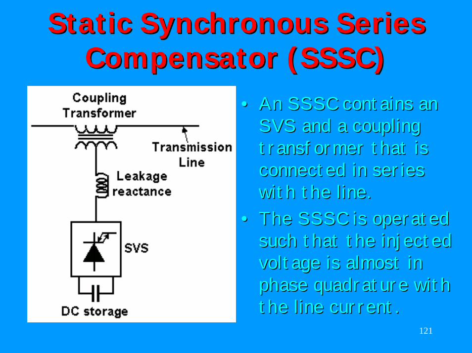
Static Synchronous Series Static Synchronous Series Compensator (SSSC)Compensator (SSSC)
•• An SSSC contains an An SSSC contains an SVS and a coupling SVS and a coupling transformer that is transformer that is connected in series connected in series with the line. with the line.
•• The SSSC is operated The SSSC is operated such that the injected such that the injected voltage is almost in voltage is almost in phase phase quadrature quadrature with with the line current.the line current.
122
Equivalent Circuit of SSSC Equivalent Circuit of SSSC Compensated SystemCompensated System
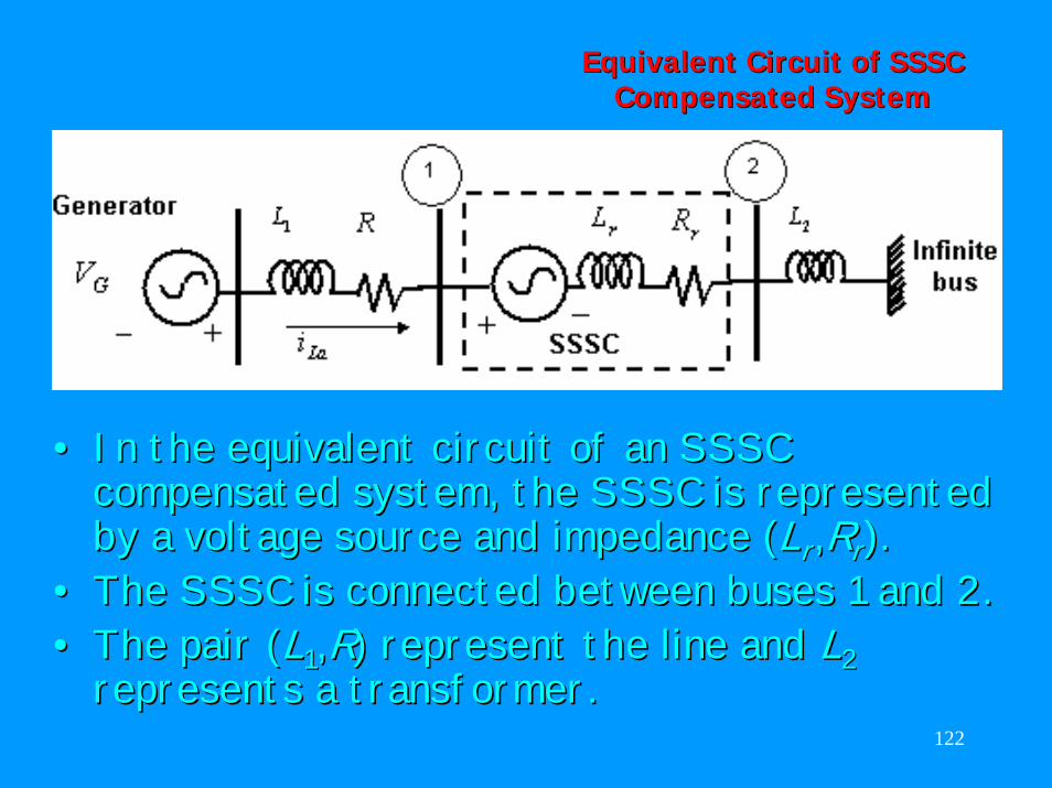
•• In the equivalent circuit of an SSSC In the equivalent circuit of an SSSC compensated system, the SSSC is represented compensated system, the SSSC is represented by a voltage source and impedance (by a voltage source and impedance (LLrr,,RRrr).).
•• The SSSC is connected between buses 1 and 2.The SSSC is connected between buses 1 and 2.•• The pair (The pair (LL11,,RR) represent the line and ) represent the line and LL22
represents a transformer.represents a transformer.
123
SSSC ControlSSSC Control
124
SSSC ControlSSSC Control
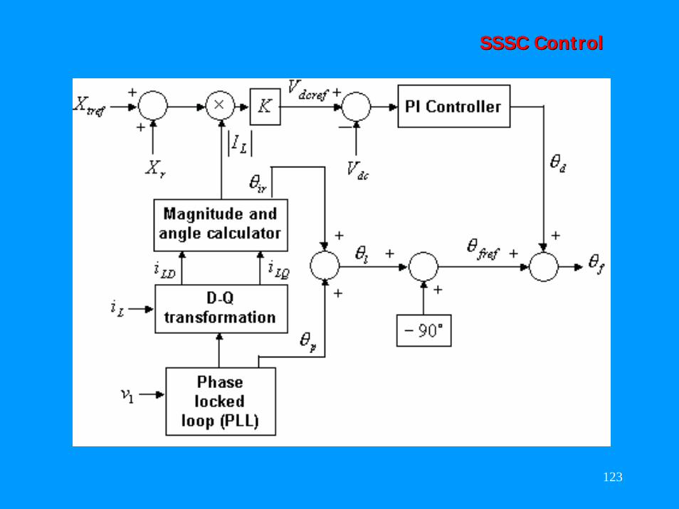
•• An instantaneous 3An instantaneous 3--phase set of line voltages phase set of line voltages at bus 1 is used to calculate the angle at bus 1 is used to calculate the angle θθ that that is phase locked to the phaseis phase locked to the phase--a of the line a of the line voltage.voltage.
•• An instantaneous 3An instantaneous 3--phase set of measured line phase set of measured line currents is first decomposed into real and currents is first decomposed into real and reactive components. reactive components.
•• The amplitude and the relative angle of the The amplitude and the relative angle of the line current line current θθirir are then calculated. are then calculated.
•• The phase locked angle The phase locked angle θθp p and and θθirir are added to are added to obtain the angle obtain the angle θθll which is the angle of the which is the angle of the line current. line current.
125
SSSC ControlSSSC Control
•• The are two control loops. The are two control loops. •• Since the SSSC voltage must lag the line current Since the SSSC voltage must lag the line current
by 90by 90ºº, a fixed angle equal to , a fixed angle equal to --9090ºº is added to is added to θθllto obtain to obtain θθfreffref in the main loop.in the main loop.
•• In the auxiliary loop, the reactance demand In the auxiliary loop, the reactance demand XXtreftrefis added to is added to XXrr of SSSC. of SSSC.
•• The sum is multiplied by the magnitude of the The sum is multiplied by the magnitude of the line current and a constant to obtain line current and a constant to obtain VVdcrefdcref..
•• The error between The error between VVdcrefdcref and theand the actual value of actual value of VVdcdc is passed through a PI controller to obtain is passed through a PI controller to obtain θθdd..
•• This quantity is then added to This quantity is then added to θθfreffref to obtain to obtain θθffof the inverter.of the inverter.
126
SSSC ControlSSSC Control
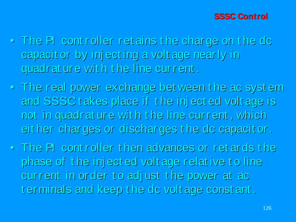
•• The PI controller retains the charge on the dc The PI controller retains the charge on the dc capacitor by injecting a voltage nearly in capacitor by injecting a voltage nearly in quadraturequadrature with the line current. with the line current.
•• The real power exchange between the ac system The real power exchange between the ac system and SSSC takes place if the injected voltage is and SSSC takes place if the injected voltage is not innot in quadraturequadrature with the line current, which with the line current, which either charges or discharges the dc capacitor. either charges or discharges the dc capacitor.
•• The PI controller then advances or retards the The PI controller then advances or retards the phase of the injected voltage relative to line phase of the injected voltage relative to line current in order to adjust the power at ac current in order to adjust the power at ac terminals and keep the dc voltage constant. terminals and keep the dc voltage constant.
127
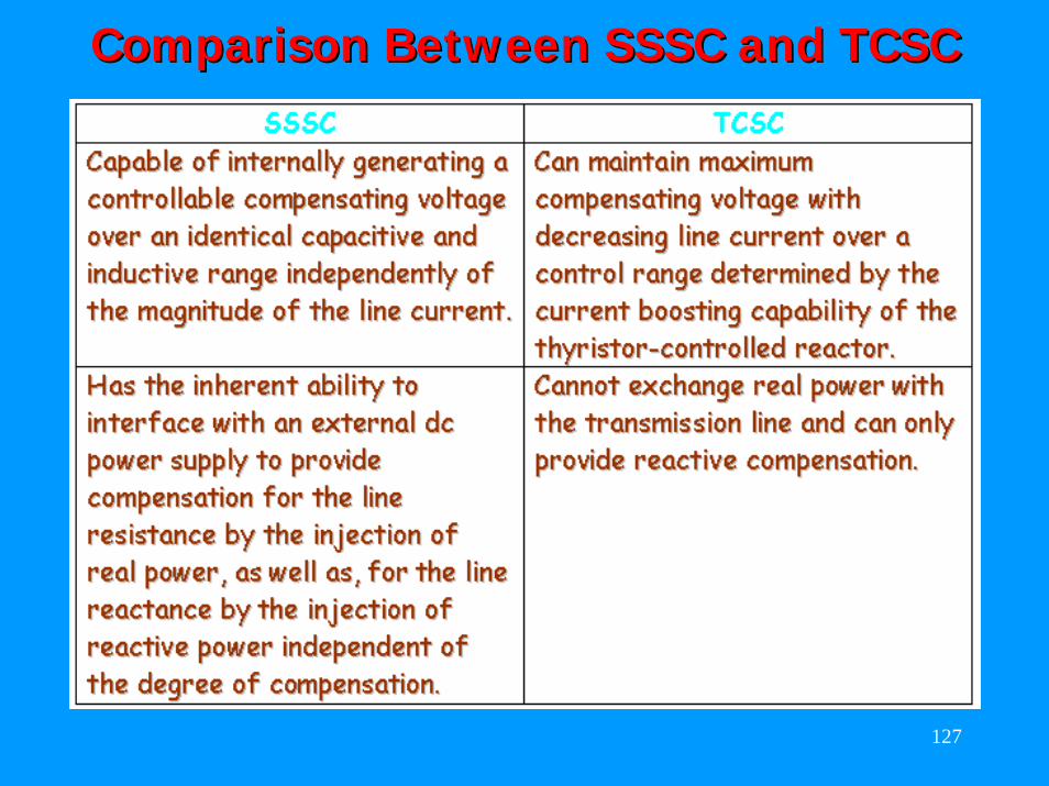
Comparison Between SSSC and TCSCComparison Between SSSC and TCSC
128
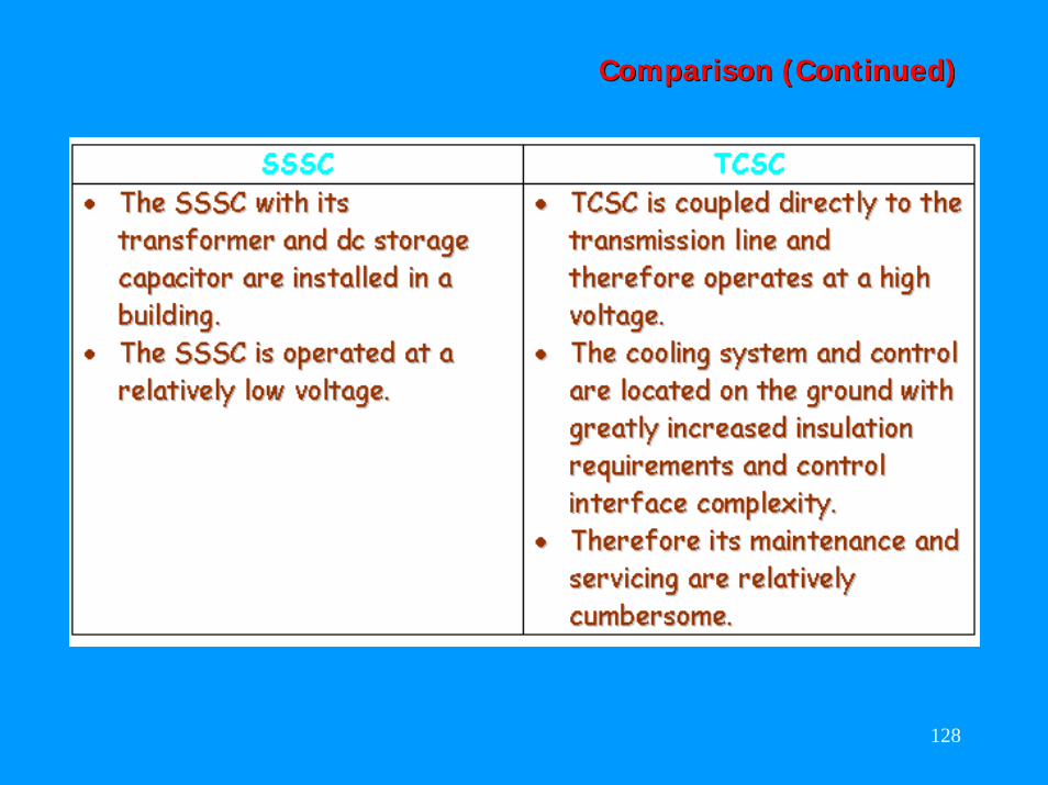
Comparison (Continued)Comparison (Continued)
129
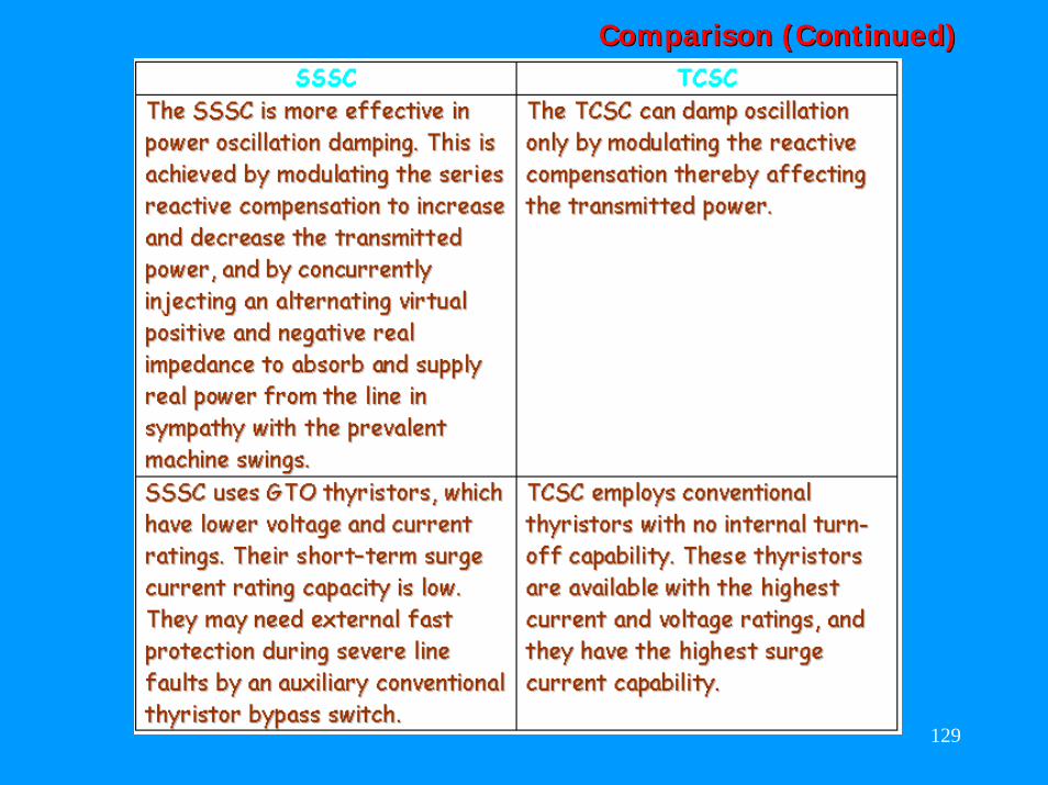
Comparison (Continued)Comparison (Continued)
130
Other FACTS ControllersOther FACTS Controllers
There are many other FACTS controllers that There are many other FACTS controllers that use the power electronic technology. We use the power electronic technology. We shall briefly discuss the following:shall briefly discuss the following:
•• Interline Power Flow Controller (IPFC)Interline Power Flow Controller (IPFC)•• Thyristor Thyristor Controlled Braking Resistor Controlled Braking Resistor
(TCBR)(TCBR)•• Thyristor Thyristor Controlled Phase Angle Regulator Controlled Phase Angle Regulator
(TCPAR)(TCPAR)•• Unified Power Flow Controller (UPFC)Unified Power Flow Controller (UPFC)
131
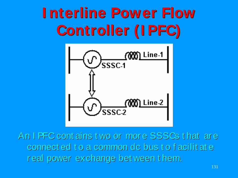
Interline Power Flow Interline Power Flow Controller (IPFC)Controller (IPFC)
An IPFC contains two or more An IPFC contains two or more SSSCs SSSCs that are that are connected to a common dc bus to facilitate connected to a common dc bus to facilitate real power exchange between them.real power exchange between them.
132
IPFC (Continued)IPFC (Continued)
•• Each individual SSSC can provide controllable Each individual SSSC can provide controllable series compensation to the line it is connected. series compensation to the line it is connected.
•• In addition, it can also exchange power In addition, it can also exchange power between them. between them.
•• Example: Assume that LineExample: Assume that Line--1 is lightly loaded 1 is lightly loaded while Linewhile Line--2 is heavily loaded. 2 is heavily loaded.
•• SSSCSSSC--1 then absorbs power to charge the dc 1 then absorbs power to charge the dc capacitor.capacitor.
•• SSSCSSSC--2 is then supplied real power by the dc 2 is then supplied real power by the dc capacitor. capacitor.
•• In this way the load sharing between the lines In this way the load sharing between the lines can be equalized.can be equalized.
133
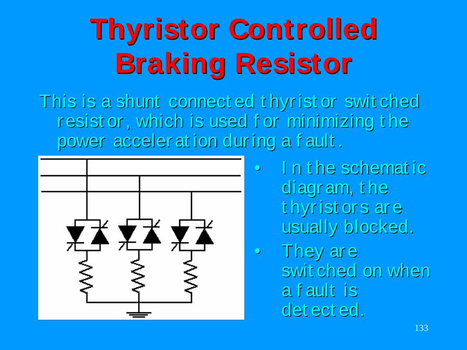
Thyristor Thyristor Controlled Controlled Braking ResistorBraking Resistor
This is a shunt connected This is a shunt connected thyristor thyristor switched switched resistor, which is used for minimizing the resistor, which is used for minimizing the power acceleration during a fault.power acceleration during a fault.
•• In the schematic In the schematic diagram, the diagram, the thyristorsthyristors are are usually blocked. usually blocked.
•• They are They are switched on when switched on when a fault is a fault is detected. detected.
134
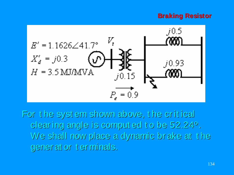
Braking ResistorBraking Resistor
For the system shown above, the critical For the system shown above, the critical clearing angle is computed to be 52.24º. clearing angle is computed to be 52.24º. We shall now place a dynamic brake at the We shall now place a dynamic brake at the generator terminals.generator terminals.
135
Braking ResistorBraking Resistor
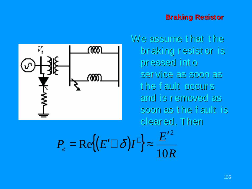
( ){ }R
EIEPe 10Re
2′≈∠′= ∗δ
We assume that the We assume that the braking resistor is braking resistor is pressed into pressed into service as soon as service as soon as the fault occurs the fault occurs and is removed as and is removed as soon as the fault is soon as the fault is cleared. Thencleared. Then
136
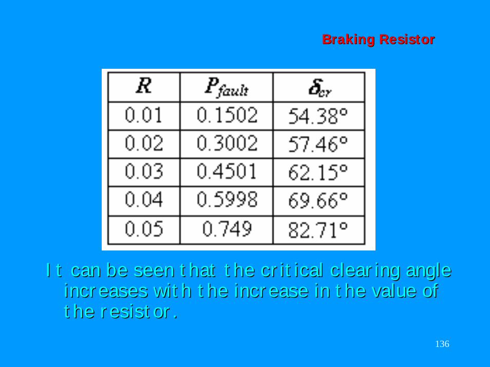
Braking ResistorBraking Resistor
It can be seen that the critical clearing angle It can be seen that the critical clearing angle increases with the increase in the value of increases with the increase in the value of the resistor.the resistor.
137
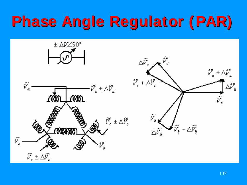
Phase Angle Regulator (PAR)Phase Angle Regulator (PAR)
138
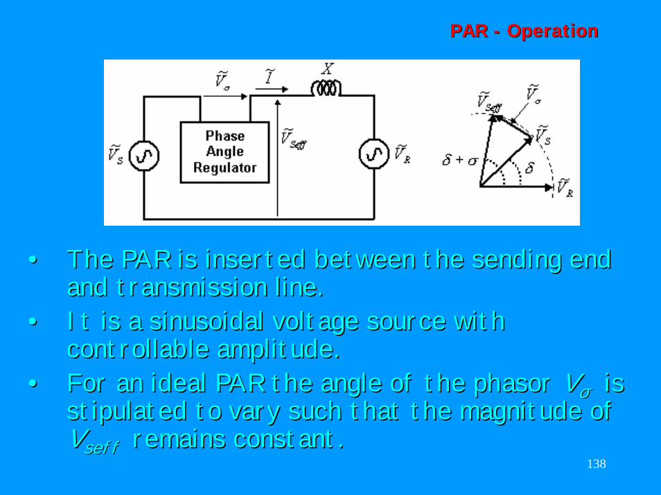
PAR PAR -- OperationOperation
•• The PAR is inserted between the sending end The PAR is inserted between the sending end and transmission line. and transmission line.
•• It is a sinusoidal voltage source with It is a sinusoidal voltage source with controllable amplitude. controllable amplitude.
•• For an ideal PAR the angle of the For an ideal PAR the angle of the phasor phasor VVσσ is is stipulated to vary such that the magnitude of stipulated to vary such that the magnitude of VVseff seff remains constant.remains constant.
139
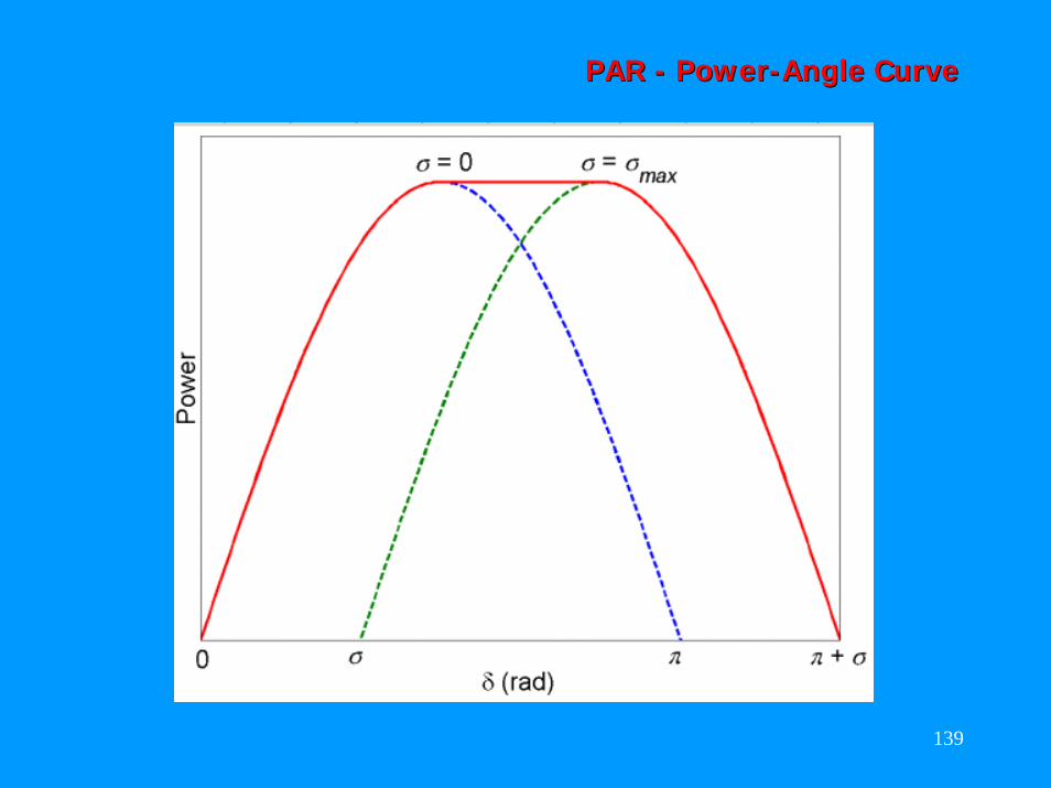
PAR PAR -- PowerPower--Angle CurveAngle Curve
140
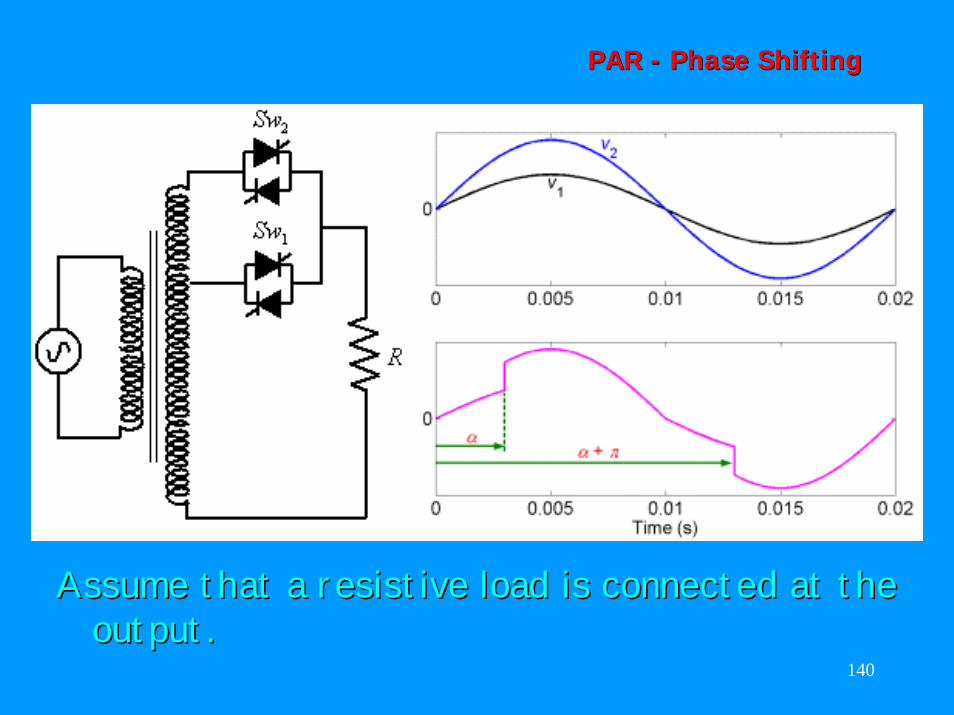
PAR PAR -- Phase ShiftingPhase Shifting
Assume that a resistive load is connected at the Assume that a resistive load is connected at the output.output.
141
PAR PAR -- Phase ShiftingPhase Shifting
The voltages obtained at the lower and upper The voltages obtained at the lower and upper taps are taps are vv11 and and vv22 respectively. respectively.
•• At the zero crossing of these voltages, the At the zero crossing of these voltages, the switch switch SwSw11 is turned on.is turned on.
•• At At αα the switch the switch SwSw22 is turned on. is turned on. •• This commutates the current of This commutates the current of SwSw11 by by
forcing a negative anode to cathode voltage forcing a negative anode to cathode voltage across it, thereby making the voltage across across it, thereby making the voltage across the load the load vv22. .
•• The switch The switch SwSw22 turns off when the current turns off when the current through it reverses.through it reverses.
142
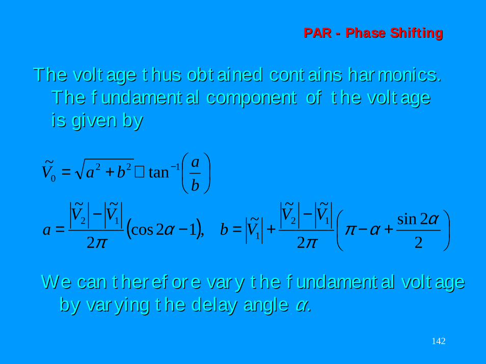
PAR PAR -- Phase ShiftingPhase Shifting
The voltage thus obtained contains harmonics. The voltage thus obtained contains harmonics. The fundamental component of the voltage The fundamental component of the voltage is given byis given by
( )
+−
−+=−
−=
∠+= −
22sin
2
~~~,12cos
2
~~
tan~
121
12
1220
ααππ
απ
VVVb
VVa
babaV
We can therefore vary the fundamental voltage We can therefore vary the fundamental voltage by varying the delay angle by varying the delay angle αα ..
143
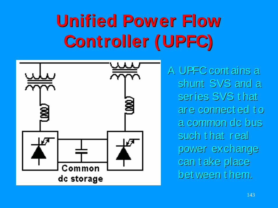
Unified Power Flow Unified Power Flow Controller (UPFC)Controller (UPFC)
A UPFC contains a A UPFC contains a shunt SVS and a shunt SVS and a series SVS that series SVS that are connected to are connected to a common dc bus a common dc bus such that real such that real power exchange power exchange can take place can take place between them.between them.
144
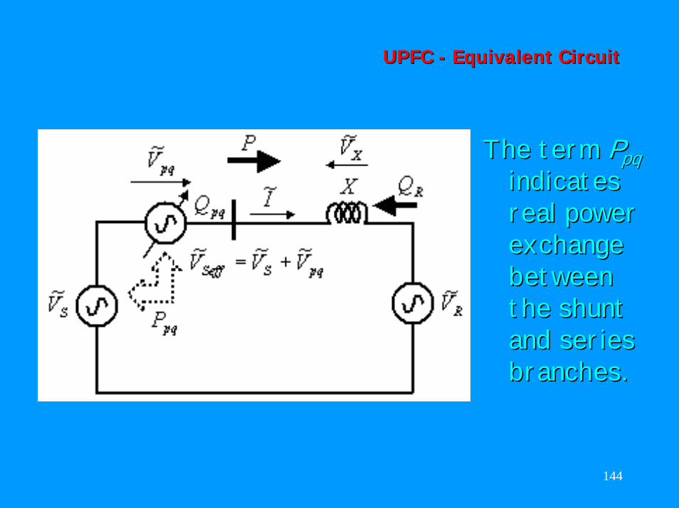
UPFC UPFC -- Equivalent CircuitEquivalent Circuit
The term The term PPpqpqindicates indicates real power real power exchange exchange between between the shunt the shunt and series and series branches.branches.
145
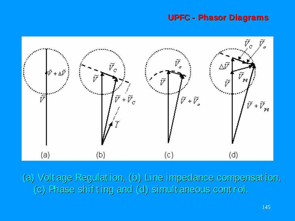
UPFC UPFC -- PhasorPhasor DiagramsDiagrams
(a) Voltage Regulation, (b) Line impedance compensation, (a) Voltage Regulation, (b) Line impedance compensation, (c) Phase shifting and (d) simultaneous control.(c) Phase shifting and (d) simultaneous control.
146
UPFC UPFC -- Real & Reactive PowerReal & Reactive Power
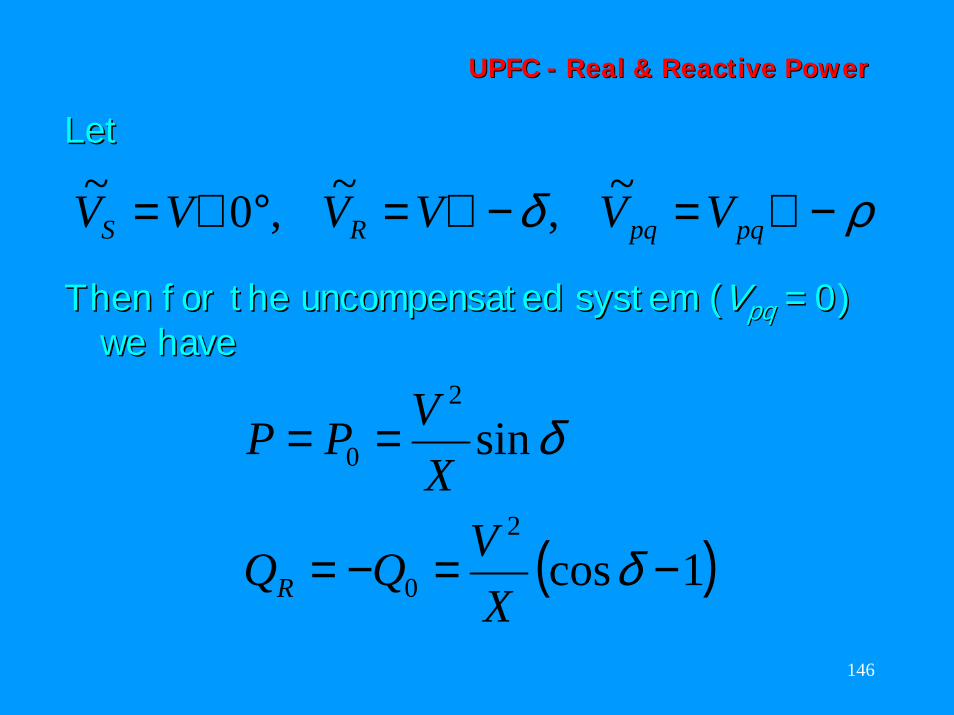
LetLet
ρδ −∠=−∠=°∠= pqpqRS VVVVVV ~,~,0~
Then for the uncompensated system (Then for the uncompensated system (VVpqpq = 0) = 0) we havewe have
( )1cos
sin
2
0
2
0
−=−=
==
δ
δ
XVQQ
XVPP
R
147
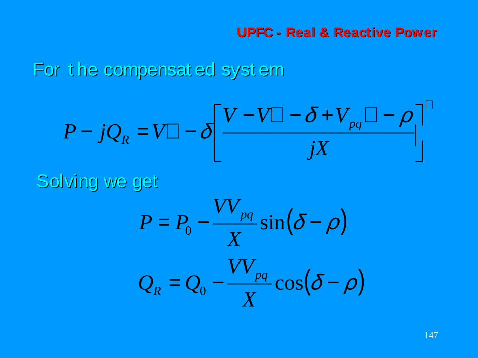
UPFC UPFC -- Real & Reactive PowerReal & Reactive Power
For the compensated systemFor the compensated system
∗
−∠+−∠−−∠=−
jXVVV
VjQP pqR
ρδδ
Solving we getSolving we get
( )
( )ρδ
ρδ
−−=
−−=
cos
sin
0
0
XVV
XVV
PP
pqR
pq
148
UPFC UPFC -- Real & Reactive PowerReal & Reactive Power
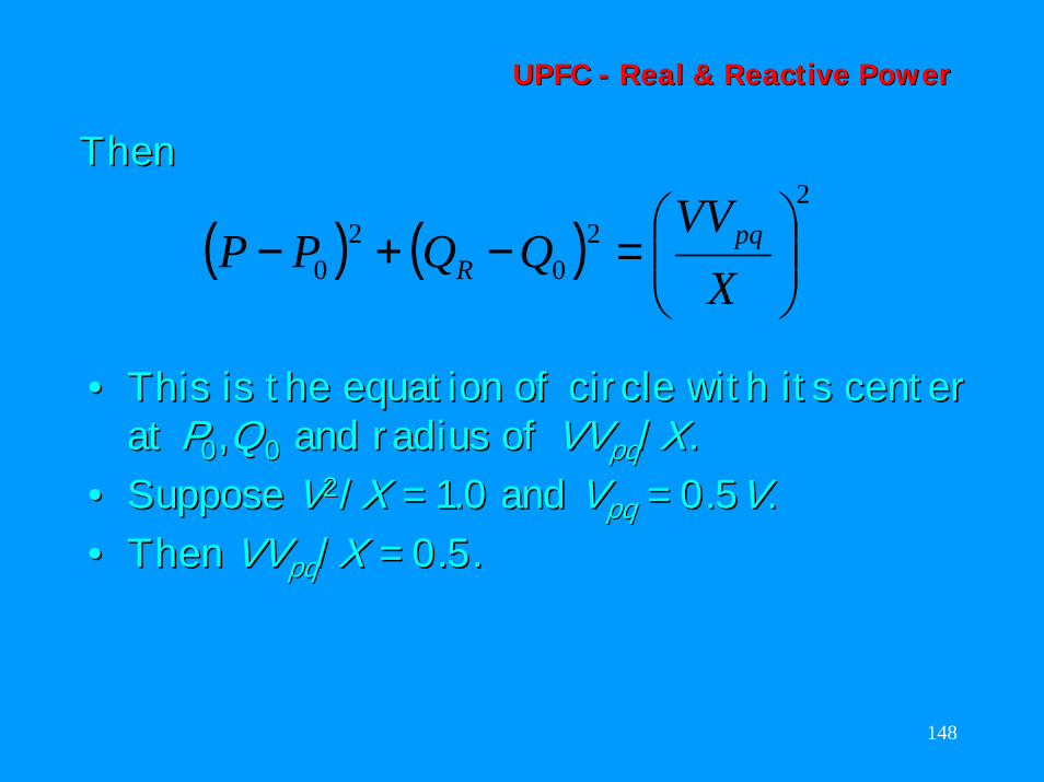
ThenThen
•• This is the equation of circle with its center This is the equation of circle with its center at at PP00,,QQ00 and radius of and radius of VVVVpqpq//XX..
•• Suppose Suppose VV22//XX = 1.0 and = 1.0 and VVpqpq = 0.5= 0.5VV. . •• Then Then VVVVpqpq//XX = 0.5.= 0.5.
( ) ( )2
20
20
=−+−
XVV
QQPP pqR
149
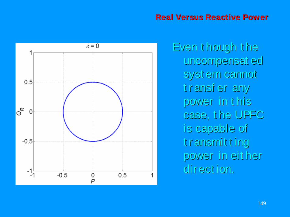
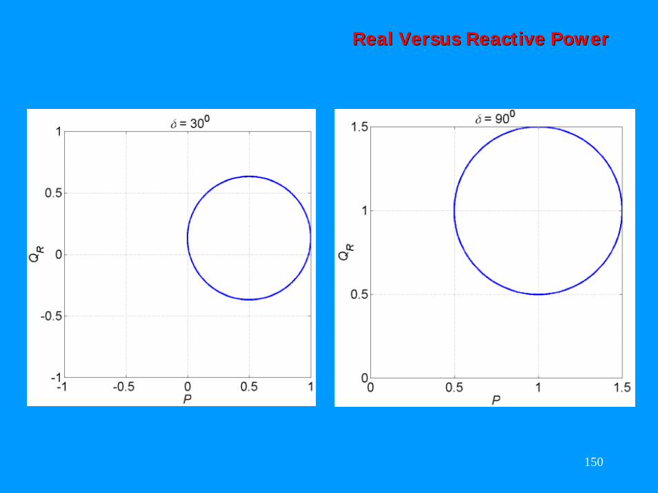
Real Versus Reactive PowerReal Versus Reactive Power
Even though the Even though the uncompensated uncompensated system cannot system cannot transfer any transfer any power in this power in this case, the UPFC case, the UPFC is capable of is capable of transmitting transmitting power in either power in either direction.direction.
150
Real Versus Reactive PowerReal Versus Reactive Power
151
RealReal vsvs Reactive PowerReactive Power
•• The figures show that the UPFC has the The figures show that the UPFC has the unique capability to control independently unique capability to control independently the real and reactive power flow at any the real and reactive power flow at any transmission angle. transmission angle.
•• It is however assumed here that the It is however assumed here that the sending and receiving end voltages are sending and receiving end voltages are provided by independent power systems provided by independent power systems which are able to supply and absorb real which are able to supply and absorb real power without any internal angular change.power without any internal angular change.
•• In practice the situation will be different In practice the situation will be different depending on the change in load angle.depending on the change in load angle.