Embed Size (px)
Citation preview
David
Nis
bet
– LIU
WG
17
th J
uly
2008
LIUWG – Options for Powering Phase I
David Nisbet
•Summary of points from LIUWG 7
•Existing topology
•Future topology ideas
•Overview of possible topologies
•Summary of options
•Discussion…
David
Nis
bet
– LIU
WG
17
th J
uly
2008
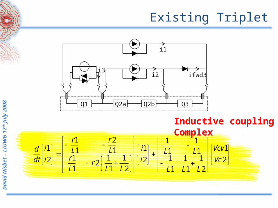
Existing Triplet
Q3Q2bQ2aQ1
i1
i2i3
ifwd3
Inductive couplingComplex
David
Nis
bet
– LIU
WG
17
th J
uly
2008
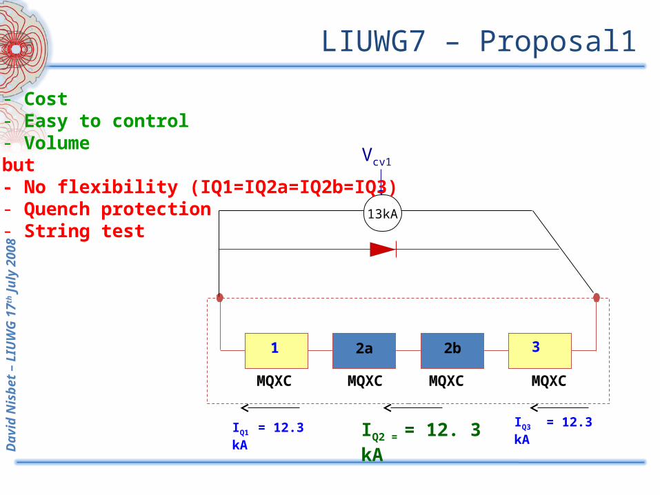
1 2a 32b
MQXC MQXCMQXC MQXC
IQ2 = = 12. 3 kA IQ3 = 12.3 kAIQ1 = 12.3 kA
13kA
Vcv1
- Cost - Easy to control- Volumebut- No flexibility (IQ1=IQ2a=IQ2b=IQ3)- Quench protection- String test
LIUWG7 – Proposal1
David
Nis
bet
– LIU
WG
17
th J
uly
2008
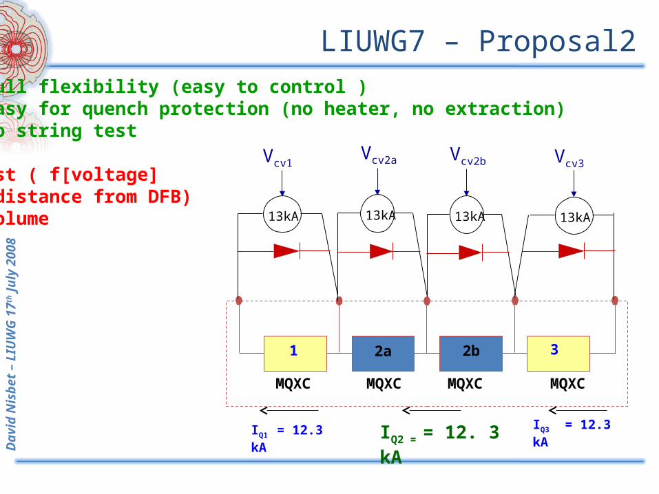
13kA
Vcv2b
1 2a 32b
MQXC MQXCMQXC MQXC
IQ2 = = 12. 3 kA IQ3 = 12.3 kAIQ1 = 12.3 kA
13kA
Vcv1
13kA
Vcv3
13kA
Vcv2a
- Full flexibility (easy to control )- Easy for quench protection (no heater, no extraction)- no string testbut-Cost ( f[voltage] => distance from DFB)- volume
LIUWG7 – Proposal2
David
Nis
bet
– LIU
WG
17
th J
uly
2008
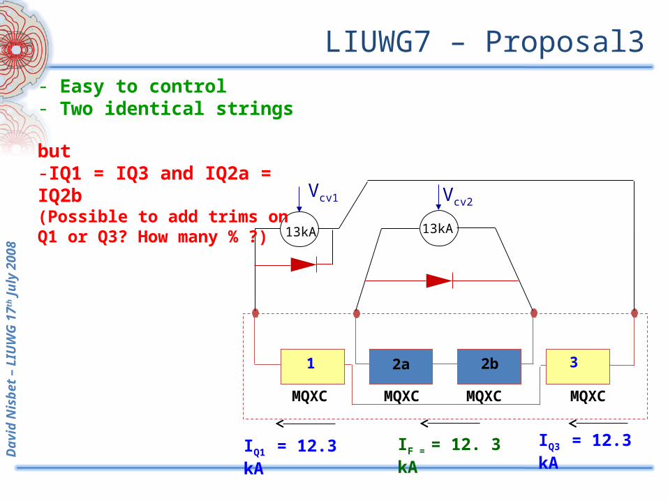
1 2a 32b
13kA13kA
Vcv1 Vcv2
MQXC MQXCMQXC MQXC
IF = = 12. 3 kA IQ3 = 12.3 kAIQ1 = 12.3 kA
- Easy to control - Two identical strings
but-IQ1 = IQ3 and IQ2a = IQ2b (Possible to add trims on Q1 or Q3? How many % ?)
LIUWG7 – Proposal3
David
Nis
bet
– LIU
WG
17
th J
uly
2008
Phase I Triplet – LIUWG7 Proposals
• Several options for powering• Optimum choice is a compromise of
– Ease of protection– Electrical complexity– Volume– Cost
• LIUWG7– Baseline retained was for a single 13kA source
with 3x 600A correctors
• The following slides expand on all the possible options
David
Nis
bet
– LIU
WG
17
th J
uly
2008
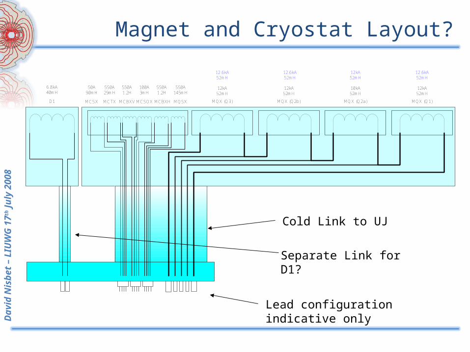
Magnet and Cryostat Layout?
D1 MQX (Q3) MQX (Q2b) MQX (Q2a) MQX (Q1)
6.8kA40mH
10kA52mH
12kA52mH
12kA52mH
12kA52mH
12.6kA52mH
12.6kA52mH
12kA52mH
12.6kA52mH
MCBXV MCBXHMCSOX MQSXMCTX
550A1.2H
550A145mH
550A1.2H
550A29mH
100A3mH
MCSX
50A90mH
Cold Link to UJ
Separate Link for D1?
Lead configuration indicative only
David
Nis
bet
– LIU
WG
17
th J
uly
2008
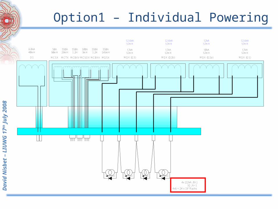
Option1 – Individual Powering
D1 MQX (Q3) MQX (Q2b) MQX (Q2a) MQX (Q1)
6.8kA40mH
10kA52mH
12kA52mH
12kA52mH
12kA52mH
12.6kA52mH
12.6kA52mH
12kA52mH
12.6kA52mH
MCBXV MCBXHMCSOX MQSXMCTX
550A1.2H
550A145mH
550A1.2H
550A29mH
100A3mH
MCSX
50A90mH
4x [12kA, 8V]1Q, N+1
4x6 = 24 x 19" Racks
David
Nis
bet
– LIU
WG
17
th J
uly
2008
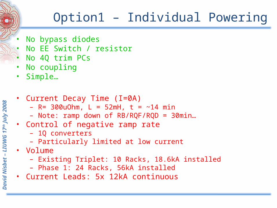
Option1 – Individual Powering
• No bypass diodes• No EE Switch / resistor• No 4Q trim PCs• No coupling• Simple…
• Current Decay Time (I=0A)– R= 300uOhm, L = 52mH, t = ~14 min– Note: ramp down of RB/RQF/RQD = 30min…
• Control of negative ramp rate– 1Q converters– Particularly limited at low current
• Volume – Existing Triplet: 10 Racks, 18.6kA installed– Phase 1: 24 Racks, 56kA installed
• Current Leads: 5x 12kA continuous
David
Nis
bet
– LIU
WG
17
th J
uly
2008
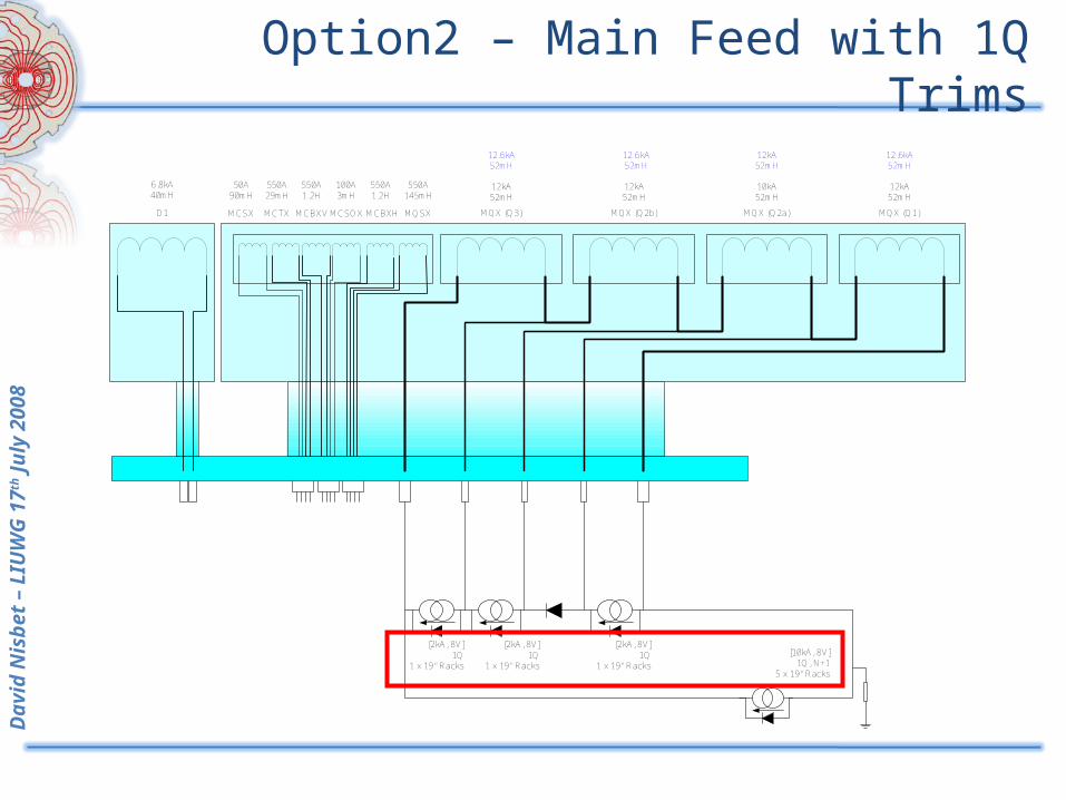
Option2 – Main Feed with 1Q Trims
D1 MQX (Q3) MQX (Q2b) MQX (Q2a) MQX (Q1)
6.8kA40mH
10kA52mH
12kA52mH
12kA52mH
12kA52mH
12.6kA52mH
12.6kA52mH
12kA52mH
12.6kA52mH
MCBXV MCBXHMCSOX MQSXMCTX
550A1.2H
550A145mH
550A1.2H
550A29mH
100A3mH
MCSX
50A90mH
[10kA, 8V]1Q, N+1
5 x 19" Racks
[2kA, 8V]1Q
1 x 19" Racks
[2kA, 8V]1Q
1 x 19" Racks
[2kA, 8V]1Q
1 x 19" Racks
David
Nis
bet
– LIU
WG
17
th J
uly
2008
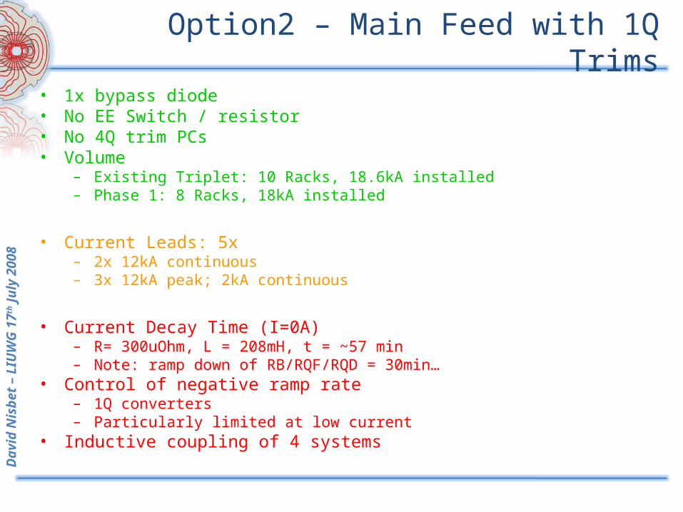
Option2 – Main Feed with 1Q Trims
• 1x bypass diode• No EE Switch / resistor• No 4Q trim PCs• Volume
– Existing Triplet: 10 Racks, 18.6kA installed– Phase 1: 8 Racks, 18kA installed
• Current Leads: 5x– 2x 12kA continuous– 3x 12kA peak; 2kA continuous
• Current Decay Time (I=0A)– R= 300uOhm, L = 208mH, t = ~57 min– Note: ramp down of RB/RQF/RQD = 30min…
• Control of negative ramp rate– 1Q converters– Particularly limited at low current
• Inductive coupling of 4 systems
David
Nis
bet
– LIU
WG
17
th J
uly
2008
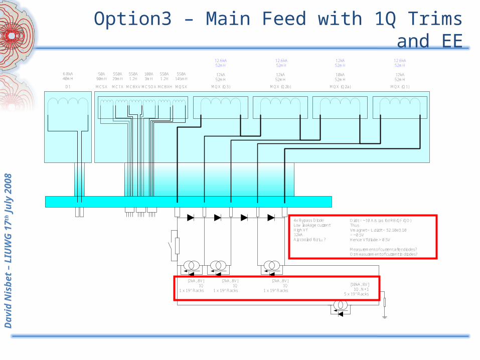
Option3 – Main Feed with 1Q Trims and EE
D1 MQX (Q3) MQX (Q2b) MQX (Q2a) MQX (Q1)
6.8kA40mH
10kA52mH
12kA52mH
12kA52mH
12kA52mH
12.6kA52mH
12.6kA52mH
12kA52mH
12.6kA52mH
MCBXV MCBXHMCSOX MQSXMCTX
550A1.2H
550A145mH
550A1.2H
550A29mH
100A3mH
MCSX
50A90mH
[10kA, 8V]1Q, N+1
5 x 19" Racks
[2kA, 8V]1Q
1 x 19" Racks
[2kA, 8V]1Q
1 x 19" Racks
[2kA, 8V]1Q
1 x 19" Racks
4x Bypass DiodeLow leakage currentHigh Vf12kAAir cooled for tEE ?
Di/dt = ~10 A/s (as for RB/QF/QD)Thus Vmagnet = L.di/dt = 52.10e3.10= ~0.5VHence Vf diode > 0.5V
Measurement of current after diodes?Or measurement of current in diodes?
David
Nis
bet
– LIU
WG
17
th J
uly
2008
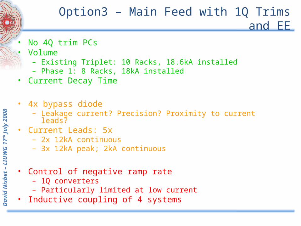
Option3 – Main Feed with 1Q Trims and EE
• No 4Q trim PCs• Volume
– Existing Triplet: 10 Racks, 18.6kA installed– Phase 1: 8 Racks, 18kA installed
• Current Decay Time
• 4x bypass diode– Leakage current? Precision? Proximity to current leads?
• Current Leads: 5x– 2x 12kA continuous– 3x 12kA peak; 2kA continuous
• Control of negative ramp rate– 1Q converters– Particularly limited at low current
• Inductive coupling of 4 systems
David
Nis
bet
– LIU
WG
17
th J
uly
2008
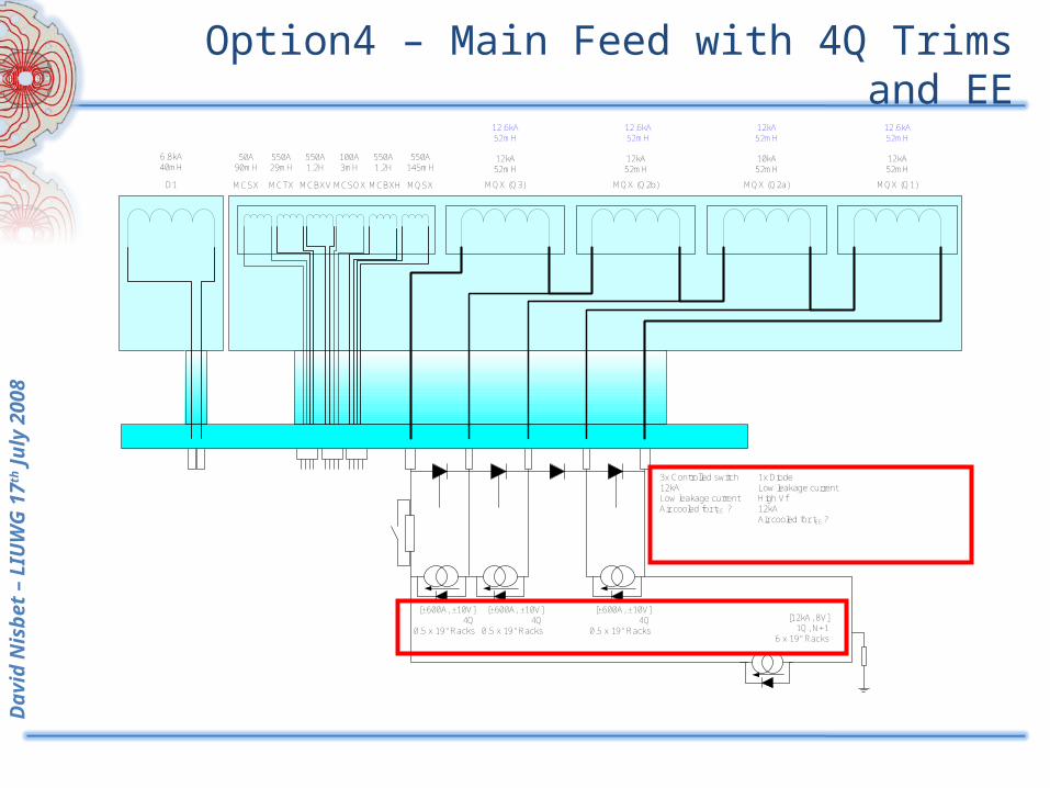
Option4 – Main Feed with 4Q Trims and EE
D1 MQX (Q3) MQX (Q2b) MQX (Q2a) MQX (Q1)
6.8kA40mH
10kA52mH
12kA52mH
12kA52mH
12kA52mH
12.6kA52mH
12.6kA52mH
12kA52mH
12.6kA52mH
MCBXV MCBXHMCSOX MQSXMCTX
550A1.2H
550A145mH
550A1.2H
550A29mH
100A3mH
MCSX
50A90mH
[12kA, 8V]1Q, N+1
6 x 19" Racks
[±600A, ±10V]4Q
0.5 x 19" Racks
3x Controlled switch12kALow leakage currentAir cooled for tEE ?
[±600A, ±10V]4Q
0.5 x 19" Racks
[±600A, ±10V]4Q
0.5 x 19" Racks
1x DiodeLow leakage currentHigh Vf12kAAir cooled for tEE ?
David
Nis
bet
– LIU
WG
17
th J
uly
2008
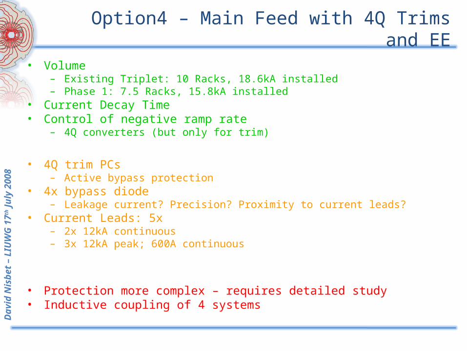
Option4 – Main Feed with 4Q Trims and EE
• Volume – Existing Triplet: 10 Racks, 18.6kA installed– Phase 1: 7.5 Racks, 15.8kA installed
• Current Decay Time• Control of negative ramp rate
– 4Q converters (but only for trim)
• 4Q trim PCs– Active bypass protection
• 4x bypass diode– Leakage current? Precision? Proximity to current leads?
• Current Leads: 5x– 2x 12kA continuous– 3x 12kA peak; 600A continuous
• Protection more complex – requires detailed study• Inductive coupling of 4 systems
David
Nis
bet
– LIU
WG
17
th J
uly
2008
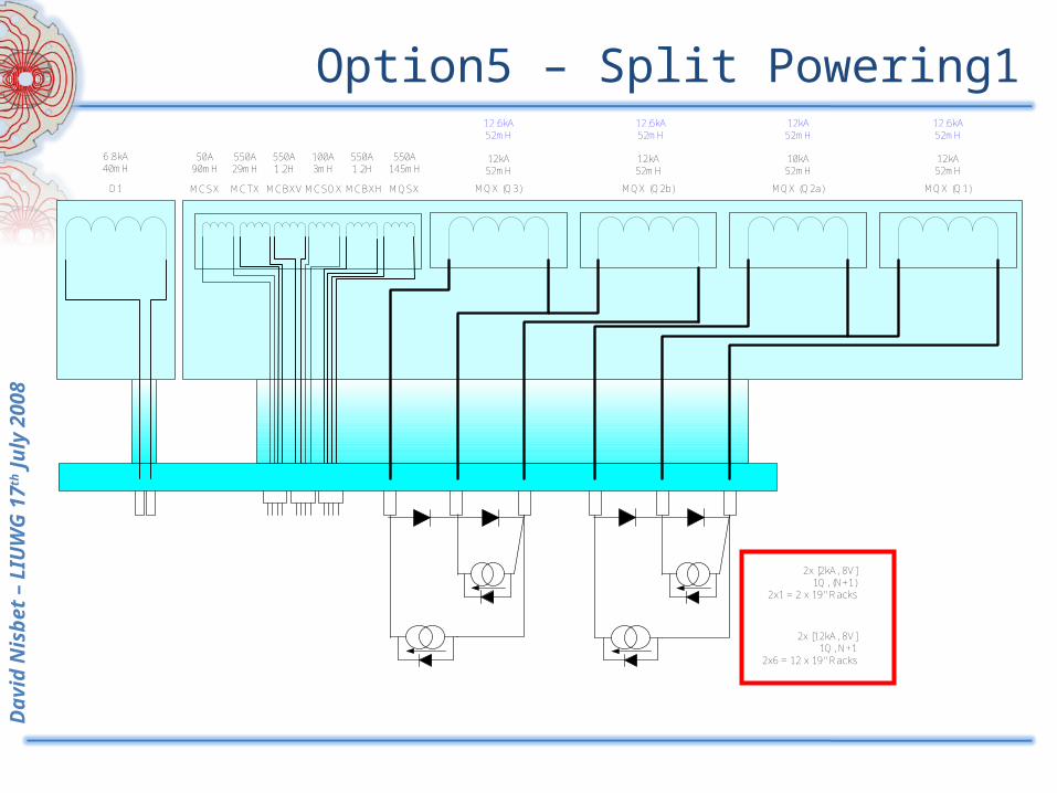
Option5 – Split Powering1
D1 MQX (Q3) MQX (Q2b) MQX (Q2a) MQX (Q1)
6.8kA40mH
10kA52mH
12kA52mH
12kA52mH
12kA52mH
12.6kA52mH
12.6kA52mH
12kA52mH
12.6kA52mH
MCBXV MCBXHMCSOX MQSXMCTX
550A1.2H
550A145mH
550A1.2H
550A29mH
100A3mH
MCSX
50A90mH
2x [12kA, 8V]1Q, N+1
2x6 = 12 x 19" Racks
2x [2kA, 8V]1Q, (N+1)
2x1 = 2 x 19" Racks
David
Nis
bet
– LIU
WG
17
th J
uly
2008
Option5 – Split Powering1
• 1Q trim PCs
• Volume – Existing Triplet: 10 Racks, 18.6kA installed– Phase 1 : 14 Racks, 18kA installed – Potential for N+1 trims and 22kA installed in same volume
• 4x bypass diode– Leakage current? Precision? Proximity to current leads?
• Protection straightforward• Inductive coupling of 2 systems• Current Leads: 6x
– 4x 12kA continuous– 2x 12kA peak; 2kA continuous
• Control of negative ramp rate– 1Q converters– Particularly limited at low current
• Current Decay Time– R= 300uOhm, L = 108mH, t = ~30min– Note: ramp down of RB/RQF/RQD = 30min…
David
Nis
bet
– LIU
WG
17
th J
uly
2008
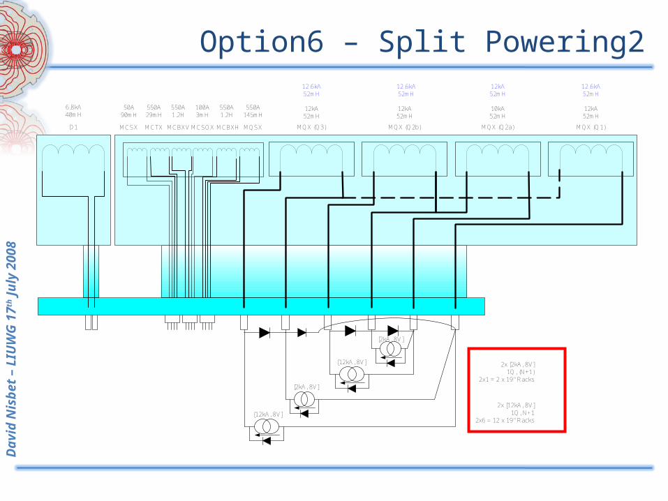
Option6 – Split Powering2
D1 MQX (Q3) MQX (Q2b) MQX (Q2a) MQX (Q1)
6.8kA40mH
10kA52mH
12kA52mH
12kA52mH
12kA52mH
12.6kA52mH
12.6kA52mH
12kA52mH
12.6kA52mH
MCBXV MCBXHMCSOX MQSXMCTX
550A1.2H
550A145mH
550A1.2H
550A29mH
100A3mH
MCSX
50A90mH
2x [12kA, 8V]1Q, N+1
2x6 = 12 x 19" Racks
2x [2kA, 8V]1Q, (N+1)
2x1 = 2 x 19" Racks
[2kA, 8V]
[2kA, 8V]
[12kA, 8V]
[12kA, 8V]
David
Nis
bet
– LIU
WG
17
th J
uly
2008
Option6 – Split Powering2• Current Decay Time• 1Q trim PCs
• Volume – Existing Triplet: 10 Racks, 18.6kA installed– Phase 1 : 14 Racks, 18kA installed – Potential for N+1 trims and 22kA installed in same volume
• 4x bypass diode– Leakage current? Precision? Proximity to current leads?
• Protection straightforward• Inductive coupling of 2 systems• Current Leads: 6x
– 4x 12kA continuous– 2x 12kA peak; 2kA continuous
• Layout of DFB for protection and leads
• Control of negative ramp rate– 1Q converters– Particularly limited at low current
• Current Decay Time– R= 300uOhm, L = 108mH, t = ~30min– Note: ramp down of RB/RQF/RQD = 30min…
• Internal connection from Q1 to Q3
David
Nis
bet
– LIU
WG
17
th J
uly
2008
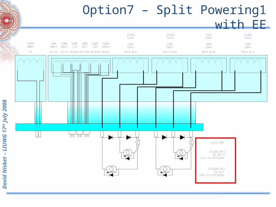
Option7 – Split Powering1 with EE
D1 MQX (Q3) MQX (Q2b) MQX (Q2a) MQX (Q1)
6.8kA40mH
10kA52mH
12kA52mH
12kA52mH
12kA52mH
12.6kA52mH
12.6kA52mH
12kA52mH
12.6kA52mH
MCBXV MCBXHMCSOX MQSXMCTX
550A1.2H
550A145mH
550A1.2H
550A29mH
100A3mH
MCSX
50A90mH
2x [12kA, 8V]1Q, N+1
2x6 = 12 x 19" Racks
2x [2kA, 8V]1Q, (N+1)
2x1 = 2 x 19" Racks
2x EE 12kA
David
Nis
bet
– LIU
WG
17
th J
uly
2008
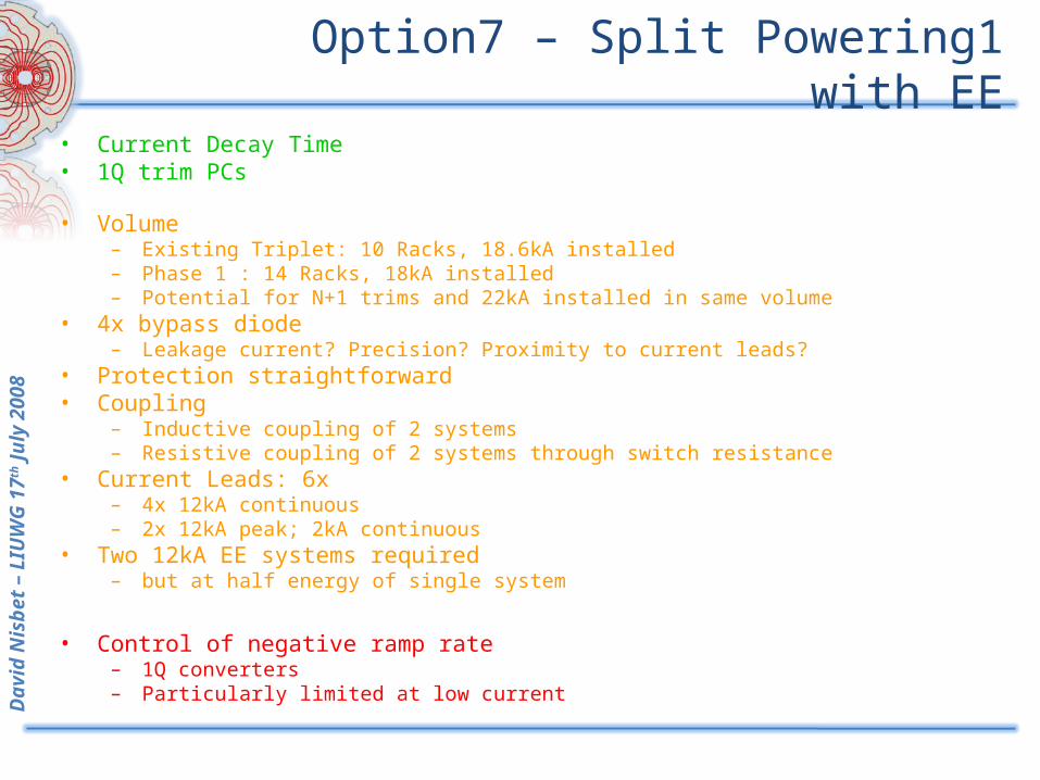
Option7 – Split Powering1 with EE
• Current Decay Time• 1Q trim PCs
• Volume – Existing Triplet: 10 Racks, 18.6kA installed– Phase 1 : 14 Racks, 18kA installed – Potential for N+1 trims and 22kA installed in same volume
• 4x bypass diode– Leakage current? Precision? Proximity to current leads?
• Protection straightforward• Coupling
– Inductive coupling of 2 systems– Resistive coupling of 2 systems through switch resistance
• Current Leads: 6x– 4x 12kA continuous– 2x 12kA peak; 2kA continuous
• Two 12kA EE systems required– but at half energy of single system
• Control of negative ramp rate– 1Q converters– Particularly limited at low current
David
Nis
bet
– LIU
WG
17
th J
uly
2008
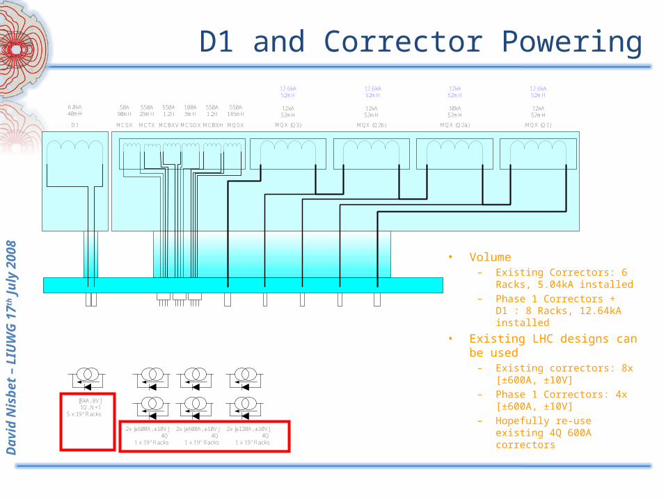
D1 and Corrector Powering
D1 MQX (Q3) MQX (Q2b) MQX (Q2a) MQX (Q1)
6.8kA40mH
10kA52mH
12kA52mH
12kA52mH
12kA52mH
12.6kA52mH
12.6kA52mH
12kA52mH
12.6kA52mH
MCBXV MCBXHMCSOX MQSXMCTX
550A1.2H
550A145mH
550A1.2H
550A29mH
100A3mH
MCSX
50A90mH
[8kA, 8V]1Q, N+1
5 x 19" Racks
2x [±600A, ±10V]4Q
1 x 19" Racks
2x [±600A, ±10V]4Q
1 x 19" Racks
2x [±120A, ±10V]4Q
1 x 19" Racks
• Volume – Existing Correctors: 6
Racks, 5.04kA installed– Phase 1 Correctors +
D1 : 8 Racks, 12.64kA installed
• Existing LHC designs can be used
– Existing correctors: 8x [±600A, ±10V]
– Phase 1 Correctors: 4x [±600A, ±10V]
– Hopefully re-use existing 4Q 600A correctors
David
Nis
bet
– LIU
WG
17
th J
uly
2008
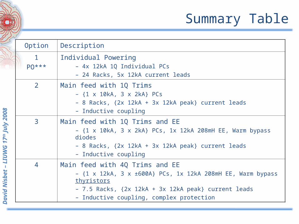
Summary Table
Option Description
1PO***
Individual Powering– 4x 12kA 1Q Individual PCs– 24 Racks, 5x 12kA current leads
2 Main feed with 1Q Trims– {1 x 10kA, 3 x 2kA} PCs– 8 Racks, {2x 12kA + 3x 12kA peak} current leads– Inductive coupling
3 Main feed with 1Q Trims and EE– {1 x 10kA, 3 x 2kA} PCs, 1x 12kA 208mH EE, Warm bypass diodes– 8 Racks, {2x 12kA + 3x 12kA peak} current leads– Inductive coupling
4 Main feed with 4Q Trims and EE– {1 x 12kA, 3 x ±600A} PCs, 1x 12kA 208mH EE, Warm bypass thyristors– 7.5 Racks, {2x 12kA + 3x 12kA peak} current leads– Inductive coupling, complex protection
David
Nis
bet
– LIU
WG
17
th J
uly
2008
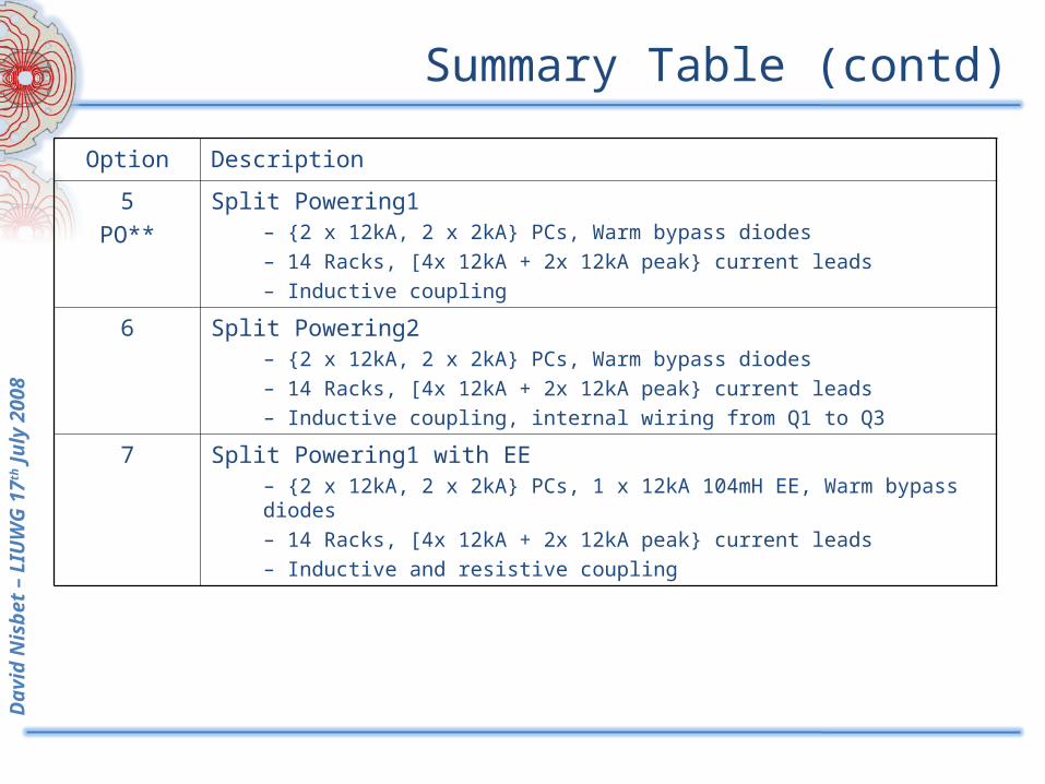
Summary Table (contd)
Option Description
5PO**
Split Powering1– {2 x 12kA, 2 x 2kA} PCs, Warm bypass diodes– 14 Racks, [4x 12kA + 2x 12kA peak} current leads– Inductive coupling
6 Split Powering2– {2 x 12kA, 2 x 2kA} PCs, Warm bypass diodes– 14 Racks, [4x 12kA + 2x 12kA peak} current leads– Inductive coupling, internal wiring from Q1 to Q3
7 Split Powering1 with EE– {2 x 12kA, 2 x 2kA} PCs, 1 x 12kA 104mH EE, Warm bypass diodes– 14 Racks, [4x 12kA + 2x 12kA peak} current leads– Inductive and resistive coupling
David
Nis
bet
– LIU
WG
17
th J
uly
2008
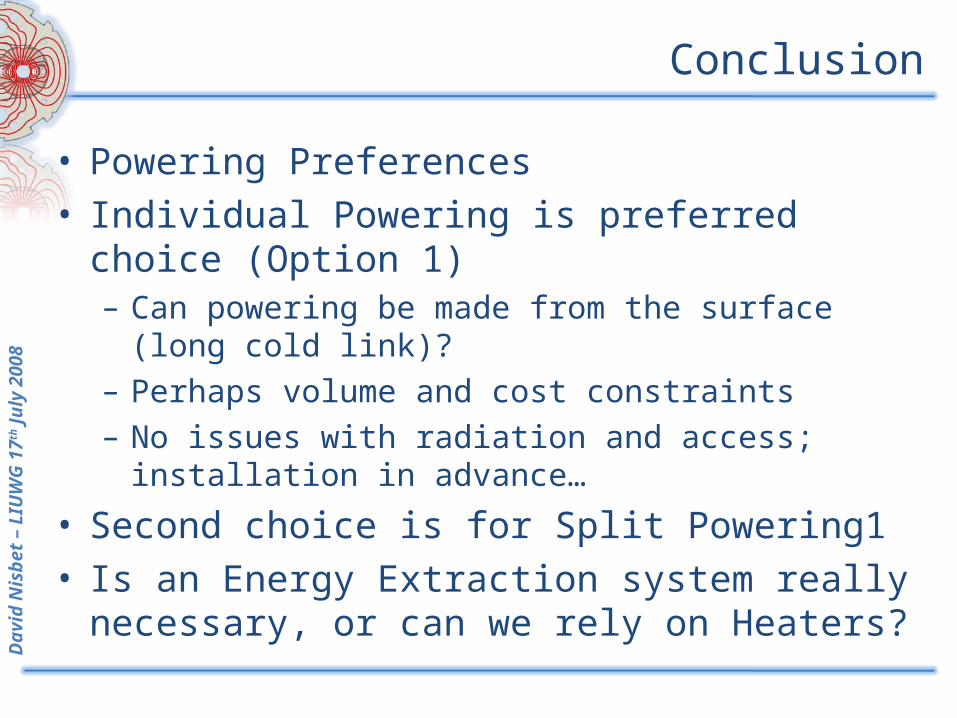
Conclusion
• Powering Preferences• Individual Powering is preferred choice
(Option 1)– Can powering be made from the surface (long
cold link)?– Perhaps volume and cost constraints– No issues with radiation and access; installation
in advance…
• Second choice is for Split Powering1• Is an Energy Extraction system really
necessary, or can we rely on Heaters?