Embed Size (px)
Citation preview
1Uppsala 14/12/11 - Modulators
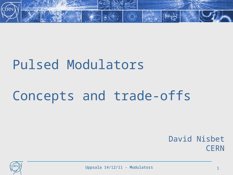
Pulsed Modulators
Concepts and trade-offs
David NisbetCERN

Uppsala 14/12/11 - Modulators 2
Intro
Modulator specification Criteria and concepts
Modulator design Topology selection Commercial v in-house Prototyping
Conclusion

Uppsala 14/12/11 - Modulators 3
RF Powering The RF specification – starting point for modulator
example from ESS requirements
RFQ+DTL 352MHz
Spoke 352MHz
Elliptical 704MHzlow-Beta
Elliptical 704MHzhigh-Beta
Max power/klystron 2.6MW 400kW 700kW 1100kW
Min power/klystron 1.2MW 130kW 65kW 700kW
Beam time 2.9ms
Cavity fill+empty time
0.3ms + 0.3ms
Repetition rate 14Hz
Klystron efficiency 58% <60% <60% 60%
Phase precision 0.5°
Nb of klystrons 4 28 64 120
Max energy of arc 20 J

Uppsala 14/12/11 - Modulators 4
Pulsed v CW
Why a pulsed modulator?
LEP 4MW CW Modulator: 250 m3
(4 MJ/s)
LINAC4 5MW Pulsed Modulator: 7 m3
(20kJ/s)
ESS 4.5MW Pulsed Modulator: ~35 m3
(>200kJ/s)

Uppsala 14/12/11 - Modulators 5
Pulsed Modulators Can be separated into three principle sections
AC/DC ‘Charger’ Energy storage Pulse Forming system

CLIC DB Klystron Modulators 6
Pulsed Modulators Pulse definition
trise
FTS
Vovs
tset tflat tfall
Vkn
Vuns
treset
Time [s]
Vo
ltag
e [
V]
Trep
ideal pulsereal pulse
t_beam + t_fill + t_empty
t_set for LLRF and modulator
t_rise and t_fall
Sources of energy loss:
reset of pulse transformer (if used)

Uppsala 14/12/11 - Modulators 7
Pulsed Modulator Efficiency
Useful flat-top Energy 4.5MW*3.5ms = 15.8kJ
Rise time energy 4.5MW*300μs*1/3= 0.45kJ
Fall time energy* 4.5MW*300μs*1/3= 0.45kJ
Set-up time energy 4.5MW*300μs = 1.35kJ
Pulse efficiency 0.88
Pulse forming system efficiency 0.98
Charger efficiency 0.96
Power efficiency 0.94
Overall Modulator efficiency 80%
Modulator can optimize electrical systems however greatest efficiency savings from RF pulse optimization (eg
klystron efficiency, control overhead, setup time, etc)
*Does not include pulse transformer magnetizing energy
Uppsala 14/12/11 - Modulators 8
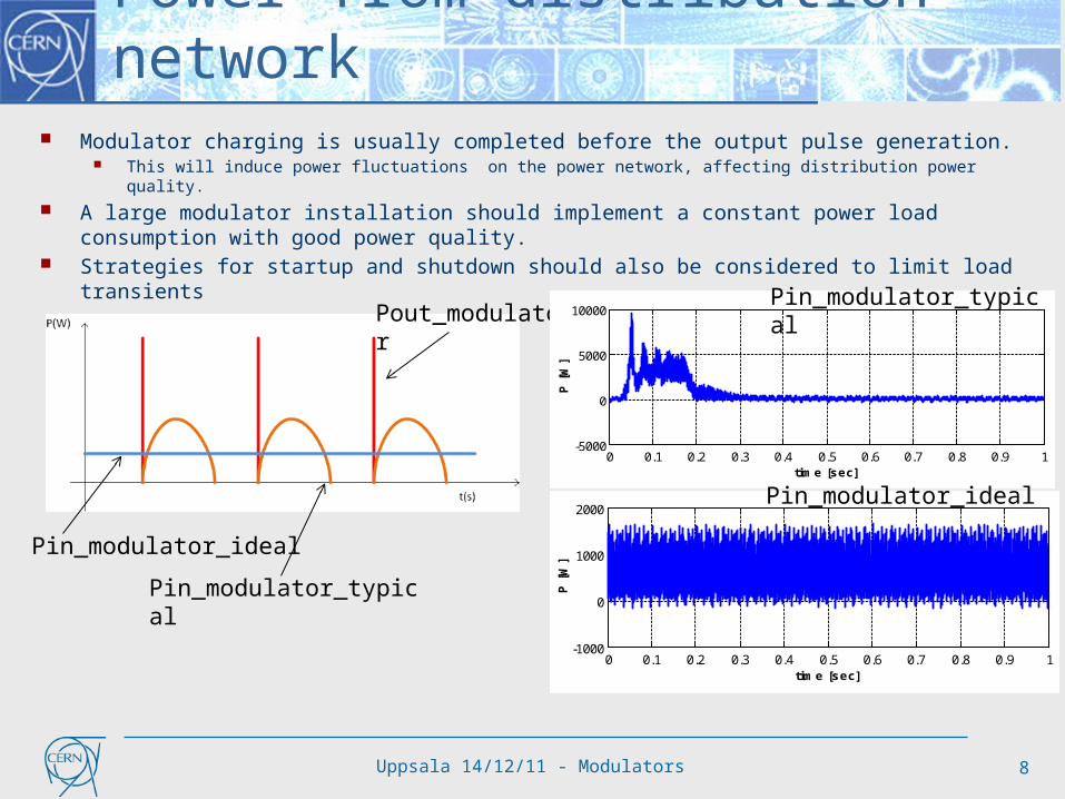
Power from distribution network Modulator charging is usually completed before the output pulse generation.
This will induce power fluctuations on the power network, affecting distribution power quality.
A large modulator installation should implement a constant power load consumption with good power quality.
Strategies for startup and shutdown should also be considered to limit load transients
Pout_modulator
Pin_modulator_typical
Pin_modulator_ideal
0 0.1 0.2 0.3 0.4 0.5 0.6 0.7 0.8 0.9 1-4
-2
0
2
4Vref=690 V / Iref=0.72 A
time [sec]
I a [
A]
0 0.1 0.2 0.3 0.4 0.5 0.6 0.7 0.8 0.9 1-1000
0
1000
2000
time [sec]
P [
W]
0 0.1 0.2 0.3 0.4 0.5 0.6 0.7 0.8 0.9 1-20
-10
0
10
20Vref=690 V / Iref=4.19 A
time [sec]
I a [
A]
0 0.1 0.2 0.3 0.4 0.5 0.6 0.7 0.8 0.9 1-5000
0
5000
10000
time [sec]
P [
W]
Pin_modulator_typical
Pin_modulator_ideal

Uppsala 14/12/11 - Modulators 9
Reliability and availability For large installations, availability is an important
criteria Reliability typically specified as Mean Time Between Failure (MTBF) Repair time defined as Mean Time To Repair (MTTR) Availability as a function of reliability and time to repair:
Modular systems may have lower MTBF but higher availability due to redundant architectures that significantly reduce the MTTR. In many cases, repair can be scheduled for a future date.
Repair time can be significant for high voltage systems unless considered at the design stage (oil, large components, etc).
%MTTRMTBF
MTBFtyAvailabili

Uppsala 14/12/11 - Modulators 10
Modulator specification
1. Maximise charger efficiency and power quality• Objective: better than 95% efficiency with near unity power factor and low
harmonics
2. Minimise rise, fall and settling time• Objective for 3.5ms pulse: less than 750us total for rise, fall and setup
time
3. Maximise operational reliability and availability• Objective: design for 99.8% availability (1hour intervention every 14 days)
4. Design for good pulse-to-pulse voltage reproducibility• Objective: 100ppm (?) from pulsen-1 to pulsen (RF feedback gives long
term performance)
5. Consider integration issues (machine layout, maintenance, etc)

Uppsala 14/12/11 - Modulators 11
Modulator specification
Other important specifications to consider1. Voltage ripple requirement will come from LLRF requirements
Requires to be specified in frequency and amplitude (typically 0.1%)
2. Parallel connection of klystrons Verify sharing/balancing for several klystrons per modulator However already done in SNS using LLRF
3. Operation over a wide power range required Pmax ≥ 10x Pmin Light loading may preclude some topologies (eg bouncer) Connection of systems in parallel will resolve most issues

Uppsala 14/12/11 - Modulators 12
Modulator for RF Powering The following parameters follow from RF specification…
example from ESS requirements
Max power/modulator 4.5MW
Min power/modulator 65kW ?
Nominal voltage 110 kV
Flat top (fill + beam time + empty) 3.5 ms
Rise/fall time 0.3 ms / 0.3ms?
Repetition rate 14Hz
Droop 1% ?
Voltage Ripple (magnitude and frequency) 0.1% above 10kHz ?
Nb of modulators ~110
Max energy delivered to arc <10 J
MTBF 100 000 hrs ?
Availability 99.8 % ?

Uppsala 14/12/11 - Modulators 13
Modulator topology overview
5 topologies highlighted Topologies known to already operate with long pulse applications Future topologies thought to be well adapted to long pulse applications Assessment of some advantages and disadvantages of each topology Some topologies in the market are a mix of more than one concept
I do not claim this list is exhaustive!

Uppsala 14/12/11 - Modulators 14
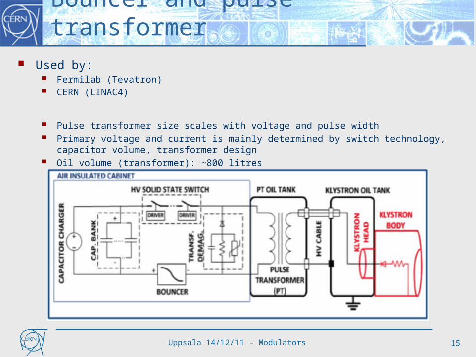
Bouncer and pulse transformer Charger: Classical resonant topology for charging the capacitor. Storage capacitor: The pulsed power is collected by an intermediate storage
capacitor before being transmitted through the switch. Switch: High voltage, high current solid state switch. Pulse transformer: The pulse is generated at high current lower voltage at the
primary side of the pulse transformer. Voltage droop compensation: Voltage compensator for the droop occurring in
the storage capacitor during the pulse discharge.
Uppsala 14/12/11 - Modulators 15
Bouncer and pulse transformer Used by:
Fermilab (Tevatron) CERN (LINAC4)
Pulse transformer size scales with voltage and pulse width Primary voltage and current is mainly determined by switch technology, capacitor volume,
transformer design Oil volume (transformer): ~800 litres

Uppsala 14/12/11 - Modulators 16
Bouncer and pulse transformerAdvantages The power circuit is simple and reliable. All electronic active devices are at medium voltage level No voltage ripple on the flat-top
Disadvantages Large pulse transformer and LC resonant bouncer volume for long
pulses Limited sources for pulse transformer Slow rise and fall times Reverse voltage on the klystron to demagnetize the pulse transformer
limits the duty cycle

Uppsala 14/12/11 - Modulators 17
Direct switch Charger: Very high voltage capacitor charger. Storage capacitor: Capacitors rated for the full voltage. Very high
energy storage. Switch: Full rated voltage slid-state switch. Voltage droop compensation: None. The droop is determined by the
capacitor bank size.

Uppsala 14/12/11 - Modulators 18
Direct switch Other accelerator users
RAL APS
Modulator oil volume: ~2000 litres
Uppsala 14/12/11 - Modulators 19
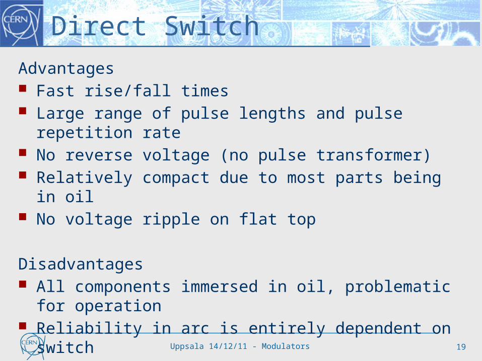
Direct Switch
Advantages Fast rise/fall times Large range of pulse lengths and pulse repetition rate No reverse voltage (no pulse transformer) Relatively compact due to most parts being in oil No voltage ripple on flat top
Disadvantages All components immersed in oil, problematic for operation Reliability in arc is entirely dependent on switch 100kV IGBT switch assembly required (not widely available)

Uppsala 14/12/11 - Modulators 20
Interleaved DC/DC Charger: Distributed across many smaller modules. Connected to multi-
secondary winding interface transformer (also possible to have multiple primaries)
Storage capacitor: Smaller ~1kV rated capacitors distributed across many modules.
Switch: Standard solid-state switch. Voltage droop compensation: Can operate without compensation, or by using a
pulse-modulation technique to obtain desired output characteristics.

Uppsala 14/12/11 - Modulators 21
Interleaved DC/DC Used by
DESY (XFEL)
Oil volume (transformer): ~800 litres
Uppsala 14/12/11 - Modulators 22
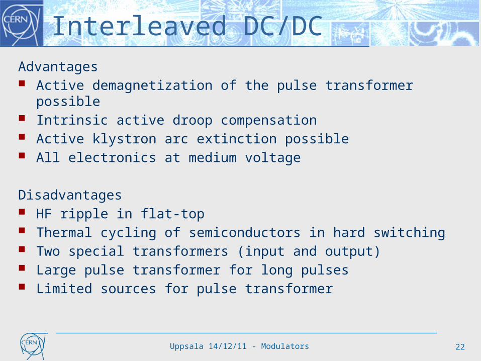
Interleaved DC/DCAdvantages Active demagnetization of the pulse transformer possible Intrinsic active droop compensation Active klystron arc extinction possible All electronics at medium voltage
Disadvantages HF ripple in flat-top Thermal cycling of semiconductors in hard switching Two special transformers (input and output) Large pulse transformer for long pulses Limited sources for pulse transformer

Uppsala 14/12/11 - Modulators 23
Multiple Resonant DC/AC/DC Charger: Distributed across many smaller modules. Storage capacitor: Smaller capacitors distributed across many modules. Switch: Standard solid-state switch. Voltage droop compensation: Flat-top control is inherent in topology

Uppsala 14/12/11 - Modulators 24
Multiple Resonant DC/AC/DC Used by
SNS
Oil volume (transformer): not yet known

Uppsala 14/12/11 - Modulators 25
Multiple Resonant DC/AC/DCAdvantages All electronics at medium voltage Standard semiconductor switches No demagnetization required Intrinsic active droop compensation In klystron arc the resonant circuits become de-tuned Modular
Disadvantages High frequency transformer design difficult Reactive power in H-bridges (some over-rating required) Relies on IGBT soft switching but this is complex Ripple on flat-top – to check if it meets reproducibility requirement

Uppsala 14/12/11 - Modulators 26
Solid State Marx Developed for ILC project Several years of development already
completed
Charger: Normally main charger for all systems.
Storage capacitor: Capacitors distributed across many modules.
Switch: Standard solid-state switch in each module.
Voltage droop compensation: Flat-top control using switch-mode stage – creates a low amplitude ‘sawtooth’ waveform

Uppsala 14/12/11 - Modulators 27
Solid State Marx Used by
SLAC (advanced prototype only)
Oil volume: none
120 kV, 140A, 1.6 ms, 5 Hz

Uppsala 14/12/11 - Modulators 28
Solid State MarxAdvantages No oil or pulse transformer Standard semiconductor switches Intrinsic active droop compensation Low arc energy due to fast turn-off Modular and fault tolerant solution Development almost complete Potential to license design from SLAC?
Disadvantages Fairly complex Electronics are at high voltage (EMC issues) A lot of silicon (cost?) To be validated for (even) longer pulses

Uppsala 14/12/11 - Modulators 29
Cost Comparison See some cost scaling rules presented previously
The cost of each solution should align for industrial production quantities
Resonant topology has additional R&D costs compared to other solutions
Modular systems may benefit additionally from increased quantities
Topology Comment
Bouncer Conventional technology; Pulse transformer;
Direct Switch Simplest solution; Proprietary technology;
Interleaved DC/DC Modular; Conventional semiconductors; Special transformers;
Resonant DC/AC/DC Modular; Conventional semiconductors; Special transformer;
Marx Modular; Conventional semiconductors;

Uppsala 14/12/11 - Modulators 30
‘Spoke’ Modulators Tetrodes and IOTs are being considered for the lower
power spoke cavities, potentially several powered from the same modulator
Modulators for these generally use DC electrical power The power source is essentially the front half of a
pulsed modulator (without pulse forming system) IOT’s now widely used in TV signal transmission Associated CW technology well proven
IOT’s and tetrodes typically operate between 10kV and 50kV
Should be straightforward to find technical solution for powering of tetrodes/IOTs
However important to ensure reliability and availability (and hence modularity) is considered as part of the technical solution
H.V supplye.g. -36 kV / 3.2 A
Grid supplye.g. 150 V / 250 mA
Heater supplye.g. 12V / 25 A
RF OUT
RFIN
+_
- +
+
-
A
P Sanchez, ALBA
Typical IOT Electrical Circuit

Uppsala 14/12/11 - Modulators 31
Modulator R&D As with any project, several phases to consider
Ensure you get what you want!• Project management is a critical aspect to develop appropriate specifications and
make prudent compromises where necessary
Develop specific technologies (eg transformers, inverters, etc)• Requires knowledge of HV, electromagnetics, semiconductors,… • Domain for experts: designers, teams and companies
Validate full scale prototype• Requires general knowledge of complete RF system• Develop system level electronics and software• Initial modulator testing on a passive High Voltage load• Subsequent testing on a klystron (without cavity)• Final validation in compete mock-up

Uppsala 14/12/11 - Modulators 32
In-house v commercial development
In-house development allows facility to confidently maintain and operate equipment for the long term Enables personnel to be highly knowledgeable of technology in
operation Requires investment in people and test facilities
Commercial development is protective of intellectual property and prefers ‘black box’ approach Can be problematic for long term operation of specialized equipment However ability to optimize design and cost for production facilities
LHC R&D and production model Impose topology (you need to know which one…) Allow companies to develop specific (optimized) solutions Competitive tender on validated prototypes All design data made available to buyer to allow long term support

Uppsala 14/12/11 - Modulators 33
Modulator and RF optimization Further activity is encouraged to fully identify the complete
RF system At the design stage, the transfer function for the RF High Power
system should also include a model of the klystron and modulator• Allows certain specifications to be refined and optimized
Typically attention is given to the RF resonant frequency• However the modulator and other components will generate perturbation
(if any) in a lower frequency band Some activity is starting at CERN and SLAC to identify LINAC4 and
CLIC type klystron structures• Every RF system is likely to be different

Uppsala 14/12/11 - Modulators 34
CERN CLIC Modulator Development Challenging project with stringent specs for modulators
Some issues common to other accelerator projects
R&D will be conducted in several centers, coordinated by CERN Intend to evaluate at least 2 different topologies as part of TDR phase
~1600 klystron Modulators required here
2-3 years of R&D at component and sub-assembly level
2-3 years to construct and test full scale prototypes
Regular workshops with collaboration participants to share and direct progress

Uppsala 14/12/11 - Modulators 35
Modulator development efforts The following labs have made, or are making, progress on modulator
technology SLAC (ILC) CERN (CLIC) DESY (XFEL) Los Alamos (SNS)
While each project has specific requirements, there are many common technical challenges
The many large linear collider studies ongoing today would benefit from a coordinated approach to the modulator development
The ESS requirements for long pulse modulators is larger than all previous projects combined
Opportunity to interact with international modulator community Needs an ESS representative/team to follow progress

Uppsala 14/12/11 - Modulators 36
Conclusion The ESS modulator requirements represents a greater financial
investment than the power systems for the entire LHC! The LHC powering was a 10year project from conception to installation Due to good concept and design, excellent availability of power systems
Experience from other large installations, such as SNS, identify the modulator as one of the key reliability/availability drivers
Development time for new systems is significant Both SNS and ILC developments for long pulse modulators have taken >5yrs
The modulators are a significant cost driver in long pulse LINACS It is in the interest of large LINAC projects to have a dedicated modulator team
The proposed strategy for initial construction with a conservative modulator design seems sensible
For subsequent phase, recommend considering 2 (or more) alternative topologies

Uppsala 14/12/11 - Modulators 37
THANKYOU