Embed Size (px)
Citation preview
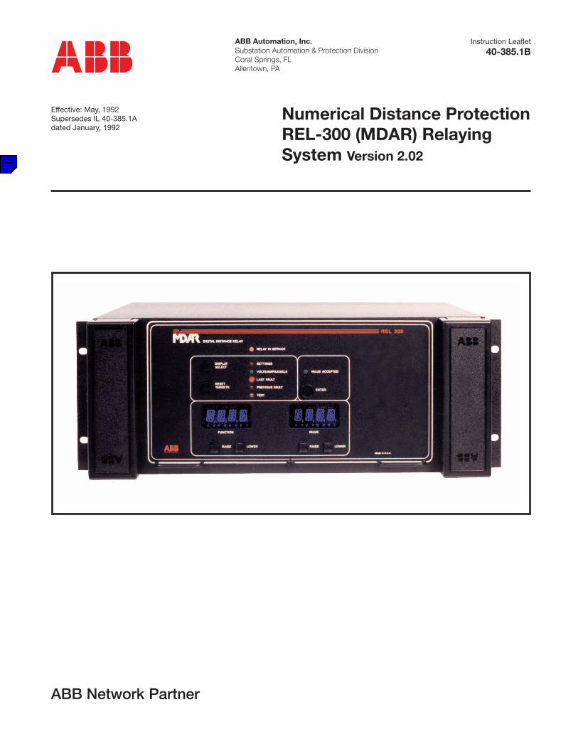
ABB Automation, Inc.Substation Automation & Protection DivisionCoral Springs, FLAllentown, PA
Instruction Leaflet
Effective: May, 1992Supersedes IL 40-385.1Adated January, 1992
Numerical Distance ProtectionREL-300 (MDAR) RelayingSystem Version 2.02
40-385.1B
ABB Network Partner

MDAR REVISION NOTICE
CHANGE SUMMARY:
A CHANGE BAR ( | ) LOCATED IN THE MARGIN REPRESENTS ATECHNICAL CHANGE TO THE PRODUCT.
DATE REV LEVEL PAGES REMOVED PAGES INSERTED
11/91 A v, vi, 1-2, 1-5, 3-2, 3-4, 3-5, 3-7, 3-9, SAME3-10, 3-11, 3-14, 3-15, 4-3, 4-4, 4-11,4-17, 5-1, 5-3, 5-5, 5-6, A-1, A-6, G-8,H-1, H-2, H-5, H-9
1/01/92 A 3-1, H-2, H-7 SAME
1/15/92 A vi, 3-29, J-1, J-2, J-3, J-4, J-5, J-6 SAME
5/92 B 3-2, 3-19, 3-20, 3-21, 3-23, 3-26, 3-2, 3-19, 3-20,5-1, A-1, A-5 thru A-7, B4 thru B-6, 3-21, 3-23, 3-26,C-1,C-4 thru C-6, D-1, D-4 thru D-6, 5-1, A-1, C-1, D-1,E-1, E-7 thru E-12, F-4, F-5, G-1, G-4, E-1, G-1, H-2,thru G-8, H-2, H-6, H-8, H-9, H-14, H-6, H-8, H-9,H-17, H-21 H-14, H-17, H-21

I.L. 40-385.1B
CAUTION
It is recommended that the user of MDAR equipment become acquainted with the information in this instructionleaflet before energizing the system. Failure to do so may result in injury to personnel or damage to the equip-ment, and may affect the equipment warranty. If the MDAR relay system is mounted in a cabinet, the cabinetmust be bolted to the floor, or otherwise secured before MDAR installation, to prevent the system from tippingover.
All integrated circuits used on the modules are sensitive to and can be damaged by the discharge of static elec-tricity. Electrostatic discharge precautions should be observed when handling modules or individualcomponents.
ABB does not assume liability arising out of the application or use of any product or circuit described herein.ABB reserves the right to make changes to any products herein to improve reliability, function or design. Spec-ifications and information herein are subject to change without notice. All possible contingencies which mayarise during installation, operation, or maintenance, and all details and variations of this equipment do not pur-port to be covered by these instructions. If further information is desired by purchaser regarding a particular in-stallation, operation or maintenance of equipment, the local ABB representative should be contacted.
© 1990 by ASEA BROWN BOVERI, ALL RIGHTS RESERVED
ABB does not convey any license under its patent rights nor the rights of others.
(5/92) i

I.L. 40-385.1B
PREFACE
Scope
This manual describes the functions and features of the MDAR Relay System. It is intended primarily for use byengineers and technicians involved in the installation, testing, operation and maintenance of the MDAR system.
Equipment Identification
The MDAR equipment is identified by the Catalog Number on the MDAR chassis nameplate. The Catalog Num-ber can be decoded by using Catalog Number Table 3-1 (see Section 3).
Production Changes
When engineering and production changes are made to the MDAR equipment, a revision notation (SUB #) isreflected on the appropriate schematic diagram, and associated parts information. A summary of all Sub #s forthe particular release is shown below.
Equipment Repair
Repair work is done most satisfactorily at the factory. When returning equipment, carefully pack modules andother units, etc. All equipment should be returned in the original packing containers if possible. Any damage dueto improperly packed items will be charged to the customer.
Document Overview
The circuitry is divided into 6 standard modules and one option module. Section 1 provides the Product Descrip-tion, which includes software functions. Appendices A through G include related module circuit descriptions.Section 2 presents the Specifications. Section 3 presents Non-Pilot applications (see Appendix H for the option-al Pilot System) with related Catalog Numbers for ordering purposes. MDAR Installation, Operation and Main-tenance are described in Section 4, with related Setting Calculations in Section 5. Acceptance Tests for bothNon-Pilot and Pilot System are described in Appendix I. System Diagrams are included in Appendix J.
Contents of Relay System
The MDAR Relay System includes the style numbers, listed below, with appropriate sub numbers (representingrevision levels) for each module. Addenda pages may be included (representing future revisions).
Module Style and Sub Number Addenda
• Backplane 1609C23-4(Sub-Backplane Xfmr) 1498B70-2
• Interconnect 1611C30-2• Option 1608C39-4• Filter 1608C38-5• Microprocessor 1611C14-1• Display 1609C01-3• Power Supply 1608C35-10
Software System
MDAR software version V2.01 is included in this I.L.
Setting Nomenclature Appliques
If this I.L. is included as part of the shipment of an MDAR Relay system, the I.L. will contain setting nomenclatureappliques which can be placed in a convenient location, e.g., inside the two FT-14 covers. The appliques pro-vide a convenient (and complete) set of MDAR “settings” (see Table 4-1 for setting nomenclature). There aretwo appliques which are printed protective sheets (contained in a plastic envelope); the back of the sheets canbe removed thereby exposing a stick-on surface.
ii (5/92)

I.L. 40-385.1B
(5/92) iii
Features Included in Version V2.00The following features are standard for the Non-Pilot MDAR V2.00:
• 3-Zone distance phase and ground relay, with re-versible Zone 3 phase and ground; 4 impedanceunits per zone: 3 phase-to-ground; 1 phase-to-phase.
• Selectable Zone 1 extension• • T1 timer (0 or 2 cycles)
• Independent timers for phase and ground (T2G,T2P, T3G/T3P)
• • Block selection for T2 and T3 timers• Inverse time directional or non-directional (select-
able) overcurrent ground backup logic• Loss of potential supervision (LOP)• Loss of current monitoring (LOI)• Overcurrent supervision• Instantaneous forward directional phase and
ground highset overcurrent trip (ITP and ITG)• Close Into Fault Trip (CIFT)
• • Stub Bus Protection (89b)• Unequal-pole-closing load pickup logic
• • Selectable Loss-of-Load accelerated trip logic(LLT)...setting (YES/NO/FDOG)
• Current change fault detector (∆I)• Voltage change fault detector (∆V)• Last Fault LED now blinks once for a single fault
and twice for more than one fault. When the RE-SET button is depressed, the flashing LED is re-set, and the displayed data is returned to thegreen LED (i.e., Volts/Amps/Angle...meteringmode). MDAR fault data cannot be cleared out ofmemory from the front panel. Fault data can bere-accessed by moving the LED down to the LastFault or Previous Fault.
• Line voltage, current and phase angle monitor.• • Selectable polarizing for directional O/C ground
units (ZSEQ/NSEQ/DUAL)• Programmable Reclose initiation and reclose
block (RB) outputs; Reclose Initiate (RI2) can be
enabled with the selection of:
– 1PR for φG fault
– 2PR for φG or φφ fault
– 3PR for φG or φφ fault or 3φ fault
• Digital Processing
• Fault locator software
• Self-checking software shows error codes
• Breaker trip circuit test
• • Push-to-close test for output contacts
• Software switches for functional tests, e.g., TK(Carry Send Switch), RS1, RS2 and RS12 (CarryReceivers).
• • Trip contact sealed in by trip current; and select-able dropout delay timer, 0/50, (YES/NO)
• • 16 fault records (triggered by TRIP, Z2PU orZ2Z3)
• Real-time clock
• Low voltage pickup setting (LV) for weakfeed log-ic and CIF trip; selection can be made from 40Vrms to 60 Vrms, in 1-volt steps.
• Setting of ZR, range from 0.1 to 7.0
• Setting of XPUD, range from 0.3 to 1.5 per mile orper km
• Setting of FDAT (trip, Z2 trip or Z2Z3 trip)
• Logic for load restrictions
• The reaches of Z1E are based on Zone 1 settingsmultiplied by a factor of 1.25 (e.g., 1.25 x Z1P and1.25 x Z1G).
NOTE: The foregoing (and following) features preceded by two dots (• •) were not included in V1.65.

I.L. 40-385.1B
iv (5/92)
• All features listed as standard for the Non-PilotMDAR V2.00 are included in the Pilot system
• Independent pilot phase and ground distanceunits
• Permissive Overreach Transfer Trip (POTT) /Simplified Unblocking
• Permissive Underreach Transfer Trip (PUTT)• Directional Comparison Blocking Scheme (BLK)• POTT or Simplified Unblocking Weakfeed
• • Instantaneous Forward Directional OvercurrentFunction for High Resistance Ground Fault Sup-
plement to Overreach Pilot, with adjustable timer(from 0 to 15) in 1 cycle steps or Block
• Instantaneous Reverse Directional OvercurrentGround Function
– Carrier Ground Start on Blocking Scheme
– Weakfeed System Application
• • Reclose Block on Breaker Failure (BF) Squelch
• 3-Terminal Line Application
• Weakfeed Trip
Features Included in Version V2.00The following features are standard for the Pilot MDAR V2.00:
Features Included in Version V2.00The following features are optional for the Non-Pilot and the Pilot MDAR V2.00:
• Optional communications attachment
RS232C/PONIINCOM/PONI
• • Optional16 sets of oscillographic data and intermediatetarget data. Each set includes 7 analog graphicinputs and 24 digital intermediate targets with 8samples per cycle. Each analog input contains 1prefault and 7 fault cycles. (Data collection can bestarted by TRIP, Z2PU, Z2Z3 or ∆V ∆I dependingon the setting of OSC.)
• Optional FT-14 switches
• Optional Out-of-Step Block
• Optional Single-Pole-Trip (SPT) logic and out-puts:
– SPT/RI1 on first φGF and 3PT on other faulttypes.
– 3PT/RB if reclosing on a permanent fault.
– 3PT/RB if second phase(s) fault during singlephasing.
– 3PT on a time delay limit (o.35-5.0 sec in 0.05sec steps) if the system fails to reclose (62T).
• Optional OSC Settings (trip or ∆V ∆I)
• Optional TRIP/RI mode selector for:
TTYP SET AT TRIP RI
OFF 3PT NO
1PR 3PT RI2 (φG)
2PR 3PT RI2 (φG, φφG)
3PR 3PT RI2 (φG, Mφ)
SPR SPT (φG) RI1
3PT (Mφ) N0
SR3R SPT (φG) RI1
3PT (Mφ) RI2
SPT = Single Pole Trip
3PT = 3 Pole Trip
RI = Reclose Initiate
RB = Reclose Block
RI2 = 3 Pole Reclose Initiate
RI1 = Single Pole Reclose Initiate
φG = Single Phase-to-Ground Faults
Mφ = Multi-Phase Faults
φφ = 2-Phase Faults

I.L. 40-385.1B
Significant Changes to V2.00 (from V1.65)(for customers who are familiar with Version 1.60 and beyond)
1. 16 fault records, triggered by TRIP or Z2PU or Z2Z3, depending on the FDAT settings (see Section 3.4.16,4.8 and 5.2.2).
2. 16 sets of oscillographic data, triggered by TRIP or Z2PU or Z2Z3 or ∆V ∆I, depending on the OSC setting(see Sections 3.4.19, 4.9 and 5.2.1).
3. Dual (V or I) zero-sequence polarizing unit: see Systems External Connection Drawing, Figure 4-3; ExternalConnection Diagram (Appendix J , 2419F59, Sheet 3 of 4); Section 3.4.11 (Selectable Ground DirectionalUnit (ZSEQ/NSEQ/DUAL); and Acceptance Test, Section 1.1.9, Step 25.
4. The front panel RESET button (now) cannot reset the fault data. It can only reset the flashing LED (see Sec-tion 4.4.3).
5. For the purpose of self-check, the display will now be blocked momentarily every minute (see Sections 1.3.6and 4.4.2).
6. The push-to-close output contacts test simplifies the annual maintenance check (see Section 3.4.15 andAcceptance Test, Section 1.1.13, Step 35).
7. The 3I0 signal (now) is generated by software (Ia+Ib+Ic) and the fourth current transfer is for the DUAL po-
larizing direction application only. The test method and wiring for the 3φ tests are completely different fromthe previous version (refer to Acceptance Tests, Section 1.1.4, Step 12 (3φ test and Figure H-2); and Sec-tion 1.4 (OSB test).
MDAR Version V2.01
1. Sensitivity of NSEQ – Change from I2=0.5 to 312=0.5.
2. LOPB – Add a NOT 52b to the input of AND1F gate to avoid the dropout of AL1 (alarm-1) for the condition of removing the ac voltages before the breaker opening.
3. For POTT system only
a. Connect PLTP & PLTG to carrier keying directly (OR16A & OR18) and modify the signal continuationlogic (TRSL, CIF, AND49A, etc.) to avoid the Send signal dropout time delay (o/150) for the remote for-ward fault.
b. Remove RBSW setting. The reverse block timer logic should always be applied to the POTT system toincrease security on transient due to the unequal pole trip of the adjacent or parallel line.
c. Add a path between 16/0 (RDOG*Ios) and OR41A for weakfeed application to avoyid the false forwardfault trip on the strong feed terminal if the fault is beyond the reach of Zone-3 setting of the weak-feedterminal.
d. Add a path between 16/0 (RDOG*Ios) and OR9A to extend the reach of transient block.
e. For open breaker, omit 52b keying and add echo keying (AND34B).
4. For BLOCKING system only
a. Improve and speed up delta V & I keying.
b. Extend the setting of BLKT timer from 0-32 to 0-98 ms.
c. Remove open breaker (52b) timer (180/0) for Carrier Stop.
(5/92) v

I.L. 40-385.1B
vi (5/92)
5. Use Z1rI (Yes/No) to control the pilot reclose (AND84).
6. Correct the clock setting to avoid the dropout of AL1.
NOTE: CONVERSION FROM MDAR FIRMWARE VERSION V2.00 TO V2.01 CAN BE ACCOMPLISHED ASFOLLOWS:
1. Standard precautions of the static voltage discharges should be observed such as using a grounded wriststrap in order to remove the I.C. from the socket.
2. Remove chips U103 and U104 from the Microprocessor module.
3. Replace chips U103 (605) and U104 (606) into the sockets.
MDAR VERSION 2.02
For BLOCKING system – Add a negated TBM (transient block) logic to the input of AND120 to prevent thepickup of Carrier Stop if the TBM is set. Without the new logic, the Keying signal may be interrupted momentarilyby the Stop due to the logic inside the carrier equipment during the unequal pole clearing for the reverse externalfault.
Trademarks
All terms mentioned in this book that are known to be trademarks or service marks are listed below. In addition, termssuspected of being trademrks or service marks have been appropriately capitalized. ABB Power T&D Company Inc.cannot attest to the accuracy of this information. Use of a term in this book should not be regarded as affecting thevalidity of any trademark or service mark.
IBM and PC are registered trademarks of the International Busoness Machines Corporation.WRELCOM is the registered trademark of the ABB Power T&D Company Inc.INCOM is the registered trademark of the Westinghouse Electric Corporation

I.L. 40-385.1B
(5/92) vii
TABLE OF CONTENTS
PAGE NO.
SECTION 1. PRODUCT DESCRIPTION 1-1
SECTION 2. SPECIFICATIONS 2-1
SECTION 3. APPLICATIONS AND ORDERING INFORMATION 3-1
SECTION 4. INSTALLATION, OPERATION AND MAINTENANCE 4-1
SECTION 5. SETTING CALCULATIONS 5-1
SECTION 6. ACCEPTANCE TESTS 6-1
SECTION 7. MDAR V2.02 INDEX TO NOMENCLATURE 7-1
SYSTEMS DIAGRAMS SD-1

I.L. 40-385.1B
viii (5/92)
FIGURES
FIGURE NO. PAGE
1-1. MDAR Relay Assembly showing FT-14 Switch Covers ............................................................1-6
1-2 Layout of MDAR Modules within Inner and Outer Chassis .......................................................1-7
1-3 INCOM/PONI Communication Interface Device (photo) ...........................................................1-8
1-4 Simplified Block Diagram of MDAR Relay.................................................................................1-9
1-5 MDAR Relay Program Functions ............................................................................................1-10
2-1. CO-2 Curve Characteristics ......................................................................................................2-4
2-2. CO-5 Curve Characteristics ......................................................................................................2-5
2-3. CO-6 Curve Characteristics ......................................................................................................2-6
2-4. CO-7 Curve Characteristics ......................................................................................................2-7
2-5. CO-8 Curve Characteristics ......................................................................................................2-8
2-6. CO-9 Curve Characteristics .....................................................................................................2-9
2-7. CO-11Curve Characteristics ...................................................................................................2-10
2-8. MDAR Outline Drawing ...........................................................................................................2-11
3-1. MDAR Characteristics/R-X Diagram .......................................................................................3-17
3-2. Mho Characteristic for Phase-to-Ground Faults......................................................................3-17
3-3. Mho Characteristics for Three-Phase Faults (No Load Flow) .................................................3-18
3-4. Mho Characteristics for Phase-to-Phase and Two-Phase-to-Ground
Faults (No Load Flow) .............................................................................................................3-18
3-5. MDAR Zone-1 Trip Logic.........................................................................................................3-19
3-6. MDAR Zone-2 Trip Logic.........................................................................................................3-19
3-7. MDAR Zone-3 Trip Logic.........................................................................................................3-20
3-8. MDAR Zone-1 Extension Scheme ..........................................................................................3-20
3-9. Inverse Time Overcurrent Ground Backup Logic ....................................................................3-21
3-10. Loss of Potential Logic ............................................................................................................3-21
3-11. Loss of Potential Logic (System Diagram) ..............................................................................3-22
3-12. AC Current Monitoring Logic ...................................................................................................3-22
3-13. Overcurrent Supervision..........................................................................................................3-23
3-14. Instantaneous Overcurrent Highset Trip Logic........................................................................3-23
3-15. MDAR Close-Into-Fault Trip (CIFT) Logic ...............................................................................3-24
3-16. MDAR Unequal-Pole-Closing Load Pickup Trip Logic ............................................................3-24
3-17. Load Loss Accelerated Trip Logic ...........................................................................................3-25
3-18a. Out-of-Step Block Logic ..........................................................................................................3-25
3-18b. Out-of-Step Block Logic (Blinder Characteristic) .....................................................................3-25
3-19. Reclosing Initiation Logic.........................................................................................................3-26
3-20. Single Pole Trip Logic .............................................................................................................3-26
3-21. POTT/Unblocking Pilot Relay..................................................................................................3-27
3-22. POTT/Unblocking Pilot Trip Logic ...........................................................................................3-27
3-23. Carrier Keying/Receiving Logic in POTT/Unblocking schemes ..............................................3-28
3-24. PUTT Keying Logic .................................................................................................................3-28

I.L. 40-385.1B
(5/92) ix
FIGURE NO. PAGE
3-25. Blocking System Logic............................................................................................................ 3-29
3-26. PLTG supplemented by FDOG............................................................................................... 3-29
3-27. Power Reversed on POTT/Unblocking Schemes ................................................................... 3-30
3-28. Unequal Pole Closing on Fault ............................................................................................... 3-30
3-29. Additional Logic for POTT/Unblocking Schemes on 3-Terminal
Line Application....................................................................................................................... 3-31
3-30. Additional Logic for PUTT Scheme on 3-Terminal
Line Application....................................................................................................................... 3-31
3-31. Weakfeed Application ............................................................................................................. 3-32
3-32. Reversible Zone 3 Phase and Ground (Reverse Block Logic) ............................................... 3-32
4-1. MDAR Backplate....................................................................................................................... 4-7
4-2. MDAR Backplane PC Board Terminals .................................................................................... 4-8
4-3. MDAR System External Connection ......................................................................................... 4-9
6-1. Test Connection for Single-Phase-to-Ground Faults (sheet 1 of 4)........................................ 6-14
6-2. Test Connection for Three-Phase Faults (sheet 2 of 4).......................................................... 6-15
6-3. Test Connection for Phase-to-Phase Faults (sheet 3 of 4)..................................................... 6-16
6-4. Test Connection for Dual Polarizing Ground Directional Unit (sheet 4 of 4)........................... 6-17
6-5. MDAR with Out-of-Step Block Option ..................................................................................... 6-18
SD-1. MDAR System Logic Diagram ............................................................................................... SD-2
SD-2. MDAR System Logic Diagram ............................................................................................... SD-3
SD-3. MDAR System Logic Diagram ............................................................................................... SD-4
SD-4. MDAR System Logic Diagram ............................................................................................... SD-5
SD-5. MDAR Block Diagram............................................................................................................ SD-6

I.L. 40-385.1B
x (5/92)
TABLES
TABLE NO. PAGE
3-1. MDAR Catalog Numbers......................................................................................................... 3-33
3-2 MDAR Accessories ................................................................................................................. 3-34
3-3. Single-Pole-Trip Operating Modes.......................................................................................... 3-34
4-1. Setting Display .................................................................................................. 4-10, 4-11, & 4-12
4-2 Metering Display ..................................................................................................................... 4-13
4-3. Target (Fault Data) Display ..........................................................................................4-14 & 4-15
4-4 Recommended Jumper Positions (V2.XX).............................................................................. 4-16
5-1. Current Transformer Settings.................................................................................................... 5-7
5-2. Reclosing Initiation Mode Programming ................................................................................... 5-7
5-3. Trip Time Constants for Curves ................................................................................................ 5-7
6-1. MDAR Settings (Non-Pilot System) ........................................................................................ 6-19
6-2. Trip Time Constants for CO Curves........................................................................................ 6-19
6-3. Present MDAR Settings (Pilot System)................................................................................... 6-20
6-4. Fault Types Applied to MDAR................................................................................................. 6-21

Relay DivisionsCoral Springs, FL 33065
ABB Power T&D Company Inc.
Printed in U.S.A.
I.L. 40-385.1B305 752-6700
800 523-2620
(5/92)
MDAR RELAY SYSTEM
(V2.02)

MDAR REVISION NOTICE
CHANGE SUMMARY:
A CHANGE BAR ( | ) LOCATED IN THE MARGIN REPRESENTS ATECHNICAL CHANGE TO THE PRODUCT.
DATE REV LEVEL PAGES REMOVED PAGES INSERTED
11/91 A v, vi, 1-2, 1-5, 3-2, 3-4, 3-5, 3-7, 3-9, SAME3-10, 3-11, 3-14, 3-15, 4-3, 4-4, 4-11,4-17, 5-1, 5-3, 5-5, 5-6, A-1, A-6, G-8,H-1, H-2, H-5, H-9
1/01/92 A 3-1, H-2, H-7 SAME
1/15/92 A vi, 3-29, J-1, J-2, J-3, J-4, J-5, J-6 SAME
5/92 B 3-2, 3-19, 3-20, 3-21, 3-23, 3-26, 3-2, 3-19, 3-20,5-1, A-1, A-5 thru A-7, B4 thru B-6, 3-21, 3-23, 3-26,C-1,C-4 thru C-6, D-1, D-4 thru D-6, 5-1, A-1, C-1, D-1,E-1, E-7 thru E-12, F-4, F-5, G-1, G-4, E-1, G-1, H-2,thru G-8, H-2, H-6, H-8, H-9, H-14, H-6, H-8, H-9,H-17, H-21 H-14, H-17, H-21

I.L. 40-385.1B
(5/92) i
It is recommended that the user of MDAR equipment become acquainted with the information in this instructionleaflet before energizing the system. Failure to do so may result in injury to personnel or damage to the equip-ment, and may affect the equipment warranty. If the MDAR relay system is mounted in a cabinet, the cabinetmust be bolted to the floor, or otherwise secured before MDAR installation, to prevent the system from tippingover.
All integrated circuits used on the modules are sensitive to and can be damaged by the discharge of static elec-tricity. Electrostatic discharge precautions should be observed when handling modules or individualcomponents.
ABB does not assume liability arising out of the application or use of any product or circuit described herein.ABB reserves the right to make changes to any products herein to improve reliability, function or design. Spec-ifications and information herein are subject to change without notice. All possible contingencies which mayarise during installation, operation, or maintenance, and all details and variations of this equipment do not pur-port to be covered by these instructions. If further information is desired by purchaser regarding a particular in-stallation, operation or maintenance of equipment, the local ABB representative should be contacted.
© 1990 by ASEA BROWN BOVERI, ALL RIGHTS RESERVED
ABB does not convey any license under its patent rights nor the rights of others.
CAUTION
I.L. 40-385.1B
ii (5/92)
PREFACE
Scope
This manual describes the functions and features of the MDAR Relay System. It is intended primarily for use byengineers and technicians involved in the installation, testing, operation and maintenance of the MDAR system.
Equipment Identification
The MDAR equipment is identified by the Catalog Number on the MDAR chassis nameplate. The Catalog Num-ber can be decoded by using Catalog Number Table 3-1 (see Section 3).
Production Changes
When engineering and production changes are made to the MDAR equipment, a revision notation (SUB #) isreflected on the appropriate schematic diagram, and associated parts information. A summary of all Sub #s forthe particular release is shown below.
Equipment Repair
Repair work is done most satisfactorily at the factory. When returning equipment, carefully pack modules andother units, etc. All equipment should be returned in the original packing containers if possible. Any damage dueto improperly packed items will be charged to the customer.
Document Overview
The circuitry is divided into 6 standard modules and one option module. Section 1 provides the Product Descrip-tion, which includes software functions. Appendices A through G include related module circuit descriptions.Section 2 presents the Specifications. Section 3 presents Non-Pilot applications (see Appendix H for the option-al Pilot System) with related Catalog Numbers for ordering purposes. MDAR Installation, Operation and Main-tenance are described in Section 4, with related Setting Calculations in Section 5. Acceptance Tests for bothNon-Pilot and Pilot System are described in Appendix I. System Diagrams are included in Appendix J.
Contents of Relay System
The MDAR Relay System includes the style numbers, listed below, with appropriate sub numbers (representingrevision levels) for each module. Addenda pages may be included (representing future revisions).
Module Style and Sub Number Addenda
• Backplane 1609C23-4(Sub-Backplane Xfmr) 1498B70-2
• Interconnect 1611C30-2• Option 1608C39-4• Filter 1608C38-5• Microprocessor 1611C14-1• Display 1609C01-3• Power Supply 1608C35-10
Software System
MDAR software version V2.01 is included in this I.L.
Setting Nomenclature Appliques
If this I.L. is included as part of the shipment of an MDAR Relay system, the I.L. will contain setting nomenclatureappliques which can be placed in a convenient location, e.g., inside the two FT-14 covers. The appliques pro-vide a convenient (and complete) set of MDAR “settings” (see Table 4-1 for setting nomenclature). There aretwo appliques which are printed protective sheets (contained in a plastic envelope); the back of the sheets canbe removed thereby exposing a stick-on surface.

I.L. 40-385.1B
(5/92) iii
Features Included in Version V2.00The following features are standard for the Non-Pilot MDAR V2.00:
• 3-Zone distance phase and ground relay, with re-versible Zone 3 phase and ground; 4 impedanceunits per zone: 3 phase-to-ground; 1 phase-to-phase.
• Selectable Zone 1 extension• • T1 timer (0 or 2 cycles)
• Independent timers for phase and ground (T2G,T2P, T3G/T3P)
• • Block selection for T2 and T3 timers• Inverse time directional or non-directional (select-
able) overcurrent ground backup logic• Loss of potential supervision (LOP)• Loss of current monitoring (LOI)• Overcurrent supervision• Instantaneous forward directional phase and
ground highset overcurrent trip (ITP and ITG)• Close Into Fault Trip (CIFT)
• • Stub Bus Protection (89b)• Unequal-pole-closing load pickup logic
• • Selectable Loss-of-Load accelerated trip logic(LLT)...setting (YES/NO/FDOG)
• Current change fault detector (∆I)• Voltage change fault detector (∆V)• Last Fault LED now blinks once for a single fault
and twice for more than one fault. When the RE-SET button is depressed, the flashing LED is re-set, and the displayed data is returned to thegreen LED (i.e., Volts/Amps/Angle...meteringmode). MDAR fault data cannot be cleared out ofmemory from the front panel. Fault data can bere-accessed by moving the LED down to the LastFault or Previous Fault.
• Line voltage, current and phase angle monitor.• • Selectable polarizing for directional O/C ground
units (ZSEQ/NSEQ/DUAL)• Programmable Reclose initiation and reclose
block (RB) outputs; Reclose Initiate (RI2) can be
enabled with the selection of:
– 1PR for φG fault
– 2PR for φG or φφ fault
– 3PR for φG or φφ fault or 3φ fault
• Digital Processing
• Fault locator software
• Self-checking software shows error codes
• Breaker trip circuit test
• • Push-to-close test for output contacts
• Software switches for functional tests, e.g., TK(Carry Send Switch), RS1, RS2 and RS12 (CarryReceivers).
• • Trip contact sealed in by trip current; and select-able dropout delay timer, 0/50, (YES/NO)
• • 16 fault records (triggered by TRIP, Z2PU orZ2Z3)
• Real-time clock
• Low voltage pickup setting (LV) for weakfeed log-ic and CIF trip; selection can be made from 40Vrms to 60 Vrms, in 1-volt steps.
• Setting of ZR, range from 0.1 to 7.0
• Setting of XPUD, range from 0.3 to 1.5 per mile orper km
• Setting of FDAT (trip, Z2 trip or Z2Z3 trip)
• Logic for load restrictions
• The reaches of Z1E are based on Zone 1 settingsmultiplied by a factor of 1.25 (e.g., 1.25 x Z1P and1.25 x Z1G).
NOTE: The foregoing (and following) features preceded by two dots (• •) were not included in V1.65.

I.L. 40-385.1B
iv (5/92)
• All features listed as standard for the Non-PilotMDAR V2.00 are included in the Pilot system
• Independent pilot phase and ground distanceunits
• Permissive Overreach Transfer Trip (POTT) /Simplified Unblocking
• Permissive Underreach Transfer Trip (PUTT)• Directional Comparison Blocking Scheme (BLK)• POTT or Simplified Unblocking Weakfeed
• • Instantaneous Forward Directional OvercurrentFunction for High Resistance Ground Fault Sup-
plement to Overreach Pilot, with adjustable timer(from 0 to 15) in 1 cycle steps or Block
• Instantaneous Reverse Directional OvercurrentGround Function
– Carrier Ground Start on Blocking Scheme
– Weakfeed System Application
• • Reclose Block on Breaker Failure (BF) Squelch
• 3-Terminal Line Application
• Weakfeed Trip
Features Included in Version V2.00The following features are standard for the Pilot MDAR V2.00:
Features Included in Version V2.00The following features are optional for the Non-Pilot and the Pilot MDAR V2.00:
• Optional communications attachment
RS232C/PONIINCOM/PONI
• • Optional16 sets of oscillographic data and intermediatetarget data. Each set includes 7 analog graphicinputs and 24 digital intermediate targets with 8samples per cycle. Each analog input contains 1prefault and 7 fault cycles. (Data collection can bestarted by TRIP, Z2PU, Z2Z3 or ∆V ∆I dependingon the setting of OSC.)
• Optional FT-14 switches
• Optional Out-of-Step Block
• Optional Single-Pole-Trip (SPT) logic and out-puts:
– SPT/RI1 on first φGF and 3PT on other faulttypes.
– 3PT/RB if reclosing on a permanent fault.
– 3PT/RB if second phase(s) fault during singlephasing.
– 3PT on a time delay limit (o.35-5.0 sec in 0.05sec steps) if the system fails to reclose (62T).
• Optional OSC Settings (trip or ∆V ∆I)
• Optional TRIP/RI mode selector for:
TTYP SET AT TRIP RI
OFF 3PT NO
1PR 3PT RI2 (φG)
2PR 3PT RI2 (φG, φφG)
3PR 3PT RI2 (φG, Mφ)
SPR SPT (φG) RI1
3PT (Mφ) N0
SR3R SPT (φG) RI1
3PT (Mφ) RI2
SPT = Single Pole Trip
3PT = 3 Pole Trip
RI = Reclose Initiate
RB = Reclose Block
RI2 = 3 Pole Reclose Initiate
RI1 = Single Pole Reclose Initiate
φG = Single Phase-to-Ground Faults
Mφ = Multi-Phase Faults
φφ = 2-Phase Faults
I.L. 40-385.1B
(5/92) v
Significant Changes to V2.00 (from V1.65)(for customers who are familiar with Version 1.60 and beyond)
1. 16 fault records, triggered by TRIP or Z2PU or Z2Z3, depending on the FDAT settings (see Section 3.4.16,4.8 and 5.2.2).
2. 16 sets of oscillographic data, triggered by TRIP or Z2PU or Z2Z3 or ∆V ∆I, depending on the OSC setting(see Sections 3.4.19, 4.9 and 5.2.1).
3. Dual (V or I) zero-sequence polarizing unit: see Systems External Connection Drawing, Figure 4-3; ExternalConnection Diagram (Appendix J , 2419F59, Sheet 3 of 4); Section 3.4.11 (Selectable Ground DirectionalUnit (ZSEQ/NSEQ/DUAL); and Acceptance Test, Section 1.1.9, Step 25.
4. The front panel RESET button (now) cannot reset the fault data. It can only reset the flashing LED (see Sec-tion 4.4.3).
5. For the purpose of self-check, the display will now be blocked momentarily every minute (see Sections 1.3.6and 4.4.2).
6. The push-to-close output contacts test simplifies the annual maintenance check (see Section 3.4.15 andAcceptance Test, Section 1.1.13, Step 35).
7. The 3I0 signal (now) is generated by software (Ia+Ib+Ic) and the fourth current transfer is for the DUAL po-
larizing direction application only. The test method and wiring for the 3φ tests are completely different fromthe previous version (refer to Acceptance Tests, Section 1.1.4, Step 12 (3φ test and Figure H-2); and Sec-tion 1.4 (OSB test).
MDAR Version V2.01
1. Sensitivity of NSEQ – Change from I2=0.5 to 312=0.5.
2. LOPB – Add a NOT 52b to the input of AND1F gate to avoid the dropout of AL1 (alarm-1) for the condition of removing the ac voltages before the breaker opening.
3. For POTT system only
a. Connect PLTP & PLTG to carrier keying directly (OR16A & OR18) and modify the signal continuationlogic (TRSL, CIF, AND49A, etc.) to avoid the Send signal dropout time delay (o/150) for the remote for-ward fault.
b. Remove RBSW setting. The reverse block timer logic should always be applied to the POTT system toincrease security on transient due to the unequal pole trip of the adjacent or parallel line.
c. Add a path between 16/0 (RDOG*Ios) and OR41A for weakfeed application to avoyid the false forwardfault trip on the strong feed terminal if the fault is beyond the reach of Zone-3 setting of the weak-feedterminal.
d. Add a path between 16/0 (RDOG*Ios) and OR9A to extend the reach of transient block.
e. For open breaker, omit 52b keying and add echo keying (AND34B).
4. For BLOCKING system only
a. Improve and speed up delta V & I keying.
b. Extend the setting of BLKT timer from 0-32 to 0-98 ms.
c. Remove open breaker (52b) timer (180/0) for Carrier Stop.

I.L. 40-385.1B
vi (5/92)
5. Use Z1rI (Yes/No) to control the pilot reclose (AND84).
6. Correct the clock setting to avoid the dropout of AL1.
NOTE: CONVERSION FROM MDAR FIRMWARE VERSION V2.00 TO V2.01 CAN BE ACCOMPLISHED ASFOLLOWS:
1. Standard precautions of the static voltage discharges should be observed such as using a grounded wriststrap in order to remove the I.C. from the socket.
2. Remove chips U103 and U104 from the Microprocessor module.
3. Replace chips U103 (605) and U104 (606) into the sockets.
MDAR VERSION 2.02
For BLOCKING system – Add a negated TBM (transient block) logic to the input of AND120 to prevent thepickup of Carrier Stop if the TBM is set. Without the new logic, the Keying signal may be interrupted momentarilyby the Stop due to the logic inside the carrier equipment during the unequal pole clearing for the reverse externalfault.
Trademarks
All terms mentioned in this book that are known to be trademarks or service marks are listed below. In addition, termssuspected of being trademrks or service marks have been appropriately capitalized. ABB Power T&D Company Inc.cannot attest to the accuracy of this information. Use of a term in this book should not be regarded as affecting thevalidity of any trademark or service mark.
IBM and PC are registered trademarks of the International Busoness Machines Corporation.WRELCOM is the registered trademark of the ABB Power T&D Company Inc.INCOM is the registered trademark of the Westinghouse Electric Corporation

I.L. 40-385.1B
(5/92) vii
TABLE OF CONTENTS
PAGE NO.
SECTION 1. PRODUCT DESCRIPTION 1-1
SECTION 2. SPECIFICATIONS 2-1
SECTION 3. APPLICATIONS AND ORDERING INFORMATION 3-1
SECTION 4. INSTALLATION, OPERATION AND MAINTENANCE 4-1
SECTION 5. SETTING CALCULATIONS 5-1
SECTION 6. ACCEPTANCE TESTS 6-1
SECTION 7. MDAR V2.02 INDEX TO NOMENCLATURE 7-1
SYSTEMS DIAGRAMS SD-1

I.L. 40-385.1B
viii (5/92)
FIGURES
FIGURE NO. PAGE
1-1. MDAR Relay Assembly showing FT-14 Switch Covers ............................................................1-6
1-2 Layout of MDAR Modules within Inner and Outer Chassis .......................................................1-7
1-3 INCOM/PONI Communication Interface Device (photo) ...........................................................1-8
1-4 Simplified Block Diagram of MDAR Relay.................................................................................1-9
1-5 MDAR Relay Program Functions ............................................................................................1-10
2-1. CO-2 Curve Characteristics ......................................................................................................2-4
2-2. CO-5 Curve Characteristics ......................................................................................................2-5
2-3. CO-6 Curve Characteristics ......................................................................................................2-6
2-4. CO-7 Curve Characteristics ......................................................................................................2-7
2-5. CO-8 Curve Characteristics ......................................................................................................2-8
2-6. CO-9 Curve Characteristics .....................................................................................................2-9
2-7. CO-11Curve Characteristics ...................................................................................................2-10
2-8. MDAR Outline Drawing ...........................................................................................................2-11
3-1. MDAR Characteristics/R-X Diagram .......................................................................................3-17
3-2. Mho Characteristic for Phase-to-Ground Faults......................................................................3-17
3-3. Mho Characteristics for Three-Phase Faults (No Load Flow) .................................................3-18
3-4. Mho Characteristics for Phase-to-Phase and Two-Phase-to-Ground
Faults (No Load Flow) .............................................................................................................3-18
3-5. MDAR Zone-1 Trip Logic.........................................................................................................3-19
3-6. MDAR Zone-2 Trip Logic.........................................................................................................3-19
3-7. MDAR Zone-3 Trip Logic.........................................................................................................3-20
3-8. MDAR Zone-1 Extension Scheme ..........................................................................................3-20
3-9. Inverse Time Overcurrent Ground Backup Logic ....................................................................3-21
3-10. Loss of Potential Logic ............................................................................................................3-21
3-11. Loss of Potential Logic (System Diagram) ..............................................................................3-22
3-12. AC Current Monitoring Logic ...................................................................................................3-22
3-13. Overcurrent Supervision..........................................................................................................3-23
3-14. Instantaneous Overcurrent Highset Trip Logic........................................................................3-23
3-15. MDAR Close-Into-Fault Trip (CIFT) Logic ...............................................................................3-24
3-16. MDAR Unequal-Pole-Closing Load Pickup Trip Logic ............................................................3-24
3-17. Load Loss Accelerated Trip Logic ...........................................................................................3-25
3-18a. Out-of-Step Block Logic ..........................................................................................................3-25
3-18b. Out-of-Step Block Logic (Blinder Characteristic) .....................................................................3-25
3-19. Reclosing Initiation Logic.........................................................................................................3-26
3-20. Single Pole Trip Logic .............................................................................................................3-26
3-21. POTT/Unblocking Pilot Relay..................................................................................................3-27
3-22. POTT/Unblocking Pilot Trip Logic ...........................................................................................3-27
3-23. Carrier Keying/Receiving Logic in POTT/Unblocking schemes ..............................................3-28
3-24. PUTT Keying Logic .................................................................................................................3-28

I.L. 40-385.1B
(5/92) ix
FIGURE NO. PAGE
3-25. Blocking System Logic............................................................................................................ 3-29
3-26. PLTG supplemented by FDOG............................................................................................... 3-29
3-27. Power Reversed on POTT/Unblocking Schemes ................................................................... 3-30
3-28. Unequal Pole Closing on Fault ............................................................................................... 3-30
3-29. Additional Logic for POTT/Unblocking Schemes on 3-Terminal
Line Application....................................................................................................................... 3-31
3-30. Additional Logic for PUTT Scheme on 3-Terminal
Line Application....................................................................................................................... 3-31
3-31. Weakfeed Application ............................................................................................................. 3-32
3-32. Reversible Zone 3 Phase and Ground (Reverse Block Logic) ............................................... 3-32
4-1. MDAR Backplate....................................................................................................................... 4-7
4-2. MDAR Backplane PC Board Terminals .................................................................................... 4-8
4-3. MDAR System External Connection ......................................................................................... 4-9
6-1. Test Connection for Single-Phase-to-Ground Faults (sheet 1 of 4)........................................ 6-14
6-2. Test Connection for Three-Phase Faults (sheet 2 of 4).......................................................... 6-15
6-3. Test Connection for Phase-to-Phase Faults (sheet 3 of 4)..................................................... 6-16
6-4. Test Connection for Dual Polarizing Ground Directional Unit (sheet 4 of 4)........................... 6-17
6-5. MDAR with Out-of-Step Block Option ..................................................................................... 6-18
SD-1. MDAR System Logic Diagram ............................................................................................... SD-2
SD-2. MDAR System Logic Diagram ............................................................................................... SD-3
SD-3. MDAR System Logic Diagram ............................................................................................... SD-4
SD-4. MDAR System Logic Diagram ............................................................................................... SD-5
SD-5. MDAR Block Diagram............................................................................................................ SD-6

I.L. 40-385.1B
x (5/92)
TABLES
TABLE NO. PAGE
3-1. MDAR Catalog Numbers......................................................................................................... 3-33
3-2 MDAR Accessories ................................................................................................................. 3-34
3-3. Single-Pole-Trip Operating Modes.......................................................................................... 3-34
4-1. Setting Display .................................................................................................. 4-10, 4-11, & 4-12
4-2 Metering Display ..................................................................................................................... 4-13
4-3. Target (Fault Data) Display ..........................................................................................4-14 & 4-15
4-4 Recommended Jumper Positions (V2.XX).............................................................................. 4-16
5-1. Current Transformer Settings.................................................................................................... 5-7
5-2. Reclosing Initiation Mode Programming ................................................................................... 5-7
5-3. Trip Time Constants for Curves ................................................................................................ 5-7
6-1. MDAR Settings (Non-Pilot System) ........................................................................................ 6-19
6-2. Trip Time Constants for CO Curves........................................................................................ 6-19
6-3. Present MDAR Settings (Pilot System)................................................................................... 6-20
6-4. Fault Types Applied to MDAR................................................................................................. 6-21

I.L. 40-385.1B
(5/92) 1-1
Section 1. PRODUCT DESCRIPTION
1.1 INTRODUCTION
The MDAR relay assembly (Figure 1-1) is a digitaltransmission line protection system, with threezones of distance protection. All measurements andlogic are performed by digital means, using a micro-processor. Self-checking and line monitoring tech-niques are included. MDAR is primarily recommend-ed for application on non-series compensated lines.
The non-pilot MDAR relay assembly is standard (seeSection 3); an optional pilot MDAR relay assembly isalso available (in Section 3).
1.2 MDAR CONSTRUCTION
The standard nomenclature for ABB r elay protectionequipment is as follows:
• Cabinet - contains fixed-racks, swing-racks, oropen racks
• Rack - contains one or more chassis (e.g., theMDAR)
• Chassis - contains several modules (e.g., Micro-processor or Power Supply)
• Module - contains a number of functional circuits(on printed circuit board)
• Circuit - a complete function on a printed circuitboard (e.g., analog-to-digital conversion)
• The MDAR relay assembly consists of an outer-chassis and an inner-chassis which slides into theouter-chassis. The MDAR conforms to the follow-ing dimensions and weight (see also Section 2):
• Height 7" (requires 4 rack units; 1.75" each)
• Width 19"
• Depth 13.6"
• Weight 35 Lbs
All of the relay circuitry, with the exception of the in-put isolation transformers and first-line surge protec-tion, are mounted on the inner chassis, to which thefront panel is attached. The outer chassis has aBackplate, which is a receptacle for all external con-nections, including a communication adaptor (seeFigure 4-1). Two FT-14 switches may be included,as options, in the two peripheral areas of the outerchassis. The FT-14 switches permit convenient andsafe disconnection of trip, ac and dc input circuits,and provide for injection of test signals.
1.3 MDAR MODULES
The inner and outer chassis, together, contain 6standard modules, plus the option module for singlepole trip applications (see Figure 1-2). The Back-plate is connected to the Backplane module (outerchassis). The remaining modules are attached to theinner chassis:
• Interconnect module
• Option module
• Filter module
• Microprocessor module
• Display module
• Power Supply module
Circuit descriptions for each module, may be foundin Appendices A thru G, in accordance with the list inthe Preface to this document (see “Contents of Re-lay System”).
1.3.1 Backplane Module
The Backplane Assembly includes three voltagetransformers, four current transformers, two filterchokes and several surge protection capacitors.
The Backplane Module (see Appendix A) receivesall external connections (with or without the FT-14switch option), and connects directly to the Intercon-nect module, thru plug-in connectors (J11, J12, J13)which provide the connection between outer and in-ner chassis.
The female parts of the connectors are mounted onthe Backplane module, which is part of the outerchassis. The male parts of the connectors aremounted on the Interconnect module, which is partof the inner chassis.
The INCOM® or RS232 PONI1 (see Figure 1-3) ismounted on the Backplate of the outer chassis andis connected to the Backplane module.
1. “INCOM® “stands for INtegratedCOMmunications. The “PONI” acronymstands for Product Operated Network Inter-face.

I.L. 40-385.1B
1-2 (5/92)
1.3.2 Interconnect Module
The Interconnect module (see Appendix B) becomesthe floor of the MDAR inner chassis; it provides elec-trical connections from and to all other modules:from the Backplane (at the rear), to the Filter andPower Supply modules (at left and right, respective-ly), and to the Microprocessor and Display modulesat the front of the inner chassis.
The Interconnect module receives inputs VAN, VB N
,
VCN
, IA, I
B, I
C, IP from the Backplane module and
feeds them to the Filter module. The IP input is used
for zero-sequence dual-polarizing ground currentmeasurement; the input is from the power transform-er neutral ct. Also, seven opto-couplers, on the Inter-connect module, send the following signals to theMicroprocessor module:
• External Reset - resets the front target display.• 52b - used for close-into-fault (CIF) detection,
load loss trip (LLT) and carrier-start and stop con-trol in a pilot system.
• 52a (for single-pole trip option; i.e., for pole dis-agreement).
• Pilot Enable - should be “ON” for the pilot systemoption.
• Receiver #1 (for Pilot option) - carrier receiver fortwo terminal application.
• Receiver #2 (for Pilot option) - second carrier re-ceiver for three-terminal application.
• SBP (89b) for stub bus protection.
1.3.3 Option Module
For 3-pole tripping application, an optional Contactmodule can be plugged into the connector and pro-vide 8 additional programmable output contacts.
1.3.4 Filter Module
The Filter module (see Appendix D) band-limits theseven inputs from the Interconnect module: VAN,
VBN, VCN, IA, IB, IC, IP. These inputs are fed to the
Microprocessor module (analog signal multiplexer).
1.3.5 Microprocessor Module
The Microprocessor module (see Appendix E) in-cludes the following subsystems:
• Microprocessor - Intel 80C196, a 16-bit micro-controller operating with a 10 MHz clock.
• EPROM - Program memory in separate, easily-replaced EPROM chips.
• PROM - Programmable read-only memory.• RAM - Volatile read-write memory, for working
storage.• NOVRAM (EEPROM) - Non-volatile memory for
storing settings and fault-data targets when theMDAR relay is deenergized.
• A/D Converter - The seven inputs from the filtermodule are analog-multiplexed to a single sam-ple/hold circuit. The output of the sample/hold isfed to the Analog-to-Digital Converter through anauto-ranging circuit which shifts gain by a factor ofeight.
• Digital I/O Circuitry - Status inputs from breakerauxiliary contacts (52a and 52b), and ExternalReset signal are interfaced to the microprocessorvia optical isolators (Figure 4-2). The micropro-cessor executes control outputs using dry con-tacts. Output relays (Figure 4-2) are used forbreaker tripping, breaker failure initiation (BFI), re-close initiation (RI), and reclose blocking (RB).General start contact (GS) is provided for startingthe external sequence of events or fault record-ers. Trip and relay-failure alarm contacts are in-cluded. Reed relays in the trip circuits sense tripcoil current flow and feedback target informationto the microprocessor.
1.3.6 Display Module
The Display module has two (four-digit) alphanumer-ic displays for settings, metering fault designationand information. The metering display shows three-phase voltage, current and angle. Fault data, storedin the Microprocessor module, is accessible throughthe front panel display. Fault data includes: pre-faultphase A voltage, current and angle. It also shows thetype of fault, fault voltages, currents, angles and faultlocation. The Display module is attached to the frontpanel (see Figure 1-1); it can be used to access andstore data, and contains 7 LEDs, as follows:
• Relay in Service (ready to use)• Settings (can read or change settings)• Volts/Amps/Angles (can read measuring inputs)• Last Fault (when flashing, indicates new fault in-
formation available)• Previous Fault (when last fault LED flashes twice/
minute, indicates information for the fault preced-ing the last fault)
• Value Accepted (when the Settings LED is also“ON”, a new setting value is accepted; when theTest LED is also “ON”, the output contacts can betested)

I.L. 40-385.1B
(5/92) 1-3
• Test (can verify self-check and perform functionaltest)
The display will be blocked momentarily, everyminute, for the purpose of self-check; this will not af-fect the relay protection function.
1.3.7 Power Supply Module
The Power Supply module (see Appendix G) is avail-able in three ranges:
• 38 - 70 Vdc• 88 - 145 Vdc• 176 - 290 VdcProvides isolation from station battery; includesovercurrent and overvoltage protection. Status mon-itoring and loss-of-power indication are accom-plished via a failure-alarm relay (on the Interconnectmodule). Relay is normally picked up, but the pro-cessor deenergizes it when a problem is found. Totalpower loss also drops-out the relay. Front-panel testpoints provide access to power-supply output voltag-es for test purposes:
• +12 Vdc• -12Vdc• -24 Vdc• + 5 Vdc
1.3.8 Contact Outputs
• 4 make contacts (2 trip, 2 BFI); 8 additional op-tional contacts when single pole trip option isused.
• Single pole reclose initiate (2 Form A)• Three pole reclose initiate (2 Form A)• Reclose block (2 Form A)• General Start (1 Form A)• System failure alarm (1 Form C)• Trip alarm (1Form C; 1 Form A is available if SBP
is not used).
1.4 TEST ACCESSORIES
The MDAR may be tested with two devices:
• Inner Chassis Test Fixture.This device is similar to the outer chassis, and in-cludes a Backplane and Transformer assembly.
• Extender BoardThis device includes two small pc boards with tworibbon cables. The inner chassis can be tested out-side of the outer case by means of the ExtenderBoard.
1.5 FAULT DETECTION SOFTWARE
MDAR fault-detection software operates in twomodes:
• Background mode
• Fault mode
The MDAR relay normally operates in the “Back-ground mode” where it looks for phase current orphase voltage disturbances. Once a phase distur-bance is detected, the relay enters the “Fault mode”.During non-fault operation (in the Backgroundmode), the MDAR Microprocessor (U100) used itsspare time to check its hardware, service the opera-tor panel, and check for a disturbance in voltage orcurrent which indicates a possible fault. If a distur-bance is seen, the programs switch to the Faultmode, for several power cycles or longer, to performphase and ground unit checks for each zone andfunction.
1.5.1 Background Mode
During the background mode, the seven inputs (cur-rents and voltages shown in Figure 1-4) are sampledto test for line faults. These currents and voltagesare sampled and converted into digital quantities andinput to the Microprocessor where all signal process-ing takes place. (MDAR detects faults by digital com-putation; not by analog.) The system continuouslytakes 8 samples per cycle. The components of thesignals which are power system frequency are ex-tracted.
The MDAR software which does the sampling has 8states; these states correspond to the sampling rate(8 samples per cycle). Movement from state to stateis controlled by a timer. The timer is loaded with astate time at the beginning of the state. The code ex-ecuted within a state should be completed before thetimer expires. The software then waits for the timerto time out.
The MDAR relay program functions are included in aflow chart loop (shown in Figure 1-5), which theMicroprocessor repeats 8 times per power cycle.Most functions are performed all of the time, in thebackground mode, as shown. An important detail(not shown in Figure 1-5) is that many of the checksare broken into small parcels, so that the whole com-plement of tasks is performed over a one-cycleperiod (eight passes through the loop). Some of thechecks are performed more than once per cycle.

I.L. 40-385.1B
1-4 (5/92)
The 60 Hz components are extracted from the sam-ples (from each cycle) and converted to voltage andcurrent phasor values using a Fourier notch-filter al-gorithm. An additional dc-offset correction algorithmreduces overreach errors from decaying exponentialtransients. During the process, the sum of squares ofthe inputs are accumulated to provide rms values ofcurrent and voltage. The Fourier coefficients andsums are calculated for computing the phase angles.The sum of squares and the sums of the Fourier co-efficients are updated for each sample, using infor-mation from the previous seven samples, to providea full cycle of data.
1.5.2 Fault Mode and Restricted Fault Tests
Upon entry into the fault mode, the sums of the Fou-rier coefficients and sum of squares from the back-ground mode are stored. New sums are obtained,using fault data, to which offset compensation hasbeen applied.
To speed up tripping for severe faults, restricted faulttesting is implemented. The last half cycle of back-ground mode input samples and the first half cycle offault mode input samples are used to compute thecurrent and voltage vectors and rms values. No dcoffset compensation is performed. High-set instanta-neous overcurrent and Zone 1 distance unit tests areexecuted (see Section 3.2, MDAR Line Measure-ment). This will speed up tripping by as much as onecycle for high current faults.
Instantaneous overcurrent, inverse time overcurrentprotection, and out-of-step blocking are also con-ducted during the fault mode and background mode.
For Zone 2 and Zone 3 faults (see Section 3), imped-ance computation and checking will continuethroughout the specified time delay. The impedancecalculation will be performed once every cycle, in thefault mode and background mode.
1.5.3 Unique Qualities of MDAR
A unique characteristic of the MDAR system is itsphase selection principle. It determines the sum ofpositive and negative sequence currents for eachphase by a novel method which excludes the influ-ence of pre-fault load current. From this information,the fault type can be clearly identified and the actualdistance to the fault can be estimated.
High-resistance ground-fault detection is available inMDAR. Sensitive directional pilot tripping is achievedthrough an FDOG timer (FDGT), which is selectablefrom 0 to 15 cycles or block, on the Microprocessormodule. The pilot distance unit is always active andhas the priority for tripping.
Load-loss tripping entails high-speed, essentially si-multaneous clearing at both terminals of a transmis-sion line for all fault types except three-phase,without the need of a pilot channel.
Any fault location on the protected circuit will be with-in the reach of the zone 1 relays at one or both ter-minals. This causes direct tripping of the localbreaker without the need for any information fromthe remote terminal. The remote terminal recognizesthe loss of load-current in the unfaulted phase(s) asevidence of tripping of the remote breaker. This, cou-pled with Zone 2 distance or directional overcurrentground fault recognition at that terminal, allows im-mediate tripping to take place at that terminal.
1.6 SELF-CHECKING SOFTWARE
MDAR continually monitors its ac input subsystemsusing multiple A/D converter calibration-check in-puts, plus loss-of-potential and loss-of-current moni-toring described. Failures of the converter, or anyproblem in a single ac channel which unbalancesnonfault inputs, trigger alarms. Self-checking soft-ware includes the following functions:
a. Digital Front-end A/D Converter Check
b. Program Memory Check Sum
Immediately upon power-up, the relay does a com-plete ROM (EPROM) checksum of program memo-ry. Afterwards, the MDAR relay continuallycomputes the program memory checksum.
c. Power Up RAM Check
Immediately upon power-up, the relay does a com-plete ROM test of the RAM data memory.
d. Nonvolatile RAM Check
All front-panel-entered constants (settings) arestored in nonvolatile RAM in three identical arrays.These arrays are continuously checked by the pro-gram. If all three array entrees disagree, a nonvola-tile RAM failure is detected.
For failures which do not disable the processor, thecause of the problem can be read on the display.

I.L. 40-385.1B
(5/92) 1-5
The failure modes, represented by their correspond-
ing bits (zero thru 5), are shown in the value field if
the “Test” mode is selected by the “Display Select”
pushbutton.
• Bit 0 External RAM Failure
• Bit 1 EEPROM Warning
• Bit 2 ROM (EPROM) Failure
• Bit 3 EEPROM Failure (Non-Volatile memory)
• Bit 4 Analog Input Circuit Failure
• Bit 5 Microprocessor Failure
All bits are expressed in a HEX byte form. For ex-
ample, if the display shows “Test 1B”, whose binary
representation is 00011011, this means that the re-
lay failed the self-test in the area of External RAM
(bit 0), EEPROM (one-out-of-three failure, bit 1), EE-
PROM (two-out-of-three failure, bit 3) and Analog In-
put Circuit (bit 4). Normally, the test mode should
show “Test 0", meaning that the relay passed the
self-test routines.
1.7 UNIQUE REMOTE COMMUNICATION(WRELCOM) PROGRAM
Two optional types of remote interface can be or-dered.
• RS232C-for single point computer communica-tion.
• INCOM-for local network communication.A special software (WRELCOM) program is provid-ed for obtaining or sending the setting informationto the MDAR. The MDAR front panel shows two faultevents (last and previous), but thru the remote com-munication, 16 fault events and 16 records of inter-mediate target data can be obtained and stored.Each record of the intermediate target data contains8-cycle information (1-prefault and 7 post-fault), with7 analog inputs and 24 digital data (at the samplingrate of 8 per cycle). Refer to WRELCOM manual fordetailed information.


I.L. 40-385.1B
(5/92) 1-7
Figure 1-2. Layout of MDAR Modules Within Inner and Outer Chassis
FT
-14
FIL
TE
R B
D.
PONI BACKPLANE BD.
TRANSFORMERS
OPTION BD.
INTERCONNECT BD.
PROCESSOR BD.
DISPLAY BD.
P/S
& O
UT
PU
T
FT
-14


I.L. 40-385.1B
1-10 (5/92)
Figure 1-5. MDAR Relay Program Functions
ESK00223 dtp
POWER ON
-Initialization-Self-Checks
Mode =Background
START
Sample V and I
dc OffsetCorrection
Compute V and IPhasors Using
Fourier Algorithm
Mode? Fault
Background
Disturbancein V or Ι? Mode =
Fault
Relaying Calculations:Zone 1 and Pilot Zone
Pilot Logic andChannel Control
No Fault for3 Cycles ?
Mode =
Background
- Operator Panel Interface
- Hardware Self-Checks
N
Y
N
Y
Relaying Calculations- Zone 2- Zone 3
- Out-of-Step Blinders- Inst. Overcurrent- Ground Backup- Phase Selector
Checks and Logic- Non-Pilot Trip Logic
- Loss-of-Pot. and Loss-of-Current- Data Communications- Contact Inputs
∆
••
∆

I.L. 40-385.1B
(5/92) 2-1
Section 2. SPECIFICATIONS
2.1 TECHNICAL
Operating Speed(from fault detection 12-14 ms (minimum)to trip contact close 22 ms (typical)-60 Hz)
ac Voltage (VLN) at 60 Hz 70 Vrms(VLN) at 50 Hz 63.5 Vrms
ac Current (In) 1 or 5 A
Rated Frequency 50 or 60 Hz
Maximum Permissible ac Voltage
• Continuous 1.5 x nominal voltage
• 10 Second 2.5 x nominal voltage
Maximum Permissible ac Current
• Continuous 3 x Nominal Current
• 1 Second 100 x Nominal Current
Typical Operating Current 0.5 A
dc Battery Voltages
Nominal Operating Range48/60 Vdc 38 - 70 Vdc110/125 Vdc 88- 145 Vdc220/250 Vdc 176 - 290 Vdc
dc Burdens: Battery 7 W normal30 W tripping
ac Burdens:
Volts per Phase 0.02VA at 70 Vac
Current per Phase 0.15VA at 5 A

I.L. 40-385.1B
2-2 (5/92)
2.2 EXTERNAL CONNECTIONS
Terminal blocks located on the rear of the chassissuitable for #14 square tongue lugs
Wiring to FT-14 switches suitable for #12 wire lugs
2.3 CONTACT DATA
Trip Contacts - make & carry 30 A for 1 second, 10A continuous capability, break 50 watts resistive or25 watts with L/R =.045 seconds
• Non-Trip Contacts
1A Continuous
0.1A Resistive Interrupt Capability
Supports 1000 Vac across open contacts
Contacts also meet IEC - 255-6A, IEC - 255-12, IEC-255-16, BS142-1982.
2.4 MEASUREMENTS
Number of zones: 3 zones are standard (optional pi-lot adds additional zone).
Operating Characteristics: variable mho characteris-tics for all fault types.
2.5 MEASUREMENT UNITS
Three variable mho phase-to-earth units and onevariable mho phase-to-phase impedance unit perzone.
One ground directional (ITG) and one phase direc-tional (ITP) high-set overcurrent unit.
Three-phase non-directional overcurrent units (IL)for load loss trip and CIFT.
One non-directional ground overcurrent unit mediumset (IOM) for ground supervision.
One ground overcurrent unit for LOI monitoring.
One inverse time overcurrent ground unit with COcharacteristics (see Figures 2-1 thru 2-7); selectablenon-directional or directional capability.
One forward set instantaneous directional overcur-rent ground unit. (Pilot-high resistance groundfaults.)
Three under-voltage units (LV) for weakfeed andLOP supervision.
Four current change fault detectors, and three volt-age change fault detectors.
One instantaneous overcurrent unit low set (IOS)
One reverse set instantaneous directional overcur-rent ground unit (Pilot Carrier Start, Weakfeed, Tran-sient Blocking)
2.6 SETTING RANGES
Phase and Ground Distance (Zone 1, 2, 3):
• 0.01-50 ohms in 0.01 ohm steps for 5 A (ct)• 0.05-250 ohms in 0.05 ohm steps for 1 A (ct)Zone Timers - Separate timers for phase andground:
• Zone 1 (No/Yes; 2 cycle delay if Yes is selected)• Zone 2 (0.10 to 2.99 seconds in 0.01 second
steps, Block)• Zone 3 (0.10 to 9.99 seconds in 0.01 second
steps, Block)Forward Directional Ground Timer (FDGT)
• 0 to 15 cycles in 1 cycle steps, BlockOhms per Unit Distance
• 0.300-1.500 in 0.001/DTYP (Km or Mi)Inverse Time Overcurrent Ground Relay:
• Pickup (0.1-0.8) in 0.1 A increments for 1 A (ct).• Pickup (0.5-4.0) in 0.5 A increments for 5A (ct).
Choice of 7 time-curve families (CO-2, 5, 6, 7, 8,9, 11 Characteristics), 63 time curves per family.(See Figures 2-1 thru 2-7.)
• Set for directional or non-directional operation.High set instantaneous directional overcurrent tripunits - phase and ground (IAH, IBH, ICH, IOH).
• 2.0-150 in 0.5 A steps for 5 A (ct)• 0.4-30 in 0.1 A steps for 1 A (ct)
2.7 GROUND, OVERCURRENT AND UNDER-VOLTAGE UNITS
• (Ios, Iom, IL and LV)
Undervoltage level units (LVA, LVB, LVC and CIF)for weakfeed and close-into-fault, from 40 to 60Vrms in 1-volt steps.
Current Units (IAL, IBL, ICL)
• 0.5-10 in 0.5 A steps for 5 A (ct)• 0.1-2 in 0.1 A steps for 1 A (ct)

I.L. 40-385.1B
(5/92) 2-3
Current Change Fault Detectors (∆IA,∆IB,∆IC, and∆I0), no setting required.
Voltage change fault detectors (∆VA, ∆VB and ∆VC)no setting required
Ground Overvoltage Unit 3V0 (no setting required).
2.8 OPTIONAL SINGLE-POLE-TRIP LOGICAND OUTPUTS
• SPT/RI1 on first φGF fault and 3PT on other typesof faults
• 3PT/RB if reclosing on a permanent fault
• 3PT/RB if second phase(s) fault during singlephasing
• 3PT on a selectable time delay limit if the systemfails to reclose (62T)
• TRIP/RI mode selections (TTYP):
SELECT TRIP RI
OFF 3PT NO
1PR 3PT RI2(φG)
2PR 3PT RI2(φG,φφ)
3PR 3PT RI2(φG,φφ,Mφ)
SPR SPT (φG) RI1
3PT (Mφ) NO
SPR/3PR SPT (φG) RI1
3PT (Mφ) RI2
Legend:
SPT - Single Pole Trip3PT - 3 Pole TripRI - Reclose InitiationRB - Reclose BlockRI2 - 3 Pole Reclose InitiateRI1 - Single Pole Reclose InitiateφG - Single Phase to Ground FaultsMφ - Multi-Phase Faultsφφ - 2-Phase Faults
2.9 OPTIONAL OUT-OF-STEP BLOCK
• OSB Override Timer
400-4000 ms in 16 ms steps
• OSB Inner Blinder (RT)
1.0-15.0 ohms in 0.1 ohm steps
NOTE: The RT is a standard setting; it can beused as a load restriction.
• OSB Outer Blinder (RU)
3.0-15.0 ohms in 0.1 ohm steps
2.10 OPTIONAL COMMUNICATION INTERFACE
• RS-232C PONI - for single point computer com-munications
• INCOM/PONI - for local network communications
2.11 CHASSIS DIMENSIONS AND WEIGHT
Height 7" (177.8mm), 4 Rack Units (See Figure 2-8)
Width 19" (482.6mm)
Depth 14" (356mm) including terminal blocks
Weight 35 lb. (16Kg net)
2.12 ENVIRONMENTAL DATA
Ambient Temperature Range
• For Operation -20°C to +60°C
• For Storage -40°C to +80°C
Dielectric Test Voltage 2.8 kV, dc, 1 minute (ANSIC37.90.0, IEC 255-5)
Impulse Withstand Level 5 kV peak, 1.2/50 µsec, 0.5joule (IEC 255-5)
Fast Transient Surge Withstand Capability 4 kV, 5/50 nsec (IEC 801-4); 5kV 10/150 nsec (ANSIC37.90.1)
Oscillatory Surge Withstand Capability 2.5 kV, 1MHz (ANSI C37.90.1, IEC 255-6)
EMI Volts/Meter Withstand 25 MHz-1GHz, 10V/mWithstand (Proposed ANSI C37.90.2).


I.L. 40-385.1B
(5/92) 3-1
Section 3. APPLICATIONS AND ORDERING INFORMATION
3. 1. NON-PILOT SYSTEM
The MDAR non-pilot relay system detects faults inthree zones of distance, phase and ground. Zones 1and 2 are forward set; Zone 3 can be set to forwardor reverse. There is also a separate optional pilotzone (see Section 3.5). The fault locator can be setto indicate fault distance in miles or kilometers.
The R-X Diagram, shown in Figure 3-1, describesthe characteristics available with MDAR. Zone 1phase and ground settings are chosen to providesubstantial coverage of the protected line withoutoverreaching the next bus. A setting of 80% of theline impedance is typical. Faults occurring within thereach of the Zone 1 measurement cause direct trip-ping without regard to any action occurring at the re-mote terminal. Zone 2 settings are chosen to assurethat faults occurring on the next bus are recognized.Settings are chosen (independent of the Zone 1 set-tings), generally to be 120 to 150% of the line imped-ance. Any fault occurring on the protected line will berecognized by this Zone 2 measurement (within thefault resistance and current limitations of the relayingsystem). Zone 2 tripping occurs with time delay (T2)or, where equipped with pilot provisions, at highspeed, subject to the constraints imposed by the pi-lot channel for the particular pilot system selected.The Zone 3 measurement is directional, and may bechosen to respond to forward or reverse faults. Thereverse sensing option is chosen for the blockingsystem where the reverse fault carrier start functionis required. It is also used in conjunction with the T3trip function, chosen to coordinate with adjacent ter-minal Zone 2 timing. The forward sensing option pro-duces time delayed backup to other devices sensingforward faults. Blinder measurements (B1, B2, B3,B4) are available as an option for out-of-step sens-ing. The inner blinder (as a standard function) alsorestricts the trip zone of each of the 3-phase faultmeasuring units.
3. 2. LINE MEASUREMENT TECHNIQUES
Line measurement techniques applied to each zoneinclude:
• Single-Phase-To-Ground fault detection
• 3-Phase fault detection
• Phase-to-Phase fault detection
• Phase-to-Phase-to-Ground fault detection
3.2.1 Single-Phase-to-Ground
Single-phase-to-ground fault detection (see Figure3-2) is accomplished by 3 quadrature polarizedphase units (φA, φB, φC). Equations 1 and 2 (below)are for operating and reference quantity, respective-ly. The unit will produce output when the operatingquantity leads the reference quantity.
(1)
Vector (VQ) (2)
where VXG = VAG, VBG, or VCG
IX = IA, IB or IC
Z1L, Z0L = positive and zero sequence lineimpedance in relay ohms.
ZCG = Zone reach setting in secondaryohms for φGF fault
VQ = quadrature phase voltages, i.e.,VCB, VAC and VBA for φA, φB and φCunits, respectively.
3.2.2 Three-Phase
Three-phase fault detection (see Figure 3-3) is ac-complished by the logic operation of one of the threeground units, plus the 3φF output signal from thefaulted phase selector unit.
However, for a 3-phase fault condition, the computa-tion of the distance units will be:
VXG - IXZCP (3)
and (VQ) (4)
where VXG = VAG, VBG, or VCG
IX = IA, IB or IC
VXG IXZ0L Z1L–
Z1L-----------------------
I0+ ZCG–
I013--- IA IB IC+ +( )=

I.L. 40-385.1B
3-2 (5/92)
ZCP = Zone reach setting (PLTP, Z1PZ2P, and Z3P) in secondary ohmsfor multi-phase faults.
VQ = Quadrature phase voltages, i.e.,VCB, VAC and VBA for φA, φB and φC units, respectively.
3.2.3 Phase-to-Phase
The phase-to-phase unit (see Figure 3-4) respondsto all phase-to-phase faults, and some single-phase-to-ground faults. Equations (5 and 6) are for operat-ing and reference quantity, respectively. They willproduce output when the operating quantity leadsthe reference quantity.
(VAB - IABZCP) (5)
(VCB - ICBZCP) (6)
3.3 MEASUREMENT ZONES
MDAR performs line measurement within 3 zones ofthe transmission line (Zone 1, Zone 2, Zone 3), andone optional pilot zone. When the MDAR functionaldisplay “STYP” is set at “3ZNP”, it will perform the 3-zone non-pilot function.
When the MDAR trips, the trip contacts will besealed-in as along as the trip coil current flow exists.The trip contacts can be delayed dropout (by 50 ms)after the trip current is removed, providing a jumper(JMP4) is connected on the Microprocessor module.
3.3.1 Zone 1 Trip
For Zone 1 phase faults, the Z1P unit will identify thefault and operate. The 3φ fault logic is supervised bythe load restriction logic via AND131C and AND 131(Figure 3-18a) and is also supervised by the select-able OSB, as shown in Figure 3-5. Output of Z1Psatisfies AND-2 and provides a high-speed trip(HST) signal from OR-2 to operate the trip outputtelephone relay. The trip circuit is monitored by aseal-in reed relay (S), which is in-series with eachtrip contact in the tripping circuits. The S relay willpick up if the trip current is higher than 0.5 Amp. Theoperation of the “S” contact will turn-on the breakertrip indicators (with memory), and feeds back to OR-4 to hold the trip relay in operation until the breakertrips and 52a contact opens (not shown in Figure 3-5). The TRSL signal plus the output signal from
AND-2 turns on the Zone 1 phase trip indicator(Z1P). The breaker trip and Zone 1 phase trip indica-tors are memorized. They can be reset by externalRESET voltage or through remote communication.By pushing the RESET pushbutton, the flashing LEDwill be reset, but the fault information will still remainin memory.
The Z1P 3φ trip logic AND-131 is supervised by boththe conventional OSB and the subsequent OSB log-ic when the OSB is set to “YES”, for more security onsome special power system applications. ZIP logicAND-2 is also supervised by the FDOP (Forward Di-rectional Overcurrent Phase unit) when the OSB isset to “YES” for more security on some special pow-er system applications.
Similar operations exist for Zone 1 single-phase-to-ground faults. The Z1G unit sees the fault and oper-ates; the IoM and FDOG units also operate, satisfy-ing AND-3. Tripping occurs via OR-2 with Zone 1ground trip indication Z1G. Logic AND-3 is also su-pervised by the signal of RDOG (reverse directionalovercurrent ground) for security purposes.
The Z1G unit is also supervised by the signal of un-equal-pole-closing and RDOG.
A two-out-of-three “leading phase blocking” logic isincluded for solving the overreach problem of thesingle-phase ground distance units, which may re-spond to a φφG fault.
The high-speed trip (HST) signal also is connectedto the reclosing initiation logic.
Either or both Zone 1 phase and Zone 1 groundfunction(s) can be disabled by setting the Z1P and/or Z1G to the position. Zone 1 trip can be delayed bysetting T1 = YES. The delay time is 2 cycles for anon-pilot 3PT backup, with another system operat-ing in SPT mode.
3.3.2 Zone 2 Trip
For Zone 2 phase faults, the Z2P unit will see thefaults and operate the Zone 2 phase timer (T2P).The Z2P output plus the T2P timer output satisfyAND-18, as shown in Figure 3-6. The AND-18 outputprovides time delay trip signal TDT via OR-3. SignalTDT picks up OR-4 (Figure 3-5) and operates the triprelay. The tripping and targeting are similar as

I.L. 40-385.1B
(5/92) 3-3
described in Zone 1 trip except for Zone 2 phasetime delay trip indicator (Z2P).
Similar operation occurs for Zone 2 single-phase-to-ground faults. The Z2G unit sees the fault and oper-ates. This, plus the operation of the IoM, FDOG andT2G satisfy AND-19, and provide the TDT signal viaOR-3 with Zone 2 ground time delay trip indicator(Z2G).
The single-phase ground distance units may re-spond to a φφG fault. The output of the Z2G unit plusthe operation of the φφ selection will trip the Z2P viaOR-157, T2P and AND-18. Leading phase blockingis unnecessary for an overreach Zone device.
The TDT signal can be connected to the reclosingblock logic. The settings for Zone 2 timers (phaseand ground units) are independent, as follows:
• T2P (Zone 2 phase)
• T2G (Zone 2 ground)
The range of the timers is as follows:
• T2P and T2G (0.1 to 2.99 seconds or Block)
Either or both Zone 2 phase and Zone 2 groundfunction(s) can be disabled by setting Z2P and/orZ2G to the BLK position.
3.3.3 Zone 3 Trip
For Zone 3 phase faults, the Z3P (forward or reverselooking, depending on the Z3FR setting) unit willidentify the faults and operate the Zone 3 phase tim-er T3P. The Z3P output plus the T3P timer outputsatisfy AND-20 (as shown in Figure 3-7). The AND-20 output provides time delay trip signal (TDT) viaOR-3. Signal TDT picks up OR-4 (Figure 3-5) andoperates the trip relay. The tripping and targeting aresimilar to Zone 1 trip, except for the Zone 3 phasetime delay trip indicator (Z3P).
For Zone 3 single-phase-to-ground faults, Z3G iden-tifies the fault and operates. This, plus the operationof the IOM, satisfies AND-7; the TDT signal thentrips via OR-3 with Zone 3 ground time delay trip in-dicator Z3G. The TDT signal can be connected tothe reclosing block logic. For security, the Z3G unitis also supervised by the signal of FDOG when it isset for forward looking (or by the signal of RDOGwhen it is set for reverse looking) via logic OR-171B,AND-171C or AND 171D (as shown in Figure 3-7).
A similar operation for φφG faults (shown in Zone 2),is applied to Zone 3, through OR-170, T3P and AND-20 gates.
The settings for Zone 3 timers (phase and groundunits) are independent, as follows:
• T3P (Zone 3 phase)
• T3G (Zone 3 ground)
The range of the timers is as follows:
• T3P and T3G (0.1 to 9.99 seconds or Block)
Either or both Zone 3 phase and Zone 3 groundfunction(s) can be disabled by setting Z3P and/orZ3G to the BLK position.
3.3.4 Zone 1 Extension
This scheme provides a higher speed operation onend zone faults without the application of pilot chan-nel.
If the MDAR functional display “STYP” is set on Z1Eposition, the Z1P/Z1G unit will provide two outputs:one is overreach which is set at 1.25 x Z1 reach bythe microprocessor, and one is the normal Z1 reach.A single shot instantaneous reclosing device shouldbe used when applying this scheme. The targetsZ1P/Z1G will indicate either Z1 trip and/or Z1E tripoperations. The other functions (e.g., Z2T, Z3T, actrouble monitoring, overcurrent supervision, IT, CIF,unequal-pole closing load pickup control, load-lossacceleration trip, etc.) would remain the same as inthe basic scheme (3ZNP).
For a remote internal fault (refer to Figure 3-8), eitherZ1P or Z1G will see the fault since they are set tooverreach. High speed trip will be performed via thenormal Z1T path (Figure 3-5), i.e., AND-2 (or AND-3), OR-2. HST signal operates the instantaneous re-closing scheme. The breaker recloses and staysclosed if the fault is automatically cleared.
Target Z1P and/or Z1G will be displayed. Once thebreaker trip circuit carries current, it operates the log-ic OR-5 (not shown), produces output signal TRSL,and satisfies logic AND-26 for 5000 ms (Figure 3-8).The output signal of AND-26 will trigger the Z1P/Z1Greach circuit, constricting their reaches back to thenormal Zone 1 for 5000 ms. During the reach con-stricting periods, if the breaker is reclosed on a Zone1 permanent fault, it will retrip again. If the breaker is
I.L. 40-385.1B
3-4 (5/92)
reclosed on an end-zone permanent fault, the nor-mal Z2T will take place.
For a remote external fault, either Z1P or Z1G willsee the fault since they are set to overreach. Highspeed trip will be performed. HST signal operatesthe instantaneous reclosing scheme. The breakerrecloses and stays closed if the fault has been isolat-ed by the adjacent line breaker. However, if theadjacent line breaker fails to trip, the normal remoteback up will take place.
NOTE: The reaches of Z1E are based on theZone 1 settings multiplied by a factor of1.25 (e.g., 1.25 x Z1P and 1.25 x Z1G).
3.4 MDAR NON-PILOT FEATURES
The following features are standard with theNon-Pilot MDAR
3.4.1 3-Zone Distance Phase and Ground Relaywith Reversible Zone 3 Phase and Ground
There are four impedance units per zone: onephase-to-phase unit and three phase-to-groundunits. Zone 3 can be set to forward or reverse for car-rier keying or back-up tripping in pilot system appli-cations.
3.4.2 Directional or Non-Directional InverseTime Overcurrent Ground Backup Logic
The overcurrent ground backup (GB) unit is to sup-plement the distance ground protection on high re-sistance ground faults. It provides an inverse timecharacteristic which is similar to the conventional COcharacteristics (see Figure 2-1 thru 2-7). The timecurves can be selected by the GBCV Setting. Thetime dial is set by the “GTC” value. The unit can beselected as directional by using the “GDIR” (YES)setting and the pickup value by GBPU. The direc-tional GB function uses the torque control approach,as indicated in Figure 3-9. The GB function can bedisabled by setting the GBCV to the OUT position.
The directional unit is determined by the setting of“DIRU” which can be set to zero sequence voltage(ZSEQ), dual (DUAL, zero sequence voltage and/orzero sequence current) or negative sequence(NSEQ, negative sequence voltage and negative se-quence current) for polarization (see 3.4.11, Select-able Ground Directional Unit, ZSEQ / NSEQ /DUAL).
3.4.3 Loss of Potential Supervision (LOP)
The ac voltage monitoring circuit is called loss-of-po-tential circuit. In order to prevent undesirable trippingdue to the distance unit(s) pickup on loss-of-poten-tial, the following logic is used:
• (VAN or VBN or VCN <7Vac) or (3Vo>7Vac) andnot ∆I or not (3IO>IOS)
This means that the LOPB will be set if any one ofthe voltages is below 7Vac (without ∆I), or if the sys-tem detects 3Vo without 3Io (or 3IO > IOS) as shown
in Figure 3-10. The (loss-of-potential condition satis-fies AND-1; output signal of AND-1 starts the 8/500ms timer. The timer output will satisfy AND-1C ifthere is no output from AND-1B. Output signal ofAND-1C will block all the distance unit (Z) trippingpaths via AND-2, AND-3, AND-4, AND-5, AND-6,AND-172 (also blocks AND-191 and AND-187 for Pi-lot Systems), if LOPB is set at YES. Although all dis-tance units are blocked for tripping, the groundbackup (GB) and high-set overcurrent units (ITP andITG) are operative and converted to non-directionalautomatically. The LOPB blocking function can bedisabled by setting the LOPB functional display atNO position. The output of the LOP timer will de-en-ergize the alarm 1 (AL1) relay and cause the failurealarm.
When applying the LOPB to YES, it is the intent toblock all distance units from tripping, should LOPcondition exist. However, under a special systemcondition (refer to Figure 3-11), both circuits are en-ergized without load current; with no source at termi-nal B, fault at F where F is near terminal A, Zone 2relay at terminal B will be blocked by LOP, and mayfail to trip. This is because the relay at B sees no cur-rent, and a low voltage condition exists before circuitbreaker A opens. Another special system conditioninvolves two parallel lines with two symmetricalsources at both ends. For an evolving flashoverfault, at a point equidistant from both terminals, theconventional LOPB logic will block trip, because thefirst external fault generates “3V0 and not 3I0“on theprotected line. Logic AND-1A, 1B, -1C, and -1E 150/0, 0/3500 ms timers circuit (in Figure 3-10) are forsolving these problems. This logic unblocks theLOPB circuit and provides a 3500 ms trip window forthe distance units to trip if the fault current is detect-
I.L. 40-385.1B
(5/92) 3-5
ed within 150 ms after LOP has been set up. Thislogic has no effect on the conditions:
• if ∆I signal occurs ahead of LOP, or
• if LOP and ∆I signals occur simultaneously
NOTE: The LOPB setting detects a blown fusecondition.
The distance units are designed to beblocked under the loss-of-potential con-dition, but the high set (ITP and ITG) andground backup (GB) are functional andconverted to non-directional automati-cally (see also 3.4.6).
3.4.4 Loss of Current Monitoring (LOI)
The ac current monitoring circuit uses IoM (and notVo) as criterion, as shown in Figure 3-12. Under ctshort circuit or open circuit condition, IoM (and notVo) satisfies AND-23; the output signal of AND-23starts the 500/500 ms timer. The timer output turns“ON” the non-memory LOI indicator, which is shownin the Metering mode, and drops out the AL1 relay(Failure Alarm). If the LOI condition exists and LOIBis set at YES, the trip will be blocked after the 500 mstimer times out.
3.4.5 Overcurrent Supervision
For MDAR, as shown in Figure 3-13, the distanceunits do not require overcurrent supervision; be-cause the relay normally operates in a backgroundmode, they will not start the Zone 1 and pilot imped-ance computation until a phase current or a phasevoltage disturbance is detected. This approach canminimize the load problem when setting the phaseovercurrent units. However, the 3-phase units aresupervised by the load restriction logic, and the 21BIunit is restricted by the setting of IL units, conse-
quently, the 3-phase units are supervised by the ILsetting. For increasing the security. The applicationof LOPB supervision function is also normally rec-ommended.
For coordination purposes the ground trip units(Z1G, Z2G, Z3G, PLTG, and FDOG) are supervisedby the medium set ground overcurrent unit (IoM).The Ios setting and RDOG are used for carrier sendin a Pilot Blocking system.
3.4.6 Instantaneous Forward Directional Over-current Trip/Highset Trip Logic
The instantaneous overcurrent units (IAH, IBH, ICHand IOH) are normally set forward directional andhigh to detect those faults which occur in the Zone 1area, therefore, their tripping will occur via OR-2 forHST, as shown in Figure 3-14. These high set tripfunctions can be disabled by setting the ITP (phase)and/or ITG (ground) to the OUT position. The direc-tional unit (ITP and ITG) will be automatically con-verted to non-directional protection if the LOPcondition occurs and the setting of LOPB = YES.
3.4.7 Close-Into-Fault Trip (CIFT) andStub-Bus Protection (SBP)
There are three low voltage units (LVA, LVB andLVC) in MDAR. Each unit senses the phase voltagecondition in the background mode. The unit can beset from 40 to 60 volts, in 1.0 volt steps. For anyphase voltage below its preset value, the LV logicwill produce a logic “1” output signal. The low voltageunits are used in CIFT and weakfeed logic in MDAR.
In order to supplement distance unit operation, whenthe circuit breaker is closed into a fault and line sidepotential is used, the Close-Into-Fault Trip (CIFT)circuit operates as shown in Figure 3-15. It includeslogic AND-22, OR-3 and 100/180 ms and 16/0 mstimers. If any overcurrent unit (IAL, IBL, ICL or IOM)operates OR-11, at the same time as one of thephase voltages (VA, VB,VC) is below the preset lev-el of the LV units. Then logic AND-22 is satisfied andproduces a trip signal (for 180 ms) after circuit break-er closes (52b contact opens). Tripping will be viaOR-3, with RB and CIF targets.
The stub bus protection feature protects a line termi-nal with the potential device on the line-side. Withthe line disconnect switch open, the distance unitswill lose their reference voltage, and may not func-tion correctly when a fault occurs on the short part ofthe bus between the ct location and the opened dis-connect switch. The logic for stub bus protection isindependent of the operation of the circuit breaker(s)and the line voltage condition. Also, it requires theinformation from the disconnect switch (89b). Thestub bus protection logic, as shown in Figure 3-15,includes the contact convertor for the 89b switch andAND-22E and OR-22B logic.

I.L. 40-385.1B
3-6 (5/92)
The application of “close-into-fault” and “stub-busprotection” are selected by setting the value field ofCIF to CIFT/STUB/BOTH/NO.
3.4.8 Unequal-Pole-Closing Load Pickup Logic
The ground units may pick up on a condition of loadpickup with unequal breaker pole closing. The highspeed ground units (Z1G, FDOG and RDOG andPLTG) should be supervised under this condition.This can be achieved (as shown in Figure 3-16) byinserting a 0/20 ms timer (controlled by the 52b sig-nal) to supervise the Z1G trip AND-3. It should benoted that the 20 ms time delay will have no effect ona normal fault clearing.
3.4.9 Selectable Loss-of-Load Accelerated TripLogic (LLT)
The load-loss speedup Zone 2 trip logic senses re-mote 3-pole clearing on all faults except 3φF to com-plement or substitute for the action of the pilotchannel, to speed up trip at the slow terminal. Logicincludes AND-24, AND-25, OR-13, 0/32, and 10/0ms timers (as shown in Figure 3-17). Under normalsystem conditions, 3-phase load currents are bal-anced, the low set overcurrent units (IAL, IBL, ICLsatisfy both AND-24 and OR-13). On remote internalfaults, Z2P or Z2G picks-up and satisfies the third in-put to AND-25 via OR-6. However, the signal fromAND-24 is negated to AND-25, therefore, AND-25should have no output until the remote end 3-poletrips. At this time, the local end current will lose oneor two phases, depending on the type of fault (exceptfor the 3-phase fault). The AND-24 output signalchanges from “1” to “0” and satisfies AND-25. After10 ms, this output by-passes the T2 timer, and pro-vides speedup Zone 2 trip. The (10/0 ms) time delayis for coordination on external faults with unequalpole clearing. The 0/32 ms timer is needed for secu-rity on external faults without load current condition.Target LLT will turn on after a LLT trip. The LLT func-tion is selected by setting “YES, FDOG, NO”, whereYES = LLT with Z2 supervision; FDOG = LLT withboth Z2 and (FDOG/IOM) supervision; the NO = LLT
function is not used.
3.4.10 Current or Voltage Change Fault Detector(∆I , ∆V) and GS
The MDAR relay normally operates in the Back-ground mode, where it experiences phase current or
voltage disturbances. During background mode, thefour input currents (IA, IB, IC and IP) and the threevoltages (VA, VB, VC) are sampled at a rate of 8 percycle to test a line fault. When a phase disturbance(∆I or ∆V) is detected, the relay enters a fault modefor several cycles or longer, to perform phase andground unit distance computation for each goal. Thecriteria for determining a disturbance in the MDARdesign are as follows:
1) Each phase ∆I : if [IKn - I(K-1)n] > 1.0 amp.And [IKn - I(K-1)n] / I(K-1)n x 100% > 12.5%
2) Each phase ∆V: if [VKn - V(K-1)n] > 7.0 voltsand [VKn - V(K-1)n] / V(K-1)n x 100% >12.5%
3) ∆I0: if [(3I0)Kn - (3I0)(K - 1)n] > 0.5 amp.Where n = 1, 2, 3, 4, 5, 6, 7, 8 andK = number of cycles
For every voltage or current disturbence, the Gener-al Start (GS) relay will pick up for 3 cycles for startingexternal (fault) recorder.
3.4.11 Selectable Ground Directional Unit(ZSEQ/NSEQ/DUAL)
The ground directional unit (DIRU) contains threeselections (ZSEQ, NSEQ and DUAL), which deter-mine the operation of the forward directional over-current ground (FDOG) and reversed directional(RDOG). If the ZSEQ is selected, both FDOG andRDOG units will be operated as a zero-sequencevoltage polarizing element. Forward direction isidentified by the angle, if 3I0 leads 3V0, between 30°and 210°. The sensitivity of this element is 3I0 > 0.5A
and 3V0 >1.0 Vac. If NSEQ is selected, both FDOG
and RDOG will be operated by negative sequencequantities. The maximum sensitivity for the forwarddirectional unit is when I2 leads V2 by 98°, with V2≥1.0 Vac and 3I2 ≥ 0.5A.
If DUAL is selected, the FDOG and RDOG will bedetermined by either zero-sequence voltage polariz-ing element, as the setting of ZSEQ or current polar-izing directional element (IP), which is connected to
1FT-14/12 and 1FT-14/11 and is from power trans-former neutral (ct). The maximum torque angle be-tween 3I0 and IP equals zero degrees, i.e., the
forward direction is identified when 3I0 leads IP by 0°to 90° or lags by 0° to 90°. The sensitivity of this ele-ment is 3I0>0.5 and IP>0.1 Amps.

I.L. 40-385.1B
(5/92) 3-7
3.4.12 Instantaneous Forward Directional Over-current Unit (FDOG)
The instantaneous forward directional overcurrentground function (FDOG) is a directional unit depend-ing on the setting of DIRU as described in the pre-ceding segment (3.4.11). FDOG is supervised by theIom setting and controls Zone 1, Zone 2 and Zone 3
ground units for security purposes.
3.4.13 Instantaneous Reverse Directional Over-current Ground Function (RDOG)
Similar to FDOG, the instantaneous reverse direc-tional overcurrent ground function (RDOG) supervis-es the ground units to prevent false trip.
3.4.14 Programmable Reclosing Initiation andReclose Block
The MDAR system provides the following contactoutput for Reclosing Initiation and reclosing blockfunctions (see Figure 3-19):
• RI1, used for Reclosing Initiation on single poletrip
• RI2, used for Reclosing Initiation on 3-pole trip
• RB, used for Reclosing Block
The operation of RI1, RI2 and RB contacts is con-trolled by the setting of the programmable ReclosingInitiation logic (as shown in Figure 3-19). The opera-tion of either RI1, RI2, or RB must be confirmed bythe signal of TRSL, which is the trip output of MDARoperation.
The External Pilot Enable Switch (see Figure 4-1,TB-5 terminals 9 and 10), is used for enabling the pi-lot system externally. The PLT setting is similar tothe external pilot enable switch, except it is set fromthe front panel (or remotely set via communicationchain).
The most popular Reclosing Initiation practice is tohave Reclosing Initiation on high speed (pilot, Zone1 and high set) trip only. Programming can be ac-complished by closing the pilot enable switch andsetting the PLT to YES (see Figure 3-19). AND-84will produce logic to operate the RI2 relay when re-ceiving signals from TRSL and AND-89. The pro-gram is further controlled by the TTYP setting: TTYPsetting OFF: 3PRN provides no output, therefore,will not operate RI2.
TTYP setting 1PR: 3PRN will provide output “1”on single-phase-to-ground faultonly and will operate RI2.
TTYP setting 2PR: 3PRN will provide output “1” onsingle-phase-to-ground fault or2-phase faults, and will operateRI2.
TTYP setting 3PR: 3PRN will provide output “1” onany type of fault, and will oper-ate RI2.
The Z1RI, Z2RI and Z3RI settings are provided forprogramming on applications where the ReclosingInitiation on Zone 1, Zone 2 or Zone 3 trip is desired.Logic AND-62A is controlled by the signal of 3PRN,therefore, the setting of 1PR, 2PR and 3PR also af-fect the Z1RI, Z2RI and Z3RI.
In general, the Reclosing Block (RB) relay will oper-ate on TDT (Time Delay Trip) or OSB (Out-of-StepBlock condition). However, it will be disabled by thesetting of Z1RI, Z2RI, and Z3RI signal.
The RI1 relay is normally used for the single-pole tripscheme. A Breaker Failure Reclosing Block (BFRB)feature is available for pilot systems if RB is requiredfor breaker failure squelch.
3.4.15 Output Contact Test
A “Push-to-Close” feature is included in order tocheck all output relay contacts, which include TRIP,BFI, RI1, RI2, RB, AL1, AL2, GS, Carrier Send andCarrier Stop. The relay contact check is supplemen-tary to the self-check because the Microprocessorself-check routine cannot detect the output hard-ware. In order to enable the contact test, jumper(JMP5) on the Microprocessor module must be con-nected. (See Appendix H, 1.1.13, Step 35 for de-tailed procedures.)
3.4.16 Sixteen Fault Data
The MDAR system saves the latest sixteen faultrecords for all zones. The latest two fault records canbe accessed either via the front panel or via the com-munication port. Fault records 3 thru 16 can only beaccessed via the communication port. On the frontpanel, the “LAST FAULT’ information is of the lastfault, the “PREVIOUS FAULT” information is of theprevious fault. These displays contain target infor-mation. When targets are available, the LAST

I.L. 40-385.1B
3-8 (5/92)
FAULT LED flashes. It flashes once per second ifonly the LAST FAULT contains targets. It will flashtwice per second if two or more fault records are con-tained. These records can be deleted by applying arated voltage to the Ext. Reset Terminals (TB5/5 andTB5/6), or through a remote communication inter-face. By pressing the Reset pushbutton, the LED willbe reset to the Metering mode and the fault informa-tion will still be retained.
The activation of fault data storage is controlled bythe selection of TRIP/Z2TR/Z2Z3 in the FDAT func-tion, where:
TRIP ---start to store fault data only if trip action oc-curs.
Z2TR ---start to store fault data if Zone 2 units pickup or any trip action occurs.
Z2Z3 ---start to store fault data if Zone 2 or Zone 3units pick up or any trip action occurs.
3.4.17 Out-of-Step Block (OSB) Logic
The Out-of-Step Blocking (OSB) logic (power swingblock supervision) in MDAR is a double blinderscheme. It contains two blinder units, providing 4blinder lines. The nature of the logic (shown in Figure3-18a) is that the outer blinder 21BO must operate50ms or more ahead of the inner blinder 21BI, in or-der for an OSB condition to be identified. The OSBsignal is a negated input to the AND-131 (Z1P),AND-147 (Z2P), AND-160 (Z3P), and AND-176(PLTP) for supervising the 3-phase distance trip. Inaddition to controlling the OSB logic, the blinderunits also may be used to supervise distance relaytripping. Phase distance unit tripping cannot takeplace unless 21BI operates. This prevents operationof the distance relay on load. The OSB signal is alsoapplied to the reclosing logic for initiating RB.
The following quantities are used for the blindersensing:
BlinderLine Polarizing Operating
Left -j(VXG + IXRC (PANG–90°) IX (PANG–90°)
Right j(VXG - IXRC (PANG–90°) IX (PANG–90°)
where VXG = Phase to ground voltage, VAG orVBG
IX = Phase current in φA or φB
RC = Setting of the unit (RT or RU). RT forinner blinder (21BI), RU for outerblinder (21BO).
PANG = The positive sequence line imped-ance angle.
Operation occurs if the operating voltage leads thepolarizing voltage. The characteristics are as shownin Figure 3-18b.
Both inner and outer blinders are included in phasesA and B for OSB detection on the SPT application.Blinder reaches are determined by the setting of RTand RU, respectively.
3.4.17.1 Security Logic for Subsequent Out-of-Step (OS) Condition
Model power system tests, when using a motor-gen-erator-set, show that the Zone 1 impedance unit mayoverreach or respond to a reversed fault. This wasattributable to motor-generator set instability follow-ing delayed clearing on an external fault. The Zone1 relay, in all cases, identified the fault location andtype correctly and responded much later to theswing condition.
Logic was added utilizing the inner blinder and Zone1 sensing sequence, plus a 50 ms timing action (asshown in Figure 3-18a), AND-131A, AND-131B,AND-131C and OR-122A, to differentiate between afault and a subsequent out-of-step condition. Thislogic will not affect normal Zone 1 trip time, nor will itaffect normal out-of-step blocking.
3.4.18 Optional Single-Pole-Trip (SPT) Logic andOutputs
The logic for Single-Pole-Trip operation provides thefollowing functions (see Figure 3-20):
• Single-pole-trip (SPT) and single-pole reclosinginitiate (RI1) on single-phase-to ground faults.
• Three-pole-trip (3PT) with three-pole-reclosinginitiate (RI2) on all multi-phase faults.
• Three-pole-trip with or without three-pole reclos-ing initiate on all faults if the functional display trip-mode selector “TTYP” is not set on the SPR orSR3R position.
• Three-pole-trip and reclosing block (RB) on un-successful reclosing.

I.L. 40-385.1B
(5/92) 3-9
• Three-pole-trip and reclosing block on “soundphase fault” (SφF) during single-phasing.
• Three-pole-trip and reclosing block when the sin-gle phasing limit timer (62T, 300-5000,in 50 mssteps) is timed out to prevent overheating on gen-erator(s).
When applying SPT, the functional display TTYPsettings (OFF/3PR/SPR/SR3R) provide the follow-ing operating modes (in Table 3-3).
3.4.19 Oscillographic Data (Optional)
The oscillographic data has 8 samples per cycle, 1cycle pre-trigger and 7 cycles post-trigger. It in-cludes 16 events and 24 digital intermediate targets(test points). The data can be accessed via the com-munication port.
The oscillographic data is controlled by the selectionof TRIP/Z2TR/Z2Z3/dVdI in the OSC function,where:
TRIP ---start data taken only if trip action occurs
Z2TR ---start data taken if Zone 2 units pick up orany trip action occurs.
Z2Z3 ---start data taken if Zone 2 or Zone 3 unitspick up, or any trip action occurs.
∆V∆I ---start data taken if ∆I, ∆V, Zone 2 or Zone 3units pick up, or any trip action occurs.
NOTE: See 4.9 for dVdI setting.
3.5 PILOT SYSTEM
The MDAR functional display (see Section 4, Table4-1, Sheet 1 of 3) Function Field “STYP” is used forpilot system selection, as follows:
• Non-pilot, 3 zone distance• Zone 1 extension (non-pilot)• POTT (Permissive Overreach Transfer Trip/
Simplified Unblocking).....(pilot)• PUTT (Permissive Underreach Transfer
Trip).....(pilot)• BLK (Blocking).....(pilot)• POTT or Simplified Unblocking Weakfeed.....(pi-
lot)The following settings are recommended for POTTand BLOCKING systems:
OSC - Z2Z3FDAT - TRIP
FDGT - longer than 3 cyclesPLTP/PLTG - 150% overreach the next busZ1P/Z1G - 80% of the protected lineZ3P/Z3G - 100% of the reversed lineZ3FR - REV
3.5.1 Permissive Overreach Transfer Trip(POTT)/Simplified Unblocking
If the functional display “STYP” is set at the POTTposition, MDAR will perform either the POTTscheme or the Simplified Unblocking scheme, de-pending on the applied pilot channel.
The basic operating concepts of a POTT schemeare:
(1) Pilot relays (PLTP/PLTG) are set to over-reach the next bus.
(2) Pilot channel is a frequency shift type device;its signal may be through either metallic wireor microwave.
3) Transmitter frequency should be different ateach terminal: channel is normally operatedon a guard frequency; and the channel fre-quency will be shifted from guard to trip whenthe pilot relay(s) are operated; and pilot tripis performed when the pilot relay(s) oper-ate(s) and a pilot trip frequency signal fromthe remote end is received.
The basic operating concepts of a Simplified Un-blocking scheme are the same as the POTTscheme, except for differences in application.
Pilot channel is a frequency-shift type power line car-rier. The transmitter frequency must be different ateach terminal. It is normally operated on a blockingfrequency and will be shifted to an unblocking fre-quency when the pilot relay(s) operate(s). The carri-er receiver should provide logic for which, in theevent of loss-of-channel or low SNR ratio, the pilottrip circuit is automatically locked out after a shorttime delay. Pilot trip is provided, however, if the trip-ping distance relay(s) operate(s) during this shorttime period between loss-of-channel and pilot triplockout. ABB type TCF-10B receiver provides thislogic; it provides a 150 ms trip window, then auto-matic lockout after loss-of-channel. Provision for asecond high-speed pilot trip is provided, for the situ-ation when a permanent fault causes a permanent

I.L. 40-385.1B
3-10 (5/92)
loss-of-channel and the breaker closes onto thefault.
Indication for low signal and loss-of-channel condi-tion will not be provided for this simplified unblockingscheme. (This function would normally be incorpo-rated in the power line carrier equipment.)
The operating concepts of the pilot distance mea-surement units (PLTP/PLTG) are the same as forthe non-pilot zone distance measurement units, andare supervised by the same LOPB, OSB, IOM,FDOP, and FDOG, units, as shown in Figure 3-21.The pilot phase and/or pilot ground function(s) canbe disabled by setting the PLTP and/or PLTG to theOUT position.
The POTT and Simplified Unblocking schemes in-clude the following kinds of logic:
a. Tripping logic (Figure 3-22)
(1) For a forward external fault, the local pilot re-lay (PLTP and/or PLTG) sees the fault,operates and keys. The output from OR-40will satisfy the first input to AND-30. Assum-ing that reverse block (TBM) logic does notoperate and pilot enable is set, then three outof four inputs of AND-30 are satisfied, but pi-lot trip should not occur since the remotetransmitter still sends a guard (or blocking)frequency signal.
(2) For an internal fault, the pilot relays at bothends (PLTP and/or PLTG) see the internalfault and operate; in addition, the overcurrentsupervision output(s), together with the re-ceived trip (or unblocking) frequency signalCR via AND-44 (in Figure 3-23), satisfy AND-30 (in Figure 3-22). Pilot trip signal PT will beapplied to OR-2 from AND-30. High speedpilot trip (HST) would be obtained. Targets ofpilot phase trip (PLTP) and/or pilot groundtrip (PLTG) will be turned-on after the break-er trips.
b. Carrier Keying Logic (Figure 3-23)
(1) Forward Fault Keying
For a forward internal or external fault, the lo-cal pilot relay (PLTP and/or PLTG) sees thefault and picks up, operates OR-40, AND-45,
OR-18, and AND-35 if pilot enable is set, andfunctional display “STYP” is set at POTT po-sition. Output signal from AND-35 willoperate the reed relay (CARSND), key thelocal transmitter, shift the transmitting fre-quency from guard to trip (or from a blockingto an unblocking), to allow the remote pilotrelay system to trip.
(2) Echo Keying
Since the POTT and the Simplified Unblock-ing schemes require the receiving of apermissive signal from the remote end, for pi-lot trip, provision should be made forcovering the condition when the remotebreaker is opened.
When the remote breaker is opened, the in-puts of AND34B (Figure 3-23) will satisfy theNOT FORWARD, NOT REVERSE and52b=1 conditions. Any carrier RCVR (CR)will produce an output from AND 34B andalso a SEND signal from AND 35 via OR-18.This echo keying will be stopped by itself af-ter 150 ms due to the input timer of AND 34B.
(3) Signal Continuation
This logic includes the signal of TRSL, 0/150ms timer, OR-18, and AND-35. The 0/150 mssignal continuation time is required to keepthe local transmitter at the trip frequency (orunblocking) for 150 ms after the local endhigh speed trips which includes pilot trip,Zone 1 trip, and high-set overcurrent trip, incase of sequential trip on the system. Thislogic will be disabled by the signal via TDT,the 0 / 300 ms timer (AND-34A) on any timedelay trip operation, and will also be dis-abled by CIF trip (AND 49A).
c. Carrier Receiving Logic (Figure 3-23)
This logic includes OR-15 (not shown) and AND-44.Output “trip” (or unblocking) frequency signal fromthe carrier receiver operates the logic OR-15 and willproduce a carrier trip (CR) signal from AND-44.
d. Channel Indicators (Figure 3-23)
The memorized SEND indicator will be displayed af-ter the breaker trips and the frequency shifts to trip

I.L. 40-385.1B
(5/92) 3-11
or unblocking by the transmitter during the fault. Thememorized RCVR indicator will be displayed afterthe breaker trips and a carrier trip signal is receivedfrom the receiver.
e. TBM, Transient Block and Unblock Logic
For a loop system or a paralleled line application,power reversal may introduce problems to the pilotrelay system especially when a 3-terminal line is in-volved, since the distance units may have to be setgreater than 150% of ZL in order to accommodatethe infeed effect from the tapped terminal. They maysee the external fault on the parallel line when thethird source is out of service. The transient block andunblock logic (TBM) is used to solve this problem.
There are some other typical cases of the protectedline being tripped by a ground directional relay uponclearing of a fault in the adjacent (but not parallel)line. When the adjacent line breaker trips, it inter-rupts the current in the faulted phase as well as theload current in the unfaulted phases. Dependent onthe direction of this load current, and the contactasymmetry of the breaker, there can be a short pulseof load-derived Io with possible “tripping direction”
polarity, which provides an electrical forward-torqueto the ground directional relay. Therefore, it is de-sired to increase the security and the transient blocktimer (0/50) logic will be included automatically in theapplication if STYP=POTT is set. For POTT appli-cation, the Z3FR setting should be set to “REV”and Z3P, Z3G should be set to 100% of the lineimpedance.
f. Channel Simulation
The test function selection provides the capability tosimulate the TK switch function for keying action viaOR-18 and AND-35 without the operation of pilot re-lay units, and to simulate the RS switch function forreceiving of a trip or unblocking frequency signal ac-tion without the operation from the remote transmit-ter.
g. Programmable Reclosing Initiation (Figure 3-19)
The basic programmable RI application is as de-scribed in Section 3.4.14. However, on pilot sys-tems, to activate the RI2 on any 3-pole high-speedtrip, the external pilot enables switch should be ON,and the PLT and Z1RI should be set to YES. The op-
eration will occur via the logic AND-89, AND-84 andOR-84A (as shown in Figure 3-19).
3.5.2 Permissive Underreach Transfer Trip(PUTT)
The basic operating concepts of a PUTT schemeare:
(1) Pilot relays (PLTP/PLTG) are set to over-reach. The pilot channel is a frequency-shifttype device, and the transmitter frequencyshould be different at each terminal; its signalmay be passed through metallic wire ormicrowave.
(2) Channel is normally operated with a guardfrequency, the channel frequency will beshifted from guard to trip when the Zone 1reach relay (Z1P/Z1G) operates, and pilottrip is performed when the pilot relay (PLTPand/or PLTG) operates, together with the re-ceiving of a carrier trip signal from the remoteend.
PUTT includes the following logic: the functional dis-play (STYP) should be set to PUTT position.
a. Pilot Tripping Logic
The Pilot Tripping Logic for the PUTT scheme is ex-actly the same as for the POTT scheme (Figures 3-21, 3-22).
b. Carrier Keying Logic
(1) Forward fault keying (Figure 3-24)
For a forward end zone fault, the PUTTscheme will not key except when the internalfault is within Zone 1. This means that thePUTT scheme keys only on Zone 1 faults.Keying flows via AND-46, OR-18 and AND-35.
(2) Signal continuation (Figure 3-23)
Same as for POTT scheme.
The TBM logic is not required because the carrierkeying units are set underreach.
NOTE: For open breaker condition, the echokeying will not work due to lack of the“SEND” signal from the remote terminalfor an end zone fault. The remote termi-nal relies on Zone 2 to clear the fault.

I.L. 40-385.1B
3-12 (5/92)
c. Programmable Reclosing Initiation (Figure 3-19)
Same as for POTT scheme.
d. Carrier Receiving Logic (Figure 3-23)
Same as for POTT scheme.
e. Channel Indicators (Figure 3-23)
Same as for POTT scheme.
3.5.3 Directional Comparison Blocking Scheme(BLK)
The basic operating concept of a Directional Com-parison Blocking system (BLK) are:
(1) Pilot relays (PLTP/PLTG) are set to over-reach; the Zone 3 relays (Z3P/Z3G) must beset in the reverse direction to detect the re-verse external faults and for carrier start.
(2) Pilot channel is an “ON-OFF” type power linecarrier. Transmitter frequency at each termi-nal can be the same. Channel is normallyOFF until the carrier start relay senses thefault and starts the transmitter.
(3) Pilot trip is performed when the pilot relay(s)operate(s) and a carrier blocking signal is notreceived.
The BLK system, as shown in Figure 3-25, includesthe following logic (functional display “STYP” shouldbe set at the BLK position):
a. Tripping Logic (Figure 3-25)
(1) For a forward internal fault, the local pilot re-lay (PLTP and/or PLTG) sees the fault;output signal of OR-40 disables and stopsthe carrier start circuit (the ∆I and ∆V startsthe carrier before the distance unit picks up),via OR-16, S.Q. Timer (0/150 ms) and AND-50, to prevent the local transmitter from start-ing. (The receiver receives the signal fromboth local and remote transmitters.) At thesame time, output of OR-40 will satisfy oneinput of AND-48 and also starts the channelcoordination timer (BLKT), range 0 to 98, in2 ms steps. (See Segment 5.1.8e for BLKTsetting.) After the preset time of the channelcoordination timer, logic AND-47 will satisfyAND-48, if there is no received carrier signalfrom either remote or local on internal faults,
and if the local transient block circuit (TBM)does not setup. Then AND-48 output will sat-isfy AND-52 and will produce pilot trip viaOR-2 (Figure 3-24). Pilot trip target would bethe same as for POTT.
(2) For a forward external fault, the local pilot re-lay (PLTP and/or PLTG) sees the fault, andoperates in the same manner as for theforward internal faults. However, at the re-mote terminal, the carriers units ∆I/∆V/Z3P(R)/Z3G(R)/RDOG also sees this exter-nal fault and turns-on the transmitter via OR-41, AND-51, AND-50, OR-18, and AND-35,sending a blocking signal to the other termi-nals. The local receiver receives the blockingsignal, disables the operation of AND-47;therefore, AND-48 will produce no carrier tripsignal for AND-52.
b. Carrier Keying Logic
(1) Reverse fault keying (Figure 3-25)
For a reverse fault, the ∆I and ∆V as well asthe local reverse-looking relay Z3P(R)/Z3G(R) or RDOG sees the fault, operatesthe CARSND relay and starts the transmitter,sending a blocking signal to the otherterminals.
NOTE: The use of ∆I and ∆V for carrierstart provides more security to theblocking scheme.
This keying circuit includes logic OR-50A,AND-50, AND-173, OR-41, AND-51, OR-18and AND-35. The logic of AND -50B and the32/0 ms timer circuit stops the internal fault“SEND” on a weakfeed condition. The signalof 52b to OR-16 is for disabling the “SEND”circuit when the breaker is open and line sidepotential is used.
Since the present keying practice on BLKsystem uses either the contact open (nega-tive or positive removal keying) or contactclose (positive keying) approach, a form-Cdry contact output for keying is provided inMDAR.
(2) Signal continuation and TBM logic

I.L. 40-385.1B
(5/92) 3-13
For a reverse fault, both the local carrier startrelay(s) and the remote pilot relay(s) see thefault and operate. The local carrier startrelay(s) start the carrier and send a blockingsignal to block the remote pilot relay fromtripping. After the fault is cleared by the ex-ternal breaker, the remote breaker may havea tendency to trip falsely if the carrier startunit resets faster than the pilot trip unit. The0/50 ms timer between the OR-41 and AND-51 holds the carrier signal for 50 ms after thecarrier start units have been reset for improv-ing this problem. This logic also providestransient block and unblock (TBM) effect onpower reversal.
The subsequent out-of-step condition (as de-scribed in Section 3.4.17.1), may cause thereverse looking units to fail to operate on ex-ternal faults, and introduce false pilot trippingat the other end. Enhanced logic has beenadded to the design as shown in Figure 3-25,which includes OR-41C, 32/0 ms timer,AND-41B and OR-41. It utilizes the notFDOP (or FDOG) and LV condition (LV unitsset at 40 to 60 vitalist initiate the TBM circuit;and sends a blocking signal to the remoteend. Set OSB to YES for supervising AND-41B when this enhanced logic is required inthe application. Set WFEN to YES if this ter-minal may become a weakfeed condition.
(3) Internal fault preference and squelch
On a close-in fault, the carrier start unit mayoperate and start the transmitter. This opera-tion may block the system from pilot tripping.The negating signal from OR-16 to AND-50will provide an internal fault preference fea-ture for solving this problem. The squelch 0/150 ms timer is required for improving theproblem if the local breaker tripped fasterthan the remote breaker on an internal fault.The logic holds the carrier key circuit on the“stop” mode for 150 ms after any high speedtripping, including pilot trip, Zone 1 trip andinstantaneous overcurrent trip.
c. Carrier Receiving Logic (Figure 3-25)
Carrier signal from the receiver output will be directlyapplied to AND-47 to disable the pilot tripping func-tion.
d. Channel Indication (not shown in Figure 3-25)
Since the carrier channel turns “ON” for externalfaults only, the channel indicators (SEND andRCVR) should not be sealed-in.
e. Channel Simulation
Same as for POTT scheme.
f. Programmable Reclosing Initiation (Figure 3-19)
Same as for POTT scheme.
3.5.4 POTT or Simplified Unblocking Weakfeed(see 3.10.3)
3.6 PILOT GROUND
Pilot ground is more dependable on high resistancefaults because it is supplemented with FDOG andIOM (refer to Figure 3-26).
Pilot ground is more secure on POTT/unblockingschemes on some special power system conditions,such as shown in Figure 3-27. A φφG fault is on theparalleled line section. Due to the system condition,fault current flows in the protected line would beI1+I2 from A to B, and Io from B to A. The operationof pilot distance relays would be a phase relay at Aand a ground relay at B. The result would be errone-ous directional comparison of an external fault as an“internal” one. The POTT/unblocking scheme will in-correctly trip out of the protected line.
MDAR POTT/Unblocking pilot ground unit (PLTG/FDOG) is supervised by the reverse-looking groundunit (RDOG). The “Reverse-Block” logic is as shownin Figure 3-32. At terminal A, the RDOG disables thePLTG/FDOG trip/key functions via AND-35 andAND-30. At terminal B, it will receive no carrier signalfor permissive trip. The reverse-block logic also pro-vides the conventional TBM feature to prevent falseoperation on power reversal. It should be noted thata “Block-the-Block” logic is also included in the cir-cuit, as shown in Figure 3-32. The Block-the-Blocklogic is to prevent the Reverse-Block logic from over-blocking (see the following system condition). If thebreaker is unequal-pole closing on a φG fault, say

I.L. 40-385.1B
3-14 (5/92)
pole-A, pole B and C close at a later time (refer toFigure 3-28). If, due to breaker contact asymmetry,the first breaker contact to close is the one of thefaulted-phase, the zero-sequence (or negative se-quence) polarizing voltage will initially have a polari-ty opposite to its fault-derived polarity, the reverse-looking ground unit could pick-up for a short period,issue a blocking order, and maintain it for 50 ms con-sequently, the correct tripping will be delayed. TheBlock-the-Block logic would prevent this delaying.The Reverse-Block logic also includes the reverselooking Z3P/Z3G units as shown in Figure 3-32.
3.7 3-ZONE DISTANCE PHASE AND GROUNDWITH INDEPENDENT PILOT PHASE ANDGROUND
There are four impedance units per zone: onephase-to-phase unit and three phase-to-groundunits (see also Section 3.3). The following tableshows the role of each distance unit per pilot zonescheme.
Distance Units
Scheme Z1P/Z1G Z3P/Z3G PLTP/PLTG(Reverse)
POTT/UNBLOCK ---- Key/TripPUTT Start Key ---- TripBLOCK ---- Start Key Trip and Stop Key
NOTE: Beyond pilot logic functions, Z1P/Z1Gand Z3P/Z3G perform basic Zone 1 andZone 3 functions.
3.8 INVERSE TIME DIRECTIONAL OR NON-DI-RECTIONAL (SELECTABLE)OVERCURRENT GROUND BACKUP.
(See Section 3.4.2)
3.9 INSTANTANEOUS FORWARD DIRECTION-AL OVERCURRENT FUNCTION FOR HIGHRESISTANCE GROUND FAULT SUPPLE-MENT TO OVERREACH PILOT.
Supplemental protection is provided on overreach-ing pilot systems to detect high resistance groundfaults. The instantaneous forward directional over-current ground function (FDOG) works in conjunc-tion with the pilot ground distance unit. The FDOGdirectional unit is determined by the setting of DIRU
(ZSEQ/NSEQ/DUAL). Refer to Section 3.4.11 forthe setting of DIRU. FDOG is supervised by the Iomsetting. A coordination timer FDGT (T/0) is providedto allow preference for pilot ground distance (mho)unit operation. The delay time (T) can be set from 0to 15 cycles in 1 cycle steps. It is recommended toset the FDGT timer to 3 cycles or longer for securityreasons.
3.10 INSTANTANEOUS REVERSE DIRECTION-AL OVERCURRENT GROUND FUNCTION.
Similar to FDOG, the instantaneous reverse direc-tional overcurrent ground function (RDOG) supple-ments the pilot zone logic.
3.10.1 Supplement to Reverse Z3G Trip.
In the blocking system, RDOG, supervised by IOS,provides additional ground fault detection (high re-sistance) beyond what is available by Z3G (reverselooking) for carrier start.
3.10.2 Carrier Ground Start on Blocking Scheme
In the POTT/UNBLOCK systems, RDOG supervisesPLTG and prevents keying or tripping on reversefaults.
3.10.3 Weakfeed System Application
For weakfeed applications, an inherent part of thelogic requires reverse fault detection; Z3P/Z3G andRDOG supply this requirement.
3.11 LOSS-OF-POTENTIAL SUPERVISION(LOP, See Section 3.4.3)
3.12 LOSS-OF-CURRENT MONITORING (LOI,See Section 3.4.4)
3.13 OVERCURRENT SUPERVISION (See Sec-tion 3.4.5)
3.14 INSTANTANEOUS OVERCURRENT TRIP(See Section 3.4.6)
3.15 HIGH-SET INSTANTANEOUS DIRECTTRIP, INCLUDING THREE-PHASE ANDONE GROUND OVERCURRENT UNITSFOR SPT/3PT APPLICATION (See Section3.4.6)
3.16 CLOSE-INTO-FAULT TRIP AND STUB BUSPROTECTION (See Section 3.4.7)

I.L. 40-385.1B
(5/92) 3-15
3.17 UNEQUAL-POLE CLOSING LOAD PICKUPLOGIC (See Section 3.4.8)
3.18 SELECTABLE LOSS-OF-LOADACCELERATED TRIP LOGIC (LLT) (SeeSection 3.4.9)
3.19 CURRENT CHANGE FAULT DETECTOR(See Section 3.4.10)
3.20 VOLTAGE CHANGE FAULT DETECTOR(See Section 3.4.10)
3.21 3-TERMINAL LINE APPLICATION
For a 3-terminal BLK application, since the frequen-cy of the three transmitters are the same, any onetransmitter starting will block the pilot system fromtripping, therefore, logic for the 3-terminal BLK pilotsystem would be the same as that used for the 2-ter-minal BLK system. However, for POTT/PUTT/UBLKsystems, since the transmitter frequency is differentat each terminal, logic for the second receiver(RCVR-2) should be added to the system when theapplication involves 3-terminals. Functional display“3TRM” should be set at “YES” position when the 3-terminal line is applied.
a. Additional Logic For POTT and Simplified Un-blocking (Figure 3-29)
This logic includes contact converters (CC) forRCVR-2, AND-55, and logic for the second receiveindication. The second receiver output operates thecontact converter (or voltage). Output of AND-55provides carrier trip signal (CR) to satisfy AND-30 viaAND-64 and allows pilot tripping.
b. Additional Logic for PUTT (Figure 3-30)
The additional logic for this scheme would be similarto that as described for POTT scheme, except logicincludes AND-56, AND-57 and 50/ms timer. This isbecause only the Zone 1 reach relay keys the trans-mitter on internal faults. For a close-in Zone 1 fault,only the local terminal can key its transmitter and theother two cannot. This logic provides a CR pilot tripsignal for 50 ms for system security. For a fault whichcan be detected by relays at two terminals, AND-55logic can be satisfied, then pilot trip will be performedvia the logic in the usual way.
3.22 WEAKFEED TRIP APPLICATION
a. Block/Weakfeed
The logic for a weakfeed terminal is not required forthe BLK system because the BLK system requiresno permissive trip signal from the remote end, eventhough the remote end is a weakfeed terminal. Thestrong end has no problem tripping for an internalfault. The weak end is usually assumed either as a“no feed” source, for which it does not need to trip onan internal fault, or it can pilot trip sequentially.
NOTE: Refer to Figure 3-25, logic AND-41B andOR-41C, WFEN should be set to YES ifOSB is set to YES and this terminal maybecome a weak condition.
For the bench test, at the conditions of V= 0 and I = 0, the carrier keying contactswill be closed for the settings of OSB =YES and WFEN = NO. In an actual sys-tem, 52b will be applied to OR41C, be-cause of V = 0 and I = 0, and the carrierkeying signal will not be sent.
b. PUTT/Weakfeed
The logic for a weakfeed terminal is not required forthe PUTT system. Because the PUTT system usesunderreaching relay(s) only for pilot trip keying, it isimpossible to apply this scheme to protect a systemwhich may have weakfeed condition.
c. POTT/ Weakfeed
For POTT and unblocking schemes, at the weaksource terminal, the Z3P/Z3G distance relays shouldbe set for reverse-looking, and the undervoltageunits (LVA, LVB, LVC) should be used. The basicoperating principle of the weakfeed trip logic for thePOTT and simplified unblocking scheme is as fol-lows:
(1) Echo key for trip permission (Figure 3-31)
On internal faults, the strong source endsends the trip (or unblocking) frequency sig-nal to the weak end, and its pilot trip relay(s)will trip, once it receives echo trip permissionfrom the weak end. The pilot trip relay(s) atthe weak end cannot pick up due to notenough internal fault energy, and does notperform the normal keying function. With oneweakfeed condition, when the weak end

I.L. 40-385.1B
3-16 (5/92)
receives a trip or unblocking signal, the out-put from the receiver operates the echo keylogic AND-65, providing both pilot relay (fromOR-40) and reverse-looking relay (from OR-41) do not pick-up, and if system disturbanceis detected (∆V or ∆I). Output of AND-65 willkey the weak terminal transmitter to the tripor unblocking frequency via OR-18, AND-35. On weak end reverse external fault, thestrong source end sends the trip (or unblock-ing) frequency signal to the weak end, and itspilot trip relay(s) is waiting to receive theecho trip permission from the weak end.However, at the weak end, the echo key logicAND-65 will not operate, and because of thereverse looking relay operation, it sends noecho signal to the strong end. Both thestrong/weak ends will not trip on this externalfault.
(2) Weak end trip on internal fault (Figure 3-31)
The output of AND-65 (start echo keying) to-gether with no output from OR-40 (pilot triprelays), and with output from OR-44 (lowvoltage condition) will satisfy AND-66; weak-feed trip will be performed after 50 ms viaOR-2. The timer delay is for coordination be-cause the voltage trip units are non-directional.
3.23 LOGIC FOR RB ON BF SQUELCH
For a pilot system, the BFI signal can be used to stop(for a blocking system) or start (for permissiveschemes) the carrier channel and allow the remoteterminal to trip should the local breaker fail to trip.The problem is how to inhibit the remote terminalfrom reclosing.
MDAR solves this problem by the RB on BF squelchlogic in the RI/RB software. This logic is as shown inFigure 3-19, which includes AND-61A and a 132/0ms timer. The logic will initiate RB at 132 ms (about8 cycles) after the fault is detected by DI or DV, if thepilot is enabled and the TRSL signal is received onany 3-pole high speed trip operation (Zone 1 trip, pi-lot trip or high set trip).
3.24 OPTIONAL OUT-OF-STEP (OOS) LOGIC(Refer to Section 3.4.17.1)
3.25 OPTIONAL SINGLE-POLE TRIP (SPT)LOGIC AND OUTPUTS (Refer to Section3.4.18)
In addition to the foregoing features and options, theMDAR Pilot Zone system includes many of the samespecial functions as the Non-Pilot system, i.e.:
• RS-232C port (See Sections 4.3 and 4.7).
• Line voltage, current and phase angle monitor(See Section 4.4.2).
• Reclosing initiation and reclose block outputs.Refer to Section 5.3 for RI Guidance, except setthe relay to PLT = YES and apply a rated voltageto PLT/ENABL terminals TB5/9(+) and TB5/10(-).
• Fault Locator function, and current change faultdetector (See Section 1.5).
• Self-check function (See Section 1.6).
3.26 MDAR Ordering Information
The MDAR equipment is identified by the CatalogNumber on the MDAR nameplate which can be de-coded by using Table 3-1.


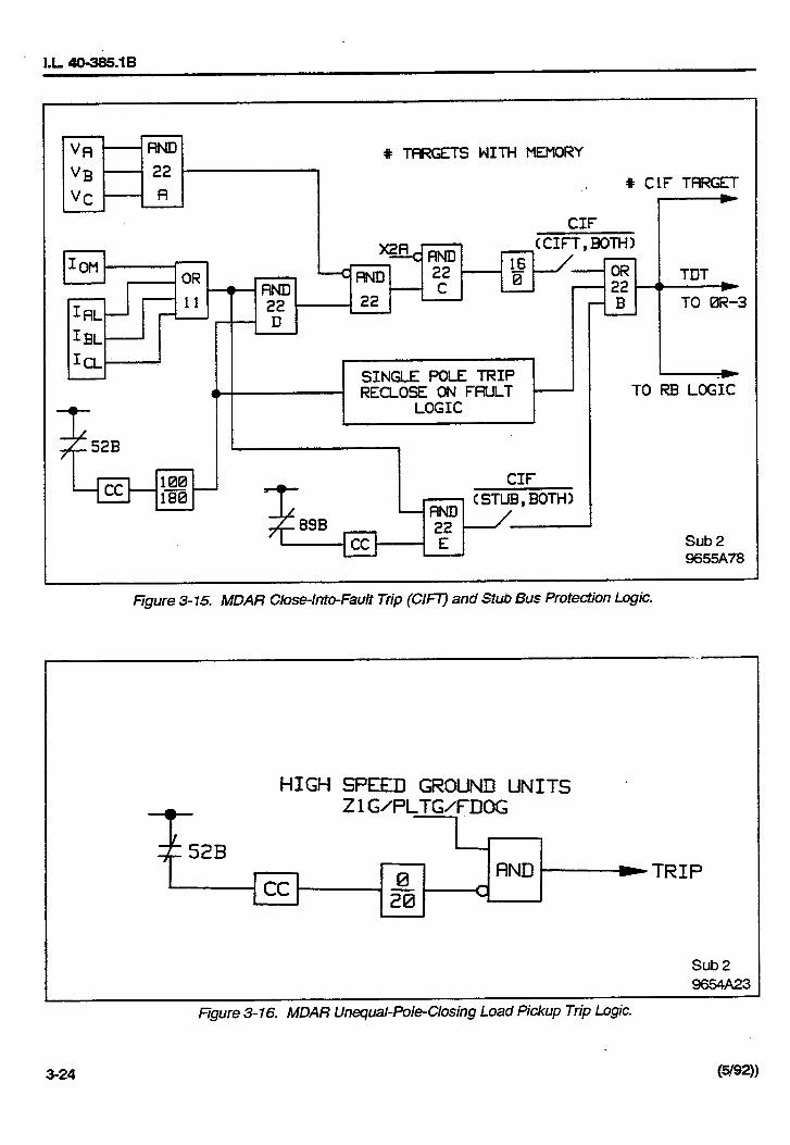


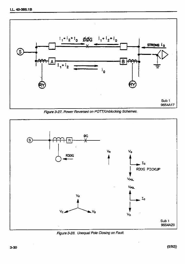


I.L. 40-385.1B
(5/92) 3-33
TABLE 3-1. MDAR CATALOG NUMBERS
Typical Catalog Number *
MDAR DIGITAL MD 3 B 1 S P F R GRELAY SYSTEM (50/60 HZ)
TRIP
Three Pole Trip 3
Single Pole Trip 1
Three Pole Trip w/Programmable Contacts** 8
CURRENT INPUT
1A A
5A B
BATTERY SUPPLY VOLTAGE
48/60 Vdc 4
110/125 Vdc 1
220/250 Vdc 2
POWER SWING BLOCK
Power Swing Block S
No Power Swing Block N
PILOT SYSTEM/CHANNEL INTERFACE
Pilot System-Channel Interface P
Non-Pilot System, No Channel Interface N
TEST SWITCHES
FT-14 Switches F
No FT-14 Switches N
COMMUNICATION DEVICE
RS-232C R
INCOM C
None N
ADDITIONAL FEATURES
Oscillographic Data Storage G
No Oscillographic Data Storage N
Software Version 1.XX Z
* See Drawing 2420F01**Available in later 2.XX Version

I.L. 40-385.1B
3-34 (5/92)
TABLE 3-2. MDAR ACCESSORIES
1. FT-14 TEST PLUG
• Right-Side 1355D32G01
• Left-Side 1355D32G02
2. TEST FIXTURE AND EXTENDER BOARD
• Inner Chassis Test Fixture (5 Amp) 2409F39G01
• Inner Chassis Test Fixture (1 Amp) 2409F39G02
• External Board Assembly 1609C55G01
TABLE 3-3. SINGLE-POLE-TRIP OPERATING MODES
“TTYP”SET ATPOSITION TRIP MODE RECLOSING INITIATE
OFF 3PT on all faults No reclosing
1PR 3PT on all faults RI2 on φG faults only
2PR 3PT on all faults RI2 on φG/φφ/φφG faults
3PR 3PT on all faults RI2 on all faults
SPR SPT on φG faults RI1 on φG faults only3PT on others no reclosing on others
SR3R SPT on φG faults RI1 on φG faults3PT on others RI2 on others

I.L. 40-385.1B
(5/92) 4-1
Section 4. INSTALLATION, OPERATION AND MAINTENANCE
4.1 SEPARATING THE INNER ANDOUTERCHASSIS
It is recommended that the user of this equipmentbecome acquainted with the information in these in-structions before energizing the MDAR and associ-ated assemblies. Failure to observe this precautionmay result in damage to the equipment.
All integrated circuits used on the modules are sen-sitive to and can be damaged by the discharge ofstatic electricity. Electrostatic discharge precautionsshould be observed when operating or testing theMDAR.
CAUTION
Use the following procedure when separatingthe inner chassis from the outer chassis; failureto observe this precaution can cause personalinjury, undesired tripping of outputs and compo-nent damage.
a. Unscrew the front panel screw.
b. If the MDAR does not have FT-14 switches, buthas a power switch on the front panel, turn “OFF”the power switch before sliding out the innerchassis.
c. If the MDAR has FT-14 switches:
1) Remove the FT-14 covers (one on eachside of the MDAR).
2) Open all FT-14 switches.
WARNING: Do Not Touch the outer con-tacts of any FT-14 switch;they may be energized.
3) Slide out the inner chassis.
4) Close all FT-14 switches.
5) Replace the FT-14 covers.
d. Reverse procedures above when replacing theinner chassis into the outer chassis.
4.2 TEST PLUGS AND FT-14 SWITCHES
Test Plugs are available as accessories (see Table3-2); they are inserted into the FT-14 switches for thepurpose of System Function Tests. When the Test
Plugs are inserted, the terminals FT-14/13 (BP) andFT-14/14(BN) must remain closed.
4.3 EXTERNAL WIRING
All external electrical connections pass through theBackplate (Figure 4-1) on the outer chassis. If theMDAR is used without the FT-14 switch, six 14-ter-minal connectors on the Backplate (TB1 throughTB6) are used. If the FT-14 switch (option) is includ-ed, using the two peripheral areas of the MDAR cab-inet, then only four of the 14-terminal connectors(TB2 through TB5) are used. Three DIN connectors(J11, J12, J13) allow for the removal of the outerchassis (Backplane module) from the inner chassis(Interconnect module).
Electrical inputs to the Backplane module, which arerouted either directly through the Backplate orthrough the FT-14 switch to the Backplate, include(Figure 4-1):
• VA, VB, VC and VN
• IA/IAR, IB/IBR, IC/ICR, and IP/IN• BP (48, 125 or 250 Vdc) and BN (negative)
Analog input circuitry consists of four current trans-formers (IA, IB, IC, and IN), three voltage transform-ers, (VA, VB and VC), and low-pass filters. The sev-en transformers are located on the Backplane PCBoard (see Appendix A). The primary winding of allseven transformers are directly-connected to the in-put terminal TB6/1 through 12 (see Functional BlockDiagram, Appendix J); the secondary windings areconnected through the Interconnect module to theFilter module.
As shown in Figures 4-1 and 4-2, dry contact outputsfor breaker failure initiation (BFI), reclosing initiation(RI), reclosing block (RB), failure alarm (AL1), tripalarm (AL2), SEND and STOP are located on theBackplane PC Board. Optical isolators are for PilotEnable, External Reset, Receiver #1 and #2, 52a,52b, SBP (89b) and studs for chassis ground (GND)and location for the Communication Interface arealso shown.
As shown in Figure 4-3, the power system ac quan-tities (Va, Vb, Vc, Vn, Ia, Ib, Ic and In), as well as thedc source are connected to the left side FT-14 switch

I.L. 40-385.1B
4-2 (5/92)
(front view). All the trip contact outputs are connect-ed to the right-side FT-14 switch (front view). Switch-es 13 and 14 on FT-14 may be used for disabling theBreaker Failure Initiation/Reclosing Initiation (BFI/RI) control logic. (See also external connections,Block Diagram, Appendix J.)
The INCOM or RS232 PONI (Product Operated Net-work Interface) communication box is mountedthrough the Backplate of the outer chassis and con-nected to the Backplane module, and remote set-tings (see 4.7).
4.4 MDAR FRONT PANEL DISPLAY
The front panel display consists of a vacuum fluores-cent display, seven LED indicators, seven pushbut-ton switches, and five test points (as shown in Figure1-1).
4.4.1 Vacuum Fluorescent DisplayThe vacuum fluorescent display (blue color) con-tains four alphanumeric characters for both the func-tion field and the value field. All the letters or num-bers are fourteen segment form (7.88mm x 13mm insize).
4.4.2 LED IndicatorsThere are seven LED indicators on the front paneldisplay:
• 1 “relay-in-service” indicator
• 1 “value accepted” indicator
• 5 display-select indicators
When the “Relay-in-Service” LED illuminates, theMDAR Relay is in service, there is dc power to therelay and the relay has passed the self-check andself-test. The LED is turned “OFF” if the Relay-in-service relay has at least one of the internal failuresshown in the “Test” mode, and the trip will beblocked.
The “Value Accepted” LED flashes only once, to in-dicate that a value has been entered successfully.
The five indicators used for the display selection are:
• Settings
• Volts/Amps/Angle
• Last Fault
• Previous Fault
• Test
One of these indicators is always illuminated, indi-cating the mode selected. The display will beblocked momentarily every minute for the purpose ofself-check; this will not affect the relay protectionfunction.
4.4.3 Pushbutton SwitchesThe front panel contains seven pushbutton switches:
• Display Select• Reset Targets• Function Raise• Function Lower• Value Raise• Value Lower• Enter (recessed for security purposes)The “Display Select” pushbutton is used to selectone of the five display modes, which is indicatedwhen the proper LED illuminates. When a fault is de-tected, the “Last Fault” flashes once per second. Iftwo faults are recorded, the “Last Fault” flashestwice per second, and the prior fault will be movedfrom “Last Fault” to “Previous Fault”. The new faultdata will be stored in the “Last Fault” register. By de-pressing the “Reset Targets” pushbutton, the flash-ing LED indicators are cleared, and the LED will re-vert back to the Metering mode. The information inthe “Previous Fault” and “Last Fault” will not be resetfrom the front panel pushbutton switch, but will be re-set from External Reset (TBS/5 and TBS/6) and theremote reset through the Communication Interface.
The “Function Raise” and “Function Lower” pushbut-tons are used to scroll through the information for theselected display mode. The “Value Raise” and “Val-ue Lower” pushbuttons are used to scroll through thedifferent values available for each of the five func-tions. The “Enter” pushbutton is used to enter (inmemory) a new value for settings.
4.4.4 Test PointsFive test points are provided to check the dc powersupply. Refer to these test points on the front paneldisplay:
• -24V• + 5V• -12V• +12V• Common

I.L. 40-385.1B
(5/92) 4-3
Each measurement is taken by inserting one dcprobe (voltmeter) into Common, and the other dcprobe at the voltage being measured.
4.5 FRONT PANEL OPERATION
The front (operator) panel provides a convenientmeans of checking or changing settings, and forchecking relay unit operations after a fault. Informa-tion on fault location, trip types, phase, operatingunits, and breakers which tripped become availableby using the pushbuttons to step through the infor-mation. Targets (fault data) from the last two faultsare retained, even if the relay is deenergized. Theoperator is notified that targets are available by a redflashing LED on the front panel; in addition, alarm 2output-relay contacts are provided for the externalannunciators.
The operator can identify nonfault voltage, currentand phase angle on the front panel display. Settingscan be checked easily, however, any change to thesettings requires the use of the pushbuttons. Whenrelay is in the normal operating mode, it is good prac-tice to set the LED on the Volts/Amps/Angle mode.
4.5.1 Settings ModeIn order to determine the MDAR settings that havebeen entered into the system, continually depressthe “DISPLAY SELECT” pushbutton until the “SET-TINGS” LED is illuminated. Then depress the“FUNCTION RAISE” or “FUNCTION LOWER” push-button, in order to scroll through the MDAR SET-TINGS functions (see Table 4-1). For each settingsfunction displayed, depress the “VALUE RAISE” or“VALUE LOWER” pushbutton in order to scrollthrough the MDAR values available for the particularfunction. (Each value that appears, as each differentfunction appears in the function field, is consideredto be the “current value” used for that particular func-tion.)
In order to change the “current value” of a particularsettings function, “RAISE” or “LOWER” the FUNC-TION field until the desired function appears (e.g.,“RP”). Then “RAISE” or “LOWER” the values in theVALUE field until the desired value appears. If the“ENTER” pushbutton (recessed for security purpos-es) is depressed, the value which appears in theVALUE field will replace the “current value” in mem-ory; but only if the “VALUE ACCEPTED” LED flash-
es once to indicate that the value has been success-fully entered into the system.
For reasons of security, a plastic screw is used tocover the ENTER pushbutton. A wire can be used tolock the plastic screw and to prevent any unautho-rized personnel from changing the settings.
4.5.2 Metering (Volts/Amps/Angle) ModeWhen the Volts/Amps/Angle LED is selected by the“Display Select” pushbutton, the phase A, B, C volt-ages, currents and phase angles are available foron-line display during normal operation. All mea-sured values can be shown by scrolling the “Raise”or “Lower” pushbutton in the FUNCTION field. Thevalues on the display are dependent on the settingsof RP (read primary); RP= YES for the primary sidevalues and RP = NO for the secondary values. Con-ditions such as loss-of-potential, loss-of-current andout-of-step blocking can also be monitored. Thefunction names and values are shown in Table 4-2.
NOTE: All displayed Phase Angles use V A asreference.
4.5.3 Target (Last and Previous Fault) ModeThe MDAR system saves the latest 16 faultsrecords. The “LAST FAULT” information is of themost recent fault, the “PREVIOUS FAULT” informa-tion is of the fault prior to the “LAST FAULT”. Thesedisplays contain the target information along with the“frozen” data at the time of trip. The “LAST FAULT”register shows one or two records stored by flashingthe LED once or twice per second, respectively.These records can be deleted by External Resetvoltage TB/5 (+) and TB5/6 (-) or through a remotecommunication interface. The front panel (RESET)pushbutton allows the user to reset the flashing LEDto Metering position only. It will not erase the fault information.
Different types of faults with related descriptions areshown in Table 4-3. As soon as a fault event is de-tected, the most recent two sets of target data areavailable for display. If the FDAT is set at “TRIP”, the“Last Fault” is the data associated with the most re-cent trip event. The “Previous Fault” contains thedata from the prior trip event. If a single fault occurs,the “Last Fault” LED flashes. If a reclosing is appliedand the system trips, the original “LAST FAULT” in-formation will be transferred to the “Previous Fault”

I.L. 40-385.1B
4-4 (5/92)
memory. The latest trip information will be stored inthe “Last Fault” memory, and its LED flashes twiceper second. If FDAT is set at Z2TR, two events(Zone 2 pickup or trip) will be stored. If FDAT is setat Z2/Z3, the two events will be either Zone 2 pickupor Zone 3 pickup or any type of trip. The same de-scription applies to a remote communication whichcan store up to 16 events.
4.5.4 Test Mode (Self-Check Routine)The software of the MDAR relay contains severalself-check routines (see Section 1.6). When the“Test” mode is selected by the “Display Select” push-button, the failure modes (represented by their cor-responding bits) are shown in the VALUE field, asfollows:
• Bit 0 External RAM Failure• Bit 1 EEPROM Warning• Bit 2 ROM Failure• Bit 3 EEPROM Failure (NON-Volatile memory)• Bit 4 Analog Input Circuit Failure• Bit 5 Microprocessor FailureData types are as follows:
• bit• byte = 8 bits• word = 16 bits• longword = 32 bitsAll bits are expressed in HEX byte form. For exam-ple, if the display shows “Test 1B”, whose binary rep-resentation is 00011011, this means that the relayfailed the self-check in the area of External RAM (bit0), EEPROM (one-out-of-three failure, bit 1), (two-out-of-three failure, bit 3) and Analog Input Circuit(bit 4). Normally, the test mode should show “Test0", meaning that the relay has passed the self-checkroutines.
When the selector is in TEST mode, scroll the func-tion field by the Raise pushbutton. The Value fielddisplay shows RS1 (Carrier Receiver #1), RS2 (Car-rier Receiver #2), RS1, 2 (Carrier Receiver #1 and#2), and TK (Carrier Send) for the use of MDARfunctional test. Refer to the Pilot Acceptance Test(Appendix H, Section 1.1.13) for more detailed infor-mation. If jumper (JP5) on the microprocessor mod-ule is IN, the following ten functions will be shown:
• TRIP • AL1• BFI • AL2
• RI1 • GS
• RI2 • SEND
• RB • STOP
All of these contact outputs can be tested by press-ing the “ENTER” pushbutton. (see Appendix I, Sec-tion 1.13).
4.6 JUMPER CONTROLS
The following jumpers are set at the factory; the cus-tomer normally does not need to move the jumpers.Refer to Table 4-4 for the recommended jumper po-sitions.
4.6.1 Backplane ModuleAn external jumper should be wired to terminals 13/14 of switch FT-14.
When switch FT-14/13 or FT-14/14 is opened, theBFI and RI output relays are deenergized to preventBFI and RI contact closures during system functiontest.
4.6.2 Interconnect ModuleThe factory sets jumpers (JMP1 through JMP6 andJMP13) for 48 Vdc or 125 Vdc input source.
JMP7 & 9 are used for Stub Bus Protection (SBP). IfSBP is not used, move JMP7 & 9 to 8 & 10 positionfor the second set of AL2-2 use.
CAUTION
If the customer intends to use a voltage otherthan 48 Vdc or 125 Vdc, see Interconnect ModuleSchematic, Appendix B.
4.6.3 Microprocessor ModuleThe following jumpers are normally set during facto-ry calibration:
• JMP1, JMP8, JMP9 for EEPROM and RAMcircuitries, and are nor-mally set to position 1-2.
• JMP2 normally set to position 2-3 for standard application.Set to position 1-2 for pro-grammable output contactselection (future applica-tion).
• JMP3, JMP10, JMP11JMP12 Not used
• JMP4 set to “IN” for trip contactwith dropout time delay.

I.L. 40-385.1B
(5/92) 4-5
• JMP5 set to “IN” for output con-tact tests.
• JMP6 normally set to “OUT” po-sition; set to “IN” whenmaking A/D converter cal-ibration.
NOTE: Should the customer need to gain ac-cess to any of the jumpers (above), seeSection 4.10, and Appendix E.
4.7 COMMUNICATION INTERFACE
Two options are available for interfacing betweenMDAR and a variety of local and remote communi-cation devices.
• RS-232C - for single point computer communica-tion
• INCOM®/PONI1 - for local network communica-tion
An IBM® AT®or XT compatible computer, with soft-ware provided (WRELCOM), can be used to monitorthe settings, 16 fault data, 16 intermediate data, andmetering information. For a remote setting, SETRshould be set to “YES”; then the settings can bechanged (remotely) with a user-defined password. Ifa user loses his assigned password, a new pass-word can be installed by turning the MDAR relay’s dcpower supply “OFF” and then “ON”. MDAR allows achange of password within the next 15 minutes, byusing a default “PASSWORD”.
When in the remote mode, the computer can disablethe local setting by showing SET = REM (in the Me-tering mode). Then, the setting cannot be changedlocally. In this situation, the only way to change a set-ting locally would be to turn the dc power “OFF” andthen “ON”. The computer will allow for a local settingchange within 15 minutes.
4.8 SIXTEEN FAULT TARGET DATA
The MDAR saves the latest 16 fault records, but onlythe latest two fault records can be accessed from thefront panel. For complete 16 fault data, one of the
1. INCOM”®
is a registered trademark ofthe Westinghouse Electric Corporation,Inc., which stands for INtegratedCOMmunications. The “PONI” acronymstands for Product Operated NetworkInterface.
communication interface devices are necessary.The activation of fault data storage is controlled bysetting FDAT. (Refer to Section 3.4.19 for detailedinformation.) The 16 intermediate fault targets are astandard feature. The activation of data storage isbased on the setting of the optional OSC (see nextsection). If OSC is not included, intermediate data isprovided one sample per cycle.
4.9 OSCILLOGRAPHIC DATA (Optional Feature)
Sixteen sets of oscillographic data are stored inMDAR. Each set includes seven analog traces (Va,Vb, Vc, Ia, Ib, Ic and In), with one cycle pre-fault and7-cycle fault information, and 20 sets of digital databased on 8 samples per cycle.
The oscillographic data (OSC) collection can be setfor TRIP, Z2TR, Z2/Z3, and dVdI. For setting of OSC= TRIP, data are collected for the trip events. Thedata collection is started from dVdI if the trip occurswithin 7 cycles. For OSC = Z2TR, the data collectionis triggered by Zone 2 pickup or any types of trip. ForOSC = Z2/Z3, the collection is triggered by eitherZone 2 or Zone 3 pickup (including the Zone 3 re-verse setting) or trip. For OSC = dVdI, the data col-lection is caused by any line disturbance, e.g., a sud-den phase current change (by 1 amp) or a groundcurrent change (by 0.5 Amp), or a voltage change(∆V) greater than 7Vdc.
NOTE: Setting at dVdI is not recommended be-cause a lot of meaningless data will bestored, such as breaker opening or clos-ing, etc.
4.10 ROUTINE VISUAL INSPECTION
With the exception of Routine Visual Inspection, theMDAR relay assembly should be maintenance-freefor one year. A program of Routine Visual Inspectionshould include:
• Condition of cabinet or other housing
• Tightness of mounting hardware and fuses
• Proper seating of plug-in relays and sub-assemblies
• Condition of external wiring
• Appearance of printed circuit boards and compo-nents
• Signs of overheating in equipment

I.L. 40-385.1B
4-6 (5/92)
4.11 ACCEPTANCE TESTING
The customer should perform the MDAR Accep-tance Tests (see Appendix I) on receipt of shipment.
4.12 NORMAL PRECAUTIONS
Troubleshooting is not recommended due to the so-phistication of the Microprocessor unit.
CAUTION
With the exception of checking to insure propermating of connectors, or setting jumpers, the fol-lowing procedures are normally not recommend-ed. (If there is a problem with the MDAR, itshould be returned to the factory. See PREF-ACE.)
4.13 DISASSEMBLY PROCEDURES
a. Remove the inner chassis from the outer chassis,by unscrewing the center lockscrew (on the frontpanel), and unsnapping the two covers from the(optional) FT-14 switches, if the FT-14 switchesare a part of the MDAR system.
NOTE: The inner-chassis (sub-assembly)slides in and out of the outer chassisfrom the front. Mating connectors in-side the case eliminate the need to
disconnect external wiring when theinner chassis is removed.
b. Remove the (optional) FT-14 switches, mountedby two screws on the side walls.
c. Remove the front panel (with the Display module)from the inner chassis, by unscrewing four screwsbehind the front panel.
d. Remove the Microprocessor module, by loosen-ing six mounting screws, and unplugging themodule from the Interconnect module.
e. Remove the Option (module), if the option mod-ule is part of the MDAR system, by unscrewing 2mounting screws from the center support bar, andunplugging the Option module from the Intercon-nect module.
f. Remove the Power Supply and Filter modules, byfirst removing the Microprocessor module and thesupport cross bar.
g. Remove the Backplate, by unscrewing themounting hardware from the rear of theBackplate.
h. Gain access to the Backplane and Transformermodules, by removing the Backplate.


I.L. 40-385.1B
4-10 (5/92)
Displayed atFunction Field Value Field
Information/Settings (using 5 A ct and 60 Hz)(SEE NOTE ON SHEET 3)
Software version VERS numerical (0,1)Oscillographic data initiation OSC * TRIP/Z2TR/Z2Z3/∆V∆IFault data initiation FDAT TRIP/Z2TR/Z2Z3ct ratio CTR 30-5000 (5)PT ratio VTR 300-7000 (10)Rated freq. FREQ 60, 50ct secondary rating CTYP 5 or 1Enable/disable readoutsin primary I & V values RP YES/NOReactance for fault location
(ohms per unit distance) XPUD 0.300-1.500, in 0.001/DTYPFault location, displayed in km or miles DTYP KM or MI (miles)Reclosing mode TTYP1. 3PT on all faults, no RI OFF2. 3PT on all faults, with 3RI on φGF 1PR3. 3PT on all faults, with 3RI on φGF/2φF 2PR4. 3PT on all faults, w/3RI 3PR5. SPT on φGF with SRI
3PT on MφF without RI SPR6. SPT on φGF with SRI
3PT on MφF with 3RI SR3RSingle phasing limit timer 62T * 0.300-5000, in 0.050 sec. stepsRI on Z1T Z1RI YES/NORI on Z2T Z2RI YES/NORI ON Z3T Z3RI YES/NOBreaker Failure Reclose block BFRB * YES/NOPilot logic control PLT * YES/NOPilot system selection: STYP1. Non-Pilot, 3-zone distance 3ZNP2. Zone-1 extension Z1E3. Permissive overreach transfer trip
or unblocking POTT4. Permissive underreach transfer trip PUTT5. Blocking BLKForward Direction Ground Timer FDGT * BLK, 0 to 15 cycles in 1cycle stepsWeakfeed Enable WFEN * YES/NO3-Terminal Line Application 3TRM * YES/NOBlocking system channelcoordination timer BLKT * 0-98, in 2 ms stepsReverse block sw. RBSW * OmittedPilot phase setting PLTP * OUT, 0.01-50.00 in 0.01 Ω stepsPilot ground setting PLTG * OUT, 0.01-50.00 in 0.01 Ω steps
*Optional
TABLE 4-1. SETTING DISPLAY (SHEET 1 OF 3)

I.L. 40-385.1B
(5/92) 4-11
TABLE 4-1. SETTING DISPLAY (SHEET 2 OF 3)
Displayed atFunction Field Value Field
Information/Settings (using 5 A ct and 60 Hz)(SEE NOTE ON SHEET 3)
Zone 1 phase unit Z1P OUT, 0.01-50.00 in 0.01 Ω stepsZone 1 ground unit Z1G OUT, 0.01-50.00 in 0.01 Ω stepsZone 1 delay trip timer T1 YES/NO, 2 cycles if YESZone 2 phase unit Z2P OUT, 0.01-50.00 in 0.01 Ω stepsZone 2 phase timer T2P BLK, 0.10-2.99, in 0.01 sec. stepsZone 2 ground unit Z2G OUT, 0.01-50.00 in 0.01 Ω stepsZone 2 ground timer T2G BLK, 0.10-2.99, in 0.01 sec. stepsZone 3 phase unit Z3P OUT, 0.10-50.00 in 0.01 Ω stepsZone 3 phase timer T3P BLK, 0.10-9.99 in 0.01 sec. stepsZone 3 ground unit Z3G BLK, 0.01-50, 0.01 Ω stepsZone 3 ground timer T3G BLK, 0.10-9.99 in 0.01 sec. stepsZone 3 direction Z3FR FWD/REVPos. Seq. line impedance angle PANG 40-90, in 1.0 degree stepsZero Seq. line impedance angle GANG 40-90, in 1.0 degree stepsZOL/Z1L ZR 0.1-7.0, in 0.1 stepsLow Voltage unit LV 40-60 in 1.0V (rms) stepsOvercurrent units
Low set phase IL 0.5-10, in 0.1 A stepsLow set ground IOS 0.5-10, in 0.1 A stepsMed. set ground IOM 0.5-10, in 0.1 A stepsHigh set phase ITP OUT, 2-150.0, 0.5 A stepsHigh set ground ITG OUT, 2-150.0, 0.5 A steps
Out-of-step block OSB* YES/NOOSB override timer OSOT* 400-4000 in 16 ms stepsOSB inner blinder RT 1.00-15.00, in 0.10 Ω stepsOSB outer blinder RU* 3.00-15.00, in 0.10 Ω stepsDirectional overcurrent, zeroor negative sequence DIRU ZSEQ/NSEQ/DUALDirectional overcurrentground backup time curve family GBCV OUT, CO2,5,6,7,8,9,11Ground backup pick-up GBPU 0.5-4.0, in 0.1 A stepsGround backup time curves within family GTC 1-63, in 1.0 stepsChoice of directional or non-directional ground backup GDIR YES/NO
* Optional

I.L. 40-385.1B
4-12 (5/92)
TABLE 4-1. SETTING DISPLAY (SHEET 3 OF 3)
Displayed atFunction Field Value Field
Information/Settings (using 5 A ct and 60 Hz)(SEE NOTE)
CIF trip/stub bus protection CIF CIFT/STUB/BOTH/NOLLT trip LLT YES/FDOG/NOLOP block LOPB YES/NOLOI Block LOIB YES/NOAlarm 2 (Trip) Seal-In AL2S YES/NORemote Setting SETR YES/NOReal Time Clock TIME YES/NO1. Set Year YEAR 1980-2079, in 1 year steps2. Set Month MNTH 1-12, in 1 month steps3. Set Day DAY 1-31 in 1 day steps4. Set Weekday WDAY Sun, Mon, Tues,
Wed, Thur, Fri, Sat5. Set Hour HOUR 0-24, in 1 hour steps6. Set Minute MIN 0-60, in 1 minute steps
NOTE: WHEN THE CTYP FUNCTION IS SET AT 1 AMPERE, THE RANGE OF THE FOLLOWING FUNC-TIONS ARE AS SHOWN BELOW:
• ZIP/ZIG/Z2P/Z2G Z3P/Z3G/PLTP/PLTG 0.05-250.00, in 0.05 Ω steps
• ITP/ITG 0.4-30.0, in 0.1 A steps
• IL/IOS/IOM 0.1-2.0, in 0.02 A steps
NOTE: SEE ALSO SECTION 5.2.4, SELECTIONS OF CTYP SETTINGS.
NOTE: SEE PREFACE FOR INFORMATION ON SETTING NOMENCLATURE APPLIQUES.
NOTE: The increments of timers are based on the line frequency, e.g., 16 msec for 60 Hz and 20 msecfor 50 Hz (to the nearest msec)

I.L. 40-385.1B
(5/92) 4-13
TABLE 4-2. METERING DISPLAY
Displayed atInformation Function Field Value Field
Phase A current (mag.) IA numerical, A (X.X)Phase A current (ang.) IA deg. (X.X)Phase A voltage (mag.) VAG numerical, v (XX.X)Phase A voltage (ang.) VAG deg. (XX)
Phase B current (mag.) IB (0.0)Phase B current (ang.) IB (0)Phase B voltage (mag.) VBG (0.0)Phase B voltage (deg.) VBG (0)
Phase C current (mag.) IC (0.0)Phase C current (ang.) IC (0)Phase C voltage (mag.) VCG (0.0)Phase C voltage (ang.) VCG (0)Month / Day DATE numerical (00.00)Hour / Minute TIME numerical (00.00)
Local/Remote Setting SET LOC/REM/BOTHCarrier Receive -1 RX1* YES/NOCarrier Receive -2 RX2* YES/NOLOP indication LOP YES/NOLOI indication LOI YES/NOOut-of-Step Block OSB* YES/NO
* Optional

I.L. 40-385.1B
4-14 (5/92)
TABLE 4-3. TARGET (FAULT DATA) DISPLAY (SHEET 1 OF 2)
Displayed atFunction Value
Information Field Field
Month / Day DATE XX.XXYear YEAR XXXXHour / Minute TIME XX.XXSecond SEC XX.XX
Fault type FTYP AG/BG/CG/AB/BC/CA/ABG/BCG/CAG/ABC
BKR.#1 φA tripped BK1A YES/NOBKR.#1 φB tripped BK1B YES/NOBKR.#1 φC tripped BK1C YES/NOBKR.#2 φA tripped BK2A YES/NOBKR.#2 φB tripped BK2B YES/NOBKR.#2 φC tripped BK2C YES/NOZone 1 phase tripped Z1P YES/NOZone 1 ground tripped Z1G YES/NOZone 2 phase tripped Z2P YES/NOZone 2 ground tripped Z2G YES/NOZone 3 phase tripped Z3P YES/NOZone 3 ground tripped Z3G YES/NOPilot phase tripped PLTP* YES/NOPilot ground tripped PLTG* YES/NOHigh set phase tripped ITP YES/NOHigh set ground tripped ITG YES/NOClose-into fault trip CIF YES/NOLoad-loss tripped LLT YES/NOGround backup tripped GB YES/NOSPF tripped (SPF) SPT* YES/NO62T tripped (SPT) 62T* YES/NOFault location Z (In ohms)Fault Z angle FANG (numerical)Fault distance DMI or DKM (in miles or KM)Prefault load current PFLC numerical, APrefault phase voltage PFLV numerical VPrefault load angle LP numerical deg.
Carrier send SEND* YES/NOReceiver #1 RX1* YES/NOReceiver #2 RX2* YES/NOWeakfeed tripped WFT* YES/NO

I.L. 40-385.1B
(5/92) 4-15
TABLE 4-3. TARGET (FAULT DATA) DISPLAY (SHEET 2 OF 2)
Displayed at
Function ValueInformation Field Field
Fault type FTYP AG/BG/CB/AB/BC/CAABG/BCG/CAG/ABC
Fault voltage VA (mag.) VPA numerical, V(ang.) VPA numerical deg.
Fault voltage VB(mag.) VPB numerical V(ang.) VPB numerical deg.
Fault voltage VC(mag.) VPC numerical V(ang.) VPC numerical deg.
Fault voltage 3V0(mag.) 3VO numerical V(ang.) 3VO numerical deg.
Fault voltage IA(mag.) IPA numerical A(deg.) IPA numerical deg.
Fault voltage IB(mag.) IPB numerical A(deg.) IPB numerical deg.
Fault voltage IC(mag.) IPC numerical A(deg.) IPC numerical deg.
Fault current IN(mag.) IN numerical A(deg.) IN numerical deg.
Month/Day DATE XX.XXYear YEAR 1980-2079Hour/Minute TIME XX.XXSecond SEC XX.XX

I.L. 40-385.1B
4-16 (5/92)
INTERCONNECT Module
JMP 1 to 6, & 13 For the rated input dc voltageJMP 7 & 9 For Stub Bus ProtectionJMP 8 & 10 For the trip alarm (AL2-2)JMP 11 & 12 For MDAR with FT switches only
MICROPROCESSOR Module
JUMPER POSITION FUNCTION
JMP 1 1-2 EEPROM (8kx8)JMP 2 2-3 StandardJMP 3 IN Spare jumperJMP 4 OUT No dropout time delay for trip contactsJMP 5 OUT Disable output contact testJMP 6 OUT Normal operationJMP 8 & 9 1-2 RAM (32kx8)JMP 10 IN Spare jumperJMP 11 & 12 OUT Spare positions
TABLE 4-4. RECOMMENDED JUMPER POSITIONS (V2.XX)

I.L. 40-385.1B
(5/92) 5-1
Section 5. SETTING CALCULATIONS
5.1.3 Zone 2 Distance Unit Settings
Generally, Zone-2 reach is set for 100% of the pro-tected line plus 50% of the shortest adjacent line. Ifthe shortest (or only) adjacent line primary imped-ance is 20 ohms, then the Zone-2 reach settingwould be:
Z2P = 6 + (20 x 0.5) x 240/600 = 10 and
Z2G = 10
NOTE: Z2P and Z2G can be set for differentvalues if the application is required.
5.1.4 Zone 3 Distance Unit Settings
Generally, Zone-3 reach is set for 100% of the pro-tected line plus 100% of the longest adjacent lineemanating from the remote bus, while accounting forthe infeed from the same remote bus.
If the longest (or only) adjacent line from the remotebus is 25 ohms primary, and the infeed effect may in-crease its impedance by 30%, then the Zone-3reach setting should be:
Z3P = 6 + (25 x 1.3) x 240/600 = 19 and
Z3G = 19
NOTE: Z3P and Z3G can be set for different val-ues if the application is required.
5.1.5 Overcurrent Unit Setting
a. The low set phase overcurrent unit is used for su-pervising the OSB, the load-loss-trip and CIF func-tions. It should be set higher than the line chargingcurrent and below the minimum load current.
NOTE: It should be set above the maximumtapped load current if applicable.
Assume that the line charging current is negligiblefor this line section, and the minimum load current is2.0 A secondary, then the low set phase overcurrentunit setting should be:
IL = 1
b. The low-set ground overcurrent unit is used forsupervising the reverse directional overcurrentground unit (RDOG). It should be set as sensitive aspossible. A setting of 0.5 amperes is recommended:
IOS = 0.5
Z1L = Z2L = 15∠77° x 240/600 = 6∠77° ohms
Z0L = 50∠73° x 240/600 = 20∠73° ohms
5.1.1 Ratio of Zero and Positive SequenceImpedances
ZR = Z0L/Z1L = 20/6 = 3.33
then MDAR will automatically calculate the zero se-quence current compensation factor (k0) by using
the value of ZR, i.e.,
5.1.2 Zone 1 Distance Unit Settings
A setting of 80% of the line impedance for zone-1reach is recommended, thus the Zone-1 phase andground reach should be:
Z1P = 6 x 0.8 = 4.8 and
Z1G = 6 x 0.8 = 4.8
NOTE: Z1P and Z1G can be set for different val-ues if the application is required. Referto Section H, Step 10 for calculation andexample.
k0 ZoL Z1L–( )/3Z1L ZR GANG PANG–( ) -1∠[ ]/3= =
5.1 CALCULATION OF MDAR SETTINGS
The following MDAR setting calculations correspondto the setting categories in the Installation Section(4). Assume that the protected line has the followingdata:
• 18.27 miles
• Line reactance 0.8 ohms/mile
• 69 kV, 60 cycles
• Positive and negative sequence impedances:
ZIL(Pri) = Z2L(Pri) = 15∠77° ohms
• Zero sequence impedance: /Z0L(pri) = 50∠73° ohms
• Current Transformer Ratio (CTR):RC = 1200/5 = 240 (Set CTR = 240)
• Voltage Transformer Ratio (VTR):RV = 600/1 = 600 (Set VTR = 600)
• Relay secondary ohmic impedances are:
Z = Zpri x RC/RV

I.L. 40-385.1B
5-2 (5/92)
c. The medium set ground overcurrent unit is usedfor supervising the Zone 1, Zone 2 and Zone 3ground distance units (Z1G, Z2G and Z3G), theforward directional overcurrent ground unit (FDOG).Generally, it is recommended to be set 2 times theIOS setting.
IOM = 2 x IOS = 1.0
d. The directional high set overcurrent phase andground units (ITP and ITG) are used for direct tripfunction. The general setting criterion for the instan-taneous direct trip unit is:
The unit should be set higher than 1.15 times themaximum fault on the remote bus, where the factorof 1.15 is to allow for the transient overreach. For thisexample, assume that the maximum load is not high-er than the maximum forward end zone fault current,and the maximum phase and ground fault currentson the remote bus are 20 and 24 amperes, respec-tively, then the settings of the high-set phase (ITP)and the high-set ground (ITG) should be:
ITP = 20 x 1.15 = 23
ITG = 24 x 1.15 = 27.6
5.1.6 OSB Blinder Settings (RT and RU)
The requirements for setting the blinder units are:
• Inner blinder must be set to accommodate maxi-mum fault resistance for internal 3-phase fault
• Inner blinder should not operate on severe stableswings
• Outer blinder must have adequate separationfrom inner blinder for fastest out-of-step swing tobe acknowledged as an out-of-step condition
• Outer blinder must not operate on load
a. Setting the Inner Blinder
If the OSB is used to supervise tripping of the 3φ uniton heavy load current, the inner blinder 21BI must beset sufficiently far apart to accommodate the maxi-mum fault arc resistance. A reasonable approxima-tion of arc resistance at fault inception is 400 voltsper foot. If a maximum ratio of “line voltage per spac-ing” is 10,000 volts/ft. for a high voltage transmissionline, and if a minimum internal 3-phase fault currentis calculated as:
Imin. = [E / 1.73(ZA+ZL)]
where ZA is maximum equivalent source impedance,ZL is line impedance and E is line-to-line voltage.
then Rmax.= 400 x FT / Imin.
= 400x1.73(ZA+ZL)/10000
= 0.0693 (ZA+ZL)
Adding a 50% margin to cover the inaccuracies ofthis expression:
Rmax.= 0.104(ZA+ZL) primary ohms
RS= 0.104(ZA+ZL)RC/RV secondary ohms
Set inner blinder to:
RT = RS x COS (90° - PANG) (1)
This is the minimum permissible inner blinder settingwhen it is used to provide a restricted trip area for adistance relay.
Another criterion that may be considered is basedupon the rule of thumb that stable swings will not in-volve an angular separation between generator volt-ages in excess of 120°. This would give an approxi-mate maximum of:
Zinner = (ZA+ZL+ZB)/ (2x1.73) (2)
= 0.288(ZA+ZL+ZB) primary ohms
Zinner = 0.288(ZA+ZL+ZB)RC/RV secondary ohm
where ZB is the equivalent maximum source imped-ance at the end of the line away from ZA.
An inner blinder setting between the extremes ofequations (1) and (2) may be used. This provides op-eration for any 3-phase fault with arc resistance, andrestraint for any stable swing. Except in those caseswhere very fast out-of-step swings are expected, thelarger setting can be used.
It will usually be possible to use the minimum innerblinder setting of 1.5 ohms.
b. Setting the Outer Blinder
For slow out-of-step swings, a reasonably closeplacement of outer to inner blinder characteristic ispossible. The separation must, however, be basedon the fastest out-of-step swing expected. A 50 msinterval is inherent in the out-of-step sensing logic,and the outer blinder must operate 50 ms or moreahead of the inner blinder.
Since the rate of change of the ohmic value mani-fested to the blinder elements is dependent upon ac-

I.L. 40-385.1B
(5/92) 5-3
celerating power and system WR2, it is impossible togeneralize. However, based on an inertia constant(H) equal to 3, and the severe assumption of full loadrejection, a machine will experience (assuming auniform acceleration) an angular change in positionof no more than 20° per cycle on the first half slip cy-cle.
If the inner blinder were set for (0.104ZT), and the
very severe 20° per cycle swing rate were used, theouter blinder should be set for approximately:
Zouter = 0.5 ZT primary ohms (3)
where ZT = ZA + ZB + ZL
This is the minimum setting of the outer blinder for a20° per cycle swing rate.
5.1.7 Overcurrent Ground Backup Unit (GB)
The overcurrent ground backup unit GB providesseven sets of curves, which are similar to the COand MCO curves, for backing up the distance groundon high resistance ground faults. Four settings (GB-CV, GBPU, GTC and GDIR) should be determinedfor applying this unit.
a. GBCV is the ground backup curve selection.Seven sets of familiar CO curves are provided(C02,5,6,7,8,9 and 11), and are shown in Figures 2-1 thru 2-7. The selection is based on the applicationand coordination time. A selection of “OUT” disablesthe ground backup function.
b. GBPU is the current level setting. Its range is 0.5to 4.0 amperes in 0.5 steps. In general, the currentlevel setting criterion is:
(IFmin /2) > Setting level > 2 x (Max.residual load, 3I0)
where IFmin = Minimum ground fault current for a fault two buses away
For better sensitivity, GBPU should be set at 0.5 am-peres, this would be adequate for most of the appli-cation.
c. GTC is the time delay setting of the GB unit. Asshown in Figures 2-1 thru 2-7, it has 63 setting selec-tions, from 1 to 63 in 1.0 steps. In general, the timedelay setting should be coordinated with any protec-tive device downstream of the line section.
d.GDIR is the setting for directional control selection.The GB unit will become a directional torque controlovercurrent ground unit if GDIR is set at YES. Thefollowing equation can be used to calculate the triptime for all CO curves from CO-2 thru CO-11 :
T (sec) = (for 3I0 ≥ 1.5)
T (sec) = (for 1<3I0< 1.5)
Where 3I0 =
GBPU = Pickup current setting (0.5 to 4.0A).
GTC = Time curve dial setting (1 to 63).
T0, K, C, P and R are constants, and are shown in
Table 5-3. (Refer also to the example in Appendix H,Section 1.1.9.)
Taking the CO-8 curve set as an example (see Fig-ure 2-5), assuming that the maximum 3Io of unbal-anced load is 0.2A, the minimum ground fault cur-rent for a fault two buses away is 10A, and 0.7seconds is required for coordination with current of20 times the GBPU setting, then the settings of theGB function should be as shown below:
10/2 > GB > 2 x 0.2 set GBPU = 0.5
Using the curve in Figure 2-1, for 0.7 seconds at 20times the GBPU setting, GTC should be set to 24.
• Set GBCV = C0-8 and• Set GDIR = YES if directional control is required.
5.1.8 Timer Settings
a. Zone-2 timer (T2) setting should be coordinatedwith the Zone-1 and other high-speed trip units onthe adjacent line terminal. Coordination Time Inter-val (CTI) of 0.3 to 0.5 seconds is recommended. Forexample, if T2 of 0.4 seconds is used, then thephase and ground Zone-2 timers should be set asfollows:
T2P = 0.4 and T2G = 0.4
NOTE: T2P and T2G are separate timers; theycan be set at different time settings.
b. Zone-3 timer (T3) settings would be similar to theabove. For example, if T3 of 0.8 seconds is required,then the phase and ground Zone-3 timer should beset as follows:
T0K
3I0 C–( )P--------------------------+
GTC24 000,------------------×
R3I0 1–( )---------------------
GTC24 000,------------------×
IFGBPU------------------

I.L. 40-385.1B
5-4 (5/92)
T3P = 0.8 and T3G = 0.8
NOTE: T3P and T3G are separate timers; theycan be set at a different time settings.
c. For out-of-step block (OSB), if applied, the OSBoverride timer setting (OSOT) is determined by thepower system operation. Its range is 400 to 4000 ms,in 16 ms steps. For example, set MDAR OSOT =500 if OSB override time of 500 ms is required.
d. For single-pole trip application only, the singlephasing limit timer setting (62T) is for preventingthermal damage to rotating machines, due to the I2component during single phasing. Its range is 300 to5000 ms. in 50 ms steps. The setting should be
based on the poorest (I2)2t constant of the machines
in service. For example, set MDAR 62T = 1550, if3PT is required before 1.55 seconds and after onepole has been open and the breaker does not or can-not reclose.
e. For the blocking system only, the channel coordi-nation timer setting (BLKT) is based on the followingapplication criteria:
BLKT > (Slowest remote carrier start time + channeltime + margin) - (the fastest local 21P/21NP pickuptime)
Where channel time includes the transmitter and re-ceiver times, and the times which occur betweenthese devices, e.g., wave propagation, interfacingrelays, etc.
For MDAR:fastest 21P/21NP pickup time = 14 msslowest carrier start time = 4 mssuggested margin time = 2 ms
For example, the MDAR channel coordination timershould be determined as shown below, if the chan-nel time is 3 ms.
BLKT = (4 + 3 + 2) - 14= -5
i.e., set BLKT = 0
5.2 SELECTION OF MDAR SETTINGS
The following settings are determined by the appli-cation. They do not require calculation.
5.2.1 The OSC setting is for selecting one of the 4ways (TRIP/Z2TR/Z2Z3/∆I∆V) to initiate the oscillo-graphic data taken, where:
TRIP --- start data taken only if trip action occurs.
Z2TR --- start data taken if Zone 2 units pick up, orany trip action occurs.
Z2Z3 --- start data taken if Zone 2 or Zone 3 unitspick up, or any trip action occurs.
∆I∆V --- start data taken if ∆I, ∆V, Zone 2 or Zone 3units pick up, or any trip action occurs.
NOTE: The setting of ∆I, ∆V, for OSC is not rec-ommended.
5.2.2 The FDAT setting is for selecting one of the3 ways (TRIP/Z2TR/Z2Z3) to initiate the fault datataken, where:
TRIP --- start to store fault data only if trip actionoccurs.
Z2TR --- start to store fault data if Zone 2 units pickup or any trip action occurs.
Z2Z3 --- start to store fault data if Zone 2 or Zone 3units pick up or any trip action occurs.
5.2.3 The current transformer ratio setting(CTR) is used for the load current monitoring, if it isselected to be displayed in primary amperes. It hasno effect on the protective relaying system. For thisexample, set CTR = 240.
5.2.4 The voltage transformer ratio setting(VTR) is used for the system voltage monitoring, if itis selected to be displayed in primary volts. It has noeffect on the protective relaying system. For this ex-ample, set VTR = 600.
5.2.5 The frequency setting (FREQ) should beselected to match the power system operating fre-quency. For example, select FREQ = 60 if the powersystem operating frequency is 60 Hertz.
5.2.6 The current transformer type setting (CT-YP) provides the flexibility for 5 Amp or 1 Amp ratedcurrent transformer selection. For example, selectand set CTYP = 5 if a 5 Amp current transformer isused.
The setting of CTYP affects all the distance unit andovercurrent unit setting ranges. The ranges will beautomatically changed as listed in Table 5-1.
5.2.7 The read primary setting (RP) should beset at YES if all the monitoring ac voltages and cur-rents are selected to be displayed in primary KV andKA values, respectively.
5.2.8 The ohms per unit distance of the line re-actance setting (XPUD) is the multiplier for faultdistance display. It has a range of 0.3 to 1.5 in 0.001

I.L. 40-385.1B
(5/92) 5-5
steps. In this example, the line reactance is 0.8ohms/mile; set XPUD = 0.8.
The fault distance calculation is as follows:
Where ZS is the secondary impedance magnitude,
and FANG is the fault angle.
5.2.9 The setting of DTYP (distance type) has aselection of MILE and KM. It should be selected tomatch with the setting of XPUD. For this example,select DTYP = MILE.
5.2.10 The setting of TTYP is for selecting the re-closing mode in single pole trip applications (ifapplicable). It has six selecting positions (OFF, 1PR,2PR, 3PR, SPR, and SR3R). Refer to the guidelinesfor reclosing mode programming for the TTYP set-ting selection.
5.2.11 For an SPT application , set the 62T singlephasing limit timer from 300 to 5000 ms in 50 ms
steps. The setting is based on the generator’s (I2) 2tperformance. LV should be set between 85% and90% of the rated line-to-neutral voltage.
5.2.12 The settings of Z1RI, Z2RI and Z3R I pro-vide the selectivity for Zone 1 RI (reclosing initiation),Zone 2 RI and Zone 3 RI, respectively. For the non-pilot system application, set Z1RI, Z2RI and/or Z3RIto YES, if RI is required when the particular distancezone operates. For the pilot reclosing, Z1RI shouldbe set to “YES”.
5.2.13 For a pilot system , set BFRB to YES if RBon the breaker failure squelch feature is required.
5.2.14 The setting of PLT (pilot) combines with thesignal of Pilot Enable (on the backplane panel) andcontrols the operation of pilot and reclosing initiation.The absence of either signal will:
• disable the pilot system
• block the RI2 output, and
• allow an RI1 output for a non-pilot system.
The PLT can be set either locally from the front panelor, remotely, via the communication channel.
5.2.15 The STYP (system type) selects the desiredrelaying system for the application. It has two selec-tions: 3ZNP (3 zone non-pilot) and Z1E (Zone 1extension) in the non-pilot MDAR. There are five se-lections: 3ZNP, Z1E, POTT (permissive overreach
DMIVTRCTR-------------
ZS FANG∠sin×XPUD
---------------------------------------------×=
transfer trip or unblocking), PUTT (permissiveunderreach transfer trip) and BLK (blocking) in thepilot MDAR. It should be set to the desired selection.
5.2.16 For the pilot MDAR only , the WFEN (weak-feed enable) selection should be set to YES for theweakfeed terminal, if applicable.
5.2.17 For pilot MDAR only, the 3TRM (3 termi-nals) setting should be selected to YES for all of thethree terminals that apply.
5.2.18 For application of POTT/BLK systems, thetransient block logic is always in the POTT/BLK sys-tem, but it is initiated by the reverse looking units.The Z3FR setting should be set to “YES” and Z3P,Z3G should be set to 100% of the line impedance.
5.2.19 The FDGT (FDOG trip delay timer) can beset from 0 to 15 cycles or block (BLK) as desired. Itis recommended to set to 3 cycles or longer. Referto Section 3.9 for the detailed FDGT information.
5.2.20 Distance/overcurrent units can be disabledif required by the application. The following distance/overcurrent units can be disabled by setting the unitto OUT:
a. List of units which can be disabled:
PLTP, PLTG, Z1P, Z2P, Z2G, Z3P, Z3G, ITP, ITGand GB.
b. Procedure to disable the unit:
Switch MDAR to the setting mode, scrolling the func-tion field to the proper function Then set the unit toOUT via the value field.
5.2.21 Set T1 to YES if Zone 1 delay trip is required.
5.2.22 The T2P, T2G, T3P and/or T3G timer func-tions can be disabled, if desired, by setting the timerto BLK.
5.2.23 The Zone 3 distance units (Z3P and Z3G)can be selected to reach forward-looking or reverse-looking by setting the Z3FR (Zone 3 forward or re-verse) to FWD or REV.
5.2.24 Set the positive sequence impedance an-gle (PANG) value based on the positive sequenceline impedance angle. This setting affects the perfor-mance of the distance units.
5.2.25 Set the zero sequence impedance angle(GANG) value based on the zero sequence line im-pedance angle. This setting affects the performanceof the distance units.

I.L. 40-385.1B
5-6 (5/92)
5.2.26 Set the ZR value based on the absolute val-ue of the ratio of the line impedances (ZOL/Z1L).
5.2.27 The LV units are used in CIFT, SPT andweakfeed logic in the MDAR. They should normallybe set to 40 volts unless a higher setting is requiredfor more sensitive applications. Refer to Section5.2.11 for the SPT application.
5.2.28 The polarizing approach for the directionalground overcurrent unit is controlled by the setting ofDIRU. It has 3 selections:
ZSEQ --- Voltage polarization only.
DUAL --- Both voltage and current polarization.
NSEQ --- Negative sequence voltage and currentpolarization.
5.2.29 Set GDIR to YES if directional control is re-quired for the GB function.
5.2.30 Based on the requirements , set Close-Into-Fault (CIF) and stub-bus protection functions, by se-lecting the value field (CIFT/STUB/BOTH/NO) ofCIF, where:
CIFT --- CIF trip but not stub-bus protection hasbeen selected.
STUB --- Stub-bus protection but not CIF trip hasbeen selected.
BOTH --- Both CIF trip and stub-bus protectionhave been selected.
NO --- Neither CIF nor stub-bus protection hasbeen selected.
Set LLT (loss-of-load trip) to YES, FDOG or NO,where:
YES --- LLT trip with Z2 supervision.
FDOG --- LLT trip with both Z2 and FDOG super-vision.
NO --- LLT trip function is not used.
5.2.31 Set LOPB to YES , if loss-of-potential blocktrip function is required.
5.2.32 Set LOIB to YES, if loss-of-current block tripfunction is required.
5.2.33 Set AL2S to YES, if trip alarm seal-in is re-quired. The Reset pushbutton can be used to resetthe sealed AL2.
5.2.34 Set the SETR to YES if remote setting isrequired.
5.2.35 Procedure to set the real-time clock:
5.2.36 With MDAR in the “setting” mode, scrollthe function field to TIME, and set the value to YES.Depress function pushbutton RAISE to displayYEAR, MNTH (month, DAY, WDAY (week day),HOUR, and MIN (minute), and set the correspondingnumber via the value field. The MDAR clock will startat the time when the minute value is entered.
5.3 GUIDANCE FOR RECLOSING INITIATIONMODE PROGRAMMING
5.3.1 For non-pilot without SPT system:
a. Select TTYP = OFF or 1PR, or 2PR or 3PR, and
b. Select PLT = NO, and
c. Use the RI2 output contact for the reclosing cir-cuit, and
d. Select one or all of the Z1RI, Z2RI and Z3RI toYES, depending on the application.
5.4 5.3.2 For non-pilot with SPT system:
a. Select TTYP = OFF or 1PR, or 2PR, or 3PR, orSPR or SR3R and
b. Select one or all of the Z1RI, Z2RI and Z3RI toYES, depending on the application.
c. Use the RI1 output contact for the SRI reclosingtiming circuit, and the RI2 output contact for the3RI timing circuit.
The Reclosing Initiation mode will be based on theTTYP setting, as shown in Table 5-2.

I.L. 40-385.1B
(5/92) 5-7
TABLE 5-2 . RECLOSING INITIATION MODE PROGRAMMING
TTYP TYPE OF FAULT RECLOSING MODE
OFF all no reclosing
1PR φG RI2 contact closes;Other Faults no reclosing
2PR φG, φφ RI2 contact closes;3φ no reclosing
3PR all RI2 contact closes
SPR Phase-to-ground RI1 contact closes;Other Faults no reclosing
SR3R Phase-to-ground RI1 contact closes;Other Faults RI2 contact closes
TABLE 5-1 . CURRENT TRANSFORMER SETTINGS
MDAR UNITS At CTYP = 5 At CTYP = 1
Z1P/Z1G/Z2P/Z2G 0.01-50.00, 0.05-250,Z3P/Z3G/PLTP/PLTG in 0.01 Ω steps in 0.05 Ω steps
ITP/ITG 2.0-150.00, 0.4-30.0.in 0.5 A steps in 0.1 A steps
IL/IOS/IOM 0.5-10.0, 0.1-2.0,in 0.1A steps in 0.02 A steps
TABLE 5-3. T RIP TIME CONSTANTS FOR CURVES
CURVE # T0 K C P R
C02 111.99 735.00 0.675 1 501
C05 8196.67 13768.94 1.13 1 22705
C06 784.52 671.01 1.19 1 1475
C07 524.84 3120.56 0.8 1 2491
C08 477.84 4122.08 1.27 1 9200
C09 310.01 2756.06 1.35 1 9342
C011 110 17640.00 0.5 2 8875

I.L. 40-385.1B
(5/92) 6-1
The following kinds and quantities of test equipmentare used for the MDAR Acceptance Tests:
• Voltmeter (1)
• Ammeter (1)
• Phase Angle Meter (1)
• Load Bank (2)
• Variac (3)
• Phase Shifter (1)
• Optional Doble or Multi-Amp Test System
NOTE: Before turning on the dc power supply,check jumper positions on the Intercon-nect and Microprocessor modules asshown in Table 4-4. Also, refer to this ta-ble for relay system operation.
Refer to the NOTE under Tables 6-1 and 6-3 for 1amp ct application.
1. FULL PERFORMANCE TESTS
Full performance tests explore MDAR responsesand characteristics for engineering evaluation. Theyare in two parts: Non-Pilot and Pilot AcceptanceTests.
NOTE: Customers who are familiar with theMDAR performance and characteristicsshould disregard this section and pro-ceed directly to Section 2 “MaintenanceTests”.
1.1 Non-Pilot Performance Tests
To prepare the MDAR relay assembly for Non-PilotAcceptance Tests, connect the MDAR per Figure 6-1, Configuration 1.
1.1.1 Front Panel Check
Step 1. Turn on rated battery voltage. Check theFREQ setting to match the line frequency and cttype CTYP. Apply a balanced 3-phase voltage(70 Vac); the Alarm-1 relay should be energized.(Terminals TB4-7 and -8 should be zero ohms.)
Step 2. Check “RELAY-IN-SERVICE” LED; itshould be “ON”.
Step 3. Press “RESET TARGETS” push-button;the green LED (Volts/Amps/Angle) should be“ON”.
Step 4. Using a dc voltmeter, measure the dc volt-ages on the front panel display with respect tocommon (± 5 %).
Step 5. Press the DISPLAY SELECT pushbutton,and note that the mode LED cycles thru the fivedisplay modes. Release the pushbutton so thatthe SETTINGS mode LED is “ON”.
Step 6. Refer to the Installation Section, Table 4-1,for all possible MDAR SETTINGS, and set thevalues in accordance with Table 6-1. For Nega-tive Sequence Directional Unit, change DIRUfrom ZSEQ to NSEQ. For dual polarizing direc-tional ground unit, change DIRU to DUAL.
Step 7. Press the DISPLAY SELECT pushbutton toobtain the METERING mode (VOLTS/ AMPS/ANGLE). (Refer to Installation Section, Table 4-2.)
1.1.2 Angle Current and Voltage Input Check
Step 8. Using Figure 6-1, Configuration 1, applythree ac voltages of 70 VLN and an ac current of1A. Adjust phase A current to lag phase A voltage(VAN) by 75°.
Step 9. Press FUNCTION RAISE or FUNCTIONLOWER pushbutton. Read input current (IA), in-put voltage (VAG), and angle (ANG). All valueswithin 5%.
NOTE: Be sure that the RP setting is “NO”. If theRP setting is “YES”, the readings will bethe primary side values.
The angle measurement is for referenceonly. For I<0.5A, the display of angle willbe blocked and show zero degrees.
1.1.3 Zone 1 Test/Single-Phase-To-Ground
Step 10. Using Figure 6-1, Configuration 1,adjust:
V1N = 30V
V2N = 70V
V3N = 70V
MDAR goes into fault mode processing only afterthe current detector is enabled. MDAR performsthe test:
Section 6. ACCEPTANCE TESTS (V2.02)
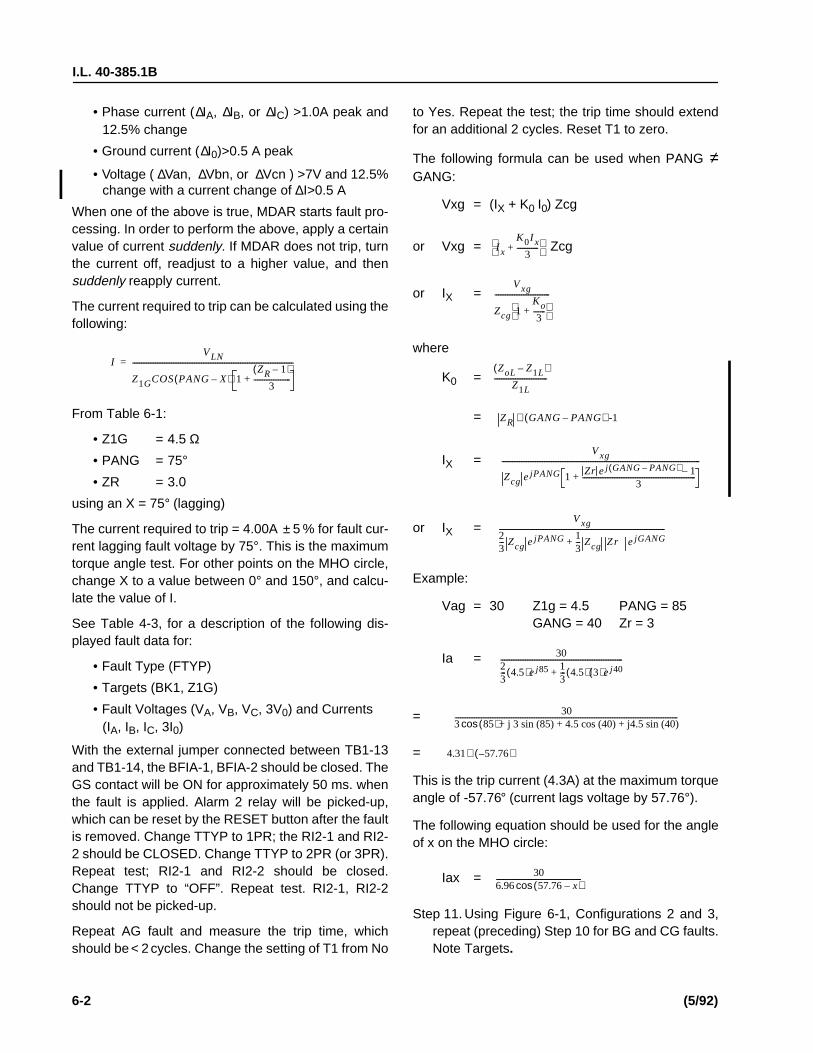
I.L. 40-385.1B
6-2 (5/92)
• Phase current (∆IA, ∆IB, or ∆IC) >1.0A peak and12.5% change
• Ground current (∆I0)>0.5 A peak
• Voltage ( ∆Van, ∆Vbn, or ∆Vcn ) >7V and 12.5%change with a current change of ∆I>0.5 A
When one of the above is true, MDAR starts fault pro-cessing. In order to perform the above, apply a certainvalue of current suddenly. If MDAR does not trip, turnthe current off, readjust to a higher value, and thensuddenly reapply current.
The current required to trip can be calculated using thefollowing:
From Table 6-1:
• Z1G = 4.5 Ω• PANG = 75°• ZR = 3.0
using an X = 75° (lagging)
The current required to trip = 4.00A ± 5 % for fault cur-rent lagging fault voltage by 75°. This is the maximumtorque angle test. For other points on the MHO circle,change X to a value between 0° and 150°, and calcu-late the value of I.
See Table 4-3, for a description of the following dis-played fault data for:
• Fault Type (FTYP)
• Targets (BK1, Z1G)
• Fault Voltages (VA, VB, VC, 3V0) and Currents(IA, IB, IC, 3I0)
With the external jumper connected between TB1-13and TB1-14, the BFIA-1, BFIA-2 should be closed. TheGS contact will be ON for approximately 50 ms. whenthe fault is applied. Alarm 2 relay will be picked-up,which can be reset by the RESET button after the faultis removed. Change TTYP to 1PR; the RI2-1 and RI2-2 should be CLOSED. Change TTYP to 2PR (or 3PR).Repeat test; RI2-1 and RI2-2 should be closed.Change TTYP to “OFF”. Repeat test. RI2-1, RI2-2should not be picked-up.
Repeat AG fault and measure the trip time, whichshould be < 2 cycles. Change the setting of T1 from No
IVLN
Z1GCOS PANG X–( ) 1ZR 1–( )
3---------------------+
-------------------------------------------------------------------------------------------=
to Yes. Repeat the test; the trip time should extendfor an additional 2 cycles. Reset T1 to zero.
The following formula can be used when PANG ≠GANG:
Vxg = (IX + K0 I0) Zcg
or Vxg = Zcg
or IX =
where
K0 =
=
IX =
or IX =
Example:
Vag = 30 Z1g = 4.5 PANG = 85GANG = 40 Zr = 3
Ia =
=
=
This is the trip current (4.3A) at the maximum torqueangle of -57.76° (current lags voltage by 57.76°).
The following equation should be used for the angleof x on the MHO circle:
Iax =
Step 11. Using Figure 6-1, Configurations 2 and 3,repeat (preceding) Step 10 for BG and CG faults.Note Targets.
I x
K0I x3
------------+
Vxg
Zcg 1Ko3
-------+
-------------------------------
ZoL Z1L–( )Z1L
------------------------------
ZR GANG PANG–( ) -1∠
Vxg
Zcg ejPANG 1 Zr ej GANG PANG–( ) 1–3
----------------------------------------------------------------+
----------------------------------------------------------------------------------------------------------------
Vxg23--- Zcg ejPANG 1
3--- Zcg Zr ejGANG+
----------------------------------------------------------------------------------------------
3023--- 4.5( )ej85 1
3--- 4.5( ) 3( )ej40+
---------------------------------------------------------------------
303 85( )+ j 3 sin (85) + 4.5 cos (40) + j4.5 sin (40)cos------------------------------------------------------------------------------------------------------------------------------
4.31 57.76–( )∠
306.96 57.76 x–( )cos------------------------------------------------

I.L. 40-385.1B
(5/92) 6-3
1.1.4 Zone 1 Test/Three-Phase
Step 12. Using Figure 6-2, connect current and volt-age circuits and apply:
• VAN = 30V ∠0° IA = 6.67 ∠−75°
• VBN = 30V ∠−120° IB = 6.67 ∠−195°
• VCN = 30V ∠120° IC = 6.67 ∠+45°
Using a value of x = 75° (lagging), the current re-quired to trip is calculated as follows (Note Targets):
Since V2.00 uses IA + IB + IC to calculate 3I0, a bal-
anced 3-phase current source is recommended tobe used for this test (3I0 = 0). Figure 6-2 gives a con-
cept of the test. If a Doble or Multi-Amp test set isused, be sure to synchronize the 3-phase currents.If possible, use a multi-trace storage scope to verifythe waveforms of IA, IB and IC.
In order to plot the MHO circle for different input an-gle (X), the setting of RT (and RU, if OSB option isincluded) should be at maximum (15 ohms). The RTsetting is used for load restriction. (Refer to OSB testfor detailed information.) Set TTYP = 3PR. Repeattest; RI2-1 and RI2-2 should be closed. For TTYP =OFF, or 1PR, or 2PR repeat the test. RI2-1 and RI2-2 should be open.
1.1.5 Zone 1 Test/Phase-To-Phase
Step 13. Two methods can be used for this test.
a. Using T-connection (with Doble or Multi-AmpTest Unit; refer to Figure 6-3 for external terminalconnection and configuration 1.
• VA = 1/2 VF @ 0°
• VB = 1/2 VF @ 180°
• VC = 3/2 (70) = 105V @ 90° lead
Using VF = VA-VB = 30V
• VA = 15V @ 0°
• VB = 15V @ 180°
IVLN
Z1P PANG X–( )cos----------------------------------------------------- = 6.67A 5%±=
NOTE: Current (I A) required to trip = 3.33A ± 5%,with an angle of -75 degrees.
BC CA
VAN = 105 ∠90° VAN = 15 ∠180°VBN = 15 ∠0° VBN = 105 ∠90°VCN = 15 ∠180° VCN = 15 ∠0°IF = 3.33 ∠-75° IF = 3.33 ∠−75°
The following table is for BC and CA fault tests whenthe T-connection is used:
b. Using Y-connection
NOTE: This test is actually for φφG testing (seeFigure 6-3, configuration 1).
VAN = VF
VBN = VF
VCN =
or
VAN = 17.3
VBN = 17.3
VCN = 96.4
For either T or Y connection, using a value of x = 75°(lagging), current required to trip:
From Table 6-1:
• Z1P = 4.5 Ω
• PANG = 75°
For Y-connection only, current (IA) required to trip =3.33A ±5%, with an angle of -45°, because Ian hasalready lagged VF (Vab) by 30°. Review all targets.
NOTE: The accuracy of the voltage reading inthe metering mode is between 1 and 77Vrms. The inaccurate reading on V CNwill not affect the results of the test.
12---
2
3------- 0°∠
12---
2
3------- 120°–∠
32--- 70 VAN
2 12---VF
2––×
120°∠
0°∠
120°–∠
120°∠
IVF
2Z1P PANG X–( )cos---------------------------------------------------------=

I.L. 40-385.1B
6-4 (5/92)
The reclose contacts (RI2-1 and RI2-2) should beclosed for setting of TTYP = 2PR or 3PR, and shouldbe open for TTYP = OFF or 1PR.
Step 14. Repeat Step 13 for both BC and CA faults.Use the following voltages for each fault type:
BC CA
V V
V V
V V
1.1.6 Zone 2 Tests
Step 15. Press the DISPLAY SELECT pushbuttonuntil the SETTINGS mode LED is displayed.Change the setting values to:
• Z1P = “OUT” (Zone 1 phase value)
• Z1G = “OUT” (Zone 1 ground distance)
• Z2P = 4.5 Ω (Zone 2 phase value)
• T2P = 1.0 sec (Zone 2 phase timer)
• Z2G = 4.5 Ω (Zone 2 ground value)
• T2G = 1.5 sec (Zone 2 ground timer)
• Z2RI = “YES” (Zone 2 reclosing)
• TTYP = “3PR” (Reclosing mode)
Step 16. Perform Steps 10 thru 14 (above) for Zone2 only, using delayed trip times according to thezone 2 phase timer (T2P), and the Zone 2 groundtimer (T2G). Tolerances for T2P and T2G are 5%for an input current that is 10% above the calcu-lated value.
Repeat Step 10.The RI2 contacts 1 and 2 shouldbe closed, and the RB contacts 1 and 2 should beopen. Reset Z2RI to “NO”.
Repeat Step 10 again. The RI2 contacts 1 and 2should be open and the RB contacts 1 and 2should be closed.
Change the settings of T2G and T2P to BLK.Zone 2 should not be tripped for any type of fault.
1.1.7 Zone 3 Tests
Step 17. Press the DISPLAY SELECT pushbuttonuntil the SETTINGS mode LED is displayed.Change the setting values to:
• Z2P = “OUT” (Zone 2 phase value)
• Z2G = “OUT” (Zone 2 ground distance)
• Z3P = 4.5 Ω (Zone 3 phase value)
• T3P = 2.0 sec (Zone 3 phase timer)
• Z3G = 4.5 Ω (Zone 3 ground value)
• T3G = 2.5 sec (Zone 3 ground timer)
• Z3FR = “FWD” (Zone 3 direction)
• Z3RI = “YES” (RI = Z3T)
• TTYP = “3PR” (Reclosing Mode)
Step 18. Perform preceding steps 10 thru 14 forZone 3 only, using delayed trip times accordingto the Zone 3 phase timer (T3P), and the Zone 3ground timer (T3G). Tolerances for T3P and T3Gare ± 5% for an input current that is 10% abovethe calculated value.
Repeat Step 10. The RI2 contacts 1 and 2 shouldbe closed, and the RB contacts 1 and 2 should beopen. Reset Z3RI to “NO”.
Repeat Step 10 again. The RI2 contacts 1 and 2should be open and the RB contacts 1 and 2should be closed.
Step 19. Set Z3FR = REV, then repeat Step 10, ex-cept apply AG reversed fault (i.e., Ia leads Van by105°). The relay should trip, at Ia = 4.2A, in 2.5seconds. Reset Z3FR to “FWD”.
NOTE: For customers who use a computer totest the relays, or use their own settingsfor maintenance, refer to the followingexample to calculate and determine tripcurrents; set the relay as follows:
Z1P = ZIG = 4.5 T1 = 0
Z2P = Z2G = 6.0 T2P= T2G = 0.2
Z3P = Z3G = 9.0 T3P= T3G = 0.3
PANG = GANG = 75o ZR = 3
a. Single-Phase-to-Ground Fault
Use the equation in Step 10, and the following inputvoltages:
VAN 96.4 120°∠= VAN 17.3 120°–∠=
VBN 17.3 0°∠= VBN 96.4 120°∠=
VCN 17.3 120°–∠= VCN 17.3 0°∠=
I F 3.33 45°–∠= I F 3.33 45°–∠=
VAN 45 0°∠ VLN= =
VBN 70 120°–∠=
VCN 70 120°∠=

I.L. 40-385.1B
(5/92) 6-5
voltages are necessary as directionalreference. The ITG and ITP will automat-ically become non-directional over-current units if the setting of LOPB isYES and at least one input voltage iszero volts (e.g., LOPB = YES in the me-tering mode).
Step 21. Using Figure 6-1, configuration #1, to con-nect currents and voltages, apply AG fault asshown in Step 1.1.3. The MDAR should trip at Ia= 5 Amps ± 5 % with a target of ITG-AG. For re-versed fault, apply 10A reversed fault current(i.e., Ia leads Van by 135° for Y-connection, or
105° for T-connection). The relay should not trip.
Step 22. Using Figure 6-3, to connect currents andvoltages, apply AB fault as shown in Step 1.1.5.The MDAR should trip at Iab = 10 Amps ±5%,with a target of ITP - AB. Apply a 15A reversedfault current (i.e., Ia leads Vab by 135° for Y-con-nection or 105° for T-connection). The relayshould not trip.
1.1.9 Ground Backup (GB) Test
Step 23. Use the SETTINGS mode and change thefollowing settings:
• ITP = “OUT”
• ITG = “OUT”
• GBCV = CO-8
• GBPU = .5
• GDIR = “NO”
• GTC = 24
NOTE: The note in Step 20 applies to the GBtest. The GB can be set to directionalground overcurrent. For loss-of-poten-tial condition, GB will be converted tonon-directional, automatically, regard-less of the GDIR=YES setting.
Using Figure 6-1, apply A-G fault of 4.1A to MDAR.Trip time is determined as follows:
(TMSEC) =
where
(3IOF is zero sequence fault current.)
478 41223I 0 1.27–-------------------------+
GTC24
------------
3I 0
3I OFGBPU-----------------=
The single-phase trip currents for Zone 1, Zone 2,and Zone 3 at the maximum torque angle
are 6.0A, 4.5A and 3.0A, respectively.
b. Phase-to-Phase Fault
Use the T-connection and the equation in step 13.Apply the following input voltages:
The single-phase trip currents for Zone 1, Zone 2and Zone 3 at the maximum torque angle
are 4A, 3A and 2A, respectively.
c. Three-Phase Fault
Use the equation in Step 12 with the following inputvoltages:
The three-phase trip currents for Zone 1, Zone 2 andZone 3 at the maximum torque angles
should be 6.0A, 4.5A and 3.0A, respectively.
1.1.8 Instantaneous Overcurrent (High-SetTrip)
Step 20. Using the SETTINGS mode, change thefollowing settings:
ITP = 10A LOPB = “NO”
ITG = 5A Z3G = “OUT”
Z3P = “OUT”
NOTE: The High-Set ground overcurrent (ITG)and phase overcurrent (ITP) are super-vised by Forward Directional Groundunit (FDOG) and Forward DirectionalPhase unit (FDOP), respectively. In or-der to test the High-Set trip, the 3 φ
I A 75°∠( )
VAN 18 0°∠ 12---VF= =
VBN 18 180°–∠ 12---VF= =
VCN 105 90°∠=
I AB 75°–∠( )
VAN 27 0°∠ VLN= =
VBN 27 120°–∠=
VCN 27 120°∠=
I A 75°, I B 195°, I C +45°∠–∠–∠( )

I.L. 40-385.1B
6-6 (5/92)
(TMSEC) =
TMSEC = 1073 msec
= 1.073 sec ± 5 % to trip
For values of 3I0 between 1.0 and 1.5, the following
equation would apply:
(TMSEC) =
The following equation can be used to calculate thetrip time for all CO curves from CO-2 to CO-11:
T(sec) =
T(sec) =
where
GBPU = Pickup current setting (0.5 to 4.0A).
GTC = Time curve dial setting (1 to 63).
To, K, C, P and R are constants, and are shown inTable 6-2.
Step 24. For a Zero Sequence Directional unit (DI-RU = ZSEQ), the tripping direction of MDAR is:the angle of 3I0 leads 3V0 between +30° and
+210°. Change the setting of GDIR to “YES”. Ap-ply AG fault as shown in preceding Step 10, Fig-ure 6-1. The relay should trip at the followingangles:
• +28°
• -60° (± 88°)
• -148°
The relay should not trip at the angles of:
• +32°
• +120° (± 88°)
• -152°
For a Negative Sequence Directional Unit (DIRU =NSEQ), the tripping direction of MDAR is: I2 leads V2
by a value between +8° and +188°. The relay shouldtrip at the following angles:
• +3°
• -82° (± 85°)
• -167°
The relay should not trip at the angles of:
• +13°
• +98° (± 85°)
• +183°
Step 25. For a dual polarizing ground directionalunit (DIRU = DUAL) test, connect the test circuit
shown in Figure 6-4; apply lp 1.0A to ter-minals 12 (+) and 11(-), and apply a balanced 3-phase voltage (70V) to Va, Vb, Vc, and Vn. ApplyIa = 4A to terminals 6(+) and 5(-).
NOTE: In order to eliminate the voltage polariz-ing effect, make sure the voltages arefinely balanced so that 3V0 is less than1.0 volt.
The relay should trip at the following angles:
• -3°
• -90o ( ± 87°)
• -177°
The relay should not trip at the following angles:
• +3°
• +90° ( ±87°)
• +177°
1.1.10 CIF, STUB, Iom, IL and LV Tests
Step 26. Set the relay per Table 6-1. Change thefollowing settings: Iom = 3, IL = 2, CIF = CIFT,and connect a rated dc voltage to 52b, betweenTB5/3 (+) and TB5/4 (-). Apply an AG fault asshown in Step 10 (Figure 6-1). The relay shouldtrip at Ia = 2A (IL) with CIF target. Change IL set-ting from 2 to 3.5A and repeat the test shown inStep 26. The relay should trip at Ia = 3A (Iom) withCIF target.
Step 27. LV setting test. Set LV = 60 and with IAN =4A, apply AG fault as shown in Step 10. The CIFtrip should be for VAN <60 Vrms ± 5%.
Step 28. For STUB Bus Protection (SBP), checkthe blue jumpers on the Interconnect module.
478 41224.1/0.5 -1.27------------------------------+
2424------
9200( )3I 0 1–-----------------
GTC24
------------× CO 8 only–( )
T0K
3I 0 C–( )p---------------------------+
GTC24 000,------------------ for 3I 0 1.5≥( )×
R3I 0 1–( )----------------------
GTC24 000,------------------× for 1 3I 0 1.5< <( )
3I 0
3I OFGBPU-----------------=
90°–∠

I.L. 40-385.1B
(5/92) 6-7
JMP7 and 9 should be IN; JMP13 should be atthe rated voltage position. Select CIF = STUB.Disconnect the voltage from 52b and connect itto terminals TB5/13(+) and TB5/14(-).
NOTE: Make sure the jumpers (JMP8 andJMP10) are not IN before applying thevoltage to TB5/13(+) and TB5/14(-).
Apply IA = 4A. The STUB bus trips for any VAN volt-
age with a target of CIF. Disconnect the voltage fromSBP and reset Iom = IL = 0.5 and CIF = NO.
1.1.11 Loss-of-Potential (LOP) Test
Step 29. For Load Loss Trip (LLT), set:
LLT = Yes
Z2P = Z2G = 4.5 ohms
T2P = T2G = 2.99 sec (or BLK)
Apply:
Va = 30
Vb = 70
Vc = 70
Ia = 3.5
Ib = 1
Ic = 1
Suddenly increase Ia from 3.5 to 4.5A and then turnIb OFF immediately. The relay should trip with LLT
target. The trip is accelerated due to the pickup ofZone 2 and the setting of LLT = YES.
Change the setting of LLT = FDOG and the inputcurrent Ia from 0.5 to 1.5A; then turn Ib OFF imme-
diately. The relay should trip with a target of LLT.The trip is due to the pickup of FDOG and setting ofLLT = FDOG.
Reset: LLT = NO
Z2P = Z2G = OUT
T2P = T2G = BLK
Step 30. Disconnect all current inputs. Connect 3balanced voltages of 70 Vac to Van, Vbn, and Vcn.Using the SETTINGS mode, change the setting:LOPB = YES.
NOTE: The “RELAY IN SERVICE” LED will notbe turned “OFF” for the condition of set-ting LOPB = Yes, but Zone 1, 2, 3 and pi-lot distance units will be blocked and allovercurrent units (GB, ITP, and ITG) willbe converted to non-directional opera-tion.
LOPB will be set if the following logic is satisfied:
• one (or more) input voltages (VAN, VBN or VCN)are detected (as <7 Vrms) without ∆I change,or
• a 3Vo (> 7Vrms) is detected with 3Io <Ios
Apply VAN, VBN and VCN rated voltage toMDAR. Scroll the LED to metering mode; the dis-play shows LOPB = NO. Reduce VAN to 62 Vrms(e.g., 3V0 = 8V). After approximately 0.5 sec-
onds, the display shows LOPB = YES and theform C failure alarm (AL1) contact is also de-energized.
Step 31. Set the relay as follows:
Z1P = 4.5 GBCV = CO-8
Z1G = 4.5 GBPU = 0.5
ITP = 10 GDIR = YES
ITG = 5 GTC = 24
Repeat Step 10 (AG Fault) with IAN = 4.5A. While
in the metering mode, be sure that LOPB = YESbefore the fault current is applied. The relayshould be tripped with a target of GB. Apply 5.5A;the relay should be tripped with a target of ITG.Repeat the test with a reversed AG Fault; the re-lay will trip. Reset LOPB = NO; the relay shouldnot trip for the reversed fault. Set LOPB = YES.
Step 32. Apply a balanced three-phase voltage (70Vrms) and current (3A). Turn off Va; the relayshould not trip. Reset LOPB to NO.
1.1.12 Loss-Of-Current (LOI) Test
Step 33. Set LOIB to YES and IOM = 1.0A. Apply a
balanced three-phase voltage (70 Vrms). Con-nect the current inputs per Figure 6-1, and applya single phase current of 1.1A to IA. After approx-
imately 0.5 seconds, the “Relay In Service” LEDwill be turned off, and the Form C failure alarm(AL1) contact will be dropped out (deenergized)indicating a failure condition.
0°∠
120°–∠
120°∠
75°–∠
120°–∠
+120°∠

I.L. 40-385.1B
6-8 (5/92)
Step 34. Increase IA to 1.5A. Depress the DIS-
PLAY SELECT pushbutton and change to themetering (VOLTS/AMPS/ANGLE) mode. PressFUNCTION RAISE pushbutton until the LOI dis-play is shown. The value should indicate “YES”.Suddenly turn OFF VA voltage; the relay should
not be tripped within 500 ms. It may operate after500 ms if a delta I is detected by the relay.Change the setting of LOIB from YES to NO.
1.1.13 Output Contact Test
Step 35. The purpose of this test is to check thehardware connections and relay contacts. It isdesigned for a bench test only. Remove JMP3(spare on the Microprocessor PC Board) andplace it in the JMP5 position. Open the red-han-dled FT switch (Trip and Breaker Failure Initiate)in order to avoid the undesired trip.
NOTE: The red-handled FT switch (#13) controlsthe dc supply of BFI, RI2 and the option-al RI1 relays. In order to test these relaysin the system, the external wiring shouldbe disconnected to avoid undesired re-closing or trip. For relays without FTswitches, do not perform the OutputContact tests using the relay system.
Change the LED mode to “TEST” and select thetripping function field and the desired contact inthe value field. Push the ENTER button; the EN-TER LED should be “ON”. The corresponding re-lay should operate when the ENTER button ispressed. The following contacts can be tested:
• TRIP
• BFI
• RI1 (optional)
• RI2
• RB
• AL1 (with three balanced voltages applied)
• AL2
• GS
• SEND (optional)
• STOP (optional)
Remove JMP5 and replace it on JMP3.
Step 36. This completes the basic AcceptanceTest for the MDAR Non-Pilot system. (See sub-
sequent segment for optional Single Pole Tripand Out-of-Step Block tests.)
1.2 PILOT PERFORMANCE TESTS
To prepare the MDAR relay assembly for Pilot Ac-ceptance Tests, connect the MDAR per Figure 6-1,Configuration 1.
1.2.1 Front Panel Check
Step 1. Repeat steps 1 thru 6 in Non-Pilot Accep-tance Tests, except that in step 6, set values arein accordance with Table 6-3.
Step 2. Change the value settings, in Table 6-3,as follows:
• PLT YES • PLTP 6.0
• Z3FR REV • Z3P 6.0
• ZIP OUT • Z3G 6.0
• ZIG OUT • T3P BLK
• PLTG 6.0 • T3G BLK
The RBSW is always set at “YES” internally, re-gardless of the display shown by the remoteWRELCOM software.
NOTE: When the dc voltage is applied to TB5terminals, check jumper position on In-terconnect module for the appropriateselection.
Connect a rated dc voltage to PLT/ENA terminalsTB5/9(+) and TB5/10(-).
1.2.2 Blocking (BLK) Scheme
Step 3. Change the STYP setting to BLK. Apply arated dc voltage to RCVR #1 terminals TB5/7(+)and TB5/8(-). Check the metering mode for RX1= YES. Apply an AG fault as shown in Step 10 ofthe Non-Pilot Acceptance Test (i.e., Va = 30 voltsand Ia = 4 Amps). The trip A contacts should notbe closed. The CARRY SEND should be “open”and the CARRY STOP should be “closed”.
Step 4. Remove the dc voltage from RCVR #1and apply AG fault. Trip A contacts should be“closed” and the target should show “PLTG AG”.
Change the LED mode to “TEST” and select the“RS1” function. Push the ENTER button; the EN-TER LED should be “ON”. Repeat Step 4 with theENTER button depressed. The relay should nottrip.

I.L. 40-385.1B
(5/92) 6-9
Step 5. Apply AG reversed fault (i.e., Ia leads Va
by 105 degrees). The CARRY SEND contactsshould be “closed” and the CARRY STOP con-tacts should be “open”. (Ia should be > 3A for theZone 3 setting of 6 ohms.)
Step 6. Change the LED mode to TEST and se-lect the function “TK”. Push the ENTER button;the ENTER LED should be “ON” and the CARRYSEND contacts should be closed.
Step 7. In order to determine setting accuracy (6ohms), the forward directional ground unit mustbe disabled. Set FDGT = BLK. Repeat precedingStep 4 of the Pilot Acceptance Test, with a trip in-put current (Ia) of 3 Amps (±5%).
Step 8. Set the Forward Directional Ground Timer(FDGT) from 0 to 15 cycles. Repeat Step 4 withIa = 1.5 A. The relay should be tripped after the
delay time of FDGT.
NOTE: The FDOG trip is determined by the IOMsetting. It trips if 3I 0 >Iom and the forwardground directional unit picks up.
Step 9. In order to perform the Breaker FailureReclose Block Test, change the setting of FDGT= 0 and BFRB = NO. Repeat test Step 4; RB con-tacts (TB3/1 and TB3/2) should not close.Change BFRB to YES and repeat the test. TheRB contacts should be closed with a time delaybetween 150 ms and 200 ms.
NOTE: For Va = Vb = Vc = 0, Ia = Ib = Ic = 0, thesetting of OSB = YES, WFEN = NO, andthe input of 52b = OV, the carrier SENDcontacts will be closed. This is not desir-able, but occurs only on the test bench.If tested with the relay system, V = 0 andI = 0 mean that the 52b input is at a ratedvoltage which will stop the SEND signal.
1.2.3 PUTT or POTT Schemes
Step 10. Change the setting to STYP = PUTT (forunderreach scheme) or STYP = POTT (for over-reach scheme). In order to determine setting ac-curacy (6 ohms), the forward directional groundunit must be disabled. Set FDGT = BLK. Apply arated voltage to RCVR #1 terminals TB5/7(+) andTB5/8(-), and apply an AG fault as shown in Step10 of the Non-Pilot Acceptance Test. The tripcontact A should be closed at the input Ia = 3A
(± 5%); the target should show “PLTG AG”, andthe CARRY SEND contact should be “closed” forPOTT setting. Do not test carry STOP for POTTand PUTT schemes.
Step 11. Apply a reversed AG fault (Ia leads Va by
105°). The relay should not trip, and the CARRYSEND contact should stay “open”.
Step 12. Remove the voltage on RCVR #1. Apply aforward AG fault as shown in Step 10. The tripcontacts should remain “open” for Ia = 5A.
Step 13. Change the LED mode to TEST and se-lect the function “RS1”. Push the ENTER button;the ENTER LED should be “ON”. Repeat Step 12with the ENTER button depressed. The relayshould trip.
Step 14. Repeat steps 8 and 9 for FDGT and BFRBtests, by using Step 10 with Ia = 1.5 A.
1.2.4 Weakfeed Scheme
Step 15. This function is for POTT only. In additionto the setting changes in Step 2, change the fol-lowing settings:
• STYP POTT
• WFEN YES
• Z3G 4.5
• Z3P 4.5
• Z3FR REV
Apply a rated voltage to PLT/ENA terminals TB5/9(+) and TB5/10(-), also RCVR #1 terminals TB5/7(+) and TB5/8(-).
With Van = Vbn = Vcn = 70 Vrms applied (asshown in Figure 6-1), the relay should operatenormally.
NOTE: Do not apply fault current.
Turn Van “OFF”; the relay should trip with a target
of WFT, and the Carrier Send contact (TB4-1 andTB4-2) should close momentarily.
Reduce Van from 70 Vrms to 69Vrms and applya reverse AG fault current of 5A (i.e., Ia leads Vanby 105 degrees). Turn Van “OFF”; the relay
should not trip, and the Carrier Send contact(TB4-1 and TB4-2) should stay open.
Step 16. This completes the basic AcceptanceTest for the MDAR Pilot System. (See subse-

I.L. 40-385.1B
6-10 (5/92)
quent segments for optional Single Pole Triptest.)
1.3 SINGLE POLE TRIP (OPTION)ACCEPTANCE TESTS
Step 1. Set relay for Non-Pilot (per Table 6-1), orfor Pilot Systems (per Table 6-3). Check the 62Tsetting; it should be 5.000. For a Pilot System,change the setting to PLT = YES, and apply a rat-ed dc voltage to Pilot Enable terminals TB5/9(+)and TB5/10(-). Also apply a rated voltage toRCVR #1 terminals TB5/7(+) and TB5/8(-) if theSTYP = POTT or PUTT; set TTYP = SPR.
Apply AG fault as shown in this Appendix Section1.1.3, Step 10. The Trip A contacts (2FT-14/1-2and 3-4) should be closed. Repeat BG fault (forTrip B contact closures) and repeat CG-Fault (forTrip C contact closures).
1.3.1 Sound Phase Fault (SPF) and 62T Trip
Step 2. Apply a rated dc voltage to 52a terminalsTB5/1(+) and TB5/2(-) and to 52b terminals TB5/3(+) and TB5/4(-). Connect a WestinghouseLockout (WL) switch to the trip circuit.
Step 3. Apply a phase-to-phase fault (as shown inthis Appendix, segment 1.1.5, Step 13). Turn thefault current “ON” and “OFF”. The WL switch tripswith a target of SPF.
Step 4. Set the WL switch, immediately; it will tripagain with a target of 62T. Remove the voltagesfrom 52a and 52b.
1.3.2 Reclose (RI) Trip and Breaker Failure(BFI) Contacts
Step 5. Refer to the Non-Pilot Acceptance Testfor the single-phase-to-ground faults (Steps 10and 11), and to the three-phase fault (Step 12).The fault current should be 20% greater than thecalculated values for the tests in these steps. The“fault types” applied to the MDAR relay areshown in Table 6-4 (column 2). TTYP settingsare shown in column 1, whereas the results of RI,Trip, and BFI contacts are shown in columns 3, 4,and 5, respectively.
1.4 MDAR WITH OUT-OF-STEP BLOCKOPTION
Refer to Figure 6-5. The RT setting (21BI) is for theinner blinder and it is also used for three-phase fault
load restriction. The RU setting (21BO) is for the out-er blinder. If the setting of OSB is “YES”, and thepower swing stays inside the two parallel lines (RTand RU) for more than 50 ms, the three-phase faulttrip will be blocked until the timer (OSOT) times out.
Connect the test circuit as shown in Figure 6-2.
1.4.1 Condition OSB = NO
Step 1. Set the relay per Table 6-1, except for thefollowing settings:
Z1P = 10
Z1G = 10 T2P = 0.1
Z2P = 20 T2G = 0.1
Z2G = 20(Check: PANG = GANG = 75; RT = RU = 15; OSOT= 4000)
Step 2. Adjust the inputs as follows:
Step 3. Apply current IF of 2.35A ±5% suddenly.The relay should trip with a display of Z2P = ABC.
Step 4. Apply IF of 4.7A ±5% suddenly. The relayshould trip with a display of Z1P = ABC.
Step 5. Change the RT setting from 15 to 4. Re-peat Steps 3 and 4 (above). The relay should nottrip because the RT restricts the 3-phase faultcurrent.
NOTE: The trip current (IF) can be obtainedfrom the equation in test Step 12 (1.1.4Zone 1 Test/Three-Phase), with the pa-rameters:
VLN = 40 PANG = 75
Z1P = 10 (or Z2P = 20) X = 45
1.4.2 Condition OSB = YES
Change the OSB setting from NO to YES and RT =4, RU = 8.
Step 1. Change the LED to metering mode withthe display of OSB = NO.
Step 2. Apply a current IF of 2.7A ± 5% suddenly.The display should show OSB = YES for 4
Va 40 0°∠= I a I F 45°–∠=
Vb 40 120°–∠= I b I F 165°–∠=
Vc 40 120°∠= I c I F 75°∠=

I.L. 40-385.1B
(5/92) 6-11
seconds. This means the input power swing is in-side the outer blinder (2IBO). Repeat this test forIF = 4A and 4.75A. The display should show OSB= YES because the power swing is within twoblinders (2IBO and 2IBI).
Step 3. Apply a current of 4.5A and increase theIF to 5.5A immediately. The relay should trip witha display of Z2P = ABC (or Z1P = ABC). Thismeans the power swing stays inside the blindersfor more than 50 ms and then crosses over 21BI.For the current of 4.5A, Z1P or Z2P may pick up,but the relay trips after the OSOT timer times out.
Step 4. Apply IF of 5.25A suddenly (5% above thecalculated value). The relay should trip with a dis-play Z1P = ABC. The trip time should be<2 cycles.
2. MAINTENANCE QUALIFICATION TESTS
Maintenance qualification tests will determine if aparticular MDAR unit is working correctly.
2.1 Non-Pilot Maintenance Tests
It is recommended that either Doble or Multi-Amptest equipment should be used for this test. Refer toFigure 6-1 for the input voltage and current terminalconnection per configuration 1. Check all jumper po-sitions on the Interconnect module for rated dc volt-age.
2.1.1 Front Panel and Metering Check
Step 1. Turn on rated dc voltage. Check theFREQ setting; it should match the line frequencyand ct type (CTYP). Apply a balanced 3-phasevoltage (70 Vac); the Alarm 1 relay should be en-ergized. (Terminal TB4/7 and TB4/8 should bezero ohms.) The “Relay-in-Service” LED shouldbe “ON”.
Step 2. Press RESET pushbutton; the green LED(Volts/Amps/Angle) should be “ON”. Press theFUNCTION RAISE or FUNCTION LOWER push-button. Read the input voltages and their angles:
VAG = 70 ∠0°VBG = 70 ∠−120°VCG = 70 ∠120°with an error of ± 1 volt and ± 2°.
Step 3. Press the DISPLAY SELECT pushbutton,and note that the mode LED cycles thru the five
display modes. Release the pushbutton so thatthe SETTINGS mode LED is “ON”. Press theRAISE button to scroll thru the FUNCTIONFIELD to check the settings per Table 6-1 (non-pilot) or Table 6-3 (pilot). Change the setting, ifnecessary, by depressing the RAISE button inthe VALUE FIELD to the desired value and thenpressing the ENTER button.
Step 4. Press the RESET pushbutton (LED jumpsto Metering mode). Apply 3.0 A to IA with an angle
of -75°. Read IA from the front display; it should
be 3.0 ∠−75° with an error of 5% and ± 2°. Movethe input current from IA to IB or IC terminal.Read IB or IC to verify the transformer’s accuracy.
2.1.2 Impedance Accuracy Check
Step 5. Apply voltages to MDAR as follows:
VA = 30 ∠0°VB = 70 ∠-120°VC = 70 ∠120°
Apply forward fault current IA ∠-75° suddenly.
The relay should trip for IA = 4A ± 5%. The dis-
play should show “Z1G AG”.
Repeat for B and C phases per the following table:
Phase B Phase C
VA = 70 ∠120° VA = 70 ∠-120°VB = 30 ∠0° VB = 70 ∠120°VC = 70 ∠-120° VC = 30 ∠0°IB = 4 ∠-75° IC = 4 ∠-75°
2.1.3 Input Opto-Coupler Check
Step 6. External ResetApply an AG fault as shown in Step 5. The LASTFAULT LED should be flashing. Press the frontRESET pushbutton. The green LED (Volts/Amps/Angle) should be “ON”. Press the DIS-PLAY SELECT pushbutton and move the LEDback to LAST FAULT. The fault information “Z1GAG” should be displayed again. Apply a rated dcvoltage to terminals TB5/5 (+) and TB5/6(-). Thetarget data should be erased and the displayshould show “FTYP”. Remove the external resetvoltage.
Step 7. 52b TerminalsChange the CIF setting from “NO” to “CIFT”.

I.L. 40-385.1B
6-12 (5/92)
Apply an AG fault as shown in Step 5, with IA =
2 ∠−75°. The relay should not trip. Apply a rateddc voltage to terminals TB5/3 (+) and TB5/4 (-).Repeat the test. The relay should trip with a tar-get of CIF. Remove the 52b voltage and set CIFto STUB for the next test.
Step 8. Stub Bus Protection (SBP)Check the blue jumpers on the Interconnect mod-ule. Jumpers (JMP 7 and JMP 9) should be “IN”.JMP 13 should be at the rated voltage position.Apply a balanced 3-phase voltage (70 Vac and IA= 2A) using any angle. The relay should not trip.Apply a rated voltage to the SBP terminals: TB5/13(+) and TB5/14(-). The relay should trip with atarget of CIF. Change jumpers from JMP 7 and 9back to JMP 8 and 10; if the Stub Bus Protectionis not used. Reset CIF to “NO”.
2.1.4 Input Transformer (I P) Check
Step 9. Change the settings from Table 6-1 (orTable 6-3) as follows:
ZIP = OUTZIG = OUTDIRU = DUALGBCV = CO-8GBPU = 0.5GDIR = YESGTC = 24
For a dual polarizing ground directional unit (DI-RU = DUAL) test, connect the test circuit shownin Figure 6-4. Apply IP = 1.0A ∠−90° to terminals
12(+) and 11(-), and apply a balanced 3-phasevoltage (70 Vac) to Va, Vb, Vc, and Vn. Apply Ia= 4A to terminals 6 (+) and 5 (-). The relay shouldtrip at the following angles:
• -3°
• -90° (± 87°)
• -177°
The relay should not trip at the following angles:
• +3°
• +90° (± 87°)
• +177°
Change the settings back to Table 6-1 or 6-3.
2.1.5 Output Contact Test
Step 10. The purpose of this test is to check thehardware connections and relay contacts. It isdesigned for a bench test only. Remove JMP 3(spare on the Microprocessor PC Board) andplace it in the JMP 5 position.
Change the LED mode to “TEST” and select thetripping function field and the desired contact inthe value field. Push the ENTER button; the EN-TER LED should be “ON”. The corresponding re-lay should operate when the ENTER button ispressed. The following contacts can be tested:
• TRIP
• BFI
• RI1 (optional)
• RI2
• RB
• AL1 (with 3 balanced voltages)
• AL2
• GS
• SEND (optional)
• STOP (optional)
Remove JMP 5 and place it on JMP3.
2.2 Pilot Maintenance Test
Connect the MDAR per Figure 6-1, Configuration 1.
2.2.1 Basic Function Test
Step 1. Repeat Step 1 thru 10 in the Non-PilotMaintenance Test (2.1.1 thru 2.1.5).
2.2.2 Input Opto-Coupler Check
Step 2. PLT ENA Terminals Change the following settings from Table 6-3:
• PLT YES
• Z1P 0UT
• Z1G OUT
• PLTP OUT
• PLTG 6.0
• Z3P OUT
• Z3G 6.0
• T3P BLK
• T3G BLK
• Z3FR REV

I.L. 40-385.1B
(5/92) 6-13
a. Block Systems OnlyChange the STYP setting to BLK. Apply a for-ward fault, as shown in the Non-Pilot Mainte-nance Test, step 5. The relay should not trip.
Apply a rated dc voltage to PLT ENA terminalsTB 5/9(+) and TB 5/10(-). Repeat the test. The re-lay should trip.
b. POTT/PUTT Systems OnlyChange the STYP setting to POTT. Change theLED mode to TEST and select the function“RS1”. Push the ENTER button; the LED shouldbe “ON”. Apply a forward fault as shown in Non-Pilot Maintenance test, Step 5. With the ENTERbutton depressed, the relay should not trip. Applya rated dc voltage to terminals TB 5/9(+) and TB5/10(-). Repeat the test. The relay should trip.
Step 3. Receivers 1 and 2Apply a dc voltage to PLT ENA terminals TB 5/9(+) and TB5/10(-).
a. Block Systems OnlyChange the STYP setting to BLK. Apply a for-ward fault as shown in the Non-Pilot Mainte-nance test, Step 5. The relay should trip.
Apply a rated dc voltage to RCVR #1 terminalsTB 5/7 (+) and TB 5/8(-). Repeat the test. The re-lay should not trip. Move the dc voltage fromRCVR #1 to RCVR #2 terminals TB 5/11(+) andTB 5/12(-), and repeat this test for RCVR #2.
b. POTT/PUTT Systems OnlyChange the STYP setting to POTT. Apply a for-ward fault as shown in the Non-Pilot Mainte-nance test, Step 5. The relay should not trip.Apply a rated dc voltage to RCVR #1 terminalsTB 5/7(+) and TB 5/8(-). Repeat the test. The re-lay should trip.
Move the dc voltage from RCVR #1 to RCVR #2terminals TB 5/11(+) and TB 5/12(-), and repeatthis test for RCVR #2.
2.3 Single-Pole Trip Test
2.3.1 Output Contact Test (Phases B and C)
Step 1. Set relay for Non-Pilot systems (Table 6-1) or for Pilot systems (Table 6-3). Check the 62Tsetting; it should be 5.000.
For a Pilot system, change the PLT setting toYES, and apply rated dc voltage to Pilot enableterminals TB 5/9(+) and TB 5/10(-). Also, apply arated voltage to RCVR #1 terminals TB 5/7(+)and TB 5/8(-) if the STYP = POTT or PUTT; setTTYP = SPR.
Step 2. Repeat Non-Pilot Maintenance test, step5 for trip and BFI. Check the contact closures forTrip A, Trip B, Trip C and BFIA, BFIB, BFIC.
2.3.2 Input Opto-Coupler Check
Step 3. 52a TerminalsApply a rated voltage to 52b terminals TB 5/3(+)and TB 5/4(-) and then apply a rated voltage to52a terminals TB 5/1(+) and TB 5/2(-). The relayshould trip in 5 seconds with a display of 62T.
NOTE: When using sophisticatedautomated test equipment, to testMDAR, it should be noted thatsome conditions can be simulatedthat are not realistic. For instance,the equipment has the ability toremove three-phase voltageinstantaneously. This can causeerroneous test results.
For example, if a Zone 2 fault isapplied to MDAR but removed,before the Zone 2 trip decision, byinstantaneous removal of voltageand current, MDA may trip. This isdue to the total voltage collapseoccurring while MDA is in the faultmode. This does not represent atrue power system condition sincethe voltage and current cannotbecome zero instantaneously.

I.L. 40-385.1B
6-14(5/92)
Figure 6-1. Test Connection for Single-Phase-to-Ground Faults (Sheet 1 of 4)

I.L. 40-385.1B
(5/92)6-15
Figure 6-2. Test Connection for Three-Phase Faults
1502B51Sub 1
(Sheet 2 of 4)

I.L. 40-385.1B
6-16(5/92)
Figure 6-3.Test Connection for Phase-to-Phase Faults
1502B51Sub 1
(Sheet 3 of 4)

I.L. 40-385.1B
(5/92)6-17
Figure 6-4. Test Connection for Dual Polarizing Ground Directional Unit
1502B51
Sub 1
(Sheet 4 of 4)

I.L. 40-385.1B
6-18 (5/92)Figure 6-5. MDAR with Out-of-Step Block Option
9651A71Sub 1
22
21
20
19
18
17
16
15
14
13
12
11
10
9
8
7
6
5
4
3
2
1
-8 -7 -6 -5 -4 -3 -2 -1 1 2 3 4 5 6 7 8 9 10 11 12 13 14
R
Z2 = 20 ∠−75˚
Z1 = 10 ∠−75˚
jX
RT RU
Z = 17.3 ∠ -45˚(I = 2.35 Amps)
ZU = 16 ∠-45˚(I = 2.5 Amps)
Z = 8.7∠-45˚(I = 4.7 Amps)
ZT = 8.7∠-45˚(I = 5.0 Amps)
4 OHMS
8 OHMS
INPUTS: Va = 40 ∠0˚, Vb = 40 ∠-120˚, Vc = 40 ∠120˚
SETTINGS: PANG = 75˚, GANG = 75˚, ZR = 3
ABC FAULT WITH FAULT ANGLE OF 45˚
75˚ 45˚

I.L. 40-385.1B
(5/92) 6-19
TABLE 6-1. MDAR SETTINGS (NON-PILOT SYSTEM)
TABLE 6-2. TRIP TIME CONSTANTS FOR CO CURVES
Curve # To K C P R
CO2 111.99 735.00 0.675 1 501CO5 8196.67 13768.94 1.13 1 22705CO6 784.52 671.01 1.19 1 1475CO7 524.84 3120.56 0.8 1 2491CO8 477.84 4122.08 1.27 1 9200CO9 310.01 2756.06 1.35 1 9342CO11 110. 17640.00 0.5 2 8875
VERS 0OSC TRIPFDAT TRIPCTR 1000VTR 2000FREQ 60CTYP 5RP NOXPUD .5DTYP KMTTYP OFF62T 5.000 *Z1RI YESZ2RI NOZ3RI NOSTYP 3ZNPZ1P 4.5Z1G 4.5T1 NOZ2P OUTT2P 1.00Z2G OUTT2G 1.50Z3P OUTT3P 2.00GBPU 0.5T3G 2.50
Z3FR FWDPANG 75GANG 75ZR 3.0LV 60IL .5IOS .5IOM .5ITP OUTITG OUTOSB NO **OSOT 4000 **RT 15.00RU 15.00 **DIRU ZSEQGBCV OUTGTC 24GDIR YESCIF NOLOI NOAL2S NOLLT NOLOPB NOSETR NOTIME NO
* For Single-Pole trip option only.** For Out-of-Step Block option only.
NOTE: This MDAR settings table is for 60 Hz and 5A ct systems. For 1A ct, change Z1P, Z1G, Z2P, Z2G,Z3P, Z3G, RT, RU by multiplying a factor of 5, and all current values mentioned in the textshould be multiplied by a factor of 0.02.

I.L. 40-385.1B
6-20 (5/92)
TABLE 6-3. PRESENT MDAR SETTINGS (PILOT SYSTEM)
VERS 0OSC TRIPFDAT TRIPCTR 1000VTR 2000FREQ 60CTYP 5RP NOXPUD .5DTYP KMTTYP OFF62T 5.000*Z1RI YESZ2RI NOZ3RI NOPLT NOSTYP 3ZNPFDGT 0WFEN NO3TRM NOBLKT 0RBSW NOPLTP OUTPLTG 6.00Z1P 4.5Z1G 4.5T1 NOZ2P OUTT2P 1.00Z2G OUTT2G 1.50Z3P OUT
T3P 2.00Z3G OUTT3G 2.50Z3FR FWDPANG 75GANG 75ZR 3.0LV 60IL .5IOS .5IOM .5ITP OUTITG OUTOSB NO**OSOT 4000**RT 15.00RU 15.00**DIRU ZSEQGBCV OUTGBPU .5GTC 24GDIR YESCIF NOLLT NOLOPB NOLOIB NOAL2S NOSETR NOTIME NO
* For Single Pole Trip option only.** For Out-of-Step Block option only.
NOTE: This MDAR settings table is for 60 Hz and 5A ct systems. For 1A ct, change PLT, PLG, Z1P,Z1G, Z2P, Z2G, Z3P, Z3G, RT, RU by multiplying a factor of 5, and all current values men-tioned in the text should be multiplied by a factor of 0.02.

I.L. 40-385.1B
(5/92) 6-21
TABLE 6-4. FAULT TYPES APPLIED TO MDAR
SETTING FAULT TYPE OUT CONTACTSTTYP APPLIED RI TRIP BFI
OFF AG NO A,B,C A,B,CBG NO A,B,C A,B,CCG NO A,B,C A,B,CABC NO A,B,C A,B,C
1PR AG RI2 A,B,C A,B,CAB NO A,B,C A,B,CABC NO A,B,C A,B,C
2PR AG RI2 A,B,C A,B,CAB RI2 A,B,C A,B,CABC NO A,B,C A,B,C
3PR AG RI2 A,B,C A,B,CBG RI2 A,B,C A,B,CCG RI2 A,B,C A,B,CAB RI2 A,B,C A,B,CABC RI2 A,B,C A,B,C
SPR AG RI1 A ABG RI1 B BCG RI1 C CABC NO A,B,C A,B,C
SR3R AG RI1 A ABG RI1 B BCG RI1 C CABC RI2 A,B,C A,B,C

I.L. 40-385.1B
(5/92) Index-1
Numerics
1PR 3-Pole trip, reclosing on single-phase-to-ground faults . . . . . . . . .[3-7], [5-5], [5-6], [6-2], [6-3], [6-4]
21BI Inner Blinder for out-of-step application . . . . . . . . . . . . . . . . .[3-5], [3-8], [5-2], [6-10], [6-11]
21BO Outer Blinder for out-of-step application . . . . . . . . . . . . . . . .[3-8], [6-10]
21NP Pilot ground distance relay . . . . . . . . . . . . . . . . . . . . . . .[5-4]
21P Pilot distance relay . . . . . . . . . . . . . . . . . . . . . . . . . . .[5-4]
2PR 3-Pole trip, reclosing on all faults except 3f faults . . . . . . . . . . . .[2-3], [3-7], [5-5], [5-6], [6-2], [6-3], [6-4]
3PR 3-Pole trip, reclosing on all faults . . . . . . . . . . . . . . . . . . . .[2-3], [3-7], [3-9], [3-34], [5-5], [5-6], [6-2],[6-3], [6-4]
3PRN 3-Pole reclose enable for TTYP setting of 1PR or 2PR or3PR or SR3R . . . . . . . . . . . . . . . . . . . . . . . . . . . . . .[3-7], [3-26]
3PT 3-Pole Trip. . . . . . . . . . . . . . . . . . . . . . . . . . . . . . . .[2-3], [3-2], [3-8], [3-14], [3-34], [4-10][5-4]
3PTN 3-Pole trip enable for TTYP setting of 1PR or 2PR or 3PR or OFF . . .[3-26]
3RI 3-Pole Reclose Initiate, same as RI2 . . . . . . . . . . . . . . . . . .[4-10], [5-6]
3TRM Three Terminal Application . . . . . . . . . . . . . . . . . . . . . . .[3-15], [5-5]
3ZNP 3 Zone non-pilot system. . . . . . . . . . . . . . . . . . . . . . . . .[3-2], [3-3], [5-5]
52a Normally-open circuit breaker, auxiliary contact input. . . . . . . . . .[1-2], [3-2], [4-1], [6-10], [6-13]
52b Normally-closed circuit breaker, auxiliary contact input . . . . . . . . .[1-2], [3-5], [3-6], [3-10], [3-12], [3-15],[4-1]
62T Single phasing limit timer setting for SPT application . . . . . . . . . .[2-3], [3-9], [4-14], [5-4], [5-5], [6-10],[6-13], [6-20]
A
ADC Analog to Digital Converter (also A/D) . . . . . . . . . . . . . . . .
AG Phase A-to-Ground Fault . . . . . . . . . . . . . . . . . . . . . . . .[6-2], [6-4], [6-5], [6-6], [6-7], 6-8], [6-9],[6-10], [6-11], 6-12]
AL1 Alarm 1 for internal failure check or LOP/LOI . . . . . . . . . . . . . [3-4], [3-5], [3-7], [4-1], [6-7]
AL2 Alarm 2 (trip alarm) . . . . . . . . . . . . . . . . . . . . . . . . . . .[3-7], [4-1], [4-4], [4-16], [5-6],, [6-8],[6-12]
AL2S Trip alarm seal-in . . . . . . . . . . . . . . . . . . . . . . . . . . . [5-6]
B
BFI Breaker Failure Initiate . . . . . . . . . . . . . . . . . . . . . . . . .[1-2], [1-3], [3-7], [3-16], [4-1], [4-2], [4-4],[6-8], [6-10], [6-13]
BFIB Breaker Failure Initiate for Phase B for SPT option . . . . . . . . . . [6-13]
BFRB Breaker Failure Reclose Block for local and remote RB . . . . . . . [3-7], [4-10], [5-5], [6-9]
BG Phase B-to-Ground Fault . . . . . . . . . . . . . . . . . . . . . . . [4-14], [6-2], [6-10]
BLK Blocking system type . . . . . . . . . . . . . . . . . . . . . . . . . .[3-3], [3-9], [3-12], [3-15], [4-10], [5-5],[6-4], [6-7], [6-8],[6-9], [6-13]
BLKT Channel coordination timer setting in blocking system (in ms) . . . . [3-12], [5-4]
Section 7. INDEX TO NOMENCLATURE

I.L. 40-385.1B
Index-2 (5/92)
CCG Phase C-to-Ground Fault . . . . . . . . . . . . . . . . . . . . . . . [4-14], [6-2], [6-10]
CIF Close-Into-Fault . . . . . . . . . . . . . . . . . . . . . . . . . . . . [1-2], [2-2], [3-3], [3-5], [3-6], [3-10],[4-12], [5-1], [5-6], [6-6], [6-7], [6-11],[6-12]
CIFT Close-Into-Fault Trip . . . . . . . . . . . . . . . . . . . . . . . . . . [2-2], [3-5], [3-6], [5-6], [6-6], [6-11]
CONV Signal for A/D Converter . . . . . . . . . . . . . . . . . . . . . . . .
CR Carrier Receiver . . . . . . . . . . . . . . . . . . . . . . . . . . . . [3-10], [3-15]
ct Current Transformer . . . . . . . . . . . . . . . . . . . . . . . . . . [1-2]
CTR Current Transformer Ratio setting . . . . . . . . . . . . . . . . . . . [5-1], [5-4]
CTYP Current Transformer type setting (1A or 5A ct) . . . . . . . . . . . . [4-12], [5-4], [5-7], [6-1], [6-11]
DDIRU Directional control type (ZSEQ/NSEQ/DUAL) for FDOG & RDOG . . [3-4], [3-6], [3-7], [3-14], [5-6],
[6-1], [6-6], [6-12], [6-19], [6-20]
DKM Distance Unit (k meters) . . . . . . . . . . . . . . . . . . . . . . . . [4-14]
DMI Distance Unit (miles) . . . . . . . . . . . . . . . . . . . . . . . . . .
DTYP Distance unit selected for XPUD setting (KM or MI) . . . . . . . . . . [2-2], [4-10], [5-5]
DUAL Dual (V or I) Zero Sequence Polarizing Unit for FDOG or RDOG . . . [3-4], [3-6], [3-14], [4-11], [5-6],[6-1], [6-6], [6-12]
dVdI Delta V and Delta I - Line Disturbance. . . . . . . . . . . . . . . . . [3-9], [4-5]
EEEPROM Electrically Erasable Programmable Read Only Memory . . . . . . . [1-2], [1-5], [4-4]
EPROM Erasable Programmable Read Only Memory . . . . . . . . . . . . . [1-2], [1-4], [1-5]
FFANG Fault angle . . . . . . . . . . . . . . . . . . . . . . . . . . . . . . . [5-5]
FDAT Fault Data Initiation . . . . . . . . . . . . . . . . . . . . . . . . . . [3-8], [4-3], [4-4], [4-5], [5-4]
FDGT Forward Directional Ground Timer. . . . . . . . . . . . . . . . . . . [1-4], [2-2], [3-14], [5-5], [6-9]
FDOG Forward Directional Overcurrent Ground Unit determined bysetting if DIR . . . . . . . . . . . . . . . . . . . . . . . . . . . . . . [1-4], [3-2], [3-3], [3-5], [3-6], [3-7], [3-10],
[3-13], [3-14], [4-12], [5-2], [5-5], [5-6][6-5], [6-7], [6-9]
FDOP Forward Directional Overcurrent Phase . . . . . . . . . . . . . . . . [3-2], [3-7], [3-10], [3-13], [6-5]
FREQ Frequency setting selected (50Hz or 60Hz) . . . . . . . . . . . . . . [4-10], [5-4], [6-1], [6-11]
FTYP MDAR fault type . . . . . . . . . . . . . . . . . . . . . . . . . . . . [6-2], [6-11]
GGANG Zero sequence line impedance angle setting . . . . . . . . . . . . . [5-6], [6-2], [6-4], [6-10]
GB Ground backup trip target . . . . . . . . . . . . . . . . . . . . . . . [3-4], [3-5], [5-3], [5-5], [5-6], [6-5], [6-7]
GBCV Ground backup curve selection . . . . . . . . . . . . . . . . . . . . [3-4], [5-3], [6-5], [6-20]
GBPU Ground backup pickup multiplier setting . . . . . . . . . . . . . . . . [3-4], [5-3], [6-6]
GDIR Directional or Non-directional ground backup . . . . . . . . . . . . . [3-4], [5-3], [5-6], [6-5], [6-6]
GS General Start for External Record . . . . . . . . . . . . . . . . . . . [1-2], [3-6], [3-7], [6-2]
GTC Ground backup time dial setting . . . . . . . . . . . . . . . . . . . . [3-4], [5-3], [6-5], [6-6]

I.L. 40-385.1B
(5/92) Index-3
HHST High Speed Trip (Zone 1, PLT, ITP & ITG) . . . . . . . . . . . . . . [3-2], [3-3], [3-4], [3-5], [3-10]
IIF Fault current . . . . . . . . . . . . . . . . . . . . . . . . . . . . . . [6-10], [6-11]
IL Low-level phase current pickup value setting (Amp) . . . . . . . . . [2-2], [5-1], [6-6], [6-20]
INCOM INtegrated COMmunication Network providing 2-way serial . . . . . [1-1], [1-5]
IOM Median set ground current (3I0) pickup value setting (Amp) . . . . . [2-2], [3-3], [3-5], [3-10], [3-13], [4-12],[5-2], [5-7], [6-9]
IOS Low set ground current (3I0) pickup value setting (Amp) . . . . . . . [2-2], [3-14], [4-12], [5-1], [5-2], [5-7]
ITG Instantaneous ground (3I0) trip setting or trip target . . . . . . . . . [2-2], [3-4], [3-5], [4-12], [5-2], [5-5], [5-7],[6-5], [6-7], [6-20]
ITP Instantaneous phase trip setting or trip target . . . . . . . . . . . . . [2-2], [3-4], [3-5], [5-2], [5-5], [6-5], [6-7]
LLLT Load Loss Trip. . . . . . . . . . . . . . . . . . . . . . . . . . . . . [1-2], [3-6], [3-15], [5-6], [6-7]
LOI Loss of Current - 3I0 and not 3V0 . . . . . . . . . . . . . . . . . . . [2-2], [3-5], [3-14], [6-7], [6-8]
LOIB Loss of Current Block of tripping . . . . . . . . . . . . . . . . . . . [3-5], [5-6], [6-7], [6-8]
LOP Loss of Potential - 3V0 and not 3I0 . . . . . . . . . . . . . . . . . . [2-2], [3-4], [3-5], [3-14], [6-7]
LOPB Loss of Potential Block of tripping . . . . . . . . . . . . . . . . . . . [3-4], [3-5], [3-10], [5-6], [6-5], [6-7]
LP Pre-fault load angle . . . . . . . . . . . . . . . . . . . . . . . . . . [4-14]
LV Low voltage pickup setting for CIF and weakfeed application. . . . . [2-2], [3-5], [3-13], [5-5], [5-6], [6-6]
NNOVRAM Non-volatile read-write memory . . . . . . . . . . . . . . . . . . . . [1-2]
NSEQ Negative Sequence Quantity (V2 & I2) . . . . . . . . . . . . . . . . [3-4], [3-6], [3-14], [4-11], [5-6], [6-1], [6-6]
OOFF 3-Pole trip, no reclosing . . . . . . . . . . . . . . . . . . . . . . . . [3-7], [3-9], [3-12], [3-34], [4-1], [4-2],
[4-5], [5-5], [5-6], [6-2], [6-3], [6-4], [6-7],[6-8], [6-9], [6-10]
OOS Out-of-Step . . . . . . . . . . . . . . . . . . . . . . . . . . . . . . [3-16]
OSB Enable/Disable out-of-step blocking. . . . . . . . . . . . . . . . . . [2-3], [3-2], [3-7], [3-8], [3-10], [3-13],[3-15], [5-1], [5-2], [5-4],[6-3], [6-9],[6-10], [6-11]
OSC Oscillographic data . . . . . . . . . . . . . . . . . . . . . . . . . . [3-9], [4-5], [5-4]
OSOT Out-of-step block override timer (ms) . . . . . . . . . . . . . . . . . [5-4], [6-10], [6-11], [6-19], [6-20]
PP3PT 3-Pole trip due to phase fault for single-pole-trip option. . . . . . . . [3-26]
PAL Programmable Array Logic . . . . . . . . . . . . . . . . . . . . . .
PANG Positive sequence line impedance angle setting . . . . . . . . . . . [3-8], [5-2], [5-5], [6-2], [6-10]
PFAIL Power Supply Failure . . . . . . . . . . . . . . . . . . . . . . . . .
PFLC Pre-fault load current . . . . . . . . . . . . . . . . . . . . . . . . . [4-14]
PFLV Pre-fault load voltage . . . . . . . . . . . . . . . . . . . . . . . . . [4-14]
PLT/ENA Pilot enable (external switch) . . . . . . . . . . . . . . . . . . . . . [1-2], [3-28], [3-39], [4-7], [4-8], [6-8]

I.L. 40-385.1B
Index-4 (5/92)
PLTG Pilot ground distance setting (ohms) . . . . . . . . . . . . . . . . . . [3-5], [3-6], [3-9], [3-10], [3-11], [3-12],[3-13], [3-14], [4-12], [5-5], [5-7], [6-8],[6-9]
PLTP Pilot phase distance setting (ohms) . . . . . . . . . . . . . . . . . . [3-2], [3-8], [3-9], [3-10], [3-11], [3-12],[4-12], [5-5], [5-7], [6-8]
PONI Product Operated Network Interface. . . . . . . . . . . . . . . . . . [1-1], [2-3], [4-5]
POTT Permissive Overreaching Transfer Trip . . . . . . . . . . . . . . . . [3-9], [3-10], [3-11], [3-12], [3-13], [3-14],[3-15], [5-5], [6-9], [6-10], [6-13]
PROM Programmable Read Only Memory . . . . . . . . . . . . . . . . . . [1-2]
PSME Power Supply Monitor Enable . . . . . . . . . . . . . . . . . . . . .
PT Potential Transformer . . . . . . . . . . . . . . . . . . . . . . . . . [3-10], [4-10]
PU Per Unit representation for normalizing currents and voltages. . . . .
PUTT Permissive Underreaching Transfer Trip. . . . . . . . . . . . . . . . [3-9], [3-11], [3-15], [5-5], [6-9], [6-10],[6-13]
RRAM Random Access Memory . . . . . . . . . . . . . . . . . . . . . . . [1-2], [1-4], [1-5], [4-4]
RB Reclose Block . . . . . . . . . . . . . . . . . . . . . . . . . . . . . [1-2], [2-3], [3-5], [3-7], [3-8], [3-16], [4-1],[6-4], [6-9]
RBSW Reverse Block Switch (removed from setting table) . . . . . . . . . . [4-10], [6-8]
RCVR Receiver (external voltage or switch) . . . . . . . . . . . . . . . . . [3-10], [3-11], [3-13], [3-15], [3-28],[3-29],[6-8], [6-9], [6-10], [6-13]
RCVR #1 Receiver #1 (external voltage or switch) . . . . . . . . . . . . . . . . [1-2], [4-7], [4-8], [6-9], [6-13]
RCVR #2 Receiver #2 (external voltage or switch) . . . . . . . . . . . . . . . . [1-2], [4-7], [4-8], [6-13]
RDOG Reverse Direction Overcurrent Ground determined bythe setting of DIRU (ZSEQ/NSEQ/DUAL)[ . . . . . . . . . . . . . . . 3-2], [3-3], [3-5], [3-6], [3-7], [3-12], [3-13],
[3-14], [5-1]
REED B-1 Reed relay B-1 for trip seal-in . . . . . . . . . . . . . . . . . . . . .
REM Remote. . . . . . . . . . . . . . . . . . . . . . . . . . . . . . . . . [4-5], [4-13]
RI Reclose Initiate. . . . . . . . . . . . . . . . . . . . . . . . . . . . . [1-2], [3-11], [3-16], [4-1], [4-2], [4-4],[4-10], [5-5], [6-4], [6-10]
RI1 Reclose Initiate-1 for Single-Pole Reclose . . . . . . . . . . . . . . . [2-3], [3-7], [3-8], [3-34], [5-5], [5-6], [6-8]
RI2 Reclose Initiate-2 for 3-Pole Reclose . . . . . . . . . . . . . . . . . [2-3], [3-7], [3-8], [3-11], [3-34], [5-5],[5-6], [6-2], [6-3], [6-4], [6-8], [6-12]
ROM Read-Only-Memory . . . . . . . . . . . . . . . . . . . . . . . . . . [1-4], [1-5], [4-4]
RP Enable readouts in primary values . . . . . . . . . . . . . . . . . . . [4-3], [5-4], [6-1]
RS1 Test function for simulating receipt of receiver 1 and 2 inputs . . . . . [4-4], [6-8], [6-9], [6-13]
RS1 Test function for simulating receipt of receiver 1 input . . . . . . . . . [4-4], [6-8], [6-9], [6-13]
RS2 Test function for simulating receipt of receiver 1 and 2 inputs . . . . . [4-4]
RS2 Test function for simulating receipt of receiver 2 input . . . . . . . . . [4-4]
RT Inner blinder setting (ohms) for 3-phase load restriction . . . . . . . . [2-3], [3-8], [5-2], [6-3], [6-10], [6-19],[6-20]
RU Outer blinder setting (ohms) for out-of-step option. . . . . . . . . . . [2-3], [3-8], [5-2], [6-3], [6-10], [6-19],[6-20]
RX1 Pilot channel receiver #1 input, same as RCVR#1. . . . . . . . . . . [6-8], [4-13]
RX2 Pilot channel receiver #2 input, same as RCVR#2. . . . . . . . . . . [4-13]

I.L. 40-385.1B
(5/92) Index-5
SS3PT 3-pole trip due to SPF or 62T for single-pole-trip option . . . . . . .
SBP Stub bus protection (89b) . . . . . . . . . . . . . . . . . . . . . . . [1-2], [1-3], [3-5], [4-1], [4-4], [6-6],[6-7],[6-12]
SEL Chip select outputs . . . . . . . . . . . . . . . . . . . . . . . . . .
SEND Carrier send output . . . . . . . . . . . . . . . . . . . . . . . . . . [3-10], [3-11], [3-12], [3-13], [4-1], [6-8],[6-9]
SET Enable/Disable Remote/Local Setting. . . . . . . . . . . . . . . . . [3-14], [3-34], [4-5], [4-12]
SETR Enable INCOM remote setting capability . . . . . . . . . . . . . . . [4-5], [5-6]
SPF Sound phase fault trip . . . . . . . . . . . . . . . . . . . . . . . . . [6-10]
SPR Single-pole and 3-pole trip, single-pole reclosing only . . . . . . . . [2-3], [3-8], [3-9], [3-34], [5-5], [5-6],[6-10], [6-13]
SPT Single-Pole Trip for single-pole application . . . . . . . . . . . . . . [2-3], [3-2], [3-8], [3-9], [3-14], [3-16],[3-34], [4-10], [4-14], [5-5], [5-6]
SR3R Single-pole and 3-pole trip, reclosing for all faults. . . . . . . . . . . [3-8], [3-9], [3-34], [5-5], [5-6]
SRI Single-pole Reclose Initiate, same as RI-1 . . . . . . . . . . . . . . [4-10], [5-6]
STOP Carrier Stop Signal . . . . . . . . . . . . . . . . . . . . . . . . . . [4-1], [6-8], [6-9], [6-12]
STUB Stub Bus Protection same as SBP (89b) . . . . . . . . . . . . . . . [3-6], [3-14], [4-12], [5-6], [6-6], [6-7],[6-12]
STYP System type setting (3ZNP, Z1E, POTT, PUTT, BLK) . . . . . . . . [3-2], [3-3], [3-9], [3-10], [3-11], [3-12],[4-10], [5-5], [6-8], [6-9], [6-10], [6-13]
TT1 Zone 1 delay trip timer. . . . . . . . . . . . . . . . . . . . . . . . . [3-2], [5-5], [6-2]
T2G Zone 2 ground timer delay setting (seconds) . . . . . . . . . . . . . [3-3], [5-3], [5-5], [6-4], [6-7]
T2P Zone 2 phase timer delay setting (seconds) . . . . . . . . . . . . . [3-2], [3-3], [5-3], [5-5], [6-4]
T3G Zone 3 Ground Timer . . . . . . . . . . . . . . . . . . . . . . . . . [3-3], [5-4], [5-5], [6-4]
T3P Zone 3 Phase Timer. . . . . . . . . . . . . . . . . . . . . . . . . . [3-3], [5-4], [5-5], [6-4]
TBM Transient Block Memory. . . . . . . . . . . . . . . . . . . . . . . . [3-10], [3-11], [3-12], [3-13]
TDT Time Delay Trip (Zone 2, Zone 3 & GB). . . . . . . . . . . . . . . . [3-2], [3-3], [3-7], [3-10]
TK Transmitter Keying . . . . . . . . . . . . . . . . . . . . . . . . . . [3-11], [4-4], [6-9]
TRIP Trip Action . . . . . . . . . . . . . . . . . . . . . . . . . . . . . . . [2-3], [3-7], [3-8], [3-9], [3-14], [3-15],[3-16], [3-33], [3-34], [4-3], [4-4],[4-5],[4-10], [5-4], [6-8], [6-10], [6-12],[6-19], [6-20]
TRIPB Trip on Phase B . . . . . . . . . . . . . . . . . . . . . . . . . . . . [
TRIP B-1 Trip relay B-1 . . . . . . . . . . . . . . . . . . . . . . . . . . . . .
TRSL Trip Seal-in Trip signal and seal-in if trip current presented. . . . . . [3-2], [3-3], [3-7], [3-10], [3-16]
TTYP Trip Type, and reclose selection (1PR, 2PR, 3PR, etc.) . . . . . . . [2-3], [3-7], [3-8], [3-9], [3-34], [5-5], [5-6],[6-2], [6-3], [6-4], [6-10], [6-13]
UUBLK Unblock . . . . . . . . . . . . . . . . . . . . . . . . . . . . . . . . [3-15]
VBFI Power Supply voltage to Breaker Failure Initiate . . . . . . . . . . .

I.L. 40-385.1B
Index-6 (5/92)
V
VF Fault Voltage . . . . . . . . . . . . . . . . . . . . . . . . . . . . . . [6-3]
VLN Line-to-neutral voltage . . . . . . . . . . . . . . . . . . . . . . . . . [2-1], [6-10]
VTR Voltage Transformer Ratio . . . . . . . . . . . . . . . . . . . . . . . [5-1], [5-4]
W
WFEN Weakfeed Enable . . . . . . . . . . . . . . . . . . . . . . . . . . . [3-13], [3-15], [5-5], [6-9]
WFT Weakfeed Trip . . . . . . . . . . . . . . . . . . . . . . . . . . . . . [6-9]
X
X2(A) Pole Disagreement (SPT Application) . . . . . . . . . . . . . . . . . [3-26], [SD-2]
XPUD Reactance ohms per unit distance . . . . . . . . . . . . . . . . . . . [4-10], [5-5]
Z
Z1E Zone 1 Extension . . . . . . . . . . . . . . . . . . . . . . . . . . . [3-3], [3-4], [5-5]
Z1G Zone 1 Ground . . . . . . . . . . . . . . . . . . . . . . . . . . . . . [3-2], [3-3], [3-4], [3-5], [3-6], [3-9], [3-11],[3-14], [5-1], [5-2], [5-7], [6-2], [6-4],[6-11], [6-19], [6-20]
Z1P Zone 1 Phase . . . . . . . . . . . . . . . . . . . . . . . . . . . . . [3-2], [3-3], [3-4], [3-8], [3-11], [3-14],[5-1], [5-5], [6-4], [6-7], [6-10], [6-11],[6-19], [6-20]
Z1RI Zone 1 Reclose Initiate. . . . . . . . . . . . . . . . . . . . . . . . . [3-7], [3-11], [5-5], [5-6], [6-19], [6-20]
Z2G Zone 2 Ground . . . . . . . . . . . . . . . . . . . . . . . . . . . . . [3-3], [3-5], [3-6], [4-12], [5-1], [5-2], [5-5],[5-7], [6-4], [6-7], [6-19], [6-20]
Z2P Zone 2 Phase . . . . . . . . . . . . . . . . . . . . . . . . . . . . . [3-2], [3-3], [3-6], [3-8], [4-12], [5-1], [5-5],[5-7], [6-4], [6-10], [6-11], [6-19], [6-20]
Z2RI Zone 2 Reclose Initiate. . . . . . . . . . . . . . . . . . . . . . . . . [3-7], [5-5], [5-6], [6-4]
Z2T Zone 2 Timer . . . . . . . . . . . . . . . . . . . . . . . . . . . . . . [3-3], [3-4], [4-10]
Z2TR Zone 2 pickup or trip for OSC and target data . . . . . . . . . . . . . [3-8], [3-9], [4-4], [4-5], [4-10], [5-4]
Z2Z3 Zone 2 or Zone 3 Pickup or trip for OSC and target data . . . . . . . [3-8], [3-9], [4-10], [5-4]
Z3FR Zone 3 Forward/Reverse Setting. . . . . . . . . . . . . . . . . . . . [3-3], [3-11], [5-5], [6-4]
Z3G Zone 3 Ground . . . . . . . . . . . . . . . . . . . . . . . . . . . . . [3-3], [3-5], [3-9], [3-11], [3-12], [3-14],[3-15], [4-12], [5-1], [5-2], [5-5], [5-7],[6-4], [6-19], [6-20]
Z3P Zone 3 Phase . . . . . . . . . . . . . . . . . . . . . . . . . . . . . [3-2], [3-3], [3-8], [3-11], [3-12], [3-14],[3-15], [4-12], [5-1], [5-5], [5-7], [6-4],[6-5], [6-19], [6-20]
Z3RI Zone 3 Reclose Initiate. . . . . . . . . . . . . . . . . . . . . . . . . [3-7], [5-5], [5-6], [6-4]
Z3T Zone 3 Timer . . . . . . . . . . . . . . . . . . . . . . . . . . . . . . [3-3], [4-10], [6-4]
ZL Line Impedance . . . . . . . . . . . . . . . . . . . . . . . . . . . . [3-11]
ZR Ratio of zero and positive sequence impedances . . . . . . . . . . . [5-1], [5-6], [6-2]
ZSEQ Zero Sequence Quantity (3V0 & 3I0) . . . . . . . . . . . . . . . . . . [3-4], [3-6], [3-14], [5-6], [6-1], [6-6]

I.L. 40-385.1B
(5/92) SD-1
System Diagrams
Drawing Title Page No.
MDAR System Logic Diagram ..................... (sheet 1 of 4) ........................................................... SD-2
MDAR System Logic Diagram ..................... (sheet 2 of 4) ........................................................... SD-3
MDAR System Logic Diagram ..................... (sheet 3 of 4) ........................................................... SD-4
MDAR System Logic Diagram ..................... (sheet 4 of 4) ........................................................... SD-5
MDAR Block Diagram.................................. (sheet 1 of 1) ........................................................... SD-6

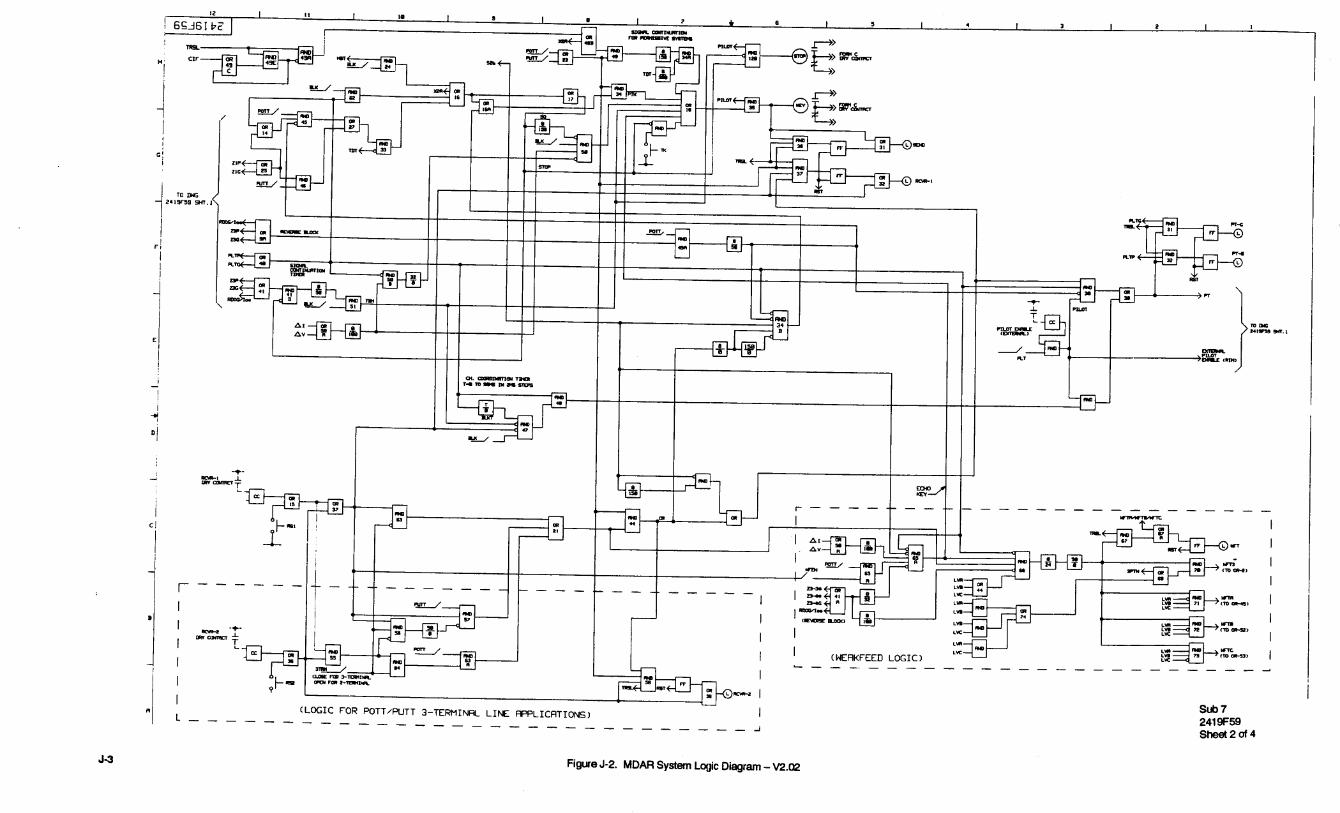


I.L. 40-385.1B
SD
-6(5/92)
Figure SD-2. MDAR Block Diagram (sheet 1 of 1)
Sub 11611C12