Embed Size (px)
Citation preview
Curtin Consultancy Services Ltd Curtin University
A.C.N. 008 751 175 GPO Box U 1987, Perth 6001 Kent Street, Bentley 6102 Western Australia Telephone (61 9) 351 3300 Internal 3300 Fax (61 9) 351 3290
DATE: 1 NOVEMBER 1994 REFERENCE: 1333/BD/HE REPORT ON: GLOW-WIRE TEST ON ELECTRICAL HEAT1NG FOILS TO AS2420 FOR: SAFE-T-HEAT PREPARED BY: ___________________________ DR H EREN Bsc, Msc, Phd, MIEE, MIEEE, CEng . Note to Client: You may reproduce this report, for publicity or other purposes, but only in full.

1.0 INTRODUCTION On the request of SAFE-T-HEAT Products Pty. Ltd. Glow wire tests were
conducted on 5 pieces of Electrical Heating Foils in accordance with AS242 standards.
AS2420 standards specify "Fire Test Methods for Solid Insulating Materials
and Non-Metallic Enclosures Used in Electrical Equipment". In these standards guidelines are given for the following tests:
1) Heat behavior test 2) Glow-wire test 3) Bad connection test 4) Surface tracking test 5) Needle-flame test
AS2420 standards clearly state that the fire hazard of electrical equipment may be controlled by the use of materials which do not ignite readily or by the use of designs which minimize the possibility of ignition or propagation of fire in the event of ignition. In general, an individual test will not assess the total fire hazard of equipment and also all the above listed tests may not be applicable to each individual item of equipment. Tests should be applied on the complete equipment but where this is not possible the tests may be applied to separate samples of the materials used within the equipment. It is clearly stated that the results from such tests may not correlate exactly with the performance of the actual equipment.
2.0 THE GLOW-WIRE TEST
The glow-wire test is concerned with Ignitability and Flame Propagation. It simulates the thermal stresses produced by heat or ignition sources. The glow-wire test may be conducted at different temperatures, these being:
a) C: determines the minimum level of resistance against ignition and
propagation of fire of all parts contributing to possible fire hazard. cons/reponsJ 13 3 3. doc
Curtin Consultancy Services Ltd Curtin University

b) 650 C: for enclosures of insulating materials in contact with current carrying parts.
c) 750 C: for various type equipment such as unattended portable
equipment, equipment used in mains and switchboard etc.
d) 850 C: for enclosures of insulating materials of equipment likely to be left unattended and are continuously energized or loaded for relatively long periods.
e) 960 C: for enclosures of insulating material of equipment with stringent
operating conditions and materials in contact with current carrying parts in mains and switch boards.
In the standards it is mentioned that it may be necessary to investigate further the fire hazard of the specimen under test by making tests with other ignition sources, eg needle-flame, bad -connection tests etc.
3.0 THE TESTS AND RESULTS
The glow-wire tests were conducted on the specimens in Accordance with AS2420 standards Appendix B. The results obtained are presented in Table 1.
The samples received were marked as follows:
1) Flexel (Safe-t-flex) Mark 4 Type C 240V 233W per m-. 2) Flexel (Safe-t-flex) Mark 4 Type CFR 240V 233W per m-
In all cases the probe penetrated the sample within 1 second of contact.
Flames noted appeared to be as a result of ignition of volatiles rather than base material under test. Also, very brief flicker of flames were noted.
cons/reports/1333.doc
Curtin Consultancy Services Ltd Curtin University

4.0 CONCLUSIONS
Six (6) Glow wire tests were conducted at 750ø and 850ø on five (5) samples of heating foils. In all cases no ignition of the base material was noted. However, base material of all samples melted within one second of application of the glow-wire probe. Other tests such as heat behavior or/and needle-flame tests may need to be considered to assess complete fire hazard potential.
cons/reports/13 3 3.doc
Curtin Consultancy Services Ltd Curtin University

Curtin Consultancy Services • Curtin University
table 3
TESTING TO AS2420-1987 SAMPLE 1
750°C SAMPLE 2
750°C SAMPLE 3
850° TIME ELAPSED AFTER APPLICATION OF HTE TIP UNTIL IGNITION OF THE TEST SPECIMEN
(TIME)
2sec
TIME ELAPSED AFTER THE APPLICATION OF TIP UNTIL IGNITION OF ANY SURROUNDING MATERIAL
(TIME)
TIME ELAPSED AFTER ANY IGNITION UTIL FLAMING OR GLOWING CEASES (DURING OR AFTER APPLICATION OF TIP)
(TIME)
2.5sec
MAXIMUM HEIGHT OF ANY FLAME AS IN AS24270-1987 B9 G IV
(HEIGHT)
1cm approx
ANY SCORCHING OF THE PARTICLE BOARD
(SCORCHING)
NO SCORCHING
ANY DISTORTION OF THE GLOW WIRE AND POSITION OF APPLICATION TO THE TEST SPECIMEN
(DISTORTION)
Immediate and complete penetration of samples
ORIENTATION OF THE GLOW WIRE AND POSITION OF APPLICATION TO THE TEST
Normal to surface
TEMPERATURE OF THE GLOW WIRE TIP
(TEMPERATURE)
750/751
749/750
850/851
APPLICATION TIME USED
(TIME) 30 Seconds from contact to withdrawal
ANY OTHER RELEVANT INFORMATION COMMENTS
Probe melted through material and was held at 7± 0.5mm penetration

REPORT ON
INGRESS PROTECTION RATING ON RADIANT HEAT ELEMENT PAD
FOR
SAFE T HEAT
MAY 1996

A.C.N. 008 751 175 GPO Box U 1987, Perth 6001 • Kent Street, Bentley 6102 • Western Australia Telephone (6 19) 351 3300 Internal 3300 Fax (6 19) 351 3290
DATE: May 1996
REFERENCE: 2296
REPORT ON: Ingress Protection Rating on Radiant Heat Element Pad
FOR: Safe T Heat
PREPARED BY: ____________________________ H Eren
BEng, MEng, PhD, MIEEE, MIEE, CEng
Note to client: You may reproduce this report, for publicity
or other purposes, but only in full.
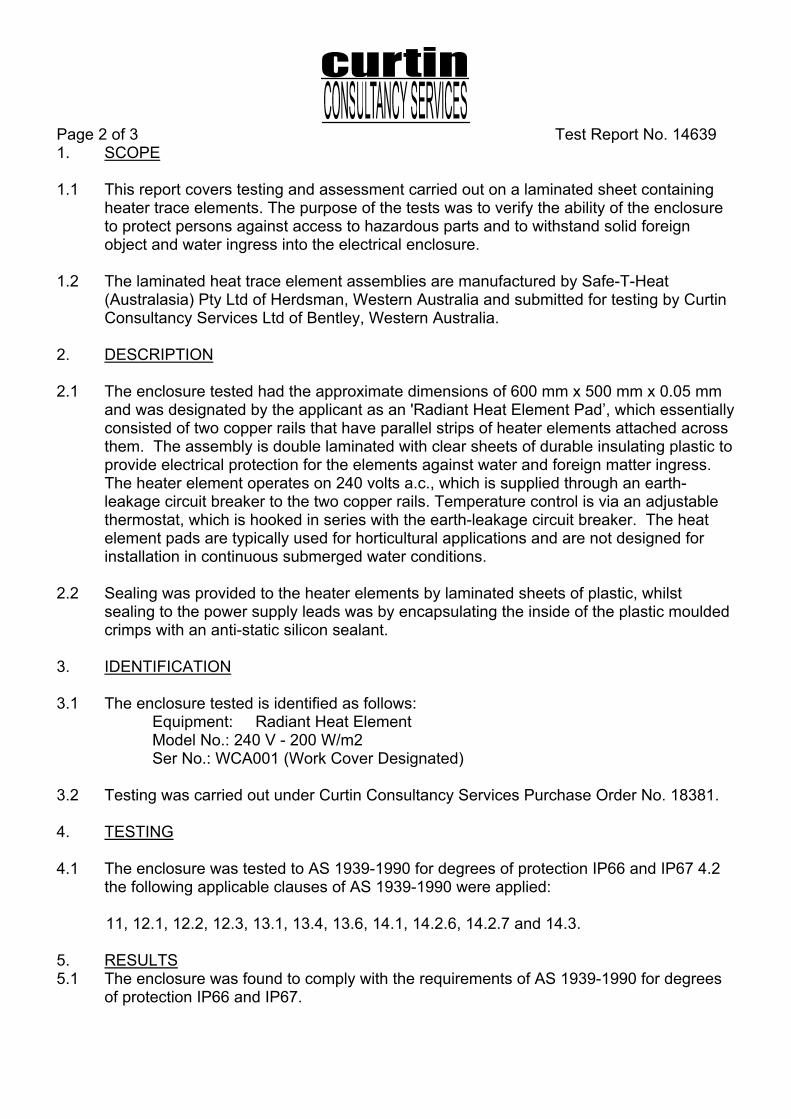
Page 2 of 3 Test Report No. 14639 1. SCOPE 1.1 This report covers testing and assessment carried out on a laminated sheet containing
heater trace elements. The purpose of the tests was to verify the ability of the enclosure to protect persons against access to hazardous parts and to withstand solid foreign object and water ingress into the electrical enclosure.
1.2 The laminated heat trace element assemblies are manufactured by Safe-T-Heat
(Australasia) Pty Ltd of Herdsman, Western Australia and submitted for testing by Curtin Consultancy Services Ltd of Bentley, Western Australia.
2. DESCRIPTION 2.1 The enclosure tested had the approximate dimensions of 600 mm x 500 mm x 0.05 mm
and was designated by the applicant as an 'Radiant Heat Element Pad’, which essentially consisted of two copper rails that have parallel strips of heater elements attached across them. The assembly is double laminated with clear sheets of durable insulating plastic to provide electrical protection for the elements against water and foreign matter ingress. The heater element operates on 240 volts a.c., which is supplied through an earth-leakage circuit breaker to the two copper rails. Temperature control is via an adjustable thermostat, which is hooked in series with the earth-leakage circuit breaker. The heat element pads are typically used for horticultural applications and are not designed for installation in continuous submerged water conditions.
2.2 Sealing was provided to the heater elements by laminated sheets of plastic, whilst
sealing to the power supply leads was by encapsulating the inside of the plastic moulded crimps with an anti-static silicon sealant.
3. IDENTIFICATION 3.1 The enclosure tested is identified as follows:
Equipment: Radiant Heat Element Model No.: 240 V - 200 W/m2 Ser No.: WCA001 (Work Cover Designated)
3.2 Testing was carried out under Curtin Consultancy Services Purchase Order No. 18381. 4. TESTING 4.1 The enclosure was tested to AS 1939-1990 for degrees of protection IP66 and IP67 4.2
the following applicable clauses of AS 1939-1990 were applied: 11, 12.1, 12.2, 12.3, 13.1, 13.4, 13.6, 14.1, 14.2.6, 14.2.7 and 14.3. 5. RESULTS 5.1 The enclosure was found to comply with the requirements of AS 1939-1990 for degrees
of protection IP66 and IP67.

Page 3 of 3 Test Report No. 14639 6. ADDITIONAL INFORMATION 6.1 The apparatus was tested as supplied and no other extemal influences, which may have
affected its IP rating, were taken into consideration, i.e., chemical or physical. 6.2 The apparatus was temporarily submerged in water to a depth of one meter (lm) for
duration of thirty minutes (30min). Whilst submerged, an insulation resistance test was conducted at 500V d.c. for one minute, with no breakdown of insulation observed.
6.3 Due to the nature of the apparatus construction, the dust ingress test was done by
assessment only. / 6.4 The heat element pad was not energized for the duration of the water tests. 6.5 Test Details
Test Date: 17th April 1996. Dust Test duration: Nil tests conducted due to nature of enclosure Water Test duration: 3 minutes with IPX6 nozzle.
30 minutes at a depth of one metre (IPX7) Work Cover Rep: P. Dowsing.
6.6 Test Equipment Details
EQUIPMENT SER No. CALIBRATION DUE
CALIBRATED BY
Vernier Caliper LC1457 28/06/96 Work Cover Tensiometer LC1485 12/09/96 Work Cover Stopwatch 492 20/06/96 Work Cover
BDM3 Megger 00713 06/06/96 Work Cover IPX6 Spray Nozzle 1180/2 05/07/99 Work Cover
P Dowsing. G.R. Sandlant. Technical Officer Senior Technical Officer (Electrical) (Electrical)

A.C.N. 008 751 175 GPO Box U 1987. Perth 6001 • Kent Street, Bentley 6102 • Western Australia Telephone (61 9) 351 3300 Internal 3300 Fax (61 9) 351 3290
REPORT ON
NEEDLE-FLAME TESTS ON ELECTRICAL HEATING FOILS
FOR
SAFE-T-HEAT
JULY, 1995

A.C.N. 008 751 175 GPO Box U 1987. Perth 6001 • Kent Street, Bentley 6102 • Western Australia Telephone (61 9) 351 3300 Internal 3300 Fax (61 9) 351 3290
DATE: 10 July 1995
REFERENCE: 1783
REPORT ON: NEEDLE-FLAME TESTS ON ELECTRICAL HEATING FOILS
FOR: SAFE-T-HEAT
PREPARED BY: ______________________________ Dr A ZURHAAR BAppSc GradDipChem(WAIT) MAppSc PhD (Curtin) MRACI CCHEM
Note to client: You may reproduce this report, for publicity for other purposes but only in full.

1. INTRODUCTION Following a request from Mr T Appleyard of Safe-T-Heat Radiant Heating Systems, Unit 1, 3 Natalie Way, Balcatta WA, ph. 240 1833, a series of needle flame tests, in accordance with AS 2420, were completed on a sample of ceiling heating radiant foil. The sample of foil product was presented for testing described as the "fire resistant" model. The needle-flame test is designed to assess the ignitability and flame propagation properties of materials when subjected to a flame resulting from a fault or overload condition within electrical equipment. The test is based on the application of a small butane flame to the test material so as to simulate the effect of flames resulting form fault conditions within the equipment. The test was conducted on sections of foil installed as recommended by Safe-T-Heat in a sandwich configuration between a Gyprock ceiling panel and a fibreglass insulation batt. The heating foil was powered on during testing. 2.0 FIRE RESISTANT MODEL The foil did not ignite upon contact with the flame over a period of 30 seconds. After 60 seconds contact time a small ignition flame could be achieved. In this event the foil continued to burn when the flame source was removed for only one second or less before it self extinguished. The damage to the foil was limited to an area of approximately 250ram2 and consisted primarily of distortion of shape and melting. The impact on surrounding insulation batts and ceiling panel was negligible and amounted to a minor discoloration of the surfaces. At no time was it possible to propagate a flame or produce an unassisted fire. 3.0 SUMMARY The "fire resistant" heating foil required prolonged contact with the flame before ignition could be achieved and even then the foil self extinguished after approximately one second. Damage to the foil and surrounding materials was minor and did not constitute a hazardous situation. In accordance with Section E9.1 of AS 2420, the following general statement must be noted; "These test results alone do not assess the fire hazard of the material or product made from this material under actual fire conditions. Consequently, the results of the test alone shall not be quoted in support of claims with respect to the fire hazard of the heating foil under actual fire conditions."

A,C.N. 008 751 175 GPO Box U 1987, Perth 6001 • Kent Street, Bentley 6102 • Western Australia Telephone (6 19) 351 3300 Internal 3300 Fax (6 19) 351 3290
REPORT ON
IGNITABILITY AND FLAME PROPAGATION PROPERTIES OF ELECTRICAL HEATING FOILS
(FIRE RESISTANT MODEL)
FOR
SAFE-T-HEAT
NOVEMBER, 1995

A.C.N. 008 751 175 GPO Box U 1957, Perth 6001 • Kent Street, Bentley 6102 • Western Australia Telephone (6 19) 351 3300 Internal 3300 Fax (6 19) 351 3290
DATE: November 1995 REFERENCE: 2005 REPORT ON: Ignitability And Flame Propagation Properties of Electrical Heating Foils (Fire Resistant Model) FOR: Safe-T-Heat PREPARED BY: ________________________ A ZURHAAR BAppSc GradDipChem(WAIT) MAppSc PhD(Curtin), MRACI CCHEM Note to client: You may reproduce this report, for publicity or other purposes, but only in full.

1.0 INTRODUCTION
Following a request from Mr B Appleyard of Safe-T-Heat Radiant Heating Systems, Unit 1, 3 Natalie
Way, Balcatta WA, ph. 240 1833, a series of tests were completed on samples of ceiling heating radiant
foil. The foil product presented for testing was described as the "fire resistant" model. The product was to
be tested for ignitability and flame propagation properties when exposed to accidental contact by an
oxyacetylene flame as may occur in real situations. Statistics show that the majority of roof and building
fires are due to mishaps occurring when tradesman are using oxyacetylene equipment in tight roof
spaces in the presence of combustible materials.
Several scenarios were simulated to cover all possible eventualities in a roof space that has had the
heating foil installed. Standard Gyprock ceiling panels were used in conjunction with a green
polyester/aluminum foil batt of density 750g/m3 and R-value of 2.5. The product code on the batt was
IFR25. The heating foil was installed in a sandwich configuration between the ceiling panel and the
insulation batt. The insulation batt was installed with the aluminum foil facing up away from the ceiling.
The heating foil is simply stapled. to the ceiling before the insulation batt is replaced on top. A one inch
overhang of foil was deliberately left exposed to provide every opportunity for a flame to become
established prior to spreading. The tests were completed both with the heating foil unit powered off and
with heating foil unit powered on. The test flame was produced by a standard oxy-acetylene set as used
by plumbers and tradesman. The gases were set for copper brazing. This is the most common
application for an oxy-acetylene flame within a roof space.
2.0 FIRE RESISTANT MODEL
The foil did not readily ignite upon contact with the flame and required continued contact before any
ignition could be achieved. In the event that the foil could be ignited, the foil continued to burn when the
flame source was removed for only one second or less before it self extinguished. At no time was it
possible to propagate a flame or produce an unassisted fire. Ignitability and flame propagation properties
were found to be independent of the heating foil's power status. These properties did not change when
the foil was powered on.
In an installation situation the exposed foil could not be made to burn unless it was in direct contact with
the flame. The sandwich nature of the installation set-up containing the insulation and ceiling panels
were not required to prevent flame propagation but as a matter of design, they provide an extra level of
protection against a fire. The particular type of polyester batt tested exhibited excellent fire resistance
properties. Under direct contact from the flame the polyester melts with no smoke or fumes being
emitted.
3.0 SUMMARY

The "fire resistant" heating foil model was found to live up to its name. It is fire resistant and could not
propagate a flame under all conditions tested. This model is clearly a superior product and can be
considered suitable for use in areas where accidental contact with flames would otherwise result in a
fire. The tests conducted were designed to simulate the results of a roof space accident, which is
recognized as a major cause of building fires in Australia. The tests have found that this type of foil used
in conjunction with the type of polyester batt tested affords a very high degree of fire resistance. No
evidence was found to suggest that the "fire resistant" heating foils nor the polyester insulation batts are
capable of initiating or contributing to a fire as a result of contact with an oxy-acetylene flame.

A.C.N. 008 751 175 GPO Box U 1957, Perth 6001 • Kent Street, Bentley 6102 • Western Australia Telephone (6 19) 351 3300 Internal 3300 Fax (6 19) 351 3290
REPORT ON
IGNITABILITY AND FLAME PROPAGATION PROPERTIES OF ELECTRICAL HEATING FOILS (STANDARD MODEL)
FOR
SAFE-T-HEAT
JANUARY, 1996

A.C.N. 008 751 175 GPO Box U 1957, Perth 6001 • Kent Street, Bentley 6102 • Western Australia Telephone (6 19) 351 3300 Internal 3300 Fax (6 19) 351 3290
DATE: 30 January 1996 REFERENCE: REPORT ON: Ignitability And Flame Propagation Properties of Electrical Heating Foils (Standard Model) used in conjunction with Town & Country Insulation Products FOR: Safe-T-Heat PREPARED BY: ________________________ Dr A ZURHAAR BAppSc GradDipChem(WAIT) MAppSc PhD(Curtin), MRACI CCHEM Note to client You may reproduce this report, for pubficity or other purposes, but only in full.

1.0 INTRODUCTION
Following a request from Mr B Appleyard of Safe-T-Heat Radiant Heating Systems, Unit 1, 3
Natalie Way, Balcatta WA, ph. 240 1833, a series of tests were completed on samples of ceiling
heating radiant foil installed in association with Town & Country Woolen Mills wool batts and
polyester batts. The foil product presented for testing was described as the "standard" model.
The product was to be tested for ignitability and flame propagation properties when exposed to
accidental contact by an oxy-acetylene flame as might occur in real situations. Statistics show
that the majority of roof and building fires are due to mishaps occurring when tradesmen are
using oxy-acetylene equipment in tight roof spaces in the presence of combustible materials.
Several scenarios were simulated to cover all possible eventualities in a roof space that has had
the heating foil installed. Two separate test situations were prepared. The first was based on
standard Gyprock ceiling panels used in conjunction with the off-white wool batt. The second
was based on standard Gyprock ceiling panels used in conjunction with the white polyester batt.
The heating foil was installed in a sandwich configuration between the ceiling panel and the
insulation batt. The heating foil is simply stapled to the ceiling before the insulation batt is
replaced on top. A one inch overhang of foil was deliberately left~ exposed to provide every
opportunity for a flame to become established prior to spreading. The tests were completed
both with the heating foil unit powered off and with the heating foil unit powered on. The test
flame was produced by a standard oxy-acetylene set as used by plumbers and tradesmen. The
gases were set for copper brazing. This is the most common application for an oxy-acetylene
flame within a roof space.

2.0 STANDARD MODEL
This foil type readily ignited upon contact with the flame and continued to burn when the flame
source was removed. The rate of flame propagation was approximately 10mm/sec and
increased with time. Ignitability was independent of the heating foil's power status. Rate of
burning did not change when the heating foil was powered on.
For the wool batt;
In an installation situation the exposed foil burned unassisted until the sandwich of insulation
and ceiling was reached. At this point, if the insulation batt was firmly placed against the ceiling
panel, the flame self-extinguished, most probably due to lack of air. When the insulation batt
was only loosely placed and/or there was an opportunity for a flame to come into direct contact
with the wool, the insulation burned profusely and emitted hazardous quantities of smoke and
fumes. A flame contact time of only one second was required for the wool to catch fire and
continue to burn unassisted until the fire had consumed all of the insulation available.
For the polyester batt;
In an installation situation the exposed foil burned unassisted until the sandwich of insulation
and ceiling was reached. At this point, if the insulation batt was firmly placed against the ceiling
panel, the flame self-extinguished, most probably due to lack of air and poor combustibility of
surrounding materials. When the insulation batt was only loosely placed the flame still self-
extinguished indicating that the polyester batt has assisted in smothering the flame and
preventing continued combustion. The polyester insulation batt did not burn but instead melted
in a safe and non-hazardous manner even after direct contact with the flame.

3.0 SUMMARY
In an installation situation free of insulation batts, the "standard" model of the heating foil was
found to act as a fire accelerant once ignited. When in contact with the wool insulation batt, the
heating foil was only found to extinguish when a lack of air appeared to be present. The wool
batt tested was clearly capable of propagating a fire and was found to be readily combustible.
This combination of standard heating foil and wool batt is not recommended as both materials
burn readily and will contribute to the spreading of a fire.
When in contact with the polyester insulation batt, the heating foil was found to self extinguish.
This termination of burning, however, is not due to the properties of the foil but instead is a
function of the nature and design of the other materials present. It is recommended that this
model only be used when installed in a sandwich design with a compatible insulation material.
The tests conducted have found that the fire hazards associated with the combustibility of the
foil can be substantially reduced when the Town & Country polyester batts are also installed.

A.C.N. 008 751 175 GPO Box U 1957, Perth 6001 • Kent Street, Bentley 6102 • Western Australia Telephone (6 19) 351 3300 Internal 3300 Fax (6 19) 351 3290
REPORT
on
SAFE-T-FLEX ROOM HEATING MATERIAL IN RELATION TO ELECTRO-MAGNETIC FIELD
EXPOSURE LIMITS
for
SAFE-T-HEAT

A.C.N. 008 751 175 GPO Box U 1957, Perth 6001 • Kent Street, Bentley 6102 • Western Australia Telephone (6 19) 351 3300 Internal 3300 Fax (6 19) 351 3290
DATE: 08 NOVEMBER 1993 REFERENCE: 819 REPORT ON: SAFE-T-FLEX ROOM HEATING MATERIAL IN RELATION TO ELECTRO - MAGNETIC FIELD EXPOSURE LIMITS FOR: SAFE-T-HEAT PREPARED BY: __________________________ M SCHNEIDERHEINZE Ingenieur (Berlin) Diplom-Ingenieur (Berlin) Lecturer School of Electrical & Computer Engineering Curtin University of Technology Note to client: You may reproduce this report, for publicity or other purposes, but only in full. 0819.doc

1.0 EXECUTIVE SUMMARY A product named Safe-t-Flex was investigated in regard to electric and magnetic fields generated during operation. Two cases were assumed. First, a worst case was considered, in which humans are in direct contact with the product. Secondly, the relaxed condition, in which human beings are situated at some distance from the product, as is the case when the product is installed on room ceilings, was applied. The quantities obtained were related to the limits for exposure of human beings to electric and magnetic fields. The most stringent exposure limits (exposure of general public) were used as reference. It was found, that the strength of both the electric and the magnetic field generated by the product Safe-t-Heat, is, even in worst-case conditions, is significantly below the most stringent exposure limits as set out by the National Health and Medical Research Council, and the International Radiation Protection Association (IRPA/INIRC).

2.0 THE PRODUCT IN RELATION TO ELECTROMAGNETISM 2.1 Nature of Safe-t-Flex The product investigated for its electric and magnetic fields appears under the brand name Safe-t-Flex. The original purpose of Safe-t-Flex is to convert electrical energy into heat energy, and radiate the heat from its planar sides into a room, for the comfort of people living in them. The product comes as a broad, ca. 0.3 m wide, plastic film, at a variable length of up to 6m, and the intention is to have it attached to the ceiling of a room. In that way, the source of heat radiation is not concentrated on a small area, as is common when using room heaters, but may extend over the whole ceiling area. This leads to certain advantages, which are discussed in the manufacturer's brochures. Safe-t-Flex consists of heating elements made from a thin electrically resistive film, sandwiched between two layers of resilient plastic film, used as carders and electrical insulators. The heating elements are laid out as strips of resistive film, perpendicularly to the direction of the Safe-t-Flex band. Electrically, the ends of the resistive strips are connected to two common strips, forming the rails through which the resistive strips are connected to mains power. 2.2 Electric and Magnetic Fields Wherever there exists an electrical charge, there is an associated electric field; and wherever there is an electric current flow, there exists an associated magnetic field. To assess the radiation risk of an electro technical product such as Safe-t-Flex, it is, therefore, necessary to identify the magnitudes of both electric and magnetic field components, compare them with the currently valid regulations, and discuss the relevance of the findings. 2.3 Coupling Mechanisms and Impact on Human Bodies Electric potential and electric current flow is inextricably related with electric and magnetic fields. These fields surround the electrical conductors; their strengths decrease with distance. Objects placed in the space surrounding the conductors will interact with the respective fields, in a more or less pronounced way. 0819.doc

The operating frequency of 50 hertz is very low, and the mechanism of power transfer into human bodies is constrained to the induction of electric currents (as opposed to wave transmission). That is to say, the electromagnetic field induces electric currents in objects placed near the electric conductor. The amount of induced current depends on conductivity, permitivity, and permeability of the object. For example, if the object is metallic, these quantifies were comparably large, and the induced current significant. If the object is human tissue, these quantities differ little from those of the surrounding space, and consequently, only small currents are being induced. The principal effects on human organisms are due to interactions with excitable membranes of nerve and muscle cells, and they depend on the current density induced in the body. Electric currents are intrinsic part of the functioning of human organisms. Indeed, current densities of 10 mA/m2 are of the order of magnitude of spontaneous endogenous current densities. 2.4 Exposure Limits In establishing guidelines for limits of electromagnetic fields, the respective committees followed the rationale, that current densities, induced in human bodies by human-made technology, should not exceed the order of magnitude of their inherent current densities. Additional attention was also given to long-term effects associated with the exposure. Currently valid limits: The current limits are set out in the "Interim Guidelines-on Limits of Exposure to 50/60 Hz Electric and Magnetic Fields (1989)" of the National Health and Medical Research Council, Approved at the 108th session of the National Health and Medical Research Council, Canberra, November 1989. The National Health and Medical Research Council has basically followed international practice, and ensured the conformity of the limits with those developed by the International Non-Ionizing Radiation Committee of the International Radiation Protection Association. (IRPA/INIRC). 0819.doc

There are two categories of exposure limits: Occupational, and General Public. The General Public category is more stringent, and has been used as a reference for this test. Electric Field Limits, General Public: Members of the general public should not be exposed on a continuous basis to unperturbed rms electric field strengths exceeding 5 kV/m. This restriction applies to open spaces in which members of the general public might reasonably be expected to spend a substantial part of the day, such as recreational areas, meeting grounds, and the like. Exposure to fields between 5 and 10 kV/m should be limited to a few hours per day. When necessary, exposures to fields in excess of lO kV/m can be allowed for a few minutes per day, provided the induced current density does not exceed 2 mA/m2 and precautions are taken to prevent hazardous indirect coupling effects. It should be noted that buildings in a 5 kV/m external field have field strength lower by more than an order of magnitude inside the building. Magnetic field limits, General Public: Members of the general public should not be exposed on a continuous basis to unperturbed rms magnetic flux densities exceeding O. 1 mT. This restriction applies to open spaces in which members of the general public might reasonably be expected to spend a substantial part of the day. Exposures to magnetic flux densities between O. 1 and 1.0 mT (rms) should be limited to a few hours per day. When necessary, exposures to magnetic flux densities in excess of l mT should be limited to a few minutes per day. 0819.doc

3.0 ELECTRIC AND MAGNETIC FIELDS GENERATED BY SAFE-T-FLEX 3.1 Electric Field Electrically, the Safe-t-heat product presents chiefly ohmic impedance to the voltage supply of 240 V rms, at 50 Hz. Its inductive and capacitive components are negligible. It follows, that the maximum electric potential anywhere in the product is 240 V rms. The maximum electric field strength generated in the product can be derived from the maximum electric potential difference between the respective conductors in closed proximity of one another. This condition is met by the outermost conductors, which can be considered the supply rails for the various heating elements that interconnect these conductors. Their distance is 0.27 m. The field strength, directed from one conductor to the other, is E = V/d = 240Vrms/0.27m = 880V/m E = 0.88 kV/m This is the "worst case" field strength, to which a human body would be exposed when in direct contact with the product. As the product will generally be found attached to room ceilings, the u[~perturbed filed strength in the lower section of a room where humans are usually found, will be at least one order of magnitude smaller. In regard to the field strength of the product with respect to earth, the product can be considered in the same way as ordinary building wiring is, with its negligible resultant field strengths. Versions of Safe-t-Flex wider than 0.27 m generate even smaller field strengths. It can be seen, that the unperturbed electric field strength generated by Safe-t-Flex, assuming the worst case of direct contact, is 0.88 kV/m. This is significantly below the limit of 5 kV/m for continuous exposure. As persons will be found at some distance from the product, their exposure will be significantly below the worst case Value. It may be inferred, that the electric field strength generated by Safe-t-Flex is significantly below the limit as set out by the National Health and Medical Research Council. 0819.doc
3.2 Magnetic Field As the area of relevance is situated within the induction field of the product's electric conductors, the magnetic field components cannot be directly calculated from the electric field components. For that reason, the magnetic field was measured directly. The instrument used was a self-calibrated magnetic field strength meter (Bell 610 Gauss meter). As magnetic fields increase with current, a worst-case maximum current flow of 10 A was caused by additionally loading the supply rail ends opposite to the contact terminals with a variable resistor. The maximum magnetic flux density measured at closest possible proximity to the supply rails was less than 0.01 mT rms. This value is more than one order of magnitude below the limit of 0.1 mT rms. At distances greater than 0.1 m from any point of the product, the magnetic flux density was not measurable. As persons will be found at some distance from the product, their exposure will be significantly below the worst case value. It may be inferred, that the magnetic flux density generated by Safe-t-Flex is significantly below the limit as set out by the National Health and Medical Research Council. .-,r 4.0 CONCLUSIONS Both electric and magnetic field strength, generated by operating the product Safe-t-Flex are, even under worst case conditions, significantly below the limits as set out by the National Health and Medical Research Council, and the International Radiation Protection Association (IRPA/INIRC). 0819.doc