Embed Size (px)
Citation preview

DataTree 3D 1080p UV User’s Guide
1 OVERVIEW 32 ENGINE INTRODUCTION 33 ENGINE SPEC 44 IMAGE SIZE SPEC AND MASK 55 OPERATION PROCEDURE 66 PROJECTION LENS FOCUS ADJUSTMENT 207 THERMAL SUGGESTION 218 PACKING 219 TROUBLE SHOOTING 2210 APPENDIX: SPI READ MASK FILE SAMPLE CODE 22
Table of Contents

3
DataTree 3D 1080p UV User’s Guide
1 Overview This user’s guide presents an overview of the J3D 1080p UV Engine and ageneral description of the main features and functions. It explains the first stepsfor the user to get started.
2 Engine Introduction The J3D 1080p UV Engine is configured and based on a UV LED and Texas Instruments’ DMD. All glass lenses and optical coatings are optimized for 405nm wavelength light. Besides, 0% offset optical archi-tecture is designed for getting smaller distortion.
Note: The operation temperature is 5~35 0C
Figure 1. J3D 1080p UV Engine Dimension 234mm x 103mm x 126mm

4
DataTree 3D 1080p UV User’s Guide
3 Engine Spec 3.1 J3D 1080p UV Engine Performance is based on below Standard Test Conditions:
Warm-Up Period 3 minutes LED Duty Cycle 100% LED Current 5A LED Junction Temperature System side need provide the cooling module to make
Tj below 90 0C Ambient Light 0mW @405nm (Dark Room) Ambient Temperature 25oC Input Signal 1920 x 1080 Pattern @60Hz
3.2 Engine Performance:
Parameter Typical Value Unit UV Output Power 400 mW FO:FO Contrast Ratio 1000:1 TV Distortion 1 %
Note 1: TV Distortion Definitions:Horizontal: (W1+W3-2*W2) / 2*W2Vertical: (V1+V3-2*V2) / (2*V2)
Note: Component and Engine module are both RoHS compliant.

5
DataTree 3D 1080p UV User’s Guide
4 Image Size Spec and Mask 4.1 Image size spec::
J3D 1080p UV Engine supports three image sizes as the following table.
Note: When changing the image size, focus adjustment is required.(Please refer to ‘’6. Projection Lens Focus Adjustment’’ Section)
Image Size 2.2 inch 4.3 inch 8.7 inch UNITImage Pixel Size 25 50 100 umImage Resolution 1016 508 254 ppiImage Width 48 96 192 mmImage Height 27 54 108 mmProjection Distance 77.6 174.1 368.8 mm

6
DataTree 3D 1080p UV User’s Guide
4.2 Definition of Mask Optic measurement point
5 Operation Procedure 5.1 Part Check List Part Qty Picture AssemblyLight Engine 1
Transfer Board 1

7
DataTree 3D 1080p UV User’s Guide
5.2 Transfer Board I/F introduction
- Power Connector: For 12V/ 4A DC adaptor input (Ø 2.1mm type )- 12V input: Location J47 for 12V power input: (See 5.2.1 for details)- Mini USB connector: Connect to computer for Light Engine Control- HDMI Connector: For 1080p (1920x1080 / 60Hz) video resolution input source- I2C connector: Location J50 for I2C communication function (See 5.2.1 for details)- Signal Connector: Location J46 for control signals in/out (See 5.2.1 for details)
5.2.1 Connector Information
Location Pin Number Function P/N VendorJ47 8 12V INPUT TU1502WNV-08S TARNG YUJ50 4 12C I/F TU1502WNV-04S TARNG YUJ46 6 SINGAL INPUT TU1502WNV-06S TARNG YU
8
DataTree 3D 1080p UV User’s Guide
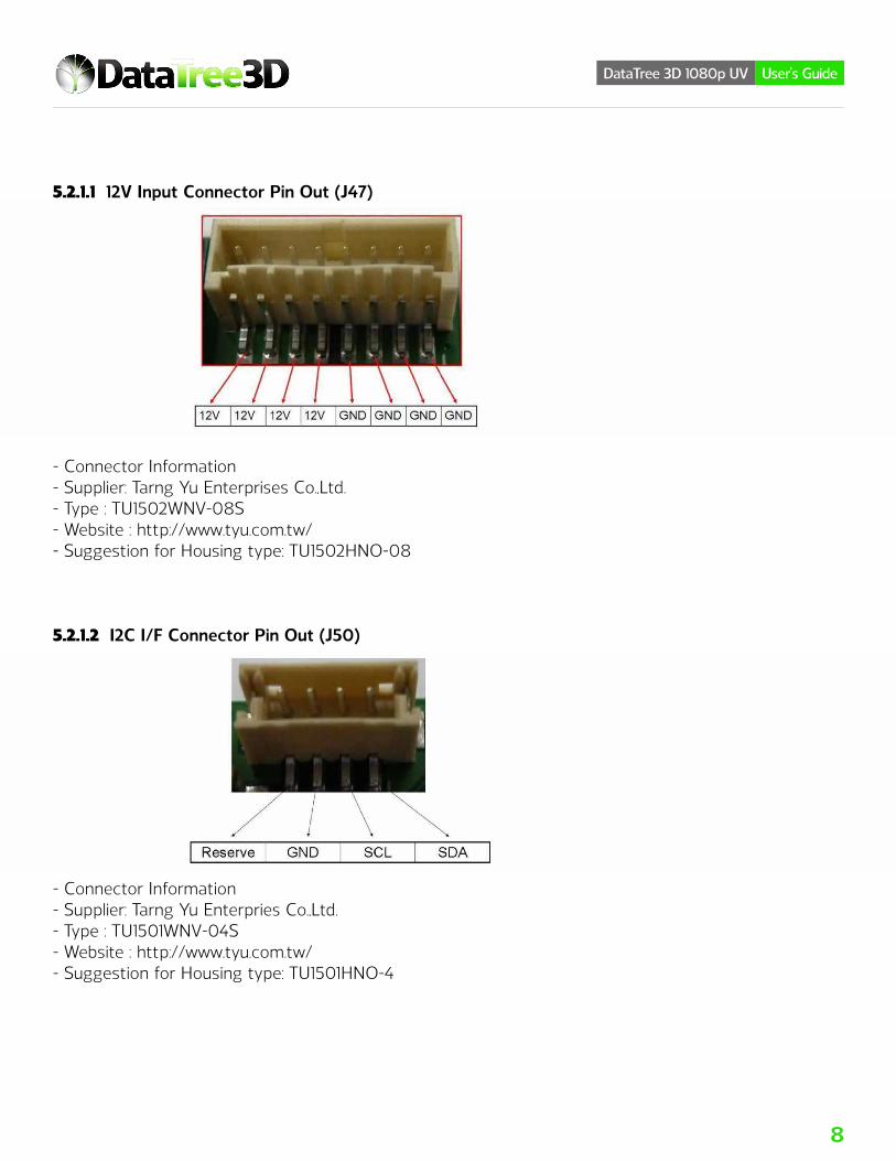
5.2.1.1 12V Input Connector Pin Out (J47)
- Connector Information- Supplier: Tarng Yu Enterprises Co.,Ltd.- Type : TU1502WNV-08S- Website : http://www.tyu.com.tw/- Suggestion for Housing type: TU1502HNO-08
5.2.1.2 I2C I/F Connector Pin Out (J50)
- Connector Information- Supplier: Tarng Yu Enterpries Co.,Ltd.- Type : TU1501WNV-04S- Website : http://www.tyu.com.tw/- Suggestion for Housing type: TU1501HNO-4

9
DataTree 3D 1080p UV User’s Guide
5.2.1.3 Signal Input Connector Pin Out (J46)
- Connector Information- Supplier: Tarng Yu Enterpries Co.,Ltd.- Type : TU1501WNV-06S- Website : http://www.tyu.com.tw/- Suggestion for Housing type: TU1501HNO-6
Note:- Please install the USB driver on the computer first if you need to access mini USB connector.- USB driver download website: http://www.cypress.com/documentation/software-and-drivers/usb-serialsoftware-development-kit- File name: CypressDriverInstaller.exe- Power input option: Either Location J52 or Location J47- Light Engine control option: Either Location J56 Mini USB connector or Location J50 I2C Interface.- PROJ_ON control option: Location JP1(Jumper short), Location J46 or by USB- I/F control

10
DataTree 3D 1080p UV User’s Guide
5.3 Signal Timing and Level List Signal Timing
Note:1) Please follow power up and power down sequence to avoid DMD damage.2) Upon completion of Auto-Init, the M_HOST_IRQ / S_HOST_IRQ will be set to a logic Low state
to indicate the completion of Auto-Init. In the Auto-Init meantime, I2C access to ASIC should not start until M_HOST_IRQ / S_HOST_IRQ goes low.
PIN NAME VOLTAGE LEVELPROJ_ON 3.3V
SCL 3.3VSDA 3.3V
LED ON / OFF 3.3VM_HOST_IRQ 3.3VQ_HOST_IRQ 3.3V
SIGNAL LEVEL TEST
11
DataTree 3D 1080p UV User’s Guide
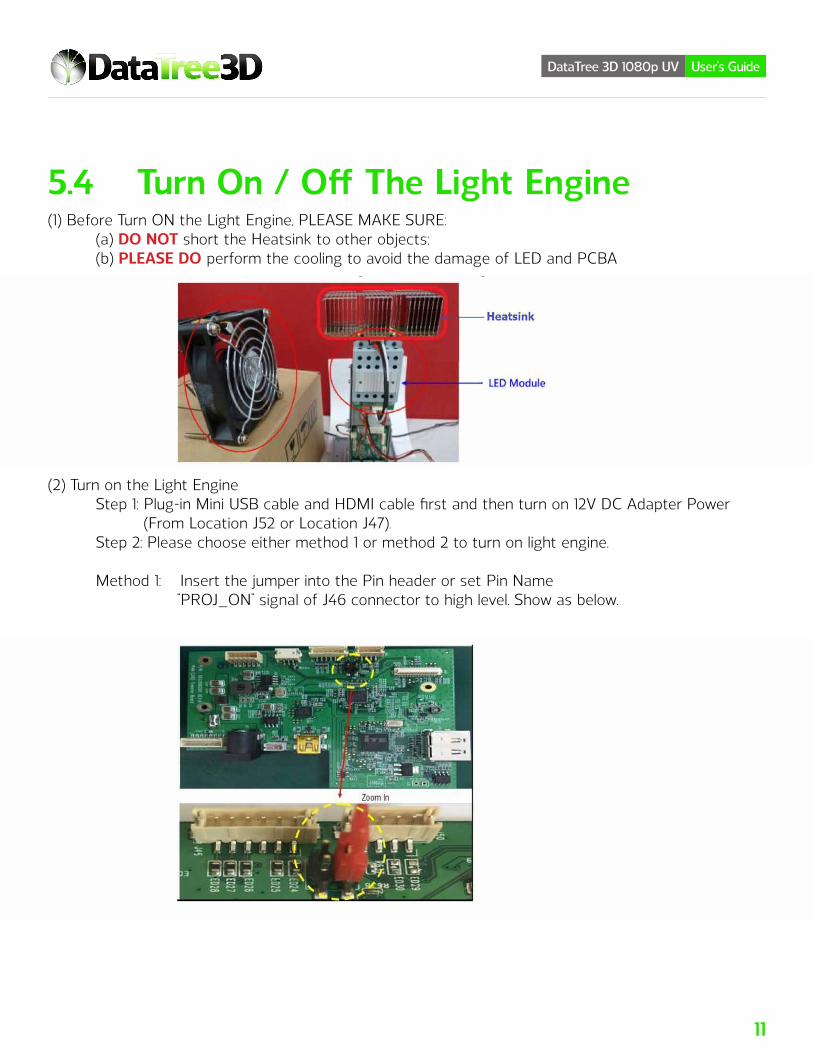
5.4 Turn On / Off The Light Engine(1) Before Turn ON the Light Engine, PLEASE MAKE SURE: (a) DO NOT short the Heatsink to other objects; (b) PLEASE DO perform the cooling to avoid the damage of LED and PCBA
(2) Turn on the Light Engine Step 1: Plug-in Mini USB cable and HDMI cable first and then turn on 12V DC Adapter Power (From Location J52 or Location J47). Step 2: Please choose either method 1 or method 2 to turn on light engine.
Method 1: Insert the jumper into the Pin header or set Pin Name “PROJ_ON” signal of J46 connector to high level. Show as below.
12
DataTree 3D 1080p UV User’s Guide
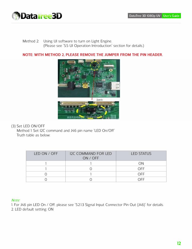
Method 2: Using UI software to turn on Light Engine. (Please see “5.5 UI Operation Introduction’’ section for details.)
NOTE: WITH METHOD 2, PLEASE REMOVE THE JUMPER FROM THE PIN HEADER.
(3) Set LED ON/OFF Method 1: Set I2C command and J46 pin name “LED On/Off” Truth table as below:
Note:1. For J46 pin LED On / Off, please see “5.2.1.3 Signal Input Connector Pin Out (J46)” for details.2. LED default setting: ON
LED ON / OFF I2C COMMAND FOR LED ON / OFF
LED STATUS
1 1 ON1 0 OFF0 1 OFF0 0 OFF

13
DataTree 3D 1080p UV User’s Guide
Method 2: Set LED current. (Please refer to “5.6 User I2C Command set” for details).
(4) Turn off the Light EngineStep1: Please choose either method 1 or method 2 to turn off light engine. Method 1: Remove Location JP1 Jumper from the Pin header or set Pin Name “PROJ_ON” signal of J46 connector to low level.
Method 2: Use UI software to turn off light engine. (Please see “5.5 UI Operation Introduction’’ section for details)
Step2: Turn off 12V DC Adapter Power (Location J52 or Location J47).
Note: Please follow power up and power down sequence accordingly; wrong operations will cause the damage of DMD.
5.5 UI Operation Introduction
14
DataTree 3D 1080p UV User’s Guide
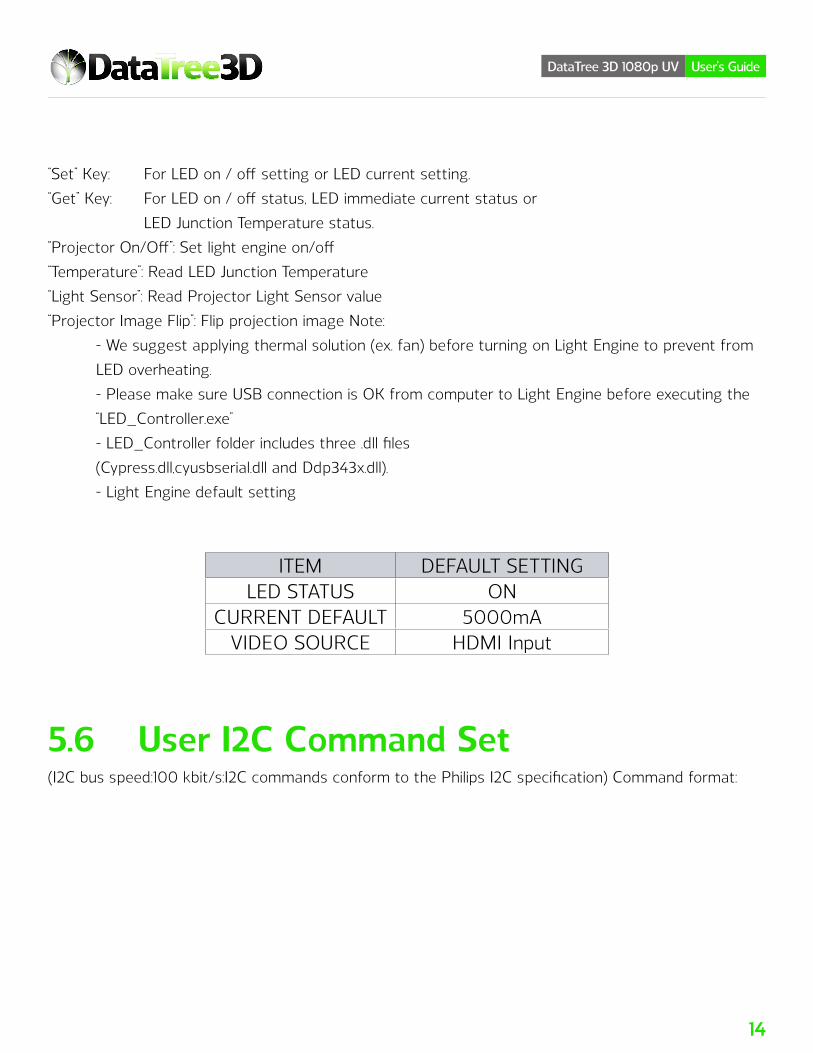
“Set” Key: For LED on / off setting or LED current setting.“Get” Key: For LED on / off status, LED immediate current status or LED Junction Temperature status.“Projector On/Off”: Set light engine on/off“Temperature”: Read LED Junction Temperature“Light Sensor”: Read Projector Light Sensor value“Projector Image Flip”: Flip projection image Note: - We suggest applying thermal solution (ex. fan) before turning on Light Engine to prevent from
LED overheating. - Please make sure USB connection is OK from computer to Light Engine before executing the
“LED_Controller.exe” - LED_Controller folder includes three .dll files (Cypress.dll,cyusbserial.dll and Ddp343x.dll). - Light Engine default setting
5.6 User I2C Command Set(I2C bus speed:100 kbit/s:I2C commands conform to the Philips I2C specification) Command format:
ITEM DEFAULT SETTINGLED STATUS ON
CURRENT DEFAULT 5000mAVIDEO SOURCE HDMI Input
15
DataTree 3D 1080p UV User’s Guide
Slave device address:0x1B [0x37 (Read) / 0x36 (Write)] 1st Byte = Command 2nd Byte = Data [0] 3rd Byte = Data [1]LED Current Setting Command: 0x54 Data [0] Reserved ( set to 0x00) Data [1] Reserved ( set to 0x00) Data [2] LED current parameter (LSByte) Data [3] LED current parameter (MSByte) Data [4] Reserved ( set to 0x00) Data [5] Reserved ( set to 0x00)LED Current Formula=[(Bit value+1)/1024] x 6 For Bit value=1 to 1023The step of current setting is 5.8593mA.\Example as below:If the UV LED current is 5000mA then the setting value is 0x354(5000/5.8651= 853 = 0x355). Command: 0x54 // Write LED current Data[0] = 0x00 // Data[1] = 0x00 // Data[2] = 0x54 // LED current parameter (LSB) Data[3] = 0x03 // LED current parameter (MSB) Data[4] = 0x00 // Data[5] = 0x00 //LED Enable / DisableCommand : 0x52 // Write LED Enable / Disable Data[0] = 0x02 // LED enabled Command : 0x52 // Write LED Enable / Disable Data[0] = 0x00 // LED disabled
Note: Please make sure the video signal input, otherwise the LED will be turnoff automatically.

16
DataTree 3D 1080p UV User’s Guide
Read LED Junction Temperature Step 1: write command Command: 0xD6 Step 2: read data Data [0] LED Junction Temperature (LSByte) Data [1] LED Junction Temperature (MSByte)LED Junction Temperature need to be calculated according to LED On/Off and current status If LED is on: LED_Junction_Temp = (Data[1]*256 + Data[0])/10 + DW*Vol*LED_I/1000 Else if LED is off: LED_Junction_Temp = (Data[1]*256 + Data[0])/10 Note: - DW is the LED thermal resister is 1.6 (°C/W) - Vol is the LED operating voltage is about 4V - LED_I is the LED current (mA)Projector Image Flip Setting Command : 0x14 // Write Projector Image Flip Setting Data[0] = 0x00 // No Flip Command : 0x14 // Write Projector Image Flip Setting Data[0] = 0x02 // Horizontal Flip Command : 0x14 // Write Projector Image Flip Setting Data[0] = 0x04 // Vertical Flip Command : 0x14 // Write Projector Image Flip Setting Data[0] = 0x06 // Horiontal and Veritcal FlipRead Light Sensor Value Command formatSlave device address: 0x39 [0x73 (Read)] 1st Byte = Command 2nd Byte = Data [0] 3rd Byte = Data [1]

17
DataTree 3D 1080p UV User’s Guide
Step 1: write command Command: 0xACStep 2: read data Data [0] Light sensor value (LSByte) Data [1] Light sensor value (MSByte) Light_Sensor = (Data[1]*256 + Data[0])
Note: Suggest to read the light sensor value with a fixed pattern. Lightsensor value may differ with different patterns.
5.7 Pixel Data Mixed With Mask File And Read Mask File From SPI Flash
5.7.1 Prerequisite - The mask file is a 8-bit PNG file, with the resolution of 1920*1080, and each pixel data would be
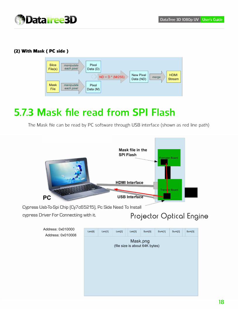
a value of 0~255. - The mask file must be pre-mixed with each slice file in advance, on the PC side, and pix-
el-by-pixel. - The mixed method is (New Pixel Data) = (Original Pixel Data) * ((Mask Data) / 255)
5.7.2 Prerequisite (1) Without Mask ( PC side )
18
DataTree 3D 1080p UV User’s Guide
(2) With Mask ( PC side )
5.7.3 Mask file read from SPI Flash The Mask file can be read by PC software through USB interface (shown as red line path)

19
DataTree 3D 1080p UV User’s Guide
Address: 0x010000~0x010003The length of mask fileAddress: 0x010004~0x010007The check sum of mask fileAddress: 0x010008~The mask file (file size is about 64K bytes)
5.7.5 Read Mask file steps
Note: Please see “10. Appendix: SPI Read Mask file Sample Code” for reference.

20
DataTree 3D 1080p UV User’s Guide
6 Projection Lens Focus Adjustment Step1: Loose the 2 screws (1, 2) to adjust the focus Step2: Roll the Focus Ring (3) to adjust the focus Step3: Fix the 2 screws (1, 2) after the focus adjusted

21
DataTree 3D 1080p UV User’s Guide
7 Thermal Suggestion
8 Packing8.1 Antistatic package

22
DataTree 3D 1080p UV User’s Guide
9 Trouble Shooting (1) If the light engine can not be turn on or no image projected, please turn off the light engine.
Then, check the cable connections and turn it on again. (2) If you can not control the light engine via the software, please re-connect the USB cable or
check if the software is installed correctly.
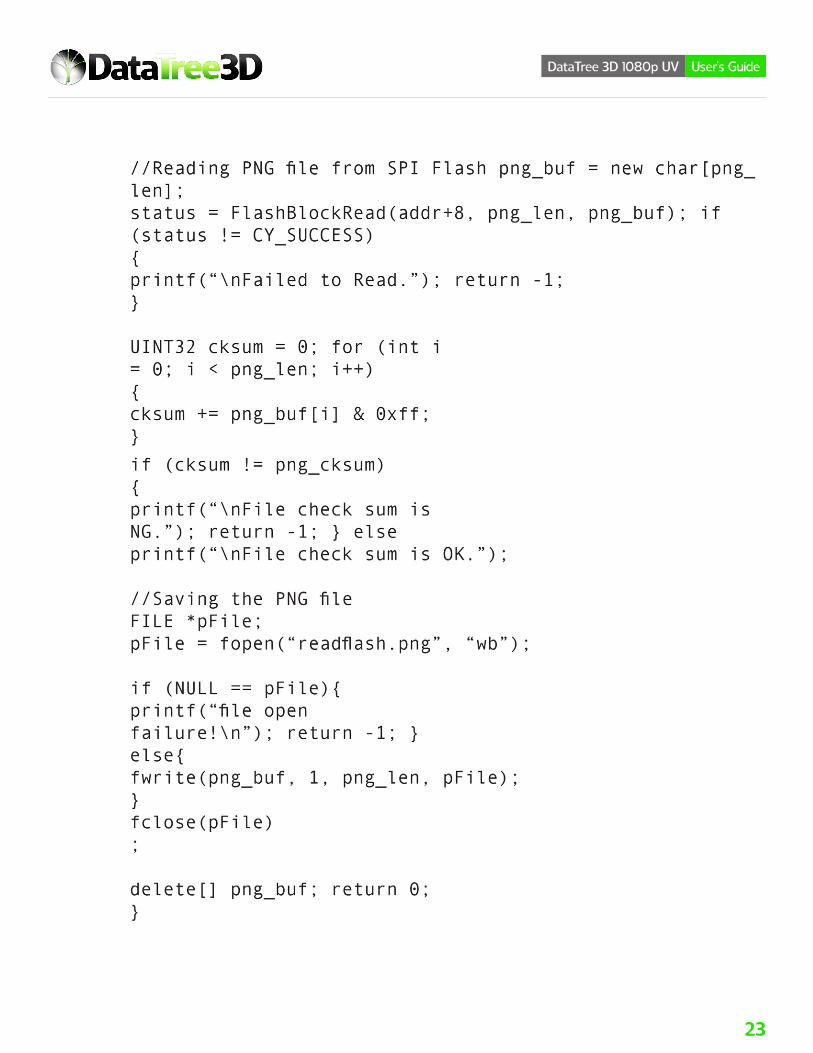
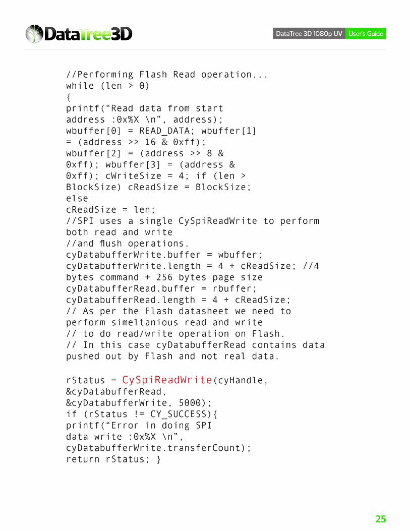
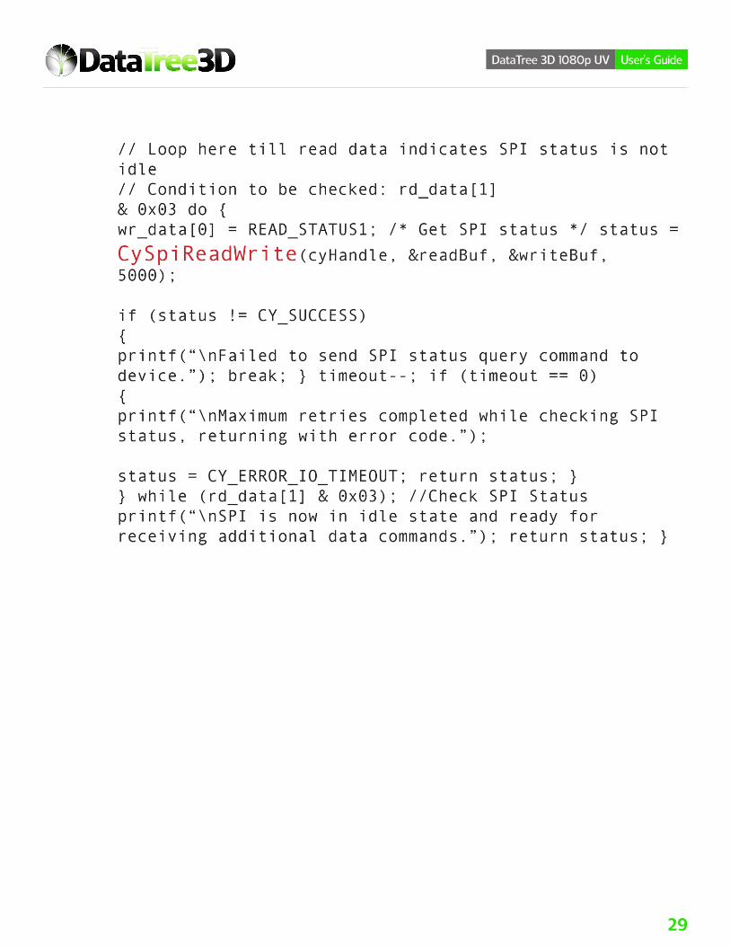
10 Appendix: SPI Read Mask File Sample Code
23
DataTree 3D 1080p UV User’s Guide

24
DataTree 3D 1080p UV User’s Guide
25
DataTree 3D 1080p UV User’s Guide

26
DataTree 3D 1080p UV User’s Guide

27
DataTree 3D 1080p UV User’s Guide

28
DataTree 3D 1080p UV User’s Guide
29
DataTree 3D 1080p UV User’s Guide