Embed Size (px)
Citation preview
Datasheet
Universal Monitoring Module
Document 1077787 Rev. F (Oct. 2013)
Overview
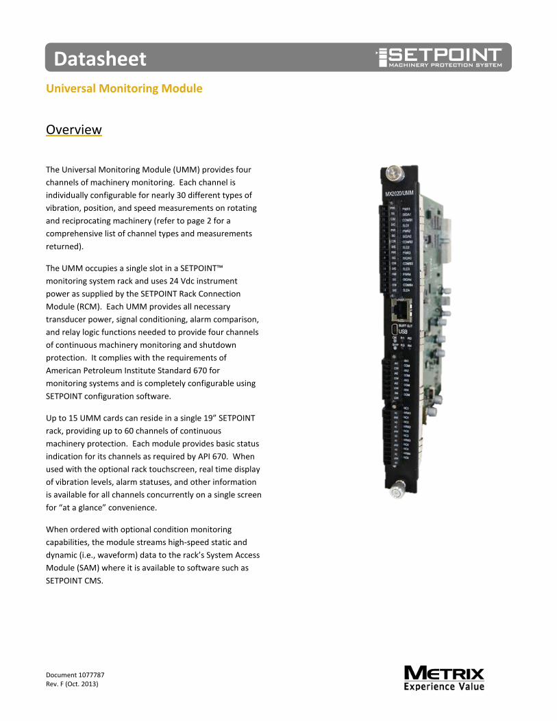
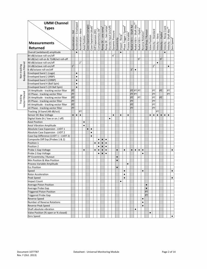
The Universal Monitoring Module (UMM) provides four channels of machinery monitoring. Each channel is individually configurable for nearly 30 different types of vibration, position, and speed measurements on rotating and reciprocating machinery (refer to page 2 for a comprehensive list of channel types and measurements returned).
The UMM occupies a single slot in a SETPOINT™ monitoring system rack and uses 24 Vdc instrument power as supplied by the SETPOINT Rack Connection Module (RCM). Each UMM provides all necessary transducer power, signal conditioning, alarm comparison, and relay logic functions needed to provide four channels of continuous machinery monitoring and shutdown protection. It complies with the requirements of American Petroleum Institute Standard 670 for monitoring systems and is completely configurable using SETPOINT configuration software.
Up to 15 UMM cards can reside in a single 19” SETPOINT rack, providing up to 60 channels of continuous machinery protection. Each module provides basic status indication for its channels as required by API 670. When used with the optional rack touchscreen, real time display of vibration levels, alarm statuses, and other information is available for all channels concurrently on a single screen for “at a glance” convenience.
When ordered with optional condition monitoring capabilities, the module streams high-speed static and dynamic (i.e., waveform) data to the rack’s System Access Module (SAM) where it is available to software such as SETPOINT CMS.
Document 1077787 Datasheet - Universal Monitoring Module Page 2 of 14 Rev. F (Oct. 2013)
UMM Channel Types Measurements Returned Ac
cele
ratio
n –
Std
Acce
lera
tion
– En
velo
ped
Acce
lera
tion
– Ae
ro
Axia
l Pos
ition
Ca
se E
xpan
sion
(sin
gle)
Ca
se E
xpan
sion
(dua
l)2 Di
ff Ex
pans
ion
(DE)
Co
mpl
emen
tary
DE1
Ram
p DE
– o
ne ra
mp2
Ram
p DE
– tw
o ra
mps
2 Di
scre
te In
put (
on/o
ff)
Dyna
mic
Pre
ssur
e Ec
cent
ricity
Im
pact
- Re
cip3
Phas
e Tr
igge
r / S
peed
4 Pr
oces
s Var
iabl
e5 Ra
dial
Vib
’n –
Sha
ft Re
l Ra
dial
Vib
’n -
Shaf
t Abs
2,6
Radi
al V
ib’n
– H
ydro
7 Re
vers
e Ro
tatio
n2 Ro
d Dr
op /
Runo
ut
Valv
e Po
sitio
n Ve
loci
ty –
Sta
ndar
d Ve
loci
ty –
Aer
o Ve
loci
ty –
Hyd
ro7
Velo
city
– R
ecip
Cra
nk
Velo
city
- Sh
aft A
bs2,
6 Ze
ro S
peed
2
Overall (wideband) amplitude ● ●
●
Non
-tra
ckin
g
Band
pass
Filt
ered
84 dB/octave roll-on/off 41 84 dB/oct roll-on & 72dB/oct roll-off 91 91 48 dB/octave roll-on/off 21 ● 24 dB/octave roll-on/off 21 21 ● 6 dB/octave roll-on/off 31 ● Enveloped band 1 (cage) ● Enveloped band 2 (IRBP) ● Enveloped band 3 (ORBP) ● Enveloped band 4 (Ball Spin) ● Enveloped band 5 (2X Ball Spin) ●
Trac
king
Ve
ctor
Filt
ered
1X Amplitude - tracking vector filter PT PT PT PT PT PT PT 1X Phase - tracking vector filter PT PT PT PT PT 2X Amplitude - tracking vector filter PT PT PT PT PT 2X Phase - tracking vector filter PT PT PT nX Amplitude - tracking vector filter PT PT PT nX Phase - tracking vector filter PT PT PT
Tracking 1X band (48 dB/oct) PT PT
Sensor DC Bias Voltage ● ● ● ● ● ● ● ● ● ● ● ●
Digital State (hi / low or on / off) ●
Axial Position ●
Axial Vibration Amplitude ●
Absolute Case Expansion - LVDT 1 ● ●
Absolute Case Expansion - LVDT 2 ●
Case Exp Difference (LVDT 1 – LVDT 2) ●
Composite Diff Exp (Probes 1 & 2) ● ● ●
Position 1 ● ● ● ●
Position 2 ● ● ●
Probe 1 Gap Voltage ● ● ● ● ● ● ● ● ● ● ● ●
Probe 2 Gap Voltage ● ● ● ●
PP Eccentricity / Runout ●
Min Position & Max Position ●
Process Variable Amplitude ●
Ecc Position ●
Speed ● ● ●
Rotor Acceleration ●
Peak Speed ● ●
Impact Count ●
Average Piston Position ●
Average Probe Gap ●
Triggered Piston Position PT
Triggered Probe Gap PT
Reverse Speed ●
Number of Reverse Rotations ●
Reverse Peak Speed ●
Shaft absolute vibration ●
Valve Position (% open or % closed) ●
Zero Speed ●
Document 1077787 Datasheet - Universal Monitoring Module Page 3 of 14 Rev. F (Oct. 2013)
NOTES:
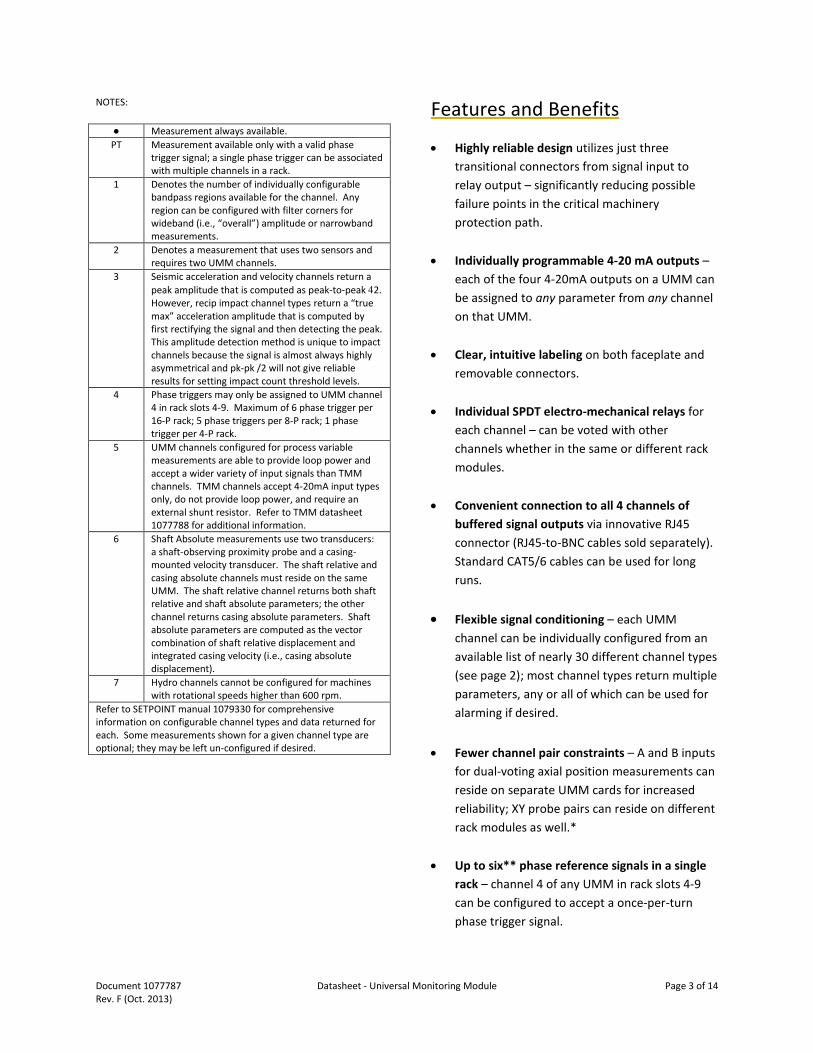
● Measurement always available. PT Measurement available only with a valid phase
trigger signal; a single phase trigger can be associated with multiple channels in a rack.
1 Denotes the number of individually configurable bandpass regions available for the channel. Any region can be configured with filter corners for wideband (i.e., “overall”) amplitude or narrowband measurements.
2 Denotes a measurement that uses two sensors and requires two UMM channels.
3 Seismic acceleration and velocity channels return a peak amplitude that is computed as peak-to-peak 42. However, recip impact channel types return a “true max” acceleration amplitude that is computed by first rectifying the signal and then detecting the peak. This amplitude detection method is unique to impact channels because the signal is almost always highly asymmetrical and pk-pk /2 will not give reliable results for setting impact count threshold levels.
4 Phase triggers may only be assigned to UMM channel 4 in rack slots 4-9. Maximum of 6 phase trigger per 16-P rack; 5 phase triggers per 8-P rack; 1 phase trigger per 4-P rack.
5 UMM channels configured for process variable measurements are able to provide loop power and accept a wider variety of input signals than TMM channels. TMM channels accept 4-20mA input types only, do not provide loop power, and require an external shunt resistor. Refer to TMM datasheet 1077788 for additional information.
6 Shaft Absolute measurements use two transducers: a shaft-observing proximity probe and a casing-mounted velocity transducer. The shaft relative and casing absolute channels must reside on the same UMM. The shaft relative channel returns both shaft relative and shaft absolute parameters; the other channel returns casing absolute parameters. Shaft absolute parameters are computed as the vector combination of shaft relative displacement and integrated casing velocity (i.e., casing absolute displacement).
7 Hydro channels cannot be configured for machines with rotational speeds higher than 600 rpm.
Refer to SETPOINT manual 1079330 for comprehensive information on configurable channel types and data returned for each. Some measurements shown for a given channel type are optional; they may be left un-configured if desired.
Features and Benefits
• Highly reliable design utilizes just three transitional connectors from signal input to relay output – significantly reducing possible failure points in the critical machinery protection path.
• Individually programmable 4-20 mA outputs – each of the four 4-20mA outputs on a UMM can be assigned to any parameter from any channel on that UMM.
• Clear, intuitive labeling on both faceplate and removable connectors.
• Individual SPDT electro-mechanical relays for each channel – can be voted with other channels whether in the same or different rack modules.
• Convenient connection to all 4 channels of buffered signal outputs via innovative RJ45 connector (RJ45-to-BNC cables sold separately). Standard CAT5/6 cables can be used for long runs.
• Flexible signal conditioning – each UMM channel can be individually configured from an available list of nearly 30 different channel types (see page 2); most channel types return multiple parameters, any or all of which can be used for alarming if desired.
• Fewer channel pair constraints – A and B inputs for dual-voting axial position measurements can reside on separate UMM cards for increased reliability; XY probe pairs can reside on different rack modules as well.*
• Up to six** phase reference signals in a single rack – channel 4 of any UMM in rack slots 4-9 can be configured to accept a once-per-turn phase trigger signal.
Document 1077787 Datasheet - Universal Monitoring Module Page 4 of 14 Rev. F (Oct. 2013)
• Distributed power regulation for improved reliability – each UMM converts its 24 Vdc input power to all regulated voltages needed by on-board processors and transducers, reducing the potential for rack single-point failures compared to systems that generate regulated voltages for the entire rack in a centralized power supply.
• Powerful onboard processor delivers 24-bit A-to-D resolution for highly accurate measurements – no potentiometers, no drift, no calibration required.
• Simple, reliable, self-contained design reduces likelihood of failures from inter-module dependencies.
• Digital MODBUS® communications via System Access Module (SAM) can be used in lieu of (or simultaneously with) analog 4-20 mA outputs for flexibility when integrating with other instrumentation.
• Unparalleled ease of configuration via SETPOINT configuration software’s intuitive spreadsheet-like user interface – easily cut and paste to/from Microsoft® Excel® and most other programs.
• No jumpers or DIP switches. Every option in the SETPOINT system is configured via software. Cards do not have to be removed from the rack.
• Provides loop power for process variable transmitters. Non-vibration signals from process transmitters and other devices providing 4-20 mA, +1 to +5 Vdc, 0 to -10 Vdc, and 0 to +5 Vdc proportional signals can be easily included in the SETPOINT system for display, alarming, and trending. For 4-20mA loop-powered input devices, the UMM can be configured to provide +24V, eliminating the need for external loop power.
• Simplified spare parts requirements. Because every measurement in the SETPOINT system is made with just two module types (UMMs and TMMs), only two module types need to be carried as spares. For systems without temperature measurements, only a single monitoring module type is used.
• Connectivity to condition monitoring software. When ordered with condition monitoring enabled, a UMM becomes a UMMCM and is able to stream high-resolution waveforms to the rack’s System Access Module (SAM) where connectivity to condition monitoring software such as SETPOINT CMS. Connectivity to other condition monitoring software is also feasible because of our industry-first open data protocol for accessing not just static data, but also waveform data.
* Depending on relay and channel voting complexity, XY probe pairs on the same UMM can improve the total amount of relay voting logic allowed in a rack. ** Half-size rack limited to 5 phase reference inputs (slots 4-8). Quarter-size rack limited to 1 phase reference input (slot 4).
Document 1077787 Datasheet - Universal Monitoring Module Page 5 of 14 Rev. F (Oct. 2013)
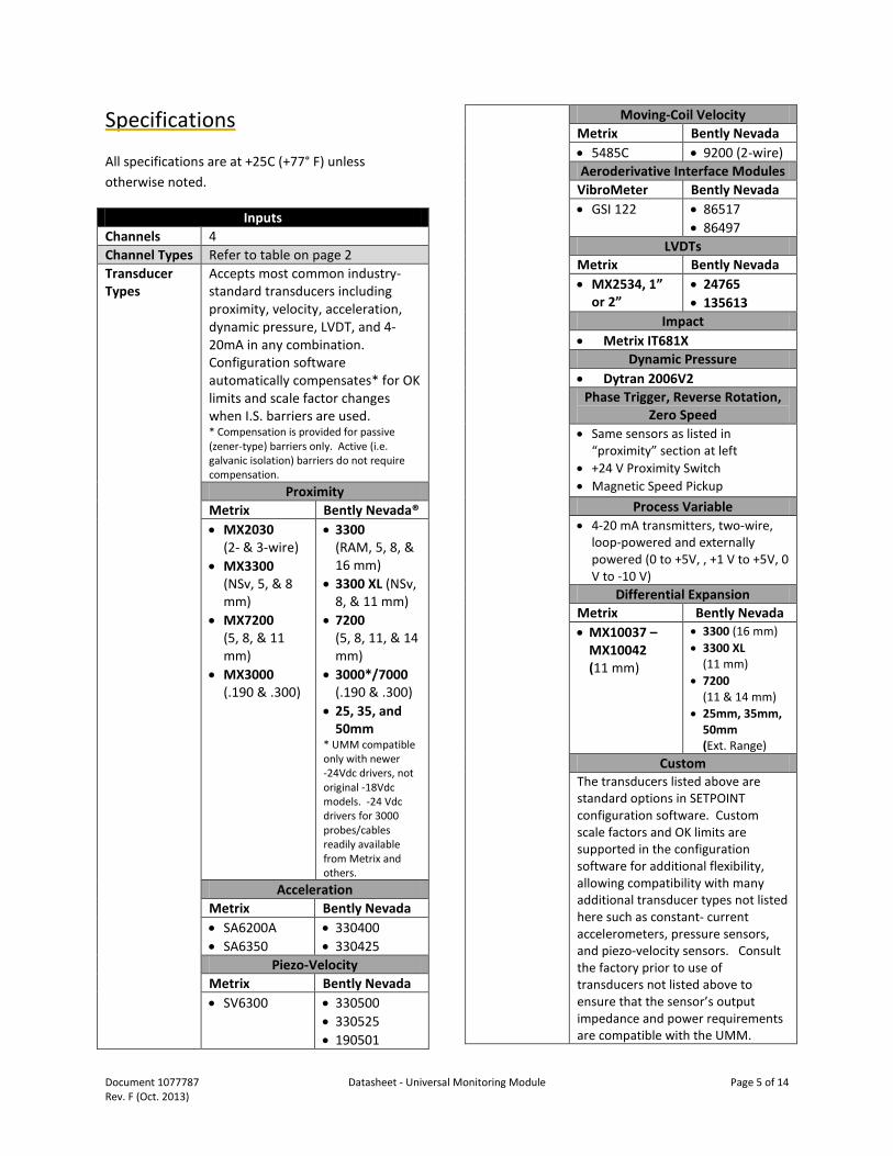
Specifications
All specifications are at +25C (+77° F) unless otherwise noted.
Inputs Channels 4 Channel Types Refer to table on page 2 Transducer Types
Accepts most common industry-standard transducers including proximity, velocity, acceleration, dynamic pressure, LVDT, and 4-20mA in any combination. Configuration software automatically compensates* for OK limits and scale factor changes when I.S. barriers are used. * Compensation is provided for passive (zener-type) barriers only. Active (i.e. galvanic isolation) barriers do not require compensation.
Proximity Metrix Bently Nevada® • MX2030
(2- & 3-wire) • MX3300
(NSv, 5, & 8 mm)
• MX7200 (5, 8, & 11 mm)
• MX3000 (.190 & .300)
• 3300 (RAM, 5, 8, & 16 mm)
• 3300 XL (NSv, 8, & 11 mm)
• 7200 (5, 8, 11, & 14 mm)
• 3000*/7000 (.190 & .300)
• 25, 35, and 50mm
* UMM compatible only with newer -24Vdc drivers, not original -18Vdc models. -24 Vdc drivers for 3000 probes/cables readily available from Metrix and others.
Acceleration Metrix Bently Nevada • SA6200A • SA6350
• 330400 • 330425
Piezo-Velocity Metrix Bently Nevada • SV6300 • 330500
• 330525 • 190501
Moving-Coil Velocity Metrix Bently Nevada • 5485C • 9200 (2-wire) Aeroderivative Interface Modules
VibroMeter Bently Nevada • GSI 122 • 86517
• 86497 LVDTs
Metrix Bently Nevada • MX2534, 1”
or 2” • 24765 • 135613
Impact • Metrix IT681X
Dynamic Pressure • Dytran 2006V2
Phase Trigger, Reverse Rotation, Zero Speed
• Same sensors as listed in “proximity” section at left
• +24 V Proximity Switch • Magnetic Speed Pickup
Process Variable • 4-20 mA transmitters, two-wire,
loop-powered and externally powered (0 to +5V, , +1 V to +5V, 0 V to -10 V)
Differential Expansion Metrix Bently Nevada • MX10037 –
MX10042 (11 mm)
• 3300 (16 mm) • 3300 XL
(11 mm) • 7200
(11 & 14 mm) • 25mm, 35mm,
50mm (Ext. Range)
Custom The transducers listed above are standard options in SETPOINT configuration software. Custom scale factors and OK limits are supported in the configuration software for additional flexibility, allowing compatibility with many additional transducer types not listed here such as constant- current accelerometers, pressure sensors, and piezo-velocity sensors. Consult the factory prior to use of transducers not listed above to ensure that the sensor’s output impedance and power requirements are compatible with the UMM.
Document 1077787 Datasheet - Universal Monitoring Module Page 6 of 14 Rev. F (Oct. 2013)
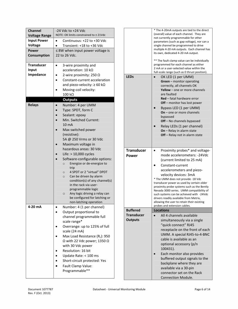
Channel Voltage Range
-24 Vdc to +24 Vdc NOTE: OK limits constrained to ± 21Vdc
Input Power Voltage
• Continuous: +22 to +30 Vdc • Transient: +18 to +36 Vdc
Power Consumption
≤ 8W when input power voltage is 22 to 26 Vdc.
Transducer Input Impedance
• 3-wire proximity and acceleration: 10 kΩ
• 2-wire proximity: 250 Ω • Constant-current acceleration
and piezo-velocity: ≥ 60 kΩ • Moving-coil velocity:
100 kΩ Outputs
Relays • Number: 4 per UMM • Type: SPDT, form C • Sealant: epoxy • Min. Switched Current:
10 mA • Max switched power
(resistive): 5A @ 250 Vrms or 30 Vdc
• Maximum voltage in hazardous areas: 30 Vdc
• Life: > 10,000 cycles • Software-configurable options:
o Energize or de-energize to trip
o 4 SPDT or 2 “virtual” DPDT o Can be driven by alarm
condition(s) of any channel(s) in the rack via user-programmable logic
o Any logic driving a relay can be configured for latching or non-latching operation
4-20 mA • Number: 4 (1 per channel) • Output proportional to
channel programmable full scale range*
• Overrange: up to 125% of full scale (24 mA)
• Max Load Resistance (RL): 950 Ω with 22 Vdc power; 1350 Ω with 30 Vdc power
• Resolution: 16 bit • Update Rate: < 100 ms • Short-circuit protected: Yes • Fault Clamp Value:
Programmable**
* The 4-20mA outputs are tied to the direct (overall) value of each channel. They are not currently programmable for other parameters (such as gap voltage), nor can a single channel be programmed to drive multiple 4-20 mA outputs. Each channel has its own, dedicated 4-20 mA output. ** The fault clamp value can be individually programmed for each channel as either 2 mA or a user-selected value within the full-scale range (such as 0 thrust position).
LEDs • OK LED (1 per UMM) Green – monitor operating correctly, all channels OK Yellow – one or more channels are faulted Red – fatal hardware error Off – monitor has lost power
• Bypass LED (1 per UMM) On – one or more channels bypassed Off – No channels bypassed
• Relay LEDs (1 per channel) On – Relay in alarm state Off – Relay not in alarm state
Transducer Power
• Proximity probes* and voltage-mode accelerometers: -24Vdc (current limited to 25 mA)
• Constant-current accelerometers and piezo-velocity devices: 3mA
* The UMM does not provide -18 Vdc transducer power as used by certain older proximity probe systems such as the Bently Nevada 3000 series. UMM compatibility of such systems can be achieved with -24Vdc drivers readily available from Metrix, allowing the user to retain their existing probes and extension cables.
Buffered Transducer Outputs
Locations • All 4 channels available
simultaneously via a single “quick connect” RJ45 receptacle on the front of each UMM. A special RJ45-to-4-BNC cable is available as an optional accessory (p/n 100431).
• Each monitor also provides buffered output signals to the backplane where they are available via a 30-pin connector set on the Rack Connection Module.
Document 1077787 Datasheet - Universal Monitoring Module Page 7 of 14 Rev. F (Oct. 2013)
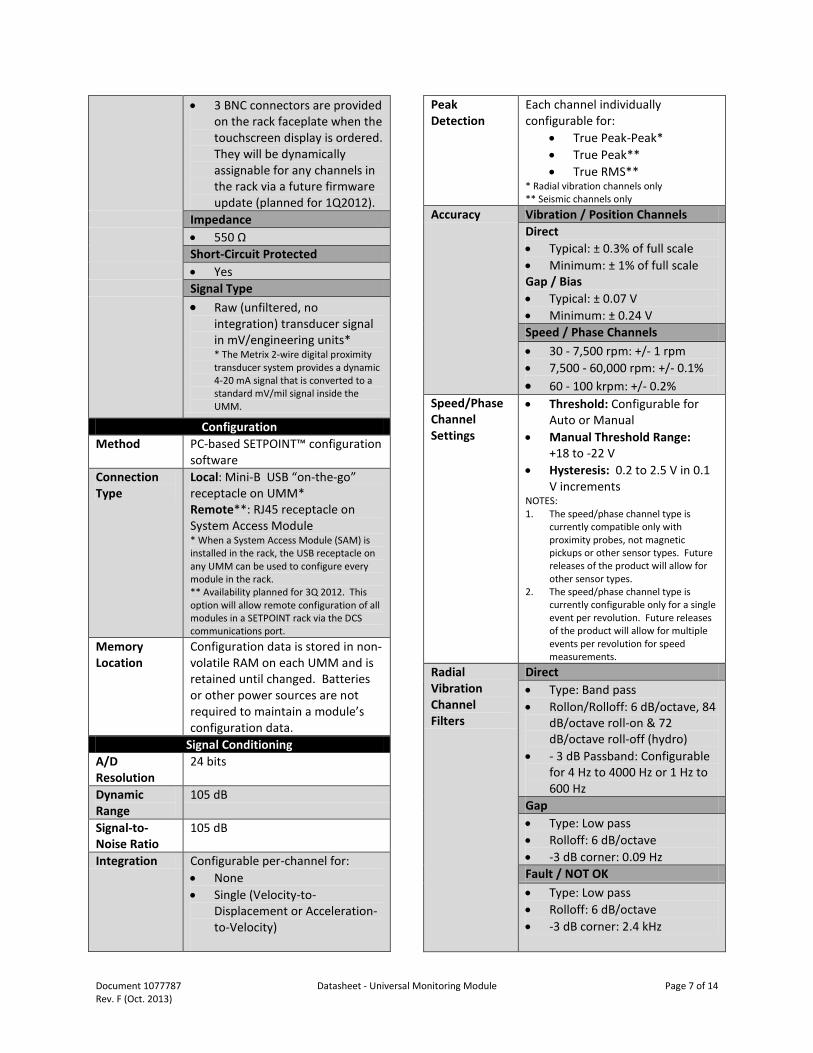
• 3 BNC connectors are provided on the rack faceplate when the touchscreen display is ordered. They will be dynamically assignable for any channels in the rack via a future firmware update (planned for 1Q2012).
Impedance • 550 Ω Short-Circuit Protected • Yes Signal Type • Raw (unfiltered, no
integration) transducer signal in mV/engineering units* * The Metrix 2-wire digital proximity transducer system provides a dynamic 4-20 mA signal that is converted to a standard mV/mil signal inside the UMM.
Configuration Method PC-based SETPOINT™ configuration
software Connection Type
Local: Mini-B USB “on-the-go” receptacle on UMM* Remote**: RJ45 receptacle on System Access Module * When a System Access Module (SAM) is installed in the rack, the USB receptacle on any UMM can be used to configure every module in the rack. ** Availability planned for 3Q 2012. This option will allow remote configuration of all modules in a SETPOINT rack via the DCS communications port.
Memory Location
Configuration data is stored in non-volatile RAM on each UMM and is retained until changed. Batteries or other power sources are not required to maintain a module’s configuration data.
Signal Conditioning A/D Resolution
24 bits
Dynamic Range
105 dB
Signal-to-Noise Ratio
105 dB
Integration Configurable per-channel for: • None • Single (Velocity-to-
Displacement or Acceleration-to-Velocity)
Peak Detection
Each channel individually configurable for:
• True Peak-Peak* • True Peak** • True RMS**
* Radial vibration channels only ** Seismic channels only
Accuracy Vibration / Position Channels Direct • Typical: ± 0.3% of full scale • Minimum: ± 1% of full scale Gap / Bias • Typical: ± 0.07 V • Minimum: ± 0.24 V Speed / Phase Channels • 30 - 7,500 rpm: +/- 1 rpm • 7,500 - 60,000 rpm: +/- 0.1% • 60 - 100 krpm: +/- 0.2%
Speed/Phase Channel Settings
• Threshold: Configurable for Auto or Manual
• Manual Threshold Range: +18 to -22 V
• Hysteresis: 0.2 to 2.5 V in 0.1 V increments
NOTES: 1. The speed/phase channel type is
currently compatible only with proximity probes, not magnetic pickups or other sensor types. Future releases of the product will allow for other sensor types.
2. The speed/phase channel type is currently configurable only for a single event per revolution. Future releases of the product will allow for multiple events per revolution for speed measurements.
Radial Vibration Channel Filters
Direct • Type: Band pass • Rollon/Rolloff: 6 dB/octave, 84
dB/octave roll-on & 72 dB/octave roll-off (hydro)
• - 3 dB Passband: Configurable for 4 Hz to 4000 Hz or 1 Hz to 600 Hz
Gap • Type: Low pass • Rolloff: 6 dB/octave • -3 dB corner: 0.09 Hz Fault / NOT OK • Type: Low pass • Rolloff: 6 dB/octave • -3 dB corner: 2.4 kHz
Document 1077787 Datasheet - Universal Monitoring Module Page 8 of 14 Rev. F (Oct. 2013)
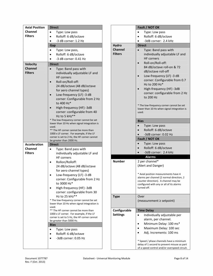
Axial Position Channel Filters
Direct • Type: Low pass • Rolloff: 6 dB/octave • -3 dB corner: 1.2 Hz Gap • Type: Low pass, • Rolloff: 6 dB/octave • -3 dB corner: 0.41 Hz
Velocity Channel Filters
Direct • Type: Band pass with
individually adjustable LF and HF corners
• Roll-on/Roll-off: 24 dB/octave (48 dB/octave for aero channel types)
• Low-frequency (LF) -3 dB corner: Configurable from 2 Hz to 400 Hz*
• High-frequency (HF) -3dB corner: configurable from 40 Hz to 5 kHz**
* The low-frequency corner cannot be set lower than 10 Hz when signal integration is used. ** The HF corner cannot be more than 1000 x LF corner. For example, if the LF corner is set to 2 Hz, the HF corner cannot be greater than 2000 Hz.
Acceleration Channel Filters
Direct • Type: Band pass with
individually adjustable LF and HF corners
• Rollon/Rolloff: 24 dB/octave (48 dB/octave for aero channel types)
• Low-frequency (LF) -3 dB corner: Configurable from 2 Hz to 3000 Hz*
• High-frequency (HF) -3dB corner: configurable from 30 Hz to 25 kHz**
* The low-frequency corner cannot be set lower than 10 Hz when signal integration is used. ** The HF corner cannot be more than 1000 x LF corner. For example, if the LF corner is set to 5 Hz, the HF corner cannot be greater than 5000 Hz. Bias • Type: Low pass • Rolloff: 6 dB/octave • -3dB corner: 0.05 Hz
Fault / NOT OK • Type: Low pass • Rolloff: 6 dB/octave • -3dB corner: 2.4 kHz
Hydro Channel Filters
Direct • Type: Band pass with
individually adjustable LF and HF corners
• Roll-on/Roll-off: 84 dB/octave roll-on & 72 dB/octave roll-off
• Low-frequency (LF) -3 dB corner: Configurable from 0.7 Hz to 200 Hz*
• High-frequency (HF) -3dB corner: configurable from 2 Hz to 200 Hz
* The low-frequency corner cannot be set lower than 10 Hz when signal integration is used. Bias • Type: Low pass • Rolloff: 6 dB/octave • -3dB corner: 0.02 Hz Fault / NOT OK • Type: Low pass • Rolloff: 6 dB/octave • -3dB corner: 2.4 kHz
Alarms Number 2 per channel*
(Alert and Danger) * Axial position measurements have 4 alarms per channel (2 normal direction, 2 counter direction). A channel may be configured with any or all of its alarms turned off.
Type Over (measurement ≥ setpoint)
Configurable Settings
Time Delay • Individually adjustable per
alarm, per channel. • Minimum Delay: 100 ms* • Maximum Delay: 100 sec • Adj. Increments: 100 ms * Speed / phase channels have a minimum delay of 1 second to prevent misuse as part of a speed control and/or overspeed circuit.
Document 1077787 Datasheet - Universal Monitoring Module Page 9 of 14 Rev. F (Oct. 2013)
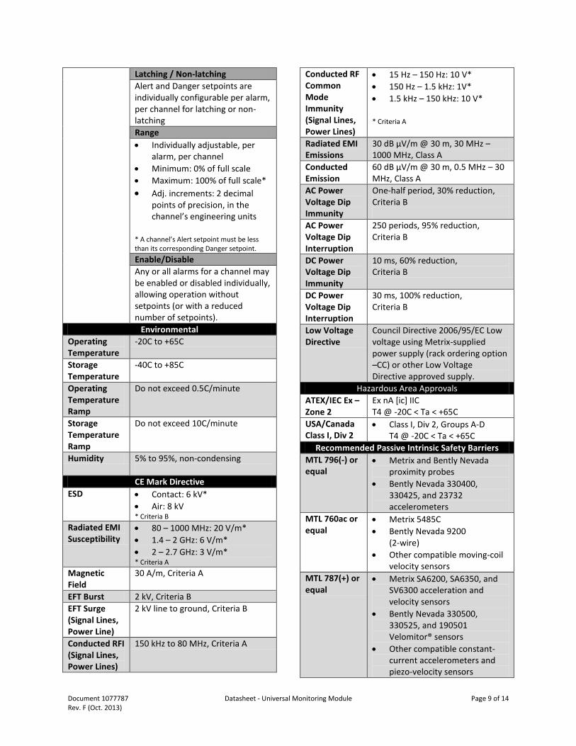
Latching / Non-latching Alert and Danger setpoints are individually configurable per alarm, per channel for latching or non-latching Range • Individually adjustable, per
alarm, per channel • Minimum: 0% of full scale • Maximum: 100% of full scale* • Adj. increments: 2 decimal
points of precision, in the channel’s engineering units
* A channel’s Alert setpoint must be less than its corresponding Danger setpoint. Enable/Disable Any or all alarms for a channel may be enabled or disabled individually, allowing operation without setpoints (or with a reduced number of setpoints).
Environmental Operating Temperature
-20C to +65C
Storage Temperature
-40C to +85C
Operating Temperature Ramp
Do not exceed 0.5C/minute
Storage Temperature Ramp
Do not exceed 10C/minute
Humidity 5% to 95%, non-condensing CE Mark Directive
ESD • Contact: 6 kV* • Air: 8 kV * Criteria B
Radiated EMI Susceptibility
• 80 – 1000 MHz: 20 V/m* • 1.4 – 2 GHz: 6 V/m* • 2 – 2.7 GHz: 3 V/m* * Criteria A
Magnetic Field
30 A/m, Criteria A
EFT Burst 2 kV, Criteria B EFT Surge (Signal Lines, Power Line)
2 kV line to ground, Criteria B
Conducted RFI (Signal Lines, Power Lines)
150 kHz to 80 MHz, Criteria A
Conducted RF Common Mode Immunity (Signal Lines, Power Lines)
• 15 Hz – 150 Hz: 10 V* • 150 Hz – 1.5 kHz: 1V* • 1.5 kHz – 150 kHz: 10 V* * Criteria A
Radiated EMI Emissions
30 dB µV/m @ 30 m, 30 MHz – 1000 MHz, Class A
Conducted Emission
60 dB µV/m @ 30 m, 0.5 MHz – 30 MHz, Class A
AC Power Voltage Dip Immunity
One-half period, 30% reduction, Criteria B
AC Power Voltage Dip Interruption
250 periods, 95% reduction, Criteria B
DC Power Voltage Dip Immunity
10 ms, 60% reduction, Criteria B
DC Power Voltage Dip Interruption
30 ms, 100% reduction, Criteria B
Low Voltage Directive
Council Directive 2006/95/EC Low voltage using Metrix-supplied power supply (rack ordering option –CC) or other Low Voltage Directive approved supply.
Hazardous Area Approvals ATEX/IEC Ex – Zone 2
Ex nA [ic] IIC T4 @ -20C < Ta < +65C
USA/Canada Class I, Div 2
• Class I, Div 2, Groups A-D T4 @ -20C < Ta < +65C
Recommended Passive Intrinsic Safety Barriers MTL 796(-) or equal
• Metrix and Bently Nevada proximity probes
• Bently Nevada 330400, 330425, and 23732 accelerometers
MTL 760ac or equal
• Metrix 5485C • Bently Nevada 9200
(2-wire) • Other compatible moving-coil
velocity sensors MTL 787(+) or equal
• Metrix SA6200, SA6350, and SV6300 acceleration and velocity sensors
• Bently Nevada 330500, 330525, and 190501 Velomitor® sensors
• Other compatible constant-current accelerometers and piezo-velocity sensors
Document 1077787 Datasheet - Universal Monitoring Module Page 10 of 14 Rev. F (Oct. 2013)
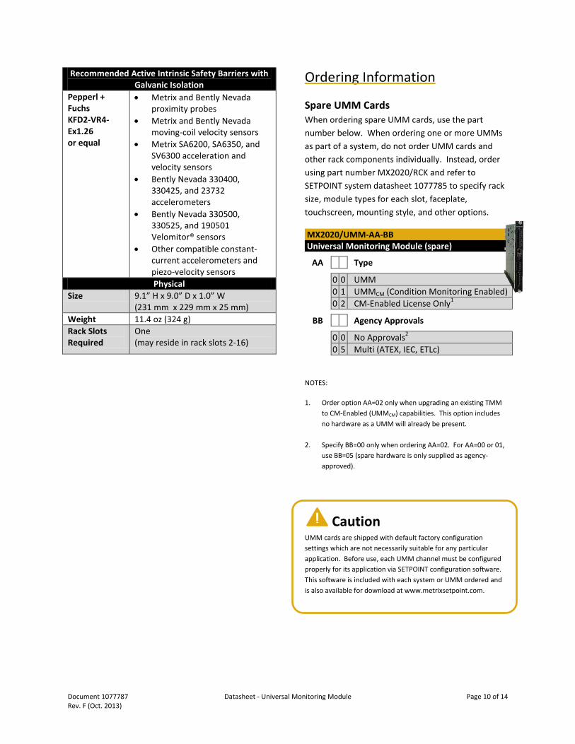
Recommended Active Intrinsic Safety Barriers with Galvanic Isolation
Pepperl + Fuchs KFD2-VR4-Ex1.26 or equal
• Metrix and Bently Nevada proximity probes
• Metrix and Bently Nevada moving-coil velocity sensors
• Metrix SA6200, SA6350, and SV6300 acceleration and velocity sensors
• Bently Nevada 330400, 330425, and 23732 accelerometers
• Bently Nevada 330500, 330525, and 190501 Velomitor® sensors
• Other compatible constant-current accelerometers and piezo-velocity sensors Physical
Size 9.1” H x 9.0” D x 1.0” W (231 mm x 229 mm x 25 mm)
Weight 11.4 oz (324 g) Rack Slots Required
One (may reside in rack slots 2-16)
Ordering Information
Spare UMM Cards When ordering spare UMM cards, use the part number below. When ordering one or more UMMs as part of a system, do not order UMM cards and other rack components individually. Instead, order using part number MX2020/RCK and refer to SETPOINT system datasheet 1077785 to specify rack size, module types for each slot, faceplate, touchscreen, mounting style, and other options.
MX2020/UMM-AA-BB Universal Monitoring Module (spare)
AA Type
0 0 UMM 0 1 UMMCM (Condition Monitoring Enabled) 0 2 CM-Enabled License Only1
BB Agency Approvals
0 0 No Approvals2
0 5 Multi (ATEX, IEC, ETLc)
NOTES:
1. Order option AA=02 only when upgrading an existing TMM to CM-Enabled (UMMCM) capabilities. This option includes no hardware as a UMM will already be present.
2. Specify BB=00 only when ordering AA=02. For AA=00 or 01, use BB=05 (spare hardware is only supplied as agency-approved).
Caution UMM cards are shipped with default factory configuration settings which are not necessarily suitable for any particular application. Before use, each UMM channel must be configured properly for its application via SETPOINT configuration software. This software is included with each system or UMM ordered and is also available for download at www.metrixsetpoint.com.
!

Document 1077787 Datasheet - Universal Monitoring Module Page 11 of 14 Rev. F (Oct. 2013)
Accessories
Breakout Cable* This cable is used when connecting the channels in a single UMM to an external device such as a portable data collector with female BNC jacks. When it is necessary to simultaneously connect channels from multiple UMMs to external instruments, use two or more breakout cables. For ease-of-identification, each BNC connector is numbered under a clear heat-shrink label, corresponding to each UMM channel number. When longer cable runs are required, simply purchase standard CAT5E cable in the desired length and use an RJ45-to-RJ45 inline connector. Both are readily available from a variety of electronics suppliers.
100431-AA BNC breakout cable assembly – RJ45 (male) to four BNC (male)
AA Cable Length
1 0 10 foot (3 m) cable length * NOTE: For systems with programmable BNC jacks on the SETPOINT faceplate, this cable is not required unless simultaneous connection of more than three (3) channels at a time to an external instrument is necessary.
Manuals and Software
A complete set of SETPOINT manuals and configuration software on USB memory stick* is supplied at no extra charge with each order, but must be specified at time of ordering. As languages in addition to English become available, they will be included on the memory stick. The most recent version of manuals and software can also be downloaded directly from our website.
* NOTE: Manuals are published electronically in Adobe® PDF* format and may be printed and freely distributed. Adobe Reader is required and can be downloaded free-of-charge from www.adobe.com. Hardcopy versions of manuals are also available from the factory for an additional charge.
MX2020/CSW-AA SETPOINT Manual and Configuration Software
AA Format
0 1 USB Memory Stick
96014-012** 2m (6’) USB 2.0 A / Mini-B Cable **NOTE: this cable is included with part number MX2020/CSW.
Document 1077787 Datasheet - Universal Monitoring Module Page 12 of 14 Rev. F (Oct. 2013)
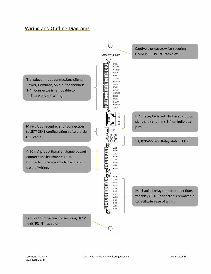
Wiring and Outline Diagrams
W
Transducer Input connections (Signal, Power, Common, Shield) for channels 1-4. Connector is removable to facilitate ease of wiring.
RJ45 receptacle with buffered output signals for channels 1-4 on individual pins.
Mini-B USB receptacle for connection to SETPOINT configuration software via USB cable.
OK, BYPASS, and Relay status LEDs.
4-20 mA proportional analogue output connections for channels 1-4. Connector is removable to facilitate ease of wiring.
Mechanical relay output connections for relays 1-4. Connector is removable to facilitate ease of wiring.
Captive thumbscrew for securing UMM in SETPOINT rack slot.
Captive thumbscrew for securing UMM in SETPOINT rack slot.
Document 1077787 Datasheet - Universal Monitoring Module Page 13 of 14 Rev. F (Oct. 2013)
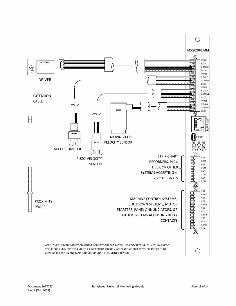
DRIVER
EXTENSION CABLE
PROXIMITY PROBE
ACCELEROMETER
PIEZO-VELOCITY SENSOR
MOVING-COIL VELOCITY SENSOR
STRIP CHART RECORDERS, PLCs,
DCSs, OR OTHER SYSTEMS ACCEPTING 4-
20 mA SIGNALS
MACHINE CONTROL SYSTEMS, SHUTDOWN SYSTEMS, MOTOR
STARTERS, PANEL ANNUNCIATORS, OR OTHER SYSTEMS ACCEPTING RELAY
CONTACTS
NOTE: ONLY SELECTED VIBRATION SENSOR CONNECTIONS ARE SHOWN. FOR DISCRETE INPUT, LVDT, MAGNETIC PICKUP, PROXIMITY SWITCH, AND OTHER SUPPORTED SENSOR / INTERFACE MODULE TYPES, PLEASE REFER TO SETPOINT OPERATION AND MAINTENANCE MANUAL, DOCUMENT # 1079330
Document 1077787 Datasheet - Universal Monitoring Module Page 14 of 14 Rev. F (Oct. 2013)
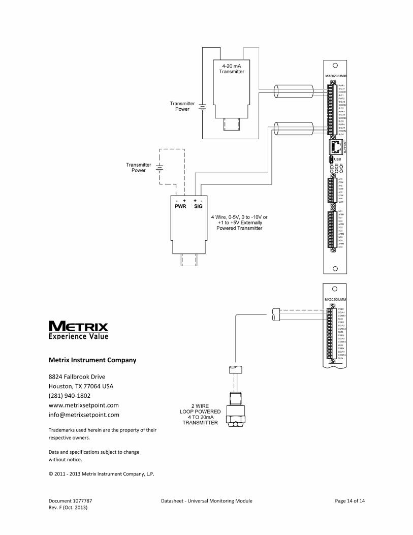
Metrix Instrument Company
8824 Fallbrook Drive Houston, TX 77064 USA (281) 940-1802 www.metrixsetpoint.com [email protected]
Trademarks used herein are the property of their respective owners.
Data and specifications subject to change without notice.
© 2011 - 2013 Metrix Instrument Company, L.P.