Embed Size (px)
Citation preview
www.Fisher.com
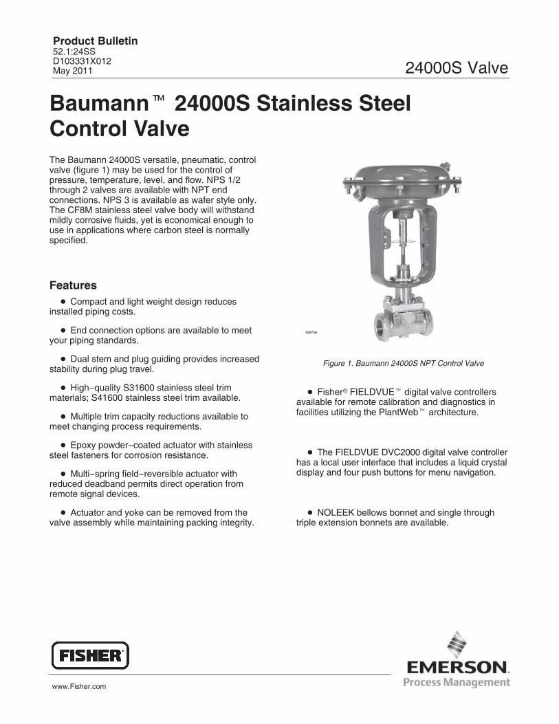
Baumann� 24000S Stainless Steel Control ValveThe Baumann 24000S versatile, pneumatic, controlvalve (figure 1) may be used for the control ofpressure, temperature, level, and flow. NPS 1/2through 2 valves are available with NPT endconnections. NPS 3 is available as wafer style only.The CF8M stainless steel valve body will withstandmildly corrosive fluids, yet is economical enough touse in applications where carbon steel is normallyspecified.
Features� Compact and light weight design reduces
installed piping costs.
� End connection options are available to meetyour piping standards.
� Dual stem and plug guiding provides increasedstability during plug travel.
� High�quality S31600 stainless steel trimmaterials; S41600 stainless steel trim available.
� Multiple trim capacity reductions available tomeet changing process requirements.
� Epoxy powder�coated actuator with stainlesssteel fasteners for corrosion resistance.
� Multi�spring field�reversible actuator withreduced deadband permits direct operation fromremote signal devices.
� Actuator and yoke can be removed from thevalve assembly while maintaining packing integrity.
W9759
Figure 1. Baumann 24000S NPT Control Valve
� Fisher� FIELDVUE� digital valve controllersavailable for remote calibration and diagnostics infacilities utilizing the PlantWeb� architecture.
� The FIELDVUE DVC2000 digital valve controllerhas a local user interface that includes a liquid crystaldisplay and four push buttons for menu navigation.
� NOLEEK bellows bonnet and single throughtriple extension bonnets are available.
Product Bulletin52.1:24SSD103331X012May 2011 24000S Valve
24000S ValveProduct Bulletin
52.1:24SSMay 2011
2
E1266
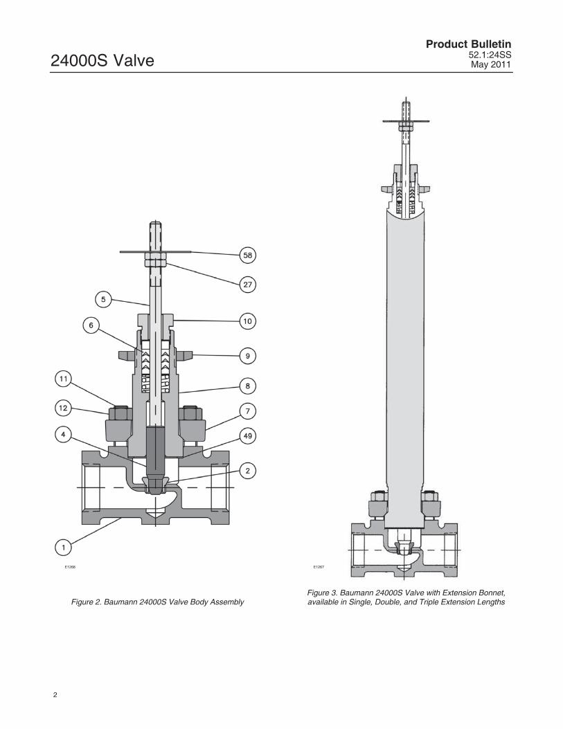
Figure 2. Baumann 24000S Valve Body Assembly
E1267
Figure 3. Baumann 24000S Valve with Extension Bonnet,available in Single, Double, and Triple Extension Lengths
24000S ValveProduct Bulletin52.1:24SSMay 2011
3
Table 1. Materials of ConstructionKeyNo.
Description Material
1 Valve Body ASTM A351, CF8M
2 Seat RingASTM A276 S31600
(used for 6.3 mm and 9.5 mm [1/4 inch and 3/8 inch] orifice diameters only)
4
Plug (Metal Seat) Cv < 2.5Standard ASTM A479 S21800 Annealed
Optional ASTM A582 S41600 Condition T
Plug (Metal Seat) Cv > 4.0Standard ASTM A276 S31600 Condition A
Optional ASTM A582 S41600 Condition T
Plug (Soft Seat)ASTM A276 S31600 Condition A
with PTFE (Polytetrafluoroethylene) Insert
5 Stem ASTM A276 S31600 Condition A
6 Packing Set (Refer to page 5)
7 Bonnet Flange1/2 to 2 inch ASTM A351 CF8M
3 inch ASTM A240 S31600
8 Bonnet
Standard ASTM A479 S31600
Extension ASTM A479 S31600
NOLEEK ASTM A479 S31600
9 Drive Nut (Yoke) S31600 (ASTM A194 Grade 8M)
10 Packing Follower ASTM A276 S31600 Condition A
11 Bonnet Studs (Bolt) ASTM A193 GRADE B8, CLASS 1 S30400
12 Bonnet Nuts ASTM F594 ALLOY GROUP 1, Condition CW S30400
27 Locknuts Stainless Steel (18�8 Stainless Steel)
49 Body Gasket Graphite Grade GHR with S31600 Insert
58 Travel Indicator ASTM A240 S30400
E1268
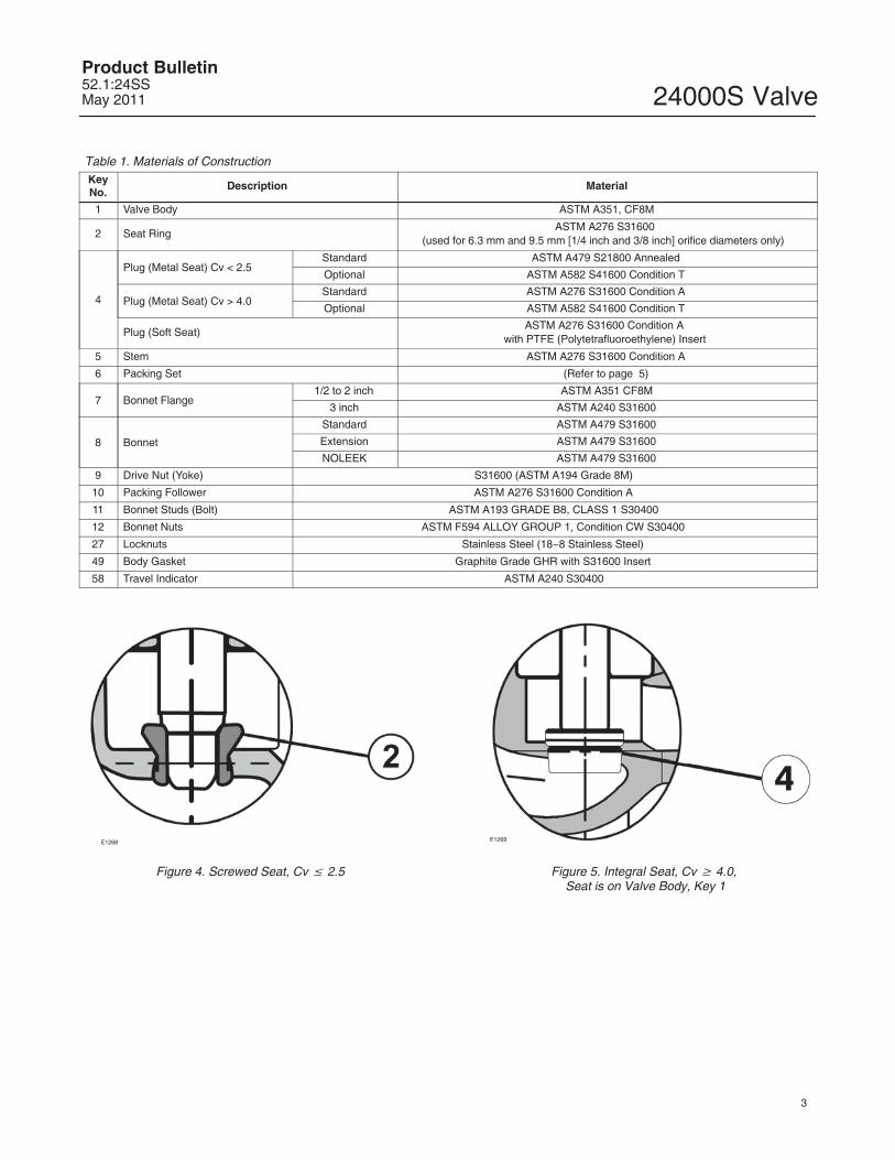
Figure 4. Screwed Seat, Cv � 2.5
E1269
Figure 5. Integral Seat, Cv � 4.0, Seat is on Valve Body, Key 1
24000S ValveProduct Bulletin
52.1:24SSMay 2011
4
E1270
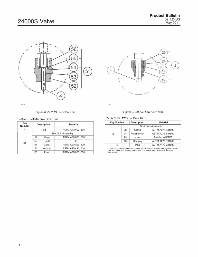
Figure 6. 24151S Low Flow Trim
Table 2. 24151S Low Flow TrimKey
NumberDescription Material
4 Plug ASTM A479 S21800
51
Seat Sub�Assembly
52 Cage ASTM A276 S31600
53 Seat PTFE
54 Collar ASTM A276 S31600
55 Washer ASTM A276 S31600
56 Insert ASTM A276 S31600
E1271
Figure 7. 24177S Low Flow Trim
Table 3. 24177S Low Flow Trim(1)
Key Number Description Material
2
Seat Sub�Assembly
23 Gland ASTM A276 S31600
24 Retainer Nut ASTM A276 S31600
25 Insert Reinforced PTFE
26 Housing ASTM A276 S31600
4 Plug ASTM A479 S218001. For optional trim materials, consult your Emerson Process Management salesoffice for price and delivery. Baumann 32 actuator requires dual�stops with 177trim series.
24000S ValveProduct Bulletin52.1:24SSMay 2011
5
E1240
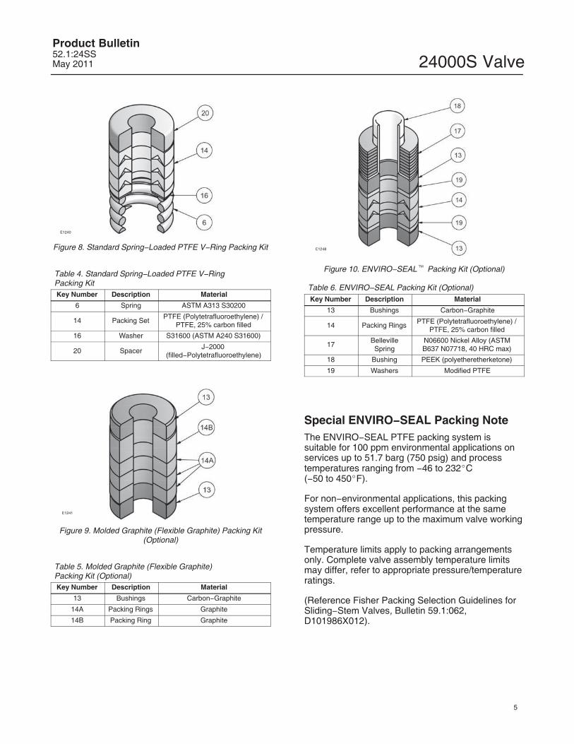
Figure 8. Standard Spring�Loaded PTFE V�Ring Packing Kit
Table 4. Standard Spring�Loaded PTFE V�Ring Packing KitKey Number Description Material
6 Spring ASTM A313 S30200
14 Packing Set PTFE (Polytetrafluoroethylene) /PTFE, 25% carbon filled
16 Washer S31600 (ASTM A240 S31600)
20 Spacer J�2000 (filled�Polytetrafluoroethylene)
E1241
Figure 9. Molded Graphite (Flexible Graphite) Packing Kit(Optional)
Table 5. Molded Graphite (Flexible Graphite) Packing Kit (Optional)Key Number Description Material
13 Bushings Carbon�Graphite
14A Packing Rings Graphite
14B Packing Ring Graphite
E1248
Figure 10. ENVIRO�SEAL� Packing Kit (Optional)
Table 6. ENVIRO�SEAL Packing Kit (Optional)Key Number Description Material
13 Bushings Carbon�Graphite
14 Packing Rings PTFE (Polytetrafluoroethylene) /PTFE, 25% carbon filled
17 BellevilleSpring
N06600 Nickel Alloy (ASTMB637 N07718, 40 HRC max)
18 Bushing PEEK (polyetheretherketone)
19 Washers Modified PTFE
Special ENVIRO�SEAL Packing NoteThe ENVIRO�SEAL PTFE packing system issuitable for 100 ppm environmental applications onservices up to 51.7 barg (750 psig) and processtemperatures ranging from �46 to 232�C (�50 to 450�F).
For non�environmental applications, this packingsystem offers excellent performance at the sametemperature range up to the maximum valve workingpressure.
Temperature limits apply to packing arrangementsonly. Complete valve assembly temperature limitsmay differ, refer to appropriate pressure/temperatureratings.
(Reference Fisher Packing Selection Guidelines forSliding�Stem Valves, Bulletin 59.1:062,D101986X012).
24000S ValveProduct Bulletin
52.1:24SSMay 2011
6
E1272
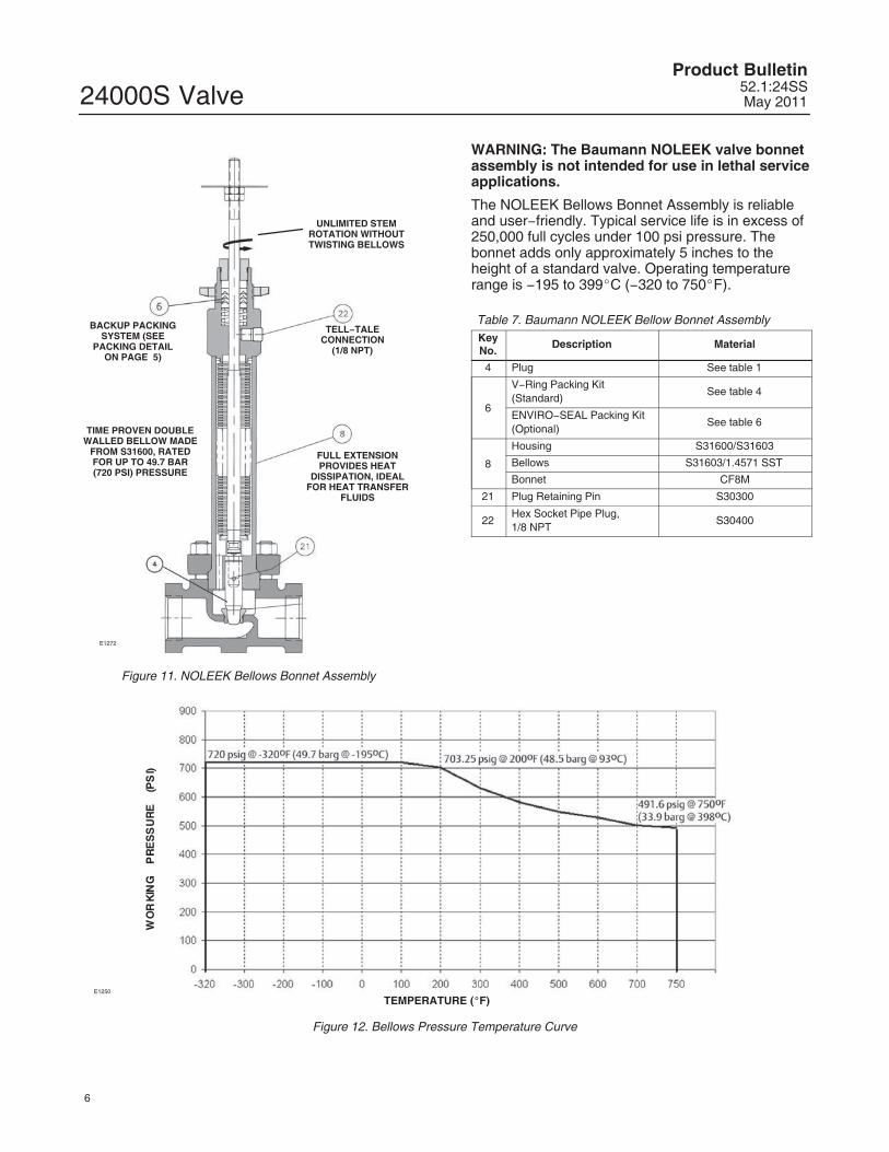
UNLIMITED STEMROTATION WITHOUTTWISTING BELLOWS
TELL�TALECONNECTION
(1/8 NPT)
FULL EXTENSIONPROVIDES HEAT
DISSIPATION, IDEALFOR HEAT TRANSFER
FLUIDS
BACKUP PACKINGSYSTEM (SEE
PACKING DETAILON PAGE 5)
TIME PROVEN DOUBLEWALLED BELLOW MADE
FROM S31600, RATEDFOR UP TO 49.7 BAR(720 PSI) PRESSURE
Figure 11. NOLEEK Bellows Bonnet Assembly
WARNING: The Baumann NOLEEK valve bonnetassembly is not intended for use in lethal serviceapplications.
The NOLEEK Bellows Bonnet Assembly is reliableand user�friendly. Typical service life is in excess of250,000 full cycles under 100 psi pressure. Thebonnet adds only approximately 5 inches to theheight of a standard valve. Operating temperaturerange is �195 to 399�C (�320 to 750�F).
Table 7. Baumann NOLEEK Bellow Bonnet AssemblyKeyNo.
Description Material
4 Plug See table 1
6
V�Ring Packing Kit(Standard)
See table 4
ENVIRO�SEAL Packing Kit(Optional)
See table 6
8
Housing S31600/S31603
Bellows S31603/1.4571 SST
Bonnet CF8M
21 Plug Retaining Pin S30300
22Hex Socket Pipe Plug, 1/8 NPT
S30400
E1250
TEMPERATURE (�F)
Figure 12. Bellows Pressure Temperature Curve
24000S ValveProduct Bulletin52.1:24SSMay 2011
7
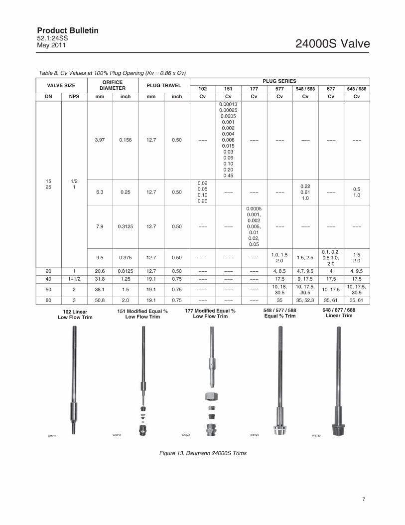
Table 8. Cv Values at 100% Plug Opening (Kv = 0.86 x Cv)
VALVE SIZEORIFICE
DIAMETER PLUG TRAVELPLUG SERIES
102 151 177 577 548 / 588 677 648 / 688
DN NPS mm inch mm inch Cv Cv Cv Cv Cv Cv Cv
1525
1/21
3.97 0.156 12.7 0.50 ���
0.000130.000250.00050.0010.0020.0040.0080.0150.030.060.100.200.45
��� ��� ��� ��� ���
6.3 0.25 12.7 0.50
0.020.050.100.20
��� ��� ���0.220.611.0
��� 0.51.0
7.9 0.3125 12.7 0.50 ��� ���
0.00050.001,0.0020.005,0.010.02,0.05
��� ��� ��� ���
9.5 0.375 12.7 0.50 ��� ��� ��� 1.0, 1.52.0
1.5, 2.50.1, 0.2,0.5 1.0,
2.0
1.52.0
20 1 20.6 0.8125 12.7 0.50 ��� ��� ��� 4, 8.5 4.7, 9.5 4 4, 9.5
40 1�1/2 31.8 1.25 19.1 0.75 ��� ��� ��� 17.5 9, 17.5 17.5 17.5
50 2 38.1 1.5 19.1 0.75 ��� ��� ��� 10, 18,30.5
10, 17.5,30.5
10, 17.5 10, 17.5,30.5
80 3 50.8 2.0 19.1 0.75 ��� ��� ��� 35 35, 52.3 35, 61 35, 61
W9747 W9751 W9748 W9749 W9750
102 LinearLow Flow Trim
151 Modified Equal %Low Flow Trim
177 Modified Equal %Low Flow Trim
548 / 577 / 588Equal % Trim
648 / 677 / 688Linear Trim
Figure 13. Baumann 24000S Trims
24000S ValveProduct Bulletin
52.1:24SSMay 2011
8
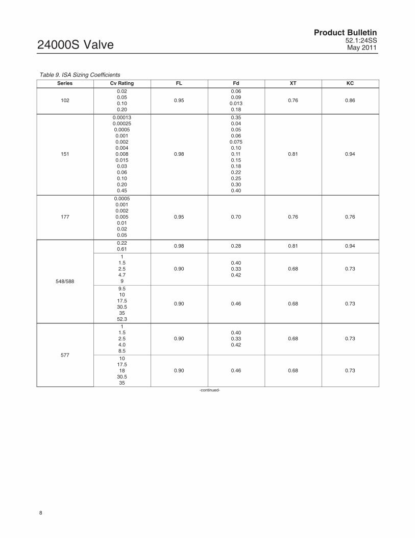
Table 9. ISA Sizing CoefficientsSeries Cv Rating FL Fd XT KC
102
0.020.050.100.20
0.95
0.060.09
0.0130.18
0.76 0.86
151
0.000130.000250.00050.0010.0020.0040.0080.0150.030.060.100.200.45
0.98
0.350.040.050.06
0.0750.100.110.150.180.220.250.300.40
0.81 0.94
177
0.00050.0010.0020.0050.010.020.05
0.95 0.70 0.76 0.76
548/588
0.220.61
0.98 0.28 0.81 0.94
11.52.54.79
0.900.400.330.42
0.68 0.73
9.510
17.530.535
52.3
0.90 0.46 0.68 0.73
577
11.52.54.08.5
0.900.400.330.42
0.68 0.73
1017.518
30.535
0.90 0.46 0.68 0.73
-continued-
24000S ValveProduct Bulletin52.1:24SSMay 2011
9
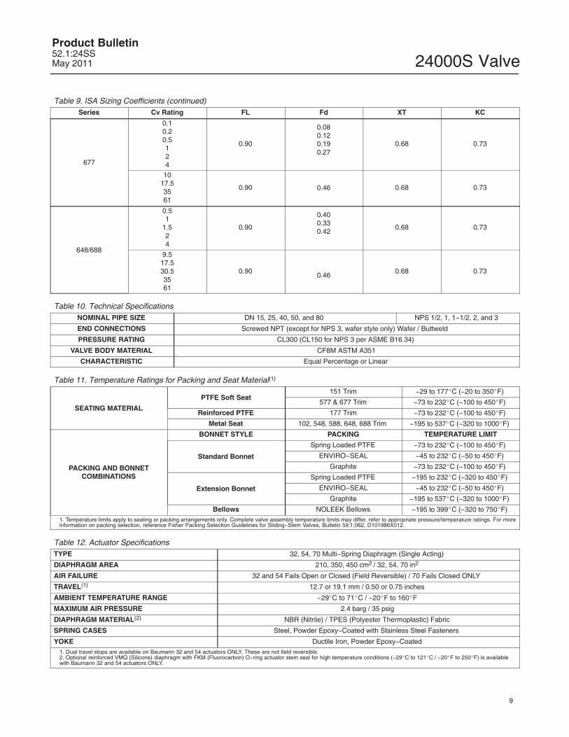
Table 9. ISA Sizing Coefficients (continued)Series Cv Rating FL Fd XT KC
677
0.10.20.5124
0.90
0.080.120.190.27
0.68 0.73
1017.53561
0.90 0.46 0.68 0.73
648/688
0.51
1.524
0.90
0.400.330.42
0.68 0.73
9.517.530.53561
0.900.46
0.68 0.73
Table 10. Technical SpecificationsNOMINAL PIPE SIZE DN 15, 25, 40, 50, and 80 NPS 1/2, 1, 1�1/2, 2, and 3
END CONNECTIONS Screwed NPT (except for NPS 3, wafer style only) Wafer / Buttweld
PRESSURE RATING CL300 (CL150 for NPS 3 per ASME B16.34)
VALVE BODY MATERIAL CF8M ASTM A351
CHARACTERISTIC Equal Percentage or Linear
Table 11. Temperature Ratings for Packing and Seat Material(1)
SEATING MATERIAL
PTFE Soft Seat151 Trim �29 to 177�C (�20 to 350�F)
577 & 677 Trim �73 to 232�C (�100 to 450�F)
Reinforced PTFE 177 Trim �73 to 232�C (�100 to 450�F)
Metal Seat 102, 548, 588, 648, 688 Trim �195 to 537�C (�320 to 1000�F)
PACKING AND BONNETCOMBINATIONS
BONNET STYLE PACKING TEMPERATURE LIMIT
Standard Bonnet
Spring Loaded PTFE �73 to 232�C (�100 to 450�F)
ENVIRO�SEAL �45 to 232�C (�50 to 450�F)
Graphite �73 to 232�C (�100 to 450�F)
Extension Bonnet
Spring Loaded PTFE �195 to 232�C (�320 to 450�F)
ENVIRO�SEAL �45 to 232�C (�50 to 450�F)
Graphite �195 to 537�C (�320 to 1000�F)
Bellows NOLEEK Bellows �195 to 399�C (�320 to 750�F)1. Temperature limits apply to seating or packing arrangements only. Complete valve assembly temperature limits may differ, refer to appropriate pressure/temperature ratings. For moreinformation on packing selection, reference Fisher Packing Selection Guidelines for Sliding�Stem Valves, Bulletin 59.1:062, D101986X012.
Table 12. Actuator SpecificationsTYPE 32, 54, 70 Multi�Spring Diaphragm (Single Acting)
DIAPHRAGM AREA 210, 350, 450 cm2 / 32, 54, 70 in2
AIR FAILURE 32 and 54 Fails Open or Closed (Field Reversible) / 70 Fails Closed ONLY
TRAVEL(1) 12.7 or 19.1 mm / 0.50 or 0.75 inches
AMBIENT TEMPERATURE RANGE �29�C to 71�C / �20�F to 160�F
MAXIMUM AIR PRESSURE 2.4 barg / 35 psig
DIAPHRAGM MATERIAL(2) NBR (Nitrile) / TPES (Polyester Thermoplastic) Fabric
SPRING CASES Steel, Powder Epoxy�Coated with Stainless Steel Fasteners
YOKE Ductile Iron, Powder Epoxy�Coated1. Dual travel stops are available on Baumann 32 and 54 actuators ONLY. These are not field reversible.2. Optional reinforced VMQ (Silicone) diaphragm with FKM (Fluorocarbon) O�ring actuator stem seal for high temperature conditions (�29�C to 121�C / �20�F to 250�F) is availablewith Baumann 32 and 54 actuators ONLY.
24000S ValveProduct Bulletin
52.1:24SSMay 2011
10
E1426
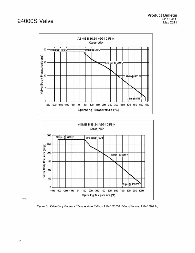
Figure 14. Valve Body Pressure / Temperature Ratings ASME CL150 Valves (Source: ASME B16.34)
24000S ValveProduct Bulletin52.1:24SSMay 2011
11
E1427
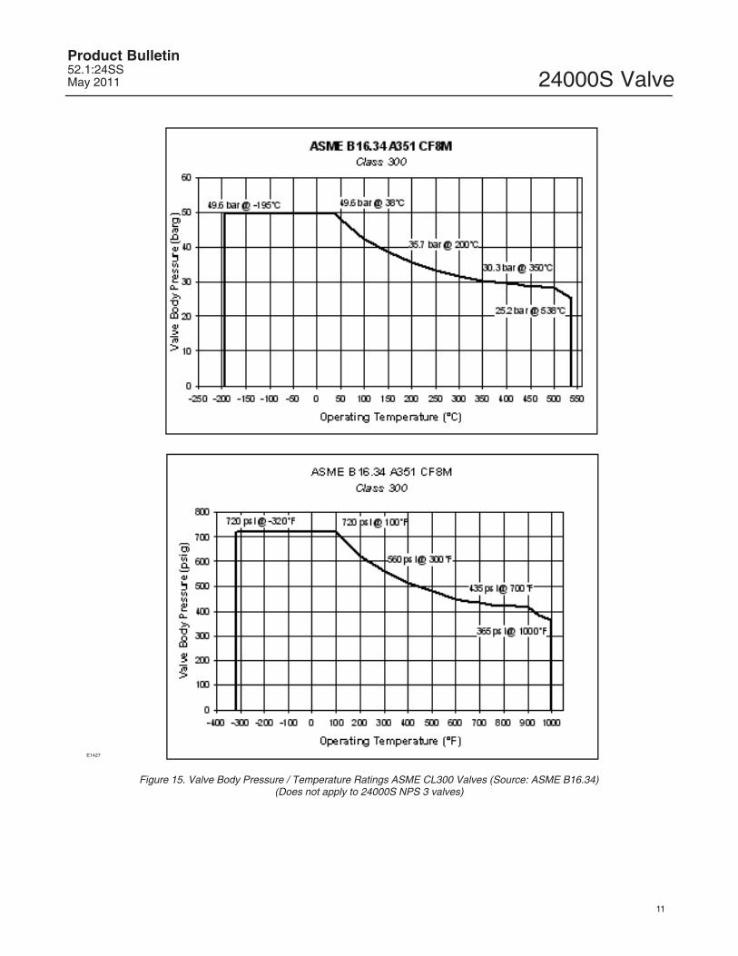
Figure 15. Valve Body Pressure / Temperature Ratings ASME CL300 Valves (Source: ASME B16.34)(Does not apply to 24000S NPS 3 valves)
24000S ValveProduct Bulletin
52.1:24SSMay 2011
12
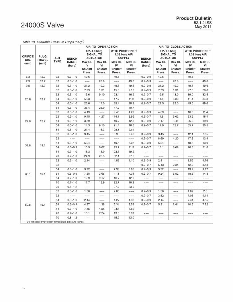
Table 13. Allowable Pressure Drops (bar)(1)
ORIFICEDIA.(mm)
PLUGTRAVEL
(mm)
ACTTYPE
AIR�TO�OPEN ACTION AIR�TO�CLOSE ACTION
BENCHRANGE(barg)
0.2�1.0 bargSIGNAL TOACTUATOR
WITH POSITIONER1.38 barg AIR
SUPPLY BENCHRANGE(barg)
0.2�1.0 bargSIGNAL TOACTUATOR
WITH POSITIONER1.38 barg AIR
SUPPLYMax CL
IVShutoffPress.
Max CLVI
ShutoffPress.
Max CLIV
ShutoffPress.
Max CLVI
ShutoffPress.
Max CLIV
ShutoffPress.
Max CLVI
ShutoffPress.
Max CLIV
ShutoffPress.
Max CLVI
ShutoffPress.
6.3 12.7 32 0.3�1.0 49.6 ��� 49.6 ��� 0.2�0.9 49.6 ��� 49.6 ���
7.9 12.7 32 0.3�1.0 ��� 28.8 ��� 49.6 0.2�0.9 ��� 28.8 ��� 49.6
9.5 12.7 32 0.3�1.0 31.2 19.2 49.6 49.6 0.2�0.9 31.2 19.2 49.6 49.6
20.6 12.7
32 0.3�1.0 7.79 1.31 15.6 9.10 0.2�0.9 7.79 1.31 27.3 20.8
32 0.5�1.0 15.6 9.10 23.4 16.9 0.2�0.7 19.5 13.0 39.0 32.5
54 0.3�1.0 5.93 ��� 17.7 11.2 0.2�0.9 11.8 5.30 41.4 34.8
54 0.5�1.0 23.6 17.0 35.4 28.9 0.2�0.7 29.5 23.0 49.6 49.6
54 0.6�1.0 35.4 28.9 47.2 40.7 ��� ��� ��� ��� ���
27.0 12.7
32 0.3�1.0 4.19 ��� 9.45 4.27 0.2�0.9 4.69 ��� 16.5 11.4
32 0.5�1.0 9.45 4.27 14.1 8.96 0.2�0.7 11.8 6.62 23.6 18.4
54 0.3�1.0 3.59 ��� 10.7 12.5 0.2�0.9 7.17 2.0 25.0 19.9
54 0.5�1.0 14.3 9.10 21.4 16.3 0.2�0.7 17.9 12.7 35.7 30.5
54 0.6�1.0 21.4 16.3 28.5 23.4 ��� ��� ��� ��� ���
31.8 19.1
32 0.3�1.0 3.45 ��� 6.96 2.48 0.2�0.9 3.45 ��� 12.1 7.65
32 ��� ��� ��� ��� ��� 0.2�0.7 8.69 4.20 17.3 12.9
54 0.3�1.0 5.24 ��� 10.5 6.07 0.2�0.9 5.24 ��� 18.3 13.9
54 0.5�0.9 10.9 6.07 15.7 11.3 0.2�0.7 13.1 8.69 26.3 21.8
54 0.7�1.0 18.3 13.9 23.6 19.2 ��� ��� ��� ��� ���
70 0.7�1.0 24.9 20.5 32.1 27.6 ��� ��� ��� ��� ���
38.1 19.1
32 0.3�1.0 2.14 ��� 4.89 1.10 0.2�0.9 2.41 ��� 8.55 4.76
32 ��� ��� ��� ��� ��� 0.2�0.7 6.13 2.34 12.2 8.48
54 0.3�1.0 3.72 ��� 7.38 3.65 0.2�0.9 3.72 ��� 19.9 9.17
54 0.5�0.9 7.38 3.65 11.1 7.31 0.2�0.7 9.24 5.52 18.5 14.8
54 0.7�1.0 12.9 9.17 16.7 12.9 ��� ��� ��� ��� ���
70 0.7�1.0 17.7 13.9 22.7 18.9 ��� ��� ��� ��� ���
70 0.8�1.2 ��� ��� 27.7 23.9 ��� ��� ��� ��� ���
50.8 19.1
32 0.3�1.0 1.38 ��� 2.83 ��� 0.2�0.9 1.38 ��� 4.89 2.0
32 ��� ��� ��� ��� ��� 0.2�0.7 3.52 ��� 7.03 4.14
54 0.3�1.0 2.14 ��� 4.27 1.38 0.2�0.9 2.14 ��� 7.44 4.55
54 0.5�0.9 4.27 1.38 6.34 3.52 0.2�0.7 5.31 2.41 10.6 7.72
54 0.7�1.0 7.45 4.55 9.58 6.69 ��� ��� ��� ��� ���
70 0.7�1.0 10.1 7.24 13.0 8.07 ��� ��� ��� ��� ���
70 0.8�1.2 ��� ��� 15.9 13.0 ��� ��� ��� ��� ���1. Do not exceed valve body temperature pressure ratings.

24000S ValveProduct Bulletin52.1:24SSMay 2011
13
Table 14. Allowable Pressure Drops (psi)(1)
ORIFICEDIA. (in)
PLUGTRAVEL
(in)
ACTTYPE
AIR�TO�OPEN ACTION AIR�TO�CLOSE ACTION
BENCHRANGE(psig)
3�15 psig SIGNALTO ACTUATOR
WITH POSITIONER20 psig AIR
SUPPLY BENCHRANGE(psig)
3�15 psig SIGNALTO ACTUATOR
WITH POSITIONER20 psig AIR
SUPPLYMax CL
IVShutoffPress.
Max CLVI
ShutoffPress.
Max CLIV
ShutoffPress.
Max CLVI
ShutoffPress.
Max CLIV
ShutoffPress.
Max CLVI
ShutoffPress.
Max CLIV
ShutoffPress.
Max CLVI
ShutoffPress.
0.25 0.50 32 5�15 720 ��� 720 ��� 3�13 720 ��� 720 ���
0.3125 0.50 32 5�15 ��� 418 ��� 720 3�13 ��� 418 ��� 720
0.375 0.50 32 5�15 452 278 720 720 3�13 452 278 720 720
0.8125 0.50
32 5�15 113 19 226 132 3�13 113 10 396 301
32 7�15 226 132 339 245 3�10 283 188 565 471
54 4�15 86 ��� 257 162 3�13 171 77 600 505
54 7�15 343 248 514 419 3�10 428 334 720 720
54 9�15 514 419 685 591 ��� ��� ��� ��� ���
1.0625 0.50
32 5�15 68 ��� 137 62 3�13 68 ��� 239 165
32 7�15 137 62 205 130 3�10 171 96 342 267
54 4�15 52 ��� 155 81 3�13 104 29 363 288
54 7�15 207 132 311 236 3�10 259 184 518 443
54 9�15 311 236 414 340 ��� ��� ��� ��� ���
1.25 0.75
32 5�15 50 ��� 101 36 3�13 50 ��� 176 111
32 ��� ��� ��� ��� ��� 3�10 126 61 251 187
54 5�15 76 ��� 152 88 3�13 76 ��� 266 202
54 7�13 152 88 228 164 3�10 190 126 381 316
54 10�14 266 202 343 278 ��� ��� ��� ��� ���
70 10�15 362 297 466 401 ��� ��� ��� ��� ���
1.5 0.75
32 5�15 35 ��� 71 16 3�13 35 ��� 124 69
32 ��� ��� ��� ��� ��� 3�10 89 34 177 123
54 5�15 54 ��� 107 53 3�13 54 ��� 188 133
54 7�13 107 53 161 106 3�10 134 80 269 214
54 10�14 188 133 242 187 ��� ��� ��� ��� ���
70 10�15 256 201 329 274 ��� ��� ��� ��� ���
70 12�18 ��� ��� 402 347 ��� ��� ��� ��� ���
2.0 0.75
32 5�15 20 ��� 41 ��� 3�13 20 ��� 71 29
32 ��� ��� ��� ��� ��� 3�10 51 ��� 102 60
54 5�15 31 ��� 62 20 3�13 31 ��� 108 66
54 7�13 62 20 92 51 3�10 77 35 154 112
54 10�14 108 66 139 97 ��� ��� ��� ��� ���
70 10�15 147 105 189 147 ��� ��� ��� ��� ���
70 12�18 ��� ��� 230 189 ��� ��� ��� ��� ���1. Do not exceed valve body temperature pressure ratings.
24000S ValveProduct Bulletin
52.1:24SSMay 2011
14
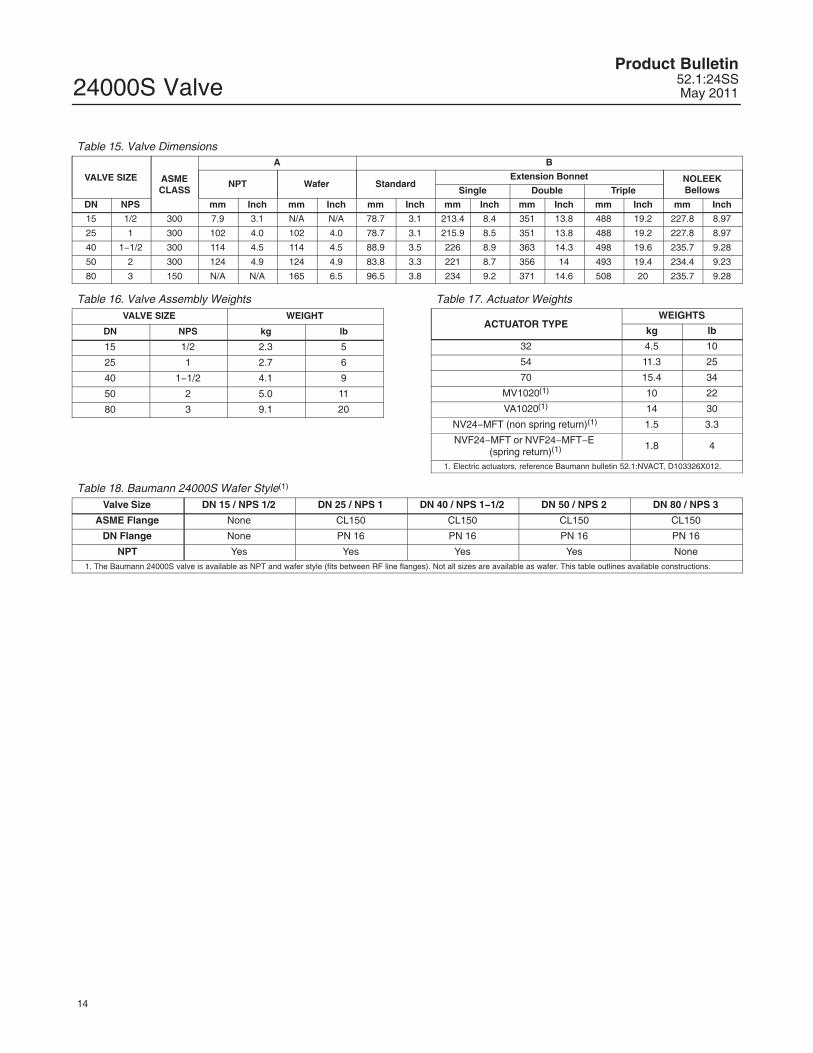
Table 15. Valve Dimensions
VALVE SIZE ASMECLASS
A B
NPT Wafer StandardExtension Bonnet NOLEEK
BellowsSingle Double Triple
DN NPS mm Inch mm Inch mm Inch mm Inch mm Inch mm Inch mm Inch
15 1/2 300 7.9 3.1 N/A N/A 78.7 3.1 213.4 8.4 351 13.8 488 19.2 227.8 8.97
25 1 300 102 4.0 102 4.0 78.7 3.1 215.9 8.5 351 13.8 488 19.2 227.8 8.97
40 1�1/2 300 114 4.5 114 4.5 88.9 3.5 226 8.9 363 14.3 498 19.6 235.7 9.28
50 2 300 124 4.9 124 4.9 83.8 3.3 221 8.7 356 14 493 19.4 234.4 9.23
80 3 150 N/A N/A 165 6.5 96.5 3.8 234 9.2 371 14.6 508 20 235.7 9.28
Table 16. Valve Assembly WeightsVALVE SIZE WEIGHT
DN NPS kg lb
15 1/2 2.3 5
25 1 2.7 6
40 1�1/2 4.1 9
50 2 5.0 11
80 3 9.1 20
Table 17. Actuator Weights
ACTUATOR TYPEWEIGHTS
kg lb
32 4.5 10
54 11.3 25
70 15.4 34
MV1020(1) 10 22
VA1020(1) 14 30
NV24�MFT (non spring return)(1) 1.5 3.3
NVF24�MFT or NVF24�MFT�E (spring return)(1) 1.8 4
1. Electric actuators, reference Baumann bulletin 52.1:NVACT, D103326X012.
Table 18. Baumann 24000S Wafer Style(1)
Valve Size DN 15 / NPS 1/2 DN 25 / NPS 1 DN 40 / NPS 1�1/2 DN 50 / NPS 2 DN 80 / NPS 3
ASME Flange None CL150 CL150 CL150 CL150
DN Flange None PN 16 PN 16 PN 16 PN 16
NPT Yes Yes Yes Yes None1. The Baumann 24000S valve is available as NPT and wafer style (fits between RF line flanges). Not all sizes are available as wafer. This table outlines available constructions.

24000S ValveProduct Bulletin52.1:24SSMay 2011
15
NOTE: ACTUATOR REMOVAL REQUIRES 115 mm (4.5 INCHES) VERTICAL CLEARANCE.NOTE: ELECTRIC ACTUATORS ARE AVAILABLE. CONTACT YOUR EMERSON PROCESS MANAGEMENT SALES OFFICE FOR DETAILS.
216
(�8.5)
279
(�11.0)
333
(�13.1)
141(5.5)
127 (5.0)
276(10.9)
60(2.4)
271(10.7)
229(9.0)
276 (10.9)
E1277
229(9.0)
24000S w/ BAUMANN 32 ATO ACTUATOR
BAUMANN 54 ATO ACTUATOR w/FIELDVUE DVC2000 DIGITAL VALVE
CONTROLLER BAUMANN 70 ATO ACTUATOR w/ FIELDVUEDVC6000 DIGITAL VALVE CONTROLLER
BAUMANN 32 ATC/FAILOPEN ACTUATOR
WITH HANDWHEEL
BAUMANN 54 ATC / FAILOPEN ACTUATOR WITH
HANDWHEEL
160
(�6.3)
31 (1.24)
163 (6.4)MAX
BAUMANN 32 ATO/FAIL CLOSEACTUATOR WITH HANDWHEEL
216
(�8.5)
160
(�6.3)
130 (5.1)MAX
71 (2.8)MAX
94 (3.7)MAX
152
(�6.0)
125 (4.9)
284 (11.2)
NV ELECTRIC ACTUATORmm
(inch)
BAUMANN 54 ATO/FAIL CLOSEACTUATOR WITH HANDWHEEL
BAUMANN 32 ACTUATOR WITH ADJUSTABLEOPEN/CLOSE DUAL TRAVEL STOPS
Figure 16. Dimensional Drawings
24000S ValveProduct Bulletin
52.1:24SSMay 2011
16
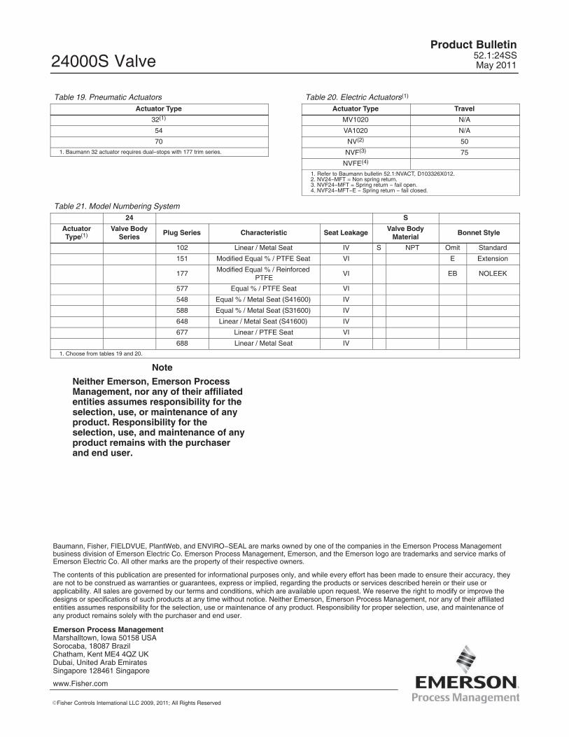
Table 19. Pneumatic ActuatorsActuator Type
32(1)
54
701. Baumann 32 actuator requires dual�stops with 177 trim series.
Table 20. Electric Actuators(1)
Actuator Type Travel
MV1020 N/A
VA1020 N/A
NV(2) 50
NVF(3) 75
NVFE(4)
1. Refer to Baumann bulletin 52.1:NVACT, D103326X012.2. NV24�MFT = Non spring return.3. NVF24�MFT = Spring return � fail open.4. NVF24�MFT�E � Spring return � fail closed.
Table 21. Model Numbering System24 S
ActuatorType(1)
Valve BodySeries
Plug Series Characteristic Seat Leakage Valve BodyMaterial
Bonnet Style
102 Linear / Metal Seat IV S NPT Omit Standard
151 Modified Equal % / PTFE Seat VI E Extension
177 Modified Equal % / ReinforcedPTFE
VI EB NOLEEK
577 Equal % / PTFE Seat VI
548 Equal % / Metal Seat (S41600) IV
588 Equal % / Metal Seat (S31600) IV
648 Linear / Metal Seat (S41600) IV
677 Linear / PTFE Seat VI
688 Linear / Metal Seat IV1. Choose from tables 19 and 20.
Note
Neither Emerson, Emerson ProcessManagement, nor any of their affiliatedentities assumes responsibility for theselection, use, or maintenance of anyproduct. Responsibility for theselection, use, and maintenance of anyproduct remains with the purchaserand end user.
Emerson Process Management Marshalltown, Iowa 50158 USASorocaba, 18087 BrazilChatham, Kent ME4 4QZ UKDubai, United Arab EmiratesSingapore 128461 Singapore
�Fisher Controls International LLC 2009, 2011; All Rights Reserved
www.Fisher.com
The contents of this publication are presented for informational purposes only, and while every effort has been made to ensure their accuracy, theyare not to be construed as warranties or guarantees, express or implied, regarding the products or services described herein or their use orapplicability. All sales are governed by our terms and conditions, which are available upon request. We reserve the right to modify or improve thedesigns or specifications of such products at any time without notice. Neither Emerson, Emerson Process Management, nor any of their affiliatedentities assumes responsibility for the selection, use or maintenance of any product. Responsibility for proper selection, use, and maintenance ofany product remains solely with the purchaser and end user.
Baumann, Fisher, FIELDVUE, PlantWeb, and ENVIRO�SEAL are marks owned by one of the companies in the Emerson Process Managementbusiness division of Emerson Electric Co. Emerson Process Management, Emerson, and the Emerson logo are trademarks and service marks ofEmerson Electric Co. All other marks are the property of their respective owners.