Embed Size (px)
Citation preview
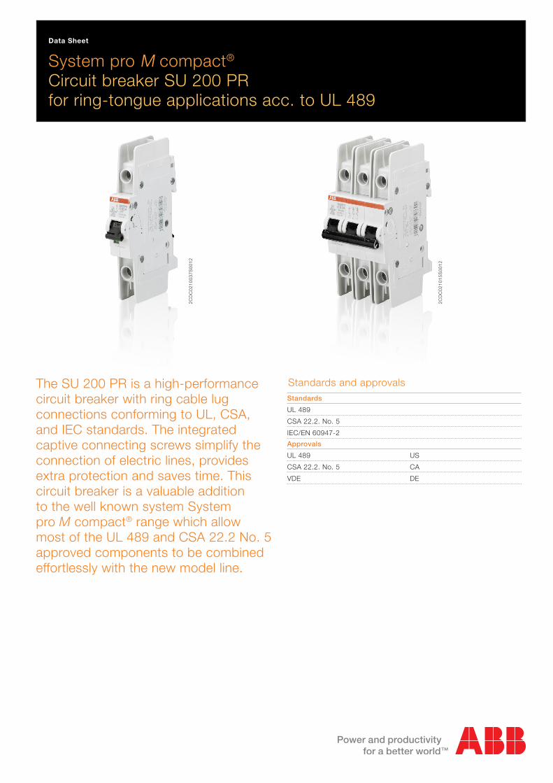
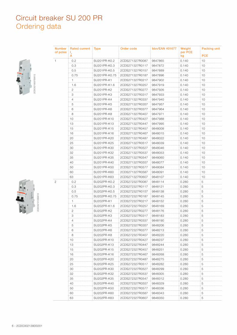
System pro M compact® Circuit breaker SU 200 PRfor ring-tongue applications acc. to UL 489
Data Sheet
The SU 200 PR is a high-performance circuit breaker with ring cable lug connections conforming to UL, CSA, and IEC standards. The integrated captive connecting screws simplify the connection of electric lines, provides extra protection and saves time. This circuit breaker is a valuable addition to the well known system System pro M compact® range which allow most of the UL 489 and CSA 22.2 No. 5 approved components to be combined effortlessly with the new model line.
Standards and approvalsStandards
UL 489
CSA 22.2. No. 5
IEC/EN 60947-2
Approvals
UL 489 US
CSA 22.2. No. 5 CA
VDE DE
2CD
C02
1015
S00
12
2CD
C02
1003
7S00
12
2 - 2CDC002139D0201
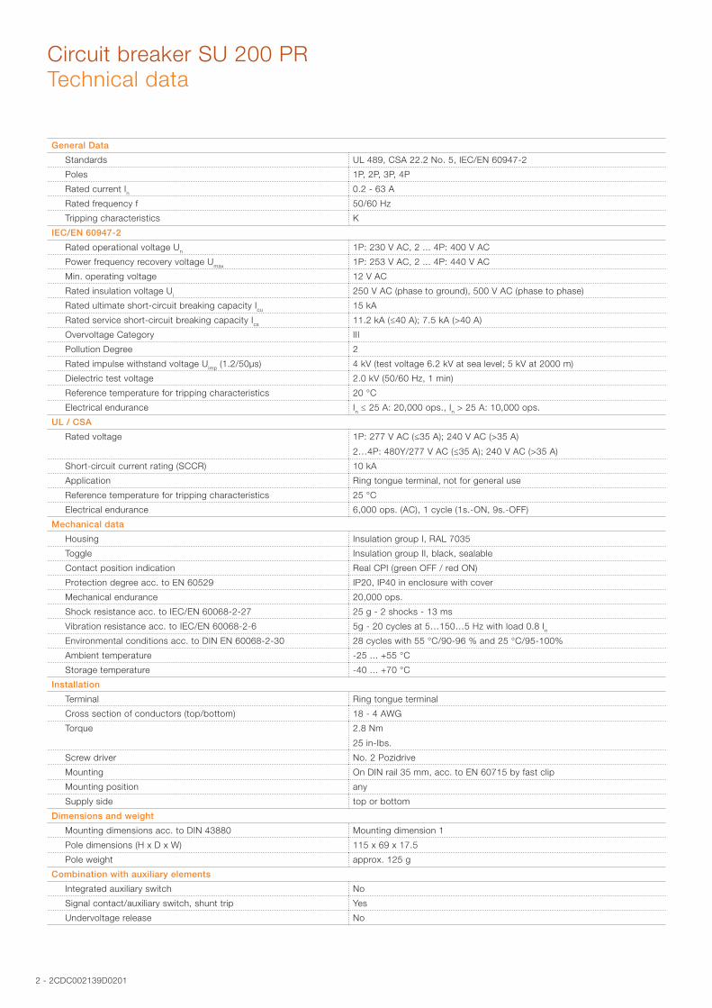
Circuit breaker SU 200 PRTechnical data
General Data
Standards UL 489, CSA 22.2 No. 5, IEC/EN 60947-2
Poles 1P, 2P, 3P, 4P
Rated current In 0.2 - 63 A
Rated frequency f 50/60 Hz
Tripping characteristics K
IEC/EN 60947-2
Rated operational voltage Un 1P: 230 V AC, 2 ... 4P: 400 V AC
Power frequency recovery voltage Umax 1P: 253 V AC, 2 ... 4P: 440 V AC
Min. operating voltage 12 V AC
Rated insulation voltage Ui 250 V AC (phase to ground), 500 V AC (phase to phase)
Rated ultimate short-circuit breaking capacity Icu 15 kA
Rated service short-circuit breaking capacity Ics 11.2 kA (≤40 A); 7.5 kA (>40 A)
Overvoltage Category III
Pollution Degree 2
Rated impulse withstand voltage Uimp (1.2/50µs) 4 kV (test voltage 6.2 kV at sea level; 5 kV at 2000 m)
Dielectric test voltage 2.0 kV (50/60 Hz, 1 min)
Reference temperature for tripping characteristics 20 °C
Electrical endurance In ≤ 25 A: 20,000 ops., In > 25 A: 10,000 ops.
UL / CSA
Rated voltage 1P: 277 V AC (≤35 A); 240 V AC (>35 A)
2…4P: 480Y/277 V AC (≤35 A); 240 V AC (>35 A)
Short-circuit current rating (SCCR) 10 kA
Application Ring tongue terminal, not for general use
Reference temperature for tripping characteristics 25 °C
Electrical endurance 6,000 ops. (AC), 1 cycle (1s.-ON, 9s.-OFF)
Mechanical data
Housing Insulation group I, RAL 7035
Toggle Insulation group II, black, sealable
Contact position indication Real CPI (green OFF / red ON)
Protection degree acc. to EN 60529 IP20, IP40 in enclosure with cover
Mechanical endurance 20,000 ops.
Shock resistance acc. to IEC/EN 60068-2-27 25 g - 2 shocks - 13 ms
Vibration resistance acc. to IEC/EN 60068-2-6 5g - 20 cycles at 5…150…5 Hz with load 0.8 InEnvironmental conditions acc. to DIN EN 60068-2-30 28 cycles with 55 °C/90-96 % and 25 °C/95-100%
Ambient temperature -25 ... +55 °C
Storage temperature -40 ... +70 °C
Installation
Terminal Ring tongue terminal
Cross section of conductors (top/bottom) 18 - 4 AWG
Torque 2.8 Nm
25 in-Ibs.
Screw driver No. 2 Pozidrive
Mounting On DIN rail 35 mm, acc. to EN 60715 by fast clip
Mounting position any
Supply side top or bottom
Dimensions and weight
Mounting dimensions acc. to DIN 43880 Mounting dimension 1
Pole dimensions (H x D x W) 115 x 69 x 17.5
Pole weight approx. 125 g
Combination with auxiliary elements
Integrated auxiliary switch No
Signal contact/auxiliary switch, shunt trip Yes
Undervoltage release No

2CDC002139D0201 - 3
Circuit breaker SU 200 PR
2CD
C 0
22 0
05 F
0211
K characteristic
Tripping characteristic, internal resistance and power loss
1) The thermal releases are calibrated to a nominal reference ambient temperature; for K the reference value is 20 °C. In the case of higher ambient temperatures, the current values fall by approx. 6 % for each 10 K temperature rise.
2) The indicated tripping values of electromagnetic tripping devices apply to a frequency of 50/60 Hz. The thermal release operates independent of frequency.
3) As from operating temperature (after I1 > 1 h or, as applicable, 2 h)
Tripping characteristic K
Internal resistance and power loss
4) Internal resistances and power loss are subject to application-specific and environment-specific conditions and are therefore to be considered as typical values.
Rated current Thermal release 1) Electromagnetic release 2)
In
Currents:conventionalnon-trippingcurrentI1
conventionaltrippingcurrentI2
Tripping time Currents:hold current surges
tripat least at
Tripping time
0.5 to 63 A 1.05 · In1.2 · In
> 1 h
< 1 h not applicable1.05 · In
1.2 · In
> 2 h
< 1 h 3)
10 · In14 · In
> 0.2 s
< 0.2 s
Rated current Internal resistance per pole 4)
Power loss per pole 4)
A mΩ W
0.2 25300 1.01
0.3 13700 1.23
0.5 4740 1.19
0.75 2067 1.16
1 1270 1.27
1.5 610 1.56
2 442 1.77
3 140 1.26
4 109 1.75
5 50 1.26
6 54 1.94
8 22 1.41
10 18.2 1.82
13 14.8 2.50
15 8.1 1.83
16 11.1 2.83
20 8.5 3.40
25 5.5 3.43
30 3.8 3.39
32 4.6 4.70
35 3.9 4.76
40 2.8 4.40
50 1.7 4.25
60 1.7 6.18
63 1.9 7.56

4 - 2CDC002139D0201
Circuit breaker SU 200 PRDerating
Rated current
In
Maximum operating current at ambient temperature T
°C
A –40 °C –30 °C –20 °C –10 °C 0 °C 10 °C 20 °C 30 °C 40 °C 50 °C 60 °C 70 °C
0.5 0.66 0.64 0.61 0.59 0.56 0.53 0.50 0.47 0.43 0.40 0.35 0.31
1.0 1.32 1.27 1.22 1.17 1.12 1.06 1.00 0.94 0.87 0.79 0.71 0.61
1.6 2.12 2.04 1.96 1.88 1.79 1.70 1.60 1.50 1.39 1.26 1.13 0.98
2.0 2.65 2.55 2.45 2.35 2.24 2.12 2.00 1.87 1.73 1.58 1.41 1.22
3.0 4.0 3.8 3.7 3.5 3.4 3.2 3.0 2.8 2.6 2.4 2.1 1.8
4.0 5.3 5.1 4.9 4.7 4.5 4.2 4.0 3.7 3.5 3.2 2.8 2.4
6.0 7.9 7.6 7.3 7.0 6.7 6.4 6.0 5.6 5.2 4.7 4.2 3.7
8.0 10.8 10.2 9.8 9.4 8.9 8.5 8.0 7.5 6.9 6.3 5.7 4.9
10.0 13.2 12.7 12.2 11.7 11.2 10.6 10.0 9.4 8.7 7.9 7.1 6.1
13.0 17.2 16.6 15.9 15.2 14.5 13.8 13.0 12.2 11.3 10.3 9.2 8.0
16.0 21.2 20.4 19.6 18.8 17.9 17.0 16.0 15.0 13.9 12.6 11.3 9.8
20.0 26.5 25.5 24.5 23.5 22.4 21.2 20.0 18.7 17.3 15.8 14.1 12.2
25.0 33.1 31.9 30.6 29.3 28.0 26.5 25.0 23.4 21.7 19.8 17.7 15.3
32.0 42.3 40.8 39.2 37.5 35.8 33.9 32.0 29.9 27.7 25.3 22.6 19.6
40.0 52.9 51.0 49.0 46.9 44.7 42.4 40.0 37.4 34.6 31.6 28.3 24.5
50.0 66.1 63.7 61.2 58.6 55.9 53.0 50.0 46.8 43.3 39.5 35.4 30.6
63.0 83.3 80.3 77.2 73.9 70.4 66.8 63.0 58.9 54.6 49.8 44.5 38.6
For installation of circuit breakers at temperatures that are different from the reference temperature and installations of several circuit breakers directly side by side, derating factors apply to be considered.
Ambient temperatureThe rated value of the current of a circuit breaker with K characteristic refers to a reference ambient temperature of 20 °C.
The following table shows derating factors for ambient temperature from –40 to 70 °C for the characteristic K.
Influence of adjacent devicesIf several miniature circuit breakers are installed directly side by side with high load on all poles, a correction factor has to be applied to the rated current (see table). If distance pieces (spacers) are used, the factor is not to be considered.
No. of adjacent devices Factor F
1 1
2 0.95
3 0.9
4 0.86
5 0.82
6 0.795
7 0.78
8 0.77
9 0.76
>9 0.76

2CDC002139D0201 - 5
Circuit breaker SU 200 PR
Accessory overview
H Auxiliary contact S2C-H6RU
S Signal contact S2C-S6RU
ST Shunt trip S2C-A...U
2CD
C 0
92 0
01 F
0111
Dimensional drawing
Instructions for use
2CD
C 0
22 0
02 F
0011
Accessories, dimensional drawings and instructions for use
6 - 2CDC002139D0201
Circuit breaker SU 200 PR
Number of poles
Rated current In
A
Type Order code bbn/EAN 401677 Weight per PCEkg
Packing unit
PCE
1 0.2 SU201PR-K0.2 2CDS271327R0087 9847865 0.140 10
0.3 SU201PR-K0.3 2CDS271327R0117 9847872 0.140 10
0.5 SU201PR-K0.5 2CDS271327R0157 9847889 0.140 10
0.75 SU201PR-K0.75 2CDS271327R0187 9847896 0.140 10
1 SU201PR-K1 2CDS271327R0217 9847902 0.140 10
1.6 SU201PR-K1.6 2CDS271327R0257 9847919 0.140 10
2 SU201PR-K2 2CDS271327R0277 9847926 0.140 10
3 SU201PR-K3 2CDS271327R0317 9847933 0.140 10
4 SU201PR-K4 2CDS271327R0337 9847940 0.140 10
5 SU201PR-K5 2CDS271327R0357 9847957 0.140 10
6 SU201PR-K6 2CDS271327R0377 9847964 0.140 10
8 SU201PR-K8 2CDS271327R0407 9847971 0.140 10
10 SU201PR-K10 2CDS271327R0427 9847988 0.140 10
13 SU201PR-K13 2CDS271327R0447 9847995 0.140 10
15 SU201PR-K15 2CDS271327R0457 9848008 0.140 10
16 SU201PR-K16 2CDS271327R0467 9848015 0.140 10
20 SU201PR-K20 2CDS271327R0487 9848022 0.140 10
25 SU201PR-K25 2CDS271327R0517 9848039 0.140 10
30 SU201PR-K30 2CDS271327R0527 9848046 0.140 10
32 SU201PR-K32 2CDS271327R0537 9848053 0.140 10
35 SU201PR-K35 2CDS271327R0547 9848060 0.140 10
40 SU201PR-K40 2CDS271327R0557 9848077 0.140 10
50 SU201PR-K50 2CDS271327R0577 9848084 0.140 10
60 SU201PR-K60 2CDS271327R0587 9848091 0.140 10
63 SU201PR-K63 2CDS271327R0607 9848107 0.140 10
2 0.2 SU202PR-K0.2 2CDS272327R0087 9848114 0.280 5
0.3 SU202PR-K0.3 2CDS272327R0117 9848121 0.280 5
0.5 SU202PR-K0.5 2CDS272327R0157 9848138 0.280 5
0.75 SU202PR-K0.75 2CDS272327R0187 9848145 0.280 5
1 SU202PR-K1 2CDS272327R0217 9848152 0.280 5
1.6 SU202PR-K1.6 2CDS272327R0257 9848169 0.280 5
2 SU202PR-K2 2CDS272327R0277 9848176 0.280 5
3 SU202PR-K3 2CDS272327R0317 9848183 0.280 5
4 SU202PR-K4 2CDS272327R0337 9848190 0.280 5
5 SU202PR-K5 2CDS272327R0357 9848206 0.280 5
6 SU202PR-K6 2CDS272327R0377 9848213 0.280 5
8 SU202PR-K8 2CDS272327R0407 9848220 0.280 5
10 SU202PR-K10 2CDS272327R0427 9848237 0.280 5
13 SU202PR-K13 2CDS272327R0447 9848244 0.280 5
15 SU202PR-K15 2CDS272327R0457 9848251 0.280 5
16 SU202PR-K16 2CDS272327R0467 9848268 0.280 5
20 SU202PR-K20 2CDS272327R0487 9848275 0.280 5
25 SU202PR-K25 2CDS272327R0517 9848282 0.280 5
30 SU202PR-K30 2CDS272327R0527 9848299 0.280 5
32 SU202PR-K32 2CDS272327R0537 9848305 0.280 5
35 SU202PR-K35 2CDS272327R0547 9848312 0.280 5
40 SU202PR-K40 2CDS272327R0557 9848329 0.280 5
50 SU202PR-K50 2CDS272327R0577 9848336 0.280 5
60 SU202PR-K60 2CDS272327R0587 9848343 0.280 5
63 SU202PR-K63 2CDS272327R0607 9848350 0.280 5
Ordering data2C
DC
0210
037S
0012
2CD
C02
1012
S00
12

2CDC002139D0201 - 7
Circuit breaker SU 200 PROrdering data
Number of poles
Rated current In
A
Type Order code bbn/EAN 401677 Weight per PCEkg
Paking unit
PCE
3 0.2 SU203PR-K0.2 2CDS273327R0087 9848367 0.420 3
0.3 SU203PR-K0.3 2CDS273327R0117 9848374 0.420 3
0.5 SU203PR-K0.5 2CDS273327R0157 9848381 0.420 3
0.75 SU203PR-K0.75 2CDS273327R0187 9848398 0.420 3
1 SU203PR-K1 2CDS273327R0217 9848404 0.420 3
1.6 SU203PR-K1.6 2CDS273327R0257 9848411 0.420 3
2 SU203PR-K2 2CDS273327R0277 9848428 0.420 3
3 SU203PR-K3 2CDS273327R0317 9848435 0.420 3
4 SU203PR-K4 2CDS273327R0337 9848442 0.420 3
5 SU203PR-K5 2CDS273327R0357 9848459 0.420 3
6 SU203PR-K6 2CDS273327R0377 9848466 0.420 3
8 SU203PR-K8 2CDS273327R0407 9848473 0.420 3
10 SU203PR-K10 2CDS273327R0427 9848480 0.420 3
13 SU203PR-K13 2CDS273327R0447 9848497 0.420 3
15 SU203PR-K15 2CDS273327R0457 9848503 0.420 3
16 SU203PR-K16 2CDS273327R0467 9848510 0.420 3
20 SU203PR-K20 2CDS273327R0487 9848527 0.420 3
25 SU203PR-K25 2CDS273327R0517 9848534 0.420 3
30 SU203PR-K30 2CDS273327R0527 9848541 0.420 3
32 SU203PR-K32 2CDS273327R0537 9848558 0.420 3
35 SU203PR-K35 2CDS273327R0547 9848565 0.420 3
40 SU203PR-K40 2CDS273327R0557 9848572 0.420 3
50 SU203PR-K50 2CDS273327R0577 9848589 0.420 3
60 SU203PR-K60 2CDS273327R0587 9848596 0.420 3
63 SU203PR-K63 2CDS273327R0607 9848602 0.420 3
4 0.2 SU204PR-K0.2 2CDS274327R0087 9848619 0.560 2
0.3 SU204PR-K0.3 2CDS274327R0117 9848626 0.560 2
0.5 SU204PR-K0.5 2CDS274327R0157 9848633 0.560 2
0.75 SU204PR-K0.75 2CDS274327R0187 9848640 0.560 2
1 SU204PR-K1 2CDS274327R0217 9848657 0.560 2
1.6 SU204PR-K1.6 2CDS274327R0257 9848664 0.560 2
2 SU204PR-K2 2CDS274327R0277 9848671 0.560 2
3 SU204PR-K3 2CDS274327R0317 9848688 0.560 2
4 SU204PR-K4 2CDS274327R0337 9848695 0.560 2
5 SU204PR-K5 2CDS274327R0357 9848701 0.560 2
6 SU204PR-K6 2CDS274327R0377 9848718 0.560 2
8 SU204PR-K8 2CDS274327R0407 9848725 0.560 2
10 SU204PR-K10 2CDS274327R0427 9848732 0.560 2
13 SU204PR-K13 2CDS274327R0447 9848749 0.560 2
15 SU204PR-K15 2CDS274327R0457 9848756 0.560 2
16 SU204PR-K16 2CDS274327R0467 9848763 0.560 2
20 SU204PR-K20 2CDS274327R0487 9848770 0.560 2
25 SU204PR-K25 2CDS274327R0517 9848787 0.560 2
30 SU204PR-K30 2CDS274327R0527 9848794 0.560 2
32 SU204PR-K32 2CDS274327R0537 9848800 0.560 2
35 SU204PR-K35 2CDS274327R0547 9848817 0.560 2
40 SU204PR-K40 2CDS274327R0557 9848824 0.560 2
50 SU204PR-K50 2CDS274327R0577 9848831 0.560 2
60 SU204PR-K60 2CDS274327R0587 9848848 0.560 2
63 SU204PR-K63 2CDS274327R0607 9848855 0.560 2
2CD
C02
1015
S00
12
2CD
C02
1014
S00
12

ABB STOTZ-KONTAKT GmbHEppelheimer Straße 82 69123 Heidelberg, Germany Phone: +49 (0) 6221 7 01-0 Fax: +49 (0) 6221 7 01-13 25 E-Mail: [email protected]
You can find the address of your local sales organization on the ABB home page http://www.abb.com/contacts -> Low Voltage Products and Systems
Contact us
Note:We reserve the right to make technical changes or modify the contents of this document without prior notice. With regard to purchase orders, the agreed particulars shall prevail. ABB AG does not accept any responsibility whatsoever for potential errors or possible lack of information in this document.
We reserve all rights in this document and in the subject matter and illustrations contained therein. Any reproduction, disclosure to third parties or utilization of its contents – in whole or in parts – is forbidden without prior written consent of ABB AG.
Copyright© 2012 ABB All rights reserved
Ord
er n
um
ber
2C
DC
0021
39D
020
prin
ted
in G
erm
any
(06/
12-1
-ZV
D)