Embed Size (px)
Citation preview
Skyworks Solutions, Inc. • Phone [781] 376-3000 • Fax [781] 376-3100 • [email protected] • www.skyworksinc.com 202853G • Skyworks Proprietary Information • Products and Product Information are Subject to Change Without Notice • April 3, 2017 1
DATA SHEET
SKY13526-485LF: 0.4 to 3.8 GHz SP6T LTE Transmit/Receive Switch with MIPI RFFE Interface Applications
2G/3G/4G multimode cellular tablets and handsets (LTE, UMTS, CDMA2000, EDGE)
Embedded data cards
Features
Broadband frequency range: 0.4 to 3.8 GHz
Low insertion loss
High isolation and linearity
External MIPI select pin
Six linear TRX ports with isolation greater than 20 dB @ 2.7 GHz
Small QFN (14-pin, 2 x 2 mm) package (MSL1, 260 C per JEDEC J-STD-020)
Skyworks GreenTM products are compliant withall applicable legislation and are halogen-free.For additional information, refer to SkyworksDefinition of GreenTM, document number SQ04–0074.
Description The SKY13526-485LF is a single-pole, six-throw (SP6T) antenna switch with a Mobile Industry Processor Interface (MIPI).
Using advanced switching technologies, the SKY13526-485LF maintains low insertion loss and high isolation for both transmit and receive switching paths. The high linearity performance and low insertion loss achieved by the SKY13526-485LF makes it an ideal choice for UMTS, CDMA2000, EDGE, and LTE applications.
MIPI Decoder
TRX3
TRX4
TRX1
TRX2
TRX5
TRX6
VDD
SCLK
SDAT
A
MIP
I_SE
LECTVIO
ANT
2028
53-0
01
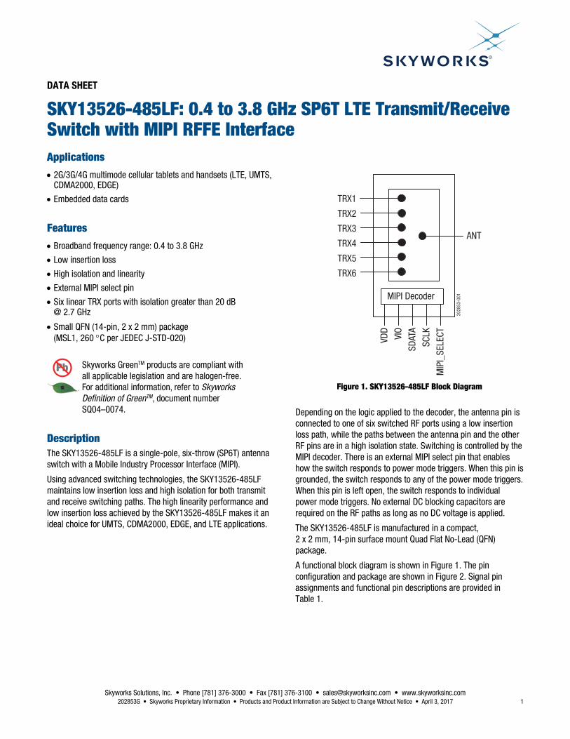
Figure 1. SKY13526-485LF Block Diagram
Depending on the logic applied to the decoder, the antenna pin is connected to one of six switched RF ports using a low insertion loss path, while the paths between the antenna pin and the other RF pins are in a high isolation state. Switching is controlled by the MIPI decoder. There is an external MIPI select pin that enables how the switch responds to power mode triggers. When this pin is grounded, the switch responds to any of the power mode triggers. When this pin is left open, the switch responds to individual power mode triggers. No external DC blocking capacitors are required on the RF paths as long as no DC voltage is applied.
The SKY13526-485LF is manufactured in a compact, 2 x 2 mm, 14-pin surface mount Quad Flat No-Lead (QFN) package.
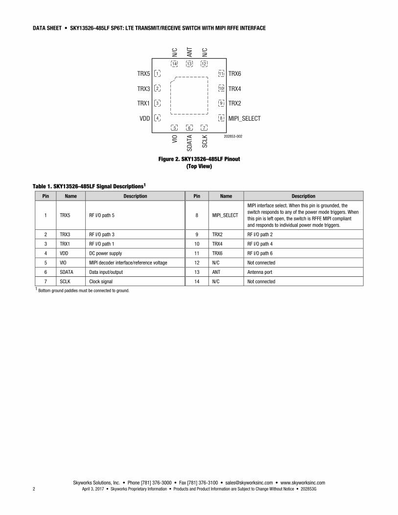
A functional block diagram is shown in Figure 1. The pin configuration and package are shown in Figure 2. Signal pin assignments and functional pin descriptions are provided in Table 1.
DATA SHEET • SKY13526-485LF SP6T: LTE TRANSMIT/RECEIVE SWITCH WITH MIPI RFFE INTERFACE
Skyworks Solutions, Inc. • Phone [781] 376-3000 • Fax [781] 376-3100 • [email protected] • www.skyworksinc.com 2 April 3, 2017 • Skyworks Proprietary Information • Products and Product Information are Subject to Change Without Notice • 202853G
202853-002
1TRX5
TRX3
TRX1
VDD
VIO
SDAT
A
SCLK
N/C
ANT
N/C
TRX6
TRX4
TRX2
MIPI_SELECT
1214 13
75 6
4
3
2
11
8
9
10
Figure 2. SKY13526-485LF Pinout (Top View)
Table 1. SKY13526-485LF Signal Descriptions1
Pin Name Description Pin Name Description
1 TRX5 RF I/O path 5 8 MIPI_SELECT
MIPI interface select. When this pin is grounded, the switch responds to any of the power mode triggers. When this pin is left open, the switch is RFFE MIPI compliant and responds to individual power mode triggers.
2 TRX3 RF I/O path 3 9 TRX2 RF I/O path 2
3 TRX1 RF I/O path 1 10 TRX4 RF I/O path 4
4 VDD DC power supply 11 TRX6 RF I/O path 6
5 VIO MIPI decoder interface/reference voltage 12 N/C Not connected
6 SDATA Data input/output 13 ANT Antenna port
7 SCLK Clock signal 14 N/C Not connected 1 Bottom ground paddles must be connected to ground.
DATA SHEET • SKY13526-485LF SP6T: LTE TRANSMIT/RECEIVE SWITCH WITH MIPI RFFE INTERFACE
Skyworks Solutions, Inc. • Phone [781] 376-3000 • Fax [781] 376-3100 • [email protected] • www.skyworksinc.com 202853G • Skyworks Proprietary Information • Products and Product Information are Subject to Change Without Notice • April 3, 2017 3
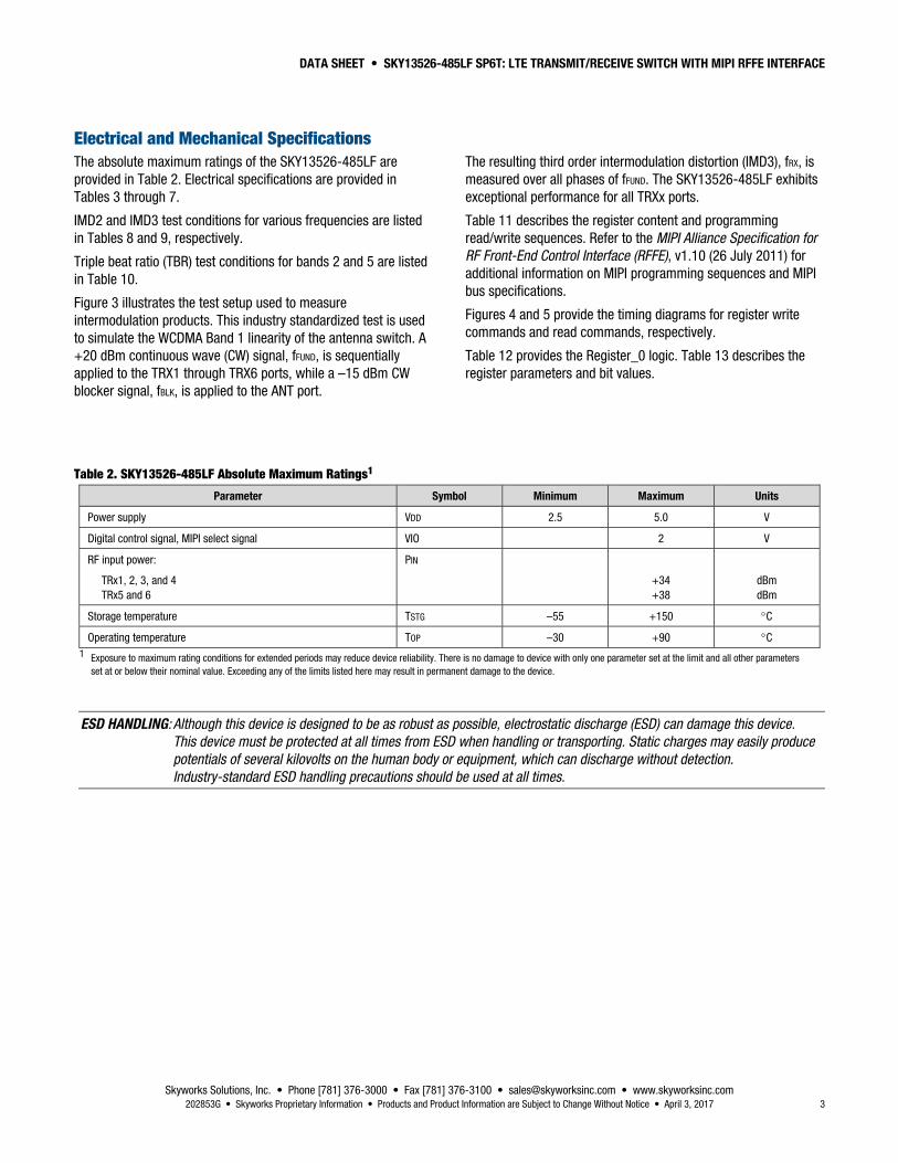
Electrical and Mechanical Specifications The absolute maximum ratings of the SKY13526-485LF are provided in Table 2. Electrical specifications are provided in Tables 3 through 7.
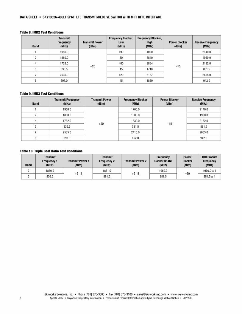
IMD2 and IMD3 test conditions for various frequencies are listed in Tables 8 and 9, respectively.
Triple beat ratio (TBR) test conditions for bands 2 and 5 are listed in Table 10.
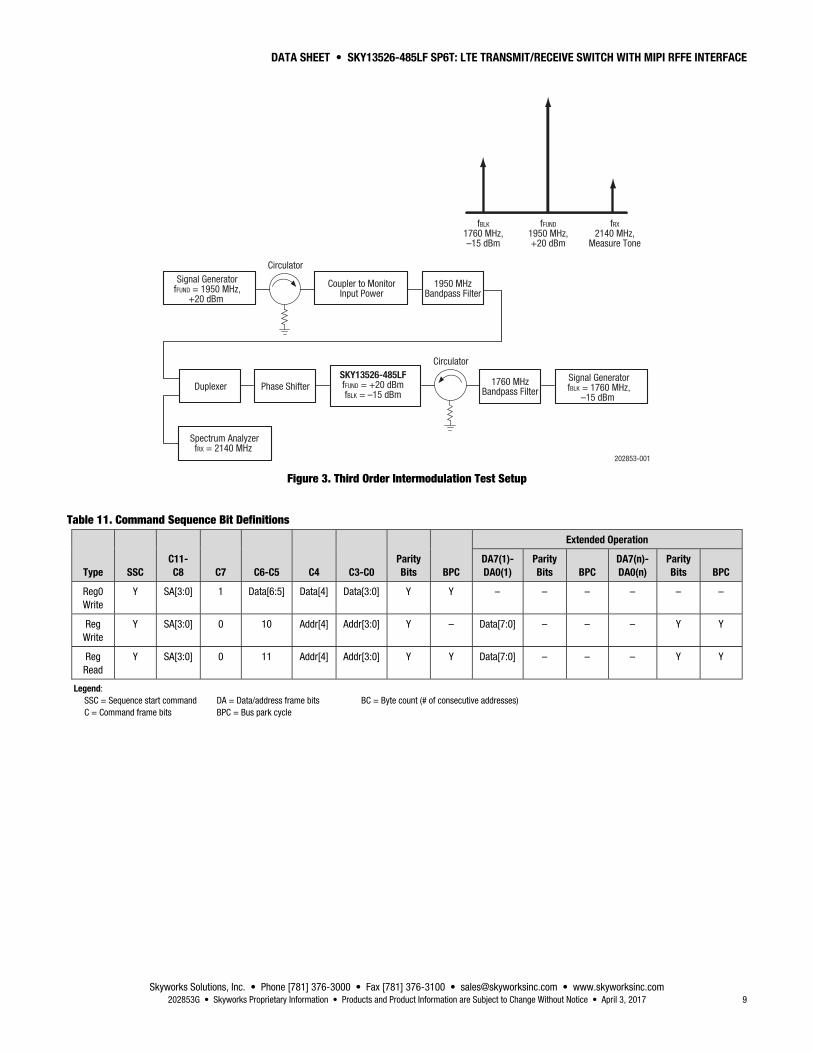
Figure 3 illustrates the test setup used to measure intermodulation products. This industry standardized test is used to simulate the WCDMA Band 1 linearity of the antenna switch. A +20 dBm continuous wave (CW) signal, fFUND, is sequentially applied to the TRX1 through TRX6 ports, while a –15 dBm CW blocker signal, fBLK, is applied to the ANT port.
The resulting third order intermodulation distortion (IMD3), fRX, is measured over all phases of fFUND. The SKY13526-485LF exhibits exceptional performance for all TRXx ports.
Table 11 describes the register content and programming read/write sequences. Refer to the MIPI Alliance Specification for RF Front-End Control Interface (RFFE), v1.10 (26 July 2011) for additional information on MIPI programming sequences and MIPI bus specifications.
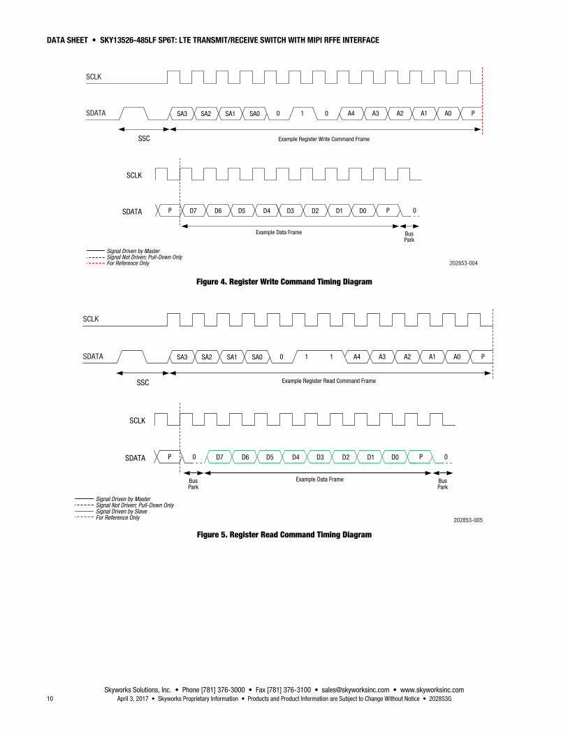
Figures 4 and 5 provide the timing diagrams for register write commands and read commands, respectively.
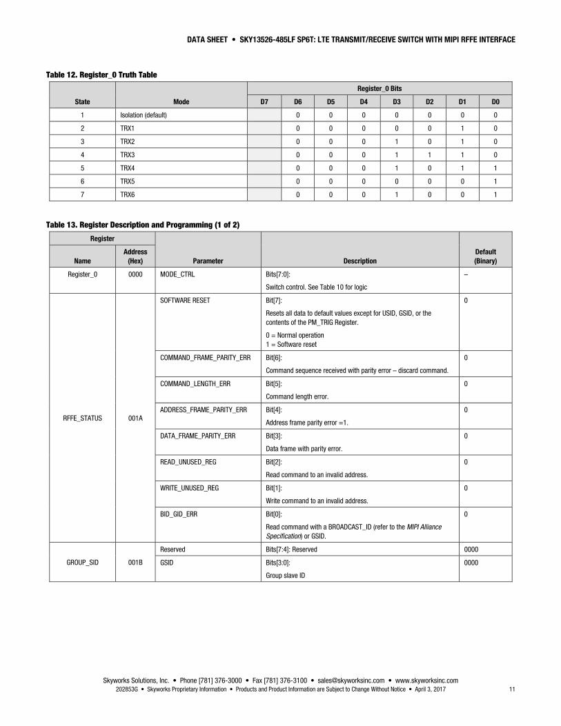
Table 12 provides the Register_0 logic. Table 13 describes the register parameters and bit values.
Table 2. SKY13526-485LF Absolute Maximum Ratings1
Parameter Symbol Minimum Maximum Units
Power supply VDD 2.5 5.0 V
Digital control signal, MIPI select signal VIO 2 V
RF input power:
TRx1, 2, 3, and 4 TRx5 and 6
PIN
+34 +38
dBm dBm
Storage temperature TSTG –55 +150 C
Operating temperature TOP –30 +90 C 1 Exposure to maximum rating conditions for extended periods may reduce device reliability. There is no damage to device with only one parameter set at the limit and all other parameters
set at or below their nominal value. Exceeding any of the limits listed here may result in permanent damage to the device.
ESD HANDLING: Although this device is designed to be as robust as possible, electrostatic discharge (ESD) can damage this device. This device must be protected at all times from ESD when handling or transporting. Static charges may easily produce potentials of several kilovolts on the human body or equipment, which can discharge without detection. Industry-standard ESD handling precautions should be used at all times.
DATA SHEET • SKY13526-485LF SP6T: LTE TRANSMIT/RECEIVE SWITCH WITH MIPI RFFE INTERFACE
Skyworks Solutions, Inc. • Phone [781] 376-3000 • Fax [781] 376-3100 • [email protected] • www.skyworksinc.com 4 April 3, 2017 • Skyworks Proprietary Information • Products and Product Information are Subject to Change Without Notice • 202853G
Table 3. SKY13526-485LF General Electrical Specifications1 (VDD = 2.85 V, VIO = 1.8 V, TOP = +25 C, Characteristic Impedance [ZO] = 50 Ω, Unless Otherwise Noted)
Parameter Symbol Test Condition Min Typ Max Units
Supply voltage VDD 2.50 2.85 4.80 V
Supply current, active mode IDD 35 65 μA
Supply current, low power mode IDD 10 μA
Digital control signal, MIPI select VIO, MS 1.65 1.80 1.95 V
Interface signal:
High Low
0.8 x VIO
0.2 x VIO
V V
Control current:
High Low
10 5
μA μA
Switching time 2 5 μs 1 Performance is guaranteed only under the conditions listed in this table.
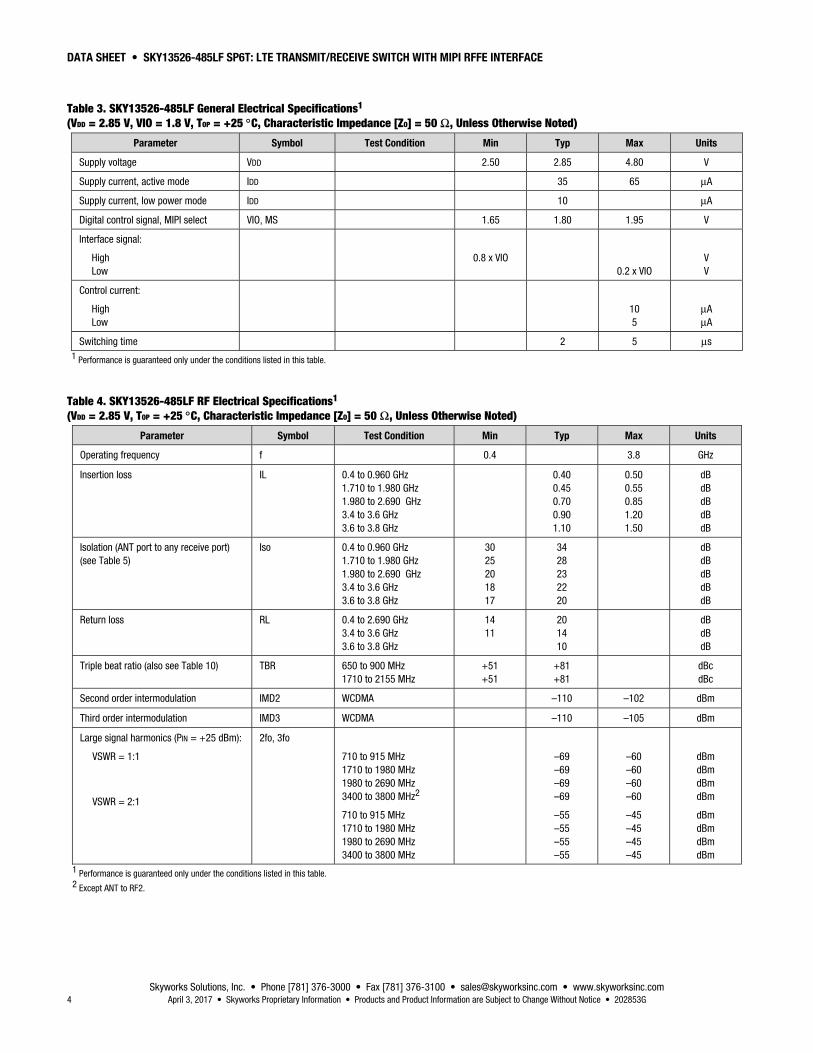
Table 4. SKY13526-485LF RF Electrical Specifications1 (VDD = 2.85 V, TOP = +25 C, Characteristic Impedance [ZO] = 50 Ω, Unless Otherwise Noted)
Parameter Symbol Test Condition Min Typ Max Units
Operating frequency f 0.4 3.8 GHz
Insertion loss IL 0.4 to 0.960 GHz 1.710 to 1.980 GHz 1.980 to 2.690 GHz 3.4 to 3.6 GHz 3.6 to 3.8 GHz
0.40 0.45 0.70 0.90 1.10
0.50 0.55 0.85 1.20 1.50
dB dB dB dB dB
Isolation (ANT port to any receive port) (see Table 5)
Iso 0.4 to 0.960 GHz 1.710 to 1.980 GHz 1.980 to 2.690 GHz 3.4 to 3.6 GHz 3.6 to 3.8 GHz
30 25 20 18 17
34 28 23 22 20
dB dB dB dB dB
Return loss RL 0.4 to 2.690 GHz 3.4 to 3.6 GHz 3.6 to 3.8 GHz
14 11
20 14 10
dB dB dB
Triple beat ratio (also see Table 10) TBR 650 to 900 MHz 1710 to 2155 MHz
+51 +51
+81 +81
dBc dBc
Second order intermodulation IMD2 WCDMA –110 –102 dBm
Third order intermodulation IMD3 WCDMA –110 –105 dBm
Large signal harmonics (PIN = +25 dBm):
VSWR = 1:1
VSWR = 2:1
2fo, 3fo
710 to 915 MHz 1710 to 1980 MHz 1980 to 2690 MHz 3400 to 3800 MHz2
710 to 915 MHz 1710 to 1980 MHz 1980 to 2690 MHz 3400 to 3800 MHz
–69 –69 –69 –69
–55 –55 –55 –55
–60 –60 –60 –60
–45 –45 –45 –45
dBm dBm dBm dBm
dBm dBm dBm dBm
1 Performance is guaranteed only under the conditions listed in this table. 2 Except ANT to RF2.
DATA SHEET • SKY13526-485LF SP6T: LTE TRANSMIT/RECEIVE SWITCH WITH MIPI RFFE INTERFACE
Skyworks Solutions, Inc. • Phone [781] 376-3000 • Fax [781] 376-3100 • [email protected] • www.skyworksinc.com 202853G • Skyworks Proprietary Information • Products and Product Information are Subject to Change Without Notice • April 3, 2017 5
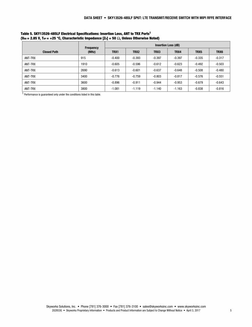
Table 5. SKY13526-485LF Electrical Specifications: Insertion Loss, ANT to TRX Ports1 (VDD = 2.85 V, TOP = +25 °C, Characteristic Impedance [ZO] = 50 Ω, Unless Otherwise Noted)
Closed Path Frequency
(MHz)
Insertion Loss (dB)
TRX1 TRX2 TRX3 TRX4 TRX5 TRX6
ANT-TRX 915 -0.400 -0.393 -0.397 -0.397 -0.335 -0.317
ANT-TRX 1910 -0.605 -0.596 -0.612 -0.623 -0.492 -0.503
ANT-TRX 2690 -0.613 -0.601 -0.637 -0.648 -0.508 -0.480
ANT-TRX 3400 -0.776 -0.759 -0.803 -0.817 -0.576 -0.551
ANT-TRX 3600 -0.896 -0.911 -0.944 -0.953 -0.679 -0.643
ANT-TRX 3800 -1.081 -1.119 -1.140 -1.163 -0.838 -0.816 1 Performance is guaranteed only under the conditions listed in this table.
DATA SHEET • SKY13526-485LF SP6T: LTE TRANSMIT/RECEIVE SWITCH WITH MIPI RFFE INTERFACE
Skyworks Solutions, Inc. • Phone [781] 376-3000 • Fax [781] 376-3100 • [email protected] • www.skyworksinc.com 6 April 3, 2017 • Skyworks Proprietary Information • Products and Product Information are Subject to Change Without Notice • 202853G
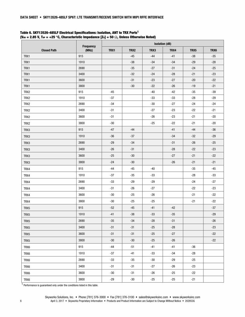
Table 6. SKY13526-485LF Electrical Specifications: Isolation, ANT to TRX Ports1 (VDD = 2.85 V, TOP = +25 C, Characteristic Impedance [ZO] = 50 Ω, Unless Otherwise Noted)
Closed Path Frequency
(MHz)
Isolation (dB)
TRX1 TRX2 TRX3 TRX4 TRX5 TRX6
TRX1 915 -45 -44 -41 -38 -35
TRX1 1910 -38 -34 -34 -29 -28
TRX1 2690 -35 -27 -31 -24 -25
TRX1 3400 -32 -24 -28 -21 -23
TRX1 3600 -31 -23 -27 -20 -22
TRX1 3800 -30 -22 -26 -19 -21
TRX2 915 -45 -40 -42 -35 -39
TRX2 1910 -37 -33 -33 -28 -29
TRX2 2690 -34 -30 -27 -24 -24
TRX2 3400 -31 -27 -23 -22 -21
TRX2 3600 -31 -26 -23 -21 -20
TRX2 3800 -30 -25 -22 -21 -20
TRX3 915 -47 -44 -41 -44 -36
TRX3 1910 -36 -37 -34 -32 -29
TRX3 2690 -29 -34 -31 -26 -25
TRX3 3400 -26 -31 -28 -22 -23
TRX3 3600 -25 -30 -27 -21 -22
TRX3 3800 -24 -30 -26 -21 -21
TRX4 915 -44 -45 -40 -35 -45
TRX4 1910 -37 -35 -33 -28 -33
TRX4 2690 -33 -29 -29 -24 -27
TRX4 3400 -31 -26 -27 -22 -23
TRX4 3600 -30 -25 -26 -21 -22
TRX4 3800 -30 -25 -25 -21 -22
TRX5 915 -52 -45 -41 -42 -37
TRX5 1910 -41 -38 -33 -35 -29
TRX5 2690 -35 -34 -28 -31 -26
TRX5 3400 -31 -31 -25 -28 -23
TRX5 3600 -31 -31 -25 -27 -22
TRX5 3800 -30 -30 -25 -26 -22
TRX6 915 -44 -51 -41 -41 -36
TRX6 1910 -37 -41 -33 -34 -28
TRX6 2690 -33 -35 -30 -29 -25
TRX6 3400 -31 -31 -27 -26 -23
TRX6 3600 -30 -31 -26 -25 -22
TRX6 3800 -29 -30 -25 -25 -21
1 Performance is guaranteed only under the conditions listed in this table.
DATA SHEET • SKY13526-485LF SP6T: LTE TRANSMIT/RECEIVE SWITCH WITH MIPI RFFE INTERFACE
Skyworks Solutions, Inc. • Phone [781] 376-3000 • Fax [781] 376-3100 • [email protected] • www.skyworksinc.com 202853G • Skyworks Proprietary Information • Products and Product Information are Subject to Change Without Notice • April 3, 2017 7
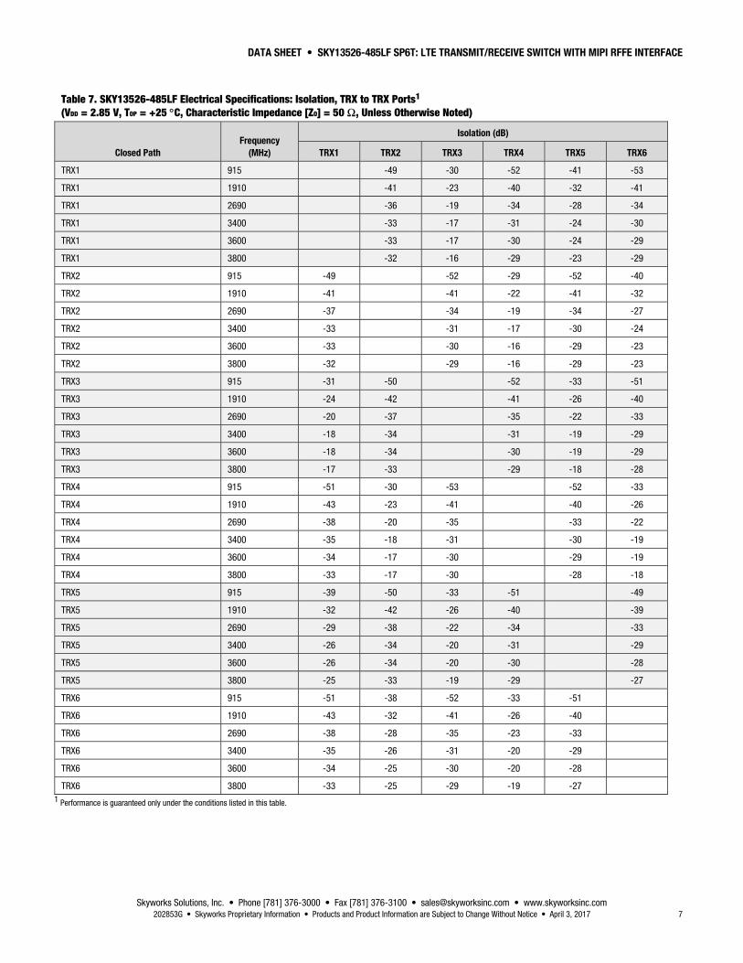
Table 7. SKY13526-485LF Electrical Specifications: Isolation, TRX to TRX Ports1 (VDD = 2.85 V, TOP = +25 C, Characteristic Impedance [ZO] = 50 Ω, Unless Otherwise Noted)
Closed Path Frequency
(MHz)
Isolation (dB)
TRX1 TRX2 TRX3 TRX4 TRX5 TRX6
TRX1 915 -49 -30 -52 -41 -53
TRX1 1910 -41 -23 -40 -32 -41
TRX1 2690 -36 -19 -34 -28 -34
TRX1 3400 -33 -17 -31 -24 -30
TRX1 3600 -33 -17 -30 -24 -29
TRX1 3800 -32 -16 -29 -23 -29
TRX2 915 -49 -52 -29 -52 -40
TRX2 1910 -41 -41 -22 -41 -32
TRX2 2690 -37 -34 -19 -34 -27
TRX2 3400 -33 -31 -17 -30 -24
TRX2 3600 -33 -30 -16 -29 -23
TRX2 3800 -32 -29 -16 -29 -23
TRX3 915 -31 -50 -52 -33 -51
TRX3 1910 -24 -42 -41 -26 -40
TRX3 2690 -20 -37 -35 -22 -33
TRX3 3400 -18 -34 -31 -19 -29
TRX3 3600 -18 -34 -30 -19 -29
TRX3 3800 -17 -33 -29 -18 -28
TRX4 915 -51 -30 -53 -52 -33
TRX4 1910 -43 -23 -41 -40 -26
TRX4 2690 -38 -20 -35 -33 -22
TRX4 3400 -35 -18 -31 -30 -19
TRX4 3600 -34 -17 -30 -29 -19
TRX4 3800 -33 -17 -30 -28 -18
TRX5 915 -39 -50 -33 -51 -49
TRX5 1910 -32 -42 -26 -40 -39
TRX5 2690 -29 -38 -22 -34 -33
TRX5 3400 -26 -34 -20 -31 -29
TRX5 3600 -26 -34 -20 -30 -28
TRX5 3800 -25 -33 -19 -29 -27
TRX6 915 -51 -38 -52 -33 -51
TRX6 1910 -43 -32 -41 -26 -40
TRX6 2690 -38 -28 -35 -23 -33
TRX6 3400 -35 -26 -31 -20 -29
TRX6 3600 -34 -25 -30 -20 -28
TRX6 3800 -33 -25 -29 -19 -27 1 Performance is guaranteed only under the conditions listed in this table.
DATA SHEET • SKY13526-485LF SP6T: LTE TRANSMIT/RECEIVE SWITCH WITH MIPI RFFE INTERFACE
Skyworks Solutions, Inc. • Phone [781] 376-3000 • Fax [781] 376-3100 • [email protected] • www.skyworksinc.com 8 April 3, 2017 • Skyworks Proprietary Information • Products and Product Information are Subject to Change Without Notice • 202853G
Table 8. IMD2 Test Conditions
Band
Transmit Frequency
(MHz) Transmit Power
(dBm)
Frequency Blocker, Low
(MHz)
Frequency Blocker, High
(MHz) Power Blocker
(dBm) Receive Frequency
(MHz)
1 1950.0
+20
190 4090
–15
2140.0
2 1880.0 80 3840 1960.0
4 1732.0 400 3864 2132.0
5 836.5 45 1718 881.5
7 2535.0 120 5187 2655.0
8 897.0 45 1839 942.0
Table 9. IMD3 Test Conditions
Band Transmit Frequency
(MHz) Transmit Power
(dBm) Frequency Blocker
(MHz) Power Blocker
(dBm) Receive Frequency
(MHz)
1 1950.0
+20
1760.0
–15
2140.0
2 1880.0 1800.0 1960.0
4 1732.0 1332.0 2132.0
5 836.5 791.5 881.5
7 2535.0 2415.0 2655.0
8 897.0 852.0 942.0
Table 10. Triple Beat Ratio Test Conditions
Band
Transmit Frequency 1
(MHz) Transmit Power 1
(dBm)
Transmit Frequency 2
(MHz) Transmit Power 2
(dBm)
Frequency Blocker @ ANT
(MHz)
Power Blocker (dBm)
TBR Product Frequency
(MHz)
2 1880.0 +21.5
1881.0 +21.5
1960.0 –30
1960.0 ± 1
5 836.5 881.5 881.5 881.5 ± 1
DATA SHEET • SKY13526-485LF SP6T: LTE TRANSMIT/RECEIVE SWITCH WITH MIPI RFFE INTERFACE
Skyworks Solutions, Inc. • Phone [781] 376-3000 • Fax [781] 376-3100 • [email protected] • www.skyworksinc.com 202853G • Skyworks Proprietary Information • Products and Product Information are Subject to Change Without Notice • April 3, 2017 9
Signal GeneratorfFUND = 1950 MHz,
+20 dBm
Spectrum AnalyzerfRX = 2140 MHz
Signal GeneratorfBLK = 1760 MHz,
–15 dBm
Coupler to MonitorInput Power
Circulator
fBLK
1760 MHz,–15 dBm
fFUND
1950 MHz,+20 dBm
fRX
2140 MHz,Measure Tone
1950 MHzBandpass Filter
1760 MHzBandpass FilterDuplexer Phase Shifter
SKY13526-485LFfFUND = +20 dBmfBLK = –15 dBm
202853-001
Circulator
Figure 3. Third Order Intermodulation Test Setup
Table 11. Command Sequence Bit Definitions
Type SSC C11-C8 C7 C6-C5 C4 C3-C0
Parity Bits BPC
Extended Operation
DA7(1)- DA0(1)
Parity Bits BPC
DA7(n)-DA0(n)
Parity Bits BPC
Reg0 Write
Y SA[3:0] 1 Data[6:5] Data[4] Data{3:0] Y Y – – – – – –
Reg Write
Y SA[3:0] 0 10 Addr[4] Addr[3:0] Y – Data[7:0] – – – Y Y
Reg Read
Y SA[3:0] 0 11 Addr[4] Addr[3:0] Y Y Data[7:0] – – – Y Y
Legend: SSC = Sequence start command DA = Data/address frame bits BC = Byte count (# of consecutive addresses) C = Command frame bits BPC = Bus park cycle
DATA SHEET • SKY13526-485LF SP6T: LTE TRANSMIT/RECEIVE SWITCH WITH MIPI RFFE INTERFACE
Skyworks Solutions, Inc. • Phone [781] 376-3000 • Fax [781] 376-3100 • [email protected] • www.skyworksinc.com 10 April 3, 2017 • Skyworks Proprietary Information • Products and Product Information are Subject to Change Without Notice • 202853G
SA3
D7 D6 D5 D4 D3 D2 D1 D0
SA2 SA1 SA0 0 1 0 A4 A3 A2 A1 A0 P
P P 0
SSC Example Register Write Command Frame
Example Data Frame
Signal Driven by MasterSignal Not Driven; Pull-Down OnlyFor Reference Only
BusPark
SCLK
SDATA
SCLK
SDATA
202853-004
Figure 4. Register Write Command Timing Diagram
SA3
D7 D6 D5 D4 D3 D2 D1 D0
SA2 SA1 SA0 0 1 1 A4 A3 A2 A1 A0 P
P P 00
SSC Example Register Read Command Frame
Example Data Frame BusPark
BusPark
SCLK
SDATA
SCLK
SDATA
202853-005
Signal Driven by MasterSignal Not Driven; Pull-Down OnlySignal Driven by SlaveFor Reference Only
Figure 5. Register Read Command Timing Diagram
DATA SHEET • SKY13526-485LF SP6T: LTE TRANSMIT/RECEIVE SWITCH WITH MIPI RFFE INTERFACE
Skyworks Solutions, Inc. • Phone [781] 376-3000 • Fax [781] 376-3100 • [email protected] • www.skyworksinc.com 202853G • Skyworks Proprietary Information • Products and Product Information are Subject to Change Without Notice • April 3, 2017 11
Table 12. Register_0 Truth Table
State Mode
Register_0 Bits
D7 D6 D5 D4 D3 D2 D1 D0
1 Isolation (default) 0 0 0 0 0 0 0
2 TRX1 0 0 0 0 0 1 0
3 TRX2 0 0 0 1 0 1 0
4 TRX3 0 0 0 1 1 1 0
5 TRX4 0 0 0 1 0 1 1
6 TRX5 0 0 0 0 0 0 1
7 TRX6 0 0 0 1 0 0 1
Table 13. Register Description and Programming (1 of 2)
Register
Parameter Description Default (Binary) Name
Address (Hex)
Register_0 0000 MODE_CTRL Bits[7:0]:
Switch control. See Table 10 for logic
–
RFFE_STATUS 001A
SOFTWARE RESET Bit[7]:
Resets all data to default values except for USID, GSID, or the contents of the PM_TRIG Register.
0 = Normal operation 1 = Software reset
0
COMMAND_FRAME_PARITY_ERR Bit[6]:
Command sequence received with parity error – discard command.
0
COMMAND_LENGTH_ERR Bit[5]:
Command length error.
0
ADDRESS_FRAME_PARITY_ERR Bit[4]:
Address frame parity error =1.
0
DATA_FRAME_PARITY_ERR Bit[3]:
Data frame with parity error.
0
READ_UNUSED_REG Bit[2]:
Read command to an invalid address.
0
WRITE_UNUSED_REG Bit[1]:
Write command to an invalid address.
0
BID_GID_ERR Bit[0]:
Read command with a BROADCAST_ID (refer to the MIPI Alliance Specification) or GSID.
0
GROUP_SID 001B
Reserved Bits[7:4]: Reserved 0000
GSID Bits[3:0]:
Group slave ID
0000
DATA SHEET • SKY13526-485LF SP6T: LTE TRANSMIT/RECEIVE SWITCH WITH MIPI RFFE INTERFACE
Skyworks Solutions, Inc. • Phone [781] 376-3000 • Fax [781] 376-3100 • [email protected] • www.skyworksinc.com 12 April 3, 2017 • Skyworks Proprietary Information • Products and Product Information are Subject to Change Without Notice • 202853G
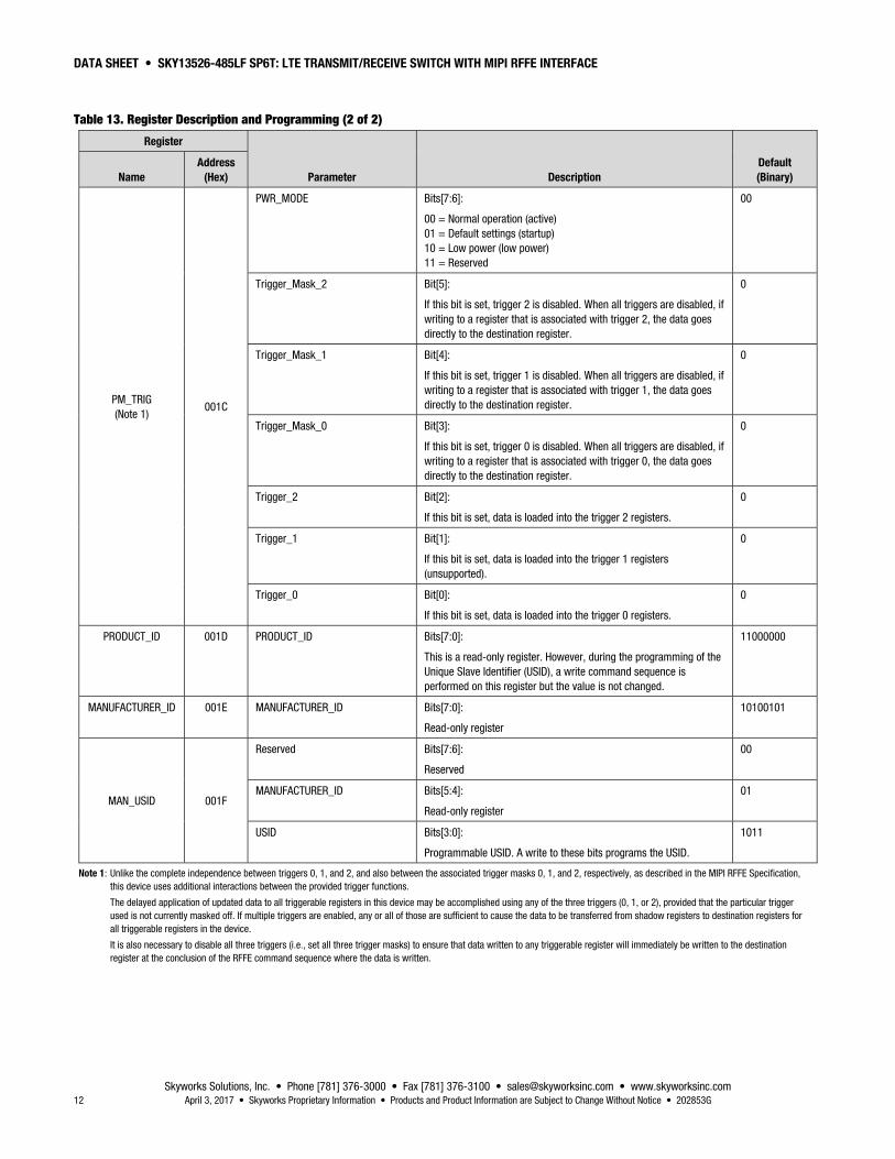
Table 13. Register Description and Programming (2 of 2)
Register
Parameter Description Default (Binary) Name
Address (Hex)
PM_TRIG (Note 1)
001C
PWR_MODE Bits[7:6]:
00 = Normal operation (active) 01 = Default settings (startup) 10 = Low power (low power) 11 = Reserved
00
Trigger_Mask_2 Bit[5]:
If this bit is set, trigger 2 is disabled. When all triggers are disabled, if writing to a register that is associated with trigger 2, the data goes directly to the destination register.
0
Trigger_Mask_1 Bit[4]:
If this bit is set, trigger 1 is disabled. When all triggers are disabled, if writing to a register that is associated with trigger 1, the data goes directly to the destination register.
0
Trigger_Mask_0 Bit[3]:
If this bit is set, trigger 0 is disabled. When all triggers are disabled, if writing to a register that is associated with trigger 0, the data goes directly to the destination register.
0
Trigger_2 Bit[2]:
If this bit is set, data is loaded into the trigger 2 registers.
0
Trigger_1 Bit[1]:
If this bit is set, data is loaded into the trigger 1 registers (unsupported).
0
Trigger_0 Bit[0]:
If this bit is set, data is loaded into the trigger 0 registers.
0
PRODUCT_ID 001D PRODUCT_ID Bits[7:0]:
This is a read-only register. However, during the programming of the Unique Slave Identifier (USID), a write command sequence is performed on this register but the value is not changed.
11000000
MANUFACTURER_ID 001E MANUFACTURER_ID Bits[7:0]:
Read-only register
10100101
MAN_USID 001F
Reserved Bits[7:6]:
Reserved
00
MANUFACTURER_ID Bits[5:4]:
Read-only register
01
USID Bits[3:0]:
Programmable USID. A write to these bits programs the USID.
1011
Note 1: Unlike the complete independence between triggers 0, 1, and 2, and also between the associated trigger masks 0, 1, and 2, respectively, as described in the MIPI RFFE Specification, this device uses additional interactions between the provided trigger functions.
The delayed application of updated data to all triggerable registers in this device may be accomplished using any of the three triggers (0, 1, or 2), provided that the particular trigger used is not currently masked off. If multiple triggers are enabled, any or all of those are sufficient to cause the data to be transferred from shadow registers to destination registers for all triggerable registers in the device.
It is also necessary to disable all three triggers (i.e., set all three trigger masks) to ensure that data written to any triggerable register will immediately be written to the destination register at the conclusion of the RFFE command sequence where the data is written.
DATA SHEET • SKY13526-485LF SP6T: LTE TRANSMIT/RECEIVE SWITCH WITH MIPI RFFE INTERFACE
Skyworks Solutions, Inc. • Phone [781] 376-3000 • Fax [781] 376-3100 • [email protected] • www.skyworksinc.com 202853G • Skyworks Proprietary Information • Products and Product Information are Subject to Change Without Notice • April 3, 2017 13
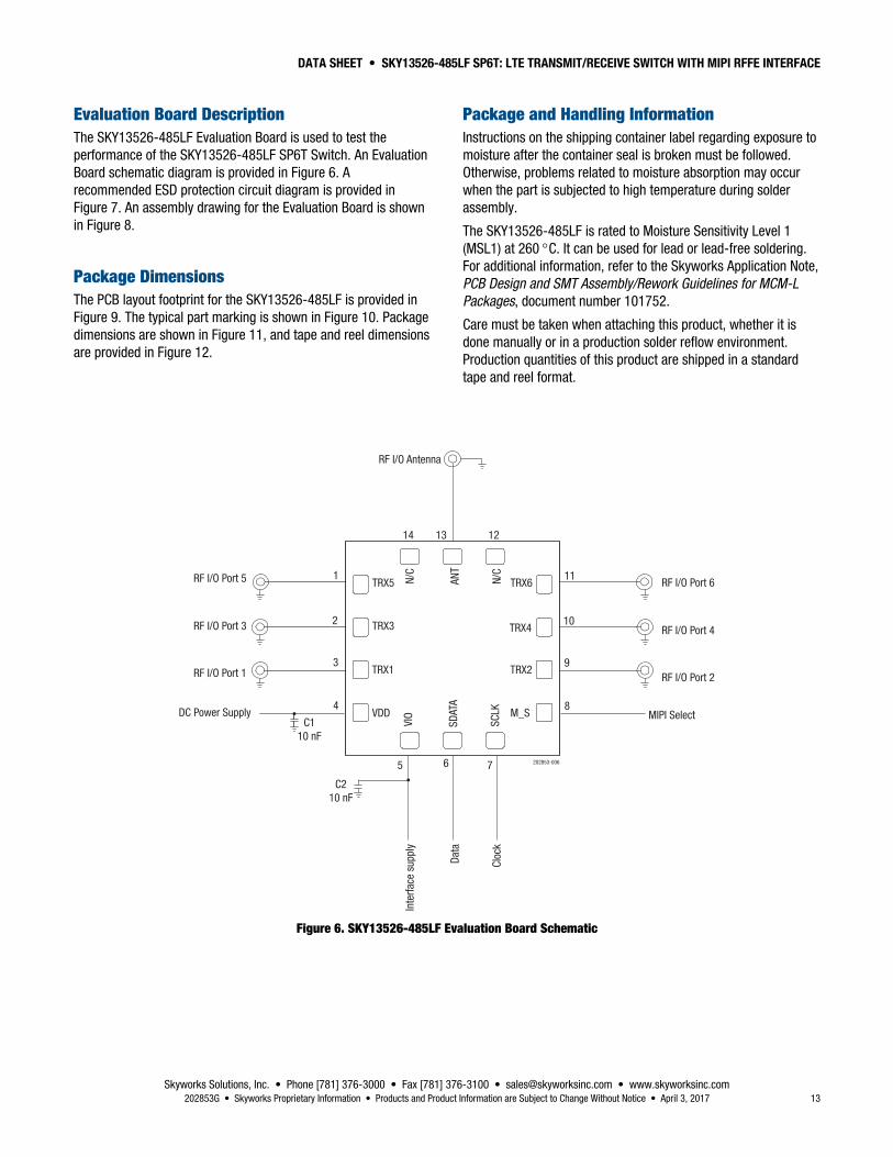
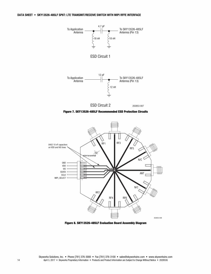
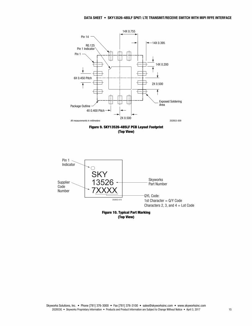
Evaluation Board Description The SKY13526-485LF Evaluation Board is used to test the performance of the SKY13526-485LF SP6T Switch. An Evaluation Board schematic diagram is provided in Figure 6. A recommended ESD protection circuit diagram is provided in Figure 7. An assembly drawing for the Evaluation Board is shown in Figure 8.
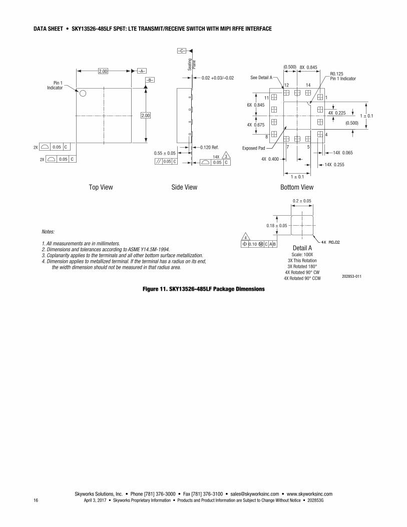
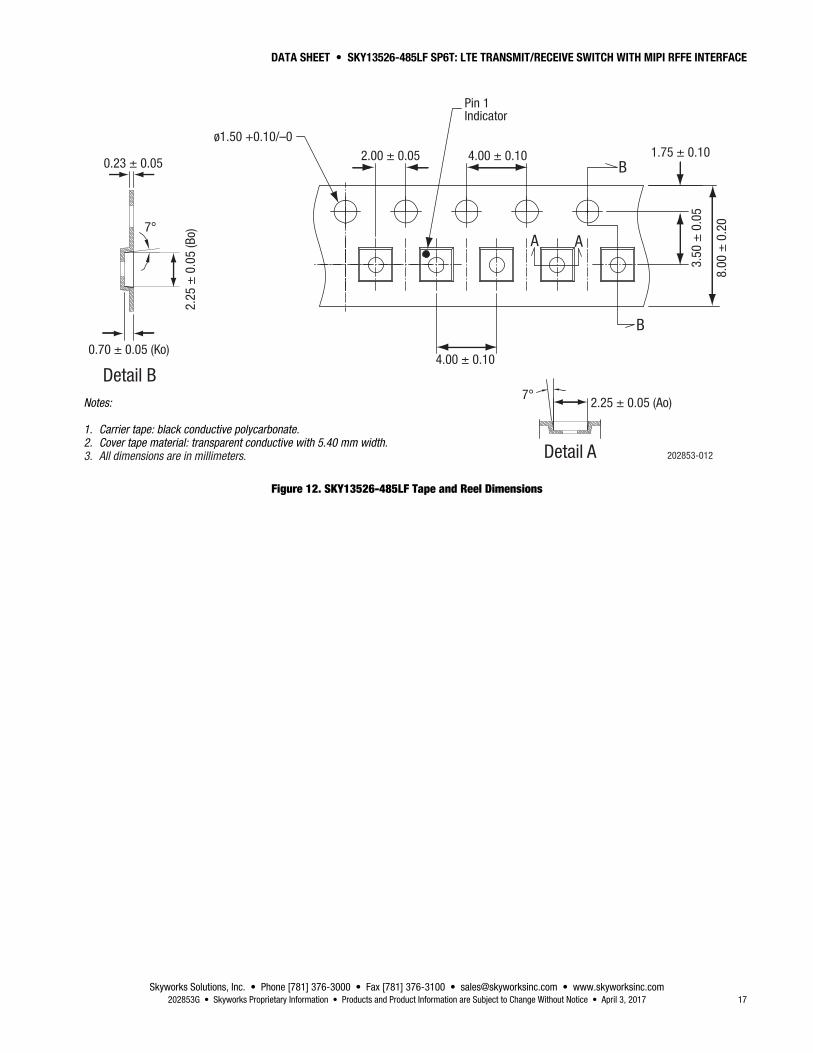
Package Dimensions The PCB layout footprint for the SKY13526-485LF is provided in Figure 9. The typical part marking is shown in Figure 10. Package dimensions are shown in Figure 11, and tape and reel dimensions are provided in Figure 12.
Package and Handling Information Instructions on the shipping container label regarding exposure to moisture after the container seal is broken must be followed. Otherwise, problems related to moisture absorption may occur when the part is subjected to high temperature during solder assembly.
The SKY13526-485LF is rated to Moisture Sensitivity Level 1 (MSL1) at 260 C. It can be used for lead or lead-free soldering. For additional information, refer to the Skyworks Application Note, PCB Design and SMT Assembly/Rework Guidelines for MCM-L Packages, document number 101752.
Care must be taken when attaching this product, whether it is done manually or in a production solder reflow environment. Production quantities of this product are shipped in a standard tape and reel format.
RF I/O Port 5
RF I/O Port 3
RF I/O Port 1
DC Power Supply
1
2
3
4
C110 nF
TRX5
TRX1
VDD
TRX6
TRX4
TRX2
M_S
VIO
SDAT
A
SCLK
N/C
ANT
N/C 11
10
9
8
5 6 7
14 13 12
RF I/O Antenna
RF I/O Port 6
RF I/O Port 4
RF I/O Port 2
MIPI Select
C210 nF
Inte
rface
sup
ply
Data
Cloc
k
TRX3
202853-006
Figure 6. SKY13526-485LF Evaluation Board Schematic
DATA SHEET • SKY13526-485LF SP6T: LTE TRANSMIT/RECEIVE SWITCH WITH MIPI RFFE INTERFACE
Skyworks Solutions, Inc. • Phone [781] 376-3000 • Fax [781] 376-3100 • [email protected] • www.skyworksinc.com 14 April 3, 2017 • Skyworks Proprietary Information • Products and Product Information are Subject to Change Without Notice • 202853G
202853-007
18 nH
4.7 pF
18 nH
To ApplicationAntenna
To ApplicationAntenna
ESD Circuit 1
ESD Circuit 2
To SKY13526-485LFAntenna (Pin 13)
To SKY13526-485LFAntenna (Pin 13)
12 pF
12 nH
Figure 7. SKY13526-485LF Recommended ESD Protection Circuits
202853-008
RF1 RF3
RF5
N/C
ANT
N/C
RF6RF4
RF2
GNDVDDVIO
SDATASCLK
MIPI_SELECT
0402 10 nF capacitors on VDD and VIO lines
Figure 8. SKY13526-485LF Evaluation Board Assembly Diagram
DATA SHEET • SKY13526-485LF SP6T: LTE TRANSMIT/RECEIVE SWITCH WITH MIPI RFFE INTERFACE
Skyworks Solutions, Inc. • Phone [781] 376-3000 • Fax [781] 376-3100 • [email protected] • www.skyworksinc.com 202853G • Skyworks Proprietary Information • Products and Product Information are Subject to Change Without Notice • April 3, 2017 15
6X 0.450 Pitch
14X 0.200
2X 0.500
2X 0.500
4X 0.400 Pitch
14X 0.755
14X 0.395
Exposed SolderingAreaPackage Outline
R0.125Pin 1 Indicator
Pin 1
Pin 14
202853-009All measurements in millimeters
Figure 9. SKY13526-485LF PCB Layout Footprint (Top View)
202853-010
Pin 1Indicator
SkyworksPart Number
QYL Code:1st Character = Q/Y CodeCharacters 2, 3, and 4 = Lot Code
SupplierCodeNumber
SKY135267XXXX
Figure 10. Typical Part Marking (Top View)
DATA SHEET • SKY13526-485LF SP6T: LTE TRANSMIT/RECEIVE SWITCH WITH MIPI RFFE INTERFACE
Skyworks Solutions, Inc. • Phone [781] 376-3000 • Fax [781] 376-3100 • [email protected] • www.skyworksinc.com 16 April 3, 2017 • Skyworks Proprietary Information • Products and Product Information are Subject to Change Without Notice • 202853G
202853-011
Top View Side View Bottom View
0.05 C
Pin 1Indicator
2X
0.05 C2X0.05 C14X 3
4
C0.05
2.00 –A–
–B–
–C–
Seat
ing
Plan
e
See Detail A
Exposed Pad
0.02 +0.03/–0.02
0.120 Ref.14X 0.065
14X 0.2554X 0.400
(0.500)
(0.500)
1
12 14
7 5
4
11
8
6X 0.845
4X 0.675
8X 0.845
0.2 ± 0.05
0.18 ± 0.05
1 ± 0.1
1 ± 0.1
4X 0.225
R0.125Pin 1 Indicator
0.55 ± 0.05
0.10 M C A BDetail AScale: 100X
3X This Rotation3X Rotated 180°
4X Rotated 90° CW4X Rotated 90° CCW
Notes:
1. All measurements are in millimeters.2. Dimensions and tolerances according to ASME Y14.5M-1994.3. Coplanarity applies to the terminals and all other bottom surface metallization.4. Dimension applies to metallized terminal. If the terminal has a radius on its end, the width dimension should not be measured in that radius area.
2.00
Figure 11. SKY13526-485LF Package Dimensions
DATA SHEET • SKY13526-485LF SP6T: LTE TRANSMIT/RECEIVE SWITCH WITH MIPI RFFE INTERFACE
Skyworks Solutions, Inc. • Phone [781] 376-3000 • Fax [781] 376-3100 • [email protected] • www.skyworksinc.com 202853G • Skyworks Proprietary Information • Products and Product Information are Subject to Change Without Notice • April 3, 2017 17
202853-012Detail A
Detail B
0.23 ± 0.05
2.25
± 0
.05
(Bo)
1.75 ± 0.10ø1.50 +0.10/–0
3.50
± 0
.05
0.70 ± 0.05 (Ko)
8.00
± 0
.20
2.25 ± 0.05 (Ao)7°
7°
4.00 ± 0.10
4.00 ± 0.10
2.00 ± 0.05
Pin 1Indicator
A
B
B
A
Notes:
1. Carrier tape: black conductive polycarbonate.2. Cover tape material: transparent conductive with 5.40 mm width.3. All dimensions are in millimeters.
Figure 12. SKY13526-485LF Tape and Reel Dimensions
DATA SHEET • SKY13526-485LF SP6T: LTE TRANSMIT/RECEIVE SWITCH WITH MIPI RFFE INTERFACE
Skyworks Solutions, Inc. • Phone [781] 376-3000 • Fax [781] 376-3100 • [email protected] • www.skyworksinc.com 18 April 3, 2017 • Skyworks Proprietary Information • Products and Product Information are Subject to Change Without Notice • 202853G
Ordering Information Model Name Manufacturing Part Number Evaluation Board Part Number
SKY13526-485LF: 0.4 to 3.8 GHz SP6T LTE Transmit/Receive Switch with MIPI RFFE Interface SKY13526-485LF SKY13526-485LF-EVB
Copyright © 2013-2017 Skyworks Solutions, Inc. All Rights Reserved.
Information in this document is provided in connection with Skyworks Solutions, Inc. (“Skyworks”) products or services. These materials, including the information contained herein, are provided by Skyworks as a service to its customers and may be used for informational purposes only by the customer. Skyworks assumes no responsibility for errors or omissions in these materials or the information contained herein. Skyworks may change its documentation, products, services, specifications or product descriptions at any time, without notice. Skyworks makes no commitment to update the materials or information and shall have no responsibility whatsoever for conflicts, incompatibilities, or other difficulties arising from any future changes.
No license, whether express, implied, by estoppel or otherwise, is granted to any intellectual property rights by this document. Skyworks assumes no liability for any materials, products or information provided hereunder, including the sale, distribution, reproduction or use of Skyworks products, information or materials, except as may be provided in Skyworks Terms and Conditions of Sale.
THE MATERIALS, PRODUCTS AND INFORMATION ARE PROVIDED “AS IS” WITHOUT WARRANTY OF ANY KIND, WHETHER EXPRESS, IMPLIED, STATUTORY, OR OTHERWISE, INCLUDING FITNESS FOR A PARTICULAR PURPOSE OR USE, MERCHANTABILITY, PERFORMANCE, QUALITY OR NON-INFRINGEMENT OF ANY INTELLECTUAL PROPERTY RIGHT; ALL SUCH WARRANTIES ARE HEREBY EXPRESSLY DISCLAIMED. SKYWORKS DOES NOT WARRANT THE ACCURACY OR COMPLETENESS OF THE INFORMATION, TEXT, GRAPHICS OR OTHER ITEMS CONTAINED WITHIN THESE MATERIALS. SKYWORKS SHALL NOT BE LIABLE FOR ANY DAMAGES, INCLUDING BUT NOT LIMITED TO ANY SPECIAL, INDIRECT, INCIDENTAL, STATUTORY, OR CONSEQUENTIAL DAMAGES, INCLUDING WITHOUT LIMITATION, LOST REVENUES OR LOST PROFITS THAT MAY RESULT FROM THE USE OF THE MATERIALS OR INFORMATION, WHETHER OR NOT THE RECIPIENT OF MATERIALS HAS BEEN ADVISED OF THE POSSIBILITY OF SUCH DAMAGE.
Skyworks products are not intended for use in medical, lifesaving or life-sustaining applications, or other equipment in which the failure of the Skyworks products could lead to personal injury, death, physical or environmental damage. Skyworks customers using or selling Skyworks products for use in such applications do so at their own risk and agree to fully indemnify Skyworks for any damages resulting from such improper use or sale.
Customers are responsible for their products and applications using Skyworks products, which may deviate from published specifications as a result of design defects, errors, or operation of products outside of published parameters or design specifications. Customers should include design and operating safeguards to minimize these and other risks. Skyworks assumes no liability for applications assistance, customer product design, or damage to any equipment resulting from the use of Skyworks products outside of stated published specifications or parameters.
Skyworks and the Skyworks symbol are trademarks or registered trademarks of Skyworks Solutions, Inc., in the United States and other countries. Third-party brands and names are for identification purposes only, and are the property of their respective owners. Additional information, including relevant terms and conditions, posted at www.skyworksinc.com, are incorporated by reference.


![DATA SHEET SKY13416-485LF: 0.1 to 3.8 GHz SP6T Antenna …€¦ · DATA SHEET • SKY13416-485LF: SP6T ANTENNA SWITCH Skyworks Solutions, Inc. • Phone [781] 376-3000 • Fax [781]](https://img.pdfslide.us/doc/110x75/5b9cf6e709d3f2de128b5149/data-sheet-sky13416-485lf-01-to-38-ghz-sp6t-antenna-data-sheet-sky13416-485lf.jpg)