Embed Size (px)
Citation preview
1
INDIAN INSTITUTE OF TECHNOLOGY KANPUR
UNDER GRADUATE PROJECT
DESIGN AND IMPLEMENTATION OF TRANSMITTER CHAIN FOR MACHINE TYPE
COMMUNICATION ON LTE NETWORKS
Submitted by -
Hemanth Bollamreddi
Department of Electrical Engineering
Indian Institute of Technology, Kanpur
Email: [email protected]
Supervised by -
Dr. Rohit Budhiraja
Department of Electrical Engineering
Indian Institute of Technology, Kanpur
Email: [email protected]
2
TABLE OF CONTENTS
1. ACKNOLWEDGEMENT
2. ABSTRACT
3. INTRODUCTION
• LTE
• LTE PROTOCOL STACK
• OFDM MODULATION
• LTE BANDWIDTHS
• LTE PHYSICAL RESOURCES
• LTE RESOURCE MAPPING
4. MTC & 3GPP STANDARDS
• MTC - GENERAL CHARACTERISTICS
• OPERATION IN 1.4MHz
• DOWNLINK TRANSMISSION
• COVERAGE ENHANCMENT
• TYPE B HALF DUPLEX
• POWER SAVING MODE
5. DESIGN AND PROTOTYPING
• SOFTWARES
• HARDWARE
• IMPLEMENTATION
• MPDCCH ENCODING
• PDCCH ENCODING
• PDSCH ENCODING
• TX I/Q PROCESSING
6. ARCHITECTURE IMPLEMENTED
7. FINAL IMPLEMENTATION AND DEMONSTRATION
8. REFERENCES
9. INDEX OF FIGURES
3
ACKNOWLEDGEMENTS
I am highly grateful to my project supervisor, Dr. Rohit Budhiraja for consenting
to mentor me and providing his valuable guidance, constant support and
encouragement throughout the semester and for motivating to continue the
project work. I am thankful to him for all the efforts he has taken up to help me
develop my writing and presentation skills.
I would also like to thank Mr. Brijendra Kumar, the lab in-charge for providing us
his expertise and making me acquainted with the hardware. Special thanks to
Vishad Viplav and Ashutosh Srivastava who helped me in designing and testing
the code.
4
ABSTRACT
The LTE technology has become most popular recently due to the high data
rates, high capacity and spectrum efficiency. LTE is being continuously
developed so as to include newer and innovative applications. Release 12 and
13 of LTE has specified Machine type communication using LTE. Unlike normal
LTE usage, MTC requires very less data-rates. Data rates of 1Mbps has been
specified in release 13 of LTE.
Machine Type Communication is generally characterized by communication
between large number of devices with less or no human interaction. On a broad
scale, MTC can be divided into massive-MTC and critical-MTC. In massive MTC,
large number of devices are connected together and the difficulty lie in
connecting remote devices. Radio technology supporting massive-MTC
applications must therefore be able to operate properly with very high path loss
between base stations and devices.
Critical-MTC are often associated with requirements on extremely high
reliability and extremely high availability within the area where the application
is to be supported. Many of these applications also have requirements on very
low and predictable latency.
The main advantage of MTC using LTE is mobility. Presently, the radio access
architecture for MTC is of short-range. Using LTE for MTC can be advantageous
for devices requiring data transfer from distant devices/servers.
This project involves design, implementation and then demonstration of
transmitter chain for LTE system capable of Machine Type Communication. The
system would be based on version 13 LTE standards by 3GPP and built on an
existing framework of version 8 LTE. Implementation and demonstration would
be done on a Software Defined Radio from National Instruments.
5
INTRODUCTION
LTE:
LTE is a standard for high-speed wireless communication for mobile devices and
data-terminals that is developed by 3GPP and specified in its release 8 and 9. It
is also referred to as 4G LTE. Later releases provided various enhancements
(Multi Antenna Support, Network Densification etc.).
Release 13 (early 2015) included enhancements in machine type communication
(MTC).
LTE PROTOCOL STACK:
LTE protocol stack shows various layers of implementing the LTE and the flow of
data.
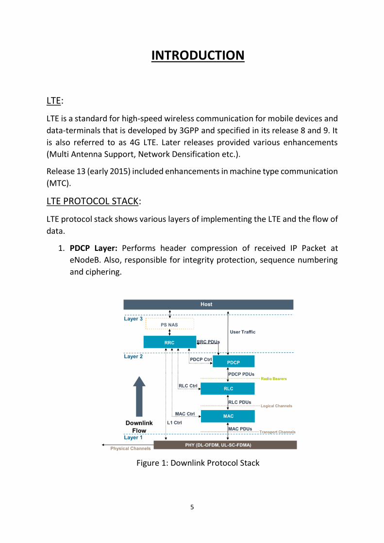
1. PDCP Layer: Performs header compression of received IP Packet at
eNodeB. Also, responsible for integrity protection, sequence numbering
and ciphering.
Figure 1: Downlink Protocol Stack
6
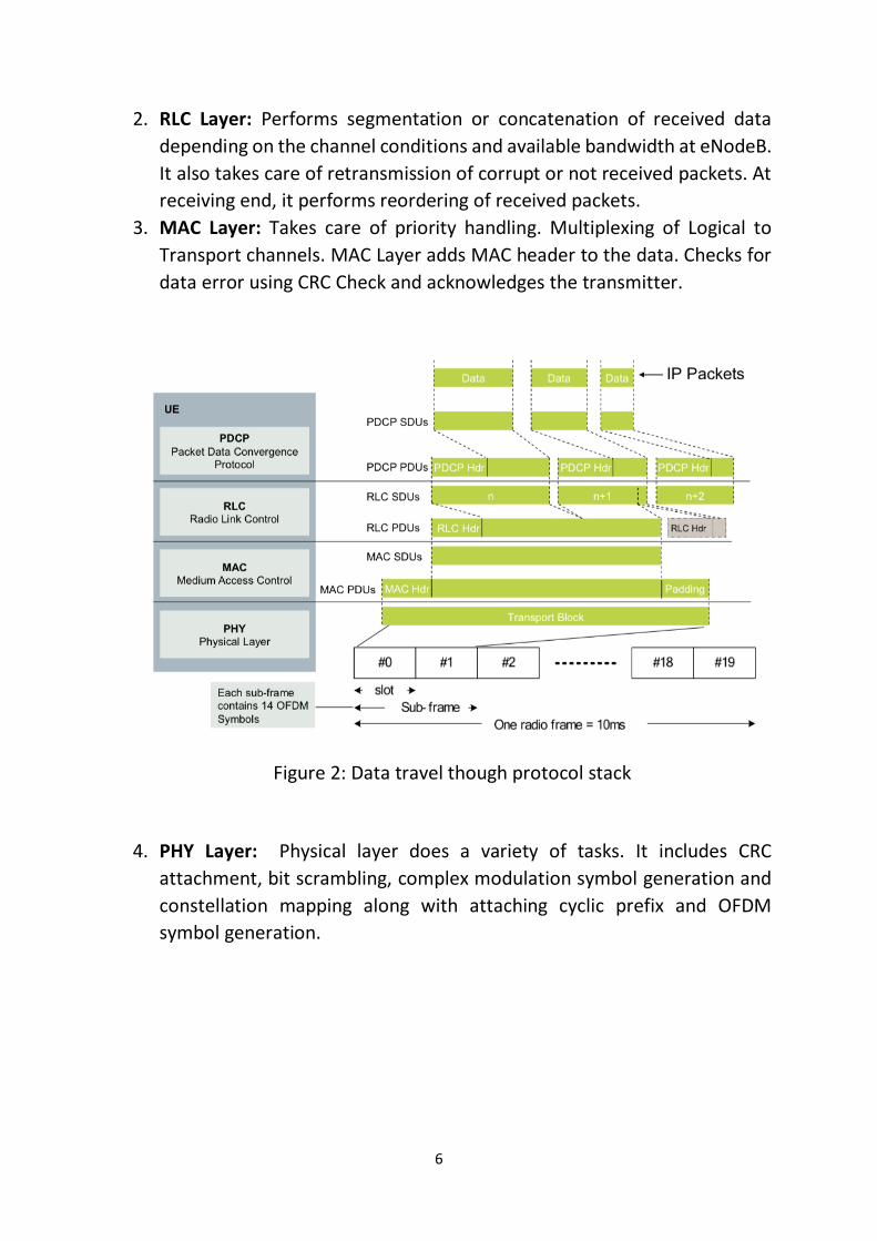
2. RLC Layer: Performs segmentation or concatenation of received data
depending on the channel conditions and available bandwidth at eNodeB.
It also takes care of retransmission of corrupt or not received packets. At
receiving end, it performs reordering of received packets.
3. MAC Layer: Takes care of priority handling. Multiplexing of Logical to
Transport channels. MAC Layer adds MAC header to the data. Checks for
data error using CRC Check and acknowledges the transmitter.
Figure 2: Data travel though protocol stack
4. PHY Layer: Physical layer does a variety of tasks. It includes CRC
attachment, bit scrambling, complex modulation symbol generation and
constellation mapping along with attaching cyclic prefix and OFDM
symbol generation.
7
OFDM MODULATION:
In OFDM (Orthogonal Frequency Division Multiplexing) Modulation, given
bandwidth consists of subcarriers spaced at 15KHz. Data is put on each sub-
carrier and transmitted simultaneously. There will not be any interference due
to orthogonality of the sinc signals in frequency domain. Advantages include
Increased spectrum efficiency and resistance to frequency selective fading (due
to long symbol time) and inter-symbol interference. LTE downlink uses OFDMA
Modulation while uplink uses a modified OFDM called SC-FDMA.
LTE BANDWIDTHS:
LTE supports a handful of bandwidths. They are 1.4MHz, 3Mhz, 5MHz, 10MHz,
15MHz, 20MHz. The normal working of LTE is generally in 10 or 20MHz.
MTC devices work in 1.4MHz bandwidth because less amount of data rate is
required. These devices are often called (Narrow Band) NB-IoT devices.
LTE PHYSICAL RESOURCES:
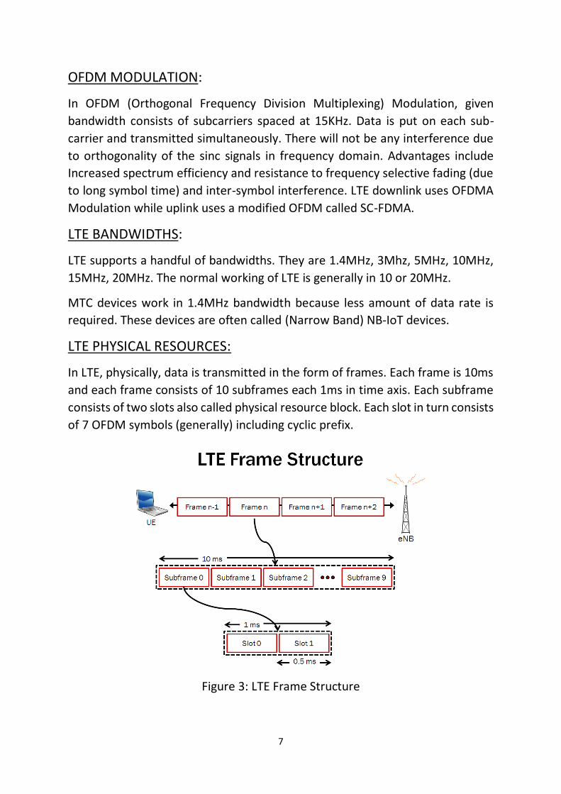
In LTE, physically, data is transmitted in the form of frames. Each frame is 10ms
and each frame consists of 10 subframes each 1ms in time axis. Each subframe
consists of two slots also called physical resource block. Each slot in turn consists
of 7 OFDM symbols (generally) including cyclic prefix.
Figure 3: LTE Frame Structure
8
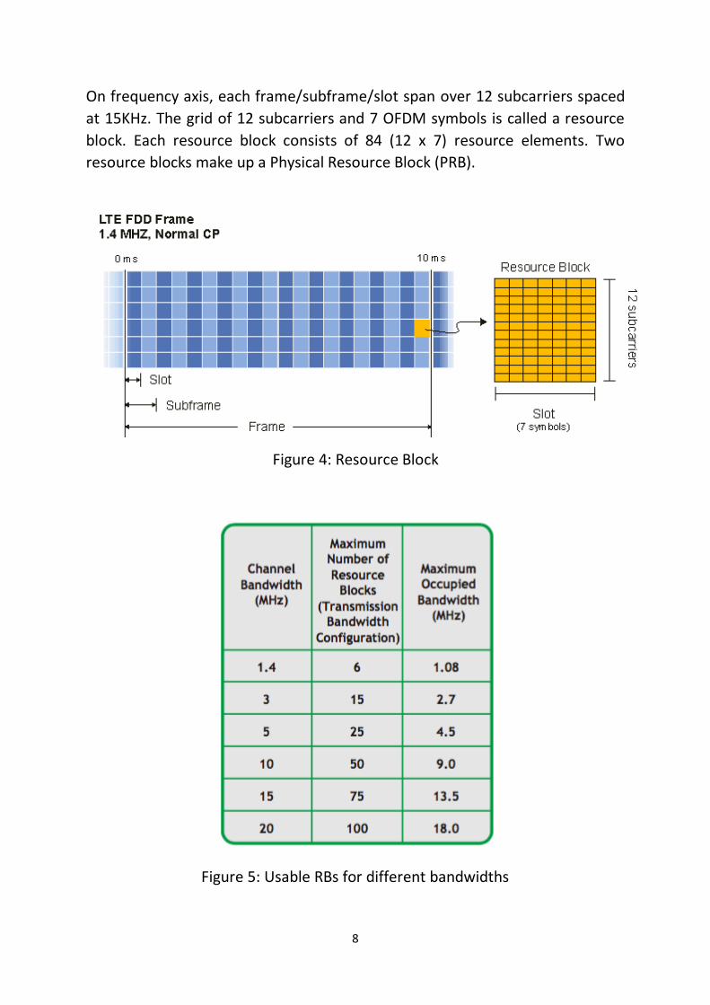
On frequency axis, each frame/subframe/slot span over 12 subcarriers spaced
at 15KHz. The grid of 12 subcarriers and 7 OFDM symbols is called a resource
block. Each resource block consists of 84 (12 x 7) resource elements. Two
resource blocks make up a Physical Resource Block (PRB).
Figure 4: Resource Block
Figure 5: Usable RBs for different bandwidths
9
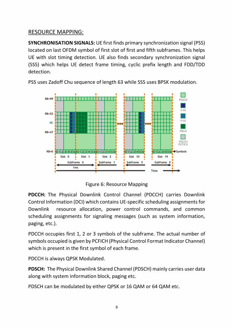
RESOURCE MAPPING:
SYNCHRONISATION SIGNALS: UE first finds primary synchronization signal (PSS)
located on last OFDM symbol of first slot of first and fifth subframes. This helps
UE with slot timing detection. UE also finds secondary synchronization signal
(SSS) which helps UE detect frame timing, cyclic prefix length and FDD/TDD
detection.
PSS uses Zadoff Chu sequence of length 63 while SSS uses BPSK modulation.
Figure 6: Resource Mapping
PDCCH: The Physical Downlink Control Channel (PDCCH) carries Downlink
Control Information (DCI) which contains UE-specific scheduling assignments for
Downlink resource allocation, power control commands, and common
scheduling assignments for signaling messages (such as system information,
paging, etc.).
PDCCH occupies first 1, 2 or 3 symbols of the subframe. The actual number of
symbols occupied is given by PCFICH (Physical Control Format Indicator Channel)
which is present in the first symbol of each frame.
PDCCH is always QPSK Modulated.
PDSCH: The Physical Downlink Shared Channel (PDSCH) mainly carries user data
along with system information block, paging etc.
PDSCH can be modulated by either QPSK or 16 QAM or 64 QAM etc.
10
MTC & 3GPP STANDARDS
MTC - GENERAL CHARACTERISTICS:
1. Communication that involves little or no human interaction.
2. Involves large number of devices.
3. Periodic or intermittent network access.
4. Small amount of data per session.
OPERATION IN 1.4MHz:
General LTE devices work in 20MHz bandwidth but as specified above, MTC
requires small amount of data only. Hence a bandwidth of 1.4MHz is specified
standard (LTE Cat-M1). The peak downlink and uplink data rate for this
bandwidth is 1Mbps. At a given time, a MTC device can send or receive on a
single narrowband (6 RBs). Thus, physical channels which inherently span over
wideband cannot be received by MTC.
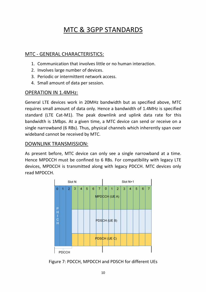
DOWNLINK TRANSMISSION:
As present before, MTC device can only see a single narrowband at a time.
Hence MPDCCH must be confined to 6 RBs. For compatibility with legacy LTE
devices, MPDCCH is transmitted along with legacy PDCCH. MTC devices only
read MPDCCH.
Figure 7: PDCCH, MPDCCH and PDSCH for different UEs

11
12
MPDCCH is transmitted in Resource Elements which otherwise was occupied
by PDSCH. In first few sub frames, PDCCH along with MPDCCH is transmitted.
In these subframes PDSCH is not transmitted. In the last subframes, P DCCH
and PDSCH is transmitted.
DCI format 6 is used for MPDCCH. This DCI contains information about narrow-
band indicator, resource block indicator, PDSCH repetition mode, MPDCCH
repetition mode, modulation scheme, HARQ process number, power control,
DCI format fag, Frequency hopping flag.
COVERAGE ENHANCEMENT:
Coverage enhancement is important part of MTC for supporting remote devices.
Coverage enhancement as explained below is done at the cost of data-rate.
Coverage enhancement is done by repetitions. A subframe is replicated and
send multiple times in consecutive subframes.
Figure 8: MPDCCH and PDSCH Repetitions
There are two modes of repetitions CE Mode A and CE Mode B where Mode B
offers extensive coverage. Decoding parameters for PDSCH is extracted from last
repeated set of MPDCCH sub-frames.
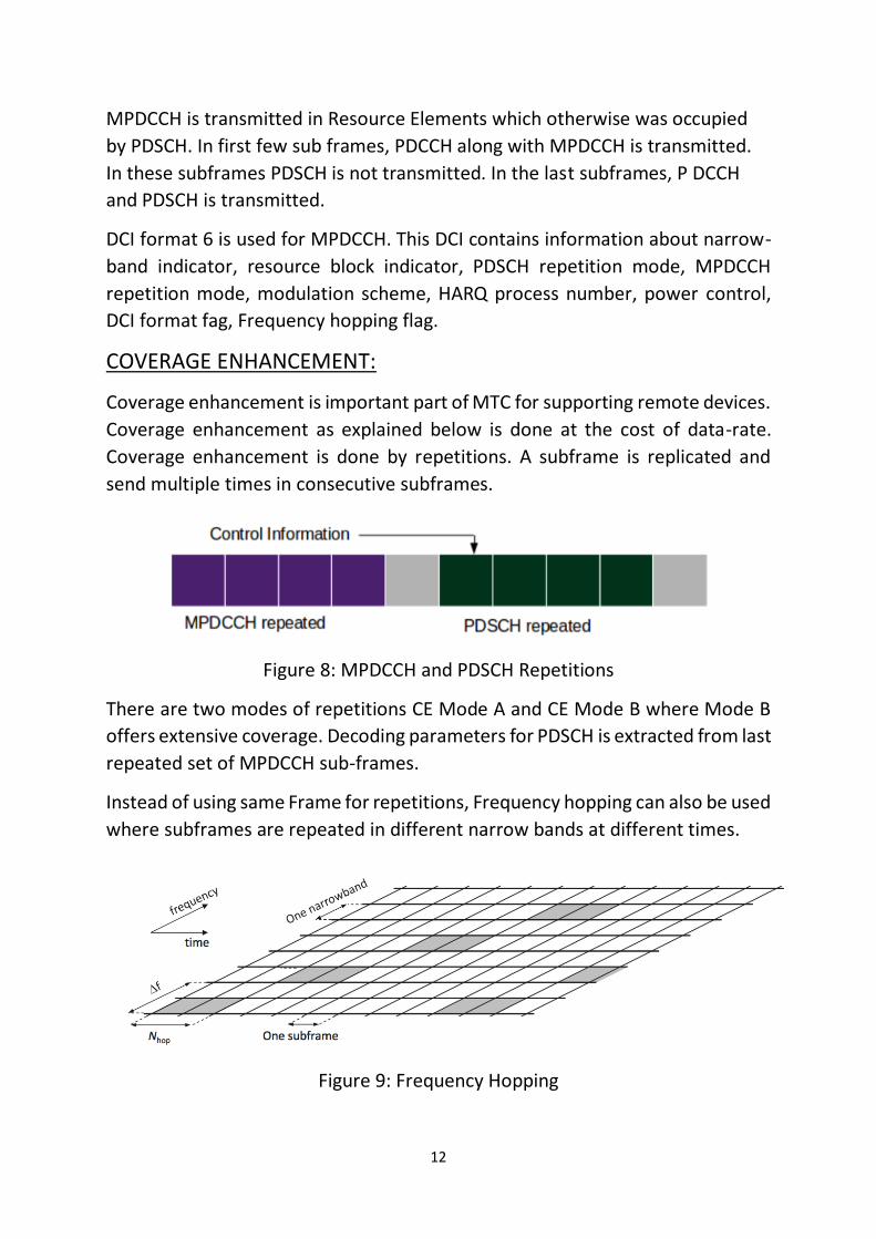
Instead of using same Frame for repetitions, Frequency hopping can also be used
where subframes are repeated in different narrow bands at different times.
Figure 9: Frequency Hopping
13
TYPE-B HALF DUPLEX OPERATION:
In half duplex operation, data cannot be transmitted and received at same time.
It is done at different times (different subframes in our case). This type of
communication reduces device complexity and cost. In Type-B, the time gap
between reception and transmission is increased. This given enough time for
MTC device to process and switch.
POWER SAVING:
As given in the characteristics, MTC devices does not send data continuously.
For many devices, there are specific sampling times and data output rates. In
Power saving mode, the device although connected to the network, remains idle
without any RF activity. This type of mod prevents the need of reconnecting to
the network after the device wakes up.
14
DESIGN AND PROTOTYPING
SOFTWARES:
• LabVIEW Communication System Design Suite 2017: The software offers
a design environment closely integrated with NI SDR for rapid prototyping
of communication systems.
• LabVIEW LTE Application Framework 2.0.1: The LTE Application
Framework provides a ready to run, real-time physical layer (PHY) and
lower medium access control (MAC)-layer reference design based on the
LTE wireless standard.
HARDWARE:
• NI USRP RIO 2952 R: Software Defined Radio Reconfigurable Devices are
built on the reconfigurable I/O (RIO) and universal software radio
peripheral (USRP) architectures. They include a powerful FPGA for
advanced DSP and include 2x2 MIMO transceivers or four-channel super
heterodyne receivers, supporting center frequencies from 400 MHz to 4.4
GHz, with up to 120 MHz of instantaneous bandwidth.
15
IMPLEMENTATION:
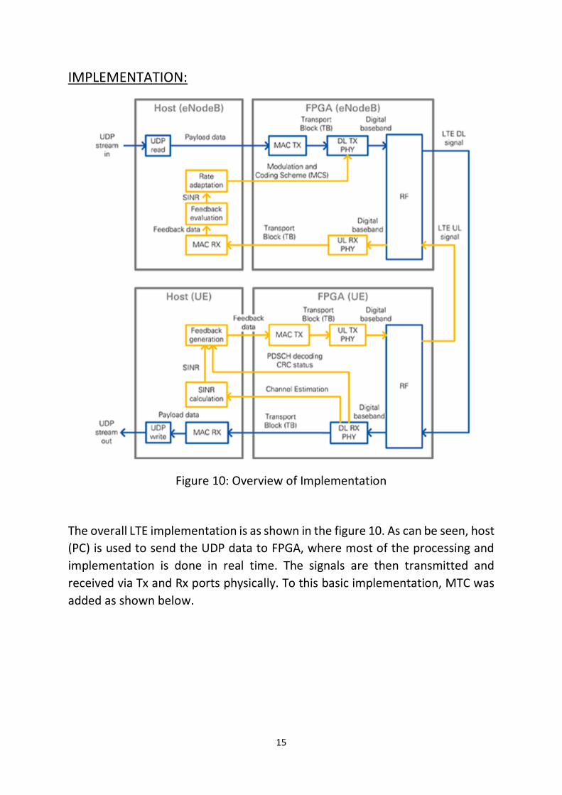
Figure 10: Overview of Implementation
The overall LTE implementation is as shown in the figure 10. As can be seen, host
(PC) is used to send the UDP data to FPGA, where most of the processing and
implementation is done in real time. The signals are then transmitted and
received via Tx and Rx ports physically. To this basic implementation, MTC was
added as shown below.
16
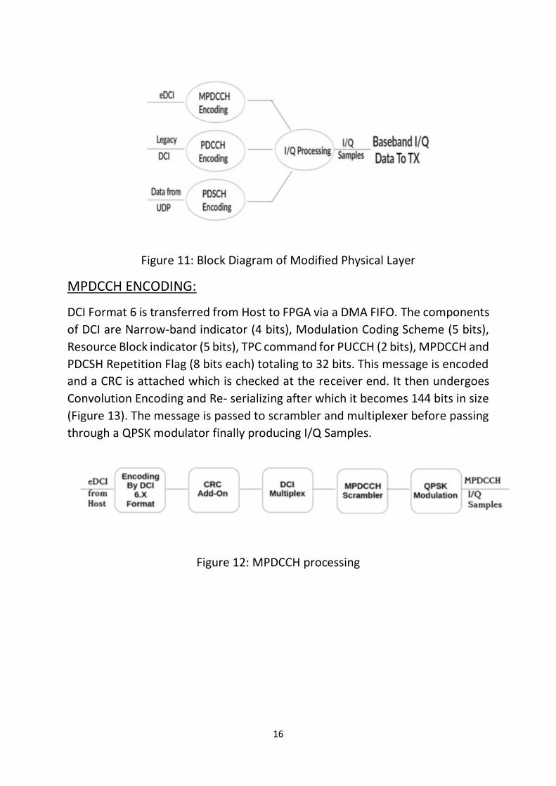
Figure 11: Block Diagram of Modified Physical Layer
MPDCCH ENCODING:
DCI Format 6 is transferred from Host to FPGA via a DMA FIFO. The components
of DCI are Narrow-band indicator (4 bits), Modulation Coding Scheme (5 bits),
Resource Block indicator (5 bits), TPC command for PUCCH (2 bits), MPDCCH and
PDCSH Repetition Flag (8 bits each) totaling to 32 bits. This message is encoded
and a CRC is attached which is checked at the receiver end. It then undergoes
Convolution Encoding and Re- serializing after which it becomes 144 bits in size
(Figure 13). The message is passed to scrambler and multiplexer before passing
through a QPSK modulator finally producing I/Q Samples.
Figure 12: MPDCCH processing
17
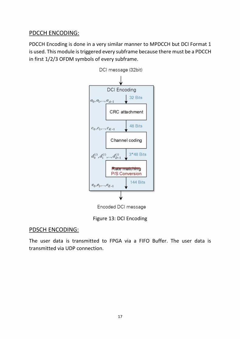
PDCCH ENCODING:
PDCCH Encoding is done in a very similar manner to MPDCCH but DCI Format 1
is used. This module is triggered every subframe because there must be a PDCCH
in first 1/2/3 OFDM symbols of every subframe.
Figure 13: DCI Encoding
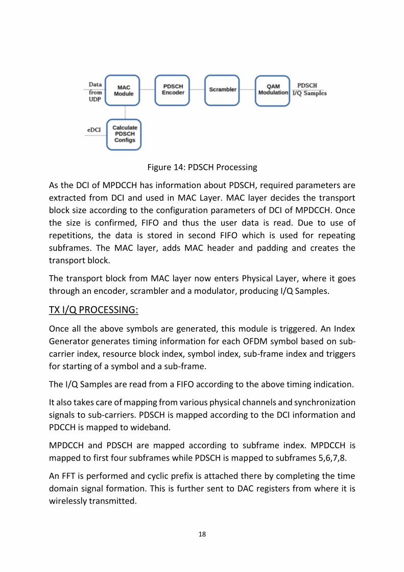
PDSCH ENCODING:
The user data is transmitted to FPGA via a FIFO Buffer. The user data is
transmitted via UDP connection.
18
Figure 14: PDSCH Processing
As the DCI of MPDCCH has information about PDSCH, required parameters are
extracted from DCI and used in MAC Layer. MAC layer decides the transport
block size according to the configuration parameters of DCI of MPDCCH. Once
the size is confirmed, FIFO and thus the user data is read. Due to use of
repetitions, the data is stored in second FIFO which is used for repeating
subframes. The MAC layer, adds MAC header and padding and creates the
transport block.
The transport block from MAC layer now enters Physical Layer, where it goes
through an encoder, scrambler and a modulator, producing I/Q Samples.
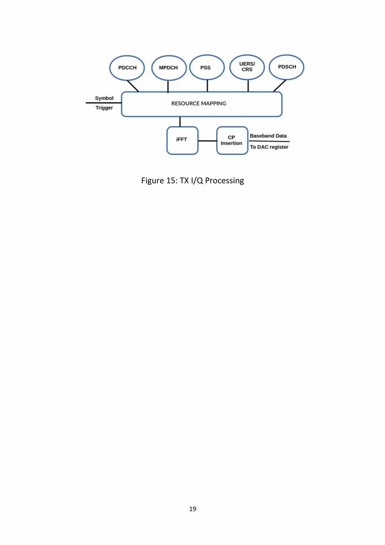
TX I/Q PROCESSING:
Once all the above symbols are generated, this module is triggered. An Index
Generator generates timing information for each OFDM symbol based on sub-
carrier index, resource block index, symbol index, sub-frame index and triggers
for starting of a symbol and a sub-frame.
The I/Q Samples are read from a FIFO according to the above timing indication.
It also takes care of mapping from various physical channels and synchronization
signals to sub-carriers. PDSCH is mapped according to the DCI information and
PDCCH is mapped to wideband.
MPDCCH and PDSCH are mapped according to subframe index. MPDCCH is
mapped to first four subframes while PDSCH is mapped to subframes 5,6,7,8.
An FFT is performed and cyclic prefix is attached there by completing the time
domain signal formation. This is further sent to DAC registers from where it is
wirelessly transmitted.
19
Figure 15: TX I/Q Processing
20
WORK DONE AND ARCHITECTURE IMPLEMETED
• UDP:
Implemented interface between host and FPGA via FIFO for taking UDP Data
and passing it as PDSCH.
• TIMINGS:
Solved certain timing errors and timeout errors.
21
FINAL IMPLEMENTATION AND DEMONSTRATION
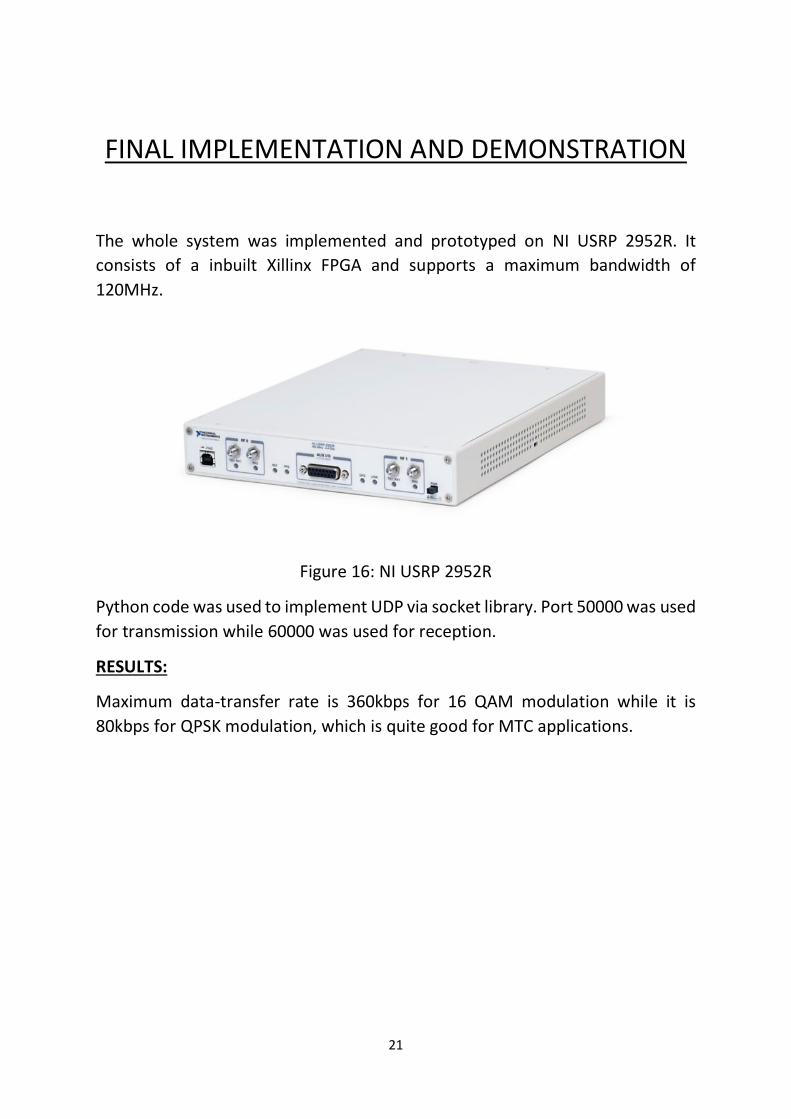
The whole system was implemented and prototyped on NI USRP 2952R. It
consists of a inbuilt Xillinx FPGA and supports a maximum bandwidth of
120MHz.
Figure 16: NI USRP 2952R
Python code was used to implement UDP via socket library. Port 50000 was used
for transmission while 60000 was used for reception.
RESULTS:
Maximum data-transfer rate is 360kbps for 16 QAM modulation while it is
80kbps for QPSK modulation, which is quite good for MTC applications.
22
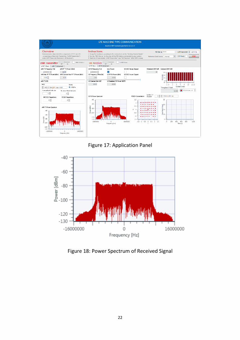
Figure 17: Application Panel
Figure 18: Power Spectrum of Received Signal
23
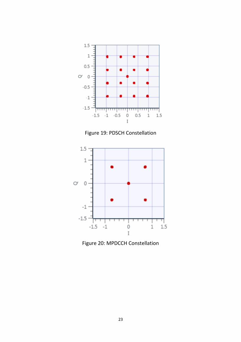
Figure 19: PDSCH Constellation
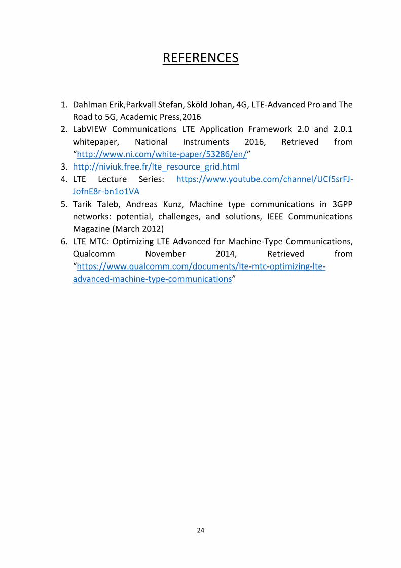
Figure 20: MPDCCH Constellation
24
REFERENCES
1. Dahlman Erik,Parkvall Stefan, Sköld Johan, 4G, LTE-Advanced Pro and The
Road to 5G, Academic Press,2016
2. LabVIEW Communications LTE Application Framework 2.0 and 2.0.1
whitepaper, National Instruments 2016, Retrieved from
“http://www.ni.com/white-paper/53286/en/”
3. http://niviuk.free.fr/lte_resource_grid.html
4. LTE Lecture Series: https://www.youtube.com/channel/UCf5srFJ-
JofnE8r-bn1o1VA
5. Tarik Taleb, Andreas Kunz, Machine type communications in 3GPP
networks: potential, challenges, and solutions, IEEE Communications
Magazine (March 2012)
6. LTE MTC: Optimizing LTE Advanced for Machine-Type Communications,
Qualcomm November 2014, Retrieved from
“https://www.qualcomm.com/documents/lte-mtc-optimizing-lte-
advanced-machine-type-communications”
25
INDEX OF FIGURES
Figure 1: Downlink Protocol Stack
Figure 2: Data travel though protocol stack
Figure 3: LTE Frame Structure
Figure 4: Resource Block
Figure 5: Usable RBs for different bandwidths
Figure 6: Resource Mapping
Figure 7: PDCCH, MPDCCH and PDSCH for different UEs
Figure 8: MPDCCH and PDSCH Repetitions
Figure 9: Frequency Hopping
Figure 10: Overview of Implementation
Figure 11: Block Diagram of Modified Physical Layer
Figure 12: MPDCCH processing
Figure 13: DCI Encoding
Figure 14: PDSCH Processing
Figure 15: TX I/Q Processing
Figure 16: NI USRP 2952R
Figure 17: Application Panel
Figure 18: Power Spectrum of Received Signal
Figure 19: PDSCH Constellation
Figure 20: MPDCCH Constellation

26