Embed Size (px)
Citation preview
Where to buy > Product page >
Data Sheet
Optimux-45, Optimux-45L Multiplexers for 21E1/28T1 over Fiber or T3
• Up to 28 T1 or 21 E1 channels multiplexed into a single 45 Mbps data stream
• Combination of T1 and E1 channels
• Transmission over coax or fiber optic cable
• Range up to 110 km (68 miles)
• Ring and chain configurations (Optimux-45 only)
The Optimux-45 and Optimux-45L fiber optic multiplexers provide a simple, flexible and cost-effective solution for transporting multiple E1 and T1 signals at distances of up to 110 km (68 miles).
The multiplexers integrate up to 21 E1, 28 T1 or combination of E1 and T1 channels, over a single 45 Mbps data stream.
This provides an easily configurable solution, flexible enough to meet the specific requirements of a broad range of applications.
Each of the E1/T1 channels is independent and can use a different clock.
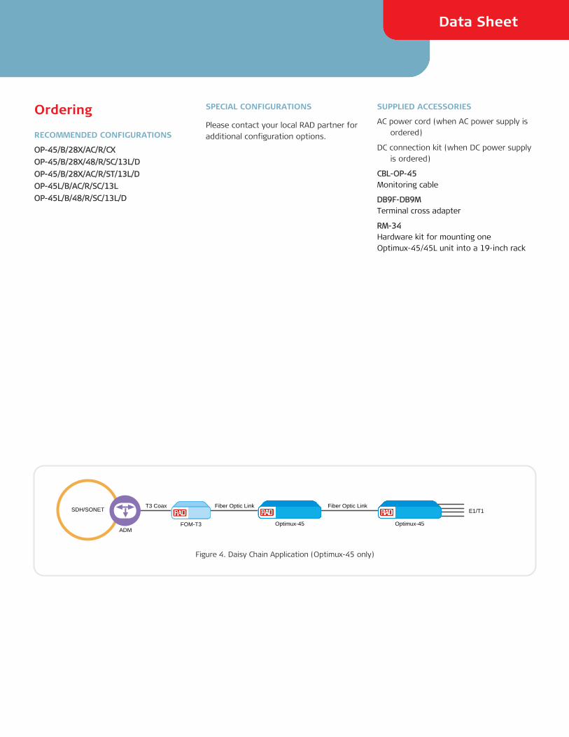
The units are interoperable with RAD’s FOM-T3 devices.
Optimux-45 and Optimux-45L conform to ITU G.703, G.747, G.823, G.824, ANSI T1.107, T1.404, RFC3895, RFC3896 standards.
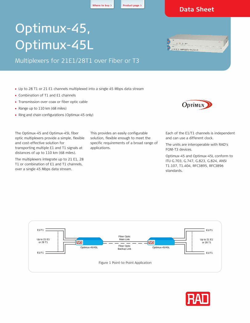
E1/T1
E1/T1
Up to 21 E1 or 28 T1
E1/T1
E1/T1
Up to 21 E1 or 28 T1
Fiber OpticMain Link
Fiber OpticBackup LinkOptimux-45/45L Optimux-45/45L
Figure 1 Point-to-Point Application
Optimux-45, Optimux-45L
Multiplexers for 21E1/28T1 over Fiber or T3
TECHNOLOGY
Two Optimux-45/45L units can be connected using WDM (Wavelength Division Multiplexing) or bidirectional technology over a single fiber (SF) link, thus reducing fiber cable costs by 50%.
The following optical interfaces are available for the fiber main link:
• 850 nm VCSEL for multimode fiber
• 1310 nm LED for multimode fiber
• 1310 and 1550 nm laser for extended range over single mode fiber
• 1310 and 1550 nm laser for single fiber WDM operation
• 1310 nm laser for single fiber/single wavelength operation.
ARCHITECTURE
Optimux-45 and Optimux-45L are available with either balanced or unbalanced tributary ports.
Optimux-45 is available with 4, 8, 12, or 28 RJ-45 connectors or with 21 mini-BNC connectors.
Optimux-45L is provided with two 64-pin Telco connectors for balanced or unbalanced tributary ports.
APPLICATIONS (OPTIMUX-45 ONLY)
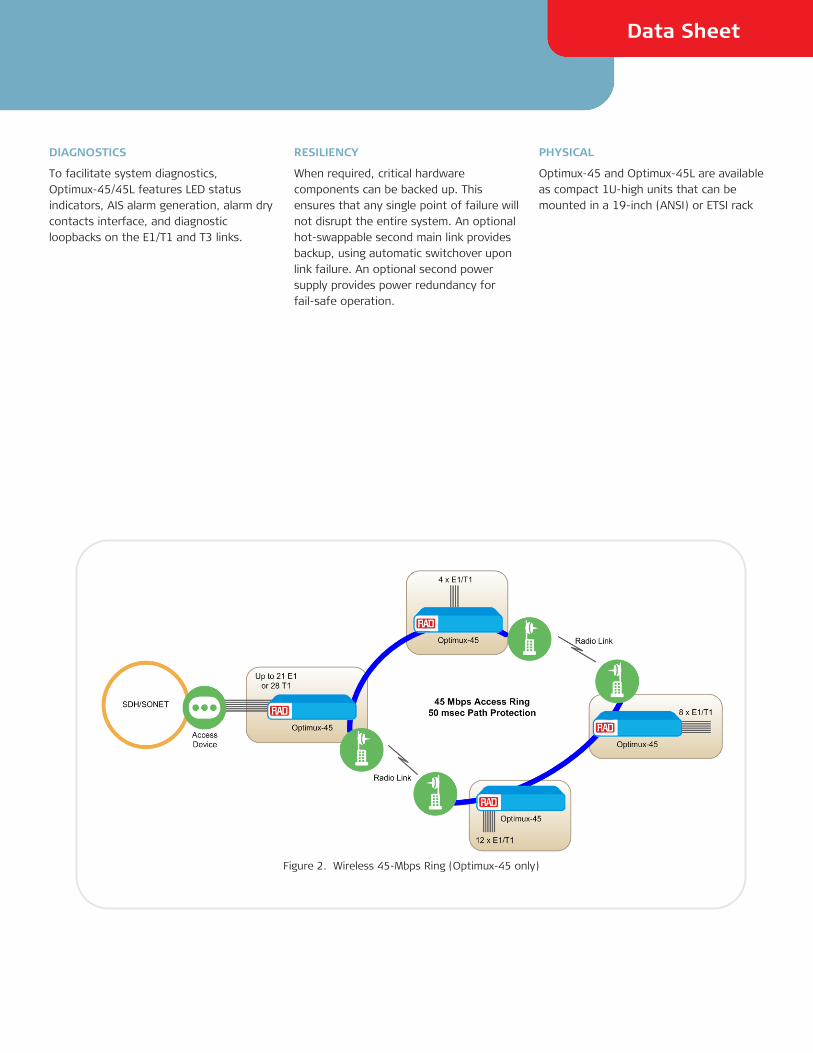
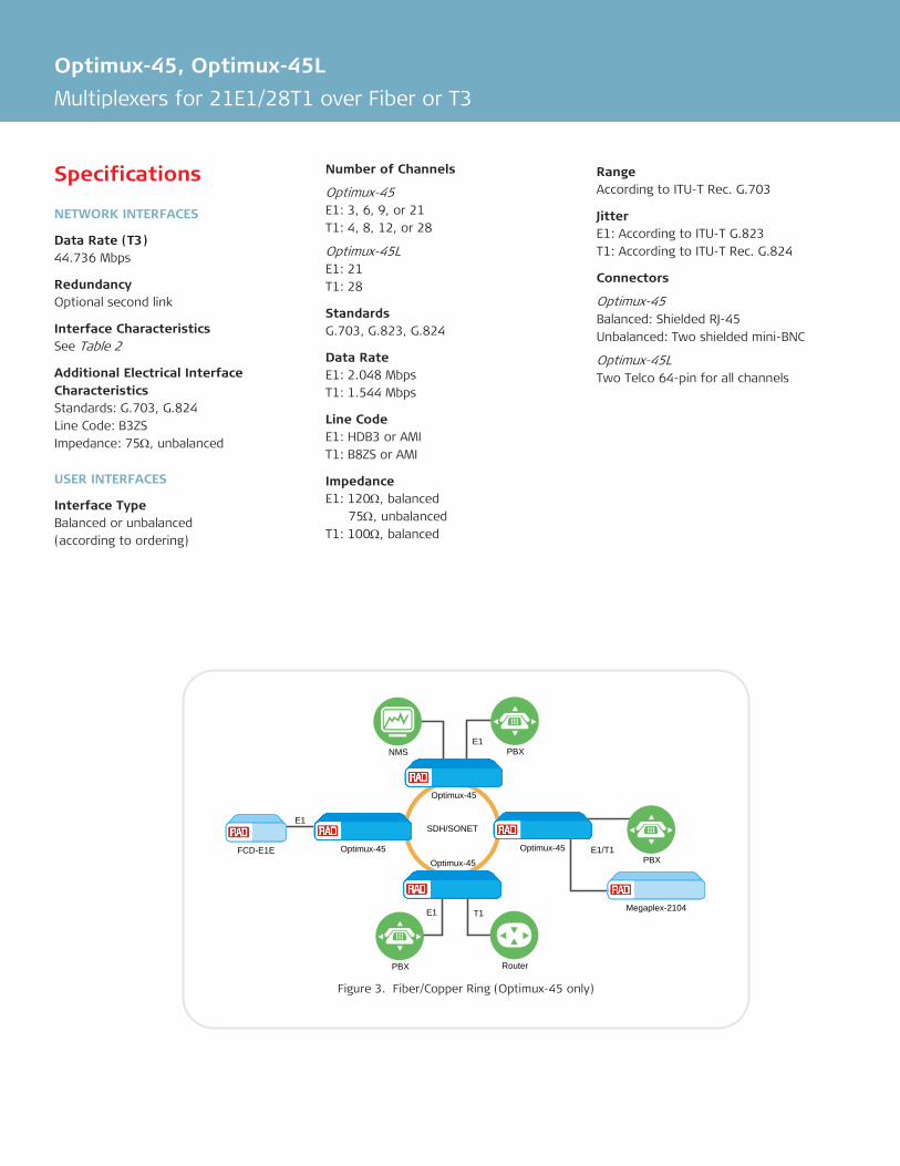
Optimux-45 supports chain and ring configurations, facilitating several E1 or T1 services at each node.
In ring topology (see Figure 2, Figure 3), Optimux-45 provides a full path protection mechanism that enables the nodes to maintain all communication services, even in the event of a link failure.
Special partially equipped versions are available for ring and chain applications with different number of tributary channels (see Table 1for details).
Ring or chain configuration is performed using RADview network management system.
MANAGEMENT AND SECURITY
Optimux-45/45L can be configured and monitored locally using an ASCII terminal connected to the control port or remotely via the Ethernet management port using:
• RADview-EMS running in a Windows or Unix environment
• Web-based remote access terminal
• Telnet.
Inband management of a remote Optimux-45/45L unit is performed via the fiber optic/coax uplink.
Ordering Option
No. of T1 Channels
No. of E1 Channels
4X 4 3
8X 8 6
12X 12 9
21X − 21 (unbalanced)
28X 28 21
Table 1. Tributary Channel Options (Optimux-45 only)
Data Sheet
DIAGNOSTICS
To facilitate system diagnostics, Optimux-45/45L features LED status indicators, AIS alarm generation, alarm dry contacts interface, and diagnostic loopbacks on the E1/T1 and T3 links.
RESILIENCY
When required, critical hardware components can be backed up. This ensures that any single point of failure will not disrupt the entire system. An optional hot-swappable second main link provides backup, using automatic switchover upon link failure. An optional second power supply provides power redundancy for fail-safe operation.
PHYSICAL
Optimux-45 and Optimux-45L are available as compact 1U-high units that can be mounted in a 19-inch (ANSI) or ETSI rack
Figure 2. Wireless 45-Mbps Ring (Optimux-45 only)
Optimux-45, Optimux-45L
Multiplexers for 21E1/28T1 over Fiber or T3
Specifications
NETWORK INTERFACES
Data Rate (T3) 44.736 Mbps
Redundancy Optional second link
Interface Characteristics See Table 2
Additional Electrical Interface Characteristics Standards: G.703, G.824 Line Code: B3ZS Impedance: 75Ω, unbalanced
USER INTERFACES
Interface Type Balanced or unbalanced (according to ordering)
Number of Channels
Optimux-45 E1: 3, 6, 9, or 21 T1: 4, 8, 12, or 28
Optimux-45L E1: 21 T1: 28
Standards G.703, G.823, G.824
Data Rate E1: 2.048 Mbps T1: 1.544 Mbps
Line Code E1: HDB3 or AMI T1: B8ZS or AMI
Impedance E1: 120Ω, balanced 75Ω, unbalanced T1: 100Ω, balanced
Range According to ITU-T Rec. G.703
Jitter E1: According to ITU-T G.823 T1: According to ITU-T Rec. G.824
Connectors
Optimux-45 Balanced: Shielded RJ-45 Unbalanced: Two shielded mini-BNC
Optimux-45L Two Telco 64-pin for all channels
SDH/SONET
Optimux-45
E1
Optimux-45 Optimux-45
Optimux-45
PBXNMS
FCD-E1EPBX
PBX Router
Megaplex-2104
E1
E1 T1
E1/T1
Figure 3. Fiber/Copper Ring (Optimux-45 only)
Data Sheet
MANAGEMENT
Control Port Interface: RS-232 Connector: DB-9
Ethernet Port Interface: 10BaseT Connector: RJ-45
TIMING
Station Clock Optional external station clock input, using RJ-45 connector via optional station clock module
Note: Station click is not available for wireless
signal support of Optimux-45 units.
MONITORING
Monitoring Built-in monitoring capabilities of each one of the tributary input channels
Indicators PWR (green/red) – power is ON (green),
power is faulty (red), power is OFF (no light)
LINK A/B SYNC LOSS (red) – DS3 signal is not detected or out of frame in Link A/B
LINK A/B AIS (yellow) – AIS signal is detected in Link A/B
MAJOR (red) – major alarm MINOR (yellow) – minor alarm TEST (yellow) – unit is in test mode
(Loopback) FLT (red) – reserved for future use
Alarm Relay DB-9 connector with dry relay contacts, for major and minor alarms
DIAGNOSTICS
LLB – Local Loopback on the E1/T1 layer and DS3 layer (LLB on DS3 layer not supported in daisy chain and ring applications) RLB – Remote Loopback on the E1/T1 layer and DS3 layer
GENERAL
Power Number of power supplies: one or two (power sharing and redundancy)
AC Power Module: 100 to 240 VAC, 50/60 Hz; max. 90VA (Optimux-45), max. 70 VA (Optimux-45L) DC Power Module: -48 VDC (-40 to -72 VDC), max. 30W 24 VDC (±10%), Max. 30W
Physical Height: 4.4 cm (1.7 in) Width: 43.8 cm (17 in) Depth: 24 cm (9.4 in) Weight: Optimux-45: 4.5 kg (11.3 lb) Optimux-45L: 3.8 kg (8.4 lb)
Environment
Temperature:
Optimux-45 AC units: 0°–50°C (32°–122°F) DC units: -22°–65°C (-7.6°–149°F)
Optimux-45L 0–55°C (32–131°F)
Humidity: up to 90%, non-condensing
Optimux-45, Optimux-45L
Multiplexers for 21E1/28T1 over Fiber or T3
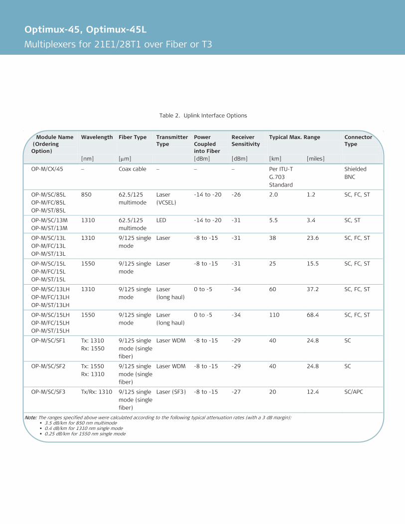
Table 2. Uplink Interface Options
Module Name (Ordering Option)
Wavelength Fiber Type Transmitter Type
Power Coupled into Fiber
Receiver Sensitivity
Typical Max. Range Connector Type
[nm] [µm] [dBm] [dBm] [km] [miles]
OP-M/CX/45 − Coax cable − − − Per ITU-T G.703 Standard
Shielded BNC
OP-M/SC/85L OP-M/FC/85L OP-M/ST/85L
850 62.5/125 multimode
Laser (VCSEL)
-14 to -20 -26 2.0 1.2 SC, FC, ST
OP-M/SC/13M OP-M/ST/13M
1310 62.5/125 multimode
LED -14 to -20 -31 5.5 3.4 SC, ST
OP-M/SC/13L OP-M/FC/13L OP-M/ST/13L
1310 9/125 single mode
Laser -8 to -15 -31 38 23.6 SC, FC, ST
OP-M/SC/15L OP-M/FC/15L OP-M/ST/15L
1550 9/125 single mode
Laser -8 to -15 -31 25 15.5 SC, FC, ST
OP-M/SC/13LH OP-M/FC/13LH OP-M/ST/13LH
1310 9/125 single mode
Laser (long haul)
0 to -5 -34 60 37.2 SC, FC, ST
OP-M/SC/15LH OP-M/FC/15LH OP-M/ST/15LH
1550 9/125 single mode
Laser (long haul)
0 to -5 -34 110 68.4 SC, FC, ST
OP-M/SC/SF1 Tx: 1310 Rx: 1550
9/125 single mode (single fiber)
Laser WDM -8 to -15 -29 40 24.8 SC
OP-M/SC/SF2 Tx: 1550 Rx: 1310
9/125 single mode (single fiber)
Laser WDM -8 to -15 -29 40 24.8 SC
OP-M/SC/SF3 Tx/Rx: 1310 9/125 single mode (single fiber)
Laser (SF3) -8 to -15 -27 20 12.4 SC/APC
Note: The ranges specified above were calculated according to the following typical attenuation rates (with a 3 dB margin): 3.5 dB/km for 850 nm multimode 0.4 dB/km for 1310 nm single mode 0.25 dB/km for 1550 nm single mode
Data Sheet
Ordering
RECOMMENDED CONFIGURATIONS
OP-45/B/28X/AC/R/CX
OP-45/B/28X/48/R/SC/13L/D
OP-45/B/28X/AC/R/ST/13L/D
OP-45L/B/AC/R/SC/13L
OP-45L/B/48/R/SC/13L/D
SPECIAL CONFIGURATIONS
Please contact your local RAD partner for additional configuration options.
SUPPLIED ACCESSORIES
AC power cord (when AC power supply is ordered)
DC connection kit (when DC power supply is ordered)
CBL-OP-45 Monitoring cable
DB9F-DB9M Terminal cross adapter
RM-34 Hardware kit for mounting one Optimux-45/45L unit into a 19-inch rack
Fiber Optic Link
Optimux-45 Optimux-45
SDH/SONET
FOM-T3
Fiber Optic LinkT3 Coax
ADM
E1/T1
Figure 4. Daisy Chain Application (Optimux-45 only)
International Headquarters 24 Raoul Wallenberg Street Tel Aviv 69719, Israel Tel. 972-3-6458181 Fax 972-3-6498250, 6474436 E-mail [email protected]
North America Headquarters 900 Corporate Drive Mahwah, NJ 07430, USA Tel. 201-5291100 Toll free 1-800-4447234 Fax 201-5295777 E-mail [email protected]
www.rad.com Order this publication by Catalog No. 803201
328-1
00-0
5/1
4 () Sp
ecificatio
ns are
subje
ct to ch
ange
with
out p
rior n
otice
. 1
988–2014 R
AD
Data Co
mm
unicatio
ns Ltd
. The R
AD
nam
e, lo
go, lo
gotyp
e, and th
e term
s EtherA
ccess, TD
MoIP an
d TD
MoIP D
riven, an
d
the p
roduct n
ames O
ptim
ux an
d IPm
ux, are
registe
red trad
em
arks of R
AD
Data C
om
municatio
ns Ltd
. All o
ther trad
em
arks are th
e p
roperty o
f their re
spective
hold
ers.
Optimux-45, Optimux-45L
Multiplexers for 21E1/28T1 over Fiber or T3
Data Sheet
OPTIONAL ACCESSORIES
CBL-DB9F-DB9M-STR Terminal straight cable
CBL-TELCO-OPEN/2M Adaptor cable Telco 64-pin, open ended, 2m long
Note: Two Telco-Open cable sets need to be
ordered to support all of the tributary channels.
CBL-TELCO-TELCO/2M Extension cable for balanced interface, Telco 64-pin to Telco 64-pin, 2m long
CBL-MINIBNC-BNC Mini-BNC to BNC adapter cable for Optimux-45
OP-A-ADAPTOR-% Optional patch panel interface adaptors for Optimux-45L to convert Telco connector into channel connectors
Legend
% Patch panel interface:
21BNC-45L Patch panel with 21 BNC unbalanced E1 interfaces, includes one CBL-TELCO-TELCO/UB cable
28RJ Patch panel with 28 balanced E1/T1 RJ-45 interfaces, includes two CBL-TELCO-TELCO/2M cables
CBL-TELCO-TELCO/UB Extension cable for unbalanced interface for Optimux-45L, Telco 64-pin to Telco 64-pin, 2m long
RM-34/ETSI Hardware kit for mounting one Optimux-45/45L unit into a 19-inch ETSI rack
WM-34 Hardware kit for mounting one Optimux-45/45L unit on the wall