Embed Size (px)
Citation preview
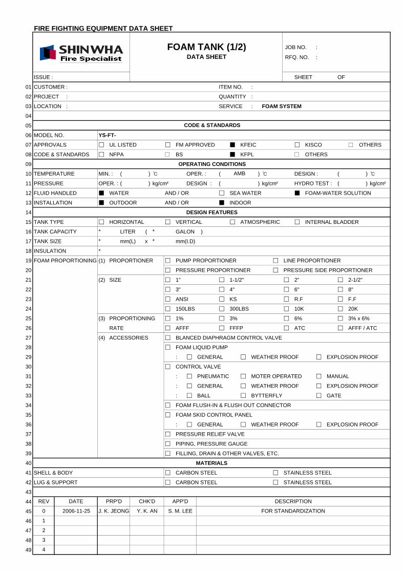
FIRE FIGHTING EQUIPMENT DATA SHEET
JOB NO. :
RFQ. NO. :
ISSUE : SHEET OF
01 CUSTOMER : ITEM NO. :
02 PROJECT : QUANTITY :
03 LOCATION : SERVICE : FOAM SYSTEM
04
05
06 MODEL NO. YS-FT-
07 APPROVALS UL LISTED FM APPROVED KFEIC KISCO □ OTHERS
08 CODE & STANDARDS NFPA □ BS KFPL □ OTHERS
09 OPERATING CONDITIONS
10 TEMPERATURE MIN. : ( ) ℃ OPER. : ( ) ℃ DESIGN : ( ) ℃
11 PRESSURE OPER. : ( ) kg/cm² DESIGN : ( ) kg/cm² HYDRO TEST : ( ) kg/cm²
12 FLUID HANDLED WATER AND / OR SEA WATER FOAM-WATER SOLUTION
13 INSTALLATION OUTDOOR AND / OR INDOOR
14 DESIGN FEATURES
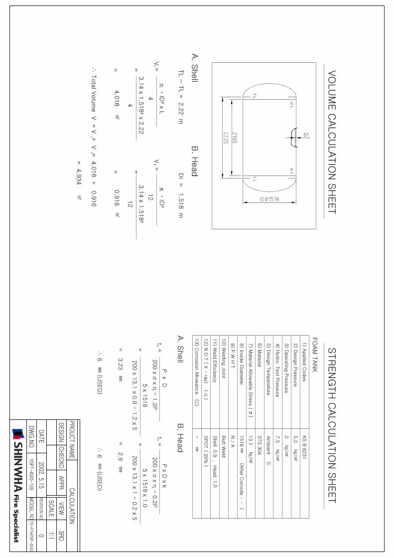
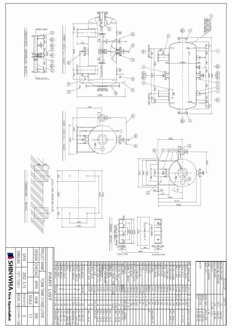
15 TANK TYPE HORIZONTAL VERTICAL ATMOSPHERIC INTERNAL BLADDER
16 TANK CAPACITY LITER ( GALON )
17 TANK SIZE mm(L) x mm(I.D)
18 INSULATION *
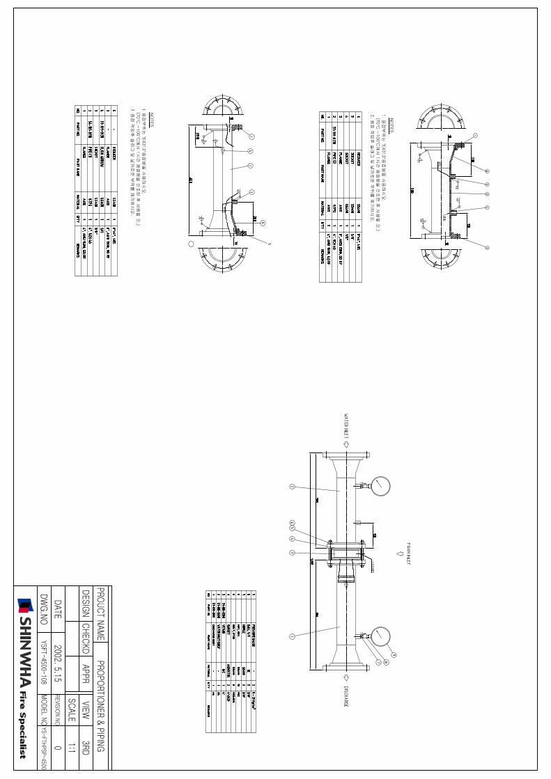
19 FOAM PROPORTIONING (1) PROPORTIONER PUMP PROPORTIONER LINE PROPORTIONER
20 PRESSURE PROPORTIONER PRESSURE SIDE PROPORTIONER
21 (2) SIZE 1" 1-1/2" 2" 2-1/2"
22 3" 4" 6" 8"
23 ANSI KS R.F F.F
24 150LBS 300LBS 10K 20K
25 (3) PROPORTIONING 1% 3% 6% 3% x 6%
26 RATE AFFF FFFP ATC AFFF / ATC
27 (4) ACCESSORIES BLANCED DIAPHRAGM CONTROL VALVE
28 FOAM LIQUID PUMP
29 : GENERAL WEATHER PROOF EXPLOSION PROOF
30 CONTROL VALVE
31 : PNEUMATIC MOTER OPERATED MANUAL
32 : GENERAL WEATHER PROOF EXPLOSION PROOF
33 : BALL BYTTERFLY GATE
34 FOAM FLUSH-IN & FLUSH OUT CONNECTOR
35 FOAM SKID CONTROL PANEL
36 : GENERAL WEATHER PROOF EXPLOSION PROOF
37 PRESSURE RELIEF VALVE
38 PIPING, PRESSURE GAUGE
39 FILLING, DRAIN & OTHER VALVES, ETC.
40 MATERIALS
41 SHELL & BODY CARBON STEEL STAINLESS STEEL
42 LUG & SUPPORT CARBON STEEL STAINLESS STEEL
43
44
45
46
47
48
49 4
3
2
1
DESCRIPTION
0 2006-11-25 J. K. JEONG Y. K. AN S. M. LEE FOR STANDARDIZATION
REV DATE PRP'D CHK'D APP'D
FOAM TANK (1/2)DATA SHEET
AMB
CODE & STANDARDS
* *
* *
FIRE FIGHTING EQUIPMENT DATA SHEET
JOB NO. :
RFQ. NO. :
ISSUE : SHEET OF
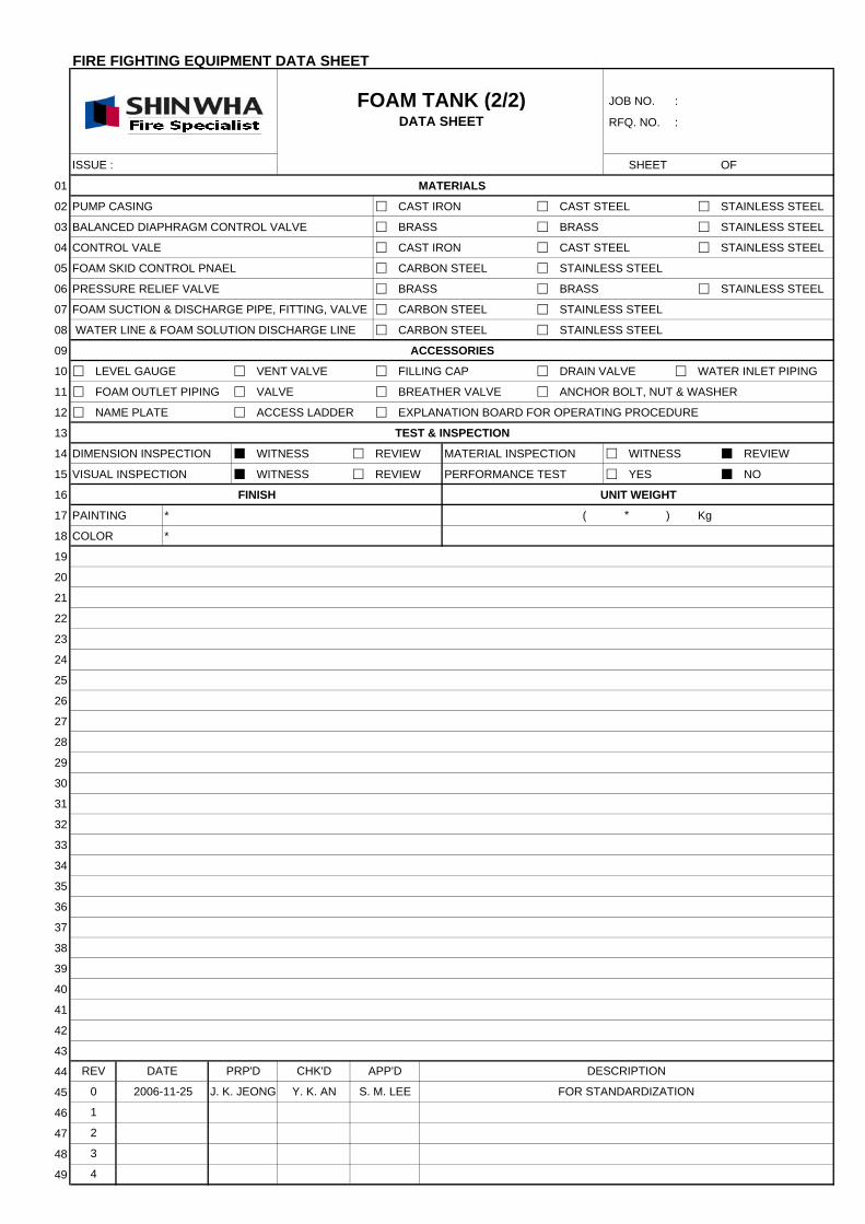
01 MATERIALS
02 PUMP CASING CAST IRON CAST STEEL STAINLESS STEEL
03 BALANCED DIAPHRAGM CONTROL VALVE BRASS BRASS STAINLESS STEEL
04 CONTROL VALE CAST IRON CAST STEEL STAINLESS STEEL
05 FOAM SKID CONTROL PNAEL CARBON STEEL STAINLESS STEEL
06 PRESSURE RELIEF VALVE BRASS BRASS STAINLESS STEEL
07 FOAM SUCTION & DISCHARGE PIPE, FITTING, VALVE CARBON STEEL STAINLESS STEEL
08 WATER LINE & FOAM SOLUTION DISCHARGE LINE CARBON STEEL STAINLESS STEEL
09 ACCESSORIES
10 LEVEL GAUGE VENT VALVE FILLING CAP DRAIN VALVE WATER INLET PIPING
11 FOAM OUTLET PIPING VALVE BREATHER VALVE ANCHOR BOLT, NUT & WASHER
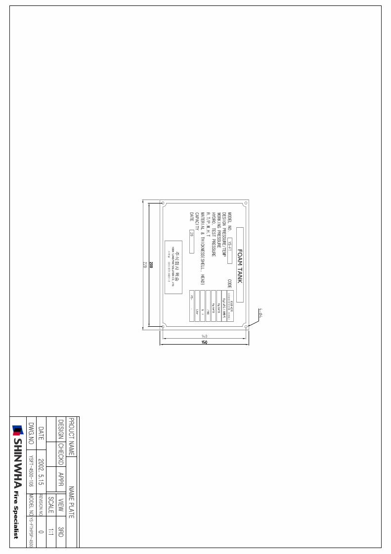
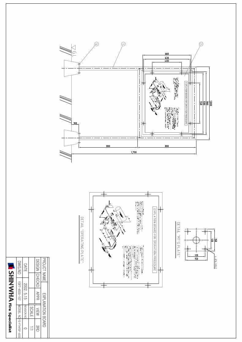
12 NAME PLATE ACCESS LADDER EXPLANATION BOARD FOR OPERATING PROCEDURE
13 TEST & INSPECTION
14 DIMENSION INSPECTION WITNESS REVIEW MATERIAL INSPECTION WITNESS REVIEW
15 VISUAL INSPECTION WITNESS REVIEW PERFORMANCE TEST YES NO
16 FINISH UNIT WEIGHT
17 PAINTING * ( ) Kg
18 COLOR *
19
20
21
22
23
24
25
26
27
28
29
30
31
32
33
34
35
36
37
38
39
40
41
42
43
44
45
46
47
48
49
FOR STANDARDIZATIONS. M. LEEJ. K. JEONG
4
2
3
Y. K. AN2006-11-250
1
CHK'D DESCRIPTIONPRP'D APP'DDATEREV
*
FOAM TANK (2/2)DATA SHEET
1JANUARY, 2006 HD191PAGE OF 4
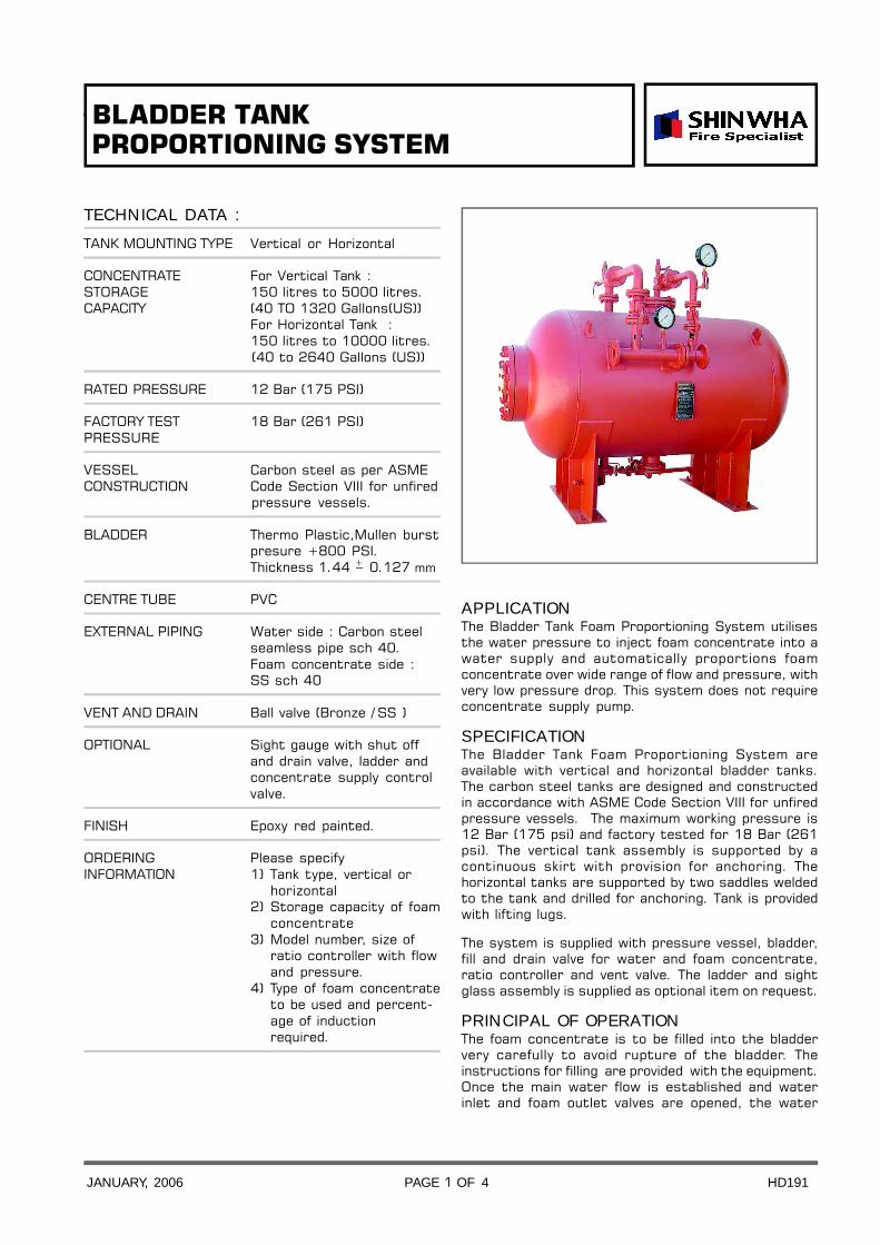
TECHNICAL DATA :
TANK MOUNTING TYPE Vertical or Horizontal
CONCENTRATE For Vertical Tank :STORAGE 150 litres to 5000 litres.CAPACITY (40 TO 1320 Gallons(US))
For Horizontal Tank :150 litres to 10000 litres.(40 to 2640 Gallons (US))
RATED PRESSURE 12 Bar (175 PSI)
FACTORY TEST 18 Bar (261 PSI)PRESSURE
VESSEL Carbon steel as per ASMECONSTRUCTION Code Section VIII for unfired
pressure vessels.
BLADDER Thermo Plastic,Mullen burstpresure +800 PSI.Thickness 1.44 + 0.127 mm
CENTRE TUBE PVC
EXTERNAL PIPING Water side : Carbon steelseamless pipe sch 40.Foam concentrate side :SS sch 40
VENT AND DRAIN Ball valve (Bronze / SS )
OPTIONAL Sight gauge with shut offand drain valve, ladder andconcentrate supply controlvalve.
FINISH Epoxy red painted.
ORDERING Please specifyINFORMATION 1) Tank type, vertical or
horizontal2) Storage capacity of foam
concentrate3) Model number, size of
ratio controller with flowand pressure.
4) Type of foam concentrateto be used and percent-age of induction
required.
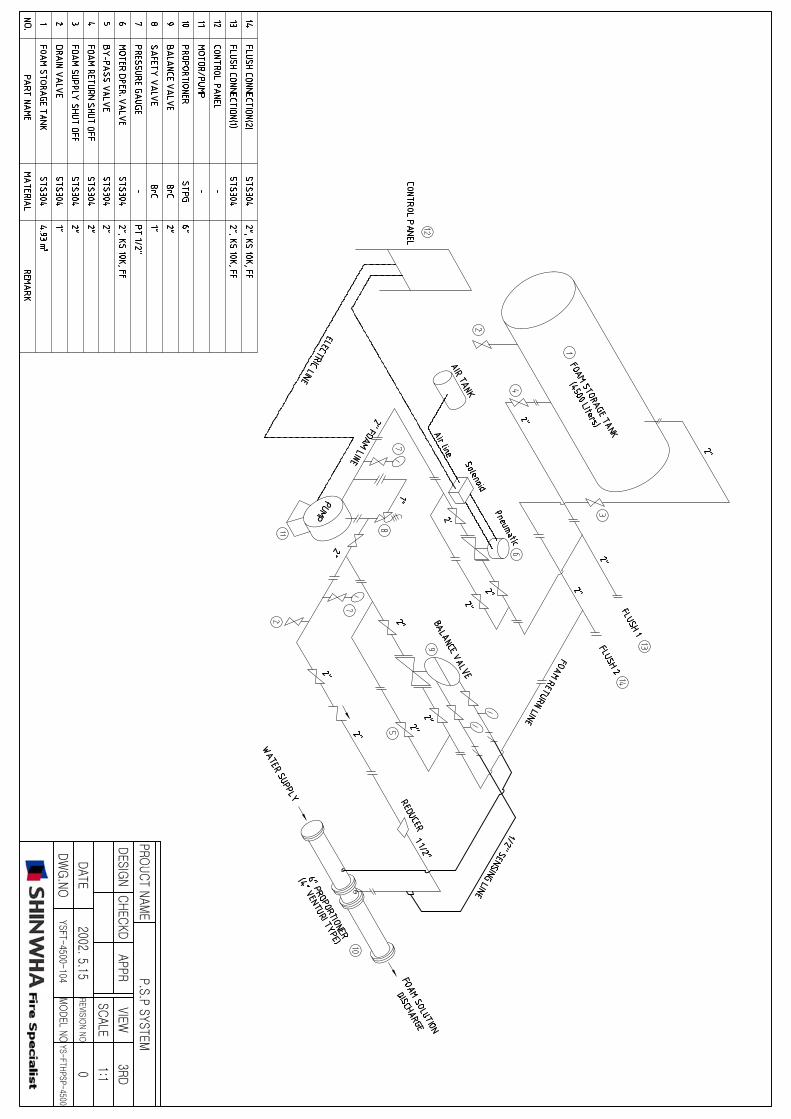
APPLICATIONThe Bladder Tank Foam Proportioning System utilisesthe water pressure to inject foam concentrate into awater supply and automatically proportions foamconcentrate over wide range of flow and pressure, withvery low pressure drop. This system does not requireconcentrate supply pump.
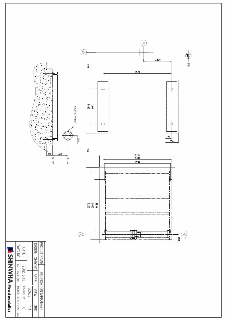
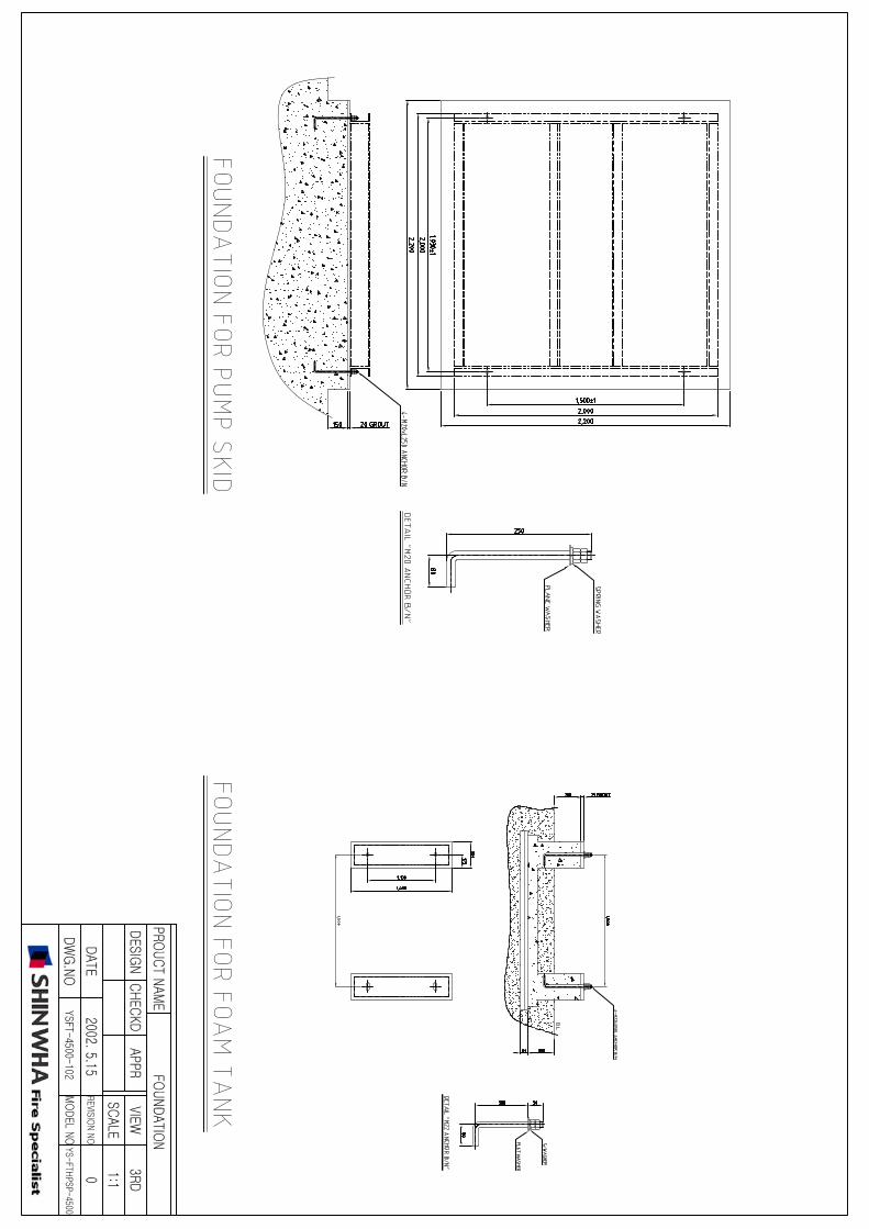
SPECIFICATIONThe Bladder Tank Foam Proportioning System areavailable with vertical and horizontal bladder tanks.The carbon steel tanks are designed and constructedin accordance with ASME Code Section VIII for unfiredpressure vessels. The maximum working pressure is12 Bar (175 psi) and factory tested for 18 Bar (261psi). The vertical tank assembly is supported by acontinuous skirt with provision for anchoring. Thehorizontal tanks are supported by two saddles weldedto the tank and drilled for anchoring. Tank is providedwith lifting lugs.
The system is supplied with pressure vessel, bladder,fill and drain valve for water and foam concentrate,ratio controller and vent valve. The ladder and sightglass assembly is supplied as optional item on request.
PRINCIPAL OF OPERATIONThe foam concentrate is to be filled into the bladdervery carefully to avoid rupture of the bladder. Theinstructions for filling are provided with the equipment.Once the main water flow is established and waterinlet and foam outlet valves are opened, the water
BLADDER TANK PROPORTIONING SYSTEM
2JANUARY, 2006 HD191PAGE OF 4
enters the area between vessel wall and bladder,applying pressure to the bladder. The foam concentrateis forced out of the bladder through the foam outletpipe and into the ratio controller through meteringorifice. The concentrate pressure and water inletpressure at ratio controller will be same, as the mainwater supply pressure is utilised to expel the foamfrom the bladder. The water flowing through the ratiocontroller jet creates a low pressure area commonboth to down stream water and foam concentrate.This injects the concentrate in to the ratio controllerthrough an accurate sized orifice proportioned towater venturi. This ensures correct proportioning overa wide range of flow condition.
The bladder tank proportioning system operates onsame principle as that of a balance pressureproportioning system. In bladder system, the bladderis used as diaphragm to separate the water and foamconcentrate within the tank. The foam concentrate isinjected into the ratio controller utilising waterpressure.
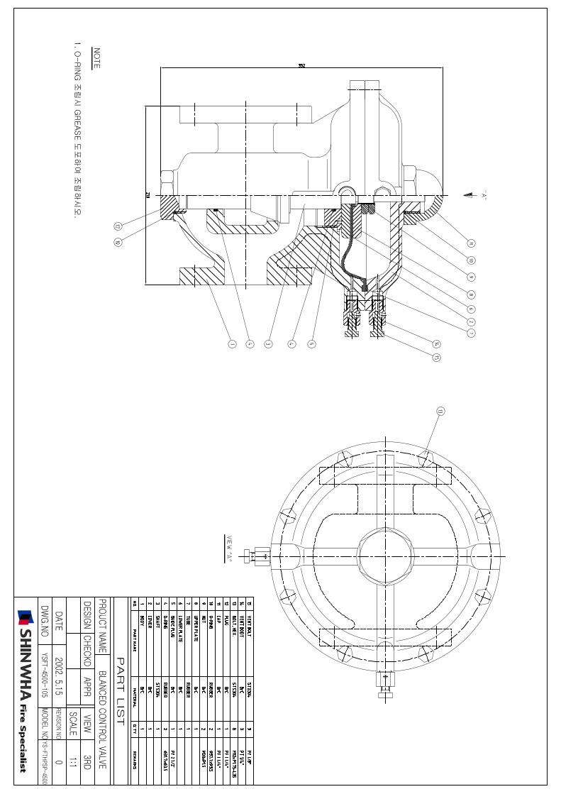
The system is also supplied with foam concentratecontrol valve as an optional item. The valve allowsconcentrate flow only when minimum of 3.0 kg/sq.cm.water pressure is established in the system. Forpressure drop and flow characteristics refer catalogueof ratio controller.
INSTALLATION, INSPECTIONAND MAINTENANCEAn installation, inspection and maintenance manual isprovided with each unit. The manual provides detailschematic, initial procedure, inspection andmaintenance procedures. The instruction manual mustbe read carefully and followed during installation andcommissioning of the system.
After few initial successful tests an authorised personmust be trained to perform inspection and testing ofthe system. It is recommended to carry out physicalinspection of the system regularly, the inspectionshould verify that no damages have taken place to anycomponent and all the valves are in their properposition as per the system requirement. The systemshould be fully tested at least once in a year and inaccordance with applicable NFPA/TAC code or inaccordance to the guidelines of the organisation havinglocal jurisdiction.
Do not turn off the system or any valve to repair ortest the system, without placing a roving Fire Patrolin the area covered by the system. The patrol shouldcontinue until the system is put back in service. Alsoinform the local security personnel and the controlroom so that a false alarm is not signalled.
CAUTION1. Do not weld on the tank as it may damage the
bladder.
2. Release pressure before an inspection and
maintenance of the system.
3. Sight glass is not pressure tight, so before takingconcentrate level reading, tank pressure must bereleased.
4. The bladder tank is to be installed under a shade toavoid direct sunlight on the equipment.
NOTE1. The foam concentrate is to be filled in the
bladder very carefully to avoid rupture ofthe bladder. The filling guideline provided withthe equipment must be adhered to strictly.
2. Air supply with regulator (0 to 1.0 kg/sqcm) requiredduring filling procedure, to be provided by user/installer
3.Water supply at 0-1.5 kg/sqcm required for tankfilling during commissioning , to be provided byinstaller/user.
3JANUARY, 2006 HD191PAGE OF 4
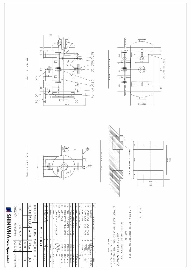
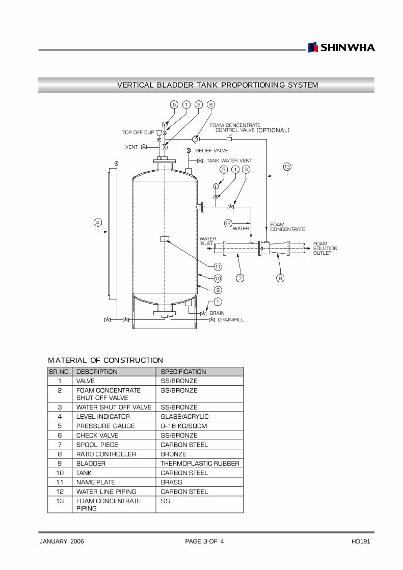
MATERIAL OF CONSTRUCTIONSR.NO. DESCRIPTION SPECIFICATION
1 VALVE SS/BRONZE
2 FOAM CONCENTRATE SS/BRONZESHUT OFF VALVE
3 WATER SHUT OFF VALVE SS/BRONZE4 LEVEL INDICATOR GLASS/ACRYLIC
5 PRESSURE GAUGE 0-16 KG/SQCM6 CHECK VALVE SS/BRONZE
7 SPOOL PIECE CARBON STEEL8 RATIO CONTROLLER BRONZE9 BLADDER THERMOPLASTIC RUBBER
10 TANK CARBON STEEL11 NAME PLATE BRASS
12 WATER LINE PIPING CARBON STEEL13 FOAM CONCENTRATE SS
PIPING
VERTICAL BLADDER TANK PROPORTIONING SYSTEM
(OPTIONAL)
4JANUARY, 2006 HD191PAGE OF 4
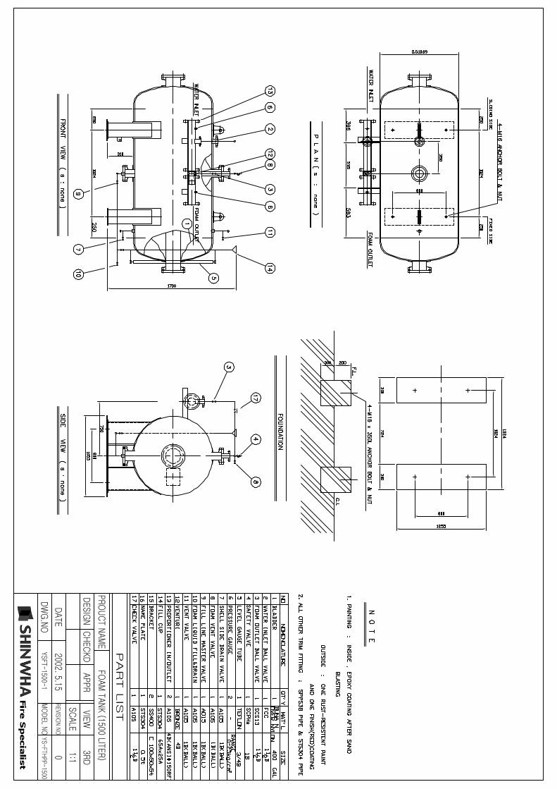
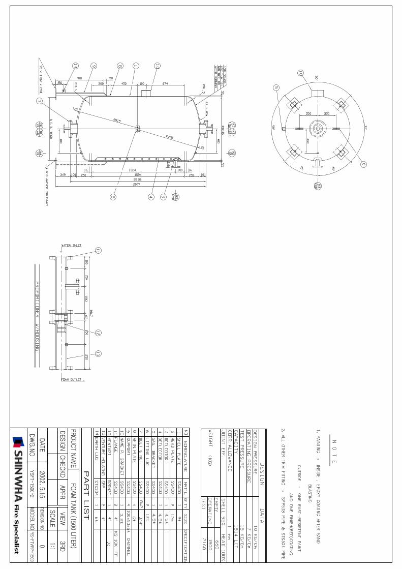
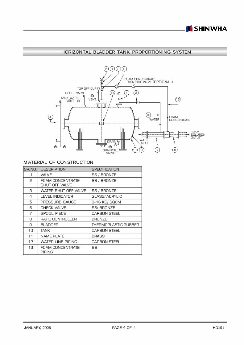
HORIZONTAL BLADDER TANK PROPORTIONING SYSTEM
MATERIAL OF CONSTRUCTIONSR.NO. DESCRIPTION SPECIFICATION
1 VALVE SS / BRONZE
2 FOAM CONCENTRATE SS / BRONZESHUT OFF VALVE
3 WATER SHUT OFF VALVE SS / BRONZE4 LEVEL INDICATOR GLASS/ ACRYLIC5 PRESSURE GAUGE 0-16 KG/ SQCM
6 CHECK VALVE SS/ BRONZE7 SPOOL PIECE CARBON STEEL
8 RATIO CONTROLLER BRONZE9 BLADDER THERMOPLASTIC RUBBER
10 TANK CARBON STEEL11 NAME PLATE BRASS12 WATER LINE PIPING CARBON STEEL
13 FOAM CONCENTRATE SSPIPING
(OPTIONAL)