Embed Size (px)
Citation preview
DoepkeThe experts in residual current protection technology
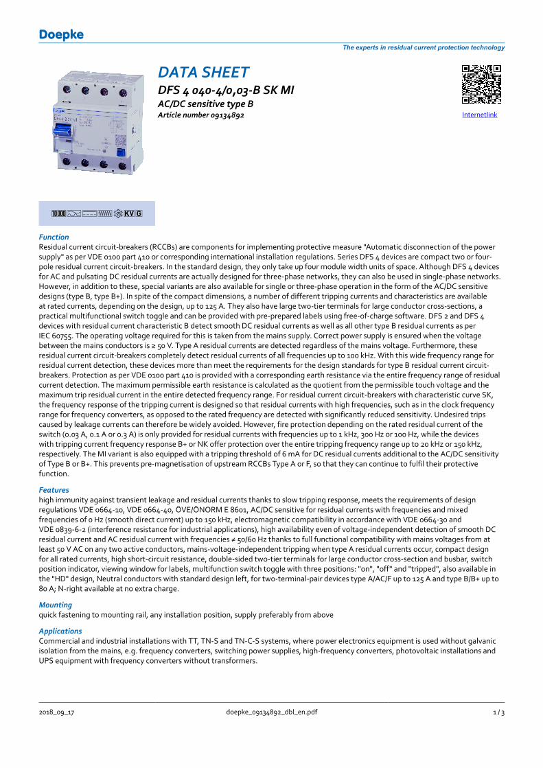
DATA SHEETDFS 4 040-4003-B SK MIACDC sensitive type BArticle number 09134892 Internetlink
1AGFTkg
FunctionResidual current circuit-breakers (RCCBs) are components for implementing protective measure Automatic disconnection of the powersupply as per VDE 0100 part 410 or corresponding international installation regulations Series DFS 4 devices are compact two or four-pole residual current circuit-breakers In the standard design they only take up four module width units of space Although DFS 4 devicesfor AC and pulsating DC residual currents are actually designed for three-phase networks they can also be used in single-phase networksHowever in addition to these special variants are also available for single or three-phase operation in the form of the ACDC sensitivedesigns (type B type B+) In spite of the compact dimensions a number of different tripping currents and characteristics are availableat rated currents depending on the design up to 125 A They also have large two-tier terminals for large conductor cross-sections apractical multifunctional switch toggle and can be provided with pre-prepared labels using free-of-charge software DFS 2 and DFS 4devices with residual current characteristic B detect smooth DC residual currents as well as all other type B residual currents as perIEC 60755 The operating voltage required for this is taken from the mains supply Correct power supply is ensured when the voltagebetween the mains conductors is ge 50 V Type A residual currents are detected regardless of the mains voltage Furthermore theseresidual current circuit-breakers completely detect residual currents of all frequencies up to 100 kHz With this wide frequency range forresidual current detection these devices more than meet the requirements for the design standards for type B residual current circuit-breakers Protection as per VDE 0100 part 410 is provided with a corresponding earth resistance via the entire frequency range of residualcurrent detection The maximum permissible earth resistance is calculated as the quotient from the permissible touch voltage and themaximum trip residual current in the entire detected frequency range For residual current circuit-breakers with characteristic curve SKthe frequency response of the tripping current is designed so that residual currents with high frequencies such as in the clock frequencyrange for frequency converters as opposed to the rated frequency are detected with significantly reduced sensitivity Undesired tripscaused by leakage currents can therefore be widely avoided However fire protection depending on the rated residual current of theswitch (003 A 01 A or 03 A) is only provided for residual currents with frequencies up to 1 kHz 300 Hz or 100 Hz while the deviceswith tripping current frequency response B+ or NK offer protection over the entire tripping frequency range up to 20 kHz or 150 kHzrespectively The MI variant is also equipped with a tripping threshold of 6 mA for DC residual currents additional to the ACDC sensitivityof Type B or B+ This prevents pre-magnetisation of upstream RCCBs Type A or F so that they can continue to fulfil their protectivefunction
Featureshigh immunity against transient leakage and residual currents thanks to slow tripping response meets the requirements of designregulations VDE 0664-10 VDE 0664-40 OumlVEOumlNORM E 8601 ACDC sensitive for residual currents with frequencies and mixedfrequencies of 0 Hz (smooth direct current) up to 150 kHz electromagnetic compatibility in accordance with VDE 0664-30 andVDE 0839-6-2 (interference resistance for industrial applications) high availability even of voltage-independent detection of smooth DCresidual current and AC residual current with frequencies ne 5060 Hz thanks to full functional compatibility with mains voltages from atleast 50 V AC on any two active conductors mains-voltage-independent tripping when type A residual currents occur compact designfor all rated currents high short-circuit resistance double-sided two-tier terminals for large conductor cross-section and busbar switchposition indicator viewing window for labels multifunction switch toggle with three positions on off and tripped also available inthe HD design Neutral conductors with standard design left for two-terminal-pair devices type AACF up to 125 A and type BB+ up to80 A N-right available at no extra charge
Mountingquick fastening to mounting rail any installation position supply preferably from above
ApplicationsCommercial and industrial installations with TT TN-S and TN-C-S systems where power electronics equipment is used without galvanicisolation from the mains eg frequency converters switching power supplies high-frequency converters photovoltaic installations andUPS equipment with frequency converters without transformers
2018_09_17 doepke_09134892_dbl_enpdf 1 3
DoepkeThe experts in residual current protection technology
Notessuitable for use in 50 Hz AC networks RCCBs for other frequencies available upon request Not designed for use in direct current networksor on the output side of controlled electrical equipment such as frequency converters
AccessoriesClamp covers KA Information stickers HAS Auxiliary Switches DHi Restart locking facilities WES Software BS DLSDFS
Technical Data
Technical Data DFS 4 040-4003-B SK MISeries DFS 4 B SK MINumber of poles 4Residual current type BTripping characteristic curve SKRated current (AC) 40 ARated residual current I∆n 003 ADC tripping threshold 6 mAShort-time delayed trueSelective falsemin Operating voltage range oftest circuit
250 V
max Operating voltage range oftest circuit
440 V
Minimum rated operatingvoltage (Type AAC operation)
0 V AC
Minimum rated operatingvoltage (Type B operation)
50 V AC
Non-trip time 10 msNeutral conductor position leftTripping frequency 0 Hz 150 kHzMaximum disconnection times 1 middot IΔn le 300 ms 5 middot IΔn le 40 msInternal consumption max 22 W
Load circuitSpecification Load switch contactmin Output O1 Contact opening 4 mmRated voltage (AC) 230 V 400 VRated current (AC) 40 ARated short-circuit current 10 kASurge current strength 3 kAmax Output O1 total ratedswitching capacity
500 A
Rated insulation voltage 400 VRated impulse withstand voltage 4 kVRated frequency 50 HzCurrent heat loss per currentpath
13 W
thermal Backup-fuse OCPD 40 Ashort-circuit backup-fuse SCPD 100 ABack-up fuse type gG
Screw-type terminal top and bottom (Load circuit)Protection against direct contact DGUV V3 VDE 0660-514 finger-safe and safe for back-of-handConnection C1 Maximumnumber of conductors perterminal
2 (conductors of same type and cross-section)
2018_09_17 doepke_09134892_dbl_enpdf 2 3
DoepkeThe experts in residual current protection technology
Technical Data DFS 4 040-4003-B SK MICross section solid 1-wire 15 mmsup2 50 mmsup2 2-wire 15 mmsup2 16 mmsup2Connecting capacity flexible 1-wire 15 mmsup2 50 mmsup2 2-wire 15 mmsup2 16 mmsup2Cross section stranded 1-wire 15 mmsup2 50 mmsup2 2-wire 15 mmsup2 16 mmsup2Tightening torque 25 Nm 3 NmGeneral data description General dataOperating position anymax Operating altitude aboveMSL
2000 m
Mechanical endurance min 5000 cyclesElectrical endurance min 2000 cyclesSurrounding atmosphere normal environmental conditionsStorage temperature -35 degC 75 degCAmbient temperature -25 degC 40 degCClimate resistance according to IEC 60068-2-30 humid heat cyclic (25 degC 55 degC 93 97 RH)Shock resistance 20 g 20 ms DurationFatigue limit gt 5 g (f le 80 Hz duration gt 30 min)Housing type Distributor housingMounting type Mounting railHousing material Thermoplastic resinProtection class IP20 (installed IP40)sealable trueWidth 72 mmHeight 85 mmDepth 75 mmInstallation depth 69 mmWidth (modules) 4Design requirementsStandards VDE 0664-10 VDE 0664-40 OumlVEOumlNORM E 8601Degree of pollution according toEN 60664
2
Dimensions Wiring example Diagrams
Dimensional drawing Group view
Wiring diagram
Characteristic B SK 30 mA
2018_09_17 doepke_09134892_dbl_enpdf 3 3

DoepkeThe experts in residual current protection technology
Technical Data DFS 4 040-4003-B SK MICross section solid 1-wire 15 mmsup2 50 mmsup2 2-wire 15 mmsup2 16 mmsup2Connecting capacity flexible 1-wire 15 mmsup2 50 mmsup2 2-wire 15 mmsup2 16 mmsup2Cross section stranded 1-wire 15 mmsup2 50 mmsup2 2-wire 15 mmsup2 16 mmsup2Tightening torque 25 Nm 3 NmGeneral data description General dataOperating position anymax Operating altitude aboveMSL
2000 m
Mechanical endurance min 5000 cyclesElectrical endurance min 2000 cyclesSurrounding atmosphere normal environmental conditionsStorage temperature -35 degC 75 degCAmbient temperature -25 degC 40 degCClimate resistance according to IEC 60068-2-30 humid heat cyclic (25 degC 55 degC 93 97 RH)Shock resistance 20 g 20 ms DurationFatigue limit gt 5 g (f le 80 Hz duration gt 30 min)Housing type Distributor housingMounting type Mounting railHousing material Thermoplastic resinProtection class IP20 (installed IP40)sealable trueWidth 72 mmHeight 85 mmDepth 75 mmInstallation depth 69 mmWidth (modules) 4Design requirementsStandards VDE 0664-10 VDE 0664-40 OumlVEOumlNORM E 8601Degree of pollution according toEN 60664
2
Dimensions Wiring example Diagrams
Dimensional drawing Group view
Wiring diagram
Characteristic B SK 30 mA
2018_09_17 doepke_09134892_dbl_enpdf 3 3