Embed Size (px)
Citation preview
Compact robust power relay— Type RH(M) 1003: 3 changeover contacts— Type RH(M) 1004: 4 changeover contacts
Choice of contact material— Silver, gold-bloomed (standard material)— Silver-palladium— Silver-cadmium oxide— Gold
All-or-nothing relay in plug-in case RH 1000for direct connection (2.8 mm tab connector or soldering)or plug into— Flush-mounting socket for PCB-mounting— Flush-mounting socket for soldering— Flush-mounting socket for crimping— Surface-mounting socket for wall-mounting
with threaded terminals— Surface-mounting socket for top-hat-rail-mounting
with threaded terminals
All-or-nothing relay for top-hat rail mounting RHM 1000for direct connection (2.8 mm tab connector or soldering)
DC voltage operation(also available for DC current operation) or
AC voltage operation (40 ... 70 Hz)— At f > 70 Hz: Operate value rising
Release value falling
With jog / latch button as standardfor manual operation and for position indication
LED indication in the coil circuit (optional)
Data Sheet 10/86-2.36-EN
All-or-nothing relay RH(M) 1000in plug-in case and case for top-hat rail or wall mounting

All-or-nothing relay RH(M) 1000in plug-in case and case for top-hat rail or wall-mounting 10/86-2.36 EN
Page 2 of 12
Technical notes
All-or-nothing relayAn applied energizing quantity (current or voltage) within the guar-anteed range produces a magnetic field which in turn causes therelay to operate. The operate function is ensured from the lowestguaranteed value onwards (but may also occur for lower values).The relay remains in operate condition while the energizing quan-tity is within the guaranteed range.
The assured release takes place from 5 % (DC) or 15 % (AC) ofthe highest reference value within the permitted range of the ener-gizing quantity (but may also occur for higher values).
All-or-nothing relay RH 1000This relay plugs into a matching socket. It can also be mounteddirectly.
All-or-nothing relay RHM 1000This relay is snap-fastened onto a top-hat rail or mounted directlyonto a mounting plane using two bolts.
Coil for DC voltage only(Coil without auxiliary circuit)The energizing quantity is applied directly to the coil. There is noauxiliary circuit as protection from transient overvoltages or for thelimitation of overvoltages on switch-off. The relay itself is resistenttowards transient overvoltages within the guaranteed range.Connection to A1 and A2.
Coil with simple winding and free-wheeling diodeThe coil is additionally fitted with a free-wheeling diode for voltagelimitation when the coil is switched off. Connect + to A1 or A2 asper order. There is no reverse-polarity protection. Reverse polaritywill destroy the free-wheeling diode! Connection to A1 and A2.
Coil with simple winding, reverse-polarity protection,LED indicator and free-wheeling diode (+ on A1)The coil is additionally fitted with a diode as reverse-polarityprotection and an LED indicator for coil current indication. Thefree-wheeling diode limits the voltage as the coil is switched off.Caution: external connection to A1 and B1; A2 is internally as-signed and must not be connected externally!
Coil with simple windingFor all-or-nothing relays, a coil with simple winding is the standarddesign. One energizing quantity only may be applied.
Coil with tapIn addition to both ends of the coil, a coil point in between isconnected to a pin (for example for coil current monitoring for inter-ruption).
Coil with double windingFor all-or-nothing relays with double winding, triggering by twoindependent energizing quantities is possible. Both coils have acommon connection point at one end.
Coil for DC or AC voltage (Coil with auxiliary circuit)The energizing quantity is applied to the coil via a diode (+ on A1).The coil circuit is thereby reverse-polarity-protected. A free-wheeling diode is connected in parallel to the coil. The relay is
additionally protected by protective circuitry. For AC voltage, thecoil is loaded by the energizing quantity during part of the cycleonly. During the other part of the cycle, the magnetic system isbuffered by the free-wheeling diode. For AC operation, the r.m.s.value needs to be double the value for DC voltage operation. Con-nection to A1 and A2; B1 is internally assigned and must not beconnected externally!
Coil for DC or AC voltage and LED Indicator(Coil with auxiliary circuit)Design as for the coils for DC or AC voltage (coil with auxiliarycircuit) with additional LED for operation indication. Connection toA1 and A2; B1 is internally assigned and must not be connectedexternally!
Contact materialOur standard contact material is silver that is gold-bloomed forprotection during storage. Other contact materials are offered forselection. Please see the Guide Sheet for details.
Mounting bracketUsed for individual mounting of one RH1000 on a mounting plane.Available in packs of 25.
Retaining clipEach socket is supplied with a retaining clip that will hold anRH1000 firmly inside the socket. Retaining clips are availableseparately in packs of 25.
SocketsSockets are available for RH1003 and RH1004. Each flush-mount-ing socket is supplied with a retaining clip.
– Flush-mounting socket for PCB-mounting: Flush-mounting socket with soldering pins (0.5 mm x 1 mm) for mounting in printed circuit boards.
– Flush-mounting socket for soldered connection: Flush-mounting socket with soldering tag.
– Flush-mounting socket for crimping: Flush-mounting socket with crimp contacts.
– Surface-mounting socket with threaded terminals: Surface-mounting sockets are available for RH1003 (one standard design for all RH1003 versions) and for RH1004 (premium type and special designs). They are mounted with two bolts on a mounting plane.
– Surface-mounting socket with threaded terminals and snapfixing for top-hat rail: Identical to the surface-mounting socketwith threaded terminals except that it is not bolt-mounted butsnap-fixed onto a top-hat rail. The arrow on the snap fixingshould point down during installation.
Spare cover caps for surface-mounting socketsAs replacement for damaged or lost cover caps. Available in setsof 2.
Snap fixing for a top-hat railSnap fixing for a top-hat rail on a mounting plate, suitable for asurface-mounting socket with threaded terminals. It is used prefer-entially for the retrofitting of such sockets.

04.01 Page 3 of 12
All-or-nothing relay RH(M) 1000in plug-in case and case for top-hat rail or wall-mounting 10/86-2.36 EN
Technical data (Please note the general hints in the Data Sheet 86-1.00 EN)
General data RH 1000(Relay in plug-in case)
RHM 1000 (Relay for top-hat railand wall-mounting)
Degree of protectionRelay (without connection area)Relay (terminals with covering)Flush-mounting socketSurface-mounting socket with covering
IP 40IP 00IP 00IP 20
IP 40IP 00––
InstallationRelayFlush-mounting socketSurface-mounting socket
boltboltbolt, snap
bolt, snap––
WeightRelayFlush-mounting socketSurface-mounting socketSurface-mounting socket with snap fixing
approx. 150 gapprox. 35 gapprox. 100 gapprox. 170 g
approx.150 g–––
Electrical connections (see also “circuit diagrams“)Caution: For direct connection of the RH(M) 1000 please take into account the basic insulation between contact circuits and operating circuit!
Relay (ensure shock protection during installation) plugging:max. 0.75 mm2 flexiblewith tab connector 2.8 x 0.8 mmsoldering:max. 0.75 mm2 solid
plugging:max. 0.75 mm2 flexiblewith tab connector 2.8 x 0.8 mmsoldering:max. 0.75 mm2 solid
Flush-mounting socket (ensure shock protection dur. install.)for PCB-mountingfor solderingfor crimping
soldering pin 1 x 0.5 mmmax. 0.75 mm2 solidmax. 0.75 mm2 flexible
–
Surface-mounting socket threaded terminalsmax. 2.5 mm2 solidmax. 2.5 mm2 flexible(use wire end ferrules!)
–
Mounting orientation arbitrary arbitrary
Mechanical service life 20 x 106 switching operations 20 x 106 switching operations
Permissible switching frequency 200 switching operations/min. 200 switching operations/min.
Climate class 3K3max. 85 % relative humiditymax. 25 g/m3 abs. humidity
3K3max. 85 % relative humiditymax. 25 g/m3 abs. humidity
Permissible temperature ranges for coilsTransport and storage temperaturesAmbient temperatureMaximum surface temperature
(with all maximum permissible values for ambienttemperature, coil voltage, contact rating)
DC DC/AC-45...+100 °C -45...+100 °C-25...+ 70 °C -25...+ 65 °C+85 °C +80 °C
DC DC/AC-45...+100 °C -45...+100 °C-25...+ 70 °C -25...+ 65 °C+85 °C +80 °C

All-or-nothing relay RH(M) 1000in plug-in case and case for top-hat rail or wall-mounting 10/86-2.36 EN
Page 4 of 12
Technical data (Please note the general hints in the Data Sheet 86-1.00 EN)
The insulation between coil circuit and contact circuit complies with the specifications for basic insulation.
Coil circuitNominal Nominal Resistancevoltage range Rcoil Rser.
Nominalconsumption
max. permissible operating range Vmin. to Vmax.at ambient temperature
(±10 % at 20 °C)
RH 1000 and RHM 1000 (specified operate value 260 AW)
Coil for DC voltage only -25 °C...+40 °C -5 °C...+40 °C -25 °C...+70 °C
220/212 V DC 9.6... 13.2 V 78 Ω –220/224 V DC 19.2... 26.4 V 270 Ω –220/248 V DC 38.4... 52.8 V 1200 Ω –220/260 V DC 48.0... 66.0 V 2150 Ω –110/125 V DC 88.0...137.5 V 7700 Ω –220/250 V DC 176.0...242.0 V 26000 Ω –
1.85 W2.13 W1.92 W1.67 W1.57 W1.86 W
7.9... 15.1 V14.2... 27.3 V31.7... 60.6 V40.4... 77.6 V80.1...153.2 V
154.7...294.3 V
7.9... 16.4 V14.2... 29.8 V31.7... 66.2 V40.4... 84.7 V80.1...167.2 V
154.7...321.3 V
8.6... 15.1 V15.6... 27..3 V34.9... 60.6 V44.4... 77.6 V88.1...153.2 V
170.2...294.3 V
others per order from 5...250 V
RH 1000 and RHM 1000 (specified operate value 260 AW)
Coil for DC/AC voltage (f = 40...70 Hz) -25 °C...+40 °C -5 °C...+40 °C -25 °C...+65 °C
Without LED indicator
220/230/212 V DC/ 9.6... 13.2 V 78 Ω –220/230/224 V AC 19.2... 26.4 V
1.85 W 9.1... 16.3 V16.9... 31.3 V
9.1... 17.7 V16.9... 34.1 V
9.6... 14.6 V18.2... 27.9 V
220/230/224 V DC/ 19.2... 26.4 V 270 Ω –220/2342/48 V AC 33.6... 52.8 V
2.13 W 15.4... 28.5 V29.6... 55.5 V
15.4... 31.0 V29.6... 60.7 V
16.6... 26.6 V31.9... 52.8 V
220/230/248 V DC/ 38.4... 52.8 V 1200 Ω –220/230/100 V AC 80.0...121.0 V
1.92 W 32.9... 61.8 V64.6...122.4 V
32.9... 67.4 V64.6...133.5 V
35.5... 55.3 V69.9...110.0 V
220/230/260 V DC 48.0... 66.0 V 2150 Ω –220/115/130 V AC 92.0...143.0 V
1.67 W 41.6... 78.8 V81.9...156.3 V
41.6... 85.9 V81.9...170.5 V
44.9... 73.8 V88.0...146.5 V
220/110/125 V DC/ 88.0...137.5 V 7700 Ω –220/230/250 V AC 176.0...275.0 V
1.57 W 81.3...154.4 V161.4...307.6 V
81.3...168.4 V161.4...335.7 V
88.0...139.2 V174.8...277.2 V
220/230/220 V DC 176.0...242.0 V 26000 Ω – 1.86 W 155.9...295.5 V 155.9...322.5 V 168.8...255.3 V
others per order from 12...250 V
With LED indicator
220/230/212 V DC/ 9.6... 13.2 V 78 Ω –220/230/224 V AC 19.2... 26.4 V
1.85 W 9.1... 16.3 V16.9... 31.3 V
9.1... 17.7 V16.9... 34.1 V
9.6... 14.6 V18.2... 27.9 V
220/230/224 V DC/ 19.2... 26.4 V 270 Ω –220/2342/48 V AC 33.6... 52.8 V
2.13 W 15.4... 28.5 V29.6... 55.5 V
15.4... 31.0 V29.6... 60.7 V
16.6... 26.6 V31.9... 52.8 V
220/230/248 V DC/ 38.4... 52.8 V 1200 Ω –220/230/100 V AC 80.0...121.0 V
1.92 W 34.9... 63.8 V66.6...124.4 V
34.9... 69.4 V66.6...135.5 V
37.5... 56.3 V71.9...110.0 V
220/230/260 V DC 48.0... 66.0 V 2150 Ω –220/115/130 V AC 92.0...143.0 V
1.67 W 43.6... 80.8 V83.9...153.8 V
43.6... 87.9 V83.9...172.5 V
46.9... 74.9 V88.0...146.5 V
220/110/125 V DC/ 88.0...137.5 V 7700 Ω –220/230/250 V AC 176.0...275.0 V
1.57 W 83.3...156.4 V163.4...309.6 V
83.3...170.4 V163.4...337.7 V
88.0...140.2 V176.0...277.2 V
220/230/220 V DC 176.0...242.0 V 26000 Ω – 1.86 W 157.9...297.5 V 157.9...324.5 V 170.8...256.3 V
others per order from 12...250 V
!

04.01 Page 5 of 12
All-or-nothing relay RH(M) 1000in plug-in case and case for top-hat rail or wall-mounting 10/86-2.36 EN
Contact circuit
Comp. fitted RH(M) 1003 RH(M) 10043 changeover cont. 4 changeover contacts
Switching times for DC voltage operation (at reference value)w/o free-wh. diode with free-wheeling diodemake break make breakcontact contact contact contact
Operate time < 30 ms < 30 ms < 30 ms < 30 msRelease time < 30 ms < 30 ms < 40 ms < 40 ms
Switching times for AC voltage operation (at reference value)with free-wheeling diodemake breakcontact contact
Operate time – – < 30 ms < 30 msRelease time – – < 55 ms < 60 ms
Contacts Contact material Contact diameterStandard silver, gold-bloomed 3.5 mm
choices silver-palladium 3.5 mmsilver-cadmium oxide 3.5 mmgold 2.5 mm
Limit values(Please note restrictions on contact materials and rated voltage)
Clearance/creepage dist.: Clearance Creepage distanceOpen contact ≥ 0.9 mm ≥ 4.0 mmBetween contact sets ≥ 3.0 mm ≥ 4.0 mmContact/coil ≥ 3.0 mm ≥ 4.0 mmContact/mass ≥ 3.0 mm ≥ 4.0 mmCoil/mass ≥ 3.0 mm ≥ 4.0 mm
Switching voltage 400 V AC/450 V DCMaking current 10 A AC/DCContinuous current 6 A AC/DC
Breaking capacity Current Power230 V AC cosϕ = 0.4...1 6,35 A 1380 VA220 V DC L/R = 0 ms 0.4 A 88 W110 V DC L/R = 0 ms 0.7 A 77 W60 V DC L/R = 0 ms 2,35 A 120 W
220 V DC L/R = 40 ms 0.2 A 44 W110 V DC L/R = 40 ms 0.35 A 38 W60 V DC L/R = 40 ms 1,35 A 60 W(see also diagrams 1 and 2)
Electrical service life > 104 switching operations
CE classification
Overvoltage categoryIII
Pollution degree3
Rated impulse voltage4 kV
Nominal voltage250 V AC/DC
E.g. for switching in TN and TT systems230/400 V
For special designs, the technical data may differ.
Explosion protection1)
Explosion protection with PTB certificate(special feature for RH1003 and RH1004 only)
Intra-plant ID 49 Ex 86-5Design ID PTB-Nr. III B/E - 26627 U
Protection typeEx i G5
Coil circuit1 to 220 V DC,1 to 220 V AC
Contact circuitto 220 V DC,to 0.2 A at L/R ≤ 200 msto 220 V AC,to 6 A at cos ϕ ≥ 0.7
The sum of the voltages at the coil circuit and the contact circuitmust not exceed 250 V. The relay provides electrical isolation ofcircuits that are intrinsically safe from circuits that are not.
Either the contact circuit or the coil circuit can be designed toprotection type “intrinsically safe” Ex i G5. Due to the design of thedevice, the coil circuit is separated reliably from the contact circuit.
Diagram 1: Breaking capacity for DC current
Diagram 2: Breaking capacity for AC current
1) This version will be phased out at the end of 2001!
0 0,5 1 1,5 2 2,5
J(A)
100
300
400
500
600
200
U(V)
Inductive(L/R=40ms)
Ohmic(L/R=0)
Z-1
8312
a-en
6
J(A)
200
100
(V)
400
300
500
U 600
543210
Inductive(cos =0.4)ϕ
(cos =1)ϕOhmic
Z-1
8313
a
Technical data (Please note the general hints in the Data Sheet 86-1.00 EN)
All-or-nothing relay RH(M) 1000in plug-in case and case for top-hat rail or wall-mounting 10/86-2.36 EN
Page 6 of 12
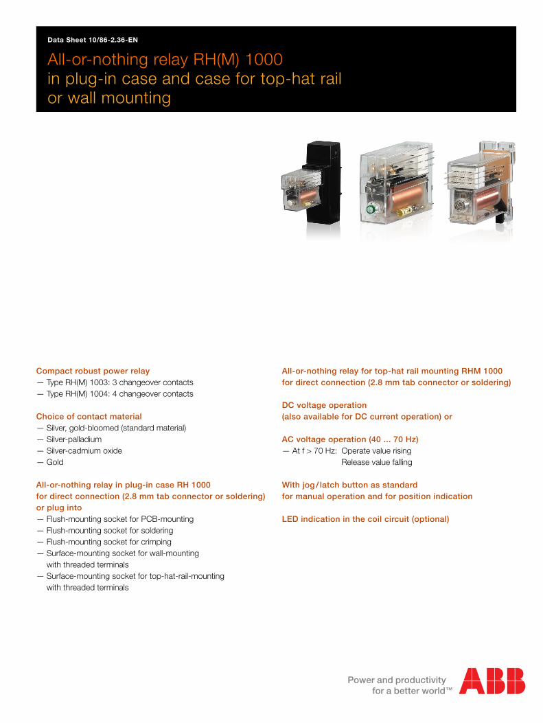
Circuit diagrams
All-or-nothing relay RH(M) 1003
Diagram 1All-or-nothing relay RH(M) 1003 for DCwith simple winding without auxiliary circuit
Diagram 2All-or-nothing relay RH(M) 1003 for DCwith simple winding and free-wheeling diodes, + on A1
Diagram 3All-or-nothing relay RH(M) 1003 for DCwith simple winding and free-wheeling diodes, + on A2
Diagram 4All-or-nothing relay RH(M) 1003 for DCwith simple winding, reverse-polarity protection, free-wheeling diode andLED indicator. * External connection to A2 not permissible!
Diagram 5All-or-nothing relay RH(M) 1003 for DCsimple winding with tap
Diagram 6All-or-nothing relay RH(M) 1003 for DCwith double winding without auxiliary circuit
Diagram 7All-or-nothing relay RH(M) 1003 for DC/AC* External connection to B1 not permissible!
Diagram 8All-or-nothing relay RH(M) 1003 for nominal voltage ≤ 24 V DC, 42/48 V ACwith LED indicator* External connection to B1 not permissible!!
Diagram 9All-or-nothing relay RH(M) 1003 for nominal voltage ≥ 48 V DC, 100 V ACwith LED indicator* External connection to B1 not permissible!
Diagram 10Flush-mounting socket for RH 1003with relay plugged in as example (grey)** Grounding connection obviated with flush-mounting socket for PCB
Diagram 11Surface-mounting socket for RH 1003with relay plugged in as example (grey)
RH(M) 1003 32 34
31
22 24
21
12 14
11
.
A2A1 B1
12003a
RH(M) 1003 32 34
31
22 24
21
12 14
11
12003b
+ A2A1 B1 –
RH(M) 1003 32 34
31
22 24
21
12 14
11
12003c
+A2A1 B1–
12003d
A1
RH(M) 1003 32 34
31
22 24
21
12 14
11B1 A2*+ –
RH(M) 1003 32 34
31
22 24
21
12 14
11
12003e
A2A1 B1
A2
RH(M) 1003 32 34
31
22 24
21
12 14
11A1
12003f
B1
12003g
A1
RH(M) 1003 32 34
31
22 24
21
12 14
11B1* A2+~–~
12003h
32 34
31
22 24
21
12 14
11A1
RH(M) 1003
B1* A2+~–~
12003i
A1
RH(M) 1003 32 34
31
22 24
21
12 14
11B1* A2+~–~
Flush-mounting socket 32 34 22 24 12 14
A2 112131
12003jen
**
B1A1A1
RH 1003 32 34
31
22 24
21
12 14
11B1* A2+~–~
Surface-mounting socket 32 34 22 24 12 14
A2B1 11213112003ken
A1A1
RH 1003 32 34
31
22 24
21
12 14
11B1* A2+~–~

04.01 Page 7 of 12
All-or-nothing relay RH(M) 1000in plug-in case and case for top-hat rail or wall-mounting 10/86-2.36 EN
Circuit diagrams
All-or-nothing relay RH(M) 1004
Diagram 12All-or-nothing relay RH(M) 1004 for DCwith simple winding without auxiliary circuit
Diagram 13All-or-nothing relay RH(M) 1004 for DCwith simple winding and free-wheeling diodes, + on A1
Diagram 14All-or-nothing relay RH(M) 1004 for DCwith simple winding and free-wheeling diodes, + on A2
Diagram 15All-or-nothing relay RH(M) 1004 for DCwith simple winding, reverse-polarity protection, free-wheeling diode andLED indicator * External connection to A2 not permissible!
Diagram 16All-or-nothing relay RH(M) 1004 for DCsimple winding with tap
Diagram 17All-or-nothing relay RH(M) 1004 for DCwith double winding without auxiliary circuit
Diagram 18All-or-nothing relay RH(M) 1004 for DC/AC* External connection to B1 not permissible!
Diagram 19All-or-nothing relay RH(M) 1004 for nominal voltage ≤ 24 V DC, 42/48 V ACwith LED indicator* External connection to B1 not permissible!
Diagram 20All-or-nothing relay RH(M) 1004 for nominal voltage ≥ 48 V DC, 100 V ACwith LED indicator* External connection to B1 not permissible!
Diagram 21Flush-mounting socket for RH 1004with relay plugged in as example (grey)** No grounding connection for flush-mounting socket for PCB’s
Diagram 22Surface-mounting socket (standard version) for RH 1004with relay plugged in as example (grey)
Diagram 23Surface-mounting socket (B1 on terminal 42) for RH 1004with relay plugged in as example (grey)
Diagram 24Surface-mounting socket (B1 on terminal A2) for RH 1004with relay plugged in as example (grey)
RH(M) 1004 44
41
32 34
31
22 24
21
12 14
11
42 .
A2A1 B1
12004a
RH(M) 1004 44
41
32 34
31
22 24
21
12 14
11
42 12004b
+ A2A1 B1 –
RH(M) 1004 44
41
32 34
31
22 24
21
12 14
11
42 12004c
+A2A1 B1–
12004d
A1
RH(M) 1004 44
41
32 34
31
22 24
21
12 14
11
42
B1 A2*+ –
RH(M) 1004 44
41
32 34
31
22 24
21
12 14
11
42 12004e
A2A1 B1
A2
RH(M) 1004 44
41
32 34
31
22 24
21
12 14
11
42
A1
12004f
B1
12004g
A1
RH(M) 1004 44
41
32 34
31
22 24
21
12 14
11
42
B1* A2+~–~
12004h
32 34
31
22 24
21
12 14
11
44
41
42
A1
RH(M) 1004
B1* A2+~–~
12004i
A1
RH(M) 1004 44
41
32 34
31
22 24
21
12 14
11
42
B1* A2+~–~
Flush-mounting socket 44 32 34 22 24 12 14
A2 41 112131
42 12004jen
**
B1A1
A1
RH 1004 44
41
32 34
31
22 24
21
12 14
11
42
B1* A2+~–~
44 32 34 22 24 12 14
A2 41 112131
42 12004ken
A1A1
RH 1004 44
41
32 34
31
22 24
21
12 14
11
42
B1* A2+~–~
Surface-mounting socket
44 32 34 22 24 12 14
A2 41 11213112004len
B1A1A1
RH 1004 44
41
32 34
31
22 24
21
12 14
11
42
B1 A2*+ –
Surface-mounting socket
Surface-mounting socket 44 32 34 22 24 12 14
A2 41 112131
42 12004men
A1A1
RH 1004 44
41
32 34
31
22 24
21
12 14
11
42
B1 A2*+ –

All-or-nothing relay RH(M) 1000in plug-in case and case for top-hat rail or wall-mounting 10/86-2.36 EN
Page 8 of 12
Dimensional drawings (dimensions in mm)
Drawing 4Top-hat rail
Drawing 8RH 1000 (side view)
Drawing 9Retainer clip for flush- and surface mounting sockets
Drawing 7Mounting bracket
Rear viewRH 1004
Rear viewRH 1003
Drawing 5RHM 1000 (side view)
Rear viewRHM 1004
Rear viewRHM 1003
Drawing 3Plug distributorfor RH(M) 1000
Drawing 2Plug-in sleevefor RH(M) 1000
Drawing 1Solder/plug pinon RH(M) 1000
Z-18361
2,8
7
1,6ø1,4
3,1
14
0,7
3,2
16
7,5
3527
Z-1
8371
7610
7,5
P
A
L
Z-18385
35
4,5
A2A1 B1
342414312111342414
7555
30
A2A1 B1
41
12
65
3 42
75
52Z
-183
75
ø1
16
10
5
38
254,5
28
Z-18369
Z-18360
66
73
52
15,3
M4T
32
29
24
14 24 443411 21 31 4112 22 32 42
A1 B1A2
24
52
14 24 3411 21 3112 22 32
A1 A2 B1

04.01 Page 9 of 12
All-or-nothing relay RH(M) 1000in plug-in case and case for top-hat rail or wall-mounting 10/86-2.36 EN
Dimensional drawings (dimensions in mm)
Drawing 14Adapter for flush-mounting socketfor mounting on top-hat rail or G-rail
Rear view offlush-mounting socketfor RH 1004
Rear view offlush-mounting socketfor RH 1003
Drawing 15Flush-mountingsocket (side view)
Drawing 4Top-hat rail
Drawing 18Surface-mounting socketwith snap fixingfor top-hat rails(side view)
Drawing 19Snap fixingfor top-hat rails(side view)
Drawing 20Surface-mountingsocket(side view)
Frontal view of thesurface-mounting socket
Drawing 4Top-hat rail
516
,51,5
32
Z-18372
15Drawing 16G-rail
7,5
3527
Z-1
8371
Z-1
8364
14 24 34
11 21 31
12 22 32
A1 A2 B1 A2A1 B1
12
11
14
22
21
24
32
34
31
42
44
41
7,5 7,5
7,57,5
7,5 7,5 7,5
1) 1)
6,25
6,25 44ø3,5 ø3,5
16,6
9,3
307,
8
20,2
4,3
24,72430
2430
15,3
52
23,5
49,5
18,8
15,3
3238
5259 49,5 12 12
5
ø3,5ø3,5
1x0,5
Z-18366
3,7
4,6
1,5x3
Z-18365
41,5
99
36 8
44
2221
41
A2
42 B1
A1
14 11 12
24 34 31 32
6
42
6
4,5
Z-18368
89 100
120
7,5
3527
Z-1
8371
Z-18367
13,3
3,7
41,5
14
44
2420
Z-1
8373
Drawing 12Soldering pin ofthe flush-mountingsocket for solderedconnection
Drawing 11Soldering pin ofthe flush-mountingsocket for PCB’s
Drawing 13Clip contactfor crimping

All-or-nothing relay RH(M) 1000in plug-in case and case for top-hat rail or wall-mounting 10/86-2.36 EN
Page 10 of 12
Ordering information for all available designsCatalog No. Code
Design V86236A-All-or-nothing relay in plug-in caseRH 1003 3 changeover contacts 1 0RH 1004 4 changeover contacts 2 0All-or-nothing relay, top-hat-rail- or wall-mountingRHM 1003 3 changeover contacts 3 0 0RHM 1004 4 changeover contacts 4 0 0Nominal coil voltage (DC)Simple winding 12 V DC 1 0
24 V DC 2 048 V DC 3 060 V DC 4 0
110/125 V DC 5 0220/250 V DC 6 0………. V DC 1) 5) 7 0 501
Auxiliary circuit without 0 0with free-wheeling diode (+ on A1) 2) 0 2with rev.polar.prot., free-wh.diode and LED (+ on A1) 2) 3) 4) 5) 0 3with free-wheeling diode (+ on A2) 2) 0 4
Winding with tap ………. V DC 1) 3) 5) 8 0 0 501Double winding ………. V DC 1) 3) 5) 9 0 0 501Nominal coil voltage (DC, AC)with reverse polarity protection, free-wheeling diode and protective circuitSimple winding 12 V DC 24 V AC 1 2
24 V DC 42/48 V AC 2 348 V DC 100 V AC 3 460 V DC 110/130 V AC 4 5
110/125 V DC 220/230/250 V AC 5 6220 V DC 6 7
………. V DC ………. V AC 1) 5) 7 7 501Auxiliary circuit without 1
with LED indicator 6Jog/latch buttonWith jog/latch button (standard design) 0Without jog/latch button 1Without jog/latch button, with PTB certificate 5) 7) 2Contact materialRH(M) 1003 Silver, gold-bloomed Ø 3,5 mm 1 0
Silver-cadmium oxide Ø 3,5 mm 2 0Silver-palladium Ø 3,5 mm 3 0Gold Ø 2,5 mm 4 0
RH(M) 1004 Silver, gold-bloomed Ø 3,5 mm 0 1Silver-cadmium oxide Ø 3,5 mm 0 2Silver-palladium Ø 3,5 mm 0 3Gold Ø 2,5 mm 0 4
1) Customer-specific within the realm of technical feasibility as per Catalog 86! State nominal voltage / nominal current of the coil. Possible nominal voltages: 5 to 250 V DC und 12 to 250 V AC2) Use only in existing installations. For new installations, use DC/AC version!3) Ancillary surface mounting: See footnote 3).4) Ancillary surface mounting: See footnote 4).5) Technical data may change compared to the standard design as per Catalog specifications.6) External connect. Not permitted due to intrnal assignment!7) This version will be phased out at the end of 2001!
Dim. draw.
81...912...20
51...912...20
1, 122, 134, 153, 145,166, 17
7, 188, 9, 12, 20
Circ. diagr.

04.01 Page 11 of 12
All-or-nothing relay RH(M) 1000in plug-in case and case for top-hat rail or wall-mounting 10/86-2.36 EN
Standard designs all-or-nothing relays RH(M) 1000Design Nominal voltage Catalog No.All-or-nothing relay RH 1003 12 V DC V86236A-1100010in plug-in case, 24 V DC V86236A-12000103 changeover contacts, 48 V DC V86236A-1300010contact material 60 V DC V86236A-1400010silver, gold-bloomed 110/125 V DC V86236A-1500010simple winding 220/250 V DC V86236A-1600010
12 V DC 24 V AC V86236A-112101024 V DC 42/48 V AC V86236A-123101048 V DC 100 V AC V86236A-134101060 V DC 110/130 V AC V86236A-1451010
110/125 V DC 220/250 V AC V86236A-1561010220 V DC V86236A-1671010
All-or-nothing relay RH 1004 12 V DC V86236A-2100001in plug-in case, 24 V DC V86236A-22000014 changeover contacts, 48 V DC V86236A-2300001contact material 60 V DC V86236A-2400001silver, gold-bloomed 110/125 V DC V86236A-2500001simple winding 220/250 V DC V86236A-2600001simple winding 12 V DC 24 V AC V86236A-2121001
24 V DC 42/48 V AC V86236A-223100148 V DC 100 V AC V86236A-234100160 V DC 110/130 V AC V86236A-2451001
110/125 V DC 220/250 V AC V86236A-2561001220 V DC V86236A-2671001
All-or-nothing relay RHM 1003 12 V DC V86236A-3100010top-hat-rail- or 24 V DC V86236A-3200010Wall-mounting 48 V DC V86236A-33000103 Changeover contacts, 60 V DC V86236A-3400010contact material 110/125 V DC V86236A-3500010silver, gold-bloomed, 220/250 V DC V86236A-3600010simple winding 12 V DC 24 V AC V86236A-3121010
24 V DC 42/48 V AC V86236A-323101048 V DC 100 V AC V86236A-334101060 V DC 110/130 V AC V86236A-3451010
110/125 V DC 220/250 V AC V86236A-3561010220 V DC V86236A-3671010
All-or-nothing relay RHM 1004 12 V DC V86236A-4100001top-hat-rail- or 24 V DC V86236A-4200001wall-mounting 48 V DC V86236A-43000014 changeover contacts, 60 V DC V86236A-4400001contact material 110/125 V DC V86236A-4500001silver, gold-bloomed, 220/250 V DC V86236A-4600001simple winding 12 V DC 24 V AC V86236A-4121001
24 V DC 42/48 V AC V86236A-423100148 V DC 100 V AC V86236A-434100160 V DC 110/130 V AC V86236A-4451001
110/125 V DC 220/250 V AC V86236A-4561001220 V DC V86236A-4671001
Dim. draw.1 81 81 81 81 81 87 87 87 87 87 87 812 812 812 812 812 812 818 818 818 818 818 818 81 51 51 51 51 51 57 57 57 57 57 57 512 512 512 512 512 512 518 518 518 518 518 518 5
Circ. diagr.

All-or-nothing relay RH(M) 1000in plug-in case and case for top-hat rail or wall-mounting 10/86-2.36 EN
ABB Automation Products GmbHHoeseler Platz 2D-42579 HeiligenhausPhone +49(0)20 56-12 51 81Fax +49(0)20 56-12 50 81http://www.abb.com
Technische Änderungen vorbehalten.Printed in the Fed. Rep. of Germany
10/86-2.36 EN 04.01
Special designs RH(M) 1000Design Nominal voltage Catalog No. CodeRH 1003 for GEAMATIC 24 V DC 5) V86236A-1800120 510RHM 1003 for GEAMATIC 24 V DC 5) V86236A-3800020 510RH 1004 for Protronic P 24 V DC 5) V86236A-2702002 511RHM 1004 for Protronic P 24 V DC 5) V86236A-4702002 511
Accessories for all-or-nothing relays RH 1000Design Catalog No.Angle bracket (25 per pack) V86211A-0305000Retaining clip for plug-in case (25 per pack) V86211A-0404000Flush-mounting case (with retaining clip)for RH 1003 for PCBs V86210A-1500000(all designs) for soldered connections V86210A-2500000
for crimping V86210A-3500000for RH 1004 for PCBs V86210A-1600000(all designs) for soldered connections V86210A-2600000
for crimping V86210A-3600000Adapter for mounting flush-mounting case on V86211A-7000000top-hat rails or G-type railsSurface-mounting case with threaded terminal ends (with retaining clip)für RH 1003 all designs V86210A-4050000für RH 1004 standard design V86210A-4060000für RH 1004 B1 on terminal 42 3) V86210A-5060000für RH 1004 B1 on terminal A2 4) V86210A-8060000Surface-mounting case with threaded terminal ends andsnap-on fixing for top-hat rail (with retaining clip)für RH1003 all designs V86210A-6050000für RH1004 standard design V86210A-6060000für RH1004 B1 on terminal 42 3) V86210A-7060000für RH1004 B1 on terminal A2 4) V86210A-9060000Spare caps for surface-mounting case (2 per pack) V86211A-8800000
Snap-on fixing for top-hat rail V86211A-9800000(for retrofitting to surface-mounting cases)Top-hat rail EN 50022-35x7.5 (2000 mm long) V86299A-1100000
Accessories for all-or-nothing relays RHM 1000Description Catalog No.Top-hat rail EN 50022-35 x 7.5 (2000 mm long) V86299A-1100000
3) Important: The 4th changeover contact is connected to the terminal as make contact only4) Relay coil connection B1 is taken to terminal A25) Technical data may change compared to the standard design as per Catalog specifications6) Coil begin: A1 / coil end: B1 / center tapning point: A2
Dim. draw.6) 86) 512 812 5
Dim. draw.79
10 1510 1510 1521 1521 1521 15
14
11 2022 2023 2024 20
11 1822 1823 1824 18
19
4
Dim. draw.4
Circ. diagr.
Circ. diagr.


10/8
6-2.
36-E
N 0
1.20
11
Contact us
NoteWe reserve the right to make technical changes or modify the contents of this document without prior notice. With regard to purchase orders, the agreed particulars shall prevail. ABB does not accept any responsibility whatsoever for potential errors or possible lack of information in this document.
We reserve all rights in this document and in the subject matter and illustrations contained therein. Any reproduction, disclosure to third parties or utilization of its contents – in whole or in parts – is forbidden without prior written consent of ABB.
Copyright© 2011 ABBAll rights reserved
3KDE460000R1001
ABB Automation Products GmbHProcess AutomationBorsigstr. 263755 AlzenauGermanyTel: +49 551 905-534Fax: +49 551 905-555
www.abb.com