Embed Size (px)
Citation preview
Lf I Data Link Processor (DLP)NI Operational Test and
Evaluation/I nteg rationTest Plan
DEC 1989~
Norman W. WattsNoel A. Doucett (SEI-TCO) W
December 1989
DOT/FAA/CT-TN89/32
This document is available to the U.S. publicthrough the National Technical InformationService, Springfield, Virginia 22181.
/ - - ' I 7_/ !- -." '7 " -.7 - ...
US Department of Tronsptooftton
Ftdelail Avkion Administreation
Technical CenterAtlantic City International Airporl N J 08405
89 78 067
NOTICE
This document is disseminated under the sponsorshipof the U.S. Department of Transportation in the interest of
information exchange. The United States Governmentassumes no liability for the contents or use thereof.
The United States Government does not endorse
products or manufacturers. Trade or manufacturers'
names appear herein solely because they are considered
essential to the objective of this report.
Technical Report Documentasiot Fugs1. Reeprt No. 2. Goernient Accesson No. 3. Recipint's Ca elog No.
DOT/FAA/CT-TN89/32
4. T~tl and Sbwie 5. Report O.,
DATA LINK PROCESSOR (DLP) OPERATIONAL TEST December 1989
AND EVALUATION/INTEGRATION TEST PLAN 6 P Orgoaation Code
8. Perfotmng O'gw'.tzton Reort No.
7. Author'*)
Norman W. Watts and Noel A. Doucett (SEI-TCO) DOT/'FAA/CT-TN89/329. Perforing Orjn.zoton Name mqd Address 10. Work Unit No. (TRAIS)
Federal Aviation Administration
Technical Center 11. Conr,.or Gioo N..
Atlantic City International Airport, New Jersey 0840513. Type of Repot end Peiod Co,,rod
12. Sponsoring Agency Nome and Address
U.S. Department of Transportation Technical Note
Federal Aviation Administration
Technical Center 14. Snee,ng Agency Cde
Atlantic City International Airport, Ne Jersey 08405Is. Supplementay Notes
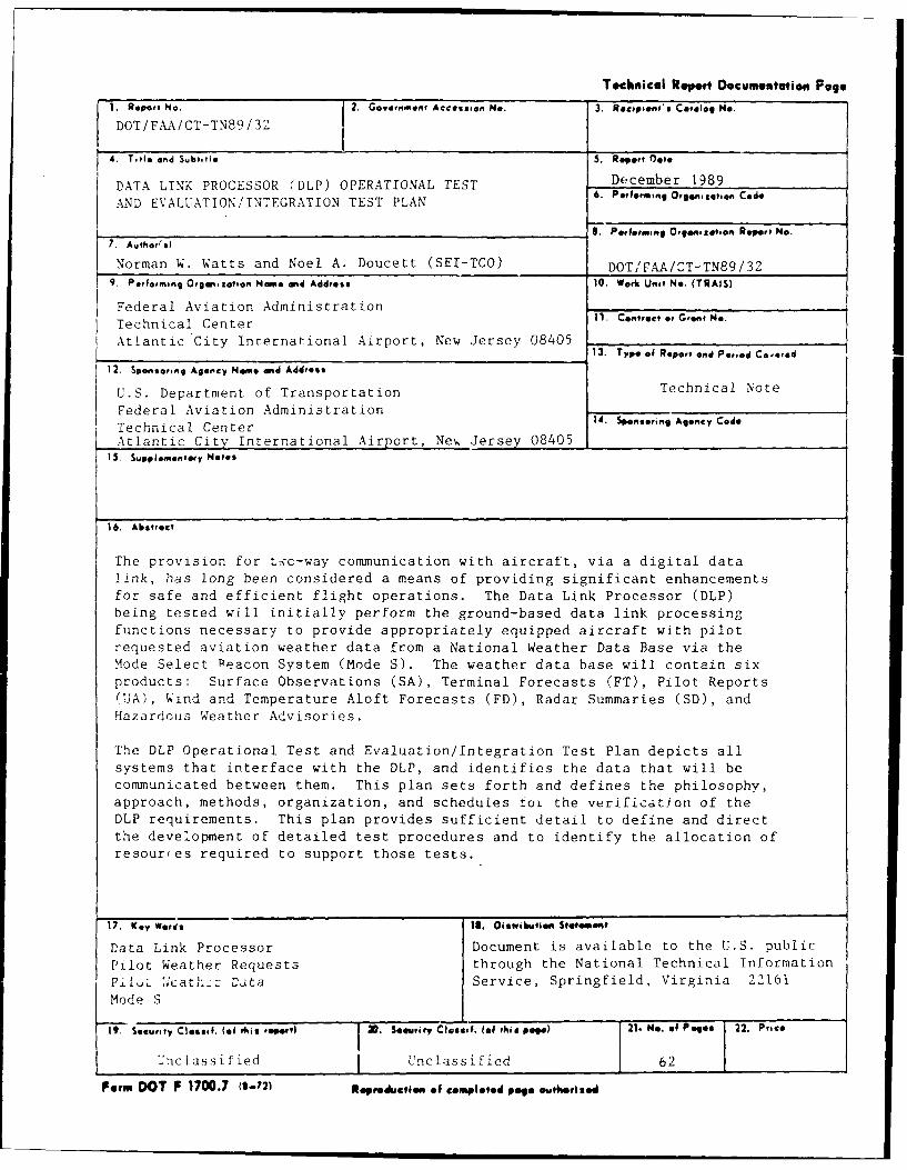
16. Abstrect
The provision for t'c-way communication with aircraft, via a digital data
link, has long been considered a means of providing significant enhancements
for safe and efficient flight operations. The Data Link Processor (DLP)
being tested will initially perform the ground-based data link processing
functions necessary to provide appropriately equipped aircraft with pilot
requested aviation weather data from a National Weather Data Base via the
Mode Select Peacon System (Mode S). The weather data base will contain six
products: Surface Observations (SA), Terminal Forecasts (FT), Pilot Reports
(UA), Wind and Temperature Aloft Forecasts (FD), Radar Summaries (SD), and
Hazardous Weather Advisories.
The DLP Operational Test and Evaluation/Integration Test Plan depicts all
systems that interface with the DLP, and identifies the data that will be
communicated between them. This plan sets forth and defines the philosophy,
approach, methods, organization, and schedules tot the verification of the
DLP requirements. This plan provides sufficient detail to define and direct
the development of detailed test procedures and to identify the allocation of
resources required to support those tests.
17. Key Werds I1. O6s0ttrihuti Stf oneem t
Data Link Processor Document is available to the U.S. public
Pilot Weather Requests through the National Technical Information
PJll :';at,'_: Data Service, Springfield, Virginia 22161
Mode S
19. Security Closeld. (06 this trl)ut 20. Siseuriy dlsi. (of this Pogo) 21. me. of Paes 22. Price
Unclassified I Unclassified 62
Form DOT F 1700.7 (2-72) Ropeodtuffa. of completed Po. owtheOrlsd
TABLE OF CONTENTS
Page
EXECUTIVE SUMMARY v
1. INTRODUCTION 1
1.1 Scope 21.2 Purpose 2
2. APPLICABLE DOCUMENTS 2
2.1 Government Documents 2
3. DLP OPERATIONAL AND INTEGRATION TEST PLAN OVERVIEW 5
3.1 Test and Evaluation Philosophy 53.2 Integration Test Plan and Approach 5
4. DLP OPERATIONAL AND INTEGRATION TEST PLAN VERIFICATION CONTROL 8
4.1 TVRTM 8
5. DLP OPERATIONAL AND INTEGRATION TEST CATEGORIES 8
5.1 Test Category 01 Interface Requirements 95.2 Test Category 02 Basic Systems Operations 145.3 Test Category 03 Startup, Shutdown and Restart 185.4 Test Category 04 Reconfiguration 195.5 Test Category 05 Diagnostics 205.6 Test Categoiy 06 Security 22
6. DLP TESTING ORGANIZATIONAL ROLES AND RESPONSIBILITIES 22
6.1 DLP Test M ., ment Group 226.2 DLP Test Sur. ,--- Group 216.3 DLP Integrat_ Test Management 246.4 DLP Testing Resource Requirements 26
7. DLP TEST DOCUMENTATION REQUIREMENTS AND CONTROL 26
7.1 Documentation 267.2 Reviews 29
8. DLP T&E SCHEDULES 30
8.1 DLP Major Activities Schedule 31
il).
TABLE OF CONTENTS (Continued)
Page
9. ABBREVIATIONS AND ACRONYMS 32
APPENDIXES
A - TVRTM
B - Sample Forms for DLP Testing
LIST OF ILLUSTRATIONS
Figure Page
2-1 DLP Integration Test Plan Documentation Tree 4
3.2.i-1 Data Link Processor System End State Configuration 6
3.2.1-2 Data Link Processor System Test Configuration 7
5.2.1-1 DLP Test Block Diagram 23
LIST OF TABLES
Table Page
8.1-1 DLP Major Activities Schedule 31
iv
EXECUTIVE SUMMARY
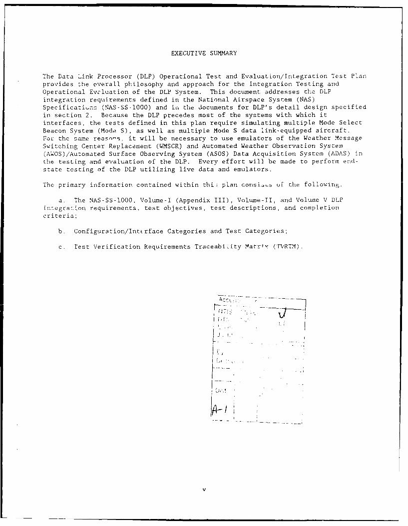
The Data Link Processor (DLP) Operational Test and Evaluation/Integration Test Plan
provides the overall philosophy and approach for the Integration Testing andOperational Evaluation of the DLP System. This document addresses the DLP
integration requirements defined in the National Airspace System (NAS)Specificatiunz (NAS-SS-1000) and iLL the documents for DLP's detail design specifiedin section 2. Because the DLP precedes most of the systems with which itinterfaces, the tests defined in this plan require simulating multiple Mode SelectBeacon System (Mode S), as well as multiple Mode S data link-equipped aircraft.For the same reasons, it will be necessary to use emulators of the Weather MessageSwitching Center Replacement (WMSCR) and Automated Weather Observation System
(AWOS)/Automated Surface Observing System (ASOS) Data Acquisition System (ADAS) inthe testing and evaluation of the DLP. Every effort will be made to perform end-
state testing of the DLP utilizing live data and emulators.
The primary information contained within thi; plan consi.,b of the following.
a. The NAS-SS-1000, Volume-I (Appendix III), Volume-II, and Volume V DLPintegration requirements, test objectives, test descriptions, and completion
criteria;
b. Configuration/Intcrface Categories and Test Categories;
c. Test Verification Requirements TraceabiLity Matriv (FVRTM).
V
1. INTRODUCTION.
The provision for two-way communication with aircraft, via a digital data link, haslong been considered a means of providing significant enhancements for safe andefficient flight operations and reducing controller workload. The Data LinkProcessor (DLP) being tested will initially perform the ground-based data linkprocessing functions necessary to provide appropriately equipped aircraft withpilot requested aviation weather data from a National Weather Data Base via theMode Select Beacon System (Mode S) data link. The weather data base will containi products: Surface Observations (SA), Terminal Forecasts (FT), Pilot Reports(UA), Wind and Temperature Aloft Forecasts (FD), Radar Summaries (SD), andHazardous Weather Advisories. The DLIP is being implemented in multiple phases; aninitial state (build-one) DLP system is being tested, a build-two system thatincorporates additional weather services and an initial set of ATC commands. Thebuild-three system adds additional ATC services and finally, the end-state DLPsystem adds more weather services. The initial state will include a subset of thecontemplated end-state requirements as given in the NAS System RequirementsSpecification (NAS-SR-1000) and the NAS System Specification (NAS-SS-1000). Thisdocument addresses exclusively the requirements of the initial DLP system as givenin the Data Link Processor Software Segment Specification (7Ah L-OR-2802a) and theData Link Processor Hardware Specification (FAA-E-2794a). In the event of aconflict, FAA-OR-2802a shall take precedence.
A major source if tLhe National Aviation Weather S-rvice data is currently theWeather Message Switching Center (WMSC) in Kansas City, MO. Under the NationalAirspace System (NAS) modernization plan, the WMSC will be replaccd by two WMSCReplacement (WMSCR) systems; one located in Salt Lake City, UT, and the otherlocated in Atlanta, GA. The WMSCR is currently scheduled to be operational in1992. Automated Weather Observation System (AWOS) and Automated Surface ObservingSystem (ASOS) will provide instantaneous surface observation type informationaut-matisally at their locations. The AWOS Data Acquisition System (ADAS) willconcentrate minute-by-minuLe information from up to 137 AWOS/ASOS sites fortransmission to one DLP. The ADAS is currently scheduled to be operational in1992.
The Maintenance Processor Subsystem (MPS) will monitor, using polled requests,DLP's operational status and modes in real time. A non-end state version C.f MPS iscurrently available.
The Mode S is being developed under the auspices of the Federal AviationAdministration (FAA) as an upgrade to the present Air Traffic Control Radar BeaconSystem (ATCRBS), and will ultimately provide improved surveillance capabilitycoupled with integrated ground-air-ground data links for air traffic control (ATC)and non-ATC communications. The DLP is currently scheduled for delivery andsubsequent integration, and operational evaluation testing at the FAA TechnicalCenter before an operational Mode S systems will be available. Because theoperational DLP must interface with up to 32 active Mode S systems, it will beldu"csary to use some means of simulating multiple Mode S sites. Similarly, theDLP must be capable of servicing up to 2000 data link-equipped aircraft. Because.at most, two prototype Airborne Data Link Processors (ADLP)/Avionics systems willbe available at the FAA Technical Center in the integration testing time frame, itis imperative to simulate multiple data link-equipped aircraft.
m m m | |
MITRE Corporation is under contract to supply WMSCR and ADAS emulators for use inDLP Integration Testing and Operational Evaluation at the FAA Technical Center.ACD-320 will provide a Data Link and Transponder Analysis System (DATAS) forsimulation of multiple Mode S sensors and more than 2000 Mode S data link-equippedaircraft for operational and functional integration testing of the DLP. ACD-320will also provide at least two prototype ADLP/Avionics systems, including Mode Stransponders. An in-flight operational demonstration of the DLP/Mode S/ADLP end-to-end performance testing will be conducted when a Mode-S sensor becomes availableat the FAA Technical Center.
1.1 SCOPE.
This plan defines the test requirements which must be satisfied to assure that 'heDLP meets the minimum acceptable System Level Test and Evaluation (SLT&E) and theIntegration Test and Evaluation (IT&E) requirements identified in the DLP TestVerification Requirements Traceability Matrix (TVKTM) presented in appondix A ofthis 0-ctiment. This plan shall be reviewed and approve, by the FAA prior to the
preparation of detailed integration test procedures.
1.2 PURPOSE.
The purpose of this plan is to define the approach, methods, resources, andschedules including DLP's error detection in all received messages, frames, andpackets from interfacing systems, and protocol levels through the use of externalsimulators and emulators, for the verification of the DLP requirements. Detaileddiscussion of the test methods associated with operational and procedural typefunctions, such as system startup/restart, system update, on-line and off-linereports generation, etc., will be contained in the test procedures. This planprovides sufficient detail to define and direct the development of detailed testprocedures and to identify the allocation of resources required to support thistest. Detailed test procedures shall be developed under a separate document in
accordance with FAA-STD-024a.
2. APPLICABLE DOCUMENTS.
2.1 GOVERNMENT DOCUMENTS.
2.1.1 FAA Specifications.
NAS PLAN NAS Initial State Project
NAS-DD-O000 NAS Level I Design
NAS-SR-IO00 NAS System Requirements Specification
NAS-SS-1O00 NAS System Specification
FAA-OR-2802a Data Link Processor Software Segment Specification
FAA-E-2794a Data Link Processor Hardware Specification
2
FAA-W48-094 Data Link Processor Weather Data Processing and Retrieval
Requirements
FAA-RD-80-14A The Mode Select Surveillance and Communications, ATC and Non-ATC
Link Protocols, and Message Formats
NAS-IR-25072503 WMSCR/DLP Interface Requirements Document
NAS-IR-25082503 DLP/ADAS Interface Requirements Document
NAS-IR-43020001 NADIN/X.25 Packet Mode Users Interface Requirements Document
NAS-IR-51030002 Maintenance Processor Subsystem to Automation Subsystems,Interface Requirements Document
NAS-IR-92020000 Coded Time Source Interface Requirements Document (Draft)
NAS-IC-25082503 DLP to ADAS Interface Control Document
NAS-IC-25036403 DLP to WMSC Interface Control Document
NAS-IC-25035103 DLP to MPS Interface Control Document
NAS-IC-25072503 DLP to WMSCR Interface Control Document
NAS-IC-34062503 DLP to Mode S Interface Control Document
2.1.2 FAA Standards.
FAA-STD-024a "Preparation of Test and Evaluation Documentation"
2.1.3 Occupational Safety and Health Administration (OSHA) Regulations.
nqHA-CwR-21 CFR 1910 OSHA Safety and Health Standards
2.1,4 Other FAA Documentation.
FAA Ord 1800.8E NAS Configuration Management
FAA Ord 1810.4b £i NAS Test and Evaluation Program
FAA Ord 1600.54b FAA Automated Information System Security Handbook
NAS-MD-110 Test and Evaluation Terms and Definitions for Lhe NAS
NAS-MD-790 Maintenance Processor Subsystem to Remote Monitoring Subsystemsand Remote Monitoring Subsystem Concentrators, Interface ControlDocument
DLP MTP DLP Master Test Plan
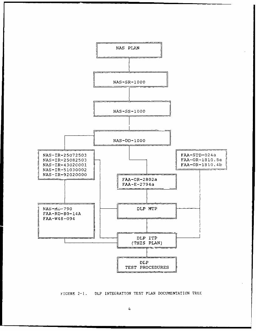
The documentation hierarchy and interrelationships are depicted in figure 2-1.
NAS PLAN
NAS-SR-1000
NAS-SS-1000
NAS-DD-1000
NAS-IR-25072503 [ FAA-STD-024aNAS-IR-25082503 FAA-OR-1810.8eNAS-IR-43020001 FAA-OR-1810.4bNAS-IR-51030002 - _
NAS-IR-92020000 F - 2FAA-OR-2802a
FAA-E-2794a
NAS-Mo-790 DLP MTPFAA-RD-80-14A
FAA-W48-094 L _ _ I_ _ _ _
I _________L.-
TEST PROCEDURES
FIGURE 2-1. DLP INTEGRATION TEST PLAN DOCUMENTATION TREE
4
3. DLP OPERATIONAL AND INTEGRATION TEST PLAN OVERVIEW.
3.1 TEST ANP ALUATION PHILOSOPHY.
The intpbration and operational evaluation testing conducted at the FAA TechnicalCent will verify the system level integration requirements (e.g., performance.functional, and interface characteristies) of the DLP system. This plai and
associated test procedures will accomplish the following:
a. Verify the DLP's capability to properly interface and function witinassociated equipment,
b. Provide early detection of interface design problems.
C. Ensure that operationally effective and suitable systems are impbere:tinto the NAS.
2.2 LNTEGRATION TEST PLAN AND APPROACH.
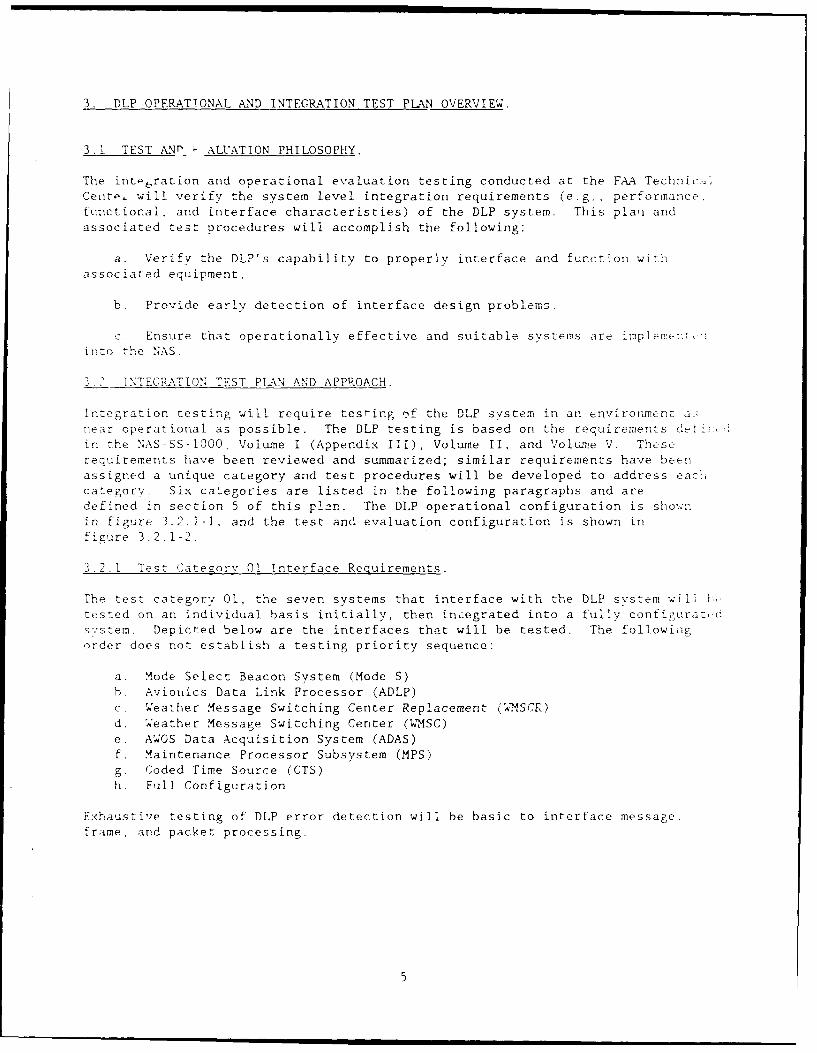
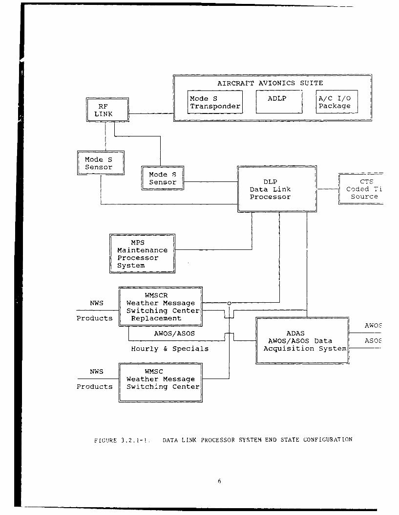
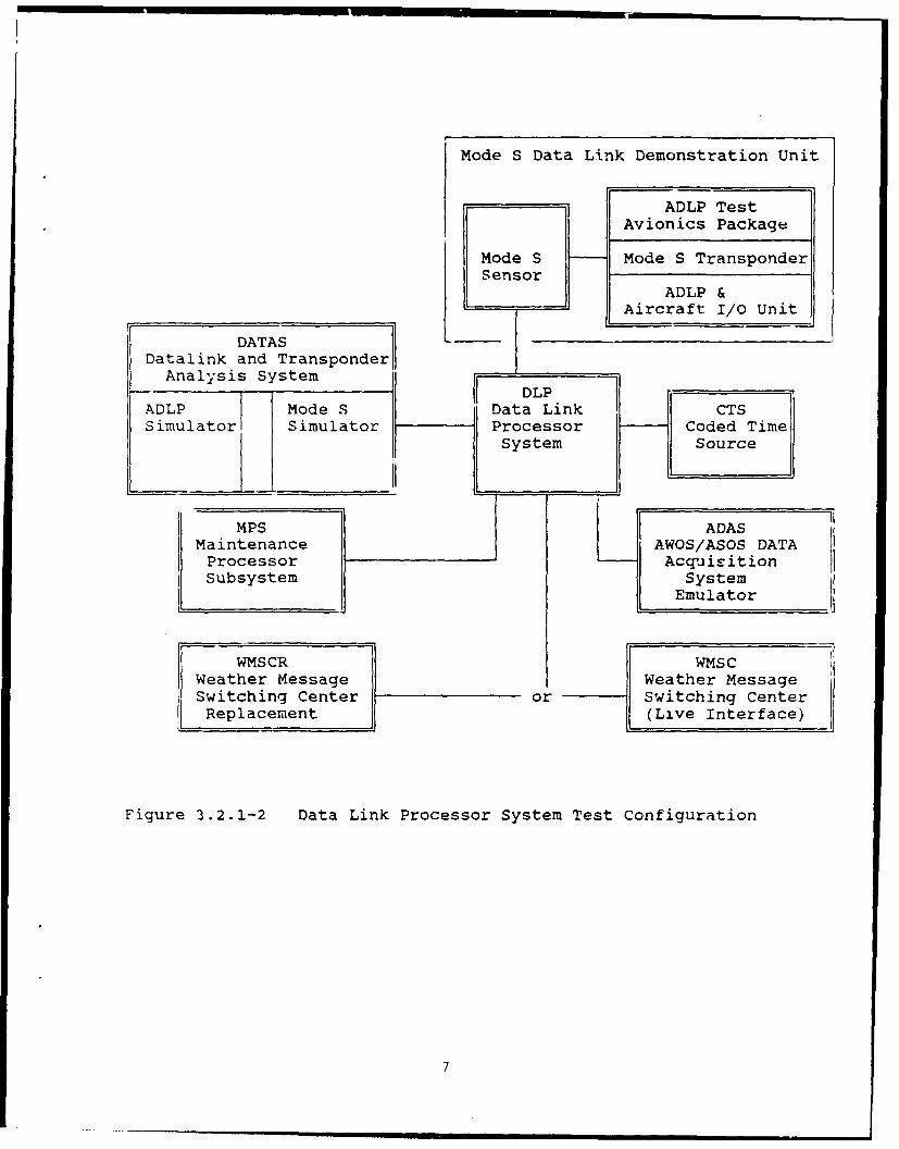
Integration testing will require testing -,f the DLP system in an envirorment ..near operational as possible. The DLP testing is based on the requirements d.:-in the NAS-SS-1000, Volume I (Appendix III), Volume II, and Volwne V. Theserequirements have been reviewed and summarized; similar requirements have beenassigned a unique category and test procedures will be developed to address eachcategory. Six catego-ies are listed in the following paragraphs and aredefined in section 5 of this plan. The DLP operational configuration is shownin figure 3.2.1-1, and the test and evaluation configuration is shown infigure 3.2.1-2.
3.2.1 Test Category 01 Interface Requirements.
The test category 01, the seven systems that interface with the DLP system willtested on an individual basis initially, then incegrated into a fully configura,,'.sy'stem. Depicted below are the interfaces that will be tested. The followiiigorder does not establish a testing priority sequence:
a. Mode Select Beacon System (Mode S)h. Aviouics Data Link Processor (ADLP)
c. Weather Message Switching Center Replacement (WSCR)
d. eather Message Switching Center (WMSC)
e. AWOS Data Acquisition System (ADAS)
f. Maintenance Processor Subsystem (MPS)
g. Coded Time Source (CTS)
h. Full Configuration
Exhaustive testing of DLP error detection will be basic to inrerface message,
frame, and packet processing.
5
AIRCRAFT AVIONICS SUITE
Mode S ADLP A/C 1/0RF Transponder Package
LINK
Mode S
- Mode S
Sensor DLP CTSData Link Coded TiProcessor Source
MPSMaintenanceProcessor
System
WMSCRNWS Weather Message o
Switching CenterProducts Replacement
AWOSAWOS/ASOS ADAS
AWOS/ASOS Data ASOSHourly & Specials Acquisition System
NWS WMSCWeather Message
Products Switching Center
FIGURE 3.2.1-!. DATA LINK PROCESSOR SYSTEM END STATE CONFIGURATION
6
Mode S Data Link Demonstration Unit
ADLP TestAvionics Package
Mode S Mode S TransponderSensor
ADLP &
Aircraft I/O Unit
DATASDatalink and Transponder
Analysis System _ _
- 1 DLPADLP Mode S Data Link CTSSimulator Simulator Processor Coded Time
System Source
MPS ADASMaintenance AWOS/ASOS DATAProcessor AcquisitionSubsystem System
Emulator
WMSCR WMSCWeather Message Weather MessageSwitching Center or Switching Center
Replacement (Live Interface)
Figure 3.2.1-2 Data Link Processor System Test Configuration
7
3.2.2 Test Category 02 Basic Systems Operations.
The testing that will be conducted within test category 02 shall be based on thesuccessful completion of tests conducted in test category 01. Within category 02,all functional and operational evaluation functions will be exercised at maximumcapacity levels to ensure all systems satisfy all performance specifications. Thistest will simultaneously test all of the DLP's interfacing systems. Succdssfulcompletion of this test will demonstrate that the DLP can function and operate inthe NAS environment.
3.2.3 Test Catezory 03 Startup, Shutdown, and Restart.
The testing within test category 03, demonstrates the DLP can perform the indicatedfunctions, and enable personnel to follow operational procedures typically used in
an actual operational environment by site personnel.
3.2.4 Test Category 04 Reconfiguration.
Test category 04 will be conducted to ensure that changes in the operationalconfiguration can be made by operational personnel.
3.2.5 Test Category 05 Diagnostics.
Testing conducted in this category will enable the operations personnel to evaluate
the integrity of the alarms, alerts, and messages produced when errors are enteredduring testing.
3.2.6 Test Category 06 Security.
These tests will confirm that protective measures have been implemented.
4. DLP OPERATIONAL AND INTEGRATION TEST PLAN VERIFICATION CONTROL.
4.1 TVRTM.
The DLP Integration Test Plan TVRTM contained in appendix A was developed ir.accordance with FAA-STD-024a, appendix IV. The TVRTM lists the applicablerequirements from the NAS-SS-1000, Volume I (Appendix III), Volume II, and Volume VNAS System Specification. Each of these requirements will be verified by theidentified methods, i.e., test and/or demonstration, through the successfulcompletion of the detailed integration test procedures.
5. DLP OPERATIONAL AND INTEGRATION TEST CATEGORIES.
The DLP operational and integration testing consists of one configuration and sixtest categories. This section will define each category identified in section 3.
8
5.1 TEST CATEGORY 01 INTERFACE REQUIREMENTS.
5.1.1 Mode S.
These tests will verify the requirements related to the DLP interface with theMode S. All DLP integration testing with the Mode S system will be made usingDATAS test scenarios. DATAS will satisfy all communication protocols of Mode S,i.e., any Mode S protocol directed responses to communications with the DLP willautomatically and routinely be satisfied by DATAS. Each DATAS test scenario willbe an input file to DATAS consisting of (1) communication messages including timeof message transmission to the DLP, and (2) flags to direct and/or influence Mode S
responses to messages received from the DLP.
5.1.1.1 Mode S Communications Protocol Testing.
DATAS will read a DLP communications protocol test scenario that exercises allmeasurable/testable X.25 Link Access Procedures Balance (LAPB) intercommunications
protocol requirements. Because the DLP uses digital microprocessors to execute allline driver communications protocol functions, this test scenario will simulatefunctions, such as communications line dropouts, timeouts, and failures to verifyDLI's communications protocol processing.
5.1.1.2 Mode S Testing.
The DATAS test scenario associated with Mode S interface testing will verify thatevery Mode S/DLP frame is processed and/or received by the DLP. The frames to be
tested are the following:
a. DLP to Mode S Frames
i. Standard Uplink2. Extended Length Message (ELM) Uplink3. Request for Downlink Data*4. Message Cancellation Request*
5. Data Link Capability Request6. Request for Aircraft State7. Request for Aircraft Position*8. Test Message
9. ATCRBS ID Request
*frames not tested in build-one
b. Mode S to DLP Frames
1. Message Rejection/Delay Notice2. Message Rejection Delay Notice with Sensor (Identifications (ID))
3. Sensor Recovery Notice4. Uplink Delivery Notice5. Pilot Downlink6. Pilot Downlink with Position
7. Broadcast Downlink*8. Broadcast Downlink with Position*9. ELM Downlink*
10. ELM Downlink with Position*
il. Data Link Capability
9
12. Aircraft State13. Aircraft Position14. Track Drop15. Test Response Message
16. Ground Initiated Downlink17. Ground Initiated Downlink with Position
18. ATCRBS ID Code**19. Track Alert Message**
*frames not processed, but archived by DLP**frames not tested in build-one
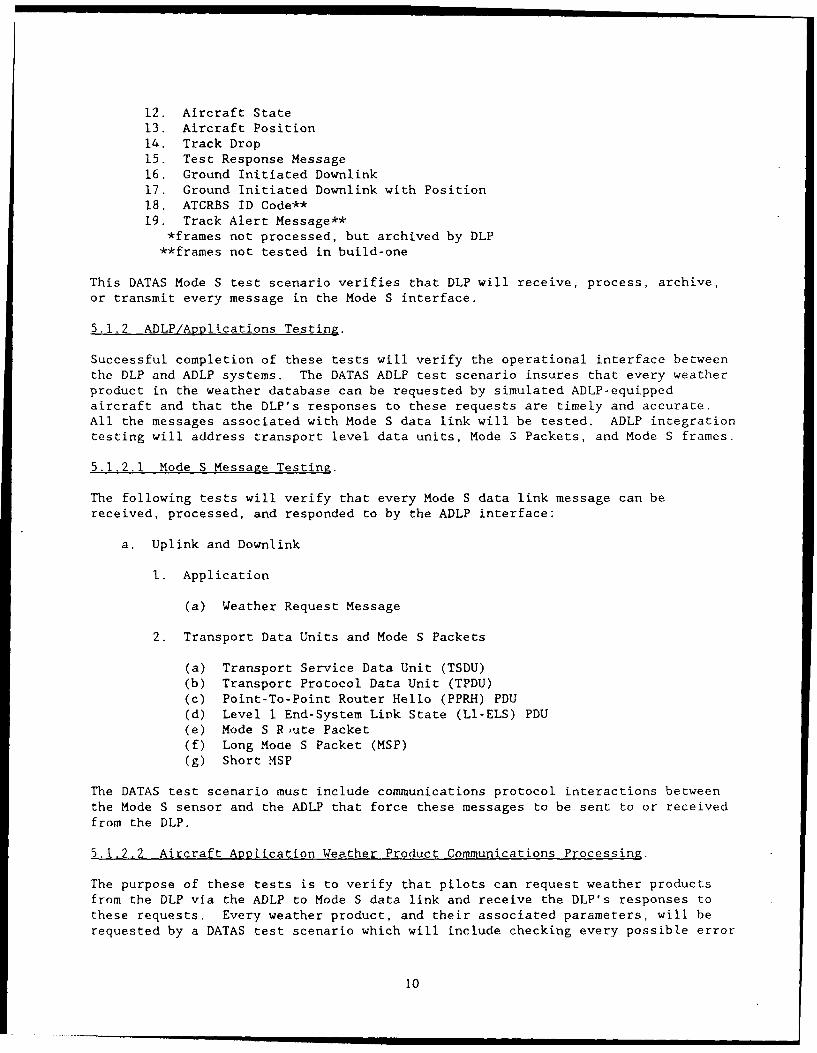
This DATAS Mode S test scenario verifies that DLP will receive, process, archive,
or transmit every message in the Mode S interface.
5.1.2 ADLP/Applications Testing.
Successful completion of these tests will verify the operational interface betweenthe DLP and ADLP systems. The DATAS ADLP test scenario insures that every weatherproduct in the weather database can be requested by simulated ADLP-equippedaircraft and that the DLP's responses to these requests are timely and accurate.All the messages associated with Mode S data link will be tested. ADLP integrationtesting will address transport level data units, Mode S Packets, and Mode S frames.
5.1.2.1 Mode S Message Testing.
The following tests will verify that every Mode S data link message can bereceived, processed, and responded to by the ADLP interface:
a. Uplink and Downlink
I. Application
(a) Weather Request Message
2. Transport Data Units and Mode S Packets
(a) Transport Service Data Unit (TSDU)(b) Transport Protocol Data Unit (TPDU)(c) Point-To-Point Router Hello (PPRH) PDU(d) Level 1 End-System Link State (LI-ELS) PDU(e) Mode S R'ute Packet(f) Long Moce S Packet (MSP)(g) Short MSP
The DATAS test scenario must include communications protocol interactions betweenthe Mode S sensor and the ADLP that force these messages to be sent to or received
from the DLP.
5.1.2,2 Aircraft Application Weather Product Communications Processing.
The purpose of these tests is to verify that pilots can request weather productsfrom the DLP via the ADLP to Mode S data link and receive the DLP's responses tothese requests. Every weather product, and their associated parameters, will berequested by a DATAS test scenario which will include checking every possible error
10
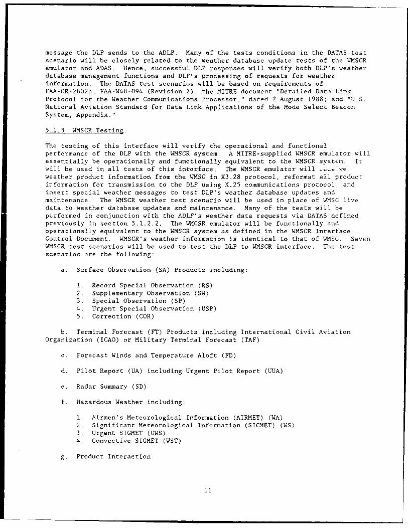
message the DLP sends to the ADLP. Many of the tests conditions in the DATAS testscenario will be closely related to the weather database update tests of the WMSCRemulator and ADAS. Hence, successful DLP responses will verify both DLP's weatherdatabase management functions and DLP's processing of requests for weatherinformation. The DATAS test scenarios will be based on requirements ofFAA-OR-2802a, FAA-W48-094 (Revision 2), the MITRE document "Detailed Data LinkProtocol for the Weather Communications Processor," dated 2 August 1988; and "U.S.National Aviation Standard for Data Link Applications of the Mode Select BeaconSystem, Appendix."
5.1.3 WMSCR Testing.
The testing of this interface will verify the operational and functionalperformance of the DLP with the WMSCR system. A MITRE-supplied WMSCR emulator willessentially be operationally and functionally equivalent to the WMSCR system. Itwill be used in all tests of this interface. the WMSCR emulator will £ec=veweather product information from the WMSC in X3.28 protocol, reformat all productirformation for transmission to the DLP using X.25 communications protocol, andinsert special weather messages to test DLP's weather database updates andmaintenance. The WMSCR weather test scenario will be used in place of WMSC livedata to weather database updates and maintenance. Many of the tests will bept-rformed in conjunction with the ADLP's weather data requests via DATAS definedpreviously in section 5.1.2.2. The WMCSR emulator will be functionally andoperationally equivalent to the WMSCR system as defined in the WMSCR InterfaceControl Document. WMSCR's weather information is identical to that of WMSC. SevenWMSCR test scenarios will be used to test the DLP to WMSCR interface. The testscenarios are the following:
a. Surface Observation (SA) Products including:
1. Record Special Observation (RS)2. Supplementary Observation (SW)3. Special Observation (SP)4. Urgent Special Observation (USP)5. Correction (COR)
b. Terminal Forecast (FT) Products including International Civil AviationOrganization (ICAO) or Military Terminal Forecast (TAF)
c. Forecast Winds and Temperature Aloft (FD)
d. Pilot Report (UA) including Urgent Pilot Report (UUA)
e. Radar Summary (SD)
f. Hazardous Weather including:
1. Airmen's Meteorological Information (AIRMET) (WA)2. Significant Meteorological Information (SIGMET) (WS)3. Urgent SIGMET (UWS)
4. Convective SIGMET (WST)
g. Product Interaction
11
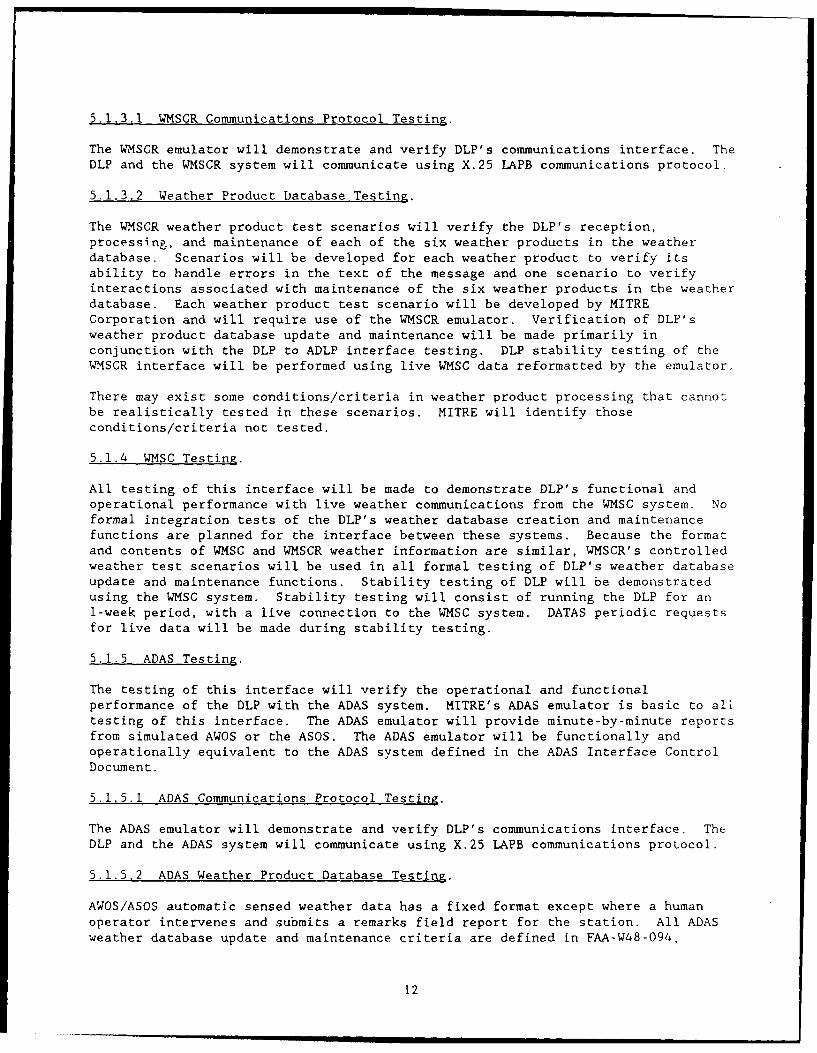
5.1.3.1 WMSCR Communications Protocol Testing.
The WMSCR emulator will demonstrate and verify DLP's communications interface. TheDLP and the WMSCR system will communicate using X.25 LAPB communications protocol.
5.1.3.2 Weather Product Database Testing.
The WMSCR weather product test scenarios will verify the DLP's reception,processing, and maintenance of each of the six weather products in the weatherdatabase. Scenarios will be developed for each weather product to verify itsability to handle errors in the text of the message and one scenario to verifyinteractions associated with maintenance of the six weather products in the weatherdatabase. Each weather product test scenario will be developed by MITRECorporation and will require use of the WMSCR emulator. Verification of DLP'sweather product database update and maintenance will be made primarily inconjunction with the DLP to ADLP interface testing. DLP stability testing of theWMSCR interface will be performed using live WMSC data reformatted by the emulator.
There may exist some conditions/criteria in weather product processing that cannotbe realistically tested in these scenarios. MITRE will identify thoseconditions/criteria not tested.
5.1.4 WMSC Testing.
All testing of this interface will be made to demonstrate DLP's functional andoperational performance with live weather communications from the WMSC system. Noformal integration tests of the DLP's weather database creation and maintenancefunctions are planned for the interface between these systems. Because the formatand contents of WMSC and WMSCR weather information are similar, WMSCR's controlledweather test scenarios will be used in all formal testing of DLP's weather databaseupdate and maintenance functions. Stability testing of DLP will be demonstratedusing the WMSC system. Stability testing will consist of running the DLP for an1-week period, with a live connection to the WMSC system. DATAS periodic requestsfor live data will be made during stability testing.
5.1.5 ADAS Testing.
The testing of this interface will verify the operational and functionalperformance of the DLP with the ADAS system. MITRE's ADAS emulator is basic to alltesting of this interface. The ADAS emulator will provide minute-by-minute reportsfrom simulated AWOS or the ASOS. The ADAS emulator will be functionally andoperationally equivalent to the ADAS system defined in the ADAS Interface ControlDocument.
5.1.5.1 ADAS Communications Protocol Testing.
The ADAS emulator will demonstrate and verify DLP's communications interface. The
DLP and the ADAS system will communicate using X.25 LAPB communications protocol.
5.1.5,2 ADAS Weather Product Database Testing.
AWOS/ASOS automatic sensed weather data has a fixed format except where a humanoperator intervenes and submits a remarks field report for the station. All ADASweather database update and maintenance criteria are defined in FAA-W48-094,
12
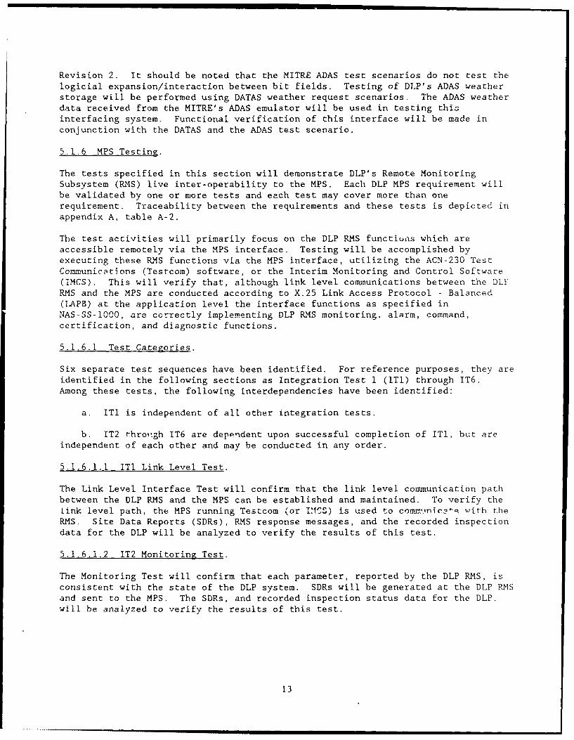
Revision 2. It should be noted that the MITRE ADAS test scenarios do not test thelogicial expansion/interaction between bit fields. Testing of DLP's ADAS weatherstorage will be performed using DATAS weather request scenarios. The ADAS weatherdata received from the MITRE's ADAS emulator will be used in testing thisinterfacing system. Functional verification of this interface will be made inconjunction with the DATAS and the ADAS test scenario.
5.1.6 MPS Testing.
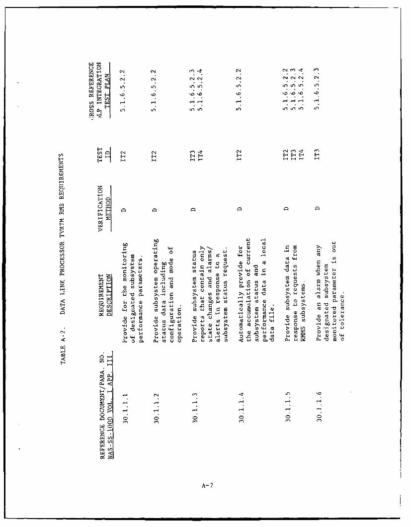
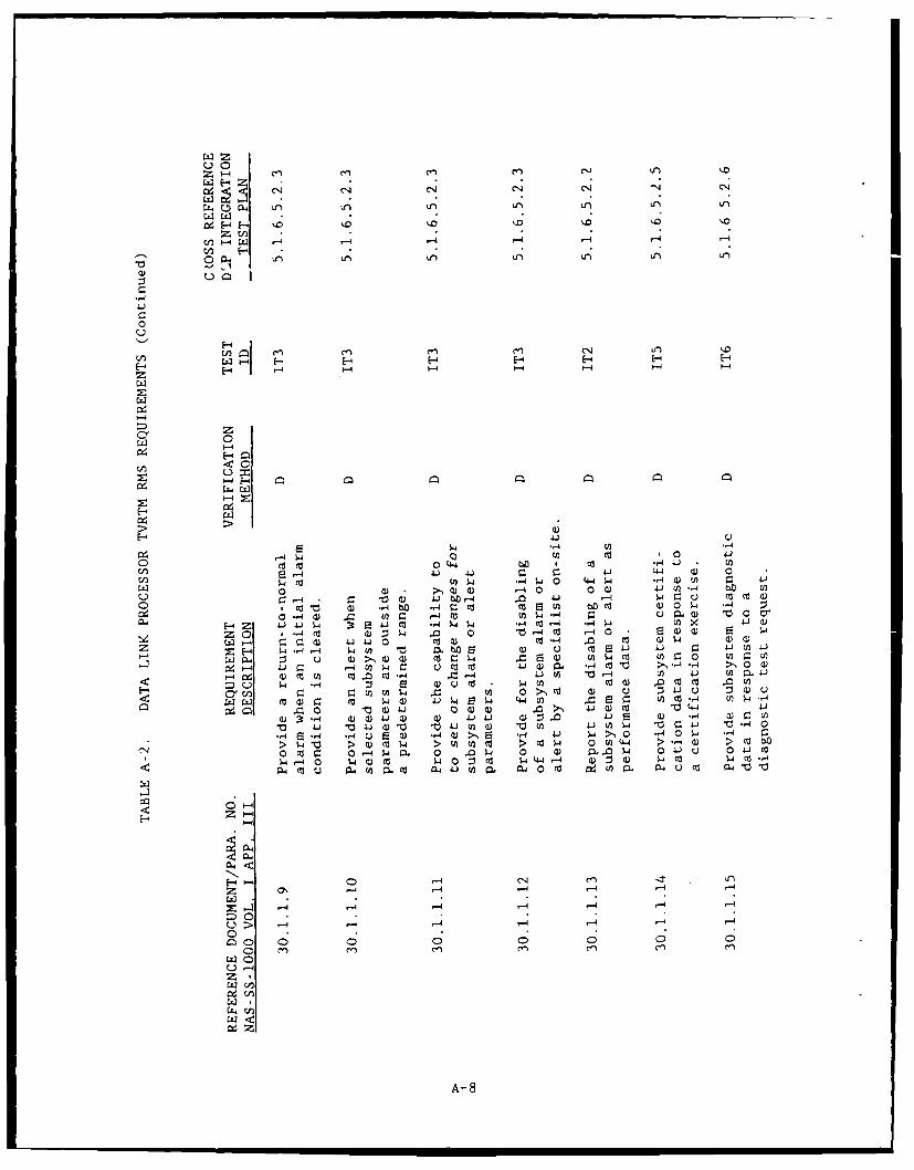
The tests specified in this section will demonstrate DLP's Remote MonitoringSubsystem (.14S) live inter-operability to the MPS. Each DLP MPS requirement willbe validated by one or more tests and each test may cover more than onerequirement. Traceability between the requirements and these tests is depicted inappendix A, table A-2.
The test activities will primarily focus on the DLP RMS functiuns which areaccessible remotely via the MPS interface. Testing will be accomplished byexecuting these RMS functions via the MPS interface, utilizing the ACN-230 TestCommunicptions (Testcom) software, or the Interim Monitoring and Control Software(IMCS). This will verify that, although link level communications between the DLYRMS and the MPS are conducted according to X.25 Link Access Protocol - Balanced(LAPB) at the application level the interface functions as specified inNAS-SS-1000, are correctly implementing DLP RMS monitoring, alarm, command,certification, and diagnostic functions.
5.1.6.1 Test Categories.
Six separate test sequences have been identified. For reference purposes, they areidentified in the following sections as Integration Test 1 (IT1) through IT6.Among these tests, the following interdependencies have been identified:
a. ITI is independent of all other integration tests.
b. IT2 through IT6 are dependent upon successful completion of ITI, but areindependent of each other and may be conducted in any order.
5.1.6.1.1 ITl Link Level Test.
The Link Level Interface Test will confirm that the link level communication pathbetween the DLP RMS and the MPS can be established and maintained. To verify thelink level path, the MPS running Testcom (or I'VCS) is used to co.inica-t with theRMS. Site Data Reports (SDRs), RMS response messages, and the recorded inspectiondata for the DLP will be analyzed to verify the results of this test.
5.1.6.1.2 IT2 Monitoring Test.
The Monitoring Test will confirm that each parameter, reported by the DLP RMS, isconsistent with the state of the DLP system. SDRs will be generated at the DLP RMSand sent to the MPS. The SDRs, and recorded inspection status data for the DLP,will be analyzed to verify the results of this test.
13
5.1.6.1.3 IT3 Alarm Test.
The Alarm Test will confirm that the DLP RMS will correctly respond to the DLP
alarm conditions via the MPS interface. The responses received by the MPS, and therecorded inspection data for the DLP, will be analyzed to verify the results ofthis test.
5.1.6.1.4 IT4 Command Test.
The Comnmand Test will confirm that the DLP RMNS will correctly respond to commandssent via the MPS irtprface. The responses received by the MPS, and the recordedinspection data for the DLP, will be analyzed to verify the results of this test.
5.1.6.1.5 IT5 Certification Test.
The Certification Test will confirm that the DLP RMS will correctly respond to the
certification commands sent via the MPS interface. The responses received by theMPS, and the recorded inspection data for the DLP, will he analyzed to verify the
results of this test.
5.1.6.1.6 IT6 Diagnostic Test.
The Diagnostic Test will confirm that the DLP RMS will correctly respond todiagnostic commands issued via the MPS interface. The r~z ~se- r-c-ived by thpMPS, and the recorded inspection data, for the DLP will be analyzed to verify theresults of this test.
5.1.7 CTS Testing.
This test will verify that the DLP can interface with and receive time from theCTS system. The CTS provides Julian day of year and time of day plus codes that
indicate accuracy of time information. The exact format of the one message sent by
the CTS shall be in accordance with the CTS (Interface Control Document (ICD).
5.2 TEST CATEGORY 02 BASIC SYSTEMS OPERATIONS.
Tests successfully completed within this category will demonstrate that the DLP canbe integrated into the NAS whenever all interfacing systems are available. Thistest incorporates all of the functional and operational characteristics of the DLP
as identified in the category associated with each interfacing system. The fullcnfiguration operational and stability performance of the DLP is included in this
test category. This test includes the following basic functional requirements ofthe DLP:
a. Weather product acquisition storage and maintenance from the WMSCR and ADASemulators plus live data from WMSC
b. Weather product retrieval
c. Weather product transmission to aircraft via Mode S sensors
d. Maintenance of the aircraft ADLP to DLP communication link via Mode S
14
e. MPS polling
f. Capacity and performance testing
Testing of these functions will be performed on the DLP using appropriate scenariosfor weather product sources and requests. These requirements will be tested usingDATAS coupled with the WMSCR and ADAS emulators.
5.2.1 Test Description.
The following test description shows the interaction between testing the DLP'sfunctions of storing and maintaining a weather database and the servicing ofrequests for weather information from this database. This interaction isnzrized in figure 5.2.1-1.
a. Weather Product Acquisition, Storage, and Maintenance
During this test, the weather source will be the simulated WMSCR and ADASemulators. The emulator test drivers will read previously prepared weather productdata (canned weather) and Lransmit it in appropriate format to the DLP. This datawill consist of valid data and will include at least one example of each type ofweather product in the full variety of formats expected from WMSCR. The DATAS,using its test scenarios derived from the above emulator weather test scenarios,will then issue requests for all these products, and compare the DLP responses withpredicted results based on the canned weather. If the weather product received bythe DATAS simulated Mode S sensor agrees with the predictions based on the cannedweather, it can be concluded that the canned weather product was properly acquiredand maintained by the DLP.
The canned weather data will include a liberal mixture of erroneous data, and asufficient spectrum of pilot reports and hazardous weather advisories to exercisethe spectrum of weather requests. Date-time groups in the weather products will beadjusted to produce gradual and predictable expiration of the products. The DATASwill issue requests for all products in the canned weather and compare responseswith predicted results.
At the end of the test, the weather reject log will be reviewed to ensure that allerroneous weather products have been properly logged, and that no valid weatherproducts ap-car. The weather reject log and the transaction file will be reviewedto estimate the storage delay time, which is also available from the simulatorlogs.
b. Weather Product Request Processing
This test case is concerned with Mode S to ADLP communications. The testing undera. Weather Product Acquisition, Storage, and Maintenance, should be sufficient todemonstrate that the DLP processing of valid requests satisfies requirements.
Invalid and improperly constructed requests still need to be tested. TheDATAS will issue a set of data link messages with all possible type codes(0-FF hexidecimal), as the first byte in an otherwise well constructed pilotdownlink without position. Most of these are invalid and should be archived butelicit no response from the DLP.
15
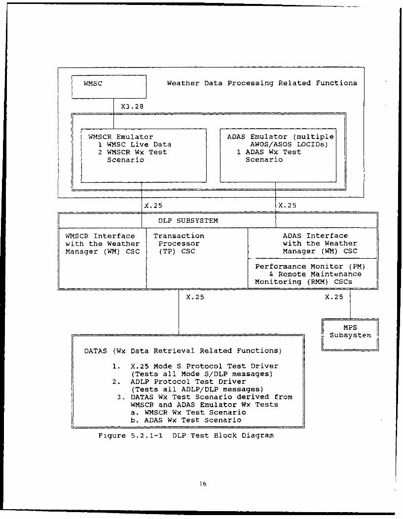
WMSC Weather Data Processing Related Functions
X3.28
WMSCR Emulator ADAS Emulator (multiple1 WMSC Live Data AWOS/ASOS LOCIDs)2 WMSCR Wx Test 1 ADAS Wx Test
Scenario Scenario
JX.25 IX.25
Ie c DLP SUBSYSTEM
WMSCR Interface Transaction ADAS Interfacewith the Weather Processor with the WeatherManager (WM) CSC (TP) CSC Manager (WM) CSC
Performance Monitor (PM)& Remote Maintenance
Monitoring (RMM) CSCs
X.25 X.25
MPS
Subsystem
DATAS (Wx Data Retrieval Related Functions)
1. X.25 Mode S Protocol Test Driver(Tests all Mode S/DLP messages)
2. ADLP Protocol Test Driver(Tests all ADLP/DLP messages)
3. DATAS Wx Test Scenario derived fromWMSCR and ADAS Emulator Wx Testsa. WMSCR Wx Test Scenariob. ADAS Wx Test Scenario
Figure 5.2.1-1 DLP Test Block Diagram
16
c. Weather Product Transmission
The previous test cases have adequately exercised the Mode S interface todemonstrate compliance with these requirements.
d. End-to-End Testing
This test involves the WMSC live weather product source (one or more live Mode Ssensors in communication with deployed Mode S ADLP equipped aircraft issuingweather product requests). This test will be an important part of IT&E because itdemonstrates the Mode S data link capability. DATAS will be used in conjunctionwith full end-to end testing to provide additional assurance that the functionalrequirements to communicate with multiple targets have been met.
e. MPS Polling and DT.P Responses
The MPS interface will be excercised via normal MPS polling of the DLP.
f. A test scenario will be executed by DATAS which excprises all DLP capacityconstraints; namely, number of active aircraft (2000) and weather product requestrates (throughput performance). Weather products storage capacity (i.e., number ofSAs) will have previously been tested during ARCON's DT&E.
5.2.2 NAS Requirements.
This test shall verify the following requirements:
NAS-SS-iO00 3.2.1.5.3.2.3, and SSS/DLP 3.1.1 through 3.1.4.2, 10.1 through10.5.9.6.
5.2.3 Criteria of Success.
The successfully co' leted and approved verification of the requirements specifiedin 5.2.2 shall be considered as the criteria for success of this test procedure.
5.2.4 Test Configuration.
Category 02 tests shall be performed on the configuration shown in figure 3.2.1-2.
5.2.5 Support Hardware.
The following support hardware is required: DATAS's Mode S to ADLP Applicationsimulation, the WMSCR and ADAS emulators, the Technical Center's MPS testbed, and aprotocol analyzer model HP-4952. End-to-end testing requires a live Mode S sensorand an airborne avionics system, including a Mode S data link capable ADLPtransponder, plus input output capabilities.
5.2.6 Support Software.
Software to support the DATAS's Mode S simulation, ACN-230 MPS Testcom, and theIMCS software is required.
17
5.2.7 Special Test Equipment.
No special test equipment has been identified to date.
5.2.8 Data Analy;sis.
This test will be precisely scripted WMSCR/ADAS emulator weather data testscenarios and the DATAS test scenarios derived from them. The deviation of systemresponses from these scripted test scenarios results in test failure. The normaloutputs generated during this test will be archived by both DATAS and the DLP, with
listings generated as required. These files are part of the documentation.
5.2.9 Documentation.
Documentation of Test Category 02 test performance and results shall be in
accordance with section 7 of this document. The normal outputs, generated duringthis test, will be captured to a magnetic medium via the archiving feature of the
DLP; listings will be generated as required. These files are a part of thedocumentation.
5.3 TEST CATEGORY 03 STARTUP, SHUTDOWN AND RESTART.
These tests shall demonstrate that Startup, Shutdown and Restart functions of theDLP can be performed with results in accordance with conditions and requirements
specified in the TVRTM.
5.3.1 Test Description.
Test personnel shall execute test scenarios associated with Startup, Shutdown and
Restart of the DLP. Each of the above functions shall produce results in strictaccordance with requirements given in the TVRTM. Any deviaticn from these
requirements shall constitute a failure of the function being tested.
5.3.2 NAS Requirements.
Tests in this category shall verify the following requirements:SSS/DLP 3.1.4.3.1, 3.1.4.3.2, and 3.1.4.3.3.
5.3.3 Criteria of Success.
The successfully completed and approved verification of the requirements, as
specified in section 5.3.2, and the TVRTM, shall be considered as the criteria forsuccess of these tests procedures.
5.3.4 Test Configuvation.
Category 03 tests shall be performed on the configuration shown in figure 3.2.1-2.
5.3.5 Support Hardware.
No support hardware has been identified to date.
18
5.3.6 Support Software.
No test support software has been identified for this testing.
5.3.7 Special Test Equipment.
No special test equipment has been identified to date.
5.3.8 Data Analysis.
This test is either pass or fail, based on the DLP's performance.
5.3.9 Documentation.
Documentation of Category 03 test performance and results shall be in accordancewith section 7 of this document. The normal outputs, generated during this test.will be captured to a magnetic medium and listings generated as required. These
files are a part of the documentation.
5.4 TEST CATEGORY 04 RECONFIGURATION.
Test personnel will use those menus associated with DLP operational parameter
chanzes to verify changes in the operational configuration.
5 Test Description.
A test scenario will be executed by test personnel which exercises everyrequirement description listed in the DLP TVRTM.
5.4.2 NAS Requirements.
These tests shall verify the following DLP requirements:
SSS/DLP 3.1.4.3.4.1, 3.1.4.3.4.2, and 3.1.4.3.5.
5.4.3 Criteria of Success.
The successfully completed and approved verification of the requirements, asspecified in section 5.4.1 and for each requirement specified in the TVRTM, shallbe considered as the criteria for success of these test procedures.
5.4.4 Test Configuration.
These tests shall be performed on the configuration shcwn in figure 3.2.1-2.
5.4.5 Support Hardware.
No special support hardware has been identified for this test.
5.4.6 Support Software.
No special support software ha hAPn idpntifip for this test.
5.4.7 Special Test Equipment.
No special test equipment has been identified to date.
19
5.4.8 Data Analysis.
All changes made in the DTP's operational configuration shall be in strictaccordancr with the operational parameters modified by the test scenario.
5.4.9 Documentation.
Documentation of the-e test performance and results shall be in accordance withsection 7 of -his document. The normal outputs, generated during this test, willbe captured to a magnetic medium and listings generated as required. These tlt:hs
are a part of the documentation.
5.5 TEST CATEGORY 05 DIAGNOSTICS.
This test category includes inventory of hardware elements and support sotcontrolling the basic hardware elements, such as memory, mass storage, tape- dprinters, Cathode Ray Tube (CRT) terminals, and communication interface de-.i,-,;Diagnostic software, supplied with the DLP hardware configuration items, ias well as the application and the system software diagnostic repertoir(:. ,Reliability and Performance Demonstration (R&PD) is also included in this t
5.5.1 Test Description.
The test procedures developed for this testing shall verify the basic intrelr,,;between FAA personnel and the new hardware that comprise the DLP svst, -m "heshall confirm the ability to perform the diagnostics and the accuracy o:supplied software and procedures. They shall demonstrate the ability of tKto meet the performance and reliability requirements. These tests are part ..into two sub-tests: (1) Functionality Demonstration, and (2) R&PD.
5.5.1.1 Functionality Demonstration.
Test personnel shall power each associated unit up and down and obervereactions. They shall execute all features and options of the diagnoti',-'..
supplied with the DLP system. They also verify the functionality of h, t,detection, isolation, and correction capabilities of the Sequoia compu.':These tests will primarily be the same as many of the hardware factory a-,i crtest run by CONTEL. They shall exercise such things as the mount, JJ.rr(' ;,, -read, write, and protection capabilities of the magnetic tape hardware, irld
supporting software.
5.5.1.2 Reliability and Performance Demonstration.
The R&PD will ccnsist of a continuously running DLP program operarint wi!'hemulators and simulators providing weather data and Mode S/ADLP intertac:, 'normal load conditions. The DLP will be run continuously for I week to .i':. ,.performance statistics and the mean time to failure of the system. DAT \"iroutinely make various requests for weather information d,,ring this test
. ... .......... . .. - -- == = .rms m un m l l u0
5.5.2 NAS Requirements.
These tests shall verify the following requirements:
SSS/DLP 3.1.1, 3.1.4.2.3, 3.1.4.5.9.1, 3.1.4.5.9.3, 3.1.4.5.9.4, 3.1.4.5.9.5, and10.5.9.7ff.
HWS/DLP 3.1.lff, 3.1.2ff, 3.1.3ff, 3.2.lff, 3.2.3ff, and 3.2.4.3.
5.5.3 Criteria of Success.
The successfully completed and approved verification of the requirements, asspecified in both section 5.5.2 and with the identified methods for eachrequirement in the TVRTM, shall be considered as the criteria for success of thesetest procedures.
5,5.4 Test Configuration.
Category 05 tests shall be performed on the configuration shown in figure 3.2.1-2.
5.5.5 Support Hardware.
All DLP hardware elements and simulators and emulators are required for thesetests.
5.5.6 Support Software.
The defined R&PD program and data generators supporting simulation scenarios arerequired for the R&PD test.
5.5.7 Special Test Equipment.
No special test equipment has been identified to date.
5.5.8 Data Analysis.
a. With regard to the functional requirements being tested, this test will beprecisely scripted in the test procedures so that deviations of system responsesfrom the script result in test failure,
b. Performance and reliability requirements will require statistical analysis toevaluate the results, i.e., if no failures are observed, a lower limit on the meantime to failure may be estimated statistically.
5.5.9 Documentation.
Documentation of these tests performance and results shall be in accordance withsection 7 of this document. The outputs generated during this test will becaptured to a magnetic medium and listings generated as required. These files arepart of the documentation.
21

5.6 TEST CATEGORY 06 SECURITY.
The need to implement security into the DLP software is a must to restrict unwanted
access to the databases. Two levels shall be included with the first being a meansto automatically generate a log-on record and enable the user general purposeutilitization. The second level shall be more restritive and be available forthose who have a need to know.
5.6.1 Test Description.
Testing shall be conducted that will demonstrate that with correct access personnelwill be permitted to propertly operate the functional aspects oc the DLP system.
Equal testing will demonstrate that improper access will not be permitted.
5.6.2 NAS Requirements.
There are no specific requirements stated for this in the DLP specifications, butis required as per FAA Order 1600.54b.
6. DLP TESTING ORGANIZATIONAL ROLES AND RESPONSIBILITIES.
The principal groups involved in the DLP Integration Test activities are the test
management group and the test support group.
6.1 DLP TEST MANAGEMENT GROUP.
6.1.1 Composition of the DLP Test Management Group.
The DLP test management group will be composed of representatives from FAA agenciesand support contractors. Specifically, it will be composed of one member from
each of the following organizations: ACN-220 (who will chair the group), ASM-160,AAC-942D, ACD-320, ACN-230, MITRE, MiTech, STI, and System Engineering and
Integration (SEI)- Technical Center Operations (TCO).
6.1.2 Role of the DLP Test Management Group.
The role of this group is to direct all test efforts relative to the DLP Test andEvaluation (ThE) activities. The DLP test management group will coordinate and
assign particular tasks to each crganization represented in the DLP test support
group.
6.1.3 Responsibilities of the DLP Test Management Group.
Specific responsibilities of the DLP test r3nagement group are the following:
a. Establish and promulgate policies related to the DLP T&E activities.
b. Concur with all test plans and procedures related to the DLP T&E
activities.
22
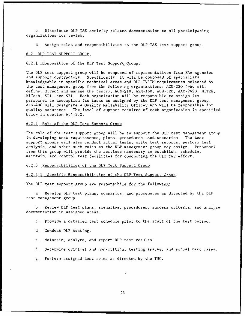
c. Distribute DLP T&E activity related documentation to all participating
organizations for review.
d. Assign roles and responsibilities to the DLP T&E test support group.
6.2 DLP TEST SUPPORT GROUP.
6.2.1 Composition of the DLP Test Support Group.
The DLP test support group will be composed of representatives from FAA agenciesand support contractors. Specifically, it will be composed of specialistsknowledgeable in specific technical areas and DLP TVRTM requirements selected bythe test management group from the following organizations: ACN-220 (who willdefine, direct and manage the tests), ACN-210, ASM-160, ACD-320, AAC-942D, MITRE,MiTech, STI, and SEI. Each organization will be responsible to assign itspersoiunel to accomplish its tasks as assigned by the DLP test management group.ALG-400 will designate a Quality Reliability Officer who will be responsible forquality assurance. The level of support required of each organization is specifiedbelow in section 6.4.2.2.
6.2.2 Role of the DLP Test Support Group.
The role of the test support group will be to support the DLP test management groupin developing test requirements, plans, procedures, and scenarios. The testsupport groups will also conduct actual tests, write test reports, perform testanalysis, and other such roles as the DLP management group may assign. Personnelfrom this group will provide the services necessary to establish, schedule,maintain, and control test facilities for conducting the DLP T&E effort.
6.2.3 Responsibilities of the DLP Test Support Group.
6.2.3.1 Specific Responsibilities of the DLP Test Support Group.
The DLP test support group are responsibile for the following:
a. Develop DLP test plans, scenarios, and procedures as directed by the DLPtest management group.
b. Review DLP test plans, scenarios, procedures, success criteria, and analyzedocumentation in assigned areas.
c. Provide a detailed test schedule prior to the start of the test period.
d. Conduct DLP testing.
e. Maintain, analyze, and report DLP test results.
f. Determine critical and non-critical testing issues, and actual test cases.
g. Perform assigned test roles as directed by the TMG.
23

6.2.3.2 Primary Responsibilities and Support Functions.
The following defines tasking responsibilities:
a. ACN-220 will prepare and review the DLP's Operational Test andEvaluation/Integration Test Plan and all associated procedures. ACN-220 willalso review compliance of test programs with FAA Orders 1810.4a and 1600.54b, andwill monitor Installation and Checkout (I&CO) of the first system. They willprovide support to the Program Manager for all T&E phases and will be responsiblefor and conduct testing.
b. ACN-220 will operate and maintain the test facility laboratories and thesystem test bed. They will also provide scheduling service to all shared resourcelaboratory users.
c. ACD-320 will provide DATAS for extensive functional testing of the Mode Sand ADLP systems and will provide the ADLP avionics package for end-to-end testingof the Mode S data link.
d. ASM-160 will be responsible for the development and preparation of theShakedown Test Plan and Test Procedures and the DLP Maintenance Handbook. It willbe responsible for and will conduct shakedown testing at the FAA Technical Center.
e. AAC-942D will be responsible for training.
f. ACN-230 will provide an MPS system for testing the interface between DLPand the MPS.
g. SEI will coordinate and assist in the development of all DLP test plans,
procedures, and execution activities.
6.3 DLP INTEGRATION TEST MANAGEMENT.
6.3.1 Definition of Roles.
Definitions of the roles involved in the DLP T&E integration and verificationeffort follows. Every defined role need not necessarily be staffed for every test.
6.3.1.1 DLP Test Director (ACN-220).
The test director is responsible for the overall management of the DLP OperationalTest and Evaluation effort, for conducting pretest and post-test briefings, and forthe collection of all applicable data for subsequent analysis. The test directorprovides management guidance through the test coordinator and other members of thetest team.
6.3.1.2 DLP Test Coordinator (ACN-220).
The test coordinator is responsible for the overall DLP test coordination to ensurethat individual missions are properly structured and mission objectives areaccomplished. The test coordinator will select the test manager for each testbased upon suitability, expertise, and availability. The test coordinator willwork with the test director on unresolved problems, recommend remedial action, andprovide general support to the test director.
24
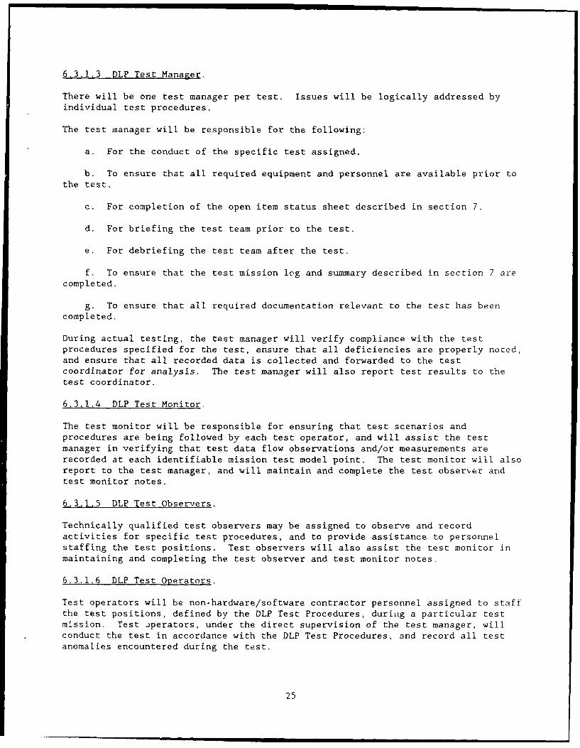
6.3.1.3 DLP Test Manager.
There will be one test manager per test. Issues will be logically addressed byindividual test procedures.
The test manager will be responsible for the following:
a. For the conduct of the specific test assigned.
b. To ensure that all required equipment and personnel are available prior tothe test.
c. For completion of the open item status sheet described in section 7.
d. For briefing the test team prior to the test.
e. For debriefing the test team after the test.
f. To ensure that the test mission log and summary described in section 7 arecompleted.
g. To ensure that all required documentation relevant to the test has beencompleted.
During actual testing, the test manager will verify compliance with the testprocedures specified for the test, ensure that all deficiencies are properly noted,and ensure that all recorded data is collected and forwarded to the testcoordinator for analysis. The test manager will also report test results to thetest coordinator.
6.3.1.4 DLP Test Monitor.
The test monitor will be responsible for ensuring that test scenarios andprocedures are being followed by each test operator, and will assist the testmanager in verifying that test data flow observations and/or measurements arerecorded at each identifiable mission test model point. The test monitor will alsoreport to the test manager, and will maintain and complete the test observer andtest monitor notes.
6.3.1.5 DLP Test Observers.
Technically qualified test observers may be assigned to observe and recordactivities for specific test procedures, and to provide assistance to personnelstaffing the test positions. Test observers will also assist the test monitor inmaintaining and completing the test observer and test monitor notes.
6.3.1.6 DLP Test Operators.
Test operators will be non-hardware/software contractor personnel assigned to staffthe test positions, defined by the DLP Test Procedures, during a particular testmission. Test operators, under the direct supervision of the test manager, willconduct the test in accordance with the DLP Test Procedures, and record all testanomalies encountered during the test.
25
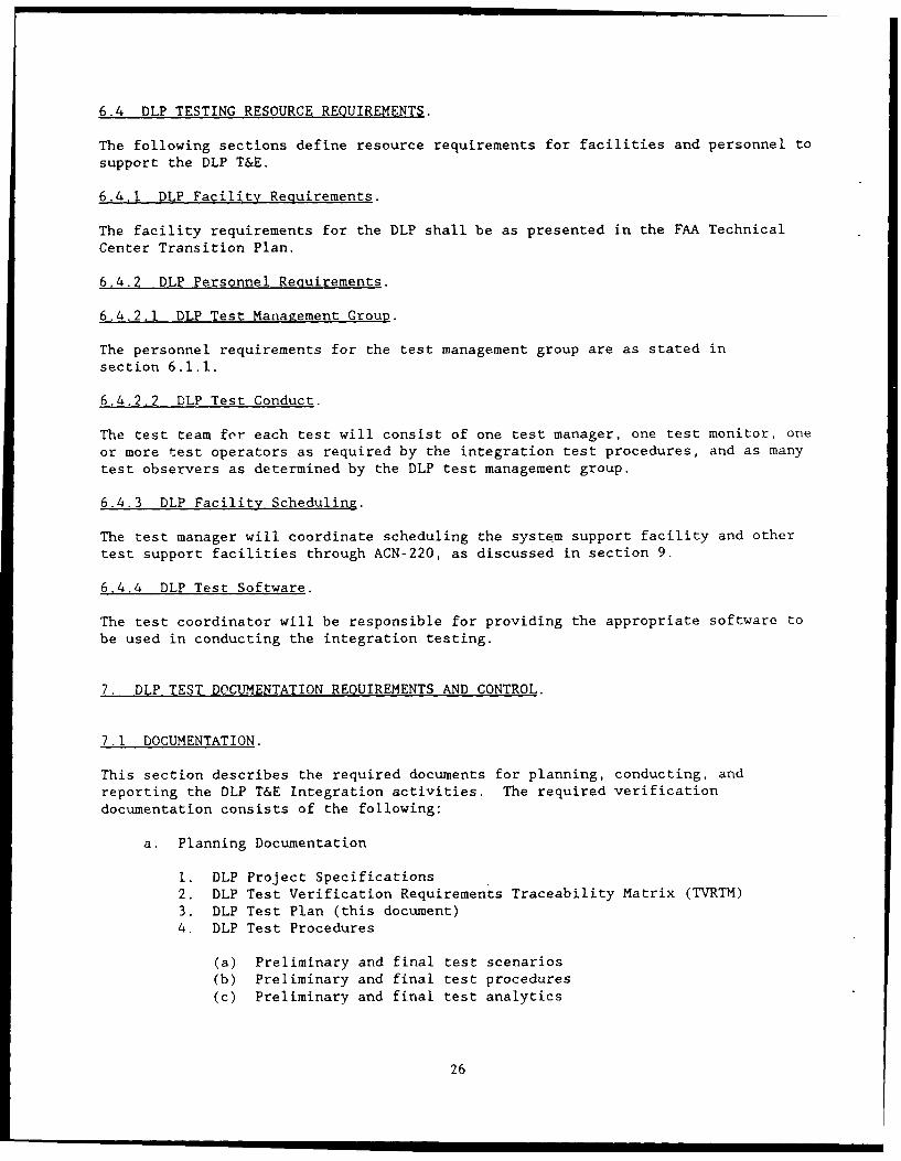
6.4 DLP TESTING RESOURCE REQUIREMENTS.
The following sections define resource requirements for facilities and personnel to
support the DLP T&E.
6.4.1 DLP Facility Requirements.
The facility requirements for the DLP shall be as presented in the FAA Technical
Center Transition Plan.
6.4.2 DLP Personnel Requirements.
6.4.2.1 DLP Test Management Group.
The personnel requirements for the test management group are as stated in
section 6.1.1.
6.4.2.2 DLP Test Conduct.
The test team for each test will consist of one test manager, one test monitor, one
or more test operators as required by the integration test procedures, and as many
test observers as determined by the DLP test management group.
6.4.3 DLP Facility Scheduling.
The test manager will coordinate scheduling the system support facility and other
test support facilities through ACN-220, as discussed in section 9.
6.4.4 DLP Test Software.
The test coordinator will be responsible for providing the appropriate software to
be used in conducting the integration testing.
7. DLP TEST DOCUMENTATION REQUIREMENTS AND CONTROL.
7.1 DOCUMENTATION.
This section describes the required documents for planning, conducting, andreporting the DLP T&E Integration activities. The required verification
documentation consists of the following:
a. Planning Documentation
i. DLP Project Specifications2. DLP Test Verification Requirements Traceability Matrix (TVRTM)
3. DLP Test Plan (this document)
4. DLP Test Procedures
(a) Preliminary and final test scenarios
(b) Preliminary and final test procedures(c) Preliminary and final test analytics
26
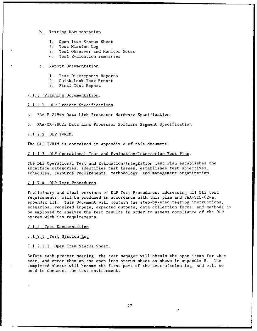
b. Testing Documentation
1. Open Item Status Sheet2. Test Mission Log
3. Test Observer and Monitor Notes4. Test Evaluation Summaries
c. Report Documentation
i. Test Discrepancy Reports2. Quick-Look Test Report
3. Final Test Report
7.1.1 Planning Documentation.
7.1.1.1 DLP Project Specifications.
a. FAA-E-2794a Data Link Processor Hardware Specification
b. FAA-OR-2802a Data Link Processor Software Segment Specification
7.1.1.2 DLP TVRTM.
The DLP TVRTM is contained in appendix A of this document.
7.1.1.3 DLP Operational Test and Evaluation/Integration Test Plan.
The DLP Operational Test and Evaluation/Integration Test Plan establishes theinterface categories, identifies test issues, establishes test objectives,schedules, resource requirements, methodology, and management organization.
7.1.1.4 DLP Test Procedures.
Preliminary and final versions of DLP Test Procedures, addressing all DLP testrequirements, will be produced in accordance with this plan and FAA-STD-024a,
appendix III. This document will contain the step-by-step testing instructions,scenarios, required inputs, expected outputs, data collection forms, and methods tobe employed to analyze the test results in order to assess compliance of the DLP
system with its requirements.
7.1.2 Test Documentation.
7.1.2.1 Test Mission Log.
7.1.2.1.1 Open Item Status Sheet.
Before each pretest meeting, the test manager will obtain the open items for that
test, and enter them on the open item status sheet as shown in appendix B. Thecompleted sheets will become the first part of the test mission log, and will be
used to document the test environment.
27
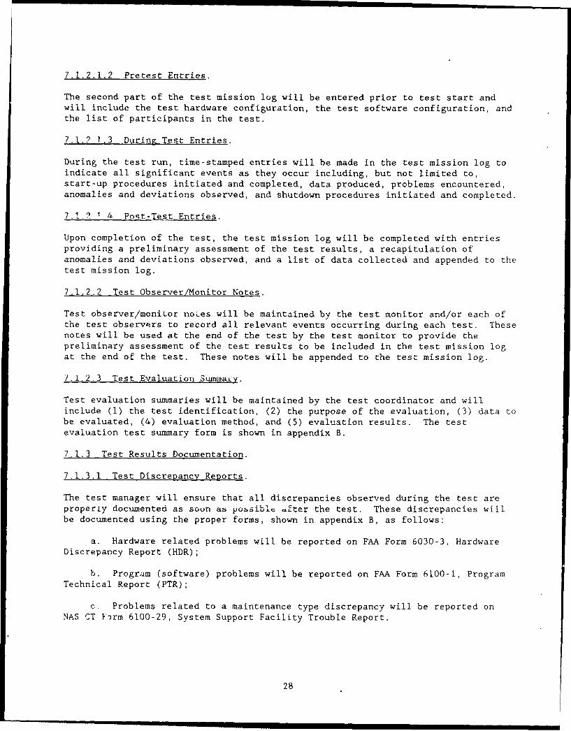
7.1.2.1.2 Pretest Entries.
The second part of the test mission log will be entered prior to test start andwill include the test hardware configuration, the test software configuration, andthe list of participants in the test.
7.1.? 1.3 During Test Entries.
During the test run, time-stamped entries will be made in the test mission log toindicate all significant events as they occur including, but not limited to,start-up procedures initiated and completed, data produced, problems encountered,anomalies and deviations observed, and shutdown procedures initiated and completed.
7.11. 1I. Poqt-Test Entries.
Upon completion of the test, the test mission log will be completed with entriesproviding a preliminary assessment of the test results, a recapitulation ofanomalies and deviations observed, and a list of data collected and appended to thetest mission log.
7.1.2.2 Test Observer/Monitor Notes.
Test observer/monitor noLes will be maintained by the test monitor and/or each ofthe test observers to record all relevant events occurring during each test. Thesenotes will be used at the end of the test by the test monitor to provide thepreliminary assessment of the test results to be included in the test mission logat the end of the test. These notes will be appended to the test mission log.
7.1.2.3 Test Evaluation Summaiy.
Test evaluation summaries will be maintained by the test coordinator and willinclude (1) the test identification, (2) the purpose of the evaluation, (3) data tobe evaluated, (4) evaluation method, and (5) evaluation results. The testevaluation test summary form is shown in appendix B.
7.1.3 Test Results Documentation.
7.1.3.1 Test Discrepancy Reports.
The test manager will ensure that all discrepancies observed during the test areproperly documented as soon ab possible after the test. These discrepancies willbe documented using the proper forms, shown in appendix B, as follows:
a. Hardware related problems will be reported on FAA Form 6030-3, Hardware
Discrepancy Report (HDR);
b. Program (software) problems will be reported on FAA Form 6100-1, Program
Technical Report (PTR);
c. Problems related to a maintenance type discrepancy will be reported onNAS CT hrm 6100-29, System Support Facility Trouble Report.
28
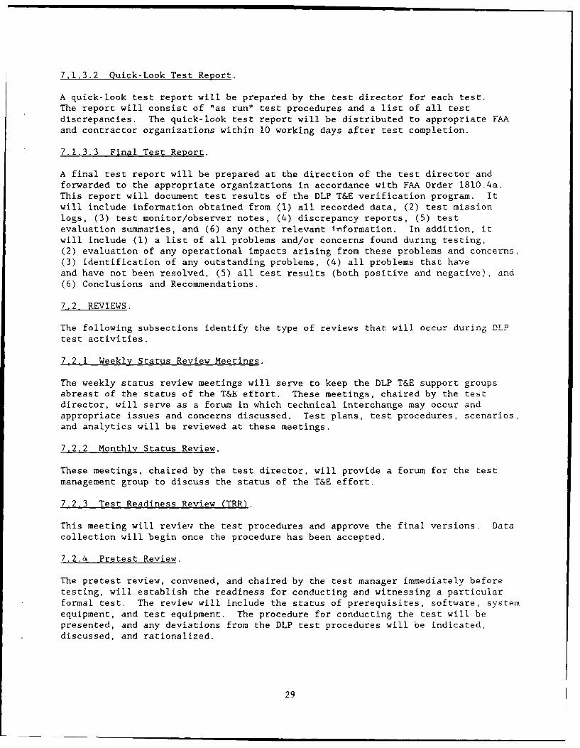
7.1.3.2 Quick-Look Test Report.
A quick-look test report will be prepared by the test director for each test.The report will consist of "as run" test procedures and a list of all testdiscrepancies. The quick-look test report will be distributed to appropriate FAAand contractor organizations within 10 working days after test completion.
7.1.3.3 Final Test Report.
A final test report will be prepared at the direction of the test director andforwarded to the appropriate organizations in accordance with FAA Order 1810.4a.This report will document test results of the DLP T&E verification program. Itwill include information obtained from (1) all recorded data, (2) test missionlogs, (3) test monitor/observer notes, (4) discrepancy reports, (5) testevaluation summaries, and (6) any other relevant information. In addition, itwill include (1) a list of all problems and/or concerns found during testing,
(2) evaluation of any operational impacts arising from these problems and concerns,(3) identification of any outstanding problems, (4) all problems that haveand have not been resolved, (5) all test results (both positive and negative), and(6) Conclusions and Recommendations.
7.2 REVIEWS.
The following subsections identify the type of reviews that will occur during DLPtest activities.
7.2,1 Weekly Status Review Meetings.
The weekly status review meetings will serve to keep the DLP T&E support groupsabreast of the status of the T&E effort. These meetings, chaired by the testdirector, will serve as a forum in which technical interchange may occur andappropriate issues and concerns discussed. Test plans, test procedures, scenarios,and analytics will be reviewed at these meetings.
7.2.2 Monthly Status Review.
These meetings, chaired by the test director, will provide a forum for the test
management group to discuss the status of the T&E effort.
7.2.3 Test Readiness Review (TRR).
This meeting will revieTj the test procedures and approve the final versions. Datacollection will begin once the procedure has been accepted.
7.2.4 Pretest Review.
The pretest review, convened, and chaired by the test manager immediately beforetesting, will establish the readiness for conducting and witnessing a particularformal test. The review will include the status of prerequisites, software, systemequipment, and test equipment. The procedure for conducting the test will bepresented, and any deviations from the DLP test procedures will be indicated,discussed, and rationalized.
29
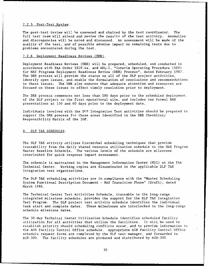
7.2.5 Post-Test Review.
The post-test review will be convened and chaired by the test coordinator. Thefull test team will attend and review the results of the test activity. Anomaliesand discrepancies will be noted and discussed. An assessment will be made of thequality of the test, and of possible adverse impact on remaining tests due toproblems encountered during the test.
7.2.6 Deployment Readiness Reviews (DRR).
Deployment Readiness Reviews (DRR) will be prepared, scheduled, and conducted inaccordance with FAA Order 1810.4a, and ADL-I, "Interim Operating Procedure (lOP)for NAS Programs Deployment Readiness Review (DRR) Process", dated February 1987.The DRR process will provide the status on all of the DLP project activities,identify open issues, and enable the formulation of conclusions and recommrendations
to these issues. The DRR also ensures that adequate attention and resources are
focused on these issues to effect timely resolution prior to deployment.
The DRR process commences not less than 180 days prior to the scheduled deploymentof the DLP project to the first operational site, and includes two formal DRR
presentations at 150 and 60 days prior to the deployment date.
Individuals involved with the DIP Integration Test activities should be prepared tosupport the DRR process for those areas identified in the DRR Checklist/
Responsibility Matrix of the lOP.
8. DLP T&E SCHEDULES.
The DLP T&E activity utilizes hierarchal scheduling techniques that providetraceability from the daily shared resource utilization schedule to the NAS ProgramMaster Baseline Schedule. The various levels of the schedule are milestoneinterlocked for quick response impact assessment.
The scheaule is maintained in the Management Information Center (MIC) at the FAA
Technical Center. Working copies are disseminated to the applicable DLP T&EIntegration test organizations.
The DLP T&E scheduling activities are in compliance with the "Master SchedulingSystem Functional Description Document - NAS Transition Phase" (Draft), datedMarch 1986.
The Technical Center Test Activities Schedule, traceable to the long-rangeintegrated milestone schedule, provides the support for the DLP T&E IntegrationTest Program. The DLP project test activity schedule identifies the individualtask start and complete dates. These milestones are interlocked to the long-range
schedule milestone dates.
The 30-day Technical Center Utilization Schedule identifies scheduled facilityutilization for all activities that utilize the facilities. It will be used toestablish priority should scheduling conflicts occur, and to provide information tothe ACN Facility Control Office schedule. Appropriate ACN Facility Control Officeschedule request forms are completed by the DLP test manager, and forwarded toACN-300. The facility schedules are produced and distributed by AGN-300.
30
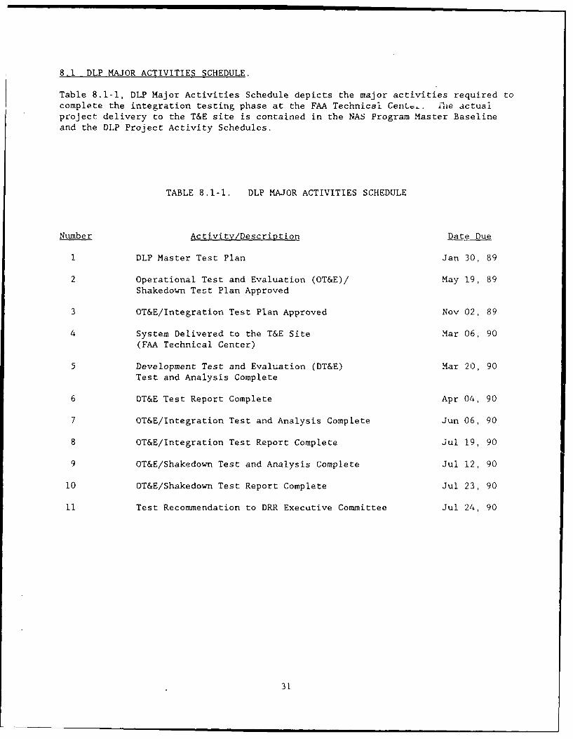
8.1 DLP MAJOR ACTIVITIES SCHEDULE.
Table 8.1-1, DLP Major Activities Schedule depicts the major activities required tocomplete the integration testing phase at the FAA Technical Cent.. Lhe actualproject delivery to the T&E site is contained in the NAS Program Master Baseline
and the DLP Project Activity Schedules.
TABLE 8.1-1. DLP MAJOR ACTIVITIES SCHEDULE
Number Activity/Description Date Due
I DLP Master Test Plan Jan 30, 89
2 Operational Test and Evaluation (OT&E)/ May 19, 89
Shakedown Test Plan Approved
3 OT&E/Integration Test Plan Approved Nov 02, 89
4 System Delivered to the T&E Site Mar 06, 90
(FAA Technical Center)
5 Development Test and Evaluation (DT&E) Mar 20, 90
Test and Analysis Complete
6 DT&E Test Report Complete Apr 04, 90
7 OT&E/Integration Test and Analysis Complete Jun 06, 90
8 OT&E/Integration Test Report Complete Jul 19, 90
9 OT&E/Shakedown Test and Analysis Complete Jul 12, 90
10 OT&E/Shakedown Test Report Complete Jul 23, 90
11 Test Recommendation to DRR Executive Committee Jul 24, 90
31

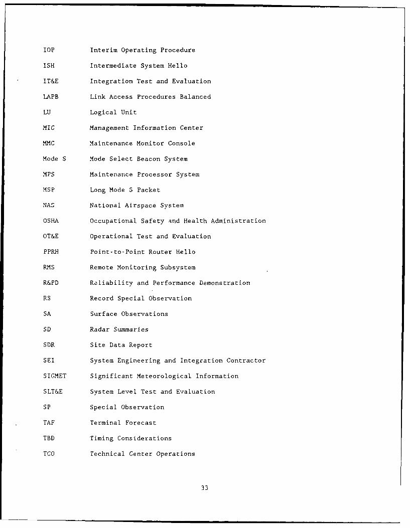
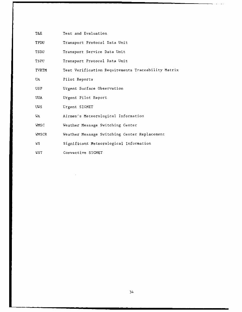
9. ABBREVIATIONS AND ACRONYMS.
ADAS AWOS Data Acquisition System
ADLP Airburne Data Link ProcesZor
AIRMET Airmen's Meteorological Infornation
ANST American National Standards Institute
ASOS Automatic Weather Surface Observing System
ATC air traffic control
ATCRBS Air Traffic Control Radar Beacon System
AWOS Automated Weather Observation System
CCITT Consultative Committee for International Telegraph and Telephone
COR Correction
CRT Cathode Ray Tube
CTS Coded Tim Source
DATAS Data Link and Transponder Analysis System
DLP Data Link ProcessoL
DP Data Points
DRR Deployment Readiness Review
DT&E Development Test and Evaluation
ELM Extended Length Message
FAA Federal Aviation Administration
FD Wind and Temperature Aloft Forecasts
FT Terminal Forecasts
ICAO International Civil Aviation Organization
ICD Interface Control Document
I&CO Installation and Checkout
ID Identification
IMCS Interim Monitoring and Control Software
32
lOP Interim Operating Procedure
ISH Intermediate System Hello
IT&E Integration Test and Evaluation
LAPB Link Access Procedures Balanced
LU Logical Unit
MIC Management Information Center
MMC Maintenance Monitor Console
Mode S Mode Select Beacon System
MPS Maintenance Processor System
MSP Long Mode S Packet
NAS National Airspace System
OSHA Occupational Safety and Health Administration
OT&E Operational Test and Evaluation
PPRH Point-to-Point Router Hello
RMS Remote Monitoring Subsystem
R&PD Reliability and Performance Demonstration
RS Record Special Observation
SA Surface Observations
SD Radar Summaries
SDR Site Data Report
SEI System Engineering and Integration Contractor
SIGMET Significant Meteorological Information
SLT&E System Level Test and Evaluation
SP Special Observation
TAF Terminal Forecast
TBD Timing Considerations
TCO Technical Center Operations
33
T&E Test and Evaluation
TPDU Transport Protocol Data Unit
TSDU Transport Service Data Unit
TSPU Transport Protocol Data Unit
TVRTM Test Verification Requirements Traceability Matrix
UA Pilot Reports
USP Urgent Surface Observation
UUA Urgent Pilot Report
U 4S Urgent SIGMET
WA Airmen's Meteorological Information
WMSC Weather Message Switching Center
WMSCR Weather Message Switching Center Replacement
WS Significant Meteorological Information
WST Convective SIGMET
34

APPENDIX A
TVRTM
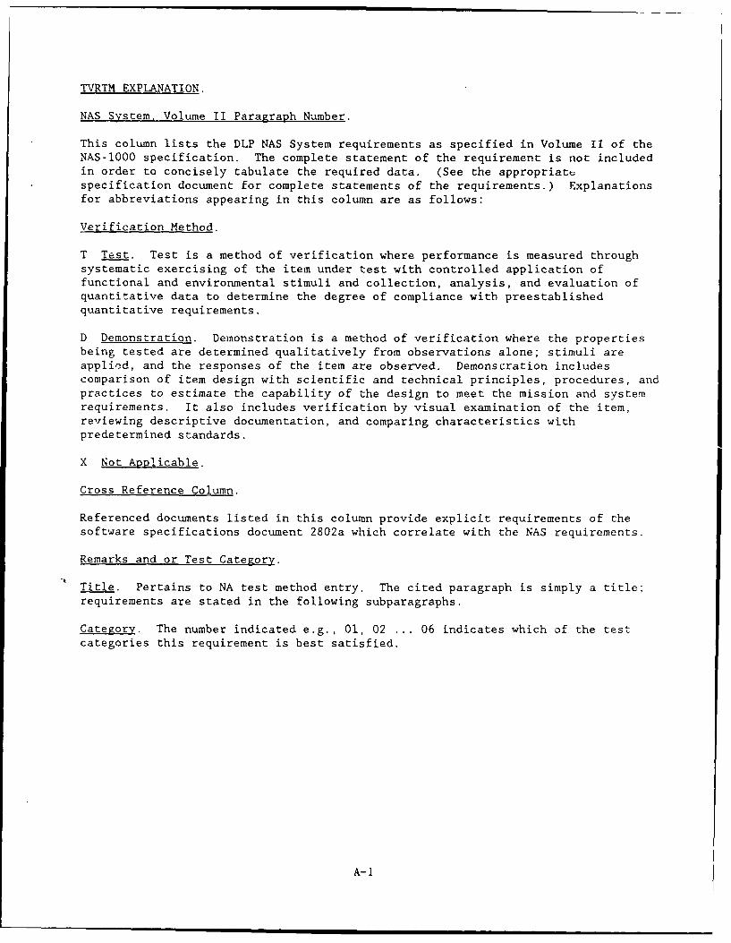
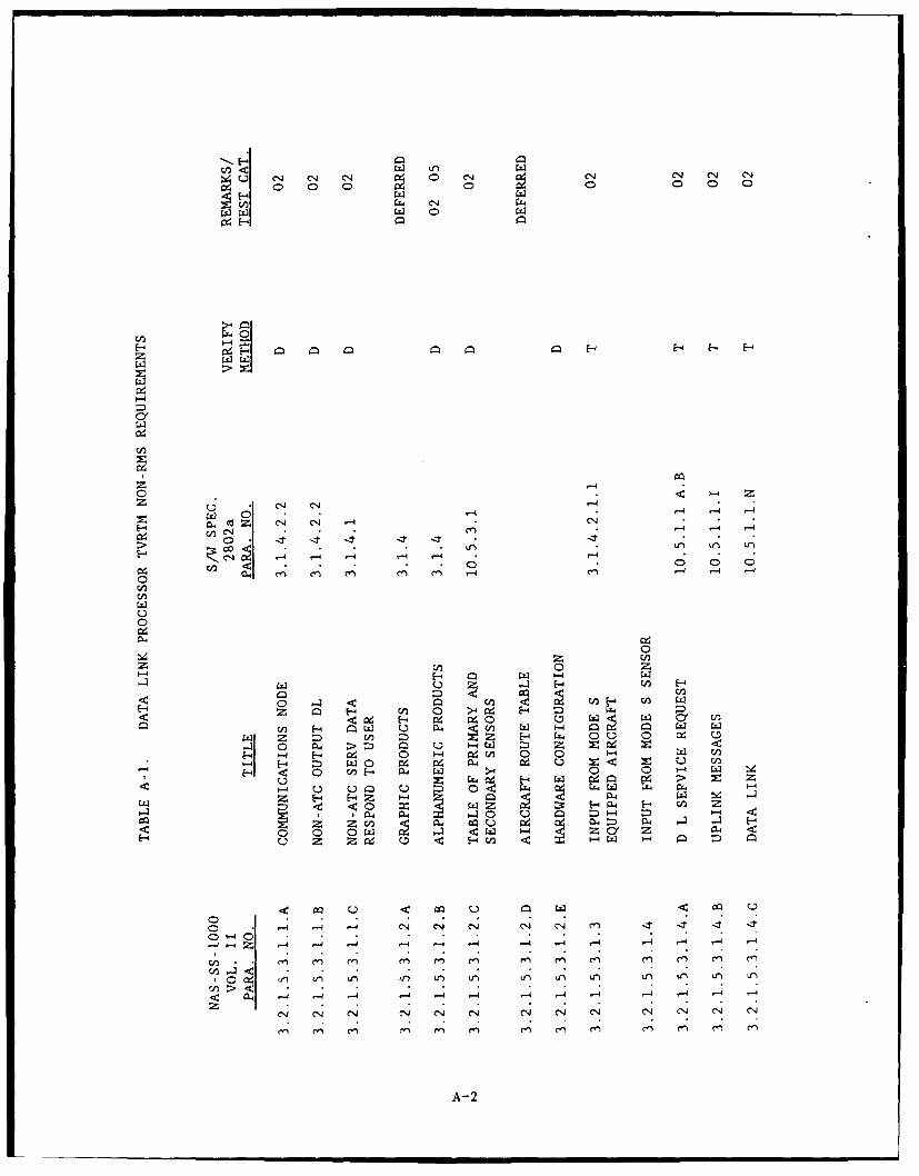
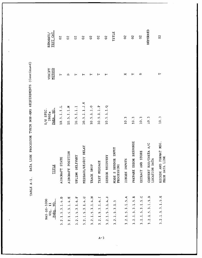
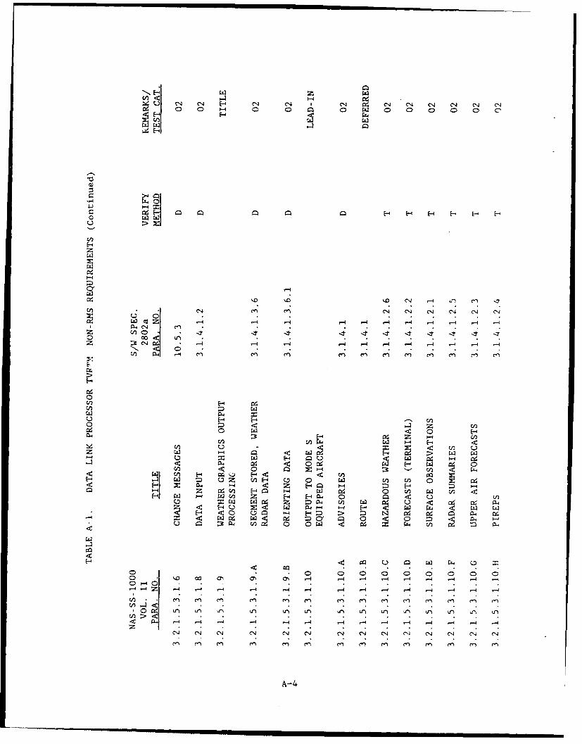
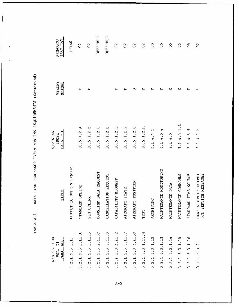
TVRTM EXPLANATION.
NAS System, Volume II Paragraph Number.
This column lists the DLP NAS System requirements as specified in Volume II of theNAS-o000 specification. The complete statement of the requirement is not includedin order to concisely tabulate the required data. (See the appropriatespecification document for complete statements of the requirements.) Explanationsfor abbreviations appearing in this column are as follows:
Verification Method.
T Test. Test is a method of verification where performance is measured throughsystematic exercising of the item under test with controlled application offunctional and environmental stimuli and collection, analysis, and evaluation ofquantitative data to determine the degree of compliance with preestablishedquantitative requirements.
D Demonstration. Demonstration is a method of verification where the propertiesbeing tested are determined qualitatively from observations alone; stimuli areapplied, and the responses of the item are observed. Demonscration includescomparison of item design with scientific and technical principles, procedures, andpractices to estimate the capability of the design to meet the mission and systemrequirements. It also includes verification by visual examination of the item,reviewing descriptive documentation, and comparing characteristics withpredetermined standards.
X Not Applicable.
Cross Reference Column.
Referenced documents listed in this column provide explicit requirements of thesoftware specifications document 2802a which correlate with the NAS requirements.
Remarks and or Test Category.
Title. Pertains to NA test method entry. The cited paragraph is simply a title;requirements are stated in the following subparagraphs.
Category. The number indicated e.g., 01, 02 ... 06 indicates which of the testcategories this requirement is best satisfied.
A-i
0 C00 0 0 C0 0
w 0M
E-4
-- 4
0 C4 C1 -4 -4 -
C2 - -4>/
4 00 0t' 0n 0r
E - Cl i - 44 1 .4
00
0 ~
0-4 0 0
H -) H4 04 &-44C~ 0 0 x1- H: 0 u0 Ce t)n4
C Z H: :H D Z E- 0 U0 A4
.4 E-4 40 W W PW HWI
C: 44. HH 0 0 - z- Im 0.::3 E-4 04 E-: HC4:0
CL4 44 1 _I 0 0D ts4 4: -
0 * w m- 04 :D MN N4 -1 E-4~
00 * * w * 4 z za
1.4 1-4 ,-4 C14 4N -4C1
14 - -4 -- 4 4 -4 - 4 -4 - 4 - 4 -
Zn C1 rn en*) e n e
A- 2
uN C1 C4 C1 4 0NJ CN C14 C4 C1J (N N4
000 0 04 0 C
4 =4
zH 1- -4 E- E- F HX H
z
U ,.4 -4 -4 -4 -4 . 4
PL-04 - 4 r -4 -4 4 -I*.-4
En C0. .
Z 1- -e o C 0 0 0 0 0 0 0 00
00
w (L -
E~~ 0 - lc Di
04 04 4 C1 H 9w W 0
A H E-4 cm ~ W En~ " C/' /' 4
E- u. CA 0 n H 0 -HZl 0c '-4 W C 04 H
V)~. E- An W u 0 134 C;4 0 ud. CJ >Z 0 0
H E- PL4 Cd.' 04 H4 ;d' x0
4 L 04 Z -4-4 -4 C, -4 -
-4-' 4 -- 4 -4 -4 '- - 4 1 -4 ,-4 .-4 ,4 -
C1 C1 C4 C14~ C4 ,.- C4 C1 -4 -N 14 C14 C
A- 3
U C14 C1 - C4 C1 1 4 C4 C14 04J C14 C'J
-- 4
o4 E-- 0- -E
E-z
*C14 c'. c'J C14 c'J C4 C14 c'JU
E-44
z z0 -
0j06C'CA
43 u z.A U
z - A -: - - -
Z~ ;: 0 64 En4
w 04 c-q> U '
0 :D 9 -
-t 91 En 0 Cd M4..
o* *0 0 0 0 C0 0C00o '0 00 0. a, O 4 -4 r-4 '-4 '-4 -4 -4 -4 '-4
En . n C.n ( C'l CC) rn e'n Cn m C m e
-4 -4J CJ e. N -4 -'4 C4 4' -44 -(4
C."' C") C) c.") C) C14 C14 C14 C4) C14 (14
A-4
.4 C14 04. C'.4 0 C14 C'J C') Lfl U1 L1) LI) C,:x -4 0 0 0 0 0 0
9~ p E-H- - H Im H H- H- X E-4 E-4
0Wu
-4
C4 -14 C14 C4 .C4
Co CN~ . . . -4 -4 -4 - -4*Z -1 < 0 0 0 0 0 0 0 0
z A-44 ~-4 ~-4 -4 .-4 4 4-4 -4 C'i C'i "I cli cn t-1
cie00
0V)r H z
0 [- -4 UECx H1:z E-4 0J W 0
CzY Hn 0 -
1:1 W z 4Y -4P' -4 0 -4 < r
E -4 0 4 0 0 w
EA 0 z H - F4 u z 0"
z 0 z H E- 0
C4 W. r -4 '-4 4-4z
H C) w E- w :.
C0 -4 14 -4 ~ - ~ -4 4 - C14 C')11t4Co 1 -4 -4 - 4 -4 -1 - -4 1-4 r-4 .-4 -4 4-4 '-A -
,L 1. 4 - - 4 -4 -4 -4 -4 -4 r-4 -4 -4 -4 -4
C'4 C14 C14 0 C14 C14 cNi (1J CN C14 04 C14 (Ni C CN
A- 5

Cz
41H
zz
-4
04(1
0 0
1-4 -41-
I14
cn 04~ C4 w4 W
P-4
z wz W (11 09 .4 9-4 0
E-44
z 4-q .4 E-4
H- 044 W
E-4 ~ ~ ~ W40 C 9 4 c 4 (
0 -H0 j aLz gm~ c -
C- ID 'i~ r- cc 'A4 ~ -4, A*4 ,- -4 r-4
z c-) c-I e 1 C-14 C C C- CI C-I C.
C4 C14 C'l C4 CN C'J CN C C CJ C14 C14 C1 1
A- 6
(N (N4 (1N C14 (N (N C4 (
rj4 C1 NC4,- 4CIC4
H4 WC4E4E4 % %-E- E-E-o H. D C
E-414 --
0 04 0r 0r 0r
H-
0- 0
HZ4 n UW ' U G ~~C.- f 4)2
(-4 ~ U d~~ 4CC
Cl 0 1-4 ( 4- -4 0 - 0
H (1c~ C ) (n 4 )4) aU w 4) :$ d4-
0 0. C:C '0 0 4 .- ~.) V.CU 10co ,0 4)E4. - n H ca Q 4 4 ,4 C: 4-) Q)CU$-I
a4E- Z Y)(1 0 - m04 4) C V>W0 co "4 cn4- 0
rza4 E~'~C z4 QIJ 5C~ "~ -0 040)4-0
0-A ~4 CL -4 ,-4 w - -1> llo >,w a - $
Ce0c 0 40 0- 05 01 00 0" m
.CC~~~A 7 4( ( d V
00
HE- '
0
V)~0 Cl cnc ( N Lf)
z HIz
0
000 m 0 0-
odc 0 (. ba O 44J V14 )W w s:44 0
0 > )4 -4 0 0~ (U 4-1 (4 b6 u
HZ 0.eJ ti .- 4C 4~- Li -4 :) c~o i4Zt 10 a) 04 W)4C -4C:-4c n 0 W 4:
0 ~ "-4 4 ' ~- U) sz 04c 4 0 o) 0 v
PW &Az 4- 4- w tfili m -. W -,4 4 ~-4 W ~ 41 V
: z0 -4a j: 4 o -4 d - C0c 10 4 0
H - :( I 4- C c C -4 o > 0 ca 0) 4- (v
w .: J) >., ) Q) Cd ~ -C: ~ w =0=4 ) 4C ) C:- 0 -(
a)mW m >0) - >fUC~ 4 ~ 0U rr -4 U)40 Aj LC0L4-
Lr w Ua 0 cu 0 0) 4E wE x 5z V co 0 -4U VOW -4
X.a o (1 1 ) L 0 4 0 ; JC1 (1)'0'0d44
0 i aN 4)-4O - - - 10 0 W .4 r> 4 >4 '->40 0 d U - 4(D > C
4 -4 -4 DM w 30 W 4 4 4 :3Q -4 CO -4 M--
PQ 4 - li -i a4 '-4 -Lc A4 0 w 04 LO P, C4U CO a
00Z 0 00
0
0 enen- C)
C:)
A- 8
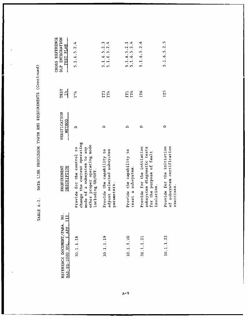
u0
C14 C14 C'j C4, CN .j
Lo~0l- PL4Lr) uLn Ul r r
4[-
E-4-' E- H- - E-4
-t 0
u' 0
J4.C:0 0E 0 0 4 0 0
-I O4 JQr4 040 )0 oc 041 00o
C)4 , - n-4 4 U 4 4) -
HZ Z E 41 r -4 ~ -4 . , 4- -4E4z 0 Q4 Q).4 -4 *,4J -4 0 ,-
z 0 .J4 a )E 0-4J
C- -4 ajU)0 4. C13 tv w~ 0JC
E 4 1-4 CJ2a,44 C 4)0 )' 1 CD C )
4: (n 0 ) 0.4 4-4 En j 0 0 04L0 W1 44 C Ca0 4) 4)J (n 44 Wr (-4 A V
4-) 4 g cfla) 0) 0a 4-4 0.-, 4) 4-) co) 4) 4 )-4 L) U (
C1 4))4 Q) > Cl > a) > m 4 > n
0 m "o c 0 14 0 (n 0 Q $ 0 0 a)
O CJE00 d 0J 0. Cd0$4 4.,4 0ul w 4)
4:P-
04
c0 -4 CZ -4 1-4 04. C')
C0 0C
0 r
A- 9
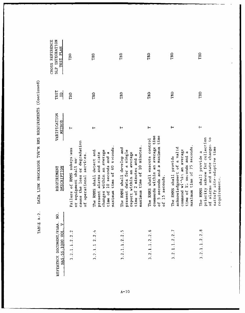
0aH
9z2
0o E-4 E-- E-4 I:
,-42
uwa E-4f~a
H Z - E-4 E- U. O Ca , a) a O'4-4 E flJ" OO4-
C)I-4E E!~f rCla 0 )
U) Efn C/) Enf~ ) d
o o a 2 1 2 -- o W o - 4o ( to oa .a En ca,1 co 0 o , -4e~ M 0 4 C -
SH - ) C 0r Cd 0)- OCw 4 >p10 Q )
c2.u t 0 - 0)U~ H a HOQ Cd5 -4 C > -(Z Hn -4 >
H . .
H> CNo CNI 44 CO C:
z .
0 1 -4 4) a) a)4 LO- -c 4 0 o
, 0N I4 I Io Iw I I
w ow rA ) -4 -4 Q 0 -4 4-4 -4-4 C -IV. I -
ce. Z4 E 4r:4( 4r44 t 4Q )"
CL4 0 CO 4 C Cn 0.) CO CA - 4 0 ) c - " 1 - (A (); a
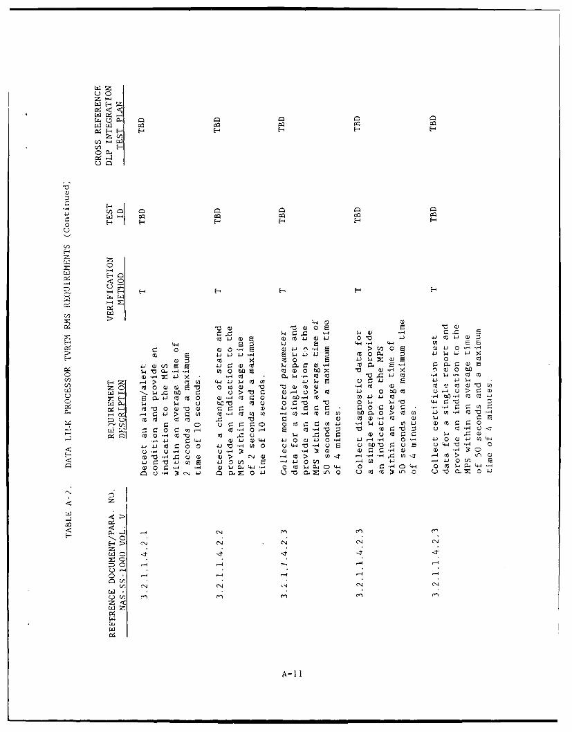
CzZ
cn -4Z
HE- HHHH
-e-
-4 4
C~ HC a) HH
E- 4404 i44- WuC: 0o . -- )44 , c )LC1 - J- E w 4)4 a 0 n4 : 1 4
(1 9 <0O04 wz ()s0 c
H -H v H ~ E H H. zI o 4P :4 oJL - 4a )F
I-e 't CL 4 - Ln 0 boE C (1 0 to xQ) 4 o 3) e i0 (1 .14z 41 x 4 Ctw - (a a a 4 4 -4M (
U) z 0 0 o 0 ) w 0 - wca a)"t 1 o 1) V
HZL4 4 0 t ptjI L44J.Ctsf uJ -j (: D0 " -i :-
Lz4 C ~ - 4 a l l-4C 7U qU) (0M U) bflo CLU 0~ > co (n 4 n- C I-
=) u- c cda ) a cc m) CJ.-:~ co4 4 - 4r
cli~ 0-m 0 Cl Q 4 a uc ta. C:a Uz =a
-4 U-4 U U-4 -4a) z~~ Q)~~ ) a) ,
Hu -AU) 3
>> cl 0) -4 CO > L t - U 4C
4- 0U -0 ,- 4 E- w 0 V-4En -14 . 0 C E0' -,4 - -4 -4) -4 a-4 A 0 C 4140 - - Z 4 -
-4 'N C 'N 4-'J 'Na 1 C)L)0 n 0tlz 0
CA-i
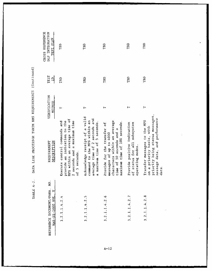
*0
0 -
z<
Cc~ w 0
a zJ0 4-4 bD ) zJ E -
20 4. (3 0 m a LEId C 4C z ., J nr
V) Q) -4 >ttU -4 0bf() 1 l a)4 )
4Jc 4, 4 Qfo- 0~ O ;0u c C-C9z LUC4 4.((1) 4.4 0 co 43) C.~ b V) 4,
Cl z v E 0 - C 7 0 o ,. )60V~ -4 ~ ) *J 0) * " z o (3-jJ)
lu > (1) z 4U. r W-4 > J - (Dci(
0a 0 )Q 1) a,~J 0. .0 )< 0 -, Q) Cd bw - C4 4 4 Z0 V -2 4 a) W0 H0 cn >. -
:4C& l 4 co ( t i) 4 0 E J 4 C
4J .- 0 -4 0 D-4 u b 1 z & 4- .-Z- -q 1 v( 4 - co c,44 1 A Mu o >f 4Q -4 > 0 4 O M
X (N PL4 (-6 uN 0 4a -4C 4 l, 4Z W 0
zZ
C14~~A 12U) -0
APPENDIX B
SAMPLE FORMS FOR DLP TESTING
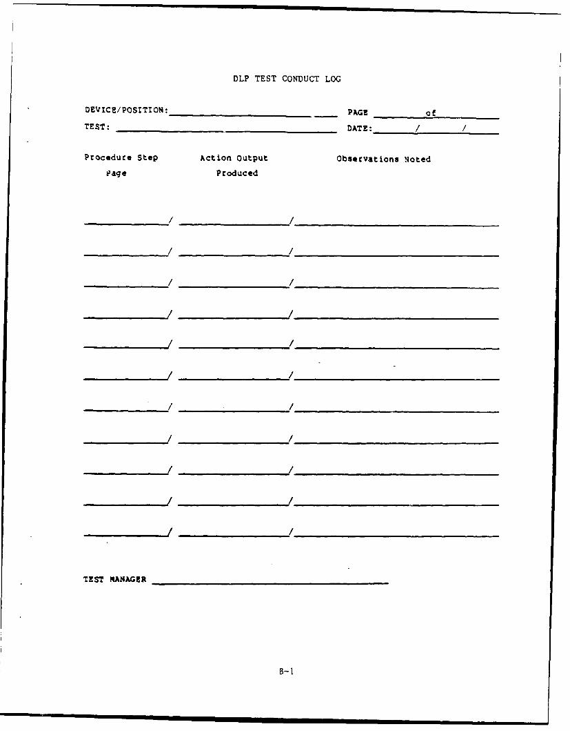
DLP TEST CONDUCT LOG
DEVICE/POSITION:______________ PAGE of
TEST: ______________________ DATE://
Procedure Step Action Output Observations Noted
Page Produced
TEST___ __ __ __ _ __ __ __ _ __ __
_ _ _ _ _ _ _ / _ _ _ _ _ _ _ _ / _ _ _ _ _ _ _ _ _ __B_ _ _
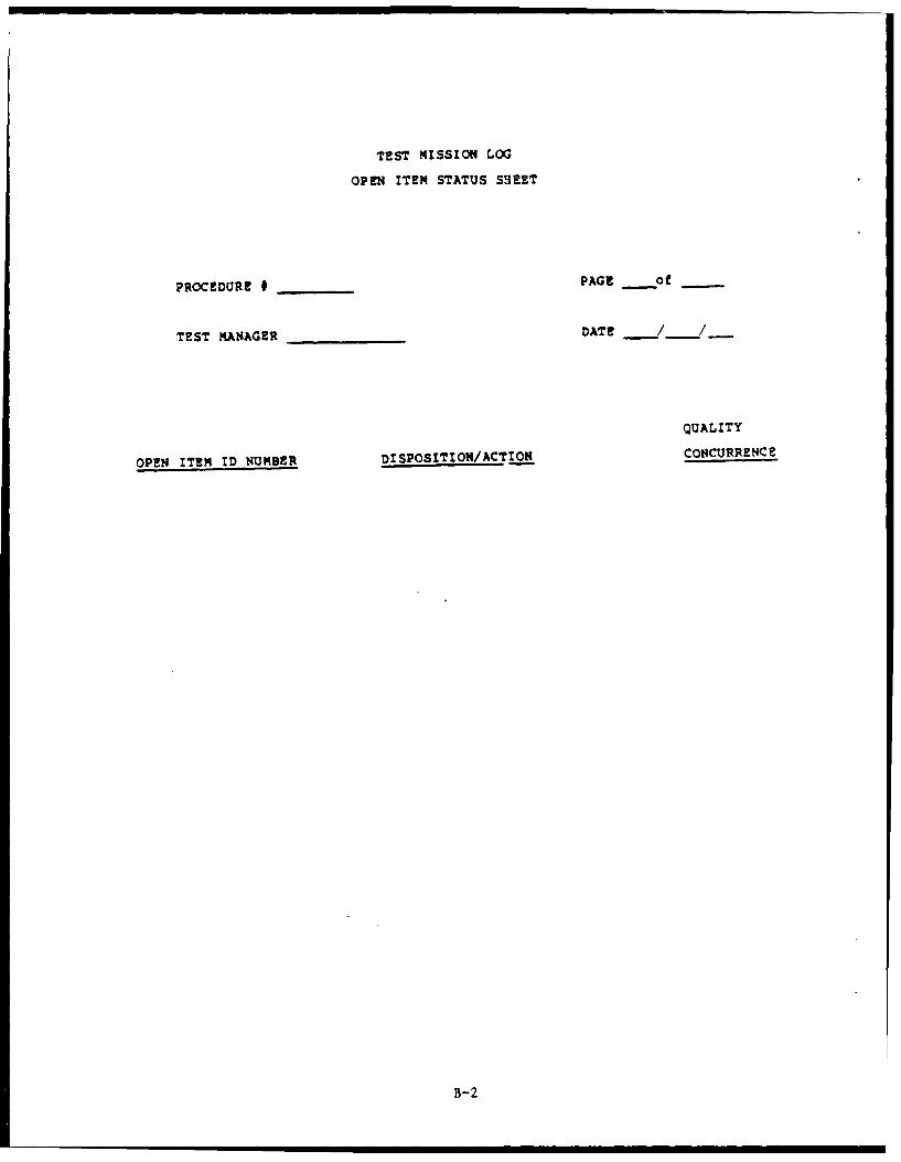
TEST MISSION LOG
OPEN ITEM STATUS SHEET
PROCEDURE # PAGE __o- -
TEST MANAGER DATE _/_/_
QUALITY
OPEN ITEM ID NUMBER DISPOSITION/ACTION CONCURRENCE
B-2
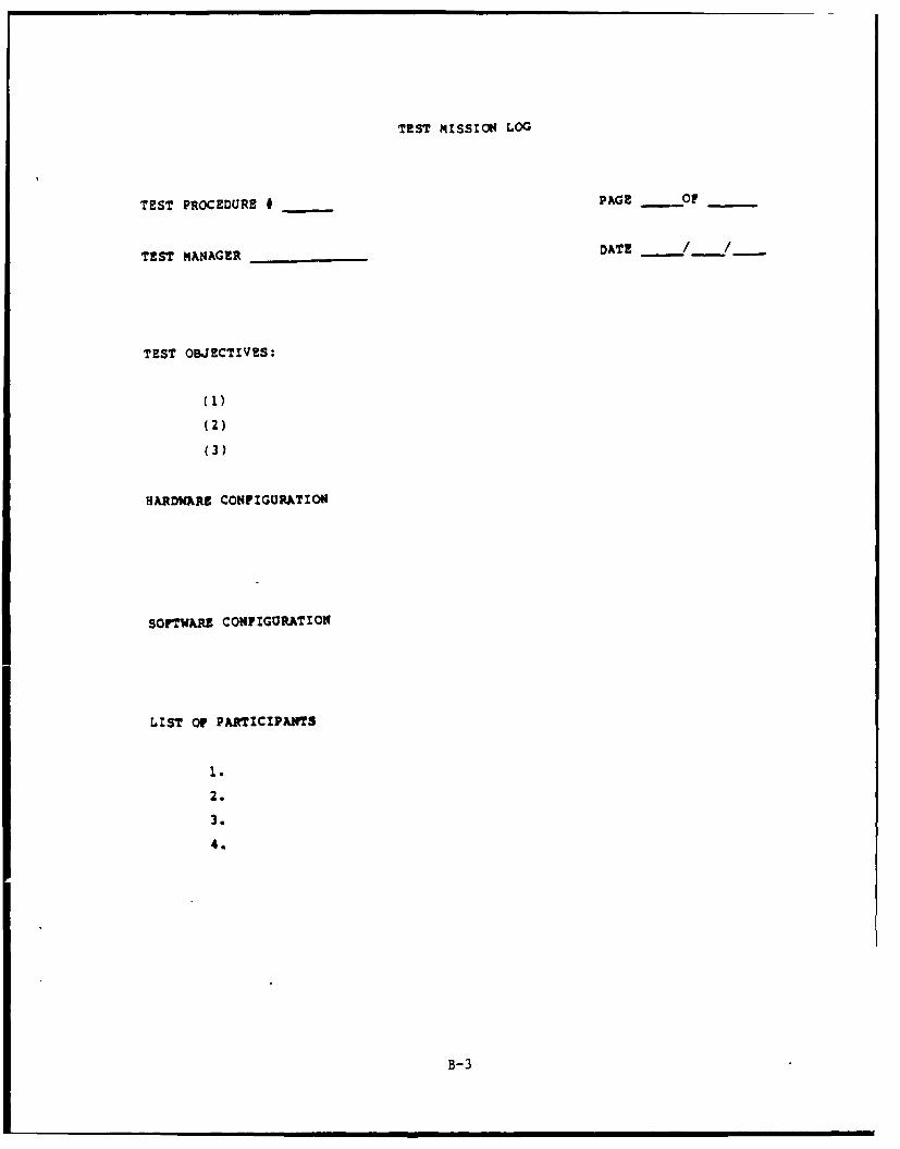
TEST MISSION LOG
TEST PROCEDURE * PAGE .OF
TEST MANAGER DATE / /
TEST OBJECTIVES:
(1)
(2)
(3)
HARDWARE CONFIGURATION
SOFTWARE CONFIGURATION
LIST Or PARTICIPANTS
1.
2.
3.
4.
B-3
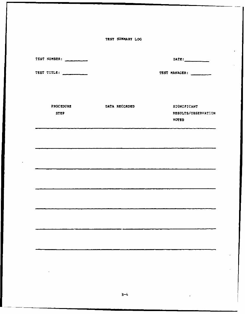
TEST SUMMqARY LOG
TEST NUMBER: ______DATE:______
TEST TITLE: ______TEST MANAGER: ____
PROCEDURE DATA RECORDED SIGNIFICANT
STEP RESULTS/OBSERVAT ION
NOTED
B-4
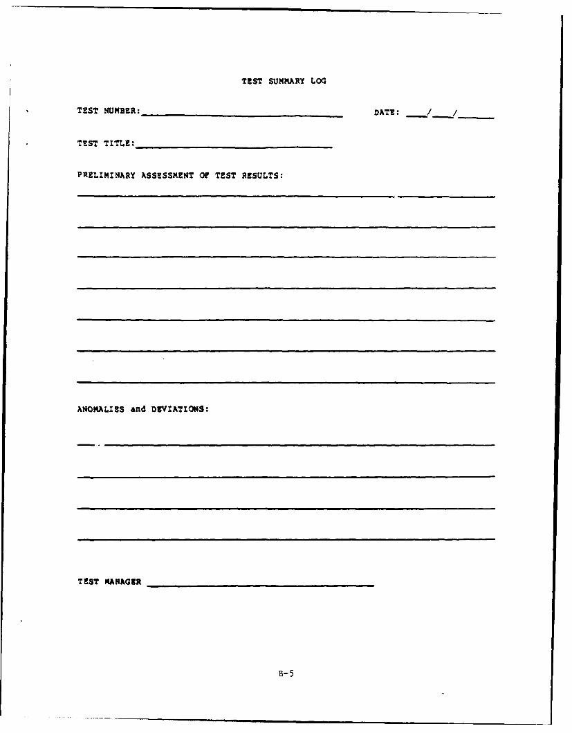
TEST SUMMARY LOG
TEST NUMBER_: DATE: / /
TEST TITLE:
PRELIMINARY ASSESSMENT OF TEST RESULTS:
ANOMALIES and DEVIATIONS:
TEST MANAGER
B-5
I
This page intentionally left blank.

F_7 DUPLICATE PTRPLEASE TYPE PROGRAM TECHNICAL REPORT EXITS
YE ITYPE OF REPORT TROUBLE TYPE OF FACILITY ENROUTE ORGANIZATION AF
IMPROVEMENT TER-INA, I AT1 2 3 4 S" 7 9 10 1114 15 16 17 is 19 20
PTR NUMBER ARTS SUSPECTED
O-t 1 .0NLY SU BP ROGRAM
SECTION MODEL VERSION 23 24 25 26 27 28 29 PRIORITYSYSTEM
TAPE 10
REFERENCE(S) ATTACHMENTS)
DESCRIPTION OF PROBLEM
ORIGINATOR*S SIGNATURE
ACTION TAKEN BY CENTRAL PROGRAMMING
CENTRAL PROGRAMMING USE ONLY FACILI TY USE ONLYDATE INITIALS GATE N ALS
PTR RECEIVED PTR RECEIVED FROM CENTRAL
PROGRAMMING
OTR DISTRIBUTED TO SITES PATCH AVAILABLE FOR USE
PATCH 4A5 AVAILABLE TO TEST PATCH VERIFIED
GROUP
PAT'H d[-41PIEIB BY TEST GROUP PATCH USED OPERATIONALLY
PATCH OISTRIBUTEO PATCH NUMBER
INDICATES SOURCE CODE IS GE-
VELOPED AND WILL BE ON THE SEE REVERSE SIDE FOR INSTRUCTIONSINDIC:ATEO SOURCE TAPE_
FAA Form 6100-1 12 7'
B-7
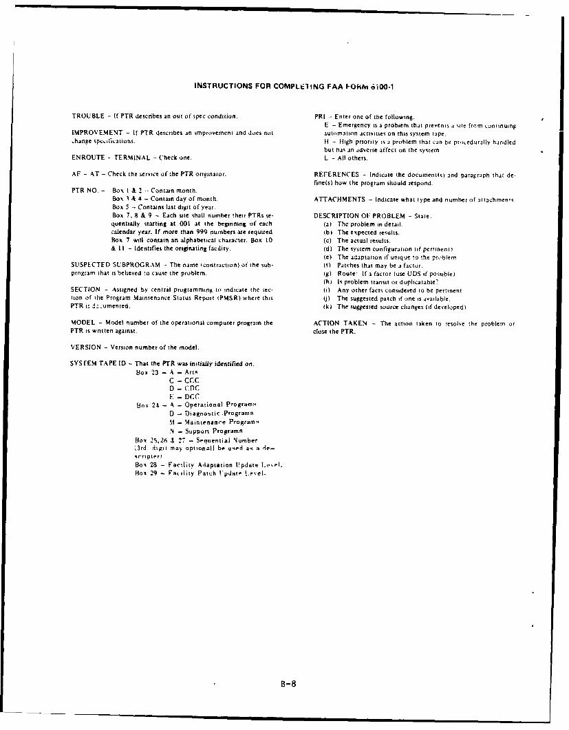
INSTRUCTIONS FOR COMPLEIING FAA IORM 6100-1
TROUBLE - If PTR describes an out of spec condition. PRI - Enter one of the following.E - Emergency is a problem that prevents ,i site from continuing
IMPROVEMENT - If PTR describes an improvement and does not automation activities on this system tape.change spc.ifiations. I - IHigh priority is a prohlem that can be procedurally handled
but has an adverse affect on the system.ENROUTE - TERMINAL - Check one. L - All others.
AF - AT - Check the service of the PTR orginator. REFERENCES - Indicate the documentis) and paragraph that de-fine(s) how the program should respond.
PTR NO. - Box I & 2 - Contain month.Box A 4 - Contain day of month. ATTACHMENTS - Indicate what type and number of attachmentsBox 5 - Contains last digit of year.Box 7. 8 & 9 - Each site shall numher their PTRs se- DESCRIPTION 01: PROBLEM - State:quentially starting at 001 at the beginning of each (a) The problem in detail.calendar year. If more than 999 numbers are required (b) The expected results.Box 7 will contain an alphabetical character. Box 10 (c The actual results.& I I - Identifies the originating facility. (d) The system configuration (if pertinent)
(e) The adaptation if unique to the probiemSUSPECTED SUBPROGRAM - The name (contraction) of the sub- If) Patches that may be a factor.program that is believed to cause the problem. ig) Route: If a factor (use UDS if possible)
(hi Is problem transit or duplicatable?SECTION - Assigned by central programming to indicate the sec- (I Any other facts considered to be pertinenttion of the Program Maintenance Status Report (PMSR) where this (j) The suggested patch if one is available.PTR i, -zumented. (k) The suggested source changes (if developed).
MODEL - Model number of the operational computer program the ACTION TAKEN - The action taken to resolve the problem orPTR is wntten against, close the PTR.
VERSION - Version number of the model.
SYSTEM TAPE ID - That the PTR was initially identified on:lBox 23 - A - Arts
C - CCCD - ('DCE - DCC
Box 24 - A - Operational ProgramsD - Diagnostic ProgransimM - Maintenance ProgramsN - Support Programs
Bos 2.5.26 & 27 - Sequiential Numberk3rd digit ma) optionall be used as a de-scripter)Box 28 - Facility Adaptation Update Iwel.Hox 29 - Fa lLity Patch Update Level.
B-8
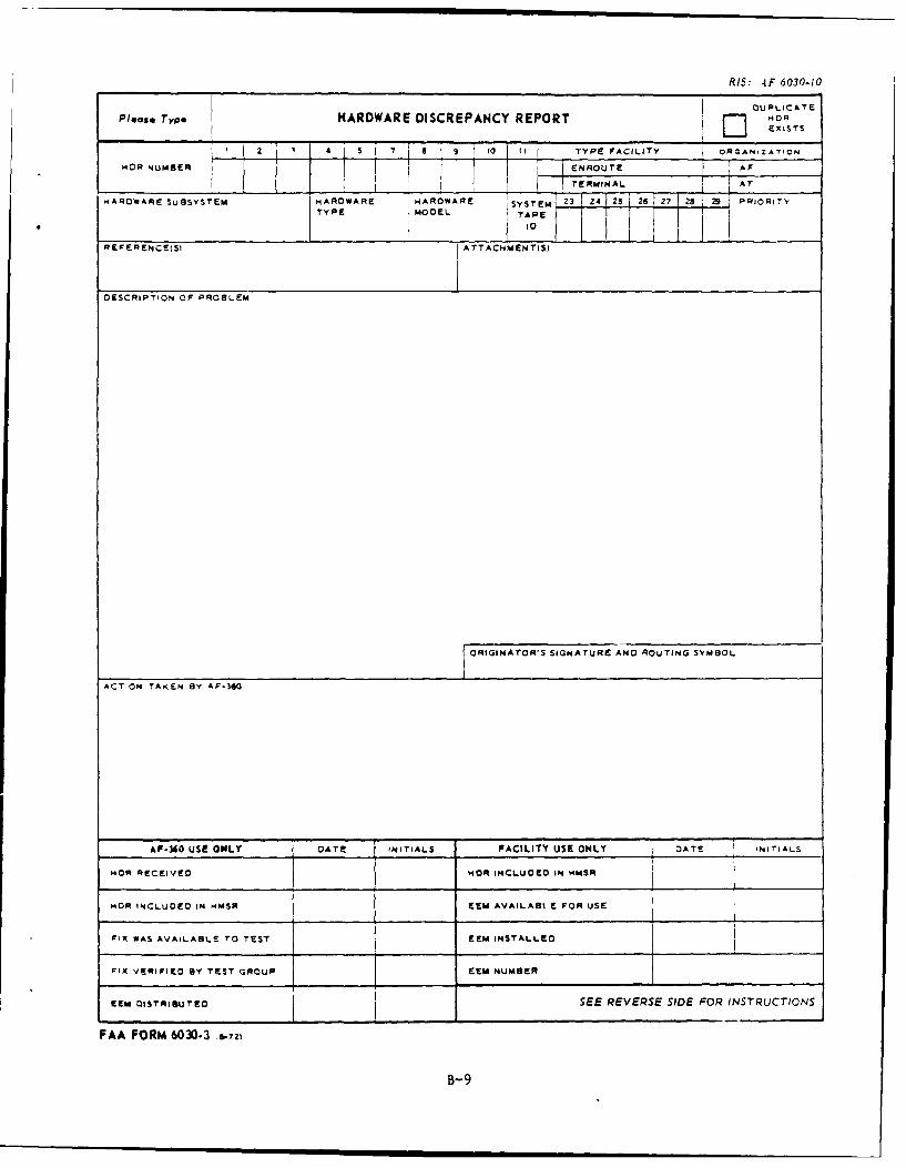
RIS: 4F 6030-10
D U PLICATE
PlOse Type HARDWARE DISCREPANCY REPORT - UOAEXISTS
to IU R ii TYPE FACILITY ORGANZATION
ROR NUMBER ENROUTE
.. .y OFAR2. SSY M A AE ____TERMINAL A
'ARDWARE SUBSYSTEM HARDWARE OHARWAR SYSTEM 3 24 23 26 28 2 2 PRIORITYT YCP E} O D E~ L T A PE~r
10
REFERENCESI ATTACHMENTIS)
DESCRIPTION OF PROBLEM
ORIGINATOR'S SIGNATURE ANO ROUTING SYMBOL
ACTION TAKEN BY AF-360
AF-360 USE ONLY GATE INITIALS FACILITY USE ONLY DATE INI TIALS
wOn RECEIVO NOR INCLUOEO IN NMSR
HOR INCLUDED IN -MSR (EM AVAILABI E FOR USE
FIX WAS AVAILABLE TO TEST EEM INSTALLED
FIX VERFIED BY TEST GROUP EEM NUMBER
FEM DISTRIBUTEO SEE REVERSE SIDE FOR INSTRUCTIONS
FAA FORM 6030.3 Sa.72i
B-9
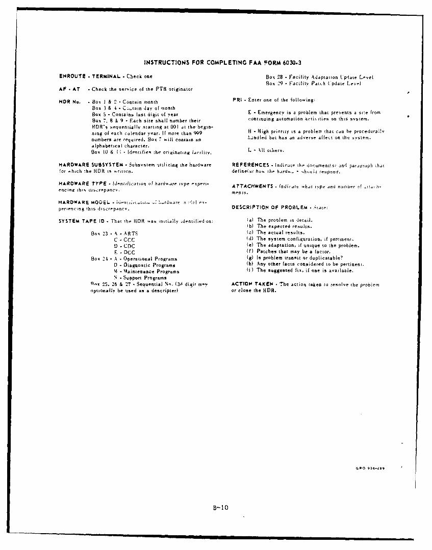
INSTRUCTIONS FOR COMPLETING FAA cORM 6030.3
ENROUTE - TERMINAL - Check one Box 28 - Facility Adaptation Update LevelBox 29 - Facility Patch Update Level
AF - AT - Check the service of the PTR originator
NOR No. - Box I & 2 - Contain month PRI - Enter one of the following:
Box 3 & 4 C .tain day of monthBox 5- Contains last digit uI year E - Emergency is a problem that prevents a site from
Box 7. 8 & 9 - Each site shall number their continuing automation actiities on this system.
HQR's sequentially starting at 001 at the begin-nina of each calendar year. If more than 999 H - High priority is a problem chat can be procedurally
numbers are required. Box 7 will contain an h.;ndled but has an adverse affect on the system.
alphabetical character.Box [0 & If Identifies the originating [Fcility. L - All oLliers.
HARDWARE SUBSYSTEM Subsystem utilizing the hardware REFERENCES - Indicate the locumenilsj and parjiaraph zhatfor which the HDR is ,ritten. define(s) ho, the hard%.- - houild respond.
HARDWARE TYPE - identification of hardware type expert- AtTACHMENTS - [ndicjta whjt type and number of ctj, hoencing this discrepancv. ments.
HARDWARE MOOEi - iienti,ci~zc-, -' .rd%%a-f7-!! xperiencing this discrepancy. DESCRIPTION OF PROBLEM - State:
SYSTEM TAPE ID - That the HDR -as initially identified on: (a) The problem in detail.
Ib) The expected results.Box 23 - A - ARTS fc) The actual results.
C - CCC (d) The system configuration, if pertinent.D - CDC Fe) The adaptation, if unique to the problem.E - DCC (f
) Patches that may be a factor.Box 24 - A -Operational Programs (g) Is problem transit or duplicatable?
D - Diagnostic Programs (h) Any other facts considered to be pertinent.%I -Maintenance Programs (i) The suggested fix, if one is available.N -Support Programs
A,lc 25, 26 & 27 - Sequential N.. (3 digit mv ACTION TAKEN • The action taken to resolve the problemoptionally be used as a descripter) or close the HDR.
GpO 436-29a
B_ 10