Embed Size (px)
Citation preview

ECMA-349 1st Edition - December 2003
Data Interchange on 120 mm and 80 mm Optical Disk using +R Format - Capacity: 4,7 and 1,46 Gbytes per Side (Recording speed up to 4X)


Data Interchange on 120 mm and 80 mm Optical Disk using +R Format - Capacity: 4,7 and 1,46 Gbytes per Side (Recording speed up to 4X)
Standard ECMA-349 1st Edition - December 2003
Ecma International Rue du Rhône 114 CH-1204 Geneva T/F: +41 22 849 6000/01 www.ecma-international.org
IW Ecma-349.doc 05.02.2004 16:07

.

Brief history
Ecma Technical Committee TC31 was established in 1984 for the standardization of Optical Disks and Optical Disk Cartridges (ODC). Since its establishment, the Committee has made major contributions to ISO/IEC toward the development of International Standards for 80 mm, 90 mm, 120 mm, 300 mm, and 356 mm media. Numerous standards have been developed by TC31 and published by Ecma, almost all of which have also been adopted by ISO/IEC under the fast-track procedure as International Standards.
In April 2003 a group of Companies proposed to TC31 to develop a standard for 120 mm recordable optical disks using the WORM recording technology and based on the DVD − Read-Only standard (ECMA-267) and the +RW format (ECMA-337). TC31 adopted this project and started the work that has resulted in this Ecma Standard.
This Ecma Standard specifies two Types of recordable optical disks, one (Type S) making use of recording on only a single side of the disk and yielding a nominal capacity of 4,7 or 1,46 Gbytes per disk and the other (Type D) making use of recording on both sides of the disk and yielding a nominal capacity of 9,4 or 2,92 Gbytes per disk.
This Ecma Standard, taken together with a standard for volume and file structure, such as for instance developed in Ecma Technical Committee TC15, provides the requirements for information interchange between systems.
The December 2003 General Assembly adopted this, 1st edition, of ECMA-349.


Table of contents
Section 1 - General 1
1 Scope 1
2 Conformance 1
2.1 Optical Disk 1 2.2 Generat ing system 1 2.3 Receiving system 1 2.4 Compat ib i l i ty statement 1
3 References 2
4 Definit ions 2
4.1 Channel b i t 2 4.2 Clamping Zone 2 4.3 Digi ta l Sum Value (DSV) 2 4.4 Disk Reference Plane 2 4.5 dummy substrate 2 4.6 entrance surface 2 4.7 f ie ld 2 4.8 groove 2 4.9 in ter leaving 2 4.10 mark 2 4.11 Mult i -session disk 2 4.12 Physical Sector 3 4.13 recording layer 3 4.14 Reed-Solomon code (RS) 3 4.15 Single-session disk 3 4.16 session 3 4.17 space 3 4.18 substrate 3 4.19 t rack 3 4.20 t rack pi tch 3 4.21 wobble 3 4.22 zone 3
- i -

5 Conventions and notations 3
5.1 Representat ion of numbers 3 5.2 Names 4
6 List of acronyms 4
7 General description of the optical disk 5
8 General Requirements 6
8.1 Environments 6 8.1.1 Test environment 6 8.1.2 Operat ing environment 6 8.1.3 Storage environment 6 8.1.4 Transportat ion 6
8.2 Safety requirements 6 8.3 Flammabi l i ty 6
9 Reference Drive 7
9.1 Optical system 7 9.2 Optical beam 7 9.3 Read channel 1 8 9.4 Disk c lamping 8 9.5 Rotat ion of the disk 9 9.6 Wobble channel (Read channel 2) 9 9.7 Tracking channel (Read channel 2) 9
9.7.1 Normal ized servo t ransfer funct ion 9 9.7.2 Reference Servo for Axia l Tracking 10 9.7.3 Reference Servo for Radial Tracking 11
Section 2 - Dimensional, mechanical and physical characterist ics of the disk 12
10 Dimensional characterist ics 12
10.1 Reference Planes 12 10.2 Overal l d imensions 12 10.3 First t ransi t ion area 13 10.4 Second t ransi t ion area 13 10.5 Clamping Zone 13 10.6 Third t ransi t ion area 13 10.7 Informat ion Zone 13 10.8 Rim Area 14 10.9 Remark on to lerances 14
- ii -
11 Mechanical characterist ics 16
11.1 Mass 16 11.2 Moment of inert ia 16 11.3 Dynamic imbalance 16 11.4 Axial runout 16 11.5 Radial runout 16
12 Optical characterist ics in the Information Zone 17
12.1 Index of refract ion 17 12.2 Thickness of the substrate 17 12.3 Reflect iv i ty 17 12.4 Birefr ingence 17 12.5 Angular deviat ion 18
Section 3 - Format of information 19
13 Data format 19
13.1 Data Frames 19 13.1.1 Ident i f icat ion Data ( ID) 20 13.1.2 ID Error Detect ion Code ( IED) 20 13.1.3 RSV 20 13.1.4 Error Detect ion Code (EDC) 21
13.2 Scrambled Frames 21 13.3 ECC Blocks 22 13.4 Recording Frames 23 13.5 Modulat ion and NRZI conversion 24 13.6 Physical Sectors 24 13.7 Layout of a Recording UNit (RUN) 26
13.7.1 Recording Uni t posi t ion 26 13.8 d.c. component suppression control 27
14 Track format 28
14.1 Track shape 28 14.2 Track path 28 14.3 Track pi tch 28 14.4 Track layout 28
14.4.1 ADIP informat ion 28 14.4.2 Physical format informat ion in ADIP 33
Section 4 - Format of the Information Zone 45
15 General description of the Information Zone 45 - iii -
16 Layout of the Information Zone of a Single-session disk 45
16.1 Physical Sector Numbers (PSNs) 45
17 Inner Drive Area 46
17.1 In i t ia l Zone 47 17.2 Inner Disk Test Zone 47 17.3 Count Zone Run- in 47 17.4 Inner Disk Count Zone 47 17.5 Inner Disk Administrat ion Zone 47 17.6 Table of Contents (TOC) Zone 48
17.6.1 Table of Contents Blocks 48 17.6.2 Recorded Area Indicators 51
18 Lead-in Zone 51
18.1 Guard Zone 1 51 18.2 Reserved Zone 1 51 18.3 Reserved Zone 2 52 18.4 Inner Disk Ident i f icat ion Zone 52 18.5 Reserved Zone 3 52 18.6 Reference Code Zone 52 18.7 Buffer Zone 1 53 18.8 Control Data Zone 53
18.8.1 Physical format informat ion 53 18.8.2 Disk manufactur ing informat ion 55 18.8.3 Content provider informat ion 55
18.9 Buffer Zone 2 55
19 Data Zone 55
20 Lead-out Zone 55
20.1 Buffer Zone 3 56 20.2 Outer Disk Ident i f icat ion Zone 56 20.3 Guard Zone 2 56
21 Outer Drive Area 56
21.1 Outer Disk Administrat ion Zone 57 21.2 Outer Disk Count Zone 57 21.3 Outer Disk Test Zone 57 21.4 Guard Zone 3 57
- iv -

22 Multi-session Layout 58
22.1 Intro 59 22.1.1 Buffer Zone A 59 22.1.2 Inner Session Ident i f icat ion Zone 59 22.1.3 Session Control Data Zone 59 22.1.4 Buffer Zone B 59
22.2 Data Zone 59 22.3 Closure 59
22.3.1 Buffer Zone C 59 22.3.2 Outer Session Ident i f icat ion Zone 59
23 Sequential recording in Fragments 60
23.1 Opening a Session 60 23.1.1 Incomplete Fragment 60 23.1.2 Reserved Fragments 60 23.1.3 Recording User Data in Fragments 61 23.1.4 Closing a Fragment 61
23.2 Closing a Session 62 23.2.1 Lead- in/ Intro Zone 62 23.2.2 Closure Zone 62
23.3 Final iz ing the disk 62
24 Assignment of Logical Sector Numbers (LSNs) 63
25 Disk Control Blocks 63
25.1 General format of Disk Control Blocks 63 25.2 Format of the Session DCB (SDCB) 64
25.2.1 Session I tems 66
Section 5 – Characterist ics of the groove 69
26 General 69
27 Method of testing 69
27.1 Environment 69 27.2 Reference Dr ive 69
27.2.1 Optics and mechanics 69 27.2.2 Read power 69 27.2.3 Read channels 69 27.2.4 Tracking 69
27.3 Def in i t ion of s ignals 70
28 Characterist ics of the groove signals 71
28.1 Phase depth 71 - v -

28.2 Push-pul l s ignal 71 28.3 Track Cross s ignal 71 28.4 Normal ized wobble s ignal 71 28.5 Character ist ics of the wobble 71
Section 6 - Characterist ics of the recording layer 72
29 Method of testing 72
29.1 Environment 72 29.2 Reference Dr ive 72
29.2.1 Optics and mechanics 72 29.2.2 Read power 72 29.2.3 Read channels 72 29.2.4 Tracking 72 29.2.5 Scanning veloci ty 72
29.3 Write condi t ions 73 29.3.1 Write pulse waveform 73 29.3.2 Write power 73 29.3.3 Write power dependency on wavelength 73 29.3.3 Write power window 73
29.4 Measurement condi t ions 74
30 Characterist ics of the recorded signals 75
30.1 Channel b i t length 75 30.2 Def in i t ion of s ignals 75
30.2.1 High f requency s ignals (HF) 75 30.2.2 Modulated ampl i tude 75 30.2.3 Signal asymmetry 76 30.2.4 Normal ized Sl ic ing Level jump 76 30.2.5 Ji t ter 76 30.2.6 Track Cross s ignal 76
30.3 Read stabi l i ty 76
31 Addit ional testing condit ions 77
31.1 Test environment 77 31.1.1 Optics 77
31.2 Def in i t ion of s ignals 77 31.2.1 Modulated ampl i tude 77 31.2.2 Signal asymmetry 77 31.2.3 Ji t ter 77 31.2.4 Track Cross s ignal 78 31.2.5 Dif ferent ia l phase t racking error s ignal 78 31.2.6 Tangent ia l push-pul l s ignal 79
- vi -

32 Quality of the recording layer 79
32.1 Defects 79 32.2 Data errors 79
Section 7 - Characterist ics of user data 80
33 Method of testing 80
33.1 Environment 80 33.2 Reference Dr ive 80
33.2.1 Optics and mechanics 80 33.2.2 Read power 80 33.2.3 Read channels 80 33.2.4 Error correct ion 80 33.2.5 Tracking 80
34 Minimum quality of a Recording Unit 81
34.1 Tracking 81 34.2 User-wr i t ten data 81
Annex A - 80 mm +R disk 83
Annex B - Measurement of l ight ref lectivity 87
Annex C - Measurement of birefr ingence 89
Annex D - Measuring condit ions for operation signals 91
Annex E - Measurement of the differential phase tracking error 95
Annex F - The write pulse wave form for testing 99
Annex G - 8-to-16 Modulation 105
Annex H - Optimum Power Control and Recording Condit ions 113
Annex I - Light fastness of the disk 117
Annex J - Wavelength dependency 119
Annex K - Running OPC 123
Annex L - Transportation 125
Annex M - Measurement of the groove wobble amplitude 127
- vii -

Annex N - How to use the Physical format information in ADIP 129
Annex O - Values to be Implemented in Existing and Future Specif ications 131
- viii -

Section 1 - General
1 Scope This Ecma Standard specifies the mechanical, physical and optical characteristics of 120 mm recordable optical disks with capacities of 4,7 Gbytes and 9,4 Gbytes. It specifies the quality of the recorded and unrecorded signals, the format of the data and the recording method, thereby allowing for information interchange by means of such disks. The data can be written once and read many times using a non-reversible method. These disks are identified as +R.
The +R system also allows 80 mm disks with capacities of 1,46 Gbytes and 2,92 Gbytes. These disks shall have the same characteristics as the 120 mm disks, except for some parameters related to the smaller dimensions. All parameters unique for the 80 mm disks are specified in Annex A.
This Ecma Standard specifies − two related but different Types of this disk (see Clause 7), − the conditions for conformance, − the environments in which the disk is to be tested, operated and stored, − the mechanical, physical and dimensional characteristics of the disk, so as to provide
mechanical interchange between data processing systems, − the format of the information on the disk, including the physical disposition of the tracks and
sectors, the error correcting codes and the coding method, − the characteristics of the signals recorded on the disk, thus enabling data processing systems to
read the data from the disk. This Ecma Standard provides for the interchange of disks between optical disk drives. Together with a standard for volume and file structure, it provides for full data interchange between data processing systems.
2 Conformance
2.1 Optical Disk A claim of conformance with this Ecma Standard shall specify the Type implemented. An optical disk shall be in conformance with this Ecma Standard if it meets all mandatory requirements specified for its Type.
2.2 Generating system A generating system shall be in conformance with this Ecma Standard if the optical disk it generates is in accordance with 2.1.
2.3 Receiving system A receiving system shall be in conformance with this Ecma Standard if it is able to handle both Types of optical disk according to 2.1.
2.4 Compatibility statement A claim of conformance by a Generating or Receiving system with this Ecma Standard shall include a statement listing any other standards supported. This statement shall specify the numbers of the standards, the optical disk types supported (where appropriate) and whether support includes reading only or both reading and writing.
- 1 -

3 References ECMA-43 8-bit Coded Character Set Structure and Rules, Third Edition (1991) (ISO/IEC 4873)
ECMA-267 120 mm DVD – Read-Only Disk (1997)
ECMA-268 80 mm DVD – Read-Only Disk (1997)
ECMA-287 Safety of Electronic Equipment (1999)
ECMA-337 Data Interchange on 120 mm and 80 mm Optical Disk using +RW Format (2003)
4 Definitions For the purpose of this Ecma Standard the following definitions apply:
4.1 Channel bit The elements by which the binary values ZERO and ONE are represented by marks and spaces on the disk.
4.2 Clamping Zone The annular part of the disk within which the clamping force is applied by the clamping device.
4.3 Digital Sum Value (DSV) The arithmetic sum obtained from a bit stream by allocating the decimal value +1 to bits set to ONE and the decimal value −1 to bits set to ZERO.
4.4 Disk Reference Plane A plane defined by the perfectly flat annular surface of an ideal spindle onto which the clamping Zone of the disk is clamped, and which is normal to the axis of rotation.
4.5 dummy substrate A layer which may be transparent or not, provided for the mechanical support of the disk and, in some cases, of the recording layer as well.
4.6 entrance surface The surface of the disk onto which the optical beam first impinges.
4.7 field A subdivision of a sector.
4.8 groove A trench-like feature of the disk, applied before the recording of any information, and used to define the track location. The groove is located nearer to the entrance surface than the so-called land in between the grooves. The recording is made on the groove.
4.9 interleaving The process of reallocating the physical sequence of units of data so as to render the data more immune to burst errors.
4.10 mark A non-reversible feature of the recording layer which may take the form of less reflective area, a pit, or any other type or form that can be sensed by the optical system. The pattern of marks and spaces represents the data on the disk.
4.11 Multi-session disk A disk containing more than one set of Lead-in/Intro, Data, and Lead-out/Closure Zones.
- 2 -

4.12 Physical Sector The smallest addressable part of a track in the Information Zone of a disk that can be accessed independently of other addressable parts of the Zone.
4.13 recording layer A layer of the disk on which data is written during manufacture and / or use.
4.14 Reed-Solomon code (RS) An error detection and / or correction code.
4.15 Single-session disk A disk containing a Lead-in Zone, one Data Zone, and a Lead-out Zone.
4.16 session A continuous part of the Information Zone of the disk consisting of a Lead-in or Intro Zone, a Data Zone and a Lead-out or Closure Zone.
4.17 space A feature of the recording layer represented by any area between two marks which can be sensed by the optical system. The pattern of marks and spaces represents the data on the disk.
4.18 substrate A transparent layer of the disk, provided for mechanical support of the recording layer, through which the optical beam accesses the recording layer.
4.19 track A 360° turn of a continuous spiral.
4.20 track pitch The distance between adjacent track centrelines, measured in a radial direction.
4.21 wobble A continuous sinusoidal deviation of the track from the average centreline. Location information is included as phase modulated data in the wobble.
4.22 zone An annular area of the disk.
5 Conventions and notations
5.1 Representation of numbers A measured value is rounded off to the least significant digit of the corresponding specified value. For instance, it implies that a specified value of 1,26 with a positive tolerance of +0,01 and a negative tolerance of -0,02 allows a range of measured values from 1,235 to 1,274.
Numbers in decimal notations are represented by the digits 0 to 9.
Numbers in hexadecimal notation are represented by the hexadecimal digits 0 to 9 and A to F in parentheses.
The setting of bits is denoted by ZERO and ONE.
Numbers in binary notations and bit patterns are represented by strings of digits 0 and 1, with the most significant bit shown to the left. In a pattern of n bits, bit b(n-1) shall be the most significant bit (msb) and bit b0 shall be the least significant bit (lsb). Bit b(n-1) shall be recorded first.
- 3 -

Negative values of numbers in binary notation are given as Two’s complement.
In each data field, the data is recorded so that the most significant byte (MSB), identified as Byte 0, shall be recorded first and the least significant byte (LSB) last.
In a field of 8n bits, bit b(8n-1) shall be the most significant bit (msb) and bit b0 the least significant bit (lsb). Bit b(8n-1) shall be recorded first.
5.2 Names The names of entities, e.g. specific tracks, fields, etc., are given with an initial capital.
6 List of acronyms a.c. alternating current ADIP Address in Pre-groove ASM Asymmetry BP Byte Position BPF Band Pass Filter CAV Constant Angular Velocity CLD Constant Linear Density CLV Constant Linear Velocity cm current mark d.c. direct current DCB Disk Control Block DCC d.c. Component suppression Control DSV Digital Sum Value ECC Error Correction Code EDC Error Detection Code EI Extended Information HF High Frequency ID Identification Data IED ID Error Detection code LPF Low Pass filter LSN Logical Sector Number lsb Least Significant Bit LSB Least Significant Byte msb Most Significant Bit MSB Most Significant Byte NA Numerical Aperture NRZ Non Return to Zero NRZI Non Return to Zero Inverted NSL Normalized Slicing Level NWPW Normalized Write Power Window OPC Optimum Power Control PAA Physical Address in ADIP PBS Polarizing Beam Splitter PI Parity of Inner-code PLL Phase Locked Loop PP Push-Pull pp peak-to-peak ps previous space PSN Physical Sector Number
- 4 -
PO Parity of Outer-code RIN Relative Intensity Noise RS Reed-Solomon code RSV Reserved (in use by specific applications) RUN Recording UNit SDCB Session DCB SNR Signal to Noise Ratio SYNC Synchronization code TOC Table of Contents
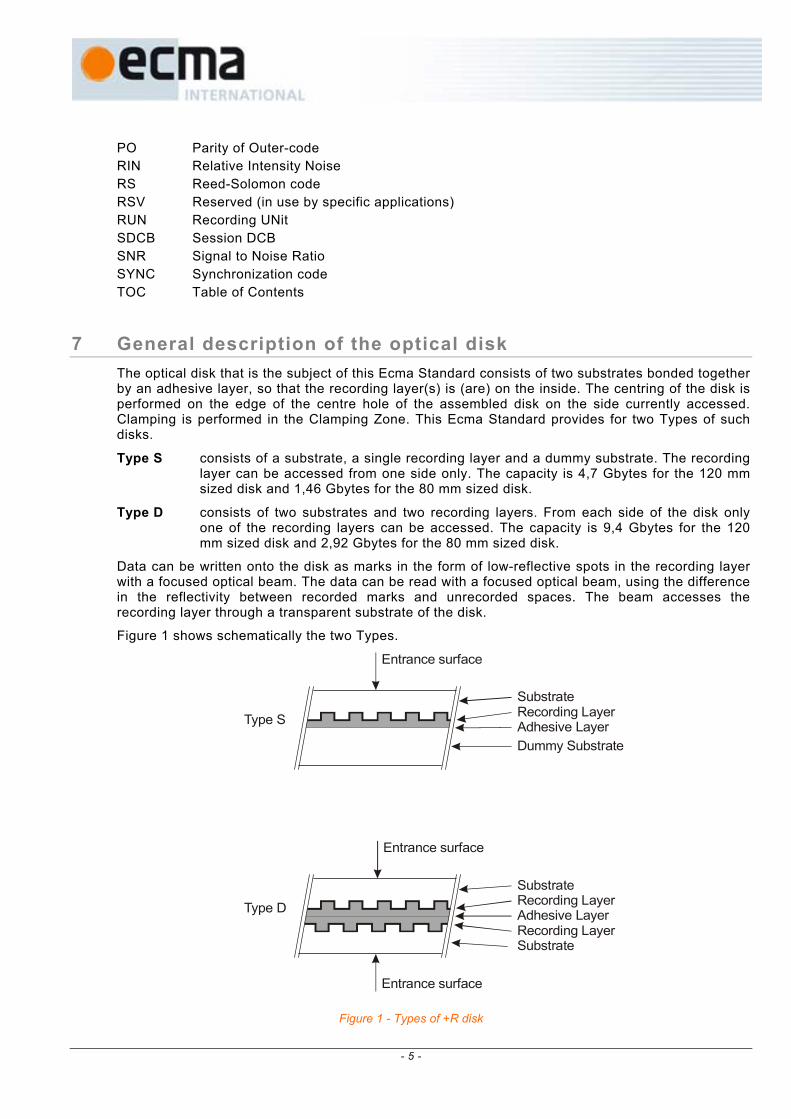
7 General description of the optical disk The optical disk that is the subject of this Ecma Standard consists of two substrates bonded together by an adhesive layer, so that the recording layer(s) is (are) on the inside. The centring of the disk is performed on the edge of the centre hole of the assembled disk on the side currently accessed. Clamping is performed in the Clamping Zone. This Ecma Standard provides for two Types of such disks.
Type S consists of a substrate, a single recording layer and a dummy substrate. The recording layer can be accessed from one side only. The capacity is 4,7 Gbytes for the 120 mm sized disk and 1,46 Gbytes for the 80 mm sized disk.
Type D consists of two substrates and two recording layers. From each side of the disk only one of the recording layers can be accessed. The capacity is 9,4 Gbytes for the 120 mm sized disk and 2,92 Gbytes for the 80 mm sized disk.
Data can be written onto the disk as marks in the form of low-reflective spots in the recording layer with a focused optical beam. The data can be read with a focused optical beam, using the difference in the reflectivity between recorded marks and unrecorded spaces. The beam accesses the recording layer through a transparent substrate of the disk.
Figure 1 shows schematically the two Types.
Type S
Type D
Substrate
Substrate
Recording Layer
Recording Layer
Recording Layer
Adhesive Layer
Adhesive Layer
Dummy Substrate
Substrate
Entrance surface
Entrance surface
Entrance surface
Figure 1 - Types of +R disk
- 5 -

8 General Requirements
8.1 Environments 8.1.1 Test environment
In the test environment, the air immediately surrounding the disk shall have the following properties:
temperature : 23 °C ± 2 °C relative humidity : 45 % to 55 % atmospheric pressure : 60 kPa to 106 kPa No condensation on the disk shall occur. Before testing, the disk shall be conditioned in this environment for 48 h minimum. It is recommended that, before testing, the entrance surface of the disk shall be cleaned according to the instructions of the manufacturer of the disk.
Unless otherwise stated, all tests and measurements shall be made in this test environment.
8.1.2 Operating environment This Ecma Standard requires that a disk which meets all requirements of this Ecma Standard in the specified test environment shall provide data interchange over the specified ranges of environmental parameters in the operating environment.
The operating environment is the environment where the air immediately surrounding the disk shall have the following properties:
temperature : 5 °C to 55 °C relative humidity : 3 % to 85 % absolute humidity : 1 g/m3 to 30 g/m3
atmospheric pressure : 60 kPa to 106 kPa temperature gradient : 10 °C/h max. relative humidity gradient : 10 %/h max.
No condensation on the disk shall occur. If the disk has been exposed to conditions outside those specified in this Clause, it shall be acclimatized in an allowed operating environment for at least 2 h before use.
8.1.3 Storage environment The storage environment is defined as the environment where the air immediately surrounding the disk shall have the following properties:
temperature : -10 °C to 55 °C relative humidity : 3 % to 90 % absolute humidity : 1 g/m3 to 30 g/m3 atmospheric pressure : 60 kPa to 106 kPa temperature gradient : 15 °C/h max. relative humidity gradient : 10 %/h max.
No condensation on the disk shall occur.
8.1.4 Transportation This Ecma Standard does not specify requirements for transportation; guidance is given in Annex L.
8.2 Safety requirements The disk shall satisfy the safety requirements of Standard ECMA-287, when used in the intended manner or in any foreseeable use in an information processing system.
8.3 Flammability The disk and its components shall be made from materials that comply with the flammability class for HB materials, or better, as specified in Standard ECMA-287.
- 6 -

9 Reference Drive The Reference Drive shall be used for the measurement of optical parameters for conformance with the requirements of this Ecma Standard. The critical components of this device have the characteristics specified in this Clause.
9.1 Optical system The basic set-up of the optical system of the Reference Drive used for measuring the write and read parameters is shown in Figure 2. Different components and locations of components are permitted, provided that the performance remains the same as that of the set-up in Figure 2. The optical system shall be such that the detected light reflected from the entrance surface of the disk is minimized so as not to influence the accuracy of the measurements.
++
+-
++
++
Read Channel 2
Read Channel 1H1
H4
H3
H2
A Laser diodeB Collimator lensC Polarizing beam splitterD Quarter-wave plateE Objective lens
BA C D EF
F Optical discG 4 quadrant photo detectorH H H H
H H
1 2 3 4a b c d 1 2 3 4
, , , d.c. coupled amplifiers, , , Output currents from photo detector G, Summed output currents of ,
I I I II I
G
G
Tangentialtrack
direction
Figure 2 - Optical system of the Reference Drive
The combination of a polarizing beam splitter C and a quarter-wave plate D shall separate the entrance optical beam from the laser diode A and the reflected optical beam from the disk F. The beam splitter C shall have a p-s intensity reflectance ratio of at least 100.
9.2 Optical beam The focused optical beam used for writing and reading data shall have the following properties:
a) Wavelength (λ) (see Annex J) nm5
nm10nm655
−
+
b) Numerical aperture of the objective lens (NA) 0,65 ± 0,01
c) The objective lens shall be compensated for spherical aberrations caused by a parallel substrate with nominal thickness (0,6 mm) and nominal refractive index (1,55).
d) Wave front aberration 0,033 × λ rms max.
e) Light intensity at the rim of the pupil of the 35 % to 50 % of the maximum intensity objective lens in the radial direction and 45 % to 60 % in the tangential direction.
- 7 -

f) Polarization of the light Circular
g) Read power (average) 0,7 mW ± 0,1 mW (d.c. or HF modulated with a frequency >400 MHz)
h) Write power and pulse width see Annex F
i) Relative Intensity Noise (RIN)* of the laser diode -134 dB/Hz max.
*RIN (dB/Hz) = 10 log [(a.c. light power density / Hz) / d.c. light power]
9.3 Read channel 1 Read channel 1 shall be provided to generate signals from the marks and spaces in the recording layer. This Read channel shall be used for reading the user-written information, using the change in reflectivity of the marks and spaces. The read amplifiers after the photo detectors in the Read channel shall have a flat response within 1 dB from d.c. to 20 MHz.
For measurement of jitter, the characteristics of the PLL and the slicer, etc. are specified in Annex D.
9.4 Disk clamping For measuring, the disk shall be clamped between two concentric rings covering most of the Clamping Zone (see 10.5). The top clamping area shall have the same diameters as the bottom clamping area (Figure 3). Clamping shall occur between
mm0,0
mm0,5in mm22,3
−
+=d
and
mm0,5
mm0,0out mm32,7
−
+=d
disk
dout
din
F1 F1
F2
α
Figure 3 - Clamping and chucking conditions
The total clamping force shall be F1 = 2,0 N ± 0,5 N. In order to prevent warping of the disk under the moment of force generated by the clamping force and the chucking force F2 exerted on the rim of the centre hole of the disk, F2 shall not exceed 0,5 N (see Figure 3).
The tapered cone angle, α, shall be 40,0° ± 0,5°.
- 8 -

9.5 Rotation of the disk The actual rotation speed for reading the disk shall be such that it results in the Reference velocity of 3,49 m/s ± 0,03 m/s at the nominal Channel bit rate of 26,156 25 Mbit/s. The direction of rotation shall be counter-clockwise when viewed from the objective lens.
The actual rotation speed for writing the disk shall be such that it includes all Primary and Upper velocities for which parameters are specified in the Physical format information in the ADIP Aux Frames in the Lead-in Zone of the disk (see 14.4.1.1 and 14.4.2).
9.6 Wobble channel (Read channel 2) Read channel 2 of the drive provides the wobble signals to control the access to addressed locations on the disk during writing. The wobble signal is generated in Read Channel 2 as a signal (I1 - I2) related to the difference in the amount of light in the two halves of the exit pupil of the objective lens. The read amplifiers after the photo detectors in the Read channel shall have a flat response within 1 dB from d.c. to 20 MHz.
9.7 Tracking channel (Read channel 2) Read channel 2 of the drive provides the tracking error signals to control the servos for radial tracking of the optical beam. The radial tracking error is generated in Read Channel 2 as a signal (I1 - I2) related to the difference in the amount of light in the two halves of the exit pupil of the objective lens.
The method of generating the axial tracking error is not specified for the Reference Drive.
9.7.1 Normalized servo transfer function The open-loop transfer function, Hs(iω) for the axial and radial tracking servos is given by equation (1),
0
02
0s
3i1
3i1
i31)(iH
ω+
ω+
×
ω
×= ω
ω
ωω (1)
where
1i −=
ω = 2π f
ω0 = 2π f0
and f0 is the 0 dB crossover frequency of the open-loop transfer function. The crossover frequencies of the lead-lag network of the servo are
lead break frequency: f1 = f0 / 3
lag break frequency: f2 = f0 × 3
- 9 -
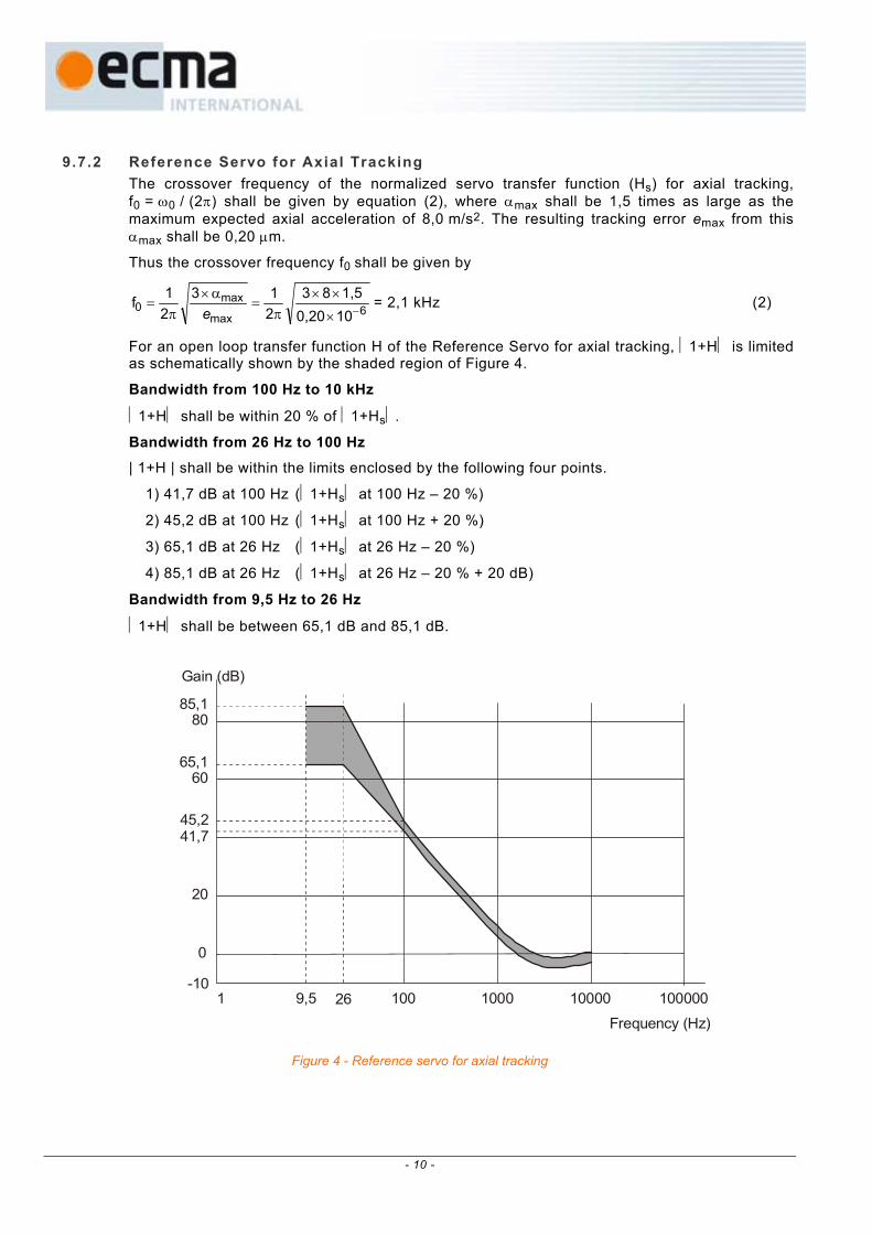
9.7.2 Reference Servo for Axial Tracking The crossover frequency of the normalized servo transfer function (Hs) for axial tracking, f0 = ω0 / (2π) shall be given by equation (2), where αmax shall be 1,5 times as large as the maximum expected axial acceleration of 8,0 m/s2. The resulting tracking error emax from this αmax shall be 0,20 µm.
Thus the crossover frequency f0 shall be given by
6max
max0
100,201,583
213
21f
−×
××π
=α×
π=
e= 2,1 kHz (2)
For an open loop transfer function H of the Reference Servo for axial tracking, 1+H is limited as schematically shown by the shaded region of Figure 4.
Bandwidth from 100 Hz to 10 kHz
1+H shall be within 20 % of 1+Hs.
Bandwidth from 26 Hz to 100 Hz
| 1+H | shall be within the limits enclosed by the following four points.
1) 41,7 dB at 100 Hz (1+Hs at 100 Hz – 20 %)
2) 45,2 dB at 100 Hz (1+Hs at 100 Hz + 20 %)
3) 65,1 dB at 26 Hz (1+Hs at 26 Hz – 20 %)
4) 85,1 dB at 26 Hz (1+Hs at 26 Hz – 20 % + 20 dB)
Bandwidth from 9,5 Hz to 26 Hz
1+H shall be between 65,1 dB and 85,1 dB.
Gain (dB)
85,180
65,160
45,241,7
20
0
1 100 1000 10000 1000009,5 26Frequency (Hz)
-10
Figure 4 - Reference servo for axial tracking
- 10 -

9.7.3 Reference Servo for Radial Tracking The crossover frequency of the normalized servo transfer function (Hs) for radial tracking f0 = ω0 / (2π) shall be given by equation (3), where αmax shall be 1,5 times as large as the maximum expected radial acceleration of 1,1 m/s2. The resulting tracking error emax from this αmax shall be 0,022 µm.
Thus the crossover frequency f0 shall be given by
6max
max0
100,0221,51,13
213
21f
−×
××π
=α×
π=
e= 2,4 kHz (3)
For an open loop transfer function H of the Reference Servo for radial tracking, 1+H is limited as schematically shown by the shaded region of Figure 5.
Bandwidth from 100 Hz to 10 kHz
1+H shall be within 20 % of1+Hs.
Bandwidth from 28,2 Hz to 100 Hz
1+H shall be within the limits enclosed by the following four points.
1) 43,7 dB at 100 Hz (1+Hs at 100 Hz – 20 %)
2) 47,2 dB at 100 Hz (1+Hs at 100 Hz + 20 %)
3) 65,6 dB at 28,2 Hz (1+Hs at 28,2 Hz – 20 %)
4) 85,6 dB at 28,2 Hz (1+Hs at 28,2 Hz – 20 % + 20 dB)
Bandwidth from 9,5 Hz to 28,2 Hz
1+H shall be between 65,6 dB and 85,6 dB.
Gain (dB)
85,680
65,660
47,243,7
20
0
1 100 1000 10000 1000009,5 28,2Frequency (Hz)
-10
Figure 5 - Reference servo for radial tracking
- 11 -

Section 2 - Dimensional, mechanical and physical characteristics of the disk
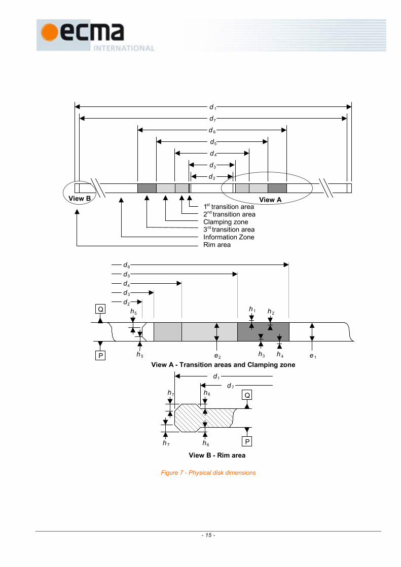
10 Dimensional characteristics Dimensional characteristics are specified for those parameters deemed mandatory for interchange and compatible use of the disk. Where there is freedom of design, only the functional characteristics of the elements described are indicated. The enclosed drawing, Figure 7 shows the dimensional requirements in summarized form. The different parts of the disk are described from the centre hole to the outside rim.
10.1 Reference Planes The dimensions are referred to two Reference Planes P and Q.
Reference Plane P is the primary Reference Plane. It is the plane on which the bottom surface of the Clamping Zone rests (see 10.5).
Reference Plane Q is the plane parallel to Reference Plane P at the height of the top surface of the Clamping Zone.
10.2 Overall dimensions The disk shall have an overall diameter (see also Annex A)
d1 = 120,00 mm ± 0,30 mm
The centre hole of a substrate or a dummy substrate shall have a diameter (see Figure 6)
mm0,00
mm0,15substrate mm15,00
−
+=d
The hole of an assembled disk, i.e. with both parts bonded together, shall have a diameter
d2 = 15,00 mm min.
dsubstrate
dsubstrated2
Figure 6 - Hole diameters for an assembled disk
The corners of the centre hole shall be free of any burrs or sharp features and shall be rounded off or chamfered by
h5 = 0,1 mm max.
- 12 -

The thickness of the disk shall be
mm0,06
mm0,301 mm1,20
−
+=e
10.3 First transition area In the area defined by d2 and
d3 = 16,0 mm min.
the surface of the disk is permitted to be above Reference Plane P and/or below Reference Plane Q by 0,10 mm max.
10.4 Second transition area This area shall extend between diameter d3 and diameter
d4 = 22,0 mm max.
In this area the disk may have an uneven surface or burrs up to 0,05 mm max. beyond Reference Planes P and/or Q.
10.5 Clamping Zone This Zone shall extend between diameter d4 and diameter
d5 = 33,0 mm min.
Each side of the Clamping Zone shall be flat within 0,1 mm. The top side of the Clamping Zone, i.e. that of Reference Plane Q shall be parallel to the bottom side, i.e. that of Reference Plane P within 0,1 mm.
In the Clamping Zone the thickness e2 of the disk shall be
mm0,10
mm0,202 mm1,20
−
+=e
10.6 Third transition area This area shall extend between diameter d5 and diameter
d6 = 44,0 mm max.
In this area the top surface is permitted to be above Reference Plane Q by
h1 = 0,25 mm max.
or below Reference Plane Q by
h2 = 0,10 mm max.
The bottom surface is permitted to be above Reference Plane P by
h3 = 0,10 mm max.
or below Reference Plane P by
h4 = 0,25 mm max.
10.7 Information Zone The Information Zone shall extend from diameter d6 to diameter (see also Annex A)
d7 = 117,5 mm min.
This Zone consists of the Lead-in Zone, the Data Zone, the Lead-out Zone and the Inner and Outer Drive Areas (see also Clause 15).
- 13 -

10.8 Rim Area The rim area is that area extending from diameter d7 to diameter d1. In this area the surfaces are permitted to both extend beyond Reference Plane Q or Reference Plane P
h6 = 0,1 mm max.
The outer corners of the disk shall be free of any burrs or sharp features and shall be rounded off or chamfered by
h7 = 0,2 mm max.
10.9 Remark on tolerances All heights specified in the preceding clauses and indicated by hi are independent from each other. This means that, for example, if the top surface of the third transition area is below Reference Plane Q by up to h2, there is no implication that the bottom surface of this area has to be above Reference Plane P by up to h3. Where dimensions have the same - generally maximum - numerical value, this does not imply that the actual values have to be identical.
- 14 -
d3
d4
d5
d6
d2
e2 e 1h3 h 4
h 2h 1
View A - Transition areas and Clamping zone
d3
d 4
d5
d 6
d2
1st transition area2nd transition areaClamping zone3rd transition areaInformation ZoneRim area
d 1
View A
d7
h6h 7
h7 h6
d1
d 7
h 5
h5
View B - Rim area
View B
Q
Q
P
P
Figure 7 - Physical disk dimensions
- 15 -

11 Mechanical characteristics
11.1 Mass The mass of the disk shall be in the range of 13,0 g to 20,0 g (see also Annex A).
11.2 Moment of inertia The moment of inertia of the disk, relative to its rotation axis, shall not exceed 0,040 g⋅m2 (see also Annex A).
11.3 Dynamic imbalance The dynamic imbalance of the disk, relative to its rotation axis, shall not exceed 2,5 g⋅mm (see also Annex A).
11.4 Axial runout When measured by the optical system with the Reference Servo for axial tracking, the disk rotating at the Reference velocity of 3,49 m/s (see 9.5), the deviation of the recording layer from its nominal position in the direction normal to the Reference Planes shall not exceed 0,3 mm.
The residual tracking error below 10 kHz, measured using the Reference Servo for axial tracking and the disk rotating at the Reference velocity, shall not exceed 0,13 µm. The measuring filter shall be a Butterworth LPF,
fc (-3 dB): 10 kHz, with slope : -80 dB/decade.
11.5 Radial runout The runout of the outer edge of the disk shall not exceed 0,3 mm peak-to-peak.
The radial runout of tracks shall not exceed 70 µm peak-to-peak.
The residual tracking error below 1,1 kHz, measured using the Reference Servo for radial tracking and the disk rotating at the Reference velocity of 3,49 m/s (see 9.5), shall not exceed 0,015 µm. The measuring filter shall be a Butterworth LPF,
fc (-3 dB) : 1,1 kHz, with slope : -80 dB/decade.
The rms noise value of the residual error signal in the frequency band from 1,1 kHz to 10 kHz, measured with an integration time of 20 ms, using the Reference Servo for radial tracking, shall not exceed 0,016 µm. The measuring filter shall be a Butterworth BPF,
frequency range (-3 dB) : 1,1 kHz, with slope : +80 dB/decade to : 10 kHz, with slope : -80 dB/decade.
- 16 -
12 Optical characteristics in the Information Zone
12.1 Index of refraction The index of refraction of the substrate in the Information Zone shall be 1,55 ± 0,10.
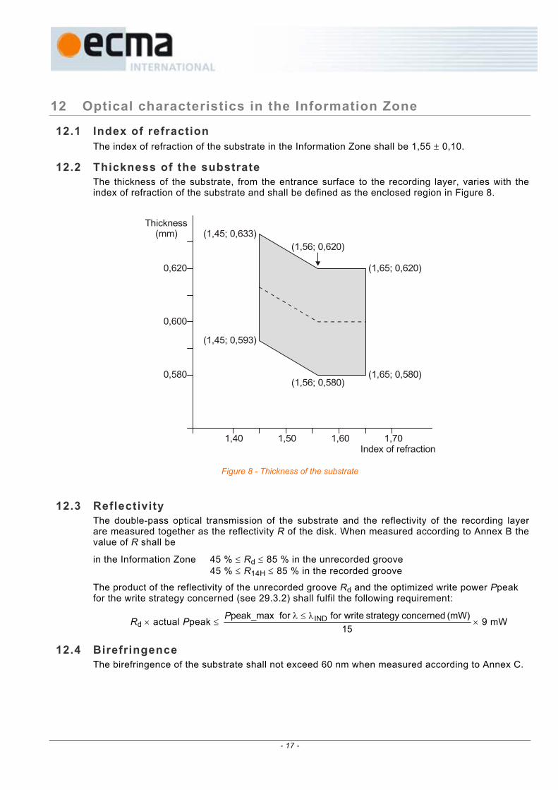
12.2 Thickness of the substrate The thickness of the substrate, from the entrance surface to the recording layer, varies with the index of refraction of the substrate and shall be defined as the enclosed region in Figure 8.
1,40 1,50 1,60 1,70
0,600
0,580
0,620
(1,45; 0,633)(1,56; 0,620)
(1,65; 0,620)
(1,45; 0,593)
(1,56; 0,580)(1,65; 0,580)
Thickness (mm)
Index of refraction
Figure 8 - Thickness of the substrate
12.3 Reflectivity
The double-pass optical transmission of the substrate and the reflectivity of the recording layer are measured together as the reflectivity R of the disk. When measured according to Annex B the value of R shall be
in the Information Zone 45 % ≤ Rd ≤ 85 % in the unrecorded groove 45 % ≤ R14H ≤ 85 % in the recorded groove
The product of the reflectivity of the unrecorded groove Rd and the optimized write power Ppeak for the write strategy concerned (see 29.3.2) shall fulfil the following requirement:
Rd × actual Ppeak ≤ 15
(mW) concernedstrategy writefor forpeak_max INDλ≤λP× 9 mW
12.4 Birefringence The birefringence of the substrate shall not exceed 60 nm when measured according to Annex C.
- 17 -
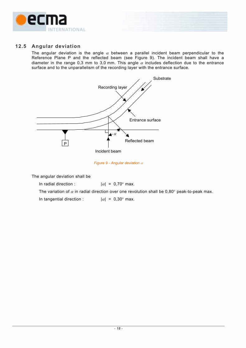
12.5 Angular deviation The angular deviation is the angle α between a parallel incident beam perpendicular to the Reference Plane P and the reflected beam (see Figure 9). The incident beam shall have a diameter in the range 0,3 mm to 3,0 mm. This angle α includes deflection due to the entrance surface and to the unparallelism of the recording layer with the entrance surface.
α
Incident beam
Reflected beam
Entrance surface
Substrate
Recording layer
P
Figure 9 - Angular deviation α
The angular deviation shall be
In radial direction : |α| = 0,70° max.
The variation of α in radial direction over one revolution shall be 0,80° peak-to-peak max.
In tangential direction : |α| = 0,30° max.
- 18 -

Section 3 - Format of information
13 Data format The data received from the host, called Main Data, is formatted in a number of steps before being recorded on the disk.
It is transformed successively into
− a Data Frame,
− a Scrambled Frame,
− an ECC Block,
− 16 Recording Frames,
− 16 Physical Sectors,
− a Recording Unit.
These steps are specified in the following clauses.
13.1 Data Frames A Data Frame shall consist of 2 064 bytes arranged in an array of 12 rows each containing 172 bytes (Figure 10). The first row shall start with three fields, called Identification Data (ID), ID Error Detection Code (IED), and RSV bytes, followed by 160 Main Data bytes. The next 10 rows shall each contain 172 Main Data bytes, and the last row shall contain 168 Main Data bytes followed by four bytes for recording an Error Detection Code (EDC). The 2 048 Main Data bytes are identified as D0 to D2 047.
← 172 bytes → 4
bytes 2
bytes 6
bytyes
ID IED RSV Main data 160 bytes (D0 - D159) Main data 172 bytes (D160 - D331) Main data 172 bytes (D332 - D503) Main data 172 bytes (D504 - D675) Main data 172 bytes (D676 - D847)
↑ Main data 172 bytes (D848 - D1 019)
12 rows Main data 172 bytes (D1 020 - D1 191) Main data 172 bytes (D1 192 - D1 363) Main data 172 bytes (D1 364 - D1 535) Main data 172 bytes (D1 536 - D1 707) Main data 172 bytes (D1 708 - D1 879)
↓ Main data 172 bytes (D1 880 - D2 047) EDC
4 bytes
Figure 10 - Data Frame
- 19 -

13.1.1 Identif ication Data ( ID) This field shall consist of four bytes, the bits of which are numbered consecutively from b0 (lsb) to b31 (msb), see Figure 11.
Sector Information Physical Sector Number
(msb) b31 b24 b 23 b0 (lsb)
b31 b30 b29 b28 b27 b26 b24b25
Sector formattype
Trackingmethod
Reflectivity Reserved Zonetype
Datatype
Layernumber
Figure 11 - Identification Data (ID)
The bits of the most significant byte, the Sector Information, shall be set as follows:
Bit b31 shall be set to ZERO, indicating a CLD format Bit b30 shall be set to ZERO, indicating pit tracking capability (see 31.2.5) Bit b29 shall be set to ZERO indicating that the reflectivity is greater than 40 % Bit b28 shall be set to ZERO Bits b27 to b26 shall be set to
ZERO ZERO in the Data Zone ZERO ONE in the Lead-in Zone ONE ZERO in the Lead-out Zone
Bit b25 shall be set to ZERO, indicating read only data. Bit b24 shall be set to ZERO, indicating that through an entrance surface only one
recording layer can be accessed The least significant three bytes, bits b23 to b0, shall specify the Physical Sector Number in binary notation. The Physical Sector Number of the first Physical Sector of an ECC Block shall be an integer multiple of 16.
13.1.2 ID Error Detection Code (IED) When identifying all bytes of the array shown in Figure 10 as Ci,j for i = 0 to 11 and j = 0 to 171, the bytes of IED are represented by C0,j for j = 4 to 5. Their setting is obtained as follows.
)(Gmod)I(C)IED( E25
5
40, xxxxx j
jj == −
=∑
where
and GE(x) = (x + 1)(x + α) j
jj xx −
=∑= 33
00,C)I(
α is the primitive root of the primitive polynomial P(x) = x 8 + x 4 + x 3 + x 2 + 1
13.1.3 RSV This field shall consist of 6 bytes. The first byte can be set by the application. If not specified by the application, it is reserved and shall be set to (00). The remaining 5 bytes are reserved and shall all be set to (00). Under no circumstance may other data received from the host be recorded in this field.
- 20 -

Circumvention: Recorders and recording drives shall be considered as circumvention devices when these are produced to record, or can easily be modified to record, in any manner, a user−defined number in this field.
13.1.4 Error Detection Code (EDC) This 4-byte field shall contain the parities of an Error Detection Code computed over the preceding 2 060 bytes of the Data Frame. Considering the Data Frame as a single bit field starting with the most significant bit of the first byte of the ID field and ending with the least significant bit of the EDC field, then this msb will be b16 511 and the lsb will be b0. Each bit bi of the EDC is shown as follows for i = 0 to 31:
)G(mod)I(b)EDC(31
0xxxx i
ii == ∑
=where
and G(x) = x 32 + x 31 + x 4 + 1 i
ii xx ∑
==
51116
32b)(I
13.2 Scrambled Frames The 2 048 Main Data bytes shall be scrambled by means of the circuit shown in Figure 12 which shall consist of a feedback bit shift register in which bits r7 (msb) to r0 (lsb) represent a scrambling byte at each 8-bit shift. At the beginning of the scrambling procedure of a Data Frame, positions r14 to r0 shall be pre-set to the value(s) specified in Table 1 (the msb of the pre-set value shall be discarded). The same pre-set value shall be used for 16 consecutive Data Frames. After 16 groups of 16 Data Frames, the sequence is repeated. The initial pre-set number is equal to the value represented by bits b7 (msb) to b4 (lsb) of the ID field of the Data Frame. Table 1 specifies the initial pre-set value of the shift register corresponding to the 16 initial pre-set numbers.
Table 1 - In i t ia l values of the shi f t register
Initial pre-set number
Initial pre-set value
Initial pre-set number
Initial pre-set value
(0) (0001) (8) (0010) (1) (5500) (9) (5000) (2) (0002) (A) (0020) (3) (2A00) (B) (2001) (4) (0004) (C) (0040) (5) (5400) (D) (4002) (6) (0008) (E) (0080) (7) (2800) (F) (0005)
r14 r13 r11r12 r10 r9 r7r8 r6 r5 r3r4 r2 r1 r0
Figure 12 - Feedback shift register
- 21 -

The part of the initial value of r7 to r0 is taken out as scrambling byte S0. After that, an 8-bit shift is repeated 2 047 times and the following 2 047 bytes shall be taken from r7 to r0 as scrambling bytes S1 to S2 047. The Main Data bytes Dk of the Data Frame become scrambled bytes D’k where
D’k = Dk ⊕ Sk for k = 0 to 2 047
⊕ stands for Exclusive OR
13.3 ECC Blocks An ECC Block is formed by arranging 16 consecutive Scrambled Frames in an array of 192 rows of 172 bytes each (Figure 13). To each of the 172 columns 16 bytes of Parity of Outer Code are added, then, to each of the resulting 208 rows, 10 bytes of Parity of Inner Code are added. Thus a complete ECC Block comprises 208 rows of 182 bytes each. The bytes of this array are identified as Bi,j as follows, where i is the row number and j is the column number.
Bi,j for i = 0 to 191 and j = 0 to 171 are bytes from the Scrambled Frames
Bi,j for i = 192 to 207 and j = 0 to 171 are bytes of the Parity of Outer Code
Bi,j for i = 0 to 207 and j = 172 to 181 are bytes of the Parity of Inner Code
192 rows
B0,0
B1,0
B2,0
B0,1 B0,170 B0,171 B0,172 B0,181
B1,1 B1,170 B1,171 B1,172 B1,181
B2,1 B2,170 B2,171 B2,172 B2,181
B190,0 B190,1 B190,170 B190,171 B190,172 B190,181
B189,0 B189,1 B189,170 B189,171 B189,172 B189,181
B207,0 B207,1 B207,170 B207,171 B207,172 B207,181
B191,0 B191,1 B191,170 B191,171 B191,172 B191,181
B192,0 B192,1 B192,170 B192,171 B192,172 B192,181
16 rows
10 bytesPI
172 bytes
PO
Figure 13 - ECC Block
The PO and PI bytes shall be obtained as follows.
In each of columns j = 0 to 171, the 16 PO bytes are defined by the remainder polynomial Rj(x) to form the outer code RS(208,192,17).
)(Gmod)(IB)(R PO16-207
207
192xxxxx j
i
ii,jj == ∑
=where
and i
ii,jj xx -191
191
0B)(I ∑
== ∏ α+=
15
0=PO )()(G
k
kxx
- 22 -

In each of rows i = 0 to 207, the 10 PI bytes are defined by the remainder polynomial Ri(x) to form the inner code RS(182,172,11).
)(Gmod)(IB)(R PI10-181
181
172xxxxx i
j
ji,ji == ∑
=
where
and j
ji,ji xx -171
171
0B)(I ∑
== ∏ α+=
9
0=PI )()(G
k
kxx
α is the primitive root of the primitive polynomial P(x) = x 8 + x 4 + x 3 + x 2 + 1
13.4 Recording Frames Sixteen Recording Frames shall be obtained by interleaving one of the 16 PO rows at a time after every 12 rows of an ECC Block (Figure 14). This is achieved by re-locating the bytes Bi,j of the ECC Block as Bm,n for
m = i + int [i / 12] and n = j for i ≤ 191
m = 13 × (i - 191) - 1 and n = j for i ≥ 192
where int [x] represents the largest integer not greater than x.
Thus the 37 856 bytes of an ECC Block are re-arranged into 16 Recording Frames of 2 366 bytes. Each Recording Frame consists of an array of 13 rows of 182 bytes.
182 bytes
13rows
B0,0
B11,0
B12,0
B23,0
B192,0
B193,0
B191,0
B207,0
B180,0
B0,171
B11,171
B192,171
B193,171
B191,171
B ,171207
B180,171
B12,171
B ,17123
B0,172
B11,172
B192,172
B193,172
B191,172
B ,172207
B180,172
B12,172
B ,17223
B0,181
B11,181
B192,181
B193,181
B191,181
B ,181207
B180,181
B12,181
B ,18123
13rows
13rows
RecordingFrames 2 - 14
RecordingFrame 0
RecordingFrame 1
RecordingFrame 15
. . . . . . . . . . . . . . . . . . .
. . . . . . . . . . . . . . . . . . .
. . . . . . . . . . . . . . . . . . .
. . . . . . . . . . . . . . . . . . .
. . . . . . . . . . . . . . . . . . .
. . . . . . . . . . . . . . . . . . .
. . . . . . . . . . . . . . . . . . .
. . . . . . . . . . . . . . . . . . .
. . . . . . . . . . . . . . . . . . .
. . . . .
. . . . .
. . . . .
. . . . .
. . . . .
. . . . .
. . . . .
. . . . .
. . . . .
Figure 14 - Recording Frames obtained from an ECC Block
- 23 -
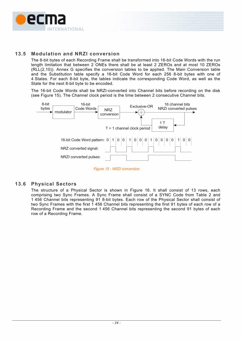
13.5 Modulation and NRZI conversion The 8-bit bytes of each Recording Frame shall be transformed into 16-bit Code Words with the run length limitation that between 2 ONEs there shall be at least 2 ZEROs and at most 10 ZEROs (RLL(2,10)). Annex G specifies the conversion tables to be applied. The Main Conversion table and the Substitution table specify a 16-bit Code Word for each 256 8-bit bytes with one of 4 States. For each 8-bit byte, the tables indicate the corresponding Code Word, as well as the State for the next 8-bit byte to be encoded.
The 16-bit Code Words shall be NRZI-converted into Channel bits before recording on the disk (see Figure 15). The Channel clock period is the time between 2 consecutive Channel bits.
16-bitCode Words
8-bitbytes NRZ
conversionmodulatorExclusive-OR
1 Tdelay
16 channel bitsNRZI converted pulses
T = 1 channel clock period
16-bit Code Word pattern: 0 1 0 0 1 0 0 0 1 0 0 0 0 1 0 0
NRZ converted signal:
NRZI converted pulses:
Figure 15 - NRZI conversion
13.6 Physical Sectors
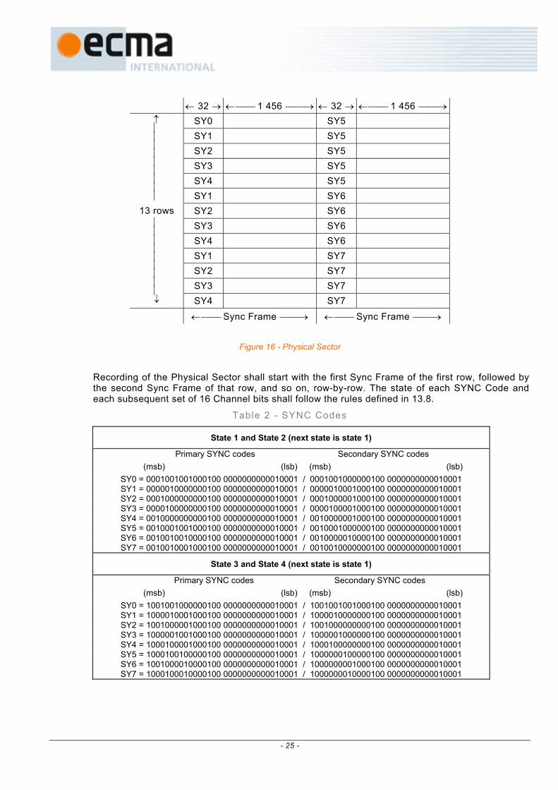
The structure of a Physical Sector is shown in Figure 16. It shall consist of 13 rows, each comprising two Sync Frames. A Sync Frame shall consist of a SYNC Code from Table 2 and 1 456 Channel bits representing 91 8-bit bytes. Each row of the Physical Sector shall consist of two Sync Frames with the first 1 456 Channel bits representing the first 91 bytes of each row of a Recording Frame and the second 1 456 Channel bits representing the second 91 bytes of each row of a Recording Frame.
- 24 -
← 32 → ← 1 456 → ← 32 → ← 1 456 → SY0 SY5 SY1 SY5 SY2 SY5 SY3 SY5 SY4 SY5 SY1 SY6 SY2 SY6 SY3 SY6 SY4 SY6 SY1 SY7 SY2 SY7 SY3 SY7
↑
13 rows ↓ SY4 SY7 ← Sync Frame → ← Sync Frame →
Figure 16 - Physical Sector
Recording of the Physical Sector shall start with the first Sync Frame of the first row, followed by the second Sync Frame of that row, and so on, row-by-row. The state of each SYNC Code and each subsequent set of 16 Channel bits shall follow the rules defined in 13.8.
Table 2 - SYNC Codes
State 1 and State 2 (next state is state 1)
Primary SYNC codes Secondary SYNC codes (msb) (lsb) (msb) (lsb) SY0 = 0001001001000100 0000000000010001 / 0001001000000100 0000000000010001 SY1 = 0000010000000100 0000000000010001 / 0000010001000100 0000000000010001 SY2 = 0001000000000100 0000000000010001 / 0001000001000100 0000000000010001 SY3 = 0000100000000100 0000000000010001 / 0000100001000100 0000000000010001 SY4 = 0010000000000100 0000000000010001 / 0010000001000100 0000000000010001 SY5 = 0010001001000100 0000000000010001 / 0010001000000100 0000000000010001 SY6 = 0010010010000100 0000000000010001 / 0010000010000100 0000000000010001 SY7 = 0010010001000100 0000000000010001 / 0010010000000100 0000000000010001
State 3 and State 4 (next state is state 1)
Primary SYNC codes Secondary SYNC codes (msb) (lsb) (msb) (lsb) SY0 = 1001001000000100 0000000000010001 / 1001001001000100 0000000000010001 SY1 = 1000010001000100 0000000000010001 / 1000010000000100 0000000000010001 SY2 = 1001000001000100 0000000000010001 / 1001000000000100 0000000000010001 SY3 = 1000001001000100 0000000000010001 / 1000001000000100 0000000000010001 SY4 = 1000100001000100 0000000000010001 / 1000100000000100 0000000000010001 SY5 = 1000100100000100 0000000000010001 / 1000000100000100 0000000000010001 SY6 = 1001000010000100 0000000000010001 / 1000000001000100 0000000000010001 SY7 = 1000100010000100 0000000000010001 / 1000000010000100 0000000000010001
- 25 -
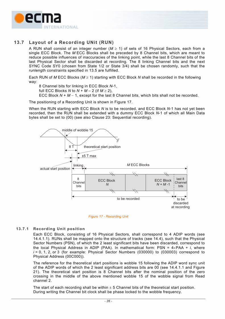
13.7 Layout of a Recording UNit (RUN) A RUN shall consist of an integer number (M ≥ 1) of sets of 16 Physical Sectors, each from a single ECC Block. The M ECC Blocks shall be preceded by 8 Channel bits, which are meant to reduce possible influences of inaccuracies of the linking point, while the last 8 Channel bits of the last Physical Sector shall be discarded at recording. The 8 linking Channel bits and the next SYNC Code SY0 (chosen from State 1/2 or State 3/4) shall be chosen randomly, such that the runlength constraints specified in 13.5 are fulfilled.
Each RUN of M ECC Blocks (M ≥ 1) starting with ECC Block N shall be recorded in the following way: 8 Channel bits for linking in ECC Block N-1, full ECC Blocks N to N + M – 2 (if M ≥ 2), ECC Block N + M − 1, except for the last 8 Channel bits, which bits shall not be recorded.
The positioning of a Recording Unit is shown in Figure 17.
When the RUN starting with ECC Block N is to be recorded, and ECC Block N-1 has not yet been recorded, then the RUN shall be extended with a dummy ECC Block N-1 of which all Main Data bytes shall be set to (00) (see also Clause 23: Sequential recording).
8 T
±5 T max
theoretical start position
actual start position
middle of wobble 15
8 Channel bits
ECC Block N
ECC Block + -1N M
last 8Channel bits
M ECC Blocks
to be discarded at recording
to be recorded
linking
Figure 17 - Recording Unit
13.7.1 Recording Unit posit ion
Each ECC Block, consisting of 16 Physical Sectors, shall correspond to 4 ADIP words (see 14.4.1.1). RUNs shall be mapped onto the structure of tracks (see 14.4), such that the Physical Sector Numbers (PSN), of which the 2 least significant bits have been discarded, correspond to the local Physical Address in ADIP (PAA). In mathematical form: PSN = 4×PAA + i, where i = 0, 1, 2, or 3 (for example: Physical Sector Numbers (030000) to (030003) correspond to Physical Address (00C000)).
The reference for the theoretical start positions is wobble 15 following the ADIP word sync unit of the ADIP words of which the 2 least significant address bits are 00 (see 14.4.1.1 and Figure 21). The theoretical start position is 8 Channel bits after the nominal position of the zero crossing in the middle of the above mentioned wobble 15 of the wobble signal from Read channel 2.
The start of each recording shall be within ± 5 Channel bits of the theoretical start position. During writing the Channel bit clock shall be phase locked to the wobble frequency.
- 26 -

13.8 d.c. component suppression control To ensure a reliable radial tracking and a reliable detection of the HF signals, the low frequency content of the stream of Channel bit patterns should be kept as low as possible. In order to achieve this, the Digital Sum Value (DSV, see 4.3) shall be kept as close to zero as possible. At the beginning of the modulation, the DSV shall be set to 0.
The different ways of diminishing the current value of the DSV are as follows:
a) Choice of SYNC Codes between Primary or Secondary SYNC Codes.
b) For the 8-bit bytes in the range 0 to 87, the Substitution table offers an alternative 16-bit Code Word for all States.
c) For the 8-bit bytes in the range 88 to 255, when the prescribed State is 1 or 4, then the 16-bit Code Word can be chosen either from State 1 or from State 4, so as to ensure that the RLL requirement is met.
In order to use these possibilities, two data streams, Stream 1 and Stream 2, are generated. Stream 1 shall start with the Primary SYNC Code and Stream 2 with the Secondary SYNC Code of the same category of SYNC Codes. As both streams are modulated individually, they generate a different DSV because of the difference between the bit patterns of the Primary and Secondary SYNC Codes.
In the cases b) and c), there are two possibilities to represent a 8-bit byte. The DSV of each stream is computed up to the 8-bit byte preceding the 8-bit byte for which there is this choice. The stream with the lowest DSV is selected and duplicated to the other stream. Then, one of the representations of the next 8-bit byte is entered into Stream 1 and the other into Stream 2. This operation is repeated each time case b) or c) occurs.
Whilst case b) always occurs at the same pattern position in both streams, case c) may occur in one of the streams and not in the other because, for instance, the next State prescribed by the previous 8-bit byte can be 2 or 3 instead of 1 or 4. In that case the following 3-step procedure shall be applied:
1) Compare the DSVs of both streams.
2) If the DSV of the stream in which case c) occurs is smaller than that of the other stream, then the stream in which case c) has occurred is chosen and duplicated to the other stream. One of the representations of the next 8-bit byte is entered into this stream and the other into the other stream.
3) If the DSV of the stream in which case c) has occurred is larger than that of the other stream, then case c) is ignored and the 8-bit byte is represented according to the prescribed State.
In both cases b) and c), if the DSVs are equal, the decision to choose Stream 1 or Stream 2 is implementation-defined.
The procedure for case a) shall be as follows:
1) At the end of each Sync Frame, whether or not case b) and or case c) have occurred, the accumulated DSVs of both streams are compared. The stream with the lower DSV is selected and duplicated to the other stream. Then the next Primary SYNC Code and the Secondary SYNC Code of the proper category are inserted each in one of the streams.
Optionally the procedure for case a) can be extended in the following way:
2) If the DSV at the end of the resulting Sync Frame is greater than +63 or smaller than -64, then the SYNC Code at the beginning of the Sync Frame is changed from Primary to Secondary or vice versa. If this yields a smaller DSV, the change is permanent, if the DSV is not smaller, the original SYNC Code is retained.
During the DSV computation, the actual values of the DSV may vary between -1 000 and +1 000, thus it is recommended that the count range for the DSV be at least from -1 024 to +1 023.
- 27 -
14 Track format
14.1 Track shape The area in the Information Zone (see 10.7) shall contain tracks formed from a single spiral groove. Each track shall form a 360° turn of a continuous spiral. The shape of each track is determined by the requirements in Section 5. Recordings shall be made in the groove.
The tracks in the Information Zone contain a phase modulated sinusoidal deviation from the nominal centrelines, called wobble, which contains addressing information.
The tracks shall be continuous in the Information Zone. The groove tracks shall start at a radius of 22,0 mm max, and end at a radius of 58,75 mm min (see also Annex A).
14.2 Track path The track path shall be a continuous spiral from the inside (beginning of the Lead-in Zone) to the outside (end of the Lead-out Zone) when the disk rotates counter-clockwise as viewed from the optical head.
14.3 Track pitch The track pitch is the distance measured between the average track centrelines of adjacent tracks, measured in the radial direction. The track pitch shall be 0,74 µm ± 0,03 µm. The track pitch averaged over the Information Zone shall be 0,74 µm ± 0,01 µm.
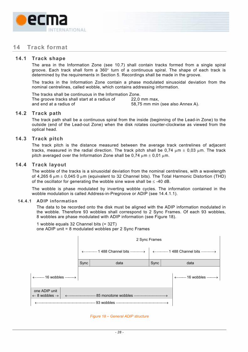
14.4 Track layout The wobble of the tracks is a sinusoidal deviation from the nominal centrelines, with a wavelength of 4,265 6 µm ± 0,045 0 µm (equivalent to 32 Channel bits). The Total Harmonic Distortion (THD) of the oscillator for generating the wobble sine wave shall be ≤ -40 dB.
The wobble is phase modulated by inverting wobble cycles. The information contained in the wobble modulation is called Address-in-Pregroove or ADIP (see 14.4.1.1).
14.4.1 ADIP information The data to be recorded onto the disk must be aligned with the ADIP information modulated in the wobble. Therefore 93 wobbles shall correspond to 2 Sync Frames. Of each 93 wobbles, 8 wobbles are phase modulated with ADIP information (see Figure 18).
1 wobble equals 32 Channel bits (= 32T) one ADIP unit = 8 modulated wobbles per 2 Sync Frames
2 Sync Frames
← 1 488 Channel bits → ← 1 488 Channel bits →
Sync data Sync data
← 16 wobbles → ← 16 wobbles →
one ADIP unit ← 8 wobbles →
← 85 monotone wobbles →
← 93 wobbles →
Figure 18 – General ADIP structure
- 28 -

14.4.1.1 ADIP word structure 52 ADIP units are grouped into one ADIP word each. This means that one ADIP word corresponds to 4 × 13 × 2 Sync Frames ≡ 4 Physical Sectors.
Each ADIP word shall consist of: 1 ADIP sync unit + 51 ADIP data units. ADIP sync unit = 4 inverted wobbles for word sync + 4 monotone wobbles. ADIP data unit = 1 inverted wobble for bit sync + 3 monotone wobbles + 4 wobbles representing one data bit. (see 14.4.1.3)
ADIP word structure:
wobble 0 wobble 1 to 3 wobble 4 to 7
↑ ↑ sync unit word sync ↑ ↑ data unit bit sync data bit 1 ADIP data unit bit sync data bit 2 4 Physical
4 word : : : : Sectors 1 ADIP : : : : ECC words ↓ data unit bit sync data bit 51 ↓ Block
↓ ↓
Figure 19 - ADIP word structure
The information contained in the data bits is as follows:
bit 1: this bit is reserved and shall be set to ZERO.
bits 2 to 23: these 22 bits contain a Physical Address. Data bit 2 is the msb and data bit 23 is the lsb. The addresses increase by one for each next ADIP word. The first address in the Information Zone shall be such that Physical Address (00C000) is located at radius .
Physical Address (098150), which is the first address corresponding to the Lead-out Zone, shall be located at a radius ≤ 58,0 mm (see also Annex A).
mm24,0 0,00,2
+−
bits 24 to 31: these 8 bits contain auxiliary information about the disk.
In the Data Zone and the Lead-out Zone / Outer Drive Area of the disk the auxiliary bytes shall be set to (00).
In the Lead-in Zone and the Inner Drive Area of the disk the auxiliary bytes shall be used as follows: Bit 24 to 31 from 256 consecutive ADIP words, shall form one ADIP Aux Frame with 256 bytes of information. The first byte of each ADIP Aux Frame shall be located in an ADIP word with a Physical Address that is a multiple of 256 (Physical Address = (xxxx00)).
The contents of the 256 bytes are defined in Table 3 and 14.4.2.
bits 32 to 51: these 20 bits contain error correction parities for the ADIP information (see 14.4.1.2).
- 29 -

14.4.1.2 ADIP error correction For the ADIP error correction the ADIP data bits are grouped into 4-bit nibbles. The mapping of the data bits into the nibble array is defined in Figure 20. Bit 0 is a dummy bit, which shall be considered as set to ZERO for the error corrector.
nibble N0 bit 0 bit 1 bit 2 bit 3 ↑
nibble N1 bit 4 bit 5 : : 6 ADIP
: : : : : nibbles address
: bit 20 : : bit 23 ↓
: bit 24 ↑ 2 AUX
nibble N7 bit 28 : bit 31 ↓ nibbles data
nibble N8 bit 32 : : : ↑ nibble
: : : : : 5 based
: : : : : nibbles R-S
nibble N12 bit 48 bit 49 bit 50 bit 51 ↓ ECC
Figure 20 - ADIP error correction structure
A nibble-based RS(13,8,6) code is constructed, of which the 5 parity nibbles N8 to N12, are defined by the remainder polynomial R(x):
)(Gmod)I(N)R( PA512
12
8xxxxx -i
ii == ∑
=
where
and G -i
ii xx 7
7
0N)I( ∑
== ∏ α+=
4
0PA )()(
=k
kxx
α is the primitive root 0010 of the primitive polynomial P(x) = x 4 + x + 1
All bits of the 5 parity nibbles N8 to N12 shall be inverted before recording.
14.4.1.3 ADIP modulation rules The ADIP units are modulated by inverting some of the 8 wobble cycles:
− PW is a positive wobble, which shall start moving towards the inside of the disk.
− NW is a negative wobble, which shall start moving towards the outside of the disk.
− all monotone wobbles shall be PWs.
- 30 -
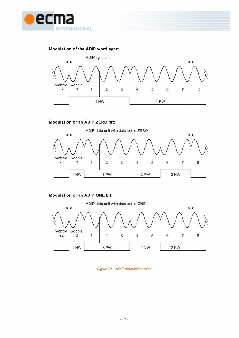
Modulation of the ADIP word sync:
wobble 92
wobble 0 1 2 3 4 5 6 7 8
ADIP sync unit
4 NW 4 PW
Modulation of an ADIP ZERO bit:
wobble 92
wobble 0 1 2 3 4 5 6 7 8
ADIP data unit with data set to ZERO
1 NW 3 PW 2 PW 2 NW
Modulation of an ADIP ONE bit:
wobble 92
wobble 0 1 2 3 4 5 6 7 8
ADIP data unit with data set to ONE
1 NW 3 PW 2 NW 2 PW
Figure 21 - ADIP modulation rules
- 31 -

Table 3 - Physical format informat ion
Byte number Content Number of bytes 0 Disk Category and Version Number 1 1 Disk size 1 2 Disk structure 1 3 Recording density 1
4 to 15 Data Zone allocation 12 16 Set to (00) 1 17 Disk Application Code 1 18 Extended Information indicators 1
19 to 26 Disk Manufacturer ID 8 27 to 29 Media type ID 3
30 Product revision number 1 31 number of Physical format information bytes in use in ADIP up to byte 63 1 32 Primary recording velocity for the basic write strategy 1 33 Upper recording velocity for the basic write strategy 1 34 Wavelength λIND 1 35 normalized Write power dependency on Wavelength (dP/dλ)/(PIND/λIND) 1 36 Maximum read power at Primary velocity 1 37 PIND at Primary velocity 1 38 βtarget at Primary velocity 1 39 Maximum read power at Upper velocity 1 40 PIND at Upper velocity 1 41 βtarget at Upper velocity 1 42 Ttop (≥4) first pulse duration for cm∗ ≥4 at Primary velocity 1 43 Ttop (=3) first pulse duration for cm∗ =3 at Primary velocity 1 44 Tmp multi pulse duration at Primary velocity 1 45 Tlp last pulse duration at Primary velocity 1 46 dTtop (≥4) first pulse lead time for cm∗ ≥4 at Primary velocity 1 47 dTtop (=3) first pulse lead time for cm∗ =3 at Primary velocity 1 48 dTle first pulse leading edge shift for ps∗ =3 at Primary velocity 1 49 Ttop (≥4) first pulse duration for cm∗ ≥4 at Upper velocity 1 50 Ttop (=3) first pulse duration for cm∗ =3 at Upper velocity 1 51 Tmp multi pulse duration at Upper velocity 1 52 Tlp last pulse duration at Upper velocity 1 53 dTtop (≥4) first pulse lead time for cm∗ ≥4 at Upper velocity 1 54 dTtop (=3) first pulse lead time for cm∗ =3 at Upper velocity 1 55 dTle first pulse leading edge shift for ps∗ =3 at Upper velocity 1
56 to 63 Reserved - All (00) 8 64 to 95 Extended Information block 0 32 96 to 127 Extended Information block 1 32
128 to 159 Extended Information block 2 32 160 to 191 Extended Information block 3 32
Annex F)
∗ cm = current mark, ps = previous space (see also
- 32 -

Byte number Content Number of bytes
192 to 223 Extended Information block 4 32 224 to 247 Extended Information block 5 24 248 to 255 Reserved for use in the Control Data Zone – All (00) 8
14.4.2 Physical format information in ADIP This information shall comprise the 256 bytes shown in Table 3. It contains disk information and values for the write strategy parameters to be used with the Optimum Power Control (OPC) algorithm to determine optimum laser power levels for writing (see Annex F and Annex H). The information is copied to the Control Data Zone (see 18.8.1) during finalization of the Lead-in Zone of the disk.
This version of this document specifies several types of disks, with different recording velocity ranges. The specific write parameters for each recording velocity range shall be specified in separate blocks (EI blocks, see 14.4.2.3). The following types of disks (characterized by the so-called X-speed) have now been defined and their ADIP shall contain the EI Blocks as indicated in Table 4.
Table 4 - Types of disks
type of disk
basic write strategy bytes 32 to 63
(1x & 2,4x speed)
4x+ write strategy EI block format 1
(4x speed)
remarks
“2,4x” + − this disk shall be suited for recording speeds of 3,49 & 8,44 m/s only
“4x” + + this disk shall be suited for recording speeds of 3,49 & 8,44 m/s and 13,95 m/s
+ shall be present − shall not be used
14.4.2.1 General information - Bytes 0 to 31 Byte 0 – Disk Category and Version Number Bits b7 to b4 shall specify the Disk Category, they shall be set to 1010, indicating a +R disk.
Bits b3 to b0 shall specify the Version Number, they shall be set to 0001 indicating this Ecma Standard. This Version Number identifies amongst others the definitions of the data in bytes 32 to 63. Drives not acquainted with the specific Version Number of a disk should not try to record on that disk using the information in bytes 32 to 63, which bytes contain the basic write strategy parameters (see Annex N).
Byte 1 – Disk size and maximum transfer rate Bits b7 to b4 shall specify the disk size,
they shall be set to 0000, indicating a 120 mm disk (see also Annex A)
Bits b3 to b0 shall specify the maximum read transfer rate, they shall be set to 1111 indicating no maximum read transfer rate is specified
- 33 -

Byte 2 – Disk structure Bits b7 to b4 shall be set to 0000
Bits b3 to b0 shall specify the type of the recording layer(s): they shall be set to 0010, indicating a write-once recording layer.
Byte 3 – Recording density Bits b7 to b4 shall specify the average Channel bit length in the Information Zone,
they shall be set to 0000, indicating 0,133 µm
Bits b3 to b0 shall specify the average track pitch, they shall be set to 0000, indicating an average track pitch of 0,74 µm
Bytes 4 to 15 – Data Zone allocation Byte 4 shall be set to (00).
Bytes 5 to 7 shall be set to (030000) to specify PSN 196 608 of the first Physical Sector of the Data Zone
Byte 8 shall be set to (00).
Bytes 9 to 11 shall be set to (26053F) to specify PSN 2 491 711 as the last possible Physical Sector of the Data Zone (see also Annex A).
Bytes 12 to 15 shall be set to (00)
Byte 16 – (00) This byte shall be set to (00).
Byte 17 – Disk Application Code This byte can identify disks that are restricted to be used for special applications only. Drives not able to identify the particular application related to a specific Disk Application Code or not able to act according to the rules as defined for this particular application are not allowed to write on a disk with such a code.
(00) identifies a disk for General Purpose use (no restrictions, all drives are allowed to write on a disk carrying this code),
all other codes are reserved.
Byte 18 – Extended Information indicators Bits b7 to b6 are reserved and shall be set to 00
Bits b5 to b0 each of these bits shall indicate the presence of an Extended Information block. Bit bi shall be set to 1 if Extended Information block i, consisting of bytes (64 + i×32) to (95 + i×32), is in use. Else bit bi shall be set to 0.
Bytes 19 to 26 – Disk Manufacturer ID These 8 bytes shall identify the manufacturer of the disk. This name shall be represented by characters from the G0 set + SPACE according to ECMA-43. Trailing bytes not used shall be set to (00).
If the Disk Manufacturer ID is not used, these 8 bytes shall be set to (00)
- 34 -

Bytes 27 to 29 – Media type ID Disk manufacturers can have different types of media, which shall be specified by these 3 bytes. The specific type of disk is denoted in this field by characters from the G0 set + SPACE according to ECMA-43. Trailing bytes not used shall be set to (00).
If the Media type ID is not used these 3 bytes shall be set to (00) NOTE Disks with different characteristics shall be identified by different and unique combinations of Disk Manufacturer ID / Media type ID. Therefore the contents of bytes 19 to 29 shall be approved by the licensors of the +R system.
Byte 30 – Product revision number This byte shall identify the product revision number in binary notation. All disks with the same Disk Manufacturer ID and the same Media type ID, regardless of Product revision numbers, must have the same recording properties (only minor differences are allowed: Product revision numbers shall be irrelevant for recorders). The content of this byte can be chosen freely by the disk manufacturer.
If not used this byte shall be set to (00)
Byte 31 – number of Physical format information bytes in use in ADIP up to byte 63 This byte forms one 8-bit binary number indicating the number of bytes actually in use for the basic Physical format information (in bytes 0 to 63). It shall be set to (38) indicating that only the first 56 bytes of the Physical format information are used.
14.4.2.2 Basic write strategy parameters - Bytes 32 to 63 Byte 32 – Primary recording velocity for the basic write strategy This byte indicates the lowest recording velocity of the disk for the parameters as defined in bytes 34 to 63 in this Physical format information. This recording velocity is equal to the Reference velocity and shall be specified as a number n such that
n = 10 × vPrimary,basic (n rounded off to an integral value)
It shall be set to (23) indicating a Primary writing speed of 3,49 m/s.
Byte 33 – Upper recording velocity for the basic write strategy This byte indicates the highest recording velocity of the disk for the parameters as defined in bytes 34 to 63 in this Physical format information. This recording velocity shall be specified as a number n such that
n = 10 × vUpper,basic (n rounded off to an integral value)
It shall be set to (54) indicating a Upper writing speed of 8,44 m/s.
Byte 34 – Wavelength λIND This byte shall specify the laser wavelength in nanometers at which the optimum write parameters in the following bytes are specified, as a number n such that
n = Wavelength – 600
For this version of the +R system, n shall be equal to (37) indicating that λIND is 655 nanometers.
Byte 35 – Normalized Write power dependency on Wavelength This byte shall specify the average write power dependency on the wavelength normalized by the ratio of PIND and λIND (see 29.3.3 and Annex J), as a number n such that
n = (dP/dλ)/(PIND/λIND)
- 35 -

Byte 36 – Maximum read power, Pr at Primary velocity This byte shall specify the maximum read power Pr in milliwatts at Primary velocity as a number n such that
n = 20 × (Pr – 0,7)
Byte 37 – PIND at Primary velocity PIND is the starting value for the determination of Pwo used in the OPC algorithm, see Annex H and Annex J.
This byte shall specify the indicative value PIND of Pwo in milliwatts at Primary velocity and λIND as a number n such that
n = 20 × (PIND - 5)
Byte 38 – βtarget at Primary velocity
This byte shall specify the target value for β, βtarget at Primary velocity used in the OPC algorithm (see Annex H) as a number n such that
n = 100 × (βtarget + 1)
Byte 39 – Maximum read power, Pr at Upper velocity This byte shall specify the maximum read power Pr in milliwatts at Upper velocity as a number n such that
n = 20 × (Pr – 0,7)
Byte 40 – PIND at Upper velocity PIND is the starting value for the determination of Pwo used in the OPC algorithm, see Annex H and Annex J.
This byte shall specify the indicative value PIND of Pwo in milliwatts at Upper velocity and λIND as a number n such that
n = 20 × (PIND - 5)
Byte 41 – βtarget at Upper velocity
This byte shall specify the target value for β, βtarget at Upper velocity used in the OPC algorithm (see Annex H) as a number n such that
n = 100 × (βtarget + 1)
Byte 42 – Ttop (≥4) first pulse duration for current mark ≥4 at Primary velocity This byte shall specify the duration of the first pulse of the multi pulse train when the current mark is a 4T or greater mark for recording at Primary velocity (see Annex F.1). The value is expressed in fractions of the Channel bit clock period as a number n such that
n = 16 × W
topT
T and 4 ≤ n ≤ 40
Byte 43 – Ttop (=3) first pulse duration for current mark =3 at Primary velocity This byte shall specify the duration of the first pulse of the multi pulse train when the current mark is a 3T mark for recording at Primary velocity (see Annex F.1). The value is expressed in fractions of the Channel bit clock period as a number n such that
n = 16 × W
topT
T and 4 ≤ n ≤ 40
- 36 -

Byte 44 – Tmp multi pulse duration at Primary velocity This byte shall specify the duration of the 2nd pulse through the 2nd to last pulse of the multi pulse train for recording at Primary velocity (see Annex F.1). The value is expressed in fractions of the Channel bit clock period as a number n such that
n = 16 × W
mpT
T and 4 ≤ n ≤ 14
Byte 45 – Tlp last pulse duration at Primary velocity This byte shall specify the duration of the last pulse of the multi pulse train when the current mark is a 4T or greater mark for recording at Primary velocity (see Annex F.1). The value is expressed in fractions of the Channel bit clock period as a number n such that
n = 16 × W
lpT
T and 4 ≤ n ≤ 24
Byte 46 – dTtop (≥4) first pulse lead time for current mark ≥4 at Primary velocity When the current mark is a 4T or greater mark, this byte shall specify the lead time of the first pulse of the multi pulse train relative to the trailing edge of the second Channel bit of the data pulse, for recording at Primary velocity (see Annex F.1). The value is expressed in fractions of the Channel bit clock period as a number n such that
n = 16 × W
topT
dT and 0 ≤ n ≤ 24
Byte 47 – dTtop (=3) first pulse lead time for current mark =3 at Primary velocity When the current mark is a 3T mark, this byte shall specify the lead time of the first pulse of the multi pulse train relative to the trailing edge of the second Channel bit of the data pulse, for recording at Primary velocity (see Annex F.1). The value is expressed in fractions of the Channel bit clock period as a number n such that
n = 16 × W
topT
dT and 0 ≤ n ≤ 24
Byte 48 – dTle first pulse leading edge shift for previous space =3 at Primary velocity This byte shall specify the leading edge correction for the 1st pulse of the multi pulse train when the previous space was a 3T space for recording at Primary velocity (see Annex F.1). The value is expressed in fractions of the Channel bit clock period as a number n such that
n = 16 × W
leT
dT and 0 ≤ n ≤ 4
Byte 49 – Ttop (≥4) first pulse duration for current mark ≥4 at Upper velocity This byte shall specify the duration of the first pulse of the multi pulse train when the current mark is a 4T or greater mark for recording at Upper velocity (see Annex F.1). The value is expressed in fractions of the Channel bit clock period as a number n such that
n = 16 × W
topT
T and 4 ≤ n ≤ 40
Byte 50 – Ttop (3) first pulse duration for current mark =3 at Upper velocity This byte shall specify the duration of the first pulse of the multi pulse train when the current mark is a 3T mark for recording at Upper velocity (see Annex F.1). The value is expressed in fractions of the Channel bit clock period as a number n such that
n = 16 × W
topT
T and 4 ≤ n ≤ 40
- 37 -

Byte 51 – Tmp multi pulse duration at Upper velocity This byte shall specify the duration of the 2nd pulse through the 2nd to last pulse of the multi pulse train for recording at Upper velocity (see Annex F.1). The value is expressed in fractions of the Channel bit clock period as a number n such that
n = 16 × W
mpT
T and 4 ≤ n ≤ 14
Byte 52 – Tlp last pulse duration at Upper velocity This byte shall specify the duration of the last pulse of the multi pulse train when the current mark is a 4T or greater mark for recording at Upper velocity (see Annex F.1). The value is expressed in fractions of the Channel bit clock period as a number n such that
n = 16 × W
lpT
T and 4 ≤ n ≤ 24
Byte 53 – dTtop (≥4) first pulse lead time for current mark ≥4 at Upper velocity When the current mark is a 4T or greater mark, this byte shall specify the lead time of the first pulse of the multi pulse train relative to the trailing edge of the second Channel bit of the data pulse, for recording at Upper velocity (see Annex F.1). The value is expressed in fractions of the Channel bit clock period as a number n such that
n = 16 × W
topT
dT and 0 ≤ n ≤ 24
Byte 54 – dTtop (=3) first pulse lead time for current mark =3 at Upper velocity When the current mark is a 3T mark, this byte shall specify the lead time of the first pulse of the multi pulse train relative to the trailing edge of the second Channel bit of the data pulse, for recording at Upper velocity (see Annex F.1). The value is expressed in fractions of the Channel bit clock period as a number n such that
n = 16 × W
topT
dT and 0 ≤ n ≤ 24
Byte 55 – dTle first pulse leading edge shift for previous space =3 at Upper velocity This byte shall specify the leading edge correction for the 1st pulse of the multi pulse train when the previous space was a 3T space for recording at Upper velocity (see Annex F.1). The value is expressed in fractions of the Channel bit clock period as a number n such that
n = 16 × W
leT
dT and 0 ≤ n ≤ 4
Bytes 56 to 63 – Reserved - All (00) These bytes shall be set to all (00).
14.4.2.3 Extended Information blocks - Bytes (64 + i×32) to (95 + i×32) (i = 0 to 5)
Extended Information (EI) blocks are meant to facilitate future extensions. Each such block consists of 32 bytes. These bytes can hold for instance parameters for alternative write strategies or other advanced parameters. The presence of an Extended Information block shall be indicated by the appropriate bit in byte 18. If an Extended Information block is not used, all 32 bytes shall be set to (00).
Byte (64 + i×32) Extended Information block i format number
indicates the format number which identifies the definitions of the data in bytes (65 + i×32) to (95 + i×32).
- 38 -

A disk can have several Extended Information blocks. The contents of blocks with different format numbers have to be interpreted each according to their respective definitions. The contents of blocks with the same format number are interpreted in the same way; the parameters specified in these blocks can have different values. Drives not acquainted with the specific format number in block i, should not use the parameters in this Extended Information block (see Annex N).
If the format number is set to 255, the related Extended Information block is not an independent block but a continuation of the preceding Extended Information block (to be used if 32 bytes are not sufficient for a set of parameters). NOTE The contents of an EI block are identified by the format number of the block only. The position of the EI block in the ADIP Aux Frame is irrelevant for this, so an EI block with format number n could be allocated at any position i. Therefore drives should always check the format numbers in the EI blocks to be sure that the write strategies are correctly interpreted.
Bytes (65 + i×32) to (95 + i×32) Each parameter set defined for these bytes shall be identified by a unique format number.
Bytes 248 to 255 – Reserved for use in the Control Data Zone - All (00) These bytes can not be copied to the Control Data Zone and shall therefore not be used and be set to (00).
14.4.2.3.1 Extended information for the “4x+” write strategy This Extended Information block specifies the parameters for a write strategy usable at speeds of 4 times the basic DVD speed (4×3,49 m/s) or higher. The write strategy used at these speeds is a so-called “Blocked” write strategy as defined in Annex F.2. If the disk can not be recorded under these “4x+” conditions, this EI block shall not be used (all bytes set to (00)).
Byte 18 – Extended Information indicators This byte shall be set to xxxx xxx1 indicating Extended Information block 0 is in use.
Table 5 - Extended Informat ion block 0
Byte number Content Number of bytes
64 Format number 1 65 Reserved - set to (00) 1 66 Primary recording velocity for the parameter set in this EI block 1 67 Upper recording velocity for the parameter set in this EI block 1 68 Maximum read power at Primary velocity 1 69 PIND at Primary velocity 1 70 βtarget at Primary velocity 1 71 dPw (=3) power enhancement for cm =3 at Primary velocity 1 72 dPw (=4) power enhancement for cm =4 at Primary velocity 1 73 Ttop (≥4) first part of write pulse for cm ≥4 at Primary velocity
(= dTtop (≥4) + TW) 1
74 Ttop (=3) write pulse duration for cm =3 at Primary velocity 1 75 Tmp at Primary velocity (= TW) 1 76 Tlp last part of write pulse for cm ≥4 at Primary velocity 1 77 dTtop (≥4) write pulse lead time for cm ≥4 at Primary velocity 1 78 dTtop (=3) write pulse lead time for cm =3 at Primary velocity 1 79 dTle write pulse leading edge correction for ps =3 at Primary velocity 1 80 Reserved - set to (00) 1
- 39 -

Byte number Content Number of bytes
81 Reserved - set to (00) 1 82 Maximum read power at Upper velocity 1 83 PIND at Upper velocity 1 84 βtarget at Upper velocity 1 85 dPw (=3) power enhancement for cm =3 at Upper velocity 1 86 dPw (=4) power enhancement for cm =4 at Upper velocity 1 87 Ttop (≥4) first part of write pulse for cm ≥4 at Upper velocity
(= dTtop (≥4) + TW) 1
88 Ttop (=3) write pulse duration for cm =3 at Upper velocity 1 89 Tmp at Upper velocity (= TW) 1 90 Tlp last part of write pulse for cm ≥4 at Upper velocity 1 91 dTtop (≥4) write pulse lead time for cm ≥4 at Upper velocity 1 92 dTtop (=3) write pulse lead time for cm =3 at Upper velocity 1 93 dTle write pulse leading edge correction for ps =3 at Upper velocity 1 94 Reserved - set to (00) 1 95 Reserved - set to (00) 1
Byte 64 – Extended Information block 0 format number This byte shall be set to 0000 0001 indicating format 1, for which bytes 65 to 95 have the following meaning:
Byte 65 – Reserved This byte is reserved and shall be set to (00)
Byte 66 – Primary recording velocity for the parameter set in this EI block This byte indicates the lowest recording velocity of the disk for the parameters as defined in this EI block. This recording velocity shall be specified as a number n such that
n = 4 × vPrimary,EI 0 (n rounded off to an integral value)
It shall be set to (38) indicating a Primary writing speed of 14 m/s.
Byte 67 – Upper recording velocity for the parameter set in this EI block This byte indicates the highest recording velocity of the disk for the parameters as defined in this EI block. This recording velocity shall be specified as a number n such that
n = 4 × vUpper,EI 0 (n rounded off to an integral value)
It shall be set to (38) indicating an Upper writing speed of 14 m/s. (In future when higher recording speeds which are compatible with this write strategy become possible, higher values can be allowed.)
Byte 68 – Maximum read power, Pr at Primary velocity This byte shall specify the maximum read power Pr in milliwatts at Primary velocity as a number n such that
n = 20 × (Pr – 0,7)
Byte 69 – PIND at Primary velocity PIND is the starting value for the determination of Pwo used in the OPC algorithm, see Annex H and Annex J.
- 40 -

This byte shall specify the indicative value PIND of Pwo in milliwatts at Primary velocity and λIND as a number n such that
n = 5 × (PIND - 5)
Byte 70 – βtarget at Primary velocity
This byte shall specify the target value for β, βtarget at Primary velocity used in the OPC algorithm (see Annex H) as a number n such that
n = 100 × (βtarget + 1)
Byte 71 – dPw (=3) power enhancement for current mark =3 at Primary velocity This byte shall specify the additional power for writing the 3T marks (see Annex F.2) at Primary velocity as a number n such that
n = 200 × dPw / Pwo and 0 ≤ n ≤ 100
Byte 72 – dPw (=4) power enhancement for current mark =4 at Primary velocity This byte shall specify the additional power for writing the 4T marks (see Annex F.2) at Primary velocity as a number n such that
n = 200 × dPw / Pwo and 0 ≤ n ≤ 100
Byte 73 – Ttop (≥4) first part of write pulse for current mark ≥4 at Primary velocity This byte shall specify the duration of the first part of the write pulse when the current mark is a 4T or greater mark for recording at Primary velocity (see Annex F.2). The value is expressed in fractions of the Channel bit clock period as a number n such that
n = 16 × W
topT
T and n = value of byte 77 + 16
Byte 74 – Ttop (=3) write pulse duration for current mark =3 at Primary velocity This byte shall specify the duration of the write pulse when the current mark is a 3T mark for recording at Primary velocity (see Annex F.2). The value is expressed in fractions of the Channel bit clock period as a number n such that
n = 16 × W
topT
T and 4 ≤ n ≤ 48
Byte 75 – Tmp at Primary velocity
This byte has been added for consistency with the basic description of the write strategy (see Annex F). The value is expressed in fractions of the Channel bit clock period as a number n such that
n = 16 × W
mpT
T and n = 16
Byte 76 – Tlp last part of write pulse at Primary velocity
This byte shall specify the duration of the last part of the write pulse when the current mark is a 4T or greater mark for recording at Primary velocity (see Annex F.2). The value is expressed in fractions of the Channel bit clock period as a number n such that
n = 16 × W
lpT
T and 0 ≤ n ≤ 16
- 41 -

Byte 77 – dTtop (≥4) write pulse lead time for current mark ≥4 at Primary velocity
When the current mark is a 4T or greater mark, this byte shall specify the lead time of the write pulse relative to the trailing edge of the second Channel bit of the data pulse, for recording at Primary velocity (see Annex F.2). The value is expressed in fractions of the Channel bit clock period as a number n such that
n = 16 × W
topT
dT and 0 ≤ n ≤ 32
Byte 78 – dTtop (=3) write pulse lead time for current mark =3 at Primary velocity
When the current mark is a 3T mark, this byte shall specify the lead time of the write pulse relative to the trailing edge of the second Channel bit of the data pulse, for recording at Primary velocity (see Annex F.2). The value is expressed in fractions of the Channel bit clock period as a number n such that
n = 16 × W
topT
dT and 0 ≤ n ≤ 32
Byte 79 – dTle write pulse leading edge correction for previous space =3 at Primary velocity
This byte shall specify the leading edge correction for the write pulse when the previous space was a 3T space for recording at Primary velocity (see Annex F.2). The value is expressed in fractions of the Channel bit clock period as a number n such that
n = 16 × W
leT
dT and 0 ≤ n ≤ 4
Bytes 80 to 81 – Reserved - All (00) These bytes shall be set to all (00).
Byte 82 – Maximum read power, Pr at Upper velocity This byte shall specify the maximum read power Pr in milliwatts at Upper velocity as a number n such that
n = 20 × (Pr – 0,7)
Byte 83 – PIND at Upper velocity PIND is the starting value for the determination of Pwo used in the OPC algorithm, see Annex H and Annex J.
This byte shall specify the indicative value PIND of Pwo in milliwatts at Upper velocity and λIND as a number n such that
n = 5 × (PIND - 5)
Byte 84 – βtarget at Upper velocity
This byte shall specify the target value for β, βtarget at Upper velocity used in the OPC algorithm (see Annex H) as a number n such that
n = 100 × (βtarget + 1)
Byte 85 – dPw (=3) power enhancement for current mark =3 at Upper velocity This byte shall specify the additional power for writing the 3T marks (see Annex F.2) at Upper velocity as a number n such that
n = 200 × dPw / Pwo and 0 ≤ n ≤ 100
- 42 -

Byte 86 – dPw (=4) power enhancement for current mark =4 at Upper velocity This byte shall specify the additional power for writing the 4T marks (see Annex F.2) at Upper velocity as a number n such that
n = 200 × dPw / Pwo and 0 ≤ n ≤ 100
Byte 87 – Ttop (≥4) first part of write pulse for current mark ≥4 at Upper velocity This byte shall specify the duration of the first part of the write pulse when the current mark is a 4T or greater mark for recording at Upper velocity (see Annex F.2). The value is expressed in fractions of the Channel bit clock period as a number n such that
n = 16 × W
topT
T and n = value of byte 91 + 16
Byte 88 – Ttop (=3) write pulse duration for current mark =3 at Upper velocity This byte shall specify the duration of the write pulse when the current mark is a 3T mark for recording at Upper velocity (see Annex F.2). The value is expressed in fractions of the Channel bit clock period as a number n such that
n = 16 × W
topT
T and 4 ≤ n ≤ 48
Byte 89 – Tmp at Upper velocity
This byte has been added for consistency with the basic description of the write strategy (see Annex F). The value is expressed in fractions of the Channel bit clock period as a number n such that
n = 16 × W
mpT
T and n = 16
Byte 90 – Tlp last part of write pulse at Upper velocity
This byte shall specify the duration of the last part of the write pulse when the current mark is a 4T or greater mark for recording at Upper velocity (see Annex F.2). The value is expressed in fractions of the Channel bit clock period as a number n such that
n = 16 × W
lpT
T and 0 ≤ n ≤ 16
Byte 91 – dTtop (≥4) write pulse lead time for current mark ≥4 at Upper velocity
When the current mark is a 4T or greater mark, this byte shall specify the lead time of the write pulse relative to the trailing edge of the second Channel bit of the data pulse, for recording at Upper velocity (see Annex F.2). The value is expressed in fractions of the Channel bit clock period as a number n such that
n = 16 × W
topT
dT and 0 ≤ n ≤ 32
Byte 92 – dTtop (=3) write pulse lead time for current mark =3 at Upper velocity
When the current mark is a 3T mark, this byte shall specify the lead time of the write pulse relative to the trailing edge of the second Channel bit of the data pulse, for recording at Upper velocity (see Annex F.2). The value is expressed in fractions of the Channel bit clock period as a number n such that
n = 16 × W
topT
dT and 0 ≤ n ≤ 32
- 43 -

Byte 93 – dTle write pulse leading edge correction for previous space =3 at Upper velocity
This byte shall specify the leading edge correction for the write pulse when the previous space was a 3T space for recording at Upper velocity (see Annex F.2). The value is expressed in fractions of the Channel bit clock period as a number n such that
n = 16 × W
leT
dT and 0 ≤ n ≤ 4
Bytes 94 to 95 – Reserved - All (00) These bytes shall be set to all (00).
- 44 -

Section 4 - Format of the Information Zone
15 General description of the Information Zone The Information Zone shall contain all information on the disk relevant for data interchange. The Information Zone may contain one or more sessions (see Clause 22). In double-sided disks there is one Information Zone per side. The Data Zones are intended for the recording of User Data.
The Lead-in Zone contains control information. The Lead-out Zone allows for a continuous smooth lead-out and also contains control information.
The Inner and Outer Drive Areas are meant for disk testing.
In the next Clauses 16 to 21 a description is given for a Single-session disk. In such a disk, the Lead-in Zone, the Data Zone and the Lead-out Zone constitute the recordable area in which the information is recorded using a non-reversible effect. The layout of a Multi-session disk is defined in Clause 22.
16 Layout of the Information Zone of a Single-session disk The Information Zone of single-sided and of each side of double-sided disks shall be sub-divided as shown in Table 6. The radii indicated in Table 6 for some of the Zones are the nominal values of the centre of the first (or last) track of the Zone.
16.1 Physical Sector Numbers (PSNs) The first Physical Sector of the Data Zone shall have PSN (030000). The PSNs increase by 1 for each next Physical Sector in the whole Information Zone (Figure 22).
Radius(02FFFF) (030000)
PhysicalSector
Number
InnerDriveArea
OuterDriveArea
Lead-inZone
Lead-outZone
Information Zone
Address
Data Zone
Figure 22 - Physical Sector numbering
NOTE The Physical Sector Number of the first Physical Sector of the Data Zone is large enough so as to prevent a Physical Sector Number ≤ 0 to occur anywhere on the disk.
- 45 -
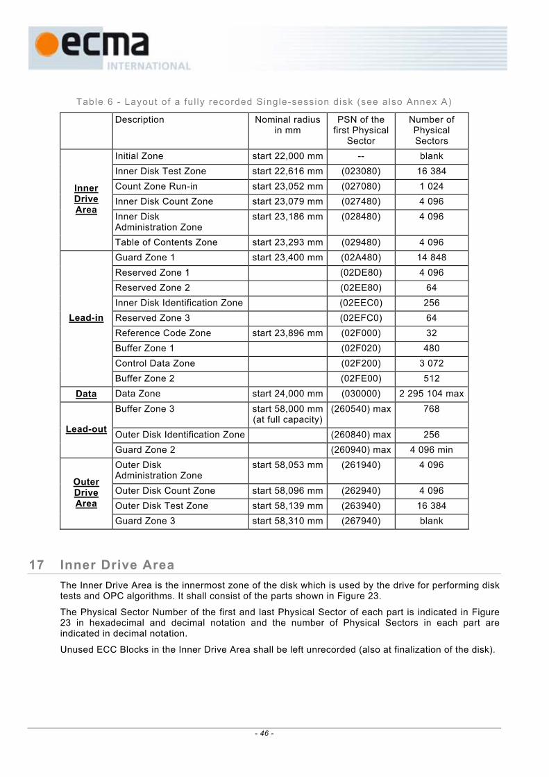
Table 6 - Layout of a ful ly recorded Single-session disk (see also Annex A)
Description Nominal radius in mm
PSN of the first Physical
Sector
Number of Physical Sectors
Initial Zone start 22,000 mm -- blank Inner Disk Test Zone start 22,616 mm (023080) 16 384 Count Zone Run-in start 23,052 mm (027080) 1 024 Inner Disk Count Zone start 23,079 mm (027480) 4 096 Inner Disk Administration Zone
start 23,186 mm (028480) 4 096
Inner Drive Area
Table of Contents Zone start 23,293 mm (029480) 4 096 Guard Zone 1 start 23,400 mm (02A480) 14 848 Reserved Zone 1 (02DE80) 4 096 Reserved Zone 2 (02EE80) 64 Inner Disk Identification Zone (02EEC0) 256 Reserved Zone 3 (02EFC0) 64 Reference Code Zone start 23,896 mm (02F000) 32 Buffer Zone 1 (02F020) 480 Control Data Zone (02F200) 3 072
Lead-in
Buffer Zone 2 (02FE00) 512 Data Data Zone start 24,000 mm (030000) 2 295 104 max
Buffer Zone 3 start 58,000 mm(at full capacity)
(260540) max 768
Outer Disk Identification Zone (260840) max 256 Lead-out
Guard Zone 2 (260940) max 4 096 min Outer Disk Administration Zone
start 58,053 mm (261940) 4 096
Outer Disk Count Zone start 58,096 mm (262940) 4 096 Outer Disk Test Zone start 58,139 mm (263940) 16 384
Outer Drive Area
Guard Zone 3 start 58,310 mm (267940) blank
17 Inner Drive Area The Inner Drive Area is the innermost zone of the disk which is used by the drive for performing disk tests and OPC algorithms. It shall consist of the parts shown in Figure 23.
The Physical Sector Number of the first and last Physical Sector of each part is indicated in Figure 23 in hexadecimal and decimal notation and the number of Physical Sectors in each part are indicated in decimal notation.
Unused ECC Blocks in the Inner Drive Area shall be left unrecorded (also at finalization of the disk).
- 46 -

Initial Zone
Physical Sector 143 488
Physical Sector 159 871
Inner Disk Test Zone 16 384 Physical Sectors
Physical Sector (023080) Physical Sector (02707F)
Physical Sector 159 872
Physical Sector 160 895
Count Zone Run-in 1 024 Physical Sectors
Physical Sector (027080) Physical Sector (02747F)
Physical Sector 160 896
Physical Sector 164 991
Inner Disk Count Zone 4 096 Physical Sectors
Physical Sector (027480) Physical Sector (02847F)
Physical Sector 164 992
Physical Sector 169 087
Inner Disk Administration Zone 4 096 Physical Sectors
Physical Sector (028480) Physical Sector (02947F)
Physical Sector 169 088
Physical Sector 173 183
Table of Contents Zone 4 096 Physical Sectors
Physical Sector (029480) Physical Sector (02A47F)
Lead-in Zone
Figure 23 – Inner Drive Area
17.1 Initial Zone This Zone shall remain blank.
17.2 Inner Disk Test Zone 16 384 Physical Sectors reserved for drive testing and OPC algorithms (see Annex H). The order in which these Physical Sectors shall be used is from the outer side of the disk towards the inner side of the disk, so from the highest address towards the lowest address.
17.3 Count Zone Run-in This area with the size of 1 024 Physical Sectors is meant as a Run-in area for the Inner Disk Count Zone and shall be left unrecorded.
17.4 Inner Disk Count Zone 4 096 Physical Sectors reserved for counting the number of OPC algorithms performed in the Inner Disk Test Zone (see Annex H).
Whenever an ECC Block or part of it in the Inner Disk Test Zone has been recorded, the ECC Block shall be flagged by recording 4 Physical Sectors in the Inner Disk Count Zone. These 4 Physical Sectors shall be formatted according to the rules specified in 13.1 and the underlying subclauses, 13.2, 13.4, 13.5 and 13.6, whereby the Main Data bytes and the PI and PO bytes (see 13.3) can be chosen freely.
The relation between the first Physical Sector number PSNIDT of the used ECC Block in the Inner Disk Test Zone and the Physical Sector numbers PSNIDC to PSNIDC + 3 of the 4 Physical Sectors in the Inner Disk Count Zone is determined by the following mathematical expression:
PSNIDC = {(PSNIDT) – (023080)}/(04) + (027480)
17.5 Inner Disk Administration Zone 4 096 Physical Sectors to be used for optional drive specific information. The first 16 physical sectors of this Zone shall be filled with all Main Data set to (00).
- 47 -

Table 7 – General format of Disk Administrat ion ECC Blocks
Physical Sector of each Adm. Block
Main Data BP Description
0 D0 to D3 Content Descriptor
0 D4 to D7 Reserved and set (00)
0 D8 to D39 Drive ID
0 D40 to D63 Reserved and set (00)
0 D64 to D2 047 Drive Specific
1 to 15 D0 - D2 047 Drive Specific
Physical Sector 0 / bytes D0 to D3 – Content Descriptor these bytes identify the Administration Block and shall be set to (41444D00), representing the characters “ADM” and the version number 0.
Physical Sector 0 / bytes D4 to D7 – Reserved these bytes are reserved and shall be set to (00).
Physical Sector 0 / bytes D8 to D39 – Drive ID these bytes shall contain the drive ID as specified in 25.1, bytes D8 to D39.
Physical Sector 0 / bytes D40 to D63 – Reserved these bytes are reserved and shall be set to (00).
Physical Sector 0 / bytes D64 to D2 047 – Drive Specific these bytes can be used to store Drive Specific information. The format is not defined and can be freely chosen by the drive manufacturer.
Physical Sectors 1 to 15 / bytes D0 to D2 047 – Drive Specific these bytes can be used to store Drive Specific information. The format is not defined and can be freely chosen by the drive manufacturer.
17.6 Table of Contents (TOC) Zone 4 096 Physical Sectors to store information about the locations of Sessions and recordings on the disk. The first 16 physical sectors of this Zone shall be filled with all Main Data set to (00).
This Zone consists of 2 parts:
- part 1: consists of 191 ECC Blocks (TOC Blocks) to be used to store the locations of all Closed Sessions,
- part 2: consists of 1024 Physical Sectors, grouped in units of 4 sectors, where each unit corresponds to one ADIP word. These units shall be used as Recorded Area Indicators.
17.6.1 Table of Contents Blocks Whenever a Session is closed, the next ECC Block in the Table of Contents Zone, immediately following the last TOC Block, shall be recorded with the locations of all Closed Sessions. The first ECC Block in the Table of Contents Zone has to be used as a run-in for the second ECC Block. If all 191 TOC Blocks have been used, no additional Sessions shall be added (see also 23.2 and 23.3).
- 48 -

The format of the TOC Blocks shall be as defined in Table 8:
Table 8 - Format of the TOC Blocks
Physical Sector of TOC block
Main Data byte position
Description number of bytes
0 D0 to D3 Content Descriptor 4 0 D4 to D7 Reserved and set to (00) 4 0 D8 to D39 Drive ID 32 0 D40 to D63 Reserved and set to (00) 24 0 D64 to D79 TOC Item 0 16 0 ... 0 D64+i×16 to D79+i×16 TOC Item i 16 0 ... ... 0 D64+(N-1)×16 to
D79+(N-1)×16 TOC Item N-1 16
0 D64+N×16 to D2 047 Reserved and set to (00) 1 984 - N×16 1 to 3 D0 to D2 047 Extension for TOC Items
or Reserved and set to (00)
3×2 048
4 to 7 D0 to D2 047 Repetition of Sectors 0 to 3 (recommended) or
Reserved and set to (00)
4×2 048
8 to 11 D0 to D2 047 Repetition of Sectors 0 to 3 (recommended) or
Reserved and set to (00)
4×2 048
12 to 15 D0 to D2 047 Repetition of Sectors 0 to 3 (recommended) or
Reserved and set to (00)
4×2 048
Physical Sector 0 / bytes D0 to D3 – Content Descriptor these bytes identify the TOC Block and shall be set to (544F4300), representing the characters “TOC” and the version number 0.
Physical Sector 0 / bytes D4 to D7 – Reserved these bytes are reserved and shall be set to (00).
Physical Sector 0 / bytes D8 to D39 – Drive ID these bytes shall contain the drive ID as specified in 25.1, bytes D8 to D39.
Physical Sector 0 / bytes D40 to D63 – Reserved these bytes are reserved and shall be set to (00).
Physical Sector 0 / bytes D64 to D2 047 – TOC Items these bytes are grouped in units of 16 bytes each. Each unit of 16 bytes can contain a TOC Item according to the following format. All unused bytes shall be set to (00).
Physical Sectors 1 to 3 / bytes D0 to D2 047 – Extension for TOC Items or Reserved these bytes can be used to hold additional TOC Items. All unused bytes shall be set to (00).
- 49 -

Physical Sectors 4 to 15 / bytes D0 to D2 047 – Repetitions of Sectors 0 to 3 or all Reserved For robustness reasons it is recommended to repeat the content of Sectors 0 to 3 in Sectors 4 to 7, in Sectors 8 to 11 and in Sectors 12 to 15.
If this option is not used, these bytes shall be set to (00). It is a matter of drive implementation to recognize and make use of the repetitions.
17.6.1.1 TOC Items:
Item byte position
Description number of bytes
B0 to B2 TOC Item descriptor 3 B3 Session Status 1 B4 Session number 1
B5 to B7 Session start address 3 B8 to B10 Session end address 3 B11 to B12 Last Fragment number in Session 2 B13 to B15 Reserved and set to (00) 3
The TOC Block shall contain a TOC Item for each Closed Session on the disk. The TOC Items shall be ordered with increasing numbers and addresses.
TOC Item bytes B0 to B2 – TOC Item descriptor these 3 bytes identify the item type and shall be set to (544349), representing the characters “TCI”.
TOC Item byte B3 – Session Status this byte shall indicate the Status of the last Session. It shall be set to (00) in all TOC Items, except in the TOC Item describing the last Session on the disk.
If set to (00) in the last TOC Item, adding a new Session to the disk is allowed. If set to (01) in the last TOC Item, the last Session shall be the final Session on the disk. The disk has been finalized and adding new Sessions is not allowed (see 23.3).
TOC Item byte B4 – Session number this byte shall specify the sequence number of the Session specified in this item.
TOC Item bytes B5 to B7 – Session start address these 3 bytes shall specify the PSN of the first Physical Sector in the Data Zone of the Session specified in this item.
TOC Item bytes B8 to B10 – Session end address these 3 bytes shall specify the PSN of the last Physical Sector in the Data Zone of the Session specified in this item.
TOC Item bytes B11 to B12 – Last Fragment number in Session these 2 bytes specify the sequence number of the last Fragment in the Session specified in this item. If this option is not used, these bytes shall be set to (00).
TOC Item bytes B13 to B15 – Reserved these 3 bytes are reserved and shall be set to (00).
- 50 -

17.6.2 Recorded Area Indicators To speed up the access of the disk, the recorder needs to know in which region of the disk the last written ECC Block can be found. For this purpose a kind of “bitmap” is defined, based on recorded areas with the size of 4 Physical Sectors, each area corresponding to one ADIP word. The 4 Physical Sectors shall be formatted according to the rules specified in 13.1 and the underlying subclauses, 13.2, 13.4, 13.5 and 13.6, whereby the Main Data bytes and the PI and PO bytes (see 13.3) can be chosen freely.
1 024 Physical Sectors have been reserved for this “bitmap” purpose, allowing to divide the disk into maximum 256 regions. The Recorded Area Indicators shall be used from the outer side of the TOC Zone towards the inner side of the TOC Zone (see Figure 24). By means of an “HF-detection” the recorder can find the locations of the Recorded Area Indicators and determine the regions which contain recorded ECC Blocks.
Recorded Area Indicators (identified by their PSNs) ←→
TOC Blocks
(02A080)--(02A083)
(02A084)- -(02A087) ---- (02A300)-
-(02A303) (02A304)--(02A307) ---- (02A478)-
-(02A47B) (02A47C)--(02A47F)
Guard Zone 1
←→ Blank
←→ Recorded
Figure 24 – Use of Recorded Area Indicators
Each region of 640 ECC Blocks between PSN = (030000) and PSN = (26053F) corresponds to one Recorded Area Indicator. All regions that contain one or more recorded ECC Blocks shall be indicated by their Recorded Area Indicator. In mathematical form:
if the Recorded Area Indicator composed of the Physical Sectors with PSNRAI to PSNRAI + 3 has been recorded, than the region between: PSN = (02A47C)-(PSNRAI)}×(A00)+(030000) and PSN = {(02A47C)-(PSNRAI)}×(A00)+(0327FF) contains recorded ECC Blocks, or in decimal notation: PSN = {173180-PSNRAI}×2560+196608 and PSN = {173180-PSNRAI}×2560+206847.
Whenever the disk is ejected from the drive, the Recorded Area Indicators shall reflect the actual status of the recordings on the disk.
18 Lead-in Zone The Lead-in Zone is located at the inner side of the Information Zone. It shall consist of the parts shown in Figure 25.
The Physical Sector Number of the first and last Physical Sector of each part is indicated in Figure 25 in hexadecimal and decimal notation and the number of Physical Sectors in each part are indicated in decimal notation.
A maiden disk does not have any data recorded in the Lead-in Zone. After finalization of the disk or closing of the first Session, the Lead-in Zone shall be recorded according to 18.1 to 18.9.
18.1 Guard Zone 1 This Guard Zone is used to create a minimum amount of Lead-in Zone required for compatibility. This zone shall contain 14 848 Physical Sectors, all filled with Main Data set to (00).
18.2 Reserved Zone 1 4 096 Physical Sectors are reserved and shall be set (00).
- 51 -

18.3 Reserved Zone 2 64 Physical Sectors are reserved and shall be set (00).
Inner Drive Area
Physical Sector 173 184
Physical Sector 188 031
Guard Zone 1 14 848 Physical Sectors
with Main Data set to (00)
Physical Sector (02A480) Physical Sector (02DE7F)
Physical Sector 188 032
Physical Sector 192 127
Reserved Zone 1 4 096 Physical Sectors
Physical Sector (02DE80) Physical Sector (02EE7F)
Physical Sector 192 128
Physical Sector 192 191
Reserved Zone 2 64 Physical Sectors
Physical Sector (02EE80) Physical Sector (02EEBF)
Physical Sector 192 192
Physical Sector 192 447
Inner Disk Identification Zone 256 Physical Sectors
Physical Sector (02EEC0) Physical Sector (02EFBF)
Physical Sector 192 448
Physical Sector 192 511
Reserved Zone 3 64 Physical Sectors
Physical Sector (02EFC0) Physical Sector (02EFFF)
Physical Sector 192 512
Physical Sector 192 543
Reference Code Zone 32 Physical Sectors
Physical Sector (02F000) Physical Sector (02F01F)
Physical Sector 192 544
Physical Sector 193 023
Buffer Zone 1 480 Physical Sectors
with Main Data set to (00)
Physical Sector (02F020) Physical Sector (02F1FF)
Physical Sector 193 024
Physical Sector 196 095
Control Data Zone 3 072 Physical Sectors
Physical Sector (02F200) Physical Sector (02FDFF)
Physical Sector 196 096
Physical Sector 196 607
Buffer Zone 2 512 Physical Sectors
with Main Data set to (00)
Physical Sector (02FE00) Physical Sector (02FFFF)
Data Zone
Figure 25 - Lead-in Zone
18.4 Inner Disk Identification Zone 256 Physical Sectors reserved for information agreed upon by the data interchange parties. Each set of 16 Physical Sectors from one ECC Block is either a Disk Control Block (DCB) (see Clause 25) or recorded with all (00) Main Data. Each ECC Block in this Zone following one recorded with all (00) Main Data shall also be recorded with all (00) Main Data.
18.5 Reserved Zone 3 64 Physical Sectors are reserved and shall be set (00).
18.6 Reference Code Zone The recorded Reference Code Zone shall consist of the 32 Physical Sectors from two ECC Blocks which generate a specific Channel bit pattern on the disk. This shall be achieved by setting to (AC) all 2 048 Main Data bytes of each corresponding Data Frame. Moreover, no scrambling shall be applied to these Data Frames, except to the first 160 Main Data bytes of the first Data Frame of each ECC Block.
- 52 -

18.7 Buffer Zone 1 This Zone shall consist of 480 Physical Sectors from 30 ECC Blocks. The Main Data of the Data Frames in this Zone shall be set to all (00).
18.8 Control Data Zone This Zone shall consist of 3 072 Physical Sectors from 192 ECC Blocks. The content of the 16 Physical Sectors of each ECC Block is repeated 192 times. The structure of a Control Data Block shall be as shown in Figure 26.
Physical format information
2 048 bytes
Disk manufacturing information
2 048 bytes
Content provider information
14 × 2 048 bytes
Figure 26 - Structure of a Control Data Block
18.8.1 Physical format information
This information shall comprise the 2 048 bytes shown in Table 9. It contains disk and format information.
Table 9 - Physical format informat ion
Byte number Content Number of bytes
0 Disk Category and Version Number 1 1 Disk size 1 2 Disk structure 1 3 Recording density 1
4 to 15 Data Zone allocation 12 16 Set to (00) 1 17 Disk Application Code 1 18 Extended Information indicators 1
19 to 26 Disk Manufacturer ID 8 27 to 29 Media type ID 3
30 Product revision number 1 31 number of Physical format information bytes in use in ADIP up to byte 63 1 32 Primary recording velocity for the basic write strategy 1 33 Upper recording velocity for the basic write strategy 1 34 Wavelength λIND 1 35 normalized Write power dependency on Wavelength (dP/dλ)/(PIND/λIND) 1 36 Maximum read power at Primary velocity 1
- 53 -
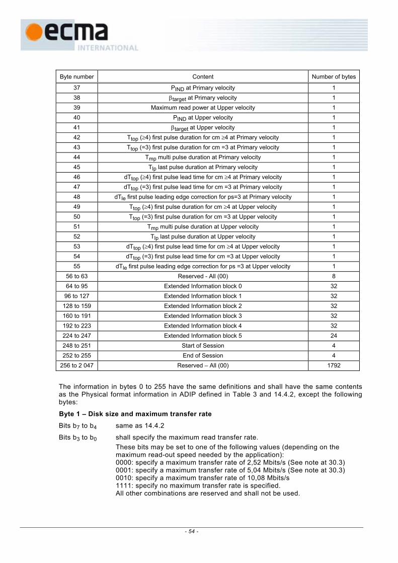
Byte number Content Number of bytes
37 PIND at Primary velocity 1 38 βtarget at Primary velocity 1 39 Maximum read power at Upper velocity 1 40 PIND at Upper velocity 1 41 βtarget at Upper velocity 1 42 Ttop (≥4) first pulse duration for cm ≥4 at Primary velocity 1 43 Ttop (=3) first pulse duration for cm =3 at Primary velocity 1 44 Tmp multi pulse duration at Primary velocity 1 45 Tlp last pulse duration at Primary velocity 1 46 dTtop (≥4) first pulse lead time for cm ≥4 at Primary velocity 1 47 dTtop (=3) first pulse lead time for cm =3 at Primary velocity 1 48 dTle first pulse leading edge correction for ps=3 at Primary velocity 1 49 Ttop (≥4) first pulse duration for cm ≥4 at Upper velocity 1 50 Ttop (=3) first pulse duration for cm =3 at Upper velocity 1 51 Tmp multi pulse duration at Upper velocity 1 52 Tlp last pulse duration at Upper velocity 1 53 dTtop (≥4) first pulse lead time for cm ≥4 at Upper velocity 1 54 dTtop (=3) first pulse lead time for cm =3 at Upper velocity 1 55 dTle first pulse leading edge correction for ps =3 at Upper velocity 1
56 to 63 Reserved - All (00) 8 64 to 95 Extended Information block 0 32 96 to 127 Extended Information block 1 32
128 to 159 Extended Information block 2 32 160 to 191 Extended Information block 3 32 192 to 223 Extended Information block 4 32 224 to 247 Extended Information block 5 24 248 to 251 Start of Session 4 252 to 255 End of Session 4
256 to 2 047 Reserved – All (00) 1792
The information in bytes 0 to 255 have the same definitions and shall have the same contents as the Physical format information in ADIP defined in Table 3 and 14.4.2, except the following bytes:
Byte 1 – Disk size and maximum transfer rate Bits b7 to b4 same as 14.4.2
Bits b3 to b0 shall specify the maximum read transfer rate. These bits may be set to one of the following values (depending on the
maximum read-out speed needed by the application): 0000: specify a maximum transfer rate of 2,52 Mbits/s (See note at 30.3) 0001: specify a maximum transfer rate of 5,04 Mbits/s (See note at 30.3) 0010: specify a maximum transfer rate of 10,08 Mbits/s 1111: specify no maximum transfer rate is specified. All other combinations are reserved and shall not be used.
- 54 -

Bytes 4 to 15 – Data Zone allocation Bytes 4 to 8 same as 14.4.2
Bytes 9 to 11 on a finalized Single Session disk (see 23.3): shall specify the Sector Number of the last Physical Sector of the Data Zone.
on a Multi-session disk (see Clause 22): shall be set to (26053F) to specify PSN 2 491 711 as the last possible
Physical Sector on the disk for the storage of User Data (see also Annex A).
Bytes 12 to 15 same as 14.4.2
Bytes 248 to 251 – Start of first Session Byte 248 shall be set to (00).
Bytes 249 to 251 shall be set to (030000) to specify PSN 196 608 of the first Physical Sector of the Data Zone of the first Session (see Clause 22).
Bytes 252 to 255 – End of first Session Byte 252 shall be set to (00).
Bytes 253 to 255 shall specify the Sector Number of the last Physical Sector of the Data Zone of the first Session (see Clause 22).
Bytes 256 to 2 047 – Reserved - All (00) These remaining bytes have no relation to the ADIP information and shall be set to all (00).
18.8.2 Disk manufacturing information This Ecma Standard does not specify the format and the content of these 2 048 bytes. They shall be ignored in interchange.
18.8.3 Content provider information These 28 672 bytes shall be set to all (00). Under no circumstance may data received from the host be recorded in this field.
Circumvention: Recorders and recording drives shall be considered as circumvention devices when these are produced to record, or can easily be modified to record, in any manner, a user-defined number in this field.
18.9 Buffer Zone 2 This recorded Zone shall consist of 512 Physical Sectors from 32 ECC Blocks. The Main Data of the Data Frames in this Zone shall be set to all (00).
19 Data Zone 2 295 104 Physical Sectors for the storage of user data (see also Annex A).
The start radius of the Data Zone is determined by the location of ADIP Physical Address (00C000) and the maximum end radius is determined by the location of ADIP Physical Address (098150) (see 14.4.1.1, bit 2 to 23 and 13.7.1)
20 Lead-out Zone The Lead-out Zone is located at the outer side of the Information Zone. It shall consist of the parts specified in Figure 27. The Physical Sector Number of the first and the last Physical Sector of each part is indicated in Figure 27 in hexadecimal and decimal notation and the number of Physical Sectors in each part is indicated in decimal notation. (see also Annex A)
- 55 -

Data Zone
Physical Sector 2 491 712 max
Physical Sector 2 492 479 max
Buffer Zone 3 768 Physical Sectors
with Main Data set to (00)
Physical Sector (260540) max Physical Sector (26083F) max
Physical Sector 2 492 480 max
Physical Sector 2 492 735 max
Outer Disk Identification Zone256 Physical Sectors
Physical Sector (260840) max Physical Sector (26093F) max
Physical Sector 2 492 736 max
Physical Sector 2 496 831
Guard Zone 2 min 4 096 Physical Sectors with Main Data set to (00)
(remaining sectors are allowed to be unrecorded)
Physical Sector (260940) max Physical Sector (26193F)
Outer Drive Area
Figure 27 - Lead-out Zone
20.1 Buffer Zone 3
This recorded Zone shall consist of 768 Physical Sectors. The last possible start location of Buffer Zone 3 is (260540) (see also Annex A). The Main Data of the Data Frames in this Zone shall be set to all (00).
20.2 Outer Disk Identification Zone 256 Physical Sectors reserved for information agreed upon by the data interchange parties. Each set of 16 Physical Sectors from one ECC Block is either a Disk Control Block (DCB) (see Clause 25) or recorded with all (00) Main Data. The contents of this Zone shall be equivalent to the contents of the last Inner Session Identification Zone (or to the contents of the Inner Disk Identification Zone in case of a Single-session disk).
20.3 Guard Zone 2 This Guard Zone is used as a protection for separating test writing zones from information zones containing user data. This zone shall contain a minimum of 4 096 Physical Sectors filled with Main Data set to (00).
If the total storage capacity of the disk is not fully used, the Guard Zone 2 can be extended with Physical Sectors filled with Main Data set to (00) to fill up the gap up to a certain radius or up to the Outer Drive Area, or this gap can be left unrecorded. The choice for these options is left to the drive manufacturer.
21 Outer Drive Area The Outer Drive Area is the outermost zone of the disk which is used by the drive for performing disk tests and OPC algorithms. It shall consist of the parts shown in Figure 28.
The Physical Sector Number of the first and last Physical Sector of each part is indicated in Figure 28 in hexadecimal and decimal notation and the number of Physical Sectors in each part are indicated in decimal notation. (see also Annex A)
- 56 -

Lead-out Zone
Physical Sector 2 496 832
Physical Sector 2 500 927
Outer Disk Administration Zone4 096 Physical Sectors
Physical Sector (261940) Physical Sector (26293F)
Physical Sector 2 500 928
Physical Sector 2 505 023
Outer Disk Count Zone 4 096 Physical Sectors
Physical Sector (262940) Physical Sector (26393F)
Physical Sector 2 505 024
Physical Sector 2 521 407
Outer Disk Test Zone 16 384 Physical Sectors
Physical Sector (263940) Physical Sector (26793F)
Physical Sector 2 521 408
Guard Zone 3 Blank
Physical Sector (267940)
Figure 28 – Outer Drive Area
21.1 Outer Disk Administration Zone
4 096 Physical Sectors to be used for optional drive specific information. The first 16 physical sectors of this Zone shall be filled with all Main Data set to (00). This zone can be used in the same way as the Inner Disk Administration Zone (see 17.5).
21.2 Outer Disk Count Zone 4 096 Physical Sectors reserved for counting the number of OPC algorithms performed in the Outer Disk Test Zone (see Annex H).
Whenever an ECC Block or part of it in the Outer Disk Test Zone has been recorded, the ECC Block shall be flagged by recording 4 Physical Sectors in the Outer Disk Count Zone. These 4 Physical Sectors shall be formatted according to the rules specified in 13.1 and the underlying subclauses, 13.2, 13.4, 13.5 and 13.6, whereby the Main Data bytes and the PI and PO bytes (see 13.3) can be chosen freely.
The relation between the first Physical Sector number PSNODT of the used ECC Block in the Outer Disk Test Zone and the Physical Sector numbers PSNODC to PSNODC +3 of the 4 Physical Sectors in the Outer Disk Count Zone is determined by the following mathematical expression (see also Annex A):
PSNODC = {(PSNODT) – (263940)}/(04) + (262940)
21.3 Outer Disk Test Zone 16 384 Physical Sectors reserved for drive testing and OPC algorithms (see Annex H). The order in which these Physical Sectors shall be used is from the outer side of the disk towards the inner side of the disk, so from the highest address towards the lowest address.
21.4 Guard Zone 3 This Zone shall remain blank.
- 57 -

22 Multi-session Layout To enable data retrieval by Read-Only devices, the disk should have a Lead-in Zone, no blank areas in the Data Zone, and some form of Lead-out Zone. However one also wants to have the ability to append additional data to a partially recorded disk. For this purpose the following Multi-session concept is specified.
On a Multi-session disk there can exist more than one session. A session with an Intro and a Closure is called a Closed Session. The first Session shall be preceded by a Lead-in Zone instead of an Intro Zone, the final Session shall be followed by a Lead-out Zone instead of a Closure Zone. Once a Lead-out Zone has been recorded, the disk is called “finalized” and no additional recordings to the disk shall be allowed.
The general layout of a Multi-session disk is shown in Table 10.
Table 10 - Layout of the Informat ion Zone of a Mult i -session disk
Session Zone Description Number ofPhysical Sectors
Inner Drive Area -- --
... ... Reserved Zone 2 64 Inner Disk Identification Zone 256 ... ... Control Data Zone 3 072
Lead-in
Buffer Zone 2
See Clause 18
512 Data Data Zone min 16
Buffer Zone C 768
Session 1
Closure Outer Session Identification Zone
See 22.2 256
Buffer Zone A 64 Inner Session Identification Zone 256 Session Control Data Zone 640
Intro
Buffer Zone B
See 22.1
64 Data Data Zone min 16
Buffer Zone C 768
Session 2
Closure Outer Session Identification Zone
See 22.2 256
• •
• •
• •
... ...
Intro ... See 22.1 ...
Data Data Zone min 16 Buffer Zone 3 768 Outer Disk Identification Zone 256
Session N (N ≤ 191)
Lead-out ...
See Clause 20
...
Outer Drive Area -- --
- 58 -

A session with a partially recorded Lead-in or Intro Zone and no Lead-out or Closure Zone is called an Open Session. All sessions must be Closed Sessions, except for the last one, which is allowed to be an Open Session. User Data can only be appended to an Open Session. If all session are closed, a new Open Session has to be created first (see 23.1).
The first Closed Session on the disk shall have a Lead-in that complies with Clause 18. Subsequent Closed Sessions shall have a Intro as defined in 22.1. Every Closed Session shall have a Closure as defined in 22.2, except for the Final Session, which shall have a Lead-out as defined in Clause 20.
22.1 Intro Each new Session that occurs after the first Session, shall start with an Intro Zone consisting of a Buffer Zone A, an Inner Session Identification Zone, a Session Control Data Zone and a Buffer Zone B.
All Physical Sectors in the Intro Zone shall have bits b27 to b26 of the Data Frame set to ZERO ZERO, identifying the Intro Zone as if it was a Data Zone (see 13.1.1).
22.1.1 Buffer Zone A 64 Physical Sectors are reserved and shall be set (00).
22.1.2 Inner Session Identif ication Zone 256 Physical Sectors reserved to store information about the Sessions. Each set of 16 Physical Sectors from one ECC Block is either a Disk Control Block (DCB) (see Clause 25) or recorded with all (00) Main Data. Each ECC Block in this Zone following one recorded with all (00) Main Data shall also be recorded with all (00) Main Data.
22.1.3 Session Control Data Zone This Zone shall consist of 640 Physical Sectors from 40 ECC Blocks. The content of the 16 Physical Sectors of each ECC Block is repeated 40 times. The structure of a Control Data Block shall be as shown in Figure 26.
22.1.4 Buffer Zone B 64 Physical Sectors are reserved and shall be set (00).
22.2 Data Zone Each Data Zone shall consist of a multiple of 16 Physical Sectors, with a minimum of 16. The first Data Zone shall start at PSN (030000). If needed (e.g. for filling up the last ECC Block or for facilitating compatibility with certain Read-Only drives that require the disk to be recorded up till a certain radius) a Data Zone can be padded with Data Frames containing all (00) Main Data.
22.3 Closure Each Session shall end with a Closure Zone consisting of two parts; a Buffer Zone C and an Outer Session Identification Zone.
All Physical Sectors in the Closure Zone shall have bits b27 to b26 of the Data Frame set to ZERO ZERO, identifying the Closure Zone as if it was a Data Zone (see 13.1.1).
22.3.1 Buffer Zone C 768 Physical Sectors are reserved and shall be set (00).
22.3.2 Outer Session Identif ication Zone Each set of 16 Physical Sectors from one ECC Block is either a Disk Control Block (DCB) (see Clause 25) or recorded with all (00) Main Data. The contents of this Zone shall be equivalent to the contents of the Inner Identification Zone of the same Session.
- 59 -

23 Sequential recording in Fragments +R disks according to this document in principle have to be recorded sequentially. To facilitate the recording of specific data at some pre-determined location on the disk at a later moment in time (such as for instance File System information), a Session can be divided into a number of Fragments. Inside such a Fragment the User Data shall be recorded sequentially from the inner side of the disk towards the outer side of the disk
23.1 Opening a Session New data can be added to the disk by appending to an Open Session. If there is no Open Session, a new Session has to be opened (see Table 11).
A new Session is opened by recording Buffer Zone A plus an SDCB (Session Disk Control Block: see 25.2) in the first ECC Block of the Inner Session Identification Zone (or by recording Reserved Zone 2 plus an SDCB in the first ECC Block of the Inner Disk Identification Zone in case of the first Session on a blank disk).
Buffer Zone B of the Intro (or Buffer Zone 2 of the Lead-in Zone in case of the first Session on a blank disk) shall be recorded at the same time the first ECC Block of the Data Zone is recorded.
Table 11 – Detai ls of opened Session n (example)
Data Data Zone User Data Buffer Zone C 48 ECC Blocks with (00) Session n-1
Closure Outer Session Identification Zone
16 ECC Blocks with DCBs and/or (00)
Buffer Zone A 4 ECC Blocks with (00) 1 ECC Block with an SDCB Inner Session
Identification Zone blank Session Control Data Zone
blank Intro
Buffer Zone B 4 ECC Blocks with (00) Reserved Fragment (optional) 1 ECC Block for Run-in Incomplete Fragment with User Data
Session n Data Data Zone
blank
23.1.1 Incomplete Fragment When no Reserved Fragments (see 23.1.1) are created, all the remaining area of the Data Zone following Buffer Zone B is called the Incomplete Fragment. In the presence of Reserved Fragments, all the remaining area of the Data Zone following the last Reserved Fragment is called the Incomplete Fragment.
Until the Incomplete Fragment is closed (see 23.1.4), there shall be no Fragment item (see 25.2.1) for the Incomplete Fragment in any SDCB.
23.1.2 Reserved Fragments To allow for later on adding data, preceding already recorded User Data (such as for instance File System information), it is possible to create so-called Reserved Fragments. All Reserved Fragments in the Open Session shall be contiguous and non-overlapping, while the first Fragment shall start immediately after the end of Buffer Zone B.
- 60 -

Between any 2 Fragments there shall be 1 ECC Block for Run-in purposes. This ECC Block does not belong to any of the Fragments, and shall be recorded after the end of Reserved Fragment i at the same time the first ECC Block of Fragment (i+1) is recorded (see Figure 29).
23.1.2.1 Adding a Reserved Fragment If a new Reserved Fragment is defined, this Fragment shall start from the beginning of the Incomplete Fragment and at least include all data that have already been written to the Incomplete Fragment. The newly defined Reserved Fragment shall be Fragment n+1, where n is the number of the previously last (Reserved) Fragment. A new SDCB shall be recorded in the Identification Zone of the Session including a new Fragment item indicating the start and end addresses of the added Reserved Fragment (see 25.2.1).
Reserved Fragments can only be added as long as the number of free locations for SDCBs in the Inner Identification Zone of the current Session is larger than one. The last free location for an SDCB has to be preserved for closing the Session.
The area following the newly defined Reserved Fragment is designated to be the new Incomplete Fragment (n+2).
Fragm. -1n
Fragm. -1n
Fragm. -1n Fragm. n Fragm. +1n Fragm. +2n
Res.Fragm. n
Res.Fragm. n Res.Fragm. +1n
Closure
Closure
Closure Closure
Intro
Intro
Intro Intro
Inc.Fragm. ( +1)n
Inc.Fragm. ( +2)n
Session -1K
Session -1K
Session -1K
Session K
Session K
Session K Session +1K
Run-in
Run-in
Run-in
Run-in
Run-in
open session K with 1 Reserved Fragment
open session K with Reserved added after writing in Incomplete
Fragment
Fragment (n+1)
closing Session K
Figure 29 – Creating Reserved Fragments
23.1.3 Recording User Data in Fragments
User Data added to the Data Zone shall be linked immediately to previously written User Data in the Incomplete Fragment or to previously written data in one of the Reserved Fragments.
23.1.4 Closing a Fragment When a Reserved Fragment is closed, all blank areas in the Fragment shall be recorded with dummy data.
When the Incomplete Fragment is closed, a new SDCB shall be recorded in the Identification Zone of the Session including a new Fragment item indicating the start and end addresses of the (formerly) Incomplete Fragment (see 25.2). This formerly Incomplete Fragment shall not have unrecorded areas.
The area after the formerly Incomplete Fragment can be designated as the new Incomplete Fragment is case more User Data has to be added. For consistency reasons a Run-in Block shall be taken into account between the new Incomplete Fragment and the formerly Incomplete Fragment.
- 61 -

23.2 Closing a Session To enable data retrieval from a Session by Read-Only devices, this Session and all preceding ones should be closed. A Session is closed by recording all blank areas in all Fragments with dummy data and recording all remaining parts in the Lead-in or Intro Zone and adding the Closure Zone. When a Session is closed, the Incomplete Fragment is closed and shall be designated as Fragment m+1, where m is the number of the last (Reserved) Fragment preceding the Incomplete Fragment (see Figure 29). The numbering of the Fragments shall be continuous over all Sessions (see Figure 29).
When the Session to be closed is the 191st Session, then the disk shall be finalized, instead of closing the Session (see 23.3). Also when the remaining free space on the disk after closing the Session will become less than 128 ECC Blocks (2048 Physical Sectors), the disk shall be finalized, instead of closing the Session (see 23.3.).
23.2.1 Lead-in/Intro Zone The SDCB shall be updated, including the Incomplete Fragment as the last Fragment (n+2 in the example of Figure 29). In case multiple SDCBs have been recorded, the last written SDCB is the valid one.
In the Lead-in Zone the Control Data Zone shall be according to 18.8.
In each Intro the Session Control Data Zone shall be recorded with 40 ECC Blocks according to the format specified in 18.8 with the following settings:
Physical Format Information:
Bytes 0 to 247 – same as in 18.8.1 These bytes contain a copy of the Physical format information.
Bytes 248 to 251 – Start of current Session Byte 248 shall be set to (00).
Bytes 249 to 251 shall specify the Sector Number of the first Physical Sector of the Data Zone of the current Session (see Clause 22).
Bytes 252 to 255 – End of current Session Byte 252 shall be set to (00).
Bytes 253 to 255 shall specify the Sector Number of the last Physical Sector of the Data Zone of the current Session (see Clause 22).
Bytes 256 to 2 047 – Reserved - All (00) These remaining bytes have no relation to the ADIP information and
shall be set to all (00).
Disk manufacturing information: see 18.8.2.
Content provider information: see 18.8.3.
23.2.2 Closure Zone At closing a Session, Buffer Zone C shall be recorded together with the Outer Session Identification Zone.
23.3 Finalizing the disk When the disk is being finalized, a Lead-out Zone according to Clause 20 shall be recorded instead of a Closure Zone. After finalizing the disk, adding data is no longer possible. The Session Status in the TOC Item describing the last Session shall be set accordingly (see 17.6.1: TOC Item, byte B3).
- 62 -

24 Assignment of Logical Sector Numbers (LSNs) Logical Sector Numbers (LSN) shall be assigned contiguously from LSN 0, starting from the first PSN of the first Data Zone to the end of the last Data Zone. The relation between LSN and PSN shall be: LSN = PSN – (030000).
25 Disk Control Blocks Disk Control ECC Blocks are provided as a structure on the disk to include additional information for interchange between the data interchange parties. DCBs are recorded in the Inner and Outer Identification Zones of the disk and the Sessions. All DCBs shall have the same format for the first 40 data bytes. A special DCB is defined to reflect the status of the Session(s).
25.1 General format of Disk Control Blocks The Main Data of each Disk Control Block shall be according to Table 12.
If a Disk Control Block has to be updated, a substitute DCB shall be written immediately following the last written DCB in the Inner Disk/Session Identification Zone. If more than one DCB with the same Content Descriptor are present, then the one with the highest address is the only valid one of that type. Once a Session has been closed, the DCBs of that Session can no longer be updated.
Table 12 – General format of each Disk Control Block
Physical Sector of each DCB
Main Data BP Description
0 D0 to D3 Content Descriptor
0 D4 to D7 Unknown Content Descriptor Actions
0 D8 to D39 Drive ID
0 D40 to D2 047 Content Descriptor Specific
1 to 15 D0 - D2 047 Content Descriptor Specific
Bytes D0 to D3 – Content Descriptor if set to (00000000)
the DCB is unused. The Content Descriptor of all subsequent DCBs in this Inner or Outer Identification Zone shall be set to (00000000). All remaining bytes, D4 to D2 047 of Physical Sector 0 and D0 to D2 047 of Physical Sector 1 to 15 in Table 12 shall be set to (00).
if set to (53444300)
this DCB shall be as defined in 25.2.
All other values for the Content Descriptor are reserved.
Each new DCB added to the Inner or the Outer Identification Zone shall be written at the first available unwritten DCB location.
Each prevailing DCB with a Content Descriptor not set to (00000000) in the Inner Identification Zone of a Session shall have an identical DCB in the Outer Identification Zone of the respective Session (DCBs that have been substituted need not to be present in the Outer Identification Zone).
- 63 -

Bytes D4 to D7 – Unknown Content Descriptor Actions These bits are provided to specify required actions when the content and use of the DCB are unknown to the drive (i.e. the content descriptor is not set to a known assigned value). These bytes form a field consisting of 32 individual bits.
Bits b31 to b4 Reserved These bits shall be set to all ZERO.
Bit b3 DCB rewrite if set to ONE, substituting the current DCB shall not be allowed,
else it shall be set to ZERO.
Bit b2 Formatting shall be set to ONE, indicating that reformatting of the disk is not possible.
Bit b1 DCB read protect if set to ONE, the information in this DCB is meant for use by the drive only and
shall not be transferred outside the drive, else it shall be set ZERO.
Bit b0 Data Zone write if set to ONE, recording shall not be allowed in the Data Zone, else it shall be set to ZERO.
Bytes D8 to D39 Drive ID Bytes D8 to D39 shall contain a unique descriptor, identifying the drive that has written the DCB. The format of this unique drive identifier shall be as follows:
− Bytes D8 to D23 shall identify the manufacturer of the drive. This name shall be represented by characters from the G0 set + SPACE according to ECMA-43. Trailing bytes not used shall be set to (00).
− Bytes D24 to D35 shall identify the model name/type number of the drive. This model name/type number shall be represented by characters from the G0 set + SPACE according to ECMA-43. Trailing bytes not used shall be set to (00).
− Bytes D36 to D39 shall contain a unique serial number of the drive. The 4 bytes shall form one 32-bit binary number.
Bytes D40 to D2 047 - Content Descriptor Specific Bytes specified by the format description for the DCB with the actual Content Descriptor value.
Physical Sectors 1 to 15: Bytes D0 to D2 047 Content Descriptor Specific Bytes specified by the format description for the DCB with the actual Content Descriptor value.
25.2 Format of the Session DCB (SDCB) The Lead-in or Intro Zone of an Open Session shall contain an SDCB describing the structure of the Open Session and the location of all previous Sessions. When the Session is closed, the SDCB in the Inner Identification Zone shall be updated and a copy shall be written to the Outer Identification Zone. The SDCB’s shall have the content as defined in Table 13.
- 64 -

Table 13 - Format of the SDCB
Physical Sector
of ECC block
Main Data byte position
Description number of bytes
0 D0 to D3 Content Descriptor 4 0 D4 to D7 Unknown Content Descriptor
Actions 4
0 D8 to D39 Drive ID 32 0 D40 to D41 Session number 2 0 D42 to D63 Reserved and set to (00) 22 0 D64 to D95 Disk ID (in Lead-in Zone only) 32 0 D96 to D127 Application Dependent 32 0 D128 to D143 Session Item 0 16 0 ... ... 0 D128+i×16 to
D143+i×16 Session Item i 16
0 ... ... 0 D128+(N-1)×16 to
D143+(N-1)×16 Session Item N-1 16
0 D128+N×16 to D2 047 Reserved and set to (00) 1 920 - N×16 1 to 3 D0 to D2 047 Extension for Session Items
or Reserved and set to (00)
3×2 048
4 to 7 D0 to D2 047 Repetition of Sectors 0 to 3 (recommended) or
Reserved and set to (00)
4×2 048
8 to 11 D0 to D2 047 Repetition of Sectors 0 to 3 (recommended) or
Reserved and set to (00)
4×2 048
12 to 15 D0 to D2 047 Repetition of Sectors 0 to 3 (recommended) or
Reserved and set to (00)
4×2 048
Physical Sector 0 / bytes D0 to D3 – Content Descriptor these bytes identify the Session DCB and shall be set to (53444300), representing the characters “SDC” and the version number 0.
Physical Sector 0 / bytes D4 to D7 – Unknown Content Descriptor Actions
shall be set to (0000000D) indicating that if this DCB is not known to the system, the DCB shall not be substituted, the disk can not be reformatted, writing to the Data Zone shall not be allowed, while transferring the DCB information from the drive to the host computer is allowed.
Physical Sector 0 / bytes D8 to D39 – Drive ID these bytes shall contain the drive ID as specified in 25.1, bytes D8 to D39.
- 65 -

Physical Sector 0 / bytes D40 to D41 – Session number these bytes shall specify the sequence number of the Session to which the SDCB belongs. The first Session shall have sequence number 1 and each subsequent Session number shall be incremented by one.
Physical Sector 0 / bytes D42 to D63 – Reserved these bytes are reserved and shall be set to (00).
Physical Sector 0 / bytes D64 to D95 – Disk ID In the SDCB in the Inner Disk Identification Zone in the Lead-in Zone of the disk, these 32 bytes shall be recorded with a random, statistically unique, 256-bit binary number at initialization of the disk (opening of the first Session). In the SDCB in the Inner Session Identification Zone in the Intro of each next Session, bytes D64 to D95 shall be set to all (00).
Physical Sector 0 / bytes D96 to D127 – Application dependent this field shall consist of 32 bytes and is reserved for use by the application to store information such as specific copy protection data. If this setting is not specified by the application, the bytes shall be set to (00).
In each Session these bytes can be set independently.
Physical Sector 0 / bytes D128 to D2 047 – Session Items these bytes are grouped in units of 16 bytes each. Each unit of 16 bytes can contain one of two different types of Session Items: − type 1: specifies the Fragments in the current Session,
− type 2: specifies the start and end addresses of all previous Sessions.
All unused bytes shall be set to (00).
Physical Sectors 1 to 3 / bytes D0 to D2 047 – Extension for Session Items or Reserved these bytes can be used to hold additional Session Items. All unused bytes shall be set to (00).
Physical Sectors 4 to 15 / bytes D0 to D2 047 – Repetitions of Sectors 0 to 3 or all Reserved For robustness reasons it is recommended to repeat the content of Sectors 0 to 3 in Sectors 4 to 7, in Sectors 8 to 11 and in Sectors 12 to 15.
If this option is not used, these bytes shall be set to (00). It is a matter of drive implementation to recognize and make use of the repetitions.
25.2.1 Session Items 25.2.1.1 type 1: Fragment item
Item byte position
Description number of bytes
B0 to B2 Fragment item descriptor 3 B3 to B4 Fragment number 2 B5 to B7 Fragment start address 3 B8 to B10 Fragment end address 3 B11 to B15 Reserved and set to (00) 5
An SDCB can contain more than 1 Fragment item. If there are no Reserved Fragments, there shall be no Fragment items.
If a new Reserved Fragment has to be added to an Open Session, a new SDCB, including the Fragment items needed to reflect the new situation, is written in the Inner Identification Zone of
- 66 -

the current Session, immediately following the last SDCB. Reserved Fragments in a Session shall not be overlapping.
When closing a Session, a new SDCB, including a Fragment item for the Incomplete Fragment, is written in the Inner Identification Zone of the current Session, immediately following the last SDCB.
The Fragment items shall be ordered with increasing numbers and addresses. The last written SDCB in the Inner Identification Zone is the valid SDCB.
Fragment item bytes B0 to B2 – Fragment item descriptor these 3 bytes identify the item type and shall be set to (465247), representing the characters “FRG”.
Fragment item bytes B3 to B4 – Fragment number these 2 bytes shall specify the sequence number of the Fragment. The numbers of the Fragments shall be contiguous over all Sessions and increment by one for each subsequent Fragment. The first Fragment in the first Session shall have sequence number 1 and the first Fragment in each next Session shall have a sequence number that is one higher than the number of the last Fragment in the preceding Session.
Fragment item bytes B5 to B7 – Fragment start address these 3 bytes shall specify the PSN of the first Physical Sector belonging to the Fragment specified in this item.
Fragment item bytes B8 to B10 – Fragment end address these 3 bytes shall specify the PSN of the last Physical Sector belonging to the Fragment specified in this item.
Fragment item bytes B11 to B15 – Reserved these 5 bytes are reserved and shall be set to (00).
25.2.1.2 type 2: Previous Session item
Item byte position
Description number of bytes
B0 to B2 Previous Session item descriptor 3 B3 Reserved and set to (00) 1 B4 Previous Session number 1
B5 to B7 Previous Session start address 3 B8 to B10 Previous Session end address 3 B11 to B15 Reserved and set to (00) 5
An SDCB shall contain a Previous Session item for each Session preceding the current Session. The SDCB of the first Session shall not contain a Previous Session item. The Previous Session items shall be ordered with increasing addresses.
Previous Session item bytes B0 to B2 – Previous Session item descriptor these 3 bytes identify the item type and shall be set to (505253), representing the characters “PRS”.
Previous Session item byte B3 – Reserved this byte is reserved and shall be set to (00).
Previous Session item byte B4 – Previous Session number this byte shall specify the sequence number of the Previous Session specified in this item.
- 67 -

Previous Session item bytes B5 to B7 – Previous Session start address these 3 bytes shall specify the PSN of the first Physical Sector in the Data Zone of the Previous Session specified in this item.
Previous Session item bytes B8 to B10 – Previous Session end address these 3 bytes shall specify the PSN of the last Physical Sector in the Data Zone of the Previous Session specified in this item.
Previous Session item bytes B11 to B15 – Reserved these 5 bytes are reserved and shall be set to (00).
- 68 -

Section 5 – Characteristics of the groove
26 General All recordings shall occur only in grooved areas. The groove centreline is deviated from the average track centreline with a phase modulated sine-wave. Physical addressing information can be decoded from this phase modulated wobble.
The format of the groove information on the disk is defined in 14.4. Clause 28 specifies the requirements for the signals from grooves, as obtained when using the Reference Drive as defined in Clause 9.
27 Method of testing
27.1 Environment All signals in Clause 28 shall be within their specified ranges with the disk in the test environment conditions defined in 8.1.1.
27.2 Reference Drive All signals specified in Clause 28 shall be measured in the indicated channels of the Reference Drive as defined in Clause 9. The drive shall have the following characteristics for the purpose of these tests.
27.2.1 Optics and mechanics The focused optical beam shall have the properties defined in 9.2 a) to i). The disk shall rotate as specified in 9.5.
27.2.2 Read power The optical power incident on the read-out surface of the disk (used for reading the information) shall be 0,7 mW ± 0,1 mW.
27.2.3 Read channels The drive shall have two read channels. Read Channel 1 gives a signal (I1 + I2) related to the total amount of light in the exit pupil of the objective lens. Read Channel 2 gives a signal (I1 - I2) related to the difference in the amount of light in the two halves of the exit pupil of the objective lens. These channels can be implemented as given in Clause 9.
For measurement of the push-pull and track cross signals, the read channel signals shall be filtered by a 1st order LPF with a fc(-3 dB) of 30 kHz.
For measurement of the wobble signal, the read channel signals shall be filtered by a 1st order Band Pass Filter with frequency range (-3 db): 25 kHz, slope +20 dB/decade to 4,0 MHz, slope –20 dB/decade.
27.2.4 Tracking During the measurement of the signals, the axial tracking error between the focus of the optical beam and the recording layer shall not exceed
emax(axial) = 0,20 µm
and the radial tracking error between the focus of the optical beam and the centre of a track shall not exceed
emax(radial) = 0,022 µm
- 69 -

27.3 Definition of signals All signals are linearly related to currents through a photo detector, and are therefore linearly related to the optical power falling on the detector.
( - )I I1 2 pp
( + )I I1 2 pp
( + )I I1 2 min
( + )I I1 2 max
0 level
radial position
on grooveon land
Figure 30 - Signals from grooves in the Read Channels when crossing the tracks
Push-pull signal The push-pull signal is the filtered sinusoidal difference signal (I1 - I2) in Read Channel 2, when the focus of the optical beam crosses the tracks. The signal can be used by the drive for radial tracking.
Track cross signal The track cross signal is the filtered sinusoidal sum signal (I1 + I2) in Read Channel 1, when the focus of the optical beam crosses the tracks.
Wobble signal The wobble signal IW is the filtered sinusoidal difference signal (I1 - I2) in Read Channel 2, while the drive meets the minimum tracking requirement.
- 70 -

28 Characteristics of the groove signals
28.1 Phase depth The phase depth of the groove shall not exceed 90°.
28.2 Push-pull signal The peak-to-peak value of the push-pull signal PP shall meet the following requirements:
a) before recording: ( )
( ) ( )[ ] 60,02
30,0min21max21
pp21≤
+++
−≤
IIIIII
The maximum variation of the push-pull signal before recording shall be: 15,0minmax
minmax <+−
PPPPPPPP
b) after recording: ( )
( ) ( )[ ] 80,02
40,0min21max21
pp21≤
+++
−≤
IIIIII
c) Ratio of push-pull signal of unrecorded groove to push-pull signal of recorded groove shall be
in the range of 0,16,0after
before ≤≤PP
PP
28.3 Track Cross signal The Track Cross signal for the unrecorded disk shall meet the following requirement:
The (I1 + I2)min value shall be generated at the groove centre.
28.4 Normalized wobble signal The deviation from the track centreline shall be measured by the normalized wobble signal. The amount of distance that the centre of the wobble groove deviates from the average track centreline can be calculated according to Annex M.
The wobble signal shall be measured in an empty track during the monotone wobble part, at locations where the amplitude is not enhanced due to the positive interference of the wobble from adjacent tracks.
The normalized wobble signal shall be
( ) 25,015,0pp21
min-ppW, ≤−
≤II
I
At locations where the amplitude of the wobble signal is enhanced due to the positive interference of the wobble from adjacent tracks, the maximum wobble signal shall be
6,2min-ppW,
max-ppW, ≤II
28.5 Characteristics of the wobble The average Narrow band SNR of the wobble signal before recording shall be greater than 45 dB. The measurement shall be made using a resolution bandwidth of 1 kHz.
The average Narrow band SNR of the wobble signal after recording shall be greater than 38 dB. The measurement shall be made using a resolution bandwidth of 1 kHz.
- 71 -

Section 6 - Characteristics of the recording layer
29 Method of testing The format of the information on the disk is defined in Clause 13. Clause 30 specifies the requirements for the signals from recorded grooves, as obtained when using the Reference Drive as defined in Clause 9.
This Clause specifies the average quality of the recorded information. Local deviations from the specified values, called defects, can cause tracking errors or errors in the Data fields. These errors are covered by Clause 32 and Section 7.
29.1 Environment All signals in 30.2.2 to 30.2.6 shall be within their specified ranges with the disk in the test environment conditions defined in 8.1.1.
29.2 Reference Drive All signals specified in 30.2.2 to 30.2.6 shall be measured in the indicated channels of the Reference Drive as defined in Clause 9. The drive shall have the following characteristics for the purpose of these tests.
29.2.1 Optics and mechanics The focused optical beam shall have the properties defined in 9.2 a) to i). The disk shall rotate as specified in 9.5.
29.2.2 Read power The optical power incident on the read-out surface of the disk (used for reading the information) shall be 0,7 mW ± 0,1 mW.
29.2.3 Read channels The drive shall have two read channels. Read Channel 1 gives a signal (I1 + I2) related to the total amount of light in the exit pupil of the objective lens. Read Channel 2 gives a signal (I1 - I2) related to the difference in the amount of light in the two halves of the exit pupil of the objective lens. These channels can be implemented as given in Clause 9.
For measurement of the push-pull and track cross signals, the read channel signals shall be filtered by a 1st order LPF with a fc(-3 dB) of 30 kHz.
The signal from Read channel 1 is not equalized except when measuring jitter. The threshold level for binarizing the read signal shall be controlled to minimize the effects of mark and space size changes due to parameter variations during writing. Jitter measurements shall be made using the Read Channel 1with the characteristics in Annex D.
29.2.4 Tracking During recording and during the measurement of the signals, the axial tracking error between the focus of the optical beam and the recording layer shall not exceed emax(axial) = 0,20 µm
and the radial tracking error between the focus of the optical beam and the centre of a track shall not exceed emax(radial) = 0,022 µm. NOTE At high recording or playback velocities, advanced servo systems might be needed to achieve tracking errors below these maximum values.
29.2.5 Scanning velocity All write tests are performed at the velocities of the disk defined in 14.4.2. The disk shall be tested at all Primary and Upper speeds with the related write strategy. All read tests are performed at the Reference velocity.
- 72 -

29.3 Write conditions Marks and spaces are written on the disk by pulsing a laser.
29.3.1 Write pulse waveform The laser power is modulated according to one of the write pulse waveforms given in Annex F.
A 3T to 14T mark is written by applying a multiple-pulse train of short write pulses or by applying a single write pulse.
The recording power has two basic levels: the Write power (Pw) and the Bias power (Pb), which are the optical powers incident at the entrance surface of the disk and used for writing marks and spaces. In case of the single write pulse a power enhancement dPw can be applied on the 3T and 4T pulses; furthermore for optimum cooling of the recording layer after writing a mark, the power shall be switched to the lowest possible level (Pc) for some time immediately following the write pulse (see Annex F.2). The value of the Pw power level shall be optimized according to Annex H.
The actual Pw power level shall be within 5 % of its optimum value.
29.3.2 Write power The optimized write powers, Pwo and Pbo shall meet the following conditions.
Ppeak = Pwo in case no power enhancement is applied and Ppeak = Pwo + dPwo(cm=3) or Pwo + dPwo(cm=4) whichever is the largest in case power enhancement is applied.
for the basic write strategy defined in 14.4.2.2 (see also 12.3):
Ppeak ≤ 15,0 mW for 650 nm ≤ λ ≤ λIND
Ppeak ≤ 19,0 mW for λIND < λ ≤ 665 nm
for the “4x+” write strategy defined in 14.4.2.3.1 (see also 12.3):
Ppeak ≤ 19,0 mW for 650 nm ≤ λ ≤ λIND
Ppeak ≤ 22,0 mW for λIND < λ ≤ 665 nm
Pwo ≥ 6 mW at λ = λIND
Pbo = 0,7 ± 0,1 mW
Pco < 0,1 mW
29.3.3 Write power dependency on wavelength The change of the optimum write power Pwo induced by a change of the laser wavelength (see Annex J) shall meet the following condition
0 ≤ (dPwo/dλ)/(PIND/λIND) ≤ 25 (dPwo/dλ averaged over the wavelength range from 645 nm to 670 nm)
29.3.3 Write power window To allow for some variations in the write power of practical drive implementations, the normalized write power windows (NWPW) shall have a minimum width. The normalized write power windows shall be determined in the following way:
− the jitter is measured as a function of the write power Pw at the inner diameter of the Data Zone and at the outer diameter of the Data Zone; in general those two curves will not coincide (see Figure 31),
− the single write power window is defined as the power range (Pupper,n - Plower,n) where the jitter curve concerned is below 9 % (see Figure 31),
- 73 -

the requirement for each normalized single write power window is:
NWPWS = ≥+
−
2)P(PPP
nlower,nupper,
nlower,nupper, 0,12
− the net write power window is defined as the power range where both jitter curves are below 9 % (see example in Figure 31, where the net power window = Pupper,1 - Plower,2),
the requirement for the normalized net write power window is:
NWPWN = ≥+
−
2)P(PPP
nlower,mupper,
nlower,mupper, 0,10 ,
in which Pupper,m is the highest power at which both jitter curves are below 9 % and Plower,n is the lowest power at which both jitter curves are below 9 %
− the above requirements shall be fulfilled at all defined recording velocities.
3
6
9
12
15jitter (%)
write power
Plower,2Plower,1 Pupper,1 Pupper,2
jitter(power)at outer diameter
jitter(power)at inner diameter
net power window
single power window 1
single power window 2
Figure 31 - Example of the write power windows
NOTE Above procedures are based on typical disks which show a monotonic shift of the power window as function of the radius. If this is not the case, power windows shall be measured at several radii and the net power window shall be defined as the power range where all jitter curves are below 9 %.
29.4 Measurement conditions The test for jitter shall be carried out on any group of five adjacent tracks, designated (m-2), (m-1), m, (m+1), (m+2), in the Information Zone of the disk. The jitter shall be measured on recordings made at all velocities specified in 14.4.2.2, byte 32 and 33 and in the Extended Information blocks defined under 14.4.2.3.
For measurement of jitter, the system described in Annex D shall be used.
The Jitter shall be measured according to the following procedure: Write random data on all five tracks as specified in 29.3.1. Read the data of track m under the conditions specified in 29.2.
- 74 -
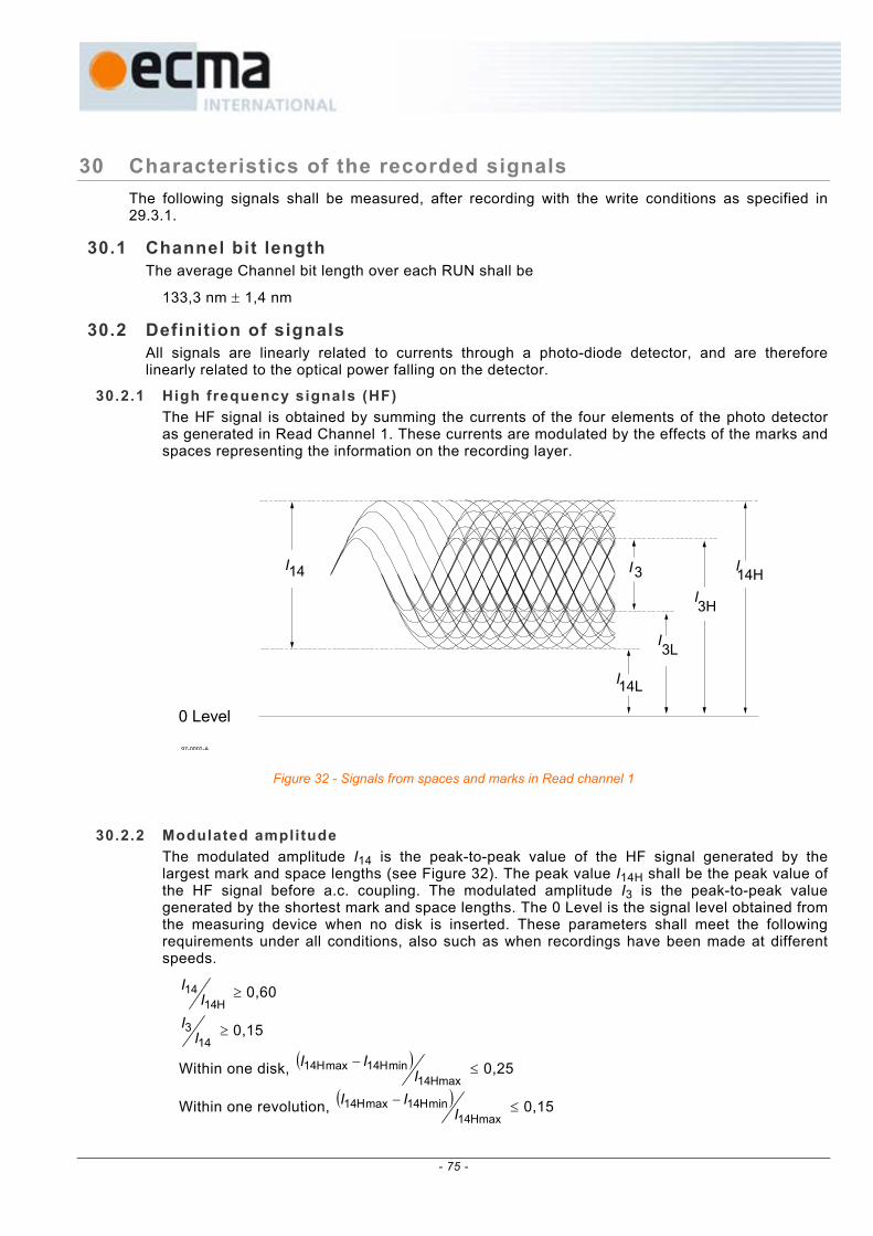
30 Characteristics of the recorded signals The following signals shall be measured, after recording with the write conditions as specified in 29.3.1.
30.1 Channel bit length The average Channel bit length over each RUN shall be
133,3 nm ± 1,4 nm
30.2 Definition of signals All signals are linearly related to currents through a photo-diode detector, and are therefore linearly related to the optical power falling on the detector.
30.2.1 High frequency signals (HF) The HF signal is obtained by summing the currents of the four elements of the photo detector as generated in Read Channel 1. These currents are modulated by the effects of the marks and spaces representing the information on the recording layer.
97-0002-A
0 Level
I
I
I
I
I 14
14L
3L
3H
14HI 3
Figure 32 - Signals from spaces and marks in Read channel 1
30.2.2 Modulated amplitude The modulated amplitude I14 is the peak-to-peak value of the HF signal generated by the largest mark and space lengths (see Figure 32). The peak value I14H shall be the peak value of the HF signal before a.c. coupling. The modulated amplitude I3 is the peak-to-peak value generated by the shortest mark and space lengths. The 0 Level is the signal level obtained from the measuring device when no disk is inserted. These parameters shall meet the following requirements under all conditions, also such as when recordings have been made at different speeds.
H1414
II ≥ 0,60
143
II ≥ 0,15
Within one disk, ( )Hmax14
minH14maxH14I
II − ≤ 0,25
Within one revolution, ( )Hmax14
minH14maxH14I
II − ≤ 0,15
- 75 -

30.2.3 Signal asymmetry The signal asymmetry shall meet the following requirement:
0,15220,0514
3L3H14L14H
+≤
+−
+
≤−I
IIII
30.2.4 Normalized Slicing Level jump Between any 2 consecutive ECC Blocks, the Normalized Slicing Level (NSL) jump shall be:
( ) ( )( ) ( ) 35,0
3L,13H,13L,23H,2
3L,13H,13L,23H,2 ≤−+−
+−+
IIIIIIII
where I3H,1 and I3L,1 are the I3 levels just before the linking position and I3H,2 and I3L,2 are the I3 levels just after the linking position.
This requirement shall be fulfilled also when the 2 ECC Blocks have been recorded at different speeds.
30.2.5 Jitter Jitter is the standard deviation σ of the time variations of the binary read signal. This binary read signal is created by a slicer, after feeding the HF signal from the HF read channel through an equalizer and LPF (see Annex D). The jitter of the leading and trailing edges is measured relative to the PLL clock and normalized by the Channel bit clock period.
The jitter shall be measured at the Reference velocity using the circuit specified in Annex D.
The jitter measurement shall be using the conditions specified in 29.4.
The measured jitter shall not exceed 9,0 %.
30.2.6 Track Cross signal The Track Cross signal is the filtered sinusoidal sum signal (I1 + I2) in Read Channel 1 when the focus of the optical beam crosses the tracks. The Track Cross signal shall meet the following requirement:
( )
( ) 0,13max21
pp21≥
+
+
II
II
30.3 Read stability When read with a read power of 0,8 mW at a temperature of 55 °C, all parameters specified in 30.2.2 to 30.2.6 shall be within their specified ranges after 1 000 000 repeated reads. NOTE Reading with the same read power at lower speeds than the reference speed might degrade the read stability.
- 76 -

31 Additional testing conditions Recorded +R disks compliant with this +R Ecma Standard shall also fulfil the following basic signal specifications when measured with the Pick Up Head according to the ECMA-267 Standard.
31.1 Test environment All conditions are the same as in 29.1 to 29.2.5 except for the following.
31.1.1 Optics The focused optical beam used for reading data shall have the following properties:
a) Wavelength (λ) 650 nm ± 5 nm b) Numerical aperture of the objective lens (NA) 0,60 ± 0,01 c) The objective lens shall be compensated for spherical aberrations caused by a parallel
substrate with nominal thickness (0,6 mm) and nominal refractive index (1,55). d) Wave front aberration 0,033 × λ rms max. e) Light intensity at the rim of the pupil of the 60 % to 70 % of the maximum
objective lens intensity in the radial direction and over 90 % in the tangential direction.
f) Polarization of the light Circular g) Read power 0,7 mW ± 0,1 mW h) Relative Intensity Noise (RIN )* of laser diode -134 dB/Hz max.
*RIN (dB/Hz) = 10 log [(a.c. light power density / Hz) / d.c. light power]
31.2 Definition of signals For the definition of the following signals see 30.2 and the underlying subclauses.
31.2.1 Modulated amplitude
H1414
II ≥ 0,60
143
II ≥ 0,15
Within one disk, ( )Hmax14
minH14maxH14I
II − ≤ 0,33 (with PBS)
Within one disk, ( )Hmax14
minH14maxH14I
II − ≤ 0,20 (without PBS)
( )Within one revolution, Hmax14
minH14maxH14I
II − ≤ 0,15 (with PBS)
( )Within one revolution, Hmax14
minH14maxH14I
II − ≤ 0,10 (without PBS)
31.2.2 Signal asymmetry
0,15220,0514
3L3H14L14H
+≤
+−
+
≤−I
IIII
31.2.3 Jitter The jitter shall be measured at the Reference velocity using the circuit specified in Annex D. The jitter measurement shall be using the conditions specified in 29.4. The measured jitter shall not exceed 9,0 %.
- 77 -

31.2.4 Track Cross signal
( )
( ) 10,0max21
pp21≥
+
+
II
II
31.2.5 Differential phase tracking error signal The output currents of the four quadrants of the split photo detector shown in Figure 33 are identified by Ia, Ib, Ic, and Id.
The differential phase tracking error signal shall be derived from the phase differences between the sum of the currents of diagonal pairs of photo detector elements when the light beam crosses the tracks:
{Phase (Ia+Ic) - Phase(Ib+Id)}, see Figure 34 and Annex E.
The phase difference signals shall be low-pass filtered with fc(-3 db) of 30 kHz.
This differential phase tracking error signal shall meet the following requirements (see Figure 34):
Amplitude
At the positive 0 crossing T∆t shall be in the range 0,5 to 1,1 at 0,10 µm radial offset, where
∆t is the average time difference derived from the phase differences between the sum of the currents of diagonal pairs of photo detector elements, and T is the Channel bit clock period.
Asymmetry (see Figure 34)
The asymmetry shall meet the following requirement:
2,021
21 ≤+
−
TTTT
where T1 is the positive peak value of T∆t
and T2 is the negative peak value of T∆t
Light beam
Tangential direction I
I I
I 97-0047-A
a b
d c
Figure 33 - Quadrant photo detector
∆tT
0 Level -Tp Tp0
T1
T2
Radial spot displacementTp: Track pitch
Figure 34 - Differential phase tracking error signal
- 78 -
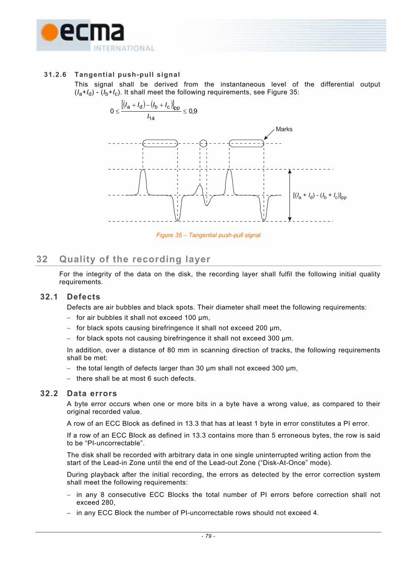
31.2.6 Tangential push-pull signal This signal shall be derived from the instantaneous level of the differential output (Ia+Id) - (Ib+Ic). It shall meet the following requirements, see Figure 35:
( ) ( )[ ]
9,0014
ppcbda≤
+−+≤
I
IIII
Marks
[( + ) - ( + )]I I I Ia d b c pp
Figure 35 – Tangential push-pull signal
32 Quality of the recording layer For the integrity of the data on the disk, the recording layer shall fulfil the following initial quality requirements.
32.1 Defects Defects are air bubbles and black spots. Their diameter shall meet the following requirements: − for air bubbles it shall not exceed 100 µm, − for black spots causing birefringence it shall not exceed 200 µm, − for black spots not causing birefringence it shall not exceed 300 µm.
In addition, over a distance of 80 mm in scanning direction of tracks, the following requirements shall be met: − the total length of defects larger than 30 µm shall not exceed 300 µm, − there shall be at most 6 such defects.
32.2 Data errors A byte error occurs when one or more bits in a byte have a wrong value, as compared to their original recorded value.
A row of an ECC Block as defined in 13.3 that has at least 1 byte in error constitutes a PI error.
If a row of an ECC Block as defined in 13.3 contains more than 5 erroneous bytes, the row is said to be “PI-uncorrectable”.
The disk shall be recorded with arbitrary data in one single uninterrupted writing action from the start of the Lead-in Zone until the end of the Lead-out Zone (“Disk-At-Once” mode).
During playback after the initial recording, the errors as detected by the error correction system shall meet the following requirements:
− in any 8 consecutive ECC Blocks the total number of PI errors before correction shall not exceed 280,
− in any ECC Block the number of PI-uncorrectable rows should not exceed 4.
- 79 -

Section 7 - Characteristics of user data
33 Method of testing Clause 34 describes a series of measurements to test conformance of the user data on the disk with this Ecma Standard. It checks the legibility of the user-written data. The data is assumed to be arbitrary. The data may have been written by any drive in any operating environment (see 8.1.2). The read tests shall be performed on the Reference Drive as defined in Clause 9.
Whereas Clause 29 disregards defects, Clause 34 includes them as an unavoidable deterioration of the read signals. The severity of a defect is determined by the correctability of the ensuing errors by the error detection and correction circuit in the read channel defined below. The requirements in Clause 34 define a minimum quality of the data, necessary for data interchange.
33.1 Environment All signals in 34.1 to 34.2 shall be within their specified ranges with the disk in any environment in the range of allowed operating environments defined in 8.1.2. It is recommended that before testing, the entrance surface of the disk shall be cleaned according to the instructions of the manufacturer of the disk.
33.2 Reference Drive All signals specified in Clause 34 shall be measured in the indicated channels of the Reference Drive as defined in Clause 9. The drive shall have the following characteristics for the purpose of these tests:
33.2.1 Optics and mechanics The focused optical beam shall have the properties already defined in 9.2 a) to i). The disk shall rotate as specified in 9.5.
33.2.2 Read power The optical power incident on the entrance surface of the disk (used for reading the information) shall be 0,7 mW ± 0,1 mW.
33.2.3 Read channels The drive shall have two read channels. Read Channel 1 gives a signal (I1 + I2) related to the total amount of light in the exit pupil of the objective lens. Read Channel 2 gives a signal (I1 - I2) related to the difference in the amount of light in the two halves of the exit pupil of the objective lens. These channels can be implemented as given in 9.3 and 9.6.
The signal from Read channel 1 is equalized and filtered before processing. The threshold level for binarizing the read signal shall be controlled to minimize the effects of mark and space size changes due to parameter variations during writing. For measurement of the disk quality as specified in Clause 34, the equalizer, filter and slicer, and the characteristics of the PLL shall be the same as specified in Annex D for the jitter measurement.
33.2.4 Error correction Correction of errors in the data bytes shall be carried out by an error detection and correction system based on the definition in 13.3.
33.2.5 Tracking During the measurement of the signals, the axial tracking error between the focus of the optical beam and the recording layer shall not exceed
emax(axial) = 0,20 µm
and the radial tracking error between the focus of the optical beam and the centre of a track shall not exceed
emax(radial) = 0,022 µm
- 80 -

34 Minimum quality of a Recording Unit This Clause specifies the minimum quality of the data of a Recording Unit as required for data interchange. The quality shall be measured on the Reference Drive as defined in Clause 9 and Annex D.
A byte error occurs when one or more bits in a byte have a wrong value, as detected by the ECC and/or EDC circuits.
34.1 Tracking The focus of the optical beam shall not jump tracks unintentionally.
34.2 User-written data The user-written data in a Recording Unit as read in Read channel 1 shall not contain any byte errors that cannot be corrected by the error correction defined in 13.3.
- 81 -

- 82 -

Annex A (normative)
80 mm +R disk
The +R System also allows an 80 mm disk with capacities of 1,46 Gbytes and 2,92 Gbytes. All mechanical, physical and optical characteristics shall be equal to those of the 120 mm disks specified in this document, except for the following items:
see: 10.2 Overall dimensions
The disk shall have an overall diameter d1 = 80,00 mm ± 0,30 mm
see: 10.7 Information Zone
The Information Zone shall extend from diameter d6 to diameter
d7 = 77,5 mm min.
This Zone consists of the Lead-in Zone, the Data Zone, the Lead-out Zone and the Inner and Outer Drive Areas (see also Clause 15).
see: 11.1 Mass
The mass of the disk shall be in the range of 6,0 g to 9,0 g.
see: 11.2 Moment of inertia
The moment of inertia of the disk, relative to its rotation axis, shall not exceed 0,010 g⋅m2.
see: 11.3 Dynamic imbalance
The dynamic imbalance of the disk, relative to its rotation axis, shall not exceed 1,5 g⋅mm.
see: 14.1 Track shape
The tracks shall be continuous in the Information Zone. The groove tracks shall start at a radius of 22,0 mm max. and end at a radius of 38,75 mm min.
see: 14.4.1.1 ADIP word structure, bit 2 to 23
Physical Address (0379CC), which is the first address corresponding to the Lead-out Zone, shall be located at a radius ≤ 38,0 mm.
see: 14.4.2.1 General information - Bytes 0 to 31
Byte 1 – Disk size and maximum transfer rate Bits b7 to b4 shall specify the disk size, they shall be set to 0001, indicating a 80 mm disk
Bytes 4 to 15 – Data Zone allocation Bytes 9 to 11 shall be set to (0DE72F) to specify PSN 911 151 as the last possible Physical Sector of the Data Zone.
- 83 -

see: 16 Layout of the Information Zone of a Single-session disk
Table 6 - Layout of a ful ly recorded Single-session disk (see also Annex A)
Description Nominal radius in mm
PSN of the first Physical Sector
Number of Physical Sectors
Inner Drive Area
all the same as 120 mm disk --- --- ---
Lead-in all the same as 120 mm disk --- --- ---
Data Data Zone start 24,000 mm (030000) 714 544 max
Buffer Zone 3 start 38,000 mm(at full capacity)
(0DE730) max 768
Lead-out Outer Disk Identification Zone (0DEA30) max 256
Guard Zone 2 (0DEB30) max 4 096 min
Outer Disk Administration Zone
start 38,082 mm (0DFB30) 4096
Outer Outer Disk Count Zone start 38,147 mm (0E0B30) 4096 Drive Area Outer Disk Test Zone start 38,212 mm (0E1B30) 16 384
Guard Zone 3 start 38,472 mmend ≥ 38,500 mm
(0E5B30) blank
see: 18.8.1 Physical format information
Bytes 4 to 15 – Data Zone allocation
Bytes 9 to 11 on a finalized Single Session disk (see 23.3): shall specify the Sector Number of the last Physical Sector of the Data Zone.
on a Multi-session disk (see Clause 22): shall be set to (0DE72F) to specify PSN 911 151 as the last possible Physical Sector on the disk for the storage of User Data.
see: 19 Data Zone
714 544 Physical Sectors for the storage of user data area.
The start radius of the Data Zone is determined by the location of ADIP Physical Address (00C000) and the maximum end radius is determined by the location of ADIP Physical Address (0379CC) (see 14.4.1.1, bit 2 to 23 and 13.7.1).
- 84 -
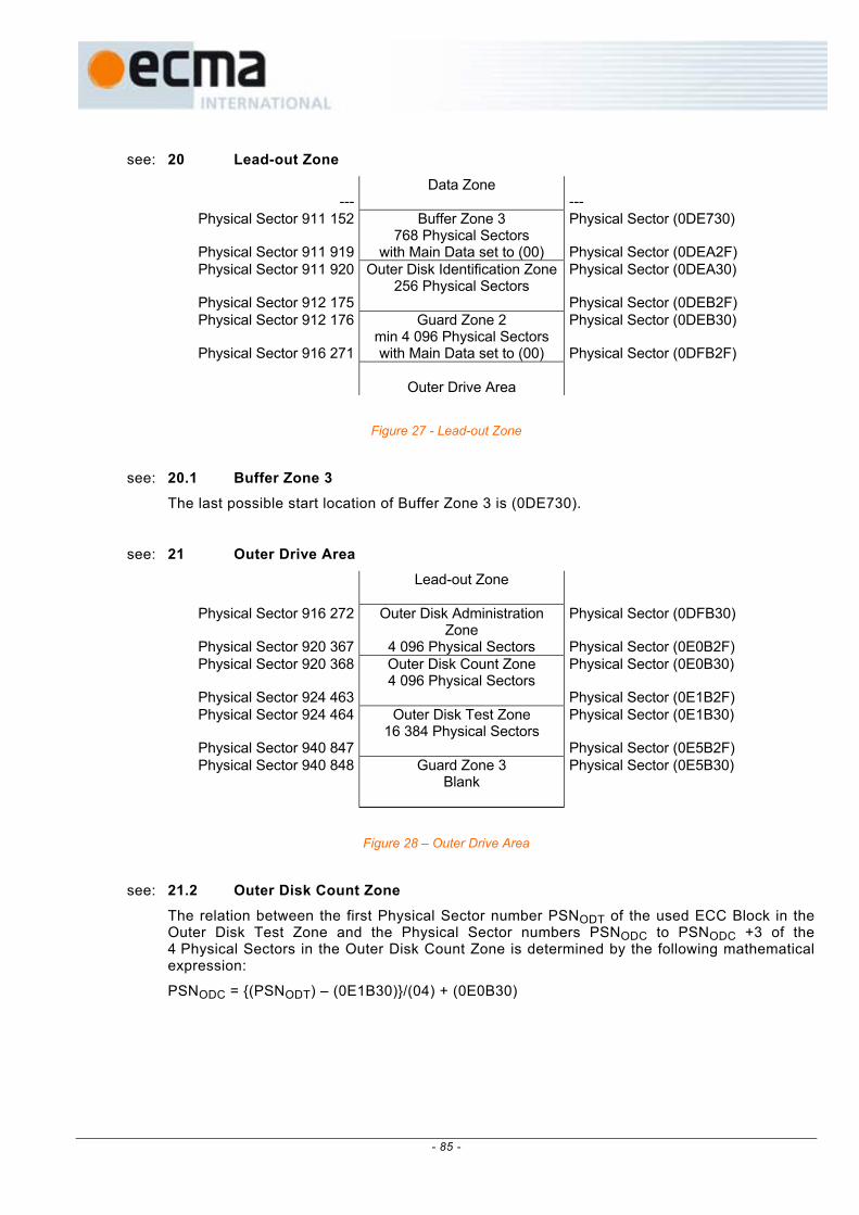
see: 20 Lead-out Zone
---
Data Zone
---
Physical Sector 911 152
Physical Sector 911 919
Buffer Zone 3 768 Physical Sectors
with Main Data set to (00)
Physical Sector (0DE730) Physical Sector (0DEA2F)
Physical Sector 911 920
Physical Sector 912 175
Outer Disk Identification Zone256 Physical Sectors
Physical Sector (0DEA30) Physical Sector (0DEB2F)
Physical Sector 912 176
Physical Sector 916 271
Guard Zone 2 min 4 096 Physical Sectors with Main Data set to (00)
Physical Sector (0DEB30) Physical Sector (0DFB2F)
Outer Drive Area
Figure 27 - Lead-out Zone
see: 20.1 Buffer Zone 3
The last possible start location of Buffer Zone 3 is (0DE730).
see: 21 Outer Drive Area
Lead-out Zone
Physical Sector 916 272
Physical Sector 920 367
Outer Disk Administration Zone
4 096 Physical Sectors
Physical Sector (0DFB30) Physical Sector (0E0B2F)
Physical Sector 920 368
Physical Sector 924 463
Outer Disk Count Zone 4 096 Physical Sectors
Physical Sector (0E0B30) Physical Sector (0E1B2F)
Physical Sector 924 464
Physical Sector 940 847
Outer Disk Test Zone 16 384 Physical Sectors
Physical Sector (0E1B30) Physical Sector (0E5B2F)
Physical Sector 940 848
Guard Zone 3 Blank
Physical Sector (0E5B30)
Figure 28 – Outer Drive Area
see: 21.2 Outer Disk Count Zone
The relation between the first Physical Sector number PSNODT of the used ECC Block in the Outer Disk Test Zone and the Physical Sector numbers PSNODC to PSNODC +3 of the 4 Physical Sectors in the Outer Disk Count Zone is determined by the following mathematical expression:
PSNODC = {(PSNODT) – (0E1B30)}/(04) + (0E0B30)
- 85 -

- 86 -

Annex B (normative)
Measurement of light reflectivity
B.1 Calibration method The reflectivity of a disk can be measured in several ways. The two most common methods are: − parallel method, − focused method.
For use in players the focused method with the help of a reference disk with known reflectivity is the most relevant and easiest one, while for the calibration of the reference disk the parallel method is easier.
When measuring the reflectivity in the focused way, only the light returned by the reflective layer of the disk (Rm) will fall onto the photo detector. The reflected light coming from the front surface of the disk and the light coming from the parasitic reflectance’s inside the disk will mainly fall outside the photo detector. Because in the parallel method only the “total” reflectance (R//) can be measured, a calculation is needed to determine the “main” reflectance from the reflective layer.
A good reference disk shall be chosen, for instance 0,6 mm glass disk with a golden reflective mirror. This reference disk shall be measured by a parallel beam as shown in Figure B.1
Rs
R
Rint
R//
RrIB
s
m
Figure B.1 - Reflectivity calibration
In this Figure the following applies: R = reflectivity of the recording layer (including the double pass substrate transmission) rs = reflectivity of the entrance surface
Rref = reflectivity as measured by the focussed beam (is by definition = B
mI
R )
IB = incident beam Rs = reflectance caused by the reflectivity of the entrance surface Rm = main reflectance caused by the reflectivity of the recording layer Rint = reflectance caused by the internal reflectances between the entrance surface and the
recording layer R// = measured value (Rs + Rm + Rint)
- 87 -

The reflectivity of the entrance surface is defined by:
2
s 11
+−
=nnr , where n is the index of refraction of the substrate.
The main reflectance Rm = R// - Rs -Rint which leads to:
( )
−×−
−×−
==
B
//s
sB
//2s
B
mref
21
1
IRr
rIRr
IRR
The reference disk shall be measured on a reference drive. The total detector current (I1 + I2) obtained from the reference disk, and measured by the focused beam is equated to Rm as determined above.
Now the arrangement is calibrated and the focused reflectivity is a linear function of the reflectivity of the recording layer and the double pass substrate transmission, independently from the reflectivity of the entrance surface.
B.2 Measuring method Reflectivity in the unrecorded Information Zone A method of measuring the reflectivity using the reference drive.
(1) Measure the total detector current (I1 + I2)s from the reference disk with calibrated reflectivity Rref.
(2) Measure the total detector current (I1 + I2)g from a groove track in an area of the disk under investigation where the groove track and the two adjacent tracks on each side of the track to be measured have not been recorded.
(3) Calculate the unrecorded disk reflectivity Rd as follows ( )( ) ref
s21
g21d R
II
IIR ×
+
+=
Reflectivity in the recorded Information Zone A method of measuring the reflectivity using the reference drive.
(1) Measure the total detector current (I1 + I2)s from the reference disk with calibrated reflectivity Rref.
(2) Measure I14H from a recorded groove track in an area of the disk under investigation where at least the two adjacent tracks on each side of the track to be measured have been recorded.
(3) Calculate the recorded disk reflectivity R14H as follows:
( ) refs21
14H14H R
IIIR ×+
=
- 88 -

Annex C (normative)
Measurement of birefringence
C.1 Principle of the measurement In order to measure the birefringence, circularly polarized light in a parallel beam is used. The phase retardation is measured by observing the ellipticity of the reflected light.
θ
a
b
radial direction
Figure C.1 - Ellipse with ellipticity e = b/a and orientation θ
The orientation θ of the ellipse is determined by the orientation of the optical axis
θ = γ - π/4 (1)
where γ is the angle between the optical axis and the radial direction.
The ellipticity, e = b/a, is a function of the phase retardation δ
−π
= δe22
1tan (2)
When the phase retardation δ is known the birefringence BR can be expressed as a fraction of the wavelength
nm2
δBRπ
λ= (3)
Thus, by observing the elliptically polarized light reflected from the disk, the birefringence can be measured and the orientation of the optical axis can be assessed as well.
C.2 Measurements conditions The measurement of the birefringence specified above shall be made under the following conditions.
- 89 -

Mode of measurement in reflection, double pass through the substrate.
Wavelength λ of the laser light 640 nm ± 15 nm Beam diameter (FWHM) 1,0 mm ± 0,2 mm Angle β of incidence in radial direction relative to the radial plane perpendicular to Reference Plane P
7,0° ± 0,2°
Disk mounting horizontally Rotation less than 1 Hz Temperature and relative humidity as specified in 8.1.1
C.3 Example of a measurement set-up Whilst this Ecma Standard does not prescribe a specific device for measuring birefringence, the device shown schematically in Figure C.2 as an example, is well suited for this measurement.
disc
λ/4 plate
polarizer
laser
rotating analyzer
collimator lens
photo detector
β
Figure C.2 - Example of a device for the measurement of birefringence
Light from a laser source, collimated into a polarizer ( extinction ratio ≈ 10-5 ), is made circular by a λ/4 plate. The ellipticity of the reflected light is analyzed by a rotating analyzer and a photo detector. For every location on the disk, the minimum and the maximum values of the intensity are measured. The ellipticity can then be calculated as
e2 = max
minI
I (4)
Combining equations (2), (3), and (4) yields
max
minarctan4 I
IBRπλ
−λ
=
This device can be easily calibrated as follows − Imin is set to 0 by measuring a polarizer or a λ/ 4 plate, − Imin = Imax when measuring a mirror
Apart of the d.c. contribution of the front surface reflection, a.c. components may occur, due to the interference of the reflection(s) of the front surface with the reflection(s) from the recording layer. These a.c. reflectivity effects are significant only if the disk substrate has an extremely accurate flatness and if the light source has a high coherence.
- 90 -
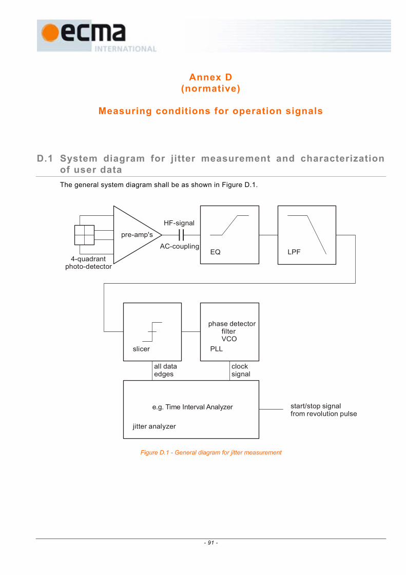
Annex D (normative)
Measuring conditions for operation signals
D.1 System diagram for jitter measurement and characterization of user data The general system diagram shall be as shown in Figure D.1.
pre-amp's
4-quadrantphoto-detector
HF-signal
AC-couplingLPFEQ
slicer PLL
jitter analyzer
all dataedges
clock signal
phase detector filter VCO
start/stop signalfrom revolution pulse
e.g. Time Interval Analyzer
Figure D.1 - General diagram for jitter measurement
- 91 -
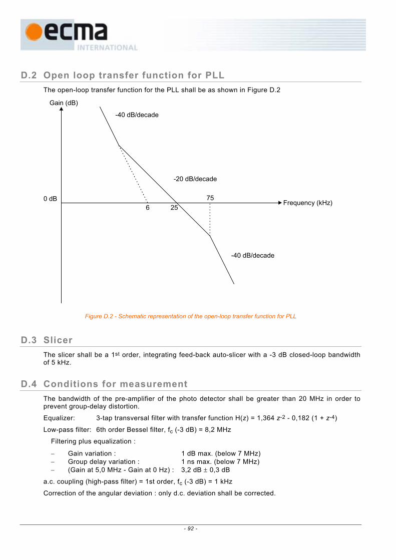
D.2 Open loop transfer function for PLL The open-loop transfer function for the PLL shall be as shown in Figure D.2
6 2575
Gain (dB)
0 dB
-40 dB/decade
-40 dB/decade
-20 dB/decade
Frequency (kHz)
Figure D.2 - Schematic representation of the open-loop transfer function for PLL
D.3 Slicer The slicer shall be a 1st order, integrating feed-back auto-slicer with a -3 dB closed-loop bandwidth of 5 kHz.
D.4 Conditions for measurement The bandwidth of the pre-amplifier of the photo detector shall be greater than 20 MHz in order to prevent group-delay distortion.
Equalizer: 3-tap transversal filter with transfer function H(z) = 1,364 z-2 - 0,182 (1 + z-4)
Low-pass filter: 6th order Bessel filter, fc (-3 dB) = 8,2 MHz
Filtering plus equalization :
− Gain variation : 1 dB max. (below 7 MHz) − Group delay variation : 1 ns max. (below 7 MHz) − (Gain at 5,0 MHz - Gain at 0 Hz) : 3,2 dB ± 0,3 dB
a.c. coupling (high-pass filter) = 1st order, fc (-3 dB) = 1 kHz
Correction of the angular deviation : only d.c. deviation shall be corrected.
- 92 -
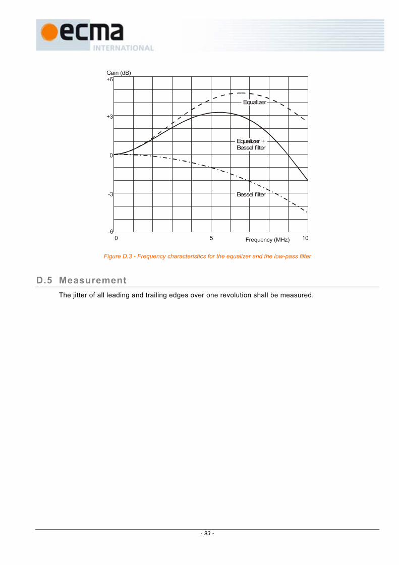
Gain (dB)+6
+3
0
-3
-6Frequency (MHz)0 5 10
Equalizer
Equalizer +Bessel filter
Bessel filter
Figure D.3 - Frequency characteristics for the equalizer and the low-pass filter
D.5 Measurement The jitter of all leading and trailing edges over one revolution shall be measured.
- 93 -

- 94 -
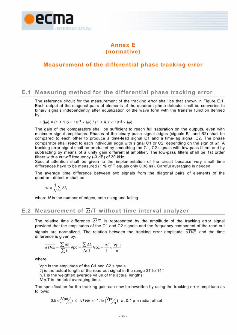
Annex E (normative)
Measurement of the differential phase tracking error
E.1 Measuring method for the differential phase tracking error The reference circuit for the measurement of the tracking error shall be that shown in Figure E.1. Each output of the diagonal pairs of elements of the quadrant photo detector shall be converted to binary signals independently after equalization of the wave form with the transfer function defined by:
H(iω) = (1 + 1,6 × 10⁻⁷ × iω) / (1 + 4,7 × 10⁻⁸ × iω)
The gain of the comparators shall be sufficient to reach full saturation on the outputs, even with minimum signal amplitudes. Phases of the binary pulse signal edges (signals B1 and B2) shall be compared to each other to produce a time-lead signal C1 and a time-lag signal C2. The phase comparator shall react to each individual edge with signal C1 or C2, depending on the sign of ∆ti. A tracking error signal shall be produced by smoothing the C1, C2 signals with low-pass filters and by subtracting by means of a unity gain differential amplifier. The low-pass filters shall be 1st order filters with a cut-off frequency (-3 dB) of 30 kHz. Special attention shall be given to the implementation of the circuit because very small time differences have to be measured (1 % of T equals only 0.38 ns). Careful averaging is needed.
The average time difference between two signals from the diagonal pairs of elements of the quadrant detector shall be
∑ ∆=∆ itNt 1
where N is the number of edges, both rising and falling.
E.2 Measurement of t∆ /T without time interval analyzer
The relative time difference /Tt∆ is represented by the amplitude of the tracking error signal provided that the amplitudes of the C1 and C2 signals and the frequency component of the read-out signals are normalized. The relation between the tracking error amplitude TVE∆ and the time difference is given by:
nVpc
TVpc
nTVpc i
i
i ×∆
=∆
=∆
=∆ ∑∑∑ t
Nt
Tt
TVE
where:
Vpc is the amplitude of the C1 and C2 signals Ti is the actual length of the read-out signal in the range 3T to 14T n.T is the weighted average value of the actual lengths N.n.T is the total averaging time.
The specification for the tracking gain can now be rewritten by using the tracking error amplitude as follows:
)nVpc(1.1)n
Vpc(0.5 ×≤∆≤× TVE at 0.1 µm radial offset.
- 95 -
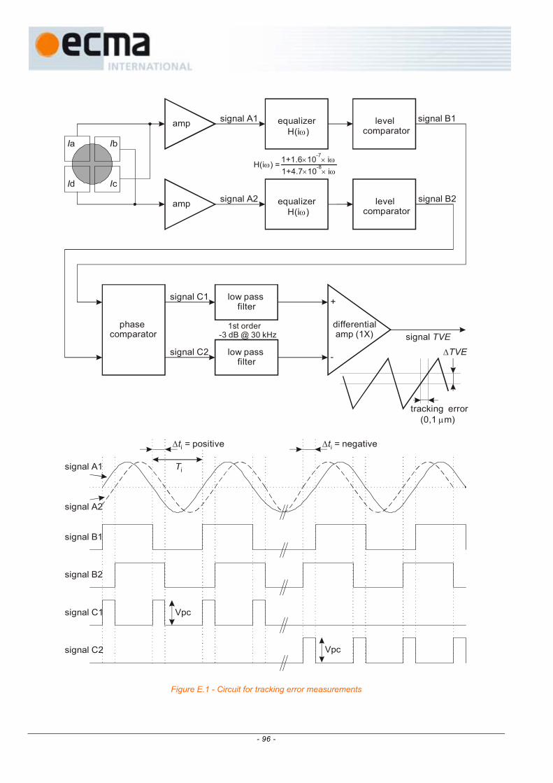
Ia Ib
Id Ic
amp
amp
equalizer H(i )ω
equalizer H(i )ω
levelcomparator
levelcomparator
phasecomparator
low pass filter
low pass filter
differential amp (1X)
+
-
signal A1 signal B1
signal B2
signal C1
signal C2
signal A2
signal TVE
signal B1
signal A1
signal A2
signal B2
signal C1
signal C2
∆ti = negative∆ti = positive
Vpc
Vpc
Ti
tracking error (0,1 m)µ
∆TVE
1+1.6 10 i-7ω× × H(i ) =ω
1+4.7 10 i-8ω× ×
1st order-3 dB @ 30 kHz
Figure E.1 - Circuit for tracking error measurements
- 96 -
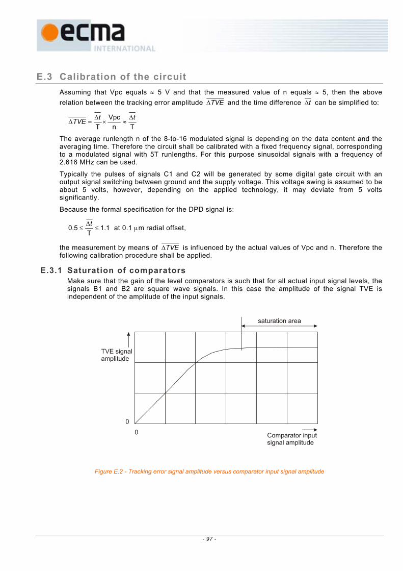
E.3 Calibration of the circuit Assuming that Vpc equals ≈ 5 V and that the measured value of n equals ≈ 5, then the above relation between the tracking error amplitude TVE∆ and the time difference t∆ can be simplified to:
TnVpc
TttTVE ∆
≈×∆
=∆
The average runlength n of the 8-to-16 modulated signal is depending on the data content and the averaging time. Therefore the circuit shall be calibrated with a fixed frequency signal, corresponding to a modulated signal with 5T runlengths. For this purpose sinusoidal signals with a frequency of 2.616 MHz can be used.
Typically the pulses of signals C1 and C2 will be generated by some digital gate circuit with an output signal switching between ground and the supply voltage. This voltage swing is assumed to be about 5 volts, however, depending on the applied technology, it may deviate from 5 volts significantly.
Because the formal specification for the DPD signal is:
1.1T
0.5 ≤∆
≤t at 0.1 µm radial offset,
the measurement by means of TVE∆ is influenced by the actual values of Vpc and n. Therefore the following calibration procedure shall be applied.
E.3.1 Saturation of comparators Make sure that the gain of the level comparators is such that for all actual input signal levels, the signals B1 and B2 are square wave signals. In this case the amplitude of the signal TVE is independent of the amplitude of the input signals.
saturation area
Comparator inputsignal amplitude
TVE signalamplitude
00
Figure E.2 - Tracking error signal amplitude versus comparator input signal amplitude
- 97 -

E.3.2 Correction for n and Vpc Because of the above mentioned deviations of n and Vpc, and possibly some other circuit parameters, a correction factor K has to be determined, such that:
/Tt∆ (real) = K × TVE∆ (measured).
This can be achieved in the following way:
a) Generate two sinusoidal signals A1 and A2 of frequency 2.616 MHz with a phase difference, and inject them into the two equalizer circuits.
b) Measure the relation between T/t∆ and TVE∆ , and determine K from Figure E.3:
(measured)d)/T(injecteK
TVEt
∆
∆= . Now the set-up is ready for use.
0 0.2 0.4 0.6 0.8 1.0 1.2∆t / T
∆TVE
0
0.2
0.4
0.6
0.8
1.0
1.2theoretical line forVpc=5V and n=5
example of measured line
Figure E.3 - TVE∆ versus /Tt∆
- 98 -

Annex F (normative)
The write pulse wave form for testing
For different speed ranges, different write strategies can be used. This version of this document specifies 2 options: − a pulsed write strategy, where each single mark is created by a number of subsequent separated short
pulses, − a blocked write strategy, where each single mark is created by one continuous pulse.
F.1 Pulsed write strategy The write pulse waveform obtained from the NRZI data and the channel clock is shown in Figure F.1. It consists of N-2 pulses, where N is the length of the NRZI pulse expressed in channel clock cycles.
The write pulse waveform for writing marks of length N = 3 consists of only the top pulse (Ttop). The write pulse waveform for writing marks of length N ≥ 4 consist of the top pulse (Ttop), N-4 multi-pulses (Tmp) and the last pulse (Tlp).
Pw
Pb
TtopTmp Tmp
Tlp
dTle
dTtop
TW2TWNRZI channel bits
0 mW
Figure F.1 - Write pulse waveform
The nominal pulse width times Tmp and Tlp shall be as indicated in the Physical format information in Table 3 and in 14.4.2.2. The duration can be dependent on the writing speed:
Tmp = m × 161 TW with m = 4, 5, .. or 14 (0,25 TW ≤ Tmp ≤ 0,875 TW)
Tlp = n × 161 TW with n = 4, 5, .. or 24 (0,25 TW ≤ Tlp ≤ 1,5 TW)
The laser power shall be switched to bias level between each pair of separated pulses for at least 16
2 TW.
The nominal pulse width time Ttop, is dependent upon the length of the current mark (cm). It shall be as indicated in the Physical format information in Table 3 and in 14.4.2.2. The duration can also be dependent on the writing speed:
- 99 -

Ttop (cm=3) = i × 161 TW with i = 4, 5, .. or 40 (0,25 TW ≤ Ttop ≤ 2,5 TW)
Ttop (cm≥4) = j × 161 TW with j = 4, 5, .. or 40 (0,25 TW ≤ Ttop ≤ 2,5 TW)
The nominal first pulse lead-time dTtop relative to the trailing edge of the second Channel bit of the NRZI data pulse, is dependent upon the length of the current mark (cm). It shall be as indicated in the Physical format information in Table 3 and in 14.4.2.2. The value of dTtop can also be dependent on the writing speed:
dTtop (cm=3) = p × 161 TW with p = 0, 1, .. or 24 (0,0 TW ≤ dTtop (cm=3) ≤ 1,5 TW)
dTtop (cm≥4) = q × 161 TW with q = 0, 1, .. or 24 (0,0 TW ≤ dTtop (cm≥4) ≤ 1,5 TW)
With the individual values for Ttop (cm=3) and dTtop (cm=3), the 3T mark can be enhanced and shifted for optimum resulting jitter. The widening of the 3T write pulse is: ∆T = {Ttop (cm=3) − Ttop (cm≥4)}, and the shift of the 3T write pulse is: δT = {dTtop (cm=3) − dTtop (cm≥4)}.
In principle the shift δT and the widening ∆T of the 3T pulse can be chosen independently. However because of limitations in certain implementations, for this version of this document there is one exception: if a shift of the 3T pulse is needed, such a shift shall be combined with a widening resulting in a symmetrical change of the 3T write pulse. Or in mathematical terms: if δT ≠0, then ∆T shall be = 2 × δT (see Figure F.2).
The position of the leading edge and hence the length of the first pulse may be corrected by dTle dependent upon the length of the previous space (ps). This feature is called “thermal balancing”. dTle shall be as indicated in the Physical format information in Table 3 and in 14.4.2.2. If the previous space is ≥4 channel clock cycles, then dTle shall be 0. The value of dTle can be dependent on the writing speed:
dTle (ps =3) = u × 116 TW with u = 0, 1, .. or 4 (0 ≤ dTle ≤ 0,25 TW)
(dTle will give a delay and reduce the length of the first pulse as indicated in Figure F.1)
The values for Pw, and Pb are determined according to the OPC algorithm (see Annex H). An example of the write pulse waveform is shown in Figure F.2.
3 Tmark
enhanced 3 Twrite pulse
reducedtop pulse
δT
dTle∆T/2
∆T/2
3 Tspace
8 Tmark
NRZI data
Figure F.2 - Example of a Multiple-pulse
F.2 Blocked write strategy The waveform for the blocked write strategy (see Figure F.3) is derived from the waveform for the pulsed write strategy by setting Tmp equal to TW (m = 16) and setting Ttop(cm≥4) equal to dTtop + TW (j = q + 16). Ttop(cm=3) can be optimised individually.
- 100 -

The write pulse waveform for writing marks of length N = 3 is a pulse with a length Ttop(cm=3). The write pulse waveform for writing marks of length N ≥ 4 is a pulse with a length dTtop(cm≥4) + (N-3)×TW + Tlp.
Especially at higher recording speeds, optimum cooling down of the recording layer after writing a mark may be needed. For this purpose the bias power shall be switched to Pc between the trailing edge of the write pulse and a quarter of the second Channel bit after the trailing edge of the NRZI data pulse. Pc shall be < 0,1 mW.
At higher recording speeds with a blocked write strategy also a power enhancement for the shorter marks might be needed. The additional power dPw shall only be applied for the 3T and 4T marks and shall extend over the full width of the write pulse waveform (see Figures F.3 and F.4). It shall be as indicated in the Physical format information in Table 5 and in 14.4.2.3.1.
dPw (cm=3) = w200
Py× with y = 0, 1, .. or 100 (0,00 Pw ≤ dPw ≤ 0,50 Pw)
dPw (cm=4) = w200
Pz× with z = 0, 1, .. or 100 (0,00 Pw ≤ dPw ≤ 0,50 Pw)
dPw (cm≥5) = 0
Pw
d wP
Pb PbPc
TtopTmp
Tmp
Tlp
dTle
dTtop
1.25TW
2TWTW
0 mW
NRZI channel bits
Figure F.3 – General blocked waveform
The nominal pulse width times Tmp and Tlp shall be as indicated in the Physical format information in Table 5 and in 14.4.2.3.1. The duration can be dependent on the writing speed:
Tmp = m × 161 TW with m = 16 (Tmp = 1,0 TW)
Tlp = n × 161 TW with n = 0, 1, .. or 16 (0,0 TW ≤ Tlp ≤ 1,0 TW)
The nominal pulse width time Ttop, is dependent upon the length of the current mark (cm). It shall be as indicated in the Physical format information in Table 5 and in 14.4.2.3.1. The duration can also be dependent on the writing speed:
Ttop (cm=3) = i × 161 TW with i = 16, 17, .. or 48 (1 TW ≤ Ttop ≤ 3 TW)
Ttop (cm≥4) = j × 161 TW with j = 16, 17, .. or 48 (1 TW ≤ Ttop ≤ 3 TW)
(j = q + 16, see at dTtop)
- 101 -

The nominal first pulse lead-time dTtop relative to the trailing edge of the second Channel bit of the NRZI data pulse, is dependent upon the length of the current mark (cm). It shall be as indicated in the Physical format information in Table 5 and in 14.4.2.3.1. The value of dTtop can also be dependent on the writing speed:
dTtop (cm=3) = p × 161 TW with p = 0, 1, .. or 32 (0,0 TW ≤ dTtop (cm=3) ≤ 2 TW)
dTtop (cm≥4) = q × 161 TW with q = 0, 1, .. or 32 (0,0 TW ≤ dTtop (cm≥4) ≤ 2 TW)
(q = j – 16, see at Ttop)
With the individual values for Ttop (cm=3) and dTtop (cm =3) the 3T mark can be adapted and shifted for optimum resulting jitter. The relative shift of the 3T write pulse is: δT = {dTtop (cm=3) − dTtop (cm≥4)}.
The position of the leading edge and hence the length of the first pulse may be corrected by dTle dependent upon the length of the previous space (ps). This feature is called “thermal balancing”. dTle shall be as indicated in the Physical format information in Table 5 and in 14.4.2.3.1. If the previous space is ≥4 channel clock cycles, then dTle shall be 0. The value of dTle can be dependent on the writing speed:
dTle (ps=3) = u × 161 TW with u = 0, 1, .. or 4 (0 ≤ dTle ≤ 0,25 TW)
(dTle will give a delay and reduce the length of the first pulse as indicated in Figure F.3)
The values for Pw, and Pb are determined according to the OPC algorithm (see Annex H).
Ttop,3
dTtop,3
dTtop,4
Ttop,4
Ttop,4 Tmp
TmpTmpTtop,4
Tlp
Tlp
Tlpetc.
1.25 TW
1.25 TW
1.25 TW
1.25 TW
dTle
d wP 3
d wP 4
Pc
Pc
Pc
Pc
Pb
Pb
Pb
3T mark
4T mark
5T mark
Figure F.4 - Examples of a “blocked” waveform
- 102 -
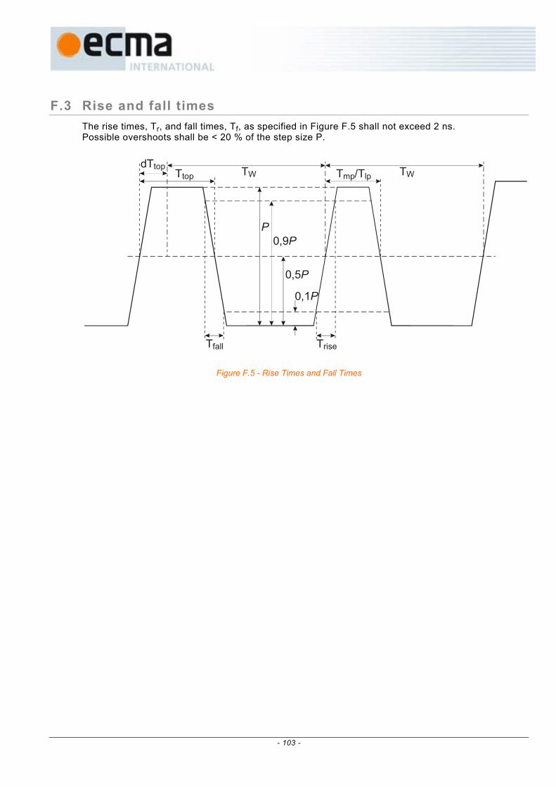
F.3 Rise and fall times The rise times, Tr, and fall times, Tf, as specified in Figure F.5 shall not exceed 2 ns. Possible overshoots shall be < 20 % of the step size P.
Ttop T /Tmp lpdTtop TWTW
TriseTfall
P0,9P
0,5P
0,1P
Figure F.5 - Rise Times and Fall Times
- 103 -

- 104 -

Annex G (normative)
8-to-16 Modulation
8-to-16 modulation shall satisfy RLL(2,10) requirements. The encoding system is shown in Figure G.1 with the conversion tables shown in Table G.1 and Table G.2.
Conversion Table
T
State, S(t)
8-bit byte, B(t) 16-bit Code Word, X(t)
Next State, S(t+1)
T = delay of one conversionWhere: X(t) = H{B(t), S(t)} X (t) = msb and X (t) = lsb S(t+1) = G{B(t), S(t)} H is the output function from the conversion tables G is the next-state function from the conversion tables
15 0
Figure G.1 - Code Word generating system
The States of the Code Words, X(t), shall be chosen to satisfy the RLL(2,10) requirements of a minimum of 2 ZEROs and a maximum of 10 ZEROs between ONEs of adjacent Code Words.
Code Word X(t) Next State X(t+1) Code Word X(t+1) Ends with 1 or no trailing ZEROs State 1 Starts with 2 to 9 leading ZEROs
Ends with 2 to 5 trailing ZEROs State 2 Starts with 1or up to 5 leading ZEROs and X15(t+1) , X3(t+1) = 0,0
Ends with 2 to 5 trailing ZEROs State 3 Starts with none or up to 5 leading ZEROsand X15(t+1) , X3(t+1) ≠ 0,0
Ends with 6 to 9 trailing ZEROs State 4 Starts with 1 or no leading ZEROs
Figure G.2 - Determination of States
Note that when decoding the recorded data, knowledge about the encoder is required to be able to reconstitute the original bytes. B(t) = H-1{X(t), S(t)} Because of the involved error propagation, such state-dependent decoding is to be avoided. In the case of this 8-to-16 modulation, the conversion tables have been chosen in such a way that knowledge about the State is not required in most cases. As can be gathered from the tables, in some cases, two 8-bit bytes, for
- 105 -
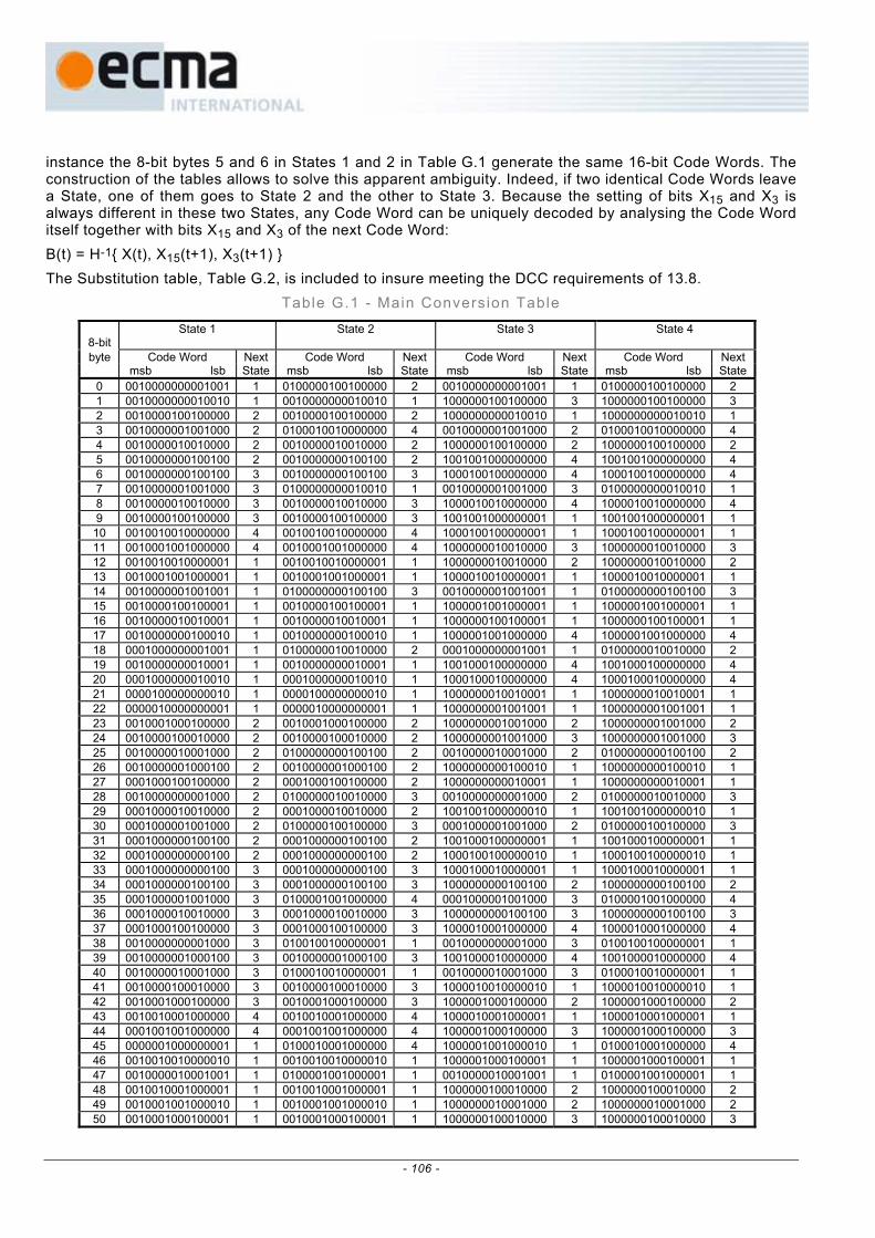
instance the 8-bit bytes 5 and 6 in States 1 and 2 in Table G.1 generate the same 16-bit Code Words. The construction of the tables allows to solve this apparent ambiguity. Indeed, if two identical Code Words leave a State, one of them goes to State 2 and the other to State 3. Because the setting of bits X15 and X3 is always different in these two States, any Code Word can be uniquely decoded by analysing the Code Word itself together with bits X15 and X3 of the next Code Word: B(t) = H-1{ X(t), X15(t+1), X3(t+1) } The Substitution table, Table G.2, is included to insure meeting the DCC requirements of 13.8.
Table G.1 - Main Conversion Table
8-bit
State 1
State 2
State 3
State 4
byte Code Word Next Code Word Next Code Word Next Code Word Next msb lsb State msb lsb State msb lsb State msb lsb State
0 0010000000001001 1 0100000100100000 2 0010000000001001 1 0100000100100000 2 1 0010000000010010 1 0010000000010010 1 1000000100100000 3 1000000100100000 3 2 0010000100100000 2 0010000100100000 2 1000000000010010 1 1000000000010010 1 3 0010000001001000 2 0100010010000000 4 0010000001001000 2 0100010010000000 4 4 0010000010010000 2 0010000010010000 2 1000000100100000 2 1000000100100000 2 5 0010000000100100 2 0010000000100100 2 1001001000000000 4 1001001000000000 4 6 0010000000100100 3 0010000000100100 3 1000100100000000 4 1000100100000000 4 7 0010000001001000 3 0100000000010010 1 0010000001001000 3 0100000000010010 1 8 0010000010010000 3 0010000010010000 3 1000010010000000 4 1000010010000000 4 9 0010000100100000 3 0010000100100000 3 1001001000000001 1 1001001000000001 1 10 0010010010000000 4 0010010010000000 4 1000100100000001 1 1000100100000001 1 11 0010001001000000 4 0010001001000000 4 1000000010010000 3 1000000010010000 3 12 0010010010000001 1 0010010010000001 1 1000000010010000 2 1000000010010000 2 13 0010001001000001 1 0010001001000001 1 1000010010000001 1 1000010010000001 1 14 0010000001001001 1 0100000000100100 3 0010000001001001 1 0100000000100100 3 15 0010000100100001 1 0010000100100001 1 1000001001000001 1 1000001001000001 1 16 0010000010010001 1 0010000010010001 1 1000000100100001 1 1000000100100001 1 17 0010000000100010 1 0010000000100010 1 1000001001000000 4 1000001001000000 4 18 0001000000001001 1 0100000010010000 2 0001000000001001 1 0100000010010000 2 19 0010000000010001 1 0010000000010001 1 1001000100000000 4 1001000100000000 4 20 0001000000010010 1 0001000000010010 1 1000100010000000 4 1000100010000000 4 21 0000100000000010 1 0000100000000010 1 1000000010010001 1 1000000010010001 1 22 0000010000000001 1 0000010000000001 1 1000000001001001 1 1000000001001001 1 23 0010001000100000 2 0010001000100000 2 1000000001001000 2 1000000001001000 2 24 0010000100010000 2 0010000100010000 2 1000000001001000 3 1000000001001000 3 25 0010000010001000 2 0100000000100100 2 0010000010001000 2 0100000000100100 2 26 0010000001000100 2 0010000001000100 2 1000000000100010 1 1000000000100010 1 27 0001000100100000 2 0001000100100000 2 1000000000010001 1 1000000000010001 1 28 0010000000001000 2 0100000010010000 3 0010000000001000 2 0100000010010000 3 29 0001000010010000 2 0001000010010000 2 1001001000000010 1 1001001000000010 1 30 0001000001001000 2 0100000100100000 3 0001000001001000 2 0100000100100000 3 31 0001000000100100 2 0001000000100100 2 1001000100000001 1 1001000100000001 1 32 0001000000000100 2 0001000000000100 2 1000100100000010 1 1000100100000010 1 33 0001000000000100 3 0001000000000100 3 1000100010000001 1 1000100010000001 1 34 0001000000100100 3 0001000000100100 3 1000000000100100 2 1000000000100100 2 35 0001000001001000 3 0100001001000000 4 0001000001001000 3 0100001001000000 4 36 0001000010010000 3 0001000010010000 3 1000000000100100 3 1000000000100100 3 37 0001000100100000 3 0001000100100000 3 1000010001000000 4 1000010001000000 4 38 0010000000001000 3 0100100100000001 1 0010000000001000 3 0100100100000001 1 39 0010000001000100 3 0010000001000100 3 1001000010000000 4 1001000010000000 4 40 0010000010001000 3 0100010010000001 1 0010000010001000 3 0100010010000001 1 41 0010000100010000 3 0010000100010000 3 1000010010000010 1 1000010010000010 1 42 0010001000100000 3 0010001000100000 3 1000001000100000 2 1000001000100000 2 43 0010010001000000 4 0010010001000000 4 1000010001000001 1 1000010001000001 1 44 0001001001000000 4 0001001001000000 4 1000001000100000 3 1000001000100000 3 45 0000001000000001 1 0100010001000000 4 1000001001000010 1 0100010001000000 4 46 0010010010000010 1 0010010010000010 1 1000001000100001 1 1000001000100001 1 47 0010000010001001 1 0100001001000001 1 0010000010001001 1 0100001001000001 1 48 0010010001000001 1 0010010001000001 1 1000000100010000 2 1000000100010000 2 49 0010001001000010 1 0010001001000010 1 1000000010001000 2 1000000010001000 2 50 0010001000100001 1 0010001000100001 1 1000000100010000 3 1000000100010000 3
- 106 -

Table G.1 - Main Conversion Table (cont inued)
51 0001000001001001 1 0100000100100001 0001000001001001 1 0100000100100001 1 52 0010000100100010 1 0010000100100010 1000000100100010 1 1000000100100010 1 53 0010000100010001 1 0010000100010001 1000000100010001 1 1000000100010001 1 54 0010000010010010 1 0010000010010010 1000000010010010 1 1000000010010010 1 55 0010000001000010 1 0010000001000010 1000000010001001 1 1000000010001001 1 56 0010000000100001 1 0010000000100001 1000000001000010 1 1000000001000010 1 57 0000100000001001 1 0100000010010001 0000100000001001 1 0100000010010001 1 58 0001001001000001 1 0001001001000001 1000000000100001 1 1000000000100001 1 59 0001000100100001 1 0001000100100001 0100000001001001 1 0100000001001001 1 60 0001000010010001 1 0001000010010001 1001001000010010 1 1001001000010010 1 61 0001000000100010 1 0001000000100010 1001001000001001 1 1001001000001001 1 62 0001000000010001 1 0001000000010001 1001000100000010 1 1001000100000010 1 63 0000100000010010 1 0000100000010010 1000000001000100 2 1000000001000100 2 64 0000010000000010 1 0000010000000010 0100000001001000 2 0100000001001000 2 65 0010010000100000 2 0010010000100000 1000010000100000 2 1000010000100000 2 66 0010001000010000 2 0010001000010000 1000001000010000 2 1000001000010000 2 67 0010000100001000 2 0100000000100010 0010000100001000 2 0100000000100010 1 68 0010000010000100 2 0010000010000100 1000000100001000 2 1000000100001000 2 69 0010000000010000 2 0010000000010000 1000000010000100 2 1000000010000100 2 70 0001000010001000 2 0100001000100000 0001000010001000 2 0100001000100000 2 71 0001001000100000 2 0001001000100000
1 1 1 1 1 1 1 1 1 1 1 1 1 1 2 2 1 2 2 2 2 0100000010001000 2 0100000010001000 2
72 0001000000001000 2 0100000100010000 2 2 0100000100010000 2 73 0001000100010000 2 0001000100010000 2 3 1000000001000100 3 74 0001000001000100 2 0001000001000100 2 3 0100000001001000 3 75 0000100100100000 2 0000100100100000 2 3 1000010000100000 3 76 0000100010010000 2 0000100010010000 2 3 1000001000010000 3 77 0000100001001000 2 0100000001000100 2 2
0001000000001000 1000000001000100 0100000001001000 1000010000100000 1000001000010000 0000100001001000 0100000001000100 2
78 0000100000100100 2 0000100000100100 2 1000000100001000 3 1000000100001000 3 79 0000100000000100 2 0000100000000100 2 1000000010000100 3 1000000010000100 3 80 0000100000000100 3 0000100000000100 3 0100000010001000 3 3 81 0000100000100100 3 0000100000100100 3 1000100001000000 4 1000100001000000 4 82 0000100001001000 3 0100000001000100 3 0000100001001000 3 0100000001000100 3 83 0000100010010000 3 0000100010010000 3 1000000010001000 3 1000000010001000 3 84 0000100100100000 3 0000100100100000 3 1001001001001000 2 1001001001001000 2 85 0001000000001000 3 0100000100010000 3 0001000000001000 3 0100000100010000 3 86 0001000001000100 3 0001000001000100 3 1001001000100100 2 1001001000100100 2 87 0001000010001000 3 0100001000100000 3 0001000010001000 3 0100001000100000 3 88 0001000100010000 3 0001000100010000 3 1001001001001000 3 1001001001001000 3 89 0001001000100000 3 0001001000100000 3 1001000010000001 1 1001000010000001 1 90 0010000000010000 3 0010000000010000 3 1000100100010010 1 1000100100010010 1 91 0010000010000100 3 0010000010000100 3 1000100100001001 1 1000100100001001 1 92 0010000100001000 3 0100000000010001 1 0010000100001000 3 0100000000010001 1 93 0010001000010000 3 0010001000010000 3 1000100010000010 1 1000100010000010 1 94 0010010000100000 3 0010010000100000 3 1000100001000001 1 1000100001000001 1 95 0000001000000010 1 0100100100000010 1 1000010010010010 1 0100100100000010 1 96 0000000100000001 1 0100100010000001 1 1000010010001001 1 0100100010000001 1 97 0010010010001001 1 0100010000100000 2 0010010010001001 1 0100010000100000 2 98 0010010010010010 1 0010010010010010 1 1001001000000100 2 1001001000000100 2 99 0010010001000010 1 0010010001000010 1 1001001000100100 3 1001001000100100 3 100 0010010000100001 1 0010010000100001 1 1000010001000010 1 1000010001000010 1 101 0010001001001001 1 0100010010000010 1 0010001001001001 1 0100010010000010 1 102 0010001000100010 1 0010001000100010 1 1000010000100001 1 1000010000100001 1 103 0010001000010001 1 0010001000010001 1 1000001001001001 1 1000001001001001 1 104 0010000100010010 1 0010000100010010 1 1000001000100010 1 1000001000100010 1 105 0010000010000010 1 0010000010000010 1 1000001000010001 1 1000001000010001 1 106 0010000100001001 1 0100001000010000 2 0010000100001001 1 0100001000010000 2 107 0010000001000001 1 0010000001000001 1 1000000100010010 1 1000000100010010 1 108 0001001001000010 1 0001001001000010 1 1000000100001001 1 1000000100001001 1 109 0001001000100001 1 0001001000100001 1 1000000010000010 1 1000000010000010 1 110 0001000100100010 1 0001000100100010 1 1000000001000001 1 1000000001000001 1 111 0001000100010001 1 0001000100010001 1 0100000010001001 1 0100000010001001 1 112 0001000010010010 1 0001000010010010 1 1001001001001001 1 1001001001001001 1 113 0001000001000010 1 0001000001000010 1 1001001000100010 1 1001001000100010 1 114 0001000010001001 1 0100010000100000 3 0001000010001001 1 0100010000100000 3 115 0001000000100001 1 0001000000100001 1 1001001000010001 1 1001001000010001 1 116 0000100100100001 1 0000100100100001 1 1001000100010010 1 1001000100010010 1
0100000010001000
- 107 -
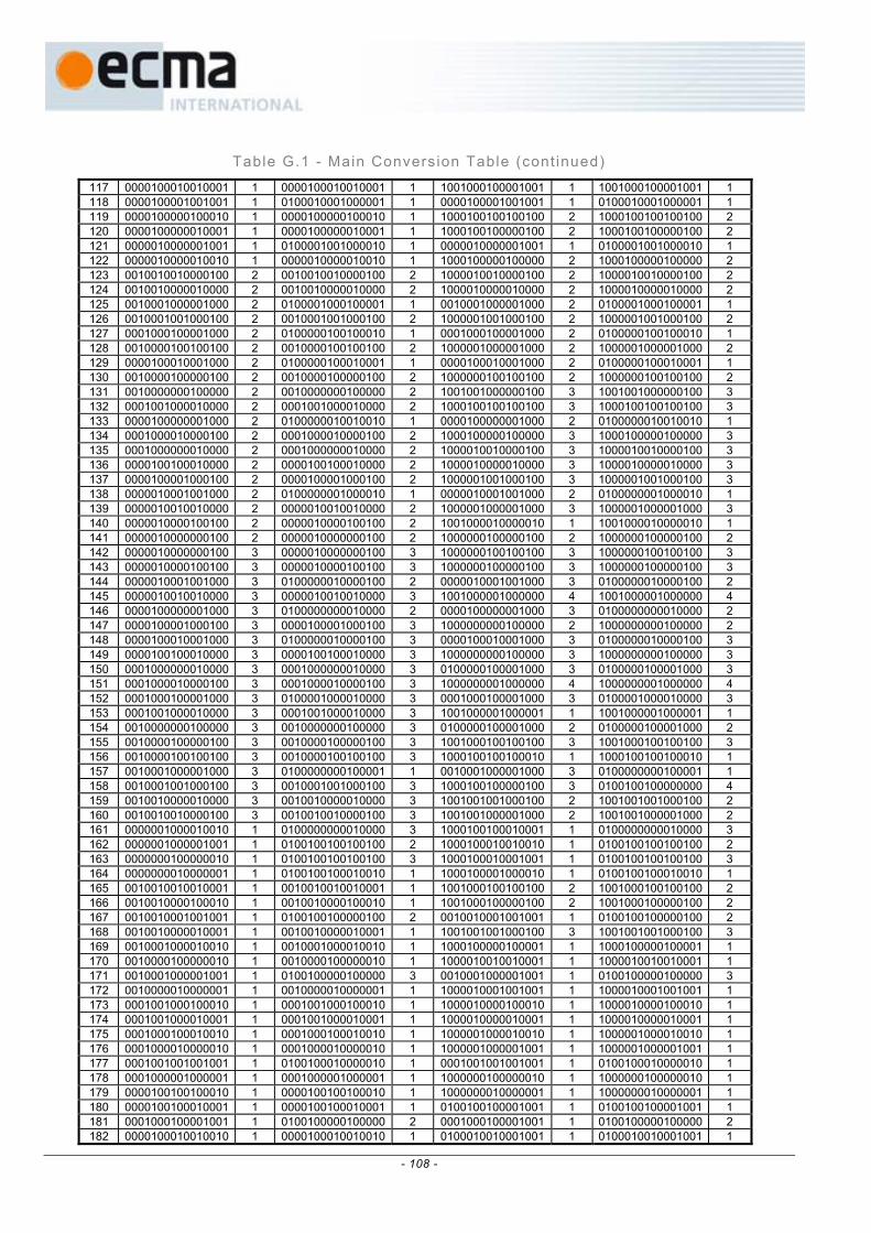
Table G.1 - Main Conversion Table (cont inued)
117 0000100010010001 1 0000100010010001 1 1001000100001001 1 1001000100001001 1 118 0000100001001001 1 0100010001000001 1 0000100001001001 1 0100010001000001 1 119 0000100000100010 1 0000100000100010 1 1000100100100100 2 1000100100100100 2 120 0000100000010001 1 0000100000010001 1 1000100100000100 2 1000100100000100 2 121 0000010000001001 1 0100001001000010 1 0000010000001001 1 0100001001000010 1 122 0000010000010010 1 0000010000010010 1 1000100000100000 2 1000100000100000 2 123 0010010010000100 2 0010010010000100 2 1000010010000100 2 1000010010000100 2 124 0010010000010000 2 0010010000010000 2 1000010000010000 2 1000010000010000 2 125 0010001000001000 2 0100001000100001 1 0010001000001000 2 0100001000100001 1 126 0010001001000100 2 0010001001000100 2 1000001001000100 2 1000001001000100 2
2 0100000100100010 1 0001000100001000 2 0100000100100010 1 128 0010000100100100 2 0010000100100100 2 1000001000001000 2 1000001000001000 2 129 0000100010001000 2 0100000100010001 1 0000100010001000 2 0100000100010001 1 130 0010000100000100 2 0010000100000100 2 1000000100100100 2 1000000100100100 2 131 0010000000100000 2 0010000000100000 2 1001001000000100 3 1001001000000100 3 132 0001001000010000 1000100100100100 2 0001001000010000 2 1000100100100100 3 3 133 0000100000001000 2 0100000010010010 1 0000100000001000 2 0100000010010010 1 134 0001000010000100 2 0001000010000100 2 1000100000100000 3 1000100000100000 3 135 0001000000010000 2 0001000000010000 2 1000010010000100 3 1000010010000100 3 136 0000100100010000 2 0000100100010000 2 1000010000010000 3 1000010000010000 3 137 0000100001000100 2 0000100001000100 2 1000001001000100 3 1000001001000100 3 138 0000010001001000 1 2 0100000001000010 0000010001001000 2 0100000001000010 1
2 0000010010010000 2 1000001000001000 1000001000001000 3 140 0000010000100100 2 0000010000100100 2 1001000010000010 1 1001000010000010 1 141 0000010000000100 2 0000010000000100 2 1000000100000100 2 1000000100000100 2 142 0000010000000100 3 0000010000000100 3 1000000100100100 3 1000000100100100 3 143 0000010000100100 3 0000010000100100 3 1000000100000100 3 1000000100000100 3 144 0000010001001000 3 0100000010000100 2 0000010001001000 3 0100000010000100 2 145 0000010010010000 3 0000010010010000 3 1001000001000000 4 1001000001000000 4 146 0000100000001000 3 0100000000010000 2 0000100000001000 3 0100000000010000 2 147 0000100001000100 3 0000100001000100 3 1000000000100000 2 1000000000100000 2 148 0000100010001000 3 0100000010000100 3 0000100010001000 3 0100000010000100 3 149 0000100100010000 3 0000100100010000 3 1000000000100000 3 1000000000100000 3 150 0001000000010000 3 0001000000010000 3 0100000100001000 3 0100000100001000 3 151 0001000010000100 3 0001000010000100 3 1000000001000000 4 1000000001000000 4 152 0001000100001000 3 0100001000010000 3 0001000100001000 3 0100001000010000 3 153 0001001000010000 3 0001001000010000 3 1001000001000001 1 1001000001000001 1 154 0010000000100000 3 0010000000100000 3 0100000100001000 2 0100000100001000 2 155 0010000100000100 3 0010000100000100 3 1001000100100100 3 1001000100100100 3 156 0010000100100100 3 0010000100100100 3 1000100100100010 1 1000100100100010 1 157 0010001000001000 3 0100000000100001 1 0010001000001000 3 0100000000100001 1 158 0010001001000100 3 0010001001000100 3 1000100100000100 3 0100100100000000 4 159 0010010000010000 3 0010010000010000 3 1001001001000100 2 1001001001000100 2 160 0010010010000100 3 0010010010000100 3 1001001000001000 2 1001001000001000 2 161 0000001000010010 1 0100000000010000 3 1000100100010001 1 0100000000010000 3 162 0000001000001001 1 0100100100100100 2 1000100010010010 1 0100100100100100 2 163 0000000100000010 1 0100100100100100 3 1000100010001001 1 0100100100100100 3 164 0000000010000001 1 0100100100010010 1 1000100001000010 1 0100100100010010 1 165 0010010010010001 1 0010010010010001 1 1001000100100100 2 1001000100100100 2 166 0010010000100010 1 0010010000100010 1 1001000100000100 2 1001000100000100 2 167 0010010001001001 1 0100100100000100 2 0010010001001001 1 0100100100000100 2 168 0010010000010001 1 0010010000010001 1 1001001001000100 3 1001001001000100 3 169 0010001000010010 1 0010001000010010 1 1000100000100001 1 1000100000100001 1 170 0010000100000010 1 0010000100000010 1 1000010010010001 1 1000010010010001 1 171 0010001000001001 1 0100100000100000 3 0010001000001001 1 0100100000100000 3 172 0010000010000001 1 0010000010000001 1 1000010001001001 1 1000010001001001 1 173 0001001000100010 1 0001001000100010 1 1000010000100010 1 1000010000100010 1 174 0001001000010001 1 0001001000010001 1 1000010000010001 1 1000010000010001 1 175 0001000100010010 1 0001000100010010 1 1000001000010010 1 1000001000010010 1 176 0001000010000010 1 0001000010000010 1 1000001000001001 1 1000001000001001 1 177 0001001001001001 1 0100100010000010 1 0001001001001001 1 0100100010000010 1
1 0001000001000001 1 1000000100000010 1 1000000100000010 1 179 0000100100100010 1 0000100100100010 1 1000000010000001 1 1000000010000001 1 180 0000100100010001 1 0000100100010001 1 0100100100001001 1 0100100100001001 1 181 0001000100001001 1 0100100000100000 2 0001000100001001 1 0100100000100000 2 182 0000100010010010 1 0000100010010010 1 0100010010001001 1 0100010010001001 1
127 0001000100001000
139 0000010010010000 3
178 0001000001000001
- 108 -
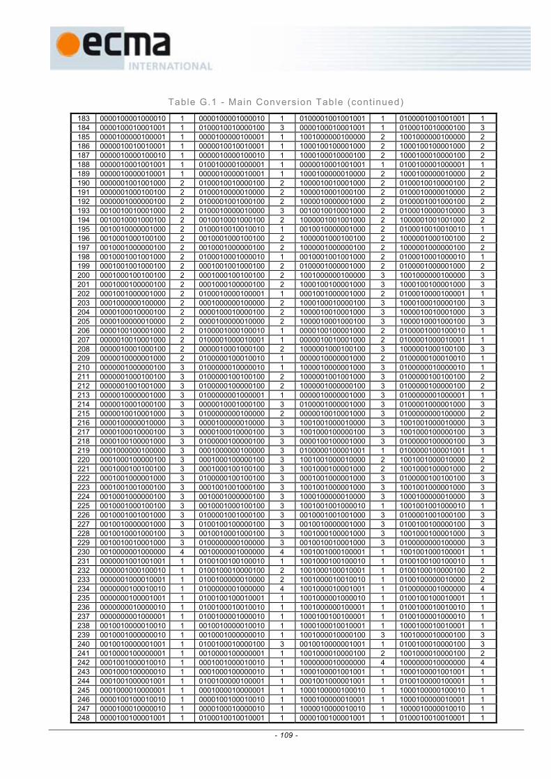
Table G.1 - Main Conversion Table (cont inued)
183 0000100001000010 1 0000100001000010 1 0100001001001001 1 0100001001001001 1 184 0000100010001001 1 0100010010000100 3 0000100010001001 1 0100010010000100 3 185 0000100000100001 1 0000100000100001 1 1001000000100000 2 1001000000100000 2 186 0000010010010001 1 0000010010010001 1 1000100100001000 2 1000100100001000 2 187 0000010000100010 1 0000010000100010 1 1000100010000100 2 1000100010000100 2 188 0000010001001001 1 0100100001000001 1 0000010001001001 1 0100100001000001 1 189 0000010000010001 1 0000010000010001 1 1000100000010000 2 1000100000010000 2 190 0000001001001000 2 0100010010000100 2 1000010010001000 2 0100010010000100 2 191 0000001000100100 2 0100010000010000 2 1000010001000100 2 0100010000010000 2 192 0000001000000100 2 0100001001000100 2 1000010000001000 2 0100001001000100 2 193 0010010010001000 2 0100010000010000 3 0010010010001000 2 0100010000010000 3 194 0010010001000100 2 0010010001000100 2 1000001001001000 2 1000001001001000 2 195 0010010000001000 2 0100010010010010 1 0010010000001000 2 0100010010010010 1
0010001000100100 2 0010001000100100 2 1000001000100100 2 1000001000100100 2 197 0010001000000100 2 0010001000000100 2 1000001000000100 2 1000001000000100 2 198 0010001001001000 2 0100010001000010 1 0010001001001000 2 0100010001000010 1 199 0001001001000100 2 0001001001000100 2 0100001000001000 2 0100001000001000 2 200 0001000100100100 2 0001000100100100 2 1001000000100000 3 1001000000100000 3 201 0001000100000100 2 0001000100000100 2 1000100100001000 3 1000100100001000 3 202 0001001000001000 2 0100010000100001 1 0001001000001000 2 0100010000100001 1 203 0001000000100000 2 0001000000100000 2 1000100010000100 3 1000100010000100 3 204 0000100010000100 2 0000100010000100 2 1000010010001000 3 1000010010001000 3 205 0000100000010000 10000100010001002 0000100000010000 2 1000010001000100 3 3 206 0000100100001000 2 0100001000100010 1 0000100100001000 2 0100001000100010 1
0000010010001000 2 0100001000010001 1 2 0100001000010001208 0000010001000100 2 0000010001000100 2 1000001000100100 3 1000001000100100 3 209 0000010000001000 2 0100000100010010 1 0000010000001000 2 0100000100010010 1 210 0000001000000100 3 0100000010000010 1 1000010000001000 3 0100000010000010 1 211 0000001000100100 3 0100000100100100 2 1000001001001000 3 0100000100100100 2 212 0000001001001000 3 0100000100000100 2 1000001000000100 3 0100000100000100 2 213 0000010000001000 3 0100000001000001 1 0000010000001000 3 0100000001000001 1 214 0000010001000100 3 0000010001000100 3 0100001000001000 3 0100001000001000 3 215 0000010010001000 0100000000100000 2 2 3 0000010010001000 3 0100000000100000216 0000100000010000 3 3 0000100000010000 3 1001001000010000 1001001000010000 3
3 3 1001000100000100 3 1001000100000100 3 218 0000100100001000 3 0100000100000100 3 0000100100001000 3 0100000100000100 3 219 0001000000100000 3 0001000000100000 3 0100000100001001 1 0100000100001001 1 220 0001000100000100 3 0001000100000100 3 1001001000010000 2 1001001000010000 2 221 0001000100100100 3 0001000100100100 3 1001000100001000 2 1001000100001000 2 222 0001001000001000 3 0100000100100100 3 0001001000001000 3 0100000100100100 3 223 0001001001000100 3 0001001001000100 3 1001001000001000 3 1001001000001000 3 224 0010001000000100 3 0010001000000100 3 1000100000010000 3 1000100000010000 3 225 0010001000100100 3 0010001000100100 3 1001001001000010 1 1001001001000010 1 226 0010001001001000 3 0100001001000100 3 0010001001001000 3 0100001001000100 3 227 0010010000001000 3 0100100100000100 3 0010010000001000 3 0100100100000100 3 228 0010010001000100 3 0010010001000100 3 1001000100001000 3 1001000100001000 3 229 0010010010001000 3 0100000000100000 3 0010010010001000 3 0100000000100000 3 230 0010000001000000 4 0010000001000000 4 1001001000100001 1 1001001000100001 1 231 0000001001001001 1 0100100100100010 1 1001000100100010 1 0100100100100010 1 232 0000001000100010 1 0100100010000100 2 1001000100010001 1 0100100010000100 2 233 0000001000010001 1 0100100000010000 2 1001000010010010 1 0100100000010000 2 234 0000000100010010 1 0100000001000000 4 1001000010001001 1 0100000001000000 4 235 0000000100001001 1 0100100100010001 1 1001000001000010 1 0100100100010001 1 236 0000000010000010 1 0100100010010010 1 1001000000100001 1 0100100010010010 1 237 0000000001000001 1 0100100001000010 1 1000100100100001 1 0100100001000010 1 238 0010010000010010 1 0010010000010010 1 1000100010010001 1 1000100010010001 1 239 0010001000000010 1 0010001000000010 1 1001000010000100 3 1001000010000100 3 240 0010010000001001 1 0100100010000100 3 0010010000001001 1 0100100010000100 3 241 0010000100000001 1 0010000100000001 1 1001000010000100 2 1001000010000100 2 242 0001001000010010 1 4 0001001000010010 1 1000000010000000 1000000010000000 4 243 0001000100000010 1 0001000100000010 1 1000100001001001 1 1000100001001001 1 244 0001001000001001 1 0100100000100001 1 0001001000001001 1 0100100000100001 1 245 0001000010000001 1 0001000010000001 1 1000100000100010 1 1000100000100010 1 246 0000100100010010 1 0000100100010010 1 1000100000010001 1 1000100000010001 1 247 0000100010000010 1 0000100010000010 1 1000010000010010 1 1000010000010010 1 248 0000100100001001 1 0100010010010001 1 0000100100001001 1 0100010010010001 1
196
207 0000010010001000 1
217 0000100010000100 0000100010000100
- 109 -

Table G.1 - Main Conversion Table (concluded)
249 0000100001000001 1 0000100001000001 1 1000010000001001 1 1000010000001001 1 250 0000010010010010 1 0000010010010010 1 1000001000000010 1 1000001000000010 1 251 0000010001000010 1 0000010001000010 1 1000000100000001 1 1000000100000001 1 252 0000010010001001 1 0100010000100010 1 0000010010001001 1 0100010000100010 1 253 0000010000100001 1 0000010000100001 1 0100100010001001 1 0100100010001001 1 254 0000001001000100 2 0100010000010001 1 1001000000010000 2 0100010000010001 1 255 0000001000001000 2 0100001000010010 1 1000100100010000 2 0100001000010010 1
- 110 -

Table G.2 – Subst i tut ion Conversion Table
8-bit State 1
State 2
State 3
State 4
byte Code Word Next Code Word Next Code Word Next Code Word Next
msb lsb State msb lsb State msb lsb State msb lsb State 0 0000010010000000 4 0000010010000000 4 0100100001001000 2 0100100001001000 2 1 0000100100000000 4 0000100100000000 4 0100100001001000 3 0100100001001000 3 2 0001001000000000 4 0001001000000000 4 0100100000001001 1 0100100000001001 1 3 0000001001000000 4 0100010000000001 1 1000001000000000 4 0100010000000001 1 4 0000000100100000 3 0100100000000010 1 1001000000000100 3 0100100000000010 1 5 0000000010010000 3 0100001000000000 4 1001000000100100 3 0100001000000000 4 6 0000000001001000 3 0100100000000100 2 1001000001001000 3 0100100000000100 2 7 0000000001001000 2 0100000100000000 4 1001000000000100 2 0100000100000000 4 8 0000000010010000 2 0100100010010000 3 1001000000100100 2 0100100010010000 3 9 0000000100100000 2 0100100000100100 2 1001000001001000 2 0100100000100100 2 10 0000010001000000 4 0000010001000000 4 1001001001000000 4 1001001001000000 4 11 0000100010000000 4 0000100010000000 4 1000100001001000 3 1000100001001000 3 12 0001000100000000 4 0001000100000000 4 0100010001001000 3 0100010001001000 3 13 0010001000000000 4 0010001000000000 4 1000100000000100 3 1000100000000100 3 14 0000001000100000 3 0100100000000100 3 1001000010010000 3 0100100000000100 3 15 0000000100010000 3 0100100010010000 2 1001000100100000 3 0100100010010000 2 16 0000000010001000 3 0100001000000001 1 0100100000001000 3 0100001000000001 1 17 0000000001000100 3 0100010000000010 1 0100100010001000 3 0100010000000010 1 18 0000000001000100 2 0100100000100100 3 1001000010010000 2 0100100000100100 3 19 0000000010001000 2 0100100100100000 3 1001000100100000 2 0100100100100000 3 20 0000000100010000 2 0100100100100000 2 0100010001001000 2 0100100100100000 2 21 0000001000100000 2 0100100000010010 1 0100100000001000 2 0100100000010010 1 22 0000010010000001 1 0000010010000001 1 1000100000100100 3 1000100000100100 3 23 0000100100000001 1 0000100100000001 1 1000100010010000 3 1000100010010000 3 24 0001001000000001 1 0001001000000001 1 0100100010001000 2 0100100010001000 2 25 0010010000000001 1 0010010000000001 1 1000100000000100 2 1000100000000100 2 26 0000000001001001 1 0100010000000100 3 1000010000000001 1 0100010000000100 3 27 0000000010010001 1 0100000100000001 1 1000100000000010 1 0100000100000001 1 28 0000000100100001 1 0100010000000100 2 1001000000001001 1 0100010000000100 2 29 0000001001000001 1 0100001000000010 1 1001000000010010 1 0100001000000010 1 30 0000100001000000 4 0000100001000000 4 1000100000100100 2 1000100000100100 2 31 0001000010000000 4 0001000010000000 4 1000100001001000 2 1000100001001000 2 32 0010000100000000 4 0010000100000000 4 0100010000001001 1 0100010000001001 1 33 0000010000100000 3 0000010000100000 3 0100100001001001 1 0100100001001001 1 34 0000001000010000 3 0100010000010010 1 1000100100100000 3 0100010000010010 1 35 0000000100001000 3 0100100000010001 1 1001000000001000 3 0100100000010001 1 36 0000000010000100 3 0100000010000000 4 1001000001000100 3 0100000010000000 4 37 0000010000100000 2 0000010000100000 2 1000001000000001 1 1000001000000001 1 38 0000000010000100 2 0100010000100100 3 1000100010010000 2 0100010000100100 3 39 0000000100001000 2 0100010000100100 2 1000100100100000 2 0100010000100100 2 40 0000001000010000 2 0100100000100010 1 1001000000001000 2 0100100000100010 1 41 0000010001000001 1 0000010001000001 1 1000010000000010 1 1000010000000010 1 42 0000010010000010 1 0000010010000010 1 1000000100000000 4 1000000100000000 4 43 0000100010000001 1 0000100010000001 1 1001000001000100 2 1001000001000100 2 44 0000100100000010 1 0000100100000010 1 1000100000001001 1 1000100000001001 1 45 0001000100000001 1 0001000100000001 1 1001000010001000 3 1001000010001000 3 46 0001001000000010 1 0001001000000010 1 1001000100010000 3 1001000100010000 3 47 0010001000000001 1 0010001000000001 1 1000100000010010 1 1000100000010010 1 48 0010010000000010 1 0010010000000010 1 0100010000001000 3 0100010000001000 3 49 0000000001000010 1 0100100010010001 1 1001000000010001 1 0100100010010001 1 50 0000000010001001 1 0100100001000100 3 1001000000100010 1 0100100001000100 3 51 0000000010010010 1 0100010010010000 3 1001000001001001 1 0100010010010000 3 52 0000000100010001 1 0100010010010000 2 1001000010010001 1 0100010010010000 2 53 0000000100100010 1 0100100001000100 2 1001000100100001 1 0100100001000100 2 54 0000001000100001 1 0100100100100001 1 1001001001000001 1 0100100100100001 1 55 0000001001000010 1 0100100100010000 3 0100001000001001 1 0100100100010000 3 56 0001000001000000 4 0001000001000000 4 1001001000100000 3 1001001000100000 3 57 0010000010000000 4 0010000010000000 4 1001000010001000 2 1001000010001000 2 58 0010010010010000 3 0010010010010000 3 1001000100010000 2 1001000100010000 2 59 0010010001001000 3 0100100100010000 2 0010010001001000 3 0100100100010000 2 60 0010010000100100 3 0010010000100100 3 1001001000100000 2 1001001000100000 2 61 0010010000000100 3 0010010000000100 3 0100001001001000 2 0100001001001000 2
- 111 -

Table G.2 - Subst i tut ion Conversion Table (concluded) 62 0001001001001000 3 0100000010000001 1 0001001001001000 3 0100000010000001 1 63 0001001000100100 3 0001001000100100 3 0100001001001000 3 0100001001001000 3 64 0001001000000100 3 0001001000000100 3 0100010010001000 3 0100010010001000 3 65 0000100100100100 3 0000100100100100 3 0100100100001000 3 0100100100001000 3 66 0000100100000100 3 0000100100000100 3 1000010000000100 3 1000010000000100 3 67 0000100000100000 3 0000100000100000 3 1000010000100100 3 1000010000100100 3 68 0000010010000100 3 0000010010000100 3 1000010001001000 3 1000010001001000 3 69 0000010000010000 3 0000010000010000 3 1000010010010000 3 1000010010010000 3 70 0000001001000100 3 0100001000000100 2 1000100000001000 3 0100001000000100 2 71 3 0100100000010000 3 1000100010001000 3 0100100000010000 3 72 0000000100100100 3 0100010001000100 3 1000100100010000 3 0100010001000100 3 73 0000000100000100 3 0100001000100100 3 1001000000010000 3 0100001000100100 3 74 0000010000010000 2 0000010000010000 2 1000100001000100 3 1000100001000100 3 75 0001001001001000 2 0100001000000100 3 0001001001001000 2 0100001000000100 3 76 0000010010000100 2 0000010010000100 2 0100010000001000 2 0100010000001000 2 77 0000100000100000 2 0000100000100000 2 0100010010001000 2 0100010010001000 2 78 0010010001001000 2 0100000100000010 1 0010010001001000 2 0100000100000010 1 79 0000100100000100 2 0000100100000100 2 0100100100001000 2 0100100100001000 2 80 0000100100100100 2 0000100100100100 2 1000010000000100 2 1000010000000100 2 81 0001001000000100 2 0001001000000100 2 1000010000100100 2 1000010000100100 2 82 0001001000100100 2 0001001000100100 2 1000010001001000 2 1000010001001000 2 83 0010010000000100 2 0010010000000100 2 1000010010010000 2 1000010010010000 2 84 0010010000100100 2 0010010000100100 2 1000100000001000 2 1000100000001000 2 85 0010010010010000 2 0010010010010000 2 0100010001001001 1 0100010001001001 1 86 0000000100000100 2 0100001000100100 2 1000100001000100 2 0100001000100100 2 87 0000000100100100 2 0100010001000100 2 1000100010001000 2 0100010001000100 2
0000001000001000
- 112 -

Annex H (normative)
Optimum Power Control and Recording Conditions
H.1 Optimum writing power The optimum recording power Pwo that should be used for recording a disk is dependent on the disk, the recorder and the recording speed.
For the disk there are three main parameters involved: − The sensitivity of the recording layers to laser power at a given wavelength. − The change in sensitivity when the laser wavelength is changed. − The “pit-formation mechanism” in the recording layer, which is dependent on the applied layer
technology.
For the recorder the three main parameters involved are: − The dimensions and optical quality of the laser light spot at the recording layer. − The applied write strategy. − The actual wavelength of the laser when recording the disk (see Annex J).
This wavelength depends on e.g.: − the type of laser, − the spread in wavelength for each individual laser of this type (and so for each individual
recorder), − the actual write power, − the temperature of the laser.
As the optimum writing power Pwo depends on the disk, the recorder and the recording speed that are actually used, this power should be determined for each recorder/disk combination at the actual recording speed. Such a determination of the actual optimum writing power Pwo is called an Optimum Power Control procedure (OPC procedure).
H.1.1 Asymmetry and optimum writing power For different writing powers, the asymmetry of the recorded 8-to-16 modulated data is different.
By test recording random 8-to-16 modulated data with different writing powers, and measuring the resulting asymmetry in the HF signal, the optimum writing power for the specific combination of disk and recorder at a specific recording speed can be obtained.
Figure H.1 shows schematically the procedure with the OPC and write strategy. The main signals that are influenced by the applied write strategy and power level are the modulation, the asymmetry and the jitter. In practice the asymmetry appears to be a sensitive parameter for OPC. An easier to handle alternative for the asymmetry is β.
- 113 -

target βOPC
Pwrite
Pwrite
writestrategy
discmodasym ( )jitter
β
real (β ≡ asymmetry)
write pulsetrain
P &write st rategyparameters
IND
HF
Figure H.1 - Schematical diagram of OPC procedure
H.1.2 Measurement of asymmetry by means of β Using the definition of asymmetry directly, may result in complicated recorder electronics. Therefore a different parameter is used as a representation of asymmetry. This parameter β is based on using the AC coupled HF signal before equalization.
By definition: β = (A1 + A2)/(A1 - A2) as the difference between the peak levels A1 and A2 (A1+A2), normalized to the peak-peak value (A1-A2) of the HF signal. See Figure H.2.
β defined in this way, will be approximately equal to the asymmetry.
Zero asymmetry of the measured HF signal will, in general, correspond to β ≈ 0.
A1
A2
A1
A2
A1
A2
land-level
pit-level
0
HF-
sign
al
P < Pwo P ≈ Pwo P > Pwo
Figure H.2 - AC-coupled HF signals recorded with different writing powers
- 114 -

H.2 The OPC procedure To facilitate the OPC procedure, an indicative value (an estimation) for the writing power is given at several writing speeds (see 14.4.2).
These values can not be used as the exact optimum writing power for the actual disk/recorder/speed combination, but can be used as a starting value for an OPC procedure.
As the setpoint in the OPC procedure, the target β value indicated in 14.4.2 is used.
The OPC procedure must be performed in an area on the disk that is specially reserved for this purpose: the Inner or Outer Disk Test Zone (see Table 6).
H.3 Write strategy parameters at other speeds It is recommended that +R recorders compliant with this document use the indicated test speeds as follows:
− the Primary recording velocity indicates the lowest speed at which the disk has been verified for a specific write strategy,
− the Upper recording velocity indicates the highest speed at which the disk has been verified for a specific write strategy,
an estimate for the write parameters at any intermediate speed can be determined by linear interpolation between the parameters at the Primary recording velocity and the Upper recording velocity as indicated in 14.4.2. NOTE Disk Manufacturers should design media with a reasonable “linear” behaviour of the write strategy parameters over the speed range indicated in 14.4.2.
H.4 Media margins at non-optimum write power To create some margins for practical accuracy requirements for drive implementations, the disk should allow for some deviations of the write power from the optimum values. Therefore the following specifications should be fulfilled (strongly recommended):
For actual write powers Pw in the range 0,90×Pwo to 1,05×Pwo, and Pb = Pbo, the disk is recordable within all specifications.
- 115 -

- 116 -

Annex I (informative)
Light fastness of the disk
Light fastness of the +R disk should be tested with an air cooled Xenon lamp and test apparatus complying with ISO-105-B02.
Test conditions:
Black Panel Temperature : < 40 °C •
•
•
•
Relative humidity: : 70 - 80 %
Disk illumination:
Through the substrate, normal incident.
Disk not packed, out of cassette.
Requirement: All disk specifications must be fulfilled, after illumination with a Xenon lamp corresponding with the European Wool Reference #5 (see ISO-105-B02).
Remark:
The change in color of the +R disk is irrelevant for this test.
- 117 -

- 118 -
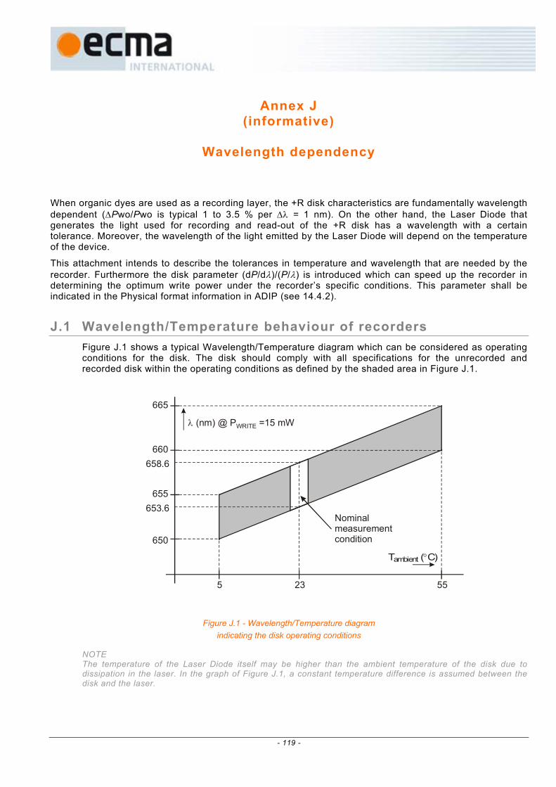
Annex J (informative)
Wavelength dependency
When organic dyes are used as a recording layer, the +R disk characteristics are fundamentally wavelength dependent (∆Pwo/Pwo is typical 1 to 3.5 % per ∆λ = 1 nm). On the other hand, the Laser Diode that generates the light used for recording and read-out of the +R disk has a wavelength with a certain tolerance. Moreover, the wavelength of the light emitted by the Laser Diode will depend on the temperature of the device.
This attachment intends to describe the tolerances in temperature and wavelength that are needed by the recorder. Furthermore the disk parameter (dP/dλ)/(P/λ) is introduced which can speed up the recorder in determining the optimum write power under the recorder’s specific conditions. This parameter shall be indicated in the Physical format information in ADIP (see 14.4.2).
J.1 Wavelength/Temperature behaviour of recorders Figure J.1 shows a typical Wavelength/Temperature diagram which can be considered as operating conditions for the disk. The disk should comply with all specifications for the unrecorded and recorded disk within the operating conditions as defined by the shaded area in Figure J.1.
T ( C)ambient °
λ (nm) @ P =15 mWWRITE
5 23
665
655
660658.6
653.6
650
55
Nominalmeasurementcondition
Figure J.1 - Wavelength/Temperature diagram indicating the disk operating conditions
NOTE The temperature of the Laser Diode itself may be higher than the ambient temperature of the disk due to dissipation in the laser. In the graph of Figure J.1, a constant temperature difference is assumed between the disk and the laser.
- 119 -

J.2 Write power / Wavelength dependency of the disk In practice it is not easy to determine the write power dependency of the disk on the laser wavelength directly. What can be measured by using usual optical equipment is the absorption of the recording layer as a function of the wavelength. When assuming that the write power is inversely proportional to the absorption of the recording layer, the dependency of this absorption on the wavelength can be translated into a dependency of the write power on the wavelength.
J.2.1 Measurement of the absorption of the recording layer of the disk The absorption of the recording (dye) layer of the disk is determined by measuring the reflection and transmission versus the wavelength. For this purpose a parallel beam is used at a small angle to the normal on the disk surface. The wavelength is controlled by means of a monochromator.
The measurements are performed on a mirror area at the inner side of the disk in order to prevent wavelength dependent diffraction of the light caused by grooved areas.
frontsurface
dyelayersubstrate
rs
rs
ts R A T1
(1-r ) .t .Rs s2 2
(1-r ).t .Ts s
r .(1-r ) .t .Rs s s2 4 2
r .(1-r ).t .R.Ts s s3
rsi-1.(1-r ) .t .Rs s
2 2i i r .Tsj-1.(1-r ).t .Rs s
2j-1 j-1
R//T//
Figure J.2 – Definitions of reflectivity, transmission and absorption
In Figure J.2 the following applies:
for the transparency of the formulas, the intensity of the incident beam is assumed to be normalized to 1
rs = reflectivity of the entrance surface
ts = transmission of the substrate
R = reflectivity of the recording layer
A = absorption of the recording layer
T = transmission of the recording layer
R// = total measured reflected light
T// = total measured transmitted light
- 120 -

From: ( )( ).R.tr1
.R.tr1r 2ss
2s
2s
s//−
−+=R
the reflectivity of the dye can be calculated: ( ) 2
ss//s
s//
.t2.r.Rr1rR
−+
−=R
and from: ( ).R.tr1.T.tr1T 2
ss
ss//
−
−= it follows that ( ) ss
2ss
// .tr1.R.tr1.TT
−−
=
Because A+T+R=1, the absorption of the dye layer is given by: A=1-R-T
J.2.2 Determination of parameters for the Physical format information in ADIP
0,22
0,20
0,18
0,16
12,5
11,25
10
8,75
A
Pp(mW)
PIND
λIND
λref wavelength (nm)650 655 660 665
measuredabsorption curve
calculatedpower curve
measured calibration point
Figure J.3 – Example of absorption and power versus wavelength
The absorbed power Px = Pw (λ) × A(λ) is creating the marks in the recording layer. It is assumed that this power Px is more or less independent on the wavelength. In this case, Pw (λ), a function of the wavelength λ, can be determined from A(λ) with the help of the following formula:
)A(
)A()w()w( refrefλ
λ λ×λ=
PP , in which Pw (λref) is the measured write power at λref.
The parameter n = (dPw/dλ)/(PIND/λIND) to be recorded in the Physical format information in ADIP can be determined from the power curve. dPw/dλ shall be averaged over the wavelength range from 645 nm to 670 nm. λIND has been chosen to be 655 nm and PIND shall be Pw (λIND) as determined from the calculated power curve. The parameter (dPw/dλ)/(PIND/λIND) is in principal speed independent.
- 121 -

J.2.3 Determination of start power for the OPC procedure in a specific recorder The corrected power indication Pcor at the actual wavelength of the recorder λactual can be approximated by:
)(d
wdP)( INDactualINDactualcor λ−λ×λ
+=λPP ,
in which as well PIND as dPw/dλ are speed dependent.
The value of dPw/dλ at a speed v1 can be calculated from the values specified in ADIP:
v1atINDINDv1at
Pd
wd×
λ=
λ
nP
The optimum start value of the power for the OPC procedure at a speed v1 can now be determined by the following formula:
)(P
P)(P INDactualIND
v1atINDv1atINDactualv1atstart λ−λ×
λ
×+=λ
n
- 122 -

Annex K (informative)
Running OPC
The correct writing power for the +R disk is to be determined by means of an Optimum Power Calibration procedure as described in Annex H of this document. However, after this calibration, the optimum power may change because of:
− power sensitivity fluctuation over the disk,
− wavelength shift of the laser diode due to change in operating temperature,
− change of spot aberrations due to change in disk skew, substrate thickness, defocus, etc.,
− changed conditions of disk and/or optics, when OPC was carried out a long time before actual recording.
The purpose of a Running OPC is to actively monitor the mark formation process and continuously adjust the writing power to the optimum power that is required. During the OPC procedure, also a “Running OPC signal” may be obtained that can be associated with optimally written marks (for example using the instantaneously reflected light signal). Such a “Running OPC signal” can be used to maintain subsequent recordings at the same optimal level as that determined by the OPC procedure.
- 123 -

- 124 -

Annex L (informative)
Transportation
L.1 General As transportation occurs under a wide range of temperature and humidity variations, for differing periods, by many methods of transport and in all parts of the world, it is not practical to specify mandatory conditions for transportation or for packaging.
L.2 Packaging The form of packaging should be agreed between sender and recipient or, in absence of such an agreement, is the responsibility of the sender. It should take into account the following hazards.
L.2.1 Temperature and humidity Insulation and wrapping should be designed to maintain the conditions for storage over the estimated period of transportation.
L.2.2 Impact loads and vibrations a) Avoid mechanical loads that would distort the shape of the disk.
b) Avoid dropping the disk.
c) Disks should be packed in a rigid box containing adequate shock-absorbent material.
d) The final box should have a clean interior and a construction that provides sealing to prevent the ingress of dirt and moisture.
- 125 -

- 126 -

Annex M (informative)
Measurement of the groove wobble amplitude
M.1 Relation between wobble signal and wobble amplitude The wobble amplitude in nm cannot easily be measured directly. However, it can be derived from the normalized wobble signal. The theoretical results for such a derivation are given below.
The peak value of the wobble signal IW can be seen as:
IWp = A × sin( 2 × π × a / p)
where:
a = wobble amplitude in nm
p = track pitch of the radial error signal
A = the peak value of the radial error signal
In Figure M.1 the parameters a, p, A and IWp are shown. The groove has a peak displacement of 'a' (wobble amplitude) from the averaged centre of the groove to the actual centre of the groove. The normalized wobble signal can now be defined as:
( )
×π×=
×
×=
− p2sin
A22 Wp
pp21
Wpp aIII
I
where
(I1 - I2)pp = 2 × A
The wobble signal IW is not only dependent on the wobble amplitude a, but also the track pitch p. Due to normalization, dependencies on groove geometry, spot shape and optical aberrations have been eliminated.
M.2 Tolerances of the normalized wobble signal From the above formulae for the normalized wobble signal, the tolerances as given in 28.4 can be converted to nm for a given track pitch of 'p' = 0,74 µm.
Lower limit: 0,15 corresponds to a = 18 nm. Upper limit: 0,25 corresponds to a = 30 nm.
- 127 -
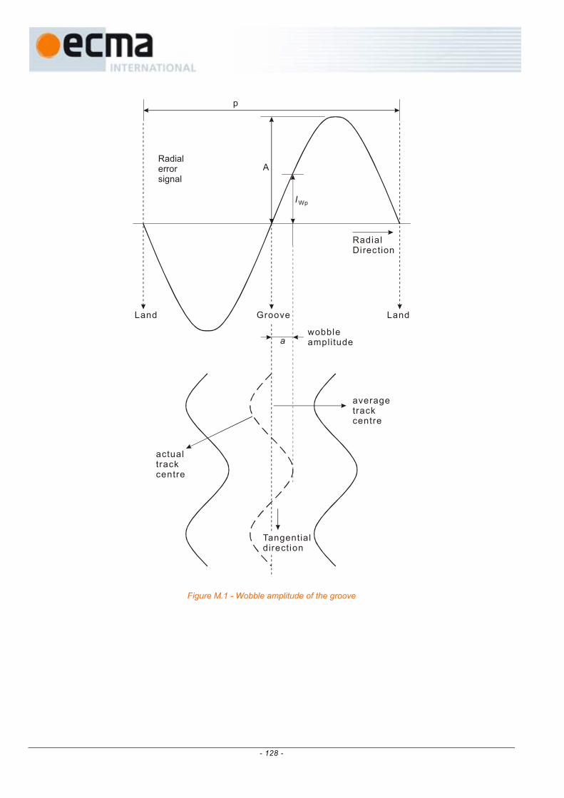
A
p
IWp
Land Groove Land
RadialDirection
a
averagetrackcentre
actualtrackcentre
wobbleamplitude
Tangentialdirection
Radialerrorsignal
Figure M.1 - Wobble amplitude of the groove
- 128 -

Annex N (informative)
How to use the Physical format information in ADIP
To fully exploit the Physical format information in the ADIP, the following rules are given as a recommended guideline (see also the flowchart in Figure N.1).
Drives should read the ADIP and check for the following information: 1) check the Disk Category in byte 0
⇒ determine if the disk is a +R or +RW disk; use the related book for further interpretations.
Drives shall respect the Disk Application Code: 2) check the Disk Application Code in byte 17
⇒ if the drive is not able to obey the rules related to a specific Disk Application Code, the drive shall block the disk for recording.
If the drive can do "media recognition" (i.e. the drive can uniquely determine the manufacturer and the type of the disk and has optimum sets of write parameters for certain disks in its memory):
3) check for Disk Manufacturer and Media type ID (bytes 19 to 29)
⇒ choose the optimum write strategy for this specific media from the drive’s memory.
If the drive fails to recognize the media: 4) check the version number in byte 0
⇒ if the version number is unknown: do not use the contents of bytes 32 to 63,
⇒ if the version number is known: interpret bytes 32 to 63 according to the correct book version.
5) check byte 18 for the presence of Extended Information blocks
⇒ if no EI blocks are present: only basic write strategy is available.
If EI blocks present: 6) check the format number in each present EI block
⇒ if the format number is unknown: do not use the contents of the related EI block,
⇒ if the format number is known: interpret the EI block according to the correct book version.
Now the drive can choose the best fitting recording speed and write strategy from the available options:
⇒ basic write strategy (1x ~ 2,4x) as defined in bytes 32 to 63,
⇒ write strategy from one of the known EI blocks,
⇒ for each available write strategy the drive should check the actually supported recording speeds indicated in the related bytes (supported recording speeds can be adapted in future versions of this document).
- 129 -
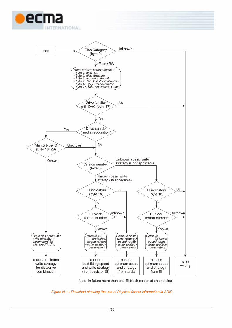
Disc Category(byte 0)
Drive can do“media recognition”
Drive familiarwith DAC (byte 17)
Version number(byte 0)
EI indicators(byte 18)
EI blockformat number
EI blockformat number
EI indicators(byte 18)
Man.& type ID(byte 19~29)
start
stopwriting
Unknown
+R or +RW
Yes
Yes
No
No
Unknown
Unknown (basic writestrategy is not applicable)
UnknownUnknown
Known
Known (basic writestrategy is applicable)
Known Known
00 00
n n
chooseoptimum speed
and strategyfrom EI
chooseoptimum speed
and strategyfrom basic
choosebest fitting speedand write strategy(from basic or EI)
choose optimumwrite strategyfor disc/combination
drive
Note: in future more than one EI block can exist on one disc!
Retrieve basicwrite strategy:- speed range- write strategy parameters
Retrieve EI block:- speed range- write strategy parameters
Retrieve all strategies:- speed ranges - write strategy parameters
Drive has optimumwrite strategyparameters forthis specific disc
Retrieve disc characteristics:- byte 1: disc size- byte 2: disc structure- byte 3: recording density- byte 4~15: Data Zone allocation- byte 16: (N)BCA descriptor- byte 17: Disc Application Code
Figure N.1 - Flowchart showing the use of Physical format information in ADIP
- 130 -

Annex O (informative)
Values to be Implemented in Existing and Future Specifications
The values for bytes which this Ecma Standard specifies are related to Recordable disks which are in conformance with this Ecma Standard, viz. +R Format disks. It is expected that other categories of disks will be standardized in future. It is therefore recommended that the following values be used for these other disks. Further possible bit patterns are intended for future standardization.
All standards are subject to revisions, so the information in this Annex can be subject to changes. Therefore it is recommended to check this information against the most recent edition of the indicated standards.
Identification Data Bit b31 shall be set to
ZERO, indicating CLD format ONE, indicating Zoned format
Bit b30 shall be set to
ZERO, indicating pit tracking ONE, indicating groove tracking
Bit b29 shall be set to
ZERO if the reflectivity is greater than 40 % with a PBS optical system ONE if the reflectivity is less than 40 % max. with a PBS optical system
Bit b28 Reserved, shall be set to ZERO
Bits b27 to b26 shall be set to
ZERO ZERO in the Data Zone ZERO ONE in the Lead-in Zone ONE ZERO in the Lead-out Zone ONE ONE in the Middle Zone
Bit b25 shall be set to
ZERO, indicating read-only data ONE, indicating other than read-only data
Bit b24 shall be set to
ZERO on Layer 0 of DL disks, One on Layer 1 of DL disks, ZERO on SL disks.
Bits b23 to b0 shall specify the Physical Sector Number
Physical format information in the ADIP in the Lead-in Zone
Byte 0 - Disk Category and Version Number Bits b7 to b4 shall specify the Disk Category
if set to 0000, they indicate a DVD - Read-Only disk if set to 0001, they indicate a DVD Rewritable disk (DVD-RAM) if set to 0010, they indicate a DVD-Recordable disk (DVD-R)
- 131 -

if set to 0011, they indicate a DVD Re-recordable disk (DVD-RW) if set to 1001, they indicate a +RW disk if set to 1010, they indicate a +R disk
Bits b3 to b0 shall specify the Version Number. Together with b7 to b4 they specify the related document.
if b7 to b4 set to 0000 and b3 to b0 set to 0001, they specify ECMA Standard 267/268 if b7 to b4 set to 0001 and b3 to b0 set to 0001, they specify ECMA Standard 272 if b7 to b4 set to 0001 and b3 to b0 set to 0110, they specify ECMA Standard 330 if b7 to b4 set to 0010 and b3 to b0 set to 0001, they specify ECMA Standard 279 if b7 to b4 set to 0011 and b3 to b0 set to 0010, they specify ECMA Standard 338 if b7 to b4 set to 1001 and b3 to b0 set to 0001, they specify ECMA Standard 274 if b7 to b4 set to 1001 and b3 to b0 set to 0010, they specify ECMA Standard 337 if b7 to b4 set to 1010 and b3 to b0 set to 0001, they specify this document
Byte 1 - Disk size and maximum transfer rate Bits b7 to b4 shall specify the disk size
if set to 0000, they specify a 120 mm disk if set to 0001, they specify an 80 mm disk
Bits b3 to b0 shall specify the maximum transfer rate
if set to 0000, they specify a maximum transfer rate of 2,52 Mbits/s if set to 0001, they specify a maximum transfer rate of 5,04 Mbits/s if set to 0010, they specify a maximum transfer rate of 10,08 Mbits/s if set to 1111, they specify no maximum transfer rate is specified.
Byte 2 - Disk structure Bit b7 shall be set to ZERO.
Bits b6 and b5 shall specify the disk Type
if set to 00, they specify a single recording layer per side if set to 01, they specify two recording layers per side
Bit b4 shall be set to ZERO
Bits b3 to b0 specify the layer type
Bit b3 shall be set to ZERO
Bit b2 if set to ZERO, shall specify that the disk does not contain re-writable Data Zones ONE, shall specify that the disk contains re-writable Data Zones
Bit b1 if set to ZERO, shall specify that the disk does not contain recordable Data Zones ONE, shall specify that the disk contains recordable Data Zones
Bit b0 if set to ZERO, shall specify that the disk does not contain embossed Data Zones ONE, shall specify that the disk contains embossed Data Zones
Byte 3 - Recording density Bits b7 to b4 shall specify the average Channel bit length
if set to 0000, they specify 0,133 µm if set to 0001, they specify 0,147 µm if set to 0010, they indicate that this average length is in the range 0,205 µm to 0,218 µm if set to 1000, they specify 0,176 37 µm
Bits b3 to b0 shall specify the average track pitch
if set to 0000, they indicate a track pitch of 0,74 µm if set to 0001, they indicate a track pitch of 0,80 µm
- 132 -