Embed Size (px)
Citation preview

Standard ECMA-2782 n d Edi t ion - June 2000
S t a n d a r d i s i n g I n f o r m a t i o n a n d C o m m u n i c a t i o n S y s t e m s
Phone: +41 22 849 .60 .00 - Fax: +41 22 849 .60 .01 - URL: h t tp : / /www.ecma.ch - In ternet : he [email protected]
Data Interchange on 12,7 mm128-Track Magnetic TapeCartridge - Parallel SerpentineFormat

.

Standard ECMA-278June 2000
S t a n d a r d i s i n g I n f o r m a t i o n a n d C o m m u n i c a t i o n S y s t e m s
Phone: +41 22 849 .60 .00 - Fax: +41 22 849 .60 .01 - URL: h t tp : / /www.ecma.ch - In ternet : he [email protected]
File: ECMA-278.DOC
Data Interchange on 12,7 mm128-Track Magnetic TapeCartridge - Parallel SerpentineFormat

.
Brief History
Technical Committee ECMA TC17 has produced a series of ECMA Standards for magnetic tapes and magnetic tape cartridgescontaining tapes of different widths, e.g. 12,7 mm, 8 mm, 6,35 mm and 3,81 mm, almost all of which have been adopted byISO/IEC under the fast-track procedure as ECMA Standards. The series of such cartridges with a magnetic tape of 12,7 mmwidth and longitudinally recorded tracks comprises the following standards.
ECMA-120 Data Interchange on 12,7 mm 18-Track Magnetic Tape CartridgeISO/IEC 9661ECMA-152 Data Interchange on 12,7 mm 18-Track Magnetic Tape Cartridge - Extended FormatISO/IEC 11559ECMA-182 Data Interchange on 12,7 mm 48-Track Magnetic Tape Cartridge - DLT 1 FormatISO/IEC 13421ECMA-196 Data Interchange on 12,7 mm 36-Track Magnetic Tape CartridgeISO/IEC 14251ECMA-197 Data Interchange on 12,7 mm 112-Track Magnetic Tape Cartridge - DLT 2 FormatISO/IEC 13962ECMA-209 Data Interchange on 12,7 mm 128-Track Magnetic Tape Cartridge - DLT 3 FormatISO/IEC 14833ECMA-231 Data Interchange on 12,7 mm 128-Track Magnetic Tape Cartridge - DLT 4 FormatISO/IEC 15307ECMA-258 Data Interchange on 12,7 mm 128-Track Magnetic Tape Cartridges - DLT 3-XT FormatISO/IEC 15895ECMA-259 Data Interchange on 12,7 mm 208-Track Magnetic Tape Cartridges - DLT 5 FormatISO/IEC 15896
This Standard ECMA-278 describes a cartridge containing a magnetic tape 12,7 mm wide and a recording format with animproved magnetic medium, 128 longitudinally recorded tracks, and a linear recording density of 3 400 bpmm. With a tape of320 m, this format provides a native storage capacity of 10 Gbytes for user data, or with compressed data of typically26 Gbytes.
This ECMA Standard has been adopted as 2nd Edition of ECMA-278 by the ECMA General Assembly of June 2000.

.

- i -
Table of Contents
Section 1 - General 1
1 Scope 1
2 Conformance 1
2.1 Magnetic tape cartridge 12.2 Generating system 12.3 Receiving system 1
3 References 1
4 Definitions 1
4.1 algorithm 14.2 anhysteretic erase 14.3 average signal amplitude 14.4 azimuth 24.5 back surface 24.6 beginning of partition (BOP) 24.7 beginning of tape (BOT) 24.8 cartridge 24.9 cyclic redundancy check (CRC) character 24.10 end of tape (EOT 24.11 error-correcting code (ECC) 24.12 error-detecting code (EDC) 24.13 File Mark 24.14 flux transition position 24.15 flux transition spacing 24.16 half-wrap 24.17 logical block 24.18 logical forward 24.19 logical reverse 24.20 magnetic tape 24.21 mark tach count 24.22 Master Standard Reference Tape 34.23 physical recording density 34.24 pre-record condition 34.25 recorded element 34.26 Reference Field 34.27 resync character 34.28 SDM set 34.29 Secondary Standard Reference Tape (SSRT) 34.30 servo track 34.31 Standard Reference Amplitude (SRA) 34.32 Standard Reference Current (Ir) 34.33 Test Recording Current (Im ) 34.34 track 34.35 track group 34.36 trailer 44.37 Typical Field 44.38 write equalisation 4

- i i -
5 Conventions and notations 4
5.1 Representation of numbers 45.2 Dimensions 45.3 Names 45.4 Acronyms 4
6 Environment and safety 5
6.1 Cartridge and tape testing environment. 56.2 Cartridge operating environment 56.3 Cartridge storage environment 56.4 Safety 5
6.4.1 Safeness 56.4.2 Flammability 5
6.5 Transportation 6
Section 2 - Requirements for the unrecorded tape 6
7 Mechanical and electrical requirements 6
7.1 Material 67.2 Tape length 67.3 Width 67.4 Total thickness 67.5 Base material thickness 67.6 Discontinuity 67.7 Longitudinal curvature 6
7.7.1 Requirement 67.7.2 Procedure 6
7.8 Out-of-Plane distortions 6
7.9 Cupping 6
7.9.1 Requirement 67.9.2 Procedure 6
7.10 Coefficient of dynamic friction 7
7.10.1 Requirements 77.10.2 Procedure 7
7.11 Coating adhesion 7
7.12 Layer-to-layer adhesion 8
7.12.1 Requirements 87.12.2 Procedure 8
7.13 Electrical resistance 9
7.13.1 Requirement 97.13.2 Procedure 9
7.14 Abrasivity 107.15 Friction characteristics after stress 10
7.15.1 Requirements 107.15.2 Procedure 10
7.16 Surface roughness 10
7.16.1 Requirement 107.16.2 Procedure 11
7.17 Inhibitor tape 11
- i i i -
8 Magnetic recording characteristics 11
8.1 Typical Field 118.2 Signal amplitude 118.3 Resolution 118.4 Broad-band signal-to-noise ratio (BBSNR) 11
8.4.1 Requirement 118.4.2 Procedure 12
9 Tape quality 12
9.1 Missing pulse 12
9.1.1 Requirement 129.1.2 Procedure 12
9.2 Coincident missing pulse 13
9.2.1 Requirement 139.2.2 Procedure 13
9.3 Missing pulse density 13
9.3.1 Requirement 139.3.2 Procedure 13
9.4 Tape durability 13
Section 3 - Mechanical specifications of the tape cartridge 13
10 General 13
10.1 Overall dimensions 1410.2 Write-inhibit mechanism 1410.3 Label areas of the rear side 1510.4 Label area on the top side 1510.5 Case opening 1510.6 Locating notches 1610.7 Locating areas (figure 8) 1610.8 Inside configuration of the case around the case opening 1610.9 Other external dimensions of the case 1610.10 Central window 1710.11 Stacking ribs 1710.12 Recessed area 1710.13 Flexibility of the case 17
10.13.1 Requirements 1710.13.2 Procedure 18
10.14 Tape reel 18
10.14.1 Locking mechanism 1810.14.2 Axis of rotation of the reel 1810.14.3 Metallic insert 1810.14.4 Toothed rim 1810.14.5 Hub of the reel 1910.14.6 Relative positions 1910.14.7 Characteristics of the toothed rim 20
10.15 Leader block 2010.16 Attachment of the tape to the leader block 2110.17 Latching mechanism 2110.18 Tape wind 2110.19 Wind tension 2110.20 Circumference of the tape reel 21
- iv -
10.21 Moment of inertia 2210.22 Material 2210.23 Cartridge identification notches 2210.24 Finger slot 22
Section 4 - Requirements for an interchanged tape 32
11 Method of recording 32
11.1 Physical recording density 3211.2 Bit cell length 3211.3 Average bit cell length 32
11.3.1 Long-term average RLL bit cell length 3211.3.2 Short-term average RLL bit cell length 32
11.4 Rate of change of the short-term average RLL bit cell length 3211.5 Bit shift 3211.6 Total character skew 3311.7 Missing zero-crossing zones 3311.8 Coincident missing zero-crossing zones 33
12 Servo tracks 33
12.1 Locations of the servo tracks 3312.2 Physical width of the servo tracks 3412.3 Format of the servo tracks 3412.4 Servo requirements 35
12.4.1 Servo amplitude 3512.4.2 Servo azimuth 3512.4.3 Servo errors 3512.4.4 Servo edge spacing 36
12.5 Procedure 36
13 Data track format 36
13.1 Number of data tracks 3613.2 Track positions 3613.3 Track width 3813.4 Data azimuth 3813.5 Half-wraps 38
14 Tape format 38
14.1 General 3814.2 Recording area 3814.3 Tach count 4014.4 Physical blocks 4014.5 Servo acquisition region 4114.6 Volume control region 4114.7 Data region 4114.8 Data entities 41
15 Packet format 43
15.1 Packet header 4415.2 Packet data 4615.3 Packet trailer 46
16 Device blocks 46
16.1 Data device blocks 4616.2 Mark device blocks 46
- v -
16.3 File Mark 4716.4 Void mark 4716.5 Beginning of half-wrap mark 4716.6 End of half-wrap mark 4716.7 BOP mark 4716.8 EOD mark 4716.9 SDM mark 4816.10 FID mark 4816.11 DBM mark 49
16.11.1 DBM general information packet 4916.11.2 DBM wrap region packet 5016.11.3 DBM partitions packet 5116.11.4 DBM servo demark packet 5116.11.5 DBM File Mark packet 52
16.12 SARS mark 5216.13 DBM checked out mark 5216.14 DBM valid mark 53
17 Device block format 53
17.1 Device block header 53
17.1.1 Device block control 5317.1.2 Device block sequence control 5617.1.3 Vendor identification code 56
17.2 Device block data 5617.3 Device block trailer 56
18 ECC 56
18.1 CRC 5618.2 Code block 5718.3 ECC encoded code block 5718.4 Codeword correction code generation 5818.5 MIE pointer code generation 5918.6 ECC encoded interleave unit 5918.7 Short error correction code generation 59
19 Recording of bytes on tape 61
19.1 Synchronisation format 6119.2 Interblock gap formatting 6519.3 RLL byte translation 6519.4 Write equalisation bit translation 6619.5 Writing bits on tape 66
Annex A - Tape abrasivity measurement procedure 67
Annex B - Media Type Label 69
Annex C - Measurement of Bit Shift 73
Annex D - Vendor Identification Code 75
Annex E - Recommendations for transportation 77
Annex F - Inhibitor tape 79
Annex G - Tape durability 81

- v i -
.
Section 1 - General
1 ScopeThis ECMA Standard specifies the physical and magnetic characteristics of a magnetic tape cartridge, using a magnetictape 12,7 mm wide, so as to provide physical interchange of such cartridges between drives. It also specifies the qualityof the recorded signals, the recording method and the recorded format known as Parallel Serpentine, thereby allowingdata interchange between drives by means of such cartridges. The format supports variable length Logical Records,high speed search, and the use of the algorithm for data compression specified in Standard ECMA-222.
Information interchange between systems also requires, at a minimum, agreement between the interchange parties uponthe interchange code(s) and the specification of the structure and labelling of the information on the interchangedcartridge.
Together with a standard for volume and file structure, e.g. Standard ECMA-13, this ECMA Standard provides for fulldata interchange between data processing systems.
2 Conformance2.1 Magnetic tape cartridge
A tape cartridge shall be in conformance with this ECMA Standard if it meets all the mandatory requirementsspecified herein. The tape requirements shall be satisfied throughout the extent of the tape.
2.2 Generating systemA generating system shall be in conformance with this ECMA Standard if it generates a tape according to 2.1.
2.3 Receiving systemA receiving system shall be in conformance with this ECMA Standard if it can read all tapes according to 2.1.
3 ReferencesECMA-13: 1985 File Structure and Labelling of Magnetic Tapes for Information Interchange
ECMA-222:1996 Adaptive Lossless Data Compression Algorithm (ALDC)
ECMA-287:1999 Safety of electronic equipment
ISO/R527:1966 Plastics Determination of tensile properties
ISO/IEC 646:1991 Information technology - ISO 7-bit coded character set for information interchange
ISO 683-13:1986 Heat-treatable steels, alloy steels and free-cutting steels - Part 13: Wrought stainless steels
ANSI MH10.8M-1993 Materials Handling – Unit Loads and Transport Packages – Bar Code Symbols
4 DefinitionsFor the purpose of this ECMA Standard, the following definitions apply.
4.1 algorithmA set of rules for transforming the logical representation of data.
4.2 anhysteretic eraseA process of erasure utilising an alternating magnetic field of decaying level.
4.3 average signal amplitudeThe average peak-to-peak value of the signal output measured over a minimum of 25,4 mm, exclusive of missingpulses.

- 2 -
4.4 azimuthThe angle, in minutes of arc, of the mean flux transition line of a track from a line normal to the tape ReferenceEdge.
4.5 back surfaceThe surface of the tape opposite the recording surface.
4.6 beginning of partition (BOP)The point along the length of the tape where recording in any partition begins.
4.7 beginning of tape (BOT)The point along the length of the magnetic tape, indicated by the start of recorded information.
4.8 cartridgeA container holding a single supply reel of magnetic tape with an attached leader block at the BOT end.
4.9 cyclic redundancy check (CRC) characterA four-byte character used for error detection.
4.10 end of tape (EOTThe point on a track farthest from BOT up to which recording is allowed.
4.11 error-correcting code (ECC)An algorithm yielding bytes used for error detection and correction.
4.12 error-detecting code (EDC)An algorithm yielding bytes used for error detection.
4.13 File MarkA recorded element requested by a host that marks the end of a host data file or aggregate.
4.14 flux transition positionThe point on the magnetic tape that exhibits the maximum free-space flux density normal to the tape surface.
4.15 flux transition spacingThe distance along a track between successive flux transitions.
4.16 half-wrapA track group recorded in the physical forward or physical reverse direction.
4.17 logical blockUser data or a File Mark that is received as input by the system or that is sent as output from the system.
4.18 logical forwardThe direction of tape motion that results in finding an ascending order of device block identifiers.
4.19 logical reverseThe direction of tape motion that results in finding a descending order of device block identifiers.
4.20 magnetic tapeA tape that accepts and retains magnetic signals intended for input, output, and storage of data for informationprocessing.
4.21 mark tach countThe value of the tach counter that exists at the starting point of an Interblock Gap prior to the first device block of amark.
- 3 -
4.22 Master Standard Reference TapeA tape selected as the standard for Reference Field, signal amplitude, resolution, and broad-band signal-to-noiseratio.
NOTE
A Master Standard Reference Tape has been established at Imation Corporation.
4.23 physical recording densityThe number of recorded flux transitions per unit length of track expressed in flux transitions per millimetre (ftpmm).
4.24 pre-record conditionThe condition of the magnetic tape in preparation for data recording that has been anhysteretically erased andsubsequently servo written.
4.25 recorded elementA File Mark or a logical block.
4.26 Reference FieldThe Typical Field of the Master Standard Reference Tape.
4.27 resync characterA control character identifying format resynchronisation points in a track. It is intended that read-back circuits becapable of resynchronising operations when such characters are sensed.
4.28 SDM setThe group of SDM marks delineated by the beginning and end SDM marks, containing any number of includedmiddle SDM marks including zero middle SDM marks.
4.29 Secondary Standard Reference Tape (SSRT)A tape, the performance of which is known and stated in relation to that of the Master Standard Reference Tape.
NOTE
Secondary Standard Reference Tapes can be ordered from the Imation Corporation, 1 Imation Place, Oakdale, MN55128-3414 under Part Number 84-9802-4185-9. In principle such tapes will be available for a period of 10 yearsfrom the publication of this ECMA Standard. However, by agreement between ECMA and Imation Corporation, thisperiod may be shortened or extended to take account of demands for such SSRTs.
It is intended that these SSRTs be used for calibrating tertiary reference tapes for use in routine calibration.
4.30 servo trackA pre-recorded non-data track that is used by the drive to locate the data recording head at precise locations forrecording data.
4.31 Standard Reference Amplitude (SRA)The average signal amplitude from the Master Standard Reference Tape when it is recorded with the Test RecordingCurrent at 2 550 ftpmm. Traceability to the Standard Reference Amplitude is provided by the calibration factorssupplied with each Secondary Standard Reference Tape.
4.32 Standard Reference Current (Ir)The current that produces the Reference Field.
4.33 Test Recording Current (Im )A current whose value is 1,5 times the Standard Reference Current (Im = 1,5 x Ir ).
4.34 trackA longitudinal area on the tape along which a series of magnetic signals can be recorded.
4.35 track groupThe set of tracks recorded simultaneously.
- 4 -
4.36 trailerData appended to a data entity to provide identification and checking.
4.37 Typical FieldThe minimum recording field which, when applied to a magnetic tape, will cause an average signal amplitude equalto 85 % of the maximum average signal amplitude at 2 550 ftpmm recording density.
4.38 write equalisationAn algorithm that linearly transforms an input binary sequence into another binary sequence.
5 Conventions and notations5.1 Representation of numbers
The following conventions and notations apply in this ECMA Standard, unless otherwise stated.
− A measured value is rounded off to the least significant digit of the corresponding specified value. It implies thata specified value of 1,26 with a positive tolerance +0,01, and a negative tolerance -0,02 allows a range ofmeasured values from 1,235 to 1,275.
− In each block and in each field the bytes shall be arranged with Byte 0, the most significant, first. Within eachbyte the bits shall be arranged with Bit 0, the most significant, first and Bit 7, the least significant bit, last. Thisorder applies to the data, and to the input and output of the error-detecting and error-correcting codes, and to thecyclic redundancy characters.
− Letters and digits in parentheses represent numbers in hexadecimal notation.
− The setting of bits is denoted by ZERO or ONE.
− Numbers in binary notation and bit patterns are represented by strings of digits 0 and 1 shown with the mostsignificant bit to the left.
5.2 DimensionsThe dimensions in figures 1 to 3 are nominal dimensions. Unless otherwise stated, the dimensions in figures 4 to 21are in millimetres with a tolerance of ± 50 mm.
5.3 NamesThe names of basic elements, e.g. specific fields, are written with a capital initial letter.
5.4 AcronymsBOP Beginning of PartitionBOT Beginning of TapeBOW Beginning of half-Wrap markBVCR Beginning of Volume Control RegionCRC Cyclic Redundancy Check characterDBM Device Block MapECC Error-Correcting CodeEDC Error-Detecting CodeEEIU ECC encoded interleave unitELEOP Early Logical End of PartitionEOD End of Data markEOP End of PartitionEOT End of TapeEOV End of VolumeEOW End of half-Wrap markEVCR End of Volume Control RegionFID Format IdentificationIBG Interblock GapLEOP Logical End of PartitionLP1 Logical Point 1

- 5 -
LP2 Logical Point 2LP3 Logical Point 3MIE Minimum Interleave ElementMIU Minimum Interleave UnitMSRT Master Standard Reference TapeRLL Run Length LimitedSAQ Servo Acquisition RegionSARS Statistical Analysis and ReportingSDM Servo DemarkSECC Short Error Correction CodeSRA Standard Reference AmplitudeSSRT Secondary Standard Reference TapeVCR Volume Control Region
6 Environment and safetyUnless otherwise stated, the conditions specified below refer to the ambient conditions in the test or computer room andnot to those within the tape drive.
6.1 Cartridge and tape testing environment.Unless otherwise stated, tests and measurements made on the cartridge and tape to check the requirements of thisECMA Standard shall be carried out under the following conditions:
− temperature: 23 °C ± 2 °C− relative humidity: 40 % to 60 %− conditioning before testing: 24 h min.
6.2 Cartridge operating environmentCartridges used for data interchange shall be capable of operating under the following conditions:
− temperature: 16 °C to 32 °C− relative humidity: 20 % to 80 %− wet bulb temperature: 26 °C max.
NOTE
Localised tape temperatures in excess of 48 °C may cause tape damage.
If during storage and/or transportation a cartridge has been exposed to conditions outside the above values, it shallbe conditioned before use by exposure to the operating environment for a time equal to, or greater than, the timeaway from the operating environment up to a maximum of 24 h. There shall be no deposit of moisture on or in thecartridge.
6.3 Cartridge storage environmentCartridges shall be stored under the following conditions:
− temperature: 5 °C to 32 °C− relative humidity: 5 % to 80 %− wet bulb temperature: 26 °C max.
The stray magnetic field at any point on the tape shall not exceed 4 000 A/m. There shall be no deposit of moistureon or in the cartridge.
6.4 Safety6.4.1 Safeness
The cartridge and its components shall not constitute any safety or health hazard when used in the intendedmanner, or through any foreseeable misuse in an information processing system.
6.4.2 Flammability
The cartridge and its components shall be made from materials which, if ignited from a match flame, and when soignited do not continue to burn in a still carbon dioxide atmosphere.
- 6 -
6.5 TransportationThis ECMA Standard does not specify parameters for the environment in which cartridges should be transported.Annex E gives some recommendations for transportation.
Section 2 - Requirements for the unrecorded tape
7 Mechanical and electrical requirements7.1 Material
The tape shall consist of a base material (oriented polyethylene terephthalate film or its equivalent) coated on onesurface with a strong yet flexible layer of ferromagnetic material dispersed in a suitable binder. The other surface ofthe tape may be coated to enhance electrical conduction, tape handling and mechanical properties.
7.2 Tape lengthThe length of the tape shall be 320 m ± 5 m.
7.3 WidthThe width of the tape shall be 12,650 mm ± 0,025 mm.
The width shall be measured across the tape from edge to edge when the tape is under a tension of less than 0,28 N.
7.4 Total thickness
The total thickness of the magnetic tape at any point shall be 17,0 µm ± 1,0 µm.
7.5 Base material thickness
The thickness of the base material shall be 14,2 µm ± 0,7 µm.
7.6 DiscontinuityThere shall be no discontinuities in the tape such as those produced by tape splicing or perforations.
7.7 Longitudinal curvatureThe longitudinal curvature is measured as the departure of the Reference Edge of the tape from a straight line alongthe longitudinal dimension of the tape in the plane of the tape surface.
7.7.1 Requirement
The radius of curvature of the edge of the tape shall be greater than 33,75 m.
7.7.2 Procedure
Allow a 1 m length of tape to unroll and measure its natural curvature on a flat, smooth surface. Measure thedeviation from a 1 m chord. The deviation shall not be greater than 3,0 mm within a span of 900 mm. Thiscorresponds to the minimum radius of curvature of 33,75 m when measured over an arc of circle.
7.8 Out-of-Plane distortionsOut-of-plane distortions are local deformations which cause portions of the tape to deviate from the plane of thesurface of the tape. Out-of-plane distortions are most readily observed when the tape is lying on a flat surface underno tension.
There shall be no visual evidence of out-of-plane distortion when the tape is subjected to a uniform tension of 0,4 N.
7.9 CuppingCupping is the departure across the width of the tape (transverse to motion) from a flat surface.
7.9.1 Requirement
There shall be no cupping toward the recording surface of the tape. Cupping away from the recording surfaceshall be 0,4 mm max.
7.9.2 Procedure
i. Cut a tape sample at least 1,0 m in length.

- 7 -
ii. Condition the sample by hanging it so that the coated surface is freely exposed to the test environment for aminimum of 3 h.
iii. From the centre portion of the tape, cut a sample 0,5 m ± 0,1 m in length.
iv. Install the tape sample on a fixture that uses a clamping bar to hold one end of the sample and a 3,5 gtensioning weight to pull the other end of the tape sample across a roller. There shall be a minimum distanceof 200 mm between the roller and the clam.
v. Place the fixture on a 40X microscope stage so that the centre of the fixture is under the microscope. Adjustthe microscope to focus on the first edge of the tape, and record the vertical positioning of the focusingadjustment. The microscope focusing adjustment shall be known to 1 µm.
vi. While positioning the tape laterally under the microscope, use the focusing adjustment to find the point ofmaximum departure of the tape surface from the reference edge height. Note the vertical height anddetermine the difference between the first reference of step v and the departed surface height.
vii. Move the tape under the microscope to view the other reference edge. Adjust the microscope focus and notethe focused vertical scope position.
viii. Calculate cupping as the average of the height departures from the two reference edges determined in stepsvi and vii. No individual measurement shall exceed the allowed maximum.
7.10 Coefficient of dynamic frictionThe dynamic friction between the recording surface and the back surface is the resistance to motion between therecording surface and the back surface of the tape.
7.10.1 Requirements
The coefficient of dynamic friction between the magnetic surface and the back surface shall be greater than 0,28.
7.10.2 Procedure
i. Wrap a first piece of tape around a cylinder of diameter 25,4 mm and wrap it with a total wrap angle of morethan 90 ° with the back surface outwards.
ii. Wrap a second test piece, with the magnetic surface inwards, around the first test piece with a total wrapangle of 90 °.
iii. Exert on one end of the outer test piece a force of F1 = 0,64 N.
iv. Attach the other end to a force gauge mounted on a linear slide.
v. Drive the slide at a speed of 1 mm/s, measure the force F2 required.
vi. Calculate the coefficient of dynamic friction γ from the equation
γφ
= ×
1 2
1
lnF
F
where φ is the value of the wrap angle in radians.
7.11 Coating adhesionThe force required to peel any part of the coating from the tape base material shall not be less than 0,44 N.
Procedure
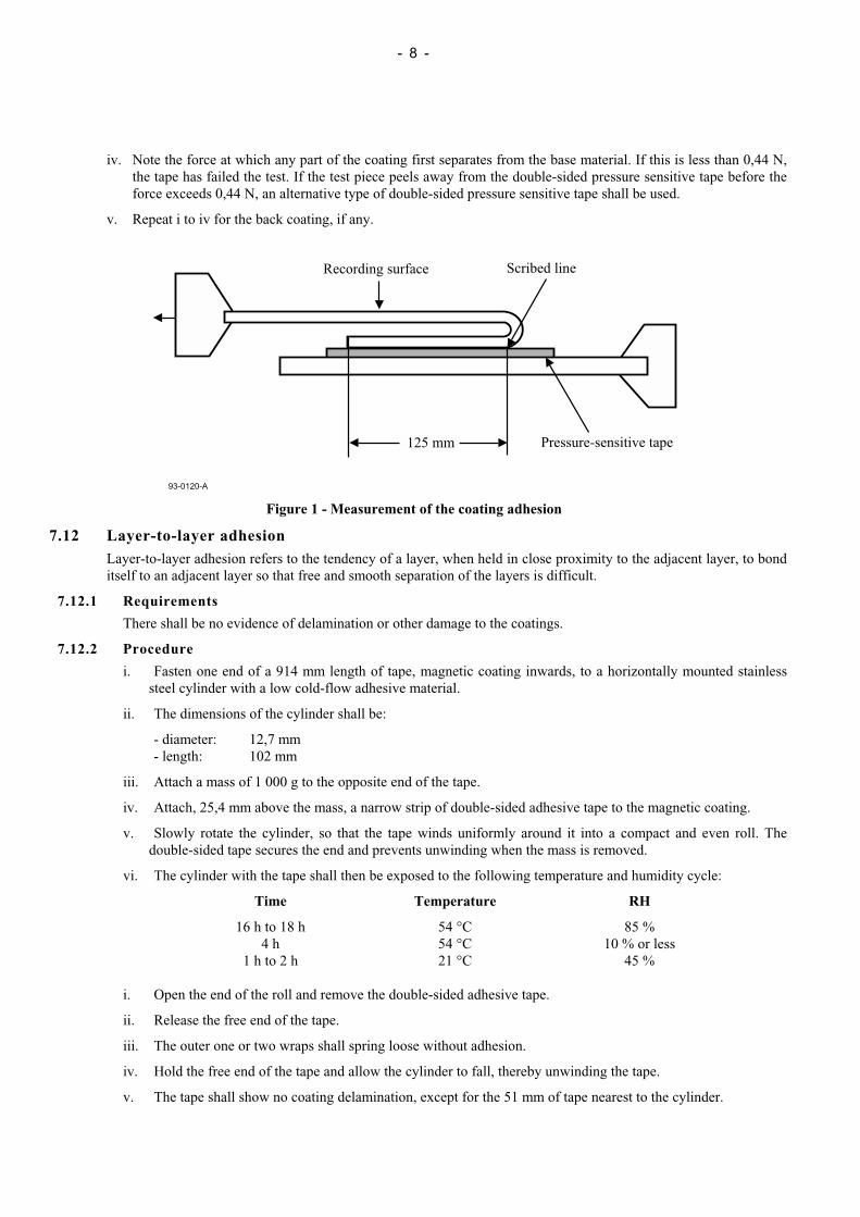
i. Take a test piece of the tape approximately 380 mm long and scribe a line through the recording coating acrossthe width of the tape 125 mm from one end.
ii. Using a double-sided pressure sensitive tape, attach the full width of the test piece to a smooth metal plate, withthe magnetic coating (recording surface) facing the plate, as shown in figure 1.
iii. Fold the test piece over 180 °, adjacent to, and parallel with, the scribed line. Attach the metal plate and the freeend of the test piece to the jaws of a universal testing machine and set the speed of the jaw separation to 254 mmper min.
- 8 -
iv. Note the force at which any part of the coating first separates from the base material. If this is less than 0,44 N,the tape has failed the test. If the test piece peels away from the double-sided pressure sensitive tape before theforce exceeds 0,44 N, an alternative type of double-sided pressure sensitive tape shall be used.
v. Repeat i to iv for the back coating, if any.
93-0120-A
Recording surface Scribed line
Pressure-sensitive tape125 mm
Figure 1 - Measurement of the coating adhesion
7.12 Layer-to-layer adhesionLayer-to-layer adhesion refers to the tendency of a layer, when held in close proximity to the adjacent layer, to bonditself to an adjacent layer so that free and smooth separation of the layers is difficult.
7.12.1 Requirements
There shall be no evidence of delamination or other damage to the coatings.
7.12.2 Procedure
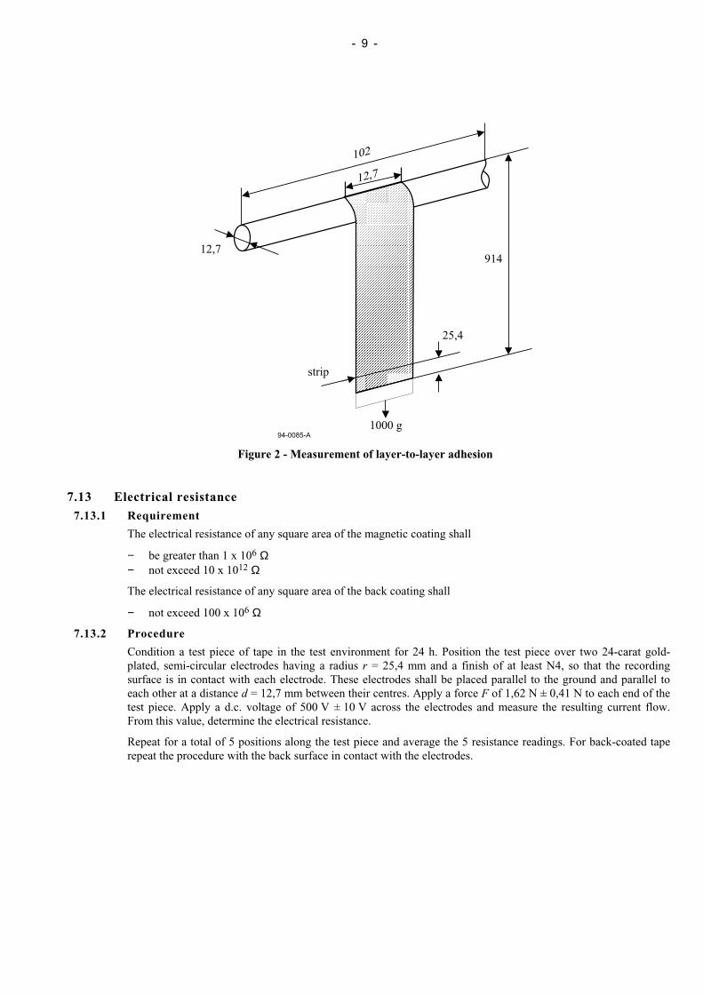
i. Fasten one end of a 914 mm length of tape, magnetic coating inwards, to a horizontally mounted stainlesssteel cylinder with a low cold-flow adhesive material.
ii. The dimensions of the cylinder shall be:
- diameter: 12,7 mm- length: 102 mm
iii. Attach a mass of 1 000 g to the opposite end of the tape.
iv. Attach, 25,4 mm above the mass, a narrow strip of double-sided adhesive tape to the magnetic coating.
v. Slowly rotate the cylinder, so that the tape winds uniformly around it into a compact and even roll. Thedouble-sided tape secures the end and prevents unwinding when the mass is removed.
vi. The cylinder with the tape shall then be exposed to the following temperature and humidity cycle:
Time Temperature RH
16 h to 18 h 54 °C 85 %4 h 54 °C 10 % or less
1 h to 2 h 21 °C 45 %
i. Open the end of the roll and remove the double-sided adhesive tape.
ii. Release the free end of the tape.
iii. The outer one or two wraps shall spring loose without adhesion.
iv. Hold the free end of the tape and allow the cylinder to fall, thereby unwinding the tape.
v. The tape shall show no coating delamination, except for the 51 mm of tape nearest to the cylinder.
- 9 -
94-0085-A
102
12,7
12,7914
25,4
strip
1000 g
Figure 2 - Measurement of layer-to-layer adhesion
7.13 Electrical resistance7.13.1 Requirement
The electrical resistance of any square area of the magnetic coating shall
− be greater than 1 x 10⁶ Ω− not exceed 10 x 1012 Ω
The electrical resistance of any square area of the back coating shall
− not exceed 100 x 106 Ω
7.13.2 Procedure
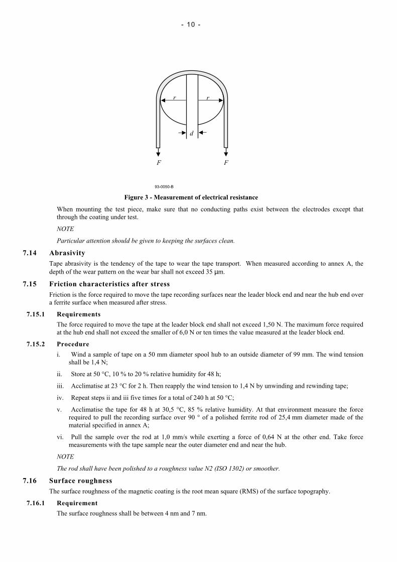
Condition a test piece of tape in the test environment for 24 h. Position the test piece over two 24-carat gold-plated, semi-circular electrodes having a radius r = 25,4 mm and a finish of at least N4, so that the recordingsurface is in contact with each electrode. These electrodes shall be placed parallel to the ground and parallel toeach other at a distance d = 12,7 mm between their centres. Apply a force F of 1,62 N ± 0,41 N to each end of thetest piece. Apply a d.c. voltage of 500 V ± 10 V across the electrodes and measure the resulting current flow.From this value, determine the electrical resistance.
Repeat for a total of 5 positions along the test piece and average the 5 resistance readings. For back-coated taperepeat the procedure with the back surface in contact with the electrodes.
- 10 -
d
rr
F F
93-0050-B
Figure 3 - Measurement of electrical resistance
When mounting the test piece, make sure that no conducting paths exist between the electrodes except thatthrough the coating under test.
NOTE
Particular attention should be given to keeping the surfaces clean.
7.14 AbrasivityTape abrasivity is the tendency of the tape to wear the tape transport. When measured according to annex A, thedepth of the wear pattern on the wear bar shall not exceed 35 µm.
7.15 Friction characteristics after stressFriction is the force required to move the tape recording surfaces near the leader block end and near the hub end overa ferrite surface when measured after stress.
7.15.1 Requirements
The force required to move the tape at the leader block end shall not exceed 1,50 N. The maximum force requiredat the hub end shall not exceed the smaller of 6,0 N or ten times the value measured at the leader block end.
7.15.2 Procedure
i. Wind a sample of tape on a 50 mm diameter spool hub to an outside diameter of 99 mm. The wind tensionshall be 1,4 N;
ii. Store at 50 °C, 10 % to 20 % relative humidity for 48 h;
iii. Acclimatise at 23 °C for 2 h. Then reapply the wind tension to 1,4 N by unwinding and rewinding tape;
iv. Repeat steps ii and iii five times for a total of 240 h at 50 °C;
v. Acclimatise the tape for 48 h at 30,5 °C, 85 % relative humidity. At that environment measure the forcerequired to pull the recording surface over 90 ° of a polished ferrite rod of 25,4 mm diameter made of thematerial specified in annex A;
vi. Pull the sample over the rod at 1,0 mm/s while exerting a force of 0,64 N at the other end. Take forcemeasurements with the tape sample near the outer diameter end and near the hub.
NOTE
The rod shall have been polished to a roughness value N2 (ISO 1302) or smoother.
7.16 Surface roughnessThe surface roughness of the magnetic coating is the root mean square (RMS) of the surface topography.
7.16.1 Requirement
The surface roughness shall be between 4 nm and 7 nm.
- 11 -
7.16.2 Procedure
Use a WYKO 3D Profiler with a 512 by 512 pixel array detector and 20X magnification, or equivalent. Take theaverage of at least three samples.
7.17 Inhibitor tapeThis ECMA Standard does not specify parameters for assessing whether or not a tape is an inhibitor tape. However,annex F gives further information on inhibitor tapes.
8 Magnetic recording characteristicsThe magnetic recording characteristics shall be defined by testing the requirements given below.
When performing the tests, the output or resultant signal shall be measured on the same relative pass for both a tapecalibrated to the Master Standard Reference Tape and the tape under test (read-while-write, or on equipment withoutread-while-write capability, on the first forward-read-pass) on the same equipment.
The following conditions shall apply to the testing of all magnetic recording characteristics, unless otherwise noted.
− Tape condition: anhysteretically erased
− Tape speed: 2,00 m/s ± 0,05 m/s
− Read track: within the written track
− Azimuth alignment: 6 ' max. between the mean write transitions and the read gap
− Write gap length: 0,9 µm ± 0,1 µm
− Write head saturation density: 8 000 G ± 800 G
− Tape tension: 1,4 N ± 0,2 N
− Recording current: Test Recording Current (Im)
− Physical recording densities: 1f = 2 550 ftpmm 4f = 10 200 ftpmm
The method of recording shall be as defined in clause 11.
8.1 Typical FieldThe Typical Field shall be between 90 % and 110 % of the Reference Field.
Traceability to the Reference Field is provided by the calibration factors supplied with each Secondary StandardReference Tape.
8.2 Signal amplitudeThe Average Signal Amplitude at the physical recording density of 2 550 ftpmm shall be between 75 % and 125 %of the SRA.
Traceability to the SRA is provided by the calibration factors supplied with each Secondary Standard ReferenceTape.
8.3 ResolutionThe ratio of the average signal amplitude at the physical recording density of 2 550 ftpmm to that at the physicalrecording density of 4 000 ftpmm shall be between 80 % and 120 % of the same ratio for the Master StandardReference Tape.
Traceability to the resolution of the Master Standard Reference Tape is provided by the calibration factors suppliedwith each Secondary Standard Reference Tape.
8.4 Broad-band signal-to-noise ratio (BBSNR)The BBSNR is the ratio of average signal power to average integrated broad band (floor) noise power.
8.4.1 Requirement
The BBSNR of the tape shall not be lower than that of the Master Standard Reference Tape by more than 2,8 dB.
- 12 -
Traceability to the standard reference BBSNR is provided by the calibration factors supplied with each SecondaryStandard Reference Tape.
The noise level of the measuring system shall be well below the noise level of the tape under test.
8.4.2 Procedure
i. Record a signal on the track at 2 550 ftpmm;
ii. Measure the signal power, averaging a minimum of 100 samples over 50 m of tape;
iii. Measure the noise power of the written signal over a 300 kHz to 1 500 kHz bandwidth;
iv. Calculate the BBSNR as the average signal power divided by the integrated noise power, converted to dBusing the equation BBSNR = 10 × log10 (S/N).
9 Tape qualityThe quality of the tape (including the effects of exposure to storage and shipping environments) shall be defined by thetesting requirements given in the following paragraphs. The following conditions shall apply to all quality testingrequirements:
− Tape condition: pre-record condition
− Tape speed: 2,00 m/s ± 0,05 m/s
− Write-track width: 35 µm min.
− Read-track: 35 µm
− Azimuth alignment: 6 ' max. between the mean write transitions and the read gap
− Write-gap length: 0,9 µm ± 0,1 µm
− Write head saturation density: 8 000 G ± 800 G
− Tape tension: 1,4 N ± 0,2 N
− Recording current: Test Recording Current (Im )
− Recording density: 2 550 ftpmm
9.1 Missing pulseA missing pulse is a loss of read signal amplitude detected after writing at the physical recording density of2 550 ftpmm. A missing pulse shall exist when the base-to-peak read signal amplitude is 25 % or less of half of theaverage signal amplitude (peak-to-peak) for the preceding 25,4 mm of tape.
9.1.1 Requirement
The average missing pulse rate shall be less than one missing pulse for each 5 × 10⁶ flux transitions recorded. Inaddition, no single track shall have a mean missing pulse separation less than 2,5 × 10⁵ flux transitions recorded.
9.1.2 Procedure
i. While reading the signal of single tracks, observe and count all missing pulses. When a missing pulse isdetected, a second missing pulse shall not be counted until 48 consecutive missing pulse-free flux transitionsare read. If a missing pulse persists for a distance of 0,7 mm, another missing pulse shall be counted.
ii. Calculate the missing pulse rate by dividing the number of missing pulses counted by the total number of fluxtransitions recorded on the tape.
iii. Calculate the mean missing pulse separation for each individual track by dividing the number of fluxtransitions recorded on a track by the number of missing pulses on the same track.
iv. The average missing pulse rate shall be the total number of flux transitions recorded on tape divided by thenumber of missing pulses counted.

- 13 -
9.2 Coincident missing pulseA coincident missing pulse is a simultaneous missing pulse condition on five or more tracks of a sixteen-track group.A coincident missing pulse shall be counted as a single event regardless of length. There are eight sixteen-trackgroups in the format, as shown in table 2. (See 13.5.)
9.2.1 Requirement
No cartridge shall have more than 10 coincident missing pulses. No coincident missing pulse shall be longer than25 mm.
9.2.2 Procedure
i. While reading the signals of a sixteen-track group, observe and count all coincident missing pulses.
ii. Measure the length of each coincident missing pulse from the start of the earliest event to the completion ofthe last event.
9.3 Missing pulse densityMissing pulse density is the number of tracks within a sixteen-track group that contain missing pulses in a givensection of tape. A section of tape for a 16-track group for this requirement shall be a tape length of 0,7 mm.
9.3.1 Requirement
There shall be no events as defined in the following procedure for a cartridge.
9.3.2 Procedure
i. While reading the signals of a 16-track group, observe for the occurrence of a missing pulse longer than0,16 mm and start counting the tracks of the 16-track group that have missing pulses during the subsequent 8sections;
ii. Count the number of tracks that have missing pulses over the first 2 sections and also over the first 8 sections.An event shall be having 5 or more error tracks in the first 2 sections, or 13 or more error tracks in the 8sections.
9.4 Tape durabilityThis ECMA Standard does not specify parameters for assessing tape durability. However, a recommended procedureis described in annex G.
Section 3 - Mechanical specifications of the tape cartridge
10 GeneralThe tape cartridge shall consist of the following elements
− a case,− a reel for the magnetic tape,− a locking mechanism for the reel,− a magnetic tape wound on the hub of the reel,− a write-inhibit mechanism,− a leader block,− a latching mechanism for the leader block.
Dimensional characteristics are specified for those parameters deemed mandatory for interchange and compatible useof the cartridge. Where there is freedom of design, only the functional characteristics of the elements described areindicated. In the enclosed drawings a typical implementation is represented in third angle projection. Figures 4 to 21show a typical implementation.
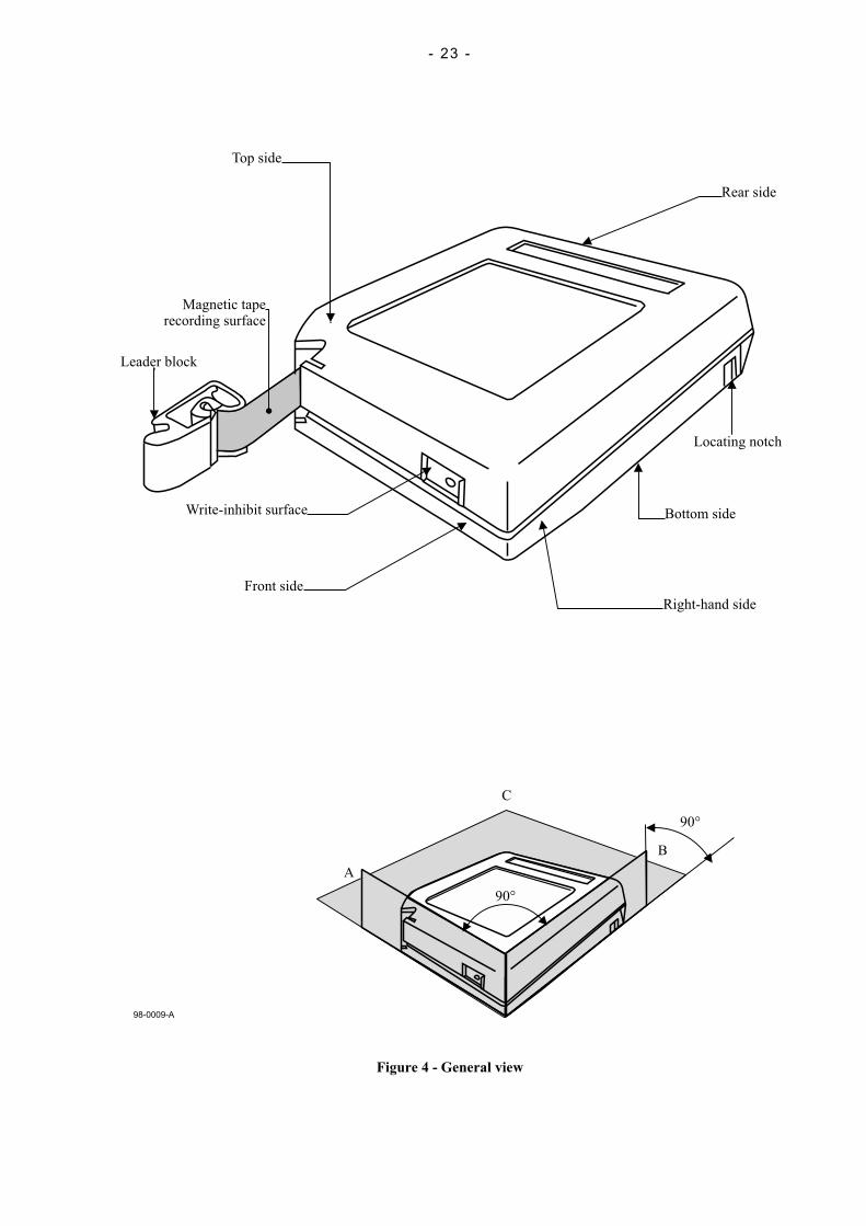
Where they are purely descriptive, the dimensions refer to three reference surfaces; A, B, and C which form ageometrical trihedral (see figure 4). Where the dimensions are related to the position of the cartridge in the drive, theymay be referred to another surface of the cartridge.
Figure 4 shows a general view of the whole cartridge.Figure 5 shows the top side of the case.
- 14 -
Figure 6 shows the front side of the case.Figure 7 shows the rear side of the case.Figure 8 shows the bottom side of the case.Figure 8a shows an enlarged partial view of figure 8.Figure 9 shows the side of the case.Figure 10 shows an enlarged cross-section of leader block opening.Figure 11 shows an enlarged view of a location notch.Figure 12 shows a detail view of the opening in the case.Figure 13 shows an enlarged partial cross-section of the cartridge in the non-operating position.Figure 14 shows an enlarged view of the cartridge button.Figure 15 shows the same cross-section as figure 15 but of a cartridge in the operating position.Figure 16 shows schematically the teeth of the toothed rim.Figure 17 shows two views of the leader block.Figure 18 shows the attachment of the tape to the leader block.Figure 19 shows the leader block inserted into the case.
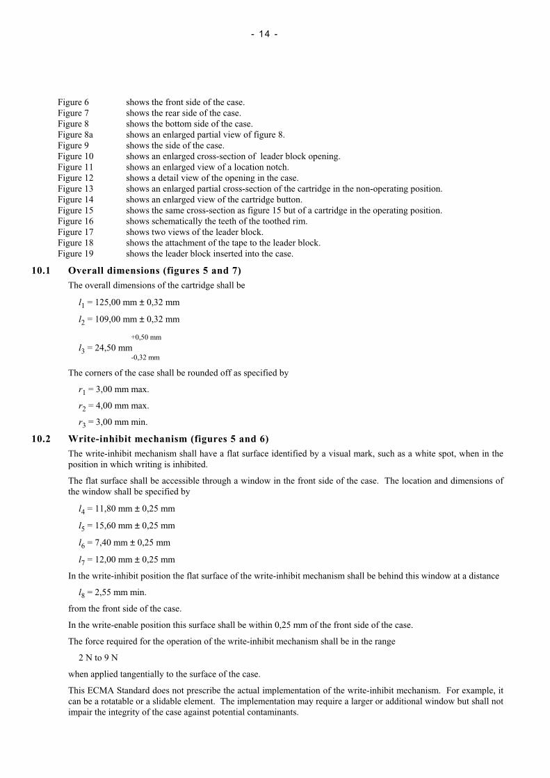
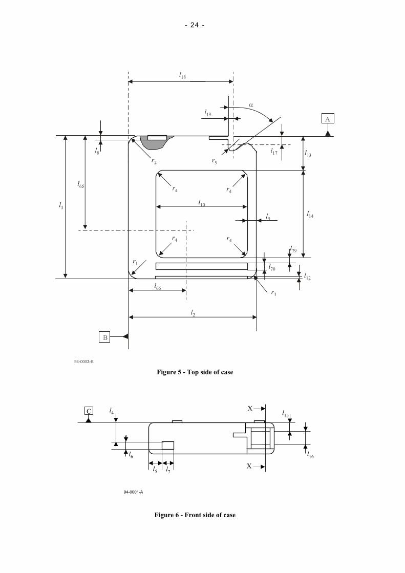
10.1 Overall dimensions (figures 5 and 7)The overall dimensions of the cartridge shall be
l1 = 125,00 mm ± 0,32 mm
l2 = 109,00 mm ± 0,32 mm
+0,50 mm
l3 = 24,50 mm-0,32 mm
The corners of the case shall be rounded off as specified by
r1 = 3,00 mm max.
r2 = 4,00 mm max.
r3 = 3,00 mm min.
10.2 Write-inhibit mechanism (figures 5 and 6)The write-inhibit mechanism shall have a flat surface identified by a visual mark, such as a white spot, when in theposition in which writing is inhibited.
The flat surface shall be accessible through a window in the front side of the case. The location and dimensions ofthe window shall be specified by
l4 = 11,80 mm ± 0,25 mm
l5 = 15,60 mm ± 0,25 mm
l6 = 7,40 mm ± 0,25 mm
l7 = 12,00 mm ± 0,25 mm
In the write-inhibit position the flat surface of the write-inhibit mechanism shall be behind this window at a distance
l8 = 2,55 mm min.
from the front side of the case.
In the write-enable position this surface shall be within 0,25 mm of the front side of the case.
The force required for the operation of the write-inhibit mechanism shall be in the range
2 N to 9 N
when applied tangentially to the surface of the case.
This ECMA Standard does not prescribe the actual implementation of the write-inhibit mechanism. For example, itcan be a rotatable or a slidable element. The implementation may require a larger or additional window but shall notimpair the integrity of the case against potential contaminants.

- 15 -
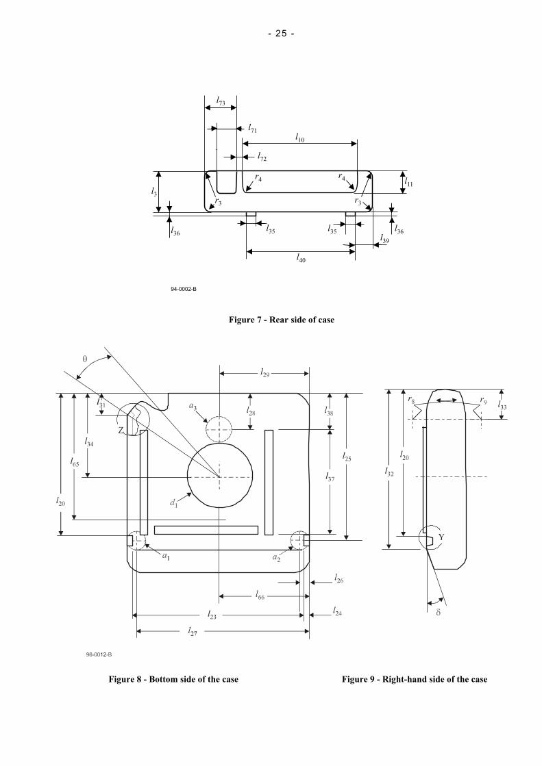
10.3 Label areas of the rear side (figures 5 and 7)On the rear side of the case there shall be two label areas, provided to hold labels
The label area shall be specified by
l9 = 7,00 mm ± 0,25 mm
+0,30 mm
l10 = 80,00 mm-0,16 mm
l11 = 12,30 mm ± 0,25 mm
l12 = 0,50 mm ± 0,25 mm
l71 = 17,55 mm ± 0,13 mm
l72 = 2,41 mm ± 0,13 mm
l73 = 21,97 mm ± 0,25 mm
r4 = 1,00 mm max.
A label bearing a letter J and its associated bar code, and complying with the requirements of annex B, shall beaffixed in the area having dimension l71 and l11.
10.4 Label area on the top side (figure 5)
On the top side of the case there shall have two label areas, recessed by 0,50 mm ± 0,25 mm.
The first label area shall be specified by l9, l10 and in addition by
l13 = 31,00 mm ± 0,25 mm
+0,30 mm
l14 = 75,00 mm-0,16 mm
The second label area shall be specified by l9, l10 and in addition by
l70 = 11,43 mm ± 0,13 mm
l79 = 2,50 mm ± 0,25 mm
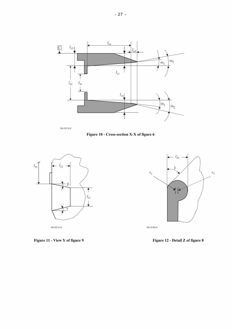
10.5 Case opening (figures 5, 6 and 10)The case shall have an opening for the tape into which the leader block can be inserted (see also figure 19). Thisopening shall be specified by
l15 = 4,70 mm ± 0,25 mm
l16 = 14,90 mm ± 0,32 mm
l17 = 7,50 mm ± 0,25 mm
l18 = 87,10 mm ± 0,25 mm
l19 = 4,00 mm ± 0,25 mm
r5 = 4,00 mm ± 0,25 mm
α = 50 ° ± 1 °
Moreover, figure 10 shows at a larger scale the details of the configuration of the case opening as seen at the right-hand side of figure 5.
l61 = 3,9 mm ± 0,5 mm
+0,5 mm
l62= 16,9 mm-0,4 mm

- 16 -
l63 = 3,0 mm ± 0,5 mm
l64 = 11,6 mm ± 0,5 mm
ω1 = 1 ° 0 ' ± 30 '
ω2 = 20 ° ± 2 °
10.6 Locating notches (figures 8, 9 and 11)There shall be two locating notches open towards the bottom side. These location notches shall be specified by
l20 = 106,00 mm ± 0,25 mm
l21= 5,00 mm ± 0,25 mm
l22 = 7,00 mm ± 0,25 mm
l23 = 104,00 mm ± 0,25 mm
l24 = 2,50 mm ± 0,25 mm
β = 1 ° 30 ' ± 30 '
γ = 2 ° 0 ' ± 30 '
10.7 Locating areas (figure 8)The bottom side of the case shall have three circular locating areas a1, a2, and a3 which shall lie in the samehorizontal plane within 0,25 mm.
Areas a1 and a2 shall have a diameter of 10,00 mm ± 0,25 mm. The position of their centre shall be specified by
l25 = 108,50 mm ± 0,25 mm
l26 = 3,50 mm ± 0,25 mm
l27 = 105,50 mm ± 0,25 mm
Area a3 shall have a diameter of 14,00 mm ± 0,25 mm. The position of its centre shall be specified by
l28 = 31,25 mm ± 0,25 mm
l29 = 54,50 mm ± 0,25 mm
10.8 Inside configuration of the case around the case opening (figures 8 and 12)Figures 8 and 12 show the inside configuration of the case around the opening of the case. This configuration shallbe defined as follows (see also 10.10)
l30 = 3,30 mm ± 0,25 mm
l31 = 18,40 mm ± 0,25 mm
r6 = 1,50 mm ± 0,25 mm
r7 = 1,50 mm ± 0,25 mm
The oblique edge of the case shall be tangential to the arc of a circle defined by r6 at an angle
λ = 40 ° 0 ' ± 30 '
10.9 Other external dimensions of the case (figure 9)The external form of the case shall be further specified by
l32 = 113,2 mm ± 0,3 mm
l33 = 26,00 mm ± 0,25 mm
r8 = 145,50 mm ± 0,25 mm
r9 = 145,50 mm ± 0,25 mm

- 17 -
δ = 30 ° 0 ' ± 30 '
10.10 Central window (figure 8)The bottom side of the case shall have a central window. The location of its centre shall be specified by l29 and
l34 = 61,00 mm ± 0,25 mm
Its diameter shall be
+2,00 mm
d1 = 43,50 mm-0,25 mm
The angle with its apex at the centre of this window and formed by the two lines tangential to the parts shown infigure 8 in cross-section shall be
θ = 16 ° 0 ' ± 30 '
10.11 Stacking ribs (figures 7 and 8)The bottom side of the case shall have two parallel stacking ribs. Their dimensions shall be
l35 = 5,00 mm ± 0,25 mm
l36 = 1,00 mm ± 0,16 mm
l37 = 74,50 mm ± 0,25 mm
Their location shall be
l38 = 31,00 mm ± 0,25 mm
l39 = 7,50 mm ± 0,32 mm
l40 = 79,50 mm ± 0,25 mm
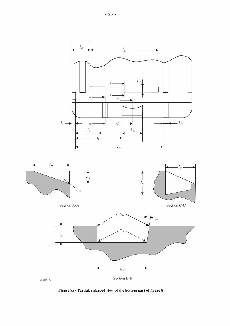
10.12 Recessed area (figure 8a)The bottom of the case shall have a recessed area whose dimensions shall be
+ 0,10 mm
l55 = 0,45 mm- 0,05 mm
l67 = 5,00 mm ± 0,13 mm
l68 = 16,50 mm ± 0,25 mm
l69 = 61,55 mm ± 0,20 mm
µ5 = 2,0 ° max.
r16 = 0,25 mm max.
r17 = 0,10 mm max.
Its location shall be defined by l20.
10.13 Flexibility of the caseThe flexibility of the top and bottom sides of the case (see figure 4) is the amount of deflection observed when theyare submitted to a perpendicular force F.
10.13.1 Requirements
The amount of deflection d shall meet the following requirements
Deflection of the top side
d ≤ 0,38 + 0,054 F
Deflection of the bottom side
- 18 -
d ≤ 0,38 + 0,040 F
where
d is the measured deflection in millimetres, and
4,5 N ≤ F ≤ 54,0 N
10.13.2 Procedure
The flexibility of the case shall be measured in a universal testing machine operating in the compression mode. Asuitable load cell shall be used for the test. Apply a single point load with a radius of 10 mm ± 1 mm on thebottom and subsequently on the top of the cartridge at the points shown in figure 6 and figure 8, and specified by
l65 = 86,9 mm nominal
l66 = 54,5 mm nominal
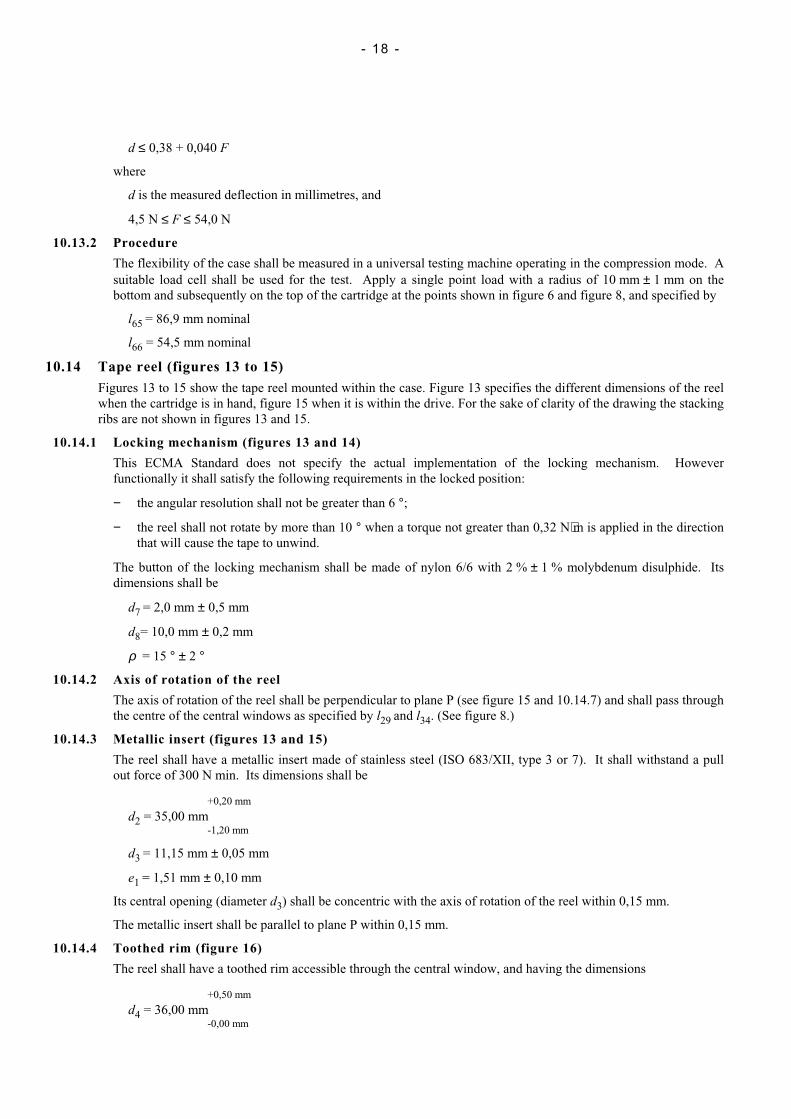
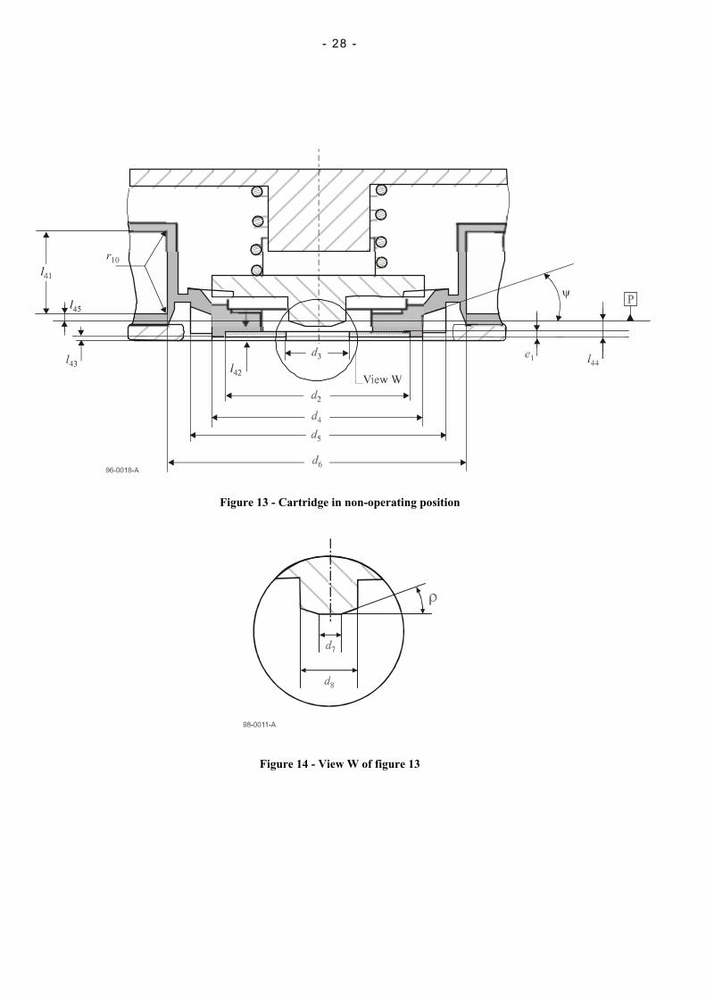
10.14 Tape reel (figures 13 to 15)Figures 13 to 15 show the tape reel mounted within the case. Figure 13 specifies the different dimensions of the reelwhen the cartridge is in hand, figure 15 when it is within the drive. For the sake of clarity of the drawing the stackingribs are not shown in figures 13 and 15.
10.14.1 Locking mechanism (figures 13 and 14)
This ECMA Standard does not specify the actual implementation of the locking mechanism. Howeverfunctionally it shall satisfy the following requirements in the locked position:
− the angular resolution shall not be greater than 6 °;
− the reel shall not rotate by more than 10 ° when a torque not greater than 0,32 N⋅m is applied in the directionthat will cause the tape to unwind.
The button of the locking mechanism shall be made of nylon 6/6 with 2 % ± 1 % molybdenum disulphide. Itsdimensions shall be
d7 = 2,0 mm ± 0,5 mm
d8= 10,0 mm ± 0,2 mm
ρ = 15 ° ± 2 °
10.14.2 Axis of rotation of the reel
The axis of rotation of the reel shall be perpendicular to plane P (see figure 15 and 10.14.7) and shall pass throughthe centre of the central windows as specified by l29 and l34. (See figure 8.)
10.14.3 Metallic insert (figures 13 and 15)
The reel shall have a metallic insert made of stainless steel (ISO 683/XII, type 3 or 7). It shall withstand a pullout force of 300 N min. Its dimensions shall be
+0,20 mm
d2 = 35,00 mm-1,20 mm
d3 = 11,15 mm ± 0,05 mm
e1 = 1,51 mm ± 0,10 mm
Its central opening (diameter d3) shall be concentric with the axis of rotation of the reel within 0,15 mm.
The metallic insert shall be parallel to plane P within 0,15 mm.
10.14.4 Toothed rim (figure 16)
The reel shall have a toothed rim accessible through the central window, and having the dimensions
+0,50 mm
d4 = 36,00 mm-0,00 mm

- 19 -
d5 = 41,00 mm ± 0,25 mm
ψ = 11° 3' ± 5'
10.14.5 Hub of the reel (figure 13)
The hub of the reel shall have a diameter
+0,0 mm
d6 = 50,0 mm-0,2 mm
Further dimensions of the hub shall bel41 = 13,05 mm ± 0,20
when measured at the hub surface, and
r10 = 0,08 mm max.
The hub shall meet the following requirements
− the straightness of the hub surface shall be within 0,04 mm,
− the perpendicularity to the plane P through the pitch line of the teeth of the rim (see 10.14.7) shall be within0,07 mm,
− the ratio of the difference in the diameters d6 of any two sections (perpendicular to the axis) to the distancebetween these sections shall not exceed 0,003 8,
− the rate of change across the width of the hub surface shall not exceed 0,025 mm per mm,
− the total runout of the hub related to the cylinder perpendicular to the circular pitch line (see 10.14.7) of theteeth of the toothed rim shall not exceed 0,2 mm total indicator reading.
10.14.6 Relative positions
10.14.6.1 With the cartridge held in the hand (figure 13)
− the distance of the tip of the button of the locking mechanism to Reference Surface C shall be
+1,40 mm
l42 = 1,90 mm-0,90 mm
− the distance from the bottom surface of the metallic insert to Reference Surface C shall be
+1,0 mm
l43 = 0,4 mm-0,5 mm
10.14.6.2 Whether the cartridge is in the hand or in the drive (figures 13 and 15)
− the distance from the bottom surface of the metallic insert to plane P shall be
l44 = 2,27 mm ± 0,12 mm
− the distance of the inside of the lower flange of the reel to plane P shall be
+0,127 mm
l45 = 0,650 mm-0,090 mm
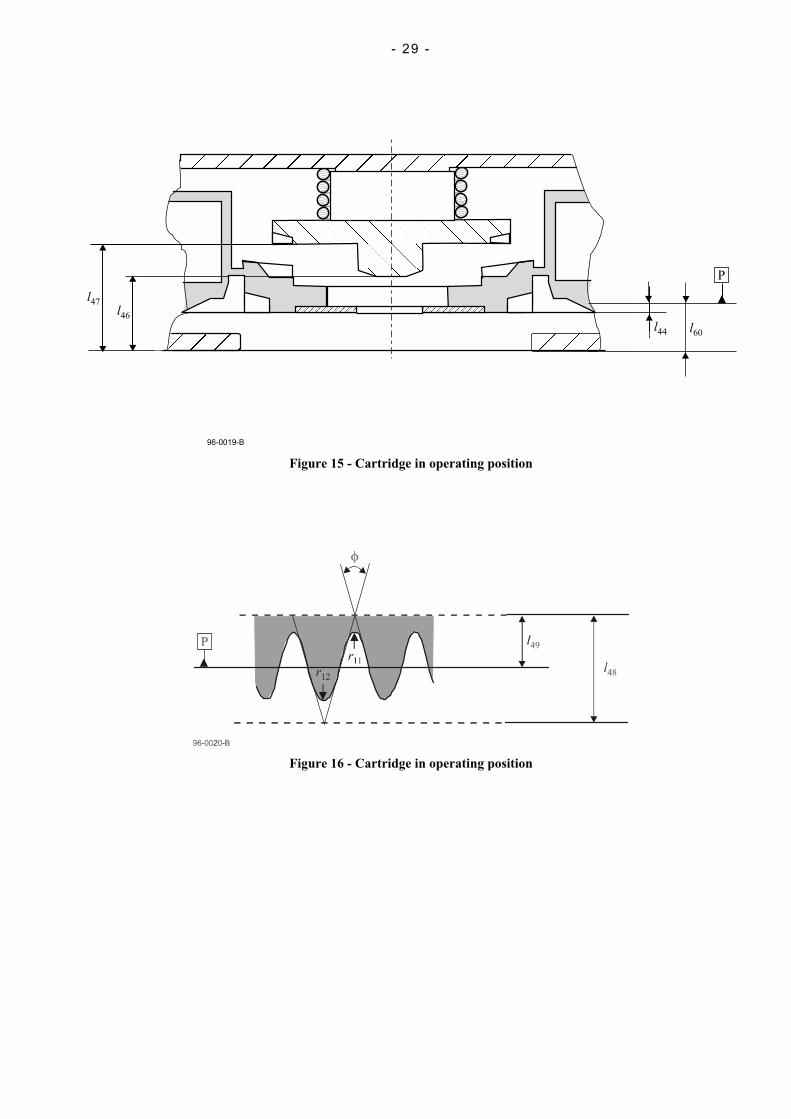
10.14.6.3 With the cartridge in the drive (figure 15)
− the distance from the tip of the button of the locking mechanism to Reference Surface C shall be
l46 = 8,1 mm ± 0,2 mm
− the force required to move the button into this position shall not exceed 12,25 N,
− the distance from the centreline of the tape to Reference Surface C shall be
l47 = 12,25 mm nominal

- 20 -
− the distance from the Reference Surface C to plane P (see 10.14.7) shall be
l60 = 5,04 mm ± 0,20 mm
10.14.7 Characteristics of the toothed rim (figure 16)
The toothed rim shall comprise 60 teeth spaced at an angle of
6 ° 0 ' ± 5 ' non-cumulative
The teeth are specified at the pitch diameter d5 by
l48 = 4 mm nominal
l49 = 2 mm nominal
φ = 30 ° nominal
The pitch line is the circumference of the teeth taken at the distance l49. The plane in which it lies is the plane Pmentioned above.
The blend radius at the bottom of the teeth shall be
r11 = 0,25 mm max.
The blend radius at the tip of the teeth shall be
r12 = 0,2 mm ± 0,1 mm
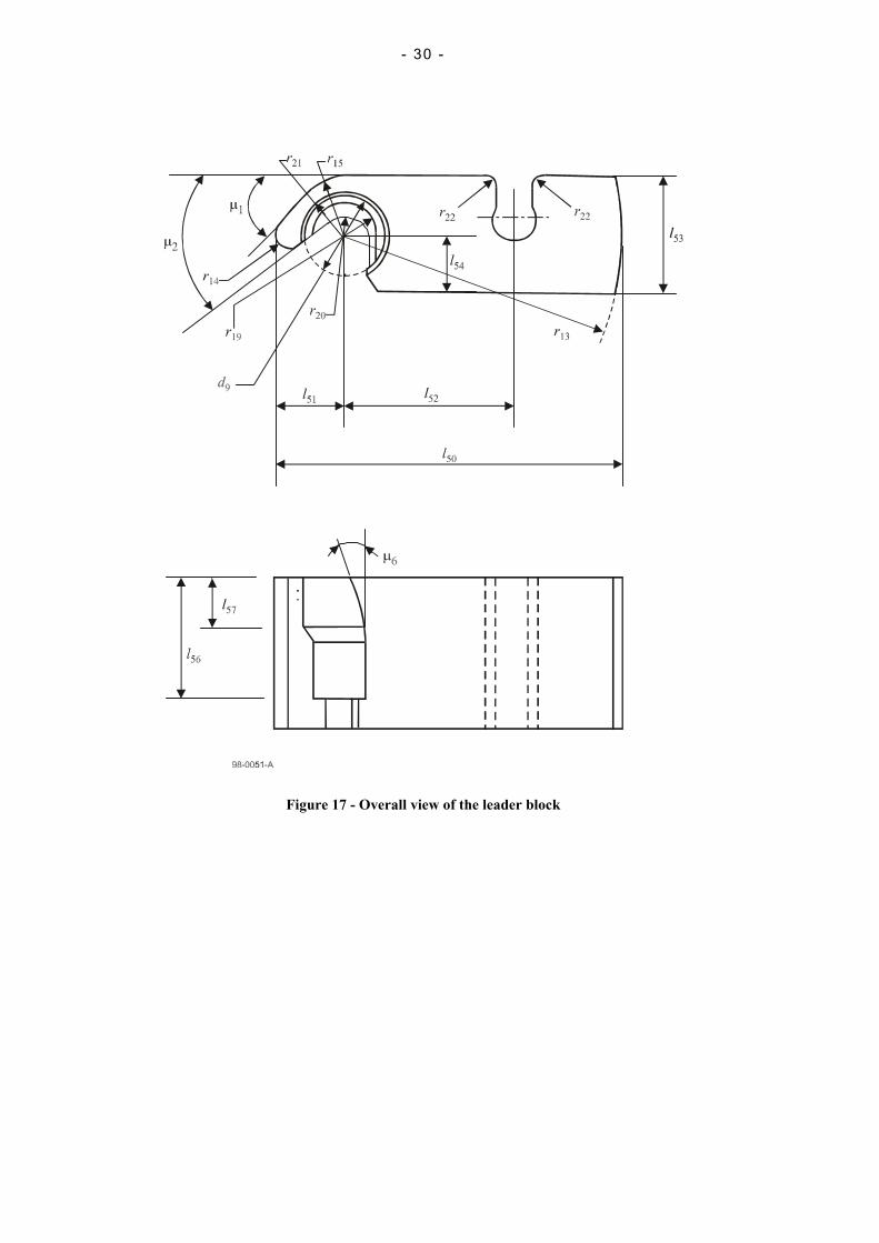
10.15 Leader block (figure 17)The leader block shall have the following dimensions.
l50 = 31,80 mm ± 0,04 mm
l51 = 6,8 mm ± 0,1 mm
l52 = 15,0 mm ± 0,2 mm
+0,06 mm
l53 = 10,93 mm-0,08 mm
l54 = 5,46 mm ± 0,10 mm
+0,0 mm
l56 = 16,5 mm-0,2 mm
l57 = 5,2 mm ± 0,2 mm
+0,20 mmr19 = 3,05 mm
-0,00 mm
r13 = 25,00 mm ± 0,25 mm
r14 = 1,4 mm ± 0,2 mm
r15 = 5,50 mm nominal
r20 = 2,01 mm ± 0,13 mm
r21 = 4,19 mm ± 0,13 mm
r22 = 1,00 mm ± 0,13 mm
d9 = 7,9 mm ± 0,1 mm
µ1 = 48 ° 45’ nominal
µ2 = 36 ° nominal
µ6 = 15 ° 0’ nominal
- 21 -
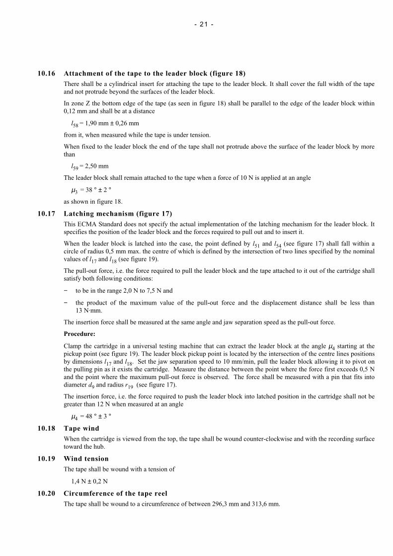
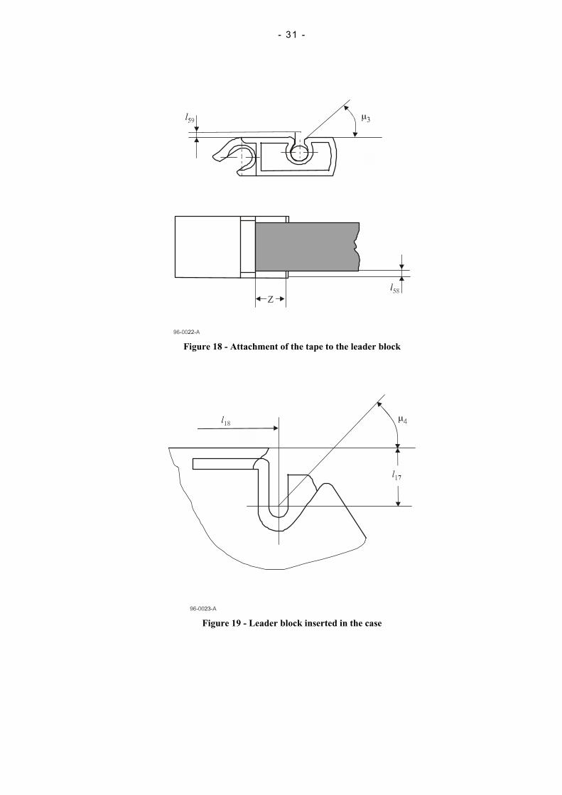
10.16 Attachment of the tape to the leader block (figure 18)There shall be a cylindrical insert for attaching the tape to the leader block. It shall cover the full width of the tapeand not protrude beyond the surfaces of the leader block.
In zone Z the bottom edge of the tape (as seen in figure 18) shall be parallel to the edge of the leader block within0,12 mm and shall be at a distance
l58 = 1,90 mm ± 0,26 mm
from it, when measured while the tape is under tension.
When fixed to the leader block the end of the tape shall not protrude above the surface of the leader block by morethan
l59 = 2,50 mm
The leader block shall remain attached to the tape when a force of 10 N is applied at an angle
µ3 = 38 ° ± 2 °
as shown in figure 18.
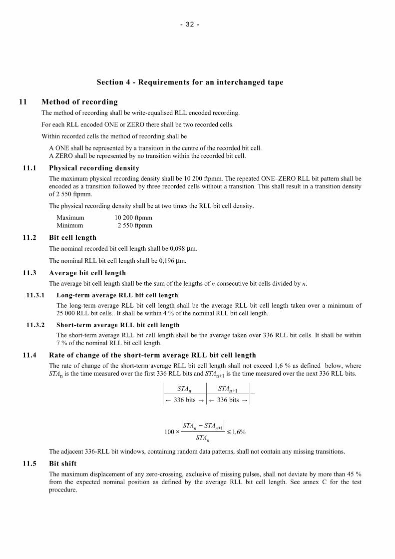
10.17 Latching mechanism (figure 17)This ECMA Standard does not specify the actual implementation of the latching mechanism for the leader block. Itspecifies the position of the leader block and the forces required to pull out and to insert it.
When the leader block is latched into the case, the point defined by l51 and l54 (see figure 17) shall fall within acircle of radius 0,5 mm max. the centre of which is defined by the intersection of two lines specified by the nominalvalues of l17 and l18 (see figure 19).
The pull-out force, i.e. the force required to pull the leader block and the tape attached to it out of the cartridge shallsatisfy both following conditions:
− to be in the range 2,0 N to 7,5 N and
− the product of the maximum value of the pull-out force and the displacement distance shall be less than13 N.mm.
The insertion force shall be measured at the same angle and jaw separation speed as the pull-out force.
Procedure:
Clamp the cartridge in a universal testing machine that can extract the leader block at the angle µ4 starting at thepickup point (see figure 19). The leader block pickup point is located by the intersection of the centre lines positionsby dimensions l17 and l18. Set the jaw separation speed to 10 mm/min, pull the leader block allowing it to pivot onthe pulling pin as it exists the cartridge. Measure the distance between the point where the force first exceeds 0,5 Nand the point where the maximum pull-out force is observed. The force shall be measured with a pin that fits intodiameter d9 and radius r19 (see figure 17).
The insertion force, i.e. the force required to push the leader block into latched position in the cartridge shall not begreater than 12 N when measured at an angle
µ4 = 48 ° ± 3 °
10.18 Tape windWhen the cartridge is viewed from the top, the tape shall be wound counter-clockwise and with the recording surfacetoward the hub.
10.19 Wind tensionThe tape shall be wound with a tension of
1,4 N ± 0,2 N
10.20 Circumference of the tape reelThe tape shall be wound to a circumference of between 296,3 mm and 313,6 mm.
- 22 -
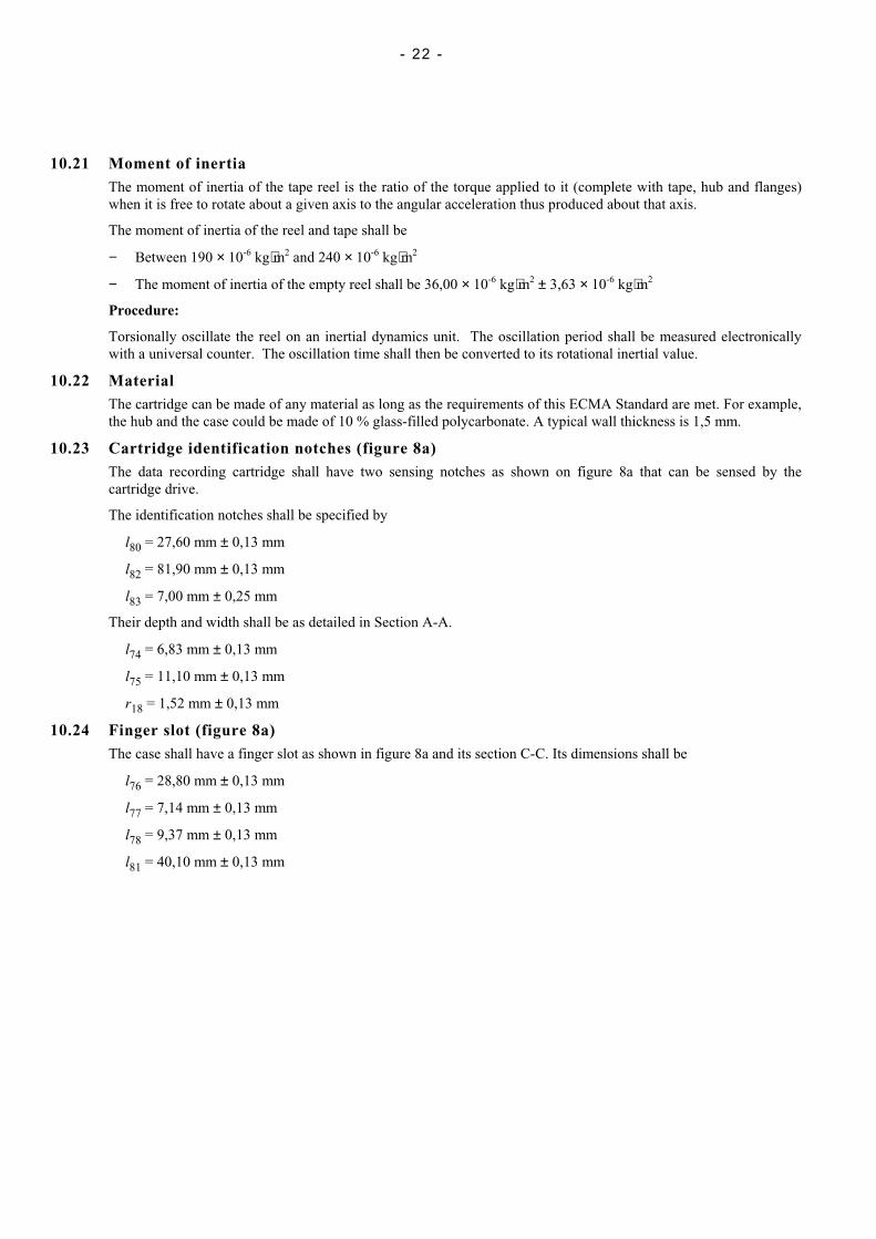
10.21 Moment of inertiaThe moment of inertia of the tape reel is the ratio of the torque applied to it (complete with tape, hub and flanges)when it is free to rotate about a given axis to the angular acceleration thus produced about that axis.
The moment of inertia of the reel and tape shall be
− Between 190 × 10-6 kg⋅m2 and 240 × 10-6 kg⋅m2
− The moment of inertia of the empty reel shall be 36,00 × 10⁻⁶ kg⋅m2 ± 3,63 × 10⁻⁶ kg⋅m2
Procedure:
Torsionally oscillate the reel on an inertial dynamics unit. The oscillation period shall be measured electronicallywith a universal counter. The oscillation time shall then be converted to its rotational inertial value.
10.22 MaterialThe cartridge can be made of any material as long as the requirements of this ECMA Standard are met. For example,the hub and the case could be made of 10 % glass-filled polycarbonate. A typical wall thickness is 1,5 mm.
10.23 Cartridge identification notches (figure 8a)The data recording cartridge shall have two sensing notches as shown on figure 8a that can be sensed by thecartridge drive.
The identification notches shall be specified by
l80 = 27,60 mm ± 0,13 mm
l82 = 81,90 mm ± 0,13 mm
l83 = 7,00 mm ± 0,25 mm
Their depth and width shall be as detailed in Section A-A.
l74 = 6,83 mm ± 0,13 mm
l75 = 11,10 mm ± 0,13 mm
r18 = 1,52 mm ± 0,13 mm
10.24 Finger slot (figure 8a)The case shall have a finger slot as shown in figure 8a and its section C-C. Its dimensions shall be
l76 = 28,80 mm ± 0,13 mm
l77 = 7,14 mm ± 0,13 mm
l78 = 9,37 mm ± 0,13 mm
l81 = 40,10 mm ± 0,13 mm
- 23 -
98-0009-A
Magnetic taperecording surface
Leader block
Front side
Rear side
Top side
Locating notch
Bottom side
Right-hand side
90°
B
A
90°
C
Write-inhibit surface
Figure 4 - General view
- 24 -
Figure 5 - Top side of case
C l4
l5 l7
X
X
l16l6
l15
94-0001-A
Figure 6 - Front side of case
- 25 -
l36l36
l3r3 r3
r4r4
l40
l35 l35
l10
l11
l39
94-0002-B
l72
l71
l73
Figure 7 - Rear side of case
Figure 8 - Bottom side of the case Figure 9 - Right-hand side of the case
- 26 -
Figure 8a - Partial, enlarged view of the bottom part of figure 8
- 27 -
Figure 10 - Cross-section X-X of figure 6
Figure 11 - View Y of figure 9 Figure 12 - Detail Z of figure 8
- 28 -
Figure 13 - Cartridge in non-operating position
Figure 14 - View W of figure 13
- 29 -
96-0019-B
l44
l46
l47
l60
P
Figure 15 - Cartridge in operating position
Figure 16 - Cartridge in operating position
- 30 -
Figure 17 - Overall view of the leader block
- 31 -
Figure 18 - Attachment of the tape to the leader block
Figure 19 - Leader block inserted in the case
- 32 -
Section 4 - Requirements for an interchanged tape
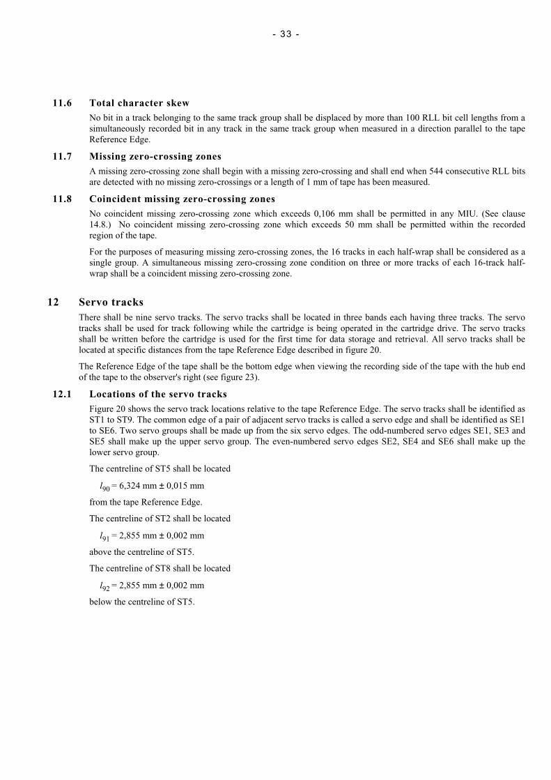
11 Method of recordingThe method of recording shall be write-equalised RLL encoded recording.
For each RLL encoded ONE or ZERO there shall be two recorded cells.
Within recorded cells the method of recording shall be
A ONE shall be represented by a transition in the centre of the recorded bit cell.A ZERO shall be represented by no transition within the recorded bit cell.
11.1 Physical recording densityThe maximum physical recording density shall be 10 200 ftpmm. The repeated ONE–ZERO RLL bit pattern shall beencoded as a transition followed by three recorded cells without a transition. This shall result in a transition densityof 2 550 ftpmm.
The physical recording density shall be at two times the RLL bit cell density.
Maximum 10 200 ftpmmMinimum 2 550 ftpmm
11.2 Bit cell length
The nominal recorded bit cell length shall be 0,098 µm.
The nominal RLL bit cell length shall be 0,196 µm.
11.3 Average bit cell lengthThe average bit cell length shall be the sum of the lengths of n consecutive bit cells divided by n.
11.3.1 Long-term average RLL bit cell length
The long-term average RLL bit cell length shall be the average RLL bit cell length taken over a minimum of25 000 RLL bit cells. It shall be within 4 % of the nominal RLL bit cell length.
11.3.2 Short-term average RLL bit cell length
The short-term average RLL bit cell length shall be the average taken over 336 RLL bit cells. It shall be within7 % of the nominal RLL bit cell length.
11.4 Rate of change of the short-term average RLL bit cell lengthThe rate of change of the short-term average RLL bit cell length shall not exceed 1,6 % as defined below, whereSTAn is the time measured over the first 336 RLL bits and STAn+1 is the time measured over the next 336 RLL bits.
STA STAn n
← → ← →+
336 3361
bits bits
100 1 6%1
×−
≤+STA STA
STA
n n
n
,
The adjacent 336-RLL bit windows, containing random data patterns, shall not contain any missing transitions.
11.5 Bit shiftThe maximum displacement of any zero-crossing, exclusive of missing pulses, shall not deviate by more than 45 %from the expected nominal position as defined by the average RLL bit cell length. See annex C for the testprocedure.
- 33 -
11.6 Total character skewNo bit in a track belonging to the same track group shall be displaced by more than 100 RLL bit cell lengths from asimultaneously recorded bit in any track in the same track group when measured in a direction parallel to the tapeReference Edge.
11.7 Missing zero-crossing zonesA missing zero-crossing zone shall begin with a missing zero-crossing and shall end when 544 consecutive RLL bitsare detected with no missing zero-crossings or a length of 1 mm of tape has been measured.
11.8 Coincident missing zero-crossing zonesNo coincident missing zero-crossing zone which exceeds 0,106 mm shall be permitted in any MIU. (See clause14.8.) No coincident missing zero-crossing zone which exceeds 50 mm shall be permitted within the recordedregion of the tape.
For the purposes of measuring missing zero-crossing zones, the 16 tracks in each half-wrap shall be considered as asingle group. A simultaneous missing zero-crossing zone condition on three or more tracks of each 16-track half-wrap shall be a coincident missing zero-crossing zone.
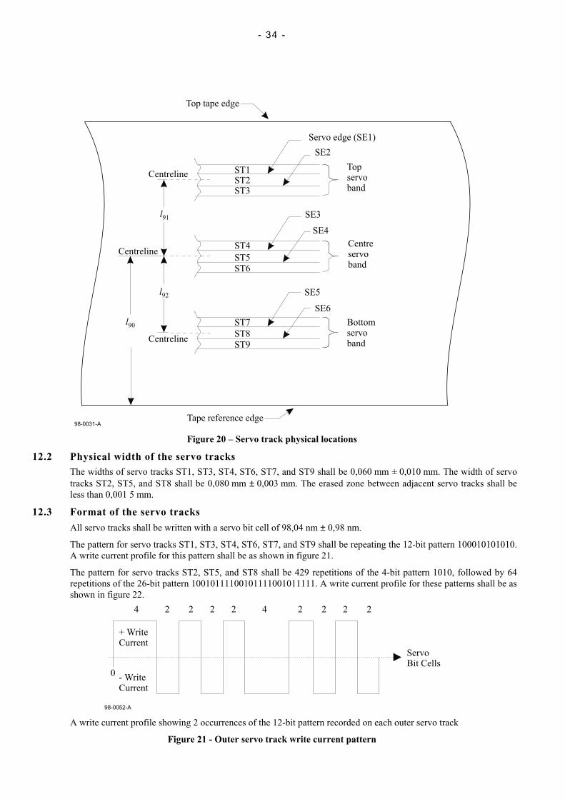
12 Servo tracksThere shall be nine servo tracks. The servo tracks shall be located in three bands each having three tracks. The servotracks shall be used for track following while the cartridge is being operated in the cartridge drive. The servo tracksshall be written before the cartridge is used for the first time for data storage and retrieval. All servo tracks shall belocated at specific distances from the tape Reference Edge described in figure 20.
The Reference Edge of the tape shall be the bottom edge when viewing the recording side of the tape with the hub endof the tape to the observer's right (see figure 23).
12.1 Locations of the servo tracksFigure 20 shows the servo track locations relative to the tape Reference Edge. The servo tracks shall be identified asST1 to ST9. The common edge of a pair of adjacent servo tracks is called a servo edge and shall be identified as SE1to SE6. Two servo groups shall be made up from the six servo edges. The odd-numbered servo edges SE1, SE3 andSE5 shall make up the upper servo group. The even-numbered servo edges SE2, SE4 and SE6 shall make up thelower servo group.
The centreline of ST5 shall be located
l90 = 6,324 mm ± 0,015 mm
from the tape Reference Edge.
The centreline of ST2 shall be located
l91 = 2,855 mm ± 0,002 mm
above the centreline of ST5.
The centreline of ST8 shall be located
l92 = 2,855 mm ± 0,002 mm
below the centreline of ST5.
- 34 -
Servo edge (SE1)
SE2
Topservoband
Centreservoband
Bottomservoband
SE3
SE4
SE5
SE6
ST1ST2ST3
ST4
ST5
ST6
ST7
ST8
ST9Centreline
Centreline
Centreline
Tape reference edge
l90
l91
l92
98-0031-A
Top tape edge
Figure 20 – Servo track physical locations
12.2 Physical width of the servo tracksThe widths of servo tracks ST1, ST3, ST4, ST6, ST7, and ST9 shall be 0,060 mm ± 0,010 mm. The width of servotracks ST2, ST5, and ST8 shall be 0,080 mm ± 0,003 mm. The erased zone between adjacent servo tracks shall beless than 0,001 5 mm.
12.3 Format of the servo tracks
All servo tracks shall be written with a servo bit cell of 98,04 nm ± 0,98 nm.
The pattern for servo tracks ST1, ST3, ST4, ST6, ST7, and ST9 shall be repeating the 12-bit pattern 100010101010.A write current profile for this pattern shall be as shown in figure 21.
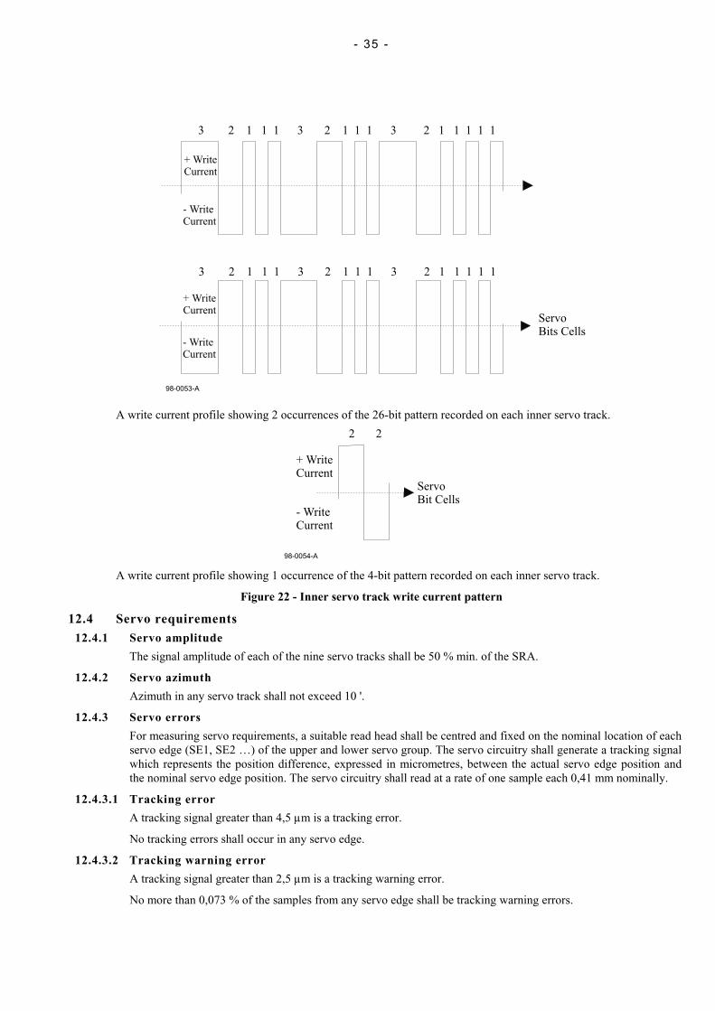
The pattern for servo tracks ST2, ST5, and ST8 shall be 429 repetitions of the 4-bit pattern 1010, followed by 64repetitions of the 26-bit pattern 10010111100101111001011111. A write current profile for these patterns shall be asshown in figure 22.
98-0052-A
0
+ WriteCurrent
- WriteCurrent
ServoBit Cells
4 2 2 2 2 4 2 2 2 2
A write current profile showing 2 occurrences of the 12-bit pattern recorded on each outer servo track
Figure 21 - Outer servo track write current pattern
- 35 -
98-0053-A
3 2 1 1 1 3 2 1 1 1 3 2 1 1 1 1 1
3 2 1 1 1 3 2 1 1 1 3 2 1 1 1 1 1
+ WriteCurrent
+ WriteCurrent
- WriteCurrent
- WriteCurrent
ServoBits Cells
A write current profile showing 2 occurrences of the 26-bit pattern recorded on each inner servo track.
98-0054-A
+ WriteCurrent
- WriteCurrent
ServoBit Cells
2 2
A write current profile showing 1 occurrence of the 4-bit pattern recorded on each inner servo track.
Figure 22 - Inner servo track write current pattern
12.4 Servo requirements12.4.1 Servo amplitude
The signal amplitude of each of the nine servo tracks shall be 50 % min. of the SRA.
12.4.2 Servo azimuth
Azimuth in any servo track shall not exceed 10 '.
12.4.3 Servo errors
For measuring servo requirements, a suitable read head shall be centred and fixed on the nominal location of eachservo edge (SE1, SE2 …) of the upper and lower servo group. The servo circuitry shall generate a tracking signalwhich represents the position difference, expressed in micrometres, between the actual servo edge position andthe nominal servo edge position. The servo circuitry shall read at a rate of one sample each 0,41 mm nominally.
12.4.3.1 Tracking error
A tracking signal greater than 4,5 µm is a tracking error.
No tracking errors shall occur in any servo edge.
12.4.3.2 Tracking warning error
A tracking signal greater than 2,5 µm is a tracking warning error.
No more than 0,073 % of the samples from any servo edge shall be tracking warning errors.

- 36 -
12.4.3.3 Tracking rate error
The difference between sequential tracking signal samples on a servo edge greater than 8 µm is a tracking rateerror.
No more than 0,055 % of the samples on any servo edge shall be tracking rate errors.
No more than one tracking rate error shall occur within any 5 consecutive samples in a servo group.
12.4.3.4 Fade amplitude error
The nominal servo signal amplitude shall be the average amplitude of the previous 100 samples for that servoedge.
A servo signal amplitude sample less than 75 % of the nominal servo signal amplitude is a fade amplitude error.
No fade amplitude errors shall be allowed.
12.4.4 Servo edge spacing
Using the servo circuitry described in 12.4.3, the servo edge spacing between the two servo groups shall be within± 0,001 mm of the nominal spacing between the two servo groups, when averaged over the length of the tape.
The positions of the six servo edges shall be measured simultaneously by reading each of the six elements whichshall be placed over the nominal location of the servo edges. The elements shall be rigidly attached together andshall be aligned perpendicular to the tape within 3,0 mm.
12.5 ProcedureThe checking operation for servo errors shall be conducted by monitoring recorded servo tracks with a fixed readhead and processing the signals as they are read.
13 Data track format13.1 Number of data tracks
There shall be 128 data tracks numbered consecutively from 1 to 128. Track number 1 shall be the track most distantfrom the Reference Edge.
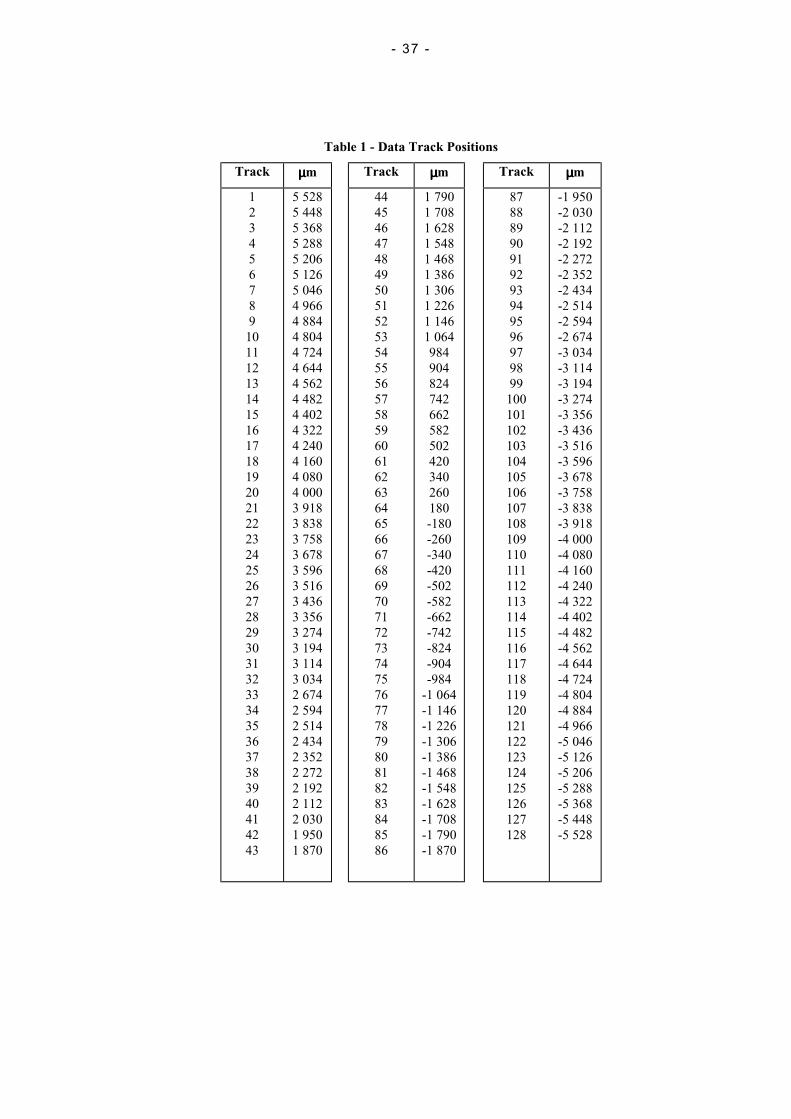
13.2 Track positionsThe position of the data tracks shall be referred to servo track ST5. Table 1 shall indicate the distance of thecentreline of each data track to the centreline of servo track ST5. Data tracks 1 to 64 shall lie above ST5. Data tracks65 to 128 shall lie below servo track ST5. Their positions are shown with a minus sign.
The tolerance shall be 10 µm for all data tracks.
- 37 -
Table 1 - Data Track Positions
Track µµµµm Track µµµµm Track µµµµm
123456789
10111213141516171819202122232425262728293031323334353637383940414243
5 5285 4485 3685 2885 2065 1265 0464 9664 8844 8044 7244 6444 5624 4824 4024 3224 2404 1604 0804 0003 9183 8383 7583 6783 5963 5163 4363 3563 2743 1943 1143 0342 6742 5942 5142 4342 3522 2722 1922 1122 0301 9501 870
44454647484950515253545556575859606162636465666768697071727374757677787980818283848586
1 7901 7081 6281 5481 4681 3861 3061 2261 1461 064984904824742662582502420340260180-180-260-340-420-502-582-662-742-824-904-984
-1 064-1 146-1 226-1 306-1 386-1 468-1 548-1 628-1 708-1 790-1 870
87888990919293949596979899
100101102103104105106107108109110111112113114115116117118119120121122123124125126127128
-1 950-2 030-2 112-2 192-2 272-2 352-2 434-2 514-2 594-2 674-3 034-3 114-3 194-3 274-3 356-3 436-3 516-3 596-3 678-3 758-3 838-3 918-4 000-4 080-4 160-4 240-4 322-4 402-4 482-4 562-4 644-4 724-4 804-4 884-4 966-5 046-5 126-5 206-5 288-5 368-5 448-5 528
- 38 -
13.3 Track width
The width of the written track shall be 80 µm ±3 µm.
13.4 Data azimuthAzimuth in any data track shall not exceed 10 '.
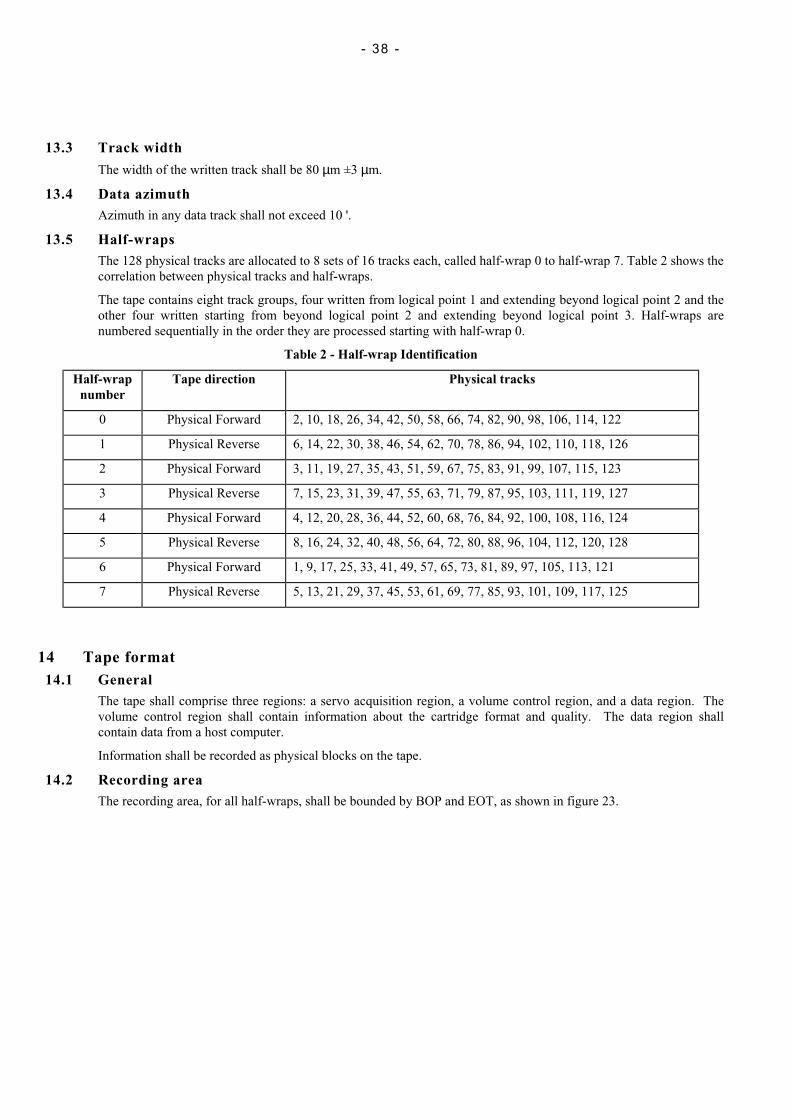
13.5 Half-wrapsThe 128 physical tracks are allocated to 8 sets of 16 tracks each, called half-wrap 0 to half-wrap 7. Table 2 shows thecorrelation between physical tracks and half-wraps.
The tape contains eight track groups, four written from logical point 1 and extending beyond logical point 2 and theother four written starting from beyond logical point 2 and extending beyond logical point 3. Half-wraps arenumbered sequentially in the order they are processed starting with half-wrap 0.
Table 2 - Half-wrap Identification
Half-wrapnumber
Tape direction Physical tracks
0 Physical Forward 2, 10, 18, 26, 34, 42, 50, 58, 66, 74, 82, 90, 98, 106, 114, 122
1 Physical Reverse 6, 14, 22, 30, 38, 46, 54, 62, 70, 78, 86, 94, 102, 110, 118, 126
2 Physical Forward 3, 11, 19, 27, 35, 43, 51, 59, 67, 75, 83, 91, 99, 107, 115, 123
3 Physical Reverse 7, 15, 23, 31, 39, 47, 55, 63, 71, 79, 87, 95, 103, 111, 119, 127
4 Physical Forward 4, 12, 20, 28, 36, 44, 52, 60, 68, 76, 84, 92, 100, 108, 116, 124
5 Physical Reverse 8, 16, 24, 32, 40, 48, 56, 64, 72, 80, 88, 96, 104, 112, 120, 128
6 Physical Forward 1, 9, 17, 25, 33, 41, 49, 57, 65, 73, 81, 89, 97, 105, 113, 121
7 Physical Reverse 5, 13, 21, 29, 37, 45, 53, 61, 69, 77, 85, 93, 101, 109, 117, 125
14 Tape format14.1 General
The tape shall comprise three regions: a servo acquisition region, a volume control region, and a data region. Thevolume control region shall contain information about the cartridge format and quality. The data region shallcontain data from a host computer.
Information shall be recorded as physical blocks on the tape.
14.2 Recording areaThe recording area, for all half-wraps, shall be bounded by BOP and EOT, as shown in figure 23.
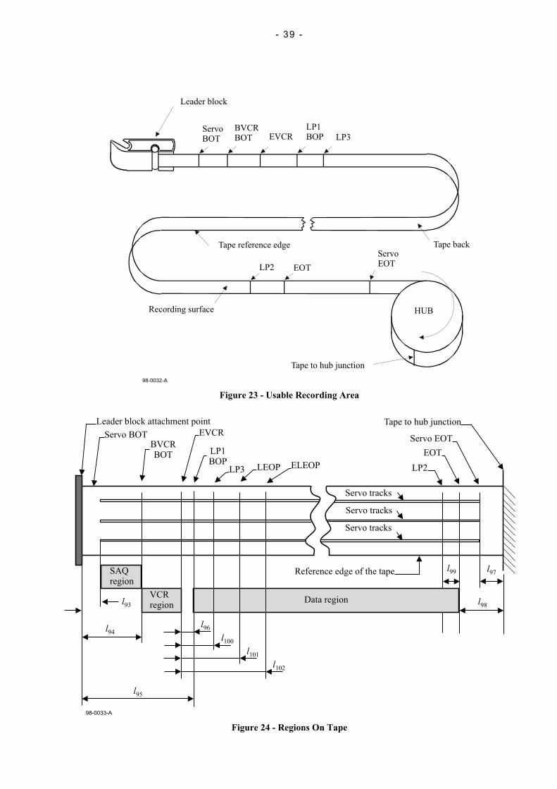
- 39 -
98-0032-A
Leader block
ServoBOT
BVCRBOT EVCR
LP1BOP LP3
Tape reference edge Tape backServoEOT
EOTLP2
HUBRecording surface
Tape to hub junction
Figure 23 - Usable Recording Area
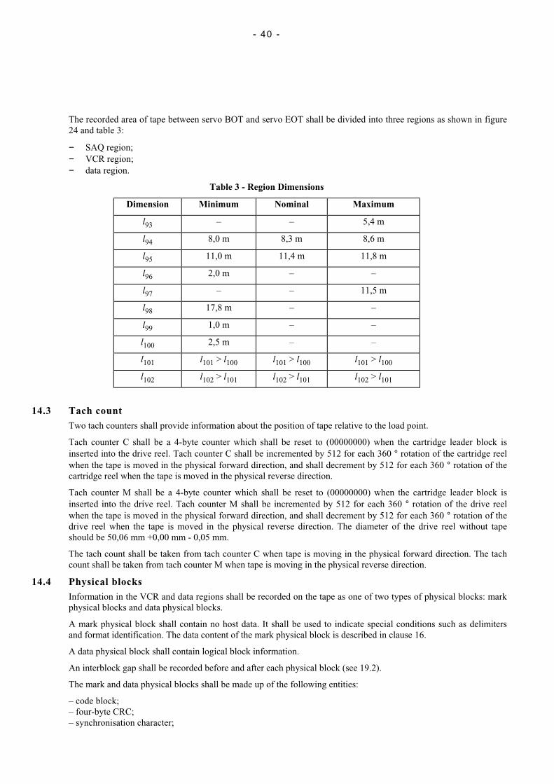
Servo tracks
Servo tracks
Servo tracks
Data region
SAQregion
VCRregion
l94
l93
l95
l96
l100
l101
l102
Reference edge of the tape l99 l97
l98
Leader block attachment point
Servo BOTBVCRBOT
EVCR
LP1BOP
LP3 ELEOP
Tape to hub junction
Servo EOT
EOT
LP2LEOP
98-0033-A
Figure 24 - Regions On Tape
- 40 -
The recorded area of tape between servo BOT and servo EOT shall be divided into three regions as shown in figure24 and table 3:
− SAQ region;− VCR region;− data region.
Table 3 - Region Dimensions
Dimension Minimum Nominal Maximum
l93 – – 5,4 m
l94 8,0 m 8,3 m 8,6 m
l95 11,0 m 11,4 m 11,8 m
l96 2,0 m – –
l97 – – 11,5 m
l98 17,8 m – –
l99 1,0 m – –
l100 2,5 m – –
l101 l101 > l100 l101 > l100 l101 > l100
l102 l102 > l101 l102 > l101 l102 > l101
14.3 Tach countTwo tach counters shall provide information about the position of tape relative to the load point.
Tach counter C shall be a 4-byte counter which shall be reset to (00000000) when the cartridge leader block isinserted into the drive reel. Tach counter C shall be incremented by 512 for each 360 ° rotation of the cartridge reelwhen the tape is moved in the physical forward direction, and shall decrement by 512 for each 360 ° rotation of thecartridge reel when the tape is moved in the physical reverse direction.
Tach counter M shall be a 4-byte counter which shall be reset to (00000000) when the cartridge leader block isinserted into the drive reel. Tach counter M shall be incremented by 512 for each 360 ° rotation of the drive reelwhen the tape is moved in the physical forward direction, and shall decrement by 512 for each 360 ° rotation of thedrive reel when the tape is moved in the physical reverse direction. The diameter of the drive reel without tapeshould be 50,06 mm +0,00 mm - 0,05 mm.
The tach count shall be taken from tach counter C when tape is moving in the physical forward direction. The tachcount shall be taken from tach counter M when tape is moving in the physical reverse direction.
14.4 Physical blocksInformation in the VCR and data regions shall be recorded on the tape as one of two types of physical blocks: markphysical blocks and data physical blocks.
A mark physical block shall contain no host data. It shall be used to indicate special conditions such as delimitersand format identification. The data content of the mark physical block is described in clause 16.
A data physical block shall contain logical block information.
An interblock gap shall be recorded before and after each physical block (see 19.2).
The mark and data physical blocks shall be made up of the following entities:
– code block;– four-byte CRC;– synchronisation character;
- 41 -
– resynchronisation burst;– acquisition burst;– synchronisation burst interval;– modulation triplet;– modulation character.
14.5 Servo acquisition regionThe servo acquisition region (SAQ) is used by the track following servo. The servo track format is described inclause 12. The servo acquisition region shall not contain recorded data information.
14.6 Volume control regionThe volume control region (VCR) shall be located at the beginning of half-wrap 0 immediately following the servoacquisition region (SAQ). The VCR shall contain the following marks:
− Format identification (FID) mark: The FID mark shall be the first entity recorded on the tape. The FID shallidentify the format that was used to write the data area of the physical volume. The FID shall also be thereference point from which distance along the tape is measured.
− Device block map (DBM) mark: The DBM mark shall immediately follow the FID mark and shall containinformation which may be written and used by the system to determine the location of the partition, mediadefects, and recorded elements.
− Statistical analysis and reporting system (SARS) mark: The SARS mark shall immediately follow the DBMmark.
− DBM Valid mark: The DBM Valid mark, if present, shall immediately follow the SARS mark. The presence ofthe DBM valid mark shall indicate that the DBM mark is valid. When a cartridge is opened, this mark shall beoverwritten by the DBM Checked Out mark.
− DBM Checked Out mark: The DBM Checked Out mark, if present, shall immediately follow the SARS mark.The presence of the DBM Checked Out mark shall indicate that the DBM mark is not valid. When the cartridgeis closed, this mark shall be overwritten by the DBM Valid mark if the information in the DBM is accurate.
14.7 Data regionThe data region shall be the portion of tape used to record data and marks. Nominally, it shall be located betweenlogical point 1 and logical point 2 for the physical forward half-wraps, and between logical point 2 and logical point3 for the physical reverse half-wraps.
All data and marks associated with the data region shall be contained within the area bounded by BOP and EOD.The data region shall contain the following entities:
– data physical block; – SDM mark;– BOP mark; – File Mark– BOW mark; – Void mark;– EOW mark; – IBG.– EOD mark;
14.8 Data entitiesData to be recorded shall be sent from a host computer to the drive in the form of logical blocks. See figure 25. Themaximum logical block size shall be 2 097 152 bytes. A 4-byte CRC shall be appended to each logical blockcreating a protected logical block.
Protected logical blocks shall be broken into sub-blocks.
− If a protected logical block contains 229 380 bytes or less, then a single sub-block equal in size to the protectedlogical block shall be created.
− If a protected logical block contains more than 229 380 bytes, sub-blocks shall be created as required for thenumber of bytes in the protected logical block. Each sub-block of that protected logical block, except the lastsub-block, shall contain 229 376 bytes. The last sub-block shall contain between 1 byte and 229 380 bytes.
All sub-blocks from one logical block shall be processed or unprocessed.
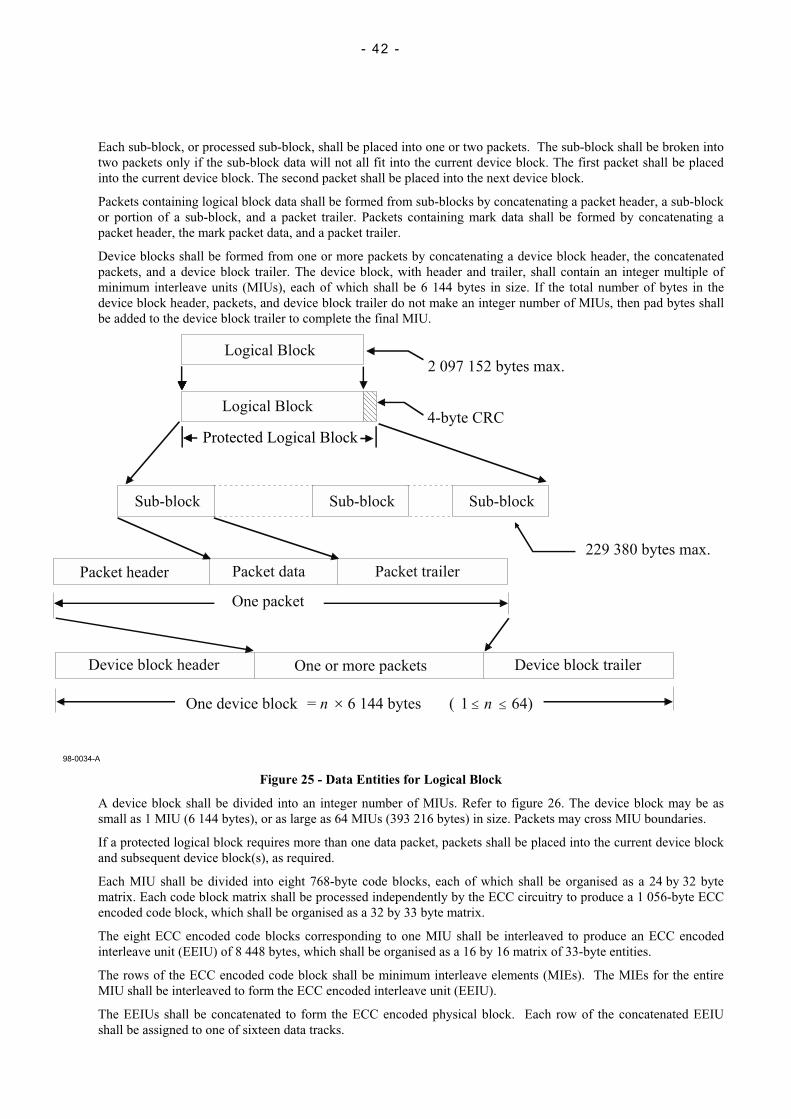
- 42 -
Each sub-block, or processed sub-block, shall be placed into one or two packets. The sub-block shall be broken intotwo packets only if the sub-block data will not all fit into the current device block. The first packet shall be placedinto the current device block. The second packet shall be placed into the next device block.
Packets containing logical block data shall be formed from sub-blocks by concatenating a packet header, a sub-blockor portion of a sub-block, and a packet trailer. Packets containing mark data shall be formed by concatenating apacket header, the mark packet data, and a packet trailer.
Device blocks shall be formed from one or more packets by concatenating a device block header, the concatenatedpackets, and a device block trailer. The device block, with header and trailer, shall contain an integer multiple ofminimum interleave units (MIUs), each of which shall be 6 144 bytes in size. If the total number of bytes in thedevice block header, packets, and device block trailer do not make an integer number of MIUs, then pad bytes shallbe added to the device block trailer to complete the final MIU.
Figure 25 - Data Entities for Logical Block
A device block shall be divided into an integer number of MIUs. Refer to figure 26. The device block may be assmall as 1 MIU (6 144 bytes), or as large as 64 MIUs (393 216 bytes) in size. Packets may cross MIU boundaries.
If a protected logical block requires more than one data packet, packets shall be placed into the current device blockand subsequent device block(s), as required.
Each MIU shall be divided into eight 768-byte code blocks, each of which shall be organised as a 24 by 32 bytematrix. Each code block matrix shall be processed independently by the ECC circuitry to produce a 1 056-byte ECCencoded code block, which shall be organised as a 32 by 33 byte matrix.
The eight ECC encoded code blocks corresponding to one MIU shall be interleaved to produce an ECC encodedinterleave unit (EEIU) of 8 448 bytes, which shall be organised as a 16 by 16 matrix of 33-byte entities.
The rows of the ECC encoded code block shall be minimum interleave elements (MIEs). The MIEs for the entireMIU shall be interleaved to form the ECC encoded interleave unit (EEIU).
The EEIUs shall be concatenated to form the ECC encoded physical block. Each row of the concatenated EEIUshall be assigned to one of sixteen data tracks.
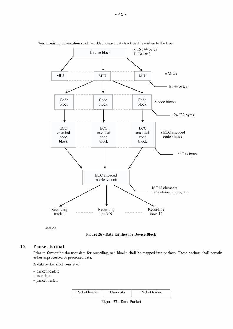
- 43 -
Synchronising information shall be added to each data track as it is written to the tape.
MIU
98-0035-A
MIU MIU
Codeblock
Codeblock
Codeblock
ECCencoded
codeblock
ECCencoded
codeblock
ECCencoded
codeblock
ECC encodedinterleave unit
Recordingtrack 1
Recordingtrack N
Recordingtrack 16
16 16 elementsEach element 33 bytes
32 33 bytes
8 ECC encodedcode blocks
24 32 bytes
8 code blocks
6 144 bytes
n MIUs
n
n
6 144 bytes(1 64)Device block
Figure 26 - Data Entities for Device Block
15 Packet formatPrior to formatting the user data for recording, sub-blocks shall be mapped into packets. These packets shall containeither unprocessed or processed data.
A data packet shall consist of:
– packet header;– user data;– packet trailer.
Packet header User data Packet trailer
Figure 27 - Data Packet

- 44 -
Prior to formatting marks for recording, the marks shall be mapped into packets. These packets shall containunprocessed mark data.
A mark packet shall consist of:
− packet header;− unprocessed mark data;− packet trailer.
In both types of packet, the bytes of the packet shall be numbered consecutively, starting with 0 for the first byte of thepacket header.
Packet header Mark data Packet trailer
Figure 28 - Mark Packet
15.1 Packet headerA 32-byte packet header shall be the first bytes of the packet. Packet header bytes shall not be processed.
− Byte 0: This byte shall be set to (00).
− Bytes 1 to 3: These bytes shall be set to the sequential number of the first byte of the Packet Trailer within thepacket.
− Bytes 4 to 7: These bytes shall be set to the logical block identifier. The logical block identifier shall be set to(00 00 00 00) for the first logical block within a partition. The logical block identifier shall be incremented by 1for each subsequent logical block within a partition.
If byte 10 is set to (FF), these bytes shall be set to the logical block identifier of the logical block which is fullyor partially recorded in the packet.
If byte 10 is set to (F0), these bytes shall be set to the logical block identifier of the File Mark.
If byte 10 is set to a value other than (FF) or (F0), these bytes shall be set to (FF).
− Byte 8: Packet control flags 1: This byte shall be set to (00).
− Byte 9: Packet control flags 2:
For packet type (FF) :
Bit 0: This bit shall be set to:
ZERO if this is not the last packet header in the current device block;ONE if this is the last packet header in the current device block.
Bit 1: This bit shall be set to ZERO.
Bit 2: The setting of this bit is not specified by this ECMA Standard, it shall be ignored in interchange.
Bit 3: This bit shall be set to:
ZERO if the data in the packet data field was not processed;ONE if the data in the packet data field was processed.
Bit 4: This bit shall be set to:
ZERO if the data in the packet data field does not contain all or part of the final sub-block of a logical block;ONE if the data in the packet data field contains all or part of the final sub-block of a logical block.
Bit 5: This bit shall be set to:
ZERO if the data in the packet data field does not contain all or part of the first sub-block of a logical block;ONE if the data in the packet data field contains all or part of the first sub-block of a logical block.
Bit 6: This bit shall be set to:
ZERO if the data in the packet data field does not contain the end of a sub-block; ONE if the data in the packetdata field contains the end of a sub-block.
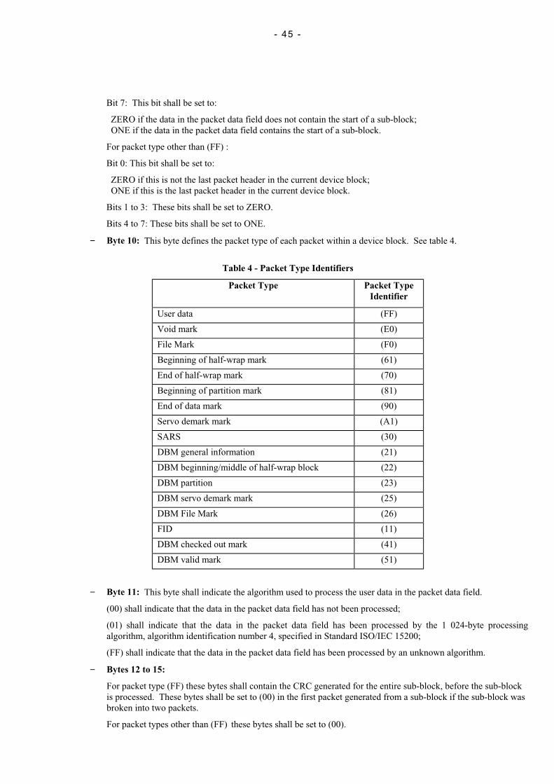
- 45 -
Bit 7: This bit shall be set to:
ZERO if the data in the packet data field does not contain the start of a sub-block;ONE if the data in the packet data field contains the start of a sub-block.
For packet type other than (FF) :
Bit 0: This bit shall be set to:
ZERO if this is not the last packet header in the current device block;ONE if this is the last packet header in the current device block.
Bits 1 to 3: These bits shall be set to ZERO.
Bits 4 to 7: These bits shall be set to ONE.
− Byte 10: This byte defines the packet type of each packet within a device block. See table 4.
Table 4 - Packet Type Identifiers
Packet Type Packet TypeIdentifier
User data (FF)
Void mark (E0)
File Mark (F0)
Beginning of half-wrap mark (61)
End of half-wrap mark (70)
Beginning of partition mark (81)
End of data mark (90)
Servo demark mark (A1)
SARS (30)
DBM general information (21)
DBM beginning/middle of half-wrap block (22)
DBM partition (23)
DBM servo demark mark (25)
DBM File Mark (26)
FID (11)
DBM checked out mark (41)
DBM valid mark (51)
− Byte 11: This byte shall indicate the algorithm used to process the user data in the packet data field.
(00) shall indicate that the data in the packet data field has not been processed;
(01) shall indicate that the data in the packet data field has been processed by the 1 024-byte processingalgorithm, algorithm identification number 4, specified in Standard ISO/IEC 15200;
(FF) shall indicate that the data in the packet data field has been processed by an unknown algorithm.
− Bytes 12 to 15:
For packet type (FF) these bytes shall contain the CRC generated for the entire sub-block, before the sub-blockis processed. These bytes shall be set to (00) in the first packet generated from a sub-block if the sub-block wasbroken into two packets.
For packet types other than (FF) these bytes shall be set to (00).
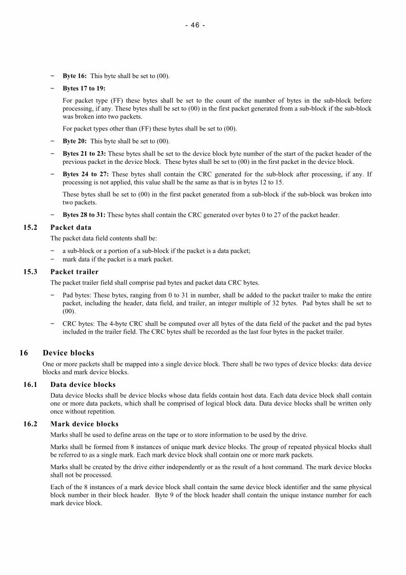
- 46 -
− Byte 16: This byte shall be set to (00).
− Bytes 17 to 19:
For packet type (FF) these bytes shall be set to the count of the number of bytes in the sub-block beforeprocessing, if any. These bytes shall be set to (00) in the first packet generated from a sub-block if the sub-blockwas broken into two packets.
For packet types other than (FF) these bytes shall be set to (00).
− Byte 20: This byte shall be set to (00).
− Bytes 21 to 23: These bytes shall be set to the device block byte number of the start of the packet header of theprevious packet in the device block. These bytes shall be set to (00) in the first packet in the device block.
− Bytes 24 to 27: These bytes shall contain the CRC generated for the sub-block after processing, if any. Ifprocessing is not applied, this value shall be the same as that is in bytes 12 to 15.
These bytes shall be set to (00) in the first packet generated from a sub-block if the sub-block was broken intotwo packets.
− Bytes 28 to 31: These bytes shall contain the CRC generated over bytes 0 to 27 of the packet header.
15.2 Packet dataThe packet data field contents shall be:
− a sub-block or a portion of a sub-block if the packet is a data packet;− mark data if the packet is a mark packet.
15.3 Packet trailerThe packet trailer field shall comprise pad bytes and packet data CRC bytes.
− Pad bytes: These bytes, ranging from 0 to 31 in number, shall be added to the packet trailer to make the entirepacket, including the header, data field, and trailer, an integer multiple of 32 bytes. Pad bytes shall be set to(00).
− CRC bytes: The 4-byte CRC shall be computed over all bytes of the data field of the packet and the pad bytesincluded in the trailer field. The CRC bytes shall be recorded as the last four bytes in the packet trailer.
16 Device blocksOne or more packets shall be mapped into a single device block. There shall be two types of device blocks: data deviceblocks and mark device blocks.
16.1 Data device blocksData device blocks shall be device blocks whose data fields contain host data. Each data device block shall containone or more data packets, which shall be comprised of logical block data. Data device blocks shall be written onlyonce without repetition.
16.2 Mark device blocksMarks shall be used to define areas on the tape or to store information to be used by the drive.
Marks shall be formed from 8 instances of unique mark device blocks. The group of repeated physical blocks shallbe referred to as a single mark. Each mark device block shall contain one or more mark packets.
Marks shall be created by the drive either independently or as the result of a host command. The mark device blocksshall not be processed.
Each of the 8 instances of a mark device block shall contain the same device block identifier and the same physicalblock number in their block header. Byte 9 of the block header shall contain the unique instance number for eachmark device block.

- 47 -
There shall be 12 mark types:
– File Mark; – SDM;
– Void; – FID;
– BOW; – SARS;
– EOW; – DBM;
– BOP; – DBM Checked Out;
– EOD; – DBM Valid.
16.3 File MarkThe File Mark shall be written to denote the end of a file or aggregate.
The File Mark device block shall contain one packet with 28 bytes of data, all of which shall be set to (00).
16.4 Void markUpon receipt of a host erase command, Void marks shall be written from the current position to the end of thecurrent partition.
The Void mark device block shall contain one packet with 28 bytes of data, all of which shall be set to (00).
16.5 Beginning of half-wrap markThe beginning of half-wrap mark (BOW) shall be written at the beginning of each half-wrap with the exception ofhalf-wrap 0 and any other half-wrap that coincides with the beginning of a partition.
The BOW mark device block shall contain one packet with 28 bytes of data which shall be set as follows:
− Bytes 0 to 2: These bytes shall be set to (00).
− Bytes 3 to 11: These bytes shall be set to the values that are contained in bytes 11 to 19 of the correspondingEOW mark block sequence control field (See 17.1).
− Bytes 12 to 15: These bytes shall contain the tach offset. The tach offset shall be the value computed bysubtracting the mark tach count of the previous EOW mark from the mark tach count of this BOW mark. Thetach offset shall be stored as a two's-complement signed value.
− Bytes 16 to 27: These bytes shall be set to (00).
16.6 End of half-wrap markThe end of half-wrap mark (EOW) shall be written at the end of a half-wrap that has been filled.
The EOW mark device block shall contain one packet with 28 bytes of data, all of which shall be set to (00).
If a half-wrap is not filled, then an EOD mark shall be written where writing of data stops and the EOW mark shallnot be written for that half-wrap.
On the final half-wrap of the volume, the EOW mark shall not be written. End of volume processing shall result inan EOD mark being written even if the half-wrap is full.
If a half-wrap ending coincides with an end of partition, then no EOW mark shall be written. End of partitionprocessing, which is equivalent to the end of volume processing, shall result in an EOD mark being written.
16.7 BOP markThe beginning of partition mark (BOP) shall define the beginning of the partition.
The BOP mark device block shall contain one packet with 28 bytes of data set to (00).
16.8 EOD markThe end of data mark (EOD) shall indicate that there is no more valid data in the current partition of the volume.
The EOD mark device block shall contain one packet with 28 bytes of data set to (00).
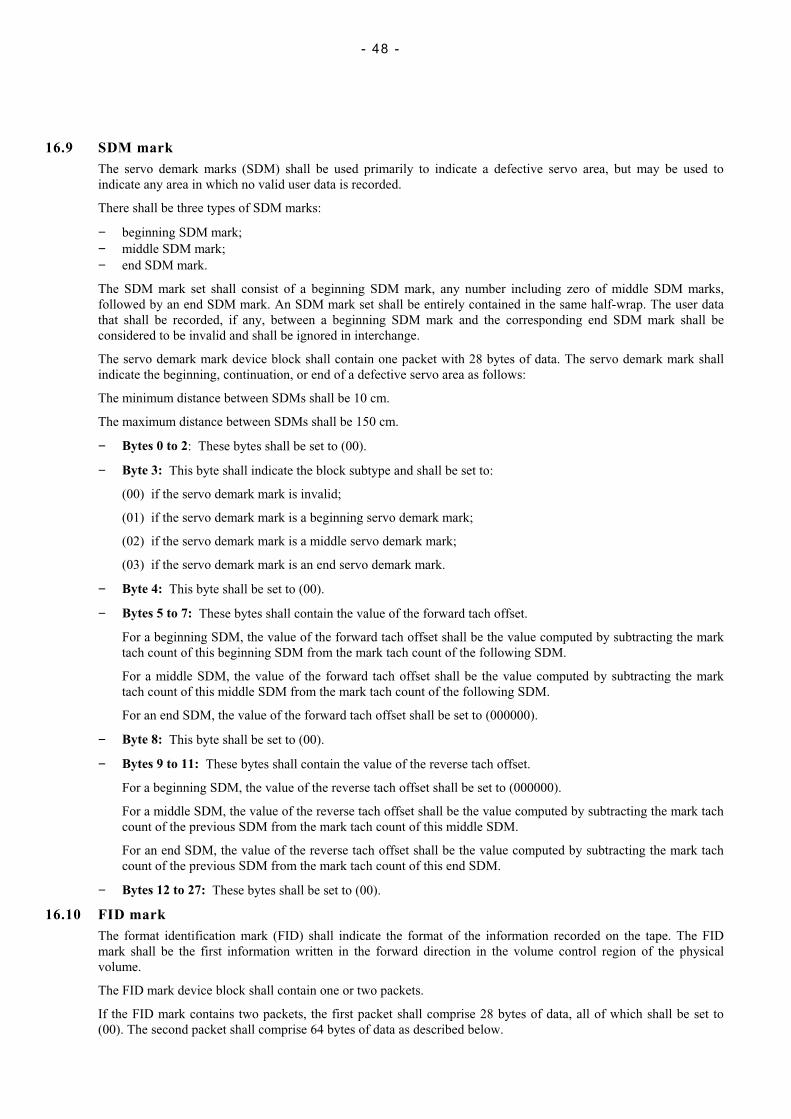
- 48 -
16.9 SDM markThe servo demark marks (SDM) shall be used primarily to indicate a defective servo area, but may be used toindicate any area in which no valid user data is recorded.
There shall be three types of SDM marks:
− beginning SDM mark;− middle SDM mark;− end SDM mark.
The SDM mark set shall consist of a beginning SDM mark, any number including zero of middle SDM marks,followed by an end SDM mark. An SDM mark set shall be entirely contained in the same half-wrap. The user datathat shall be recorded, if any, between a beginning SDM mark and the corresponding end SDM mark shall beconsidered to be invalid and shall be ignored in interchange.
The servo demark mark device block shall contain one packet with 28 bytes of data. The servo demark mark shallindicate the beginning, continuation, or end of a defective servo area as follows:
The minimum distance between SDMs shall be 10 cm.
The maximum distance between SDMs shall be 150 cm.
− Bytes 0 to 2: These bytes shall be set to (00).
− Byte 3: This byte shall indicate the block subtype and shall be set to:
(00) if the servo demark mark is invalid;
(01) if the servo demark mark is a beginning servo demark mark;
(02) if the servo demark mark is a middle servo demark mark;
(03) if the servo demark mark is an end servo demark mark.
− Byte 4: This byte shall be set to (00).
− Bytes 5 to 7: These bytes shall contain the value of the forward tach offset.
For a beginning SDM, the value of the forward tach offset shall be the value computed by subtracting the marktach count of this beginning SDM from the mark tach count of the following SDM.
For a middle SDM, the value of the forward tach offset shall be the value computed by subtracting the marktach count of this middle SDM from the mark tach count of the following SDM.
For an end SDM, the value of the forward tach offset shall be set to (000000).
− Byte 8: This byte shall be set to (00).
− Bytes 9 to 11: These bytes shall contain the value of the reverse tach offset.
For a beginning SDM, the value of the reverse tach offset shall be set to (000000).
For a middle SDM, the value of the reverse tach offset shall be the value computed by subtracting the mark tachcount of the previous SDM from the mark tach count of this middle SDM.
For an end SDM, the value of the reverse tach offset shall be the value computed by subtracting the mark tachcount of the previous SDM from the mark tach count of this end SDM.
− Bytes 12 to 27: These bytes shall be set to (00).
16.10 FID markThe format identification mark (FID) shall indicate the format of the information recorded on the tape. The FIDmark shall be the first information written in the forward direction in the volume control region of the physicalvolume.
The FID mark device block shall contain one or two packets.
If the FID mark contains two packets, the first packet shall comprise 28 bytes of data, all of which shall be set to(00). The second packet shall comprise 64 bytes of data as described below.
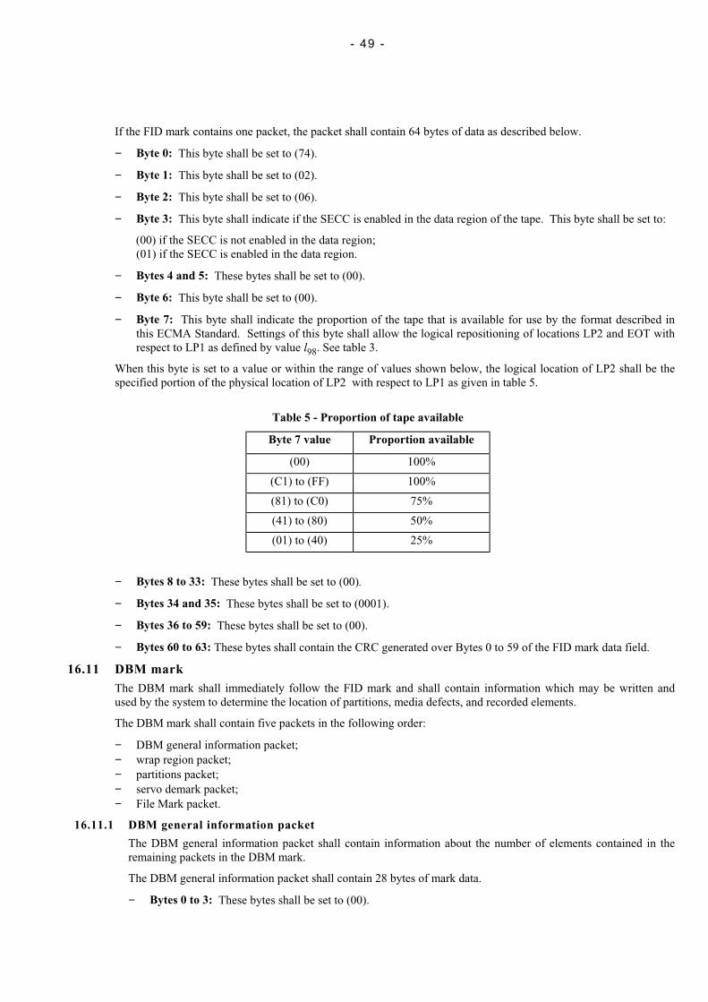
- 49 -
If the FID mark contains one packet, the packet shall contain 64 bytes of data as described below.
− Byte 0: This byte shall be set to (74).
− Byte 1: This byte shall be set to (02).
− Byte 2: This byte shall be set to (06).
− Byte 3: This byte shall indicate if the SECC is enabled in the data region of the tape. This byte shall be set to:
(00) if the SECC is not enabled in the data region;(01) if the SECC is enabled in the data region.
− Bytes 4 and 5: These bytes shall be set to (00).
− Byte 6: This byte shall be set to (00).
− Byte 7: This byte shall indicate the proportion of the tape that is available for use by the format described inthis ECMA Standard. Settings of this byte shall allow the logical repositioning of locations LP2 and EOT withrespect to LP1 as defined by value l98. See table 3.
When this byte is set to a value or within the range of values shown below, the logical location of LP2 shall be thespecified portion of the physical location of LP2 with respect to LP1 as given in table 5.
Table 5 - Proportion of tape available
Byte 7 value Proportion available
(00) 100%
(C1) to (FF) 100%
(81) to (C0) 75%
(41) to (80) 50%
(01) to (40) 25%
− Bytes 8 to 33: These bytes shall be set to (00).
− Bytes 34 and 35: These bytes shall be set to (0001).
− Bytes 36 to 59: These bytes shall be set to (00).
− Bytes 60 to 63: These bytes shall contain the CRC generated over Bytes 0 to 59 of the FID mark data field.
16.11 DBM markThe DBM mark shall immediately follow the FID mark and shall contain information which may be written andused by the system to determine the location of partitions, media defects, and recorded elements.
The DBM mark shall contain five packets in the following order:
− DBM general information packet;− wrap region packet;− partitions packet;− servo demark packet;− File Mark packet.
16.11.1 DBM general information packet
The DBM general information packet shall contain information about the number of elements contained in theremaining packets in the DBM mark.
The DBM general information packet shall contain 28 bytes of mark data.
− Bytes 0 to 3: These bytes shall be set to (00).
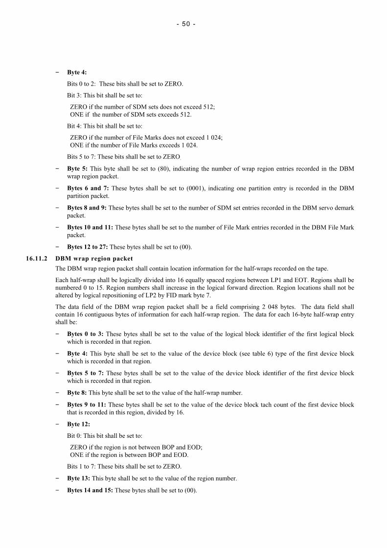
- 50 -
− Byte 4:
Bits 0 to 2: These bits shall be set to ZERO.
Bit 3: This bit shall be set to:
ZERO if the number of SDM sets does not exceed 512;ONE if the number of SDM sets exceeds 512.
Bit 4: This bit shall be set to:
ZERO if the number of File Marks does not exceed 1 024;ONE if the number of File Marks exceeds 1 024.
Bits 5 to 7: These bits shall be set to ZERO.
− Byte 5: This byte shall be set to (80), indicating the number of wrap region entries recorded in the DBMwrap region packet.
− Bytes 6 and 7: These bytes shall be set to (0001), indicating one partition entry is recorded in the DBMpartition packet.
− Bytes 8 and 9: These bytes shall be set to the number of SDM set entries recorded in the DBM servo demarkpacket.
− Bytes 10 and 11: These bytes shall be set to the number of File Mark entries recorded in the DBM File Markpacket.
− Bytes 12 to 27: These bytes shall be set to (00).
16.11.2 DBM wrap region packet
The DBM wrap region packet shall contain location information for the half-wraps recorded on the tape.
Each half-wrap shall be logically divided into 16 equally spaced regions between LP1 and EOT. Regions shall benumbered 0 to 15. Region numbers shall increase in the logical forward direction. Region locations shall not bealtered by logical repositioning of LP2 by FID mark byte 7.
The data field of the DBM wrap region packet shall be a field comprising 2 048 bytes. The data field shallcontain 16 contiguous bytes of information for each half-wrap region. The data for each 16-byte half-wrap entryshall be:
− Bytes 0 to 3: These bytes shall be set to the value of the logical block identifier of the first logical blockwhich is recorded in that region.
− Byte 4: This byte shall be set to the value of the device block (see table 6) type of the first device blockwhich is recorded in that region.
− Bytes 5 to 7: These bytes shall be set to the value of the device block identifier of the first device blockwhich is recorded in that region.
− Byte 8: This byte shall be set to the value of the half-wrap number.
− Bytes 9 to 11: These bytes shall be set to the value of the device block tach count of the first device blockthat is recorded in this region, divided by 16.
− Byte 12:
Bit 0: This bit shall be set to:
ZERO if the region is not between BOP and EOD;ONE if the region is between BOP and EOD.
Bits 1 to 7: These bits shall be set to ZERO.
− Byte 13: This byte shall be set to the value of the region number.
− Bytes 14 and 15: These bytes shall be set to (00).
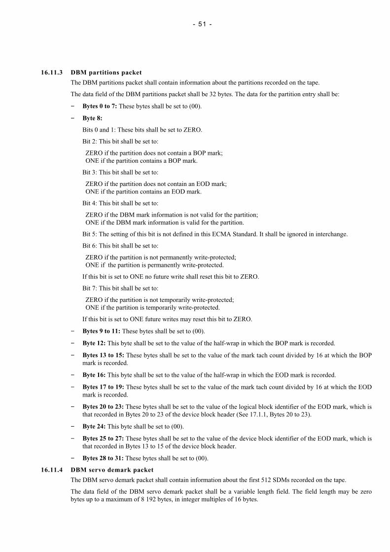
- 51 -
16.11.3 DBM partitions packet
The DBM partitions packet shall contain information about the partitions recorded on the tape.
The data field of the DBM partitions packet shall be 32 bytes. The data for the partition entry shall be:
− Bytes 0 to 7: These bytes shall be set to (00).
− Byte 8:
Bits 0 and 1: These bits shall be set to ZERO.
Bit 2: This bit shall be set to:
ZERO if the partition does not contain a BOP mark;ONE if the partition contains a BOP mark.
Bit 3: This bit shall be set to:
ZERO if the partition does not contain an EOD mark;ONE if the partition contains an EOD mark.
Bit 4: This bit shall be set to:
ZERO if the DBM mark information is not valid for the partition;ONE if the DBM mark information is valid for the partition.
Bit 5: The setting of this bit is not defined in this ECMA Standard. It shall be ignored in interchange.
Bit 6: This bit shall be set to:
ZERO if the partition is not permanently write-protected;ONE if the partition is permanently write-protected.
If this bit is set to ONE no future write shall reset this bit to ZERO.
Bit 7: This bit shall be set to:
ZERO if the partition is not temporarily write-protected;ONE if the partition is temporarily write-protected.
If this bit is set to ONE future writes may reset this bit to ZERO.
− Bytes 9 to 11: These bytes shall be set to (00).
− Byte 12: This byte shall be set to the value of the half-wrap in which the BOP mark is recorded.
− Bytes 13 to 15: These bytes shall be set to the value of the mark tach count divided by 16 at which the BOPmark is recorded.
− Byte 16: This byte shall be set to the value of the half-wrap in which the EOD mark is recorded.
− Bytes 17 to 19: These bytes shall be set to the value of the mark tach count divided by 16 at which the EODmark is recorded.
− Bytes 20 to 23: These bytes shall be set to the value of the logical block identifier of the EOD mark, which isthat recorded in Bytes 20 to 23 of the device block header (See 17.1.1, Bytes 20 to 23).
− Byte 24: This byte shall be set to (00).
− Bytes 25 to 27: These bytes shall be set to the value of the device block identifier of the EOD mark, which isthat recorded in Bytes 13 to 15 of the device block header.
− Bytes 28 to 31: These bytes shall be set to (00).
16.11.4 DBM servo demark packet
The DBM servo demark packet shall contain information about the first 512 SDMs recorded on the tape.
The data field of the DBM servo demark packet shall be a variable length field. The field length may be zerobytes up to a maximum of 8 192 bytes, in integer multiples of 16 bytes.
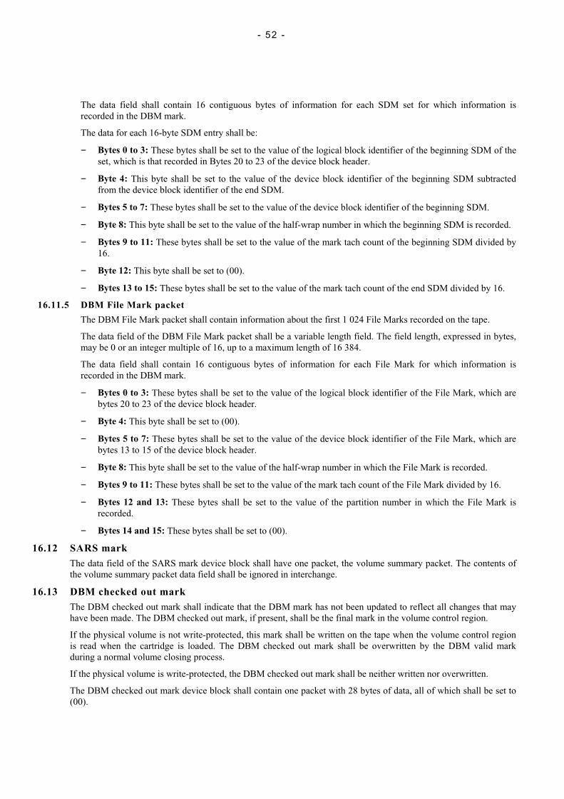
- 52 -
The data field shall contain 16 contiguous bytes of information for each SDM set for which information isrecorded in the DBM mark.
The data for each 16-byte SDM entry shall be:
− Bytes 0 to 3: These bytes shall be set to the value of the logical block identifier of the beginning SDM of theset, which is that recorded in Bytes 20 to 23 of the device block header.
− Byte 4: This byte shall be set to the value of the device block identifier of the beginning SDM subtractedfrom the device block identifier of the end SDM.
− Bytes 5 to 7: These bytes shall be set to the value of the device block identifier of the beginning SDM.
− Byte 8: This byte shall be set to the value of the half-wrap number in which the beginning SDM is recorded.
− Bytes 9 to 11: These bytes shall be set to the value of the mark tach count of the beginning SDM divided by16.
− Byte 12: This byte shall be set to (00).
− Bytes 13 to 15: These bytes shall be set to the value of the mark tach count of the end SDM divided by 16.
16.11.5 DBM File Mark packet
The DBM File Mark packet shall contain information about the first 1 024 File Marks recorded on the tape.
The data field of the DBM File Mark packet shall be a variable length field. The field length, expressed in bytes,may be 0 or an integer multiple of 16, up to a maximum length of 16 384.
The data field shall contain 16 contiguous bytes of information for each File Mark for which information isrecorded in the DBM mark.
− Bytes 0 to 3: These bytes shall be set to the value of the logical block identifier of the File Mark, which arebytes 20 to 23 of the device block header.
− Byte 4: This byte shall be set to (00).
− Bytes 5 to 7: These bytes shall be set to the value of the device block identifier of the File Mark, which arebytes 13 to 15 of the device block header.
− Byte 8: This byte shall be set to the value of the half-wrap number in which the File Mark is recorded.
− Bytes 9 to 11: These bytes shall be set to the value of the mark tach count of the File Mark divided by 16.
− Bytes 12 and 13: These bytes shall be set to the value of the partition number in which the File Mark isrecorded.
− Bytes 14 and 15: These bytes shall be set to (00).
16.12 SARS markThe data field of the SARS mark device block shall have one packet, the volume summary packet. The contents ofthe volume summary packet data field shall be ignored in interchange.
16.13 DBM checked out markThe DBM checked out mark shall indicate that the DBM mark has not been updated to reflect all changes that mayhave been made. The DBM checked out mark, if present, shall be the final mark in the volume control region.
If the physical volume is not write-protected, this mark shall be written on the tape when the volume control regionis read when the cartridge is loaded. The DBM checked out mark shall be overwritten by the DBM valid markduring a normal volume closing process.
If the physical volume is write-protected, the DBM checked out mark shall be neither written nor overwritten.
The DBM checked out mark device block shall contain one packet with 28 bytes of data, all of which shall be set to(00).
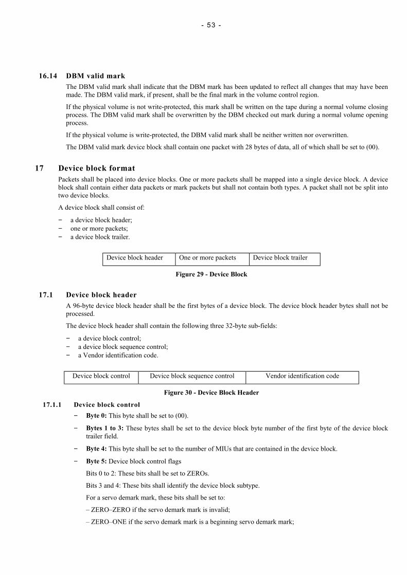
- 53 -
16.14 DBM valid markThe DBM valid mark shall indicate that the DBM mark has been updated to reflect all changes that may have beenmade. The DBM valid mark, if present, shall be the final mark in the volume control region.
If the physical volume is not write-protected, this mark shall be written on the tape during a normal volume closingprocess. The DBM valid mark shall be overwritten by the DBM checked out mark during a normal volume openingprocess.
If the physical volume is write-protected, the DBM valid mark shall be neither written nor overwritten.
The DBM valid mark device block shall contain one packet with 28 bytes of data, all of which shall be set to (00).
17 Device block formatPackets shall be placed into device blocks. One or more packets shall be mapped into a single device block. A deviceblock shall contain either data packets or mark packets but shall not contain both types. A packet shall not be split intotwo device blocks.
A device block shall consist of:
− a device block header;− one or more packets;− a device block trailer.
Device block header One or more packets Device block trailer
Figure 29 - Device Block
17.1 Device block headerA 96-byte device block header shall be the first bytes of a device block. The device block header bytes shall not beprocessed.
The device block header shall contain the following three 32-byte sub-fields:
− a device block control;− a device block sequence control;− a Vendor identification code.
Device block control Device block sequence control Vendor identification code
Figure 30 - Device Block Header
17.1.1 Device block control
− Byte 0: This byte shall be set to (00).
− Bytes 1 to 3: These bytes shall be set to the device block byte number of the first byte of the device blocktrailer field.
− Byte 4: This byte shall be set to the number of MIUs that are contained in the device block.
− Byte 5: Device block control flags
Bits 0 to 2: These bits shall be set to ZEROs.
Bits 3 and 4: These bits shall identify the device block subtype.
For a servo demark mark, these bits shall be set to:
– ZERO–ZERO if the servo demark mark is invalid;
– ZERO–ONE if the servo demark mark is a beginning servo demark mark;

- 54 -
– ONE–ZERO if the servo demark mark is a middle servo demark mark;
– ONE–ONE if the servo demark mark is an end servo demark mark.
For an end of data mark, the setting of these bits is not specified in this ECMA Standard. They shall beignored in interchange.
For all other marks, these bits shall be set to ZERO–ZERO.
Bit 5: This bit shall be set to ZERO.
Bit 6:
For device block type (FF) this bit shall be set to:
ZERO if the first packet in the device block data field contains the start of a sub-block; ONE if the firstpacket in the device block data field does not contain the start of a sub-block.
For device block types (60), (70), and (A0), this bit shall be set as bit 6 in the next device block.
For all other device block types this bit shall be set to ZERO.
Bit 7:
For device block type (FF) this bit shall be set to:
ZERO if the last packet in the device block data field contains the end of a sub-block; ONE if the last packetin the device block data field does not contain the end of a sub-block.
For device block type (60), (70), and (A0), this bit shall be set as bit 7 in the previous device block.
For all other device block types this bit shall be set to ZERO.
− Bytes 6 and 7: These bytes shall be set to the value of the number of packets within the device block datafield.
− Byte 8: This byte shall be set to (00) for a data device block, or to (07) for a mark device block.
− Byte 9: This byte shall be set to the value of the device block repetition.
For data device blocks this byte shall be set to (00).
For mark device blocks this byte shall be set to the number of the mark device block within the current mark.The number shall be set to 0 for the first mark device block within the mark, and shall be incremented by onefor each subsequent mark device block within the current mark.
− Byte 10: This field shall specify the type of packets within the device block. See table 6.
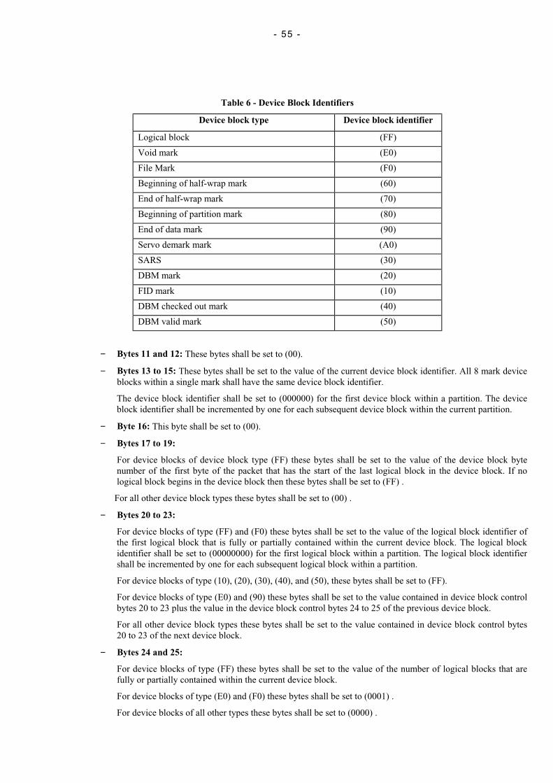
- 55 -
Table 6 - Device Block Identifiers
Device block type Device block identifier
Logical block (FF)
Void mark (E0)
File Mark (F0)
Beginning of half-wrap mark (60)
End of half-wrap mark (70)
Beginning of partition mark (80)
End of data mark (90)
Servo demark mark (A0)
SARS (30)
DBM mark (20)
FID mark (10)
DBM checked out mark (40)
DBM valid mark (50)
− Bytes 11 and 12: These bytes shall be set to (00).
− Bytes 13 to 15: These bytes shall be set to the value of the current device block identifier. All 8 mark deviceblocks within a single mark shall have the same device block identifier.
The device block identifier shall be set to (000000) for the first device block within a partition. The deviceblock identifier shall be incremented by one for each subsequent device block within the current partition.
− Byte 16: This byte shall be set to (00).
− Bytes 17 to 19:
For device blocks of device block type (FF) these bytes shall be set to the value of the device block bytenumber of the first byte of the packet that has the start of the last logical block in the device block. If nological block begins in the device block then these bytes shall be set to (FF) .
For all other device block types these bytes shall be set to (00) .
− Bytes 20 to 23:
For device blocks of type (FF) and (F0) these bytes shall be set to the value of the logical block identifier ofthe first logical block that is fully or partially contained within the current device block. The logical blockidentifier shall be set to (00000000) for the first logical block within a partition. The logical block identifiershall be incremented by one for each subsequent logical block within a partition.
For device blocks of type (10), (20), (30), (40), and (50), these bytes shall be set to (FF).
For device blocks of type (E0) and (90) these bytes shall be set to the value contained in device block controlbytes 20 to 23 plus the value in the device block control bytes 24 to 25 of the previous device block.
For all other device block types these bytes shall be set to the value contained in device block control bytes20 to 23 of the next device block.
− Bytes 24 and 25:
For device blocks of type (FF) these bytes shall be set to the value of the number of logical blocks that arefully or partially contained within the current device block.
For device blocks of type (E0) and (F0) these bytes shall be set to (0001) .
For device blocks of all other types these bytes shall be set to (0000) .
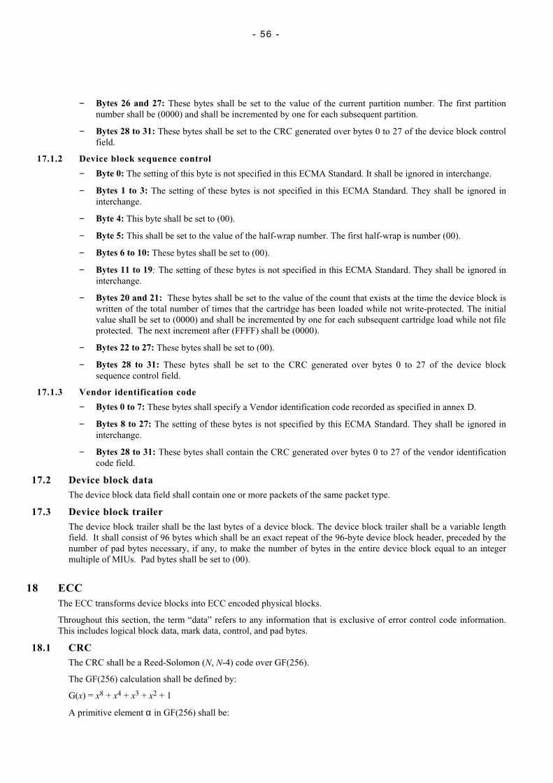
- 56 -
− Bytes 26 and 27: These bytes shall be set to the value of the current partition number. The first partitionnumber shall be (0000) and shall be incremented by one for each subsequent partition.
− Bytes 28 to 31: These bytes shall be set to the CRC generated over bytes 0 to 27 of the device block controlfield.
17.1.2 Device block sequence control
− Byte 0: The setting of this byte is not specified in this ECMA Standard. It shall be ignored in interchange.
− Bytes 1 to 3: The setting of these bytes is not specified in this ECMA Standard. They shall be ignored ininterchange.
− Byte 4: This byte shall be set to (00).
− Byte 5: This shall be set to the value of the half-wrap number. The first half-wrap is number (00).
− Bytes 6 to 10: These bytes shall be set to (00).
− Bytes 11 to 19: The setting of these bytes is not specified in this ECMA Standard. They shall be ignored ininterchange.
− Bytes 20 and 21: These bytes shall be set to the value of the count that exists at the time the device block iswritten of the total number of times that the cartridge has been loaded while not write-protected. The initialvalue shall be set to (0000) and shall be incremented by one for each subsequent cartridge load while not fileprotected. The next increment after (FFFF) shall be (0000).
− Bytes 22 to 27: These bytes shall be set to (00).
− Bytes 28 to 31: These bytes shall be set to the CRC generated over bytes 0 to 27 of the device blocksequence control field.
17.1.3 Vendor identification code
− Bytes 0 to 7: These bytes shall specify a Vendor identification code recorded as specified in annex D.
− Bytes 8 to 27: The setting of these bytes is not specified by this ECMA Standard. They shall be ignored ininterchange.
− Bytes 28 to 31: These bytes shall contain the CRC generated over bytes 0 to 27 of the vendor identificationcode field.
17.2 Device block dataThe device block data field shall contain one or more packets of the same packet type.
17.3 Device block trailerThe device block trailer shall be the last bytes of a device block. The device block trailer shall be a variable lengthfield. It shall consist of 96 bytes which shall be an exact repeat of the 96-byte device block header, preceded by thenumber of pad bytes necessary, if any, to make the number of bytes in the entire device block equal to an integermultiple of MIUs. Pad bytes shall be set to (00).
18 ECCThe ECC transforms device blocks into ECC encoded physical blocks.
Throughout this section, the term “data” refers to any information that is exclusive of error control code information.This includes logical block data, mark data, control, and pad bytes.
18.1 CRCThe CRC shall be a Reed-Solomon (N, N-4) code over GF(256).
The GF(256) calculation shall be defined by:
G(x) = x8 + x4 + x3 + x2 + 1
A primitive element α in GF(256) shall be:
- 57 -
α = ( 0 0 0 0 0 0 1 0 )
α7 α6 α5 α4 α3 α2 α1 α0
The generator polynomial shall be:
G(x) = x4 + α201x3 + α246x2 + α201x + α0
The CRC bytes shall be generated by a generator circuit whose registers shall be set to ZEROs prior to beginningprocessing. See figure 31. Registers R0 to R3 are 8 bits wide. Data bytes shall be fed sequentially into the encoder.Then the contents of R3 shall be CRC3, that of R2 shall be CRC2, that of R1 shall be CRC1, and that of R0 shall beCRC0. When these CRC bytes are appended to data bytes or placed in any field, CRC3 shall be the first byteappended, followed by CRC2, CRC1, and then CRC0.
Figure 31 - CRC shift register
18.2 Code blockThe code block shall be the basic data unit which is processed by the ECC algorithm. The code block shall contain768 bytes organised as a 24 by 32 byte matrix. The bytes of the code block may be any combination of data, control,or pad bytes. Eight code blocks shall be constructed from each MIU.
The eight code blocks shall be filled by placing the first MIU byte into row 1, column 1 of the first code block. Byte24 shall be placed in row 24, column 1. Byte 25 shall be placed in row 1, column 2. The first code block shall befilled completely before any data is placed in the second code block. This shall result in the first byte of the MIUbeing placed in row 1, column 1 of the first code block, and the final byte of the MIU being placed in row 24,column 32 of the final code block.
18.3 ECC encoded code blockThe ECC encoded code block shall be the result of processing a code block by the ECC algorithm. The ECCencoded code block shall contain 1 056 bytes organised as a 32 by 33 matrix. See figure 32.
The ECC encoded code block shall be comprised of the following items:
− Minimum Interleave Element (MIE): An MIE shall be any one row of the ECC encoded code block;
− Codeword: A Codeword shall be any of the first 32 columns of the ECC encoded code block;
− MIE Pointer: The MIE Pointer shall be a column 33 of the ECC encoded code block
Rows 1 to 24 and columns 1 to 32 of the ECC encoded code block shall contain the code block bytes in the samerow and column positions that they occupy in the code block.
Each 24-byte column of the 32-column code block shall be passed through ECC circuitry to generate 8 correctioncode bytes, which shall be placed in rows 25 to 32 of the ECC encoded code block.
Each 32-byte row of the 32-row ECC encoded code block shall be passed through ECC circuitry to generate oneerror detection code byte, which shall be placed in column 33 of the ECC encoded code block.
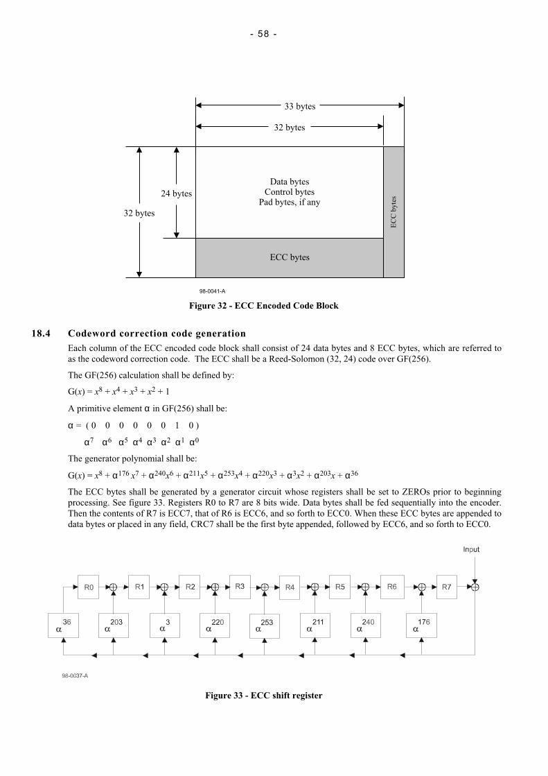
- 58 -
32 bytes
33 bytes
24 bytes
32 bytes
Data bytesControl bytes
Pad bytes, if any
ECC bytes
EC
Cb
yte
s
98-0041-A
Figure 32 - ECC Encoded Code Block
18.4 Codeword correction code generationEach column of the ECC encoded code block shall consist of 24 data bytes and 8 ECC bytes, which are referred toas the codeword correction code. The ECC shall be a Reed-Solomon (32, 24) code over GF(256).
The GF(256) calculation shall be defined by:
G(x) = x8 + x4 + x3 + x2 + 1
A primitive element α in GF(256) shall be:
α = ( 0 0 0 0 0 0 1 0 )
α7 α6 α5 α4 α3 α2 α1 α0
The generator polynomial shall be:
G(x) = x8 + α176 x7 + α240x6 + α211x5 + α253x4 + α220x3 + α3x2 + α203x + α36
The ECC bytes shall be generated by a generator circuit whose registers shall be set to ZEROs prior to beginningprocessing. See figure 33. Registers R0 to R7 are 8 bits wide. Data bytes shall be fed sequentially into the encoder.Then the contents of R7 is ECC7, that of R6 is ECC6, and so forth to ECC0. When these ECC bytes are appended todata bytes or placed in any field, CRC7 shall be the first byte appended, followed by ECC6, and so forth to ECC0.
Figure 33 - ECC shift register
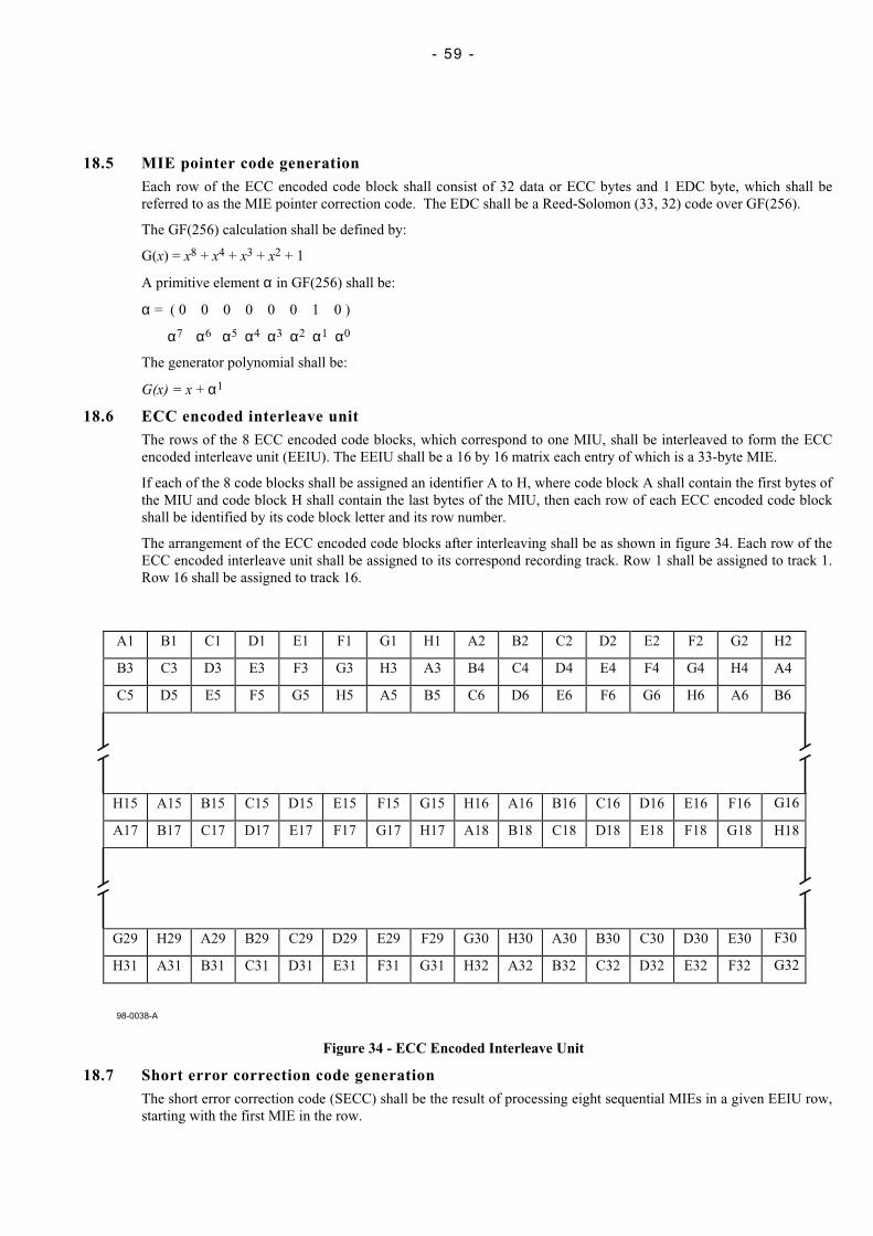
- 59 -
18.5 MIE pointer code generationEach row of the ECC encoded code block shall consist of 32 data or ECC bytes and 1 EDC byte, which shall bereferred to as the MIE pointer correction code. The EDC shall be a Reed-Solomon (33, 32) code over GF(256).
The GF(256) calculation shall be defined by:
G(x) = x8 + x4 + x3 + x2 + 1
A primitive element α in GF(256) shall be:
α = ( 0 0 0 0 0 0 1 0 )
α7 α6 α5 α4 α3 α2 α1 α0
The generator polynomial shall be:
G(x) = x + α1
18.6 ECC encoded interleave unitThe rows of the 8 ECC encoded code blocks, which correspond to one MIU, shall be interleaved to form the ECCencoded interleave unit (EEIU). The EEIU shall be a 16 by 16 matrix each entry of which is a 33-byte MIE.
If each of the 8 code blocks shall be assigned an identifier A to H, where code block A shall contain the first bytes ofthe MIU and code block H shall contain the last bytes of the MIU, then each row of each ECC encoded code blockshall be identified by its code block letter and its row number.
The arrangement of the ECC encoded code blocks after interleaving shall be as shown in figure 34. Each row of theECC encoded interleave unit shall be assigned to its correspond recording track. Row 1 shall be assigned to track 1.Row 16 shall be assigned to track 16.
A1 B1 C1 D1 E1 F1 G1 H1 A2 B2 C2 D2 E2 F2 G2
B3 C3 D3 E3 F3 G3 H3 A3 B4 C4 D4 E4 F4 G4 H4
C5 D5 E5 F5 G5 H5 A5 B5 C6 D6 E6 F6 G6 H6 A6
H15 A15 B15 C15 D15 E15 F15 G15 H16 A16 B16 C16 D16 E16 F16
A17 B17 C17 D17 E17 F17 G17 H17 A18 B18 C18 D18 E18 F18 G18
G29 H29 A29 B29 C29 D29 E29 F29 G30 H30 A30 B30 C30 D30 E30
H31 A31 B31 C31 D31 E31 F31 G31 H32 A32 B32 C32 D32 E32 F32
H2
A4
B6
G16
H18
F30
G32
98-0038-A
Figure 34 - ECC Encoded Interleave Unit
18.7 Short error correction code generationThe short error correction code (SECC) shall be the result of processing eight sequential MIEs in a given EEIU row,starting with the first MIE in the row.
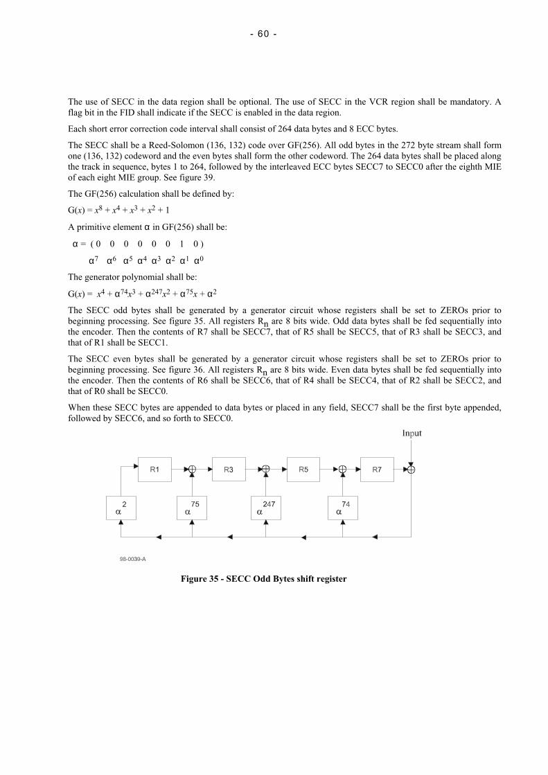
- 60 -
The use of SECC in the data region shall be optional. The use of SECC in the VCR region shall be mandatory. Aflag bit in the FID shall indicate if the SECC is enabled in the data region.
Each short error correction code interval shall consist of 264 data bytes and 8 ECC bytes.
The SECC shall be a Reed-Solomon (136, 132) code over GF(256). All odd bytes in the 272 byte stream shall formone (136, 132) codeword and the even bytes shall form the other codeword. The 264 data bytes shall be placed alongthe track in sequence, bytes 1 to 264, followed by the interleaved ECC bytes SECC7 to SECC0 after the eighth MIEof each eight MIE group. See figure 39.
The GF(256) calculation shall be defined by:
G(x) = x8 + x4 + x3 + x2 + 1
A primitive element α in GF(256) shall be:
α = ( 0 0 0 0 0 0 1 0 )
α7 α6 α5 α4 α3 α2 α1 α0
The generator polynomial shall be:
G(x) = x4 + α74x3 + α247x2 + α75x + α2
The SECC odd bytes shall be generated by a generator circuit whose registers shall be set to ZEROs prior tobeginning processing. See figure 35. All registers Rn are 8 bits wide. Odd data bytes shall be fed sequentially intothe encoder. Then the contents of R7 shall be SECC7, that of R5 shall be SECC5, that of R3 shall be SECC3, andthat of R1 shall be SECC1.
The SECC even bytes shall be generated by a generator circuit whose registers shall be set to ZEROs prior tobeginning processing. See figure 36. All registers Rn are 8 bits wide. Even data bytes shall be fed sequentially intothe encoder. Then the contents of R6 shall be SECC6, that of R4 shall be SECC4, that of R2 shall be SECC2, andthat of R0 shall be SECC0.
When these SECC bytes are appended to data bytes or placed in any field, SECC7 shall be the first byte appended,followed by SECC6, and so forth to SECC0.
Figure 35 - SECC Odd Bytes shift register
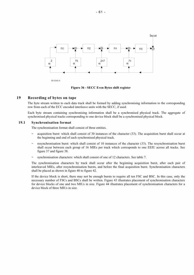
- 61 -
Figure 36 - SECC Even Bytes shift register
19 Recording of bytes on tapeThe byte stream written to each data track shall be formed by adding synchronising information to the correspondingrow from each of the ECC encoded interleave units with the SECC, if used.
Each byte stream containing synchronising information shall be a synchronised physical track. The aggregate ofsynchronised physical tracks corresponding to one device block shall be a synchronised physical block.
19.1 Synchronisation formatThe synchronisation format shall consist of three entities.
− acquisition burst: which shall consist of 30 instances of the character (33). The acquisition burst shall occur atthe beginning and end of each synchronised physical track.
− resynchronisation burst: which shall consist of 10 instances of the character (33). The resynchronisation burstshall occur between each group of 16 MIEs per track which corresponds to one EEIU across all tracks. Seefigure 37 and figure 38.
− synchronisation characters: which shall consist of one of 12 characters. See table 7.
The synchronisation characters by track shall occur after the beginning acquisition burst, after each pair ofinterleaved MIEs, after resynchronisation bursts, and before the final acquisition burst. Synchronisation charactersshall be placed as shown in figure 40 to figure 42.
If the device block is short, there may not be enough bursts to require all ten FSC and BSC. In this case, only thenecessary number of FSCs and BSCs shall be written. Figure 43 illustrates placement of synchronisation charactersfor device blocks of one and two MIUs in size. Figure 44 illustrates placement of synchronisation characters for adevice block of three MIUs in size.
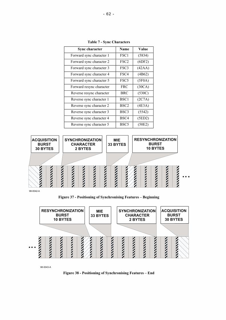
- 62 -
Table 7 - Sync Characters
Sync character Name Value
Forward sync character 1 FSC1 (5834)
Forward sync character 2 FSC2 (6DF2)
Forward sync character 3 FSC3 (42AA)
Forward sync character 4 FSC4 (4B62)
Forward sync character 5 FSC5 (5F0A)
Forward resync character FRC (30CA)
Reverse resync character BRC (530C)
Reverse sync character 1 BSC1 (2C7A)
Reverse sync character 2 BSC2 (4E3A)
Reverse sync character 3 BSC3 (5542)
Reverse sync character 4 BSC4 (5ED2)
Reverse sync character 5 BSC5 (50E2)
ACQUISITION
BURST
30 BYTES
SYNCHRONIZATION
CHARACTER
2 BYTES
MIE
33 BYTES
RESYNCHRONIZATION
BURST
10 BYTES
98-0042-A
Figure 37 - Positioning of Synchronising Features – Beginning
ACQUISITION
BURST
30 BYTES
SYNCHRONIZATION
CHARACTER
2 BYTES
MIE
33 BYTES
RESYNCHRONIZATION
BURST
10 BYTES
98-0043-A
Figure 38 - Positioning of Synchronising Features – End
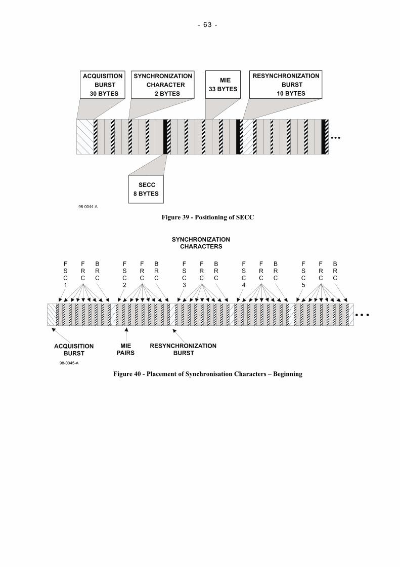
- 63 -
98-0044-A
ACQUISITION
BURST
30 BYTES
SYNCHRONIZATION
CHARACTER
2 BYTES
MIE
33 BYTES
RESYNCHRONIZATION
BURST
10 BYTES
SECC
8 BYTES
Figure 39 - Positioning of SECC
ACQUISITION
BURST
SYNCHRONIZATION
CHARACTERS
MIE
PAIRS
RESYNCHRONIZATION
BURST
F
S
C
1
B
R
C
F
R
C
F
S
C
2
B
R
C
F
R
C
F
S
C
3
B
R
C
F
R
C
F
S
C
4
B
R
C
F
R
C
F
S
C
5
B
R
C
F
R
C
98-0045-A
Figure 40 - Placement of Synchronisation Characters – Beginning
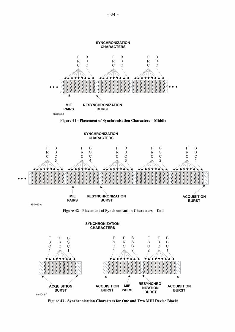
- 64 -
SYNCHRONIZATION
CHARACTERS
MIE
PAIRS
RESYNCHRONIZATION
BURST
B
R
C
F
R
C
B
R
C
F
R
C
B
R
C
F
R
C
98-0046-A
Figure 41 - Placement of Synchronisation Characters – Middle
ACQUISITION
BURST
SYNCHRONIZATION
CHARACTERS
MIE
PAIRS
RESYNCHRONIZATION
BURST
B
S
C
5
F
R
C
B
S
C
4
F
R
C
B
S
C
3
F
R
C
B
S
C
2
F
R
C
B
S
C
1
F
R
C
98-0047-A
Figure 42 - Placement of Synchronisation Characters – End
ACQUISITION
BURST
SYNCHRONIZATION
CHARACTERS
F
S
C
1
B
S
C
1
F
R
C
ACQUISITION
BURST
MIE
PAIRS
F
S
C
1
B
S
C
2
F
R
C
F
S
C
2
B
S
C
1
F
R
C
RESYNCHRO-
NIZATION
BURST
ACQUISITION
BURST
98-0048-A
Figure 43 - Synchronisation Characters for One and Two MIU Device Blocks
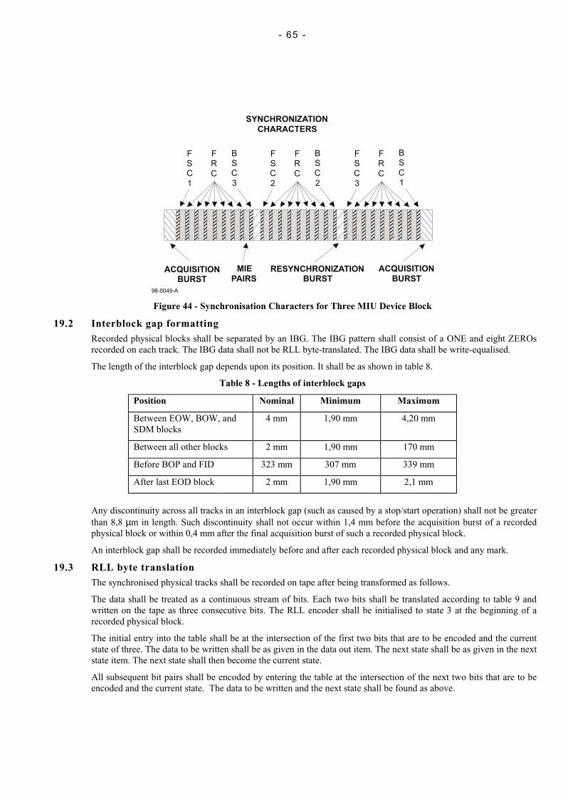
- 65 -
ACQUISITION
BURST
SYNCHRONIZATION
CHARACTERS
MIE
PAIRS
RESYNCHRONIZATION
BURST
F
S
C
1
B
S
C
3
F
R
C
F
S
C
2
B
S
C
2
F
R
C
F
S
C
3
B
S
C
1
F
R
C
ACQUISITION
BURST
98-0049-A
Figure 44 - Synchronisation Characters for Three MIU Device Block
19.2 Interblock gap formattingRecorded physical blocks shall be separated by an IBG. The IBG pattern shall consist of a ONE and eight ZEROsrecorded on each track. The IBG data shall not be RLL byte-translated. The IBG data shall be write-equalised.
The length of the interblock gap depends upon its position. It shall be as shown in table 8.
Table 8 - Lengths of interblock gaps
Position Nominal Minimum Maximum
Between EOW, BOW, andSDM blocks
4 mm 1,90 mm 4,20 mm
Between all other blocks 2 mm 1,90 mm 170 mm
Before BOP and FID 323 mm 307 mm 339 mm
After last EOD block 2 mm 1,90 mm 2,1 mm
Any discontinuity across all tracks in an interblock gap (such as caused by a stop/start operation) shall not be greaterthan 8,8 µm in length. Such discontinuity shall not occur within 1,4 mm before the acquisition burst of a recordedphysical block or within 0,4 mm after the final acquisition burst of such a recorded physical block.
An interblock gap shall be recorded immediately before and after each recorded physical block and any mark.
19.3 RLL byte translationThe synchronised physical tracks shall be recorded on tape after being transformed as follows.
The data shall be treated as a continuous stream of bits. Each two bits shall be translated according to table 9 andwritten on the tape as three consecutive bits. The RLL encoder shall be initialised to state 3 at the beginning of arecorded physical block.
The initial entry into the table shall be at the intersection of the first two bits that are to be encoded and the currentstate of three. The data to be written shall be as given in the data out item. The next state shall be as given in the nextstate item. The next state shall then become the current state.
All subsequent bit pairs shall be encoded by entering the table at the intersection of the next two bits that are to beencoded and the current state. The data to be written and the next state shall be found as above.
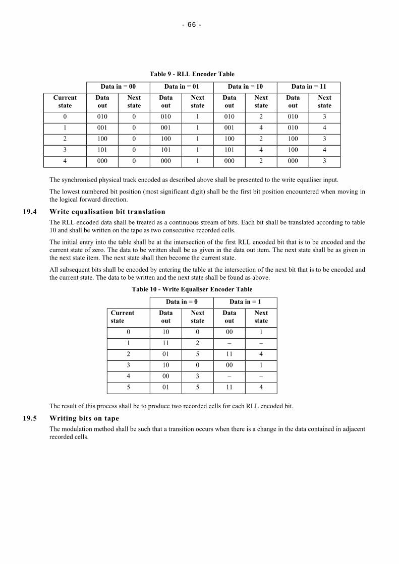
- 66 -
Table 9 - RLL Encoder Table
Data in = 00 Data in = 01 Data in = 10 Data in = 11
Currentstate
Dataout
Nextstate
Dataout
Nextstate
Dataout
Nextstate
Dataout
Nextstate
0 010 0 010 1 010 2 010 3
1 001 0 001 1 001 4 010 4
2 100 0 100 1 100 2 100 3
3 101 0 101 1 101 4 100 4
4 000 0 000 1 000 2 000 3
The synchronised physical track encoded as described above shall be presented to the write equaliser input.
The lowest numbered bit position (most significant digit) shall be the first bit position encountered when moving inthe logical forward direction.
19.4 Write equalisation bit translationThe RLL encoded data shall be treated as a continuous stream of bits. Each bit shall be translated according to table10 and shall be written on the tape as two consecutive recorded cells.
The initial entry into the table shall be at the intersection of the first RLL encoded bit that is to be encoded and thecurrent state of zero. The data to be written shall be as given in the data out item. The next state shall be as given inthe next state item. The next state shall then become the current state.
All subsequent bits shall be encoded by entering the table at the intersection of the next bit that is to be encoded andthe current state. The data to be written and the next state shall be found as above.
Table 10 - Write Equaliser Encoder Table
Data in = 0 Data in = 1
Currentstate
Dataout
Nextstate
Dataout
Nextstate
0 10 0 00 1
1 11 2 – –
2 01 5 11 4
3 10 0 00 1
4 00 3 – –
5 01 5 11 4
The result of this process shall be to produce two recorded cells for each RLL encoded bit.
19.5 Writing bits on tapeThe modulation method shall be such that a transition occurs when there is a change in the data contained in adjacentrecorded cells.
- 67 -
Annex A(normative)
Tape abrasivity measurement procedure
A.1 GeneralTape abrasivity is the tendency of the tape to wear the tape transport.
A.2 Test fixtureInstall a clean ferrite wear bar made as shown in figure A.1 on a holding fixture similar to that shown in figure A.2.Test edge facing upward shall be unworn and free of chips or voids greater than 1 µm in size. The radius of the testedge shall not exceed 13 µm.
The ferrite bar shall be composed of single-phase polycrystalline ferrite. It shall have the following weight percentages:
ZnO 22 %NiO 11 %Fe2O3 67 %
The average grain size shall be within 7 µm to 8 µm. Its density shall be 5,32 g/cm3.
The surface finish on all four sides of the bar shall be at least of roughness grade N2, 0,05 µm.
The wear bar shall be square within 0,05 mm.
A.3 ProcedureInstall the test fixture on a tape transport so that the wrap angle of the tape over the bar is 8 ° on each side, for 16 ° oftotal wrap;
Set the tape tension at the bar at 1,4 N.
With a tape speed of 1,0 m/s, make one pass of the tape over the wear bar. The length of tape passing over the wear barshall be 520 m ± 2,5 m. This length may be segmented into the appropriate number of cartridges.
Remove the holding fixture from the transport and measure the length of the flat worn on the wear bar. Thismeasurement is most easily made using a microscope of known magnification, a camera, and a reference reticule.Magnification of 300X or higher is recommended.
Measurements shall be taken at the 1/4, 1/2, and 3/4 points of the 12,65 mm width of the wear pattern. Take the averagelength calculated from the three readings. Figure A.3 shows a typical wear pattern and the points of measurements.
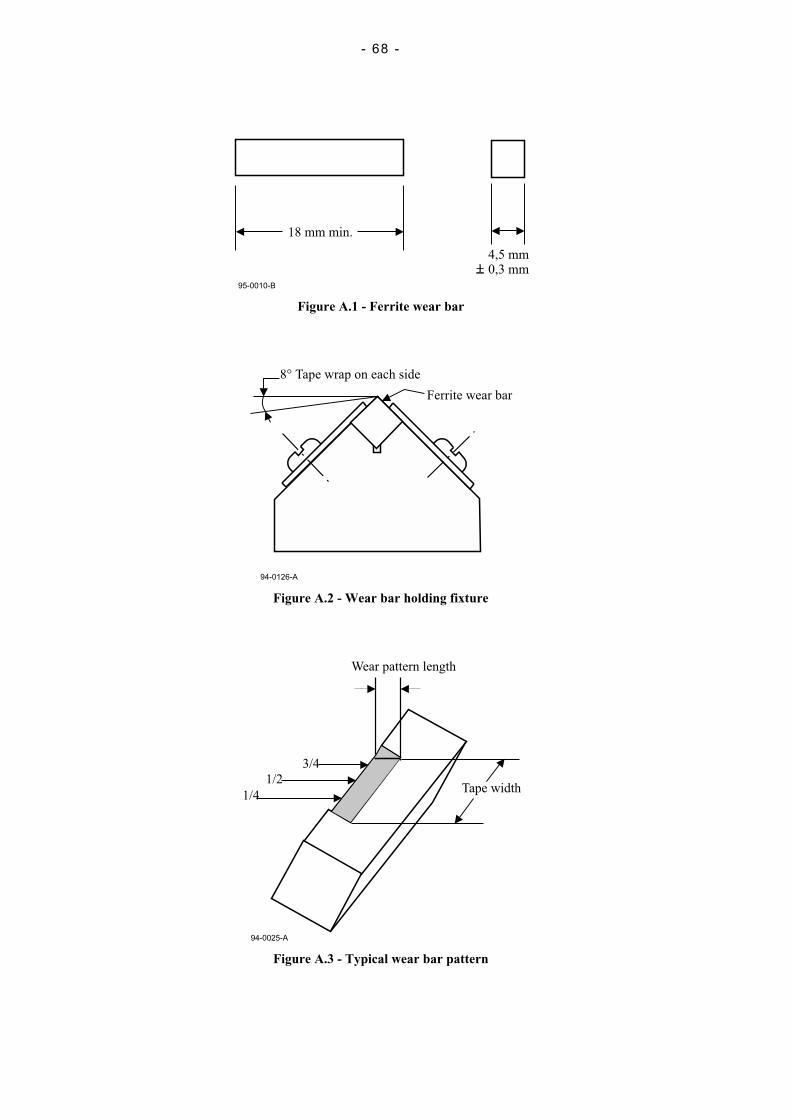
- 68 -
18 mm min.
4,5 mm0,3 mm
95-0010-B
Figure A.1 - Ferrite wear bar
8° Tape wrap on each side
Ferrite wear bar
94-0126-A
Figure A.2 - Wear bar holding fixture
94-0025-A
3/4
1/2
1/4Tape width
Wear pattern length
Figure A.3 - Typical wear bar pattern
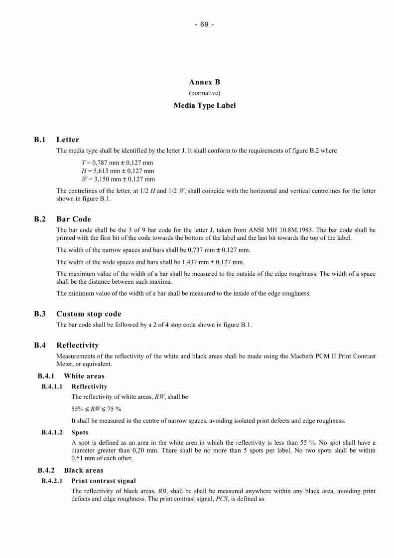
- 69 -
Annex B(normative)
Media Type Label
B.1 LetterThe media type shall be identified by the letter J. It shall conform to the requirements of figure B.2 where
T = 0,787 mm ± 0,127 mmH = 5,613 mm ± 0,127 mmW = 3,150 mm ± 0,127 mm
The centrelines of the letter, at 1/2 H and 1/2 W, shall coincide with the horizontal and vertical centrelines for the lettershown in figure B.1.
B.2 Bar CodeThe bar code shall be the 3 of 9 bar code for the letter J, taken from ANSI MH 10.8M.1983. The bar code shall beprinted with the first bit of the code towards the bottom of the label and the last bit towards the top of the label.
The width of the narrow spaces and bars shall be 0,737 mm ± 0,127 mm.
The width of the wide spaces and bars shall be 1,437 mm ± 0,127 mm.
The maximum value of the width of a bar shall be measured to the outside of the edge roughness. The width of a spaceshall be the distance between such maxima.
The minimum value of the width of a bar shall be measured to the inside of the edge roughness.
B.3 Custom stop codeThe bar code shall be followed by a 2 of 4 stop code shown in figure B.1.
B.4 ReflectivityMeasurements of the reflectivity of the white and black areas shall be made using the Macbeth PCM II Print ContrastMeter, or equivalent.
B.4.1 White areasB.4.1.1 Reflectivity
The reflectivity of white areas, RW, shall be
55% ≤ RW ≤ 75 %
It shall be measured in the centre of narrow spaces, avoiding isolated print defects and edge roughness.
B.4.1.2 Spots
A spot is defined as an area in the white area in which the reflectivity is less than 55 %. No spot shall have adiameter greater than 0,20 mm. There shall be no more than 5 spots per label. No two spots shall be within0,51 mm of each other.
B.4.2 Black areasB.4.2.1 Print contrast signal
The reflectivity of black areas, RB, shall be shall be measured anywhere within any black area, avoiding printdefects and edge roughness. The print contrast signal, PCS, is defined as

- 70 -
RW
RBRWPCS
−=
The minimum shall be 0,85.
B.5.2.2 Voids
A void is defined as an area within the black in which the PCS is less than 0,85. No void shall have a diametergreater than 0,20 mm. There shall be no more than one void per bar of an OCR character and no more than fivevoids in the entire label. No two voids shall be within 0,51 mm of each other.
codeStop
Blackbars
Bit 9
Bit 1
Whitebackground
L12
L14
R1 (4x)L15
L2
L1Black
character
L3L13
L4
L6
L5
L7 (2x)
L9
L10
L11
L8
98-0055-A
Figure B.1 - Bar code label for J
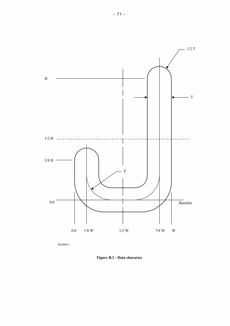
- 71 -
98-0056-A
1/2 H
3/8 H
0,0
0,0 1/8 W 1/2 W 7/8 W W
Baseline
T
1/2 T
H
Figure B.2 - Data character
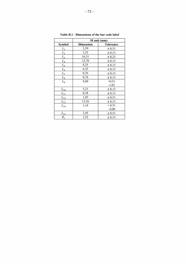
- 72 -
Table B.1 - Dimensions of the bar code label
SI unit (mm)Symbol Dimension Tolerance
L1 5,59 ± 0,51L2 3,25 ± 0,13L3 16,51 ± 0,25L4 12,70 ± 0,13L5 8,25 ± 0,13L6 6,35 ± 0,13L7 0,76 ± 0,13L8 0,76 ± 0,13L9 9,80 +0,51
-1,02L10 5,21 ± 0,13L11 0,38 ± 0,13L12 1,65 ± 0,51L13 13,26 ± 0,13L14 1,14 + 0,51
- 0,00L15 3,45 ± 0,51R1 1,52 ± 0,13
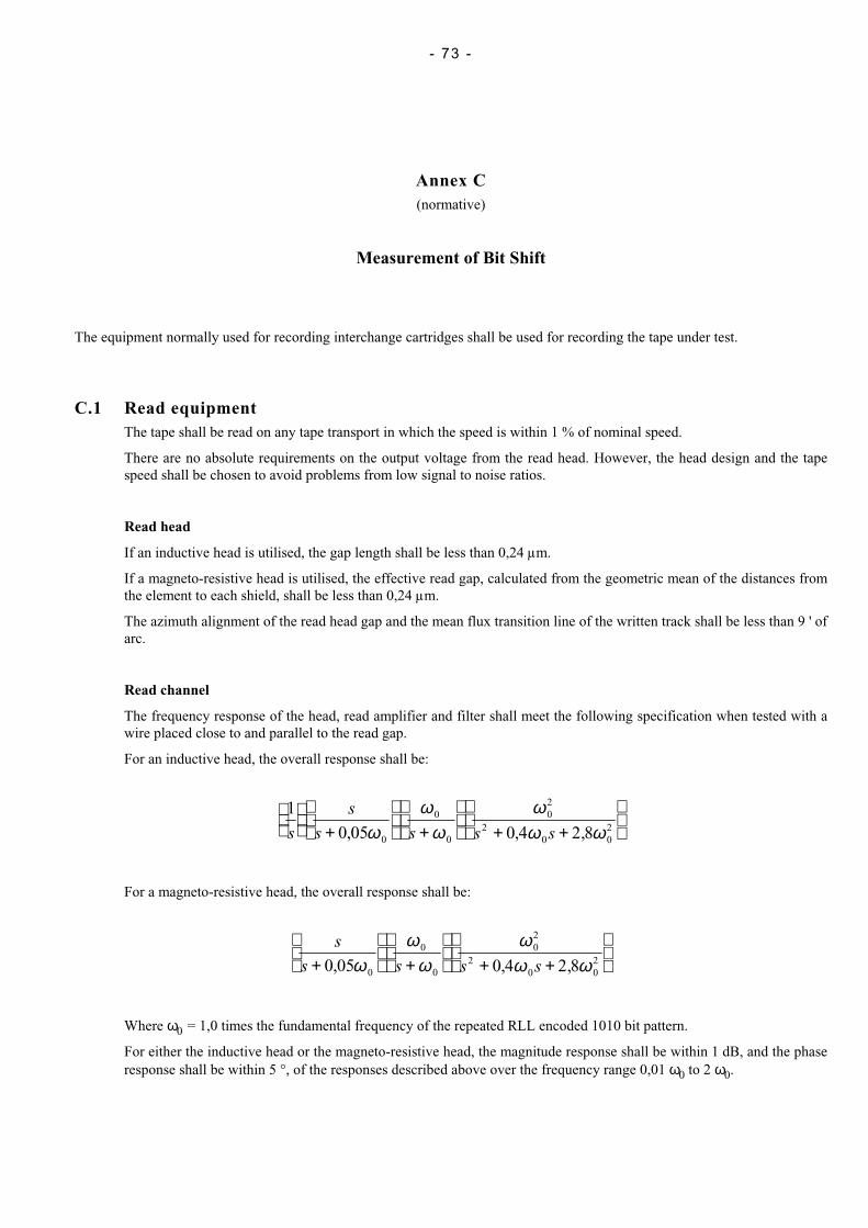
- 73 -
Annex C(normative)
Measurement of Bit Shift
The equipment normally used for recording interchange cartridges shall be used for recording the tape under test.
C.1 Read equipmentThe tape shall be read on any tape transport in which the speed is within 1 % of nominal speed.
There are no absolute requirements on the output voltage from the read head. However, the head design and the tapespeed shall be chosen to avoid problems from low signal to noise ratios.
Read head
If an inductive head is utilised, the gap length shall be less than 0,24 µm.
If a magneto-resistive head is utilised, the effective read gap, calculated from the geometric mean of the distances fromthe element to each shield, shall be less than 0,24 µm.
The azimuth alignment of the read head gap and the mean flux transition line of the written track shall be less than 9 ' ofarc.
Read channel
The frequency response of the head, read amplifier and filter shall meet the following specification when tested with awire placed close to and parallel to the read gap.
For an inductive head, the overall response shall be:
1
0 05 0 4 2 80
0
0
02
20 0
2s
s
s s s s
+
+
+ +
, , ,ωω
ωω
ω ω
For a magneto-resistive head, the overall response shall be:
s
s s s s+
+
+ +
0 05 0 4 2 80
0
0
02
20 0
2, , ,ωω
ωω
ω ω
Where ω0 = 1,0 times the fundamental frequency of the repeated RLL encoded 1010 bit pattern.
For either the inductive head or the magneto-resistive head, the magnitude response shall be within 1 dB, and the phaseresponse shall be within 5 °, of the responses described above over the frequency range 0,01 ω0 to 2 ω0.
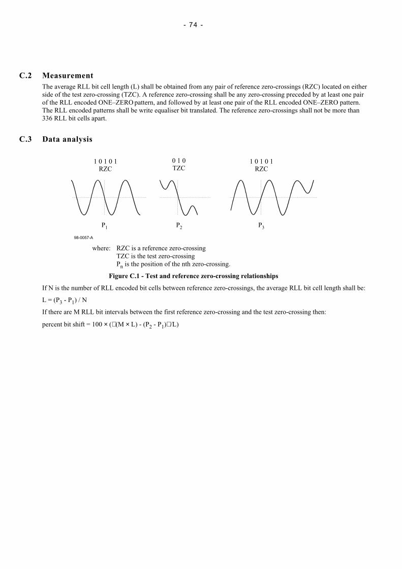
- 74 -
C.2 MeasurementThe average RLL bit cell length (L) shall be obtained from any pair of reference zero-crossings (RZC) located on eitherside of the test zero-crossing (TZC). A reference zero-crossing shall be any zero-crossing preceded by at least one pairof the RLL encoded ONE–ZERO pattern, and followed by at least one pair of the RLL encoded ONE–ZERO pattern.The RLL encoded patterns shall be write equaliser bit translated. The reference zero-crossings shall not be more than336 RLL bit cells apart.
C.3 Data analysis
98-0057-A
1 0 1 0 1RZC
0 1 0TZC
1 0 1 0 1RZC
P1 P2 P3
where: RZC is a reference zero-crossingTZC is the test zero-crossingPn is the position of the nth zero-crossing.
Figure C.1 - Test and reference zero-crossing relationships
If N is the number of RLL encoded bit cells between reference zero-crossings, the average RLL bit cell length shall be:
L = (P3 - P1) / N
If there are M RLL bit intervals between the first reference zero-crossing and the test zero-crossing then:
percent bit shift = 100 × ( (M × L) - (P2 - P1) /L)
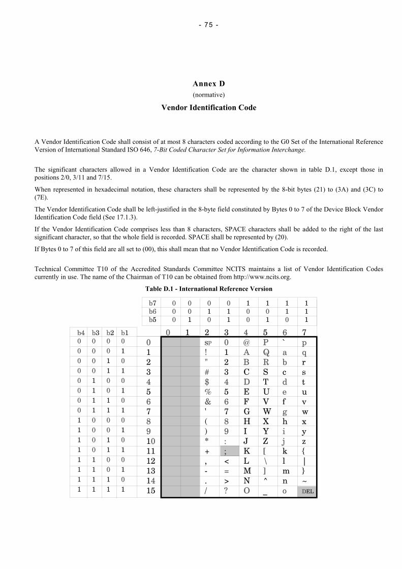
- 75 -
Annex D(normative)
Vendor Identification Code
A Vendor Identification Code shall consist of at most 8 characters coded according to the G0 Set of the International ReferenceVersion of International Standard ISO 646, 7-Bit Coded Character Set for Information Interchange.
The significant characters allowed in a Vendor Identification Code are the character shown in table D.1, except those inpositions 2/0, 3/11 and 7/15.
When represented in hexadecimal notation, these characters shall be represented by the 8-bit bytes (21) to (3A) and (3C) to(7E).
The Vendor Identification Code shall be left-justified in the 8-byte field constituted by Bytes 0 to 7 of the Device Block VendorIdentification Code field (See 17.1.3).
If the Vendor Identification Code comprises less than 8 characters, SPACE characters shall be added to the right of the lastsignificant character, so that the whole field is recorded. SPACE shall be represented by (20).
If Bytes 0 to 7 of this field are all set to (00), this shall mean that no Vendor Identification Code is recorded.
Technical Committee T10 of the Accredited Standards Committee NCITS maintains a list of Vendor Identification Codescurrently in use. The name of the Chairman of T10 can be obtained from http://www.ncits.org.
Table D.1 - International Reference Version

- 76 -
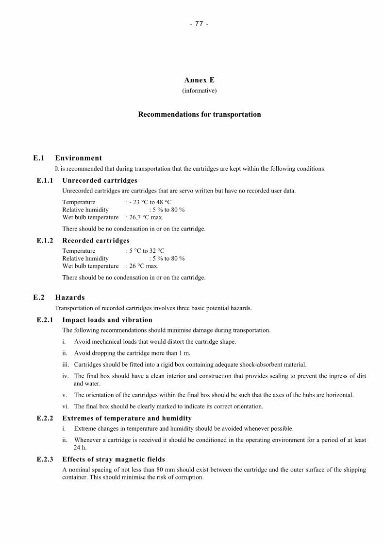
- 77 -
Annex E(informative)
Recommendations for transportation
E.1 EnvironmentIt is recommended that during transportation that the cartridges are kept within the following conditions:
E.1.1 Unrecorded cartridgesUnrecorded cartridges are cartridges that are servo written but have no recorded user data.
Temperature : - 23 °C to 48 °CRelative humidity : 5 % to 80 %Wet bulb temperature : 26,7 °C max.
There should be no condensation in or on the cartridge.
E.1.2 Recorded cartridgesTemperature : 5 °C to 32 °CRelative humidity : 5 % to 80 %Wet bulb temperature : 26 °C max.
There should be no condensation in or on the cartridge.
E.2 HazardsTransportation of recorded cartridges involves three basic potential hazards.
E.2.1 Impact loads and vibrationThe following recommendations should minimise damage during transportation.
i. Avoid mechanical loads that would distort the cartridge shape.
ii. Avoid dropping the cartridge more than 1 m.
iii. Cartridges should be fitted into a rigid box containing adequate shock-absorbent material.
iv. The final box should have a clean interior and construction that provides sealing to prevent the ingress of dirtand water.
v. The orientation of the cartridges within the final box should be such that the axes of the hubs are horizontal.
vi. The final box should be clearly marked to indicate its correct orientation.
E.2.2 Extremes of temperature and humidityi. Extreme changes in temperature and humidity should be avoided whenever possible.
ii. Whenever a cartridge is received it should be conditioned in the operating environment for a period of at least24 h.
E.2.3 Effects of stray magnetic fieldsA nominal spacing of not less than 80 mm should exist between the cartridge and the outer surface of the shippingcontainer. This should minimise the risk of corruption.

- 78 -

- 79 -
Annex F(informative)
Inhibitor tape
Any tape that reduces the performance of the tape drive or other tapes is called an inhibitor tape. Certain tape characteristics cancontribute to poor tape drive performance. These characteristics include: high abrasivity, high static friction to tape pathcomponents, poor edge conditions, excessive tape wear debris, electro-static charge build-up on the tape or tape pathcomponents, interlayer slippage, transfer of coating to the back of the next tape layer, separation of tape constituents causingdeposits that may lead to tape sticking or poor performance of other tapes. Tapes that have these characteristics may not givesatisfactory performance and can result in excessive errors.
Tapes to be used in this cartridge should not be inhibitor tapes.

- 80 -

- 81 -
Annex G(informative)
Tape durability
Testing and measurements performed on the cartridge using appropriate models of tape drives are described in G.1 and G.2.
G.1 Short-length durability and reliability testShort-length durability is the capability of the tape to withstand the wearing action encountered during repeatedaccesses to a short file of data. A permanent read error is one that persists for ten consecutive read passes.
G.1.1 RecommendationThere should be no permanent read errors for a minimum of 40 000 read-forward passes.
G.1.2 ProcedureEnsure the tape drive is clean before starting this test. As a test sample, use a minimum of four cartridges, written inan area free of read errors. The test area should consist of fifteen 262 144-byte records.
Each test cycle consists of a start operation at the beginning of the test area accessing all records sequentially in thetest area, and, using the backspace file, returning to the beginning of the test area. Ten attempts to read forwardshould be made for each read error before a permanent read error is logged.
Tape-path cleaning between passes is not permitted for this test.
The test should be performed in a normal operating environment for the tape and the tape drive.
G.2 Long-length durability and reliability testLong-length durability is the capability of the tape to resist the wearing action encountered while cycling full length ona tape drive.
G.2.1 RecommendationAfter 200 full file read-while-write passes the temporary write errors should not increase by more than eight in anycartridge tested, and there should not be any permanent read or write errors. A full file pass consists of four completewraps, where a wrap is one complete cycle from beginning of tape to end of tape and a return to the beginning oftape.
G.2.2 ProcedureClean the tape drive before starting this test. The data should be successfully written in both a streaming and start-stop mode. Start-stop should be 20 to 200 cycles per half-wrap (full length of tape). Tape-path cleaning betweenpasses is not permitted for this test. The test should be performed in a normal operating environment for the tape andtape unit.

- 82 -

Free printed copies can be ordered from:
ECMA114 Rue du RhôneCH-1204 GenevaSwitzerland
Fax: +41 22 849.60.01Email: [email protected]
Files of this Standard can be freely downloaded from the ECMA web site (www.ecma.ch). This site gives full information onECMA, ECMA activities, ECMA Standards and Technical Reports.

ECMA
114 Rue du RhôneCH-1204 GenevaSwitzerland
See inside cover page for obtaining further soft or hard copies.