Embed Size (px)
Citation preview

Software System Development forSpacecraft Data Handling & Control
Data Handling System Conceptsand Structure
Document No.: TERMA/OBOSS-2/TN/013
Date: 13.09.99
Issue: 1
Revision: -
Distribution: TERMA
Prepared by: Gert Caspersen
Authorised by: Carsten Jørgensen
The intellectual property of this document is vested in TERMA Elektronik AS.

Software System Development for SC Data Handling & ControlData Handling System Concepts and Structure
TERMA/OBOSS-2/TN/013 i
Document Change Record
Issue Date Change
1 13.09.99 Initial Issue
Software System Development for SC Data Handling & ControlData Handling System Concepts and Structure
TERMA/OBOSS-2/TN/013ii
Table of Contents
1 Introduction . . . . . . . . . . . . . . . . . . . . . . . . . . . . . . . . . . . . . . . . . . . . . . . . . . . . . . 1
1.1 Scope . . . . . . . . . . . . . . . . . . . . . . . . . . . . . . . . . . . . . . . . . . . . . . . . . . . . . . . 1
1.2 Abbreviations and Acronyms . . . . . . . . . . . . . . . . . . . . . . . . . . . . . . . . . . . . 1
1.3 Document Outline . . . . . . . . . . . . . . . . . . . . . . . . . . . . . . . . . . . . . . . . . . . . . 1
2 Bibliography . . . . . . . . . . . . . . . . . . . . . . . . . . . . . . . . . . . . . . . . . . . . . . . . . . . . . . 3
3 Software System Development for Spacecraft Data Handling & Control . . . . . . . 4
3.1 Packet Utilisation Standard . . . . . . . . . . . . . . . . . . . . . . . . . . . . . . . . . . . . . . 4
3.2 Data Handling System Platform . . . . . . . . . . . . . . . . . . . . . . . . . . . . . . . . . . 4
4 Interpretation of Packet Utilisation Standard . . . . . . . . . . . . . . . . . . . . . . . . . . . . . 6
4.1 Executive Summary of PUS . . . . . . . . . . . . . . . . . . . . . . . . . . . . . . . . . . . . . 6
4.1.1 Telecommand Verification Service . . . . . . . . . . . . . . . . . . . . . . . . . . 6
4.1.2 Device Level Commanding Service . . . . . . . . . . . . . . . . . . . . . . . . . 6
4.1.3 Housekeeping & Diagnostic Data Reporting Service . . . . . . . . . . . . 6
4.1.4 Event Reporting Service . . . . . . . . . . . . . . . . . . . . . . . . . . . . . . . . . . 7
4.1.5 Function Management Service . . . . . . . . . . . . . . . . . . . . . . . . . . . . . 8
4.1.6 Onboard Scheduling Service . . . . . . . . . . . . . . . . . . . . . . . . . . . . . . . 8
4.1.7 Onboard Monitoring Service . . . . . . . . . . . . . . . . . . . . . . . . . . . . . . . 9
4.1.8 Onboard Storage and Retrieval Service . . . . . . . . . . . . . . . . . . . . . . 10
4.2 Supported Services . . . . . . . . . . . . . . . . . . . . . . . . . . . . . . . . . . . . . . . . . . . 10
4.3 Telecommand Verification . . . . . . . . . . . . . . . . . . . . . . . . . . . . . . . . . . . . . 11
4.4 Device Level Commanding . . . . . . . . . . . . . . . . . . . . . . . . . . . . . . . . . . . . 12
Software System Development for SC Data Handling & ControlData Handling System Concepts and Structure
TERMA/OBOSS-2/TN/013 iii
4.5 Housekeeping & Diagnostic Reporting . . . . . . . . . . . . . . . . . . . . . . . . . . . . 13
4.6 Event Reporting . . . . . . . . . . . . . . . . . . . . . . . . . . . . . . . . . . . . . . . . . . . . . 13
4.7 Memory Management . . . . . . . . . . . . . . . . . . . . . . . . . . . . . . . . . . . . . . . . . 14
4.8 Function Management . . . . . . . . . . . . . . . . . . . . . . . . . . . . . . . . . . . . . . . . . 14
4.9 Onboard Scheduling . . . . . . . . . . . . . . . . . . . . . . . . . . . . . . . . . . . . . . . . . . 15
4.10 Onboard Monitoring . . . . . . . . . . . . . . . . . . . . . . . . . . . . . . . . . . . . . . . . . . 15
4.11 Onboard Storage & Retrieval . . . . . . . . . . . . . . . . . . . . . . . . . . . . . . . . . . . 16
4.12 Onboard Traffic Management . . . . . . . . . . . . . . . . . . . . . . . . . . . . . . . . . . . 17
5 Understanding the OBOSS-II Software . . . . . . . . . . . . . . . . . . . . . . . . . . . . . . . . 18
5.1 General Architecture . . . . . . . . . . . . . . . . . . . . . . . . . . . . . . . . . . . . . . . . . . 18
5.2 Reusability of Architecture . . . . . . . . . . . . . . . . . . . . . . . . . . . . . . . . . . . . . 19
5.3 Rationale . . . . . . . . . . . . . . . . . . . . . . . . . . . . . . . . . . . . . . . . . . . . . . . . . . . 19
5.4 Telecommand and Telemetry Flows . . . . . . . . . . . . . . . . . . . . . . . . . . . . . . 20
5.5 Data Flow . . . . . . . . . . . . . . . . . . . . . . . . . . . . . . . . . . . . . . . . . . . . . . . . . . 22
5.6 Control Flow . . . . . . . . . . . . . . . . . . . . . . . . . . . . . . . . . . . . . . . . . . . . . . . . 23
5.7 Structuring of Software Components . . . . . . . . . . . . . . . . . . . . . . . . . . . . . 24
5.7.1 Basic Services . . . . . . . . . . . . . . . . . . . . . . . . . . . . . . . . . . . . . . . . . 25
5.7.2 CDH Structure . . . . . . . . . . . . . . . . . . . . . . . . . . . . . . . . . . . . . . . . . 26
5.7.3 PUS Services . . . . . . . . . . . . . . . . . . . . . . . . . . . . . . . . . . . . . . . . . . 26
5.7.4 PROBA . . . . . . . . . . . . . . . . . . . . . . . . . . . . . . . . . . . . . . . . . . . . . . 27
Appendix A
General Control Flows . . . . . . . . . . . . . . . . . . . . . . . . . . . . . . . . . . . . . . . . . . . . . 28
A.1 Hard Real-Time Control Flows . . . . . . . . . . . . . . . . . . . . . . . . . . . . . . . . . . 30
A.2 Sporadic Task . . . . . . . . . . . . . . . . . . . . . . . . . . . . . . . . . . . . . . . . . . . . . . . 31
A.3 Cyclic Task . . . . . . . . . . . . . . . . . . . . . . . . . . . . . . . . . . . . . . . . . . . . . . . . . 32
A.4 Protected Object . . . . . . . . . . . . . . . . . . . . . . . . . . . . . . . . . . . . . . . . . . . . . 33
Software System Development for SC Data Handling & ControlData Handling System Concepts and Structure
TERMA/OBOSS-2/TN/013iv
Software System Development for SC Data Handling & ControlData Handling System Concepts and Structure
TERMA/OBOSS-2/TN/013 1
1 Introduction
1.1 ScopeThe current document is to describe the Concepts and overall structure of the softwareframework and components resulting from the ‘Software system Development forSpacecraft Data Handling & Control’ project.
The software components were originaly developed for an 1750A platform as part ofthe ESTEC project ‘Onboard Operations Support Software’. As part of the ‘Softwaresystem Development for Spacecraft Data Handling & Control’ project they have beenported to an ERC32 platform.
1.2 Abbreviations and Acronyms
OBOSS-II Software System Development for Spacecraft Data Handling& Control
PUS Packet Utilisation Standard
IF Interface
1.3 Document OutlineA general introduction to the ‘Software System Development for Spacecraft DataHandling and Control’ project is given in chapter 3.
The Packet Utilisation Standard is a fundamental baseline for the work carried out inthe project. Chapter 4 provides an executive summary of the standard and elaborateson any deviations or interpretations that has been applied in the implementation of theservices from the standard.
Chapter 5 introduces the architecture of the reusable software developed in theOBOSS-II project. An outline of the general data flows and control flows in thesystem is given in order to ease the reuse process.
Software System Development for SC Data Handling & ControlData Handling System Concepts and Structure
TERMA/OBOSS-2/TN/0132
Appendix A introduces the set of control structures that has been applied in thereusable software components.
Software System Development for SC Data Handling & ControlData Handling System Concepts and Structure
TERMA/OBOSS-2/TN/013 3
2 Bibliography
[PTC] Packet Telecommand StandardEuropean Space AgencyPSS-04-107
[PTM] Packet Telemetry StandardEuropean Space AgencyPSS-04-106
[PUS] Packet Utilisation StandardESA, PSS-07-101Issue 1, 1994
Software System Development for SC Data Handling & ControlData Handling System Concepts and Structure
TERMA/OBOSS-2/TN/0134
3 Software System Developmentfor Spacecraft Data Handling &Control
The goal of the’Software System Development for Spacecraft Data Handling &Control’ (OBOSS-II) project was to develop a reusable onboard software architectureimplementing a subset of the services defined in Packet Utilisation Standard [PUS] ona command and data handling platform. This architecture shall be able to support andease (through intensive reuse) development of onboard command and data handlingsoftware for a series of future missions.
Consequently, the context of the OBOSS-II is dominated by three elements: the PacketUtilisation Standard (PUS), the satellite platforms on which the OBOSS-II architectureis to build, and the reusable software components being part of the reusable architec-ture. Each of these is discussed in the following.
3.1 Packet Utilisation StandardThis standard defines several general services whose onboard implementationsupports satellite operation. It defines the application level of Packet TelecommandStandard [PTC] and Packet Telemetry Standard [PTM].
It is not in the scope of the OBOSS-II project to develop a complete PUS implementa-tion. Consequently, a subset of the services and subservices have been selected forimplementation.
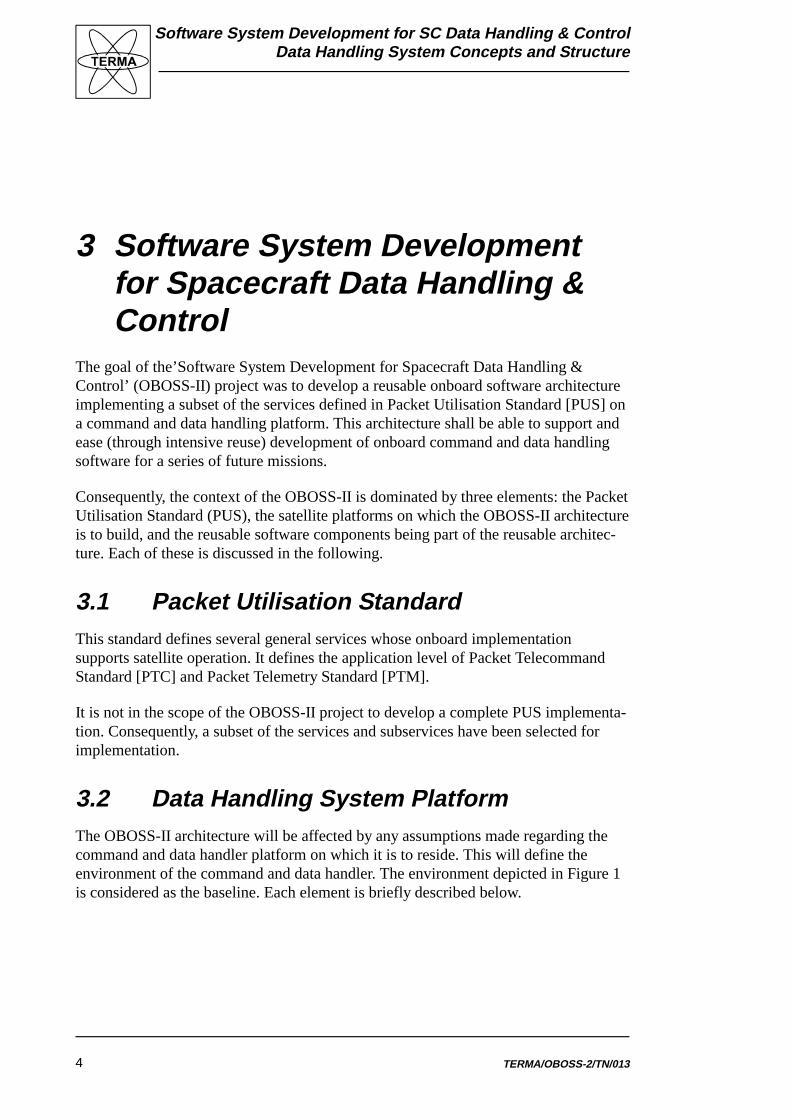
3.2 Data Handling System PlatformThe OBOSS-II architecture will be affected by any assumptions made regarding thecommand and data handler platform on which it is to reside. This will define theenvironment of the command and data handler. The environment depicted in Figure 1is considered as the baseline. Each element is briefly described below.
Software System Development for SC Data Handling & ControlData Handling System Concepts and Structure
TERMA/OBOSS-2/TN/013 5
Subsystem 1I/F
Subsystem 2I/F
Subsystem NI/F
Data HandlingSystem
COMSubsystem
GroundSegment
Pay
loa
d B
us
U
p/D
ow
nlin
k B
us
Figure 1: Data Handling System Platform
Ground Segment
Control centre, ground stations etc. responsible for operation of the satellite on whichcommand and data handler platform resides.
COM Subsystem
Communication subsystem providing the onboard support for the radio link betweenspace segment and ground segment. It implements several layers in the ESA PacketTelecommand Standard [PTC] and Packet Telemetry Standard [PTM].
Up/Downlink Bus
Onboard bus dedicated to uplink and downlink data flows.
Data Handling System
Onboard subsystem responsible for commanding of onboard subsystems and datacollection from these.
Payload Bus
Any bus chosen for interfacing to payloads. May be multidrop bus – as shown – orserial busses in star shaped configuration.
Subsystem 1 I/F .. Subsystem N I/F
Collection of onboard subsystems controlled by the data handling system. Includespayloads as well as attitude control subsystem, electrical power subsystem etc.
Software System Development for SC Data Handling & ControlData Handling System Concepts and Structure
TERMA/OBOSS-2/TN/0136
4 Interpretation of Packet Utilisa-tion Standard
Although the packet utilisation standard aims at being unambiguous and complete,room is still left for interpretation. Any implementation may have to deviate due tolimitations imposed by the target platform. For each of the supported PUS services,this chapter describes any interpretations and limitations present in the OBOSS-IIimplementation.
4.1 Executive Summary of PUSThis section is to give a short informal introduction to the PUS services implementedin the OBOSS-II project.
4.1.1 Telecommand Verification ServiceAny of the telemetry packages from this service may be generated by PUS. We have touse these for acknowledgement of the correct execution of telecommands we send.
4.1.2 Device Level Commanding ServiceTwo subservices are supported:
1. On/Off Commands
2. Register Load Commands
Such commands have to be transformed into messages on the OBDH bus in somesimple way. These commands are important as they provide ground control with asimple way of bypassing the more advanced PUS functions.
4.1.3 Housekeeping & Diagnostic Data ReportingService
Housekeeping/diagnostic collection is based on a table of report definitions associatedwith each subsystem onboard. This table is initially empty. Report definitions indicatethat a report shall be generated with a given interval.
The report is identified by a unique report ID (being unique for the subsystem inquestion). The content of the report is based on a list of parameter numbers tellingwhat parameters are to be sampled in the report. These parameter numbers are unique
Software System Development for SC Data Handling & ControlData Handling System Concepts and Structure
TERMA/OBOSS-2/TN/013 7
over the entire onboard software, meaning that the list of possible parameters and theirassociated types have to be defined when OBOSS-II is tailored for a given mission.
Here we support the following PUS services:
Define Housekeeping/Diagnostic Data Report
These commands insert report definitions in the above table. The commands areaimed at the subsystem whose parameters are to be monitored. Report generation isenabled after definition has succeeded (see below). Any report in progress is dis-carded.
Clear Housekeeping/Diagnostic Data Report
One or more report definitions are removed from the above table. Consequently, theassociated housekeeping collection stops. Any report in progress is discarded.
En/Disable Housekeeping/Diagnostic Data Report
Starts and stops generation of housekeeping reports for the identified report definitionswithout removing these from the table.
Report Housekeeping/Diagnostic Report Definitions
Requests a definition report showing the current definitions for the identified reports.
Select Periodic/Filtered Report Generation Mode
Switches reporting between periodic mode and filtered mode. In filtered mode reportsare generated when one of the contained parameter values exceeds a given thresholdor a given time has elapsed.
Report Masked Parameters
Generates report identifying the parameters that are not thresholded in a FilteredReport Generation Mode.
4.1.4 Event Reporting ServiceThis service only includes telemetry. Such reports are used to signal severe errors inthe onboard system (including the software).

Software System Development for SC Data Handling & ControlData Handling System Concepts and Structure
TERMA/OBOSS-2/TN/0138
4.1.5 Function Management ServiceCommands associated to this service may be used for implementation of commandsnot otherwise covered by the PUS. The idea is to have one instance of this service foreach subsystem. A function and an activity are both sequences of simple actions (e.g.OBDH bus interrogations) directed at the associated subsystem. However, severalactivities may be associated with one function (see below).
Activate Function
Execute the sequence of actions associated with the identified function based on theprovided parameters values. Often used to enable a mode for a subsystem.
Deactivate Function
Perform a sequence of actions. Often used to disable a mode for the associatedsubsystem.
Perform Activity
Perform an activity of the identified function (if this is enabled).
4.1.6 Onboard Scheduling ServiceImplements a command schedule being a collection of time tagged PUS tele-commands divided into subschedules. The time tags may be absolute or relative toevents such as the enabling of a subschedule.
Commands in the schedule are to be released when their time is due (based on onecentral onboard clock).
En/Disable Release of Telecommands or Subschedules
Enabling or disabling of a subschedule enables or disables all commands in thissubschedule. Disabled commands are not released for execution even when their timeis due. Enabled commands are released when they are due.
Reset Command Schedule
Remove all commands and subschedules from the schedule.
Insert Telecommands
Inserts telecommands in the command schedule and a specific subschedule.
Delete Telecommands
Delete telecommands explicitly identified in command or having a time tag within agiven time interval.
Software System Development for SC Data Handling & ControlData Handling System Concepts and Structure
TERMA/OBOSS-2/TN/013 9
Report Schedule Contents
Dumps specified part of the current contents of Command Schedule in a report.
4.1.7 Onboard Monitoring ServiceMaintains a table of expected parameter values or limits for an associated subsystem.Parameter values are sampled from the subsystem at specified intervals. A report is tobe generated when one of these values is not within the nominal range. The tabledefines a collection of parameters (through their unique parameter number, seehousekeeping above) that are to be monitored. Each of these parameters has associateda set of check definitions being checked with a given interval. An out-of-limit eventoccurs if a parameter value has been outside the nominal interval a specified numberof times. Out of limit events are collected in reports being sent down at some point intime.
Onboard procedures may be associated to the occurrence of out-of-limit eventsallowing for autonomous anomaly handling onboard.
En/Disable Monitoring
Controls whether or not specified parameters are to be monitored. Their correspondingnominal definitions remain in the table.
Clear Monitoring List
Remove all check definitions from the table. Consequently stops all monitoring.
Add Parameters
Add check definitions to table. Associates check definitions to parameters, startingmonitoring of these.
Delete Parameters
Remove specified parameters from table meaning that monitoring of these stops.
Modify Parameter Checking Definition
Modifies check definitions associated to parameters.
Report Monitoring List
Generates report telemetry showing current contents of table.
Report Current Out-Of-Limit List
Generates report showing out-of-limit events currently valid (meaning that theparameter value has not returned to nominal values).
Software System Development for SC Data Handling & ControlData Handling System Concepts and Structure
TERMA/OBOSS-2/TN/01310
4.1.8 Onboard Storage and Retrieval ServiceSimilar to old tape recorders. Telemetry of given types is stored (in FIFO order) forlater downlink on request. Several stores may exist onboard. They may or may not beshared among subsystems. Definition of what telemetry is to be stored where (or notstored at all) may be controlled through telecommands.
Storage of telemetry is controlled through storage selections. These identify wheretelemetry of a given type/subtype is to be stored (or whether they are not to be storedat all). If some type of telemetry does not have an associated storage selection, then thetelemetry is downlinked immediately.
En/Disable Storage
Starts and stops storage of telemetry in identified packet stores. Telemetry whosestorage is disabled is downlinked immediately.
Add/Remove Types/Subtypes to Storage Selection
Defines that telemetry of given types/subtypes are to be stored in identified store byadding these to the collection of storage selections.
Report Storage Selection Definition
Requests report of storage selections for identified packet stores.
Downlink Packet Store Contents for Packet Range / Time Period
Results in specified telemetry packets being submitted for downlink. Specificationbased on sequence count interval or time span. Note that these time stamps are basedon reception time in the store and not the time stamp in the telemetry header.
Delete Contents of Packet Store up to Specified Packet / Storage Time
Remove telemetry packets matching the given criteria, meaning that they have asequence number or time stamp less than the specified one. May also be used to deletethe entire contents of all stores or a given store, or all packets of a given type.
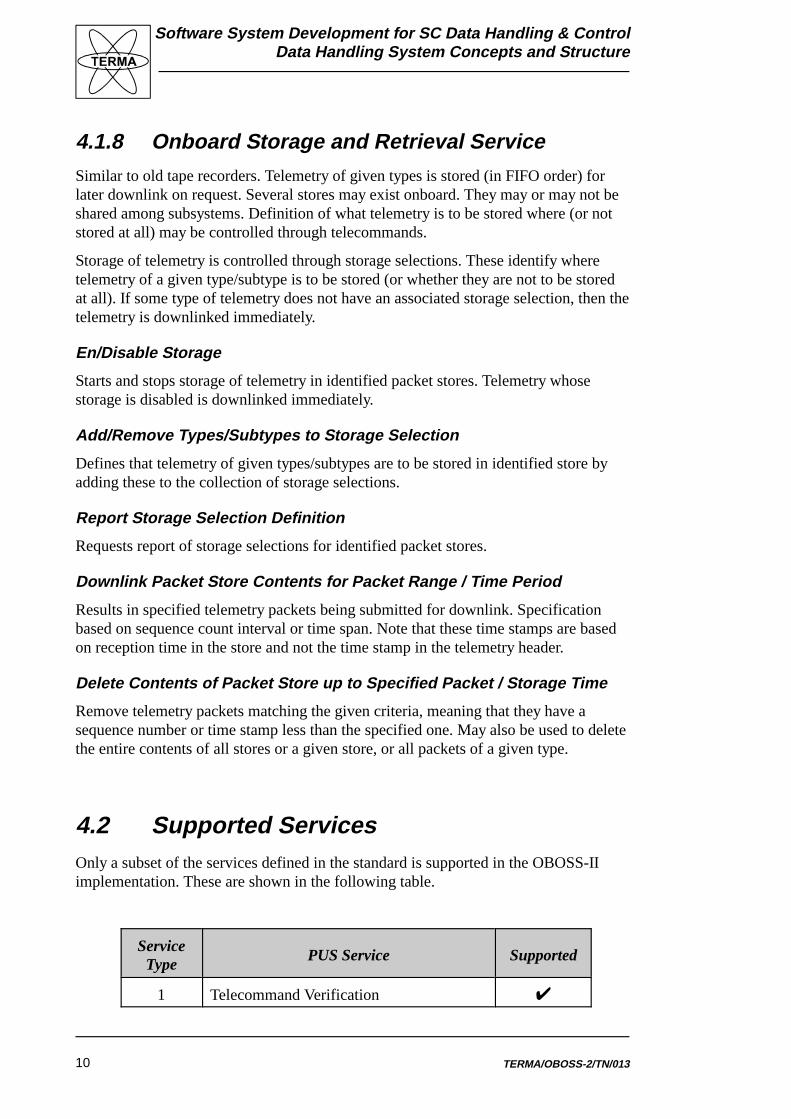
4.2 Supported ServicesOnly a subset of the services defined in the standard is supported in the OBOSS-IIimplementation. These are shown in the following table.
ServiceType
PUS Service Supported
1 Telecommand Verification U
Software System Development for SC Data Handling & ControlData Handling System Concepts and Structure
ServiceType
PUS Service Supported
TERMA/OBOSS-2/TN/013 11
2 Device Level Commanding U
3 Housekeeping & Diagnostic Reporting U
4 Parameter Statistics Reporting
5 Event Reporting U
6 Memory Management U
7 Task Management
8 Function Management U
9 Time Management
10 Time Reporting
11 Onboard Scheduling U
12 Onboard Monitoring U
13 Large Data Transfer
14 Packet Transmission Control
15 Onboard Storage & Retrieval U
16 Onboard Traffic Management U
17 Test
In the following sections, each of the supported services will be dealt with.
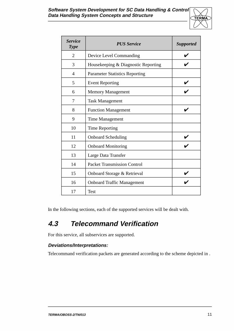
4.3 Telecommand VerificationFor this service, all subservices are supported.
Deviations/Interpretations:
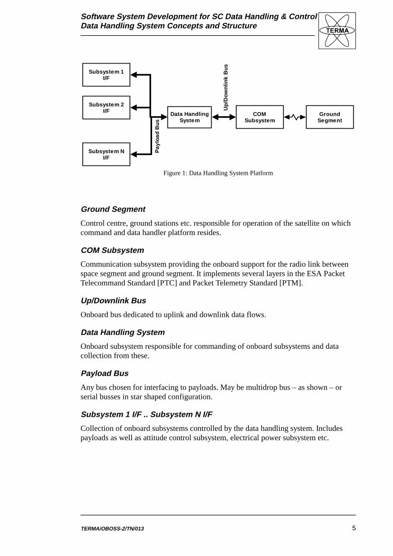
Telecommand verification packets are generated according to the scheme depicted in .
Software System Development for SC Data Handling & ControlData Handling System Concepts and Structure
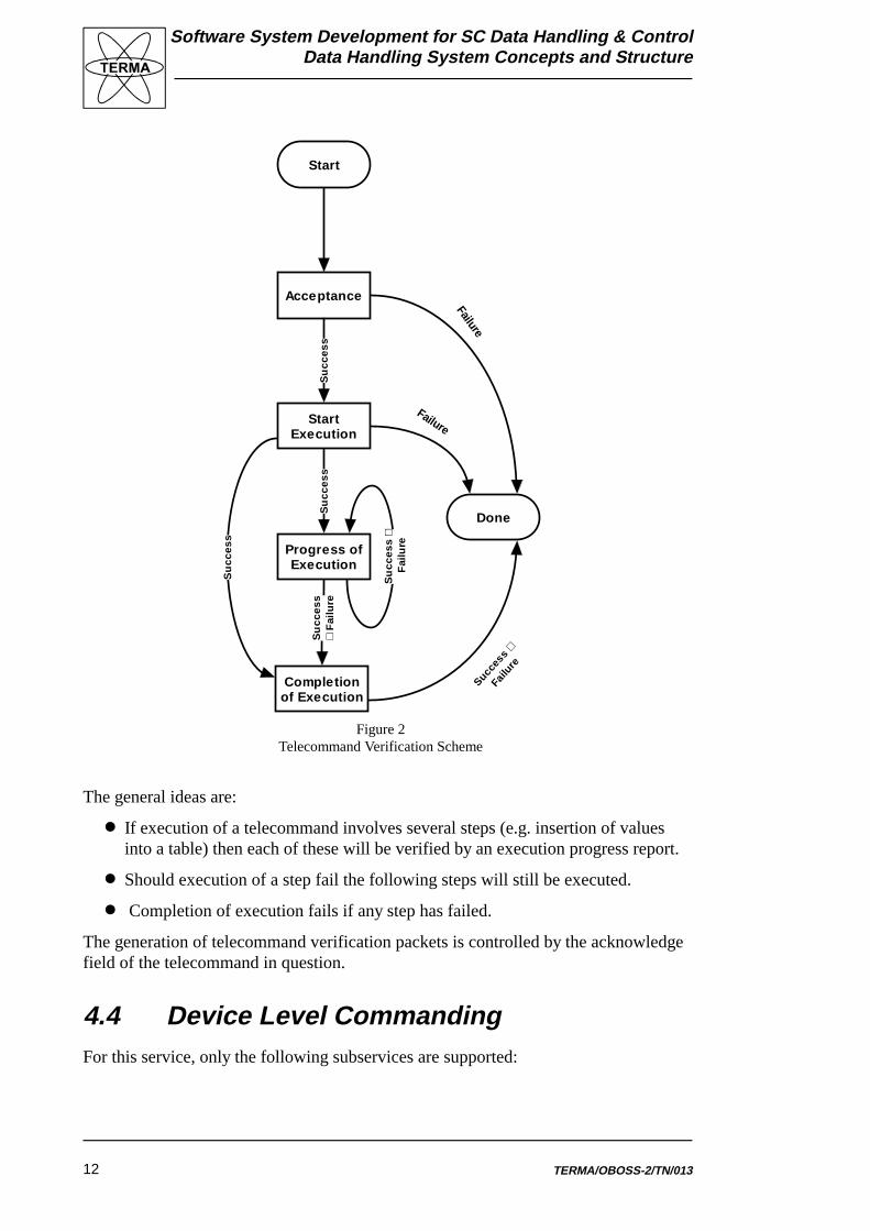
TERMA/OBOSS-2/TN/01312
Acceptance
StartExecution
Progress ofExecution
Completionof Execution
Su
cces
s
Fai
lure
Su
cces
s
Fai
lure
Su
cces
sS
ucc
ess
Done
Start
Su
cces
s
Succes
s
Fai
lure
Failure
Failure
Figure 2Telecommand Verification Scheme
The general ideas are:
� If execution of a telecommand involves several steps (e.g. insertion of valuesinto a table) then each of these will be verified by an execution progress report.
� Should execution of a step fail the following steps will still be executed.
� Completion of execution fails if any step has failed.
The generation of telecommand verification packets is controlled by the acknowledgefield of the telecommand in question.
4.4 Device Level CommandingFor this service, only the following subservices are supported:
Software System Development for SC Data Handling & ControlData Handling System Concepts and Structure
TERMA/OBOSS-2/TN/013 13
PUS Subservice Subtype
On/Off 1
Register Load 2
Deviations/Interpretations:
� Register data included in register load commands must be unsigned integers.
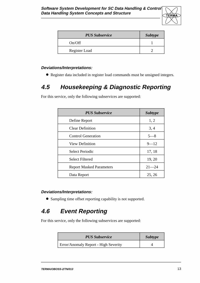
4.5 Housekeeping & Diagnostic ReportingFor this service, only the following subservices are supported:
PUS Subservice Subtype
Define Report 1, 2
Clear Definition 3, 4
Control Generation 5—8
View Definition 9—12
Select Periodic 17, 18
Select Filtered 19, 20
Report Masked Parameters 21—24
Data Report 25, 26
Deviations/Interpretations:
� Sampling time offset reporting capability is not supported.
4.6 Event ReportingFor this service, only the following subservices are supported:
PUS Subservice Subtype
Error/Anomaly Report - High Severity 4
Software System Development for SC Data Handling & ControlData Handling System Concepts and Structure
TERMA/OBOSS-2/TN/01314
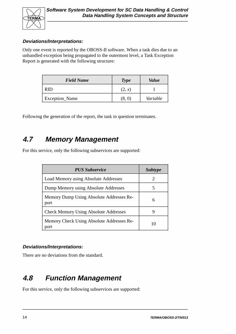
Deviations/Interpretations:
Only one event is reported by the OBOSS-II software. When a task dies due to anunhandled exception being propagated to the outermost level, a Task ExceptionReport is generated with the following structure:
Field Name Type Value
RID (2, x) 1
Exception_Name (8, 0) Variable
Following the generation of the report, the task in question terminates.
4.7 Memory ManagementFor this service, only the following subservices are supported:
PUS Subservice Subtype
Load Memory using Absolute Addresses 2
Dump Memory using Absolute Addresses 5
Memory Dump Using Absolute Addresses Re-port
6
Check Memory Using Absolute Addresses 9
Memory Check Using Absolute Addresses Re-port
10
Deviations/Interpretations:
There are no deviations from the standard.
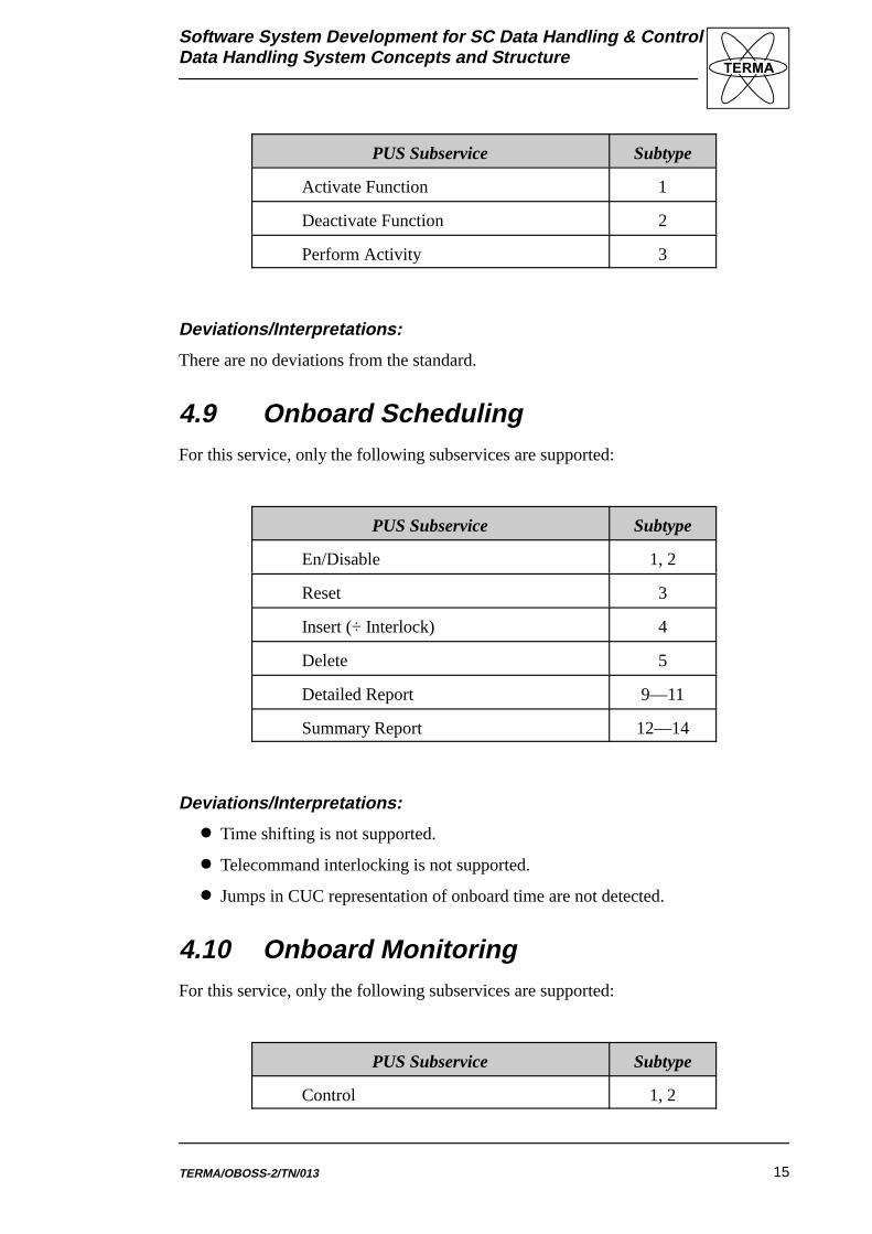
4.8 Function ManagementFor this service, only the following subservices are supported:
Software System Development for SC Data Handling & ControlData Handling System Concepts and Structure
TERMA/OBOSS-2/TN/013 15
PUS Subservice Subtype
Activate Function 1
Deactivate Function 2
Perform Activity 3
Deviations/Interpretations:
There are no deviations from the standard.
4.9 Onboard SchedulingFor this service, only the following subservices are supported:
PUS Subservice Subtype
En/Disable 1, 2
Reset 3
Insert (÷ Interlock) 4
Delete 5
Detailed Report 9—11
Summary Report 12—14
Deviations/Interpretations:
� Time shifting is not supported.
� Telecommand interlocking is not supported.
� Jumps in CUC representation of onboard time are not detected.
4.10 Onboard MonitoringFor this service, only the following subservices are supported:
PUS Subservice Subtype
Control 1, 2
Software System Development for SC Data Handling & ControlData Handling System Concepts and Structure
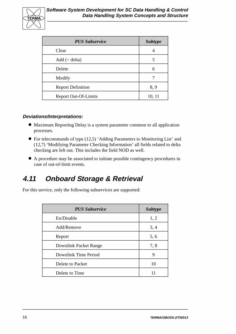
PUS Subservice Subtype
TERMA/OBOSS-2/TN/01316
Clear 4
Add (÷ delta) 5
Delete 6
Modify 7
Report Definition 8, 9
Report Out-Of-Limits 10, 11
Deviations/Interpretations:
� Maximum Reporting Delay is a system parameter common to all applicationprocesses.
� For telecommands of type (12,5) ‘Adding Parameters to Monitoring List’ and(12,7) ‘Modifying Parameter Checking Information’ all fields related to deltachecking are left out. This includes the field NOD as well.
� A procedure may be associated to initiate possible contingency procedures incase of out-of-limit events.
4.11 Onboard Storage & RetrievalFor this service, only the following subservices are supported:
PUS Subservice Subtype
En/Disable 1, 2
Add/Remove 3, 4
Report 5, 6
Downlink Packet Range 7, 8
Downlink Time Period 9
Delete to Packet 10
Delete to Time 11

Software System Development for SC Data Handling & ControlData Handling System Concepts and Structure
TERMA/OBOSS-2/TN/013 17
Deviations/Interpretations:
� If current storage selection definition is empty, and a storage selection definitionreport is requested then a verification failure is returned in response to thetelecommand. This allows ground to distinguish among all packet types beingselected and no packet types being selected.
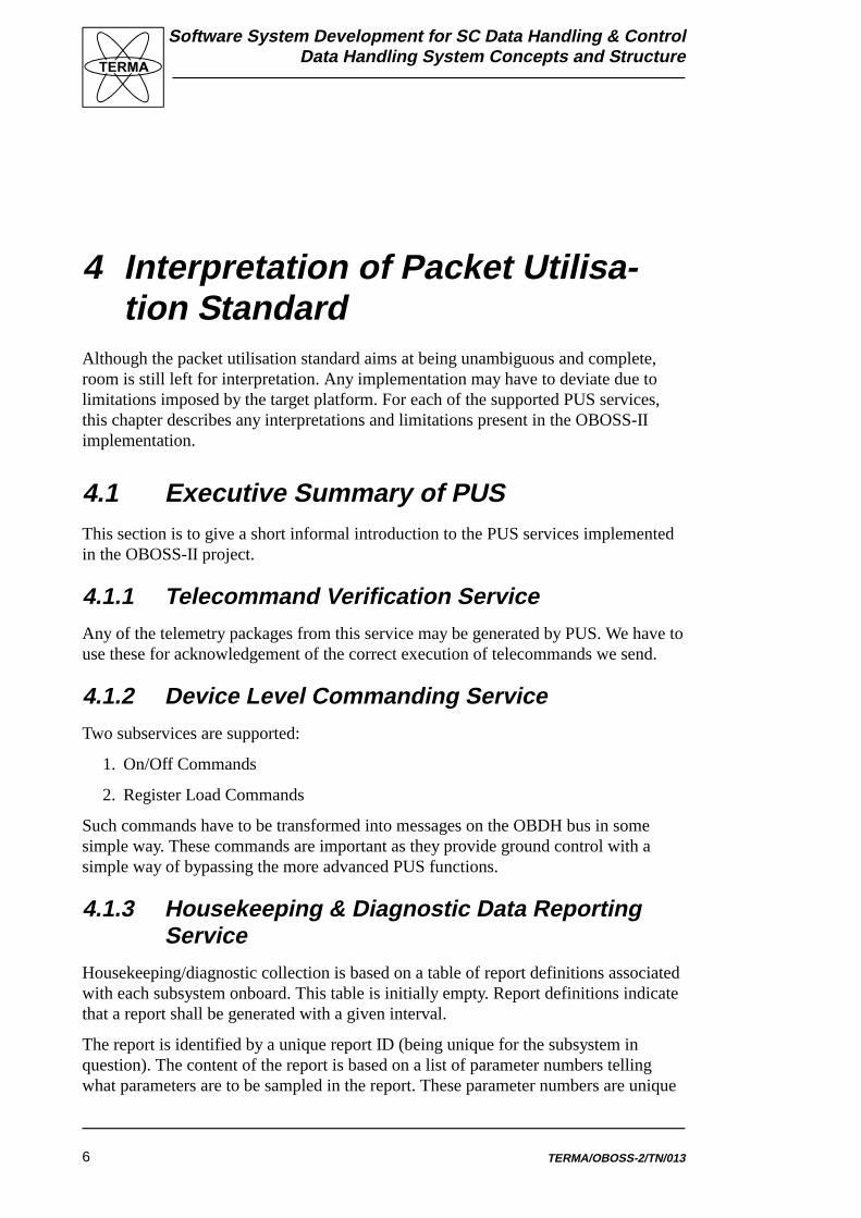
4.12 Onboard Traffic ManagementThis service is not defined in the current version of the packet utilisation standard.However, OBOSS-II has included a concept for onboard routing of telecommands andtelemetry allowing for a later adaptation to this service.
Software System Development for SC Data Handling & ControlData Handling System Concepts and Structure
TERMA/OBOSS-2/TN/01318
PacketRouter
GroundI/F
GroundSegment
PUSPackets
PacketTC/TM
Protocol
Subsystem X
Subsystem Y
ApplicationProcess 1
ApplicationProcess 2
ApplicationProcess 3
PUSPackets
PUSPackets
PUSPackets
Data Handling System
Figure 3: Command & Data Handler Architecture
5 Understanding the OBOSS-II Soft-ware
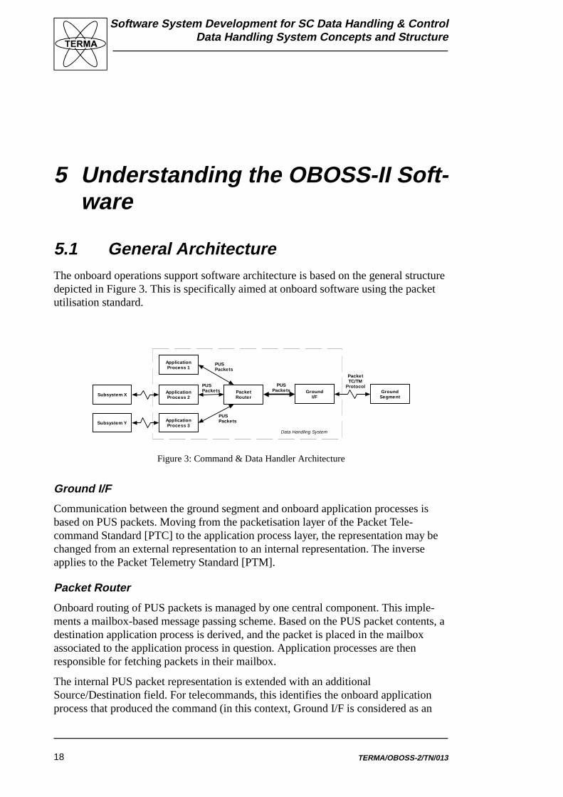
5.1 General ArchitectureThe onboard operations support software architecture is based on the general structuredepicted in Figure 3. This is specifically aimed at onboard software using the packetutilisation standard.
Ground I/F
Communication between the ground segment and onboard application processes isbased on PUS packets. Moving from the packetisation layer of the Packet Tele-command Standard [PTC] to the application process layer, the representation may bechanged from an external representation to an internal representation. The inverseapplies to the Packet Telemetry Standard [PTM].
Packet Router
Onboard routing of PUS packets is managed by one central component. This imple-ments a mailbox-based message passing scheme. Based on the PUS packet contents, adestination application process is derived, and the packet is placed in the mailboxassociated to the application process in question. Application processes are thenresponsible for fetching packets in their mailbox.
The internal PUS packet representation is extended with an additionalSource/Destination field. For telecommands, this identifies the onboard applicationprocess that produced the command (in this context, Ground I/F is considered as an
Software System Development for SC Data Handling & ControlData Handling System Concepts and Structure
TERMA/OBOSS-2/TN/013 19
application process). For telemetry, it identifies the destination of the telemetry packet(e.g. Ground I/F or an onboard packet store).
Subsystem 1 I/F .. Subsystem N I/F
Each onboard subsystem has associated one PUS application process responsible forimplementation of PUS services for that specific subsystem. The process is imple-mented by an interface object responsible for control of that specific subsystem.
5.2 Reusability of ArchitectureThe particular features that make the above structure well-suited for reuse in othercontexts are:
� The use of PUS packets for sending information, i.e. telecommands and teleme-try, among parts of the system provide a standardised interface to adhere to.
� Having a packet router as the focal point of the architecture means that the otherparts are loosely coupled to each other, and therefore changes in one part of thesystem can be kept local and will typically at most effect the packet router.
� The packet router also allows for a simple and efficient control structure in thateach application process, e.g. a payload, waits to collect a packet from the packetrouter, performs some required actions, potentially sends packets to otherprocesses via the router, and finally waits for the next packet to process.
� The structure, besides being simple, also increases the robustness of the system,because if an application process, e.g. a payload, for some reason stops, the restof the system can keep on executing (if no response from stopped process isrequired in order to proceed). This is because the only effect of a processbecoming inactive is that a buffer with PUS packets for it, will flow over, butevery process sending to it will be allowed to proceed. If an overflow of such abuffer is detected, it can be used as an indication of problems with the corre-sponding application process: handling the incoming packets may be too slow orit may be completely stopped.
� Adding a new payload is simple because all one need is to create a new applica-tion process with the above described simple control structure and add a newbuffer to the packet router.
5.3 RationaleDesigning onboard software for reuse, the architecture shall possess a number ofproperties:
� Scalability : The resulting structure shall be easily extendible and reducible inorder not to prohibit accommodation of future needs.
Software System Development for SC Data Handling & ControlData Handling System Concepts and Structure
TERMA/OBOSS-2/TN/01320
� Low Coupling : Software components in the design shall have as few interde-pendencies as possible. Consequently, spacecraft modifications affectingsubsystems including those components will be more easily accommodated.
� Layering : The structure shall be layered based on abstractions moving from theplatform or payload specific to the mission independent. Accommodation to newplatforms or payloads will then be focussed at components at the same abstrac-tion level.
� Adaptability : Software components that are likely to need changes to fit in anew system shall be functionally isolated as much as possible. This will ease theadaption.
Considering the architecture with respect to each of these properties provides thefollowing rationale for the architecture:
Scalability
New application processes may easily be added as the packet router and a couple ofdescriptor modules are the only onboard components possessing knowledge of the setof onboard application processes. Adding an application process only involvesextension of the set of application ids used by the packet router. Based on this, a newmailbox is provided for the new application process. In addition, new applicationprocess descriptors are included. Similarly, application processes that are not neededon a particular mission can easily be removed together with their application identifierand its associated mailbox.
Low Coupling
Application processes do not communicate with one another directly. All communica-tion takes place through the packet router. Failure of one application process does notaffect other application processes resulting in a more robust system.
Layering
The architecture presented above is partitioned into layers. A four-layer structure hasbeen developed as described in section ‘Structuring of Software Components’.
Adaptability
Modifying one application process, for example a payload interface, will only have alimited impact on other application processes. This is a direct result of the lowcoupling stated above.
5.4 Telecommand and Telemetry FlowsPacket Utilisation Standard includes an abstract model in which the onboard segmentis viewed as a collection of application processes. However, any given implementation– including the one in OBOSS – will place some operational constraints on thebehaviour of the data handling software. One important aspect during system level
Software System Development for SC Data Handling & ControlData Handling System Concepts and Structure
1 Ground is being represented by a special application process with its ownapplication process ID.
TERMA/OBOSS-2/TN/013 21
&RPPXQLFDWLRQ�6XEV\VWHP
8SOLQN
,�)
'RZQOLQN
,�)3DFNHW�5RXWHU
$SSOLFDWLRQ
3URFHVV��
$SSOLFDWLRQ
3URFHVV��
$SSOLFDWLRQ
3URFHVV��
Bytes
Bytes
Telecommand
Telemetry
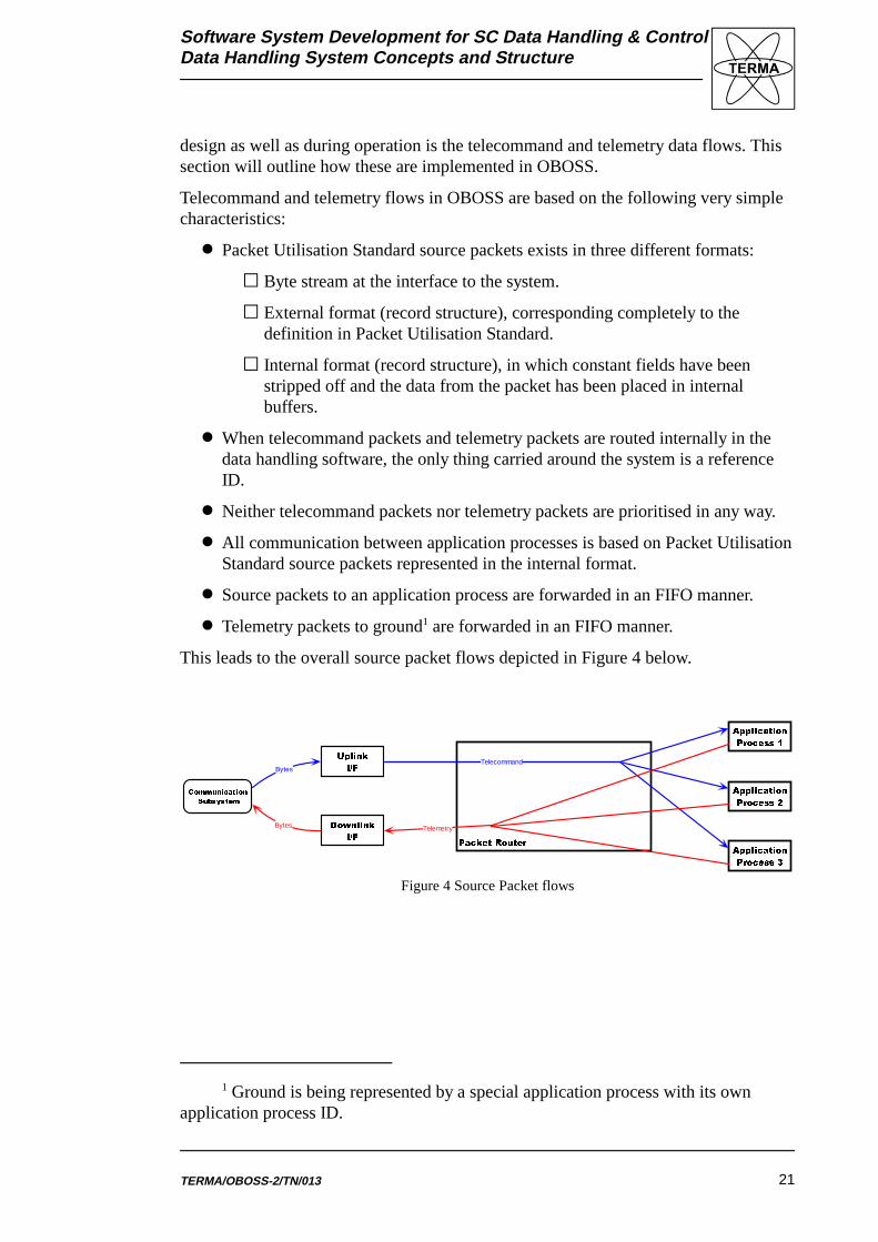
Figure 4 Source Packet flows
design as well as during operation is the telecommand and telemetry data flows. Thissection will outline how these are implemented in OBOSS.
Telecommand and telemetry flows in OBOSS are based on the following very simplecharacteristics:
� Packet Utilisation Standard source packets exists in three different formats:
* Byte stream at the interface to the system.
* External format (record structure), corresponding completely to thedefinition in Packet Utilisation Standard.
* Internal format (record structure), in which constant fields have beenstripped off and the data from the packet has been placed in internalbuffers.
� When telecommand packets and telemetry packets are routed internally in thedata handling software, the only thing carried around the system is a referenceID.
� Neither telecommand packets nor telemetry packets are prioritised in any way.
� All communication between application processes is based on Packet UtilisationStandard source packets represented in the internal format.
� Source packets to an application process are forwarded in an FIFO manner.
� Telemetry packets to ground1 are forwarded in an FIFO manner.
This leads to the overall source packet flows depicted in Figure 4 below.
Software System Development for SC Data Handling & ControlData Handling System Concepts and Structure
TERMA/OBOSS-2/TN/01322
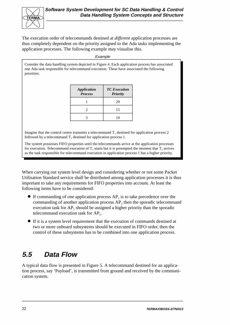
The execution order of telecommands destined at different application processes arethus completely dependent on the priority assigned to the Ada tasks implementing theapplication processes. The following example may visualise this.
When carrying out system level design and considering whether or not some PacketUtilisation Standard service shall be distributed among application processes it is thusimportant to take any requirements for FIFO properties into account. At least thefollowing items have to be considered:
� If commanding of one application process AP1 is to take precedence over thecommanding of another application process AP2 then the sporadic telecommandexecution task for AP1 should be assigned a higher priority than the sporadictelecommand execution task for AP2.
� If it is a system level requirement that the execution of commands destined attwo or more onboard subsystems should be executed in FIFO order, then thecontrol of these subsystems has to be combined into one application process.
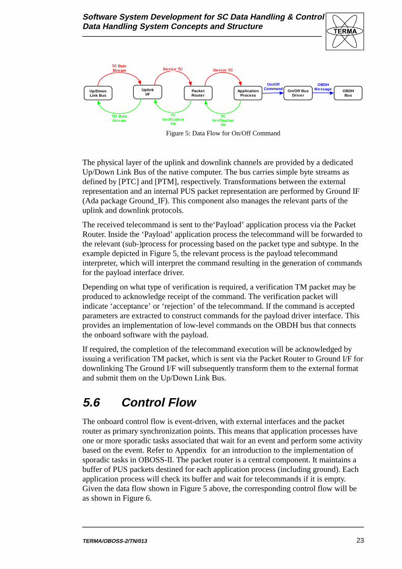
5.5 Data FlowA typical data flow is presented in Figure 5. A telecommand destined for an applica-tion process, say ‘Payload’, is transmitted from ground and received by the communi-cation system.
Consider the data handling system depicted in Figure 4. Each application process has associatedone Ada task responsible for telecommand execution. These have associated the followingpriorities:
ApplicationProcess
TC ExecutionPriority
1 20
2 15
3 10
Imagine that the control centre transmits a telecommand T1 destined for application process 2followed by a telecommand T2 destined for application process 1.
The system possesses FIFO properties until the telecommands arrive at the application processesfor execution. Telecommand execution of T1 starts but it is preempted the moment that T2 arrivesas the task responsible for telecommand execution in application process 1 has a higher priority.
Example
Software System Development for SC Data Handling & ControlData Handling System Concepts and Structure
TERMA/OBOSS-2/TN/013 23
Up/DownLink Bus
UplinkI/F
PacketRouter
ApplicationProcess
On/Off BusDriver
OBDHBus
On/OffCommand
OBDHMessage
TM ByteStream
TCVerification
TM
TC ByteStream Device TC Device TC
TCVerification
TM
Figure 5: Data Flow for On/Off Command
The physical layer of the uplink and downlink channels are provided by a dedicatedUp/Down Link Bus of the native computer. The bus carries simple byte streams asdefined by [PTC] and [PTM], respectively. Transformations between the externalrepresentation and an internal PUS packet representation are performed by Ground IF(Ada package Ground_IF). This component also manages the relevant parts of theuplink and downlink protocols.
The received telecommand is sent to the‘Payload’ application process via the PacketRouter. Inside the ‘Payload’ application process the telecommand will be forwarded tothe relevant (sub-)process for processing based on the packet type and subtype. In the example depicted in Figure 5, the relevant process is the payload telecommandinterpreter, which will interpret the command resulting in the generation of commandsfor the payload interface driver.
Depending on what type of verification is required, a verification TM packet may beproduced to acknowledge receipt of the command. The verification packet willindicate ‘acceptance’ or ‘rejection’ of the telecommand. If the command is acceptedparameters are extracted to construct commands for the payload driver interface. Thisprovides an implementation of low-level commands on the OBDH bus that connectsthe onboard software with the payload.
If required, the completion of the telecommand execution will be acknowledged byissuing a verification TM packet, which is sent via the Packet Router to Ground I/F fordownlinking The Ground I/F will subsequently transform them to the external formatand submit them on the Up/Down Link Bus.
5.6 Control FlowThe onboard control flow is event-driven, with external interfaces and the packetrouter as primary synchronization points. This means that application processes haveone or more sporadic tasks associated that wait for an event and perform some activitybased on the event. Refer to Appendix for an introduction to the implementation ofsporadic tasks in OBOSS-II. The packet router is a central component. It maintains abuffer of PUS packets destined for each application process (including ground). Eachapplication process will check its buffer and wait for telecommands if it is empty.Given the data flow shown in Figure 5 above, the corresponding control flow will beas shown in Figure 6.
Software System Development for SC Data Handling & ControlData Handling System Concepts and Structure
TERMA/OBOSS-2/TN/01324
Up/DownLink Bus
UplinkI/F
PacketRouter
ApplicationProcess
On/Off BusDriver
OBDHBus
1
3 2
2
3
1 4 3
21
= Active component with own thread of control
= Passive/protected component
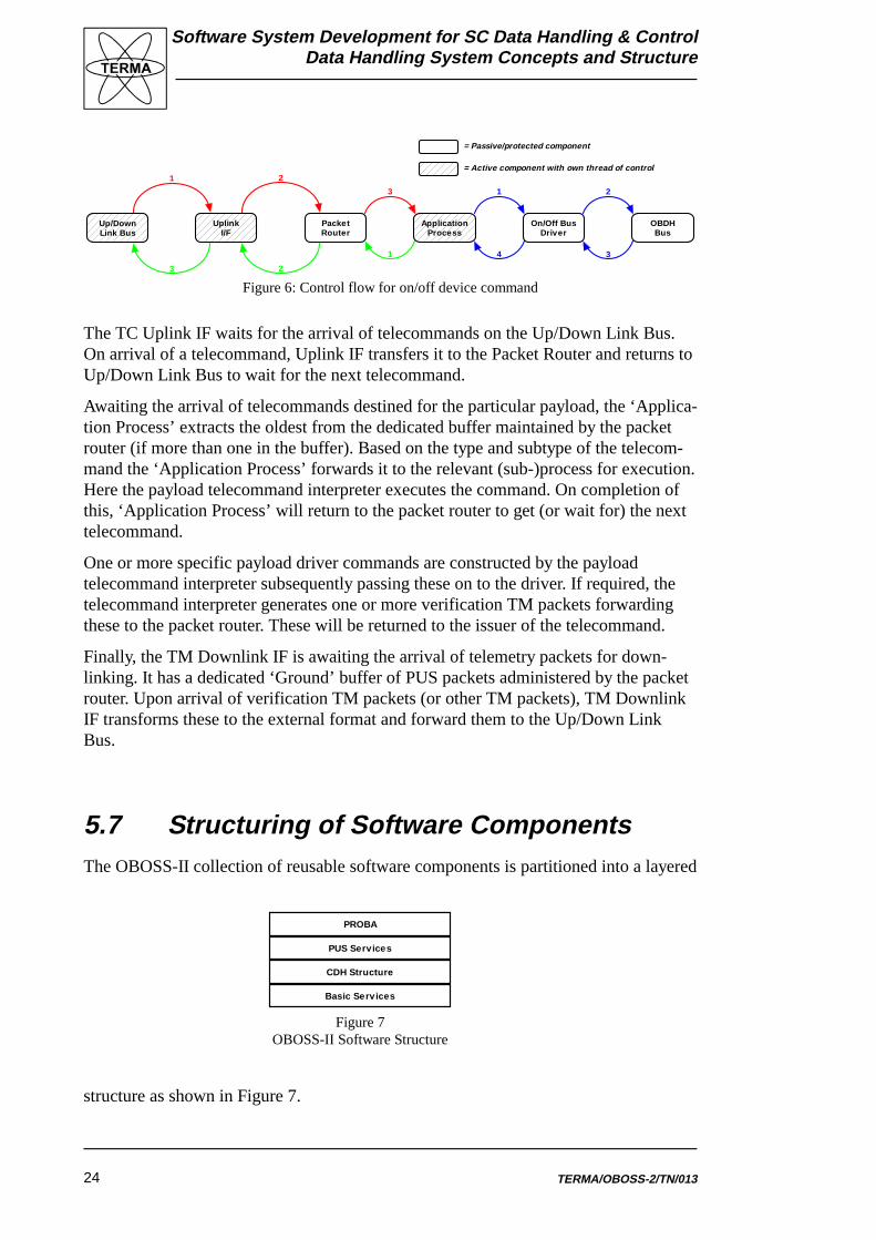
Figure 6: Control flow for on/off device command
PROBA
PUS Services
CDH Structure
Basic Services
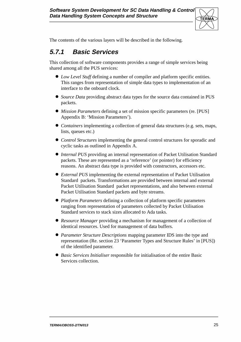
Figure 7OBOSS-II Software Structure
The TC Uplink IF waits for the arrival of telecommands on the Up/Down Link Bus.On arrival of a telecommand, Uplink IF transfers it to the Packet Router and returns toUp/Down Link Bus to wait for the next telecommand.
Awaiting the arrival of telecommands destined for the particular payload, the ‘Applica-tion Process’ extracts the oldest from the dedicated buffer maintained by the packetrouter (if more than one in the buffer). Based on the type and subtype of the telecom-mand the ‘Application Process’ forwards it to the relevant (sub-)process for execution.Here the payload telecommand interpreter executes the command. On completion ofthis, ‘Application Process’ will return to the packet router to get (or wait for) the nexttelecommand.
One or more specific payload driver commands are constructed by the payloadtelecommand interpreter subsequently passing these on to the driver. If required, thetelecommand interpreter generates one or more verification TM packets forwardingthese to the packet router. These will be returned to the issuer of the telecommand.
Finally, the TM Downlink IF is awaiting the arrival of telemetry packets for down-linking. It has a dedicated ‘Ground’ buffer of PUS packets administered by the packetrouter. Upon arrival of verification TM packets (or other TM packets), TM DownlinkIF transforms these to the external format and forward them to the Up/Down LinkBus.
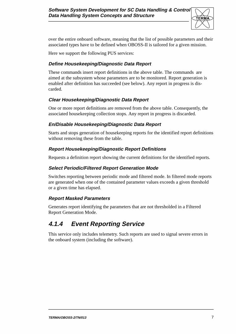
5.7 Structuring of Software ComponentsThe OBOSS-II collection of reusable software components is partitioned into a layered
structure as shown in Figure 7.
Software System Development for SC Data Handling & ControlData Handling System Concepts and Structure
TERMA/OBOSS-2/TN/013 25
The contents of the various layers will be described in the following.
5.7.1 Basic ServicesThis collection of software components provides a range of simple services beingshared among all the PUS services:
� Low Level Stuff defining a number of compiler and platform specific entities.This ranges from representation of simple data types to implementation of aninterface to the onboard clock.
� Source Data providing abstract data types for the source data contained in PUSpackets.
� Mission Parameters defining a set of mission specific parameters (re. [PUS]Appendix B: ‘Mission Parameters’).
� Containers implementing a collection of general data structures (e.g. sets, maps,lists, queues etc.)
� Control Structures implementing the general control structures for sporadic andcyclic tasks as outlined in Appendix A.
� Internal PUS providing an internal representation of Packet Utilisation Standard packets. These are represented as a ‘reference’ (or pointer) for efficiencyreasons. An abstract data type is provided with constructors, accessors etc.
� External PUS implementing the external representation of Packet UtilisationStandard packets. Transformations are provided between internal and externalPacket Utilisation Standard packet representations, and also between externalPacket Utilisation Standard packets and byte streams.
� Platform Parameters defining a collection of platform specific parametersranging from representation of parameters collected by Packet UtilisationStandard services to stack sizes allocated to Ada tasks.
� Resource Manager providing a mechanism for management of a collection ofidentical resources. Used for management of data buffers.
� Parameter Structure Descriptions mapping parameter IDS into the type andrepresentation (Re. section 23 ‘Parameter Types and Structure Rules’ in [PUS])of the identified parameter.
� Basic Services Initialiser responsible for initialisation of the entire BasicServices collection.
Software System Development for SC Data Handling & ControlData Handling System Concepts and Structure
TERMA/OBOSS-2/TN/01326
5.7.2 CDH StructureThe general framework in which application processes are to be implemented isprovided by this collection. This covers onboard routing and facilities for managementof the uplink and downlink data streams. The following components are included:
� Packet Router responsible for onboard routing of telecommands and telemetry.Implements the Onboard Traffic management Service from the Packet Utilisa-tion Standard.
� Downlink IF managing the downlink telemetry stream. Responsible for transfor-mation of PUS packets from internal to external format.
� Uplink IF managing the uplink telecommand stream. Responsible for transfor-mation of PUS packets from external to internal format.
� Up Down Link Bus implementing a telecommand byte stream and a telemetrybyte stream. Managing the interface to a telecommand decoder and telemetryframe generator (if any) including any applicable protocols.
� Dynamic Application Process Descriptors managing a ‘state’ for each applica-tion process. This includes management of source sequence counters, currentstorage selection definitions etc.
� CDH Structure Initialiser responsible for initialisation of the entire CDHStructure collection.
5.7.3 PUS ServicesThis is a collection of components each implementing a service from the packetutilisation standard. These may be combined (through instantiation) to implementapplication processes for specific missions.
� Monitor implements the onboard monitoring service from PUS.
� HK Collector provides a housekeeping and diagnostic data reporting service asdefined in PUS.
� Memory Management implementing the memory management service from thePacket Utilisation Standard.
� Storage and Retrieval implementing an onboard storage and retrieval serviceaccording to PUS.
� Event Scheduler offering services for management of a time-line of cyclicevents. Used by other components to implement e.g. periodic monitoring orhousekeeping collection.
� On Board Scheduler being an implementation of the onboard scheduling servicedefined in PUS.
� Function Management supplying a function management service according toPUS.
Software System Development for SC Data Handling & ControlData Handling System Concepts and Structure
TERMA/OBOSS-2/TN/013 27
� Event Reporting offering services for reporting of critical onboard events.
� TC Verification providing facilities for acknowledgement of telecommandexecutions according to telecommand verification service defined in PUS.
� Device Command Distribution realising a device-level commanding service asdefined in PUS.
5.7.4 PROBAThis layer contains software components implementing application processes. Theseare based on instantiations of the ‘generic’ PUS services provided in the PUS Servicescollection. At the current time only a PROBA command and data handler is includedas inspiration for future reuse. The components included in this are:
� PROBA Data Handling System - represented by the Ada main programproba_dhs.ada – combining the application processes implemented by onboardlogistics, electrical subsystem IF, and telemetry store into one piece of command& data handling software.
� Attitude Control System implementing an example of an application process foran attitude control system. Contains instances of the following Packet UtilisationStandard services:
* Device Level Commanding
* Onboard Monitoring
* Housekeeping & Diagnostics Data Reporting Service
* Function Management
� Electrical Power Subsystem implementing an example of an application processassociated to an electrical power subsystem – also known as the power distribu-tion unit. The following services from the Packet Utilisation Standard areprovided by the application process:
* Onboard Monitoring
* Housekeeping & Diagnostics Data Reporting Service
* Function Management
� Memory Manager showing a possible implementation of one centralisedmemory management service.
� Onboard Storage Administrator providing a centralised onboard storage andretrieval service.
� Telecommand Scheduler implementing an onboard scheduling service.
Software System Development for SC Data Handling & ControlData Handling System Concepts and Structure
TERMA/OBOSS-2/TN/01328
Appendix A
General Control Flows
Software System Development for SC Data Handling & ControlData Handling System Concepts and Structure
TERMA/OBOSS-2/TN/013 29
Software System Development for SC Data Handling & ControlData Handling System Concepts and Structure
TERMA/OBOSS-2/TN/01330
A.1 Hard Real-Time Control Flows
In order to enable a schedulability analysis of the resulting data handling systemsoftware are the following types of control flows used in the implementation:
� Sporadic Tasks
� Cyclic Tasks
� Protected Objects
The implementation of each of these types of tasks are outlined below.
Software System Development for SC Data Handling & ControlData Handling System Concepts and Structure
TERMA/OBOSS-2/TN/013 31
task … is
entry Go;
entry Start;
end … ;
task body … is
…
begin
accept Go ;
loop
accept Start;
! — The list of actions
end loop;
end … ;
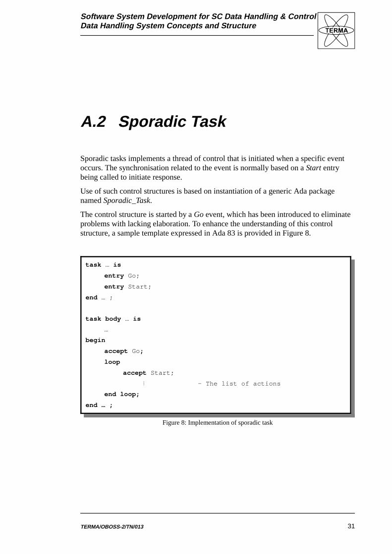
Figure 8: Implementation of sporadic task
A.2 Sporadic Task
Sporadic tasks implements a thread of control that is initiated when a specific eventoccurs. The synchronisation related to the event is normally based on a Start entrybeing called to initiate response.
Use of such control structures is based on instantiation of a generic Ada packagenamed Sporadic_Task.
The control structure is started by a Go event, which has been introduced to eliminateproblems with lacking elaboration. To enhance the understanding of this controlstructure, a sample template expressed in Ada 83 is provided in Figure 8.
Software System Development for SC Data Handling & ControlData Handling System Concepts and Structure
TERMA/OBOSS-2/TN/01332
task … isentry Go;
end … ; ’
task body … is Next_Time : System_Clock.Time; begin accept Go; Next_Time := System_Clock.System_Start_Time + Period; loop System_Clock.Delay_Until(Next_Time); Next_Time := Next_Time + Period;
! -- Cyclic Operation end loop; end … ;
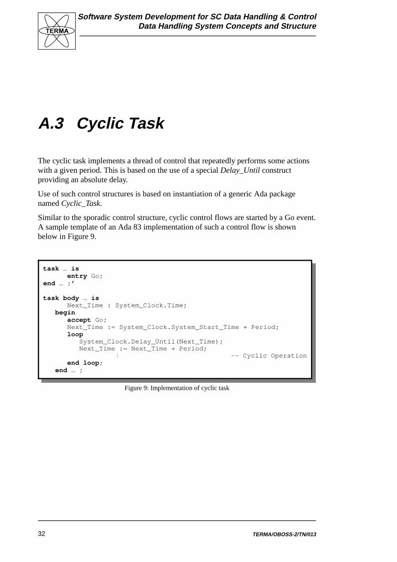
Figure 9: Implementation of cyclic task
A.3 Cyclic Task
The cyclic task implements a thread of control that repeatedly performs some actionswith a given period. This is based on the use of a special Delay_Until constructproviding an absolute delay.
Use of such control structures is based on instantiation of a generic Ada packagenamed Cyclic_Task.
Similar to the sporadic control structure, cyclic control flows are started by a Go event.A sample template of an Ada 83 implementation of such a control flow is shownbelow in Figure 9.

Software System Development for SC Data Handling & ControlData Handling System Concepts and Structure
TERMA/OBOSS-2/TN/013 33
task … is pragma PASSIVE( … );
entry … ; !entry … ;
end … ;
task body … is begin loop select accept … ( … ) do
!
end … ; or
accept … ( … ) do!
end … ; or
!
or accept terminate;
end select; end loop ; end … ;
Figure 10: Implementation of protected object
A.4 Protected Object
This object is to provide a critical region typically protecting the state of a sharedabstract data type. Its implementation is based on the passive tasks provided in theALSYS run-time system for the ERC32 cross-compiler.
Protected objects does not have a Go entry as they contain no ‘thread of control’. Thegeneral structure of such an objet is as outlined in Figure 10 below.