Embed Size (px)
Citation preview

Printed:11/19/98 4:16 PM By:SCEA Filename:final44Dataconv.doc Last saved by:SONY On:11/19/98 3:28 PM Comments: Master Copy, TechRef Release 4.3.
Data Conversion Utilities

Printed:11/19/98 4:16 PM By:SCEA Filename:final44Dataconv.doc Last saved by:SONY On:11/19/98 3:28 PM Comments: Master Copy, TechRef Release 4.3.
© 1998 Sony Computer Entertainment Inc.
Publication date: November 1998
Sony Computer Entertainment America919 E. Hillsdale Blvd., 2nd floorFoster City, CA 94404
Sony Computer Entertainment EuropeWaverley House7-12 Noel StreetLondon W1V 4HH, England
The Data Conversion Utilities manual is supplied pursuant to and subject to the terms of the SonyComputer Entertainment PlayStation® License and Development Tools Agreements, the LicensedPublisher Agreement and/or the Licensed Developer Agreement.
The Data Conversion Utilities manual is intended for distribution to and use by only Sony ComputerEntertainment licensed Developers and Publishers in accordance with the PlayStation® License andDevelopment Tools Agreements, the Licensed Publisher Agreement and/or the Licensed DeveloperAgreement.
Unauthorized reproduction, distribution, lending, rental or disclosure to any third party, in whole or in part,of this book is expressly prohibited by law and by the terms of the Sony Computer EntertainmentPlayStation® License and Development Tools Agreements, the Licensed Publisher Agreement and/or theLicensed Developer Agreement.
Ownership of the physical property of the book is retained by and reserved by Sony ComputerEntertainment. Alteration to or deletion, in whole or in part, of the book, its presentation, or its contents isprohibited.
The information in the Data Conversion Utilities manual is subject to change without notice. The content ofthis book is Confidential Information of Sony Computer Entertainment.
PlayStation and PlayStation logos are registered trademarks of Sony Computer Entertainment Inc. All othertrademarks are property of their respective owners and/or their licensors.
Printed:11/19/98 4:16 PM By:SCEA Filename:final44Dataconv.doc Last saved by:SONY On:11/19/98 3:28 PM Comments: Master Copy, TechRef Release 4.3.
Data Conversion Utilities
Table of Contents
About This Manual viiChanges Since Last Release viiRelated Documentation viiDeveloper Reference Series viiTypographic Conventions viiiDeveloper Support viii
Chapter 1: Video Data Conversion UtilitiesOverview 1-3mc32: PlayStation Movie Converter 1-4MovConv: PlayStation Movie Converter 1-49MovPack: Packs multiple streaming/audio data sets into single pack 1-67
Chapter 2: 3D Graphic Conversion UtilitiesDXF2RSD: Converts DXF to RSD 2-3DXF2RSDW: Converts DXF to RSD (Windows version) 2-10LABP: Converts Labp-formatted file to binary data 2-16MESHCONV: Creates MSH file for RSD extension 2-19MIMEFILT: Creates MIMe difference file from TMD 2-21MIMESORT: Sorts TMD Vertex Information 2-23MKMIME: Makes MIMe for HMD 2-25MKTOD: Makes TOD from PRJ and HRC files 2-27RSD2DXF: Converts RSD to DXF 2-30RSD2HMD: Converts RSD to HMD 2-31RSDCAT: Links multiple RSD files to create new RSD file set 2-33RSDFORM: Deforms or moves RSD data 2-35RSDLINK: Converts RSD to TMD 2-39RSDUP: Converts old RSD file to HMD-compatible RSD file 2-45TMD2PMD: Converts TMD to PMD 2-47TMDSORT/INFO: Sorts and displays TMD files 2-49XHMD: Converts an HMD data file to labp format 2-50
Chapter 3: 2D Graphics Conversion UtilitiesBMP2TIM: Converts BMP to TIM 3-3PICT2TIM: Converts PICT to TIM 3-4RGB2TIM: Converts RGB to TIM 3-5TIMTOOL 3-6TIM2BMP: Converts TIM to BMP 3-10TIMPOS: Changes VRAM in TIM 3-11TIMUTIL: Allows multiple TIM, BMP, PICT and RGB conversions 3-12TIMEXP: Plug-in for use with Photoshop 2.5 and 3.0 3-22TIMexpE: Plug-in for use with Photoshop 4.0, Windows or Artist Board 3-25TIMfmtE: Plug-in for use with Photoshop 4.0, Windows 95 or NT 3-32TIMFMT/TIMformatE: Plug-ins for use with Photoshop 2.5 and 3.0 3-37MGAME.ADDIN: Plug-in for Alias Wavefront 3-42TOD_I.KXP: Plug-in for 3D Studio 3-57Plug-ins for LightWave 3D 4.0 3-64
Chapter 4: Sound Conversion UtilitiesSMF2SEQ: Creates Sequence Data (Mac version) 4-3SMF2SEQ: Creates Sequence Data (PC version) 4-5AIFF2VAG: Creates Waveform Data (Mac version) 4-6AIFF2VAG: Creates Waveform Data (PC version) 4-8MKVAB: Makes VAB 4-9SEQ2SEP: Converts SEQ to SEP 4-11
iv Table of Contents
Printed:11/19/98 4:16 PM By:SCEA Filename:final44Dataconv.doc Last saved by:SONY On:11/19/98 3:28 PM Comments: Master Copy, TechRef Release 4.3.
Data Conversion Utilities
VABSPLIT: Splits VAB into VH and VB 4-12
List of Figures
Figure 1-1: Main Window 1-6Figure 1-2: Conversion Window 1-7Figure 1-3: Video+Sound Window 1-8Figure 1-4: Multi Channel Window 1-10Figure 1-5: MDEC Parameters Window 1-12Figure 1-6 : MDEC Parameter - Q Matrix Window 1-14Figure 1-7: XA Parameters Window 1-14Figure 1-8: Script Window 1-15Figure 1-9: Video Window 1-16Figure 1-10: Sound Window 1-17Figure 1-11: General Setting Dialog Box 1-17Figure 1-12: Video Data Creation Procedure 1-18Figure 1-13: Sound Data Creation Procedure 1-21Figure 1-14: Ordinary Streaming 1-22Figure 1-15: Multi-channel Streaming 1-22Figure 1-16: Efficient use of CD-ROM storage with multiple channels 1-23Figure 1-17: Procedure for creating multi-channel data 1-23Figure 1-18: MovConv Main Window 1-50Figure 1-19: Preview Dialog Box 1-51Figure 1-20: MDEC Parameters Dialog Box 1-51Figure 1-21: Preview MDEC Image Dialog Box 1-53Figure 1-22: Q Matrix Dialog Box 1-54Figure 1-23: XA Audio Parameters Dialog Box 1-54Figure 1-24: AVI Parameters Dialog Box 1-55Figure 1-25: Interleave Video with Audio Dialog Box 1-55Figure 1-26: Script Dialog Box 1-57Figure 1-27: MovPack 1-67Figure 2-1: Conversion of Coordinate Systems 2-4Figure 2-2: Information Dialog 2-11Figure 2-3: Information Dialog 2-13Figure 2-4: File Open Dialog 2-14Figure 2-5: File Save Dialog 2-14Figure 2-6: Undefined Color Dialog 2-15Figure 2-7: VDF File Format 2-22Figure 3-1: Parameter Setting Window 3-14Figure 3-2: TIM Display Dialog 3-16Figure 3-3: File Open Dialog 3-16Figure 3-4: File Save Dialog 3-17Figure 3-5: Directory Select Dialog 3-18Figure 3-6: Set Dialog 3-18Figure 3-7: TIM Locate Dialog 3-19Figure 3-8: VRAM Image Area 3-19Figure 3-9: Information Area 3-20Figure 3-10: Select List Area 3-20Figure 3-11: Menu Bar 3-20Figure 3-12: TIM Export Options Dialog Box 3-23Figure 3-13: TIM Export Options Dialog Box 3-28Figure 3-14: TIM Format Output Options Dialog Box 3-34Figure 3-15: "Open" Dialog Box 3-38Figure 3-16: "Open in Specified Format" Dialog Box 3-38Figure 3-17: "Save with another Name" Dialog Box 3-39Figure 3-18: Warning about Image Information which cannot be Saved 3-39
Table of Contents v
Printed:11/19/98 4:16 PM By:SCEA Filename:final44Dataconv.doc Last saved by:SONY On:11/19/98 3:28 PM Comments: Master Copy, TechRef Release 4.3.
Data Conversion Utilities
Figure 3-19: TIM Format Output Options dialog box 3-40Figure 3-20: Opening the Plug-in Manager window 3-42Figure 3-21: Search path and file name window 3-42Figure 3-22: Plug-in Manager window 3-43Figure 3-23: Opening the Make Game translator window 3-43Figure 3-24: Make Game translator window 3-44Figure 3-25: PlayStation Export window 3-45Figure 3-26: TMD File option 3-45Figure 3-27: Video RAM Mapper window 3-47Figure 3-28: Screen Size Menus 3-48Figure 3-29: Load Map File window 3-48Figure 3-30: Textures section 3-49Figure 3-31: Options Section 3-50Figure 3-32: Animation Section 3-50Figure 4-1: SMF Output in Performer 4-3Figure 4-2: SMF2SEQ 4-4Figure 4-3: SMF2SEQ Icon 4-4Figure 4-4: AIFF Output in SoundDesignerII 4-6Figure 4-5: AIFF2VAG Conversion File 4-6Figure 4-6: AIFF2VAG Icon 4-7Figure 4-7: ADSR rates 4-10
List of Tables
Table 1-1: Movie Tools 1-3Table 1-2: Formats Supported by mc32 1-4Table 1-3: Setting the Total Number of Channels for XA Sound 1-11Table 1-4: Type of conversion as a function of input data and output format settings 1-12Table 1-5: Setting leap sectors 1-13Table 1-6: Script Functions 1-25Table 1-7: Conversion Differences as a Function of Audio 1-52Table 1-8: Leap Sector Setting 1-52Table 1-9: List of Scripting Functions 1-59Table 1-10: Settings for the total number of channels in XA audio data 1-68Table 2-1: Commercial 3D modelers convertible with DXF2RSD 2-5Table 2-2: Currently unconvertible commercial 3D modelers 2-6Table 2-3: RSD o TMD Conversion Comparison Table 2-41Table 3-1: Parameters specifiable in the [DefaultValue] section of TIMexp.ini 3-27Table 3-2: Parameters specifiable in the [DefaultValue] section of TIMfmt.ini 3-33Table 3-3: Controlling the STP bit of the color entries 3-49Table 3-4: GetPlayStation Options 3-51Table 4-1: Appropriate Format (SMF) 4-3Table 4-2: VabHdr 4-9Table 4-3: ProgAtr 4-9Table 4-4: VagAtr 4-10

vi Table of Contents
Printed:11/19/98 4:16 PM By:SCEA Filename:final44Dataconv.doc Last saved by:SONY On:11/19/98 3:28 PM Comments: Master Copy, TechRef Release 4.3.
Data Conversion Utilities
Printed:11/19/98 4:16 PM By:SCEA Filename:final44Dataconv.doc Last saved by:SONY On:11/19/98 3:28 PM Comments: Master Copy, TechRef Release 4.3.
Data Conversion Utilities
About This Manual
This manual is the latest release of documentation for PlayStation® Data Conversion Utilities as ofRun-Time Library 4.4. This document is a compilation of all available file conversion information. Somesections may also exist as individual documents within the Developer Reference Series. The purpose of thismanual is to provide a single authoritative reference to PlayStation® Data Conversion Utilities.
Changes Since Last Release
xý PC versions of two sound converters: smf2seq and aiff2vag have been added to the existing Macversion descriptions.
xý The release history and revision number information in XHMD and MKMIME have been updated.
xý A path change was made in LABP to match changes in SDevTC.
Related Documentation
The following volumes in the Developer Reference Series also contain file format information:
x File Formatsx 3D Graphics Toolx Sound Artist Tool
Developer Reference Series
This manual is part of the Developer Reference Series, a series of technical reference volumes covering allaspects of PlayStation development. The complete series is listed below:
Manual Description
PlayStation Hardware Describes the PlayStation hardware architectureand overviews its subsystems.
PlayStation Operating System Describes the PlayStation operating system andrelated programming fundamentals.
Run-Time Library Overview Describes the structure and purpose of therun-time libraries provided for PlayStation softwaredevelopment.
Run-Time Library Reference Defines all available PlayStation run-time libraryfunctions, macros and structures.
Inline Programming Reference Describes in-line programming using DMPSX, GTEinline macro and GTE register information.
SDevTC Development Environment Describes the SDevTC (formerly "Psy-Q")Development Environment for PlayStation softwaredevelopment.
3D Graphics Tools Describes how to use the PlayStation 3D GraphicsTools, including the animation and material editors.
Sprite Editor Describes the Sprite Editor tool for creating spritedata and background picture components.
Sound Artist Tool Provides installation and operation instructions forthe DTL-H800 Sound Artist Board and explainshow to use the Sound Artist Tool software.
File Formats Describes all native PlayStation data formats.

viii About This Manual
Printed:11/19/98 4:16 PM By:SCEA Filename:final44Dataconv.doc Last saved by:SONY On:11/19/98 3:28 PM Comments: Master Copy, TechRef Release 4.3.
Data Conversion Utilities
Data Conversion Utilities Describes all available PlayStation data conversionutilities, including both stand-alone and plug-inprograms.
CD Emulator Provides installation and operation instructions forthe CD Emulator subsystem and related software.
CD-ROM Generator Describes how to use the CD-ROM Generatorsoftware to write CD-R discs.
Performance Analyzer User Guide Provides general instructions for using thePerformance Analyzer software.
Performance Analyzer Technical Reference Describes how to measure software performanceand interpret the results using the PerformanceAnalyser.
DTL-H2000 Installation and Operation Provides installation and operation instructions forthe DTL-H2000 Development System.
DTL-H2500/2700 Installation and Operation Provides installation and operation instructions forthe DTL-H2500/H2700 Development Systems.
Typographic Conventions
Certain Typographic Conventions are used through out this manual to clarify the meaning of the text. Thefollowing conventions apply to all narrative text except for structure and function descriptions:
Convention Meaning
courier Indicates literal program code.
Bold Indicates a document, chapter or section title.
The following conventions apply within structure and function descriptions only:
Convention Meaning
Medium Bold Denotes structure or function types and names.
Italic Denotes function arguments and structure members.
Developer Support
Sony Computer Entertainment America (SCEA)Sony Computer Entertainment America (SCEA)Sony Computer Entertainment America (SCEA)Sony Computer Entertainment America (SCEA)
SCEA developer support is available to licensees in North America only. You may obtain developer supportor additional copies of this documentation by contacting the following addresses:
Order Information Developer Support
In North AmericaIn North AmericaIn North AmericaIn North America In North AmericaIn North AmericaIn North AmericaIn North AmericaAttn: Developer Tools Coordinator E-mail: [email protected] Computer Entertainment America Web: http://www.scea.sony.com/dev919 East Hillsdale Blvd., 2nd floor Developer Support Hotline: (650) 655-8181Foster City, CA 94404 (Call Monday through Friday, 8 a.m. to 5 p.m.,Tel: (650) 655-8000 PST/PDT)
About This Manual ix
Printed:11/19/98 4:16 PM By:SCEA Filename:final44Dataconv.doc Last saved by:SONY On:11/19/98 3:28 PM Comments: Master Copy, TechRef Release 4.3.
Data Conversion Utilities
Sony Computer Entertainment Europe (SCEE)Sony Computer Entertainment Europe (SCEE)Sony Computer Entertainment Europe (SCEE)Sony Computer Entertainment Europe (SCEE)
SCEE developer support is available to licensees in Europe only. You may obtain developer support oradditional copies of this documentation by contacting the following addresses:
Order Information Developer Support
In EuropeIn EuropeIn EuropeIn Europe In EuropeIn EuropeIn EuropeIn EuropeAttn: Production Coordinator E-mail: [email protected] Computer Entertainment Europe Web: https://www-s.playstation.co.ukWaverley House Developer Support Hotline:7-12 Noel Street +44 (0) 171 447 1680London W1V 4HH (Call Monday through Friday, 9 a.m. to 6 p.m.,Tel: +44 (0) 171 447 1600 GMT or BST/BDT)

x About This Manual
Printed:11/19/98 4:16 PM By:SCEA Filename:final44Dataconv.doc Last saved by:SONY On:11/19/98 3:28 PM Comments: Master Copy, TechRef Release 4.3.
Data Conversion Utilities

Printed:11/19/98 4:16 PM By:SCEA Filename:final44Dataconv.doc Last saved by:SONY On:11/19/98 3:28 PM Comments: Master Copy, TechRef Release 4.3.
Data Conversion Utilities
Chapter 1:Video Data Conversion Utilities

1-2 Video Data Conversion Utilities
Printed:11/19/98 4:16 PM By:SCEA Filename:final44Dataconv.doc Last saved by:SONY On:11/19/98 3:28 PM Comments: Master Copy, TechRef Release 4.3.
Data Conversion Utilities
Video Data Conversion Utilities 1-3
Printed:11/19/98 4:16 PM By:SCEA Filename:final44Dataconv.doc Last saved by:SONY On:11/19/98 3:28 PM Comments: Master Copy, TechRef Release 4.3.
Data Conversion Utilities
Overview
The PlayStation can successively read and process data from the CD-ROM. This operation is known as“streaming”, and is commonly used to play back video and sound. For processing video, the PlayStationuses a frame-based compressed video format that is JPEG-compatible. During playback, eachcompressed frame is expanded using the MDEC, the PlayStation's image expansion chip, and theexpanded frame is presented on the display. In a similar manner, sound processing is performed with CD-ROM XA compression. During playback, sound is reproduced using the PlayStation’s CD-ROM XAdecoder.
Utilities called movie tools compress and format video and sound data into formats suitable for use by thePlayStation's hardware and libraries. Conventional movie tools such as movconv and movpack areavailable for Windows 3.1 and Windows 95. The new movie converter, mc32, which runs under Windows95 and Windows NT, integrates these functions and provides much faster image compression.
The next section describes the functionality and use of mc32. The previous movie tools, movconv andmovpack, are described in subsequent sections.
Table 1-1: Movie Tools
Program name Functions, environment
mc32.exe Compression of video and sound dataFormat conversionMultichannel interleave(Windows 95/NT)
Movconv.exe Compression of video and sound dataFormat conversion(Windows 3.1/95)
Movpack.exe Multichannel interleave(Windows 3.1/95)
1-4 Video Data Conversion Utilities
Printed:11/19/98 4:16 PM By:SCEA Filename:final44Dataconv.doc Last saved by:SONY On:11/19/98 3:28 PM Comments: Master Copy, TechRef Release 4.3.
Data Conversion Utilities
mc32: PlayStation Movie Converter
Overview
Features
mc32 provides video compression and sound compression, format conversion, multiple channel creation,video/sound synthesis, script execution, and other functions.
During video compression, various parameters such as the frame rate must be specified. With mc32, theseparameters can be selected while simultaneously verifying the quality of the compressed image. mc32 alsosupports a simple scripting language which allows batch conversion of multiple data items.
Functions
mc32 performs the following five functions:
x Video conversionx Sound conversionx Video/sound synthesisx Creation of multiple channels of datax Script execution
Supported Formats
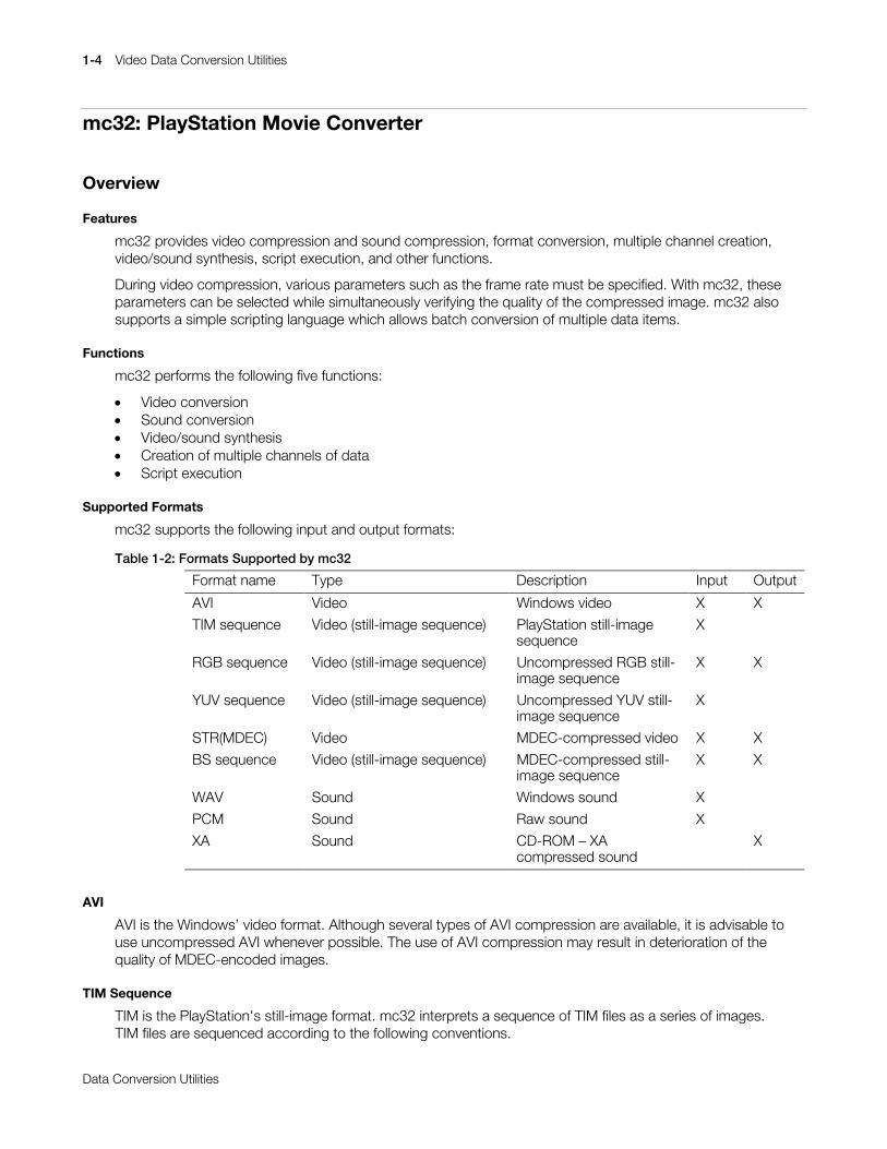
mc32 supports the following input and output formats:
Table 1-2: Formats Supported by mc32
Format name Type Description Input Output
AVI Video Windows video X X
TIM sequence Video (still-image sequence) PlayStation still-imagesequence
X
RGB sequence Video (still-image sequence) Uncompressed RGB still-image sequence
X X
YUV sequence Video (still-image sequence) Uncompressed YUV still-image sequence
X
STR(MDEC) Video MDEC-compressed video X X
BS sequence Video (still-image sequence) MDEC-compressed still-image sequence
X X
WAV Sound Windows sound X
PCM Sound Raw sound X
XA Sound CD-ROM – XAcompressed sound
X
AVI
AVI is the Windows’ video format. Although several types of AVI compression are available, it is advisable touse uncompressed AVI whenever possible. The use of AVI compression may result in deterioration of thequality of MDEC-encoded images.
TIM Sequence
TIM is the PlayStation's still-image format. mc32 interprets a sequence of TIM files as a series of images.TIM files are sequenced according to the following conventions.

Video Data Conversion Utilities 1-5
Printed:11/19/98 4:16 PM By:SCEA Filename:final44Dataconv.doc Last saved by:SONY On:11/19/98 3:28 PM Comments: Master Copy, TechRef Release 4.3.
Data Conversion Utilities
...
...
xx0017.TIM
xx0018.TIM
xx0019.TIM
xx0020.TIM
...
...
(xx is any character string, and there need not be four numeric digits.)
To specify a TIM sequence, specify the name of the file corresponding to the first frame. Once the firstframe is specified, the files corresponding to this and subsequent frames are retrieved automatically fromthe same directory. The collection of frames is handled as a series of images.
RGB Sequence
RGB is a 24-bit direct color format. Each pixel in RGB is represented by 8 bits of red, 8 bits of green and 8bits of blue. The pixels are ordered such that the first pixel is in the upper-left corner and the last pixel is inthe lower-right corner.
Width and height are not represented in the RGB format. When an RGB file is specified, mc32 will requestthat the width and height also be specified. The file naming conventions and specification method for theRGB format are the same as those for the TIM sequence.
YUV Sequence
The YUV (422) format orders the luminance (Y) and two color difference components (Cb, Cr) as follows:
Cb12, Y1, Cr12, Y2, Cb34, Y3, Cr34, Y4 ....
Each component includes an 8-bit gradation. In addition, the same color-difference data is shared by twoadjacent pixels, so the horizontal resolution of the color difference component is one-half the horizontalresolution of the luminance component.
Width and height are not represented in the YUV format. When a YUV file is specified, mc32 will requestthat the width and height also be specified. The file naming conventions and specification method for theYUV format are the same as those for the TIM sequence.
STR(MDEC)
STR(MDEC) is an STR format with each frame MDEC-compressed. The format of each STR(MDEC) frameis the same as that of the BS format.
BS Sequence
BS is an MDEC-compressed still image format. Width and height are not represented in the BS format. Thefile naming conventions and specification method for the BS format are identical to those for the TIMsequence.
WAV
WAV is the Windows’ sound format. In mc32, WAV is equivalent to a PCM format with samplingfrequencies of 44 KHz / 22 KHz / 11 KHz and a sample length of 16 bits.
PCM
PCM is an uncompressed sound format. It can be used with data having a 16-bit sample length.

1-6 Video Data Conversion Utilities
Printed:11/19/98 4:16 PM By:SCEA Filename:final44Dataconv.doc Last saved by:SONY On:11/19/98 3:28 PM Comments: Master Copy, TechRef Release 4.3.
Data Conversion Utilities
XA
XA is a format for ADPCM compression in accordance with the CD-ROM XA standard. The samplingfrequencies of XA are 37.8 KHz and 19.8 KHz, corresponding to stereo and monaural, respectively.
mc32 Operation
This section describes the basic operation of mc32. For GUI-based operation, the use of each window anddialog box is described in detail below.
Main Window
Figure 1-1: Main Window
Conversion window Mdec Parameters – Q Matrix window
Script windowMulti Channel window
Sound window
Mdec Parameters window
Xa Parameters window
Video+Sound windowVideo window

Video Data Conversion Utilities 1-7
Printed:11/19/98 4:16 PM By:SCEA Filename:final44Dataconv.doc Last saved by:SONY On:11/19/98 3:28 PM Comments: Master Copy, TechRef Release 4.3.
Data Conversion Utilities
Figure 1-13 shows the Main window of mc32, the initial window that is displayed after starting mc32. Fromthe Main window, the following child windows can be opened from the View menu, from the File/Openmenu, or by using the toolbar:
x Conversion windowx Video+Sound windowx Multi Channel windowx Mdec Parameters windowx Mdec Parameter - Q Matrix windowx Xa Parameters windowx Script windowx Video windowx Sound window
Conversion Window
Figure 1-2: Conversion Window
Output referencebutton
Input referencebutton
Conversiongauge
Output format nameInput format name
Output filenameInput filename
The Conversion window is used to perform Video MDEC compression and sound CD-ROM XAcompression. MDEC expansion can also be performed by specifying a compressed image as input. TheConversion window can be opened from the View/Conversion menu or by using the Conversion button onthe toolbar. The Conversion window is also displayed in the Main window after mc32 is started.
x Specifying the Input FilenameSpecifying the Input FilenameSpecifying the Input FilenameSpecifying the Input FilenameThe input filename is specified by clicking the input reference button ([...] button on the left) andopening the File Open dialog box. The input filename can also be entered directly in the Filename textbox on the left. When a file is specified with the input reference button, the specified file is displayed inthe Video window. This allows the contents of the input file to be verified prior to conversion.
x Specifying the Input FormatSpecifying the Input FormatSpecifying the Input FormatSpecifying the Input FormatThe input format is inferred from the input filename extension and is selected automatically. The inputformat can also be selected from the Format list on the left side of the window.
x Specifying the Output FilenameSpecifying the Output FilenameSpecifying the Output FilenameSpecifying the Output FilenameThe output filename is inferred from the input filename and the output format, and is automaticallydisplayed. The output filename can be changed by clicking the output reference button ([...] button onthe right). This will open the Save File dialog box and allow the output filename to be selected. Theoutput filename can also be entered directly in the Filename text box on the right side of the window.
x Specifying the Output FormatSpecifying the Output FormatSpecifying the Output FormatSpecifying the Output FormatThe output format can be selected from the Format list on the right side of the window.
1-8 Video Data Conversion Utilities
Printed:11/19/98 4:16 PM By:SCEA Filename:final44Dataconv.doc Last saved by:SONY On:11/19/98 3:28 PM Comments: Master Copy, TechRef Release 4.3.
Data Conversion Utilities
x Setting the Output ParametersSetting the Output ParametersSetting the Output ParametersSetting the Output ParametersAfter selecting the output format, the output parameters can be selected by clicking the Attributesbutton. This will open the parameter window for the selected output format. There are two parameterwindows: the MDEC Parameters window for MDEC compression and the XA Parameters window forsound compression. These windows can also be opened from the View menu or by using thecorresponding button on the toolbar.
x ConversionConversionConversionConversionOnce all settings have been made, the conversion operation can be started by clicking the Go button.The conversion parameter values set in the parameters window are used during conversion, however,changes in their values will not be reflected in the conversion. Progress is displayed by a gauge duringconversion . The conversion operation can be cancelled by clicking the Cancel button.
Video+Sound Window
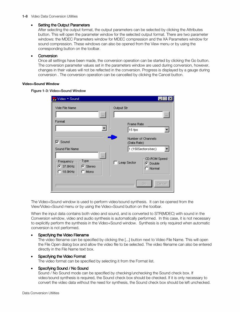
Figure 1-3: Video+Sound Window
The Video+Sound window is used to perform video/sound synthesis. It can be opened from theView/Video+Sound menu or by using the Video+Sound button on the toolbar.
When the input data contains both video and sound, and is converted to STR(MDEC) with sound in theConversion window, video and audio synthesis is automatically performed. In this case, it is not necessaryto explicitly perform the synthesis in the Video+Sound window. Synthesis is only required when automaticconversion is not performed.
x Specifying the Video FilenameSpecifying the Video FilenameSpecifying the Video FilenameSpecifying the Video FilenameThe video filename can be specified by clicking the [...] button next to Video File Name. This will openthe File Open dialog box and allow the video file to be selected. The video filename can also be entereddirectly in the File Name text box.
x Specifying the Video FormatSpecifying the Video FormatSpecifying the Video FormatSpecifying the Video FormatThe video format can be specified by selecting it from the Format list.
x Specifying Sound / No SoundSpecifying Sound / No SoundSpecifying Sound / No SoundSpecifying Sound / No SoundSound / No Sound mode can be specified by checking/unchecking the Sound check box. Ifvideo/sound synthesis is required, the Sound check box should be checked. If it is only necessary toconvert the video data without the need for synthesis, the Sound check box should be left unchecked.

Video Data Conversion Utilities 1-9
Printed:11/19/98 4:16 PM By:SCEA Filename:final44Dataconv.doc Last saved by:SONY On:11/19/98 3:28 PM Comments: Master Copy, TechRef Release 4.3.
Data Conversion Utilities
For example, when converting a BS sequence to STR(MDEC), the Sound check box should not bechecked.
x Specifying the Sound FilenameSpecifying the Sound FilenameSpecifying the Sound FilenameSpecifying the Sound FilenameAfter selecting the sound mode, the sound filename can be specified by clicking the [...] button next toSound File Name. This will open the File Open dialog box and allow the sound filename to be selected.The sound filename can also be entered directly in the File Name text box.
x Setting the Frequency and Stereo/Monaural ModeSetting the Frequency and Stereo/Monaural ModeSetting the Frequency and Stereo/Monaural ModeSetting the Frequency and Stereo/Monaural ModeAfter selecting the sound mode, the frequency and stereo / monaural mode can be selected. Theattributes of the specified sound file should be selected and must match those of the actual file,otherwise video/audio synthesis will not be performed correctly.
x Setting the CD-ROM SpeedSetting the CD-ROM SpeedSetting the CD-ROM SpeedSetting the CD-ROM SpeedThe CD-ROM speed can be selected as Double speed or Normal speed in the CD-ROM Speed group.
x Setting Leap SectorsSetting Leap SectorsSetting Leap SectorsSetting Leap SectorsLeap Sectors are set by checking the Leap Sector check box. See the description under the MDECParameters window on how to determine if leap sectors are required.
x Selecting the Frame RateSelecting the Frame RateSelecting the Frame RateSelecting the Frame RateThe frame rate can be selected from the Frame Rate list. This value must agree with the frame rate ofthe video file as frame rate conversion is not performed. If the selected frame rate were different fromthe original frame rate, the playback time of the video would not be correct.
x Selecting Number of ChannelsSelecting Number of ChannelsSelecting Number of ChannelsSelecting Number of ChannelsThe number of channels can be selected from the Number of Channels (Data Rate) list and is used tocreate multichannel data. Select '1' if multichannel data is not required.
x Specifying the Output FilenameSpecifying the Output FilenameSpecifying the Output FilenameSpecifying the Output FilenameThe output filename can be specified by clicking the [...] button of the Output Str. This will open the FileSave dialog box and allow the output filename to be selected. The output filename can also be entereddirectly in the Output Str text box.
x ExecutionExecutionExecutionExecutionVideo/sound synthesis can be started by clicking the Go button. Progress is displayed by a gaugeduring synthesis. The synthesis operation can be cancelled by clicking the Cancel button.
1-10 Video Data Conversion Utilities
Printed:11/19/98 4:16 PM By:SCEA Filename:final44Dataconv.doc Last saved by:SONY On:11/19/98 3:28 PM Comments: Master Copy, TechRef Release 4.3.
Data Conversion Utilities
Multi Channel Window
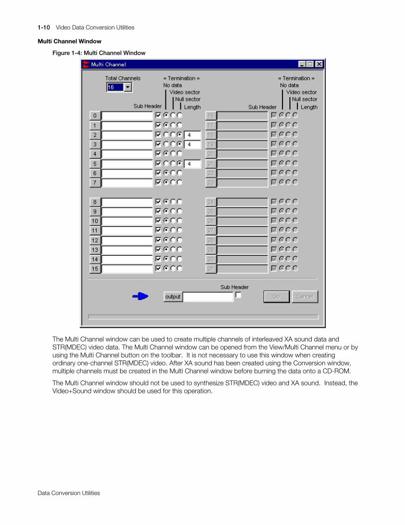
Figure 1-4: Multi Channel Window
The Multi Channel window can be used to create multiple channels of interleaved XA sound data andSTR(MDEC) video data. The Multi Channel window can be opened from the View/Multi Channel menu or byusing the Multi Channel button on the toolbar. It is not necessary to use this window when creatingordinary one-channel STR(MDEC) video. After XA sound has been created using the Conversion window,multiple channels must be created in the Multi Channel window before burning the data onto a CD-ROM.
The Multi Channel window should not be used to synthesize STR(MDEC) video and XA sound. Instead, theVideo+Sound window should be used for this operation.
Video Data Conversion Utilities 1-11
Printed:11/19/98 4:16 PM By:SCEA Filename:final44Dataconv.doc Last saved by:SONY On:11/19/98 3:28 PM Comments: Master Copy, TechRef Release 4.3.
Data Conversion Utilities
x Setting the Total Number of ChannelsSetting the Total Number of ChannelsSetting the Total Number of ChannelsSetting the Total Number of ChannelsThe total number of channels can be set from the Total Channels list. If the multichanneled data is XAsound, set the total number of channels according to the values shown in the following table.
Table 1-3: Setting the Total Number of Channels for XA Sound
Playback speed Sampling frequency Stereo/monaural Total number ofchannels
Double speed 37.8KHz Stereo 8
Double speed 37.8KHz Monaural 16
Double speed 18.9KHz Stereo 16
Double speed 18.9KHz Monaural 32
Standard speed 37.8KHz Stereo 4
Standard speed 37.8KHz Monaural 8
Standard speed 18.9KHz Stereo 8
Standard speed 18.9KHz Monaural 16
If XA sound is converted in the Conversion window then burned directly onto a CD-ROM, it will not playback correctly. To ensure correct playback, it is necessary to interleave the sound data according tothe number of channels shown in the table.
x Specifying the Input FilenameSpecifying the Input FilenameSpecifying the Input FilenameSpecifying the Input FilenameAn input channel filename must be specified for each channel. The input filenames can be specified byclicking each of the channel's buttons. This will open the File Open dialog box and allow the inputfilename to be specified. The input filename can also be entered directly in the text box.
If the number of files to be interleaved is less than the total number of channels, the extra channels maybe left blank. Any unspecified channels will be treated as empty channels. For video data, the input fileshould be specified as STR(MDEC). For sound data, the input file should be specified as XA.
x Setting the Input Subheader FlagSetting the Input Subheader FlagSetting the Input Subheader FlagSetting the Input Subheader FlagSet the subheader flag for those channels in which an input file was specified. The Sub Header checkbox should be checked if the input has either sound data or streaming data with sound. The SubHeader check box should be left unchecked if the input is video-only streaming data.
x Setting the Data TerminatorSetting the Data TerminatorSetting the Data TerminatorSetting the Data TerminatorThe data terminator that is appended to the end of each channel can be set by selecting theappropriate radio button under Termination. Normally, No data is selected. When Video sector isselected, an empty video sector is appended to the end of the channel data. Empty video sectors canbe used for creating multiple sound channels. If an empty video sector is appended to the end ofsound data, reading the video sector during playback can be used to identify the end of sound data.
Null sector can be selected to intentionally insert a space at the end of channel data. When Videosector or Null sector is specified for the data terminator, the length is specified in sectors.
x Specifying the Output FilenameSpecifying the Output FilenameSpecifying the Output FilenameSpecifying the Output FilenameThe output filename can be specified by clicking the output button. This will open the Save File dialogbox and allow the output filename to be selected. The output filename can also be specified byentering the filename directly in the text box.
x Setting the Output Data Subheader FlagSetting the Output Data Subheader FlagSetting the Output Data Subheader FlagSetting the Output Data Subheader FlagThe Output Data Sub Header check box should be checked if the output data is either streaming datawith sound or sound data. Leave the Sub Header check box unchecked if the output is video-onlystreaming data.
x InterleavingInterleavingInterleavingInterleavingInterleaving can be started by clicking the Go button. Progress is displayed by a gauge during theoperation. Interleaving can be cancelled by clicking the Cancel button.

1-12 Video Data Conversion Utilities
Printed:11/19/98 4:16 PM By:SCEA Filename:final44Dataconv.doc Last saved by:SONY On:11/19/98 3:28 PM Comments: Master Copy, TechRef Release 4.3.
Data Conversion Utilities
MDEC Parameters Window
Figure 1-5: MDEC Parameters Window
The MDEC Parameters window is used to set compression parameters for MDEC compression. Thewindow can be opened from the View/MDEC Parameters menu, or by using the MDEC Parameters buttonon the toolbar or the Attributes button in the Conversion window. The values which are specified in theMDEC Parameters window are used as conversion parameters at the start of MDEC compression in theConversion window and during MDEC compression in the Video window. If values are changed onceconversion has started, the updated values will not be reflected in the converted data. In addition to theMDEC compression parameters shown above, other parameters which can be set include the quantizationmatrix which is specified in the MDEC Parameter - Q Matrix window.
x Selecting the Output TypeSelecting the Output TypeSelecting the Output TypeSelecting the Output TypeThe output type is specified using the Sound check box in the Output Type group. Check the Soundcheck box if the output data should contain sound, and leave the box unchecked if sound should notbe included in the output. The output type indicates whether the output data should contain sound,and does not depend on whether the input data contains sound. The following table shows the type ofconversion performed as a function of input data and output format settings.
Table 1-4: Type of conversion as a function of input data and output format settings
Input data Output settings Operation
With sound With sound Video conversion, sound conversion, video/soundsynthesis
With sound Without sound Video conversion only
Without sound With sound Video conversion only. The converted video data sizedoes not include the sound component. The video andsound are converted separately, and this setting is usedlater when performing video/sound synthesis.
Without sound Without sound Video conversion only
x Selecting the Frequency and Stereo/Monaural ModeSelecting the Frequency and Stereo/Monaural ModeSelecting the Frequency and Stereo/Monaural ModeSelecting the Frequency and Stereo/Monaural ModeWhen the Sound checkbox is checked, the output sampling frequency and stereo/monaural mode canbe selected using the radio buttons in the Sound group.

Video Data Conversion Utilities 1-13
Printed:11/19/98 4:16 PM By:SCEA Filename:final44Dataconv.doc Last saved by:SONY On:11/19/98 3:28 PM Comments: Master Copy, TechRef Release 4.3.
Data Conversion Utilities
x Selecting Easy Settings or Custom SettingsSelecting Easy Settings or Custom SettingsSelecting Easy Settings or Custom SettingsSelecting Easy Settings or Custom SettingsEasy Settings and Custom Settings are two methods for setting parameters in the MDEC Parameterswindow.
When Easy Settings is selected, the size of each frame after compression is determined automaticallyfrom parameters such as the CD-ROM playback speed, frame rate and number of channels. EasySettings should be used when the size of the compressed image does not need to be controlled.
When Custom Settings is selected, the maximum amount of storage used by the compressed imagecan be specified. This is useful when compressing still images or individual frames of video that needto be smaller than a certain size. When the output data contains sound, only Easy Settings can beused.
Check the Easy check box to select Easy Settings. Check the Custom check box to select CustomSettings.
x Selecting the CD-ROM Playback SpeedSelecting the CD-ROM Playback SpeedSelecting the CD-ROM Playback SpeedSelecting the CD-ROM Playback SpeedIf Easy Settings is selected, the radio buttons in the CD-ROM Speed group can be used to selectdouble speed or standard speed.
x Selecting the Frame RateSelecting the Frame RateSelecting the Frame RateSelecting the Frame RateIf Easy Settings is selected, an appropriate frame rate can be selected from the Frame Rate list.
x Selecting the Number of ChannelsSelecting the Number of ChannelsSelecting the Number of ChannelsSelecting the Number of ChannelsIf Easy Settings is selected, an appropriate number of channels can be selected from the Number ofChannels list.
x Setting a Leap SectorSetting a Leap SectorSetting a Leap SectorSetting a Leap SectorIf Easy Settings is selected, a leap sector can be specified. Leap sectors are used to correct deviationsthat take place due to the difference between the 59.94fps frame rate used in video devices and the60fps frame rate expected by the PlayStation for streaming from a CD-ROM. When leap sectors areenabled, an extra sector is inserted at regular intervals. The use of the leap sector setting is shown inthe table below.
Table 1-5: Setting leap sectors
Capture method Leap sector
Capture from videotape (59.94fps material) on
Material created with a 60-fps unit frame rate in CGrendering, etc. (60-fps material)
off
x Setting the Maximum Frame SizeSetting the Maximum Frame SizeSetting the Maximum Frame SizeSetting the Maximum Frame SizeIf Custom Settings is selected, the maximum frame size for single compressed frames can be specifiedin Maximum Frame Size. Units can be specified in either sectors or bytes. The relationship between thetwo is as follows:
1 sector = 2016 bytes
x Setting the Frame Integration MethodSetting the Frame Integration MethodSetting the Frame Integration MethodSetting the Frame Integration MethodIf Custom Settings is selected, the method used to integrate frames can be specified in the Customgroup box.
The setting for Maximum Frame Size specifies an upper bound on the compressed data size, so theactual compressed size may be less. If Fixed Frame Size is specified, dummy data will be inserted afterthe compressed data so that the resultant frame size will be at the maximum value.
Dummy data will not be inserted if Variable Frame Size is specified.
x Selecting the Compression Format VersionSelecting the Compression Format VersionSelecting the Compression Format VersionSelecting the Compression Format VersionThe version of the compression format is selected using the MDEC Image Version list. Although theimage quality of version 3 is slightly better than that of version 2, decoding is slower, so version 2 isnormally used.
1-14 Video Data Conversion Utilities
Printed:11/19/98 4:16 PM By:SCEA Filename:final44Dataconv.doc Last saved by:SONY On:11/19/98 3:28 PM Comments: Master Copy, TechRef Release 4.3.
Data Conversion Utilities
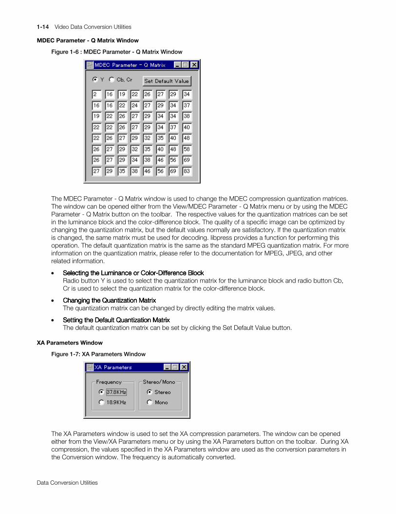
MDEC Parameter - Q Matrix Window
Figure 1-6 : MDEC Parameter - Q Matrix Window
The MDEC Parameter - Q Matrix window is used to change the MDEC compression quantization matrices.The window can be opened either from the View/MDEC Parameter - Q Matrix menu or by using the MDECParameter - Q Matrix button on the toolbar. The respective values for the quantization matrices can be setin the luminance block and the color-difference block. The quality of a specific image can be optimized bychanging the quantization matrix, but the default values normally are satisfactory. If the quantization matrixis changed, the same matrix must be used for decoding. libpress provides a function for performing thisoperation. The default quantization matrix is the same as the standard MPEG quantization matrix. For moreinformation on the quantization matrix, please refer to the documentation for MPEG, JPEG, and otherrelated information.
x Selecting the Luminance or Color-Difference BlockSelecting the Luminance or Color-Difference BlockSelecting the Luminance or Color-Difference BlockSelecting the Luminance or Color-Difference BlockRadio button Y is used to select the quantization matrix for the luminance block and radio button Cb,Cr is used to select the quantization matrix for the color-difference block.
x Changing the Quantization MatrixChanging the Quantization MatrixChanging the Quantization MatrixChanging the Quantization MatrixThe quantization matrix can be changed by directly editing the matrix values.
x Setting the Default Quantization MatrixSetting the Default Quantization MatrixSetting the Default Quantization MatrixSetting the Default Quantization MatrixThe default quantization matrix can be set by clicking the Set Default Value button.
XA Parameters Window
Figure 1-7: XA Parameters Window
The XA Parameters window is used to set the XA compression parameters. The window can be openedeither from the View/XA Parameters menu or by using the XA Parameters button on the toolbar. During XAcompression, the values specified in the XA Parameters window are used as the conversion parameters inthe Conversion window. The frequency is automatically converted.

Video Data Conversion Utilities 1-15
Printed:11/19/98 4:16 PM By:SCEA Filename:final44Dataconv.doc Last saved by:SONY On:11/19/98 3:28 PM Comments: Master Copy, TechRef Release 4.3.
Data Conversion Utilities
x Selecting the FrequencySelecting the FrequencySelecting the FrequencySelecting the FrequencyThe sampling frequency for XA data can be selected using the radio buttons in the Frequency group.
x Selecting Stereo or MonauralSelecting Stereo or MonauralSelecting Stereo or MonauralSelecting Stereo or MonauralStereo or monaural mode can be selected using the radio buttons in the Stereo/Mono group.
Script Window
Figure 1-8: Script Window
The Script window is used to initiate batch conversions from a script file. The Script window can be openedfrom either the File/New menu or the File/Open menu. If the Script window is opened from the File/Newmenu, an empty script will be displayed. If the Script window is opened from the File/Open menu, the scriptwhich is opened will be displayed.
x Editing a ScriptEditing a ScriptEditing a ScriptEditing a ScriptA script which is displayed can be edited directly. Standard editing operations (i.e., Copy, Paste, Cut,Undo) can be performed either from the Edit menu, by using the corresponding buttons on the toolbar,or through shortcuts. Large scripts cannot be edited in the Script window. A text editor should be usedto edit a large script outside of mc32.
x Running a ScriptRunning a ScriptRunning a ScriptRunning a ScriptA script can be started by clicking the Go button. Progress is displayed by a gauge during execution.The script can be cancelled by clicking the Cancel button.

1-16 Video Data Conversion Utilities
Printed:11/19/98 4:16 PM By:SCEA Filename:final44Dataconv.doc Last saved by:SONY On:11/19/98 3:28 PM Comments: Master Copy, TechRef Release 4.3.
Data Conversion Utilities
Video Window
Figure 1-9: Video Window
The Video window is used to verify an input image or to check the quality of an MDEC-compressed imageon the PC. The Video window can be opened from the File/Open menu or by using the input referencebutton in the Conversion window, after reading a video or still-image file. Because the colorimetry of a PCmonitor may be different from the colorimetry of the monitor attached to the PlayStation, the final imagequality should be verified using actual equipment.
x Playing a VideoPlaying a VideoPlaying a VideoPlaying a VideoA video can be played back from the current frame to the last frame by pressing the Play button. Thedesired playback speed is set by the Video Play Back Frame Rate in the General Setting dialog box.Note that the actual playback speed will depend on the current PC load and whether or not othervideos are being simultaneously played back. If processing is too slow, the frame rate should bereduced to avoid dropping frames. While a video is playing, the Play button, which will appear as theStop button, can be used to terminate playback. The quality of a compressed image can be roughlydetermined by playing back the STR(MDEC) data.
x Displaying an Arbitrary FrameDisplaying an Arbitrary FrameDisplaying an Arbitrary FrameDisplaying an Arbitrary FrameA frame can be displayed by directly entering its frame number or by operating the slider.
x Checking the Image Quality after MDECChecking the Image Quality after MDECChecking the Image Quality after MDECChecking the Image Quality after MDEC Compression Compression Compression CompressionThe quality of an image after MDEC compression can be checked by clicking the Encode button. Thiswill display the result of compressing/expanding the currently displayed frame. Compression iscontrolled by the compression parameter values in the MDEC Parameters window and the MDECParameters - Q Matrix window.
Video Data Conversion Utilities 1-17
Printed:11/19/98 4:16 PM By:SCEA Filename:final44Dataconv.doc Last saved by:SONY On:11/19/98 3:28 PM Comments: Master Copy, TechRef Release 4.3.
Data Conversion Utilities
Sound Window
Figure 1-10: Sound Window
The Sound window displays the frequency and stereo/monaural settings of the input file. It does not acceptany input data. The Sound window can be opened from the File/Open menu or by using the input referencebutton in the Conversion window after a sound file is read.
General Setting Dialog Box
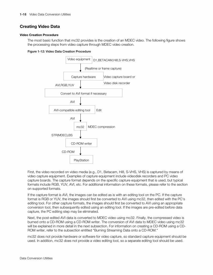
Figure 1-11: General Setting Dialog Box
The General Setting dialog box is used for making general-purpose settings in mc32. The General Settingdialog box is opened from the Setting/General Setting menu.
x Setting the Script Log FilenameSetting the Script Log FilenameSetting the Script Log FilenameSetting the Script Log FilenameDuring execution of a script, warning messages normally appear in a dialog box. These messages canbe written to an output file by checking the Script Log File check box and specifying the log filename.The log file is particularly useful when performing a large number of conversions using a script.
x Setting the Video Playback Frame RateSetting the Video Playback Frame RateSetting the Video Playback Frame RateSetting the Video Playback Frame RateThe frame rate of video playback can be set in the Video Play Back Frame Rate input field in theGeneral Setting dialog box. Note that the actual playback speed will depend on the current PC loadand whether or not other videos are being simultaneously played back. If processing is too slow, theframe rate should be reduced to avoid dropping frames.
Data Conversion without Using a GUI
mc32 can perform its processing without displaying a window.
Use the command:
> mc32 -s script_file
to execute mc32 on the DOS command line window without a GUI.
The argument "script_file" indicates the specified script. Using a script file allows mc32 to be invoked froma batch file or other external script.
1-18 Video Data Conversion Utilities
Printed:11/19/98 4:16 PM By:SCEA Filename:final44Dataconv.doc Last saved by:SONY On:11/19/98 3:28 PM Comments: Master Copy, TechRef Release 4.3.
Data Conversion Utilities
Creating Video Data
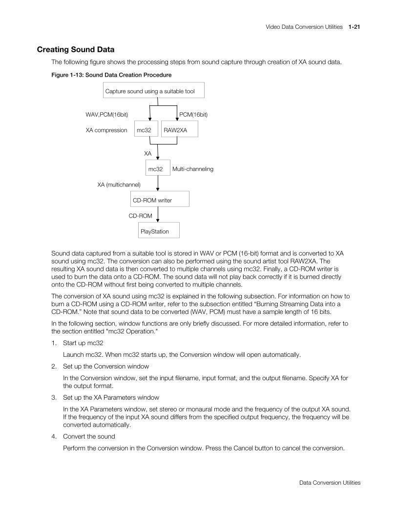
Video Creation Procedure
The most basic function that mc32 provides is the creation of an MDEC video. The following figure showsthe processing steps from video capture through MDEC video creation.
Figure 1-12: Video Data Creation Procedure
Video equipment
CD-ROM writer
mc32
AVI-compatible editing tool
Convert to AVI format if necessary
D1,BETACAM,Hi8,S-VHS,VHS
PlayStation
Capture hardware Video capture board or
Video disk recorder
STR(MDEC),BS
AVI,RGB,YUV
CD-ROM
AVI
(Realtime or frame capture)
AVI
Edit
MDEC compression
First, the video recorded on video media (e.g., D1, Betacam, Hi8, S-VHS, VHS) is captured by means ofvideo capture equipment. Examples of capture equipment include videodisk recorders and PC videocapture boards. The capture format depends on the specific capture equipment that is used, but typicalformats include RGB, YUV, AVI, etc. For additional information on these formats, please refer to the sectionon supported formats.
If the capture format is AVI, the images can be edited as is with an editing tool on the PC. If the captureformat is RGB or YUV, the images should first be converted to AVI using mc32, then edited with the PC'sediting tool. For other capture formats, the images should first be converted to AVI using an appropriateconversion tool, then subsequently edited using an editing tool. If the images are pre-edited before datacapture, the PC editing step may be eliminated.
Next, the post-edited AVI data is converted to MDEC video using mc32. Finally, the compressed video isburned onto a CD-ROM using a CD-ROM writer. The conversion of AVI data to MDEC video using mc32will be explained in more detail in the next subsection. For information on creating a CD-ROM using a CD-ROM writer, refer to the subsection entitled "Burning Streaming Data onto a CD-ROM."
mc32 does not provide hardware or software for video capture, so standard capture equipment should beused. In addition, mc32 does not provide a video editing tool, so a separate editing tool should be used.

Video Data Conversion Utilities 1-19
Printed:11/19/98 4:16 PM By:SCEA Filename:final44Dataconv.doc Last saved by:SONY On:11/19/98 3:28 PM Comments: Master Copy, TechRef Release 4.3.
Data Conversion Utilities
In the following section, window functions are only briefly discussed. For more detailed information, refer tothe section entitled “mc32 Operation.”
Creating Video Data Without Sound
MDEC video is broadly divided into two types: video without sound and video with sound. MDEC videouses the sector image of the CD-ROM as its basic format. However, sector size will vary depending onwhether the data type is video with sound or video without sound. For video with sound, 1 sector = 2336bytes, and image data is interleaved with sound data at a fixed rate. For video without sound, 1 sector =2048 bytes. Thus the internal structure varies depending on which data type is used. Consequently, it isimportant to know whether the data type is with or without sound (or is only sound data) for conversion andwhen burning data onto the CD-ROM. Please refer to the STR data document for details regarding therespective data formats.
The following procedure is used to create video data without sound:
1. Prepare for conversion
Prepare the video data to be converted. The pre-conversion data may include sound. Subsequentsettings can be used to convert only the image component. mc32 does not convert the image size orthe frame rate, therefore, it is necessary to convert these attributes separately before inputting the datainto mc32. This conversion can be performed using a general editing tool. As required, the images canalso be filtered using a tool such as a low-pass filter in order to maintain high image quality aftercompression.
2. Start up mc32
Launch mc32. When mc32 starts up, the Conversion window will open automatically.
3. Set up the Conversion window
In the Conversion window, set the input filename, input format, and the output filename. SpecifySTR(MDEC) for the output format.
4. Set up the MDEC Parameters window
Clear the Sound check box in the Output Type so that the output data will be without sound. Thischeck box is only for specifying the output type, regardless of whether the input data does or does nothave sound. Even if the input data contains sound, the sound will not be converted if the Sound checkbox has been cleared. The MDEC Image Version should normally be specified as version 2.
If Easy Settings is selected, the frame rate, number of channels, CD-ROM playback speed, and leapsector can be set. For the frame rate, specify the frame rate during playback. Even if the frame rate ofthe input image is different from the specified frame rate, the conversion will still be performed.However, during playback, slow playback or speed playback will be indicated. Therefore, the framerate of the input image should be converted separately to the playback frame rate.
Specify 1 ch for the number of channels. The playback speed of the CD-ROM will set the playbacktime value. Set or clear the leap sector depending upon whether the input images are materialcaptured from an image medium or were created by means of CG rendering. For further information,refer to the "MDEC Parameters Window" subsection.
If Custom Settings is selected, set the maximum frame size and the frame integration method.
5. Set up the MDEC Parameter - Q Matrix window
The MDEC Parameter - Q Matrix window can be used to update a value in the quantization matrix.Normally, this is not necessary.
6. Check image quality check in the Video window
After the filename is specified using the File Input dialog box in the Conversion window, the Videowindow will be opened automatically. The Video window can also be opened by specifying the input filein the File/Open menu. Use the Encode button in the Video window to compress/expand the displayed

1-20 Video Data Conversion Utilities
Printed:11/19/98 4:16 PM By:SCEA Filename:final44Dataconv.doc Last saved by:SONY On:11/19/98 3:28 PM Comments: Master Copy, TechRef Release 4.3.
Data Conversion Utilities
image and check the image quality. If there is a problem with the image quality, make adjustments inthe MDEC Parameters window and recheck the image.
7. Convert
If the image quality is acceptable, perform the conversion in the Conversion window. Press the Cancelbutton to cancel the conversion.
Creating Video Data with Sound (Simultaneous Conversion of Sound)
There are two ways to create video data with sound. One method involves converting AVI with sound tovideo with sound, simultaneously converting the video and sound components. The other method convertsthe video and sound components separately, then mixes them together after conversion.
In order to simultaneously convert video and sound, the input data must include sound. The processingsteps are almost identical to the procedure for creating video data without sound, except that the Soundcheck box must be checked in the Output Type setting of the MDEC Parameters window. Note that whenthe input video contains sound and this check box is set, sound conversion and video/sound synthesis areperformed automatically after the video is converted.
Creating Video Data with Sound (Separate Conversion of Sound)
When the input video data does not contain sound, it is necessary to perform video conversion, soundconversion, and synthesis separately.
1. Create the Video Data
The procedure for creating video data is almost identical to that for creating video data without sound.The only difference is that the Sound check box must be checked in the Output Type setting of theMDEC Parameters window.
When the input video does not contain sound and this check box is set, the video is compressed afterdeducting the size of the sound component. This assumes that the video will ultimately be combinedwith the sound. Because the input video does not contain sound, care must be taken to avoidaccidentally clearing the Sound check box. The Sound check box is used to specify sound / no soundfor the final output video, therefore, if the Sound check box is cleared by mistake, conversion will beperformed and the video will be synthesized with the sound, but the final video and sound will not besynchronized.
2. Create the Sound Data
The sound data creation procedure is exactly the same as the procedure for creating sound data thatis described in the next section. The sound artist tool (RAW2XA) can be used for sound conversioninstead of mc32ï
3. Synthesize the Video with the Sound
Synthesis can be performed after entering the required items (e.g., input video, input sound, outputfilename, conversion parameters, etc.) in the Video+Sound window.
Video Data Conversion Utilities 1-21
Printed:11/19/98 4:16 PM By:SCEA Filename:final44Dataconv.doc Last saved by:SONY On:11/19/98 3:28 PM Comments: Master Copy, TechRef Release 4.3.
Data Conversion Utilities
Creating Sound Data
The following figure shows the processing steps from sound capture through creation of XA sound data.
Figure 1-13: Sound Data Creation Procedure
RAW2XA
mc32
CD-ROM writer
PlayStation
Capture sound using a suitable tool
mc32
CD-ROM
WAV,PCM(16bit)
XA
XA (multichannel)
PCM(16bit)
Multi-channeling
XA compression
Sound data captured from a suitable tool is stored in WAV or PCM (16-bit) format and is converted to XAsound using mc32. The conversion can also be performed using the sound artist tool RAW2XA. Theresulting XA sound data is then converted to multiple channels using mc32. Finally, a CD-ROM writer isused to burn the data onto a CD-ROM. The sound data will not play back correctly if it is burned directlyonto the CD-ROM without first being converted to multiple channels.
The conversion of XA sound using mc32 is explained in the following subsection. For information on how toburn a CD-ROM using a CD-ROM writer, refer to the subsection entitled “Burning Streaming Data into aCD-ROM.” Note that sound data to be converted (WAV, PCM) must have a sample length of 16 bits.
In the following section, window functions are only briefly discussed. For more detailed information, refer tothe section entitled "mc32 Operation."
1. Start up mc32
Launch mc32. When mc32 starts up, the Conversion window will open automatically.
2. Set up the Conversion window
In the Conversion window, set the input filename, input format, and the output filename. Specify XA forthe output format.
3. Set up the XA Parameters window
In the XA Parameters window, set stereo or monaural mode and the frequency of the output XA sound.If the frequency of the input XA sound differs from the specified output frequency, the frequency will beconverted automatically.
4. Convert the sound
Perform the conversion in the Conversion window. Press the Cancel button to cancel the conversion.

1-22 Video Data Conversion Utilities
Printed:11/19/98 4:16 PM By:SCEA Filename:final44Dataconv.doc Last saved by:SONY On:11/19/98 3:28 PM Comments: Master Copy, TechRef Release 4.3.
Data Conversion Utilities
5. Set up the Multi Channel window
Follow the procedure described in the "Multi Channel Window" subsection to create multiple channelsof XA sound. Since XA sound is a subheader file format with 2336-bytes/sector, check the Sub Headercheck box for both input and output.
Creating Multichannel Data
Multichannel Streaming
Multichannel streaming is a streaming format used to interleave multiple streams of data on a CD-ROM. Inordinary streaming, one stream of data occupies contiguous regions on the CD-ROM. In multichannelstreaming, however, multiple channels are interleaved in contiguous regions on the CD-ROM. Each channelis given a channel number, so it is possible to play only a specific channel during playback.
Figure 1-14: Ordinary Streaming
Data a
CD-ROM a
Figure 1-15: Multi-channel Streaming
Data d
Data c
Data b
Data a
CD-ROM
Channel
Multi-channeling (interleaved)
Channel 3
Channel 2
Channel 1
Channel 0
a d b c a d b c a d b c a d b c
a
d
b
c
a
d
b
c
a
d
b
c
a
d
b
c
0 3 1 2 0 3 1 2 0 3 1 2 0 3 1 2
Multichannel streaming has some important advantages: CD-ROM storage can be used efficiently, andplayback data can be switched at high speed.
Efficient Use of CD-ROM Storage
In ordinary streaming (without multiple channels), the amount of CD-ROM storage needed depends only onthe playback time of the streaming data. In other words, for a given playback time, all streaming datarequire exactly the same amount of storage on the CD-ROM. For example, for a 16x16-size video and a640x240-size video, if playback time is the same for both, the amount of CD-ROM storage required willalso be the same. This is because the PlayStation's streaming mechanism operates in sync with thereading of data from the CD-ROM.
However, if the storage areas on the CD-ROM are examined more closely, it is evident that not all of theseareas are used efficiently. For example, for a 16x16-size video, large spaces are inserted between eachframe's data in order to correctly maintain playback timing. Generally speaking, if frame data is sparse, thespaces are large. If there is a lot of frame data, the spaces are small. In the case of 16x16-size video, theframe data is so sparse that the spaces themselves become much larger than the actual data. In
Video Data Conversion Utilities 1-23
Printed:11/19/98 4:16 PM By:SCEA Filename:final44Dataconv.doc Last saved by:SONY On:11/19/98 3:28 PM Comments: Master Copy, TechRef Release 4.3.
Data Conversion Utilities
multichannel streaming, this space contains other streaming data. Consequently, multichannel streamingcan use CD-ROM storage more efficiently than ordinary streaming.
Figure 1-16: Efficient use of CD-ROM storage with multiple channels
a b b b b b b b b a a a a a a a
b b b b b b b b
a a a a a a a a
Multi-channeling (interleaved)
Frame data is small
Frame data is large
1 frame
space
a a a a a a a a
1 frame
High-Speed Switching of Playback Data
In multichannel streaming, it is possible to switch to other streaming data by merely changing the specifiedchannel to be played back. Because a CD-ROM head seek is not required, switching is very fast. Switchingcan also be performed during playback.
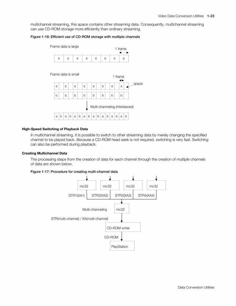
Creating Multichannel Data
The processing steps from the creation of data for each channel through the creation of multiple channelsof data are shown below.
Figure 1-17: Procedure for creating multi-channel data
mc32
CD-ROM writer
PlayStation
mc32
CD-ROM
STR(multi-channel) / XA(multi-channel)
mc32 mc32 mc32
STR1(XA1) STR2(XA2) STR3(XA3) STR4(XA4)
Multi-channeling

1-24 Video Data Conversion Utilities
Printed:11/19/98 4:16 PM By:SCEA Filename:final44Dataconv.doc Last saved by:SONY On:11/19/98 3:28 PM Comments: Master Copy, TechRef Release 4.3.
Data Conversion Utilities
1. Start up mc32
Launch mc32. When mc32 starts up, the Conversion window will open automatically.
2. Create data for each channel using the Conversion window
Multiple channels of MDEC video and XA sound can be created in mc32. This is done by creatingmultiple channels in advance, then converting the data into the appropriate bands.
For example, in order to perform four channels of multichannel streaming during double-speedplayback, the band allowed per channel is calculated as follows:
300(KByte/sec) / 4 = 75(KBytes/sec)
(double-speed CD-ROM data transfer rate: 300 Kbytes/sec)
For MDEC video, the desired values for the total number of channels for conversion should be set inthe MDEC Parameters window. For XA audio, the total number of channels is determined automaticallyaccording to the CD-ROM speed, frequency, and whether the mode is stereo or monaural, so it doesnot need to be specified. For more information on the conversion of video and sound, please refer tothe sections entitled "Creation of Video" and "Creation of Sound," respectively.
3. Set up the Multi Channel window
The total number of channels specified in the Multi Channel window depends on the type of data to beprocessed. For MDEC video, use the total number of channels that were specified during channel datacreation. For XA sound, use the total number of channels as described in the subsection entitled "MultiChannel Window."
4. Create multiple channels
Perform the conversion in the Multi Channel window. Press the Cancel button to cancel theconversion.
Scripting
mc32 has a function which allows conversions to be performed in batch mode. A script file describes thebatch processing flow. Script files allows large numbers of conversions to be performed in a singleoperation. For more information on script editing and execution, please refer to the "Script Window"subsection.
The syntax of an mc32 script is very simple. Functions are executed sequentially, and there is no branchingor looping. The functions that can be used within a script perform interleaving and conversion operations.
The following list contains all scripting functions available in mc32. The function names and their argumentsare not case sensitive. Functions that end with AV are used to perform video/sound synthesis after videoconversion. Functions that end in V are used when synthesis is not to be performed after video conversion.Functions that end in C are used when the frame size is specified directly. For example, when the input isAVI with sound, Avi2strMdecAV() converts AVI video to STR(MDEC), automatically converts the sound, thenautomatically synthesizes the video together with the sound.
If a line begins with a # symbol it is considered to be a comment.

Video Data Conversion Utilities 1-25
Printed:11/19/98 4:16 PM By:SCEA Filename:final44Dataconv.doc Last saved by:SONY On:11/19/98 3:28 PM Comments: Master Copy, TechRef Release 4.3.
Data Conversion Utilities
Table 1-6: Script Functions
Function Description
Avi2strMdecAv() Creates STR(MDEC) from AVI (Easy Settings).
Avi2strMdecV() Creates STR(MDEC) from AVI (Easy Settings).
Avi2strMdecC() Creates STR(MDEC) from AVI (Custom Settings).
Avi2bsAv() Creates BS from AVI (Easy Settings).
Avi2bsV() Creates BS from AVI (Easy Settings).
Avi2bsC() Creates BS from AVI (Custom Settings).
Yuv2strMdecAv() Creates STR(MDEC) from YUV (Easy Settings).
Yuv2strMdecV() Creates STR(MDEC) from YUV (Easy Settings).
Yuv2strMdecC() Creates STR(MDEC) from YUV (Custom Settings).
Yuv2bsAv Creates BS from YUV (Easy Settings).
Yuv2bsV Creates BS from YUV (Easy Settings).
Yuv2bsC Creates BS from YUV (Custom Settings).
Yuv2Avi Creates AVI from YUV.
Rgb2strMdecAv() Creates STR(MDEC) from RGB (Easy Settings).
Rgb2strMdecV() Creates STR(MDEC) from RGB (Easy Settings).
Rgb2strMdecC() Creates STR(MDEC) from RGB (Custom Settings).
Rgb2bsAv Creates BS from RGB (Easy Settings).
Rgb2bsV Creates BS from RGB (Easy Settings).
Rgb2bsC Creates BS from RGB (Custom Settings).
Rgb2Avi Creates AVI from RGB.
Tim2strMdecAv Creates STR(MDEC) from TIM (Easy Settings).
Tim2strMdecV Creates STR(MDEC) from TIM (Easy Settings).
Tim2strMdecC Creates STR(MDEC) from TIM (Custom Settings).
Tim2bsAv Creates BS from TIM (Easy Settings).
Tim2bsV Creates BS from TIM (Easy Settings).
Tim2bsC Creates BS from TIM (Custom Settings).
Wav2xa() Creates XA from a WAV file.
Pcm2xa() Creates XA from a PCM file.
MakeAv() Synthesizes video with sound.
MakeV() Converts the video format.
Pack1ch Performs multichanneling (1 ch).
Pack2ch Performs multichanneling (2 ch).
Pack4xh Performs multichanneling (4 ch).
Pack8ch Performs multichanneling (8 ch).
Pack16ch Performs multichanneling (16 ch).
Pack32ch Performs multichanneling (32 ch).
SetQ Sets the quantization matrices.
SetDefaultQ Sets the default values in the quantization matrices.
1-26 Video Data Conversion Utilities
Printed:11/19/98 4:16 PM By:SCEA Filename:final44Dataconv.doc Last saved by:SONY On:11/19/98 3:28 PM Comments: Master Copy, TechRef Release 4.3.
Data Conversion Utilities
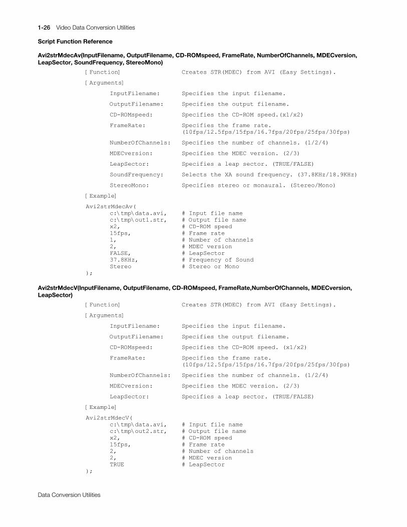
Script Function Reference
Avi2strMdecAv(InputFilename, OutputFilename, CD-ROMspeed, FrameRate, NumberOfChannels, MDECversion,LeapSector, SoundFrequency, StereoMono)
>)XQFWLRQ@ &UHDWHV#675+0'(&,#IURP#$9,#+(DV\#6HWWLQJV,1
>$UJXPHQWV@
,QSXW)LOHQDPH=# 6SHFLILHV#WKH#LQSXW#ILOHQDPH1
2XWSXW)LOHQDPH= 6SHFLILHV#WKH#RXWSXW#ILOHQDPH1
&'0520VSHHG= 6SHFLILHV#WKH#&'0520#VSHHG1+[42[5,
)UDPH5DWH= 6SHFLILHV#WKH#IUDPH#UDWH1+43ISV24518ISV248ISV2491:ISV253ISV258ISV263ISV,
1XPEHU2I&KDQQHOV= 6SHFLILHV#WKH#QXPEHU#RI#FKDQQHOV1#+42527,
0'(&YHUVLRQ= 6SHFLILHV#WKH#0'(&#YHUVLRQ1#+526,
/HDS6HFWRU= 6SHFLILHV#D#OHDS#VHFWRU1#+758(2)$/6(,
6RXQG)UHTXHQF\= 6HOHFWV#WKH#;$#VRXQG#IUHTXHQF\1#+6:1;.+]24;1<.+],
6WHUHR0RQR= 6SHFLILHV#VWHUHR#RU#PRQDXUDO1#+6WHUHR20RQR,
>([DPSOH@
$YL5VWU0GHF$Y+F=?WPS?GDWD1DYL/ &#,QSXW#ILOH#QDPHF=?WPS?RXW41VWU/ XWSXW#ILOH#QDPH[5/ &#&'0520#VSHHG48ISV/ &#)UDPH#UDWH4/ XPEHU#RI#FKDQQHOV5/ �'(&#YHUVLRQ)$/6(/ &#/HDS6HFWRU6:1;.+]/ &#)UHTXHQF\#RI#6RXQG6WHUHR WHUHR#RU#0RQR
,>
Avi2strMdecV(InputFilename, OutputFilename, CD-ROMspeed, FrameRate,NumberOfChannels, MDECversion,LeapSector)
>)XQFWLRQ@ &UHDWHV#675+0'(&,#IURP#$9,#+(DV\#6HWWLQJV,1
>$UJXPHQWV@
,QSXW)LOHQDPH=# 6SHFLILHV#WKH#LQSXW#ILOHQDPH1
2XWSXW)LOHQDPH= 6SHFLILHV#WKH#RXWSXW#ILOHQDPH1
&'0520VSHHG= 6SHFLILHV#WKH#&'0520#VSHHG1#+[42[5,
)UDPH5DWH= 6SHFLILHV#WKH#IUDPH#UDWH1+43ISV24518ISV248ISV2491:ISV253ISV258ISV263ISV,
1XPEHU2I&KDQQHOV= 6SHFLILHV#WKH#QXPEHU#RI#FKDQQHOV1#+42527,
0'(&YHUVLRQ= 6SHFLILHV#WKH#0'(&#YHUVLRQ1#+526,
/HDS6HFWRU= 6SHFLILHV#D#OHDS#VHFWRU1#+758(2)$/6(,
>([DPSOH@
$YL5VWU0GHF9+F=?WPS?GDWD1DYL/ &#,QSXW#ILOH#QDPHF=?WPS?RXW51VWU/ XWSXW#ILOH#QDPH[5/ &#&'0520#VSHHG48ISV/ &#)UDPH#UDWH5/ XPEHU#RI#FKDQQHOV5/ �'(&#YHUVLRQ758( &#/HDS6HFWRU
,>
Video Data Conversion Utilities 1-27
Printed:11/19/98 4:16 PM By:SCEA Filename:final44Dataconv.doc Last saved by:SONY On:11/19/98 3:28 PM Comments: Master Copy, TechRef Release 4.3.
Data Conversion Utilities
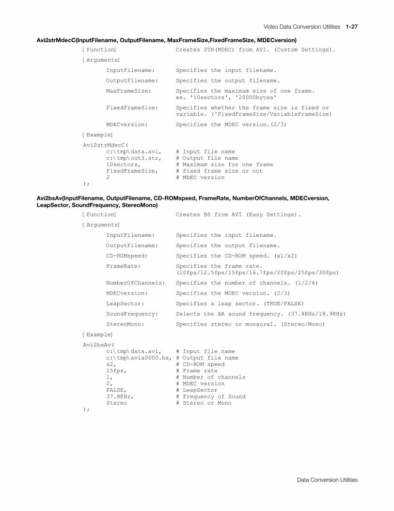
Avi2strMdecC(InputFilename, OutputFilename, MaxFrameSize,FixedFrameSize, MDECversion)
>)XQFWLRQ@ &UHDWHV#675+0'(&,#IURP#$9,1#+&XVWRP#6HWWLQJV,1
>$UJXPHQWV@
,QSXW)LOHQDPH=# 6SHFLILHV#WKH#LQSXW#ILOHQDPH1
2XWSXW)LOHQDPH= 6SHFLILHV#WKH#RXWSXW#ILOHQDPH1
0D[)UDPH6L]H= 6SHFLILHV#WKH#PD[LPXP#VL]H#RI#RQH#IUDPH1H[1#*43VHFWRUV*/#*53333E\WHV*
)L[HG)UDPH6L]H= 6SHFLILHV#ZKHWKHU#WKH#IUDPH#VL]H#LV#IL[HG#RUYDULDEOH1#+*)L[HG)UDPH6L]H29DULDEOH)UDPH6L]H,
0'(&YHUVLRQ= 6SHFLILHV#WKH#0'(&#YHUVLRQ1+526,
>([DPSOH@
$YL5VWU0GHF&+F=?WPS?GDWD1DYL/ &#,QSXW#ILOH#QDPHF=?WPS?RXW61VWU/ XWSXW#ILOH#QDPH43VHFWRUV/ �D[LPXP#VL]H#IRU#RQH#IUDPH)L[HG)UDPH6L]H/ &#)L[HG#IUDPH#VL]H#RU#QRW5 �'(&#YHUVLRQ
,>
Avi2bsAv(InputFilename, OutputFilename, CD-ROMspeed, FrameRate, NumberOfChannels, MDECversion,LeapSector, SoundFrequency, StereoMono)
>)XQFWLRQ@ &UHDWHV#%6#IURP#$9,#+(DV\#6HWWLQJV,1
>$UJXPHQWV@
,QSXW)LOHQDPH=# 6SHFLILHV#WKH#LQSXW#ILOHQDPH1
2XWSXW)LOHQDPH= 6SHFLILHV#WKH#RXWSXW#ILOHQDPH1
&'0520VSHHG= 6SHFLILHV#WKH#&'0520#VSHHG1#+[42[5,
)UDPH5DWH= 6SHFLILHV#WKH#IUDPH#UDWH1+43ISV24518ISV248ISV2491:ISV253ISV258ISV263ISV,
1XPEHU2I&KDQQHOV= 6SHFLILHV#WKH#QXPEHU#RI#FKDQQHOV1#+42527,
0'(&YHUVLRQ= 6SHFLILHV#WKH#0'(&#YHUVLRQ1#+526,
/HDS6HFWRU= 6SHFLILHV#D#OHDS#VHFWRU1#+758(2)$/6(,
6RXQG)UHTXHQF\= 6HOHFWV#WKH#;$#VRXQG#IUHTXHQF\1#+6:1;.+]24;1<.+],
6WHUHR0RQR= 6SHFLILHV#VWHUHR#RU#PRQDXUDO1#+6WHUHR20RQR,
>([DPSOH@
$YL5EV$Y+F=?WPS?GDWD1DYL/ &#,QSXW#ILOH#QDPHF=?WPS?DYLD33331EV/ XWSXW#ILOH#QDPH[5/ &#&'0520#VSHHG48ISV/ &#)UDPH#UDWH4/ XPEHU#RI#FKDQQHOV5/ �'(&#YHUVLRQ)$/6(/ &#/HDS6HFWRU6:1;.+]/ &#)UHTXHQF\#RI#6RXQG6WHUHR WHUHR#RU#0RQR
,>

1-28 Video Data Conversion Utilities
Printed:11/19/98 4:16 PM By:SCEA Filename:final44Dataconv.doc Last saved by:SONY On:11/19/98 3:28 PM Comments: Master Copy, TechRef Release 4.3.
Data Conversion Utilities
Avi2bsV(InputFilename, OutputFilename, CD-ROMspeed, FrameRate,NumberOfChannels, MDECversion,LeapSector)
>)XQFWLRQ@ &UHDWHV#%6#IURP#$9,#+(DV\#6HWWLQJV,1
>$UJXPHQWV@
,QSXW)LOHQDPH=# 6SHFLILHV#WKH#LQSXW#ILOHQDPH1
2XWSXW)LOHQDPH= 6SHFLILHV#WKH#RXWSXW#ILOHQDPH1
&'0520VSHHG= 6SHFLILHV#WKH#&'0520#VSHHG1#+[42[5,
)UDPH5DWH= 6SHFLILHV#WKH#IUDPH#UDWH1+43ISV24518ISV248ISV2491:ISV253ISV258ISV263ISV,
1XPEHU2I&KDQQHOV= 6SHFLILHV#WKH#QXPEHU#RI#FKDQQHOV1#+42527,
0'(&YHUVLRQ= 6SHFLILHV#WKH#0'(&#YHUVLRQ1#+526,
/HDS6HFWRU= 6SHFLILHV#D#OHDS#VHFWRU1#+758(2)$/6(,
>([DPSOH@
$YL5EV9+F=?WPS?GDWD1DYL/ &#,QSXW#ILOH#QDPHF=?WPS?DYLY33331EV/ XWSXW#ILOH#QDPH[5/ &#&'0520#VSHHG48ISV/ &#)UDPH#UDWH5/ XPEHU#RI#FKDQQHOV5/ �'(&#YHUVLRQ758( &#/HDS6HFWRU
,>
Avi2bsC(InputFilename, OutputFilename, MaxFrameSize,FixedFrameSize, MDECversion)
>)XQFWLRQ@ &UHDWHV#%6#IURP#$9,#+&XVWRP#6HWWLQJV,1
>$UJXPHQWV@
,QSXW)LOHQDPH=# 6SHFLILHV#WKH#LQSXW#ILOHQDPH1
2XWSXW)LOHQDPH= 6SHFLILHV#WKH#RXWSXW#ILOHQDPH1
0D[)UDPH6L]H= 6SHFLILHV#WKH#PD[LPXP#VL]H#RI#RQH#IUDPH1
H[1#*43VHFWRUV*/#*53333E\WHV*
)L[HG)UDPH6L]H= 6SHFLILHV#ZKHWKHU#WKH#IUDPH#VL]H#LV#IL[HG#RUYDULDEOH1#+*)L[HG)UDPH6L]H29DULDEOH)UDPH6L]H,
0'(&YHUVLRQ= 6SHFLILHV#WKH#0'(&#YHUVLRQ1#+526,
>([DPSOH@
$YL5EV&+F=?WPS?GDWD1DYL/ &#,QSXW#ILOH#QDPHF=?WPS?DYLF33331EV/ XWSXW#ILOH#QDPH43VHFWRUV/ �D[LPXP#VL]H#IRU#RQH#IUDPH)L[HG)UDPH6L]H/ &#)L[HG#IUDPH#VL]H#RU#QRW5 �'(&#YHUVLRQ
,>
Video Data Conversion Utilities 1-29
Printed:11/19/98 4:16 PM By:SCEA Filename:final44Dataconv.doc Last saved by:SONY On:11/19/98 3:28 PM Comments: Master Copy, TechRef Release 4.3.
Data Conversion Utilities
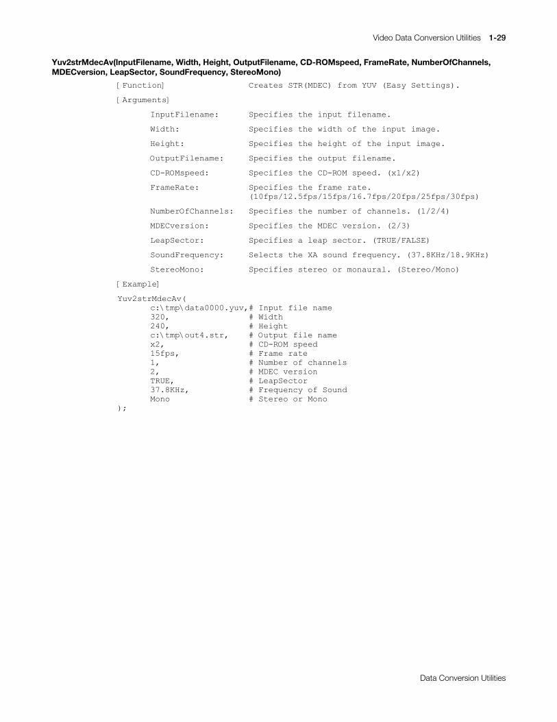
Yuv2strMdecAv(InputFilename, Width, Height, OutputFilename, CD-ROMspeed, FrameRate, NumberOfChannels,MDECversion, LeapSector, SoundFrequency, StereoMono)
>)XQFWLRQ@ &UHDWHV#675+0'(&,#IURP#<89#+(DV\#6HWWLQJV,1
>$UJXPHQWV@
,QSXW)LOHQDPH=# 6SHFLILHV#WKH#LQSXW#ILOHQDPH1
:LGWK= 6SHFLILHV#WKH#ZLGWK#RI#WKH#LQSXW#LPDJH1
+HLJKW= 6SHFLILHV#WKH#KHLJKW#RI#WKH#LQSXW#LPDJH1
2XWSXW)LOHQDPH= 6SHFLILHV#WKH#RXWSXW#ILOHQDPH1
&'0520VSHHG= 6SHFLILHV#WKH#&'0520#VSHHG1#+[42[5,
)UDPH5DWH= 6SHFLILHV#WKH#IUDPH#UDWH1+43ISV24518ISV248ISV2491:ISV253ISV258ISV263ISV,
1XPEHU2I&KDQQHOV= 6SHFLILHV#WKH#QXPEHU#RI#FKDQQHOV1#+42527,
0'(&YHUVLRQ= 6SHFLILHV#WKH#0'(&#YHUVLRQ1#+526,
/HDS6HFWRU= 6SHFLILHV#D#OHDS#VHFWRU1#+758(2)$/6(,
6RXQG)UHTXHQF\= 6HOHFWV#WKH#;$#VRXQG#IUHTXHQF\1#+6:1;.+]24;1<.+],
6WHUHR0RQR= 6SHFLILHV#VWHUHR#RU#PRQDXUDO1#+6WHUHR20RQR,
>([DPSOH@
<XY5VWU0GHF$Y+F=?WPS?GDWD33331\XY/&#,QSXW#ILOH#QDPH653/ &#:LGWK573/ &#+HLJKWF=?WPS?RXW71VWU/ XWSXW#ILOH#QDPH[5/ &#&'0520#VSHHG48ISV/ &#)UDPH#UDWH4/ XPEHU#RI#FKDQQHOV5/ �'(&#YHUVLRQ758(/ &#/HDS6HFWRU6:1;.+]/ &#)UHTXHQF\#RI#6RXQG0RQR WHUHR#RU#0RQR
,>

1-30 Video Data Conversion Utilities
Printed:11/19/98 4:16 PM By:SCEA Filename:final44Dataconv.doc Last saved by:SONY On:11/19/98 3:28 PM Comments: Master Copy, TechRef Release 4.3.
Data Conversion Utilities
Yuv2strMdecV(InputFilename, Width, Height, OutputFilename, CD-ROMspeed, FrameRate, NumberOfChannels,MDECversion, LeapSector)
>)XQFWLRQ@ &UHDWHV#675+0'(&,#IURP#<89#+(DV\#6HWWLQJV,1
>$UJXPHQWV@
,QSXW)LOHQDPH=# 6SHFLILHV#WKH#LQSXW#ILOHQDPH1
:LGWK= 6SHFLILHV#WKH#ZLGWK#RI#WKH#LQSXW#LPDJH1
+HLJKW= 6SHFLILHV#WKH#KHLJKW#RI#WKH#LQSXW#LPDJH1
2XWSXW)LOHQDPH= 6SHFLILHV#WKH#RXWSXW#ILOHQDPH1
&'0520VSHHG= 6SHFLILHV#WKH#&'0520#VSHHG1#+[42[5,
)UDPH5DWH= 6SHFLILHV#WKH#IUDPH#UDWH1+43ISV24518ISV248ISV2491:ISV253ISV258ISV263ISV,
1XPEHU2I&KDQQHOV= 6SHFLILHV#WKH#QXPEHU#RI#FKDQQHOV1#+42527,
0'(&YHUVLRQ= 6SHFLILHV#WKH#0'(&#YHUVLRQ1#+526,
/HDS6HFWRU= 6SHFLILHV#D#OHDS#VHFWRU1#+758(2)$/6(,
>([DPSOH@
<XY5VWU0GHF9+F=?WPS?GDWD33331\XY/&#,QSXW#ILOH#QDPH653/ &#:LGWK573/ &#+HLJKWF=?WPS?RXW81VWU/# XWSXW#ILOH#QDPH[5/ &#&'0520#VSHHG48ISV/ &#)UDPH#UDWH5/ XPEHU#RI#FKDQQHOV5/ �'(&#YHUVLRQ758( &#/HDS6HFWRU
,>
Yuv2strMdecC(InputFilename, Width, Height, OutputFilename, MaxFrameSize, FixedFrameSize, MDECversion)
>)XQFWLRQ@ &UHDWHV#675+0'(&,#IURP#<89#+&XVWRP#6HWWLQJV,1
>$UJXPHQWV@
,QSXW)LOHQDPH=# 6SHFLILHV#WKH#LQSXW#ILOHQDPH1
:LGWK= 6SHFLILHV#WKH#ZLGWK#RI#WKH#LQSXW#LPDJH1
+HLJKW= 6SHFLILHV#WKH#KHLJKW#RI#WKH#LQSXW#LPDJH1
2XWSXW)LOHQDPH= 6SHFLILHV#WKH#RXWSXW#ILOHQDPH1
0D[)UDPH6L]H= 6SHFLILHV#WKH#PD[LPXP#VL]H#RI#RQH#IUDPH1H[1#*43VHFWRUV*/#*53333E\WHV*
)L[HG)UDPH6L]H= 6SHFLILHV#ZKHWKHU#WKH#IUDPH#VL]H#LV#IL[HG#RUYDULDEOH1#+*)L[HG)UDPH6L]H29DULDEOH)UDPH6L]H,
0'(&YHUVLRQ= 6SHFLILHV#WKH#0'(&#YHUVLRQ1#+526,
>([DPSOH@
<XY5VWU0GHF&+F=?WPS?GDWD33331\XY/&#,QSXW#ILOH#QDPH653/ &#:LGWK573/ &#+HLJKWF=?WPS?RXW91VWU/# XWSXW#ILOH#QDPH43VHFWRUV/ �D[LPXP#VL]H#IRU#RQH#IUDPH)L[HG)UDPH6L]H/ &#)L[HG#IUDPH#VL]H#RU#QRW5 �'(&#YHUVLRQ
,>

Video Data Conversion Utilities 1-31
Printed:11/19/98 4:16 PM By:SCEA Filename:final44Dataconv.doc Last saved by:SONY On:11/19/98 3:28 PM Comments: Master Copy, TechRef Release 4.3.
Data Conversion Utilities
Yuv2bsAv (InputFilename, Width, Height, OutputFilename, CD-ROMspeed, FrameRate, NumberOfChannels,MDECversion, LeapSector, SoundFrequency, StereoMono)
>)XQFWLRQ@ &UHDWHV#%6#IURP#<89#+(DV\#6HWWLQJV,1
>$UJXPHQWV@
,QSXW)LOHQDPH=# 6SHFLILHV#WKH#LQSXW#ILOHQDPH1
:LGWK= 6SHFLILHV#WKH#ZLGWK#RI#WKH#LQSXW#LPDJH1
+HLJKW= 6SHFLILHV#WKH#KHLJKW#RI#WKH#LQSXW#LPDJH1
2XWSXW)LOHQDPH= 6SHFLILHV#WKH#RXWSXW#ILOHQDPH1
&'0520VSHHG= 6SHFLILHV#WKH#&'0520#VSHHG1#+[42[5,
)UDPH5DWH= 6SHFLILHV#WKH#IUDPH#UDWH1+43ISV24518ISV248ISV2491:ISV253ISV258ISV263ISV,
1XPEHU2I&KDQQHOV= 6SHFLILHV#WKH#QXPEHU#RI#FKDQQHOV1#+42527,
0'(&YHUVLRQ= 6SHFLILHV#WKH#0'(&#YHUVLRQ1#+526,
/HDS6HFWRU= 6SHFLILHV#D#OHDS#VHFWRU1#+758(2)$/6(,
6RXQG)UHTXHQF\= 6HOHFWV#WKH#;$#VRXQG#IUHTXHQF\1#+6:1;.+]24;1<.+],
6WHUHR0RQR= 6SHFLILHV#VWHUHR#RU#PRQDXUDO1#+6WHUHR20RQR,
>([DPSOH@
<XY5EV$Y+F=?WPS?GDWD33331\XY/&#,QSXW#ILOH#QDPH653/ &#:LGWK573/ &#+HLJKWF=?WPS?\XYD33331EV/ XWSXW#ILOH#QDPH[5/ &#&'0520#VSHHG48ISV/ &#)UDPH#UDWH4/ XPEHU#RI#FKDQQHOV5/ �'(&#YHUVLRQ758(/ &#/HDS6HFWRU6:1;.+]/ &#)UHTXHQF\#RI#6RXQG0RQR WHUHR#RU#0RQR
,>
Yuv2bsV(InputFilename, Width, Height, OutputFilename, CD-ROMspeed, FrameRate, NumberOfChannels,MDECversion, LeapSector)
>)XQFWLRQ@ &UHDWHV#%6#IURP#<89#+(DV\#6HWWLQJV,1
>$UJXPHQWV@
,QSXW)LOHQDPH=# 6SHFLILHV#WKH#LQSXW#ILOHQDPH1
:LGWK= 6SHFLILHV#WKH#ZLGWK#RI#WKH#LQSXW#LPDJH1
+HLJKW= 6SHFLILHV#WKH#KHLJKW#RI#WKH#LQSXW#LPDJH1
2XWSXW)LOHQDPH= 6SHFLILHV#WKH#RXWSXW#ILOHQDPH1
&'0520VSHHG= 6SHFLILHV#WKH#&'0520#VSHHG1#+[42[5,
)UDPH5DWH= 6SHFLILHV#WKH#IUDPH#UDWH1+43ISV24518ISV248ISV2491:ISV253ISV258ISV263ISV,
1XPEHU2I&KDQQHOV= 6SHFLILHV#WKH#QXPEHU#RI#FKDQQHOV1#+42527,
0'(&YHUVLRQ= 6SHFLILHV#WKH#0'(&#YHUVLRQ1#+526,
/HDS6HFWRU= 6SHFLILHV#D#OHDS#VHFWRU1#+758(2)$/6(,

1-32 Video Data Conversion Utilities
Printed:11/19/98 4:16 PM By:SCEA Filename:final44Dataconv.doc Last saved by:SONY On:11/19/98 3:28 PM Comments: Master Copy, TechRef Release 4.3.
Data Conversion Utilities
>([DPSOH@
<XY5EV9+F=?WPS?GDWD33331\XY/&#,QSXW#ILOH#QDPH653/ &#:LGWK573/ &#+HLJKWF=?WPS?\XYY33331EV/ XWSXW#ILOH#QDPH[5/ &#&'0520#VSHHG48ISV/ &#)UDPH#UDWH5/ XPEHU#RI#FKDQQHOV5/ �'(&#YHUVLRQ758( &#/HDS6HFWRU
,>
Yuv2bsC (InputFilename, Width, Height, OutputFilename, MaxFrameSize, FixedFrameSize, MDECversion)
>)XQFWLRQ@ &UHDWHV#%6#IURP#<89#+&XVWRP#6HWWLQJV,1
>$UJXPHQWV@
,QSXW)LOHQDPH=# 6SHFLILHV#WKH#LQSXW#ILOHQDPH1
:LGWK= 6SHFLILHV#WKH#ZLGWK#RI#WKH#LQSXW#LPDJH1
+HLJKW= 6SHFLILHV#WKH#KHLJKW#RI#WKH#LQSXW#LPDJH1
2XWSXW)LOHQDPH= 6SHFLILHV#WKH#RXWSXW#ILOHQDPH1
0D[)UDPH6L]H= 6SHFLILHV#WKH#PD[LPXP#VL]H#RI#RQH#IUDPH1H[1#*43VHFWRUV*/#*53333E\WHV*
)L[HG)UDPH6L]H= 6SHFLILHV#ZKHWKHU#WKH#IUDPH#VL]H#LV#IL[HG#RUYDULDEOH1#+*)L[HG)UDPH6L]H29DULDEOH)UDPH6L]H,
0'(&YHUVLRQ= 6SHFLILHV#WKH#0'(&#YHUVLRQ1#+526,
>([DPSOH@
<XY5EV&+F=?WPS?GDWD33331\XY/&#,QSXW#ILOH#QDPH653/ &#:LGWK573/ &#+HLJKWF=?WPS?\XYF33331EV/ XWSXW#ILOH#QDPH43VHFWRUV/ �D[LPXP#VL]H#IRU#RQH#IUDPH)L[HG)UDPH6L]H/ &#)L[HG#IUDPH#VL]H#RU#QRW5 �'(&#YHUVLRQ
,>
Yuv2Avi (InputFilename, Width, Height, OutputFilename, FrameRate)
>)XQFWLRQ@ &UHDWHV#$9,#IURP#<891
>$UJXPHQWV@
,QSXW)LOHQDPH=# 6SHFLILHV#WKH#LQSXW#ILOHQDPH1
:LGWK= 6SHFLILHV#WKH#ZLGWK#RI#WKH#LQSXW#LPDJH1
+HLJKW= 6SHFLILHV#WKH#KHLJKW#RI#WKH#LQSXW#LPDJH1
2XWSXW)LOHQDPH= 6SHFLILHV#WKH#RXWSXW#ILOHQDPH1
)UDPH5DWH= 6SHFLILHV#WKH#IUDPH#UDWH1
>([DPSOH@
<XY5DYL+F=?WPS?GDWD33331\XY/&#,QSXW#ILOH#QDPH653/ &#:LGWK573/ &#+HLJKWF=?WPS?\XY1DYL/ XWSXW#ILOH#QDPH48ISV &#)UDPH#UDWH
,>
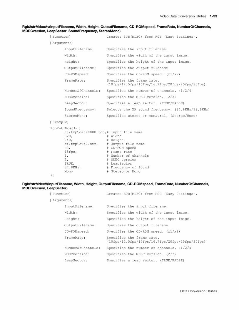
Video Data Conversion Utilities 1-33
Printed:11/19/98 4:16 PM By:SCEA Filename:final44Dataconv.doc Last saved by:SONY On:11/19/98 3:28 PM Comments: Master Copy, TechRef Release 4.3.
Data Conversion Utilities
Rgb2strMdecAv(InputFilename, Width, Height, OutputFilename, CD-ROMspeed, FrameRate, NumberOfChannels,MDECversion, LeapSector, SoundFrequency, StereoMono)
>)XQFWLRQ@ &UHDWHV#675+0'(&,#IURP#5*%#+(DV\#6HWWLQJV,1
>$UJXPHQWV@
,QSXW)LOHQDPH=# 6SHFLILHV#WKH#LQSXW#ILOHQDPH1
:LGWK= 6SHFLILHV#WKH#ZLGWK#RI#WKH#LQSXW#LPDJH1
+HLJKW= 6SHFLILHV#WKH#KHLJKW#RI#WKH#LQSXW#LPDJH1
2XWSXW)LOHQDPH= 6SHFLILHV#WKH#RXWSXW#ILOHQDPH1
&'0520VSHHG= 6SHFLILHV#WKH#&'0520#VSHHG1#+[42[5,
)UDPH5DWH= 6SHFLILHV#WKH#IUDPH#UDWH1+43ISV24518ISV248ISV2491:ISV253ISV258ISV263ISV,
1XPEHU2I&KDQQHOV= 6SHFLILHV#WKH#QXPEHU#RI#FKDQQHOV1#+42527,
0'(&YHUVLRQ= 6SHFLILHV#WKH#0'(&#YHUVLRQ1#+526,
/HDS6HFWRU= 6SHFLILHV#D#OHDS#VHFWRU1#+758(2)$/6(,
6RXQG)UHTXHQF\= 6HOHFWV#WKH#;$#VRXQG#IUHTXHQF\1#+6:1;.+]24;1<.+],
6WHUHR0RQR= 6SHFLILHV#VWHUHR#RU#PRQDXUDO1#+6WHUHR20RQR,
>([DPSOH@
5JE5VWU0GHF$Y+F=?WPS?GDWD33331UJE/&#,QSXW#ILOH#QDPH653/ &#:LGWK573/ &#+HLJKWF=?WPS?RXW:1VWU/ XWSXW#ILOH#QDPH[5/ &#&'0520#VSHHG48ISV/ &#)UDPH#UDWH4/ XPEHU#RI#FKDQQHOV5/ �'(&#YHUVLRQ758(/ &#/HDS6HFWRU6:1;.+]/ &#)UHTXHQF\#RI#6RXQG0RQR WHUHR#RU#0RQR
,>
Rgb2strMdecV(InputFilename, Width, Height, OutputFilename, CD-ROMspeed, FrameRate, NumberOfChannels,MDECversion, LeapSector)
>)XQFWLRQ@ &UHDWHV#675+0'(&,#IURP#5*%#+(DV\#6HWWLQJV,1
>$UJXPHQWV@
,QSXW)LOHQDPH=# 6SHFLILHV#WKH#LQSXW#ILOHQDPH1
:LGWK= 6SHFLILHV#WKH#ZLGWK#RI#WKH#LQSXW#LPDJH1
+HLJKW= 6SHFLILHV#WKH#KHLJKW#RI#WKH#LQSXW#LPDJH1
2XWSXW)LOHQDPH= 6SHFLILHV#WKH#RXWSXW#ILOHQDPH1
&'0520VSHHG= 6SHFLILHV#WKH#&'0520#VSHHG1#+[42[5,
)UDPH5DWH= 6SHFLILHV#WKH#IUDPH#UDWH1+43ISV24518ISV248ISV2491:ISV253ISV258ISV263ISV,
1XPEHU2I&KDQQHOV= 6SHFLILHV#WKH#QXPEHU#RI#FKDQQHOV1#+42527,
0'(&YHUVLRQ= 6SHFLILHV#WKH#0'(&#YHUVLRQ1#+526,
/HDS6HFWRU= 6SHFLILHV#D#OHDS#VHFWRU1#+758(2)$/6(,
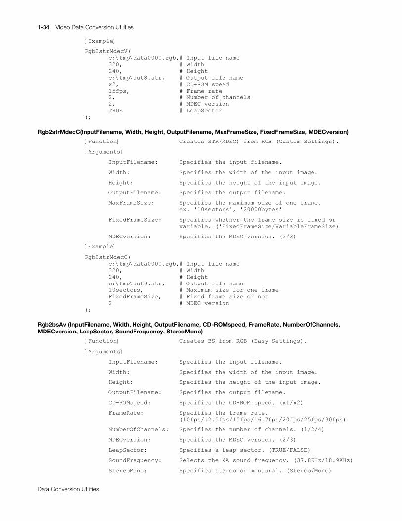
1-34 Video Data Conversion Utilities
Printed:11/19/98 4:16 PM By:SCEA Filename:final44Dataconv.doc Last saved by:SONY On:11/19/98 3:28 PM Comments: Master Copy, TechRef Release 4.3.
Data Conversion Utilities
>([DPSOH@
5JE5VWU0GHF9+F=?WPS?GDWD33331UJE/&#,QSXW#ILOH#QDPH653/ &#:LGWK573/ &#+HLJKWF=?WPS?RXW;1VWU/# XWSXW#ILOH#QDPH[5/ &#&'0520#VSHHG48ISV/ &#)UDPH#UDWH5/ XPEHU#RI#FKDQQHOV5/ �'(&#YHUVLRQ758( &#/HDS6HFWRU
,>
Rgb2strMdecC(InputFilename, Width, Height, OutputFilename, MaxFrameSize, FixedFrameSize, MDECversion)
>)XQFWLRQ@# &UHDWHV#675+0'(&,#IURP#5*%#+&XVWRP#6HWWLQJV,1
>$UJXPHQWV@
,QSXW)LOHQDPH=# 6SHFLILHV#WKH#LQSXW#ILOHQDPH1
:LGWK= 6SHFLILHV#WKH#ZLGWK#RI#WKH#LQSXW#LPDJH1
+HLJKW= 6SHFLILHV#WKH#KHLJKW#RI#WKH#LQSXW#LPDJH1
2XWSXW)LOHQDPH= 6SHFLILHV#WKH#RXWSXW#ILOHQDPH1
0D[)UDPH6L]H= 6SHFLILHV#WKH#PD[LPXP#VL]H#RI#RQH#IUDPH1H[1#*43VHFWRUV*/#*53333E\WHV*
)L[HG)UDPH6L]H= 6SHFLILHV#ZKHWKHU#WKH#IUDPH#VL]H#LV#IL[HG#RUYDULDEOH1#+*)L[HG)UDPH6L]H29DULDEOH)UDPH6L]H,
0'(&YHUVLRQ= 6SHFLILHV#WKH#0'(&#YHUVLRQ1#+526,
>([DPSOH@
5JE5VWU0GHF&+F=?WPS?GDWD33331UJE/&#,QSXW#ILOH#QDPH653/ &#:LGWK573/ &#+HLJKWF=?WPS?RXW<1VWU/# XWSXW#ILOH#QDPH43VHFWRUV/ �D[LPXP#VL]H#IRU#RQH#IUDPH)L[HG)UDPH6L]H/ &#)L[HG#IUDPH#VL]H#RU#QRW5 �'(&#YHUVLRQ
,>
Rgb2bsAv (InputFilename, Width, Height, OutputFilename, CD-ROMspeed, FrameRate, NumberOfChannels,MDECversion, LeapSector, SoundFrequency, StereoMono)
>)XQFWLRQ@ &UHDWHV#%6#IURP#5*%#+(DV\#6HWWLQJV,1
>$UJXPHQWV@
,QSXW)LOHQDPH=# 6SHFLILHV#WKH#LQSXW#ILOHQDPH1
:LGWK= 6SHFLILHV#WKH#ZLGWK#RI#WKH#LQSXW#LPDJH1
+HLJKW= 6SHFLILHV#WKH#KHLJKW#RI#WKH#LQSXW#LPDJH1
2XWSXW)LOHQDPH= 6SHFLILHV#WKH#RXWSXW#ILOHQDPH1
&'0520VSHHG= 6SHFLILHV#WKH#&'0520#VSHHG1#+[42[5,
)UDPH5DWH= 6SHFLILHV#WKH#IUDPH#UDWH1+43ISV24518ISV248ISV2491:ISV253ISV258ISV263ISV,
1XPEHU2I&KDQQHOV= 6SHFLILHV#WKH#QXPEHU#RI#FKDQQHOV1#+42527,
0'(&YHUVLRQ= 6SHFLILHV#WKH#0'(&#YHUVLRQ1#+526,
/HDS6HFWRU= 6SHFLILHV#D#OHDS#VHFWRU1#+758(2)$/6(,
6RXQG)UHTXHQF\= 6HOHFWV#WKH#;$#VRXQG#IUHTXHQF\1#+6:1;.+]24;1<.+],
6WHUHR0RQR= 6SHFLILHV#VWHUHR#RU#PRQDXUDO1#+6WHUHR20RQR,

Video Data Conversion Utilities 1-35
Printed:11/19/98 4:16 PM By:SCEA Filename:final44Dataconv.doc Last saved by:SONY On:11/19/98 3:28 PM Comments: Master Copy, TechRef Release 4.3.
Data Conversion Utilities
>([DPSOH@
5JE5EV$Y+F=?WPS?GDWD33331UJE/&#,QSXW#ILOH#QDPH653/ &#:LGWK573/ &#+HLJKWF=?WPS?UJED33331EV/ XWSXW#ILOH#QDPH[5/ &#&'0520#VSHHG48ISV/ &#)UDPH#UDWH4/ XPEHU#RI#FKDQQHOV5/ �'(&#YHUVLRQ758(/ &#/HDS6HFWRU6:1;.+]/ &#)UHTXHQF\#RI#6RXQG0RQR WHUHR#RU#0RQR
,>
Rgb2bsV(InputFilename, Width, Height, OutputFilename, CD-ROMspeed, FrameRate, NumberOfChannels,MDECversion, LeapSector)
>)XQFWLRQ@ &UHDWHV#%6#IURP#5*%#+(DV\#6HWWLQJV,1
>$UJXPHQWV@
,QSXW)LOHQDPH=# 6SHFLILHV#WKH#LQSXW#ILOHQDPH1
:LGWK= 6SHFLILHV#WKH#ZLGWK#RI#WKH#LQSXW#LPDJH1
+HLJKW= 6SHFLILHV#WKH#KHLJKW#RI#WKH#LQSXW#LPDJH1
2XWSXW)LOHQDPH= 6SHFLILHV#WKH#RXWSXW#ILOHQDPH1
&'0520VSHHG= 6SHFLILHV#WKH#&'0520#VSHHG1#+[42[5,
)UDPH5DWH= 6SHFLILHV#WKH#IUDPH#UDWH1+43ISV24518ISV248ISV2491:ISV253ISV258ISV263ISV,
1XPEHU2I&KDQQHOV= 6SHFLILHV#WKH#QXPEHU#RI#FKDQQHOV1#+42527,
0'(&YHUVLRQ= 6SHFLILHV#WKH#0'(&#YHUVLRQ1#+526,
/HDS6HFWRU= 6SHFLILHV#D#OHDS#VHFWRU1#+758(2)$/6(,
>([DPSOH@
5JE5EV9+F=?WPS?GDWD33331UJE/&#,QSXW#ILOH#QDPH653/ &#:LGWK573/ &#+HLJKWF=?WPS?UJEY33331EV/ XWSXW#ILOH#QDPH[5/ &#&'0520#VSHHG48ISV/ &#)UDPH#UDWH5/ XPEHU#RI#FKDQQHOV5/ �'(&#YHUVLRQ758( &#/HDS6HFWRU
,>

1-36 Video Data Conversion Utilities
Printed:11/19/98 4:16 PM By:SCEA Filename:final44Dataconv.doc Last saved by:SONY On:11/19/98 3:28 PM Comments: Master Copy, TechRef Release 4.3.
Data Conversion Utilities
Rgb2bsC (InputFilename, Width, Height, OutputFilename, MaxFrameSize, FixedFrameSize, MDECversion)
>)XQFWLRQ@ &UHDWHV#%6#IURP#5*%#+&XVWRP#6HWWLQJV,1
>$UJXPHQWV@
,QSXW)LOHQDPH=# 6SHFLILHV#WKH#LQSXW#ILOHQDPH1
:LGWK= 6SHFLILHV#WKH#ZLGWK#RI#WKH#LQSXW#LPDJH1
+HLJKW= 6SHFLILHV#WKH#KHLJKW#RI#WKH#LQSXW#LPDJH1
2XWSXW)LOHQDPH= 6SHFLILHV#WKH#RXWSXW#ILOHQDPH1
0D[)UDPH6L]H= 6SHFLILHV#WKH#PD[LPXP#VL]H#RI#RQH#IUDPH1H[1#*43VHFWRUV*/#*53333E\WHV*
)L[HG)UDPH6L]H= 6SHFLILHV#ZKHWKHU#WKH#IUDPH#VL]H#LV#IL[HG#RUYDULDEOH1#+*)L[HG)UDPH6L]H29DULDEOH)UDPH6L]H,
0'(&YHUVLRQ= 6SHFLILHV#WKH#0'(&#YHUVLRQ1#+526,
>([DPSOH@
5JE5EV&+F=?WPS?GDWD33331UJE/&#,QSXW#ILOH#QDPH653/ &#:LGWK573/ &#+HLJKWF=?WPS?UJEF33331EV/ XWSXW#ILOH#QDPH43VHFWRUV/ �D[LPXP#VL]H#IRU#RQH#IUDPH)L[HG)UDPH6L]H/ &#)L[HG#IUDPH#VL]H#RU#QRW5 �'(&#YHUVLRQ
,>
Rgb2Avi (InputFilename, Width, Height, OutputFilename, FrameRate)
>)XQFWLRQ@ &UHDWHV#$9,#IURP#5*%1
>$UJXPHQWV@
,QSXW)LOHQDPH=# 6SHFLILHV#WKH#LQSXW#ILOHQDPH1
:LGWK= 6SHFLILHV#WKH#ZLGWK#RI#WKH#LQSXW#LPDJH1
+HLJKW= 6SHFLILHV#WKH#KHLJKW#RI#WKH#LQSXW#LPDJH1
2XWSXW)LOHQDPH= 6SHFLILHV#WKH#RXWSXW#ILOHQDPH1
)UDPH5DWH= 6SHFLILHV#WKH#IUDPH#UDWH1
>([DPSOH@
5JE5DYL+F=?WPS?GDWD33331UJE/&#,QSXW#ILOH#QDPH653/ &#:LGWK573/ &#+HLJKWF=?WPS?UJE1DYL/ XWSXW#ILOH#QDPH48ISV &#)UDPH#UDWH
,>
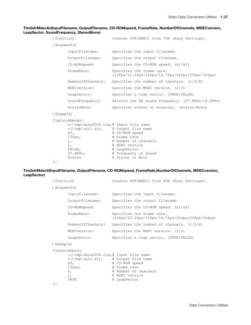
Video Data Conversion Utilities 1-37
Printed:11/19/98 4:16 PM By:SCEA Filename:final44Dataconv.doc Last saved by:SONY On:11/19/98 3:28 PM Comments: Master Copy, TechRef Release 4.3.
Data Conversion Utilities
Tim2strMdecAv(InputFilename, OutputFilename, CD-ROMspeed, FrameRate, NumberOfChannels, MDECversion,LeapSector, SoundFrequency, StereoMono)
>)XQFWLRQ@ &UHDWHV#675+0'(&,#IURP#7,0#+(DV\#6HWWLQJV,1
>$UJXPHQWV@
,QSXW)LOHQDPH=# 6SHFLILHV#WKH#LQSXW#ILOHQDPH1
2XWSXW)LOHQDPH= 6SHFLILHV#WKH#RXWSXW#ILOHQDPH1
&'0520VSHHG= 6SHFLILHV#WKH#&'0520#VSHHG1#+[42[5,
)UDPH5DWH= 6SHFLILHV#WKH#IUDPH#UDWH1+43ISV24518ISV248ISV2491:ISV253ISV258ISV263ISV,
1XPEHU2I&KDQQHOV= 6SHFLILHV#WKH#QXPEHU#RI#FKDQQHOV1#+42527,
0'(&YHUVLRQ= 6SHFLILHV#WKH#0'(&#YHUVLRQ1#+526,
/HDS6HFWRU= 6SHFLILHV#D#OHDS#VHFWRU1#+758(2)$/6(,
6RXQG)UHTXHQF\= 6HOHFWV#WKH#;$#VRXQG#IUHTXHQF\1#+6:1;.+]24;1<.+],
6WHUHR0RQR= 6SHFLILHV#VWHUHR#RU#PRQDXUDO1#+6WHUHR20RQR,
>([DPSOH@
7LP5VWU0GHF$Y+F=?WPS?GDWD33331WLP/&#,QSXW#ILOH#QDPHF=?WPS?RXW41VWU/ XWSXW#ILOH#QDPH[5/ &#&'0520#VSHHG48ISV/ &#)UDPH#UDWH4/ XPEHU#RI#FKDQQHOV5/ �'(&#YHUVLRQ)$/6(/ &#/HDS6HFWRU6:1;.+]/ &#)UHTXHQF\#RI#6RXQG6WHUHR WHUHR#RU#0RQR
,>
Tim2strMdecV(InputFilename, OutputFilename, CD-ROMspeed, FrameRate,NumberOfChannels, MDECversion,LeapSector)
>)XQFWLRQ@ &UHDWHV#675+0'(&,#IURP#7,0#+(DV\#6HWWLQJV,1
>$UJXPHQWV@
,QSXW)LOHQDPH=# 6SHFLILHV#WKH#LQSXW#ILOHQDPH1
2XWSXW)LOHQDPH= 6SHFLILHV#WKH#RXWSXW#ILOHQDPH1
&'0520VSHHG= 6SHFLILHV#WKH#&'0520#VSHHG1#+[42[5,
)UDPH5DWH= 6SHFLILHV#WKH#IUDPH#UDWH1+43ISV24518ISV248ISV2491:ISV253ISV258ISV263ISV,
1XPEHU2I&KDQQHOV= 6SHFLILHV#WKH#QXPEHU#RI#FKDQQHOV1#+42527,
0'(&YHUVLRQ= 6SHFLILHV#WKH#0'(&#YHUVLRQ1#+526,
/HDS6HFWRU= 6SHFLILHV#D#OHDS#VHFWRU1#+758(2)$/6(,
>([DPSOH@
7LP5VWU0GHF9+F=?WPS?GDWD33331WLP/&#,QSXW#ILOH#QDPHF=?WPS?RXW51VWU/ XWSXW#ILOH#QDPH[5/ &#&'0520#VSHHG48ISV/ &#)UDPH#UDWH5/ XPEHU#RI#FKDQQHOV5/ �'(&#YHUVLRQ758( &#/HDS6HFWRU
,>

1-38 Video Data Conversion Utilities
Printed:11/19/98 4:16 PM By:SCEA Filename:final44Dataconv.doc Last saved by:SONY On:11/19/98 3:28 PM Comments: Master Copy, TechRef Release 4.3.
Data Conversion Utilities
Tim2strMdecC(InputFilename, OutputFilename, MaxFrameSize,FixedFrameSize, MDECversion)
>)XQFWLRQ@ &UHDWHV#675+0'(&,#IURP#7,0#+&XVWRP#6HWWLQJV,1
>$UJXPHQWV@
,QSXW)LOHQDPH=# 6SHFLILHV#WKH#LQSXW#ILOHQDPH1
2XWSXW)LOHQDPH= 6SHFLILHV#WKH#RXWSXW#ILOHQDPH1
0D[)UDPH6L]H= 6SHFLILHV#WKH#PD[LPXP#VL]H#RI#RQH#IUDPH1H[1#*43VHFWRUV*/#*53333E\WHV*
)L[HG)UDPH6L]H= 6SHFLILHV#ZKHWKHU#WKH#IUDPH#VL]H#LV#IL[HG#RUYDULDEOH1#+*)L[HG)UDPH6L]H29DULDEOH)UDPH6L]H,
0'(&YHUVLRQ= 6SHFLILHV#WKH#0'(&#YHUVLRQ1#+526,
>([DPSOH@
7LP5VWU0GHF&+F=?WPS?GDWD33331WLP/&#,QSXW#ILOH#QDPHF=?WPS?RXW61VWU/ XWSXW#ILOH#QDPH43VHFWRUV/ �D[LPXP#VL]H#IRU#RQH#IUDPH)L[HG)UDPH6L]H/ &#)L[HG#IUDPH#VL]H#RU#QRW5 �'(&#YHUVLRQ
,>
Tim2bsAv(InputFilename, OutputFilename, CD-ROMspeed, FrameRate, NumberOfChannels, MDECversion,LeapSector, SoundFrequency, StereoMono)
>)XQFWLRQ@ &UHDWHV#%6#IURP#7,0#+(DV\#6HWWLQJV,1
>$UJXPHQWV@
,QSXW)LOHQDPH=# 6SHFLILHV#WKH#LQSXW#ILOHQDPH1
2XWSXW)LOHQDPH= 6SHFLILHV#WKH#RXWSXW#ILOHQDPH1
&'0520VSHHG= 6SHFLILHV#WKH#&'0520#VSHHG1#+[42[5,
)UDPH5DWH= 6SHFLILHV#WKH#IUDPH#UDWH1+43ISV24518ISV248ISV2491:ISV253ISV258ISV263ISV,
1XPEHU2I&KDQQHOV= 6SHFLILHV#WKH#QXPEHU#RI#FKDQQHOV1#+42527,
0'(&YHUVLRQ= 6SHFLILHV#WKH#0'(&#YHUVLRQ1#+526,
/HDS6HFWRU= 6SHFLILHV#D#OHDS#VHFWRU1#+758(2)$/6(,
6RXQG)UHTXHQF\= 6HOHFWV#WKH#;$#VRXQG#IUHTXHQF\1#+6:1;.+]24;1<.+],
6WHUHR0RQR= 6SHFLILHV#VWHUHR#RU#PRQDXUDO1#+6WHUHR20RQR,
>([DPSOH@
7LP5EV$Y+F=?WPS?GDWD33331WLP/&#,QSXW#ILOH#QDPHF=?WPS?WLPD33331EV/ XWSXW#ILOH#QDPH[5/ &#&'0520#VSHHG48ISV/ &#)UDPH#UDWH4/ XPEHU#RI#FKDQQHOV5/ �'(&#YHUVLRQ)$/6(/ &#/HDS6HFWRU6:1;.+]/ &#)UHTXHQF\#RI#6RXQG6WHUHR WHUHR#RU#0RQR
,>
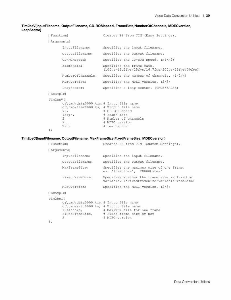
Video Data Conversion Utilities 1-39
Printed:11/19/98 4:16 PM By:SCEA Filename:final44Dataconv.doc Last saved by:SONY On:11/19/98 3:28 PM Comments: Master Copy, TechRef Release 4.3.
Data Conversion Utilities
Tim2bsV(InputFilename, OutputFilename, CD-ROMspeed, FrameRate,NumberOfChannels, MDECversion,LeapSector)
>)XQFWLRQ@ &UHDWHV#%6#IURP#7,0#+(DV\#6HWWLQJV,1
>$UJXPHQWV@
,QSXW)LOHQDPH=# 6SHFLILHV#WKH#LQSXW#ILOHQDPH1
2XWSXW)LOHQDPH= 6SHFLILHV#WKH#RXWSXW#ILOHQDPH1
&'0520VSHHG= 6SHFLILHV#WKH#&'0520#VSHHG1#+[42[5,
)UDPH5DWH= 6SHFLILHV#WKH#IUDPH#UDWH1+43ISV24518ISV248ISV2491:ISV253ISV258ISV263ISV,
1XPEHU2I&KDQQHOV= 6SHFLILHV#WKH#QXPEHU#RI#FKDQQHOV1#+42527,
0'(&YHUVLRQ= 6SHFLILHV#WKH#0'(&#YHUVLRQ1#+526,
/HDS6HFWRU= 6SHFLILHV#D#OHDS#VHFWRU1#+758(2)$/6(,
>([DPSOH@
7LP5EV9+F=?WPS?GDWD33331WLP/&#,QSXW#ILOH#QDPHF=?WPS?WLPY33331EV/ XWSXW#ILOH#QDPH[5/ &#&'0520#VSHHG48ISV/ &#)UDPH#UDWH5/ XPEHU#RI#FKDQQHOV5/ �'(&#YHUVLRQ758( &#/HDS6HFWRU
,>
Tim2bsC(InputFilename, OutputFilename, MaxFrameSize,FixedFrameSize, MDECversion)
>)XQFWLRQ@ &UHDWHV#%6#IURP#7,0#+&XVWRP#6HWWLQJV,1
>$UJXPHQWV@
,QSXW)LOHQDPH=# 6SHFLILHV#WKH#LQSXW#ILOHQDPH1
2XWSXW)LOHQDPH= 6SHFLILHV#WKH#RXWSXW#ILOHQDPH1
0D[)UDPH6L]H= 6SHFLILHV#WKH#PD[LPXP#VL]H#RI#RQH#IUDPH1H[1#*43VHFWRUV*/#*53333E\WHV*
)L[HG)UDPH6L]H= 6SHFLILHV#ZKHWKHU#WKH#IUDPH#VL]H#LV#IL[HG#RUYDULDEOH1#+*)L[HG)UDPH6L]H29DULDEOH)UDPH6L]H,
0'(&YHUVLRQ= 6SHFLILHV#WKH#0'(&#YHUVLRQ1#+526,
>([DPSOH@
7LP5EV&+F=?WPS?GDWD33331WLP/&#,QSXW#ILOH#QDPHF=?WPS?DYLF33331EV/ XWSXW#ILOH#QDPH43VHFWRUV/ �D[LPXP#VL]H#IRU#RQH#IUDPH)L[HG)UDPH6L]H/ &#)L[HG#IUDPH#VL]H#RU#QRW5 �'(&#YHUVLRQ
,>
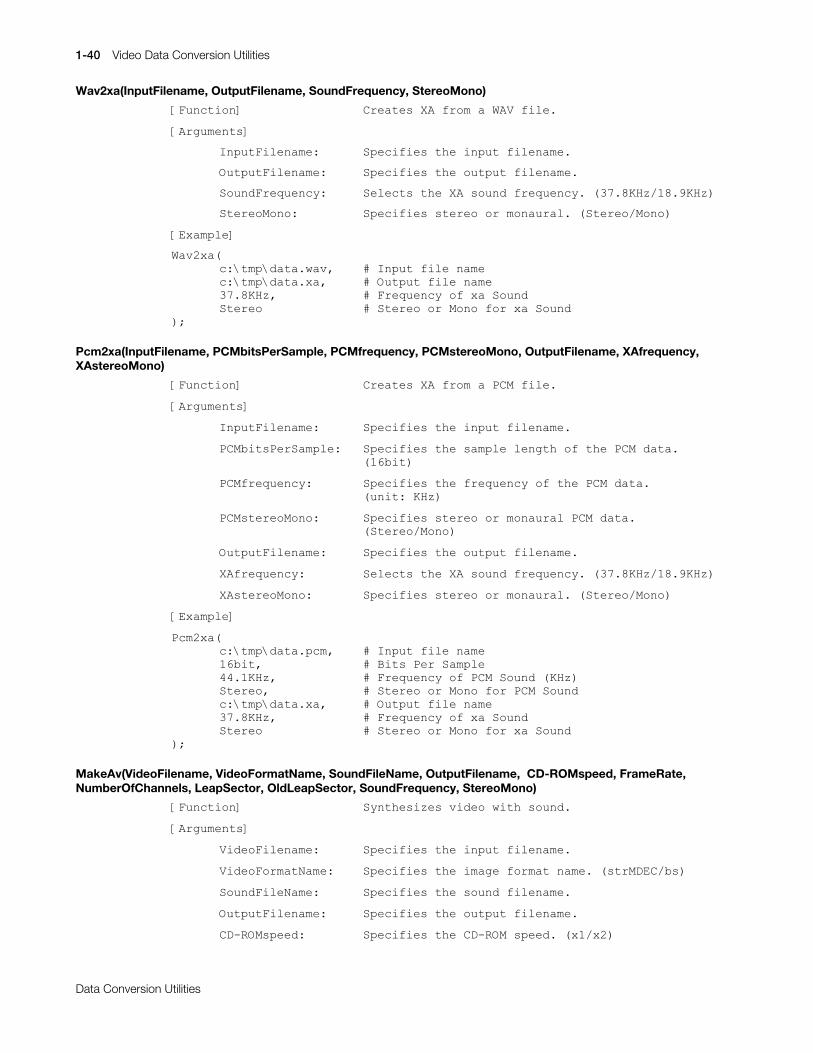
1-40 Video Data Conversion Utilities
Printed:11/19/98 4:16 PM By:SCEA Filename:final44Dataconv.doc Last saved by:SONY On:11/19/98 3:28 PM Comments: Master Copy, TechRef Release 4.3.
Data Conversion Utilities
Wav2xa(InputFilename, OutputFilename, SoundFrequency, StereoMono)
>)XQFWLRQ@# &UHDWHV#;$#IURP#D#:$9#ILOH1
>$UJXPHQWV@
,QSXW)LOHQDPH=# 6SHFLILHV#WKH#LQSXW#ILOHQDPH1
2XWSXW)LOHQDPH= 6SHFLILHV#WKH#RXWSXW#ILOHQDPH1
6RXQG)UHTXHQF\= 6HOHFWV#WKH#;$#VRXQG#IUHTXHQF\1#+6:1;.+]24;1<.+],
6WHUHR0RQR= 6SHFLILHV#VWHUHR#RU#PRQDXUDO1#+6WHUHR20RQR,
>([DPSOH@
:DY5[D+F=?WPS?GDWD1ZDY/ &#,QSXW#ILOH#QDPHF=?WPS?GDWD1[D/ XWSXW#ILOH#QDPH6:1;.+]/ &#)UHTXHQF\#RI#[D#6RXQG6WHUHR WHUHR#RU#0RQR#IRU#[D#6RXQG
,>
Pcm2xa(InputFilename, PCMbitsPerSample, PCMfrequency, PCMstereoMono, OutputFilename, XAfrequency,XAstereoMono)
>)XQFWLRQ@ &UHDWHV#;$#IURP#D#3&0#ILOH1
>$UJXPHQWV@
,QSXW)LOHQDPH=# 6SHFLILHV#WKH#LQSXW#ILOHQDPH1
3&0ELWV3HU6DPSOH= 6SHFLILHV#WKH#VDPSOH#OHQJWK#RI#WKH#3&0#GDWD1+49ELW,
3&0IUHTXHQF\= 6SHFLILHV#WKH#IUHTXHQF\#RI#WKH#3&0#GDWD1+XQLW=#.+],
3&0VWHUHR0RQR= 6SHFLILHV#VWHUHR#RU#PRQDXUDO#3&0#GDWD1+6WHUHR20RQR,
2XWSXW)LOHQDPH= 6SHFLILHV#WKH#RXWSXW#ILOHQDPH1
;$IUHTXHQF\= 6HOHFWV#WKH#;$#VRXQG#IUHTXHQF\1#+6:1;.+]24;1<.+],
;$VWHUHR0RQR= 6SHFLILHV#VWHUHR#RU#PRQDXUDO1#+6WHUHR20RQR,
>([DPSOH@
3FP5[D+F=?WPS?GDWD1SFP/ &#,QSXW#ILOH#QDPH49ELW/ &#%LWV#3HU#6DPSOH7714.+]/ &#)UHTXHQF\#RI#3&0#6RXQG#+.+],6WHUHR/ WHUHR#RU#0RQR#IRU#3&0#6RXQGF=?WPS?GDWD1[D/ XWSXW#ILOH#QDPH6:1;.+]/ &#)UHTXHQF\#RI#[D#6RXQG6WHUHR WHUHR#RU#0RQR#IRU#[D#6RXQG
,>
MakeAv(VideoFilename, VideoFormatName, SoundFileName, OutputFilename, CD-ROMspeed, FrameRate,NumberOfChannels, LeapSector, OldLeapSector, SoundFrequency, StereoMono)
>)XQFWLRQ@ 6\QWKHVL]HV#YLGHR#ZLWK#VRXQG1
>$UJXPHQWV@
9LGHR)LOHQDPH=# 6SHFLILHV#WKH#LQSXW#ILOHQDPH1
9LGHR)RUPDW1DPH= 6SHFLILHV#WKH#LPDJH#IRUPDW#QDPH1#+VWU0'(&2EV,
6RXQG)LOH1DPH= 6SHFLILHV#WKH#VRXQG#ILOHQDPH1
2XWSXW)LOHQDPH= 6SHFLILHV#WKH#RXWSXW#ILOHQDPH1
&'0520VSHHG= 6SHFLILHV#WKH#&'0520#VSHHG1#+[42[5,
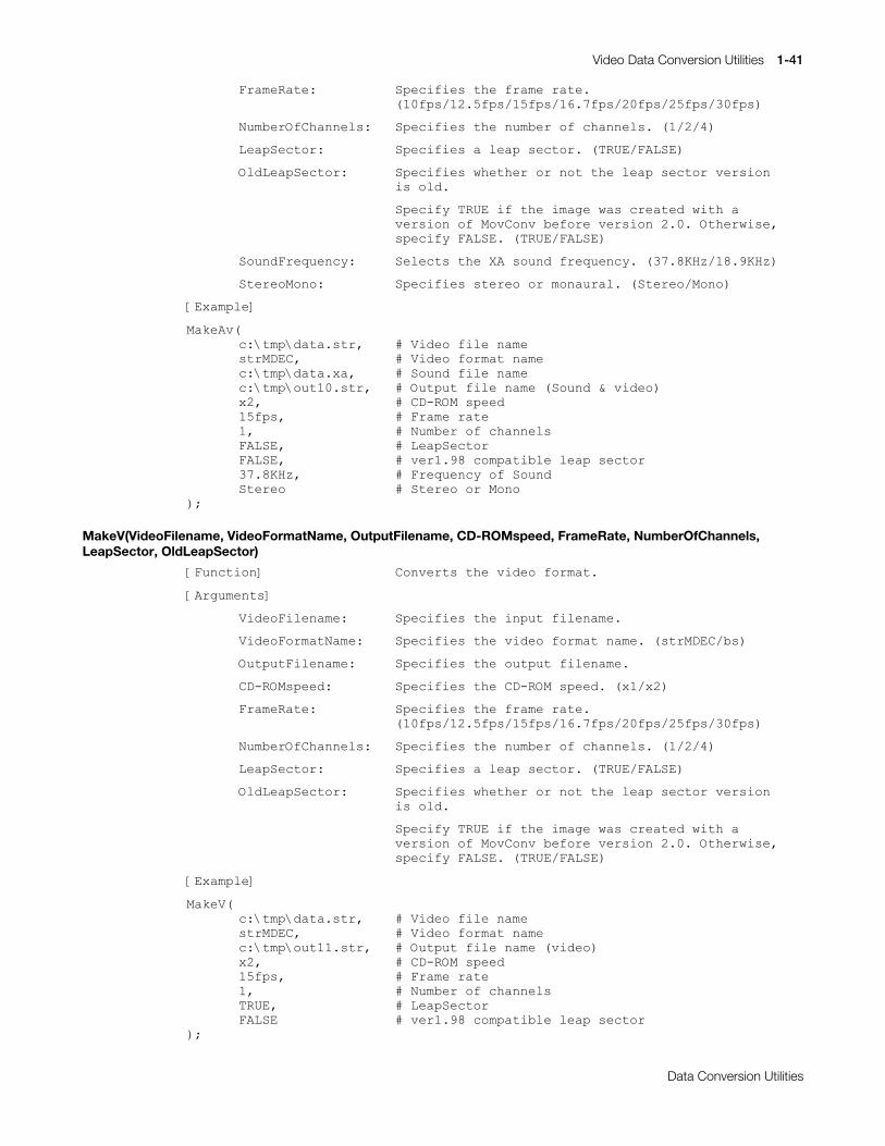
Video Data Conversion Utilities 1-41
Printed:11/19/98 4:16 PM By:SCEA Filename:final44Dataconv.doc Last saved by:SONY On:11/19/98 3:28 PM Comments: Master Copy, TechRef Release 4.3.
Data Conversion Utilities
)UDPH5DWH= 6SHFLILHV#WKH#IUDPH#UDWH1+43ISV24518ISV248ISV2491:ISV253ISV258ISV263ISV,
1XPEHU2I&KDQQHOV= 6SHFLILHV#WKH#QXPEHU#RI#FKDQQHOV1#+42527,
/HDS6HFWRU= 6SHFLILHV#D#OHDS#VHFWRU1#+758(2)$/6(,
2OG/HDS6HFWRU= 6SHFLILHV#ZKHWKHU#RU#QRW#WKH#OHDS#VHFWRU#YHUVLRQ#LV#ROG1
6SHFLI\#758(#LI#WKH#LPDJH#ZDV#FUHDWHG#ZLWK#DYHUVLRQ#RI#0RY&RQY#EHIRUH#YHUVLRQ#5131#2WKHUZLVH/VSHFLI\#)$/6(1#+758(2)$/6(,
6RXQG)UHTXHQF\= 6HOHFWV#WKH#;$#VRXQG#IUHTXHQF\1#+6:1;.+]24;1<.+],
6WHUHR0RQR= 6SHFLILHV#VWHUHR#RU#PRQDXUDO1#+6WHUHR20RQR,
>([DPSOH@
0DNH$Y+F=?WPS?GDWD1VWU/ 	LGHR#ILOH#QDPHVWU0'(&/ 	LGHR#IRUPDW#QDPHF=?WPS?GDWD1[D/ RXQG#ILOH#QDPHF=?WPS?RXW431VWU/ XWSXW#ILOH#QDPH#+6RXQG#)#YLGHR,[5/ &#&'0520#VSHHG48ISV/ &#)UDPH#UDWH4/ XPEHU#RI#FKDQQHOV)$/6(/ &#/HDS6HFWRU)$/6(/ &#YHU41<;#FRPSDWLEOH#OHDS#VHFWRU6:1;.+]/ &#)UHTXHQF\#RI#6RXQG6WHUHR WHUHR#RU#0RQR
,>
MakeV(VideoFilename, VideoFormatName, OutputFilename, CD-ROMspeed, FrameRate, NumberOfChannels,LeapSector, OldLeapSector)
>)XQFWLRQ@ &RQYHUWV#WKH#YLGHR#IRUPDW1
>$UJXPHQWV@
9LGHR)LOHQDPH=# 6SHFLILHV#WKH#LQSXW#ILOHQDPH1
9LGHR)RUPDW1DPH= 6SHFLILHV#WKH#YLGHR#IRUPDW#QDPH1#+VWU0'(&2EV,
2XWSXW)LOHQDPH= 6SHFLILHV#WKH#RXWSXW#ILOHQDPH1
&'0520VSHHG= 6SHFLILHV#WKH#&'0520#VSHHG1#+[42[5,
)UDPH5DWH= 6SHFLILHV#WKH#IUDPH#UDWH1+43ISV24518ISV248ISV2491:ISV253ISV258ISV263ISV,
1XPEHU2I&KDQQHOV= 6SHFLILHV#WKH#QXPEHU#RI#FKDQQHOV1#+42527,
/HDS6HFWRU= 6SHFLILHV#D#OHDS#VHFWRU1#+758(2)$/6(,
2OG/HDS6HFWRU= 6SHFLILHV#ZKHWKHU#RU#QRW#WKH#OHDS#VHFWRU#YHUVLRQ#LV#ROG1
6SHFLI\#758(#LI#WKH#LPDJH#ZDV#FUHDWHG#ZLWK#D#YHUVLRQ#RI#0RY&RQY#EHIRUH#YHUVLRQ#5131#2WKHUZLVH/VSHFLI\#)$/6(1#+758(2)$/6(,
>([DPSOH@
0DNH9+F=?WPS?GDWD1VWU/ 	LGHR#ILOH#QDPHVWU0'(&/ 	LGHR#IRUPDW#QDPHF=?WPS?RXW441VWU/ XWSXW#ILOH#QDPH#+YLGHR,[5/ &#&'0520#VSHHG48ISV/ &#)UDPH#UDWH4/ XPEHU#RI#FKDQQHOV758(/ &#/HDS6HFWRU)$/6( &#YHU41<;#FRPSDWLEOH#OHDS#VHFWRU
,>
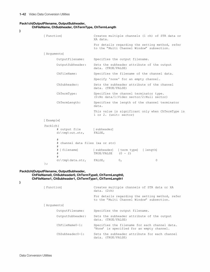
1-42 Video Data Conversion Utilities
Printed:11/19/98 4:16 PM By:SCEA Filename:final44Dataconv.doc Last saved by:SONY On:11/19/98 3:28 PM Comments: Master Copy, TechRef Release 4.3.
Data Conversion Utilities
Pack1ch(OutputFilename, OutputSubheader,ChFileName, ChSubheader, ChTermType, ChTermLength
)
>)XQFWLRQ@ &UHDWHV#PXOWLSOH#FKDQQHOV#+4#FK,#RI#675#GDWD#RU#;$#GDWD1
)RU#GHWDLOV#UHJDUGLQJ#WKH#VHWWLQJ#PHWKRG/#UHIHU#WR#WKH#«0XOWL#&KDQQHO#:LQGRZ¬#VXEVHFWLRQ1
>$UJXPHQWV@
2XWSXW)LOHQDPH=# 6SHFLILHV#WKH#RXWSXW#ILOHQDPH1
2XWSXW6XEKHDGHU= 6HWV#WKH#VXEKHDGHU#DWWULEXWH#RI#WKH#RXWSXWGDWD1#+758(2)$/6(,
&K)LOH1DPH= 6SHFLILHV#WKH#ILOHQDPH#RI#WKH#FKDQQHO#GDWD1
6SHFLI\#*QRQH*#IRU#DQ#HPSW\#FKDQQHO1
&K6XEKHDGHU= 6HWV#WKH#VXEKHDGHU#DWWULEXWH#RI#WKH#FKDQQHOGDWD1#+758(2)$/6(,
&K7HUP7\SH= 6SHFLILHV#WKH#FKDQQHO#WHUPLQDWRU#W\SH1+3=1R#GDWD24=9LGHR#VHFWRU25=1XOO#VHFWRU,
&K7HUP/HQJWK= 6SHFLILHV#WKH#OHQJWK#RI#WKH#FKDQQHO#WHUPLQDWRUGDWD1
7KLV#YDOXH#LV#VLJQLILFDQW#RQO\#ZKHQ#&K7HUP7\SH#LV4#RU#51#+XQLW=#VHFWRU,
>([DPSOH@
3DFN4FK+&#RXWSXW#ILOH >VXEKHDGHU@G=?WPS?RXW1VWU/ )$/6(/
&&#FKDQQHO#GDWD#ILOHV#+[D#RU#VWU,&&#>ILOHQDPH@ >VXEKHDGHU@ >WHUP#W\SH@ >OHQJWK@& 758(2)$/6( +3#0#5,&G=?WPS?GDWD1VWU/ )$/6(/ 3/ 3
,>
Pack2ch(OutputFilename, OutputSubheader,ChFileName0, ChSubheader0, ChTermType0, ChTermLength0,ChFileName1, ChSubheader1, ChTermType1, ChTermLength1
)
>)XQFWLRQ@ &UHDWHV#PXOWLSOH#FKDQQHOV#RI#675#GDWD#RU#;$GDWD1#+5FK,
)RU#GHWDLOV#UHJDUGLQJ#WKH#VHWWLQJ#PHWKRG/#UHIHU#WR#WKH#«0XOWL#&KDQQHO#:LQGRZ¬#VXEVHFWLRQ1
>$UJXPHQWV@
2XWSXW)LOHQDPH=# 6SHFLILHV#WKH#RXWSXW#ILOHQDPH1
2XWSXW6XEKHDGHU= 6HWV#WKH#VXEKHDGHU#DWWULEXWH#RI#WKH#RXWSXWGDWD1#+758(2)$/6(,
&K)LOH1DPH304= 6SHFLILHV#WKH#ILOHQDPH#IRU#HDFK#FKDQQHO#GDWD11RQH®#LV#VSHFLILHG#IRU#DQ#HPSW\#FKDQQHO1
&K6XEKHDGHU304= 6HWV#WKH#VXEKHDGHU#DWWULEXWH#IRU#HDFK#FKDQQHOGDWD1#+758(2)$/6(,
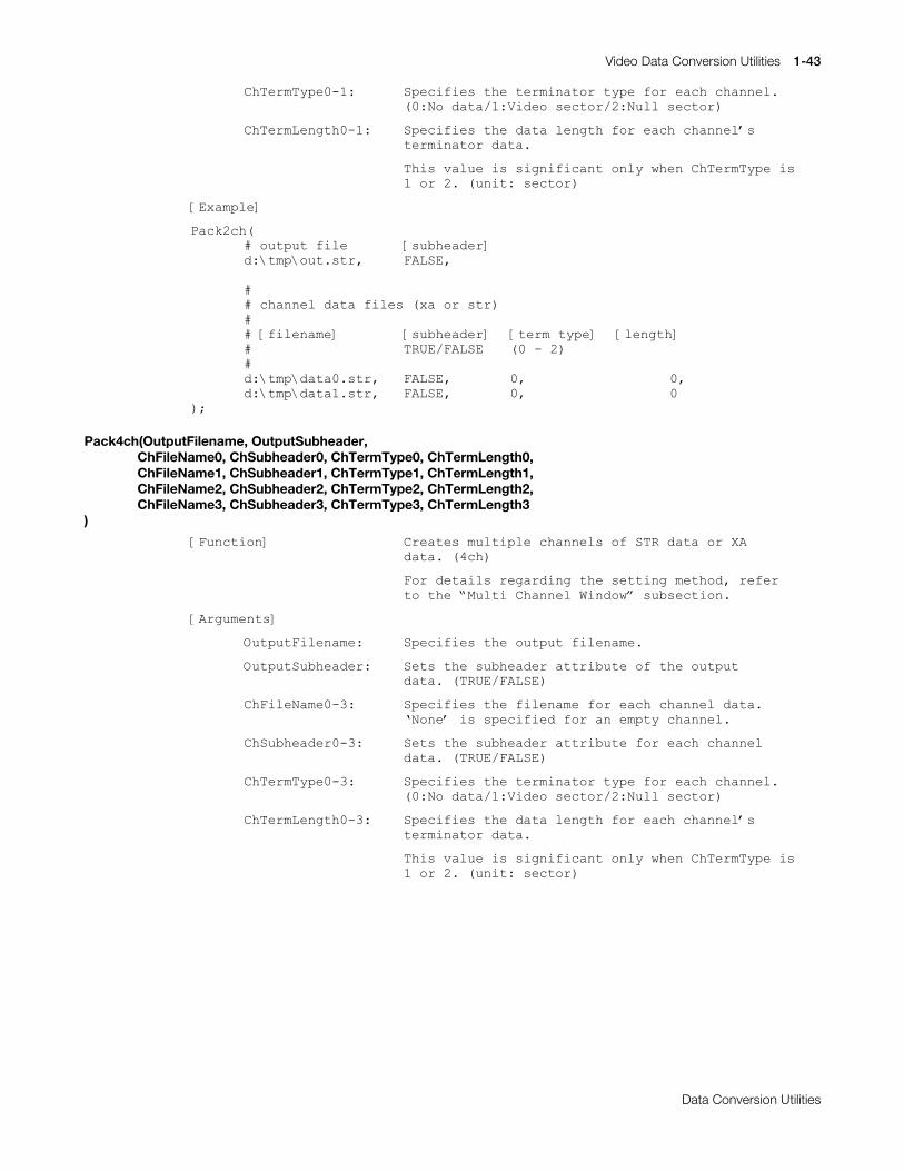
Video Data Conversion Utilities 1-43
Printed:11/19/98 4:16 PM By:SCEA Filename:final44Dataconv.doc Last saved by:SONY On:11/19/98 3:28 PM Comments: Master Copy, TechRef Release 4.3.
Data Conversion Utilities
&K7HUP7\SH304= 6SHFLILHV#WKH#WHUPLQDWRU#W\SH#IRU#HDFK#FKDQQHO1+3=1R#GDWD24=9LGHR#VHFWRU25=1XOO#VHFWRU,
&K7HUP/HQJWK304= 6SHFLILHV#WKH#GDWD#OHQJWK#IRU#HDFK#FKDQQHO®VWHUPLQDWRU#GDWD1
7KLV#YDOXH#LV#VLJQLILFDQW#RQO\#ZKHQ#&K7HUP7\SH#LV4#RU#51#+XQLW=#VHFWRU,
>([DPSOH@
3DFN5FK+&#RXWSXW#ILOH >VXEKHDGHU@G=?WPS?RXW1VWU/ )$/6(/
&&#FKDQQHO#GDWD#ILOHV#+[D#RU#VWU,&&#>ILOHQDPH@ >VXEKHDGHU@ >WHUP#W\SH@ >OHQJWK@& 758(2)$/6( +3#0#5,&G=?WPS?GDWD31VWU/ )$/6(/ 3/ 3/G=?WPS?GDWD41VWU/ )$/6(/ 3/ 3
,>
Pack4ch(OutputFilename, OutputSubheader,ChFileName0, ChSubheader0, ChTermType0, ChTermLength0,ChFileName1, ChSubheader1, ChTermType1, ChTermLength1,ChFileName2, ChSubheader2, ChTermType2, ChTermLength2,ChFileName3, ChSubheader3, ChTermType3, ChTermLength3
)
>)XQFWLRQ@ &UHDWHV#PXOWLSOH#FKDQQHOV#RI#675#GDWD#RU#;$GDWD1#+7FK,
)RU#GHWDLOV#UHJDUGLQJ#WKH#VHWWLQJ#PHWKRG/#UHIHU#WR#WKH#«0XOWL#&KDQQHO#:LQGRZ¬#VXEVHFWLRQ1
>$UJXPHQWV@
2XWSXW)LOHQDPH=# 6SHFLILHV#WKH#RXWSXW#ILOHQDPH1
2XWSXW6XEKHDGHU= 6HWV#WKH#VXEKHDGHU#DWWULEXWH#RI#WKH#RXWSXWGDWD1#+758(2)$/6(,
&K)LOH1DPH306= 6SHFLILHV#WKH#ILOHQDPH#IRU#HDFK#FKDQQHO#GDWD11RQH®#LV#VSHFLILHG#IRU#DQ#HPSW\#FKDQQHO1
&K6XEKHDGHU306= 6HWV#WKH#VXEKHDGHU#DWWULEXWH#IRU#HDFK#FKDQQHOGDWD1#+758(2)$/6(,
&K7HUP7\SH306= 6SHFLILHV#WKH#WHUPLQDWRU#W\SH#IRU#HDFK#FKDQQHO1+3=1R#GDWD24=9LGHR#VHFWRU25=1XOO#VHFWRU,
&K7HUP/HQJWK306= 6SHFLILHV#WKH#GDWD#OHQJWK#IRU#HDFK#FKDQQHO®VWHUPLQDWRU#GDWD1
7KLV#YDOXH#LV#VLJQLILFDQW#RQO\#ZKHQ#&K7HUP7\SH#LV4#RU#51#+XQLW=#VHFWRU,
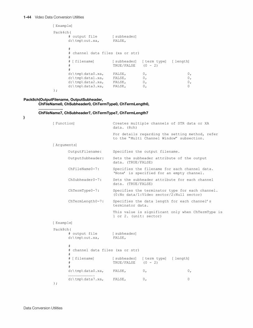
1-44 Video Data Conversion Utilities
Printed:11/19/98 4:16 PM By:SCEA Filename:final44Dataconv.doc Last saved by:SONY On:11/19/98 3:28 PM Comments: Master Copy, TechRef Release 4.3.
Data Conversion Utilities
>([DPSOH@
3DFN7FK+&#RXWSXW#ILOH >VXEKHDGHU@G=?WPS?RXW1[D/ )$/6(/
&&#FKDQQHO#GDWD#ILOHV#+[D#RU#VWU,&&#>ILOHQDPH@ >VXEKHDGHU@ >WHUP#W\SH@ >OHQJWK@& 758(2)$/6( +3#0#5,&G=?WPS?GDWD31[D/ )$/6(/ 3/ 3/G=?WPS?GDWD41[D/ )$/6(/ 3/ 3/G=?WPS?GDWD51[D/ )$/6(/ 3/ 3/G=?WPS?GDWD61[D/ )$/6(/ 3/ 3
,>
Pack8ch(OutputFilename, OutputSubheader,ChFileName0, ChSubheader0, ChTermType0, ChTermLength0,………………..ChFileName7, ChSubheader7, ChTermType7, ChTermLength7
)
>)XQFWLRQ@ &UHDWHV#PXOWLSOH#FKDQQHOV#RI#675#GDWD#RU#;$GDWD1#+;FK,
)RU#GHWDLOV#UHJDUGLQJ#WKH#VHWWLQJ#PHWKRG/#UHIHUWR#WKH#«0XOWL#&KDQQHO#:LQGRZ¬#VXEVHFWLRQ1
>$UJXPHQWV@
2XWSXW)LOHQDPH=# 6SHFLILHV#WKH#RXWSXW#ILOHQDPH1
2XWSXW6XEKHDGHU= 6HWV#WKH#VXEKHDGHU#DWWULEXWH#RI#WKH#RXWSXWGDWD1#+758(2)$/6(,
&K)LOH1DPH30:= 6SHFLILHV#WKH#ILOHQDPH#IRU#HDFK#FKDQQHO#GDWD11RQH®#LV#VSHFLILHG#IRU#DQ#HPSW\#FKDQQHO1
&K6XEKHDGHU30:= 6HWV#WKH#VXEKHDGHU#DWWULEXWH#IRU#HDFK#FKDQQHOGDWD1#+758(2)$/6(,
&K7HUP7\SH30:= 6SHFLILHV#WKH#WHUPLQDWRU#W\SH#IRU#HDFK#FKDQQHO1+3=1R#GDWD24=9LGHR#VHFWRU25=1XOO#VHFWRU,
&K7HUP/HQJWK30:= 6SHFLILHV#WKH#GDWD#OHQJWK#IRU#HDFK#FKDQQHO®VWHUPLQDWRU#GDWD1
7KLV#YDOXH#LV#VLJQLILFDQW#RQO\#ZKHQ#&K7HUP7\SH#LV4#RU#51#+XQLW=#VHFWRU,
>([DPSOH@
3DFN;FK+&#RXWSXW#ILOH >VXEKHDGHU@G=?WPS?RXW1[D/ )$/6(/
&&#FKDQQHO#GDWD#ILOHV#+[D#RU#VWU,&&#>ILOHQDPH@ >VXEKHDGHU@ >WHUP#W\SH@ >OHQJWK@& 758(2)$/6( +3#0#5,&G=?WPS?GDWD31[D/ )$/6(/ 3/ 3/£££££££££££1G=?WPS?GDWD:1[D/ )$/6(/ 3/ 3
,>
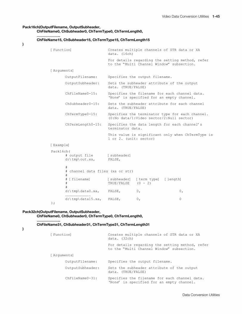
Video Data Conversion Utilities 1-45
Printed:11/19/98 4:16 PM By:SCEA Filename:final44Dataconv.doc Last saved by:SONY On:11/19/98 3:28 PM Comments: Master Copy, TechRef Release 4.3.
Data Conversion Utilities
Pack16ch(OutputFilename, OutputSubheader,ChFileName0, ChSubheader0, ChTermType0, ChTermLength0,………………..ChFileName15, ChSubheader15, ChTermType15, ChTermLength15
)
>)XQFWLRQ@ &UHDWHV#PXOWLSOH#FKDQQHOV#RI#675#GDWD#RU#;$GDWD1#+49FK,
)RU#GHWDLOV#UHJDUGLQJ#WKH#VHWWLQJ#PHWKRG/#UHIHUWR#WKH#«0XOWL#&KDQQHO#:LQGRZ¬#VXEVHFWLRQ1
>$UJXPHQWV@
2XWSXW)LOHQDPH=# 6SHFLILHV#WKH#RXWSXW#ILOHQDPH1
2XWSXW6XEKHDGHU= 6HWV#WKH#VXEKHDGHU#DWWULEXWH#RI#WKH#RXWSXWGDWD1#+758(2)$/6(,
&K)LOH1DPH3048= 6SHFLILHV#WKH#ILOHQDPH#IRU#HDFK#FKDQQHO#GDWD11RQH®#LV#VSHFLILHG#IRU#DQ#HPSW\#FKDQQHO1
&K6XEKHDGHU3048= 6HWV#WKH#VXEKHDGHU#DWWULEXWH#IRU#HDFK#FKDQQHOGDWD1#+758(2)$/6(,
&K7HUP7\SH3048= 6SHFLILHV#WKH#WHUPLQDWRU#W\SH#IRU#HDFK#FKDQQHO1+3=1R#GDWD24=9LGHR#VHFWRU25=1XOO#VHFWRU,
&K7HUP/HQJWK3048= 6SHFLILHV#WKH#GDWD#OHQJWK#IRU#HDFK#FKDQQHO®VWHUPLQDWRU#GDWD1
7KLV#YDOXH#LV#VLJQLILFDQW#RQO\#ZKHQ#&K7HUP7\SH#LV4#RU#51#+XQLW=#VHFWRU,
>([DPSOH@
3DFN49FK+&#RXWSXW#ILOH >VXEKHDGHU@G=?WPS?RXW1[D/ )$/6(/
&&#FKDQQHO#GDWD#ILOHV#+[D#RU#VWU,&&#>ILOHQDPH@ >VXEKHDGHU@ >WHUP#W\SH@ >OHQJWK@& 758(2)$/6( +3#0#5,&G=?WPS?GDWD31[D/ )$/6(/ 3/ 3/£££££££££££1G=?WPS?GDWD481[D/ )$/6(/ 3/ 3
,>
Pack32ch(OutputFilename, OutputSubheader,ChFileName0, ChSubheader0, ChTermType0, ChTermLength0,………………..ChFileName31, ChSubheader31, ChTermType31, ChTermLength31
)
>)XQFWLRQ@ &UHDWHV#PXOWLSOH#FKDQQHOV#RI#675#GDWD#RU#;$GDWD1#+65FK,
)RU#GHWDLOV#UHJDUGLQJ#WKH#VHWWLQJ#PHWKRG/#UHIHUWR#WKH#«0XOWL#&KDQQHO#:LQGRZ¬#VXEVHFWLRQ1
>$UJXPHQWV@
2XWSXW)LOHQDPH=# 6SHFLILHV#WKH#RXWSXW#ILOHQDPH1
2XWSXW6XEKHDGHU= 6HWV#WKH#VXEKHDGHU#DWWULEXWH#RI#WKH#RXWSXWGDWD1#+758(2)$/6(,
&K)LOH1DPH3064= 6SHFLILHV#WKH#ILOHQDPH#IRU#HDFK#FKDQQHO#GDWD11RQH®#LV#VSHFLILHG#IRU#DQ#HPSW\#FKDQQHO1
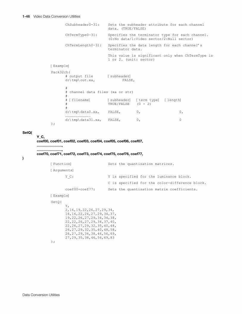
1-46 Video Data Conversion Utilities
Printed:11/19/98 4:16 PM By:SCEA Filename:final44Dataconv.doc Last saved by:SONY On:11/19/98 3:28 PM Comments: Master Copy, TechRef Release 4.3.
Data Conversion Utilities
&K6XEKHDGHU3064= 6HWV#WKH#VXEKHDGHU#DWWULEXWH#IRU#HDFK#FKDQQHOGDWD1#+758(2)$/6(,
&K7HUP7\SH3064= 6SHFLILHV#WKH#WHUPLQDWRU#W\SH#IRU#HDFK#FKDQQHO1+3=1R#GDWD24=9LGHR#VHFWRU25=1XOO#VHFWRU,
&K7HUP/HQJWK3064= 6SHFLILHV#WKH#GDWD#OHQJWK#IRU#HDFK#FKDQQHO®VWHUPLQDWRU#GDWD1
7KLV#YDOXH#LV#VLJQLILFDQW#RQO\#ZKHQ#&K7HUP7\SH#LV4#RU#51#+XQLW=#VHFWRU,
>([DPSOH@
3DFN65FK+&#RXWSXW#ILOH >VXEKHDGHU@G=?WPS?RXW1[D/ )$/6(/
&&#FKDQQHO#GDWD#ILOHV#+[D#RU#VWU,&&#>ILOHQDPH@ >VXEKHDGHU@ >WHUP#W\SH@ >OHQJWK@& 758(2)$/6( +3#0#5,&G=?WPS?GDWD31[D/ )$/6(/ 3/ 3/£££££££££££1G=?WPS?GDWD641[D/ )$/6(/ 3/ 3
,>
SetQ(Y_C,coef00, coef01, coef02, coef03, coef04, coef05, coef06, coef07,…………………,…………………,coef70, coef71, coef72, coef73, coef74, coef75, coef76, coef77,
)
>)XQFWLRQ@ 6HWV#WKH#TXDQWL]DWLRQ#PDWULFHV1
>$UJXPHQWV@
<B&= <#LV#VSHFLILHG#IRU#WKH#OXPLQDQFH#EORFN1
&#LV#VSHFLILHG#IRU#WKH#FRORU0GLIIHUHQFH#EORFN1
FRHI330FRHI::= 6HWV#WKH#TXDQWL]DWLRQ#PDWUL[#FRHIILFLHQWV1
>([DPSOH@
6HW4+</5/49/4</55/59/5:/5</67/49/49/55/57/5:/5</67/6:/4</55/59/5:/5</67/67/6;/55/55/59/5:/5</67/6:/73/55/59/5:/5</65/68/73/7;/59/5:/5</65/68/73/7;/8;/59/5:/5</67/6;/79/89/9</5:/5</68/6;/79/89/9</;6
,>
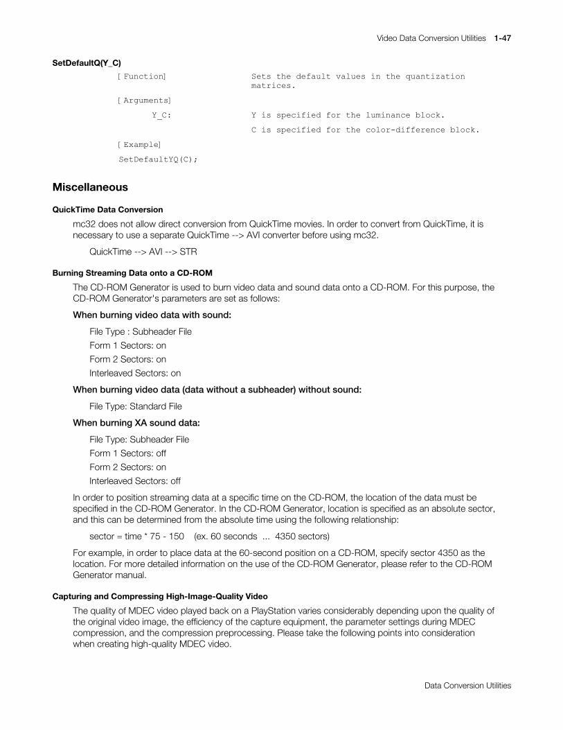
Video Data Conversion Utilities 1-47
Printed:11/19/98 4:16 PM By:SCEA Filename:final44Dataconv.doc Last saved by:SONY On:11/19/98 3:28 PM Comments: Master Copy, TechRef Release 4.3.
Data Conversion Utilities
SetDefaultQ(Y_C)
>)XQFWLRQ@ 6HWV#WKH#GHIDXOW#YDOXHV#LQ#WKH#TXDQWL]DWLRQPDWULFHV1
>$UJXPHQWV@
<B&= <#LV#VSHFLILHG#IRU#WKH#OXPLQDQFH#EORFN1
&#LV#VSHFLILHG#IRU#WKH#FRORU0GLIIHUHQFH#EORFN1
>([DPSOH@
6HW'HIDXOW<4+&,>
Miscellaneous
QuickTime Data Conversion
mc32 does not allow direct conversion from QuickTime movies. In order to convert from QuickTime, it isnecessary to use a separate QuickTime --> AVI converter before using mc32.
QuickTime --> AVI --> STR
Burning Streaming Data onto a CD-ROM
The CD-ROM Generator is used to burn video data and sound data onto a CD-ROM. For this purpose, theCD-ROM Generator's parameters are set as follows:
When burning video data with sound:
File Type : Subheader File
Form 1 Sectors: on
Form 2 Sectors: on
Interleaved Sectors: on
When burning video data (data without a subheader) without sound:
File Type: Standard File
When burning XA sound data:
File Type: Subheader File
Form 1 Sectors: off
Form 2 Sectors: on
Interleaved Sectors: off
In order to position streaming data at a specific time on the CD-ROM, the location of the data must bespecified in the CD-ROM Generator. In the CD-ROM Generator, location is specified as an absolute sector,and this can be determined from the absolute time using the following relationship:
sector = time * 75 - 150 (ex. 60 seconds ... 4350 sectors)
For example, in order to place data at the 60-second position on a CD-ROM, specify sector 4350 as thelocation. For more detailed information on the use of the CD-ROM Generator, please refer to the CD-ROMGenerator manual.
Capturing and Compressing High-Image-Quality Video
The quality of MDEC video played back on a PlayStation varies considerably depending upon the quality ofthe original video image, the efficiency of the capture equipment, the parameter settings during MDECcompression, and the compression preprocessing. Please take the following points into considerationwhen creating high-quality MDEC video.
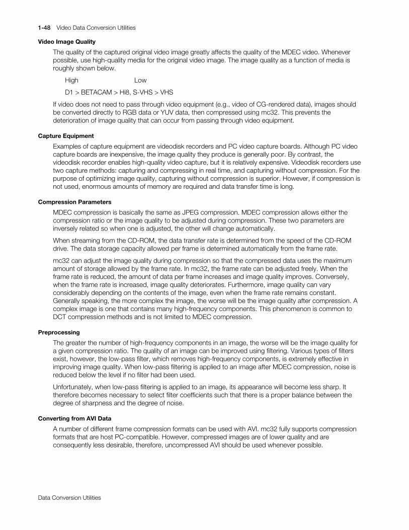
1-48 Video Data Conversion Utilities
Printed:11/19/98 4:16 PM By:SCEA Filename:final44Dataconv.doc Last saved by:SONY On:11/19/98 3:28 PM Comments: Master Copy, TechRef Release 4.3.
Data Conversion Utilities
Video Image Quality
The quality of the captured original video image greatly affects the quality of the MDEC video. Wheneverpossible, use high-quality media for the original video image. The image quality as a function of media isroughly shown below.
High Low
D1 > BETACAM > Hi8, S-VHS > VHS
If video does not need to pass through video equipment (e.g., video of CG-rendered data), images shouldbe converted directly to RGB data or YUV data, then compressed using mc32. This prevents thedeterioration of image quality that can occur from passing through video equipment.
Capture Equipment
Examples of capture equipment are videodisk recorders and PC video capture boards. Although PC videocapture boards are inexpensive, the image quality they produce is generally poor. By contrast, thevideodisk recorder enables high-quality video capture, but it is relatively expensive. Videodisk recorders usetwo capture methods: capturing and compressing in real time, and capturing without compression. For thepurpose of optimizing image quality, capturing without compression is superior. However, if compression isnot used, enormous amounts of memory are required and data transfer time is long.
Compression Parameters
MDEC compression is basically the same as JPEG compression. MDEC compression allows either thecompression ratio or the image quality to be adjusted during compression. These two parameters areinversely related so when one is adjusted, the other will change automatically.
When streaming from the CD-ROM, the data transfer rate is determined from the speed of the CD-ROMdrive. The data storage capacity allowed per frame is determined automatically from the frame rate.
mc32 can adjust the image quality during compression so that the compressed data uses the maximumamount of storage allowed by the frame rate. In mc32, the frame rate can be adjusted freely. When theframe rate is reduced, the amount of data per frame increases and image quality improves. Conversely,when the frame rate is increased, image quality deteriorates. Furthermore, image quality can varyconsiderably depending on the contents of the image, even when the frame rate remains constant.Generally speaking, the more complex the image, the worse will be the image quality after compression. Acomplex image is one that contains many high-frequency components. This phenomenon is common toDCT compression methods and is not limited to MDEC compression.
Preprocessing
The greater the number of high-frequency components in an image, the worse will be the image quality fora given compression ratio. The quality of an image can be improved using filtering. Various types of filtersexist, however, the low-pass filter, which removes high-frequency components, is extremely effective inimproving image quality. When low-pass filtering is applied to an image after MDEC compression, noise isreduced below the level if no filter had been used.
Unfortunately, when low-pass filtering is applied to an image, its appearance will become less sharp. Ittherefore becomes necessary to select filter coefficients such that there is a proper balance between thedegree of sharpness and the degree of noise.
Converting from AVI Data
A number of different frame compression formats can be used with AVI. mc32 fully supports compressionformats that are host PC-compatible. However, compressed images are of lower quality and areconsequently less desirable, therefore, uncompressed AVI should be used whenever possible.

Video Data Conversion Utilities 1-49
Printed:11/19/98 4:16 PM By:SCEA Filename:final44Dataconv.doc Last saved by:SONY On:11/19/98 3:28 PM Comments: Master Copy, TechRef Release 4.3.
Data Conversion Utilities
MovConv: PlayStation Movie Converter
Version 2.2
Documentation date: 8/6/97
Description
MovConv is a movie converter for the PlayStation. MovConv provides the following features:
x Image conversionx Sound conversionx Linking of images and sound (interleaving)x Execution of conversion and interleave scripts
MovConv handles the following image formats:
Input
Movie format: AVI (uncompressed)
Static image sequences: RGB sequence (RGB files sequenced by filename)YUV sequence (YUV files sequenced by filename)TIM sequence (TIM files sequenced by filename)
Output
Movie formats: STR(MDEC)AVI (uncompressed)
Static image sequences: BS sequence (BS file sequenced by filename)RGB sequence (RGB file sequenced by filename)
The STR (MDEC) and BS sequence output formats are data formats compressed for MDEC.
MovConv handles the following audio formats:
Input
WAV (Windows)PCM
Output
XA (CD-ROM XA)
When converting from WAV or PCM to XA, the sampling frequency and ADPCM compression are alsoconverted.
Interleaving of images and sound is described below.
Input
STR(MDEC) or BS + XA
Output
STR(MDEC)
When converting data in which images and sounds are already linked, e.g. AVI with sound, interleaving willbe performed automatically after the image and sound data are converted. However, if image and sounddata are to be created separately, interleaving must be performed manually. Synchronization betweenimages and sounds cannot be performed during interleaving, so the data must be synchronized beforeconversion.
The scripting feature permits batch processing of multiple conversion and interleave operations. Scriptsmust be written in the format defined by MovConv.
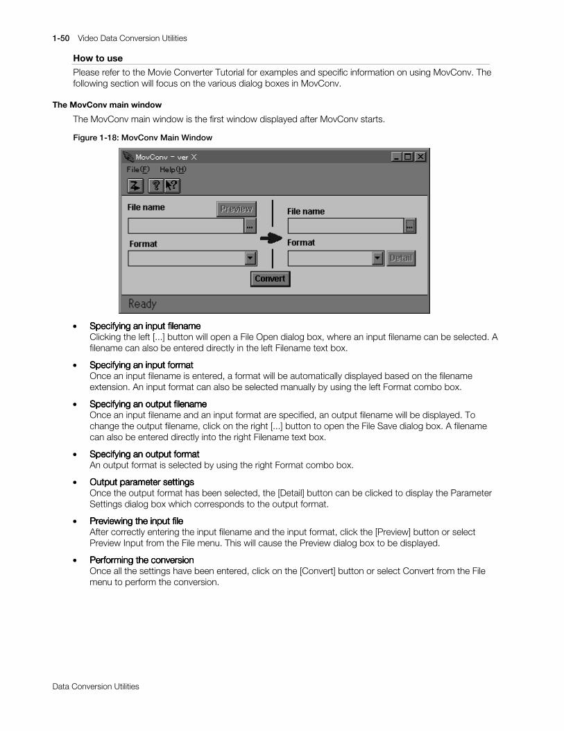
1-50 Video Data Conversion Utilities
Printed:11/19/98 4:16 PM By:SCEA Filename:final44Dataconv.doc Last saved by:SONY On:11/19/98 3:28 PM Comments: Master Copy, TechRef Release 4.3.
Data Conversion Utilities
How to use
Please refer to the Movie Converter Tutorial for examples and specific information on using MovConv. Thefollowing section will focus on the various dialog boxes in MovConv.
The MovConv main window
The MovConv main window is the first window displayed after MovConv starts.
Figure 1-18: MovConv Main Window
x Specifying an input filenameSpecifying an input filenameSpecifying an input filenameSpecifying an input filenameClicking the left [...] button will open a File Open dialog box, where an input filename can be selected. Afilename can also be entered directly in the left Filename text box.
x Specifying an input formatSpecifying an input formatSpecifying an input formatSpecifying an input formatOnce an input filename is entered, a format will be automatically displayed based on the filenameextension. An input format can also be selected manually by using the left Format combo box.
x Specifying an output filenameSpecifying an output filenameSpecifying an output filenameSpecifying an output filenameOnce an input filename and an input format are specified, an output filename will be displayed. Tochange the output filename, click on the right [...] button to open the File Save dialog box. A filenamecan also be entered directly into the right Filename text box.
x Specifying an output formatSpecifying an output formatSpecifying an output formatSpecifying an output formatAn output format is selected by using the right Format combo box.
x Output parameter settingsOutput parameter settingsOutput parameter settingsOutput parameter settingsOnce the output format has been selected, the [Detail] button can be clicked to display the ParameterSettings dialog box which corresponds to the output format.
x Previewing the input filePreviewing the input filePreviewing the input filePreviewing the input fileAfter correctly entering the input filename and the input format, click the [Preview] button or selectPreview Input from the File menu. This will cause the Preview dialog box to be displayed.
x Performing the conversionPerforming the conversionPerforming the conversionPerforming the conversionOnce all the settings have been entered, click on the [Convert] button or select Convert from the Filemenu to perform the conversion.
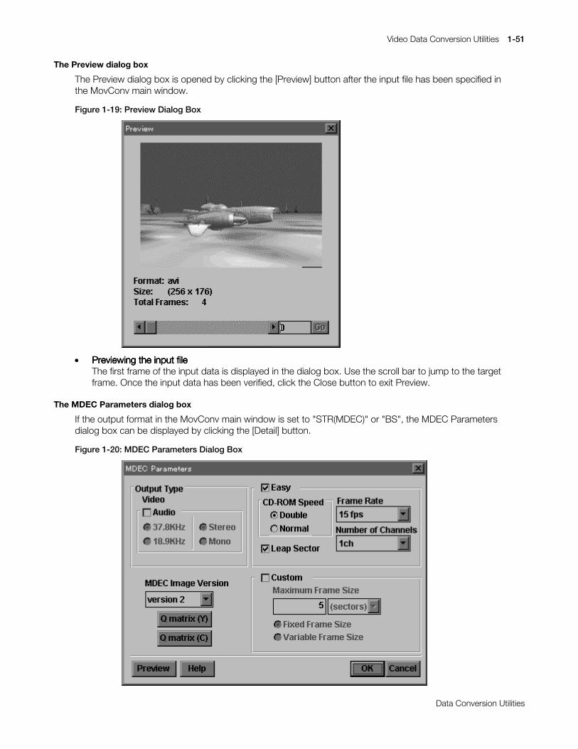
Video Data Conversion Utilities 1-51
Printed:11/19/98 4:16 PM By:SCEA Filename:final44Dataconv.doc Last saved by:SONY On:11/19/98 3:28 PM Comments: Master Copy, TechRef Release 4.3.
Data Conversion Utilities
The Preview dialog box
The Preview dialog box is opened by clicking the [Preview] button after the input file has been specified inthe MovConv main window.
Figure 1-19: Preview Dialog Box
x Previewing the input filePreviewing the input filePreviewing the input filePreviewing the input fileThe first frame of the input data is displayed in the dialog box. Use the scroll bar to jump to the targetframe. Once the input data has been verified, click the Close button to exit Preview.
The MDEC Parameters dialog box
If the output format in the MovConv main window is set to "STR(MDEC)" or "BS", the MDEC Parametersdialog box can be displayed by clicking the [Detail] button.
Figure 1-20: MDEC Parameters Dialog Box

1-52 Video Data Conversion Utilities
Printed:11/19/98 4:16 PM By:SCEA Filename:final44Dataconv.doc Last saved by:SONY On:11/19/98 3:28 PM Comments: Master Copy, TechRef Release 4.3.
Data Conversion Utilities
x Selecting an output typeSelecting an output typeSelecting an output typeSelecting an output typeClick the Audio check box if the output data includes sound (leave the box unchecked if there is nosound). This setting only applies to the output data and does not depend on whether the input datacontains sound. The following table shows differences in the conversion operation as a function of theinput data and output format settings.
Table 1-7: Conversion Differences as a Function of Audio
Input data Output settings Operation
Audio Audio Convert images, audio, and interleave image and audio data.Audio No Audio Convert images onlyNo Audio Audio Convert images only. However, image conversion is
performed so that space is left for audio. This setting can beused to convert images when image data and audio data arecreated separately and interleaved later.
No Audio No AudioConvert images only
x Frequency, stereo/mono settingsFrequency, stereo/mono settingsFrequency, stereo/mono settingsFrequency, stereo/mono settingsIf audio is selected under Output Type, use the radio buttons in the Audio group to select output audiosampling frequencies and stereo/mono settings.
x Selecting Easy/Custom SettingsSelecting Easy/Custom SettingsSelecting Easy/Custom SettingsSelecting Easy/Custom SettingsParameter settings can be entered using Easy or Custom settings. When Easy is selected, settings aredetermined automatically as a function of post-compression frame size, CD-ROM playback speed,number of channels, and so on. Easy Settings should be used if special compressed frame sizes arenot needed. With Custom Settings, the (maximum) size of compressed image frames can be specifiedby the user. Custom Settings permit images and movie frames to be compressed down to a certainsize. If audio is selected under Output Type, only the Easy Settings method can be used. Check theEasy check box to select Easy Settings. Check the Custom check box to select Custom Settings.
x Selecting CD-ROM playback speedSelecting CD-ROM playback speedSelecting CD-ROM playback speedSelecting CD-ROM playback speedIf Easy Settings is selected, use the radio buttons in the CD-ROM Speed group to select double-speedor normal speed.
x Selecting frame ratesSelecting frame ratesSelecting frame ratesSelecting frame ratesIf Easy Settings is selected, use the Frame Rate combo box to select an appropriate frame rate.
x Select number of channelsSelect number of channelsSelect number of channelsSelect number of channelsIf Easy Settings is selected, use the Number of Channels combo box to select an appropriate numberof channels.
x Leap sector settingLeap sector settingLeap sector settingLeap sector settingIf Easy Settings is selected, a leap sector can also be specified. Leap sectors are used to correctdeviations that take place due to the difference between the 59.94fps frame rate used in video devicesand the 60fps frame rate expected by the PlayStation for streaming from a CD-ROM. If leap sectorsare enabled, an extra sector is inserted at regular intervals. The use of the leap sector setting is shownin the table below.
Table 1-8: Leap Sector Setting
Capture method Leap Sector
Captured from video tape (59.94fps footage) onFootage with a frame rate of 60fps created usingCG rendering, etc. (60fps footage) off
x Setting the maximum frame sizeSetting the maximum frame sizeSetting the maximum frame sizeSetting the maximum frame sizeIf Custom Settings is selected, a maximum frame size for single compressed frames can be specifiedunder Maximum Frame Size in the MDEC Parameters dialog box. Units can be specified in eithersectors or bytes. The relationship between the two is as follows.
1 sector = 2016 bytes
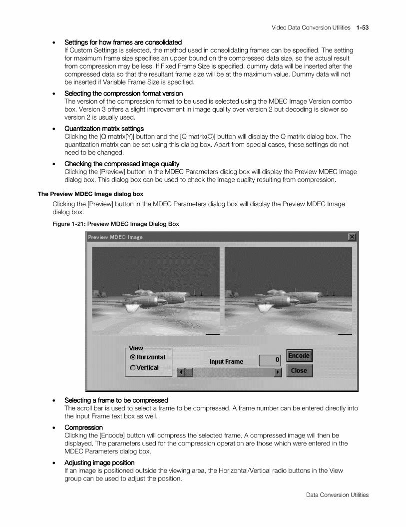
Video Data Conversion Utilities 1-53
Printed:11/19/98 4:16 PM By:SCEA Filename:final44Dataconv.doc Last saved by:SONY On:11/19/98 3:28 PM Comments: Master Copy, TechRef Release 4.3.
Data Conversion Utilities
x Settings for how frames are consolidatedSettings for how frames are consolidatedSettings for how frames are consolidatedSettings for how frames are consolidatedIf Custom Settings is selected, the method used in consolidating frames can be specified. The settingfor maximum frame size specifies an upper bound on the compressed data size, so the actual resultfrom compression may be less. If Fixed Frame Size is specified, dummy data will be inserted after thecompressed data so that the resultant frame size will be at the maximum value. Dummy data will notbe inserted if Variable Frame Size is specified.
x Selecting the compression format versionSelecting the compression format versionSelecting the compression format versionSelecting the compression format versionThe version of the compression format to be used is selected using the MDEC Image Version combobox. Version 3 offers a slight improvement in image quality over version 2 but decoding is slower soversion 2 is usually used.
x Quantization matrix settingsQuantization matrix settingsQuantization matrix settingsQuantization matrix settingsClicking the [Q matrix(Y)] button and the [Q matrix(C)] button will display the Q matrix dialog box. Thequantization matrix can be set using this dialog box. Apart from special cases, these settings do notneed to be changed.
x Checking the compressed image qualityChecking the compressed image qualityChecking the compressed image qualityChecking the compressed image qualityClicking the [Preview] button in the MDEC Parameters dialog box will display the Preview MDEC Imagedialog box. This dialog box can be used to check the image quality resulting from compression.
The Preview MDEC Image dialog box
Clicking the [Preview] button in the MDEC Parameters dialog box will display the Preview MDEC Imagedialog box.
Figure 1-21: Preview MDEC Image Dialog Box
x Selecting a frame to be compressedSelecting a frame to be compressedSelecting a frame to be compressedSelecting a frame to be compressedThe scroll bar is used to select a frame to be compressed. A frame number can be entered directly intothe Input Frame text box as well.
x CompressionCompressionCompressionCompressionClicking the [Encode] button will compress the selected frame. A compressed image will then bedisplayed. The parameters used for the compression operation are those which were entered in theMDEC Parameters dialog box.
x Adjusting image positionAdjusting image positionAdjusting image positionAdjusting image positionIf an image is positioned outside the viewing area, the Horizontal/Vertical radio buttons in the Viewgroup can be used to adjust the position.
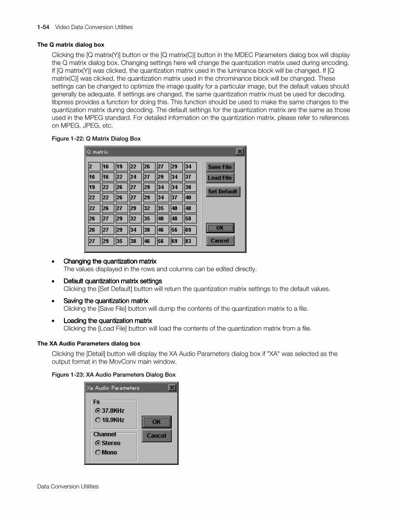
1-54 Video Data Conversion Utilities
Printed:11/19/98 4:16 PM By:SCEA Filename:final44Dataconv.doc Last saved by:SONY On:11/19/98 3:28 PM Comments: Master Copy, TechRef Release 4.3.
Data Conversion Utilities
The Q matrix dialog box
Clicking the [Q matrix(Y)] button or the [Q matrix(C)] button in the MDEC Parameters dialog box will displaythe Q matrix dialog box. Changing settings here will change the quantization matrix used during encoding.If [Q matrix(Y)] was clicked, the quantization matrix used in the luminance block will be changed. If [Qmatrix(C)] was clicked, the quantization matrix used in the chrominance block will be changed. Thesesettings can be changed to optimize the image quality for a particular image, but the default values shouldgenerally be adequate. If settings are changed, the same quantization matrix must be used for decoding.libpress provides a function for doing this. This function should be used to make the same changes to thequantization matrix during decoding. The default settings for the quantization matrix are the same as thoseused in the MPEG standard. For detailed information on the quantization matrix, please refer to referenceson MPEG, JPEG, etc.
Figure 1-22: Q Matrix Dialog Box
x Changing the quantization matrixChanging the quantization matrixChanging the quantization matrixChanging the quantization matrixThe values displayed in the rows and columns can be edited directly.
x Default quantization matrixDefault quantization matrixDefault quantization matrixDefault quantization matrix settings settings settings settingsClicking the [Set Default] button will return the quantization matrix settings to the default values.
x Saving the quantization matrixSaving the quantization matrixSaving the quantization matrixSaving the quantization matrixClicking the [Save File] button will dump the contents of the quantization matrix to a file.
x Loading the quantization matrixLoading the quantization matrixLoading the quantization matrixLoading the quantization matrixClicking the [Load File] button will load the contents of the quantization matrix from a file.
The XA Audio Parameters dialog box
Clicking the [Detail] button will display the XA Audio Parameters dialog box if "XA" was selected as theoutput format in the MovConv main window.
Figure 1-23: XA Audio Parameters Dialog Box
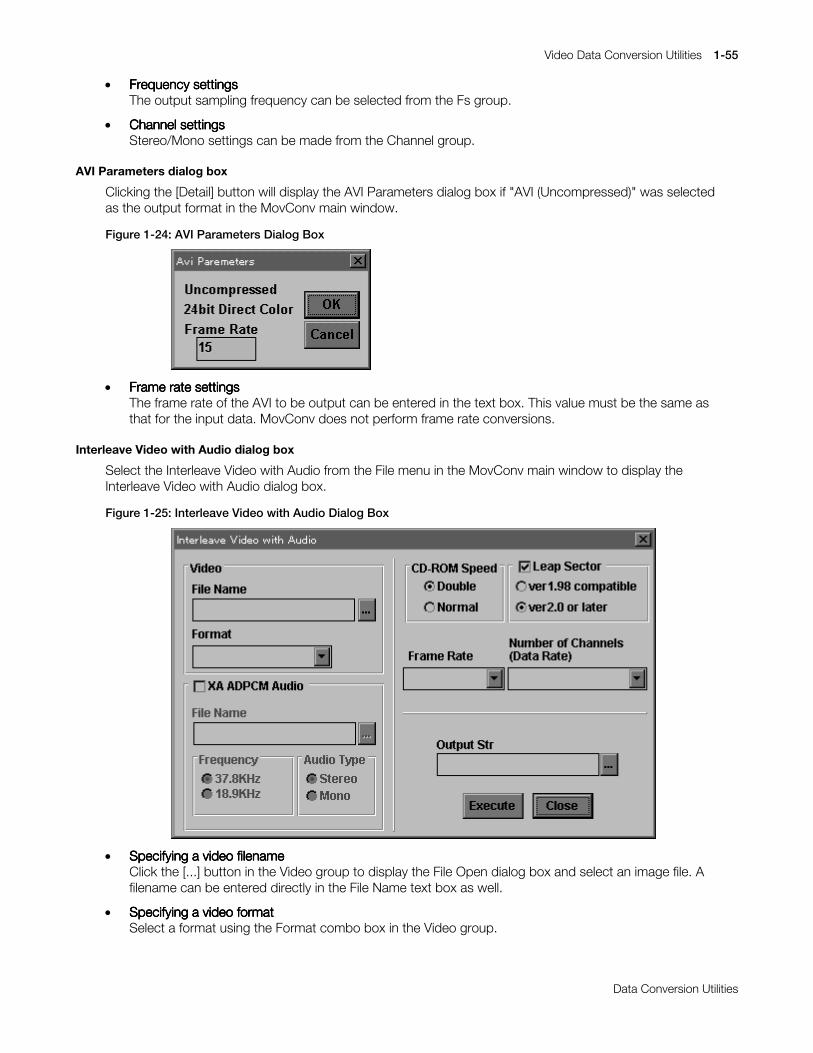
Video Data Conversion Utilities 1-55
Printed:11/19/98 4:16 PM By:SCEA Filename:final44Dataconv.doc Last saved by:SONY On:11/19/98 3:28 PM Comments: Master Copy, TechRef Release 4.3.
Data Conversion Utilities
x Frequency settingsFrequency settingsFrequency settingsFrequency settingsThe output sampling frequency can be selected from the Fs group.
x Channel settingsChannel settingsChannel settingsChannel settingsStereo/Mono settings can be made from the Channel group.
AVI Parameters dialog box
Clicking the [Detail] button will display the AVI Parameters dialog box if "AVI (Uncompressed)" was selectedas the output format in the MovConv main window.
Figure 1-24: AVI Parameters Dialog Box
x Frame rate settingsFrame rate settingsFrame rate settingsFrame rate settingsThe frame rate of the AVI to be output can be entered in the text box. This value must be the same asthat for the input data. MovConv does not perform frame rate conversions.
Interleave Video with Audio dialog box
Select the Interleave Video with Audio from the File menu in the MovConv main window to display theInterleave Video with Audio dialog box.
Figure 1-25: Interleave Video with Audio Dialog Box
x Specifying a video filenameSpecifying a video filenameSpecifying a video filenameSpecifying a video filenameClick the [...] button in the Video group to display the File Open dialog box and select an image file. Afilename can be entered directly in the File Name text box as well.
x Specifying a video formatSpecifying a video formatSpecifying a video formatSpecifying a video formatSelect a format using the Format combo box in the Video group.

1-56 Video Data Conversion Utilities
Printed:11/19/98 4:16 PM By:SCEA Filename:final44Dataconv.doc Last saved by:SONY On:11/19/98 3:28 PM Comments: Master Copy, TechRef Release 4.3.
Data Conversion Utilities
x Set Audio/No audioSet Audio/No audioSet Audio/No audioSet Audio/No audioUse the XA ADPCM Audio check box. Check the check box if video and audio are to be interleaved.Leave the box unchecked when performing a simple video format conversion with no audiointerleaving. For example, leave the box unchecked when converting a BS sequence to STR(MDEC).
x Specifying an audio filenameSpecifying an audio filenameSpecifying an audio filenameSpecifying an audio filenameIf Audio is selected, an audio filename can be entered. Click the [...] button in the XA ADPCM Audiogroup and use the File Open dialog box to select an audio file. A filename can also be entered directlyin the FileName text box.
x Specifying frequency, stereo/monoSpecifying frequency, stereo/monoSpecifying frequency, stereo/monoSpecifying frequency, stereo/monoIf Audio is selected, a frequency and stereo/mono can be selected. The values for the audio input filemust be entered. Interleaving will not be performed correctly if these settings do not match what is inthe data.
x Specifying CD-ROM speedSpecifying CD-ROM speedSpecifying CD-ROM speedSpecifying CD-ROM speedSelect Double/Normal in the CD-ROM Speed group.
x Specifying leap sectorSpecifying leap sectorSpecifying leap sectorSpecifying leap sectorssssCheck the Leap Sector check box. Refer to the MDEC Parameters dialog box settings to determine ifLeap Sector needs to be checked or not.
x Specifying the leap sectorSpecifying the leap sectorSpecifying the leap sectorSpecifying the leap sector version version version versionSelect ver 1.98 compatible if the video data to be interleaved was created with MovConv version 1.98or earlier. For data created with version 2.0 or after, select ver 2.0 or later.
x Specifying a frame rateSpecifying a frame rateSpecifying a frame rateSpecifying a frame rateSelect a frame rate from the Frame Rate combo box.
x Number of channelsNumber of channelsNumber of channelsNumber of channelsSelect the number of channels from the Number of Channels(Data Rate) combo box.
x Specifying an output fileSpecifying an output fileSpecifying an output fileSpecifying an output fileClick the [...] button from Output Str to display the File Save dialog box and specify a filename. Afilename can be entered directly into the Output Str text box as well.
x Perform interleavingPerform interleavingPerform interleavingPerform interleavingClick the [Execute] button to perform interleaving. A gauge serving as a progress indicator will bedisplayed. Click the [Cancel] button on the gauge to cancel conversion.

Video Data Conversion Utilities 1-57
Printed:11/19/98 4:16 PM By:SCEA Filename:final44Dataconv.doc Last saved by:SONY On:11/19/98 3:28 PM Comments: Master Copy, TechRef Release 4.3.
Data Conversion Utilities
The Script dialog box
The Script dialog box is displayed by selecting New Script or Open Script from the File menu in theMovConv main window.
Figure 1-26: Script Dialog Box
x Editing a scriptEditing a scriptEditing a scriptEditing a scriptThe displayed script can be edited directly.
x Saving a scriptSaving a scriptSaving a scriptSaving a scriptClick the [Save File] button to save the script to a file.
x Switching destination for message outputSwitching destination for message outputSwitching destination for message outputSwitching destination for message outputNormally, messages output due to run-time error, etc. are displayed in a dialog box. By checking theWarnings to check box and entering a filename in the text box, messages can be output to thespecified file. This prevents operation from stopping and waiting for input during execution of a script,and also provides a log of messages generated during execution.
x Executing a scriptExecuting a scriptExecuting a scriptExecuting a scriptClick the [Execute] button to execute a script.

1-58 Video Data Conversion Utilities
Printed:11/19/98 4:16 PM By:SCEA Filename:final44Dataconv.doc Last saved by:SONY On:11/19/98 3:28 PM Comments: Master Copy, TechRef Release 4.3.
Data Conversion Utilities
Available formats
MovConv can handle the following formats:
AVI (uncompressed)
The AVI Windows video format with uncompressed frame data. The compression format of AVI data canbe performed with AVI editing tools.
TIM sequences
A TIM sequence is a series of TIM-format files (the PlayStation static image format) ordered according tothe rules shown below. MovConv treats a TIM sequence as a continuous movie.
...
...xx0017.TIMxx0018.TIMxx0019.TIMxx0020.TIM......(xx is any string, the numbers do not have to be four digits long)
A TIM sequence is specified using the filename that corresponds to the initial frame. The files correspondingto the second and subsequent frames are automatically searched for in the same directory. The entiresequence of TIM files is taken to be one continuous movie.
RGB sequences
RGB is a 24-bit direct color format. Each pixel is represented by 8 bits each of red, green, and blue. Pixelsare ordered starting with the pixel in the upper left corner and ending with the pixel in the lower right cornerof the screen. There is no width or height specification in RGB format, so the width and height of the imagemust be entered separately when an RGB file is specified in MovConv. File and filename restrictions are thesame as those for TIM sequences.
YUV sequences
In the YUV(422) format, a luminance (Y) value and two chrominance (Cb, Cr) values are arranged in thefollowing manner.
Cb12, Y1, Cr12, Y2, Cb34, Y3, Cr34, Y4 ....
Each component has an 8-bit gradation. Two adjacent pixels will share the same chrominance data so thehorizontal resolution for chrominance is 1/2 of the horizontal resolution for luminance. There is no width orheight specification in YUV format, so the width and height must be entered separately when a YUV file isspecified in MovConv. File and filename restrictions are the same as those for TIM sequences.
STR(MDEC)
In the STR format, frame data is compressed for MDEC. Frame data for individual frames in STR(MDEC) isin the same format as the BS format.
BS sequences
The BS (bit stream) format is a still image format that has been compressed for MDEC. There is no width orheight specification in BS format. File and filename restrictions are the same as those for TIM sequences.
WAV
WAV is the Windows audio format. MovConv can handle 16-bit PCM WAV data with sampling frequenciesof 44KHz/22KHz/11KHz.
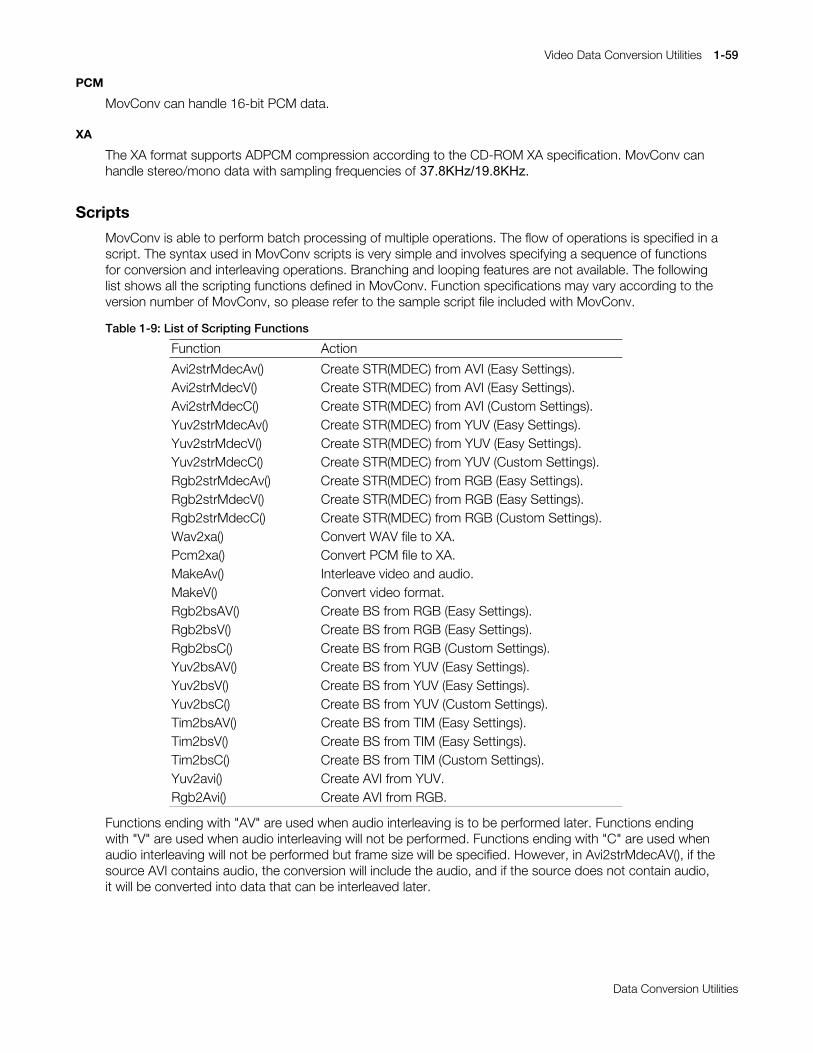
Video Data Conversion Utilities 1-59
Printed:11/19/98 4:16 PM By:SCEA Filename:final44Dataconv.doc Last saved by:SONY On:11/19/98 3:28 PM Comments: Master Copy, TechRef Release 4.3.
Data Conversion Utilities
PCM
MovConv can handle 16-bit PCM data.
XA
The XA format supports ADPCM compression according to the CD-ROM XA specification. MovConv canhandle stereo/mono data with sampling frequencies ofýêæïå.+]îìäïå.+]ï
Scripts
MovConv is able to perform batch processing of multiple operations. The flow of operations is specified in ascript. The syntax used in MovConv scripts is very simple and involves specifying a sequence of functionsfor conversion and interleaving operations. Branching and looping features are not available. The followinglist shows all the scripting functions defined in MovConv. Function specifications may vary according to theversion number of MovConv, so please refer to the sample script file included with MovConv.
Table 1-9: List of Scripting Functions
Function Action
Avi2strMdecAv() Create STR(MDEC) from AVI (Easy Settings).Avi2strMdecV() Create STR(MDEC) from AVI (Easy Settings).Avi2strMdecC() Create STR(MDEC) from AVI (Custom Settings).Yuv2strMdecAv() Create STR(MDEC) from YUV (Easy Settings).Yuv2strMdecV() Create STR(MDEC) from YUV (Easy Settings).Yuv2strMdecC() Create STR(MDEC) from YUV (Custom Settings).Rgb2strMdecAv() Create STR(MDEC) from RGB (Easy Settings).Rgb2strMdecV() Create STR(MDEC) from RGB (Easy Settings).Rgb2strMdecC() Create STR(MDEC) from RGB (Custom Settings).Wav2xa() Convert WAV file to XA.Pcm2xa() Convert PCM file to XA.MakeAv() Interleave video and audio.MakeV() Convert video format.Rgb2bsAV() Create BS from RGB (Easy Settings).Rgb2bsV() Create BS from RGB (Easy Settings).Rgb2bsC() Create BS from RGB (Custom Settings).Yuv2bsAV() Create BS from YUV (Easy Settings).Yuv2bsV() Create BS from YUV (Easy Settings).Yuv2bsC() Create BS from YUV (Custom Settings).Tim2bsAV() Create BS from TIM (Easy Settings).Tim2bsV() Create BS from TIM (Easy Settings).Tim2bsC() Create BS from TIM (Custom Settings).Yuv2avi() Create AVI from YUV.Rgb2Avi() Create AVI from RGB.
Functions ending with "AV" are used when audio interleaving is to be performed later. Functions endingwith "V" are used when audio interleaving will not be performed. Functions ending with "C" are used whenaudio interleaving will not be performed but frame size will be specified. However, in Avi2strMdecAV(), if thesource AVI contains audio, the conversion will include the audio, and if the source does not contain audio,it will be converted into data that can be interleaved later.

1-60 Video Data Conversion Utilities
Printed:11/19/98 4:16 PM By:SCEA Filename:final44Dataconv.doc Last saved by:SONY On:11/19/98 3:28 PM Comments: Master Copy, TechRef Release 4.3.
Data Conversion Utilities
Avi2strMdecAv(InputFilename, OutputFilename, CD-ROMspeed, FrameRate, NumberOfChannels, MDECversion,LeapSector, AudioFrequency, StereoMono)
>$FWLRQ@ &UHDWH#675+0'(&,#ZLWK#DXGLR#IURP#$9,+(DV\#6HWWLQJV,1
>3DUDPHWHUV@
,QSXW)LOHQDPH=# 6SHFLILHV#WKH#LQSXW#ILOHQDPH1
2XWSXW)LOHQDPH= 6SHFLILHV#WKH#RXWSXW#ILOHQDPH1
&'0520VSHHG= 6SHFLILHV#&'0520#VSHHG1#+[42[5,
)UDPH5DWH= 6SHFLILHV#WKH#IUDPH#UDWH1+43ISV24518ISV248ISV2491:ISV253ISV258ISV263ISV,
1XPEHU2I&KDQQHOV= 6SHFLILHV#WKH#QXPEHU#RI#FKDQQHOV1#+42527,
0'(&YHUVLRQ= 6SHFLILHV#0'(&#YHUVLRQ#QXPEHU1#+526,
/HDS6HFWRU= 6SHFLILHV#OHDS#VHFWRU#VHWWLQJ1#+758(2)$/6(,
$XGLR)UHTXHQF\= 6HOHFWV#;$#DXGLR#IUHTXHQF\1#+6:1;.+]24;1<.+],
6WHUHR0RQR= ,QGLFDWHV#6WHUHR20RQR1#+6WHUHR20RQR,
>([DPSOH@
$YL5VWU0GHF$Y+F=?WPS?GDWD1DYL/ &#,QSXW#ILOH#QDPHF=?WPS?RXW41VWU/ XWSXW#ILOH#QDPH[5/ &#&'0520#VSHHG48ISV/ &#)UDPH#UDWH4/ XPEHU#RI#FKDQQHOV5/ �'(&#YHUVLRQ)$/6(/ &#/HDS6HFWRU6:1;.+]/ &#)UHTXHQF\#RI#DXGLR6WHUHR WHUHR#RU#0RQR
,>
Avi2strMdecV(InputFilename, OutputFilename, CD-ROMspeed, FrameRate,NumberOfChannels, MDECversion,LeapSector)
>$FWLRQ@ &UHDWH#675+0'(&,#ZLWKRXW#DXGLR#IURP#$9,#+(DV\#6HWWLQJV,1
>3DUDPHWHUV@
,QSXW)LOHQDPH=# 6SHFLILHV#WKH#LQSXW#ILOHQDPH1
2XWSXW)LOHQDPH= 6SHFLILHV#WKH#RXWSXW#ILOHQDPH1
&'0520VSHHG= 6SHFLILHV#&'0520#VSHHG1#+[42[5,
)UDPH5DWH= 6SHFLILHV#WKH#IUDPH#UDWH1
+43ISV24518ISV248ISV2491:ISV253ISV258ISV263ISV,
1XPEHU2I&KDQQHOV= 6SHFLILHV#WKH#QXPEHU#RI#FKDQQHOV1#+42527,
0'(&YHUVLRQ= 63(&,),(6#0'(	(56,21#180%(51#+526,
/HDS6HFWRU= 6SHFLILHV#OHDS#VHFWRU#VHWWLQJ1#+758(2)$/6(,
>([DPSOH@
$YL5VWU0GHF9+F=?WPS?GDWD1DYL/ &#,QSXW#ILOH#QDPHF=?WPS?RXW51VWU/ XWSXW#ILOH#QDPH[5/ &#&'0520#VSHHG48ISV/ &#)UDPH#UDWH5/ XPEHU#RI#FKDQQHOV5/ �'(&#YHUVLRQ758( &#/HDS6HFWRU
,>

Video Data Conversion Utilities 1-61
Printed:11/19/98 4:16 PM By:SCEA Filename:final44Dataconv.doc Last saved by:SONY On:11/19/98 3:28 PM Comments: Master Copy, TechRef Release 4.3.
Data Conversion Utilities
Avi2strMdecC(InputFilename, OutputFilename, MaxFrameSize,FixedFrameSize, MDECversion)
>$FWLRQ@ &UHDWH#675+0'(&,#ZLWKRXW#DXGLR#IURP#$9,+&XVWRP#6HWWLQJV,1
>3DUDPHWHUV@
,QSXW)LOHQDPH=# 6SHFLILHV#WKH#LQSXW#ILOHQDPH1
2XWSXW)LOHQDPH= 6SHFLILHV#WKH#RXWSXW#ILOHQDPH1
0D[)UDPH6L]H= 6SHFLILHV#WKH#PD[LPXP#VL]H#RI#D#IUDPH1H[1#*43VHFWRUV*/#*53333E\WHV*
)L[HG)UDPH6L]H= 6SHFLILHV#ZKHWKHU#WKH#IUDPH#VL]H#LV#IL[HG#RUYDULDEOH1#+*)L[HG)UDPH6L]H29DULDEOH)UDPH6L]H,
0'(&YHUVLRQ= 63(&,),(6#0'(	(56,21#180%(51#+526,
>([DPSOH@
$YL5VWU0GHF&+F=?WPS?GDWD1DYL/ &#,QSXW#ILOH#QDPHF=?WPS?RXW61VWU/ XWSXW#ILOH#QDPH43VHFWRUV/ �D[LPXP#VL]H#IRU#RQH#IUDPH)L[HG)UDPH6L]H/ &#)L[HG#IUDPH#VL]H#RU#QRW5 �'(&#YHUVLRQ
,>
Yuv2strMdecAv(InputFilename, Width, Height, OutputFilename, CD-ROMspeed, FrameRate, NumberOfChannels,MDECversion, LeapSector, AudioFrequency, StereoMono)
>#$FWLRQ#@ &UHDWH#675+0'(&,#ZLWK#DXGLR#IURP#<89+(DV\#6HWWLQJV,1
>#3DUDPHWHUV#@
,QSXW)LOHQDPH=# 6SHFLILHV#WKH#LQSXW#ILOHQDPH1
:LGWK= 6SHFLILHV#WKH#ZLGWK#RI#WKH#LQSXW#LPDJH1
+HLJKW= 6SHFLILHV#WKH#KHLJKW#RI#WKH#LQSXW#LPDJH1
2XWSXW)LOHQDPH= 6SHFLILHV#WKH#RXWSXW#ILOHQDPH1
&'0520VSHHG= 6SHFLILHV#&'0520#VSHHG1#+[42[5,
)UDPH5DWH= 6SHFLILHV#WKH#IUDPH#UDWH1+43ISV24518ISV248ISV2491:ISV253ISV258ISV263ISV,
1XPEHU2I&KDQQHOV= 6SHFLILHV#WKH#QXPEHU#RI#FKDQQHOV1#+42527,
0'(&YHUVLRQ= 63(&,),(6#0'(	(56,21#180%(51#+526,
/HDS6HFWRU= 6SHFLILHV#OHDS#VHFWRU#VHWWLQJ1#+758(2)$/6(,
$XGLR)UHTXHQF\= 6(/(&76#;$#$8',2#)5(48(1&<1#+6:1;.+]24;1<.+],
6WHUHR0RQR= ,QGLFDWHV#6WHUHR20RQR1#+6WHUHR20RQR,
>#([DPSOH#@
<XY5VWU0GHF$Y+F=?WPS?GDWD33331\XY/&#,QSXW#ILOH#QDPH653/ &#:LGWK573/ &#+HLJKWF=?WPS?RXW71VWU/ XWSXW#ILOH#QDPH[5/ &#&'0520#VSHHG48ISV/ &#)UDPH#UDWH4/ XPEHU#RI#FKDQQHOV5/ �'(&#YHUVLRQ758(/ &#/HDS6HFWRU6:1;.+]/ &#)UHTXHQF\#RI#DXGLR0RQR WHUHR#RU#0RQR
,>

1-62 Video Data Conversion Utilities
Printed:11/19/98 4:16 PM By:SCEA Filename:final44Dataconv.doc Last saved by:SONY On:11/19/98 3:28 PM Comments: Master Copy, TechRef Release 4.3.
Data Conversion Utilities
Yuv2strMdecV(InputFilename, Width, Height, OutputFilename, CD-ROMspeed, FrameRate, NumberOfChannels,MDECversion, LeapSector)
>$FWLRQ@ &UHDWH#675+0'(&,#ZLWKRXW#DXGLR#IURP#<89+(DV\#6HWWLQJV,1
>3DUDPHWHUV@
,QSXW)LOHQDPH=# 6SHFLILHV#WKH#LQSXW#ILOHQDPH1
:LGWK= 6SHFLILHV#WKH#ZLGWK#RI#WKH#LQSXW#LPDJH1
+HLJKW= 6SHFLILHV#WKH#KHLJKW#RI#WKH#LQSXW#LPDJH1
2XWSXW)LOHQDPH= 6SHFLILHV#WKH#RXWSXW#ILOHQDPH1
&'0520VSHHG= 6SHFLILHV#&'0520#VSHHG1#+[42[5,
)UDPH5DWH= 6SHFLILHV#WKH#IUDPH#UDWH1+43ISV24518ISV248ISV2491:ISV253ISV258ISV263ISV,
1XPEHU2I&KDQQHOV= 6SHFLILHV#WKH#QXPEHU#RI#FKDQQHOV1#+42527,
0'(&YHUVLRQ= 63(&,),(6#0'(	(56,21#180%(51#+526,
/HDS6HFWRU= 6SHFLILHV#OHDS#VHFWRU#VHWWLQJ1#+758(2)$/6(,
>([DPSOH@
<XY5VWU0GHF9+F=?WPS?GDWD33331\XY/&#,QSXW#ILOH#QDPH653/ &#:LGWK573/ &#+HLJKWF=?WPS?RXW81VWU/# XWSXW#ILOH#QDPH[5/ &#&'0520#VSHHG48ISV/ &#)UDPH#UDWH5/ XPEHU#RI#FKDQQHOV5/ �'(&#YHUVLRQ758( &#/HDS6HFWRU
,>
Yuv2strMdecC(InputFilename, Width, Height, OutputFilename, MaxFrameSize, FixedFrameSize, MDECversion)
>$FWLRQ@ &UHDWH#675+0'(&,#ZLWKRXW#DXGLR#IURP#<89+&XVWRP#6HWWLQJV,1
>3DUDPHWHUV@
,QSXW)LOHQDPH=# 6SHFLILHV#WKH#LQSXW#ILOHQDPH1
:LGWK= 6SHFLILHV#WKH#ZLGWK#RI#WKH#LQSXW#LPDJH1
+HLJKW= 6SHFLILHV#WKH#KHLJKW#RI#WKH#LQSXW#LPDJH1
2XWSXW)LOHQDPH= 6SHFLILHV#WKH#RXWSXW#ILOHQDPH1
0D[)UDPH6L]H= 6SHFLILHV#WKH#PD[LPXP#VL]H#RI#D#IUDPH1H[1#*43VHFWRUV*/#*53333E\WHV*
)L[HG)UDPH6L]H= 6SHFLILHV#ZKHWKHU#WKH#IUDPH#VL]H#LV#IL[HG#RUYDULDEOH1#+*)L[HG)UDPH6L]H29DULDEOH)UDPH6L]H,
0'(&YHUVLRQ= 63(&,),(6#0'(	(56,21#180%(51#+526,
>([DPSOH@
<XY5VWU0GHF&+F=?WPS?GDWD33331\XY/&#,QSXW#ILOH#QDPH653/ &#:LGWK573/ &#+HLJKWF=?WPS?RXW91VWU/# XWSXW#ILOH#QDPH43VHFWRUV/ �D[LPXP#VL]H#IRU#RQH#IUDPH)L[HG)UDPH6L]H/ &#)L[HG#IUDPH#VL]H#RU#QRW5 �'(&#YHUVLRQ
,>

Video Data Conversion Utilities 1-63
Printed:11/19/98 4:16 PM By:SCEA Filename:final44Dataconv.doc Last saved by:SONY On:11/19/98 3:28 PM Comments: Master Copy, TechRef Release 4.3.
Data Conversion Utilities
Rgb2strMdecAv(InputFilename, Width, Height, OutputFilename, CD-ROMspeed, FrameRate, NumberOfChannels,MDECversion, LeapSector, AudioFrequency, StereoMono)
>#$FWLRQ#@ &UHDWH#675+0'(&,#ZLWK#DXGLR#IURP#5*%+(DV\#6HWWLQJV,1
>#3DUDPHWHUV#@
,QSXW)LOHQDPH=# 6SHFLILHV#WKH#LQSXW#ILOHQDPH1
:LGWK= 6SHFLILHV#WKH#ZLGWK#RI#WKH#LQSXW#LPDJH1
+HLJKW= 6SHFLILHV#WKH#KHLJKW#RI#WKH#LQSXW#LPDJH1
2XWSXW)LOHQDPH= 6SHFLILHV#WKH#RXWSXW#ILOHQDPH1
&'0520VSHHG= 6SHFLILHV#&'0520#VSHHG1#+[42[5,
)UDPH5DWH= 6SHFLILHV#WKH#IUDPH#UDWH1+43ISV24518ISV248ISV2491:ISV253ISV258ISV263ISV,
1XPEHU2I&KDQQHOV= 6SHFLILHV#WKH#QXPEHU#RI#FKDQQHOV1#+42527,
0'(&YHUVLRQ= 63(&,),(6#0'(	(56,21#180%(51#+526,
/HDS6HFWRU= 6SHFLILHV#OHDS#VHFWRU#VHWWLQJ1#+758(2)$/6(,
$XGLR)UHTXHQF\= 6(/(&76#;$#$8',2#)5(48(1&<1#+6:1;.+]24;1<.+],
6WHUHR0RQR= ,QGLFDWHV#6WHUHR20RQR1#+6WHUHR20RQR,
>#([DPSOH#@
5JE5VWU0GHF$Y+F=?WPS?GDWD33331UJE/&#,QSXW#ILOH#QDPH653/ &#:LGWK573/ &#+HLJKWF=?WPS?RXW:1VWU/ XWSXW#ILOH#QDPH[5/ &#&'0520#VSHHG48ISV/ &#)UDPH#UDWH4/ XPEHU#RI#FKDQQHOV5/ �'(&#YHUVLRQ758(/ &#/HDS6HFWRU6:1;.+]/ &#)UHTXHQF\#RI#DXGLR0RQR WHUHR#RU#0RQR
,>
Rgb2strMdecV(InputFilename, Width, Height, OutputFilename, CD-ROMspeed, FrameRate, NumberOfChannels,MDECversion, LeapSector)
>$FWLRQ@ &UHDWH#675+0'(&,#ZLWKRXW#DXGLR#IURP#5*%+(DV\#6HWWLQJV,1
>3DUDPHWHUV@
,QSXW)LOHQDPH=# 6SHFLILHV#WKH#LQSXW#ILOHQDPH1
:LGWK= 6SHFLILHV#WKH#ZLGWK#RI#WKH#LQSXW#LPDJH1
+HLJKW= 6SHFLILHV#WKH#KHLJKW#RI#WKH#LQSXW#LPDJH1
2XWSXW)LOHQDPH= 6SHFLILHV#WKH#RXWSXW#ILOHQDPH1
&'0520VSHHG= 6SHFLILHV#&'0520#VSHHG1#+[42[5,
)UDPH5DWH= 6SHFLILHV#WKH#IUDPH#UDWH1+43ISV24518ISV248ISV2491:ISV253ISV258ISV263ISV,
1XPEHU2I&KDQQHOV= 6SHFLILHV#WKH#QXPEHU#RI#FKDQQHOV1#+42527,
0'(&YHUVLRQ= 63(&,),(6#0'(	(56,21#180%(51#+526,
/HDS6HFWRU= 6SHFLILHV#OHDS#VHFWRU#VHWWLQJ1#+758(2)$/6(,
1-64 Video Data Conversion Utilities
Printed:11/19/98 4:16 PM By:SCEA Filename:final44Dataconv.doc Last saved by:SONY On:11/19/98 3:28 PM Comments: Master Copy, TechRef Release 4.3.
Data Conversion Utilities
>#([DPSOH#@
5JE5VWU0GHF9+F=?WPS?GDWD33331UJE/&#,QSXW#ILOH#QDPH653/ &#:LGWK573/ &#+HLJKWF=?WPS?RXW;1VWU/# XWSXW#ILOH#QDPH[5/ &#&'0520#VSHHG48ISV/ &#)UDPH#UDWH5/ XPEHU#RI#FKDQQHOV5/ �'(&#YHUVLRQ758( &#/HDS6HFWRU
,>
Rgb2strMdecC(InputFilename, Width, Height, OutputFilename, MaxFrameSize, FixedFrameSize, MDECversion)
>#$FWLRQ#@ &UHDWH#675+0'(&,#ZLWKRXW#DXGLR#IURP#5*%+&XVWRP#6HWWLQJV,1
>#3DUDPHWHUV#@
,QSXW)LOHQDPH=# 6SHFLILHV#WKH#LQSXW#ILOHQDPH1
:LGWK= 6SHFLILHV#WKH#ZLGWK#RI#WKH#LQSXW#LPDJH1
+HLJKW= 6SHFLILHV#WKH#KHLJKW#RI#WKH#LQSXW#LPDJH1
2XWSXW)LOHQDPH= 6SHFLILHV#WKH#RXWSXW#ILOHQDPH1
0D[)UDPH6L]H= 6SHFLILHV#WKH#PD[LPXP#VL]H#RI#D#IUDPH1H[1#*43VHFWRUV*/#*53333E\WHV*
)L[HG)UDPH6L]H= 6SHFLILHV#ZKHWKHU#WKH#IUDPH#VL]H#LV#IL[HG#RUYDULDEOH1#+*)L[HG)UDPH6L]H29DULDEOH)UDPH6L]H,
0'(&YHUVLRQ= 63(&,),(6#0'(	(56,21#180%(51#+526,
>#([DPSOH#@
5JE5VWU0GHF&+F=?WPS?GDWD33331UJE/&#,QSXW#ILOH#QDPH653/ &#:LGWK573/ &#+HLJKWF=?WPS?RXW<1VWU/# XWSXW#ILOH#QDPH43VHFWRUV/ �D[LPXP#VL]H#IRU#RQH#IUDPH)L[HG)UDPH6L]H/ &#)L[HG#IUDPH#VL]H#RU#QRW5 �'(&#YHUVLRQ
,>
Wav2xa(InputFilename, OutputFilename, AudioFrequency, StereoMono)
>$FWLRQ@ &RQYHUW#:$9#ILOH#WR#;$1
>3DUDPHWHUV@
,QSXW)LOHQDPH=# 6SHFLILHV#WKH#LQSXW#ILOHQDPH1
2XWSXW)LOHQDPH= 6SHFLILHV#WKH#RXWSXW#ILOHQDPH1
$XGLR)UHTXHQF\= 6(/(&76#;$#$8',2#)5(48(1&<1#+6:1;.+]24;1<.+],
6WHUHR0RQR= ,QGLFDWHV#6WHUHR20RQR1#+6WHUHR20RQR,
>([DPSOH@
:DY5[D+F=?WPS?GDWD1ZDY/ &#,QSXW#ILOH#QDPHF=?WPS?GDWD1[D/ XWSXW#ILOH#QDPH6:1;.+]/ &#)UHTXHQF\#RI#[D#DXGLR6WHUHR WHUHR#RU#0RQR#IRU#[D#DXGLR
,>
Video Data Conversion Utilities 1-65
Printed:11/19/98 4:16 PM By:SCEA Filename:final44Dataconv.doc Last saved by:SONY On:11/19/98 3:28 PM Comments: Master Copy, TechRef Release 4.3.
Data Conversion Utilities
Pcm2xa(InputFilename, PCMbitsPerSample, PCMfrequency, PCMstereoMono, OutputFilename, XAfrequency,XAstereoMono)
>$FWLRQ@ &RQYHUW#3&0#ILOH#WR#;$1
>3DUDPHWHUV@
,QSXW)LOHQDPH=# 6SHFLILHV#WKH#LQSXW#ILOHQDPH1
3&0ELWV3HU6DPSOH= 6SHFLILHV#WKH#QXPEHU#RI#VDPSOLQJ#ELWV#LQ3&0#GDWD1#+49ELW,
3&0IUHTXHQF\= 6SHFLILHV#IUHTXHQF\#RI#3&0#GDWD#+LQ#.+],1
3&0VWHUHR0RQR= 6SHFLILHV#VWHUHR2PRQR#RI#3&0#GDWD1#+6WHUHR20RQR,
2XWSXW)LOHQDPH= 6SHFLILHV#WKH#RXWSXW#ILOHQDPH1
;$IUHTXHQF\= 6(/(&76#;$#$8',2#)5(48(1&<1#+6:1;.+]24;1<.+],
;$VWHUHR0RQR= ,QGLFDWHV#6WHUHR20RQR1#+6WHUHR20RQR,
>([DPSOH@
3FP5[D+F=?WPS?GDWD1SFP/ &#,QSXW#ILOH#QDPH49ELW/ &#%LWV#3HU#6DPSOH7714.+]/ &#)UHTXHQF\#RI#3&0#DXGLR#+.+],6WHUHR/ WHUHR#RU#0RQR#IRU#3&0#DXGLRF=?WPS?GDWD1[D/ XWSXW#ILOH#QDPH6:1;.+]/ &#)UHTXHQF\#RI#[D#DXGLR6WHUHR WHUHR#RU#0RQR#IRU#[D#DXGLR
,>
MakeAv(VideoFilename, VideoFormatName, AudioFileName, OutputFilename, CD-ROMspeed, FrameRate,NumberOfChannels, LeapSector, OldLeapSector, AudioFrequency, StereoMono)
>$FWLRQ@ ,QWHUOHDYH#YLGHR#DQG#DXGLR1
>3DUDPHWHUV@
9LGHR)LOHQDPH=# 6SHFLILHV#WKH#LQSXW#ILOHQDPH1
9LGHR)RUPDW1DPH= 6SHFLILHV#WKH#YLGHR#IRUPDW#QDPH1#+VWU0'(&2EV,
$XGLR)LOH1DPH= 6SHFLILHV#WKH#DXGLR#ILOHQDPH1
2XWSXW)LOHQDPH= 6SHFLILHV#WKH#RXWSXW#ILOHQDPH1
&'0520VSHHG= 6SHFLILHV#&'0520#VSHHG1#+[42[5,
)UDPH5DWH= 6SHFLILHV#WKH#IUDPH#UDWH1+43ISV24518ISV248ISV2491:ISV253ISV258ISV263ISV,
1XPEHU2I&KDQQHOV= 6SHFLILHV#WKH#QXPEHU#RI#FKDQQHOV1#+42527,
/HDS6HFWRU= 6SHFLILHV#OHDS#VHFWRU#VHWWLQJ1#+758(2)$/6(,
2OG/HDS6HFWRU= ,QGLFDWHV#ZKHWKHU#WKH#OHDS#VHFWRU#YHUVLRQ#LV#ROG1758(#LI#WKH#YLGHR#ZDV#FUHDWHG#ZLWK#0RY&RQYYHUVLRQ#513#RU#EHIRUH1#2WKHUZLVH#)DOVH1+758(2)$/6(,
$XGLR)UHTXHQF\= 6(/(&76#;$#$8',2#)5(48(1&<1#+6:1;.+]24;1<.+],
6WHUHR0RQR= ,QGLFDWHV#6WHUHR20RQR1#+6WHUHR20RQR,

1-66 Video Data Conversion Utilities
Printed:11/19/98 4:16 PM By:SCEA Filename:final44Dataconv.doc Last saved by:SONY On:11/19/98 3:28 PM Comments: Master Copy, TechRef Release 4.3.
Data Conversion Utilities
>([DPSOH@
0DNH$Y+F=?WPS?GDWD1VWU/ 	LGHR#ILOH#QDPHVWU0'(&/ 	LGHR#IRUPDW#QDPHF=?WPS?GDWD1[D/ &#$XGLR#ILOH#QDPHF=?WPS?RXW431VWU/ XWSXW#ILOH#QDPH#+DXGLR#)#YLGHR,[5/ &#&'0520#VSHHG48ISV/ &#)UDPH#UDWH4/ XPEHU#RI#FKDQQHOV)$/6(/ &#/HDS6HFWRU)$/6(/ &#YHU41<;#FRPSDWLEOH#OHDS#VHFWRU6:1;.+]/ &#)UHTXHQF\#RI#DXGLR6WHUHR WHUHR#RU#0RQR
,>
MakeV(VideoFilename, VideoFormatName, OutputFilename, CD-ROMspeed, FrameRate, NumberOfChannels,LeapSector, OldLeapSector)
>$FWLRQ@ &RQYHUW#YLGHR#IRUPDW1
>3DUDPHWHUV@
9LGHR)LOHQDPH=# 6SHFLILHV#WKH#LQSXW#ILOHQDPH1
9LGHR)RUPDW1DPH= 6SHFLILHV#WKH#LPDJH#IRUPDW#QDPH1#+VWU0'(&2EV,
2XWSXW)LOHQDPH= 6SHFLILHV#WKH#RXWSXW#ILOHQDPH1
&'0520VSHHG= 6SHFLILHV#&'0520#VSHHG1#+[42[5,
)UDPH5DWH= 6SHFLILHV#WKH#IUDPH#UDWH1+43ISV24518ISV248ISV2491:ISV253ISV258ISV263ISV,
1XPEHU2I&KDQQHOV= 6SHFLILHV#WKH#QXPEHU#RI#FKDQQHOV1#+42527,
/HDS6HFWRU= 6SHFLILHV#OHDS#VHFWRU#VHWWLQJ1#+758(2)$/6(,
2OG/HDS6HFWRU= ,QGLFDWHV#ZKHWKHU#WKH#OHDS#VHFWRU#YHUVLRQ#LV#ROG1758(#LI#WKH#YLGHR#ZDV#FUHDWHG#ZLWK#0RY&RQYYHUVLRQ#513#RU#EHIRUH1#2WKHUZLVH#)DOVH1+758(2)$/6(,
>([DPSOH@
0DNH9+F=?WPS?GDWD1VWU/ 	LGHR#ILOH#QDPHVWU0'(&/ 	LGHR#IRUPDW#QDPHF=?WPS?RXW441VWU/ XWSXW#ILOH#QDPH#+YLGHR,[5/ &#&'0520#VSHHG48ISV/ &#)UDPH#UDWH4/ XPEHU#RI#FKDQQHOV758(/ &#/HDS6HFWRU)$/6( &#YHU41<;#FRPSDWLEOH#OHDS#VHFWRU
,>
Restrictions
x MovConv only handles 16-bit WAV and PCM audio data.x Previewing must be performed on displays with a bit depth of 16-bits or greater.
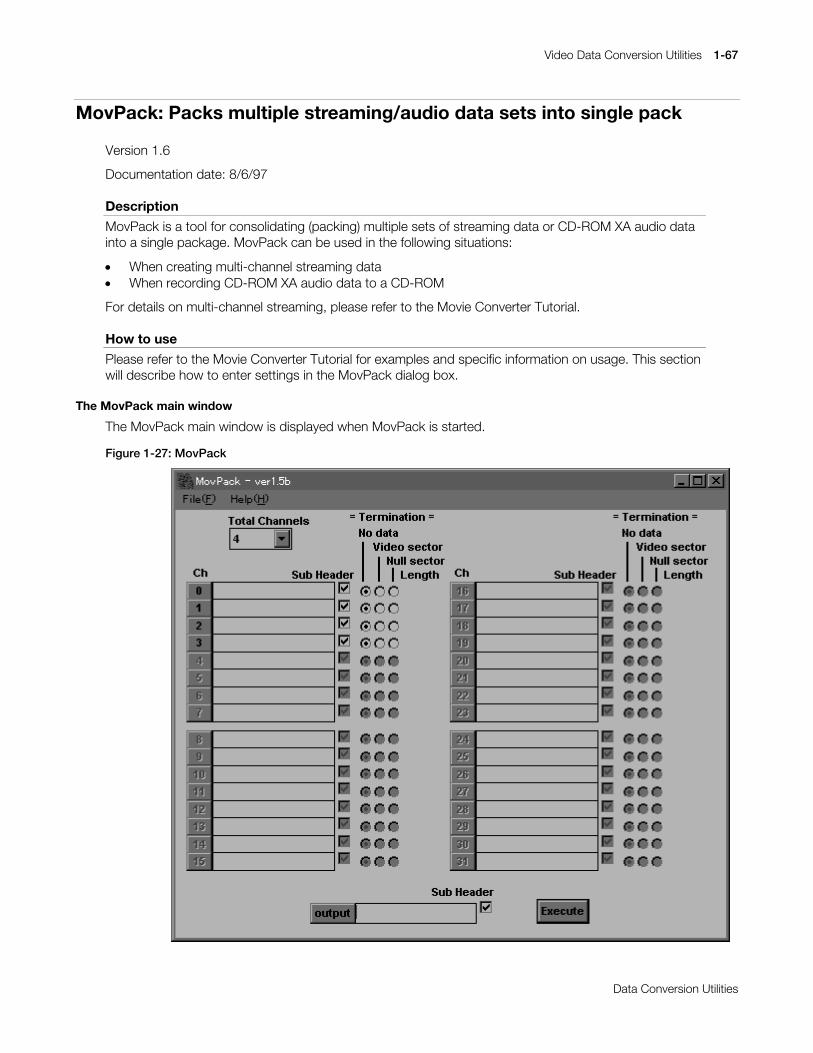
Video Data Conversion Utilities 1-67
Printed:11/19/98 4:16 PM By:SCEA Filename:final44Dataconv.doc Last saved by:SONY On:11/19/98 3:28 PM Comments: Master Copy, TechRef Release 4.3.
Data Conversion Utilities
MovPack: Packs multiple streaming/audio data sets into single pack
Version 1.6
Documentation date: 8/6/97
Description
MovPack is a tool for consolidating (packing) multiple sets of streaming data or CD-ROM XA audio datainto a single package. MovPack can be used in the following situations:
x When creating multi-channel streaming datax When recording CD-ROM XA audio data to a CD-ROM
For details on multi-channel streaming, please refer to the Movie Converter Tutorial.
How to use
Please refer to the Movie Converter Tutorial for examples and specific information on usage. This sectionwill describe how to enter settings in the MovPack dialog box.
The MovPack main window
The MovPack main window is displayed when MovPack is started.
Figure 1-27: MovPack
1-68 Video Data Conversion Utilities
Printed:11/19/98 4:16 PM By:SCEA Filename:final44Dataconv.doc Last saved by:SONY On:11/19/98 3:28 PM Comments: Master Copy, TechRef Release 4.3.
Data Conversion Utilities
x Specifying the total number of channelsSpecifying the total number of channelsSpecifying the total number of channelsSpecifying the total number of channelsThe number of total channels is entered in the Total Channels combo box. The table below shows thesettings that are entered if the data to be interleaved is XA audio data.
Table 1-10: Settings for the total number of channels in XA audio data
Playback speed Sampling frequency Stereo/Mono Total number of channels
2 X speed 37.8KHz Stereo 82 X speed 37.8KHz Mono 162 X speed 18.9KHz Stereo 162 X speed 18.9KHz Mono 321 X speed 37.8KHz Stereo 41 X speed 37.8KHz Mono 81 X speed 18.9KHz Stereo 81 X speed 18.9KHz Mono 16
The XA data output from MovConv will not play back properly if recorded directly to the CD-ROM. Forcorrect playback, the data must be interleaved according to the number of channels, as shown in thetable.
x Specifying the input filenameSpecifying the input filenameSpecifying the input filenameSpecifying the input filenameFor each channel, an input filename must be specified. Clicking on a channel button will open up a FileOpen dialog box. Select an input file here and click the "OK" button. A filename can also be entereddirectly in the text box. If the number of files to be interleaved is less than the total number of channels,the unused entries can be left blank. If no filename is specified, the channel will be left empty. For multi-channel streaming data, select STR(MDEC) for the input files. For audio data, select XA for the inputfiles.
x Setting input data sub header flagsSetting input data sub header flagsSetting input data sub header flagsSetting input data sub header flagsA subheader flag is set for channels for which files are specified. Check the Sub Header check box ifthe input data is streaming audio data or audio data. Leave the box unchecked if the streaming data isimage-only.
x Specifying termination dataSpecifying termination dataSpecifying termination dataSpecifying termination dataTermination data to be added to the end of the channel data is specified. Normally, "No data" shouldbe selected. Selecting "Video sector" will add empty video sector data at the end of the channel data.This setting can be made if, for example, audio data needs to be padded. By adding video sectors tothe end of audio data, the end of audio data can be detected by testing for video sector reads duringplayback. If "Null sector" is selected, null sectors will be added to the end of the channel data. Thissetting can be made if a gap needs to be added at the end of the data. If Video sectors or Null sectorsare specified for the termination data, the length in sectors must also be entered.
x Specifying an output filenameSpecifying an output filenameSpecifying an output filenameSpecifying an output filenameClicking the [output] button will open up a File Save dialog box. Select the output filename here andclick the [OK] button. A filename can also be entered directly in the text box.
x Specifying an output data sub header flagSpecifying an output data sub header flagSpecifying an output data sub header flagSpecifying an output data sub header flagCheck the Sub Header check box if the output data is to be streaming data with audio, or audio data.Leave the check box unchecked if the streaming data is image-only.
x InterleavingInterleavingInterleavingInterleavingClick the [Execute] button to begin interleaving.

Printed:11/19/98 4:16 PM By:SCEA Filename:final44Dataconv.doc Last saved by:SONY On:11/19/98 3:28 PM Comments: Master Copy, TechRef Release 4.3.
Data Conversion Utilities
Chapter 2:3D Graphic Conversion Utilities

2-2 3D Graphic Conversion Utilities
Printed:11/19/98 4:16 PM By:SCEA Filename:final44Dataconv.doc Last saved by:SONY On:11/19/98 3:28 PM Comments: Master Copy, TechRef Release 4.3.
Data Conversion Utilities
3D Graphic Conversion Utilities 2-3
Printed:11/19/98 4:16 PM By:SCEA Filename:final44Dataconv.doc Last saved by:SONY On:11/19/98 3:28 PM Comments: Master Copy, TechRef Release 4.3.
Data Conversion Utilities
DXF2RSD: Converts DXF to RSD
Version 2.81
Documentation date: 4/25/96
Description
This software converts the DXF file into the PlayStation 3D model data format (RSD).
How to use
DXF2RSD [options] DXF-files...
Input of a DXF file with the argument creates 4 files shown below.
x File-related information file (*.RSD)x Polygon information file (*.PLY)x Material information file (*.MAT)x Group information file (*.GRP)
These 4 files are put together into one and called "RSD" or "RSD data". The wildcard is available for theargument. You can input and convert multiple files at a time. Omission of ".DXF" of the filename is allowed.
Options
-o output-file Specify an output RSD name. The extension is removed. The default creates afilename identical with the input filename, except the extension which is removed.
-col r g b Specify a color of the whole model with R, G and B (0-255, respectively). Thedefault is the gray (200 200 200).
-cf color-file Specify a color table file.
-cl Outputs a list of undefined colors to a standard output. This sorts polygons of thesame color and outputs them to a MAT file. The default is OFF. (Refer toexample 2.)
-info Shows information about the input DXF file. This lets you know the approximatesize and number of polygons. No conversion is executed.
-max n-poly Set the maximum number of polygons which can be converted. The default is10000.
quad or -quad1 Triangulates no 4-vertex 3DFACE. This allows reduction of the number ofpolygons of the whole model. The default is OFF.
-quad2 (threshold) Synthesizes 2 adjacent triangles into one quadrangle. When an argument isdesignated, the movement of the direction (normal vector) of the two triangles canbe set by the angle and triangles below that angle are synthesized. When theargument is 0.0 synthesis takes place only when it has the same normal vector,and when the argument is 10.0, a differential of up to 10 degrees is acceptable.Designate the fractions between 0.0 and 90.0. The default is 1.0. (Refer toexample 4).
-quad3 Converts the triangle into the quadrangle whose third and fourth vertices are equalto each other. This allows any triangle to turn to a quadrangle.
-s or -g Executes the smooth (Gouraud) shading. The Default is OFF.
-e distance Regards all vertices which exist in a sphere having a radius of distance given withthe argument as the same. This allows reduction of the numbers of vertices andpolygons. Distance calculation is executed after scale-up or scale-down with the -sc option.
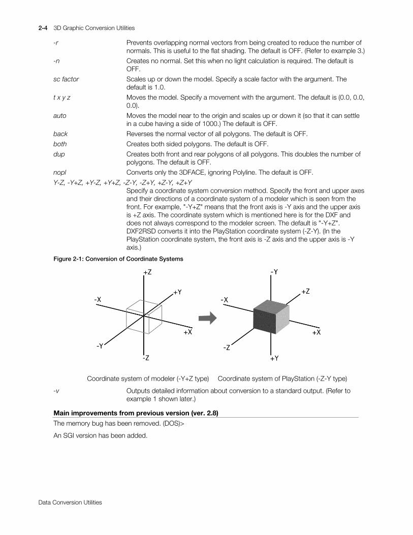
2-4 3D Graphic Conversion Utilities
Printed:11/19/98 4:16 PM By:SCEA Filename:final44Dataconv.doc Last saved by:SONY On:11/19/98 3:28 PM Comments: Master Copy, TechRef Release 4.3.
Data Conversion Utilities
-r Prevents overlapping normal vectors from being created to reduce the number ofnormals. This is useful to the flat shading. The default is OFF. (Refer to example 3.)
-n Creates no normal. Set this when no light calculation is required. The default isOFF.
sc factor Scales up or down the model. Specify a scale factor with the argument. Thedefault is 1.0.
t x y z Moves the model. Specify a movement with the argument. The default is (0.0, 0.0,0.0).
auto Moves the model near to the origin and scales up or down it (so that it can settlein a cube having a side of 1000.) The default is OFF.
back Reverses the normal vector of all polygons. The default is OFF.
both Creates both sided polygons. The default is OFF.
dup Creates both front and rear polygons of all polygons. This doubles the number ofpolygons. The default is OFF.
nopl Converts only the 3DFACE, ignoring Polyline. The default is OFF.
Y-Z, -Y+Z, +Y-Z, +Y+Z, -Z-Y, -Z+Y, +Z-Y, +Z+YSpecify a coordinate system conversion method. Specify the front and upper axesand their directions of a coordinate system of a modeler which is seen from thefront. For example, "-Y+Z" means that the front axis is -Y axis and the upper axisis +Z axis. The coordinate system which is mentioned here is for the DXF anddoes not always correspond to the modeler screen. The default is "-Y+Z".DXF2RSD converts it into the PlayStation coordinate system (-Z-Y). (In thePlayStation coordinate system, the front axis is -Z axis and the upper axis is -Yaxis.)
Figure 2-1: Conversion of Coordinate Systems
Coordinate system of modeler (-Y+Z type) Coordinate system of PlayStation (-Z-Y type)
-v Outputs detailed information about conversion to a standard output. (Refer toexample 1 shown later.)
Main improvements from previous version (ver. 2.8)
The memory bug has been removed. (DOS)>
An SGI version has been added.
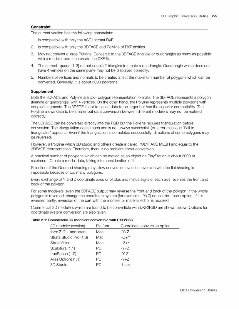
3D Graphic Conversion Utilities 2-5
Printed:11/19/98 4:16 PM By:SCEA Filename:final44Dataconv.doc Last saved by:SONY On:11/19/98 3:28 PM Comments: Master Copy, TechRef Release 4.3.
Data Conversion Utilities
Constraint
The current version has the following constraints:
1. Is compatible with only the ASCII format DXF.
2. Is compatible with only the 3DFACE and Polyline of DXF entities.
3. May not convert a large Polyline. Convert it to the 3DFACE (triangle or quadrangle) as many as possiblewith a modeler and then create the DXF file.
4. The current -quads [1-3] do not couple 2 triangles to create a quadrangle. Quadrangle which does nothave 4 vertices on the same plane may not be displayed correctly.
5. Numbers of vertices and normals to be created affect the maximum number of polygons which can beconverted. Generally, it is about 5000 polygons.
Supplement
Both the 3DFACE and Polyline are DXF polygon representation formats. The 3DFACE represents a polygon(triangle or quadrangle) with 4 vertices. On the other hand, the Polyline represents multiple polygons withcoupled segments. The 3DFCE is apt to cause data to be larger but has the superior compatibility. ThePolyline allows data to be smaller but data conversion between different modelers may not be realizedcorrectly.
The 3DFACE can be converted directly into the RSD but the Polyline requires triangulation beforeconversion. The triangulation costs much and is not always successful. (An error message "Fail totriangulate!" appears.) Even if the triangulation is completed successfully, directions of some polygons maybe reversed.
However, a Polyline which 3D studio and others create is called POLYFACE MESH and equal to the3DFACE representation. Therefore, there is no problem about conversion.
A practical number of polygons which can be moved as an object on PlayStation is about 2000 atmaximum. Create a model data, taking into consideration of it.
Selection of the Gouraud shading may allow conversion even if conversion with the flat shading isimpossible because of too many polygons.
Every exchange of Y and Z coordinate axes or of plus and minus signs of each axis reverses the front andback of the polygon.
For some modelers, even the 3DFACE output may reverse the front and back of the polygon. If the wholepolygon is reversed, change the coordinate system (for example, +Y+Z) or use the - back option. If it isreversed partly, reversion of the part with the modeler or material editor is required.
Commercial 3D modelers which are found to be convertible with DXF2RSD are shown below. Options forcoordinate system conversion are also given.
Table 2-1: Commercial 3D modelers convertible with DXF2RSD
3D modeler (version) Platform Coordinate conversion option
form Z (2.1 and later) Mac -Y+ZStrata Studio Pro (1.0) Mac +Z+YStrataVision Mac +Z+YSculptura (1.1) PC -Y+ZtrueSpace (1.0) PC -Y-ZAlias Upfront (1.1) PC -Y+Z3D Studio PC -back

2-6 3D Graphic Conversion Utilities
Printed:11/19/98 4:16 PM By:SCEA Filename:final44Dataconv.doc Last saved by:SONY On:11/19/98 3:28 PM Comments: Master Copy, TechRef Release 4.3.
Data Conversion Utilities
Commercial 3D modelers which are found to be unconvertible now are as follows.
Table 2-2: Currently unconvertible commercial 3D modelers
MacroModel (1.5) PCShadeIII (1.0) Mac
The sufficient condition for "To be convertible" is that it can output the 3DFACE DXF. Some are convertibleeven if they do not satisfy the condition. Moreover, some which cannot be converted directly may becomeconvertible when you read in and save the DXF once with another modeler.
This software creates a RSD without normal, regarding that the -n option is specified unless a too largedata allows creation of all normals.
The -r option is invalid in the Gouraud shading. You cannot use the -r option in the normal MIMe animationbecause the number and order of normals are changed if the -r option is specified.
When synthesizing two triangles into a quadrangle in -quad2 Z Sort may occur.
When the two triangles designated and synthesized in -quad2 have each been specified as different colorsby the modeler and output as DXF, that section alone can invalidate -quad2. In such cases, alsosimultaneously set the -cl option as with dxf2rsd -quad2 -cl.
Examples
Example 1: Output when the -v option is used&=!#';)556'#0Y#0DXWR#.=.<#0TXDG#0V#)22
,QSXW#';)#ILOH=#)221G[I input DXF File name>';)@#6,=(####=#73563#OLQHV number of lines in DXF####9(57(;####=#7653 number of vertices in DXF####32/<*21###=#479;#+HVWLPDWH, estimated number of polygons################60SRO\#######=#46:9# (content) triangular configurations 1376################70SRO\#######=###65 quadrilateral configurations 32################+<?,0SRO\####=####5 configurations of decagon or greater 2################SRO\OLQHV####=####5#+PD[#VL]H 65, polyline 2 (32 vertices)####5$1*(###[#=####041348#111###.31:;8 minimum and maximum value of each axis############\#=####051866#111###.31:9; Y,Z#axes are converted to PlayStation############]#=####041494#111##.31958 as required####6&$/(#####=##6351;:3 scaling factor####029(######=#+G[/G\/G], +671:;;/59:1588/;4153:, movement####0$7(5,$/##=####3 number of colored polygons>56'@#9(57(;##=##:<9 number of vertices after conversion####32/<*21###=#479; number of polygons after conversion################WULDQJOHV####=#4769# (content) triangular configurations 1436################TXDGUDQJOHV##=###65 quadrilateral configurations 32####5$1*(###[#=##05:517::#111#.5:517:: resizing minimum and maximum############\#=##08331333#111#.8331333 value of each axis after move############]#=##05:31843#111#.5:31843####0$7(5,$/##=######3 number of polygons with material####1250$/####=####:<9 number of normal lines2XWSXW#ILOHV##=#)221>UVG/#SO\/#PDW/#JUS@ output file name
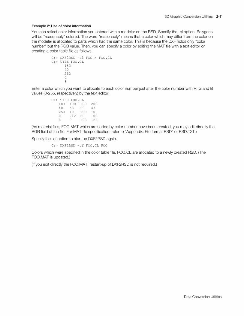
3D Graphic Conversion Utilities 2-7
Printed:11/19/98 4:16 PM By:SCEA Filename:final44Dataconv.doc Last saved by:SONY On:11/19/98 3:28 PM Comments: Master Copy, TechRef Release 4.3.
Data Conversion Utilities
Example 2: Use of color information
You can reflect color information you entered with a modeler on the RSD. Specify the -cl option. Polygonswill be "reasonably" colored. The word "reasonably" means that a color which may differ from the color onthe modeler is allocated to parts which had the same color. This is because the DXF holds only "colornumber" but the RGB value. Then, you can specify a color by editing the MAT file with a text editor orcreating a color table file as follows.
&=!#';)556'#0FO#)22#!#)221&/&=!#7<3(#)221&/######4;6######73######586######3######;
Enter a color which you want to allocate to each color number just after the color number with R, G and Bvalues (0-255, respectively) by the text editor.
&=!#7<3(#)221&/4;6##433##433##53373###8;###53###76586##43###433##433####545##53###433;####3####45;##459
(As material files, FOO.MAT which are sorted by color number have been created, you may edit directly theRGB field of the file. For MAT file specification, refer to "Appendix: File format RSD" or RSD.TXT.)
Specify the -cf option to start up DXF2RSD again.
&=!#';)556'#0FI#)221&/#)22
Colors which were specified in the color table file, FOO.CL are allocated to a newly created RSD. (TheFOO.MAT is updated.)
(If you edit directly the FOO.MAT, restart-up of DXF2RSD is not required.)
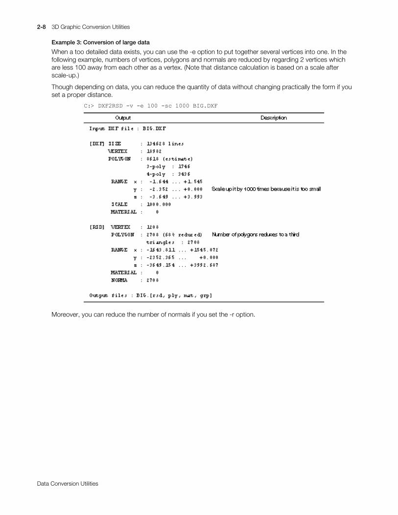
2-8 3D Graphic Conversion Utilities
Printed:11/19/98 4:16 PM By:SCEA Filename:final44Dataconv.doc Last saved by:SONY On:11/19/98 3:28 PM Comments: Master Copy, TechRef Release 4.3.
Data Conversion Utilities
Example 3: Conversion of large data
When a too detailed data exists, you can use the -e option to put together several vertices into one. In thefollowing example, numbers of vertices, polygons and normals are reduced by regarding 2 vertices whichare less 100 away from each other as a vertex. (Note that distance calculation is based on a scale afterscale-up.)
Though depending on data, you can reduce the quantity of data without changing practically the form if youset a proper distance.
&=!#';)556'#0Y#0H#433#0VF#4333#%,*1';)
Moreover, you can reduce the number of normals if you set the -r option.

3D Graphic Conversion Utilities 2-9
Printed:11/19/98 4:16 PM By:SCEA Filename:final44Dataconv.doc Last saved by:SONY On:11/19/98 3:28 PM Comments: Master Copy, TechRef Release 4.3.
Data Conversion Utilities
Example 4: Quadrangle synthesis
Two adjoining triangles can be synthesized into a quadrangle when setting the -quad2 option. In thefollowing example, by converting an angle of less than 5 degrees between the two triangles into aquadrangle, the number of polygons is reduced by almost half.
!';)556'#09#048$'5#813#($57+
,QSXW#';)#ILOH =#HDUWK1G[I>';)@#6,=( =#;;48;#OLQHV9(57(; =#;;4432/<*21 =#5<6:#+(VWLPDWH,
60SRO\ =#5<6: ?0RULJLQDOO\#5<6:#WULDQJOHV5$1*( [ =#071333#111 .61<;9
\ =#061<<:#111 .61<<:] =#071333#111 .71333
0$7(5,$/= 3
>56'@#9(57(; =#556432/<*21 =#49;9 ?05835#WULDQJOHV#DUH#V\QWKHVL]HG
WULDQJOHV =#76 %HFDPH#4584#TXDGUDQJOHVTXDGUDQJOHV =#4584 7RWDO#RI#49;9#SRO\JRQV
0$7(5,$/=#31250$/=#49;9#+TXDG5?71<;:3,
2XWSXW#ILOHV =#HDUWK1#>UVG/SO\/PDW/JUS@
The “4.9870” in NORMAL: 1686 (quad2 < 4.9870) in the middle of the figure actually refers to the largestconverted angle within the approved angles (in this case 5.0). Therefore, when “-quad2 4.986” is specifiedand executed for a second time, the number of synthesized quadrangles decreases slightly.
2-10 3D Graphic Conversion Utilities
Printed:11/19/98 4:16 PM By:SCEA Filename:final44Dataconv.doc Last saved by:SONY On:11/19/98 3:28 PM Comments: Master Copy, TechRef Release 4.3.
Data Conversion Utilities
DXF2RSDW: Converts DXF to RSD (Windows version)
Version 1.20
Documentation date: 10/16/95
Description
DXF2RSDW.EXE is a Windows application which allows you to convert the DXF format file which variousmodelers output into the PlayStation RSD format. This utility has the same capabilities as the dxf2rsdcommand line version. Execute it by double clicking on the icon registered in either the file manager orprogram manager. Since dxf2rsdw help can be displayed in the help menu, please refer to this for details.
Options
None
Notes
This current version is the command line version of dxf2rsd with GUI added. As a result, the restrictions,etc. which are present in dxf2rsd are also present in dxf2rsdw.
Messages such as ‘now converting’, ‘conversion complete’, etc. are displayed in the status bar located inthe lowest section of the application window. When conversion cannot be carried out properly, pleasecheck the message in the status bar. Ways of dealing with error messages are explained in the commandline version of the dxf2rsd, so by adjusting the parameters based on that information, conversion is madepossible.
Changes in version 1.05
Undefined color files can now be output correctly.
The maximum number of polygons which can be handled has been greatly increased. Along with this, thedefault for the maximum number of polygons has been changed from 2500 to 10000.
Changes in version 1.10
The user interface has been changed. For details on this, please refer to the on-line help (dxf2rsdw.hlp).
Changes in version 1.20
The ‘synthesized square’ added in dxf2rsd ver2.8 as a function to handle the quad2 option has beenadded to the ‘polygon shapes’ selections.
When the ‘undefined color display’ option is selected, a color coded group is created and written to theGRP file.

3D Graphic Conversion Utilities 2-11
Printed:11/19/98 4:16 PM By:SCEA Filename:final44Dataconv.doc Last saved by:SONY On:11/19/98 3:28 PM Comments: Master Copy, TechRef Release 4.3.
Data Conversion Utilities
How to use
Selection of a DXF file with "Open..." option of the "File" menu lets you access the Parameter Settingwindow. Change properly parameter values and then press the "Convert..." button or select "Give name tosave..." option from the filename. The File Save dialog pops up. Entering a post-conversion filename startsformat conversion.
You can drag an input file from the File manager to drop it in the DXF2RSDW.EXT window instead of usingthe "Open..." command.
Figure 2-2: Information Dialog
x Explanation of Parameter Setting window settingsExplanation of Parameter Setting window settingsExplanation of Parameter Setting window settingsExplanation of Parameter Setting window settingsOptions corresponding to DXF2RSD.EXE of the Commandline version are also mentioned.
x Color of the wholeColor of the wholeColor of the wholeColor of the wholeSpecify a color of the whole model with R, G and B values (0-255, respectively). This corresponds tothe -col r g b option of the Commandline version.
x Model locationModel locationModel locationModel locationMoves the model. Specify a movement. This corresponds to the -t x y z option of the Commandlineversion.
x Maximum number of polygonsMaximum number of polygonsMaximum number of polygonsMaximum number of polygonsSet the maximum number of polygons which can be converted.
This corresponds to the -max n-poly option of the Commandline version.
x Scale factorScale factorScale factorScale factorScales up or down the model. Specify a scale factor with a real number. This corresponds to the -scfactor of the Commandline version.
x Minimum vertex distanceMinimum vertex distanceMinimum vertex distanceMinimum vertex distanceRegards all vertices which exist in a sphere having a radius of distance given here as the same. Thisallows reduction of the numbers of vertices and polygons. Distance calculation is executed after scale-up or scale-down with a scale factor. This corresponds to the -distance option of the Commandlineversion.

2-12 3D Graphic Conversion Utilities
Printed:11/19/98 4:16 PM By:SCEA Filename:final44Dataconv.doc Last saved by:SONY On:11/19/98 3:28 PM Comments: Master Copy, TechRef Release 4.3.
Data Conversion Utilities
x Coordinate systemCoordinate systemCoordinate systemCoordinate systemSpecify a coordinate system conversion method. Specify the front and upper axes and their directionsof the coordinate system which is seen from the front. For example, "-Y+Z" means that the front axis is-Y axis and the upper axis is +Z axis. The coordinate system which is mentioned here is for the DXFand does not always correspond to the modeler screen. DXF2RSD converts it into the PlayStationcoordinate system (-Z-Y). (In the PlayStation coordinate system, the front axis is -Z axis and the upperaxis is -Y axis.)
This corresponds to various coordinate system options of the Commandline version.
x Display of undefined colorsDisplay of undefined colorsDisplay of undefined colorsDisplay of undefined colorsThis corresponds to the -cl option of the Commandline version.
The default of this option differs from that of the Commandline version and is ON.
x Automatic size adjustmentAutomatic size adjustmentAutomatic size adjustmentAutomatic size adjustmentMoves the model near to the origin and scales up or down it (so that it can settle in a cube having aside of 1000.)
This corresponds to the -auto option of the Commandline version.
x PolylinePolylinePolylinePolyline ignore ignore ignore ignoreIgnores the Polyline and converts only the 3DFACE. This corresponds to the -nopl option of theCommandline version.
x Normal reductionNormal reductionNormal reductionNormal reductionPrevents overlapping normal vectors being from created to reduce the number of normals. This isparticularly useful to the flat shading. This corresponds to the -r option of the Commandline version.
x Gouraud shadingGouraud shadingGouraud shadingGouraud shadingExecutes the smooth (Gouraud) shading. This corresponds to the -s or -g option of the Commandlineversion.
x Various polygonsVarious polygonsVarious polygonsVarious polygonsThere are options shown below:
x TriangleTriangleTriangleTriangleTriangulates all polygons.
x Triangulation prohibitTriangulation prohibitTriangulation prohibitTriangulation prohibitTriangulates no 4-vertex 3 DFACE. This allows reduction of the number of polygons of the wholemodel. This corresponds to the -quad option of the Commandline version.
x QuadrangleQuadrangleQuadrangleQuadrangleConverts the triangle into the quadrangle whose third and fourth vertices are equal to each other. Thiscorresponds to the -quad3 option of the Commandline version.
x Polygon attributesPolygon attributesPolygon attributesPolygon attributesThere are options shown below:
x StandardStandardStandardStandardCreates polygons and normals according to information in the DXF file.
x Normal reverseNormal reverseNormal reverseNormal reverseReverses normal vectors of all polygons. This corresponds to the -back option of the Commandlineversion.
x Both sided polygonBoth sided polygonBoth sided polygonBoth sided polygonConverts all polygons into both sided polygons. This corresponds to the -both option of theCommandline version.
x Duplicate polygonsDuplicate polygonsDuplicate polygonsDuplicate polygonsCreates both front and rear polygons of each polygon. This corresponds to the -dup option of theCommandline version.
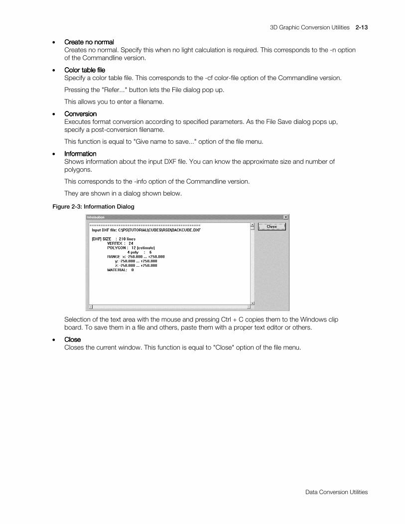
3D Graphic Conversion Utilities 2-13
Printed:11/19/98 4:16 PM By:SCEA Filename:final44Dataconv.doc Last saved by:SONY On:11/19/98 3:28 PM Comments: Master Copy, TechRef Release 4.3.
Data Conversion Utilities
x Create no normalCreate no normalCreate no normalCreate no normalCreates no normal. Specify this when no light calculation is required. This corresponds to the -n optionof the Commandline version.
x Color table fileColor table fileColor table fileColor table fileSpecify a color table file. This corresponds to the -cf color-file option of the Commandline version.
Pressing the "Refer..." button lets the File dialog pop up.
This allows you to enter a filename.
x ConversionConversionConversionConversionExecutes format conversion according to specified parameters. As the File Save dialog pops up,specify a post-conversion filename.
This function is equal to "Give name to save..." option of the file menu.
x InformationInformationInformationInformationShows information about the input DXF file. You can know the approximate size and number ofpolygons.
This corresponds to the -info option of the Commandline version.
They are shown in a dialog shown below.
Figure 2-3: Information Dialog
Selection of the text area with the mouse and pressing Ctrl + C copies them to the Windows clipboard. To save them in a file and others, paste them with a proper text editor or others.
x CloseCloseCloseCloseCloses the current window. This function is equal to "Close" option of the file menu.
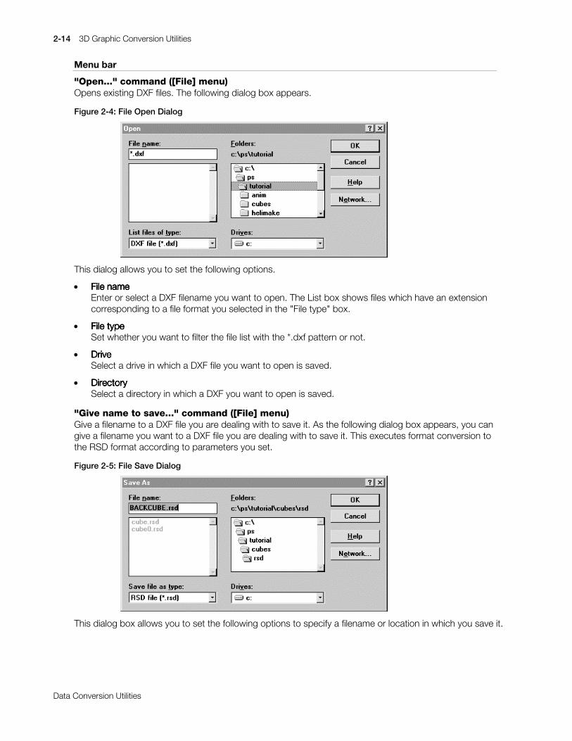
2-14 3D Graphic Conversion Utilities
Printed:11/19/98 4:16 PM By:SCEA Filename:final44Dataconv.doc Last saved by:SONY On:11/19/98 3:28 PM Comments: Master Copy, TechRef Release 4.3.
Data Conversion Utilities
Menu bar
"Open..." command ([File] menu)Opens existing DXF files. The following dialog box appears.
Figure 2-4: File Open Dialog
This dialog allows you to set the following options.
x File nameFile nameFile nameFile nameEnter or select a DXF filename you want to open. The List box shows files which have an extensioncorresponding to a file format you selected in the "File type" box.
x File typeFile typeFile typeFile typeSet whether you want to filter the file list with the *.dxf pattern or not.
x DriveDriveDriveDriveSelect a drive in which a DXF file you want to open is saved.
x DirectoryDirectoryDirectoryDirectorySelect a directory in which a DXF you want to open is saved.
"Give name to save..." command ([File] menu)Give a filename to a DXF file you are dealing with to save it. As the following dialog box appears, you cangive a filename you want to a DXF file you are dealing with to save it. This executes format conversion tothe RSD format according to parameters you set.
Figure 2-5: File Save Dialog
This dialog box allows you to set the following options to specify a filename or location in which you save it.
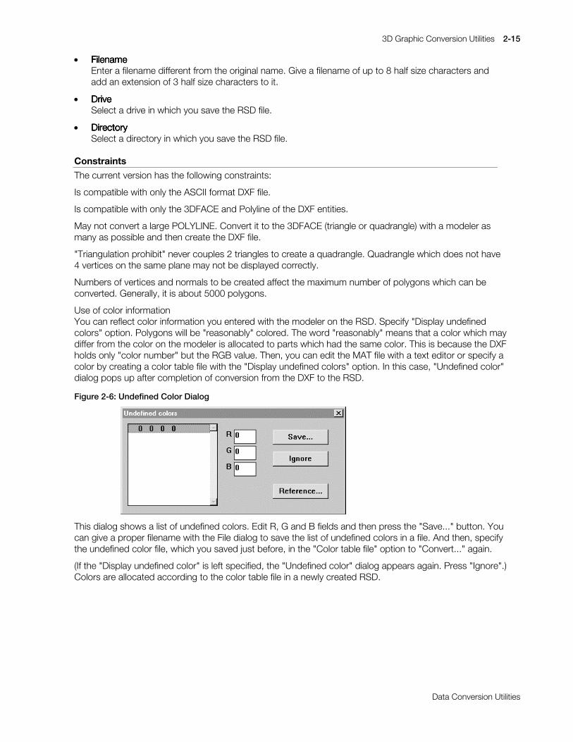
3D Graphic Conversion Utilities 2-15
Printed:11/19/98 4:16 PM By:SCEA Filename:final44Dataconv.doc Last saved by:SONY On:11/19/98 3:28 PM Comments: Master Copy, TechRef Release 4.3.
Data Conversion Utilities
x FilenameFilenameFilenameFilenameEnter a filename different from the original name. Give a filename of up to 8 half size characters andadd an extension of 3 half size characters to it.
x DriveDriveDriveDriveSelect a drive in which you save the RSD file.
x DirectoryDirectoryDirectoryDirectorySelect a directory in which you save the RSD file.
Constraints
The current version has the following constraints:
Is compatible with only the ASCII format DXF file.
Is compatible with only the 3DFACE and Polyline of the DXF entities.
May not convert a large POLYLINE. Convert it to the 3DFACE (triangle or quadrangle) with a modeler asmany as possible and then create the DXF file.
"Triangulation prohibit" never couples 2 triangles to create a quadrangle. Quadrangle which does not have4 vertices on the same plane may not be displayed correctly.
Numbers of vertices and normals to be created affect the maximum number of polygons which can beconverted. Generally, it is about 5000 polygons.
Use of color informationYou can reflect color information you entered with the modeler on the RSD. Specify "Display undefinedcolors" option. Polygons will be "reasonably" colored. The word "reasonably" means that a color which maydiffer from the color on the modeler is allocated to parts which had the same color. This is because the DXFholds only "color number" but the RGB value. Then, you can edit the MAT file with a text editor or specify acolor by creating a color table file with the "Display undefined colors" option. In this case, "Undefined color"dialog pops up after completion of conversion from the DXF to the RSD.
Figure 2-6: Undefined Color Dialog
This dialog shows a list of undefined colors. Edit R, G and B fields and then press the "Save..." button. Youcan give a proper filename with the File dialog to save the list of undefined colors in a file. And then, specifythe undefined color file, which you saved just before, in the "Color table file" option to "Convert..." again.
(If the "Display undefined color" is left specified, the "Undefined color" dialog appears again. Press "Ignore".)Colors are allocated according to the color table file in a newly created RSD.
2-16 3D Graphic Conversion Utilities
Printed:11/19/98 4:16 PM By:SCEA Filename:final44Dataconv.doc Last saved by:SONY On:11/19/98 3:28 PM Comments: Master Copy, TechRef Release 4.3.
Data Conversion Utilities
LABP: Converts Labp-formatted file to binary data
Version 1.12
Documentation date: 3/2/98
Description
Converts a labp-formatted file to binary data.
Running the C preprocessor in conjunction with the labp command permits a more intuitive way ofdescribing HMD data.
How to use
labp [options] labp-file >out-filelabp [options] <labp-file >out-file
The labp command takes a single file as input and writes the result on stdout.
An important design objective of the labp command was to reduce the complexity of handling pointerswhen HMD data is created.
The labp command can be used as an assembler for generating HMD data.
The output of the xhmd command (xhmd = HMD reverse assembler, see the xhmd document) can also beused as input for the labp command. This allows existing HMD binary data to be updated.
The input file contains a symbolic description of the data. Specific values are automatically calculated sodata can be easily added and deleted.
The following describes the syntax of the labp input file:
x Label DefinitionsA character string that starts with a letter, is followed by a sequence of letters and digits and ends witha colon (:) is considered to be a label. The first label at the beginning of the input file is assignedaddress 0.
x Numeric ValuesNumeric values can be represented as either hexadecimal or decimal integers. If a numeric valuebegins with a "0x" it is considered to be a hexadecimal number. Numeric values are expanded at thecurrent address as 32-bit values, except for cases described below under Special Operators. When anumeric value is 32 bits, the address is incremented by 4.
x Label ReferencesA character string that starts with a letter and is followed by a sequence of letters and digits isassumed to be a reference to a label. A reference to a label is replaced with the address that has beenassigned to that label.
x Operators'+', '-', '*', '/', '&', '|', and ‘~’ can be used as operators.
There is no operator precedence. Parentheses should be used to indicate precedence.
x Special OperatorsThere are 4 special unary operators: 'B', 'H', 'W', and 'M'.
B(x) places the value of x into a byte (8 bits). The address is incremented by 1.
H(x) places the value of x into a halfword (16 bits). The address is incremented by 2.
W(x) places the value of x into a word (32 bits). The address is incremented by 4. This is the samebehavior as if x alone were specified.
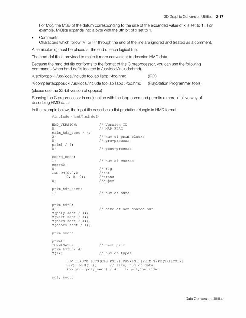
3D Graphic Conversion Utilities 2-17
Printed:11/19/98 4:16 PM By:SCEA Filename:final44Dataconv.doc Last saved by:SONY On:11/19/98 3:28 PM Comments: Master Copy, TechRef Release 4.3.
Data Conversion Utilities
For M(x), the MSB of the datum corresponding to the size of the expanded value of x is set to 1. Forexample, M(B(x)) expands into a byte with the 8th bit of x set to 1.
x CommentsCharacters which follow '//' or '#' through the end of the line are ignored and treated as a comment.
A semicolon (;) must be placed at the end of each logical line.
The hmd.def file is provided to make it more convenient to describe HMD data.
Because the hmd.def file conforms to the format of the C preprocessor, you can use the followingcommands (when hmd.def is located in /usr/local/include/hmd).
/usr/lib/cpp -I /usr/local/include foo.lab |labp >foo.hmd (IRIX)
%compiler%cpppsx -I /usr/local/include foo.lab llabp >foo.hmd (PlayStation Programmer tools)
(please use the 32-bit version of cpppsx)
Running the C preprocessor in conjunction with the labp command permits a more intuitive way ofdescribing HMD data.
In the example below, the input file describes a flat gradation triangle in HMD format.
&LQFOXGH#?KPG2KPG1GHI!
+0'B9(56,21> 22#9HUVLRQ#,'3> 22#0$3#)/$*SULPBKGUBVHFW#2#7>6> 22#QXP#RI#SULP#EORFNV3> 22#SUH0SURFHVVSULP4#2#7>3> 22#SRVW0SURFHVV
FRRUGBVHFW=4> 22#QXP#RI#FRRUGVFRRUG3=3> 22#IOJ&225'0+3/3/3 22URW
3/#3/#3,> 22WUDQV3> 22VXSHU
SULPBKGUBVHFW=4> 22#QXP#RI#KGUV
SULPBKGU3=7> 22#VL]H#RI#QRQ0VKDUHG#KGU0+SRO\BVHFW#2#7,>0+YHUWBVHFW#2#7,>0+QRUPBVHFW#2#7,>0+FRRUGBVHFW#2#7,>
SULPBVHFW=
SULP4=7(50,1$7(> 22#QH[W#SULPSULPBKGU3#2#7>0+4,> 22#QXP#RI#W\SHV
'(9B,'+6&(,_&7*+&7*B32/<,_'59+,1,,_35,0B7<3(+75,_&2/,>++5,>#0+++4,,> 22#VL]H/#QXP#RI#GDWD+SRO\3#0#SRO\BVHFW,#2#7> 22#SRO\JRQ#LQGH[
SRO\BVHFW=

2-18 3D Graphic Conversion Utilities
Printed:11/19/98 4:16 PM By:SCEA Filename:final44Dataconv.doc Last saved by:SONY On:11/19/98 3:28 PM Comments: Master Copy, TechRef Release 4.3.
Data Conversion Utilities
SRO\3=22#&RORUHG#)ODW#1R07H[WXUH#7ULDQJOH%+45;,>#%+3,>#%+3,>#%+3[63,> 22#53/#*3/#%3/#FRGH%+3,>#%+45;,>#%+3,>#%+3[63,> 22#54/#*4/#%4/#FRGH%+3,>#%+3,>#%+45;,>#%+3[63,> 22#53/#*3/#%3/#FRGH++3,>#++3,> 22#QRUP3/#YHUW3++4,>#++5,> 22#YHUW4/#YHUW5
YHUWBVHFW=69(&725+483/#483/#483,> 22#YHUW369(&725+0483/#0483/#483,> 22#YHUW469(&725+483/#0483/#483,> 22#YHUW5
QRUPBVHFW=69(&725+3/#3/#021(,> 22#QRUP3
In the example above, "HMD_VERSION", "TERMINATE", "DEV_ID", "MATRIX", "SVECTOR" and similarstrings are C preprocessor macros defined in hmd.def that will be converted into a format suitable for thelabp command.
Options
-v Print version number on stderr.
Notes
x If the syntax of the input file is invalid, labp will terminate abnormally. In this case, output is limited towhat information is available.
x It is convenient to place the "hmd.def" file in the C preprocessor include path. Please see the Clanguage user's manual for information on how to specify the include path.
x In some C language preprocessors, line feeds which are input during macro expansion can be deleted.Therefore, use of the comment symbols “/*” and “*/” which the C preprocessor deletes isrecommended rather than the labp comment symbol “//”.
x The maximum number of labels which can be used in labp is 16,384.
Changes in Version 1.02
Error processing for handling the input of incorrect data has been added.
The number of labels which can be used has increased from the 1,024 in Version 1.00 to 16,384.
Changes in Version 1.10
The bug relating to the intensity of the unary operator and operator combination has been fixed.
The built-in RotMatrix and VectorNormalS operators are now supported.
The input file line number which is output along with the error message is now output before being passedthrough the C language preprocessor.
Changes in Version 1.12
The unary operator ‘~’ was added for bit inversion. This operator is used from hmd.def 1.12 onwards.
3D Graphic Conversion Utilities 2-19
Printed:11/19/98 4:16 PM By:SCEA Filename:final44Dataconv.doc Last saved by:SONY On:11/19/98 3:28 PM Comments: Master Copy, TechRef Release 4.3.
Data Conversion Utilities
MESHCONV: Creates MSH file for RSD extension
Version 1.2
Documentation Date: 3/2/98
Description
This software creates a MSH file which is an RSD extension file. By adding this file to the RSD file, it ispossible to retain the polygon linkage information. Also, the MSH file generated is needed in order to createHMD data which includes linkage information.
How to use
meshconv [options] RSD-file
Creates an MSH file from an RSD format file. The default creates a filename identical with the inputfilename except the extension which is replaced with “.msh”.
Options
-o output-file Specify the output file name. The default creates a filename identical with the inputfilename in the current directory except the extension which is replaced with “.msh”. Thisbecomes effective when an MSH file has been specified within the RSD file.
-min X Selects the lowest linked number. The default is 2.
-max X Selects the highest linked number. The default is f.
-help, -? Displays a summary of options which can be selected and a simple usage method.
-ns Prevents the linkage of shared polygons.
Remarks
x The related files to be used must exist in the same directory. If they exist in separate directories, specifythe relative path or the absolute path.
x The MSH file to be output takes into account the information displayed within the RSD file andgenerates an MSH file. Since HMD cannot express linkage which extends over multiple matrices,make sure that the COD file is included when creating the MSH file. If the COD file is not specified, theobject will be recognized as having only one matrix.
x When the output file name already exists, the contents are overwritten. Attention must be paid as nowarning will be given.
x This program is compatible with the following RSD format versions. Be aware that no other RSD fileversions can be used.
RSD File version 3.0PLY File version 3.0MAT File version 3.0GRP File version 3.0MSH File version 1.0 (Output file)PVT File version 1.0COD File version 1.0OGP File version 1.0MOT File version 1.0
In meshconv (version1.0) the 5 RSD, PLY, MAT, COD and OGP files are read. Therefore, at the presenttime, the versions of files other than these five are not necessary. Since there is the possibility that they willbe read in the future, the latest version should be used for all.

2-20 3D Graphic Conversion Utilities
Printed:11/19/98 4:16 PM By:SCEA Filename:final44Dataconv.doc Last saved by:SONY On:11/19/98 3:28 PM Comments: Master Copy, TechRef Release 4.3.
Data Conversion Utilities
Changes in Version 1.0
First Release. (Distributed with PlayStation Runtime Library 4.0. Released on the BBS on July 2nd)
Changes in Version 1.1
The bug which caused the format of the internal function return values to be incorrect has been fixed. (Thebug caused occasional crashes and entry into endless loops)
Changes in Version 1.2
The comments which were output before the ID are no longer output.

3D Graphic Conversion Utilities 2-21
Printed:11/19/98 4:16 PM By:SCEA Filename:final44Dataconv.doc Last saved by:SONY On:11/19/98 3:28 PM Comments: Master Copy, TechRef Release 4.3.
Data Conversion Utilities
MIMEFILT: Creates MIMe difference file from TMD
Version 1.51
Documentation date: 4/1/96
Description
This software reads in multiple TMD files and creates the MIMe difference file.
How to use
MIMEFILT. [options] BASE.TMD VARIANT1.TMD VARIANT2.TMD...
Input of multiple TMD formats examines differences between the first TMD and the second and followingTMDs to collect them in a difference file.
Differences between corresponding vertex coordinates and between normal vectors can be examined. Thedefault creates only the vertex difference file (.VDF).
The wildcard is available for the argument. Omission of “.TMD” of the filename is allowed.
Options
-o output-file Specify an output filename. This filename is used for the vertex difference filename (.VDF)and normal difference filename (.NDF). The default gives a filename identical with theoriginal TMD filename except the extension which is removed.
-n Creates a normal difference file (.NDF). The default is OFF.
-v Outputs detailed information about conversion to a standard output. The default is OFF.
Main improvements from previous version (ver. 1.5)
It is now possible to use the wildcard in the argument (with DOS).
Supplement
Numbers of vertices of all argument TMD files must be equal to each other. To create each TMD file, takecare not to change the number and order of vertices. Create a basic prototype model with a 3D modelerwhich consists of sufficiently detailed polygons then move planes and vertices of the model to create adeformation model. (The number and order of vertices are not changed.) Save each model in the DXFformat and convert it into the RSD format with DXF2RSD and then apply RSDLINK to it separately to createthe TMD file.
File format
Format of the difference file created by MIMEFILT is the binary format in which blocks having the headerand difference information for each object are coupled. (The normal difference file has the same format.)
&=!#0,0(),/7#02170'#04170'#05170'
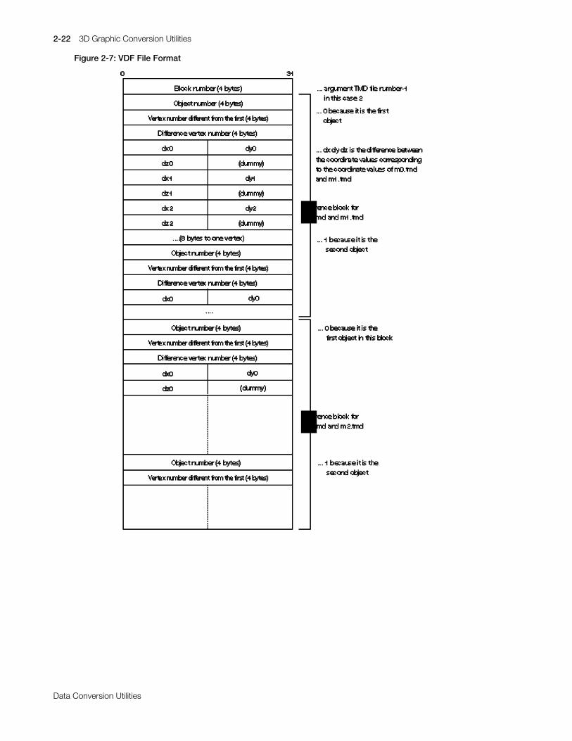
2-22 3D Graphic Conversion Utilities
Printed:11/19/98 4:16 PM By:SCEA Filename:final44Dataconv.doc Last saved by:SONY On:11/19/98 3:28 PM Comments: Master Copy, TechRef Release 4.3.
Data Conversion Utilities
Figure 2-7: VDF File Format
3D Graphic Conversion Utilities 2-23
Printed:11/19/98 4:16 PM By:SCEA Filename:final44Dataconv.doc Last saved by:SONY On:11/19/98 3:28 PM Comments: Master Copy, TechRef Release 4.3.
Data Conversion Utilities
MIMESORT: Sorts TMD Vertex Information
Version 2.1
Documentation date: 6/13/96
Description
This software reads in multiple TMD files and sorts vertex information. Use of this software before executionof MIMEFILT reduces the difference file. This lets the MIMe animation speed be higher.
How to use
MIMESORT [options] BASE.TMD VARIANT1.TMD[VARIANT2.TMD [VARIANT3.TMD...]]
This sorts vertex information in the TMD file and creates a new TMD file in order to reduce a MIMedifference file to be created by MIMEFILET. This allows reduction of calculation time for the MIMe animationrun time.
As MIMESORT changes the order of the vertex information, all files to be filtered by MIMEFILT must also besorted by MIMESORT. Sorting partly only some files with MIMESORT does not produce a correctdifference file because vertices between TMD files cannot be corresponded to each other.
The wildcard is available for the argument.
When the -m option is not used, mimesort automatically sorts the vertices according to the vertexinformation within the model file. If the number of variation model files (TMD files other than base-model)exceeds 14, however, the specified models from the 15th onward are not used for sorting. As only the first14 models are used as information for sorting, vertex information is rearranged on the models from the 15thonward. In other words, the variation model files from the 15th onward may possibly be made inefficientduring output. Use of the -m option is recommended when the number of variation models is large.
To obtain the best possible results, please refer to the remarks section.
Options
-d directory Specify an output directory in which you want to place the sorted TMD file. The default is“..\STMD”. You must create an output directory beforehand.
-v Outputs the order of vertices before and after sorting to an standard output. This allowsyou to check how the sorting was. The default outputs nothing. Meanings of outputs areas follows:
file: (vertex: a/b)file: filenamea: Number of vertices contained in the difference fileb: Total number of vertices.: Vertices which have no difference and are not contained in the difference file+: Vertices which have no difference but are contained in the difference file*: Vertices which have differences and are contained in the difference file
Supplement
Does not sort any other data than the vertex data (for example, normal data).
Does not always reduce the difference file. In order to make sure of MIMESORT’s effect, filter data bothbefore and after MIMESORT with MIMEFILT to check the size of the difference file. The smaller the size is,the more efficient the data is.
An input TMD file has to be a file which can be filtered with MIMEFILT. MIMEDORT does not deal with theTMD file which contains multiple objects.

2-24 3D Graphic Conversion Utilities
Printed:11/19/98 4:16 PM By:SCEA Filename:final44Dataconv.doc Last saved by:SONY On:11/19/98 3:28 PM Comments: Master Copy, TechRef Release 4.3.
Data Conversion Utilities
The wildcard is available for the filename. However, specify it so that the base file comes in the head of thefile. If a file which has to be a variant file is found in the base file position, an expected sorting result is notacquired. Check whether the wildcard works as it is expected or not with a message “base files=” which isgiven at execution.
Creates files just below the output directory even if a sub-directory is specified in the base or variantfilename. Therefore, never specify an input file which has the same filename in a different directory.
Never specify the current directory such as “.” to the output directory. If it is specified, an output fileoverwrites and damages the input file.
Be aware of the restriction in the number of characters in the MS-DOS command line.Data other than vertex data (such as normal data, etc.) cannot be sorted.
Notes
When handling multiple deformation model files:
The use of MIMe for key frame animations where key frames for models are arranged in time series mayoften result in an enormous number of MIMe parameters. The concurrent application of too manyparameters to a model consumes much time and memory, however. The replacement of the base modelfor key frame animations at places where only a few key frames are correlated with one another leads toefficiency enhancement.
If there are still more deformation files, use the -m option. Also use the -m option if you are not satisfiedwith the automatic vertex sort results.
Changes in version 1.1
The bug regarding the handling of a TMD file with a large PRIMITIVE section has been corrected.
Vertices are rearranged for 15 to 32 variation model files
Changes in version 1.2
The -stdin option enables the standard input of a model file name.
Changes in version 1.3
The bug whereby a primitive other than a triangle polygon could not be handled properly has beencorrected.
Changes in version 2.0
A mode (-m option) which rearranges the vertices according to the sort table designated by the user hasbeen added. Over 15 deformation model files can be handled when using this -m option,
Changes in version 2.1
The message output bug has been fixed and the output message has been standardized with the English.
3D Graphic Conversion Utilities 2-25
Printed:11/19/98 4:16 PM By:SCEA Filename:final44Dataconv.doc Last saved by:SONY On:11/19/98 3:28 PM Comments: Master Copy, TechRef Release 4.3.
Data Conversion Utilities
MKMIME: Makes MIMe for HMD
Version 1.12
Documentation date: 10/26/98
Description
Reads multiple HMD files and creates an HMD file which includes MIMeinformation.
How to use
mkmime [options] hmd0 hmd1 [hmd2...] >out-file
The mkmime command takes 2 or more HMD files, finds the differences between them and writes an HMDfile to stdout that contains the MIMe information. One file is used as the base MIMe and additional files areuse as the MIMe key. mkmime is similar to the mimefilt command which obtains difference information forTMD files. However, mkmime not only writes out differences but outputs completely formatted HMD dataas well. Differences, vertices, normals, and coordinates can all be calculated.
If no options are set, the differences of vertices and coordinates are obtained and HMD data is created asVertex-MIMe, Joint-Axes-MIMe.
Options
-v Print version number on stderr.
+vert Generate Vertex-MIMe information.When vertex information is the same in all specified HMD files, information pertaining toVertex-MIMe is not generated even if this option is specified.This is the default setting.
-vert Inhibit the generation of Vertex-MIMe information.Vertex differences are ignored within the specified HMD file.
+norm Generate Normal-MIMe information.When normal information is the same in all specified HMD files, information pertaining toNormal-MIMe is not generated even if this option is specified.
-norm Inhibit Normal-MIMe information.Normal differences are ignored within the specified HMD file.This is the default setting.
+axes Generate Joint-Axes-MIMe information.When coordinate information is the same in all specified HMD files, information pertainingto Axes MIMe is not generated even if this option is specified.When this option is specified, the -rpy option discussed below automatically becomeseffective and the output of Joint-RPY-MIMe information is suppressed.This is the default setting.
-axes Inhibit the generation of Joint-Axes-MIMe information.Coordinate differences are ignored within the specified HMD file.
+rpy Generate Joint-RPY-MIMe information.When coordinate information is the same in all specified HMD files, information pertainingto Joint-RPY-MIMe is not generated even if this option is specified.When this option is specified, the -axes option discussed above automatically becomeseffective and the output of Joint-Axes-MIMe information is suppressed.
-rpy Inhibit the generation of Joint-RPY-MIMe information.Coordinate differences are ignored within the specified HMD file.

2-26 3D Graphic Conversion Utilities
Printed:11/19/98 4:16 PM By:SCEA Filename:final44Dataconv.doc Last saved by:SONY On:11/19/98 3:28 PM Comments: Master Copy, TechRef Release 4.3.
Data Conversion Utilities
This is the default setting.
Notes
x If the contents of the input HMD files are invalid, mkmime will terminate abnormally. In this case, outputis limited to what information is available.
x All input HMD files must be the same size.
x The MIMePr section is not created. Within the output HMD, the data word which contains the MIMEIDof the MIMe primitive header and the MIMEPR PTR are set to 0.In this case, the MIMe parameter must be provided by the application program.
x MIMe information is added at the end of the HMD input file.
x When it is necessary to place data other than MIMe (e.g. image data) at the end of HMD data, and thexhmd command is used to disassemble the output HMD file, the HMD file must be restructured usinglabp after performing appropriate post editing. (xhmd and labp are described in separate documents).
Changes in Version 1.02
xý A bug which made Shared Polygon Primitives (other than those lined to post-process) unable toprocess, was fixed.
Changes in Version 1.10
xý This software is now compatible with the HMD MIMe format which was changed from PlayStationlibrary version 4.1 onwards. Please note that the HMD file created by mkmime 1.10 is not compatiblewith libraries prior to library 4.0.
Changes in Version 1.11
xý A bug that sometimes caused abnormal termination when mkmime was activated with no argumentsspecified, was fixed.
Changes in Version 1.12
xý An bug that occasionally caused an abnormal termination in assertion failed was fixed.
3D Graphic Conversion Utilities 2-27
Printed:11/19/98 4:16 PM By:SCEA Filename:final44Dataconv.doc Last saved by:SONY On:11/19/98 3:28 PM Comments: Master Copy, TechRef Release 4.3.
Data Conversion Utilities
MKTOD: Makes TOD from PRJ and HRC files
Version 1.4
Documentation date: 5/1/96
Description
This software reads in the project information (PRJ file) and hierarchy information (HRC file) to create thelayout file (TOD file).
How to use
MKTOD [options] hrc-file...
MKTOD is executed in the project directory and reads in the project file (MODEL.PRJ and OBJECT.RPJ)and the HRC file which is given with the argument to create the TOD file in the TOD directory. The TOD filehas information about the layout of multiple objects. Unless the TOD directory exists in the currentdirectory, a TOD file is created in the current directory. In both case, both project files must exist in thecurrent file.
The HRC file which is the argument must exist in the current directory (.\) or .\HRC unless a path isspecified explicitly. MKTOD searches the HRC file in this order. Omission of the extension “.HRC” isallowed.
Options
-o output-file Specify an output TOD filename. The default creates a filename identical with the argumentHRC filename in the current directory except the extension which is replaced with “.TOD”.
-tree Outputs the hierarchical structure of object to a standard output.
-v Outputs information about what is being converted to a standard output.
Changes from Version 1.3
Previously there were cases where part of the origin was not output properly, but this has now beencorrected.
An SGI version has been added.
Constraints
The current version has the following constraints:
Skips sequence blocks in the HRC file. Therefore, the TOD file which is created by MKTOD is always for aframe (that is, it is not an animation data but layout data.)
Note
Never use the parallel move (-t) or scale-up/down (-s) option of RSDLINK to create a program which usesthe TOD file outputted by a animation tool or MKTOD. Specifying the move or scale-up/down option inconversion from the RSD to the TMD causes wrong movement or size of object because the movementand scale factor for the RSD object are stored in the TOD file. Execute the move or scale-up/down with theRSD data with RSDFORM beforehand.
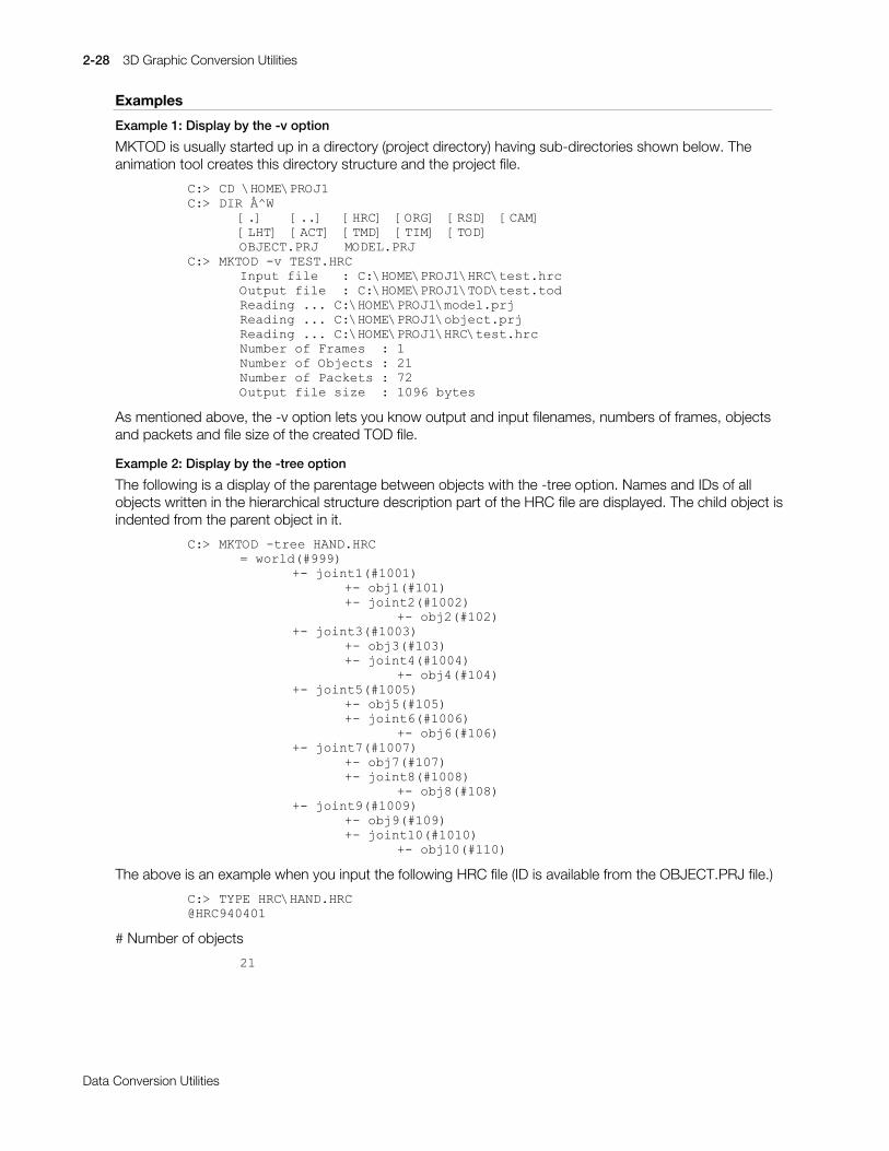
2-28 3D Graphic Conversion Utilities
Printed:11/19/98 4:16 PM By:SCEA Filename:final44Dataconv.doc Last saved by:SONY On:11/19/98 3:28 PM Comments: Master Copy, TechRef Release 4.3.
Data Conversion Utilities
Examples
Example 1: Display by the -v option
MKTOD is usually started up in a directory (project directory) having sub-directories shown below. Theanimation tool creates this directory structure and the project file.
&=!#&'#?+20(?352-4&=!#',5#cA:
>1@ >11@ >+5&@ >25*@ >56'@ >&$0@>/+7@ >$&7@ >70'@ >7,0@ >72'@2%-(&7135- 02'(/135-
&=!#0.72'#0Y#7(671+5&,QSXW#ILOH###=#&=?+20(?352-4?+5&?WHVW1KUF2XWSXW#ILOH##=#&=?+20(?352-4?72'?WHVW1WRG5HDGLQJ#111#&=?+20(?352-4?PRGHO1SUM5HDGLQJ#111#&=?+20(?352-4?REMHFW1SUM5HDGLQJ#111#&=?+20(?352-4?+5&?WHVW1KUF1XPEHU#RI#)UDPHV##=#41XPEHU#RI#2EMHFWV#=#541XPEHU#RI#3DFNHWV#=#:52XWSXW#ILOH#VL]H##=#43<9#E\WHV
As mentioned above, the -v option lets you know output and input filenames, numbers of frames, objectsand packets and file size of the created TOD file.
Example 2: Display by the -tree option
The following is a display of the parentage between objects with the -tree option. Names and IDs of allobjects written in the hierarchical structure description part of the HRC file are displayed. The child object isindented from the parent object in it.
&=!#0.72'#0WUHH#+$1'1+5& #ZRUOG+&<<<,
.0#MRLQW4+&4334,.0#REM4+&434,.0#MRLQW5+&4335,
.0#REM5+&435,.0#MRLQW6+&4336,
.0#REM6+&436,
.0#MRLQW7+&4337,.0#REM7+&437,
.0#MRLQW8+&4338,.0#REM8+&438,.0#MRLQW9+&4339,
.0#REM9+&439,.0#MRLQW:+&433:,
.0#REM:+&43:,
.0#MRLQW;+&433;,.0#REM;+&43;,
.0#MRLQW<+&433<,.0#REM<+&43<,.0#MRLQW43+&4343,
.0#REM43+&443,
The above is an example when you input the following HRC file (ID is available from the OBJECT.PRJ file.)
&=!#7<3(#+5&?+$1'1+5&#+5&<73734
# Number of objects
54
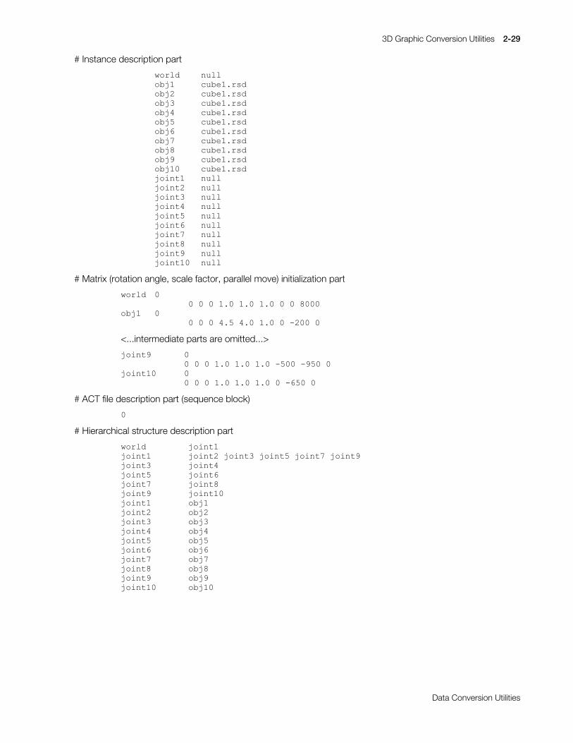
3D Graphic Conversion Utilities 2-29
Printed:11/19/98 4:16 PM By:SCEA Filename:final44Dataconv.doc Last saved by:SONY On:11/19/98 3:28 PM Comments: Master Copy, TechRef Release 4.3.
Data Conversion Utilities
# Instance description part
ZRUOG QXOOREM4 FXEH41UVGREM5 FXEH41UVGREM6 FXEH41UVGREM7 FXEH41UVGREM8 FXEH41UVGREM9 FXEH41UVGREM: FXEH41UVGREM; FXEH41UVGREM< FXEH41UVGREM43 FXEH41UVGMRLQW4 QXOOMRLQW5 QXOOMRLQW6 QXOOMRLQW7 QXOOMRLQW8 QXOOMRLQW9 QXOOMRLQW: QXOOMRLQW; QXOOMRLQW< QXOOMRLQW43 QXOO
# Matrix (rotation angle, scale factor, parallel move) initialization part
ZRUOG 33#3#3#413#413#413#3#3#;333
REM4 33#3#3#718#713#413#3#0533#3
<...intermediate parts are omitted...>
MRLQW< 33#3#3#413#413#413#0833#0<83#3
MRLQW43 33#3#3#413#413#413#3#0983#3
# ACT file description part (sequence block)
3
# Hierarchical structure description part
ZRUOG# MRLQW4MRLQW4# MRLQW5#MRLQW6#MRLQW8#MRLQW:#MRLQW<MRLQW6# MRLQW7MRLQW8# MRLQW9MRLQW:# MRLQW;MRLQW<# MRLQW43MRLQW4# REM4MRLQW5# REM5MRLQW6# REM6MRLQW7# REM7MRLQW8# REM8MRLQW9# REM9MRLQW:# REM:MRLQW;# REM;MRLQW<# REM<MRLQW43# REM43

2-30 3D Graphic Conversion Utilities
Printed:11/19/98 4:16 PM By:SCEA Filename:final44Dataconv.doc Last saved by:SONY On:11/19/98 3:28 PM Comments: Master Copy, TechRef Release 4.3.
Data Conversion Utilities
RSD2DXF: Converts RSD to DXF
Version 1.10
Documentation date: 9/1/95
Description
This software converts the RSD format file group into the DXF format. This is an MS-DOS Commandlineapplication.
How to use
RSD2DXF[options] [ARG-files...]RSD-files...
A filename of the DXF to be outputted is identical with the input RSD filename except the extension which isreplaced with “.DXF”. The wildcard is available for the argument.
Options
-o output-file Specify an output filename. The default creates a filename identical with the input filenamein the current directory except the extension which is replaced with “.DXF”. Use of thisoption is allowed only when only one RSD file is inputted.
-r Reverses the front and rear of all polygons that are contained in a DXF file to be created.
-h Shows a list of options which can be specified and an easy-to-use method.
-v Shows information about conversion.
-ARG-files Specify an argument file which describes options for RSD2DXF.EXE, input filename andothers. With this, the filename having the extension “.ARG” is constructed as the argumentfile. Use this when the command argument of above 128 bytes is required.
The line starting with “#” is regarded as comment and has no effect on execution ofRSD2DXF.EXE.
Remarks
In a coordinate system of the DXF file to be created, the right side is +X, the upper side is +Y and the rearside is +Z. It is identical with the default which DXF2RSD.EXE and DXFRSDW.EXE suppose as thecoordinate system of the DXF file. Therefore, when you read in and edit the DXF file to be created with amodeler, in order to let the model be subject to the coordinate system of the modeler, rotation of the modelis required.
Information about the normal, color and texture contained in the RSD file is discarded.
If the same output filename exists, the contents are overwritten. No warning will be given so pay attentionto it.
Even if a argument filename is written in the argument file, it is meaningless.
The wildcard is unavailable in the argument file.

3D Graphic Conversion Utilities 2-31
Printed:11/19/98 4:16 PM By:SCEA Filename:final44Dataconv.doc Last saved by:SONY On:11/19/98 3:28 PM Comments: Master Copy, TechRef Release 4.3.
Data Conversion Utilities
RSD2HMD: Converts RSD to HMD
Version 1.5
Documentation date: 3/2/98
Description
rsd2hmd converts an RSD format file into HMD format.
How to use
rsd2hmd [options] RSD-file
Converts an RSD format file to HMD format. “.hmd” is added to the input file name from which theextension has been removed to create the file name of the HMD file which will be output.
Options
-o output file Specify an output file name. The default creates a filename identical with the inputfilename in the current directory, except that the extension is changed to “hmd”.
-s X Enlarges or reduces the object using the specified scaling factor.
-help,-? Displays a list of options which can be specified and an easy-to-use method.
-bin2cl file-name Outputs the output HMD data expressed as Hexadecimal notations to thespecified file.
-ni Does not output image data to HMD.
Remarks
x The RSD file and TIM file used must exist in the same directory. If they exist in separate directories,specify the relative path or the absolute path.
x The output HMD file contains all the information displayed within the RSD file. If information which youdo not wish to include such as linkage information or COORDINATE information is present, either donot perform file specification within the RSD file or comment it out.
x When the same output file name already exists, the contents will be overwritten. Attention must bepaid as no warning will be given.
x This program is compatible with the following RSD format versions. Be aware that no other RSD fileversions can be used.
RSD File version 3.0PLY File version 3.0MAT File version 3.0GRP File version 3.0
(as the GRP file is not used in rsd2hmd version 1.5, the version is not needed)MSH File version 1.0PVT File version 1.0COD File version 1.0OGP File version 1.0MOT File version 1.0

2-32 3D Graphic Conversion Utilities
Printed:11/19/98 4:16 PM By:SCEA Filename:final44Dataconv.doc Last saved by:SONY On:11/19/98 3:28 PM Comments: Master Copy, TechRef Release 4.3.
Data Conversion Utilities
Changes in Version 1.0
First release. (Distributed with PlayStation Runtime Library 4.0)
Changes in Version 1.1
x The bug which caused the format of the internal function return values to be incorrect has been fixed.
x The bug which output a meaningless address from the CLUT TOP section of the primitive globalheader when there was no TIM file CLUT has been fixed.
x The bug which caused the color of a textured polygon with no light source calculation to be outputincorrectly has been fixed.
Changes in Version 1.2
xý The bug in which the word MSB which displays the number of sequences and size of the SequencePointer within the Animation Primitive was not set, has been fixed.
Changes in Version 1.3
xý The bug which caused the Block section Primitive Top to be incorrectly output when selecting the -nioption, has been fixed.
Changes in Version 1.4
x RSD files containing Colored Flat Texture Quads, Colored Gouraud Texture Quads and PresetGouraud Texture Quads can now be converted correctly into HMD.
x PLY files not containing normals can now be read.
x Fixed a bug which caused invalid data to be generated when certain material types were specified forconversion from RSD to HMD and light-source calculation was not specified.
x Fixed a bug which caused all animation type INI bits to be set when more than one MOT file wasloaded.
x When light-source calculation is not specified, using F for MAT shading will produce Gouraud outputfor material types G, H, N. This is consistent with the actions performed by rsdlink.
x When RSD data with material type T, W is converted to HMD, and light-source calculation is notspecified, output is flat texture (R:128, G:128, B:128) with no light-source calculation.
Changes in Version 1.5
xý The "END" instruction, indicating the end of an animation sequence, can now be converted correctlyinto HMD.
3D Graphic Conversion Utilities 2-33
Printed:11/19/98 4:16 PM By:SCEA Filename:final44Dataconv.doc Last saved by:SONY On:11/19/98 3:28 PM Comments: Master Copy, TechRef Release 4.3.
Data Conversion Utilities
RSDCAT: Links multiple RSD files to create new RSD file set
Version 1.06
Documentation Date: 8/18/97
Description
This software links multiple RSD file sets to create a new RSD file set. This is an MS-DOS Commandlineapplication.
How to use
RSDCAT [options] [ARG-files...] RSD-files...
The wildcard is available for the argument.
Options
-o output-file Specify an output filename. The default creates “OUT.RSD”, “OUT.PLY”, “OUT.MAT” and“OUT.GRP” in the current directory.
Specifying a filename with this option creates outputs identical with the input filenameexcept the extension which is replaced with RSD, PLY, MAT and GRP.
-h Shows a list of options which can be specified and an easy-to-use method.
-v Shows information about conversion.
-ARG-files Specify an argument file which describes options for RSDCAT.EXE, input filename andothers. With this, the filename having the extension “.ARG” is constructed as the argumentfile. Use this when the command argument of above 128 bytes is required.
The line starting with “#” is regarded as comment and has no effect on execution ofRSDCAT.EXE.
Remarks
A group is added to a group file (*.GRP) to be created for each input RSD file. This group consists of allpolygons of the input RSD file and has a group name identical with the input RSD filename except theextension which is removed.
RSDCAT.EXE does not compress overlapping textures, vertexes, normals, groups and others throughmultiple input RSD files. Therefore, files which are outputted by RSDCAT.EXE may require someamendment.
If the same output filename exists, the contents are overwritten. No warning will be given. Pay attentionto it.
Even if an argument filename is written in the argument file, it is meaningless.
The wildcard is unavailable in the argument file.
Changes in Version 1.01
xý The bug in which the output GRP file was incorrect has been corrected.
Changes in Version 1.02
xý The command argument can now be specified in the argument file.
Changes in Version 1.03
xý The version of the outputted MAT file has been changed to @MAT940801

2-34 3D Graphic Conversion Utilities
Printed:11/19/98 4:16 PM By:SCEA Filename:final44Dataconv.doc Last saved by:SONY On:11/19/98 3:28 PM Comments: Master Copy, TechRef Release 4.3.
Data Conversion Utilities
Changes in Version 1.04
xý Now compatible with Material Type D and H (gradation polygon).
Changes in Version 1.05
xý Now compatible with file names containing two or more periods.
Changes in Version 1.06
xý The bug in which processing was not correctly carried out when a flag other than a decimal wasdescribed in the MAT file has been fixed.

3D Graphic Conversion Utilities 2-35
Printed:11/19/98 4:16 PM By:SCEA Filename:final44Dataconv.doc Last saved by:SONY On:11/19/98 3:28 PM Comments: Master Copy, TechRef Release 4.3.
Data Conversion Utilities
RSDFORM: Deforms or moves RSD data
Version 1.81
Documentation date: 4/1/96
Description
This software deforms or moves the 3D model data (RSD) for the artist.
How to use
RSDFORM [options] RSD-name
This scales up/down, rotates and moves a RSD format 3D model data to deform the shape of the model.When multiple options are specified at a time, they will be executed in the order of scaling o rotation oparallel move. Omission of the extension “.RSD” of the argument RSD filename is allowed.
Options
-o RSD-name Specify an output RSD filename. The extension is removed. No overwriting to the input fileis allowed. The default is “a”.
-s x y z Specify scale factors for x, y and z direction. Specify them with the floating-point numericvalue. The value of 1.0 is a scale of 1/1. Specifying a negative number is allowed. In thiscase, a mirror image (shape at the symmetric position) with respect to the axis is acquired.
-r x y z Specify rotation angles for the x, y and z axes. Specify them with the floating-pointnumeric value. The plus value represents the right handed screw direction rotation againstthe axis (*). The default’s angle unit is the degree but once the -rad option is specified, itturns to the radian.
(*) “Right handed screw direction” means a direction to which when you erect the thumbof the right hand and direct its tip to the plus direction of the rotation axis, the remainingfingers wind.
-t x y z Specify parallel moves for the x, y and z axes. Specify them with the floating numericvalue.
-rad Turns the unit of the rotation angle to the radian.
-l Fixes the center of the model for scaling and rotation. Specify this together with the -sand/or -r option.
-c Shares a file, if possible. (Refer to Supplement.)
-c[pmg] Specify any of PLY, MAT and GRP files to be shared. Combine three characters (p, m andg) to specify them like -cpg (this is equal to -cp -cg). When other options are specified anda file cannot be shared (refer to Supplement), a warning is given and the sharing option isignored.
-k Holds the original file version if the input RSD has an old version ID. Unless this option isspecified, @RSD940102, @PLY940102, @MAT940801 and @GRP940102 are given.
-quiet Adds no comment of deformation history to the output file. The default is OFF.
-v Outputs detailed information about conversion to an standard output.
Improvements from previous version (ver. 1.8)
When the RSD in another drive’s current directory is designated it can now be correctly read (with DOS).
When a file described within an RSD file cannot be located, first convert the file name to all capital lettersand then search. If the file still cannot be located, convert the file name to all lower-case letters and search(only with SGI).
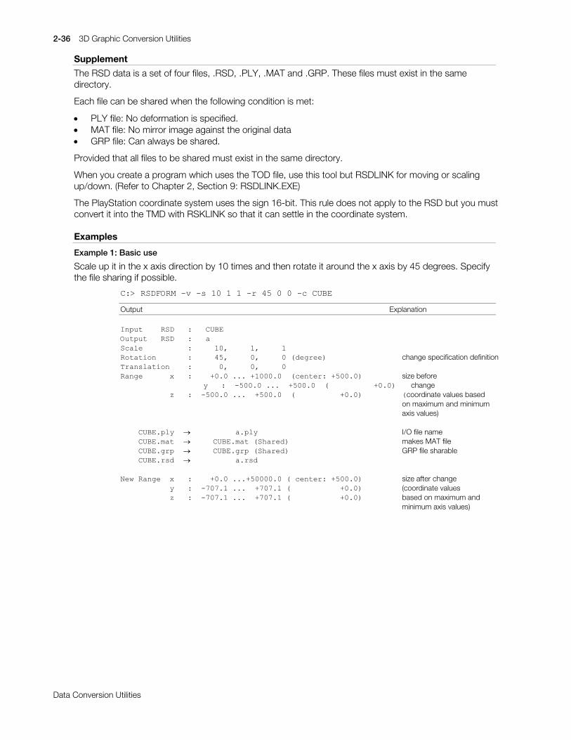
2-36 3D Graphic Conversion Utilities
Printed:11/19/98 4:16 PM By:SCEA Filename:final44Dataconv.doc Last saved by:SONY On:11/19/98 3:28 PM Comments: Master Copy, TechRef Release 4.3.
Data Conversion Utilities
Supplement
The RSD data is a set of four files, .RSD, .PLY, .MAT and .GRP. These files must exist in the samedirectory.
Each file can be shared when the following condition is met:
x PLY file: No deformation is specified.x MAT file: No mirror image against the original datax GRP file: Can always be shared.
Provided that all files to be shared must exist in the same directory.
When you create a program which uses the TOD file, use this tool but RSDLINK for moving or scalingup/down. (Refer to Chapter 2, Section 9: RSDLINK.EXE)
The PlayStation coordinate system uses the sign 16-bit. This rule does not apply to the RSD but you mustconvert it into the TMD with RSKLINK so that it can settle in the coordinate system.
Examples
Example 1: Basic use
Scale up it in the x axis direction by 10 times and then rotate it around the x axis by 45 degrees. Specifythe file sharing if possible.
&=!#56')250#0Y#0V#43#4#4#0U#78#3#3#0F#&8%(
Output Explanation
,QSXW####56'###=###&8%(2XWSXW###56'###=###D6FDOH##########=#####43/#####4/#####45RWDWLRQ#######=#####78/#####3/#####3#+GHJUHH, change specification definition7UDQVODWLRQ####=######3/#####3/#####35DQJH######[###=####.313#111#.433313##+FHQWHU=#.83313, size before
###########\###=##083313#111##.83313##+##########.313, ##change###########]###=##083313#111##.83313##+##########.313, +coordinate values based
on maximum and minimumaxis values)
####&8%(1SO\##o##########D1SO\# I/O file name####&8%(1PDW##o#####&8%(1PDW#+6KDUHG, makes MAT file####&8%(1JUS##o#####&8%(1JUS#+6KDUHG, GRP file sharable####&8%(1UVG##o##########D1UVG
1HZ#5DQJH##[###=####.313#111.8333313#+#FHQWHU=#.83313, size after change###########\###=##0:3:14#111##.:3:14#+###########.313, (coordinate values###########]###=##0:3:14#111##.:3:14#+###########.313, based on maximum and
minimum axis values)

3D Graphic Conversion Utilities 2-37
Printed:11/19/98 4:16 PM By:SCEA Filename:final44Dataconv.doc Last saved by:SONY On:11/19/98 3:28 PM Comments: Master Copy, TechRef Release 4.3.
Data Conversion Utilities
Example 2: To deform locally
Apply the -l option in the example 1 deformation. With this option, you can specify the center of gravity ofthe model as the center of rotation and scaling. Location of the model does not change. Compare this withthe result of the example 1.
&=!#56')250#0Y#0O#0V#43#4#4#0U#78#3#3#&8%(,QSXW####56'###=###&8%(2XWSXW###56'###=###D6FDOH##########=#####43/#####4/#####45RWDWLRQ#######=#####78/#####3/#####3#+GHJUHH,7UDQVODWLRQ####=######3/#####3/#####35DQJH######[###=####.313#111#.433313##+FHQWHU=#.83313,##?
###########\###=##083313#111##.83313##+##########.313,###�###########]###=##083313#111##.83313##+##########.313,##2##?############################################################?####&8%(1SO\##o##########D1SO\##############################?####&8%(1PDW##o##########D1PDW############################FHQWHU#RI####&8%(1JUS##o##########D1JUS############################JUDYLW\####&8%(1UVG##o##########D1UVG##############################2############################################################21HZ#5DQJH##[###=#0783313#111#.883313#+#FHQWHU=#.83313,##?##2###########\###=##0:3:14#111##.:3:14#+###########.313,###�###########]###=##0:3:14#111##.:3:14#+###########.313,##2
Example 3: Copying the RSD file
This software can be used as a copying tool for the RSD file. This is also available for change of the RSDname. It is useful for you to create the following batch file.
&=!#7<3(#56'&23<1%$7#(&+2#2))56')250#0R#(5#(4

2-38 3D Graphic Conversion Utilities
Printed:11/19/98 4:16 PM By:SCEA Filename:final44Dataconv.doc Last saved by:SONY On:11/19/98 3:28 PM Comments: Master Copy, TechRef Release 4.3.
Data Conversion Utilities
Example 4: Overwriting of the RSD file
This tool protects the pre-deformation RSD file from being overwritten. However, you can use this tool asan overwriting tool with the following batch file.
#(&+2#2))6(7#$5*6 5(05(0# reads all arguments=/2234,)#%(<% %%#*272#/$%(/46(7#$5*6 ($5*6(#(46+,)7*272#/2334=/$%(/45(05(0# immediately changes name to _tmp5(0UVGIRUP#0R#BWPS#($5*6(#(4#(5#(6#(7#(8#(9#(:#(;,)#(5525/(9(/#4#*272#(1'5(05(0# searches for last argument (=I/O file name)5(0=/2235,)#%(4% %%#*272#/$%(/56+,)7*272#/2235=/$%(/55(05(0# overwrites input file name (%0)5(0UVGIRUP#0R#(3#0TXLHW#BWPS5(05(0BWPS1-# completes deletion of starred files (*)5(0'(/#BWPS1-=(1'6(7#$5*6
3D Graphic Conversion Utilities 2-39
Printed:11/19/98 4:16 PM By:SCEA Filename:final44Dataconv.doc Last saved by:SONY On:11/19/98 3:28 PM Comments: Master Copy, TechRef Release 4.3.
Data Conversion Utilities
RSDLINK: Converts RSD to TMD
Version 3.72
Documentation date: 10/1/96
Description
This software converts the 3D model data (RSD) for the artist into the 3D model format (TMD) which thelibgs can deal with.
How to use
RSDLINK [options] rsd-names...
RSDLINK [options] rsd-names [options] rsd-names [options]...
RSDLINK [options] arg-files...
RSDLINK [options] prj-file
These link multiple RSD data you specify with the argument to create a TMD file. This allows you to set ascale factor and parallel move for each RSD data. (Refer to example 1.)
Unless an argument RSD name contains a path, first the current directory (.\) and then the .\RSD directoryare searched.
If there are many arguments, you can write them in a file (*.ARG) to give them. Omission of ".RSD" isallowed but ".ARG" of the argument filename must not be omitted. (Refer to example 2.)
Similarly, you can give directly a project file (*.PRJ). This case is equal to a case when you give all of theRSDs contained in the project file with the argument. At the same time, the -id option is regarded to bespecified. Omission of ".PRJ" is not allowed.
Options
-o file-name Specify an output filename. The default is "a.tmd".
-s factor Scales up or down the RSD data after the next argument (*).
-sc factor The scale factor is rounded to powers of 2. The default is 1.0. Set a proper scale factor sothat it can settle in the TMD format coordinate system because the coordinate values inthe TMD format are 16-bit integers.
-t x y x Moves the RSD data after the next argument (*). The default is (0 0 0).
-id PRJ-file Specifying the project file (MODEL.PRJ) creates an array of object ID numbers for eachobject to be created in the TMD file. The result is created in the current directory as aheader file to the C language. The output filename is identical with the TMD filenameexcept the extension which is replaced with ".h" (refer to example 3.)
-info Outputs very detailed information about the kind, vertex coordinate values and textures ofobjects which are being converted to an standard output (refer to example 5.)
-v Outputs detailed information about conversion such as the number of polygons to astandard output. Moreover, as their approximate sizes (Range: minimum and maximumvalues of the vertices (x, y and z)) in the PlayStation coordinate system are also outputted,you can check their positions or sizes before displaying them on the PlayStation board(refer to example 4.)
(*) Note: The -s and -t are effective to all the RSDs which appear after them unless theyare specified again.

2-40 3D Graphic Conversion Utilities
Printed:11/19/98 4:16 PM By:SCEA Filename:final44Dataconv.doc Last saved by:SONY On:11/19/98 3:28 PM Comments: Master Copy, TechRef Release 4.3.
Data Conversion Utilities
Main improvements from previous version (ver. 3.65)
Now able to link more RSD. Although the maximum up until now was around 500 RSD, it is now possibleto link as many as the memory will allow. With DOS, although it depends on the available conventionalmemory space, it is possible to link up to 2000 RSD.
When the file described in the RSD file cannot be found, convert the file name to all caps and search again.If the file still cannot be found, convert the name to all lower case and search again (only for SGI versions).
Constraints
The current version has the following constraints:
May not link the RSD data if there are too many polygons in a RSD data. The upper limit of the number ofpolygons depends on the numbers of vertices and normals and the free memory capacity but it is usuallyabout 5000 polygons. However, this limit applies only to "a RSD" and there is, in practice, no limit to thenumber of the RSDs to be linked and number of polygons of the whole TMD to be created.
If a RSD which does not appear in the project file is linked, "-1" is allocated to the header file.
If you specify the same RSD twice when you specify a project file, the ID value is allocated to only the firstRSD and "-1" is allocated to the second and following RSDs.
A line of the RSD file must consist of 1024 bytes or less.
Note
Never use the parallel move (-t) or scale-up/down (-s) option to create a program which uses the TOD fileoutputted by an animation tool or MKTOD. Specifying the move or scale-up/down option in conversionfrom the RSD to the TMD causes wrong movement or size of object because the movement and scalefactor for the RSD object are stored in the TOD file.
For the move and scale-up/down, use DXF2RSD (-sc -t) or RSDFORM (-s -t) in the RSD format, unlessotherwise specified. This allows more accurate and easy-to-use data to be obtained.
rsdlink performs file input/output in small units. As a result, it can take a long period of time whendesignating a network file as the input/output file. When linking a large RSD data file, please use the localdisk as much as possible.
Supplement
The image data file (TIM file) which is described in the RSD file must exist in the same directory (.\) as theRSD file exists or ..\TIM directory. RSDLINK searches the TIM file in this order.
The following table shows what TMD type the RSD is converted to by RSDLINK. Heads and items showtypes which are described in the MAT file. (Tri, Quad, Line, Sprite and others are specified with numerals inthe PLY file.) The 0x... is a header of the TMD packet. In the table, only one-sided polygons which are notsemitransparent are shown. Packet of the semitransparent or both sided polygons is the same though theheader has a different value. For details refer to "Appendix: File format RSD and RMD".
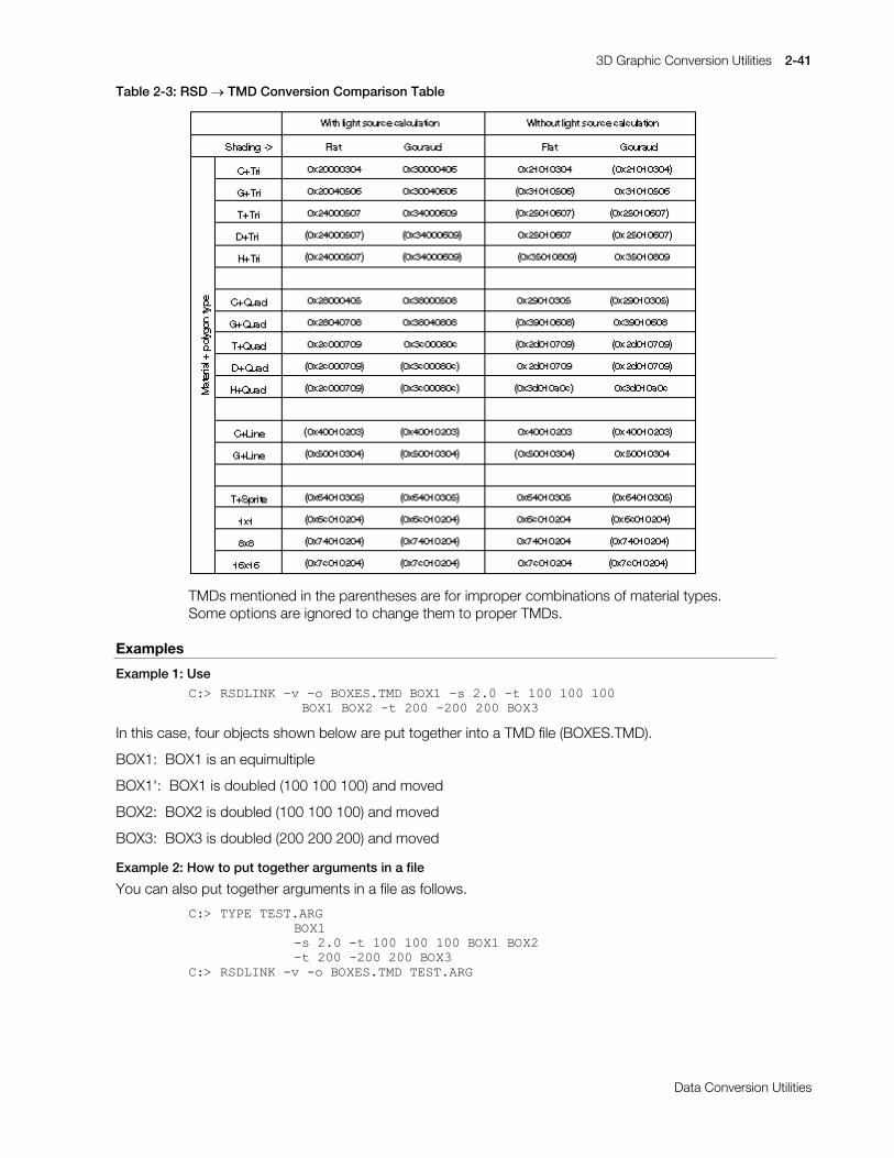
3D Graphic Conversion Utilities 2-41
Printed:11/19/98 4:16 PM By:SCEA Filename:final44Dataconv.doc Last saved by:SONY On:11/19/98 3:28 PM Comments: Master Copy, TechRef Release 4.3.
Data Conversion Utilities
Table 2-3: RSD o TMD Conversion Comparison Table
TMDs mentioned in the parentheses are for improper combinations of material types.Some options are ignored to change them to proper TMDs.
Examples
Example 1: Use&=!#56'/,1.#0Y#0R#%2;(6170'#%2;4#0V#513#0W#433#433#433
#%2;4#%2;5#0W#533#0533#533#%2;6
In this case, four objects shown below are put together into a TMD file (BOXES.TMD).
BOX1: BOX1 is an equimultiple
BOX1': BOX1 is doubled (100 100 100) and moved
BOX2: BOX2 is doubled (100 100 100) and moved
BOX3: BOX3 is doubled (200 200 200) and moved
Example 2: How to put together arguments in a file
You can also put together arguments in a file as follows.
&=!#7<3(#7(671$5*%2;40V#513#0W#433#433#433#%2;4#%2;50W#533#0533#533#%2;6
&=!#56'/,1.#0Y#0R#%2;(6170'#7(671$5*

2-42 3D Graphic Conversion Utilities
Printed:11/19/98 4:16 PM By:SCEA Filename:final44Dataconv.doc Last saved by:SONY On:11/19/98 3:28 PM Comments: Master Copy, TechRef Release 4.3.
Data Conversion Utilities
Example 3: Read-in of project file and creation of ID array
Project file ("MODEL.PRJ") is an ID table of objects which an animation tool creates.
&=!#7<3(#02'(/135-#35-<73:34H[W#DYDLODEOH#,'
9&#,'2EMHFW#1DPH
3 KHDG1UVG4 ERG\1UVG5 OBDUP1UVG6 UBDUP1UVG7 OBOHJ1UVG8 UBOHJ1UVG
If there is a file mentioned above and you execute
&=!#56'/,1.#0R#52%2170'#02'(/135-
or
&=!#56'/,1.#0R#52%2170'#0LG#02'(/135-#%2'<#+($'##/B$50#5B$50/B/(*#5B/(*
ROBO.H having the following contents is created together with ROBO.TMD. IDs of objects are registeredas elements of the array in the same order they appear in the TMD. You can use this when you want toaccess each object in the TMD from the application program.
&=!#7<3(#52%21+2-
-#70'#,'#/LVW#IRU#%52%2170'%--#&UHDWHG#E\#UVGOLQN+Y619,#DW#43=43#3<2492<7--#+&,4<<7#6RQ\#&RPSXWHU#(QWHUWDLQPHQW#,QF1#$OO#5LJKWV#5HVHUYHG1-2LQW#URERBOLVW>@# #^
4/ 2-#ERG\##-23/ 2-#KHDG##-25/ 2-#OBDUP#-26/ 2-#UBDUP#-27/ 2-#OBOHJ#-28/ 2-#UBOHJ#-2
`>

3D Graphic Conversion Utilities 2-43
Printed:11/19/98 4:16 PM By:SCEA Filename:final44Dataconv.doc Last saved by:SONY On:11/19/98 3:28 PM Comments: Master Copy, TechRef Release 4.3.
Data Conversion Utilities
Example 4: Outputs when the -v option is used&=!#56'/,1.#0Y#',12#0V#433#%2;
Output Explanation
>3@ #56'# first RSD (DINO.rsd)##56'#ILOHV#=#?36;*5$3+?'$7$?56'?GLQR1SO\/##############',121PDW/#',121JUS#######7(;>3@# #GLQR31#WLP#######7(;>3@# #GLQR41#WLP#######7(;>5@# #GLQR51#WLP texture file name#######7(;>6@# #GLQR61#WLP#######7(;>7@# #GLQR71#WLP#######7(;>8@# #GLQR81#WLP##32/<*21#####=##5:57 number of polygons##9(57(;######=##46:9 number of vertices##1250$/######=##59:4 number of normal lines##0$7(5,$/####=##58<5 amount of material##5DQJH#######=##+04;3/#0543/#049<3,0+4;3/#8;3/#5<3, minimum and maximum of
(x,y,z)>4@ #56'# ##56'#ILOHV###=#?36;*763+?'$7$?56'?%2;1SO\/################%2;1PDW/%2;1JUS second RSD (BOX.rsd)##32/<*21#####=##45##%(57(;######=###;##1250$/######=##45##0$7(5,$/####=###4##6FDOH#######=#45; unity scaling factor
(100 is rounded up to 2n)##5DQJH#######=#+09733/#09733/#09733,0+9733/#9733/#9733,## #70'# ##2XWSXW#70'##=#«D1WPG¬ output file name##70'#KHDGHU##=#######+####45#E\WHV, TMD file header size##2EMHFWV#####=######5+####89#E\WHV, total number of RSD##3ULPLWLYHV##=###5:69+#98973#E\WHV, total no. of primitives####################45#111)ODW#&RORUHG#7ULDQJOHV###################469#111*RXUDXG#&RORUHG#7ULDQJOHV contents of each mode##################5767#111)ODW#7H[WXUHG#7ULDQJOHV###################487#111*RXUDXG#7H[WXUHG#7ULDQJOHV##9HUWLFHV####=###46;7#+#443:5#E\WHV, total number of vertices##1RUPDOV#####=###59;6#+#54797#E\WHV, total no. of normal lines00000000000000000000000000000000000000007RWDO#ILOH#VL]H=#<;577#E\WHV <output file size>
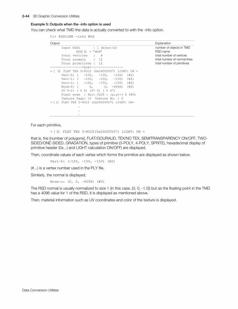
2-44 3D Graphic Conversion Utilities
Printed:11/19/98 4:16 PM By:SCEA Filename:final44Dataconv.doc Last saved by:SONY On:11/19/98 3:28 PM Comments: Master Copy, TechRef Release 4.3.
Data Conversion Utilities
Example 5: Outputs when the -info option is used
You can check what TMD the data is actually converted to with the -info option.
&=!#56'/,1.#0LQIR#%2;
Output Explanation######,QSXW#56'V#######=#4#REMHFW+V, number of objects in TMD##############56'>3@# #«%2;¬ RSD name######7RWDO#YHUWLFHV###=###; total number of vertices######7RWDO#QRUPDOV####=##45 total number of normal lines######7RWDO#SULPLWLYHV#=##45 total number of primitives00000000000000000?ER[!00000000000000000 #>#3@#)/$7#7(;#6032/<#+3[5733383:,#/,*+7=#21# ######9HUW03=#+###0483/###0483/###0483,##+&5,######9HUW04=#+###0483/###0483/###0483,##+&9,######9HUW05=#+###0483/###0483/###0483,##+&3,######1RUP03=#+######3/######3/##073<9,##+&3,######89#305=#+#3#3,#+7:#3,#+#3#7:,######3L[HO#PRGH##=#7ELW#&/87#=#+[/\, +#3#7;3,######7H[WXUH#3DJH=#43##7H[WXUH#1R1#=#3 #>4@#)/$7#7(;#6032/<#+3[5733383:,#/,*+7=#21 ###############1###############1###############1
For each primitive,
#>3@#)/$7#7(;#6032/<+3[5733383:,#/,*+7=#21#
that is, the [number of polygons], FLAT/GOURAUD, TEX/NO TEX, SEMITRANSPARENCY ON/OFF, TWO-SIDED/ONE-SIDED, GRADATION, types of primitive (3-POLY, 4-POLY, SPRITE), hexadecimal display ofprimitive header (0x...) and LIGHT calculation ON/OFF) are displayed.
Then, coordinate values of each vertex which forms the primitive are displayed as shown below.
9HUW03=#+0483/#0483/#0483,#+&5,
(#...) is a vertex number used in the PLY file.
Similarly, the normal is displayed.
1RUP0R=#+3/#3/#073<9,#+&3,
The RSD normal is usually normalized to size 1 (in this case, (0, 0, -1.0)) but as the floating point in the TMDhas a 4096 value for 1 of the RSD, it is displayed as mentioned above.
Then, material information such as UV coordinates and color of the texture is displayed.
3D Graphic Conversion Utilities 2-45
Printed:11/19/98 4:16 PM By:SCEA Filename:final44Dataconv.doc Last saved by:SONY On:11/19/98 3:28 PM Comments: Master Copy, TechRef Release 4.3.
Data Conversion Utilities
RSDUP: Converts old RSD file to HMD-compatible RSD file
Version 1.1
Documentation date: 3/2/98
Description
Converts an old RSD-formatted file to a new RSD-formatted file which conforms to HMD.
How to use
rsdup [options] RSD files ...rsdup [options] -bat TXT file
An old RSD-formatted file is converted to a new RSD-formatted file which conforms to HMD.rsdup reads multiple RSD files containing components of a single character and collects them together in asingle RSD file. The default output files are a.rsd, a.ply, a.mat and a.cod. Described in the COD file is thecomponent of the RSD file which contains the COORDINATE of the unit matrix. After the COD file isoutput, the initial location can be determined by editing the file.
Options
-o output-file Specifies the base name of the output file. If an extension isincluded it is ignored. The default base name of the output fileis "a".
-ogp Outputs an OGP file. The default output file name is a.ogp. If the-o option is used, a different base file name can be specified. Theobject group name takes the extension of each RSD file that isread.
-pvt PVT-file Specifies the PVT file which is included in the RSD file.
-cod COD-file Specifies the COD file which is included in the RSD file. In this case,the -ogp option is invalid and the output file "a.cod" is not writtenas the default.
-mot number-of-MOT-files MOT-file... Specifies the MOT files which are included in the RSD file. A singleMOT file must contain the same animation type.
Notes
x RSD files and TIM files must be in the same directory. If they are not, the relative path or absolute pathmust be specified.
x If the output file already exists, the contents are overwritten. No alert is displayed so please exercisecare.
x When the -bat option is specified, the TXT file, which is the last parameter to rsdup, is read. The targetRSD files which will be read are described in the TXT file. In this case, one file must be specified perline. (a TXT file can be output efficiently using ls *.rsd > debug.txt)
x As with the old RSD format, check to be sure there is a 1:1 correspondence for every index when theCOD file and MOT file are specified. If a 1:1 correspondence does not exist, the RSD file will not beconverted properly to HMD.

2-46 3D Graphic Conversion Utilities
Printed:11/19/98 4:16 PM By:SCEA Filename:final44Dataconv.doc Last saved by:SONY On:11/19/98 3:28 PM Comments: Master Copy, TechRef Release 4.3.
Data Conversion Utilities
x The versions of RSD format that can be used with this program are shown below. Please check theversion numbers beforehand as other versions of RSD cannot be used.
RSD File version 2.1PLY File version 2.1MAT File version 2.1, version 2.2GRP File version 2.1(In rsdup version 1.0, the GRP file is not used so the version is not checked.)
Changes in version 1.0
xý Initial release.
Changes in version 1.1
x Comments before ID are no longer output.
x PLY files that do not contain Normals can now be loaded.
x When multiple (identical) RSDs specify the same TIM, the output RSD will use a single TIM instead ofusing Includes for separate TIMs.

3D Graphic Conversion Utilities 2-47
Printed:11/19/98 4:16 PM By:SCEA Filename:final44Dataconv.doc Last saved by:SONY On:11/19/98 3:28 PM Comments: Master Copy, TechRef Release 4.3.
Data Conversion Utilities
TMD2PMD: Converts TMD to PMD
Version 1.14
Documentation date: 10/16/95
Description
Input of the TMD format file (*.TMD) which is the PlayStation 3D modeling data format creates the PMD file(*.PMD) which is the high speed modeling data format. For detail of PMD format, refer to “Appendix: Fileformat: PMD”. This software is an MS-DOS Commandline application.
How to use
TMD2PMD [options] TMD-files...
The argument can contain wildcard identifiers. Multiple files can be given to perform batch conversions. Insuch cases, each file is converted to the same file name with a .pmd extension and is created in the currentdirectory.
Options
-o output-file Specifies the output filename. The default creates a filename identical with the inputfilename in the current directory, except the extension which is replaced with “.PMD”.Input of two or more files does not allow use of this option. If you specify the wildcardwhich applies to two or more files, use of this option causes an error.
-h Shows a list of options which can be specified and an easy-to-use method.
-v Shows detailed information about conversion.
-s Sets vertex data in the PMD file to be created in sharing vertex mode.
+s Sets vertex data in the PMD file to be created in independent vertex mode. (Default)
-l Turns ON the light calculation flag in the PMD file to be created.
+l Turns OFF the light calculation flag in the PMD file to be created. (Default)
-b Turns ON the Back clip flag in the PMD file to be created. (Default)
+b Turns OFF the Back clip flag in the PMD file to be created.
-notge Turns OFF the TGE flag of all packets in the PMD file to be created.
+notge For packet TGE flag in the PMD file to be created, those in the input TMD file are copied.(Default)
Remarks
In the TMD file, texture polygons with light source calculation do not include color information. tmd2pmdsets this sort of data as a brightness of 0x80 together with R, G, B when it creates the PMD file.
Changes in Version 1.10
xý Fixed a bug in which the ABE and TGE bits in the TMD packet were not reflected in the output PMD.
Changes in Version 1.11
xý Added an option (-notge) so that the TGE bit in a TMD packet is ignored and the TGE bit in the outputPMD is forcibly set to 0.

2-48 3D Graphic Conversion Utilities
Printed:11/19/98 4:16 PM By:SCEA Filename:final44Dataconv.doc Last saved by:SONY On:11/19/98 3:28 PM Comments: Master Copy, TechRef Release 4.3.
Data Conversion Utilities
Changes in Version 1.13
xý Changed so that the directory which creates working files can be specified by the TMP environmentalvariable. Fixed a bug in which some types of polygons did not have correct vertex colors in the createdPMD file.
Changes in Version 1.14
xý Fixed a bug in which TMD files containing only gradation polygons were not converted correctly.

3D Graphic Conversion Utilities 2-49
Printed:11/19/98 4:16 PM By:SCEA Filename:final44Dataconv.doc Last saved by:SONY On:11/19/98 3:28 PM Comments: Master Copy, TechRef Release 4.3.
Data Conversion Utilities
TMDSORT/INFO: Sorts and displays TMD files
Version 1.25
Documentation date: 4/1/96
Description
tmdsort - This software sorts the 3D model data file (TMD) by packet type. This minimizes branching bypacket type at painting. This is used to realize a high painting speed.
tmdinfo - Displays the contents of the TMD file.
How to use
TMDSORT [options] TMD-fileTMDINFO [-v _ -l ] TMD-file
This sorts packets in each object in the TMD file you specified with the argument and outputs the result intoa new TMD file. Also, the total number of each packet type is output to a standard output. Omission of“.TMD” is allowed.
Options
-o file-name Specify an output TMD filename. The default is “a.tmd”. However, overwriting to the inputfile is not allowed.
-n Executes no sorting but outputs information about the input TMD to a standard output.
-v or -l Outputs very detailed information about the type, vertex coordinate values and texture ofall packets to a standard output. The display correspond to the output of RSDLINK-info.Refer to rsdlink.txt.
If this tool is copied and the name is changed to tmdinfo.exe (tmdinfo with SGI) it will bemade into a state in which the -n option has been specified in the default. Also, it will bepossible to output the total number of vertices and normals along with their location, size,etc. in the PS coordinate system. Although no sorting is carried out, this is useful inconfirming TMD file contents. Only the -v (or -1) option can be specified.
Main improvements over previous version (ver. 1.1)
The location and size (“Range: minimum/maximum value of vertex (x,y,z)”) in the PS coordinate system ofthe input TMD can now be output (tmdinfo only).
Constraints
The number of vertices (and normals) per object must be 8189 or less when the -v option is used. Unlessthe -v option is used, this constraint is meaningless.
Sorting is executed, object by object in the TMD. A different object is not sorted even if it exists in the sameTMD.
2-50 3D Graphic Conversion Utilities
Printed:11/19/98 4:16 PM By:SCEA Filename:final44Dataconv.doc Last saved by:SONY On:11/19/98 3:28 PM Comments: Master Copy, TechRef Release 4.3.
Data Conversion Utilities
XHMD: Converts an HMD data file to labp format
Version 1.20
Documentation date: 10/26/98
Description
Converts an HMD data file to labp format.
The following description applies to Version 1.20.
How to use
xhmd [options] labp-file >out-file
The xhmd command takes a single file as input and writes the result on stdout.
When used with the labp command (labp = label processor, HMD assembler.
Please see the labp document), HMD data can be updated relatively simply.
General workflow is shown below using IRIX as an example.
$ xhmd foo.hmd >foo.lab$ vi foo.lab # Edit HMD data$ /usr/lib/cpp -I /usr/local/include foo.lab >foo2.hmd # Create updated HMD data (example using UNIX).
# /usr/local/include/hmd/hmd.def exists.
Options
-v Print version information on stderr.
Notes
x If the HMD input file contains invalid pointer information, the xhmd commandwill terminate abnormally. In this case, output is limited to what informationis available.
x Stdin cannot be used as input.
x Polygon section analysis is not performed. Information that is output is an enumeration of simple data.
Changes in Version 1.02
xý The bug which made it impossible for any Shared Polygon Primitives, except for those linked to post-process to be processed, has been fixed.
xý In order to make it compatible with the partial C language pre-processor, the format of the outputcomments has been changed from labp format to C language pre-processor. Please refer to the labpdocumentation for details.
xý Error processing when incorrect data is input has been added.
Changes in Version 1.10
xý Now compatible with the HMD MIMe Format and Ground Primitives which were changed in PlayStationLibrary 4.1.
Changes in Version 1.11
xý The mistake in the output result which incorrectly spelt “SPLINE” as “SPRINE” was corrected.

3D Graphic Conversion Utilities 2-51
Printed:11/19/98 4:16 PM By:SCEA Filename:final44Dataconv.doc Last saved by:SONY On:11/19/98 3:28 PM Comments: Master Copy, TechRef Release 4.3.
Data Conversion Utilities
Changes in Version 1.12
xý The upper eight bits of the polygon index in the polygon and shared polygon primitives can now beinterpreted as a polygon division parameter.
Changes in Version 1.15
xý Now compatible with the animation formats based on the six types of rotational order introduced inLibrary 4.2.5.
Changes in Version 1.16
xý It is possible to specify the size of an image primitive header with no CLUT as 1, however a bug whichcaused this to be recognized as an error was fixed.
Changes in Version 1.20
xý Reverse assembling of polygon data is now possible.
xý Processing when multiple labels are assigned to the same address is now possible.

2-52 3D Graphic Conversion Utilities
Printed:11/19/98 4:16 PM By:SCEA Filename:final44Dataconv.doc Last saved by:SONY On:11/19/98 3:28 PM Comments: Master Copy, TechRef Release 4.3.
Data Conversion Utilities

Printed:11/19/98 4:16 PM By:SCEA Filename:final44Dataconv.doc Last saved by:SONY On:11/19/98 3:28 PM Comments: Master Copy, TechRef Release 4.3.
Data Conversion Utilities
Chapter 3:2D Graphics Conversion Utilities

3-2 2D Graphics Conversion Utilities
Printed:11/19/98 4:16 PM By:SCEA Filename:final44Dataconv.doc Last saved by:SONY On:11/19/98 3:28 PM Comments: Master Copy, TechRef Release 4.3.
Data Conversion Utilities

2D Graphics Conversion Utilities 3-3
Printed:11/19/98 4:16 PM By:SCEA Filename:final44Dataconv.doc Last saved by:SONY On:11/19/98 3:28 PM Comments: Master Copy, TechRef Release 4.3.
Data Conversion Utilities
BMP2TIM: Converts BMP to TIM
Version 2.2
Documentation date: 1/25/96
Description
This software converts the Windows BMP file into the PlayStation image data file (TIM).
How to use
BMP2TIM [options] BMP-files ...
Input of the Windows 3.0 BMP format image data file creates the PlayStation TIM file. The argument cancontain wildcard identifiers. Multiple files can be given to perform batch conversions. Omission of the".BMP.
Options
-o output-file Specify an output filename. The default is to use the input filename with the extension‘.tim’ and write it to the current directory.
-org x y Specify the VRAM image data area origin. The default is (0,0).
-plt x y Specify the VRAM pallet (CLUT) area position. The default is (0,480).
-t Turns the transparent control bit ON against any other color than (0 0 0). Any other colorthan (0 0 0) turns semitransparent. The default is for all colors to be non-transparent.
-b Turns the transparent control bit OFF against (0 0 0).(0 0 0) turns transparent. The defaultlets (0 0 0) turn black.
-v Shows detailed information about conversion.
Major changes from previous version 2.1
This version allows creation of a TIM with no CLUT from a Windows BMP file. To do this, use the “-plt x y”option with a negative x or y: for example:
bmp2tim -plt -1 -1 a.bmp
Major changes from versions prior to 2.1
Now correctly converts even when the width is not 4x.
Even when an absolute path is provided for an input image file (if not explicitly specified with the -o option),a TIM file is created in the current directory.
The -mode option was eliminated. The file is converted to the mode closest to the size of the input BMPdata pixels. Please use Photoshop or something similar to reduce the number of colors.
Changed so that the -t option can be set as semi-transparent for (0 0 0). In the previous version the defaultfor (0 0 0) was transparent, but in this version it is displayed as black. If sprite areas other than charactersare to be made transparent, (with Photoshop or something similar), specify the -b option for those areaswhich are to remain black when converting.
Constraints
The BMP compressed format is unavailable for the current version.
3-4 2D Graphics Conversion Utilities
Printed:11/19/98 4:16 PM By:SCEA Filename:final44Dataconv.doc Last saved by:SONY On:11/19/98 3:28 PM Comments: Master Copy, TechRef Release 4.3.
Data Conversion Utilities
PICT2TIM: Converts PICT to TIM
Version 3.1
Documentation date: 10/17/94
Description
This software converts the Macintosh PICT file into the PlayStation image data file (TIM).
How to use
PICT2TIM [options] PICT-files ...
Input of the Macintosh PICT format image data file creates the PlayStation TIM file. The wildcard is availablefor the argument. You can input and convert multiple files at a time.
Options
-o output-file Specify an output filename. The default creates a filename identical with the input filenameat the current directory, except extension which is converted into the ".TIM".
-org x y Specify the VRAM image data area origin. The default is (0,0).
-plt x y Specify the VRAM pallet (CLUT) area position. The default is (0,480).
-t Turns the transparent control bit ON against any other color than (0 0 0). Any other colorthan (0 0 0) turns semitransparent. The default lets all colors turn nontransparent.
-b Turns the transparent control bit OFF against (0 0 0).(0 0 0) turns transparent. The defaultlets (0 0 0) turn black.
-v Shows detailed information about conversion.
Constraints
The current version has the following constraints:
x Convertible PICT data is limited to the Pixmapx 32-bit PICT data cannot be convertedx JPEG compressed PICT data cannot be converted
2D Graphics Conversion Utilities 3-5
Printed:11/19/98 4:16 PM By:SCEA Filename:final44Dataconv.doc Last saved by:SONY On:11/19/98 3:28 PM Comments: Master Copy, TechRef Release 4.3.
Data Conversion Utilities
RGB2TIM: Converts RGB to TIM
Version 2.1
Documentation date: 4/1/96
Description
This software converts the RGB format image data file into the PlayStation image data file (TIM).
How to use
RGB2TIM-size w h [options] input-file
Input of the RGB format image data file creates the PlayStation TIM file. For -size, you must specifynumbers of pixels for the width and height of the input image. The input data is the 24-bit interleaved RGBdata. The wildcard is available for the argument but you can convert only one file at a time. Althoughmultiple RGB data can be converted together, since options such as size, bit mode, etc. become commonto all data, individual output file names cannot be specified.
Options
-o output-file Specify an output filename. The default creates a filename identical with the inputfilename at the current directory, except extension which is converted into the".TIM".
-org x y Specify the VRAM image data area origin. The default is (0,0).
-plt x y Specify the VRAM pallet (CLUT) area position. The default is (0,480).
-mode 4|8|16|24 Specify a pixel size for the output TIM data. The default is the 16-bit mode.
-t Turns the transparent control bit ON against any other color than (0 0 0). Anyother color than (0 0 0) turns semitransparent. The default lets all colors turnnontransparent.
-b Turns the transparent control bit OFF against (0 0 0).(0 0 0) turns transparent. Thedefault lets (0 0 0) turn black.
-skip n Specify the number of bytes which are skipped from the head of file. The defaultis 0.
-v Shows detailed information about conversion.
Main changes from previous version
Creation of a TIM file with no CLUT is now possible (-plt option).
The -size option correctly specifies width only and when the height is given a value less than 0 , the heightis automatically calculated. Cases where only the height is correctly specified are treated similarly.
Multiple RGB data can now be converted together. However, common options are applied.
Supplement
Too many colors of the RGB data which is inputted may cause conversion of it to 4 or 8-bit mode to beimpossible. In such case, reduce beforehand the number of colors with Photoshop and others.
3-6 2D Graphics Conversion Utilities
Printed:11/19/98 4:16 PM By:SCEA Filename:final44Dataconv.doc Last saved by:SONY On:11/19/98 3:28 PM Comments: Master Copy, TechRef Release 4.3.
Data Conversion Utilities
TIMTOOL
Working with projects
Each project contains a list of all the TIM images currently loaded, as well as information such as theGraphics Mode currently used. The project information changes when you add or remove a TIM imagefrom the project. If the project information has changed, when you select to start a new project, save thecurrent project or exit the application, you will be asked if you want to save the current project.
Note: If any of the TIM images have been modified, you will firstly be asked if you wish to save the modifiedTIM images. Modifications include changes made to the TIM or CLUT position, and changes made to theSemiTransparency of any of the CLUT elements.
Loading TIM images into the current project
In order to load TIM images into the current project, you can select either the ‘Add Tim(s)’ button, the ‘TimOptions’, ‘Add to List’ menu item or the ‘Ctrl + A’ shortcut. The standard Windows ’95 ‘Open File’ dialogbox will appear. From here, you can select a single TIM image file by clicking on it, or multiple TIM imagefiles by either using the shift and ctrl keys, or by dragging a selection area around all the files you wish toload.
Note: Any directories selected will be ignored.
Positioning TIM images within the Frame Buffer
The easiest way to position TIM images within the frame buffer is to hold the left mouse button down overthe TIM image within the Frame Buffer, and drag the image to the required position before releasing themouse button. Notice that the image will snap to both the Texture Page sides and to all sides of existingTIM images. This makes positioning of the TIM images very easy.
Another way of positioning the TIM images is to select the TIM image (either by clicking on it in the framebuffer or selecting its name from the tree view) and modifying the X and Y text box entries for the TIMimage.
Note: There is no automatic sort of TIM images within the frame buffer. A generic sort procedure wouldnot work for all developers as there are usually a number of conditions that must be taken into account forthe sort, (i.e., the three small grass textures and the road textures must be located within the same texturepage, the three title images must be located at the same position etc.). Rather that having an interfacewhereby the user could enter this information into the program before sorting, and maintain it for additionsand deletions to the project’s image list, the interface was enhanced to enable the user to quickly be ableto correctly place the images where they pleased (i.e., drag and drop, snapping etc.).
Positioning the CLUTs of 4-bit and 8-bit TIM images within the Frame Buffer
One way of positioning the CLUTs of 4-bit or 8-bit TIM images is to select the TIM image (either by clickingon it in the frame buffer or selecting its name from the tree view) and modifying the CLUT X and Y text boxentries for the TIM image.
Autosort CLUTs
If you have a lot of CLUTs to position, you can arrange them all into a selectable area. In order to do this,select an area in the frame buffer by holding down the Shift key and dragging an area with the mouse in theframe buffer or texture page preview area. The selection will be snapped to a suitable scale. Select the‘Clut Options’, ‘Autosort 4-bit CLUTs into selected area’ in order to automatically sort the 4-bit CLUTs, orselect the ‘Clut Options’, ‘Autosort 8-bit CLUTs into selected area’ in order to automatically sort the 8-bitCLUTs.
If you have not selected enough area in order to be able to sort all of the CLUT’s, an error message will bedisplayed and the sorting will be cancelled.
2D Graphics Conversion Utilities 3-7
Printed:11/19/98 4:16 PM By:SCEA Filename:final44Dataconv.doc Last saved by:SONY On:11/19/98 3:28 PM Comments: Master Copy, TechRef Release 4.3.
Data Conversion Utilities
Note: Any 4-bit TIM images with CLUTs greater than 16 x 1, or any 8-bit TIM images with CLUTs greaterthan 256 x 1 will be ignored during this sort.
Note: The automatic sort for 8-bit CLUTs will ignore the width of the selection if it is under 256 pixels inwidth.
Importing and converting Windows BMP, JPEG, TIFF and PCX files
TIM Tool can import images from the following image file formats:
x Windows BMP Imagex JPEG Imagex TIFF Imagex PCX Image
In order to import and convert an image of one of the above types, select the ‘File’, ‘Import Image’ menuitem. A dialog box will appear, allowing you to select one or more image files.
Note: If you select an image that is not aligned properly (e.g., 8-bit images need to be of an even width),the converter will automatically align the converted TIM image properly.
If you select a single image, the first of the two image areas to the right of the screen will display a scaledversion of the image. The second image will display the image after it has been converted to the selectedimage depth (either 4, 8, 16 or 24-bit). The conversion will check to see if a TIM image file exists with thesame root name (e.g., if converting forest.bmp, the program will check for a file called forest.tim). If the fileexists, the conversion extracts the image and CLUT position and the previously converted color depth fromthe existing TIM image file.
If you select multiple images, the first of the two image areas to the right of the screen will display a scaledversion of the last image to be selected. The second image will display this image after it has beenconverted to the selected image depth (either 4, 8, 16 or 24-bit).
If you select the ‘Set for Black’ option from the ‘Semi Transparent Information’ area, all of the colors in theimage with the value 0 will have their STP bit set.
If you select the ‘Set for all Colors except Black’ option from the ‘Semi Transparent Information’ area, all ofthe colors in the image with a value not equal to 0 will have their STP bit set.
If you select both the ‘Set for Black’ option and the ‘Set for all Colors except Black’ from the ‘SemiTransparent Information’ area, all of the colors in the image will have their STP bit set.
If you select a single image to convert to a 16-bit TIM image file, the ‘Use Alpha Mask Image forTransparency’ check box becomes selectable. This allows you to select an Alpha Mask Image file whichwill be used to set the STP bits within previously selected TIM image file. The Alpha Mask Image file shouldpreferably contain black and white information, although the conversion uses the average of the RGB valueof each pixel to decide whether the pixel in the Alpha Mask Image file should be interpreted as black orwhite. Black areas will set the STP bit, whereas white areas will leave the STP bit clear. The Alpha MaskImage file must be the same size as the image file to be imported.
Semi Transparent Information
Color information for the PlayStation is stored in 1555 format (1 bit for the SemiTransparent information(STP) and 5 bits each for the RGB information). The color 0 is ignored by the PlayStation hardware (it isused for ‘full’ transparency). In order to be able to use the color black as a drawn color, you can set theSTP bit of all colors with the value 0, so that the hardware doesn’t see it as the value for ‘full’ transparencyany more.
However, if you are already using the STP bit for semi transparency (e.g., the program has called theSetSemiTrans() function), this value will be picked up as a semi-transparent black. In order to get a non-transparent ‘pure’ black in this case is to leave the STP bit clear and modify the Red and/or Green and/orBlue information so that the color is nearly black (e.g., 1 for Red, 0 for Green and 0 for Blue). The humaneye will not notice the difference, but fortunately the PlayStation hardware will.
3-8 2D Graphics Conversion Utilities
Printed:11/19/98 4:16 PM By:SCEA Filename:final44Dataconv.doc Last saved by:SONY On:11/19/98 3:28 PM Comments: Master Copy, TechRef Release 4.3.
Data Conversion Utilities
Modifying the STP bits of 4-bit and 8-bit TIM images
If you have loaded a 4-bit or 8-bit TIM file, you can view the images CLUT and modify the STP of eachCLUT entry. Select the required 4-bit or 8-bit TIM image from the frame buffer or tree view and either right-click the TIM Preview Image area and choose the ‘CLUT Options’ menu item, or select the ‘CLUT Options’,‘CLUT Options’ menu item.
The ‘CLUT Options’ dialog box will appear, showing the current CLUT for the selected image in the lowerleft hand corner, and a preview of the image in the lower right hand corner. From this dialog, you can setthe STP of individual CLUT entries by either double-clicking the CLUT entry, or selecting the CLUT entryand clicking the ‘Semi Transparent’ check box. This will modify the TIM image, so when you want to saveyour changes, select the ‘TIM Options’, ‘Save Modified TIM’s’ menu item.
The ‘CLUT Position’ area enables you to temporarily render the TIM image using a different CLUT, specifiedby modifying the X and Y position edit boxes.
Saving out the information to a parsable text file
If you select the ‘TIM Options’, ‘Save Map File’ menu option, a dialog box appears prompting you for a filename for the map file. This map file contains parsable text information about all the TIM image filescurrently loaded into the project. A parser can be created extremely easily, especially if the programmerhas tools that work with Windows .INI files.
An example of the file format is as follows:
[TIM_1]File=T:\TEXTURES\Barier2.timX=976Y=64Width=16Height=16ColourDepth=4ClutX=864ClutY=192
[TIM_2]File=T:\TEXTURES\Chimney.timX=956Y=128Width=4Height=64ColourDepth=4ClutX=880ClutY=192
[TIM_3]File=T:\TEXTURES\Clump.timX=1008Y=64Width=16Height=64ColourDepth=4ClutX=864ClutY=193

2D Graphics Conversion Utilities 3-9
Printed:11/19/98 4:16 PM By:SCEA Filename:final44Dataconv.doc Last saved by:SONY On:11/19/98 3:28 PM Comments: Master Copy, TechRef Release 4.3.
Data Conversion Utilities
Saving all the images as one or more large TIM files to speed up loading times
Loading a lot of separate image files from the CD can be fairly slow. In order to speed up loading, animage of the frame buffer can be built up and saved as a large single image file. TIM Tool has a featurewhich allows you to perform this easily.
If you select an area in the frame buffer (by holding down the ‘Ctrl’ button and dragging an area with themouse), and select the ‘TIM Options’, ‘Save area as 16-bit TIM’ menu option, a dialog will appearprompting you for a filename for the TIM image file.
Figuring out what the Texture Page Preview is showing
The texture page preview shows what the PlayStation hardware sees when in the current texture page atthe current color depth. If, for example, you have selected a texture page to preview in 8-bit, all the 8-bitimages in that texture page will be displayed in the texture page preview. All other non 8-bit images will bedisplayed as gridded areas, indicating that some image is located there, allowing the user to snap to theseimages.
Note: When you click on an image in the frame buffer, the texture page automatically renders at theselected images’ color depth.
Note: 24-bit images cannot be used as textures by the PlayStation hardware, and are therefore notdisplayed in the texture page preview image.

3-10 2D Graphics Conversion Utilities
Printed:11/19/98 4:16 PM By:SCEA Filename:final44Dataconv.doc Last saved by:SONY On:11/19/98 3:28 PM Comments: Master Copy, TechRef Release 4.3.
Data Conversion Utilities
TIM2BMP: Converts TIM to BMP
Version 1.2
Documentation date: 6/22/98
Description
This software converts a PlayStation texture file into Windows image data.
How to use
tim2bmp [option] input-file...
Input of the PlayStation TIM file (*.TIM) creates a Windows 3.0 BMP format image data file.
Options
-c If this option is selected when the input data is in black and white binary 16bit mode,
the 8 bit index format bit map file is output.
Limitations
Not compatible with BMP compressed format.
16bit mode input data is converted to 24bit map file.
The MS-DOS Wild card can be used when specifying the input-file.
Changes in Ver 1.1
xý A bug which caused 4-bit mode and 8-bit mode TIM data to be converted incorrectly, was fixed.
Changes in Ver 1.2
xý A bug which caused the extension not to be attached to the output file when converting data from a filehaving eight letters (not including the file name extension), was fixed.

2D Graphics Conversion Utilities 3-11
Printed:11/19/98 4:16 PM By:SCEA Filename:final44Dataconv.doc Last saved by:SONY On:11/19/98 3:28 PM Comments: Master Copy, TechRef Release 4.3.
Data Conversion Utilities
TIMPOS: Changes VRAM in TIM
Version 1.1
Documentation date: 5/1/96
Description
This software changes the VRAM image and pallet (CLUT) addresses stored in the PlayStation image datafile (TIM).
How to use
TIMPOS [options] input-file image-x image-y [clut-x clut-y]
For TIM file given by the argument, set the VRAM addresses to which the image and pallet (CLUT) arelocated. Addresses which you set are coordinate values of the top of the left side of the image and pallet.The VRAM space is 1024 wide x 512 long. Use of the argument does not allow you to set only the palletVRAM address. Set the image VRAM address at the same time. If you enter a negative number for anyaddress, the address is never changed. This allows you to change only the pallet VRAM address(Example 1). Also, if a negative number is given as a CLUT address, a TIM file with no CLUT will be created.When the CLUT address is not changed, specify only the image address (Example 2).
Omission of the extension ".TIM" of the TIM filename given by the argument is allowed.
Options
-o output-file Specify an output filename. The default is a filename identical with the input filename.
-v Outputs information about the input file and conversion to a standard output. Input of onlythe TIM file together with this option allows you to know the current address information.
Examples
Example 1: Changing only pallet address&=!7,0326#7(6717,0#0404#3833
Example 2:WLPSRV#WHVW1WLP#973#3# +FKDQJH#RQO\#LPDJH#DGGUHVV,
WLPSRV#WHVW1WLP#973#3#04#3# +&UHDWH#7,0#ZLWK#QR#&/87,
Changes from previous version (ver. 1.0)
When a negative number is set as the CLUT address, a TIM file with no CLUT is created.
An SGI version has been added.
Note
A TIM file with no CLUT cannot be converted to a TIM file with a CLUT.

3-12 2D Graphics Conversion Utilities
Printed:11/19/98 4:16 PM By:SCEA Filename:final44Dataconv.doc Last saved by:SONY On:11/19/98 3:28 PM Comments: Master Copy, TechRef Release 4.3.
Data Conversion Utilities
TIMUTIL: Allows multiple TIM, BMP, PICT and RGB conversions
Version 1.36
Documentation date: 4/3/95
Description
TIM utility is a Windows application which allows mutual conversion of the bit map formats of thePlayStation TIM, Windows BMP, Macintosh PICT and general-purpose RGB. Execute it by double clickingon the icon registered in either the file manager or program manager. Since timutil help can be displayed inthe help menu, please refer to this for details.
Options
None
Notes
timutil uses SPIN.VBX. Install SPIN.VBX in the /WINDOWS/SYSTEM.
PICT which do not contain any mixed-type TIM, compressed format BMP, JPEG compressed PICT, or32bit PICT bit maps cannot be read.
Mixed-type TIM, compressed format BMP, JPEG compressed PICT format cannot be written. Also, the bitdepth of the write file is limited to 4,8,16 or 24 bits.
For example, with conversions which reduce the bit depth such as from 16bit data to 8 bit, the colorinformation is approximated. At such times, since it approximates the color map allocated on average toeach R, G and B, rather than to the processes such as color compression, the color resolution may bedecreased.
As a general principle, files which have been read cannot be overwritten. However, since the read formatand write formats are both TIM, overwriting is possible when only the image starting point or the palettestarting point are changed. This function is equivalent to the command line version of timpos.exe.
Changes in Ver 1.10
xý The TIM file can now display to the artist board (DTL-H200). This is equivalent to the command lineversion timview.exe.
xý The timpos.exe functions have been unified.
xý A ‘Save all files’ selection has been added to the file menu.
Changes in Ver 1.15
xý The I/O address which is used to display the TIM file to the artist board (DTL-H200) can now be set inaboard.exe.
xý ‘Settings’ has been added to the file menu.
xý The conversion parameter default value can be changed.
xý When switching between the ‘TIM display’ and ‘Screen resolution’ the display resolution will now berelocated to the middle of the screen.
Changes in Ver 1.20
xý A ‘Writing palette’ list has been added to the ‘Parameter settings window’ and the multi-CLUT TIM cannow be operated.
xý The palette contents are now faithfully reflected when converting image files with identical bit lengths.

2D Graphics Conversion Utilities 3-13
Printed:11/19/98 4:16 PM By:SCEA Filename:final44Dataconv.doc Last saved by:SONY On:11/19/98 3:28 PM Comments: Master Copy, TechRef Release 4.3.
Data Conversion Utilities
Changes in Ver 1.30
xý ‘TIM layout’ has been added to the window menu.
xý The TIM file image and palette location can now be graphically edited.
Changes in Ver 1.35
xý The height of the ‘Display area’ in the ‘TIM layout’ dialog which was 240, has been changed inconsideration of the double buffer so that the area displayed on screen now has a height of 480(two vertical 240 height areas).
xý The bug in ‘TIM layout’ which caused TIM files to be displayed abnormally when the original point ofthe image did not fit within the texture page boundary has been corrected.
xý It is now possible to open RSD files. At that point all the TIM files included in the RSD file will operate asif they have been opened.
xý The current directory can now be changed when a file has been opened within drag and drop from thefile manager or from a previously-opened file list. As a result, the directory containing the files whichwere last successfully opened becomes the current directory (previously the current directory waschanged only in cases where the file dialog was used when the file was opened from the ‘Open’ menuor when the directory was changed with ‘Save all files’).
xý The bug in which an overwrite check to an identical file was not performed when the write palette waschanged has been corrected.
Changes in Ver 1.36
xý The bug whereby a BMP file in which the number of colors used was lower than the number of colorscalculated from the bit depth and could not be read has been corrected.
How to use
Selection of "Bit map file" sub-option from "Open..." option of the file menu lets you access the ParameterSetting window. Properly change parameter values and then press the "Convert..." button. Alternatively,you can select the "Give name to save..." option from the file name. The File Save dialog pops up. Enteringa post-conversion filename starts format conversion.
You can drag an input file from the File Manager to drop it in the TIM utility window instead of using the"Open..." command.
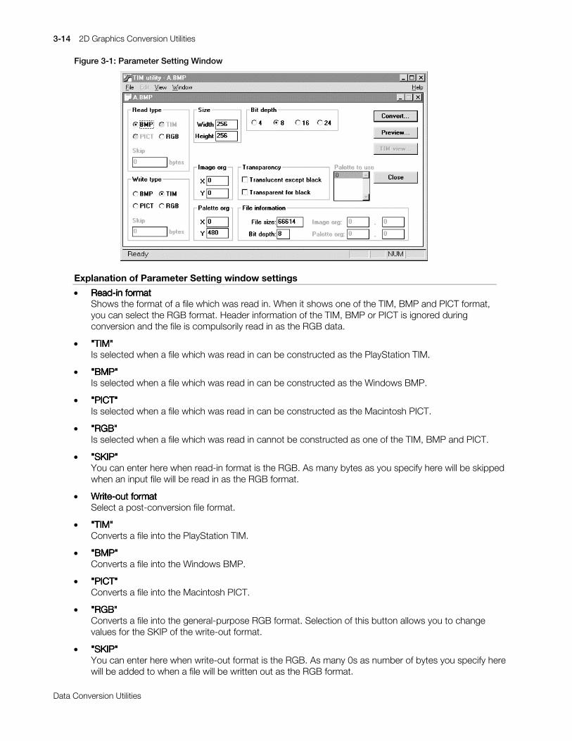
3-14 2D Graphics Conversion Utilities
Printed:11/19/98 4:16 PM By:SCEA Filename:final44Dataconv.doc Last saved by:SONY On:11/19/98 3:28 PM Comments: Master Copy, TechRef Release 4.3.
Data Conversion Utilities
Figure 3-1: Parameter Setting Window
Explanation of Parameter Setting window settings
x Read-in formatRead-in formatRead-in formatRead-in formatShows the format of a file which was read in. When it shows one of the TIM, BMP and PICT format,you can select the RGB format. Header information of the TIM, BMP or PICT is ignored duringconversion and the file is compulsorily read in as the RGB data.
x "TIM"TIM"TIM"TIM""""Is selected when a file which was read in can be constructed as the PlayStation TIM.
x "BMP"BMP"BMP"BMP""""Is selected when a file which was read in can be constructed as the Windows BMP.
x "PICT"PICT"PICT"PICT""""Is selected when a file which was read in can be constructed as the Macintosh PICT.
x "RGB"RGB"RGB"RGB""""Is selected when a file which was read in cannot be constructed as one of the TIM, BMP and PICT.
x "SKIP""SKIP""SKIP""SKIP"You can enter here when read-in format is the RGB. As many bytes as you specify here will be skippedwhen an input file will be read in as the RGB format.
x Write-out formatWrite-out formatWrite-out formatWrite-out formatSelect a post-conversion file format.
x "TIM"TIM"TIM"TIM""""Converts a file into the PlayStation TIM.
x "BMP"BMP"BMP"BMP""""Converts a file into the Windows BMP.
x "PICT"PICT"PICT"PICT""""Converts a file into the Macintosh PICT.
x "RGB"RGB"RGB"RGB""""Converts a file into the general-purpose RGB format. Selection of this button allows you to changevalues for the SKIP of the write-out format.
x "SKIP""SKIP""SKIP""SKIP"You can enter here when write-out format is the RGB. As many 0s as number of bytes you specify herewill be added to when a file will be written out as the RGB format.
2D Graphics Conversion Utilities 3-15
Printed:11/19/98 4:16 PM By:SCEA Filename:final44Dataconv.doc Last saved by:SONY On:11/19/98 3:28 PM Comments: Master Copy, TechRef Release 4.3.
Data Conversion Utilities
x SizeSizeSizeSizeYou can enter here when read-in format is the RGB. You must always enter here to construct bytestring of the input file as the RGB format image data. If the image data size calculated from a valueentered here and a value entered for the SKIP of the read-in format is larger than the size of a file whichis inputted, it causes an error. If it is smaller, it lets a warning panel pop up.
x Image originImage originImage originImage originYou can enter here when write-out format is the TIM. Set the PlayStation VRAM image origincoordinates which are inserted in the output TIM file.
x Pallet originPallet originPallet originPallet originYou can enter here when write-out format is the TIM and the bit depth is 8 or less. Set the PlayStationVRAM pallet (CLUT) origin coordinates which are inserted in the output TIM file.
x Transparent controlTransparent controlTransparent controlTransparent controlYou can set the transparent control when write-out format is the TIM and the bit depth is 16 or less.
Selection of "Any other color than the black is semitransparent" option sets the transparent control bitto 1 for any pallet entry which has any other value than 0 for one of R, G and B.
Selection of "Black is transparent" option sets the transparent control bit to 0 for any pallet entry whichhas 0s for all of R, G and B. Lack of this selection lets any color which has 0s for R, G and B turnnontransparent black.
x Bit depthBit depthBit depthBit depthSpecify the number of bits per pixel of the output file.
When write-out format is the BMP, you can specify one of 4, 8 and 24-bit. When it is the PICT, you canspecify one of 4, 8 and 16-bit. When it is the RGB, only 24-bit is available.
x Write-out palletWrite-out palletWrite-out palletWrite-out palletSelect a pallet which is written out to a post-conversion file when read-in format is the TIM and multiplepallets are provided. Pallet which you select here will be also used in the Display and TIM display.
If you set "Reflect on origin" of "Write-out pallet" with "Set..." command of the file menu, Y coordinatevalue of the pallet origin increases or reduces automatically, depending on the place of the selectedentry in the write-out pallet list.
x Information about read-in fileInformation about read-in fileInformation about read-in fileInformation about read-in fileShows the read-in file size and pixel depth.
It shows "Image origin" when read-in format is the TIM. Moreover, it also shows the "Pallet origin" whenthe "bit depth" is 8 or less.
x ConversionConversionConversionConversionExecutes format conversion according to parameters you set. As the File Save dialog pops up, enter apost-conversion filename. This function is equal to "Give name to save..." option of the file menu.
x DisplayDisplayDisplayDisplayReads in a file according to the current read-in format and displays it. Colors are approximated whenthe bit depth of the read-in file is larger than that of a display you use. (The current version may requiremuch processing time.)
x TIMTIMTIMTIM display display display displayDisplays file contents on the Artist board when the current read-in format is the TIM. Pressing thisbutton lets you access the following dialog.
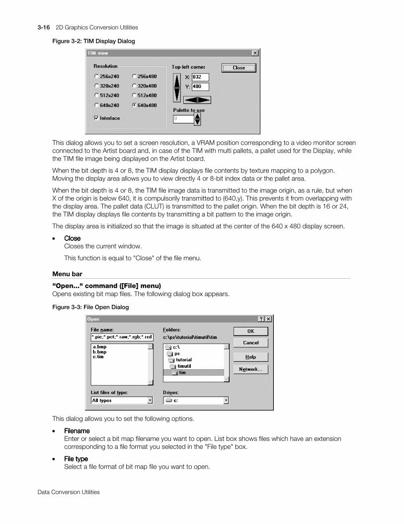
3-16 2D Graphics Conversion Utilities
Printed:11/19/98 4:16 PM By:SCEA Filename:final44Dataconv.doc Last saved by:SONY On:11/19/98 3:28 PM Comments: Master Copy, TechRef Release 4.3.
Data Conversion Utilities
Figure 3-2: TIM Display Dialog
This dialog allows you to set a screen resolution, a VRAM position corresponding to a video monitor screenconnected to the Artist board and, in case of the TIM with multi pallets, a pallet used for the Display, whilethe TIM file image being displayed on the Artist board.
When the bit depth is 4 or 8, the TIM display displays file contents by texture mapping to a polygon.Moving the display area allows you to view directly 4 or 8-bit index data or the pallet area.
When the bit depth is 4 or 8, the TIM file image data is transmitted to the image origin, as a rule, but whenX of the origin is below 640, it is compulsorily transmitted to (640,y). This prevents it from overlapping withthe display area. The pallet data (CLUT) is transmitted to the pallet origin. When the bit depth is 16 or 24,the TIM display displays file contents by transmitting a bit pattern to the image origin.
The display area is initialized so that the image is situated at the center of the 640 x 480 display screen.
x CloseCloseCloseCloseCloses the current window.
This function is equal to "Close" of the file menu.
Menu bar
"Open..." command ([File] menu)Opens existing bit map files. The following dialog box appears.
Figure 3-3: File Open Dialog
This dialog allows you to set the following options.
x FilenameFilenameFilenameFilenameEnter or select a bit map filename you want to open. List box shows files which have an extensioncorresponding to a file format you selected in the "File type" box.
x File typeFile typeFile typeFile typeSelect a file format of bit map file you want to open.
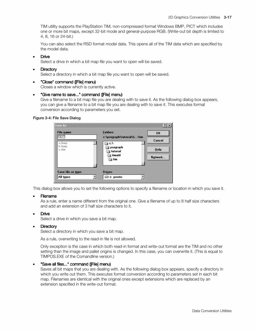
2D Graphics Conversion Utilities 3-17
Printed:11/19/98 4:16 PM By:SCEA Filename:final44Dataconv.doc Last saved by:SONY On:11/19/98 3:28 PM Comments: Master Copy, TechRef Release 4.3.
Data Conversion Utilities
TIM utility supports the PlayStation TIM, non-compressed format Windows BMP, PICT which includesone or more bit maps, except 32-bit mode and general-purpose RGB. (Write-out bit depth is limited to4, 8, 16 or 24-bit.)
You can also select the RSD format model data. This opens all of the TIM data which are specified bythe model data.
x DriveDriveDriveDriveSelect a drive in which a bit map file you want to open will be saved.
x DirectoryDirectoryDirectoryDirectorySelect a directory in which a bit map file you want to open will be saved.
x "Close" command ([File] menu)"Close" command ([File] menu)"Close" command ([File] menu)"Close" command ([File] menu)Closes a window which is currently active.
x "Give name to save..." command ([File] menu)"Give name to save..." command ([File] menu)"Give name to save..." command ([File] menu)"Give name to save..." command ([File] menu)Give a filename to a bit map file you are dealing with to save it. As the following dialog box appears,you can give a filename to a bit map file you are dealing with to save it. This executes formatconversion according to parameters you set.
Figure 3-4: File Save Dialog
This dialog box allows you to set the following options to specify a filename or location in which you save it.
x FilenameFilenameFilenameFilenameAs a rule, enter a name different from the original one. Give a filename of up to 8 half size charactersand add an extension of 3 half size characters to it.
x DriveDriveDriveDriveSelect a drive in which you save a bit map.
x DirectoryDirectoryDirectoryDirectorySelect a directory in which you save a bit map.
As a rule, overwriting to the read-in file is not allowed.
Only exception is the case in which both read-in format and write-out format are the TIM and no othersetting than the image and pallet origins is changed. In this case, you can overwrite it. (This is equal toTIMPOS.EXE of the Comandline version.)
x "Save all files..." command ([File] menu)"Save all files..." command ([File] menu)"Save all files..." command ([File] menu)"Save all files..." command ([File] menu)Saves all bit maps that you are dealing with. As the following dialog box appears, specify a directory inwhich you write out them. This executes format conversion according to parameters set in each bitmap. Filenames are identical with the original ones except extensions which are replaced by anextension specified in the write-out format.

3-18 2D Graphics Conversion Utilities
Printed:11/19/98 4:16 PM By:SCEA Filename:final44Dataconv.doc Last saved by:SONY On:11/19/98 3:28 PM Comments: Master Copy, TechRef Release 4.3.
Data Conversion Utilities
Figure 3-5: Directory Select Dialog
This dialog allows you to set the following options to specify locations in which you save bit maps.
x DriveDriveDriveDriveSelect a drive in which you save bit maps.
x DirectoryDirectoryDirectoryDirectorySelect a directory in which you save bit maps.
As a rule, overwriting to the read-in files is not allowed.
If any write-out file conflicts with the rule, it causes an error and no conversion is executed at all.
x "Set..." command ([File] menu)"Set..." command ([File] menu)"Set..." command ([File] menu)"Set..." command ([File] menu)Sets parameter initial values which will be set in the Parameter Setting window when you will open afile.
Figure 3-6: Set Dialog
If "Subject to read-in file" is set in "Read-in format", a format which was judged from contents of the read-infile is set in the read-in format of the Parameter Setting window. If "RGB" is set, any file is set to the RGB.This also applies to the "Bit depth".
"Image origin" and "Pallet origin" are used as default values for conversion parameters when "TIMinformation priority" is not selected or when read-in format is any other format than the TIM.
For "Write-out pallet", you can select a write-out pallet from the write-out pallet list when a TIM file withmultiple pallets (CLUT) is read in. Determine the default.
Selection of "First one" selects only No. 0 pallet. Selection of "Select all" selects all pallets as write-outpallet. The "Write-out pallet" is provided with another button, "Reflect on origin". This button sets whetherthe pallet origin is automatically set or not when an entry is selected from the write-out pallet list. If this is

2D Graphics Conversion Utilities 3-19
Printed:11/19/98 4:16 PM By:SCEA Filename:final44Dataconv.doc Last saved by:SONY On:11/19/98 3:28 PM Comments: Master Copy, TechRef Release 4.3.
Data Conversion Utilities
set, selection of No. 0 entry from the write-out pallet list sets the pallet origin which is set in the original TIMfile for the pallet origin. Selection of No. 1 entry adds 1 to Y coordinate of the pallet origin which is set in theoriginal TIM file and sets the value for the pallet origin.
Other parameter values than mentioned above are simply used as the initial values in the Parameter Settingwindow.
Values set in the dialog will be saved at end of TIM utility.
"TIM Locate..." command ([Window] menu)Opens "TIM Locate" dialog to locate graphically a TIM format file which is opened in the VRAM.
Figure 3-7: TIM Locate Dialog
"TIM Locate" dialog has, to divide roughly, 4 main areas shown below:
1. VRAM image area
2. Information area
3. Select list area
4. Menu bar
Figure 3-8: VRAM Image Area
This area displays the VRAM image on PlayStation. Rectangles which show image or pallet (CLUT) of thecurrently opened TIM file, a rectangle which shows a range which is displayed and texture page borderlineswhich are referred to for location are displayed. For image or pallet rectangle, the part which does notoverlap with another image or pallet rectangle or the range rectangle is displayed in green and the partwhich overlaps with other rectangles or projects from the VRAM area is displayed in red. The left button ofthe mouse allows you to select these rectangles and you can move them by dragging. Use of the left

3-20 2D Graphics Conversion Utilities
Printed:11/19/98 4:16 PM By:SCEA Filename:final44Dataconv.doc Last saved by:SONY On:11/19/98 3:28 PM Comments: Master Copy, TechRef Release 4.3.
Data Conversion Utilities
button of the mouse while pressing the Shift key or Ctrl key allows you to select multiple image or palletrectangles. Rectangles you select are displayed in blue.
Figure 3-9: Information Area
This area displays information about selected image or pallet rectangle. Image or pallet origin coordinates, aVRAM range the rectangle occupies, a filename and the bit depth are displayed.
You can change the origin coordinates by clicking Up and Down arrow buttons or entering directly numericvalues in the text part. This area displays nothing when multiple image or pallet rectangles are selected.
Figure 3-10: Select List Area
The Select list area displays a list of images and pallets which can be dealt with. This list allows you toselect image or pallet rectangles. Rectangle which was selected in the VRAM image area is regarded to beselected also in the list. Use of the Shift or Ctrl key allows you to select multiple rectangles. Dragging alsoallows selection of multiple rectangles.
Figure 3-11: Menu Bar
Sorting menux TextureTextureTextureTexture
Sets the left top corner of all textures to a side of the nearest texture area or display range. Selection ofthis menu after setting roughly textures with the mouse arranges them orderly.
x PalletPalletPalletPalletPaves all pallets vertically from the bottom of a range which is currently displayed.
Grid menux NonNonNonNon
Disables grid function. Texture is located to coordinates you specified with the mouse.
x Texture pageTexture pageTexture pageTexture pageMoves and lines up textures along the nearest texture page borderline from coordinates you specifiedwith the mouse.
Both X and Y coordinates are lined up along the texture page borderline if you selected "XY", only Xcoordinates are lined up if you selected "X" and only Y coordinates are lined up if you selected "Y".
x MagnetMagnetMagnetMagnetMoves and sets textures to a side of the nearest texture area or display range from coordinates youspecified with the mouse. Both X and Y coordinates are lined up along the texture page borderline ifyou selected "XY", only X coordinates are lined up if you selected "X" and only Y coordinates are linedup if you selected "Y".
Zoom menuSets scales for the image display in the "VRAM image area". Use this for small texture, pallet and otherswhen it is difficult to select or move them with ordinary scales.

2D Graphics Conversion Utilities 3-21
Printed:11/19/98 4:16 PM By:SCEA Filename:final44Dataconv.doc Last saved by:SONY On:11/19/98 3:28 PM Comments: Master Copy, TechRef Release 4.3.
Data Conversion Utilities
Display range menuChanges display resolutions which are actually used on PlayStation. Change of the display range changesthe range of the display area.
Press "OK" button to reflect edited VRAM images on the Parameter Setting window. Selection of "Cancel"button or "Close" of the system menu invalidates move of image or pallet.
Remarks
The compressed format BMP, JPEG compressed PICT, 32-bit PICT and PICT without bit map cannot beread in.
Write-out as the compressed format BMP or JPEG compressed format PICT file is not allowed.
Write-out file bit depth is limited to 4, 8, 16 or 24-bit.
In data conversion in which the bit depth reduces, for example, from 16-bit to 8-bit, color information isapproximated. As this approximation is not realized with a method such as color compression but withcolor map on which R, G and B are uniformly allocated, the color accuracy may deteriorate.
As a rule, overwriting to the file which was read in is not allowed. However, overwriting is allowed whenboth read-in format and write-out format are the TIM and only image origin and pallet origin were changed.This function is equal to TIMPOS.EXE of Commandline version.

3-22 2D Graphics Conversion Utilities
Printed:11/19/98 4:16 PM By:SCEA Filename:final44Dataconv.doc Last saved by:SONY On:11/19/98 3:28 PM Comments: Master Copy, TechRef Release 4.3.
Data Conversion Utilities
TIMEXP: Plug-in for use with Photoshop 2.5 and 3.0
Version 1.2
Documentation date: 11/18/97
Description
FeaturesTIMEXP.8BE is a plug-in module which allows you to output image which is created and amended withAdobe Photoshop to DTL-H201A and view it on a video monitor. With this, you can check how the imagedata is displayed on the PlayStation system.
This software has the following features:
x Supports 4 color modesThe software supports all image data modes (4/8-bit CLUT and 16/24-bit Direct) that the PlayStationsystem can deal with.
x Supports 8 display modesThe software supports all display modes that the PlayStation system can deal with. Change of theVRAM display start address allows you to display any VRAM area.
x Allows you to specify the VRAM locationThe software allows you to load the Display area, Texture page and Texture CLUT to any VRAMaddress. With this, you can also turn on/off Texture mapping to the Display area.
x Supports the transparent control bit (partly)The software provides you with a function to use the transparent control bit (STP) unique to thePlayStation system.
Operating requirementTIMEXP.8BE is subject to the Adobe Photoshop operating requirement because it is a module which isstarted up from Adobe Photoshop. General matters of Adobe Photoshop are not explained here becausethis manual is written for those who are familiar to its operating procedure. For details of Adobe Photoshop,refer to instruction manuals and others attached to Adobe Photoshop.
System configurationSystem configurationSystem configurationSystem configuration
In order to use TIMEXP.8BE, the following software is required:
Adobe Photoshop 2.5J or 3.0
Preparation
Installation of programFor use with Adobe Photoshop 2.5: Copy TIMEXP.8BE at C:\PSXGRAPH\BIN to PLUGINS subdirectory ina directory in which PHOTOSHP.EXE was installed.
For use with Adobe Photoshop 3.0: Copy into subdirectory PLUGINS\EXPORT.
Setup of operating environmentStart up ABOARD.EXE, a tool for setting the DTL-H201A board address and set the DTL-H201A address.
Check of installation and setupStarting up Adobe Photoshop and selecting "HELP/ABOUT PLUG-IN/TIM DISPLAY..." option from theMenu bar to open the About box allows you to check the address which is set. (The default address is0x1340.)

2D Graphics Conversion Utilities 3-23
Printed:11/19/98 4:16 PM By:SCEA Filename:final44Dataconv.doc Last saved by:SONY On:11/19/98 3:28 PM Comments: Master Copy, TechRef Release 4.3.
Data Conversion Utilities
Operations
In order to view the Adobe Photoshop image on DTL-H201ASelect a window you want to access and then output the Adobe Photoshop image information to DTL-H201A with "TIM DISPLAY..." command to view it on the display.
How to use "TIM DISPLAY..." command1. Select "OUTPUT PLUG/TIM DISPLAY..." option from the file menu to access the TIM Export Options
dialog box.
Figure 3-12: TIM Export Options Dialog Box
2. Set or select any desired value for the following settings and click "OK".
x Color modeColor modeColor modeColor modeSet a DTL-H201A pixel format. One of the following formats is available, depending on the AdobePhotoshop image mode.
Index color o 4 or 8-bit CLUT
RGB color o 16 or 24-bit Direct
x Display modeDisplay modeDisplay modeDisplay modeSet the DTL-H201A horizontal (W) and vertical (H) resolutions. Change of the start address allowsyou to begin with any VRAM address you want to display (left top corner)
x Display areaDisplay areaDisplay areaDisplay areaSet a rectangular VRAM address (left top corner) to map the texture data and the width and height.This is invalid in Load only mode.
x Texture pageTexture pageTexture pageTexture pageSet a VRAM address (left top corner) to store the texture data and the width and height. In Loadonly mode, the address is automatically set to (0,0).
x Texture CLUTTexture CLUTTexture CLUTTexture CLUTSet a VRAM address (left top corner) to place the CLUT. This is invalid when the color mode is16/24-bit.

3-24 2D Graphics Conversion Utilities
Printed:11/19/98 4:16 PM By:SCEA Filename:final44Dataconv.doc Last saved by:SONY On:11/19/98 3:28 PM Comments: Master Copy, TechRef Release 4.3.
Data Conversion Utilities
x Letting any other color than the black turn semitransparentLetting any other color than the black turn semitransparentLetting any other color than the black turn semitransparentLetting any other color than the black turn semitransparentIn order to let a color turn semitransparent, set an Adobe Photoshop format pixel which has avalue of 8 or more for at least one of R, G and B or transparent control bit which is CULT entry.
x Letting the black turn transparentLetting the black turn transparentLetting the black turn transparentLetting the black turn transparentIn order to let the black turn transparent, clear any Adobe Photoshop format pixel which has valuesof 7 or less for all of R, G and B or transparent control bit which is CULT entry.
x Load onlyLoad onlyLoad onlyLoad onlyChanges the system mode to Load only mode. This mode merely sends the texture data to theVRAM. It does not map it into a rectangle of display area. Therefore, the transparent control isinvalid. Selection of the 24-bit color mode sets automatically this mode.
x Screen clearScreen clearScreen clearScreen clearClears the whole VRAM before drawing.
x CancelCancelCancelCancelCancels drawing.
x OKOKOKOKOutputs the drawing command to DTL-H201A.
Note
In the Adobe Photoshop format, components R, G and B have 8-bit resolution. On the other hand, eachresolution of DTL-H201A is 5-bit, except 24-bit mode. Therefore, outputted to DTL-H201A, 5 high orderbits are valid but 3 low order bits are ignored unconditionally.
For example:
Adobe Photoshop DTL-H201A internal notation
R, G, B):(0x08, 0x07, 0xff) o [0x01, 0x00, 0x1f]
DTL-H201A is provided with the transparent control bit (except 24-bit mode) but Adobe Photoshop hasnothing which corresponds to it. This module is provided with 2 types of check box to deal with thetransparent control bit. These boxes allow you to use the transparent control bit to some degree. However,"transparent" and "(semi) nontransparent black" cannot be mapped into a display area at a time. In suchcase, use (R, G, B)=(0, 0, 8) and others instead of "black".
The transparent control bit is valid only when texture is mapped into the display area.

2D Graphics Conversion Utilities 3-25
Printed:11/19/98 4:16 PM By:SCEA Filename:final44Dataconv.doc Last saved by:SONY On:11/19/98 3:28 PM Comments: Master Copy, TechRef Release 4.3.
Data Conversion Utilities
TIMexpE: Plug-in for use with Photoshop 4.0, Windows or Artist Board
Version 4.0E
Documentation date: 8/29/97
Description
FeaturesTIMexpE.8BE is a plug-in module for Adobe Photoshop 4.0 which allows you to output an image which iscreated and modified in Adobe Photoshop 4.0 to the Artist Board and view it on a video monitor. With this,you can check how the image data is displayed on the PlayStation system.
This software has the following features:
x Supports 4 color modesThe software supports all image data modes (4/8-bit CLUT and 16/24-bit Direct) that the PlayStationsystem deals with.
x Supports 8 display modesThe software supports all display modes that the PlayStation system deals with. Change of the VRAMdisplay start address allows you to display any VRAM area.
x Allows you to specify the VRAM locationThe software allows you to load the Display area, Texture page and Texture CLUT to any VRAMaddress. With this, you can also turn on/off Texture mapping to the Display area.
The software provides you with a function to use the transparent control bit (STP) unique to thePlayStation system.
Operating requirementTIMexpE.8BE is subject to Adobe Photoshop operating requirements because it is a module which isstarted up from Adobe Photoshop. General matters of Adobe Photoshop are not explained here becausethis manual is written for those who are familiar with its operating procedures. For details about AdobePhotoshop, refer to instruction manuals and other information attached to Adobe Photoshop.
System configurationTIMexpE.8BE requires the following operating environment:
Adobe Photoshop 4.0, Windows 95, PlayStation Artist Board
Preparation
Installation of programCopy TIMexpETIMexpETIMexpETIMexpE.8BE.8BE.8BE.8BE into the PLUGINS\EXPORT subdirectory of the Photoshop directory. Copy theinitialization file TIMexp.iniTIMexp.iniTIMexp.iniTIMexp.ini into the system directory C:\Windows.
Setup of operating environmentStart up ABOARD.EXE, a tool for setting the Artist Board address, and set the address.
Setup of initialization file “TIMexp.ini”This file is located in the system directory and includes some program settings as below:

3-26 2D Graphics Conversion Utilities
Printed:11/19/98 4:16 PM By:SCEA Filename:final44Dataconv.doc Last saved by:SONY On:11/19/98 3:28 PM Comments: Master Copy, TechRef Release 4.3.
Data Conversion Utilities
Default valuesWhole default values of the Export Options dialog box can be customized by editing the [DefaultValue]section. See Table 3-1 for more details.
Record masksWhen you record actions, plug-ins will output whole parameters. Although this export plug-in contains 26parameters, a few parameters may be changed in most cases. Setting a parameter at 1 in the[RecordMask] section allows you to disable a parameter output which you did not change and therefore donot have to notice.
In order to record actions with more flexibility, use fewer parameters. The record mask is a useful functionfor reducing the number of parameters used to a minimum.
The values of maskable parameters are almost the same as the default values. The exception "Base" is anon-maskable parameter. See the initial file for more details.
List of saved valuesA list of whole parameter values is needed to export an image. When you click the "Save" button in theExport Options dialog box, the plug-in will immediately generate / update the list associated with the fullpath of the target image file.
The list consists of 26 parameters in the following order:
Color,DispModeH, DispModeV, DispStartX, DispStartY,DispAreaX, DispAreaY, DispAreaW, DispAreaH,TexX, TexY, TexW, TexH,ClutX, ClutY,ABR, Lower3, StpOthers, StpBlack, LoadOnly, ClearScreen,ColorAuto, TexAddrAuto, TexSizeAuto, ClutAddrAuto, StpBitAuto

2D Graphics Conversion Utilities 3-27
Printed:11/19/98 4:16 PM By:SCEA Filename:final44Dataconv.doc Last saved by:SONY On:11/19/98 3:28 PM Comments: Master Copy, TechRef Release 4.3.
Data Conversion Utilities
Table 3-1: Parameters specifiable in the [DefaultValue] section of TIMexp.ini
Entry name Content
Base(0) Base setting (0: Default values, 1: Previously saved values)ColorAuto(0) Automatic Color mode (0: Off, 1: Auto)Indexed(1) Color mode for Indexed color (0: 4 bit CLUT, 1: 8 bit CLUT)Direct(2) Color mode for RGB color (2: 16 bit Direct, 3: 24 bit Direct)DispModeH(0) Horizontal screen resolution (0: 256, 1: 320, 2: 512, 3: 640)DispModeV(0) Vertical screen resolution (0: 240, 1: 480)DispStartX(0) Display start address: XDispStartY(0) Display start address: YDispAreaX(0) X Address of display areaDispAreaY(0) Y Address of display areaDispAreaW(1) Width of display areaDispAreaH(1) Height of display areaTexAddrAuto(0) Automatic texture address (0: Off, 1: Auto)TexX(0) X Address of textureTexY(0) Y Address of textureTexSizeAuto(1) Automatic texture size (0: Off, 1: Auto)TexW(1) Width of texture sizeTexH(1) Height of texture sizeClutAddrAuto(0) Automatic CLUT address (0: Off, 1: Auto)ClutX(0) X Address of CLUTClutY(0) Y Address of CLUTABR(0) Translucent rate (0 is compatible with TIMEXP version 1.2E)
0: Foreground: 50% + Background: 50%1: Foreground: 100% + Background:100%2: Foreground:-100% + Background:100%3: Foreground: 25% + Background:100%
Lower3(0) Rounding method (0 is compatible with TIMEXP version 1.2E)0: round down, 1: round off, 2: round up
StpBitAuto(0) Automatic STP bit control (0: Off, 1: Auto)StpOthers(0) Except black -> Translucent (0: Off, 1: On)StpBlack(0) Black -> Transparent (0: Off, 1: On)LoadOnly(0) Load Only (0: Off, 1: On)ClearScreen(0) Clear screen initially (0: Off, 1: On)WnNotSaved(1) Warn of "Saved values not found" (0: Silent, 1: Warn)WnModeDisagree(1) Warn of "Color mode disagreement" (0: Silent, 1: Warn)ReadIniFile(0) Read initial file (0: Once at initial call, 1: At every call)
Caution: An entry name prefixed with ';' is ignored and the plug-in adopts the value inparentheses.
How the TIM format plugin works with the TIM export plug-inWhen the TIM format plug-in TIMfmtETIMfmtETIMfmtETIMfmtE.8bi.8bi.8bi.8bi opens a TIM file, it always scans the file header and the contentsof the CLUT and texture image data in order to check on STP bit, and writes the result into Caption sectionof Photoshop’s File Information data field. If the Caption is valid and the color mode agrees with the targetimage, then the export plug-in can enable four "Auto" check-boxes: "Color mode", "Texture Pageaddress", "Texture CLUT address" and "STP bit". These check-boxes will be disabled when the Caption isincorrect.
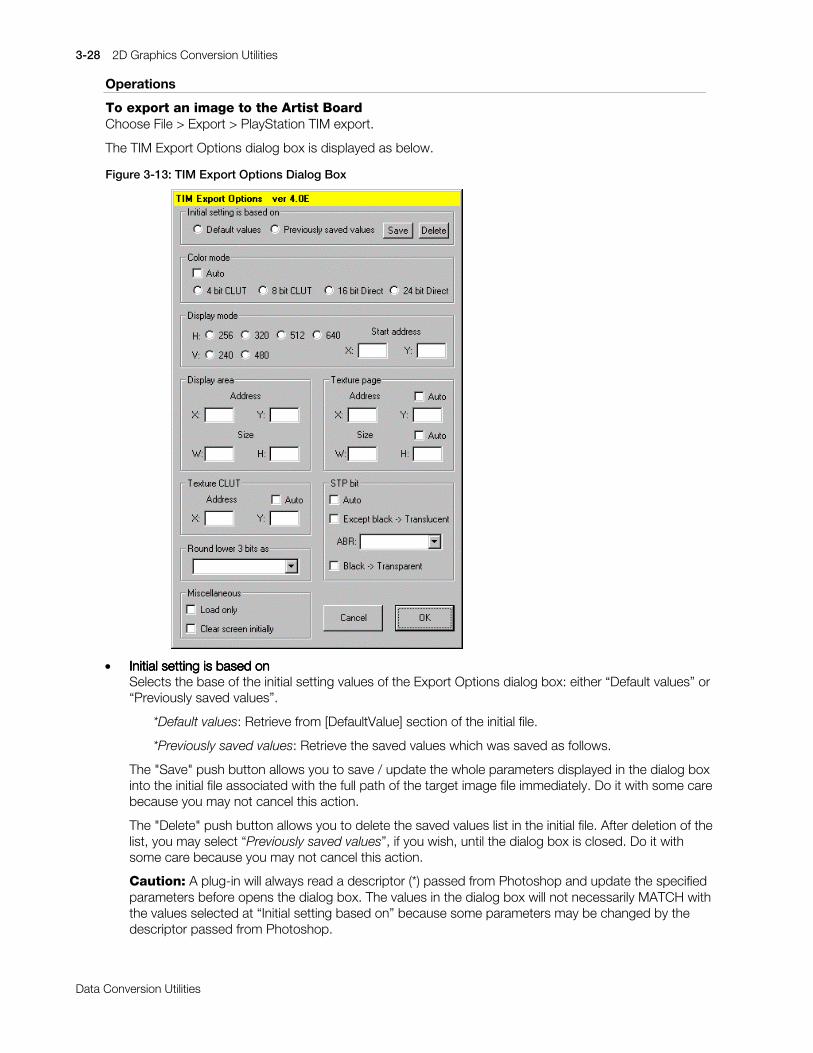
3-28 2D Graphics Conversion Utilities
Printed:11/19/98 4:16 PM By:SCEA Filename:final44Dataconv.doc Last saved by:SONY On:11/19/98 3:28 PM Comments: Master Copy, TechRef Release 4.3.
Data Conversion Utilities
Operations
To export an image to the Artist BoardChoose File > Export > PlayStation TIM export.
The TIM Export Options dialog box is displayed as below.
Figure 3-13: TIM Export Options Dialog Box
x Initial setting is based onInitial setting is based onInitial setting is based onInitial setting is based onSelects the base of the initial setting values of the Export Options dialog box: either “Default values” or“Previously saved values”.
*Default values: Retrieve from [DefaultValue] section of the initial file.
*Previously saved values: Retrieve the saved values which was saved as follows.
The "Save" push button allows you to save / update the whole parameters displayed in the dialog boxinto the initial file associated with the full path of the target image file immediately. Do it with some carebecause you may not cancel this action.
The "Delete" push button allows you to delete the saved values list in the initial file. After deletion of thelist, you may select “Previously saved values”, if you wish, until the dialog box is closed. Do it withsome care because you may not cancel this action.
Caution: A plug-in will always read a descriptor (*) passed from Photoshop and update the specifiedparameters before opens the dialog box. The values in the dialog box will not necessarily MATCH withthe values selected at “Initial setting based on” because some parameters may be changed by thedescriptor passed from Photoshop.

2D Graphics Conversion Utilities 3-29
Printed:11/19/98 4:16 PM By:SCEA Filename:final44Dataconv.doc Last saved by:SONY On:11/19/98 3:28 PM Comments: Master Copy, TechRef Release 4.3.
Data Conversion Utilities
When you set all parameters in the [RecordMask] section and record an export action commandwithout changing any parameters, the plug-in will record a command with “Based on” parameters only.This command allows you to export a image with the original settings as you specified.
*: A descriptor is a component of a command for an action, and is a pair of data values in the form of[key value] that describe a property of an object or the parameters of an event.
x Color modeColor modeColor modeColor modeSets the pixel format to be used with the Artist Board. Choose one of the following settings accordingto the image mode:
Indexed color: 4 bit CLUT or 8 bit CLUT
RGB color: 16 bit Direct or 24 bit Direct
x Display modeDisplay modeDisplay modeDisplay modeSets the horizontal (H) and vertical (V) resolution of the Artist Board screen. By entering a start address,you can see any area of VRAM.
x Display areaDisplay areaDisplay areaDisplay areaSets the address in VRAM (from the upper left corner) and the width and height of the rectangle to betexture-mapped. These are disabled in the Load Only mode.
x Texture pageTexture pageTexture pageTexture pageSets the address in VRAM (from the upper left corner) and the width and height of the texture data. Thewidth and height provided by Photoshop are available by clicking "Auto".
The address is automatically set to (0, 0) in the Load Only mode.
x Texture CLUTTexture CLUTTexture CLUTTexture CLUTSets the address in VRAM (from the upper left corner) of the CLUT. These parameters are disabledwhen the color mode is set to 16 bit Direct or 24 bit Direct.
x STPSTPSTPSTP bit bit bit bitSTP bit settings are enabled except in the Load Only mode.
* Except black -> Translucent
Sets the transparency control bit for pixels or CLUT entries, other than those where the (R, G, B)values are set to (0, 0, 0) after 8 bit to 5 bit conversion. As a result, all colors other than blackbecome translucent only in translucent mode.
* ABR
When you check the check box of "Except black -> Translucent", you can select the rate oftranslucence as below:
1) Foreground: 50% + Background: 50% (compatible with version 1.2E)
2) Foreground: 100% + Background: 100%
3) Foreground: -100% + Background: 100%
4) Foreground: 25% + Background: 100%
* Black -> Transparent
Clears the transparency control bit for those pixels or CLUT entries where the (R, G, B) values areset to (0, 0, 0) after 8 bit to 5 bit conversion. As a result, black becomes transparent, regardless oftranslucency mode.

3-30 2D Graphics Conversion Utilities
Printed:11/19/98 4:16 PM By:SCEA Filename:final44Dataconv.doc Last saved by:SONY On:11/19/98 3:28 PM Comments: Master Copy, TechRef Release 4.3.
Data Conversion Utilities
x Round lower 3 bits asRound lower 3 bits asRound lower 3 bits asRound lower 3 bits asIn Photoshop, RGB components are represented in a resolution of 8 bits for each color, but the ArtistBoard supports only 5 bits for each (except in the 24 bit Direct mode). Therefore, a transformation from8 bits to 5 bits is required when exporting image data. This export plug-in lets you select thetransformation method from the options given here:
1) 00000.XXX > 00000 round down unconditionally (compatible with TIMEXP version 1.2E)
2) 00000.1XX > 00001 round up if Bit2 is 1 (here Bit0 is the LSB)
3) 00000.XXX > 00001 round up unconditionally
x MiscellaneousMiscellaneousMiscellaneousMiscellaneous* Load Only
Sets the Load Only mode. In this mode, texture data only is sent to VRAM, and mapping of thedisplay area is not performed. Transparency control bits are therefore ignored. This mode isautomatically selected when the color mode is set to 24 bit Direct.
* Clear screen initially
Clears VRAM before exporting image data.
x CancelCancelCancelCancelCancels drawing and keeps parameter values unchanged for recording an action again.
x OKOKOKOKExports image data to the Artist Board.
Notes
A method of setting the contents displayed in Export Options dialog boxThe contents displayed in the Export Options dialog box are set as shown below:
1. If you set "Base=1" (previously saved values) in the [DefaultValue] section of the initial file, then thisplug-in will attempt to find the saved values list and set them. The default values will be used if thesearch fails, or there is color mode disagreement (*) occurs, or "Base=0" is set.
*: The color mode specified in the descriptor or the saved values list disagrees with the color mode ofthe target image data.
2. If Photoshop passes the plug-in a descriptor, continue reading below. Otherwise go to 4.
First, the plug-in will check the color mode. If the color mode specified in the descriptor agrees with thetarget image data, then the plug-in changes the parameters specified in the descriptor. Otherwise thedescriptor will be discarded.
3. If the descriptor sets "Base=1", then the plug-in attempts to find the list of saved values and set them.The default values will be used if the search fails or the color mode disagreement occurs, or "Base=0"is set.
4. "Auto" check-boxes will become effective at this stage, if possible.
5.... The dialog box will be opened.
Caution: When this plug-in finishes exporting an image normally, whole parameters are passed toPhotoshop as a descriptor. Photoshop keeps this descriptor, and passes it back to this plug-in on re-invocation. Therefore, some warnings below may appear when receiving a preceding descriptor.
x * * * * Color mode disagreement in the correct operations:
When you export an RGB color image after exporting another indexed color image with “Color mode: 8bit CLUT”, on the condition that the plug-in outputs the color mode descriptor by setting “Color=0” inthe [RecordMask] section of the initial file, Photoshop passes a descriptor of “Color mode: 8 bit CLUT”to the plug-in. In this case, a color mode disagreement will occur.

2D Graphics Conversion Utilities 3-31
Printed:11/19/98 4:16 PM By:SCEA Filename:final44Dataconv.doc Last saved by:SONY On:11/19/98 3:28 PM Comments: Master Copy, TechRef Release 4.3.
Data Conversion Utilities
x **** Unexpected changes of parameters:
For example, on the condition of “Base = 0 (Default values)” in the initial file, when you export an imagewithout saved values after exporting another image with “Based on: saved values”, the plug-in will warnyou “No saved values found”, because Photoshop passes the plug-in a descriptor of “Based on: savedvalues”.
No descriptor will be passed to Photoshop if you cancel an export operation.
Important PointsTransparency control bits are only valid in the display area where texture mapping is drawn.
You cannot perform mapping in a single display area using both "Transparent" and "Translucent exceptblack" attributes at the same time. For situations such as this, set all "black" pixels to an alternate value,such as (R, G, B) = (0, 0, 1), in the TIM format.

3-32 2D Graphics Conversion Utilities
Printed:11/19/98 4:16 PM By:SCEA Filename:final44Dataconv.doc Last saved by:SONY On:11/19/98 3:28 PM Comments: Master Copy, TechRef Release 4.3.
Data Conversion Utilities
TIMfmtE: Plug-in for use with Photoshop 4.0, Windows 95 or NT
Version 4.0(E)
Documentation date: 8/29/97
Description
TIMfmtE.8BI is a plug-in module for Adobe Photoshop 4.0, which allows you to import directly intoPhotoshop two dimensional TIM format files that the PlayStation system deals with, and to output imagescreated with Photoshop into TIM format files.
This software has the following features:
x Supports 4 TIM format modesThe software supports all image data modes (4/8-bit CLUT and 16/24-bit Direct) that PlayStationsystem deals with.
x Supports the transparency control bitThe software allows you to use the transparent control bit (STP) to save the image data as a TIMformat file.
x Allows you to specify the VRAM load addressThe software allows you to specify Texture CLUT and Texture page addresses to load image data,saved as a TIM format file, to the VRAM.
Operating requirementTIMFMT.8BI is subject to the Adobe Photoshop operating requirement because it is a module which isstarted up from Adobe Photoshop. General matters of Adobe Photoshop are not explained here becausethis manual is written for those who are familiar to its operating procedure. For details of Adobe Photoshop,refer to instruction manuals and other information attached to Adobe Photoshop.
System configurationTIMfmtE.8BI requires the following operating environment.
Adobe Photoshop 4.0, Windows 95 or NT
Preparation
Installation of programCopy TIMfmtETIMfmtETIMfmtETIMfmtE.8BE.8BE.8BE.8BE into the PLUGINS\FORMAT subdirectory of the Photoshop directory. Copy theinitialization file TIMTIMTIMTIMfmt.inifmt.inifmt.inifmt.ini into the system directory C:\Windows.
Setup of initialization file “TIMfmt.ini”This file is located in the system directory and includes some program settings as below:
Default valuesWhen you save a new image or one from another format as a TIM file, there is no File Information to bereferred to. In this case, this plug-in will refer to the [DefaultValue] section of the initial file. See Table 3-2 formore details.
Record masksWhen you record actions, plug-ins will output whole parameters. Although this file format plug-in contains15 parameters, a few parameters may be changed in most cases. Setting a parameter at 1 in the[RecordMask] section allows you to disable a parameter output which you did not change and therefore donot have to notice.
In order to record actions with more flexibility, use fewer parameters. The record mask is a useful functionfor reducing the number of parameters used to a minimum.
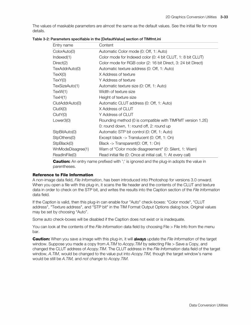
2D Graphics Conversion Utilities 3-33
Printed:11/19/98 4:16 PM By:SCEA Filename:final44Dataconv.doc Last saved by:SONY On:11/19/98 3:28 PM Comments: Master Copy, TechRef Release 4.3.
Data Conversion Utilities
The values of maskable parameters are almost the same as the default values. See the initial file for moredetails.
Table 3-2: Parameters specifiable in the [DefaultValue] section of TIMfmt.ini
Entry name Content
ColorAuto(0) Automatic Color mode (0: Off, 1: Auto)Indexed(1) Color mode for Indexed color (0: 4 bit CLUT, 1: 8 bit CLUT)Direct(2) Color mode for RGB color (2: 16 bit Direct, 3: 24 bit Direct)TexAddrAuto(0) Automatic texture address (0: Off, 1: Auto)TexX(0) X Address of textureTexY(0) Y Address of textureTexSizeAuto(1) Automatic texture size (0: Off, 1: Auto)TexW(1) Width of texture sizeTexH(1) Height of texture sizeClutAddrAuto(0) Automatic CLUT address (0: Off, 1: Auto)ClutX(0) X Address of CLUTClutY(0) Y Address of CLUTLower3(0) Rounding method (0 is compatible with TIMFMT version 1.2E)
0: round down, 1: round off, 2: round upStpBitAuto(0) Automatic STP bit control (0: Off, 1: Auto)StpOthers(0) Except black -> Translucent (0: Off, 1: On)StpBlack(0) Black -> Transparent(0: Off, 1: On)WnModeDisagree(1) Warn of "Color mode disagreement" (0: Silent, 1: Warn)ReadIniFile(0) Read initial file (0: Once at initial call, 1: At every call)
Caution: An entry name prefixed with ';' is ignored and the plug-in adopts the value inparentheses.
Reference to File InformationA non-image data field, File Information, has been introduced into Photoshop for versions 3.0 onward.When you open a file with this plug-in, it scans the file header and the contents of the CLUT and texturedata in order to check on the STP bit, and writes the results into the Caption section of the File Informationdata field.
If the Caption is valid, then this plug-in can enable four "Auto" check-boxes: "Color mode", "CLUTaddress", "Texture address", and "STP bit" in the TIM Format Output Options dialog box. Original valuesmay be set by choosing “Auto”.
Some auto check-boxes will be disabled if the Caption does not exist or is inadequate.
You can look at the contents of the File Information data field by choosing File > File Info from the menubar.
Caution: When you save a image with this plug-in, it will alwaysalwaysalwaysalways update the File Information of the targetwindow. Suppose you made a copy from A.TIM to Acopy.TIM by selecting File > Save a Copy, andchanged the CLUT address of Acopy.TIM. The CLUT address in the File Information data field of the targetwindow, A.TIM, would be changed to the value put into Acopy.TIM, though the target window’s namewould be still be A.TIM, and not change to Acopy.TIM.

3-34 2D Graphics Conversion Utilities
Printed:11/19/98 4:16 PM By:SCEA Filename:final44Dataconv.doc Last saved by:SONY On:11/19/98 3:28 PM Comments: Master Copy, TechRef Release 4.3.
Data Conversion Utilities
Operations
To open a TIM fileChoose File > Open, and select a TIM format file.
To save a file in TIM file format1. In the "Save" or "Save As" dialog box, select " PlayStation TIM (*.TIM)" from the "File Format" list.
2. Type a file name, and click "Save".
3. The TIM Format Output Options dialog box is displayed as below:
Figure 3-14: TIM Format Output Options Dialog Box
x Color modeColor modeColor modeColor modeChoose one of the following settings according to the color mode of the image:
Indexed color: 4 bit CLUT or 8 bit CLUTRGB color: 16 bit Direct or 24 bit Direct
x CLUTCLUTCLUTCLUT section section section sectionSets the address in VRAM (from the upper left corner) of the CLUT. The size fields are filled inautomatically.
x Pixel data sectionPixel data sectionPixel data sectionPixel data sectionSets the address in VRAM (from the upper left corner) and the width and height of the textureimage data. The sizes provided by Photoshop are usually available, and are used by clicking“Auto".
x Round lower 3 bits asRound lower 3 bits asRound lower 3 bits asRound lower 3 bits asIn Photoshop, RGB components are represented in a resolution of 8 bits for each color, but TIMformat supports only 5 bits for each (except in the 24 bit Direct mode). Therefore, a transformationfrom 8 bits to 5 bits is required when saving image data. This format plug-in lets you select thetransformation method from the options given here:
1) 00000.XXX > 00000 round down unconditionally (compatible with TIMFMT version 1.2E)2) 00000.1XX > 00001 round up if Bit2 is 1 (here Bit0 is the LSB)3) 00000.XXX > 00001 round up unconditionally

2D Graphics Conversion Utilities 3-35
Printed:11/19/98 4:16 PM By:SCEA Filename:final44Dataconv.doc Last saved by:SONY On:11/19/98 3:28 PM Comments: Master Copy, TechRef Release 4.3.
Data Conversion Utilities
x STPSTPSTPSTP bit bit bit bitSTP bit settings are enabled, except in 24 bit Direct mode.
* Except black -> Translucent
Sets the transparency control bit for pixels or CLUT entries, other than those where the (R, G,B) values are set to (0, 0, 0) after 8 bit to 5 bit conversion. As a result, all colors other thanblack become translucent only in translucent mode.
* Black -> Transparent
Clears the transparency control bit for those pixels or CLUT entries where the (R, G, B) valuesare set to (0, 0, 0) after 8 bit to 5 bit conversion. As a result, black becomes transparent,regardless of translucency mode.
x CancelCancelCancelCancelCancels the save operation and keeps the values the same on recording an action again.
Suppose you save NEW.TIM with the Save As command over OLD.TIM and respond “Yes” to themessage that warned you about replacing an existing file. No change will be made to OLD.TIM bychoosing “Cancel” at this step.
x OKOKOKOKSaves the image data in TIM file format.
Notes
A method of setting the contents displayed in Output Options dialog boxThe contents displayed in the Format Output Options dialog box are set as shown below:
1. The default values in the initial file are adopted as initial setting values.
2. If Photoshop passes the plug-in a descriptor (*1), continue reading below. Otherwise go to 3.
First, the plug-in will check the color mode. If a color mode disagreement (*2) has occurred, then theplug-in will discard the descriptor. Otherwise the plug-in changes the parameters specified in thedescriptor.
*1: A descriptor is a component of a command for an Action, and is a pair of data values in the form of[key value] that describe the property of an object or the parameters of an event.
*2: The color mode specified in the descriptor disagrees with the color mode of target image data.
3. "Auto" check-boxes will become effective at this stage, if possible.
4. The dialog box will be opened.
Caution: When this plug-in finishes saving a file normally, whole parameters are passed to Photoshopas a descriptor. Photoshop keeps this descriptor, and passes it back to this plug-in on re-invocation.Therefore, some warnings below may appear when receiving a preceding descriptor.
For example, when you save an RGB color image after saving another indexed color image with “Colormode: 8 bit CLUT”, on the condition that the plug-in outputs the color mode descriptor by setting“Color=0” in the [RecordMask] section of the initial file, Photoshop passes a descriptor of “Color mode:8 bit CLUT” to this plug-in. In this case, a color mode disagreement will occur.
No descriptor will be handed to Photoshop if you cancel the save operation.
Important PointsYou cannot save a single TIM file which contains both "transparent" and "translucent/non-transparentblack" at the same time. For situations such as this, set all " translucent/non-transparent black" pixels to analternate value such as (R, G, B) = (0, 0, 1) in the TIM format.

3-36 2D Graphics Conversion Utilities
Printed:11/19/98 4:16 PM By:SCEA Filename:final44Dataconv.doc Last saved by:SONY On:11/19/98 3:28 PM Comments: Master Copy, TechRef Release 4.3.
Data Conversion Utilities
RGB components in Photoshop are used at a resolution of 8 bits each, but the TIM format only uses 5 bitsfor each (except in 24 bit Direct mode). Therefore, when a TIM file is opened, 0s will be inserted into thelower 3 bits.
Photoshop's indexed color images use a 256-entry CLUT, so even for 4-bit CLUT, TIM files of up to 256colors may be maintained. However, when the image is displayed in Photoshop, only the first 16 colors willbe used.
2D Graphics Conversion Utilities 3-37
Printed:11/19/98 4:16 PM By:SCEA Filename:final44Dataconv.doc Last saved by:SONY On:11/19/98 3:28 PM Comments: Master Copy, TechRef Release 4.3.
Data Conversion Utilities
TIMFMT/TIMformatE: Plug-ins for use with Photoshop 2.5 and 3.0
Version 1.2 of TIMFMT.8BI
Version 1.3 of TIMformatE.8BI
Documentation date: 11/18/97
Description
These modules allow you to import directly two dimensional TIM format files that the PlayStation systemdeals with into Adobe Photoshop and output images created with Adobe Photoshop into the TIM formatfile.
TIMFMT.8BI is a plug-in module for use with Adobe Photoshop 2.5.
TIMformatE.8BI is for use with Photoshop 3.0.
This software has the following features:
x Supports 4 TIM format modesThe software supports all image data modes (4/8-bit CLUT and 16/24-bit Direct) that PlayStationsystem can deal with.
x Supports the transparent control bit (partly)The software allows you to use the transparent control bit (STP) to save the image data as the TIMformat file.
x Allows you to specify the VRAM load addressThe software allows you to specify Texture CLUT and Texture page addresses to load the image datawhich was saved as the TIM format file to the VRAM.
Operating requirementThe plug-in is subject to the Adobe Photoshop operating requirement because it is a module which isstarted up from Adobe Photoshop. General matters of Adobe Photoshop are not explained here becausethis manual is written for those who are familiar to its operating procedure. For details of Adobe Photoshop,refer to instruction manuals and others attached to Adobe Photoshop.
Preparation
Installation of programAdobe Photoshop 2.5 users:
Copy TIMFMT.8BI to PLUGINS subdirectory in the directory in which PHOTOSHP.EXE is installed.
Adobe Photoshop 3.0 users:
Copy TIMformatE.8BI into the subdirectory PLUGINS\FORMATS.
Operations
In order to open a TIM format file as an Adobe Photoshop document"Open..." command is available to open a document when the file extension of "*.TIM" is attached to a TIMformat file you want to open. Otherwise, use "Open in specified format..." command unless the fileextension of "*.TIM" is attached to.
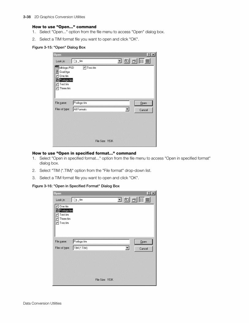
3-38 2D Graphics Conversion Utilities
Printed:11/19/98 4:16 PM By:SCEA Filename:final44Dataconv.doc Last saved by:SONY On:11/19/98 3:28 PM Comments: Master Copy, TechRef Release 4.3.
Data Conversion Utilities
How to use "Open..." command1. Select "Open..." option from the file menu to access "Open" dialog box.
2. Select a TIM format file you want to open and click "OK".
Figure 3-15: "Open" Dialog Box
How to use "Open in specified format..." command1. Select "Open in specified format..." option from the file menu to access "Open in specified format"
dialog box.
2. Select "TIM (*.TIM)" option from the "File format" drop-down list.
3. Select a TIM format file you want to open and click "OK".
Figure 3-16: "Open in Specified Format" Dialog Box

2D Graphics Conversion Utilities 3-39
Printed:11/19/98 4:16 PM By:SCEA Filename:final44Dataconv.doc Last saved by:SONY On:11/19/98 3:28 PM Comments: Master Copy, TechRef Release 4.3.
Data Conversion Utilities
In order to save the Adobe Photoshop image as the TIM format fileIn order to save a file which has any other format than the TIM format as the TIM format file, use "Save withanother name..." command.
How to use "Save with another name..." command1. Select "Save with another name..." option from the file menu to access "Save with another name"
dialog box.
2. Select "TIM (*.TIM)" option from the "File format to save" drop-down list.
3. Enter any desired filename and click "OK".
Figure 3-17: "Save with another Name" Dialog Box
4. A warning "Image information which cannot be saved exists. Save?" appears.
Click "OK".
Figure 3-18: Warning about Image Information which cannot be Saved
5. TIM Format Output Options dialog box appears. The Texture CLUT address and Texture page addressshow values of a TIM format file which was opened (or saved) at the previous time.
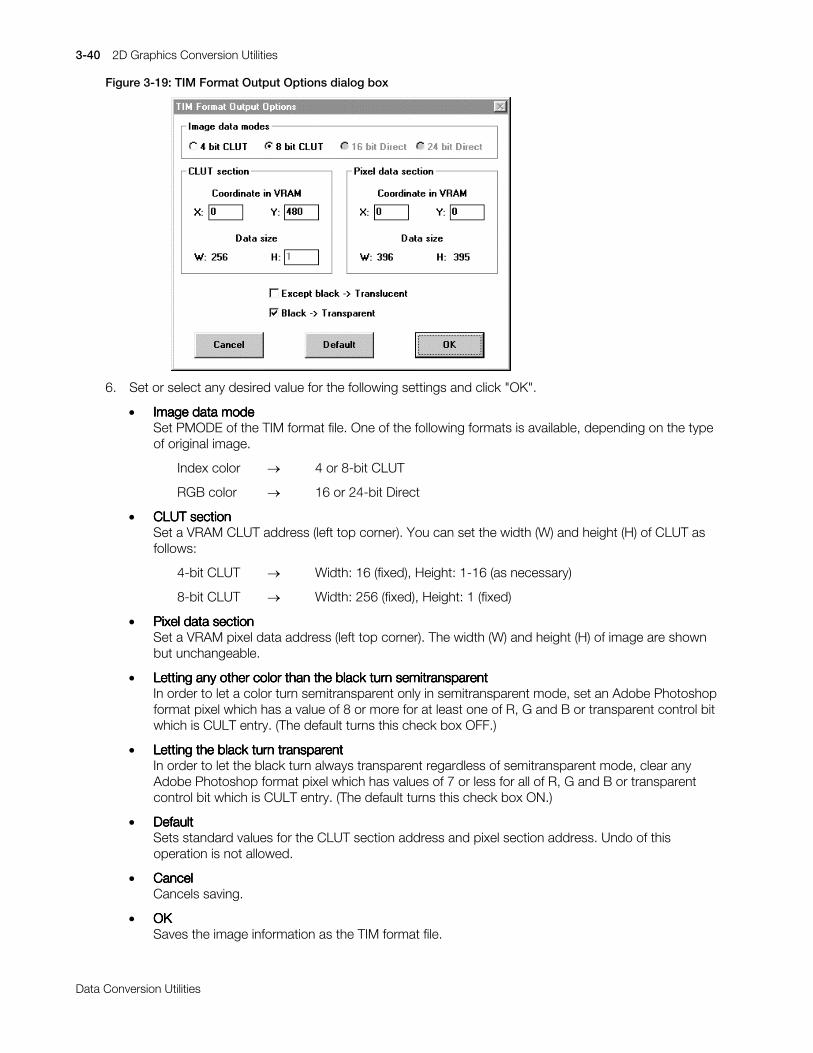
3-40 2D Graphics Conversion Utilities
Printed:11/19/98 4:16 PM By:SCEA Filename:final44Dataconv.doc Last saved by:SONY On:11/19/98 3:28 PM Comments: Master Copy, TechRef Release 4.3.
Data Conversion Utilities
Figure 3-19: TIM Format Output Options dialog box
6. Set or select any desired value for the following settings and click "OK".
x Image data modeImage data modeImage data modeImage data modeSet PMODE of the TIM format file. One of the following formats is available, depending on the typeof original image.
Index color o 4 or 8-bit CLUT
RGB color o 16 or 24-bit Direct
x CLUTCLUTCLUTCLUT section section section sectionSet a VRAM CLUT address (left top corner). You can set the width (W) and height (H) of CLUT asfollows:
4-bit CLUT o Width: 16 (fixed), Height: 1-16 (as necessary)
8-bit CLUT o Width: 256 (fixed), Height: 1 (fixed)
x Pixel data sectionPixel data sectionPixel data sectionPixel data sectionSet a VRAM pixel data address (left top corner). The width (W) and height (H) of image are shownbut unchangeable.
x Letting any other color than the black turn semitransparentLetting any other color than the black turn semitransparentLetting any other color than the black turn semitransparentLetting any other color than the black turn semitransparentIn order to let a color turn semitransparent only in semitransparent mode, set an Adobe Photoshopformat pixel which has a value of 8 or more for at least one of R, G and B or transparent control bitwhich is CULT entry. (The default turns this check box OFF.)
x Letting the black turn transparentLetting the black turn transparentLetting the black turn transparentLetting the black turn transparentIn order to let the black turn always transparent regardless of semitransparent mode, clear anyAdobe Photoshop format pixel which has values of 7 or less for all of R, G and B or transparentcontrol bit which is CULT entry. (The default turns this check box ON.)
x DefaultDefaultDefaultDefaultSets standard values for the CLUT section address and pixel section address. Undo of thisoperation is not allowed.
x CancelCancelCancelCancelCancels saving.
x OKOKOKOKSaves the image information as the TIM format file.

2D Graphics Conversion Utilities 3-41
Printed:11/19/98 4:16 PM By:SCEA Filename:final44Dataconv.doc Last saved by:SONY On:11/19/98 3:28 PM Comments: Master Copy, TechRef Release 4.3.
Data Conversion Utilities
Note
In Adobe Photoshop, components, R, G and B have the 8-bit resolution. On the other hand, each TIMformat resolution is 5-bit, except 24-bit mode. Therefore, to say strictly, equivalent conversion from AdobePhotoshop to the TIM format file is not realized. (The 24-bit mode realizes it.) This module adds '0's for 3low order bits when it opens the TIM format file and picks up 5 high order bits but ignores 3 low order bitswhen it saves the file.
For example
Adobe Photoshop TIM format file Adobe Photoshop
(R,G,B):(0x08,0x07,0xff) o (0x01,0x00,0x1f) o (0x08,0x00,0xf8)
The TIM format is provided with the transparent control bit, except 24-bit mode but Adobe Photoshop hasnothing which corresponds to it. Therefore, this module deals with the transparent control bit as follows:
When this plug-in opens the TIM fileAll transparency bits are lost. This leads both "transparent" and "(semi) nontransparent black" to the sameAdobe Photoshop value, (R, G, B)=(0, 0, 0).
When it saves a file as the TIM format fileTwo types of check box are provided to deal with the transparency control bit. These boxes allow you touse the transparency control bit to some degree. However, you cannot store "transparent" and "(semi)nontransparent black" in a TIM format file at the same time. In such cases, use (R, G, B)=(0, 0, 8) (equal to[0, 0, 1] of the TIM file) for each "black" pixel.
The Adobe Photoshop indexed color image always holds the 256-color CLUT. For the 4-bit mode TIMformat file, input and output of the CLUT of up to 256 colors are available. However, Adobe Photoshopuses only the first 16 colors to display it.
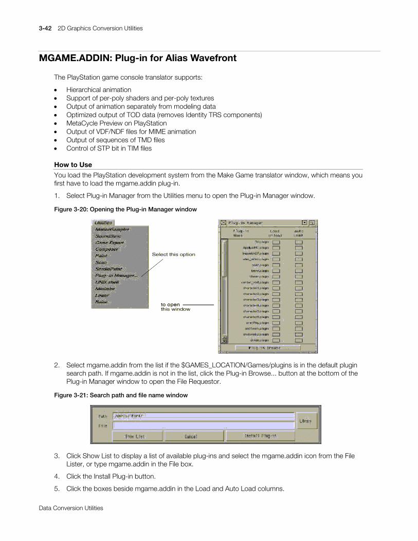
3-42 2D Graphics Conversion Utilities
Printed:11/19/98 4:16 PM By:SCEA Filename:final44Dataconv.doc Last saved by:SONY On:11/19/98 3:28 PM Comments: Master Copy, TechRef Release 4.3.
Data Conversion Utilities
MGAME.ADDIN: Plug-in for Alias Wavefront
The PlayStation game console translator supports:
x Hierarchical animationx Support of per-poly shaders and per-poly texturesx Output of animation separately from modeling datax Optimized output of TOD data (removes Identity TRS components)x MetaCycle Preview on PlayStationx Output of VDF/NDF files for MIME animationx Output of sequences of TMD filesx Control of STP bit in TIM files
How to Use
You load the PlayStation development system from the Make Game translator window, which means youfirst have to load the mgame.addin plug-in.
1. Select Plug-in Manager from the Utilities menu to open the Plug-in Manager window.
Figure 3-20: Opening the Plug-in Manager window
2. Select mgame.addin from the list if the $GAMES_LOCATION/Games/plugins is in the default pluginsearch path. If mgame.addin is not in the list, click the Plug-in Browse... button at the bottom of thePlug-in Manager window to open the File Requestor.
Figure 3-21: Search path and file name window
3. Click Show List to display a list of available plug-ins and select the mgame.addin icon from the FileLister, or type mgame.addin in the File box.
4. Click the Install Plug-in button.
5. Click the boxes beside mgame.addin in the Load and Auto Load columns.
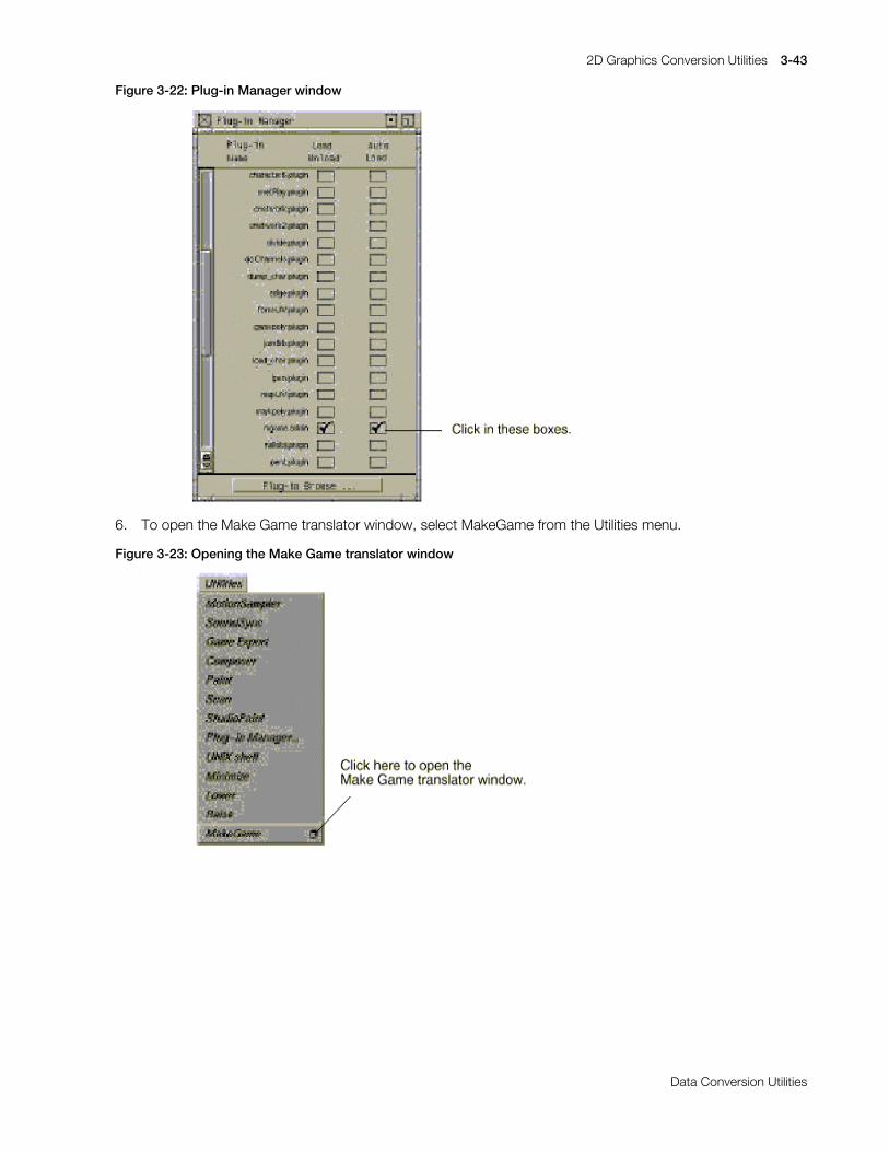
2D Graphics Conversion Utilities 3-43
Printed:11/19/98 4:16 PM By:SCEA Filename:final44Dataconv.doc Last saved by:SONY On:11/19/98 3:28 PM Comments: Master Copy, TechRef Release 4.3.
Data Conversion Utilities
Figure 3-22: Plug-in Manager window
6. To open the Make Game translator window, select MakeGame from the Utilities menu.
Figure 3-23: Opening the Make Game translator window
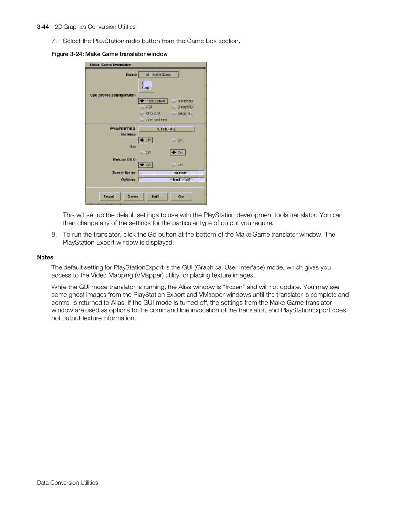
3-44 2D Graphics Conversion Utilities
Printed:11/19/98 4:16 PM By:SCEA Filename:final44Dataconv.doc Last saved by:SONY On:11/19/98 3:28 PM Comments: Master Copy, TechRef Release 4.3.
Data Conversion Utilities
7. Select the PlayStation radio button from the Game Box section.
Figure 3-24: Make Game translator window
This will set up the default settings to use with the PlayStation development tools translator. You canthen change any of the settings for the particular type of output you require.
8. To run the translator, click the Go button at the bottom of the Make Game translator window. ThePlayStation Export window is displayed.
Notes
The default setting for PlayStationExport is the GUI (Graphical User Interface) mode, which gives youaccess to the Video Mapping (VMapper) utility for placing texture images.
While the GUI mode translator is running, the Alias window is "frozen" and will not update. You may seesome ghost images from the PlayStation Export and VMapper windows until the translator is complete andcontrol is returned to Alias. If the GUI mode is turned off, the settings from the Make Game translatorwindow are used as options to the command line invocation of the translator, and PlayStationExport doesnot output texture information.
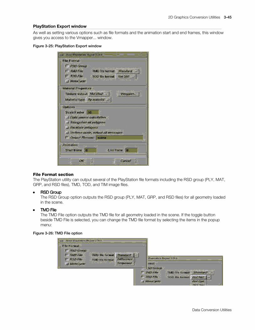
2D Graphics Conversion Utilities 3-45
Printed:11/19/98 4:16 PM By:SCEA Filename:final44Dataconv.doc Last saved by:SONY On:11/19/98 3:28 PM Comments: Master Copy, TechRef Release 4.3.
Data Conversion Utilities
PlayStation Export window
As well as setting various options such as file formats and the animation start and end frames, this windowgives you access to the Vmapper... window.
Figure 3-25: PlayStation Export window
File Format sectionThe PlayStation utility can output several of the PlayStation file formats including the RSD group (PLY, MAT,GRP, and RSD files), TMD, TOD, and TIM image files.
xxxx RSDRSDRSDRSD Group Group Group GroupThe RSD Group option outputs the RSD group (PLY, MAT, GRP, and RSD files) for all geometry loadedin the scene.
xxxx TMDTMDTMDTMD File File File FileThe TMD File option outputs the TMD file for all geometry loaded in the scene. If the toggle buttonbeside TMD File is selected, you can change the TMD file format by selecting the items in the popupmenu:
Figure 3-26: TMD File option

3-46 2D Graphics Conversion Utilities
Printed:11/19/98 4:17 PM By:SCEA Filename:final44Dataconv.doc Last saved by:SONY On:11/19/98 3:28 PM Comments: Master Copy, TechRef Release 4.3.
Data Conversion Utilities
xxxx StandardStandardStandardStandardThe Standard option outputs a TMD file for the selected frames of an animation. Frames are selectedusing the Start frame and End frame boxes at the bottom of the PlayStation Export options window.
xxxx DifferenceDifferenceDifferenceDifferenceThe Difference option outputs VDF and NDF file for the selected frames of an animation for MIMEanimation.
xxxx SequenceSequenceSequenceSequenceThe Sequence option outputs a sequence of TMD files for the selected frames of an animation.
xxxx TODTODTODTOD File File File FileThe TOD File option is only available if the scene contains animation data. Selecting this option outputsa TOD file for the animation. TOD format can be either Rotation matrices or TRS components.
xxxx Rotation matricesRotation matricesRotation matricesRotation matricesThese are more accurate, and transfer the Alias rotation matrix directly.
xxxx TRS componentsTRS componentsTRS componentsTRS componentsThis takes the Alias rotation matrix and decomposes it into TRS values that can be used in the Aliasviewer program. The axis orientation is slightly different than that of the "standard" PlayStation TODdemo program, and needs to be transposed for pre/post multiply differences. Both formats have anoption to suppress the output of data for objects that have Identity matrices or TRS components.
xxxx MetaCycle FileMetaCycle FileMetaCycle FileMetaCycle FileThe MetaCycle file option outputs a NET file, which is the animation definition file for the MetaCyclepreviewer. If the MetaCycle option is not selected, the selected range of animation will be output.
Material Properties sectionThe Material Properties section contains options for customizing your texture output attributes.
Texture output menuThese options are used to determine how the texture (TIM files) are output.
xxxx OffOffOffOffThe Off option turns texture output OFF.
xxxx TiledTiledTiledTiledSelect the Tiled option if the UV coordinates for the texture are out of the 0.0 - 1.0 range. This optiontiles the texture to account for the texture wrapping. The size of the texture is maintain.
xxxx Not tiledNot tiledNot tiledNot tiledIf you choose Not tiled, no tiling occurs on a texture if the UV coordinates are out of the range 0.0 -1.0. The UV coordinates are clipped to a 0.0 - 1.0 range.
Material type menuxxxx By materialBy materialBy materialBy material
This option outputs the texture according to the materials assigned to it in PowerAnimator.
xxxx FlatFlatFlatFlatThis option is used to convert all materials to flat shading.
xxxx GouraudGouraudGouraudGouraudThis option is used to convert all materials to Gouraud shading.

2D Graphics Conversion Utilities 3-47
Printed:11/19/98 4:17 PM By:SCEA Filename:final44Dataconv.doc Last saved by:SONY On:11/19/98 3:28 PM Comments: Master Copy, TechRef Release 4.3.
Data Conversion Utilities
Video RAM Mapper window
The Video RAM Mapper, also called the VMapper, allows you to place the textures used in the scene intothe video RAM of the PlayStation development system. The video RAM contains 32 pages, as indicated bythe two rows of vertical bars. Click the Vmapper button to display the Video RAM Mapper window.
Figure 3-27: Video RAM Mapper window
Placing texturesTo place a texture into video RAM, select a texture from the Select current texture list by clicking its name.The texture you select appears in the texture swatch window. Place the texture in a page by clicking in thetexture page window. The texture appears as a rectangle. The rectangle represents the size of the texturein video RAM. You can click-drag the texture to fit as many in each page as possible. Some rectangles mayoverlap more than one page, but you cannot place a texture over the active video area (the light blue area)of the video RAM. The texture pages with a few textures placed appear as in the following: Each texturepage is numbered from 0 to 31 and represents a texture page in PlayStation development systemhardware.
Active Video AreaThe active video area (the light blue rectangles) is the area reserved for the active video screen. You cannotplace a texture in this area. You can modify the size of your active video screen using the Screen Sizemenus in the lower left corner of the Video RAM Mapper window.
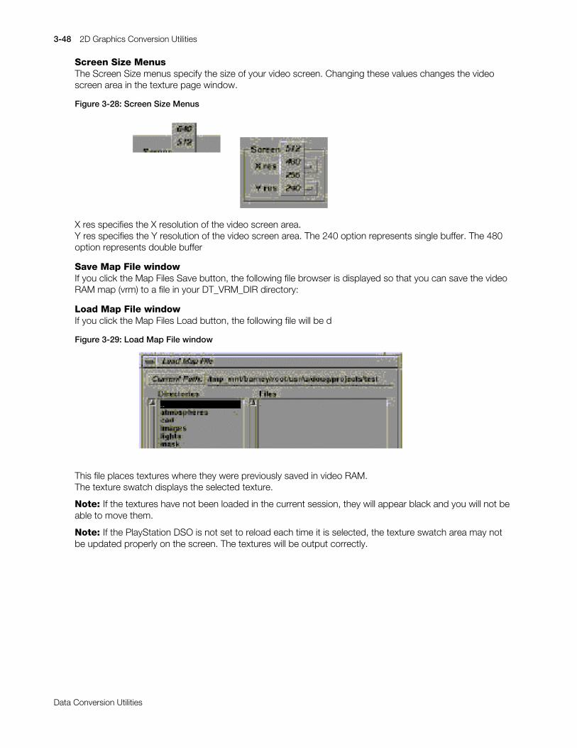
3-48 2D Graphics Conversion Utilities
Printed:11/19/98 4:17 PM By:SCEA Filename:final44Dataconv.doc Last saved by:SONY On:11/19/98 3:28 PM Comments: Master Copy, TechRef Release 4.3.
Data Conversion Utilities
Screen Size MenusThe Screen Size menus specify the size of your video screen. Changing these values changes the videoscreen area in the texture page window.
Figure 3-28: Screen Size Menus
X res specifies the X resolution of the video screen area.Y res specifies the Y resolution of the video screen area. The 240 option represents single buffer. The 480option represents double buffer
Save Map File windowIf you click the Map Files Save button, the following file browser is displayed so that you can save the videoRAM map (vrm) to a file in your DT_VRM_DIR directory:
Load Map File windowIf you click the Map Files Load button, the following file will be d
Figure 3-29: Load Map File window
This file places textures where they were previously saved in video RAM.The texture swatch displays the selected texture.
Note: If the textures have not been loaded in the current session, they will appear black and you will not beable to move them.
Note: If the PlayStation DSO is not set to reload each time it is selected, the texture swatch area may notbe updated properly on the screen. The textures will be output correctly.
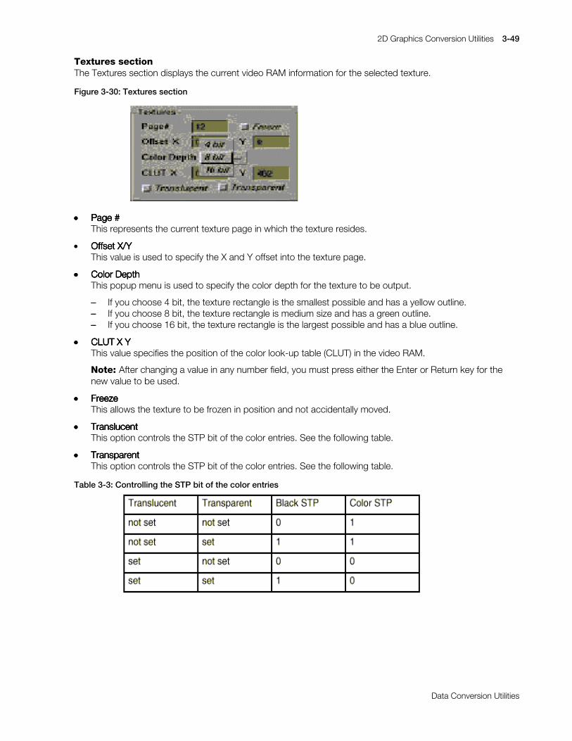
2D Graphics Conversion Utilities 3-49
Printed:11/19/98 4:17 PM By:SCEA Filename:final44Dataconv.doc Last saved by:SONY On:11/19/98 3:28 PM Comments: Master Copy, TechRef Release 4.3.
Data Conversion Utilities
Textures sectionThe Textures section displays the current video RAM information for the selected texture.
Figure 3-30: Textures section
xxxx Page #Page #Page #Page #This represents the current texture page in which the texture resides.
x Offset X/YOffset X/YOffset X/YOffset X/YThis value is used to specify the X and Y offset into the texture page.
xxxx Color DepthColor DepthColor DepthColor DepthThis popup menu is used to specify the color depth for the texture to be output.
–––– If you choose 4 bit, the texture rectangle is the smallest possible and has a yellow outline.–––– If you choose 8 bit, the texture rectangle is medium size and has a green outline.–––– If you choose 16 bit, the texture rectangle is the largest possible and has a blue outline.
xxxx CLUTCLUTCLUTCLUT X Y X Y X Y X YThis value specifies the position of the color look-up table (CLUT) in the video RAM.
Note: After changing a value in any number field, you must press either the Enter or Return key for thenew value to be used.
xxxx FreezeFreezeFreezeFreezeThis allows the texture to be frozen in position and not accidentally moved.
xxxx TranslucentTranslucentTranslucentTranslucentThis option controls the STP bit of the color entries. See the following table.
xxxx TransparentTransparentTransparentTransparentThis option controls the STP bit of the color entries. See the following table.
Table 3-3: Controlling the STP bit of the color entries
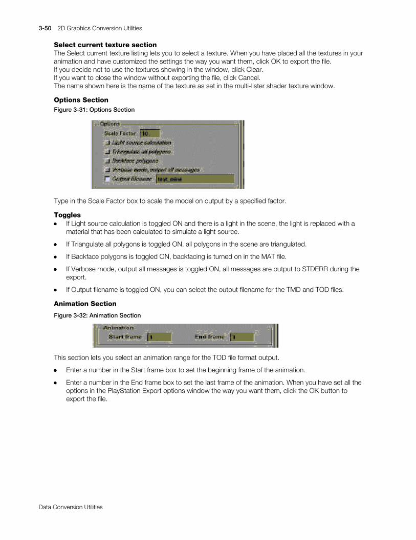
3-50 2D Graphics Conversion Utilities
Printed:11/19/98 4:17 PM By:SCEA Filename:final44Dataconv.doc Last saved by:SONY On:11/19/98 3:28 PM Comments: Master Copy, TechRef Release 4.3.
Data Conversion Utilities
Select current texture sectionThe Select current texture listing lets you to select a texture. When you have placed all the textures in youranimation and have customized the settings the way you want them, click OK to export the file.If you decide not to use the textures showing in the window, click Clear.If you want to close the window without exporting the file, click Cancel.The name shown here is the name of the texture as set in the multi-lister shader texture window.
Options SectionFigure 3-31: Options Section
Type in the Scale Factor box to scale the model on output by a specified factor.
Togglesxxxx If Light source calculation is toggled ON and there is a light in the scene, the light is replaced with a
material that has been calculated to simulate a light source.
xxxx If Triangulate all polygons is toggled ON, all polygons in the scene are triangulated.
xxxx If Backface polygons is toggled ON, backfacing is turned on in the MAT file.
xxxx If Verbose mode, output all messages is toggled ON, all messages are output to STDERR during theexport.
xxxx If Output filename is toggled ON, you can select the output filename for the TMD and TOD files.
Animation Section
Figure 3-32: Animation Section
This section lets you select an animation range for the TOD file format output.
xxxx Enter a number in the Start frame box to set the beginning frame of the animation.
xxxx Enter a number in the End frame box to set the last frame of the animation. When you have set all theoptions in the PlayStation Export options window the way you want them, click the OK button toexport the file.

2D Graphics Conversion Utilities 3-51
Printed:11/19/98 4:17 PM By:SCEA Filename:final44Dataconv.doc Last saved by:SONY On:11/19/98 3:28 PM Comments: Master Copy, TechRef Release 4.3.
Data Conversion Utilities
GetPlayStation Command Line OptionsThe GetPlayStation Dt Translator has the following options that can be used with the mgame plugin withthe option field.
GetPlayStation OptionsTable 3-4: GetPlayStation Options
Most of the command line options match the GUI user controls. See the description of the PlayStationExport window on page 5 for details of the settings.
Options with no corresponding GUI mode-x Lets you specify a shell script to run at the end of the translation process. The PlayStation also looks at
the following environment variables:
DT_PSX_BEGSCRIPT
DT_PSX_ENDSCRIPT
for commands that should be run at the beginning and the end of the translation process. The endscript process is given the name of the output scene directory and name as command line options.

3-52 2D Graphics Conversion Utilities
Printed:11/19/98 4:17 PM By:SCEA Filename:final44Dataconv.doc Last saved by:SONY On:11/19/98 3:28 PM Comments: Master Copy, TechRef Release 4.3.
Data Conversion Utilities
Additional user controls with environment settingsxxxx DT_PCNAMESDT_PCNAMESDT_PCNAMESDT_PCNAMES
This changes the names of the output files to be in a PC dos compatible format of DTF#dddd wheredddd is a 4 character digit. At the moment, there is no easy mapping of the numbers to the originalfiles.
Note: File names that fall within the DOS limitation of 8.3 are not changed.
xxxx WF_TIMWF_TIMWF_TIMWF_TIM_DIR / DT_TIM_DIR_DIR / DT_TIM_DIR_DIR / DT_TIM_DIR_DIR / DT_TIM_DIRUse this command line option to pre-define the directory to open when using the replace texturebutton.
xxxx DT_VRM_DIRDT_VRM_DIRDT_VRM_DIRDT_VRM_DIRUse this command to specify where to find the vrm files that can be saved and/or loaded.
xxxx DT_EXPORT_DIRDT_EXPORT_DIRDT_EXPORT_DIRDT_EXPORT_DIRUse this command to specify where the exported files should be placed. They will be displayed in theExport directory field of the mgame plug-in.
xxxx PSX_RSDPSX_RSDPSX_RSDPSX_RSD_SCALE_SCALE_SCALE_SCALEUse this command to use the 7.5.1 method of saving UV coordinates in the RSD material file. Thedefault is to use the texture UV size and not the position of the texture in the VRAM space.
Note: Environment variables can be entered into the text fields of mgame and will be expandedinternally.
PlayStation Demo Viewer Setup
The following information shows how to set up and use the example viewer program for the PlayStationdevelopment system.
Demo ViewerThe demo viewer for the PlayStation development tool is based on one of the demo TOD viewers from thePlayStation programmer tools CD. The program has been modified to support the MetaCycle feature ofAlias and the PlayStation translator. Also, due to differences in the pre/post multiply differences in matrixapplications the component (TRS) packet code for the viewer has been tuned to the output of thetranslator. The rotational matrices packet is the same for the original demo program. It views TMD files andTMD/TOD files, with or without texture TIM files. It also supports the MetaCycle NET files that are createdwith the PlayStation translator GetPlayStation.
The files that are found in this area are used for running the PlayStation utilities on an Intel platform. (Thesewere used under Windows 95).

2D Graphics Conversion Utilities 3-53
Printed:11/19/98 4:17 PM By:SCEA Filename:final44Dataconv.doc Last saved by:SONY On:11/19/98 3:28 PM Comments: Master Copy, TechRef Release 4.3.
Data Conversion Utilities
The batch file looks for the files test.tmd, test.tod, test.net, and *.tim files in the user supplied directory.
Run as:
netv h:\GET\download
where
h:\GET\download
will have the files test.tmd...
The batch file is setup to look for known file names (test.*)in the directory specified as a parameter.
Unix ScriptsThe unix scripts psx_begscript and psx_endscript have been supplied to show how one might use them toimplement a one button download from Alias to the PlayStation development system.
On the SGI workstation, you have to set the environment variables PSX_BEGSCRIPT andPSX_ENDSCRIPT to the full path names of shell scripts to be run before and after the translation processtakes place.
This can be used as a simple auto-load script for continuous hands-free one button downloading fromwithin Alias. You would normally have to have the PC on the network with the SGI workstations. There aremany ways to do this, one of which is using Samba (a freeware program from Australia that runs on theSGI and makes it look like a Microsoft network machine).
Installation Notes
Installing PlayStation TranslatorThis section describes how to install a translator as supplied directly from Sony Computer Entertainment'sBBS or developer's CDROM.
Distribution of PlayStation TranslatorThe PlayStation translator is distributed by Sony Computer Entertainment on their BBS and developers CD.The file that can be downloaded or copied from the CD is an un-encrypted compressed tar file containingthe PlayStation translator, PlayStation TIM image module, source code and make file to build the translatorlocally.
To install the PlayStation translator, use the InstallGame script file that is found in the$ALIAS_LOCATION/ODS/Games/bin directory. This script is installed as part of the standard Aliasinstallation process.
This script file takes the compressed tar file, uncompresses it, and untars it to the location you specify.There are command line arguments to override the default installation locations.
Installing the new downloaded version of PlayStation TranslatorThe shell script InstallGame is run to extract the components of the translator and place them into theproper directory tree for use within the Alias game tools environment. The command line options that areavailable for InstallGame can be found by running the script with the parameter -h as shown below:
3-54 2D Graphics Conversion Utilities
Printed:11/19/98 4:17 PM By:SCEA Filename:final44Dataconv.doc Last saved by:SONY On:11/19/98 3:28 PM Comments: Master Copy, TechRef Release 4.3.
Data Conversion Utilities
$ALIAS_LOCATION/ODS/Games/bin/InstallGame -h
outputs the command line options that can be used.
Usage: InstallGame <-hdeaftsk>where: -h prints this usage info-e assume files are not encrypted-d decrypt the library file only-a dir alias directory location-f dir install from this directory-t dir install to this directory-s System install this System
Default with no options on command line is to use the $ALIAS_LOCATION/ODS/ Games/support directoryas the source directory and to install back into the ODS/ Games directory. Use absolute paths for the fromand to directories
Note: When running as root, ensure that $ALIAS_LOCATION is set correctly
What you need to know:1. Where the original compressed file is located
2. Where the expanded file is to be placed. ($ALIAS_LOCATION/ODS/Games)
3. Where Alias 8.0 is installed
Defaults:1. Original compressed file has no default location. It is wherever you placed it.
2. For an expanded file, the default is in the Games area under Alias 8.0 installation$ALIAS_LOCATION/ODS/Games
3. Alias 8.0 defaults to /usr/aw/alias if ALIAS_LOCATION is not set.
Access:If the installation is to write out to the Alias installation area, you will need to have access to the rootpassword in order to become the super-user. For local installations, root access is not necessary.For example, to change to root and install the PlayStation translator from the compressed tar file SO in yourhome directory to the expanded tree under the Games tree of Alias 8.0, type:
su -l root
setenv ALIAS_LOCATION /usr/aw/alias
ALIAS_LOCATION/ODS/Games/bin/InstallGame -e -f $HOME -s SO
How to run the translatorThe translator is run from within Alias using the Makegame plugin. See the Games Data Transfer book formore information on makegame usage.
How to rebuild the translatorThe following method is recommended to rebuild the PlayStation translator:
1. Create a games tree under your $HOME directory somewhere.
Fill it with the following directories: lib, include, Dtplugins, PlayStationcd $HOMEmkdir Gamescd Gamesmkdir libmkdir includemkdir Dtpluginsmkdir PlayStation
2D Graphics Conversion Utilities 3-55
Printed:11/19/98 4:17 PM By:SCEA Filename:final44Dataconv.doc Last saved by:SONY On:11/19/98 3:28 PM Comments: Master Copy, TechRef Release 4.3.
Data Conversion Utilities
2. Copy the source files from the following directory
$ALIAS_LOCATION/ODS/Games/source/PlayStation/src
to this new Games/PlayStation directory
cp $ALIAS_LOCATION/ODS/Games/source/PlayStation/src/* PlayStation
3. Check the Makefile for the proper setting of GAMES_LOCATION.
For example:
$SITEROOT defines the "Site" directory of the development tree. It is a relative path from this currentdirectory. All other $variables in this Makefile should be relative to SITEROOT.
$SITEROOT = $(GAMES_LOCATION) INCDIR = $(SITEROOT)/include
GAMES_LOCATION set to $ALIAS_LOCATION/ODS/Games will then use standard Games includeand library files. If the library DtOMio is to be changed as well, it is easiest to point GAMES_LOCATIONto the root of the "local Games" tree. (In the example above, $HOME/Games.) Make sure that the filesin the include directory are copied over to the modified Games tree.
4. Type make
This should rebuild the translator DSO GetPlayStation
5. In order for makegame to see the new version of the DSO, you will need to set the followingenvironment variable.
setenv DT_PLUGIN_LOCATION $HOME/Games/PlayStation
Using standard libraries, you only need to set DT_PLUGIN_LOCATION to point to the location wherethe DSO is found.
Note: The PlayStation translator is normally located in the same directory as GetPlayStation
Using modified libraries, set GAMES_LOCATION to point to the root of the modified Games tree.
Note: The libDtxxx.so files from the $ALIAS_LOCATION/ODS/Games/lib directory should either becopied to this new tree or have symlinks created.
6. Run Alias or DtExport to test the new version of the translator.
Release Notes
Version 2.0b3 Improvementsxxxx control of STP bit in TIM files has been addedxxxx control of material UV coordinates has been extended
Version 1.0 Improvementsxxxx 256 and 512 PAL screen sizes have been addedxxxx The default TIM depth has been changed to 4 bit
Limitationsxxxx Solid textures are not supported directly in the Dt translatorsxxxx TOD format for TRS data is in Alias orientation and not standard TOD.xxxx The example TOD viewer supplied with the Alias translator shows the matrix order that the angles are
supplied in.
Modeling LimitationTOD format has a maximum scaling factor of 8.0 in the 16 bit fixed point format that is specified. Scaling is(1,3,12), with 1.0 = 4096.
Model in Alias so as the scaling components of the transformations are less than 8.0.

3-56 2D Graphics Conversion Utilities
Printed:11/19/98 4:17 PM By:SCEA Filename:final44Dataconv.doc Last saved by:SONY On:11/19/98 3:28 PM Comments: Master Copy, TechRef Release 4.3.
Data Conversion Utilities
User Interface - WorkFlow notes
x When entering numeric data into the fields on the VMapper window, you must press Enter to actuallyset the data
x Similar to the above, when you change focus, the values in the numeric text fields will only be set whenyou press the Enter key.
x Screen area definition does not relate to programming (for example double buffering using the 2xscreen area
x Running the VMapper window multiple times causes the texture swatch area to become corrupted.Textures still output correctly. (Run the translator in "Reload DSO" mode if this is a problem, but notethat it will start up slower.)
x It is possible to position TIM over a page boundary illegally when the texture is placed between twoother textures already placed.
x It is possible to overlap a larger TIM over a smaller TIM.
x Default numbering of color look-up tables (CLUTs) may position them over the 511 limit.

2D Graphics Conversion Utilities 3-57
Printed:11/19/98 4:17 PM By:SCEA Filename:final44Dataconv.doc Last saved by:SONY On:11/19/98 3:28 PM Comments: Master Copy, TechRef Release 4.3.
Data Conversion Utilities
TOD_I.KXP: Plug-in for 3D Studio
Version 4.0f
Documentation date: 12/26/95
Document
3dstod_e.txt (English)
3dstod_j.txt (Japanese)
Installation and behavior check
Installation method is written in the document. In order to check the "Previewer" feature of the tool, loadsample data containing animation data into 3D Studio, and invoke the plug-in. Then click the Previewbutton. If the tool is running correctly, you will see the animation running on DTL-H2000.
In order to check the "Save RSD" and "Save TOD" features, click "Save RSD" button, and "Save TOD"button. Check the data by giving those data to the TOD previewer on DTL-H2000.
Sony Computer Entertainment makes no expressed or implied warranty of any kind with regard to theseprograms or to the supplemental documentation in this manual. In no even shall Sony ComputerEntertainment be liable for incidental or consequential damages in connection with or arising out of thisprogram or documentation. This disclaimer includes, but is not limited to, any loss of service, loss ofbusiness, or anticipatory profits, or consequential damages resulting from the use or operation of theenclosed software.
3D Studio is a trade mark of Autodesk Inc.
PlayStation is a trade mark of Sony Computer Entertainment Inc.
Function
This program is a plug-in program for the Autodesk 3D Studio (3DS).
With this plug-in, you can save 3DS object or animation data in PlayStation format (RST ,TOD) while using3DS. You can also preview animation while using 3DS by sending animation data to PlayStation board(DTL-H2000).
Release History
Version 4.0f
Bug FixesBug FixesBug FixesBug Fixes
1. Texture map UV value had been incorrect.
Version 4.0e
Bug FixesBug FixesBug FixesBug Fixes
1. Dummy object's parent was not correctly saved into TOD file.
2. Texture UV was incorrect in some cases.
For instance, if a texture pixel size is w * h,
the correct UV range is (0,0) to (h-1, w-1),
however, the UV range was shown as (0,0) to (h,w).
3. TOD preview is now compiled with latest (version 3.*) library.
You have to re-install the previewer. Please read installation section.
3-58 2D Graphics Conversion Utilities
Printed:11/19/98 4:17 PM By:SCEA Filename:final44Dataconv.doc Last saved by:SONY On:11/19/98 3:28 PM Comments: Master Copy, TechRef Release 4.3.
Data Conversion Utilities
Version 4.0d
New FeaturesNew FeaturesNew FeaturesNew Features
1. You can save hierarchy data into TOD file.
2. You can select RST (Rotation, Scale, Translation) packet type.
3. Load object from TOD plug-in dialog.
4. Save (and load) plug TOD plug-in parameters into TOD.INI file.
Bug FixesBug FixesBug FixesBug Fixes
1. There was a bug in scaling objects.
Version 3.11. Object scale is converted to TOD data.
2. Some sample data (for instance, IK_*.3DS) could not be handled in version 2.1. This version canhandle them.
3. You can preview or save animation without re-invoking the plug-in.
4. You can specify start and end frame of an animation to preview or save.
5. Objects with more than 10 textures could not be processed in version 2.1. This version can handlethem.
6. In "Quick Preview" only TOD file is generated. TMD files are generated only once when you invoke"Preview".
7. You can save RSD file and TOD file independently.
Version 2.11. You can save camera animation data into TOD, and preview it.
2. You can save mesh objects in RSD files.
3. You can configure the plug-in environment.
RequirementsThis plug-in runs only on 3DS R4.
In order to use the previewer function, you also need DTL-H2000.
FilesThis plug-in kit contains the following files:
3dstod_e.txt Document in English3dstod_j.txt Document in Japanese
tod_i.kxp Plug-in module.tod.ini Configuration file sample.
psboard.ini DTL-H2000 port address configuration file.psbload.exe Communication program between DTL-H2000 and PCpsreset.exe Communication program between DTL-H2000 and PCpsrun.exe Communication program between DTL-H2000 and PC
patchj.exe DTL-H2000 patch program (Japanese version)patchw.exe DTL-H2000 patch program (non-Japanese version)
todvj.bat TOD previewer batch file (Japanese version)todvw.bat TOD previewer batch file (non-Japanese version)

2D Graphics Conversion Utilities 3-59
Printed:11/19/98 4:17 PM By:SCEA Filename:final44Dataconv.doc Last saved by:SONY On:11/19/98 3:28 PM Comments: Master Copy, TechRef Release 4.3.
Data Conversion Utilities
todview5.exe TOD previewertodview5.c TOD previewer source code
If you use do not use the preview feature, you need only three files,
"tod_i.kxp", "tod.txt", and "tod.ini".
Installation
1. Copy plug-in module "tod_i.kxp" to the "process" directory in the 3DS home directory.
If you have installed your 3DS into "c:\3ds4", then you have to copy
"tod_i.kxp" to "c:\3ds4\process" directory.
2. Copy configuration file "tod.ini" into 3DS home directory.
If you do not use the TOD previewer, installation is complete.
If you do use TOD previewer, follow the installation steps below.
3. Copy "psboard.ini" to root directory "c:\".
This file specifies the port address of DTL-H2000.
If your DTL-H2000 card's port address is 0x1340, then the file must contain a line as follows.
addr=0x1340
4. Copy all the following files to "c:\psxgraph\bin".
todvj.battodvw.batpsbload.exepsreset.exepsrun.exepatchj.exepatchw.exetodview5.exe
If you are using the Japanese version of DTL-H2000, you have to rename "todvj.bat" to "todv.bat". Ifyou are using the non-Japanese version of DTL-H2000, you have to rename "todvw.bat" to "todv.bat".You can change the location of these programs. Please read the customization section.
5. Create working directory "c:\tmp" for the previewer. You can change the working directory. Pleaseread the customization section. Installation is complete.
Notes
The TOD previewer does not work properly if "DEXBIOS" is running on your PC. If you have one, you candelete them from PC memory as follows:
C:\> dexbios
If you see a message "Removing DEXBIOS" on the screen, then "DEXBIOS" is removed from memory.
Be aware that if you invoke the command when "DEXBIOS" is not running, this causes DEXBIOS to start.
You will then need to invoke the dexbios command again until you see the "Removing DEXBIOS" messageon your screen.
How to start
1. In the KeyFramer of 3DS, press "F12" key.
2. Select "TOD" from KXP plug-in list.
3-60 2D Graphics Conversion Utilities
Printed:11/19/98 4:17 PM By:SCEA Filename:final44Dataconv.doc Last saved by:SONY On:11/19/98 3:28 PM Comments: Master Copy, TechRef Release 4.3.
Data Conversion Utilities
Previewer key bind
The previewer's key bind is as follows:
L1, L2 Change BG color
SELECT Pause
START Reset Pause
You can proceed frame by frame, using SELECT key while you are in the Pause mode.
Functions
ScaleScales size of object size and translation of object/camera.
For instance, if you set scale value to 10.0, then the object size and translation of object and camera isexpanded 10 times.
You can specify the scale value to control the object size. Also, you use this value to get rid of the near-clip,far-clip and z-sort problems, which will occur on PS.
Frames from___ to ___Specify regions of animation frames you want to preview or save. You can use this function to extract someportion of animation, or to divide one animation to some pieces.
TOD typeSpecify TOD packet type.
Matrix MATRIX (Rotation Matrix + Translation)
RST RST (Rotation vector, Scale, Translation)
Animation will look same whether you chose Matrix or RST. RST data is converted to Matrix on PlayStation,therefore RST type TOD animation will consume much CPU power.
HierarchyOn Hierarchy relation of objects is saved.
Off Hierarchy relation of objects is not saved.
The animation will look same whether you chose On or Off. When you chose On, each object's animationdata will be relative to its parent object. Whereas if you chose Off, the animation data will be relative to theWORLD.
You do not have to save hierarchy information as far as you play the TOD data. But, if you have to animatea body of a robot with you program, for example, hands and legs of the robot will be disconnectedbecause they are not linked to the body. In such a case you should save hierarchy information in the TODfile.
In order to support hierarchy structure, dummy objects in 3DS will be saved in TOD file. Dummy object willbe represented as an object which has coordination data only (TMD is null).
FramesThin down the frame data.
All saves all frames
1/2 saved every 2 frames
1/3 saved every 3 frames
1/4 saved every 4 frames
1/5 saved every 5 frames

2D Graphics Conversion Utilities 3-61
Printed:11/19/98 4:17 PM By:SCEA Filename:final44Dataconv.doc Last saved by:SONY On:11/19/98 3:28 PM Comments: Master Copy, TechRef Release 4.3.
Data Conversion Utilities
If you specify "1/4", then only frames "1,5,9,13,..." will be saved. This will make the TOD data size 1/4. Youcan interpolate between frames to reproduce the original animation sequence on PlayStation. You can usethis method to reduce the size of TOD data.
The TOD previewer included in this tool, does not do interpolation. If the previewer finds some framesmissing, then it will draw the previous frames again. For instance, if you had specified "1/3", then theframes will be like this.
TOD frames: 1, 4, 7, 10, ...Drawn frames: 1,1,1,4,4,4,7,7,7,10, ...
Load objLoads new 3DS file without exiting from TOD plug-in.
PreviewInvokes animation previewer on DTL-H2000.
When you click this button, object data is saved as temporal RSD files. Then RSDLINK command convertsthe RSD files into one TMD file. Then, animation data is save as one TOD file. The TMD file and TOD file aretransferred to DTL-H2000, where TOD previewer is invoked.
You can speed up the invocation of the previewer by placing the working directory (specified as TMP_DIRin TOD.INI file) in the RAMDRIVE of you PC.
Quick PreviewInvokes animation previewer on DTL-H2000.
Only TOD file (animation data file) is generated. Instead of generating new TMD file (object data), previouslygenerated TMD file found in (c:\tmp\tmp.tmd) is used for previewing.
Quick Preview is useful when you have finished editing objects and you are frequently changing animationdata only. In such cases, you invoke "Previewer" only once, and you can invoke repeatedly "QuickPreviewer" after that. This speeds up the previewing process, because "Quick Previewer" skips generatingRSD files and TMD file.
In order to make object scale and animation scale reasonable, you have to set the scale value of "Preview"phase and the "Quick Preview" phase same. If you need to change the scale value, you have to invoke"Previewer" in order to save TMD file (object data) in the new scale.
Save RSDObject data is saved as RSD file.
Each object is saved as different RSD file.
System will ask "Generate File name automatically?".
If you choose "Yes", system asks you a base name which will be used to generate new file names. Systemadds hexadecimal 3 digit to the end of the base name. Therefore only first five letters are used as basename.
For instance, if you give "c:\psxgraph\data\rsd\mydata.rsd" as the base name, following RSD files will begenerated automatically.
c:\psxgraph\data\rsd\mydat000.rsd
mydat001.rsdmydat002.rsd...mydat00e.rsdmydat00f.rsdmydat010.rsd...mydatfff.rsd
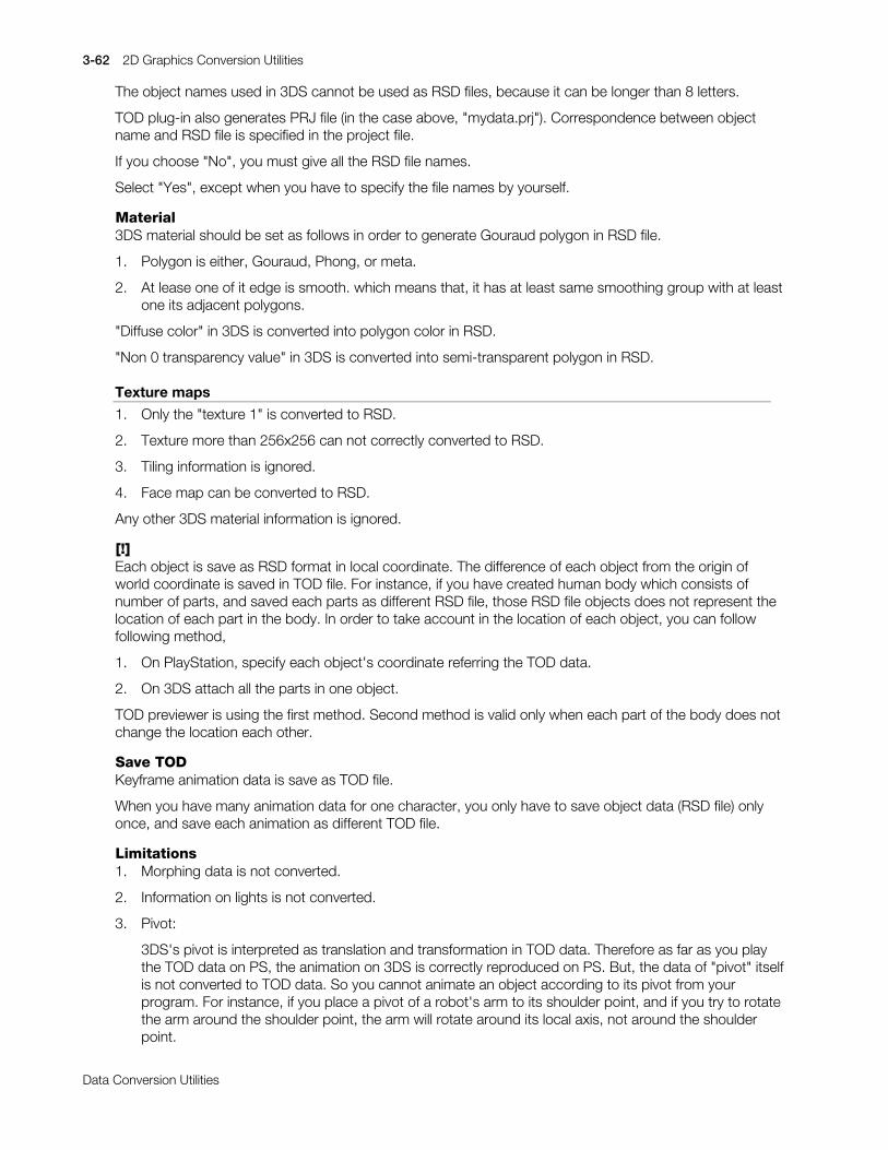
3-62 2D Graphics Conversion Utilities
Printed:11/19/98 4:17 PM By:SCEA Filename:final44Dataconv.doc Last saved by:SONY On:11/19/98 3:28 PM Comments: Master Copy, TechRef Release 4.3.
Data Conversion Utilities
The object names used in 3DS cannot be used as RSD files, because it can be longer than 8 letters.
TOD plug-in also generates PRJ file (in the case above, "mydata.prj"). Correspondence between objectname and RSD file is specified in the project file.
If you choose "No", you must give all the RSD file names.
Select "Yes", except when you have to specify the file names by yourself.
Material3DS material should be set as follows in order to generate Gouraud polygon in RSD file.
1. Polygon is either, Gouraud, Phong, or meta.
2. At lease one of it edge is smooth. which means that, it has at least same smoothing group with at leastone its adjacent polygons.
"Diffuse color" in 3DS is converted into polygon color in RSD.
"Non 0 transparency value" in 3DS is converted into semi-transparent polygon in RSD.
Texture maps
1. Only the "texture 1" is converted to RSD.
2. Texture more than 256x256 can not correctly converted to RSD.
3. Tiling information is ignored.
4. Face map can be converted to RSD.
Any other 3DS material information is ignored.
[!]Each object is save as RSD format in local coordinate. The difference of each object from the origin ofworld coordinate is saved in TOD file. For instance, if you have created human body which consists ofnumber of parts, and saved each parts as different RSD file, those RSD file objects does not represent thelocation of each part in the body. In order to take account in the location of each object, you can followfollowing method,
1. On PlayStation, specify each object's coordinate referring the TOD data.
2. On 3DS attach all the parts in one object.
TOD previewer is using the first method. Second method is valid only when each part of the body does notchange the location each other.
Save TODKeyframe animation data is save as TOD file.
When you have many animation data for one character, you only have to save object data (RSD file) onlyonce, and save each animation as different TOD file.
Limitations1. Morphing data is not converted.
2. Information on lights is not converted.
3. Pivot:
3DS's pivot is interpreted as translation and transformation in TOD data. Therefore as far as you playthe TOD data on PS, the animation on 3DS is correctly reproduced on PS. But, the data of "pivot" itselfis not converted to TOD data. So you cannot animate an object according to its pivot from yourprogram. For instance, if you place a pivot of a robot's arm to its shoulder point, and if you try to rotatethe arm around the shoulder point, the arm will rotate around its local axis, not around the shoulderpoint.
2D Graphics Conversion Utilities 3-63
Printed:11/19/98 4:17 PM By:SCEA Filename:final44Dataconv.doc Last saved by:SONY On:11/19/98 3:28 PM Comments: Master Copy, TechRef Release 4.3.
Data Conversion Utilities
You can use "dummy object" instead of pivot, to change the rotation axis.
4. Link information:
In 3DS, you can specify whether to propagate the rotation and scaling information from the parentobject to the child object or not. On the other hand, PlayStation's library (libgs) always propagate thoseinformation from the parent to the child. Therefore, if you specify not to propagate any of thoseinformation on 3DS, the resultant TOD will not reproduce the same effect. To avoid those problems,you should not stop propagating the information from the parent to the child.
5. Scaling:
If the scale value exceed 8.0 on 3DS, it will not apply properly on PlayStation. It is because, PlayStationuses fix-point for the scale value. "8.0" is the maximum scaling value expressed in fix-point (4096 * 8).Notice that, in hierarchly linked object, scale values are multiplied from all thorough it ancestors. So thescale value could exceed 8.0 even if its local scale is less than 8.0.
Generated FilesTOD plug-in generates following files.
1. PreviewIn temporary directory (c:\tmp),
RSD filestmp.3dstmp.prjtmp.tmdtmp.tod
2. Quick PreviewIn temporary directory (c:\tmp),
tmp.tod
3. Save RSDIn temporary directory (c:\tmp),
tmp.3ds
In user specified directory.
RSD filesPRJ file
4. Save TODIn user specified directory.
TOD file
CustomizationThe TOD plug-in invokes TOD previewer as follows.
c:\psxgraph\bin\todv c:\tmp\__000__.tmd c:\tmp\__000__.tod
The argument specifies an TOD file to preview. This file is created by the TOD plug-in. You can substitutethe previewer batch command "todv.bat" with your own previewer.
InformationIf you have any question on this program, please contact us (SCE).
It is useless to call Autodesk, because they do not take any charge of this program.

3-64 2D Graphics Conversion Utilities
Printed:11/19/98 4:17 PM By:SCEA Filename:final44Dataconv.doc Last saved by:SONY On:11/19/98 3:28 PM Comments: Master Copy, TechRef Release 4.3.
Data Conversion Utilities
Plug-ins for LightWave 3D 4.0
Version Beta.2 (Intel, Alpha, SGI)
Documentation date: 5/1/96
Installation
1. Copy the appropriate plug-in file for your system to your plugins/modeler and plugins/layout directory.
To plugins/modeler:
RSDLOAD.P (RSD Geometry file loader)
RSDSAVE.p (RSD Geometry file saver)
To plugins/layout:
TIMIMAGE.P (TIM Image file loader and saver)
2. Add RSDLOAD.P and RSDSAVE.P to your Modeler
Start LightWave Modeler 4.0 and choose "Add Plugin" from the "Objects/Custom" pop-up.
Select the plug-ins from the file requestor. In the "Custom" menu, you will find "RSDLOAD.P" and"RSDSAVE.P" added to the list. When you quit Modeler, the plug-ins will be saved in the list for futureuse.
3. Add TIMIMAGE.P to your LightWave
Start LightWave 4.0 and choose "Add Plug-ins" from the "Options" pop-up.
Select the plug-ins from the file requestor. In the "RGB Image Format" popup from the "Record"menu, you will find "TIMIMAGE.P" added to the list. When you quit LightWave, the plug-ins will besaved in the list for future use.
Instructions
RSD file is the geometry file for the PlayStation. It has 4 separate files such as (.rsd), (.ply), (.grp) and (.ply)file.
RSDSAVE.P exports above files from Modeler. To export (.rsd) files, select "RSD_EXPORT(Ver.1.0)" fromthe "Custom" popup in the "Object" menu and type a file name to export your geometry without suffix fromthe file requestor.
Tips: PlayStation can read only 3 and 4 vertices polygons. If the geometry has >4 vertices polygons, thenthe RSDSAVE Plugin show you the error message dialog. You can triple >4 vertices polygons with T-keyafter finding >4 vertices polygons with the "Stats" button from the "Display" menu (same as w-key).
RSDLOAD.P imports the (.rsd) files to Modeler. To import (.rsd) files, push the "Load" button from the"Objects" menu. And choose the (.rsd) file to import from the file requestor. the RSDLOAD automaticallyreads the (.rsd) file included (.ply) and (.grp) files to your Modeler.
Note: PlayStation and LightWave have different texture mapping method. You lost all of texture vertices inthe (.rsd) file in the Modeler when you load your (.rsd) file with texture uv vertices in the (.mat) file.
TIMIMAGE.P load and save Sony TIM image format files to the LightWave. You can use any TIM image fileas the texture mapping images in your animations and you can save your rendered image as the TIM imagefiles.

2D Graphics Conversion Utilities 3-65
Printed:11/19/98 4:17 PM By:SCEA Filename:final44Dataconv.doc Last saved by:SONY On:11/19/98 3:28 PM Comments: Master Copy, TechRef Release 4.3.
Data Conversion Utilities
TIMIMAGE.P supports following TIM image format.
To load: 4bit CLUT (Color Look Up Table)8bit CLUT16bit Direct color24bit Direct color
To save: 24bit Direct color
To load the TIM image files to your LightWave, select "Load Image" button from the "Images" menu, andchoose the (.tim) file to load from the file requestor.
To save the TIM image files from your LightWave, select "PlayStation(.tim)" popup from the "RGB imageformat" in the "Record" menu, and specify (.tim) file name from "Save RGB images" and render your scene.
Caution: Do not copy these plug-ins to anybody. They are still beta version.

3-66 2D Graphics Conversion Utilities
Printed:11/19/98 4:17 PM By:SCEA Filename:final44Dataconv.doc Last saved by:SONY On:11/19/98 3:28 PM Comments: Master Copy, TechRef Release 4.3.
Data Conversion Utilities

Printed:11/19/98 4:17 PM By:SCEA Filename:final44Dataconv.doc Last saved by:SONY On:11/19/98 3:28 PM Comments: Master Copy, TechRef Release 4.3.
Data Conversion Utilities
Chapter 4:Sound Conversion Utilities

4-2 Sound Conversion Utilities
Printed:11/19/98 4:17 PM By:SCEA Filename:final44Dataconv.doc Last saved by:SONY On:11/19/98 3:28 PM Comments: Master Copy, TechRef Release 4.3.
Data Conversion Utilities
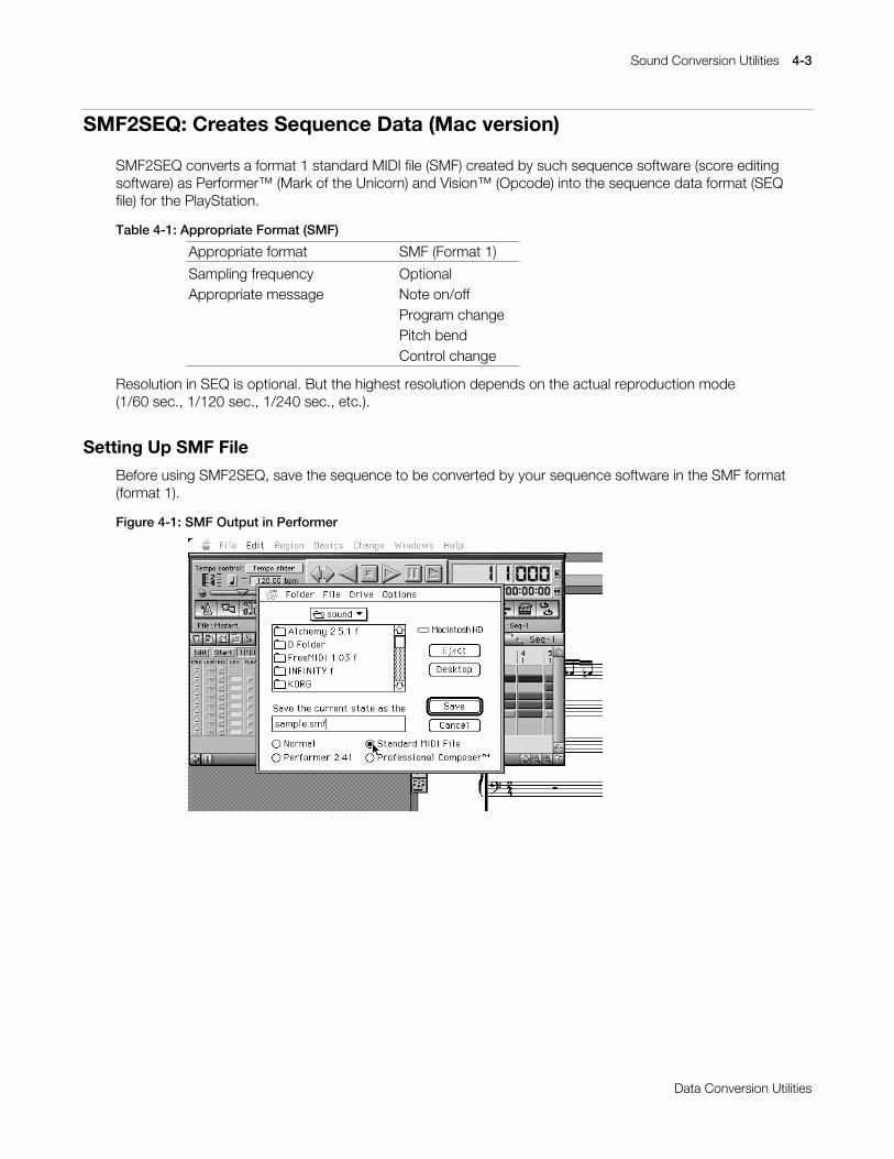
Sound Conversion Utilities 4-3
Printed:11/19/98 4:17 PM By:SCEA Filename:final44Dataconv.doc Last saved by:SONY On:11/19/98 3:28 PM Comments: Master Copy, TechRef Release 4.3.
Data Conversion Utilities
SMF2SEQ: Creates Sequence Data (Mac version)
SMF2SEQ converts a format 1 standard MIDI file (SMF) created by such sequence software (score editingsoftware) as Performer™ (Mark of the Unicorn) and Vision™ (Opcode) into the sequence data format (SEQfile) for the PlayStation.
Table 4-1: Appropriate Format (SMF)
Appropriate format SMF (Format 1)
Sampling frequency OptionalAppropriate message Note on/off
Program changePitch bendControl change
Resolution in SEQ is optional. But the highest resolution depends on the actual reproduction mode(1/60 sec., 1/120 sec., 1/240 sec., etc.).
Setting Up SMF File
Before using SMF2SEQ, save the sequence to be converted by your sequence software in the SMF format(format 1).
Figure 4-1: SMF Output in Performer
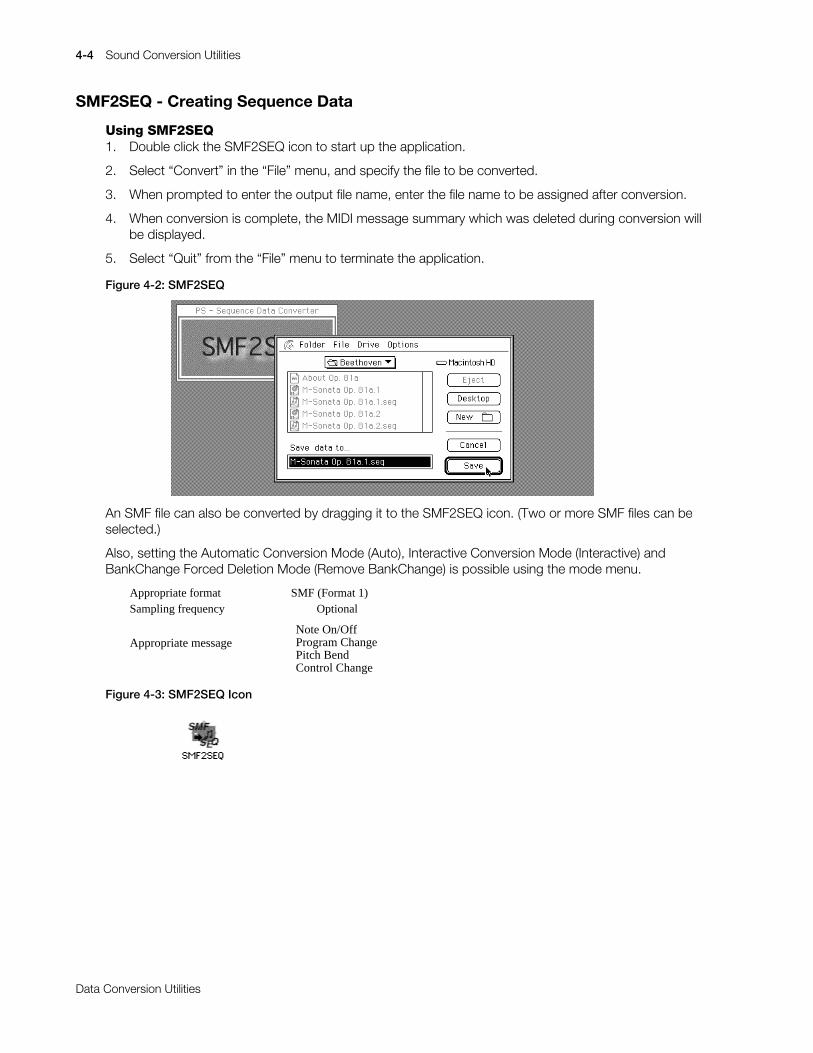
4-4 Sound Conversion Utilities
Printed:11/19/98 4:17 PM By:SCEA Filename:final44Dataconv.doc Last saved by:SONY On:11/19/98 3:28 PM Comments: Master Copy, TechRef Release 4.3.
Data Conversion Utilities
SMF2SEQ - Creating Sequence Data
Using SMF2SEQ1. Double click the SMF2SEQ icon to start up the application.
2. Select “Convert” in the “File” menu, and specify the file to be converted.
3. When prompted to enter the output file name, enter the file name to be assigned after conversion.
4. When conversion is complete, the MIDI message summary which was deleted during conversion willbe displayed.
5. Select “Quit” from the “File” menu to terminate the application.
Figure 4-2: SMF2SEQ
An SMF file can also be converted by dragging it to the SMF2SEQ icon. (Two or more SMF files can beselected.)
Also, setting the Automatic Conversion Mode (Auto), Interactive Conversion Mode (Interactive) andBankChange Forced Deletion Mode (Remove BankChange) is possible using the mode menu.
Appropriate format SMF (Format 1)Sampling frequency Optional
Appropriate messageNote On/OffProgram ChangePitch BendControl Change
Figure 4-3: SMF2SEQ Icon

Sound Conversion Utilities 4-5
Printed:11/19/98 4:17 PM By:SCEA Filename:final44Dataconv.doc Last saved by:SONY On:11/19/98 3:28 PM Comments: Master Copy, TechRef Release 4.3.
Data Conversion Utilities
SMF2SEQ: Creates Sequence Data (PC version)
Version 2.4
Documentation date: 10/26/98
Description
smf2seq converts format 1 standard MIDI file (SMF) data to a PlayStation sequence data file.
How to use
smf2seq[options]SMF-files...
Inputting a format 1 file as an argument creates an SEQ file (*.SEQ), which is a PlayStation sequence datafile. Multiple files can be given to perform batch conversions. The file extension [.smf] can be used.
Options
-Q Converts using quiet mode. No warning messages are displayed.
-V Converts using verbose mode. The control change and meta events used by SMF are listed.
-B Forcibly deletes the bank change used by SMF.
Constraints
The current version has the following constraints:
xý It is not compatible with SMF format 0.
xý It cannot handle files larger than 64 Kbytes.
xý The compatible control changes are as follows:
Bank Select (#0)
Data Entry (#6)
Main Volume (7)
Panpot(10)
Expression (11)
NRPN (98,99)
Changes in version 2.4
xý A bug which caused an error code to be returned even when conversion was terminated correctly, hasbeen fixed.

4-6 Sound Conversion Utilities
Printed:11/19/98 4:17 PM By:SCEA Filename:final44Dataconv.doc Last saved by:SONY On:11/19/98 3:28 PM Comments: Master Copy, TechRef Release 4.3.
Data Conversion Utilities
AIFF2VAG: Creates Waveform Data (Mac version)
AIFF2VAG converts an Apple AIFF (Audio Interchange File Format) file created by such existing waveformediting software as SoundDesigner II™ (Digidesign) and Alchemy™ (Passport Designs) into the waveformdata format VAG file for the PlayStation unit.
For VAG, a multiple of 28 of samples are handled as one block because of hardware characteristics. Thus,handling a sound source with a loop requires that the loop length be a multiple of 28.
Setting Up AIFF File
Before using AIFF2VAG, save the waveform data to be converted by your waveform editing software in theAIFF format (16 bits, monophonic, non-compressed).
Figure 4-4: AIFF Output in SoundDesignerII
Using AIFF2VAG
1. Double click the AIFF2VAG icon to start up the application.
2. The AIFF file to be converted is requested when “Convert” is selected from the “File” menu, so specifythe file at this time.
3. Specify the number of samples to be converted and the loop start point.
Figure 4-5: AIFF2VAG Conversion File
4. When the output file name is requested, enter the file name to be assigned after conversion.
5. Select “Quit” from the “File” menu to terminate the application.

Sound Conversion Utilities 4-7
Printed:11/19/98 4:17 PM By:SCEA Filename:final44Dataconv.doc Last saved by:SONY On:11/19/98 3:28 PM Comments: Master Copy, TechRef Release 4.3.
Data Conversion Utilities
An AIFF file can also be converted by dragging it to the AIFF2VAG icon. (Two or more AIFF files can beselected.)
Setting of the standard, high band components, low band components and 4bit straight compression canbe carried out by means of the Compression mode menu. When noise components are conspicuous innormal compression, they can sometimes be made less so when converted in another mode.
Setting of the automatic conversion mode (Auto) or Interactive conversion mode (Interactive) and alsosetting of the modes related to sound reproduction after conversion (Silent, Play after converted, Showpanel after conversion) is possible by means of the Conversion mode.
It is also possible to reproduce a VAG file which has already been converted by selecting “Select VAG...”from the file menu. By pressing the mouse button on the AIFF2VAG panel after selecting VAG, soundproduction can be repeatedly checked.
Figure 4-6: AIFF2VAG Icon

4-8 Sound Conversion Utilities
Printed:11/19/98 4:17 PM By:SCEA Filename:final44Dataconv.doc Last saved by:SONY On:11/19/98 3:28 PM Comments: Master Copy, TechRef Release 4.3.
Data Conversion Utilities
AIFF2VAG: Creates Waveform Data (PC version)
Version 3.2
Documentation date: 10/26/98
Description
The Audio Interchange File Format (hereafter AIFF) converts Windows WAV (hereafter WAV) format dataand 16 bit straight PCM data (no header) into PlayStation waveform data files.
How to use
aiff2vag[options] aiff-files...
Inputting AIFF format, WAV format or 16bit striaght PCM format files as arguments creates a VAG file(*.VAG) which is a PS compression waveform data file. Multiple files can be given to perform batchconversions. The file extension [.aif] can be used.
Options
-1 Forcibly encodes waveform data with loops as a no-loop sound source during encoding.
-L Forcibly encodes waveform data with no loops as a sound source with loops during encoding.
-R fs Specifies the data sampling rate when inputting 16 bit straight PCM data. fs is Hz units.
-E Does not convert Endian (byte string sequence)
Constraints
The current version has the following constraints:
xý It can only handle 16bit uncompressed data. 4bit and 8bit compressed format data cannot behandled.
xý It can only handle monaural data. When converting a stereo source, divide the channels beforeperforming the conversion.
Changes in version 3.1
xý A bug in which the waveform completion flag was not correctly inserted in source data which was amultiple of 28 sample, has been fixed.
Changes in version 3.2
xý A bug in which noise occurred when converting sound data with loop settings, has been fixed.
xý A bug which caused an error code to be returned even when the conversion terminated correctly, hasbeen fixed.
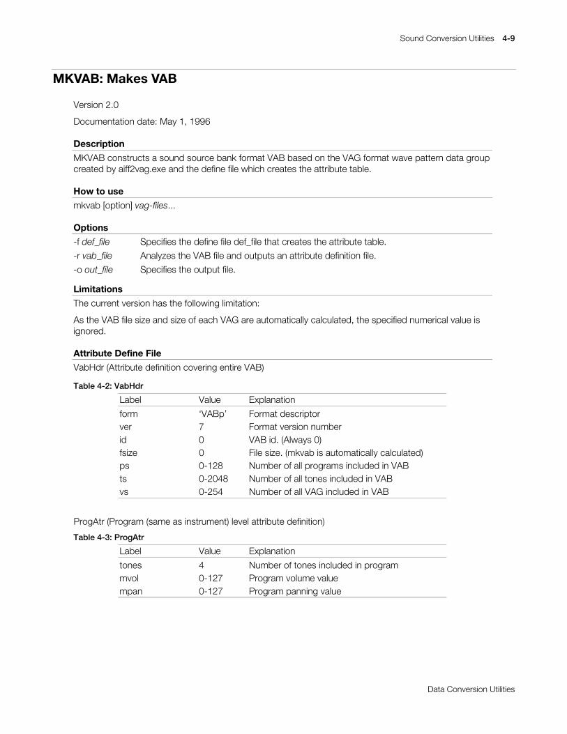
Sound Conversion Utilities 4-9
Printed:11/19/98 4:17 PM By:SCEA Filename:final44Dataconv.doc Last saved by:SONY On:11/19/98 3:28 PM Comments: Master Copy, TechRef Release 4.3.
Data Conversion Utilities
MKVAB: Makes VAB
Version 2.0
Documentation date: May 1, 1996
Description
MKVAB constructs a sound source bank format VAB based on the VAG format wave pattern data groupcreated by aiff2vag.exe and the define file which creates the attribute table.
How to use
mkvab [option] vag-files...
Options
-f def_file Specifies the define file def_file that creates the attribute table.
-r vab_file Analyzes the VAB file and outputs an attribute definition file.
-o out_file Specifies the output file.
Limitations
The current version has the following limitation:
As the VAB file size and size of each VAG are automatically calculated, the specified numerical value isignored.
Attribute Define File
VabHdr (Attribute definition covering entire VAB)
Table 4-2: VabHdr
Label Value Explanation
form ‘VABp’ Format descriptorver 7 Format version numberid 0 VAB id. (Always 0)fsize 0 File size. (mkvab is automatically calculated)ps 0-128 Number of all programs included in VABts 0-2048 Number of all tones included in VABvs 0-254 Number of all VAG included in VAB
ProgAtr (Program (same as instrument) level attribute definition)
Table 4-3: ProgAtr
Label Value Explanation
tones 4 Number of tones included in programmvol 0-127 Program volume valuempan 0-127 Program panning value

4-10 Sound Conversion Utilities
Printed:11/19/98 4:17 PM By:SCEA Filename:final44Dataconv.doc Last saved by:SONY On:11/19/98 3:28 PM Comments: Master Copy, TechRef Release 4.3.
Data Conversion Utilities
VagAtr (Tone level attribute definition)
Table 4-4: VagAtr
Label Value Explanation
prior 0-127 Tone priority level. Larger value takes precedence.mode 0,4 When set to 4, reverb effect is possible.*vol 0-127 Tone volume value.pan 0-127 Tone panning valuecenter 0-127 Center note (half sound units)shift 0-127 Center note fine tuningmin 0-127 Minimum value of note remitmax 0-127 Maximum value of note remitpbmin 0-127 Minimum value of pitch bend in lower directionpbmax 0-127 Maximum value of pitch bend in lower directionar 0-127 Attack ratedr 0-15 Decay ratesr 0-127 Sustain raterr 0-31 Release ratesl 0-15 Sustain levelprog 0-127 Program number attached to the tonevag 0-254 VAG in use
* Special sound functions must be set in the reverb settings to obtain reverb effects.
Supplement
The rates for the ADSR (envelope), namely, attack, decay, sustain and release can be individually set, andby such timely changes the linear and exponential functions can be specified. It is also possible to set thesustain level.
Figure 4-7: ADSR rates
.H\ýRQ .H\ýRII
6/
'5$5
6555
DWWDFN GHFD\ UHOHDVHVXVWDLQ
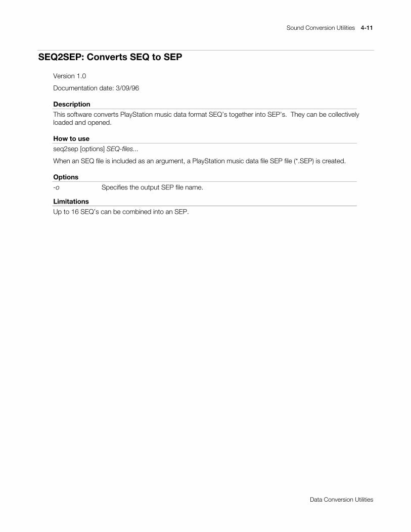
Sound Conversion Utilities 4-11
Printed:11/19/98 4:17 PM By:SCEA Filename:final44Dataconv.doc Last saved by:SONY On:11/19/98 3:28 PM Comments: Master Copy, TechRef Release 4.3.
Data Conversion Utilities
SEQ2SEP: Converts SEQ to SEP
Version 1.0
Documentation date: 3/09/96
Description
This software converts PlayStation music data format SEQ’s together into SEP’s. They can be collectivelyloaded and opened.
How to use
seq2sep [options] SEQ-files...
When an SEQ file is included as an argument, a PlayStation music data file SEP file (*.SEP) is created.
Options
-o Specifies the output SEP file name.
Limitations
Up to 16 SEQ’s can be combined into an SEP.

4-12 Sound Conversion Utilities
Printed:11/19/98 4:17 PM By:SCEA Filename:final44Dataconv.doc Last saved by:SONY On:11/19/98 3:28 PM Comments: Master Copy, TechRef Release 4.3.
Data Conversion Utilities
VABSPLIT: Splits VAB into VH and VB
Version 2.0
Documentation date: 5/1/96
Description
This software divides the PlayStation sound source bank data (VAB) created by mkvab.exe into an attributetable section (VH) and a wave pattern data section (VB). Although the VH data must exist in the mainmemory when music is playing, this is not the case if the VB data is transferred to the SPU once.
How to use
vabsplit vab-files...
When the VAB data is included as an argument, it is divided into a PS sound source bank attribute tablesection and a wave pattern data section. If multiple files are included, they can be all converted together.The file extension can be shortened to [.vab].
Options
None
Constraints
None
When music is playing multiple files are included, they can all be converted together. This file extension canbe shortened to VAB.
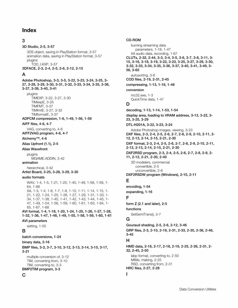
Printed:11/19/98 4:17 PM By:SCEA Filename:final44Dataconv.doc Last saved by:SONY On:11/19/98 3:28 PM Comments: Master Copy, TechRef Release 4.3.
Data Conversion Utilities
Index
33D Studio, 2-5, 3-57
3DS object, saving in PlayStation format, 3-57animation data, saving in PlayStation format, 3-57plugins
TOD_I.KXP, 3-573DFACE, 2-3, 2-4, 2-5, 2-6, 2-12, 2-15
AAdobe Photoshop, 3-3, 3-5, 3-22, 3-23, 3-24, 3-25, 3-27, 3-28, 3-29, 3-30, 3-31, 3-32, 3-33, 3-34, 3-35, 3-36,3-37, 3-39, 3-40, 3-41
pluginsTIMEXP, 3-22, 3-27, 3-30TIMexpE, 3-25TIMFMT, 3-37TIMfmtE, 3-27, 3-32TIMformatE, 3-37
ADPCM compression, 1-6, 1-49, 1-56, 1-59
AIFF files, 4-6, 4-7
VAG, converting to, 4-6AIFF2VAG program, 4-6, 4-7
Alchemy™, 4-6
Alias Upfront (1.1), 2-5
Alias Wavefront
pluginsMGAME.ADDIN, 3-42
animation
hierarchical, 3-42Artist Board, 3-25, 3-28, 3-29, 3-30
audio formats
WAV, 1-4, 1-5, 1-21, 1-25, 1-40, 1-49, 1-58, 1-59, 1-64, 1-66XA, 1-3, 1-4, 1-6, 1-7, 1-8, 1-10, 1-11, 1-14, 1-15, 1-21, 1-22, 1-24, 1-25, 1-26, 1-27, 1-29, 1-31, 1-33, 1-34, 1-37, 1-38, 1-40, 1-41, 1-42, 1-43, 1-44, 1-45, 1-47, 1-49, 1-54, 1-56, 1-59, 1-60, 1-61, 1-63, 1-64, 1-65, 1-67, 1-68
AVI format, 1-4, 1-18, 1-20, 1-24, 1-25, 1-26, 1-27, 1-28,1-32, 1-36, 1-47, 1-48, 1-49, 1-55, 1-58, 1-59, 1-60, 1-61
AVI parameters
setting, 1-55
Bbatch conversions, 1-24
binary data, 2-16
BMP files, 3-3, 3-7, 3-10, 3-12, 3-13, 3-14, 3-15, 3-17,3-21
multiple conversion of, 3-12TIM, converting from, 3-10TIM, converting to, 3-3
BMP2TIM program, 3-3
C
CD-ROM
burning streaming dataparameters, 1-18, 1-47
XA audio data, recording, 1-67CLUTs, 2-32, 2-44, 3-3, 3-4, 3-5, 3-6, 3-7, 3-8, 3-11, 3-15, 3-16, 3-18, 3-19, 3-22, 3-23, 3-25, 3-27, 3-29, 3-30,3-32, 3-33, 3-34, 3-35, 3-36, 3-37, 3-40, 3-41, 3-49, 3-56, 3-65
autosorting, 3-6COD files, 2-19, 2-31, 2-45
compressing, 1-13, 1-16, 1-48
conversion
mc32.exe, 1-3QuickTime data, 1-47
Ddecoding, 1-13, 1-14, 1-53, 1-54
display area, loading to VRAM address, 3-13, 3-22, 3-23, 3-25, 3-29
DTL-H201A, 3-22, 3-23, 3-24
Adobe Photoshop images, viewing, 3-23DXF files, 2-3, 2-4, 2-5, 2-6, 2-7, 2-8, 2-9, 2-10, 2-11, 2-12, 2-13, 2-14, 2-15, 2-21, 2-30
DXF format, 2-3, 2-4, 2-5, 2-6, 2-7, 2-8, 2-9, 2-10, 2-11,2-12, 2-13, 2-14, 2-15, 2-21, 2-30
DXF2RSD program, 2-3, 2-4, 2-5, 2-6, 2-7, 2-8, 2-9, 2-11, 2-12, 2-21, 2-30, 2-40
3D modelers, commercialconvertible, 2-5unconvertible, 2-6
DXF2RSDW program (Windows), 2-10, 2-11
Eencoding, 1-54
expanding, 1-16
Fform Z (2.1 and later), 2-5
functions
SetSemiTrans(), 3-7
GGouraud shading, 2-5, 2-6, 2-12, 3-46
GRP files, 2-3, 2-10, 2-19, 2-31, 2-33, 2-35, 2-36, 2-46,3-45
HHMD data, 2-16, 2-17, 2-18, 2-19, 2-25, 2-26, 2-31, 2-32, 2-45, 2-50
labp format, converting to, 2-50MIMe, making, 2-25RSD, converting from, 2-31
HRC files, 2-27, 2-28
I
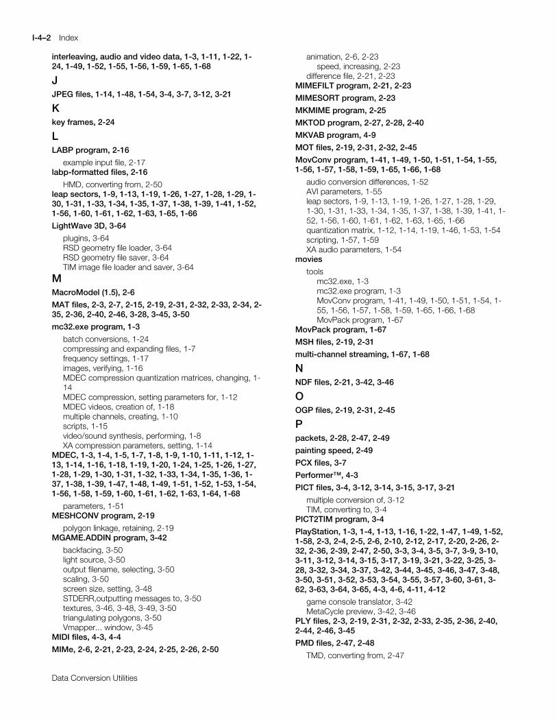
I-4–2 Index
Printed:11/19/98 4:17 PM By:SCEA Filename:final44Dataconv.doc Last saved by:SONY On:11/19/98 3:28 PM Comments: Master Copy, TechRef Release 4.3.
Data Conversion Utilities
interleaving, audio and video data, 1-3, 1-11, 1-22, 1-24, 1-49, 1-52, 1-55, 1-56, 1-59, 1-65, 1-68
JJPEG files, 1-14, 1-48, 1-54, 3-4, 3-7, 3-12, 3-21
Kkey frames, 2-24
LLABP program, 2-16
example input file, 2-17labp-formatted files, 2-16
HMD, converting from, 2-50leap sectors, 1-9, 1-13, 1-19, 1-26, 1-27, 1-28, 1-29, 1-30, 1-31, 1-33, 1-34, 1-35, 1-37, 1-38, 1-39, 1-41, 1-52,1-56, 1-60, 1-61, 1-62, 1-63, 1-65, 1-66
LightWave 3D, 3-64
plugins, 3-64RSD geometry file loader, 3-64RSD geometry file saver, 3-64TIM image file loader and saver, 3-64
MMacroModel (1.5), 2-6
MAT files, 2-3, 2-7, 2-15, 2-19, 2-31, 2-32, 2-33, 2-34, 2-35, 2-36, 2-40, 2-46, 3-28, 3-45, 3-50
mc32.exe program, 1-3
batch conversions, 1-24compressing and expanding files, 1-7frequency settings, 1-17images, verifying, 1-16MDEC compression quantization matrices, changing, 1-14MDEC compression, setting parameters for, 1-12MDEC videos, creation of, 1-18multiple channels, creating, 1-10scripts, 1-15video/sound synthesis, performing, 1-8XA compression parameters, setting, 1-14
MDEC, 1-3, 1-4, 1-5, 1-7, 1-8, 1-9, 1-10, 1-11, 1-12, 1-13, 1-14, 1-16, 1-18, 1-19, 1-20, 1-24, 1-25, 1-26, 1-27,1-28, 1-29, 1-30, 1-31, 1-32, 1-33, 1-34, 1-35, 1-36, 1-37, 1-38, 1-39, 1-47, 1-48, 1-49, 1-51, 1-52, 1-53, 1-54,1-56, 1-58, 1-59, 1-60, 1-61, 1-62, 1-63, 1-64, 1-68
parameters, 1-51MESHCONV program, 2-19
polygon linkage, retaining, 2-19MGAME.ADDIN program, 3-42
backfacing, 3-50light source, 3-50output filename, selecting, 3-50scaling, 3-50screen size, setting, 3-48STDERR,outputting messages to, 3-50textures, 3-46, 3-48, 3-49, 3-50triangulating polygons, 3-50Vmapper... window, 3-45
MIDI files, 4-3, 4-4
MIMe, 2-6, 2-21, 2-23, 2-24, 2-25, 2-26, 2-50
animation, 2-6, 2-23speed, increasing, 2-23
difference file, 2-21, 2-23MIMEFILT program, 2-21, 2-23
MIMESORT program, 2-23
MKMIME program, 2-25
MKTOD program, 2-27, 2-28, 2-40
MKVAB program, 4-9
MOT files, 2-19, 2-31, 2-32, 2-45
MovConv program, 1-41, 1-49, 1-50, 1-51, 1-54, 1-55,1-56, 1-57, 1-58, 1-59, 1-65, 1-66, 1-68
audio conversion differences, 1-52AVI parameters, 1-55leap sectors, 1-9, 1-13, 1-19, 1-26, 1-27, 1-28, 1-29,1-30, 1-31, 1-33, 1-34, 1-35, 1-37, 1-38, 1-39, 1-41, 1-52, 1-56, 1-60, 1-61, 1-62, 1-63, 1-65, 1-66quantization matrix, 1-12, 1-14, 1-19, 1-46, 1-53, 1-54scripting, 1-57, 1-59XA audio parameters, 1-54
movies
toolsmc32.exe, 1-3mc32.exe program, 1-3MovConv program, 1-41, 1-49, 1-50, 1-51, 1-54, 1-55, 1-56, 1-57, 1-58, 1-59, 1-65, 1-66, 1-68MovPack program, 1-67
MovPack program, 1-67
MSH files, 2-19, 2-31
multi-channel streaming, 1-67, 1-68
NNDF files, 2-21, 3-42, 3-46
OOGP files, 2-19, 2-31, 2-45
Ppackets, 2-28, 2-47, 2-49
painting speed, 2-49
PCX files, 3-7
Performer™, 4-3
PICT files, 3-4, 3-12, 3-14, 3-15, 3-17, 3-21
multiple conversion of, 3-12TIM, converting to, 3-4
PICT2TIM program, 3-4
PlayStation, 1-3, 1-4, 1-13, 1-16, 1-22, 1-47, 1-49, 1-52,1-58, 2-3, 2-4, 2-5, 2-6, 2-10, 2-12, 2-17, 2-20, 2-26, 2-32, 2-36, 2-39, 2-47, 2-50, 3-3, 3-4, 3-5, 3-7, 3-9, 3-10,3-11, 3-12, 3-14, 3-15, 3-17, 3-19, 3-21, 3-22, 3-25, 3-28, 3-32, 3-34, 3-37, 3-42, 3-44, 3-45, 3-46, 3-47, 3-48,3-50, 3-51, 3-52, 3-53, 3-54, 3-55, 3-57, 3-60, 3-61, 3-62, 3-63, 3-64, 3-65, 4-3, 4-6, 4-11, 4-12
game console translator, 3-42MetaCycle preview, 3-42, 3-46
PLY files, 2-3, 2-19, 2-31, 2-32, 2-33, 2-35, 2-36, 2-40,2-44, 2-46, 3-45
PMD files, 2-47, 2-48
TMD, converting from, 2-47
Sound Conversion Utilities 4–3
Printed:11/19/98 4:17 PM By:SCEA Filename:final44Dataconv.doc Last saved by:SONY On:11/19/98 3:28 PM Comments: Master Copy, TechRef Release 4.3.
Data Conversion Utilities
POLYFACE MESH, 2-5
polygon linkage, retaining, 2-19
Polyline, 2-4, 2-5, 2-12, 2-15
PRJ files, 2-27, 2-28, 2-39, 2-42, 3-62, 3-63
PVT files, 2-19, 2-31, 2-45
QQuickTime data, 1-47
conversion, 1-47
RRGB files, 1-4, 1-5, 1-18, 1-25, 1-33, 1-34, 1-35, 1-36, 1-48, 1-49, 1-58, 1-59, 1-63, 1-64, 2-7, 2-15, 3-5, 3-7, 3-12, 3-14, 3-15, 3-17, 3-18, 3-23, 3-27, 3-29, 3-30, 3-33,3-34, 3-35, 3-36, 3-40, 3-64, 3-65
multiple conversion of, 3-12TIM, converting to, 3-5
RGB format, 1-4, 1-5, 1-18, 1-25, 1-33, 1-34, 1-35, 1-36,1-48, 1-49, 1-58, 1-59, 1-63, 1-64, 2-7, 2-15, 3-5, 3-7, 3-12, 3-14, 3-15, 3-17, 3-18, 3-23, 3-27, 3-29, 3-30, 3-33,3-34, 3-35, 3-36, 3-40, 3-64, 3-65
RGB2TIM program, 3-5
RSD file set, 2-33
RSD files, 2-3, 2-5, 2-6, 2-7, 2-9, 2-10, 2-14, 2-15, 2-19,2-21, 2-27, 2-28, 2-30, 2-31, 2-32, 2-33, 2-35, 2-36, 2-37, 2-38, 2-39, 2-40, 2-41, 2-43, 2-44, 2-45, 2-46, 3-13,3-17, 3-45, 3-52, 3-57, 3-58, 3-61, 3-62, 3-63, 3-64
RSD format (PlayStation 3D model data format), 2-3, 2-5, 2-6, 2-7, 2-9, 2-10, 2-14, 2-15, 2-19, 2-21, 2-27, 2-28,2-30, 2-31, 2-32, 2-33, 2-35, 2-36, 2-37, 2-38, 2-39, 2-40, 2-41, 2-43, 2-44, 2-45, 2-46, 3-13, 3-17, 3-45, 3-52,3-57, 3-58, 3-61, 3-62, 3-63, 3-64
deforming or moving data, 2-35DXF, converting from, 2-3, 2-10DXF, converting to, 2-30HMD, converting to, 2-31mulitiple files, linking, 2-33old RSD files, creating HMD-compatible files from, 2-45TMD, converting to, 2-39
RSD2DXF program, 2-30
RSD2HMD program, 2-31
RSDCAT program, 2-33
RSDFORM program, 2-27, 2-35, 2-36, 2-37, 2-40
RSDLINK program, 2-21, 2-27, 2-36, 2-39, 2-40, 2-41,2-42, 2-43, 2-44, 3-61
RSDUP program, 2-45
Sscript files, 1-15, 1-17, 1-24, 1-59, 3-53
scripting functions
Avi2bsAv(), 1-25, 1-27Avi2bsC(), 1-25, 1-28Avi2bsV(), 1-25, 1-28Avi2strMdecAv(), 1-25, 1-26, 1-59, 1-60Avi2strMdecC(), 1-25, 1-27, 1-59, 1-61Avi2strMdecV(), 1-25, 1-26, 1-59, 1-60MakeAv(), 1-25, 1-40, 1-41, 1-59, 1-65, 1-66MakeV(), 1-25, 1-41, 1-59, 1-66
Pack16ch(), 1-25, 1-45Pack1ch(), 1-25, 1-42Pack2ch(), 1-25, 1-42, 1-43Pack32ch(), 1-25, 1-45, 1-46Pack4xh(), 1-25Pack8ch(), 1-25, 1-44Pcm2xa(), 1-25, 1-40, 1-59, 1-65Rgb2Avi(), 1-25, 1-36, 1-59Rgb2bsAv(), 1-25, 1-34, 1-35Rgb2bsC(), 1-25, 1-36, 1-59Rgb2bsV(), 1-25, 1-35, 1-59Rgb2strMdecAv(), 1-25, 1-33, 1-59, 1-63Rgb2strMdecC(), 1-25, 1-34, 1-59, 1-64Rgb2strMdecV(), 1-25, 1-33, 1-34, 1-59, 1-63, 1-64SetDefaultQ(), 1-25, 1-47SetQ(), 1-25, 1-46Tim2bsAv(), 1-25, 1-38Tim2bsC(), 1-25, 1-39, 1-59Tim2bsV(), 1-25, 1-39, 1-59Tim2strMdecAv(), 1-25, 1-37Tim2strMdecC(), 1-25, 1-38Tim2strMdecV(), 1-25, 1-37Wav2xa(), 1-25, 1-40, 1-59, 1-64Yuv2Avi(), 1-25, 1-32Yuv2bsAv(), 1-25, 1-31Yuv2bsC(), 1-25, 1-32, 1-59Yuv2bsV(), 1-25, 1-31, 1-32, 1-59Yuv2strMdecAv(), 1-25, 1-29, 1-59, 1-61Yuv2strMdecC(), 1-25, 1-30, 1-59, 1-62Yuv2strMdecV(), 1-25, 1-30, 1-59, 1-62
Sculptura (1.1), 2-5
SEP files, 4-11
SEQ, converting from, 4-11SEQ files, 4-3, 4-11
SEP, converting to, 4-11SEQ format (sequence data format), 4-3, 4-11
SEQ2SEP program, 4-11
sequence data, creating, 4-3
ShadeIII (1.0), 2-6
SMF format, 4-3, 4-4
SMF2SEQ program, 4-3, 4-4
Sound Artist Tool (DTL-S710), vii
SoundDesigner II™, 4-6
STP (SemiTransparent information), 3-7, 3-8, 3-22, 3-25, 3-27, 3-29, 3-32, 3-33, 3-35, 3-37, 3-49, 3-55
bits, 3-7, 3-8, 3-27, 3-29, 3-33, 3-35, 3-49, 3-55controlling, 3-42, 3-49
Strata Studio Pro (1.0), 2-5
StrataVision, 2-5
streaming
multi-channel, 1-67, 1-68streaming data, 1-3, 1-11, 1-13, 1-21, 1-22, 1-23, 1-24,1-47, 1-48, 1-52, 1-67, 1-68
managingMovPack program, 1-67
streaming format (STR), 1-4, 1-5, 1-8, 1-9, 1-10, 1-11, 1-16, 1-19, 1-24, 1-25, 1-26, 1-27, 1-29, 1-30, 1-33, 1-34,
I-4–4 Index
Printed:11/19/98 4:17 PM By:SCEA Filename:final44Dataconv.doc Last saved by:SONY On:11/19/98 3:28 PM Comments: Master Copy, TechRef Release 4.3.
Data Conversion Utilities
1-37, 1-38, 1-42, 1-43, 1-44, 1-45, 1-47, 1-49, 1-51, 1-56, 1-58, 1-59, 1-60, 1-61, 1-62, 1-63, 1-64, 1-68
Streaming format (STR)
MDEC, 1-3, 1-4, 1-5, 1-7, 1-8, 1-9, 1-10, 1-11, 1-12, 1-13, 1-14, 1-16, 1-18, 1-19, 1-20, 1-24, 1-25, 1-26, 1-27, 1-28, 1-29, 1-30, 1-31, 1-32, 1-33, 1-34, 1-35, 1-36, 1-37, 1-38, 1-39, 1-47, 1-48, 1-49, 1-51, 1-52, 1-53, 1-54, 1-56, 1-58, 1-59, 1-60, 1-61, 1-62, 1-63, 1-64, 1-68
Ttexture CLUT, loading to VRAM address, 3-22, 3-23, 3-25, 3-27, 3-29, 3-32, 3-37, 3-39
texture mapping, 3-16, 3-22, 3-25, 3-31, 3-64
texture page, loading to VRAM address, 3-20, 3-22, 3-23, 3-25, 3-29, 3-32, 3-37, 3-39
TIFF files, 3-7
TIM format, 1-4, 1-5, 1-25, 1-37, 1-38, 1-39, 1-49, 1-58,1-59, 2-28, 2-31, 2-32, 2-40, 2-45, 2-46, 3-3, 3-4, 3-5, 3-6, 3-7, 3-8, 3-9, 3-10, 3-11, 3-12, 3-13, 3-14, 3-15, 3-16,3-17, 3-18, 3-19, 3-21, 3-22, 3-23, 3-27, 3-28, 3-31, 3-32, 3-33, 3-34, 3-35, 3-36, 3-37, 3-38, 3-39, 3-40, 3-41,3-45, 3-46, 3-52, 3-53, 3-55, 3-56, 3-64, 3-65
Adobe Photoshop, exporting images, 3-32, 3-37Adobe Photoshop, importing images, 3-32, 3-37BMP, converting from, 3-3, 3-7BMP, converting to, 3-10JPEG, converting from, 3-7load time, speeding up, 3-9multiple conversion of, 3-12pallet (CLUT) addressess, changing, 3-11PCX, converting from, 3-7PICT, converting from, 3-4RGB, converting from, 3-5STP bit, controlling, 3-42, 3-49TIFF, converting from, 3-7TIMTOOL, 3-6VRAM, changing, 3-11
TIM2BMP program, 3-10
TIMEXP program, 3-22, 3-27, 3-30
TIMexpE program, 3-25
TIMFMT program, 3-37
TIMfmtE program, 3-27, 3-32
TIMformatE program, 3-37
TIMPOS program, 3-11, 3-17, 3-21
TIMTOOL program, 3-6
TIMUTIL program, 3-12
pallet for display, setting, 3-16parameter settings, 2-11, 3-14screen resolution, setting, 3-16VRAM position, setting, 3-16
TMD files, 2-21, 2-23, 2-24, 2-25, 2-27, 2-28, 2-36, 2-39,2-40, 2-41, 2-42, 2-43, 2-44, 2-47, 2-48, 2-49, 3-42, 3-45, 3-46, 3-50, 3-52, 3-58, 3-60, 3-61
PMD, converting to, 2-47sorting and displaying, 2-49vertex information, sorting, 2-23
TMD2PMD program, 2-47
TMDINFO program, 2-49
TMDSORT program, 2-49
TOD files, 2-27, 2-28, 2-36, 2-40, 3-42, 3-45, 3-46, 3-50,3-52, 3-55, 3-57, 3-58, 3-59, 3-60, 3-61, 3-62, 3-63
TOD_I.KXP program, 3-57
trueSpace (1.0), 2-5
VVAB data, 4-9, 4-12
VH and VB, splitting into, 4-12VAB files, 4-9, 4-12
VABSPLIT program, 4-12
VAG files, 4-6, 4-7, 4-9, 4-10
AIFF, converting from, 4-6VAG format, 4-6, 4-7, 4-9, 4-10
VB data, 4-12
VDF files, 2-21, 2-22, 3-42, 3-46
vertex information, sorting, 2-23
VH data, 4-12
video capture board, 1-18, 1-48
video data conversion
MovConv program, 1-41, 1-49, 1-50, 1-51, 1-54, 1-55,1-56, 1-57, 1-58, 1-59, 1-65, 1-66, 1-68
Vision™, 4-3
WWAV audio format, 1-4, 1-5, 1-21, 1-25, 1-40, 1-49, 1-58, 1-59, 1-64, 1-66
waveform data, creating, 4-6
Windows 3.1, 1-3
Windows 95, 1-3, 3-25, 3-32, 3-52
XA audio format, 1-3, 1-4, 1-6, 1-7, 1-8, 1-10, 1-11, 1-14, 1-15, 1-21, 1-22, 1-24, 1-25, 1-26, 1-27, 1-29, 1-31,1-33, 1-34, 1-37, 1-38, 1-40, 1-41, 1-42, 1-43, 1-44, 1-45, 1-47, 1-49, 1-54, 1-56, 1-59, 1-60, 1-61, 1-63, 1-64,1-65, 1-67, 1-68
parameters, 1-54
XXHMD program, 2-50
YYUV format, 1-4, 1-5, 1-18, 1-25, 1-29, 1-30, 1-31, 1-32,1-48, 1-49, 1-58, 1-59, 1-61, 1-62