Embed Size (px)
Citation preview
Standard Data Format Utilities
User’s Guide
Version B.02.01
H
HP Part Number 5963-1715
Printed in U.S.A.Print Date: December 1994
Hewlett-Packard Company, 1989, 1991-94. All rights reserved.8600 Soper Hill Road, Everett, WA 98205-1298


Registration Card
Make sure you send in the product registration card located in the red brochureincluded in your SDF Utilities shipping carton. This assures that you will hearabout future SDF Utilities product and service updates. If the brochure has beenmisplaced, simply mail or fax the following information to the indicatedaddress/fax number.
Your Name:Position:Company Name:Division:Mail Stop:Street:City:State or Province:Postal Code:Country:Telephone: ( )-Instrument Model:Serial Number:
Mail to:
ATTN: Quality and Productivity MS230Hewlett-Packard CompanyLake Stevens Instrument Division8600 Soper Hill Rd.Everett, WA 98205-1298
Or FAX:
(206) 335-2828No cover sheet is required.Quality and Productivity Department MS230

TABLE OF CONTENTS
CHAPTER 1: General Information
Converting Files Between LIF Format and DOS Format . . . . . . . . . . . . . . . . . . 1-4
README.TXT . . . . . . . . . . . . . . . . . . . . . . . . . . . . . . . . . . . . . . . . 1-4
Data Sharing Between Analyzers . . . . . . . . . . . . . . . . . . . . . . . . . . . . . . . 1-5
Batch Files . . . . . . . . . . . . . . . . . . . . . . . . . . . . . . . . . . . . . . . . . . . 1-6
Displaying Analyzer Data on a Personal Computer . . . . . . . . . . . . . . . . . . . . . 1-7
Reading Data from Files into a Program . . . . . . . . . . . . . . . . . . . . . . . . . . . 1-9
Minimum Requirements . . . . . . . . . . . . . . . . . . . . . . . . . . . . . . . . . . . . 1-9
Installation . . . . . . . . . . . . . . . . . . . . . . . . . . . . . . . . . . . . . . . . . . 1-10
CHAPTER 2: What is Standard Data Format?
Measurement (Data) Results . . . . . . . . . . . . . . . . . . . . . . . . . . . . . . . . . 2-2
Number of Input Channels (Rows) . . . . . . . . . . . . . . . . . . . . . . . . . . . . . . 2-3
Waterfalls and Maps (Scans) . . . . . . . . . . . . . . . . . . . . . . . . . . . . . . . . . 2-4
Time Capture (Scans) . . . . . . . . . . . . . . . . . . . . . . . . . . . . . . . . . . . . . 2-5
CHAPTER 3: File System Conversion (LIF/DOS)
Hardware and Software Requirements . . . . . . . . . . . . . . . . . . . . . . . . . . . . 3-2
Online Help . . . . . . . . . . . . . . . . . . . . . . . . . . . . . . . . . . . . . . . . . . 3-3
LIF . . . . . . . . . . . . . . . . . . . . . . . . . . . . . . . . . . . . . . . . . . . . . . . 3-4
LIF SCAN . . . . . . . . . . . . . . . . . . . . . . . . . . . . . . . . . . . . . . . . . . . 3-5
LIF CHK . . . . . . . . . . . . . . . . . . . . . . . . . . . . . . . . . . . . . . . . . . . . 3-7
LIF LS . . . . . . . . . . . . . . . . . . . . . . . . . . . . . . . . . . . . . . . . . . . . . 3-8
LIF CP . . . . . . . . . . . . . . . . . . . . . . . . . . . . . . . . . . . . . . . . . . . . 3-10
LIF RM . . . . . . . . . . . . . . . . . . . . . . . . . . . . . . . . . . . . . . . . . . . . 3-15
LIF INIT . . . . . . . . . . . . . . . . . . . . . . . . . . . . . . . . . . . . . . . . . . . 3-17
LIFDIAG . . . . . . . . . . . . . . . . . . . . . . . . . . . . . . . . . . . . . . . . . . . 3-20
Error Messages . . . . . . . . . . . . . . . . . . . . . . . . . . . . . . . . . . . . . . . . 3-24
CHAPTER 4: Sharing Data Between Analyzers
Hardware and Software Requirements . . . . . . . . . . . . . . . . . . . . . . . . . . . . 4-4
HP 3563A/3562A File Format . . . . . . . . . . . . . . . . . . . . . . . . . . . . . . . . 4-4
Online Help . . . . . . . . . . . . . . . . . . . . . . . . . . . . . . . . . . . . . . . . . . 4-4
i
60TOSDF . . . . . . . . . . . . . . . . . . . . . . . . . . . . . . . . . . . . . . . . . . . 4-5
63TCSDF . . . . . . . . . . . . . . . . . . . . . . . . . . . . . . . . . . . . . . . . . . . . 4-6
63TOSDF . . . . . . . . . . . . . . . . . . . . . . . . . . . . . . . . . . . . . . . . . . . 4-7
660TOSDF . . . . . . . . . . . . . . . . . . . . . . . . . . . . . . . . . . . . . . . . . . . 4-8
69TOSDF . . . . . . . . . . . . . . . . . . . . . . . . . . . . . . . . . . . . . . . . . . . 4-9
88TOSDF . . . . . . . . . . . . . . . . . . . . . . . . . . . . . . . . . . . . . . . . . . 4-11
89TOSDF . . . . . . . . . . . . . . . . . . . . . . . . . . . . . . . . . . . . . . . . . . 4-13
ASCTOSDF . . . . . . . . . . . . . . . . . . . . . . . . . . . . . . . . . . . . . . . . . 4-15
BINTOX32 . . . . . . . . . . . . . . . . . . . . . . . . . . . . . . . . . . . . . . . . . . 4-17
DFDATA63 . . . . . . . . . . . . . . . . . . . . . . . . . . . . . . . . . . . . . . . . . 4-18
DFHDR63 . . . . . . . . . . . . . . . . . . . . . . . . . . . . . . . . . . . . . . . . . . 4-20
DOWNLOAD . . . . . . . . . . . . . . . . . . . . . . . . . . . . . . . . . . . . . . . . 4-22
HEADER63 . . . . . . . . . . . . . . . . . . . . . . . . . . . . . . . . . . . . . . . . . 4-23
HPIB63 . . . . . . . . . . . . . . . . . . . . . . . . . . . . . . . . . . . . . . . . . . . . 4-25
REPEAT . . . . . . . . . . . . . . . . . . . . . . . . . . . . . . . . . . . . . . . . . . . 4-26
SDFEDIT . . . . . . . . . . . . . . . . . . . . . . . . . . . . . . . . . . . . . . . . . . . 4-28
SDFPRINT . . . . . . . . . . . . . . . . . . . . . . . . . . . . . . . . . . . . . . . . . . 4-30
SDFTEXT . . . . . . . . . . . . . . . . . . . . . . . . . . . . . . . . . . . . . . . . . . 4-34
SDFTO58 . . . . . . . . . . . . . . . . . . . . . . . . . . . . . . . . . . . . . . . . . . 4-35
SDFTO63 . . . . . . . . . . . . . . . . . . . . . . . . . . . . . . . . . . . . . . . . . . 4-36
SDFTOASC . . . . . . . . . . . . . . . . . . . . . . . . . . . . . . . . . . . . . . . . . 4-39
SDFTOBIN . . . . . . . . . . . . . . . . . . . . . . . . . . . . . . . . . . . . . . . . . . 4-42
SDFTOML . . . . . . . . . . . . . . . . . . . . . . . . . . . . . . . . . . . . . . . . . . 4-44
SDFTOMX . . . . . . . . . . . . . . . . . . . . . . . . . . . . . . . . . . . . . . . . . . 4-46
SDFTOSDF . . . . . . . . . . . . . . . . . . . . . . . . . . . . . . . . . . . . . . . . . 4-50
SDFYDATA . . . . . . . . . . . . . . . . . . . . . . . . . . . . . . . . . . . . . . . . . 4-54
SETUP63 . . . . . . . . . . . . . . . . . . . . . . . . . . . . . . . . . . . . . . . . . . . 4-55
SETUP88 . . . . . . . . . . . . . . . . . . . . . . . . . . . . . . . . . . . . . . . . . . . 4-57
SETUP89 . . . . . . . . . . . . . . . . . . . . . . . . . . . . . . . . . . . . . . . . . . . 4-59
SOFTCOPY . . . . . . . . . . . . . . . . . . . . . . . . . . . . . . . . . . . . . . . . . 4-61
SYNTH63 . . . . . . . . . . . . . . . . . . . . . . . . . . . . . . . . . . . . . . . . . . 4-62
X32TOBIN . . . . . . . . . . . . . . . . . . . . . . . . . . . . . . . . . . . . . . . . . . 4-64
Error Messages . . . . . . . . . . . . . . . . . . . . . . . . . . . . . . . . . . . . . . . . 4-65
CHAPTER 5: Viewdata
VIEWDATA . . . . . . . . . . . . . . . . . . . . . . . . . . . . . . . . . . . . . . . . . . 5-5
VIEWDATA menu . . . . . . . . . . . . . . . . . . . . . . . . . . . . . . . . . . . . . . . 5-7
File menu (if Type is Auto or HP 3563A/3562A) . . . . . . . . . . . . . . . . . . . . . . . 5-8
File menu (if Type is SDF) . . . . . . . . . . . . . . . . . . . . . . . . . . . . . . . . . . 5-9
Table of Contents
ii
File menu (if Type is ASCII) . . . . . . . . . . . . . . . . . . . . . . . . . . . . . . . . 5-10
Display menu . . . . . . . . . . . . . . . . . . . . . . . . . . . . . . . . . . . . . . . . . 5-11
Active menu . . . . . . . . . . . . . . . . . . . . . . . . . . . . . . . . . . . . . . . . . 5-12
Format menu . . . . . . . . . . . . . . . . . . . . . . . . . . . . . . . . . . . . . . . . . 5-13
Trace menu . . . . . . . . . . . . . . . . . . . . . . . . . . . . . . . . . . . . . . . . . . 5-14
TitleType menu . . . . . . . . . . . . . . . . . . . . . . . . . . . . . . . . . . . . . . . 5-15
TraceData menu . . . . . . . . . . . . . . . . . . . . . . . . . . . . . . . . . . . . . . . 5-16
Grid menu . . . . . . . . . . . . . . . . . . . . . . . . . . . . . . . . . . . . . . . . . . 5-17
Coordinates menu . . . . . . . . . . . . . . . . . . . . . . . . . . . . . . . . . . . . . . 5-18
Xscale menu . . . . . . . . . . . . . . . . . . . . . . . . . . . . . . . . . . . . . . . . . 5-19
Xscale Spacing menu . . . . . . . . . . . . . . . . . . . . . . . . . . . . . . . . . . . . 5-20
Xscale Type menu . . . . . . . . . . . . . . . . . . . . . . . . . . . . . . . . . . . . . . 5-21
Yscale menu . . . . . . . . . . . . . . . . . . . . . . . . . . . . . . . . . . . . . . . . . 5-22
Yscale Type menu . . . . . . . . . . . . . . . . . . . . . . . . . . . . . . . . . . . . . . 5-23
Units menu . . . . . . . . . . . . . . . . . . . . . . . . . . . . . . . . . . . . . . . . . . 5-24
Data menu . . . . . . . . . . . . . . . . . . . . . . . . . . . . . . . . . . . . . . . . . . 5-25
ShowTrace menu . . . . . . . . . . . . . . . . . . . . . . . . . . . . . . . . . . . . . . . 5-26
User Entered Graphics . . . . . . . . . . . . . . . . . . . . . . . . . . . . . . . . . . . . 5-28
User Entered Text . . . . . . . . . . . . . . . . . . . . . . . . . . . . . . . . . . . . . . 5-30
Output menu . . . . . . . . . . . . . . . . . . . . . . . . . . . . . . . . . . . . . . . . . 5-31
Save menu . . . . . . . . . . . . . . . . . . . . . . . . . . . . . . . . . . . . . . . . . . 5-33
CHAPTER 6: Using SDF Data with C Programs
SdfOpen . . . . . . . . . . . . . . . . . . . . . . . . . . . . . . . . . . . . . . . . . . . . 6-3
SdfClose . . . . . . . . . . . . . . . . . . . . . . . . . . . . . . . . . . . . . . . . . . . . 6-4
SdfFileHdr . . . . . . . . . . . . . . . . . . . . . . . . . . . . . . . . . . . . . . . . . . . 6-5
SdfMeasHdr . . . . . . . . . . . . . . . . . . . . . . . . . . . . . . . . . . . . . . . . . . 6-6
SdfDataHdr . . . . . . . . . . . . . . . . . . . . . . . . . . . . . . . . . . . . . . . . . . . 6-7
SdfVectHdr . . . . . . . . . . . . . . . . . . . . . . . . . . . . . . . . . . . . . . . . . . . 6-8
SdfChanHdr . . . . . . . . . . . . . . . . . . . . . . . . . . . . . . . . . . . . . . . . . . 6-9
SdfScanStruct . . . . . . . . . . . . . . . . . . . . . . . . . . . . . . . . . . . . . . . . 6-10
SdfScanBig . . . . . . . . . . . . . . . . . . . . . . . . . . . . . . . . . . . . . . . . . . 6-11
SdfScanVar . . . . . . . . . . . . . . . . . . . . . . . . . . . . . . . . . . . . . . . . . . 6-12
SdfScansUsed . . . . . . . . . . . . . . . . . . . . . . . . . . . . . . . . . . . . . . . . 6-13
SdfYdata . . . . . . . . . . . . . . . . . . . . . . . . . . . . . . . . . . . . . . . . . . . 6-14
SdfYdataWrite . . . . . . . . . . . . . . . . . . . . . . . . . . . . . . . . . . . . . . . . 6-16
SdfXdata . . . . . . . . . . . . . . . . . . . . . . . . . . . . . . . . . . . . . . . . . . . 6-17
SdfScanData . . . . . . . . . . . . . . . . . . . . . . . . . . . . . . . . . . . . . . . . . 6-18
SdfTrunc . . . . . . . . . . . . . . . . . . . . . . . . . . . . . . . . . . . . . . . . . . . 6-19
Table of Contents
iii
SdfCommentHdr . . . . . . . . . . . . . . . . . . . . . . . . . . . . . . . . . . . . . . . 6-20
SdfCommentRead . . . . . . . . . . . . . . . . . . . . . . . . . . . . . . . . . . . . . . 6-21
SdfCommentWrite . . . . . . . . . . . . . . . . . . . . . . . . . . . . . . . . . . . . . . 6-22
CHAPTER 7: MATLAB MEX-Files & M-Files
filtrsdf.mex . . . . . . . . . . . . . . . . . . . . . . . . . . . . . . . . . . . . . . . . . . . 7-2
matdemo.tim . . . . . . . . . . . . . . . . . . . . . . . . . . . . . . . . . . . . . . . . . . 7-3
tcdemo.m . . . . . . . . . . . . . . . . . . . . . . . . . . . . . . . . . . . . . . . . . . . . 7-4
tcdemo2.m . . . . . . . . . . . . . . . . . . . . . . . . . . . . . . . . . . . . . . . . . . . 7-5
CHAPTER 8: Mathcad® Examples
mathcad\signals\ofstsine.mcd . . . . . . . . . . . . . . . . . . . . . . . . . . . . . . . . . 8-1
mathcad\signals\gmsk.mcd . . . . . . . . . . . . . . . . . . . . . . . . . . . . . . . . . . 8-1
mathcad\signals\qpsk.mcd . . . . . . . . . . . . . . . . . . . . . . . . . . . . . . . . . . . 8-2
mathcad\filters\gauss.mcd . . . . . . . . . . . . . . . . . . . . . . . . . . . . . . . . . . . 8-2
mathcad\filters\raiscos.mcd . . . . . . . . . . . . . . . . . . . . . . . . . . . . . . . . . . 8-2
mathcad\filters\rootcos.mcd . . . . . . . . . . . . . . . . . . . . . . . . . . . . . . . . . . 8-2
CHAPTER A: SDF to PC-MATLAB and MATRIXx examples
HP 3563A to MATRIXx or PC-MATLAB file formats . . . . . . . . . . . . . . . . . . . A-2
Loading a File into PC-MATLAB . . . . . . . . . . . . . . . . . . . . . . . . . . . . . . . A-3
Loading a File into MATRIXx . . . . . . . . . . . . . . . . . . . . . . . . . . . . . . . . A-4
CHAPTER B: Standard Data Format (SDF)
Records—the Basic SDF Units . . . . . . . . . . . . . . . . . . . . . . . . . . . . . . . . B-2
Record Order . . . . . . . . . . . . . . . . . . . . . . . . . . . . . . . . . . . . . . . . . . B-3
Special Fields in a Record . . . . . . . . . . . . . . . . . . . . . . . . . . . . . . . . . . . B-5
Record and Structure Descriptions . . . . . . . . . . . . . . . . . . . . . . . . . . . . . . B-6
Reconstructing a Trace . . . . . . . . . . . . . . . . . . . . . . . . . . . . . . . . . . . . B-27
Correcting Y-axis Data . . . . . . . . . . . . . . . . . . . . . . . . . . . . . . . . . . . . B-30
Locating a Vector of Y-axis Data . . . . . . . . . . . . . . . . . . . . . . . . . . . . . . B-34
Time Capture Data . . . . . . . . . . . . . . . . . . . . . . . . . . . . . . . . . . . . . . B-36
Waterfall/Map/MultiSpectrum/Spectrogram Data . . . . . . . . . . . . . . . . . . . . . B-40
Example File . . . . . . . . . . . . . . . . . . . . . . . . . . . . . . . . . . . . . . . . . B-42
CHAPTER C: Batch Files
63_ML.BAT . . . . . . . . . . . . . . . . . . . . . . . . . . . . . . . . . . . . . . . . . . C-2
63_MX.BAT . . . . . . . . . . . . . . . . . . . . . . . . . . . . . . . . . . . . . . . . . . C-3
63_PLOT.BAT . . . . . . . . . . . . . . . . . . . . . . . . . . . . . . . . . . . . . . . . . C-4
63_SDF.BAT . . . . . . . . . . . . . . . . . . . . . . . . . . . . . . . . . . . . . . . . . . C-5
60_ML.BAT . . . . . . . . . . . . . . . . . . . . . . . . . . . . . . . . . . . . . . . . . . C-6
Table of Contents
iv
60_MX.BAT . . . . . . . . . . . . . . . . . . . . . . . . . . . . . . . . . . . . . . . . . . C-7
60_PLOT.BAT . . . . . . . . . . . . . . . . . . . . . . . . . . . . . . . . . . . . . . . . . C-8
60_SDF.BAT . . . . . . . . . . . . . . . . . . . . . . . . . . . . . . . . . . . . . . . . . . C-9
69_ML.BAT . . . . . . . . . . . . . . . . . . . . . . . . . . . . . . . . . . . . . . . . . C-10
69_MX.BAT . . . . . . . . . . . . . . . . . . . . . . . . . . . . . . . . . . . . . . . . . C-11
69_PLOT.BAT . . . . . . . . . . . . . . . . . . . . . . . . . . . . . . . . . . . . . . . . C-12
69_SDF.BAT . . . . . . . . . . . . . . . . . . . . . . . . . . . . . . . . . . . . . . . . . C-13
IB63_ML.BAT . . . . . . . . . . . . . . . . . . . . . . . . . . . . . . . . . . . . . . . . C-14
IB63_MX.BAT . . . . . . . . . . . . . . . . . . . . . . . . . . . . . . . . . . . . . . . . C-15
IB63_PLT.BAT . . . . . . . . . . . . . . . . . . . . . . . . . . . . . . . . . . . . . . . C-16
IB63_SDF.BAT . . . . . . . . . . . . . . . . . . . . . . . . . . . . . . . . . . . . . . . C-17
Table of Contents
v

1
General Information
Introduction
Standard Data Format Utilities is a group of MS-DOS® programs for doing thefollowing things (see figure 1-1, on the following page):
• Converting files between LIF format and DOS format.• Sharing data between HP DSA analyzers.• Displaying analyzer data on your PC.• Reading data from files into a program.
(MS-DOS is a U.S. registered trademark of Microsoft Corporation)
1-1
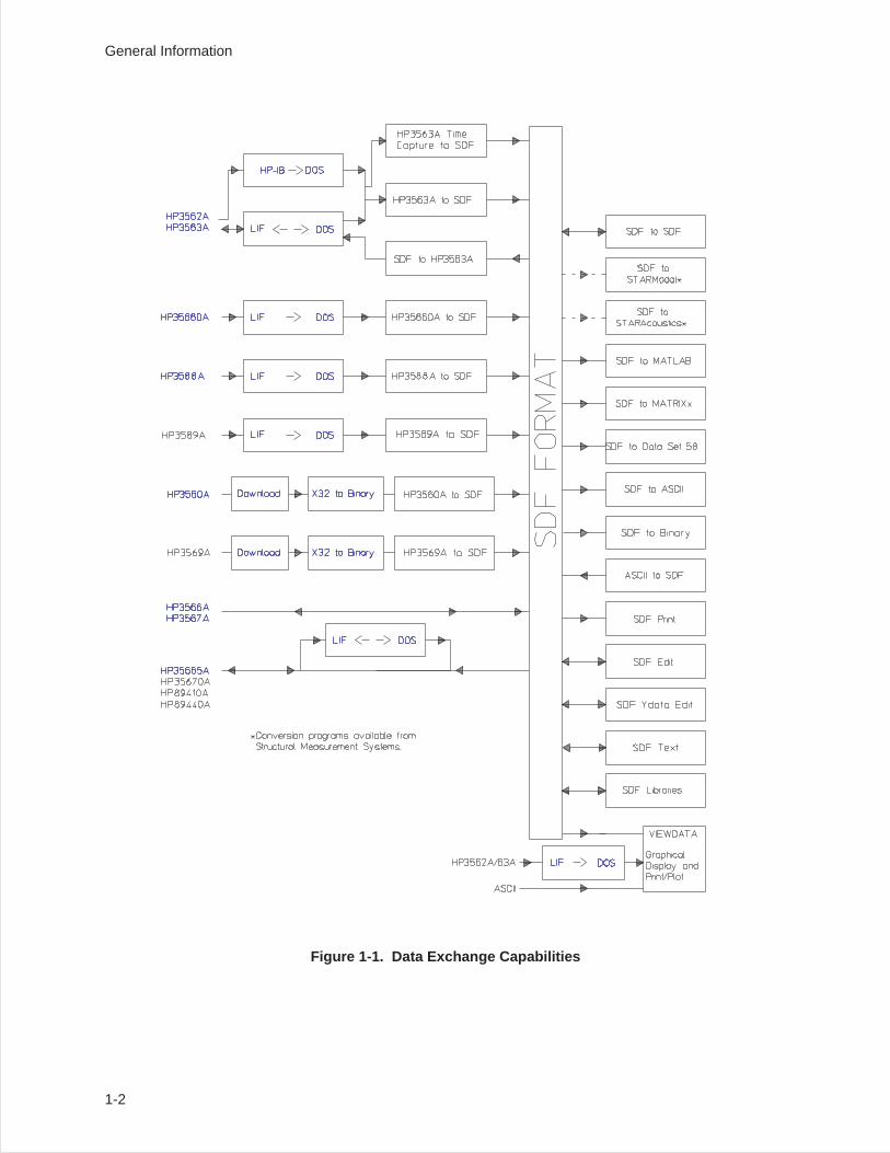
Figure 1-1. Data Exchange Capabilities
General Information
1-2
Notice in figure 1-1 that the data from some analyzers, such as the HP 3563A, must be converted firstfrom LIF to DOS, then to SDF format. For some other analyzers, such as the HP 3566A, no conversionsare necessary—these analysers save data in SDF format directly.
The Standard Data Format Utilities support saved data from the following DSA analyzers:
• HP 35665A (to and from)
• HP 35670A (to and from)
• HP 3562A (to and from)
• HP 3563A (to and from)
• HP 3566A/3567A (to and from)
• HP 35660A (from only)
• HP 3560A (from only)
• HP 3569A (from only)
• HP 3588A (from only)
• HP 3589A (from only)
• HP 89410A/HP89440A (to and from)
• HP 3587S (time capture files only)
There are some limitations on data exchange. For example, order tracking data from anHP 3567A cannot be post-processed in an HP 3563A because the HP 3563A does not doorder tracking measurements.
The Standard Data Format Utilities also allow you to translate data files to the following formatscompatible with third party software:
• PC-MATLAB, a trademark of The MathWorks, Inc., is a software package for general digitalsignal processing and filtering.
• MATRIXx, a product of Integrated Systems Inc., is a software package for controlsystem analysis.
• Data Set 58 is the universal ASCII format for mechanical test.
• ASCII is a versatile format for spreadsheets and other general software.
Programs that convert from Standard Data Format to SMS formats are available from SMS for use withthe following application software:
• STARModal, a trademark of SMS, is a software package for doing modal analysis of structures,including structural modification and force/response analysis.
• STARAcoustics, a trademark of SMS, is an acoustics software package with 1/3 octave, soundintensity, and sound power analysis.
General Information
1-3
Converting Files Between LIF Format and DOS Format
LIF (Logical Interchange Format) is the Hewlett-Packard standard disk format that may be used toexchange files among various HP computer systems and instruments. The LIF programs in the StandardData Format Utilities make it possible for personal computer users to translate LIF files into DOS fileformat, and DOS files into LIF format. The utilities support file conversion for both internal drives andexternal drives connected on the HP-IB. These utilities can also format and initialize LIF disks onexternal HP drives.
README.TXT
This text file, shipped on the SDF UTILITIES disk 1, provides additional information about SDFUTILITIES. Read and/or print the contents of README.TXT as you do with an ASCII text file.
General InformationConverting Files Between LIF Format and DOS Format
1-4
Data Sharing Between Analyzers
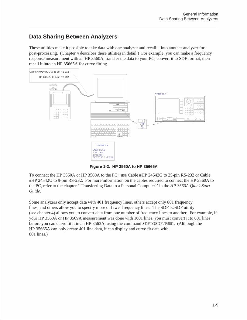
These utilities make it possible to take data with one analyzer and recall it into another analyzer forpost-processing. (Chapter 4 describes these utilities in detail.) For example, you can make a frequencyresponse measurement with an HP 3560A, transfer the data to your PC, convert it to SDF format, thenrecall it into an HP 35665A for curve fitting.
Figure 1-2. HP 3560A to HP 35665A
To connect the HP 3560A or HP 3560A to the PC: use Cable #HP 24542G to 25-pin RS-232 or Cable#HP 24542U to 9-pin RS-232. For more information on the cables required to connect the HP 3560A tothe PC, refer to the chapter ‘’Transferring Data to a Personal Computer’’ in theHP 3560A Quick StartGuide.
Some analyzers only accept data with 401 frequency lines, others accept only 801 frequencylines, and others allow you to specify more or fewer frequency lines. The SDFTOSDF utility(see chapter 4) allows you to convert data from one number of frequency lines to another. For example, ifyour HP 3560A or HP 3569A measurement was done with 1601 lines, you must convert it to 801 linesbefore you can curve fit it in an HP 3563A, using the commandSDFTOSDF /P:801.(Although theHP 35665A can only create 401 line data, it can display and curve fit data with801 lines.)
Cable # HP24542G to 25 pin RS 232
HP 24542U to 9-pin RS 232
General InformationData Sharing Between Analyzers
1-5
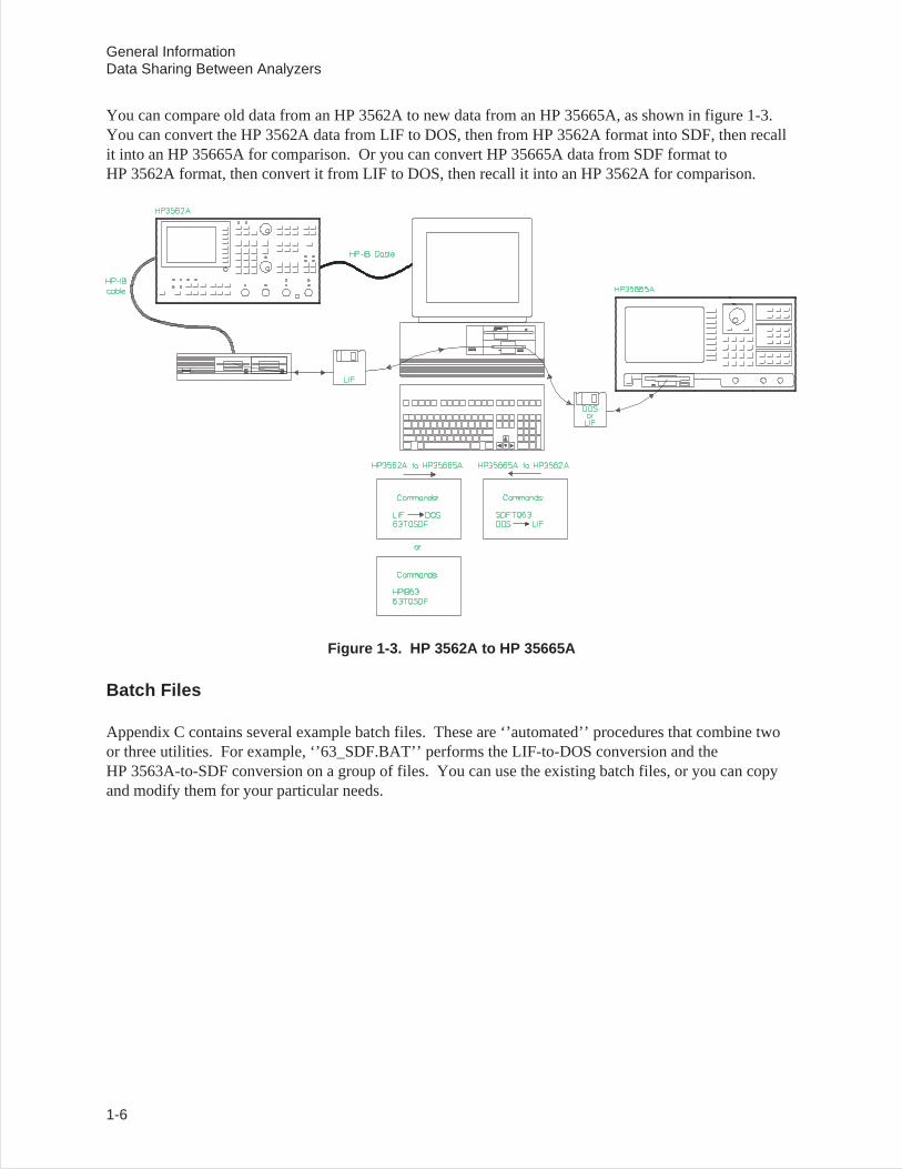
You can compare old data from an HP 3562A to new data from an HP 35665A, as shown in figure 1-3.You can convert the HP 3562A data from LIF to DOS, then from HP 3562A format into SDF, then recallit into an HP 35665A for comparison. Or you can convert HP 35665A data from SDF format toHP 3562A format, then convert it from LIF to DOS, then recall it into an HP 3562A for comparison.
Figure 1-3. HP 3562A to HP 35665A
Batch Files
Appendix C contains several example batch files. These are ‘’automated’’ procedures that combine twoor three utilities. For example, ‘’63_SDF.BAT’’ performs the LIF-to-DOS conversion and theHP 3563A-to-SDF conversion on a group of files. You can use the existing batch files, or you can copyand modify them for your particular needs.
General InformationData Sharing Between Analyzers
1-6
Displaying Analyzer Data on a Personal Computer
The Viewdata utility allows you to display data graphically on your PC. You can display up tothree traces of data from the same or different analyzers. For example, you can display a frequencyresponse from an HP 3563A on trace A, a frequency response from an HP 35665A on trace B, anda frequency response from an HP 3566A/3567A on trace C. Chapter 5 describes the Viewdata utility indetail.
Note You must convert HP 3563A/62A data from LIF to DOS before reading it intoViewdata. See chapter 3.
The utility includes marker, scale, zoom, and scroll functions. You can also plot or print the display toHP-GL plotters or PCL printers (for example, the HP LaserJet or DeskJet).
General InformationDisplaying Analyzer Data on a Personal Computer
1-7
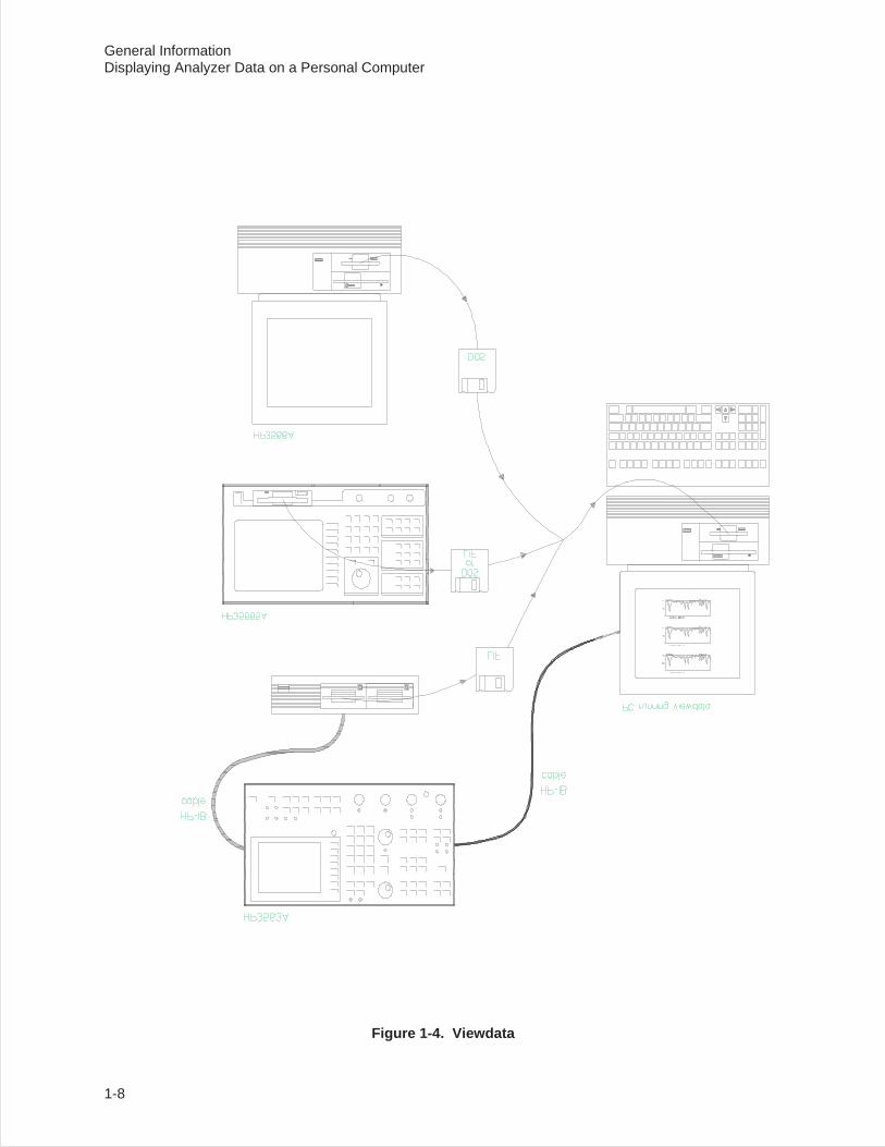
Figure 1-4. Viewdata
General InformationDisplaying Analyzer Data on a Personal Computer
1-8
Reading Data from Files into a Program
The functions in the SDF Libraries allow you to write your own C programs accessing SDF data viafunction calls. Chapter 6 describes libraries and includes a sample program.
Minimum Requirements
To run the utilities, you need the following:
• An IBM PC compatible and MS-DOS 2.1 (or greater). You can run the software from ahigh-density flexible disk drive or from your hard disk drive (a minimum of two drives arerequired).
• At least 256 kilobytes (K) of memory, 384K of memory is recommended.
General InformationReading Data from Files into a Program
1-9
Installation
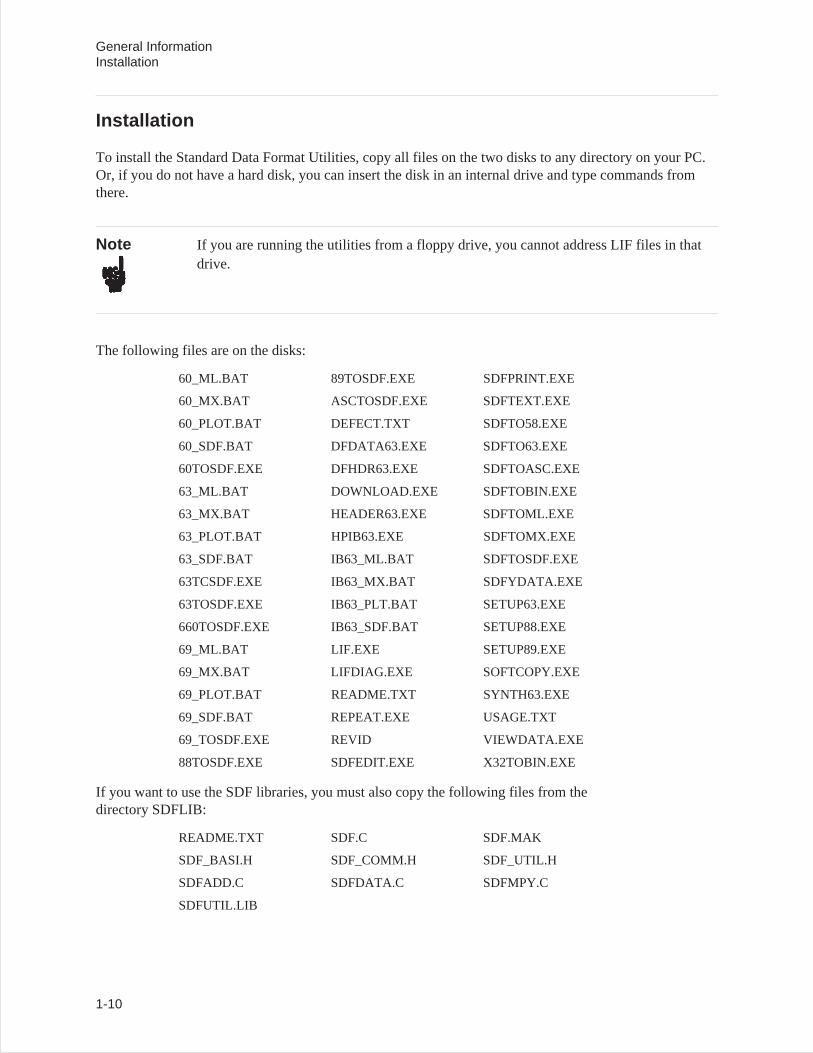
To install the Standard Data Format Utilities, copy all files on the two disks to any directory on your PC.Or, if you do not have a hard disk, you can insert the disk in an internal drive and type commands fromthere.
Note If you are running the utilities from a floppy drive, you cannot address LIF files in thatdrive.
The following files are on the disks:
60_ML.BAT 89TOSDF.EXE SDFPRINT.EXE
60_MX.BAT ASCTOSDF.EXE SDFTEXT.EXE
60_PLOT.BAT DEFECT.TXT SDFTO58.EXE
60_SDF.BAT DFDATA63.EXE SDFTO63.EXE
60TOSDF.EXE DFHDR63.EXE SDFTOASC.EXE
63_ML.BAT DOWNLOAD.EXE SDFTOBIN.EXE
63_MX.BAT HEADER63.EXE SDFTOML.EXE
63_PLOT.BAT HPIB63.EXE SDFTOMX.EXE
63_SDF.BAT IB63_ML.BAT SDFTOSDF.EXE
63TCSDF.EXE IB63_MX.BAT SDFYDATA.EXE
63TOSDF.EXE IB63_PLT.BAT SETUP63.EXE
660TOSDF.EXE IB63_SDF.BAT SETUP88.EXE
69_ML.BAT LIF.EXE SETUP89.EXE
69_MX.BAT LIFDIAG.EXE SOFTCOPY.EXE
69_PLOT.BAT README.TXT SYNTH63.EXE
69_SDF.BAT REPEAT.EXE USAGE.TXT
69_TOSDF.EXE REVID VIEWDATA.EXE
88TOSDF.EXE SDFEDIT.EXE X32TOBIN.EXE
If you want to use the SDF libraries, you must also copy the following files from thedirectory SDFLIB:
README.TXT SDF.C SDF.MAK
SDF_BASI.H SDF_COMM.H SDF_UTIL.H
SDFADD.C SDFDATA.C SDFMPY.C
SDFUTIL.LIB
General InformationInstallation
1-10

2
What is Standard Data Format?
Introduction
Standard Data Format, SDF, is a data format that allows measurement and analysis data to be sharedamong several HP analyzers (see chapter 1 for a list of the supported analyzers). See appendix B for acomplete description of each field in the SDF file.
SDF supports analyzers with a very broad range of functionality. Not all the supported analyzers useSDF’s full capabilities. The rest of this chapter describes some of these differences. Use the SDFTOSDFutility (described in chapter 4) to extract from an SDF file the information of interest.
2-1
Measurement (Data) Results
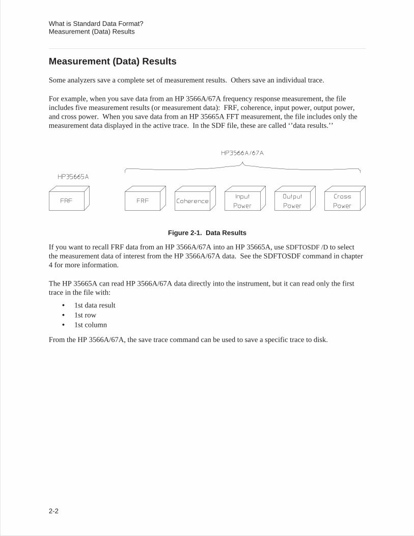
Some analyzers save a complete set of measurement results. Others save an individual trace.
For example, when you save data from an HP 3566A/67A frequency response measurement, the fileincludes five measurement results (or measurement data): FRF, coherence, input power, output power,and cross power. When you save data from an HP 35665A FFT measurement, the file includes only themeasurement data displayed in the active trace. In the SDF file, these are called ‘’data results.’’
Figure 2-1. Data Results
If you want to recall FRF data from an HP 3566A/67A into an HP 35665A, useSDFTOSDF /Dto selectthe measurement data of interest from the HP 3566A/67A data. See the SDFTOSDF command in chapter4 for more information.
The HP 35665A can read HP 3566A/67A data directly into the instrument, but it can read only the firsttrace in the file with:
• 1st data result• 1st row• 1st column
From the HP 3566A/67A, the save trace command can be used to save a specific trace to disk.
What is Standard Data Format?Measurement (Data) Results
2-2
Number of Input Channels (Rows)
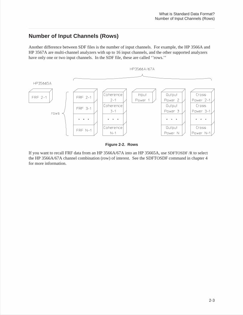
Another difference between SDF files is the number of input channels. For example, the HP 3566A andHP 3567A are multi-channel analyzers with up to 16 input channels, and the other supported analyzershave only one or two input channels. In the SDF file, these are called ‘’rows.’’
Figure 2-2. Rows
If you want to recall FRF data from an HP 3566A/67A into an HP 35665A, useSDFTOSDF /Rto selectthe HP 3566A/67A channel combination (row) of interest. See the SDFTOSDF command in chapter 4for more information.
What is Standard Data Format?Number of Input Channels (Rows)
2-3
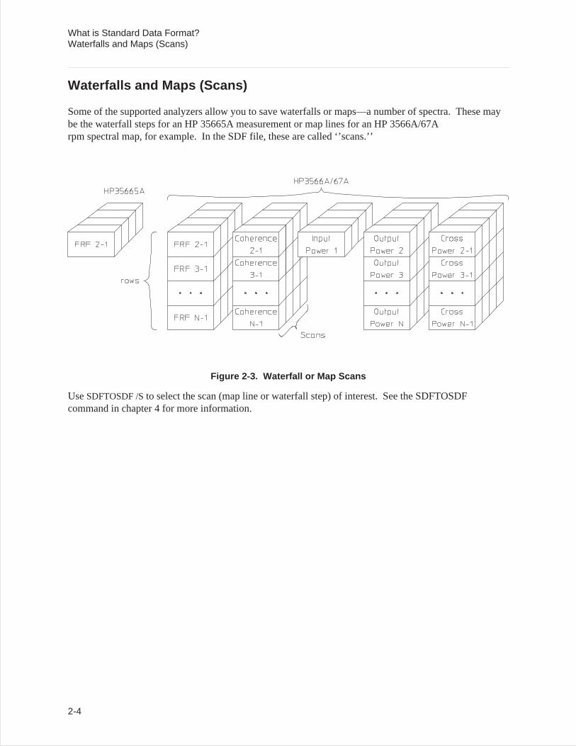
Waterfalls and Maps (Scans)
Some of the supported analyzers allow you to save waterfalls or maps—a number of spectra. These maybe the waterfall steps for an HP 35665A measurement or map lines for an HP 3566A/67Arpm spectral map, for example. In the SDF file, these are called ‘’scans.’’
Figure 2-3. Waterfall or Map Scans
UseSDFTOSDF /Sto select the scan (map line or waterfall step) of interest. See the SDFTOSDFcommand in chapter 4 for more information.
What is Standard Data Format?Waterfalls and Maps (Scans)
2-4
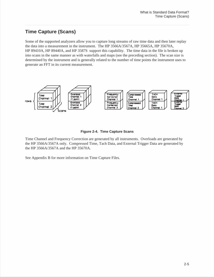
Time Capture (Scans)
Some of the supported analyzers allow you to capture long streams of raw time data and then later replaythe data into a measurement in the instrument. The HP 3566A/3567A, HP 35665A, HP 35670A,HP 89410A, HP 89440A, and HP 3587S support this capability. The time data in the file is broken upinto scans in the same manner as with waterfalls and maps (see the preceding section). The scan size isdetermined by the instrument and is generally related to the number of time points the instrument uses togenerate an FFT in its current measurement.
Figure 2-4. Time Capture Scans
Time Channel and Frequency Correction are generated by all instruments. Overloads are generated bythe HP 3566A/3567A only. Compressed Time, Tach Data, and External Trigger Data are generated bythe HP 3566A/3567A and the HP 35670A.
See Appendix B for more information on Time Capture Files.
What is Standard Data Format?Time Capture (Scans)
2-5

3
File System Conversion (LIF/DOS)
Description
LIF (Logical Interchange Format) is the Hewlett-Packard standard disk format that may be used toexchange files among various HP computer systems and instruments. The LIF programs in the StandardData Format Utilities make it possible for personal computer users to translate LIF files into DOS fileformat, and DOS files into LIF format. The utilities support file conversion for both internal drives andexternal drives (connected on the HP-IB). These utilities can also format and initialize LIF disks onexternal HP drives.
The LIF utilities consist of the following commands:
LIF Main program for LIF access. The first parameter specifies the function (e.g.,SCAN or CHK). Each function has its own options. These options are documentedlater in this chapter.
LIF SCAN Checks the PC for internal floppy drives and for HP-IB interface boards and thenlooks for disk drives (capable of reading LIF disks) connected to HP-IB.
LIF CHK Verifies that the disk inserted in a designated drive is fully readable by the LIFUtilities. (To abort, type:CTRL-C.)
LIF LS Lists the contents of the LIF directory.
LIF CP Copies a LIF file to a DOS file, a DOS file to a LIF file, or a LIF file to another LIFfile.
LIF RM Deletes a specified file from the LIF directory.
LIF INIT Optionally formats and initializes a new directory on a LIF disk. (To abort,type:CTRL-C.)
LIFDIAG Diagnostic utility useful for performing fast LIF to LIF full disk backups and forrecovering data from damaged/corrupted disks.
3-1
Hardware and Software Requirements
Use of these utilities requires an IBM PC compatible with the MS-DOS 2.1 operating system (or greater).If you wish to translate or format LIF files located on an external drive you must have an SS/80 driveconnected to your PC with an HP-IB card. The LIF utilities recognize all HP SS/80 drives including theHP 9122, HP 9133 (D,H,L), HP 9127A and HP 9153A. Older disk drives (AMIGO command set) suchas the HP 9121, HP 9133 (V, X, or XV) will not work. (SS/80 disks are a subset of HP CS/80 disks.)There are no requirements for internal disk drives.
The HP 88500A and HP 82335 HP-IB cards, as well as the National GPIB PCII and AT-GPIB cards arerecognized. Make sure that your HP-IB (or GPIB) is set to System Controller, the default switch setting.
Caution Disk cache programs may interfere with the LIF utilities access to theinternal floppy disk drives and may cause disk read errors or program lockup.We recommend that disk cache programs not be used in conjunction withthese utilities.
You can use the SMARTDrive disk caching software provided with Microsoft Windows3.0.
Note The utilities will work with both an HP and a National card installed simultaneously.For example, you can LIF copy files from a disk drive on the HP card to a disk drive onthe National Instrument card.
Both BDAT and ASCII LIF files may be converted to DOS. (Binary LIF files are copied inraw mode.)
Note When using these utilities, remember the following:• The LIF utilities do not format internal disks (only external).• It’s not possible to initialize a LIF directory onto an unformatted disk.
File System Conversion (LIF/DOS)Hardware and Software Requirements
3-2
Online Help
Online Help is available for each LIF utility command. For a description of a particular command and alist of its options, simply type the command name and/U. Then press return.
For example, to get help on the command LIF CHK, type:
LIF CHK /U [ Enter ]
File System Conversion (LIF/DOS)Online Help
3-3
LIF
Main program for LIF access. The first parameter specifies operation. Each operation has its own set offiles/options. For more help on a particular command, see the rest of this chapter.
Syntax
LIF <operation> [files] [options]
Operations
SCAN look for LIF disk drives (external or internal)
CHK or CHECK check disk integrity (read all tracks/heads)
LS or DIR list files on LIF disk
CP or COPY copy file(s) between DOS and LIF disks
RM or DEL remove a LIF file
INIT initialize (format) a LIF disk
The specified <operation> has its own set of files/options. For more help on a particular command, type‘’lif’’ followed by the operation name (except for SCAN) and /U. For example, for help on the LIF CPcommand, type:LIF CP /U
File System Conversion (LIF/DOS)LIF
3-4
LIF SCAN
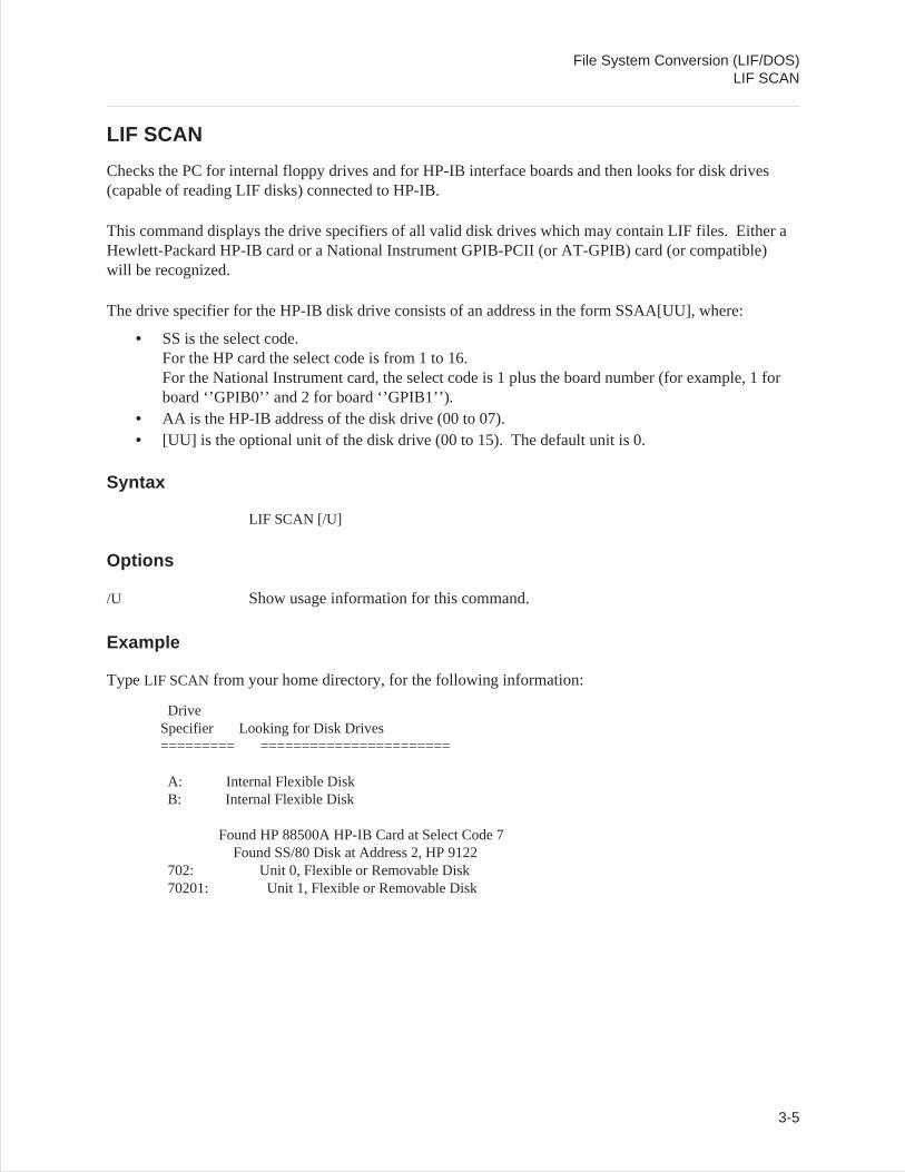
Checks the PC for internal floppy drives and for HP-IB interface boards and then looks for disk drives(capable of reading LIF disks) connected to HP-IB.
This command displays the drive specifiers of all valid disk drives which may contain LIF files. Either aHewlett-Packard HP-IB card or a National Instrument GPIB-PCII (or AT-GPIB) card (or compatible)will be recognized.
The drive specifier for the HP-IB disk drive consists of an address in the form SSAA[UU], where:
• SS is the select code.For the HP card the select code is from 1 to 16.For the National Instrument card, the select code is 1 plus the board number (for example, 1 forboard ‘’GPIB0’’ and 2 for board ‘’GPIB1’’).
• AA is the HP-IB address of the disk drive (00 to 07).• [UU] is the optional unit of the disk drive (00 to 15). The default unit is 0.
Syntax
LIF SCAN [/U]
Options
/U Show usage information for this command.
Example
TypeLIF SCAN from your home directory, for the following information:
DriveSpecifier Looking for Disk Drives========= =======================
A: Internal Flexible DiskB: Internal Flexible Disk
Found HP 88500A HP-IB Card at Select Code 7Found SS/80 Disk at Address 2, HP 9122
702: Unit 0, Flexible or Removable Disk70201: Unit 1, Flexible or Removable Disk
File System Conversion (LIF/DOS)LIF SCAN
3-5
Discussion
‘’702:’’ identifies a disk drive at address 2 and unit 0 connected to an HP card at select code 7. If both anHP card and an National Instrument card are connected to the same select code, then only the HP cardwill be recognized. This is usually not a problem since the customary select code of the HP card is 7, andthe customary board name for the National Instrument card is ‘’GPIB0’’ (select code 1). The LIFprograms are capable of working with both boards installed simultaneously (e.g., LIF copy from a diskdrive on the HP card to a disk drive on the National Instrument card).
LIF SCAN indicates how to address a LIF disk in an external drive, not a DOS disk. If a DOS disk is inyour external drive, you cannot access it as ‘’702:’’ or ‘’70201:’’. Instead, use the letter drive code thatDOS has assigned (e.g., E: or F:).
MS-DOS requires that an external drive be powered up and connected at power-on to be recognized as anMS-DOS drive. The LIF program do not require external drives to be on at power-on to be accessible asa LIF drive.
File System Conversion (LIF/DOS)LIF SCAN
3-6
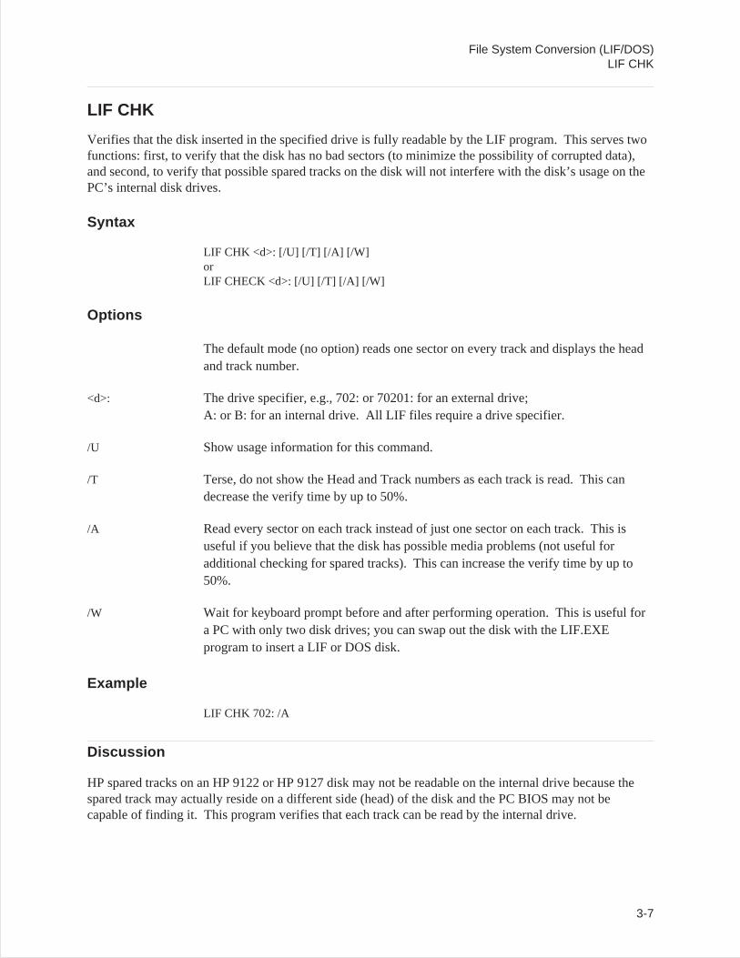
LIF CHK
Verifies that the disk inserted in the specified drive is fully readable by the LIF program. This serves twofunctions: first, to verify that the disk has no bad sectors (to minimize the possibility of corrupted data),and second, to verify that possible spared tracks on the disk will not interfere with the disk’s usage on thePC’s internal disk drives.
Syntax
LIF CHK <d>: [/U] [/T] [/A] [/W]orLIF CHECK <d>: [/U] [/T] [/A] [/W]
Options
The default mode (no option) reads one sector on every track and displays the headand track number.
<d>: The drive specifier, e.g., 702: or 70201: for an external drive;A: or B: for an internal drive. All LIF files require a drive specifier.
/U Show usage information for this command.
/T Terse, do not show the Head and Track numbers as each track is read. This candecrease the verify time by up to 50%.
/A Read every sector on each track instead of just one sector on each track. This isuseful if you believe that the disk has possible media problems (not useful foradditional checking for spared tracks). This can increase the verify time by up to50%.
/W Wait for keyboard prompt before and after performing operation. This is useful fora PC with only two disk drives; you can swap out the disk with the LIF.EXEprogram to insert a LIF or DOS disk.
Example
LIF CHK 702: /A
Discussion
HP spared tracks on an HP 9122 or HP 9127 disk may not be readable on the internal drive because thespared track may actually reside on a different side (head) of the disk and the PC BIOS may not becapable of finding it. This program verifies that each track can be read by the internal drive.
File System Conversion (LIF/DOS)LIF CHK
3-7
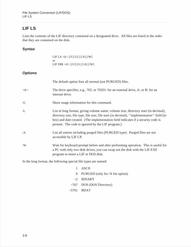
LIF LS
Lists the contents of the LIF directory contained on a designated drive. All files are listed in the orderthat they are contained on the disk.
Syntax
LIF LS <d>: [/U] [/L] [/A] [/W]orLIF DIR <d>: [/U] [/L] [/A] [/W]
Options
The default option lists all normal (not PURGED) files.
<d>: The drive specifier, e.g., 702: or 70201: for an external drive, A: or B: for aninternal drive.
/U Show usage information for this command.
/L List in long format, giving volume name, volume size, directory start (in decimal),directory size, file type, file size, file start (in decimal), ‘’implementation’’ field (inhex) and date created. (The implementation field indicates if a security code ispresent. The code is ignored by the LIF program.)
/A List all entries including purged files (PURGED type). Purged files are notaccessible by LIF CP.
/W Wait for keyboard prompt before and after performing operation. This is useful fora PC with only two disk drives; you can swap out the disk with the LIF.EXEprogram to insert a LIF or DOS disk.
In the long format, the following special file types are named:
1 ASCII
0 PURGED (only for /A list option)
−2 BINARY
−767 DOS (DOS Directory)
−5791 BDAT
File System Conversion (LIF/DOS)LIF LS
3-8
Example
List directory in long format:
LIF LS 702: /L
Route directory listing to a file in your home directory:
LIF LS 702: /A > FILELIST
Discussion
HP 3563A (or HP 3562A) files are all of type BDAT and the first two letters of the file name specifies thefile type as follows:
A1-A5 Aseq1 through Aseq5
AM Amath
CF Cv Fit (S domain CurveFit)
CS Capture
DA Data
DM Demod (Delete Frequency)
FL Fault (Fault Log)
SE State
ST Synth (S domain)
TS Thrupt
TL Test (Test Log)
ZF Z CvFt (Z domain CurveFit)
ZT Z Snth (Z domain Synth)
PI Pictur (Display graphics)
File System Conversion (LIF/DOS)LIF LS
3-9
LIF CP
Copies a LIF file to a DOS file, a DOS file to a LIF file, or a LIF file to another LIF file. <sfile> is thesource file name and <dfile> is the destination file name. The full path name must be specified for a LIFfile. LIF ASCII and BDAT formats are automatically converted to DOS format. All other files arecopied with no conversion. At least one of the files must be in a LIF directory (source or destination file).This may be one of the internal flexible disk drives (e.g., A: or B:) or it may be an external HP-IB diskdrive (e.g., 700: or 70001:).
Syntax
LIF CP <sfile> <dfile> [/U] [/O] [/B] [/A] [/R][/T:<fileType>] [/I:<implement>] [/N] [/S:<lineSize>] [/W]orLIF COPY <sfile> <dfile> [/U] [/O] [/B] [/A] [/R][/T:<fileType] [/I:<implement>] [/N] [/S:<lineSize>] [/W]
Options
<sfile> Source path and file name (must include drive specifier if file is LIF ). May containwild card characters ‘’*’’ and ‘’?’’.
<dfile> Destination path and file name (must include drive specifier if file is LIF ). Maycontain wild card characters ‘’*’’ and ‘’?’’.
/U Show usage information for this command.
/B BDAT file copy (use only for DOS to LIF ).
/A ASCII file copy (use for DOS to LIF ).
/R Raw file copy (DOS to LIF or LIF to DOS). Do not convert file (copy as is).
/T:<fileType> (LIF destination only) Set the file type for the destination file to the specified filetype. This may be specified in decimal or hexadecimal (prefix with ‘’0x’’). Thefile type specified will not affect any possible file conversions.
/I:<implement> Set the implementation field for the destination LIF file (DOS to LIF or LIF toLIF ). This may be specified in decimal or hexadecimal (prefix with ‘’0x’’).
/N Do not translate to valid LIF file name.
/S:<lineSize> Maximum line size for DOS to LIF ASCII file transfer (default 256 characters).
/W Wait for keyboard prompt before and after performing operation. This is useful fora PC with only two disk drives; you can swap out the disk with the LIF.EXEprogram to insert a LIF or DOS disk.
File System Conversion (LIF/DOS)LIF CP
3-10
Example
LIF to DOS copy from an external drive to your current PC directory:
LIF CP 702:DAFREQ DSK_FREQ
DOS to LIF copy from home directory to external drive. /N option is used to allow the LIF file name tobegin with a number. If /N were not typed the file name would be X77PSD.
Note Invalid LIF filenames may cause files to be inaccessible by another LIF system, e.g.,Pascal workstations or HP BASIC.
LIF CP 77PSD 702:77PSD /N
DOS to LIF copy from DOS external drive to LIF external drive:
LIF CP 702:DAFREQ E:FREQ
DOS to LIF copy forcing long line length:
LIF CP LONG.ASC 702:LONGLINES /S:1000
Discussion
Any specified LIF file name is automatically translated to contain a valid LIF file name as follows:
• Shifts lower to upper case.• Allows ‘’_’’, ‘’.’’, and digits (0-9).• Translates all other characters to the letter ‘’X’’.• If the first character is not a letter, then the file name will be preceded by the letter ‘’X’’.• Truncates file names to 10 characters.
Only two types of file conversions (i.e., not raw copy) are allowed between LIF and DOS files: ASCIIand BDAT. LIF Binary files are not converted.
For a LIF to DOS file copy, LIF ASCII files are converted to DOS ASCII files and LIF BDAT files areconverted to DOS Binary files. All other files are copied in raw mode (exactly as they appear in theLIF file). The automatic conversions for LIF ASCII and BDAT files may be turned off with the rawoption (/R).
File System Conversion (LIF/DOS)LIF CP
3-11
If a directory is specified as a destination, then a file with the same name as the source file will be created.If only a directory is specified as a source, then all files in the directory will be copied. For a DOS toLIF file copy, the file will be converted to either ASCII or BDAT automatically if no format conversion isspecified (/A, /B, or /R).
If the first 80 characters of the DOS file contain only printable ASCII characters (or tab, carriage return,or line feed), then the file will be converted to LIF ASCII, otherwise it will be converted to LIF BDAT.The file may be forced to be converted to LIF ASCII with the ASCII option (/A). A file may be forced tobe converted to BDAT format by specifying the BDAT option (/B) and a raw copy (no conversions) canbe specified with the raw option (/R).
DOS file LIF file
BINARY (no option) becomes BDAT
ASCII (no option) becomes ASCII
BINARY (with /Aoption)
becomes ASCII
ASCII (with /B option) becomes BDAT
LIF file DOS file
BDAT becomes BINARY
ASCII becomes ASCII
Caution If the input file is ASCII for a DOS to LIF copy, the input lines will be truncated to thevalue set by /S option (default is 256 characters). If truncations occurs, the followingmessage will appear:
Line “X” truncates from “m” to “n” characters.
where ‘’X’’ is the line that was truncated, ‘’m’’ is the original line length, and ‘’n’’ isthe truncated line length.
Use the /S option to increase the maximum input line length. Note that the /S option does not need to bespecified for LIF to LIF or LIF to DOS file copies.
For a LIF to LIF copy, all files are copied as is (no conversion) with the destination file created with thesame file type as the source file.
Multiple files may be copied if the source file specification is a directory or the wildcards ‘’*’’ (match 0or more of any character) or ‘’?’’ (match 1 occurrence of any character) are used. In this case, thedestination file specification should also be a directory or contain matching wildcards. Each file will becopied to this directory. If the destination is not a directory and doesn’t contain wildcards, then all fileswill be copied to the same destination file (not appended). This is only useful to copy files to your screenor to a printer, as LIF CP will not write to an existing file (except CON or PRN devices).
File System Conversion (LIF/DOS)LIF CP
3-12

File System Conversion (LIF/DOS)LIF CP
3-13
Example 1
Copy all the DOS files in the directory \DOSdir to the LIF disk at 702:
LIF CP a:\DOSdir 702:
Example 2
Copy all the DOS files with the suffix ‘’.doc’’ to LIF disk at 702:
LIF CP *.doc 702:
Example 3
Copy all HP 3562A data files (prefix ‘’DA’’) from a LIF disk at 702: to the current DOS directory,changing the ‘’DA’’ prefix to a ‘’.63’’ suffix.
LIF CP 702:DA* *.63
File System Conversion (LIF/DOS)LIF CP
3-14
LIF RM
Removes (deletes) the specified file from the LIF directory.
Syntax
LIF RM <file> [/U] [/N] [/F] [/W]orLIF DEL <file> [/U] [/N] [/F] [/W]
Options
<file> File name. Must include drive specifier (702:, A:, etc.).
/U Show usage information for this command.
/N Do not translate to valid LIF file name.
/F Force remove (i.e., external DOS directory).
/W Wait for keyboard prompt before and after performing operation. This is useful fora PC with only two disk drives; you can swap out the disk with the LIF.EXEprogram to insert a LIF or DOS disk.
Example
Look for a file called 00DATA. If it doesn’t exist, it won’t remove any files.
LIF RM 702:00data
Remove a file with the name ‘’00data’’.
LIF RM 702:00data /N
File System Conversion (LIF/DOS)LIF RM
3-15
Discussion
When you type in the name of a file (except where /N is specified), this utility automatically converts avalid LIF file name as follows:
• Shifts lower to upper case.• Allows ‘’_’’, ‘’.’’, and digits (0-9).• Translates all other characters to the letter ‘’X’’.• If the first character is not a letter, then the file name will be preceded by the letter ‘’X’’.• Truncates file names to 10 characters.
Caution Be careful with this command; a DOS directory on an external HP-IB disk drive (forexample, an HP 9133D) is actually a LIF directory with one entry (for example,VOLUME000) and can be removed with this utility only by specifying the /F option.
File System Conversion (LIF/DOS)LIF RM
3-16
LIF INIT
The command LIF INIT optionally formats and initializes a new directory on a LIF disk.
Syntax
LIF INIT <d>:[name] [/U] [/F] [/O:<opt>] [/I:<intrlv>] [/W]
Options
<d>: Drive specifier (702:, A:).
[name] Optional new LIF directory name (up to 6 characters).
/U Show usage information for this command.
/F Format disk before initializing directory. This operation may take a few minutes tocomplete. This operation may not be necessary if the disk is already formatted.Disks can only be formatted on external HP-IB disk drives.
/O:<opt> Format option. This integer number specifies the disk sector size and other diskdrive dependent information. Refer to your disk drive owner’s manual for possiblevalues and their specific meaning. (If you have an HP 9122 or HP 9127, see theformatting options on the following pages.) If not specified, then a format option of0 is used. The format option is only used if format disk (/F) is specified.
/I:<intrlv> Sector interleave factor. A value of 1 is the default. The interleave factor is onlyused if format disk (/F) is specified.
/W Wait for keyboard prompt before and after performing operation. This is useful fora PC with only two disk drives; you can swap out the disk with the LIF.EXEprogram to insert a LIF or DOS disk.
Caution Do not eject disk while formatting.
File System Conversion (LIF/DOS)LIF INIT
3-17
Example
Format a disk in an external drive:
LIF INIT 702:MIKE /F
Format a single-sided disk on an HP 9122D:
LIF INIT 702:HALL /F /O:4 /I:2
Discussion
The [name] specified (in this case ‘’HALL’’) is the new LIF directory’s volume name and isautomatically translated to contain a valid LIF volume name as follows:
• Shifts lower to upper case.• Allows ‘’_’’, ‘’.’’, and digits (0-9).• Translates all other characters to the letter ‘’X’’.• If the first character is not a letter, then the volume name will be preceded by the letter ‘’X’’.• LIF INIT truncates file names to 6 characters. If no name is specified, then the LIF volume name
will be blank.
Disks can only be formatted on external HP-IB disk drives (i.e., not on internal flexible disk drives).
Note Any LIF disk used with the HP 3563A/62A must have a non-empty LIF Volume name.This means that if you are formatting a disk on the PC with LIF INIT, always specifythe ‘’Optional new LIF directory name.’’
File System Conversion (LIF/DOS)LIF INIT
3-18
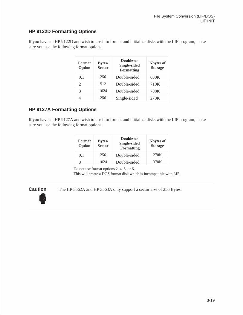
HP 9122D Formatting Options
If you have an HP 9122D and wish to use it to format and initialize disks with the LIF program, makesure you use the following format options.
FormatOption
Bytes/Sector
Double-orSingle-sidedFormatting
Kbytes ofStorage
0,1 256 Double-sided 630K
2 512 Double-sided 710K
3 1024 Double-sided 788K
4 256 Single-sided 270K
HP 9127A Formatting Options
If you have an HP 9127A and wish to use it to format and initialize disks with the LIF program, makesure you use the following format options.
FormatOption
Bytes/Sector
Double-orSingle-sidedFormatting
Kbytes ofStorage
0,1 256 Double-sided 270K
3 1024 Double-sided 378K
Do not use format options 2, 4, 5, or 6.This will create a DOS format disk which is incompatible with LIF.
Caution The HP 3562A and HP 3563A only support a sector size of 256 Bytes.
File System Conversion (LIF/DOS)LIF INIT
3-19
LIFDIAG
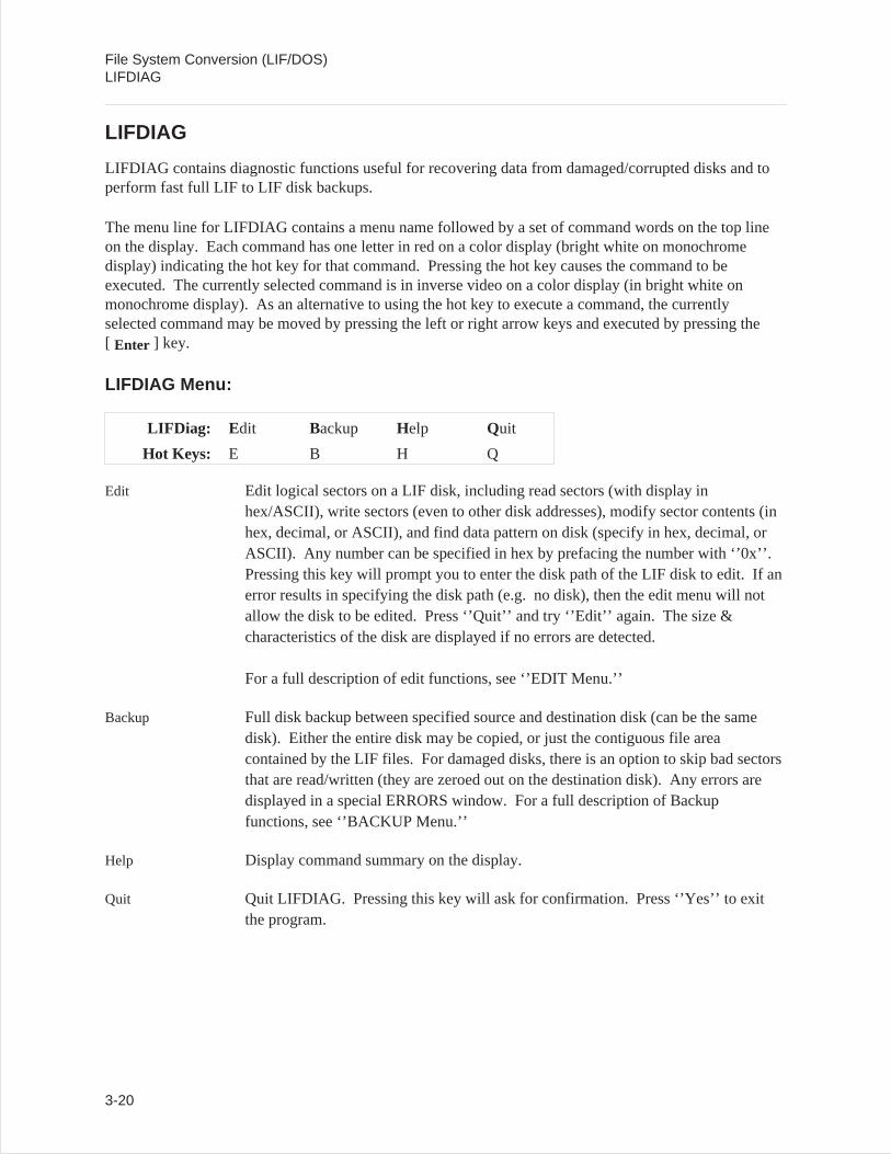
LIFDIAG contains diagnostic functions useful for recovering data from damaged/corrupted disks and toperform fast full LIF to LIF disk backups.
The menu line for LIFDIAG contains a menu name followed by a set of command words on the top lineon the display. Each command has one letter in red on a color display (bright white on monochromedisplay) indicating the hot key for that command. Pressing the hot key causes the command to beexecuted. The currently selected command is in inverse video on a color display (in bright white onmonochrome display). As an alternative to using the hot key to execute a command, the currentlyselected command may be moved by pressing the left or right arrow keys and executed by pressing the[ Enter ] key.
LIFDIAG Menu:
LIFDiag: E dit Backup Help Quit
Hot Keys: E B H Q
Edit Edit logical sectors on a LIF disk, including read sectors (with display inhex/ASCII), write sectors (even to other disk addresses), modify sector contents (inhex, decimal, or ASCII), and find data pattern on disk (specify in hex, decimal, orASCII). Any number can be specified in hex by prefacing the number with ‘’0x’’.Pressing this key will prompt you to enter the disk path of the LIF disk to edit. If anerror results in specifying the disk path (e.g. no disk), then the edit menu will notallow the disk to be edited. Press ‘’Quit’’ and try ‘’Edit’’ again. The size &characteristics of the disk are displayed if no errors are detected.
For a full description of edit functions, see ‘’EDIT Menu.’’
Backup Full disk backup between specified source and destination disk (can be the samedisk). Either the entire disk may be copied, or just the contiguous file areacontained by the LIF files. For damaged disks, there is an option to skip bad sectorsthat are read/written (they are zeroed out on the destination disk). Any errors aredisplayed in a special ERRORS window. For a full description of Backupfunctions, see ‘’BACKUP Menu.’’
Help Display command summary on the display.
Quit Quit LIFDIAG. Pressing this key will ask for confirmation. Press ‘’Yes’’ to exitthe program.
File System Conversion (LIF/DOS)LIFDIAG
3-20
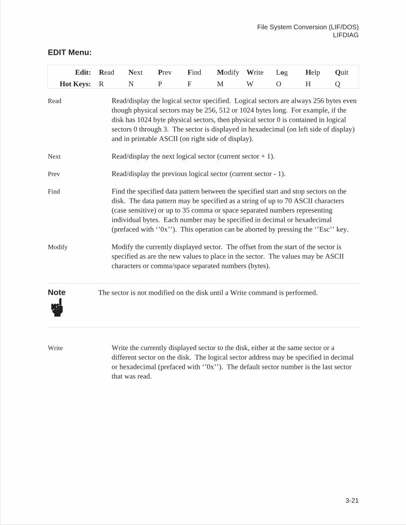
EDIT Menu:
Edit: R ead Next Prev Find Modify Write Log Help Quit
Hot Keys: R N P F M W O H Q
Read Read/display the logical sector specified. Logical sectors are always 256 bytes eventhough physical sectors may be 256, 512 or 1024 bytes long. For example, if thedisk has 1024 byte physical sectors, then physical sector 0 is contained in logicalsectors 0 through 3. The sector is displayed in hexadecimal (on left side of display)and in printable ASCII (on right side of display).
Next Read/display the next logical sector (current sector + 1).
Prev Read/display the previous logical sector (current sector - 1).
Find Find the specified data pattern between the specified start and stop sectors on thedisk. The data pattern may be specified as a string of up to 70 ASCII characters(case sensitive) or up to 35 comma or space separated numbers representingindividual bytes. Each number may be specified in decimal or hexadecimal(prefaced with ‘’0x’’). This operation can be aborted by pressing the ‘’Esc’’ key.
Modify Modify the currently displayed sector. The offset from the start of the sector isspecified as are the new values to place in the sector. The values may be ASCIIcharacters or comma/space separated numbers (bytes).
Note The sector is not modified on the disk until a Write command is performed.
Write Write the currently displayed sector to the disk, either at the same sector or adifferent sector on the disk. The logical sector address may be specified in decimalor hexadecimal (prefaced with ‘’0x’’). The default sector number is the last sectorthat was read.
File System Conversion (LIF/DOS)LIFDIAG
3-21
Log Specifies a log file where the displayed hex/ASCII sector contents will be appendedto. For example, ‘’prn’’ specifies the printer.
Help Display command summary on the display.
Quit Quit editing this disk.
Caution Always select ‘’Quit’’ and ‘’Edit’’ again before editing a new disk. Thesize & characteristics of the disk are only determined when the disk is initially edited.
File System Conversion (LIF/DOS)LIFDIAG
3-22
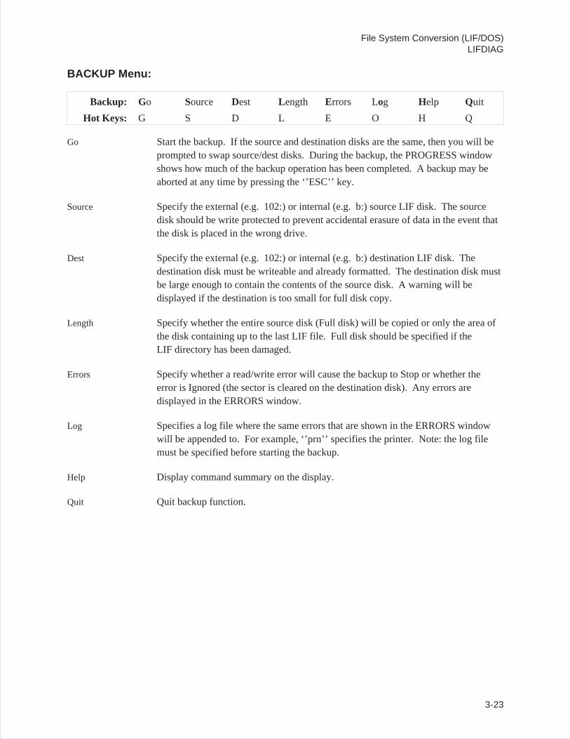
BACKUP Menu:
Backup: Go Source Dest Length Errors Log Help Quit
Hot Keys: G S D L E O H Q
Go Start the backup. If the source and destination disks are the same, then you will beprompted to swap source/dest disks. During the backup, the PROGRESS windowshows how much of the backup operation has been completed. A backup may beaborted at any time by pressing the ‘’ESC’’ key.
Source Specify the external (e.g. 102:) or internal (e.g. b:) source LIF disk. The sourcedisk should be write protected to prevent accidental erasure of data in the event thatthe disk is placed in the wrong drive.
Dest Specify the external (e.g. 102:) or internal (e.g. b:) destination LIF disk. Thedestination disk must be writeable and already formatted. The destination disk mustbe large enough to contain the contents of the source disk. A warning will bedisplayed if the destination is too small for full disk copy.
Length Specify whether the entire source disk (Full disk) will be copied or only the area ofthe disk containing up to the last LIF file. Full disk should be specified if theLIF directory has been damaged.
Errors Specify whether a read/write error will cause the backup to Stop or whether theerror is Ignored (the sector is cleared on the destination disk). Any errors aredisplayed in the ERRORS window.
Log Specifies a log file where the same errors that are shown in the ERRORS windowwill be appended to. For example, ‘’prn’’ specifies the printer. Note: the log filemust be specified before starting the backup.
Help Display command summary on the display.
Quit Quit backup function.
File System Conversion (LIF/DOS)LIFDIAG
3-23
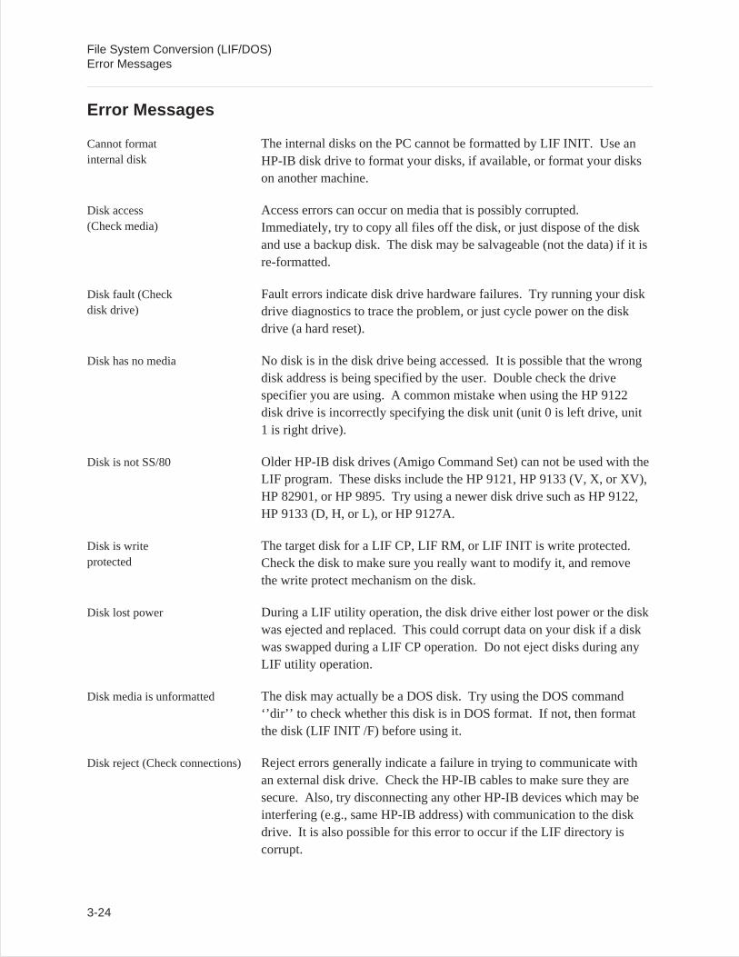
Error Messages
Cannot formatinternal disk
The internal disks on the PC cannot be formatted by LIF INIT. Use anHP-IB disk drive to format your disks, if available, or format your diskson another machine.
Disk access(Check media)
Access errors can occur on media that is possibly corrupted.Immediately, try to copy all files off the disk, or just dispose of the diskand use a backup disk. The disk may be salvageable (not the data) if it isre-formatted.
Disk fault (Checkdisk drive)
Fault errors indicate disk drive hardware failures. Try running your diskdrive diagnostics to trace the problem, or just cycle power on the diskdrive (a hard reset).
Disk has no media No disk is in the disk drive being accessed. It is possible that the wrongdisk address is being specified by the user. Double check the drivespecifier you are using. A common mistake when using the HP 9122disk drive is incorrectly specifying the disk unit (unit 0 is left drive, unit1 is right drive).
Disk is not SS/80 Older HP-IB disk drives (Amigo Command Set) can not be used with theLIF program. These disks include the HP 9121, HP 9133 (V, X, or XV),HP 82901, or HP 9895. Try using a newer disk drive such as HP 9122,HP 9133 (D, H, or L), or HP 9127A.
Disk is writeprotected
The target disk for a LIF CP, LIF RM, or LIF INIT is write protected.Check the disk to make sure you really want to modify it, and removethe write protect mechanism on the disk.
Disk lost power During a LIF utility operation, the disk drive either lost power or the diskwas ejected and replaced. This could corrupt data on your disk if a diskwas swapped during a LIF CP operation. Do not eject disks during anyLIF utility operation.
Disk media is unformatted The disk may actually be a DOS disk. Try using the DOS command‘’dir’’ to check whether this disk is in DOS format. If not, then formatthe disk (LIF INIT /F) before using it.
Disk reject (Check connections) Reject errors generally indicate a failure in trying to communicate withan external disk drive. Check the HP-IB cables to make sure they aresecure. Also, try disconnecting any other HP-IB devices which may beinterfering (e.g., same HP-IB address) with communication to the diskdrive. It is also possible for this error to occur if the LIF directory iscorrupt.
File System Conversion (LIF/DOS)Error Messages
3-24
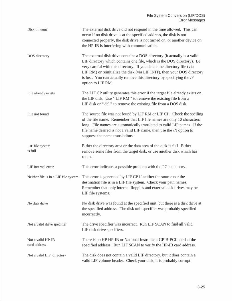
Disk timeout The external disk drive did not respond in the time allowed. This canoccur if no disk drive is at the specified address, the disk is notconnected properly, the disk drive is not turned on, or another device onthe HP-IB is interfering with communication.
DOS directory The external disk drive contains a DOS directory (it actually is a validLIF directory which contains one file, which is the DOS directory). Bevery careful with this directory. If you delete the directory file (viaLIF RM) or reinitialize the disk (via LIF INIT), then your DOS directoryis lost. You can actually remove this directory by specifying the /Foption to LIF RM.
File already exists The LIF CP utility generates this error if the target file already exists onthe LIF disk. Use ‘’LIF RM’’ to remove the existing file from aLIF disk or ‘’del’’ to remove the existing file from a DOS disk.
File not found The source file was not found by LIF RM or LIF CP. Check the spellingof the file name. Remember that LIF file names are only 10 characterslong. File names are automatically translated to valid LIF names. If thefile name desired is not a valid LIF name, then use the /N option tosuppress the name translations.
LIF file systemis full
Either the directory area or the data area of the disk is full. Eitherremove some files from the target disk, or use another disk which hasroom.
LIF internal error This error indicates a possible problem with the PC’s memory.
Neither file is in a LIF file system This error is generated by LIF CP if neither the source nor thedestination file is in a LIF file system. Check your path names.Remember that only internal floppies and external disk drives may beLIF file systems.
No disk drive No disk drive was found at the specified unit, but there is a disk drive atthe specified address. The disk unit specifier was probably specifiedincorrectly.
Not a valid drive specifier The drive specifier was incorrect. Run LIF SCAN to find all validLIF disk drive specifiers.
Not a valid HP-IBcard address
There is no HP HP-IB or National Instrument GPIB-PCII card at thespecified address. Run LIF SCAN to verify the HP-IB card address.
Not a valid LIF directory The disk does not contain a valid LIF directory, but it does contain avalid LIF volume header. Check your disk, it is probably corrupt.
File System Conversion (LIF/DOS)Error Messages
3-25
Not a valid LIFfile system
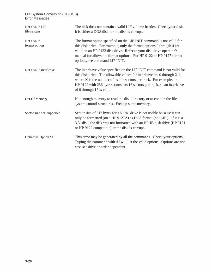
The disk does not contain a valid LIF volume header. Check your disk,it is either a DOS disk, or the disk is corrupt.
Not a validformat option
The format option specified on the LIF INIT command is not valid forthis disk drive. For example, only the format options 0 through 4 arevalid on an HP 9122 disk drive. Refer to your disk drive operator’smanual for allowable format options. For HP 9122 or HP 9127 formatoptions, see command LIF INIT.
Not a valid interleave The interleave value specified on the LIF INIT command is not valid forthis disk drive. The allowable values for interleave are 0 through X-1where X is the number of usable sectors per track. For example, anHP 9122 with 256 byte sectors has 16 sectors per track, so an interleaveof 0 through 15 is valid.
Out Of Memory Not enough memory to read the disk directory or to contain the filesystem control structures. Free up some memory.
Sector size not supported Sector size of 512 bytes for a 5 1/4" drive is not usable because it canonly be formatted (on a HP 9127A) as DOS format (not LIF ). If it is a3.5" disk, the disk was not formatted with an HP-IB disk drive (HP 9121or HP 9122 compatible) or the disk is corrupt.
Unknown Option ‘X’ This error may be generated by all the commands. Check your options.Typing the command with /U will list the valid options. Options are notcase sensitive or order dependant.
File System Conversion (LIF/DOS)Error Messages
3-26
4
Sharing Data Between Analyzers
Introduction
The Standard Data Format Utilities are programs that translate data files from the HP 35665A,HP 3560A, HP 3563A, HP 3562A, HP 3566A, HP 3567A, HP 3588A, or HP 3589A analyzers toStandard Data Format or formats compatible with ASCII, Data Set 58, PC-MATLAB, and MATRIXx.
Conversions from Standard Data Format to STARModal and STARAcoustics formats are available fromStructural Measurement Systems.
With the Standard Data Format utilities you can share data between the supported HP DSA analyzersusing these general steps:
1. Make a measurement with one of the supported HP DSA analyzers.
2. Save the measurement data.
3. Convert the data using the appropriate conversion utility.
4. Recall the data into another analyzer.
5. Do further analysis on the data, or compare it to other data.
For example, you can make a frequency response measurement with an HP 3560A, transfer thedata to your PC, convert it to SDF format, then recall it into an HP 35665A for curve fitting(see figure 1-2).
Or you can compare old data from an HP 3562A to new data from an HP 35665A (see figure 1-3).
PC-MATLAB (a trademark of The MathWorks, Inc.) and MATRIXx (a product of Integrated SystemsInc.) are PC-based software packages for scientific and engineering numeric computation. HP SDF datafiles may be ported to either of these packages using the Conversion Utilities. See appendix A forexamples of how to load SDF data into these application packages.
4-1
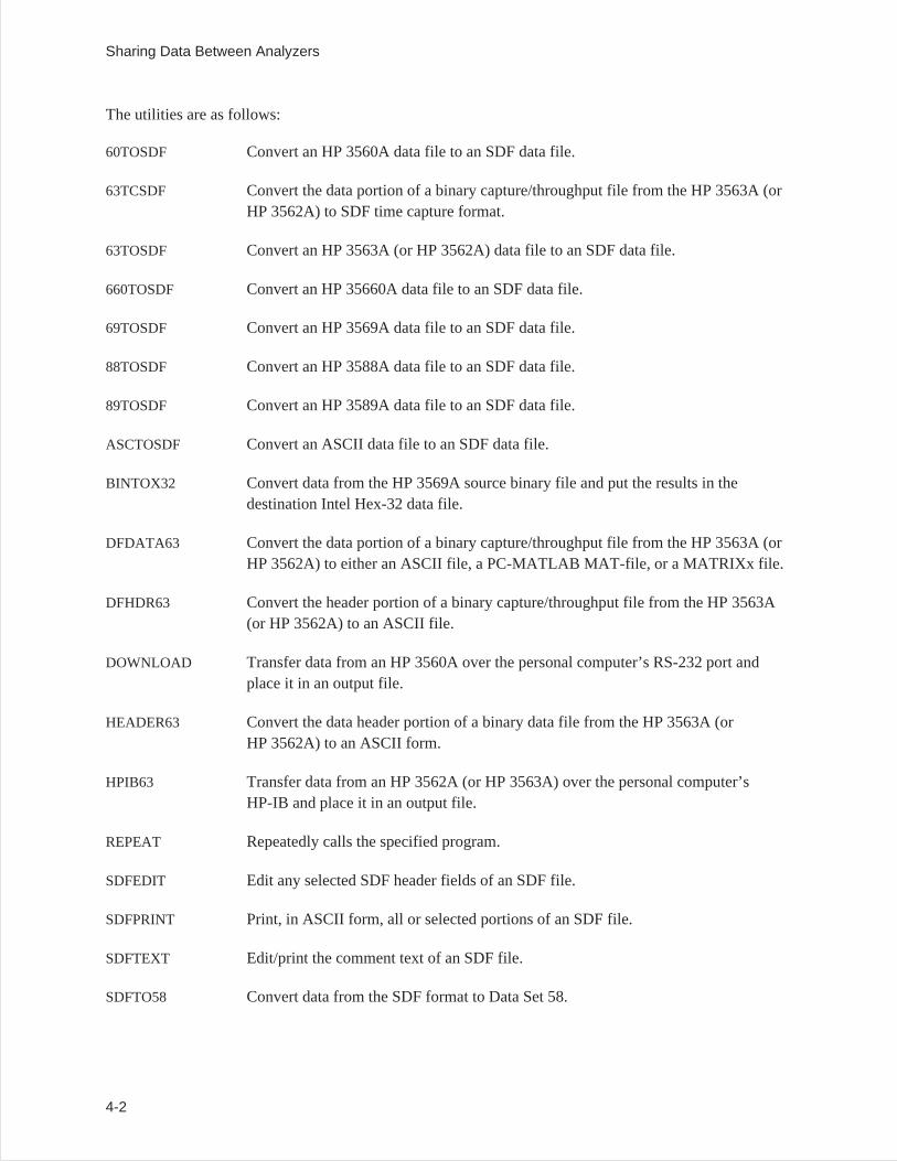
The utilities are as follows:
60TOSDF Convert an HP 3560A data file to an SDF data file.
63TCSDF Convert the data portion of a binary capture/throughput file from the HP 3563A (orHP 3562A) to SDF time capture format.
63TOSDF Convert an HP 3563A (or HP 3562A) data file to an SDF data file.
660TOSDF Convert an HP 35660A data file to an SDF data file.
69TOSDF Convert an HP 3569A data file to an SDF data file.
88TOSDF Convert an HP 3588A data file to an SDF data file.
89TOSDF Convert an HP 3589A data file to an SDF data file.
ASCTOSDF Convert an ASCII data file to an SDF data file.
BINTOX32 Convert data from the HP 3569A source binary file and put the results in thedestination Intel Hex-32 data file.
DFDATA63 Convert the data portion of a binary capture/throughput file from the HP 3563A (orHP 3562A) to either an ASCII file, a PC-MATLAB MAT-file, or a MATRIXx file.
DFHDR63 Convert the header portion of a binary capture/throughput file from the HP 3563A(or HP 3562A) to an ASCII file.
DOWNLOAD Transfer data from an HP 3560A over the personal computer’s RS-232 port andplace it in an output file.
HEADER63 Convert the data header portion of a binary data file from the HP 3563A (orHP 3562A) to an ASCII form.
HPIB63 Transfer data from an HP 3562A (or HP 3563A) over the personal computer’sHP-IB and place it in an output file.
REPEAT Repeatedly calls the specified program.
SDFEDIT Edit any selected SDF header fields of an SDF file.
SDFPRINT Print, in ASCII form, all or selected portions of an SDF file.
SDFTEXT Edit/print the comment text of an SDF file.
SDFTO58 Convert data from the SDF format to Data Set 58.
Sharing Data Between Analyzers
4-2
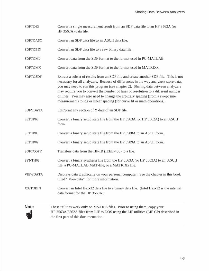
SDFTO63 Convert a single measurement result from an SDF data file to an HP 3563A (orHP 3562A) data file.
SDFTOASC Convert an SDF data file to an ASCII data file.
SDFTOBIN Convert an SDF data file to a raw binary data file.
SDFTOML Convert data from the SDF format to the format used in PC-MATLAB.
SDFTOMX Convert data from the SDF format to the format used in MATRIXx.
SDFTOSDF Extract a subset of results from an SDF file and create another SDF file. This is notnecessary for all analyzers. Because of differences in the way analyzers store data,you may need to run this program (see chapter 2). Sharing data between analyzersmay require you to convert the number of lines of resolution to a different numberof lines. You may also need to change the arbitrary spacing (from a swept sinemeasurement) to log or linear spacing (for curve fit or math operations).
SDFYDATA Edit/print any section of Y data of an SDF file.
SETUP63 Convert a binary setup state file from the HP 3563A (or HP 3562A) to an ASCIIform.
SETUP88 Convert a binary setup state file from the HP 3588A to an ASCII form.
SETUP89 Convert a binary setup state file from the HP 3589A to an ASCII form.
SOFTCOPY Transfers data from the HP-IB (IEEE-488) to a file.
SYNTH63 Convert a binary synthesis file from the HP 3563A (or HP 3562A) to an ASCIIfile, a PC-MATLAB MAT-file, or a MATRIXx file.
VIEWDATA Displays data graphically on your personal computer. See the chapter in this booktitled ‘’Viewdata’’ for more information.
X32TOBIN Convert an Intel Hex-32 data file to a binary data file. (Intel Hex-32 is the internaldata format for the HP 3560A.)
Note These utilities work only on MS-DOS files. Prior to using them, copy yourHP 3563A/3562A files from LIF to DOS using the LIF utilities (LIF CP) described inthe first part of this documentation.
Sharing Data Between Analyzers
4-3
Hardware and Software Requirements
Use of these utilities requires an IBM PC compatible with the MS-DOS 2.1 operating system(or greater).
HP 3563A/3562A File Format
When the HP 3563A/3562A saves measurement data or instrument states to an HP-IB disk drive, the filesare saved in a non-standard binary format used by the instrument. Typically, you need to transfer threepieces of information: your setup state, file header information, and measurement data. A setup state willbe in a single file, while the header information will be attached to a data file. Using these utilities, youcan separate header and data information into two files.
When you look at these files using the LIF utility commandLIF LS /L, you’ll see that the analyzers filesare all type BDAT. The first two letters in the file name indicate the file type:
File type: File name starts with:
Data DA
Setup State SE
Synthesis ST
Curve Fit(Z domain)
CVZF
Capture CS
Throughput TS
Online Help
Online Help is available for each conversion utility command. For a description of a particular commandand a list of its options, simply type the command name and /U.
For example, to get help on the command 63TOSDF, type:
63TOSDF /U [Enter ]
Sharing Data Between Analyzers
4-4
60TOSDF
Convert data from the HP 3560A source data file and put results in the destination SDF file. Thedestination SDF filename is chosen based on the register value that was used in the HP 3560A and is ofthe form <register number>.DAT (for example 1.DAT).
Syntax 60TOSDF <sfile> [/U] [/O] [/H] [/A] [/P:<c,p,d>]
Options
<sfile> Input HP 3560A data file name.
/U Show help (usage information) for this program.
/O Overwrite <dfile> if it exists.
/H Print headers to the screen.
/A Print headers and data to the screen.
/P:<c,p,d> Set point and direction for a channel (/P:), <c>is the channel number (0 or 1), <p> isthe point number, and <d> is the direction as follows:
0 None 5 Theta
1 X 6 Phi
2 Y 7 TX
3 Z 8 TY
4 Radial 9 TZ
Example
Transfer an HP 3560A data file (which is in Intel Hex-32 format) to a file (FREQ.X32) on a personalcomputer using the RS-232 port. Convert the Intel Hex-32 file to a binary data file (FREQ.BIN) and thenconvert the binary file to an SDF data file. The data file name is the same as the register number on theHP 3560A (for example, 1.DAT).
DOWNLOAD FREQ.X32 /B:19200 /P:2X32TOBIN FREQ.X32 FREQ.BIN60TOSDF FREQ.BIN
See also the batch file ‘’60_SDF.BAT’’ in appendix C.
Sharing Data Between Analyzers60TOSDF
4-5
63TCSDF
Convert the data portion of a binary capture/throughput file from the HP 3563A (or HP 3562A) to SDFtime capture format (16-bit integer data). The binary capture/throughput file contains digital filter data.The HP 3563A/62A capture files on a LIF file system start with the letters ‘’CS’’. Throughput files startwith ‘’TS’’.
Syntax 63TCSDF <sfile> <dfile> [/U] [/O]
Options
<sfile> Input HP 3563A/62A capture or throughput file name.
<dfile> Output SDF file name.
/U Show help (usage information) for this program.
/O Overwrite <dfile> if it exists.
Example
Copy a capture file (CSCAPTUR) from the HP 3563A LIF formatted disk drive (drive B:) to a file(CAPTUR.63) on the current hard drive and convert it to SDF format (CAPTUR.TIM):
LIF CP B:CSCAPTUR CAPTUR.6363TCSDF CAPTUR.63 CAPTUR.TIM
Sharing Data Between Analyzers63TCSDF
4-6
63TOSDF
Convert an HP 3563A (or HP 3562A) data file <sfile> to an SDF data file and outputs to <dfile>.HP 3563A/62A data files on a LIF file system start with the letters ‘’DA.’’
Syntax 63TOSDF <sfile> <dfile> [/U] [/O]
Options
<sfile> Input HP 3563A/62A data file name.
<dfile> Output SDF file name.
/U Show help (usage information) for this program.
/O Overwrite <dfile> if it exists.
Example
Copy a data file (DAFREQ) from the HP 3563A LIF formatted disk (drive B:) to a file (FREQ.63) on thecurrent hard drive and convert it to SDF format (FREQ.DAT):
LIF CP B:DAFREQ FREQ.6363TOSDF FREQ.63 FREQ.DAT
Discussion
A baseband time record contains 2048 real points, a zoom time record contains 1024 complex points, anda spectrum contains either 801 real or complex points or 1024 real or complex points.
See also the batch file ‘’63_SDF.BAT’’ in appendix C.
Sharing Data Between Analyzers63TOSDF
4-7
660TOSDF
Extract data from an HP 35660A data file <sfile> and put results in the SDF data file <dfile>.
Syntax 660TOSDF <sfile> <dfile> [/U] [/O] [/H] [/A]
Options
<sfile> Input HP 35660A data file name.
<dfile> Output SDF file name.
/U Show help (usage information) for this program.
/O Overwrite <dfile> if it exists.
/H Print headers to the screen.
/A Print headers and data to the screen.
Example
Copy a data file (TRACE1) from the HP 35660A LIF formatted disk (drive B:) to a file (FREQ.660) onthe current hard drive, then convert the file to SDF format (FREQ.DAT):
LIF CP B:TRACE1 FREQ.660660TOSDF FREQ.660 FREQ.DAT
Sharing Data Between Analyzers660TOSDF
4-8
69TOSDF
Convert data from the HP 3569A source data file and put results in the destination SDF file. If [dfile] isnot specified, the destination SDF filename is chosen based on the filename that was used in theHP 3569A and is of the form <filename>.DAT (for example, 1.DAT).
If the input X32 file contains more than 1 HP 3569A trace file (SAVE/RECALL, XFER ALL TRACES),then each trace will be put in a different file with the same base name as used on the HP 3569A. If [dfile]is specified, only the first trace in the file is used.
Syntax 69TOSDF <sfile> [dfile] [/U] [/O] [/H] [/A] [/P:c,p,d][/M:<value>][/D:<value>]
Options
<sfile> Input HP 3569A data file name.
[dfile] Optional output SDF data file name.
/U Show help (usage information) for this program.
/O Overwrite [dfile] if it exists.
/H Print headers to the screen.
/A Print headers and data to the screen.
/P:c,p,d Set point and direction for a channel (/P:). <c>is the channel number (0 or 1),<p> is the point number, and <d> is the direction as follows:
0 None 5 Theta
1 X 6 Phi
2 Y 7 TX
3 Z 8 TY
4 Radial 9 TZ
/M:<value> Set microphone separation for FFT Intensity data in mm.
/D:<value> Set density for FFT Intensity data in Kg/m3
Sharing Data Between Analyzers69TOSDF
4-9
Example
Transfer an HP 3569A data file (which is in Intel Hex-32 format) to a file (FREQ.X32) on a personalcomputer using the RS-232 port. Convert the Intel Hex-32 file to a binary data file (FREQ.BIN) and thenconvert the binary file to an SDF data file (FREQ.DAT).
DOWNLOAD /B:19200 /P:2 FREQ.X32X32TOBIN FREQ.X32 FREQ.BIN69TOSDF FREQ.BIN FREQ.DAT
See also the batch file ‘’69_SDF.BAT’’ in appendix C.
Sharing Data Between Analyzers69TOSDF
4-10
88TOSDF
Converts an HP 3588A data file <sfile> to an SDF data file and outputs to <dfile>. An HP 3588A setupstate file <hfile> can be optionally specified which will allow more complete parameter conversion intothe SDF data file.
Syntax 88TOSDF <sfile> <dfile> [/O] [/U] [/F <hfile>]
Options
<sfile> Input HP 3588A data file name.
<dfile> Output SDF file name.
/O Overwrite <dfile> if it already exists.
/U Show help (usage information) for this program.
/F Read HP 3588A setup state file for additional information.
<hfile> HP 3588A setup state path and file name.
Example
Copy a measurement data and setup state file from the HP 3588A LIF formatted disk and convert it toSDF format:
LIF CP B:TRACE1 TRACE1.88LIF CP B:STATE1 STATE1.8888TOSDF TRACE1.88 TRACE1.DAT /F STATE1.88
Sharing Data Between Analyzers88TOSDF
4-11
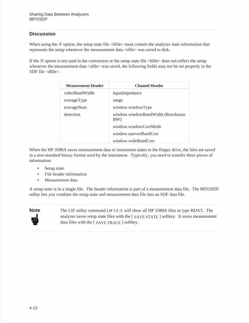
Discussion
When using the /F option, the setup state file <hfile> must contain the analyzer state information thatrepresents the setup whenever the measurement data <sfile> was saved to disk.
If the /F option is not used in the conversion or the setup state file <hfile> does not reflect the setupwhenever the measurement data <sfile> was saved, the following fields may not be set properly in theSDF file <dfile>.
Measurement Header Channel Header
videoBandWidth inputImpedance
averageType range
averageNum window.windowType
detection window.windowBandWidth (ResolutionBW)
window.windowCorrMode
window.narrowBandCorr
window.wideBandCorr
When the HP 3588A saves measurement data or instrument states to the floppy drive, the files are savedin a non-standard binary format used by the instrument. Typically, you need to transfer three pieces ofinformation:
• Setup state• File header information• Measurement data
A setup state is in a single file. The header information is part of a measurement data file. The 88TOSDFutility lets you combine the setup state and measurement data file into an SDF data file.
Note The LIF utility commandLIF LS /L will show all HP 3588A files as type BDAT. Theanalyzer saves setup state files with the [SAVE STATE] softkey. It saves measurementdata files with the [SAVE TRACE] softkey.
Sharing Data Between Analyzers88TOSDF
4-12
89TOSDF
Converts an HP 3589A data file <sfile> to an SDF data file and outputs to <dfile>. An HP 3589A setupstate file <hfile> can be optionally specified which will allow more complete parameter conversion intothe SDF data file.
Syntax 89TOSDF <sfile> <dfile> [/O] [/U] [/F <hfile>]
Options
<sfile> Input HP 3589A measurement data path and file name.
<dfile> Output SDF path and file name.
/O Overwrite <dfile> if it already exists.
/U Show help (usage information) for this program.
/F Read HP 3589A setup state file for additional information.
<hfile> HP 3589A setup state path and file name.
Example
Copy a measurement data and setup state file from the HP 3589A LIF formatted disk and convert it toSDF format:
LIF CP B:TRACE1 TRACE1.89LIF CP B:STATE1 STATE1.8989TOSDF TRACE1.89 TRACE1.DAT /F STATE1.89
Sharing Data Between Analyzers89TOSDF
4-13
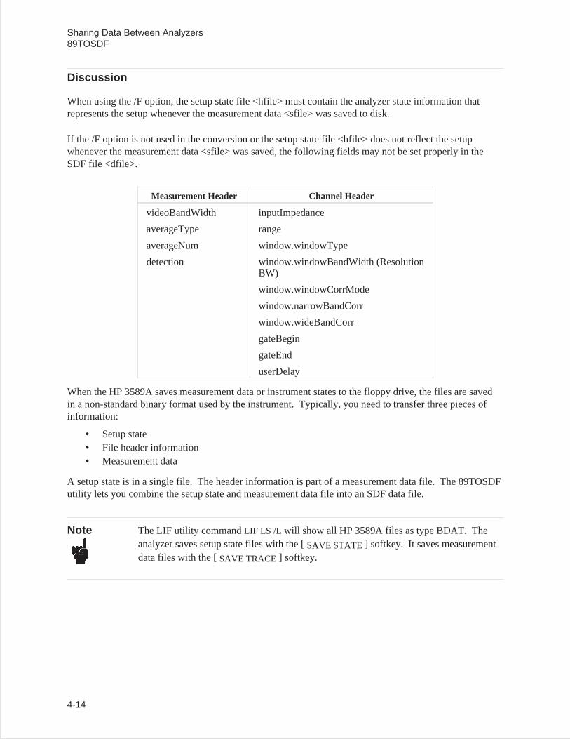
Discussion
When using the /F option, the setup state file <hfile> must contain the analyzer state information thatrepresents the setup whenever the measurement data <sfile> was saved to disk.
If the /F option is not used in the conversion or the setup state file <hfile> does not reflect the setupwhenever the measurement data <sfile> was saved, the following fields may not be set properly in theSDF file <dfile>.
Measurement Header Channel Header
videoBandWidth inputImpedance
averageType range
averageNum window.windowType
detection window.windowBandWidth (ResolutionBW)
window.windowCorrMode
window.narrowBandCorr
window.wideBandCorr
gateBegin
gateEnd
userDelay
When the HP 3589A saves measurement data or instrument states to the floppy drive, the files are savedin a non-standard binary format used by the instrument. Typically, you need to transfer three pieces ofinformation:
• Setup state• File header information• Measurement data
A setup state is in a single file. The header information is part of a measurement data file. The 89TOSDFutility lets you combine the setup state and measurement data file into an SDF data file.
Note The LIF utility commandLIF LS /L will show all HP 3589A files as type BDAT. Theanalyzer saves setup state files with the [SAVE STATE] softkey. It saves measurementdata files with the [SAVE TRACE] softkey.
Sharing Data Between Analyzers89TOSDF
4-14
ASCTOSDF
Convert the source file to the destination file and place the result in the destination file. The followingoptions are only valid when used with the /T (template SDF file) option; /D, /R, /C, /S. The optionsdescribed after the /T option are only used if a template SDF file is not specified.
Syntax ASCTOSDF <sfile> <dfile> [/U] [/O] [/D:<data>] [/R:<row>] [/C:<col>[ [/S:<scan>][/T:<sdffile>] [/H:<type>] [/B:<blksize>] [/L:<lines>] [/Z:<ctrFrq>] [/X:<s,d>[,L]]
Options
<sfile> Input ASCII file.
<dfile> Output SDF file.
/U Show help (usage information) for this program.
/O Overwrite <dfile> if it already exists.
/D:<data> Select data for the specified SDF_DATA_HDR. The default is 0.
/R:<row> Select data for the specified row. The default is 0.
/C:<col> Select data for the specified column. The default is 0.
/S:<scan> Select data for the specified scan. The default is 0.
/T:<sdffile> Template SDF file. If you already have a file (for example, a frequency responsefile) set up, use this option to copy that file and replace the data with the inputASCII file.
/H:<type> Create default headers, where type is:Time – time data (the default).LSpec – linear spectrumPSpec – power spectrumFRF – frequency response
Sharing Data Between AnalyzersASCTOSDF
4-15
/B:<blksize> Block size. Use this when the header type is Time. The default is the number ofpoints in the file.
/L:<lines> Frequency lines. Use this when the header type is not Time. The default is thenumber of lines in the file.
/Z:<ctrFrq> Turn on zoom and set Center Frequency (use when header type is TIME)
/X:<s,d>[,L] Generate X data. Start and Delta values are required. The optional [L] signifieslog. Otherwise linear is used.
Example
Convert an ASCII data file to an SDF file using the linear spectrum header and a 2048 block size:
ASCTOSDF TEST.TXT TEXT.DAT /H:LSPEC /L:800
Sharing Data Between AnalyzersASCTOSDF
4-16
BINTOX32
Convert data from the HP 3569A source binary file and put the results in the destination Intel Hex-32 datafile.
Syntax BINTOX32 <sfile> <dfile> [/U] [/O]
Options
<sfile> Input binary file name.
<dfile> Output Hex-32 file name.
/U Show help (usage information) for this program.
/O Overwrite <dfile> if it exists.
Example
Convert an HP 3569A binary data file (FREQ.BIN) to an Intel Hex-32 file (FREQ.X32):
BINTOX32 FREQ.BIN FREQ.X32
Sharing Data Between AnalyzersBINTOX32
4-17
DFDATA63
Converts the data portion of a binary capture/throughput file (containing digital filter time data) from theHP 3563A (or HP 3562A) to a PC-MATLAB MAT-file, a MATRIXx file, or an ASCII file. Sincecapture/throughput data can be very long, the /B and /P options can be used to select only a portion of thedata in a file. The /C option only needs to be specified for a 2 channel throughput file to select channel 2as the source of data. HP 3563A/62A capture files on a LIF file system start with the letters ‘’CS’’;throughput files start with the letters ‘’TS.’’
Syntax DFDATA63 <sfile> <dfile> [/U] [/O] [/L] [/M] [/R] [/X] [/B:<ofst>] [/P:<len>] [/C:<chan>]
Options
<sfile> Input HP 3563A/62A capture or throughput file name.
<dfile> Output file name.
/U Show help (usage information) for this program.
/O Overwrites <dfile> if it exists.
/L Create MATLAB file (a binary file).
/M Create MATRIXx file (an ASCII file).
/R Output MATLAB or MATRIXx file matrices in a row instead of a column.
/X Output X-axis data.
/B:<ofst> Offset from beginning of data (in points) to convert (default 0).
/P:<len> Length of data (in points) to convert (default 20480 points); MATLAB andMATRIXx files can contain up to 32767 points.
/C:<chan> Channel of data to convert (default channel 1 if there are 2 channels of data).
If neither /L nor /M option is specified, then an ASCII file is created.
Sharing Data Between AnalyzersDFDATA63
4-18
Example 1
Convert up to 4096 points of your file (GLITCH) to a PC-MATLAB file (GLITCH.MAT); includesX-axis data points. Note the PC-MATLAB searches for a file with the suffix ‘’.MAT’’ if no suffix isspecified. See appendix for more information on loading a file into PC-MATLAB.
DFDATA63 GLITCH C:GLITCH.MAT /L /X /P:4096
Example 2
Output channel 2 data (THRUPUT) to an ASCII file (THRUPT.ASC) after skipping the first 20480points of the data file:
DFDATA63 THRUPUT THRUPT.ASC /B:20480 /C:2
Discussion
Each capture/throughput record contains 2048 real points (baseband) or 1024 complex points (zoom). Acapture file contains up to 10 records of time data, whereas a throughput file contains up to 32767records. Since capture/throughput data can be very long, the /B and /P options can be used to select onlya portion of the data in a file. The /C option only needs to be specified for a 2 channel throughput file toselect channel 2 as the source of data.
An ASCII file contains one line for each data point (up to 3 fields separated by commas). If the /X optionis specified, the first field is the X-axis data value. The next field is the real part of the Y data point. Ifthe data is complex, then the last field is the imaginary part of the Y data point.
Both the PC-MATLAB and MATRIXx files contain the following matrix variables:
Trace X Vector of X values (only if /X is specified).
Start X Starting X value (only if /X is not specified).
IncrX Linear X increment between points (only if /X is not specified).
LogX Log X increment between points (only if /X is not specified). This value is always1.0.
TraceData Vector of Y values (may be complex).
If the /X option is not specified, the StartX and IncrX variables can be used to calculate the X data asfollows:
X = (Xlast + IncrX)
where Xlast is the previous point’s X and the first X is StartX.
Sharing Data Between AnalyzersDFDATA63
4-19
DFHDR63
Converts the header portion of a binary capture/throughput file <sfile> (containing digital filter data) fromthe HP 3563A (or HP 3562A) to an ASCII form <dfile>. Refer to the HP 3563A or HP 3562AProgramming Manualfor descriptions of the individual fields in the capture/throughput file.HP 3563A/62A capture files on a LIF file system start with the letters ‘’CS’’; throughput files start withthe letters ‘’TS.’’
Syntax DFHDR63 <sfile> [dfile] [/U] [/O] [/L:<flag>] [/E:<flag>]
Options
<sfile> Input HP 3563A/62A capture or throughput file name.
[dfile] Output file name.
/U Show help (usage information) for this program.
/O Overwrites [dfile] if it exists.
/L:<flag> If <flag> is non-zero, put labels on each line. The name of each field will be thefirst 25 characters of each line (approximately as they appear in the HP 3563A orHP 3562AProgramming Manual). The default is on.
/E:<flag> If <flag> is non-zero, expand enumerated types to ASCII names (approximately asthey appear in the HP 3563A or HP 3562AProgramming Manual). The default ison.
Sharing Data Between AnalyzersDFHDR63
4-20
Example
After copying the capture/throughput file to your PC,using the LIF CP command (LIF CP 702:CSGLITCHGLITCH), type:
DFHDR63 GLITCH GLITCH.ASC
The file GLITCH.ASC will include a list such as the following.
Complex_data)_flag FalseBytes_per_point 2Points_per_record 2048Channel_type. Channel_1Bandwidth_units HertzX_units HertzDelay_channel Channel_2Delay_count 0Partial_record 0Interleave 0#_of_realtime_records 10Sectors_per_track 0Skip_track_[1] 0
Discussion
The destination file contains one line for each field in the capture/throughput header. Refer to theHP 3563A or HP 3562AProgramming Manualfor descriptions of the individual fields in the data file.All integers, reals, and long reals will be converted to ASCII, strings will be surrounded by double quotes(“), and enumerated types will be converted to ASCII integers (if /E:0 is specified).
Sharing Data Between AnalyzersDFHDR63
4-21
DOWNLOAD
Transfer data over the personal computer’s RS-232 port and place it in the destination file.
Syntax DOWNLOAD <dfile> [/U] [/O] [/B:<baud>] [/P:<port>]
Options
<dfile> Output file name.
/U Show help (usage information) for this program.
/O Overwrite <dfile> if it exists.
/B:<baud> Select the baud rate for the communications port. Valid baud rates are 110, 150,300, 600, 1200, 2400, 4800, 9600, or 19200. The default value is 9600.
/P:<port> Select the communications port number. Valid port numbers are 1 – 4. The defaultvalue is 1.
Example
Transfer a data file to a file (FREQ.X32) on a personal computer, using the RS-232 port (port 2).
DOWNLOAD FREQ.X32/B:19200 /P:2
See also the batch files ‘’60_SDF.BAT’’ and ‘’69_SDF.BAT’’ in appendix C.
Sharing Data Between AnalyzersDOWNLOAD
4-22
HEADER63
Converts the data header portion of a binary data file <sfile> from the HP 3563A (or HP 3562A) to anASCII form [dfile]. Refer to the HP 3563A or HP 3562AProgramming Manualfor descriptions of theindividual fields in the data file. HP 3563A and HP 3562A data files on a LIF file system start with theletters ‘’DA.’’
Syntax HEADER63 <sfile> [dfile] [/U] [/O] [/L:<flag>] [/E:<flag>]
Options
<sfile> Input HP 3563A/62A data file name.
[dfile] Optional output SDF file name. If no file name is specified, output to display.
/U Show help (usage information) for this program.
/L:<flag> If <flag> is non-zero, put labels on each line. The name of each field will be thefirst 25 characters of each line (approximately as they appear in the HP 3563A orHP 3562AProgramming Manual). The default is on.
/E:<flag> If <flag> is non-zero, expand enumerated types to ASCII names (approximately asthey appear in the HP 3563A or HP 3562AProgramming Manual). The default ison.
Sharing Data Between AnalyzersHEADER63
4-23

Example
After copying the data file to your PC, using the LIF CP command (LIF CP 702:DAFREQ FREQ1), type:
HEADER63 FREQ1 FREQ1.ASC /L:0
The file FREQ1.ASC will include a list, such as the following.
Power_spectrum_18018011Channel_1No_channel87Freq uencyRMSVolts_squaredHertz“AUTO MATH”“”“”“”TrueFa lse
Discussion
The destination file contains one line for each field in the data header. Refer to the HP 3563A orHP 3562AProgramming Manualfor description of the individual fields in the data file.
• All integers, reals, and long reals will be converted to ASCII.• Strings will be surrounded by double quotes (“).• Enumerated types will be converted to ASCII integers (if /E:0 is specified).
Sharing Data Between AnalyzersHEADER63
4-24
HPIB63
Transfer the active trace data from an HP 3562A/63A over the personal computer’s HP-IB and place it inthe destination file. Use 63TOSDF.EXE to convert the file to SDF. If /A is not specified, then HP-IBwill be scanned for the first instrument that is an HP 3562A or HP 3563A.
Syntax HPIB63 <dfile> [/U] [/O] [/I] [/A:<hpibAdr>]
Options
<dfile> Destination HP 3562A/63A file name
/U Show this usage.
/O Overwrite <dfile> if it exists.
/I Show information on all instruments connected to HP-IB.
/A:<hpibAdr> Specify the HP-IB address of the instrument.
Example
Transfer the active trace to a file (FREQ.63) on a personal computer (let HPIB63 find the instrument) andconvert it to ASCII.
HPIB63 FREQ.6363TOSDF FREQ.63 FREQ.DATSDFTOASC FREQ.DAT
See also the batch files ‘’IB63_ML.BAT’’, ‘’IB63_MX.BAT’’, ‘’IB63_PLT.BAT’’, and‘’IB63_SDF.BAT’’ in appendix C.
Sharing Data Between AnalyzersHPIB63
4-25
REPEAT
Repeatedly calls the specified program, varying the file name (with wild cards) and the destination filename, or all the results/rows/columns/scans in the specified file(s).
Syntax REPEAT [/U] [/I] [/E] [/A] [<program>] [/D:*] [/R:*] [/C:*] [/S:*] <sfile> [(dfile)]
Options
<program> Program to REPEAT.
/U Show this usage.
/I Ignore errors.
/E Echo commands before executing program.
/A Append to destination path.
/D:* Repeat for all data results.
/R:* Repeat for all rows in the specified data result(s).
/C:* Repeat for all columns in the specified data result(s).
/S:* Repeat for all scans in the specified data result(s).
<sfile> Source path and file name for SDF file. Repeat for all file(s ) by specifying wildcard file name.
[(dfile)] Destination path and file name. It may contain wild card (e.g. *.asc) to match thebase name in the <sfile> or pound sign (e.g. #.asc) for sequencing the file name(e.g. 0.asc, 1.asc, etc.) and must have an open/close parentheses. The destinationfile may be included in an option (e.g. /P: (*.plt) for viewdata).
Sharing Data Between AnalyzersREPEAT
4-26
Example
To convert all the scans in MAP.DAT to ASCII and put each scan in a different file (e.g. 0.asc,1.asc, etc.):
REPEAT SDFTOASC /S:* MAP.DAT (#.ASC)
Same as above, but append all ASCII data to one file (e.g. map.asc):
REPEAT /A SDFTOASC /S:* MAP.DAT (MAP.ASC)
Plot all results/rows/scans in all *.dat files and put all plotted results for each file in a plot file with thesame base name as the data file (e.g. *.plt):
REPEAT /A VIEWDATA /D:* /R:* /S:* *.DAT /P:(*.PLT)
Sharing Data Between AnalyzersREPEAT
4-27
SDFEDIT
Edit (change) header fields in an SDF file. Fields are not case sensitive and may be abbreviated. Multiplefields and Multiple SDF header types may be specified. If no field is specified, then all fields in theheader are displayed.
Syntax SDFEDIT <file> [/U] [/I] [/F] [/M] [/D:<data>] [/V:<vect>] [/C:<chan>] [/S] [/T:<com-ment>] [/B:<bigScan>] [/N:<scanVar>] [/Q:<unique>] <field>=<value> ...
Options
<file> SDF file to edit.
/U Show this usage.
/I Information only on <file> (i.e. measurement results available).
/F Edit SDF_FILE_HDR.
/M Edit SDF_MEAS_HDR.
/D:<data> Edit specified SDF_DATA_HDR.
/V:<vect> Edit specified SDF_VECTOR_HDR.
/C:<chan> Edit specified SDF_CHANNEL_HDR.
/S Edit SDF_SCAN_HDR.
T:<comment> Edit specified SDF_COMMENT_HDR
B:<bigScan> Edit specified SDF_SCAN_BIG (default 0)
N:<scanVar> Edit specified SDF_SCAN_VAR (default 1)
Q:<unique> Edit specified SDF_HDR (Unique)
<field>=<value> Field to change with the specified value. An Enumerated Integer may be specifiedby its integer value or name.
<field> Display current value of field.
<field>= Display type of field. For an Enumerated Integer, this also shows the namesassociated with the integer values.
Sharing Data Between AnalyzersSDFEDIT
4-28
Example
To change the point and/or direction on an already existing SDF file, see the following SDFEDITexample:
To change the point number for channel 0 in the file test.dat to point 52 type:
sdfedit test.dat /c:0 point=52
To see the current point number type:
sdfedit test.dat /c:0 point
To see the choices for direction for channel 0 type:
sdfedit test.dat /c:0 direction=
or
sdfedit test.dat /c:0 dir=
You can abbreviate field names. To set the direction to ‘TX__DIRECTION’
sdfedit test.dat /c:0 direction=TX_DIRECTION
or
sdfedit test.dat /c:0 dir=tx
or
sdfedit test.dat /c:0 dir=7
To see all the field names (and current values) in the channel header type:
sdfedit test.dat /c:0
You can set multiple fields at the same time. To set the point to 5 and the direction to Z_DIRECTIONtype:
sdfedit test.dat /c:0 POINT=5 DIRECTION=Z_DIRECTION
or
sdfedit test.dat /c:0 poi=5 dir=z
This example also shows that the field names and the selection names are NOT case sensitive. You canchange fields in more than one header at the same time. To set the point to 2 in theSDF_CHANNEL_HDR and the measTitle to ‘’this title’’, type:
sdfedit test.dat /m meastitle="this title" /c:0 poi=2
This example also shows that setting a field value that includes blanks requires you to put quotes aroundthe field value.
Sharing Data Between AnalyzersSDFEDIT
4-29
SDFPRINT
Converts the contents of the input SDF file <sfile> to ASCII and prints all or portions of it. Either theSDF record headers (default) and/or the data associated with the SDF_SCAN_HDR, XDATA, YDATA,and comment records may be printed.
Syntax SDFPRINT <sfile> [dfile] [/U] [/O] [/I] [/V] [/H] [/T:<type>] [/A] [N:<#perLine>][/D:<data>] [/S:<scan>] [/R:<row>] [/C:<col>] [/P:<flag>] [/E:<flag>] [/W:<flag>]
Options
<sfile> Input file name for SDF file.
[dfile] Optional output file name for ASCII information (default is the display).
/U Show help (usage information) for this program.
/O Overwrites [dfile] if it exists.
/I Show information only on <sfile>, including data result number, result name, thenumber of rows, columns, scans available, the number of data points, whether thedata is real or complex, and type of X spacing between data points.
/V Validate SDF file (does consistency check).
/H Print just the SDF record headers (default).
/T:<type> Print data for SDF SCAN (/T:S), X (/T:X), Y (/T:Y) data, unique records (/T:U), orcomment records (/T:C). If /T is specified, all data is printed.
/A Print both headers and data.
/N:<#perLine> Numbers of data for each printed line. The default is 1.
/D:<data> Print data only for the specified data result (see figure 2-1). If not specified, then allresults in <sfile> will be selected.
/S:<scan> Print data only for the specified scan (see figure 2-3). If not specified, then all scansin <sfile> will be selected.
/R:<row> Print data only for the specified row (see figure 2-2). If not specified, then all rowsin <sfile> will be selected.
Sharing Data Between AnalyzersSDFPRINT
4-30
/C:<col> Print data only for the specified column. If not specified, then all columns in<sfile> will be selected.
/P:<flag> If <flag> is non-zero, print SDF record titles (default on).
/E:<flag> If <flag> is non-zero, expand enums to labels (default on).
/W:<flag> If <flag> is non-zero, scale the data for the window and engineering units. (defaulton).
Example
To find out what results are available in an SDF measurement results file from HP 3566A/67A (sweptsine measurement):
SDFTO63 /I SINEARB.DAT
This will produce a list on the display such as the following.
Data Name Rows Cols Scans Points Complex Space
0 Freq Response 103 Arb1 Nrml Variance 2 103 Arb2 Input Power Ch1 103 Arb3 Output Power Ch2 103 Arb4 Cross Power 103 Arb
This example shows 5 data results (0 thru 4) are available with 103 arbitrarily spaced points (indicative ofswept sine data, see figure 2-1).
The ‘’Rows’’ field (if present) is usually associated with the number of channels of data available forsingle channel results (see figure 2-2). For example, 2 channels of ‘’Normalized Variance’’ measurementresults are present.
At this time, the ‘’Columns’’ field is not used (there is always only 1 column of data) by any instrumentusing SDF as a data format.
The ‘’Scans’’ field indicates that the data contains Waterfall results from HP 3566A/67(see figure 2-3).
Sharing Data Between AnalyzersSDFPRINT
4-31
To print all the headers to this SDF file type:
SDFPRINT SINEARB.DAT
To print only the data for ‘’Normalized Variance’’ channel 2 (row 0 is channel 1, row 1 ischannel 2) type:
SDFPRINT SINEARB.DAT /D:1 /R:1
To now print this data in pure ASCII with no record headers:
SDFPRINT SINEARB.DAT /D:1 /R:1 /P:0
Discussion
The HP 3566A/67A generally puts all results from a measurement in a single file (seeexample above).
The following types of records are present in an SDF file:
Name Description
SDF_FILE_HDR Provides an index to the file.
SDF_MEAS_HDR Contains settings of measurement parameters.
SDF_DATA_HDR Information on one type of measurement result (X/Y info). Onemeasurement result can contain many rows (e.g. channels) of dataresults.
SDF_VECTOR_HDR Information on which channels were used for each data result. There isone SDF_VECTOR_HDR for each row (& column) of data in ameasurement result. Each SDF_VECTOR_HDR may reference up to 2channels.
SDF_CHANNEL_HDR Contains channel-specific information for one channel used in ameasurement.
UNIQUE record Contains instrument-specific information.
SDF_SCAN_STRUCT Tells you how vectors are organized in the Y-axis Data record when themeasurement includes multiple scans of data.
SDF_SCAN_BIG Tells you how vectors are organized in the Y-axis Data record when themeasurement includes a large number of scans of data.
SDF_SCAN_VAR Information about each scan. This is for measurements that includemultiple scans of data.
Sharing Data Between AnalyzersSDFPRINT
4-32
SDF_COMMENT_HDR Contains comments about the data.
XDATA Contains the X-axis data needed to reconstruct a trace. This can be usedby Swept Sine or Order Analysis measurements.
YDATA Contains the Y-axis data needed to reconstruct any trace.
Sharing Data Between AnalyzersSDFPRINT
4-33
SDFTEXT
Modify/print SDF file <sfile> comment text data. If [cfile] is specified then the comment in the SDF fileis modified, otherwise the comment is printed. If the /A option is not specified, then the previouscomment in the file is replaced with [cfile]. If there is not enough space in the specified comment for thetext, then the text will be truncated.
If no space was allocated for the comment area by the instrument us SDFTOSDF with the /M option tocreate a comment area in the SDF file.
Syntax SDFTEXT <sfile> [cfile] [/U] [/T:<comment>] [/A]
Options
<sfile> SDF file.
[cfile] Input ASCII comment file.
/U Show this usage.
/T:<comment> Select specified SDF_COMMENT_HDR (default 0).
/A Append text to end of comment in file.
Example
SAMPLE.TXT contains some ASCII text.
SDFTEXT TIME.DAT SAMPLE.TXT /A
This command appends the contents of SAMPLE.TXT to the end of the TIME.DAT SDF file commentarea.
Sharing Data Between AnalyzersSDFTEXT
4-34
SDFTO58
Convert SDF file <sfile> to the Data Set 58 format. The result is placed in an output file [dfile] ifspecified; otherwise the result is sent to the screen.
Syntax SDFTO58 <sfile> [dfile] [/U] [/O] [/I] [/A] [/H] [/D:N1[-N2]] [/R:N1[-N2]] [/C:N1[-N2]][/S:N1[-N2]]
Options
<sfile> Input SDF file name.
[dfile] Optional output file name for ASCII information. If no file name is specified,output to display.
/U Show help (usage information) for this program.
/O Overwrite [dfile] if it exists.
/I Show information only on <sfile>, including data result number, result name, thenumber of rows, columns, scans available, the number of data points, whether thedata is real or complex, and type of X spacing between data points.
/A Convert all frequency lines (normally the lines likely to be affected by aliasing arenot converted)
/H Do not output header records (allows you to output an array of data only)
/D:N1[-N2] Convert the data at data number N1 (to data number N2). Range; 0 to n–1.
/R:N1[-N2] Convert the data at row N1 (to row N2). Range; 0 to n–1.
/C:N1[-N2] Convert the data at column N1 (to column N2). Range; 0 to n–1.
/S:N1[-N2] Convert the data at scan N1 (to scan N2). Range; 0 to n–1.
Sharing Data Between AnalyzersSDFTO58
4-35
SDFTO63
Converts a single measurement result from an SDF data file <sfile> to an HP 3563A (or HP 3562A) datafile <dfile>. HP 3563A/62A data files on a LIF system start with the letters ‘’DA.’’
Syntax SDFTO63 <sfile> <dfile> [/U] [/O] [/I] [/D:<data>] [/S:<scan>] [/R:<row>] [/C:<col>]
Options
<sfile> Input SDF file name.
<dfile> Output file name for HP 3563A/62A data file. The file name must begin with DA,for example DATRACE1, if you plan to use LIF CP on the file.
/U Show help (usage information) for this program.
/O Overwrite <dfile> if it exists.
/I Show information only on <sfile>, including data result number, result name, thenumber of rows, columns, scans available, the number of data points, whether thedata is real or complex, and type of X spacing between data points.
/D:<data> Select data result for the specified SDF_DATA_HDR. If not specified, then thefirst result (result 0) in <sfile> will be selected. Use /I to see a list of the resultnames and numbers.
/S:<scan> Select data for the specified scan (map line or waterfall step, see figure 2-3). If notspecified, then the first scan (scan 0) in <sfile> will be selected.
/R:<row> Select data for the specified row (see figure 2-2). If not specified, then the first row(row 0) in <sfile> will be selected.
/C:<col> Select data for the specified column. If not specified, then the first column (column0) in <sfile> will be selected. At this time, the ‘’Columns’’ field is not used (thereis always only 1 column of data) by any instrument using SDF as a data format.
Sharing Data Between AnalyzersSDFTO63
4-36
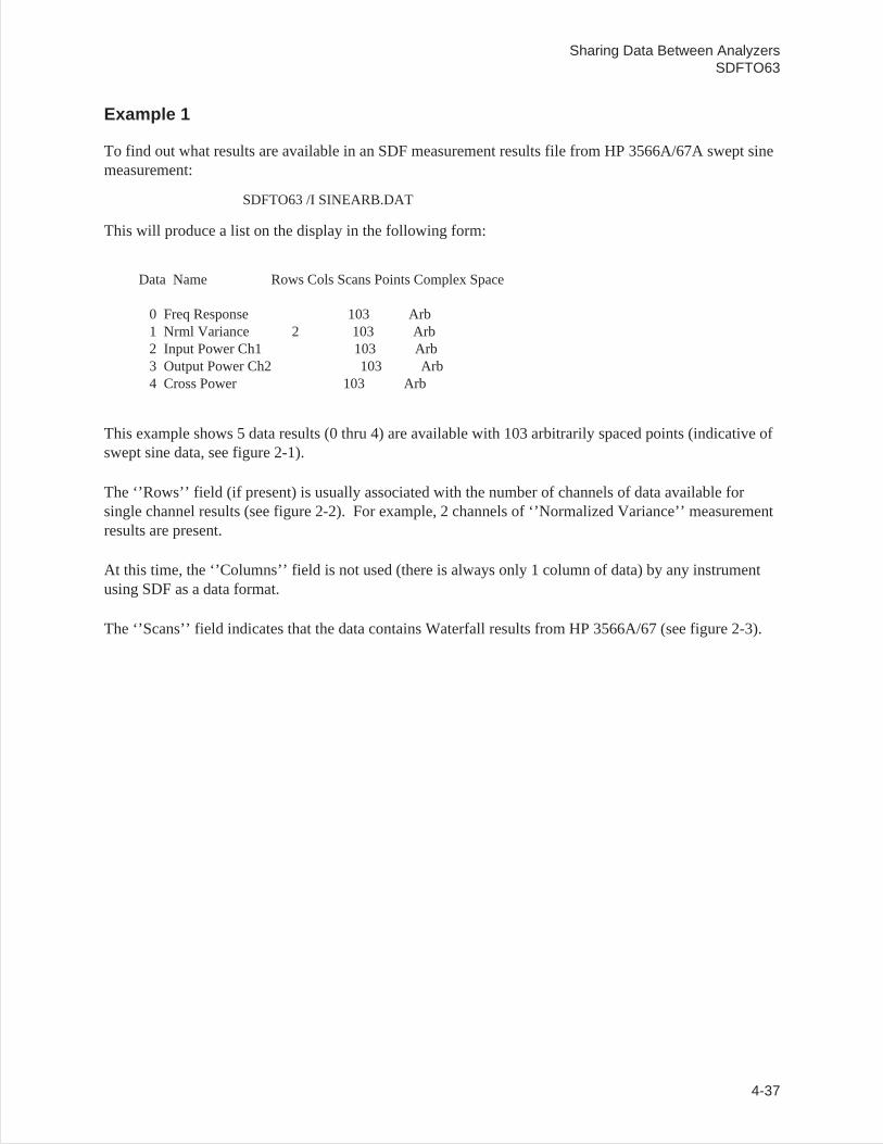
Example 1
To find out what results are available in an SDF measurement results file from HP 3566A/67A swept sinemeasurement:
SDFTO63 /I SINEARB.DAT
This will produce a list on the display in the following form:
Data Name Rows Cols Scans Points Complex Space
0 Freq Response 103 Arb1 Nrml Variance 2 103 Arb2 Input Power Ch1 103 Arb3 Output Power Ch2 103 Arb4 Cross Power 103 Arb
This example shows 5 data results (0 thru 4) are available with 103 arbitrarily spaced points (indicative ofswept sine data, see figure 2-1).
The ‘’Rows’’ field (if present) is usually associated with the number of channels of data available forsingle channel results (see figure 2-2). For example, 2 channels of ‘’Normalized Variance’’ measurementresults are present.
At this time, the ‘’Columns’’ field is not used (there is always only 1 column of data) by any instrumentusing SDF as a data format.
The ‘’Scans’’ field indicates that the data contains Waterfall results from HP 3566A/67 (see figure 2-3).
Sharing Data Between AnalyzersSDFTO63
4-37
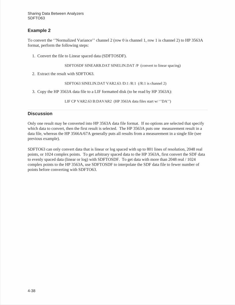
Example 2
To convert the ‘’Normalized Variance’’ channel 2 (row 0 is channel 1, row 1 is channel 2) to HP 3563Aformat, perform the following steps:
1. Convert the file to Linear spaced data (SDFTOSDF).
SDFTOSDF SINEARB.DAT SINELIN.DAT /P (convert to linear spacing)
2. Extract the result with SDFTO63.
SDFTO63 SINELIN.DAT VAR2.63 /D:1 /R:1 (/R:1 is channel 2)
3. Copy the HP 3563A data file to a LIF formatted disk (to be read by HP 3563A):
LIF CP VAR2.63 B:DAVAR2 (HP 3563A data files start w/ ‘’DA’’)
Discussion
Only one result may be converted into HP 3563A data file format. If no options are selected that specifywhich data to convert, then the first result is selected. The HP 3563A puts one measurement result in adata file, whereas the HP 3566A/67A generally puts all results from a measurement in a single file (seeprevious example).
SDFTO63 can only convert data that is linear or log spaced with up to 801 lines of resolution, 2048 realpoints, or 1024 complex points. To get arbitrary spaced data to the HP 3563A, first convert the SDF datato evenly spaced data (linear or log) with SDFTOSDF. To get data with more than 2048 real / 1024complex points to the HP 3563A, use SDFTOSDF to interpolate the SDF data file to fewer number ofpoints before converting with SDFTO63.
Sharing Data Between AnalyzersSDFTO63
4-38
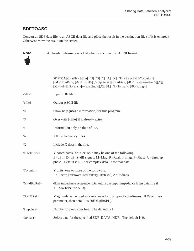
SDFTOASC
Convert an SDF data file to an ASCII data file and place the result in the destination file ( if it is entered).Otherwise view the result on the screen.
Note All header information is lost when you convert to ASCII format.
SDFTOASC <sfile> [dfile] [/U] [/O] [/I] [/A] [/X] [/T:<c1>,<c2>] [/Y:<units>][/M:<dBmRef>] [/G:<dBRef>] [/P:<points>] [/D:<data>] [/R:<row>[-<rowEnd>][,C]][/C:<col>] [/S:<scan>[−<scanEnd>][,C]] [/L] [/F:<format>] [/B:<string>]
<sfile> Input SDF file.
[dfile] Output ASCII file.
/U Show help (usage information) for this program.
/O Overwrite [dfile] if it already exists.
/I Information only on the <sfile>.
/A All the frequency lines.
/X Include X data in the file.
/T:<c1>,<c2> Y coordinates, <c1> or <c2> may be one of the following:B=dBm, D=dB, S=dB signed, M=Mag, R=Real, I=Imag, P=Phase, U=Unwrapphase. Default is R, I for complex data, R for real data.
/Y:<units> Y units, one or more of the following:L=Linear, P=Power, D=Density, R=RMS, A=Radians
/M:<dBmRef> dBm impedance reference. Default is use input impedance from data file if< 1 MΩ (else use 50Ω).
/G:<dBRef> Magnitude value used as a reference for dB type of coordinates. If /G with noparameter, then default is 20E-6 (dBSPL).
/P:<points> Number of points per line. The default is 1.
/D:<data> Select data for the specified SDF_DATA_HDR. The default is 0.
Sharing Data Between AnalyzersSDFTOASC
4-39
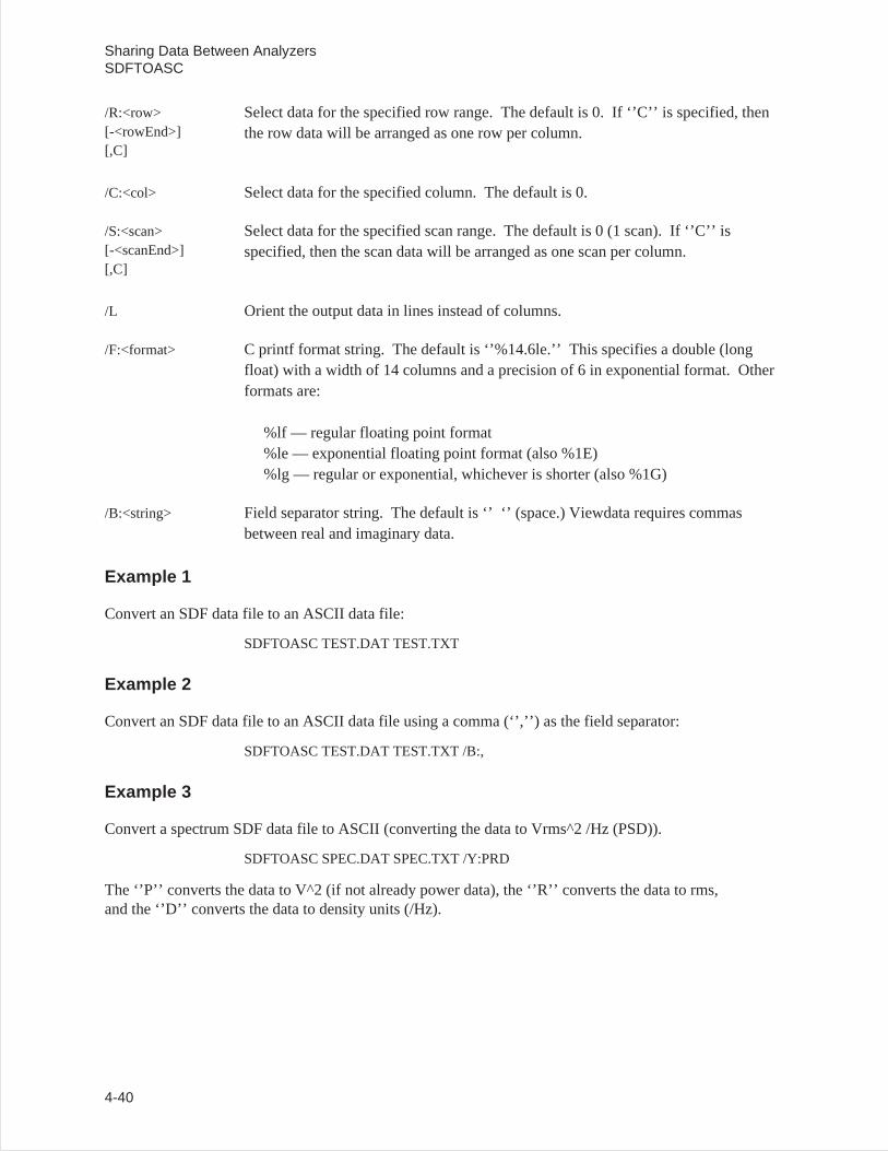
/R:<row>[-<rowEnd>][,C]
Select data for the specified row range. The default is 0. If ‘’C’’ is specified, thenthe row data will be arranged as one row per column.
/C:<col> Select data for the specified column. The default is 0.
/S:<scan>[-<scanEnd>][,C]
Select data for the specified scan range. The default is 0 (1 scan). If ‘’C’’ isspecified, then the scan data will be arranged as one scan per column.
/L Orient the output data in lines instead of columns.
/F:<format> C printf format string. The default is ‘’%14.6le.’’ This specifies a double (longfloat) with a width of 14 columns and a precision of 6 in exponential format. Otherformats are:
%lf — regular floating point format%le — exponential floating point format (also %1E)%lg — regular or exponential, whichever is shorter (also %1G)
/B:<string> Field separator string. The default is ‘’ ‘’ (space.) Viewdata requires commasbetween real and imaginary data.
Example 1
Convert an SDF data file to an ASCII data file:
SDFTOASC TEST.DAT TEST.TXT
Example 2
Convert an SDF data file to an ASCII data file using a comma (‘’,’’) as the field separator:
SDFTOASC TEST.DAT TEST.TXT /B:,
Example 3
Convert a spectrum SDF data file to ASCII (converting the data to Vrms^2 /Hz (PSD)).
SDFTOASC SPEC.DAT SPEC.TXT /Y:PRD
The ‘’P’’ converts the data to V^2 (if not already power data), the ‘’R’’ converts the data to rms,and the ‘’D’’ converts the data to density units (/Hz).
Sharing Data Between AnalyzersSDFTOASC
4-40
Example 4
Convert the complex data to dB, phase (instead of the default real, imaginary), and phase isin radians.
SDFTOASC FRF.DAT FRF.TXT /T:D,P /Y:A
Example 5
Convert a waterfall to a format which a spreadsheet can read in as 1 column per spectrum.
SDFTOASC WFAL.DAT WFAL.TXT /S:0−1000,C
If the ending scan that is selected is too large for the waterfall, then the ending scan is set to the last scanin the waterfall. If the /L option is specified, then each spectrum is in a row (line) rather than in a column.
Example 6
Convert a sound pressure spectrum to dBSPL.
SDFTOASC NOISE.DAT NOISE.TXT /T:D /Y:R /G:20E−6
The units of the NOISE.DAT file are Pascals, so the /T:D option converts to dB, and the /G:20E−6 optionsets the dB reference to 20 micro-Pascals.
Sharing Data Between AnalyzersSDFTOASC
4-41
SDFTOBIN
Convert the source SDF file to the destination binary file. The binary data has the bytes swapped in thesame direction as the rest of the DOS environment.
Syntax SDFTOBIN <sfile> <dfile> [/U] [/O] [/I] [/A] [/X] [/T:<c1>,<c2>] [/Y:<units>][/M:<dBmRef>] [/G:<dBRef>] [/D:<data>] [/R:<row>] [/C:<col>] [/S[:<scan>[−<scanEnd>]]] [/F:<format>]
Options
<sfile> Input SDF file.
<dfile> Output binary file.
/U Show this usage.
/O Overwrite <dfile> if it exists.
/I Info only on <sfile> (that is, measurement results available).
/A All frequency lines.
/X Include X data in the file.
/T:<c1>,<c2> Y coordinate, <c1> or <c2> may be one of the following:B=dBmD=dBS=dB signedM=MagR=RealI=ImagP=PhaseU=Unwrap phase
Default is R,I for complex data; R for real data.
/Y:<units> Y units, one or more of the following:L=Linear,P=Power,D=Density,R=RMS,A=Radians
/M:<dBmRef>] dBm impedance reference. Default is use input impedance from the data file if 1MOhm (else use 50 Ohm).
Sharing Data Between AnalyzersSDFTOBIN
4-42
/G:<dBRef>] Magnitude value used as a reference for dB type of coordinates. If /G with noparameter, then default is 20E−6 (dBSPL).
/D:<data>] Select data for the specified SDF_DATA_HDR (default is 0).
/R:<row>] Select data for the specified row (default is 0).
/C:<col>] Select data for the specified column (default is 0).
/S[:<scan>
[−<scanEnd>]]
Select data for the specified scan range (default is 0).
/F:<format> Binary format, one of the following:F=32-bit floatD=32-bit float
Example
The file TIME.DAT contains 2048 real time points.
SDFTOBIN TIME.DAT TIME.BIN /F:F
This command creates a binary file TIME.BIN with 2048 floats. Since each float is 4 bytes, the file is2048 * 4 = 8192 bytes long.
Sharing Data Between AnalyzersSDFTOBIN
4-43
SDFTOML
Converts data from an SDF format file to the format used in the PC-MATLAB program. The created fileor files have the suffix ‘’.MAT’’ if no destination file is specified.
If the batch file naming convention is used or an output file is specified, then only one measurement resultis translated. The batch file naming convention clears the <sfile> suffix and adds a MAT suffix.
Syntax SDFTOML <sfile> [/U] [/O] [/I] [/A] [/R] [/X] [/Q] [/B] [/D:<data>] [/R:<row>] [/C:<col>][/S:<scans>] [/Y:<units>]
Options
<sfile> Input SDF file name.
/U Show help (usage information) for this program.
/O Overwrites <PC-MATLAB file> if it exists.
/I Show information only on <sfile>, including data result number, result name, thenumber of rows, columns, scans available, the number of data points, whether thedata is real or complex, and type of X spacing between data points.
/A Convert all frequency lines (normally the lines likely to be affected by aliasing arenot converted).
/R Output the PC-MATLAB file matrices in a row instead of a column.
/X Output the X-axis data points.
/Q Query for partial conversion.
For information on naming conventions, refer to ‘’Naming Conventions for Matrix Files’’, ‘’NamingConventions for Y-axis Variables’’ and ‘’Naming Conventions for X-axis Variables’’ under SDFTOMX.
/B Use batch file naming convention (see appendix C).
/D:<data> Extract data only for the specified data header (default all).
/R:<row> Extract data only for the specified data row (default all rows).
/C:<col> Extract data only for the specified data column (default all columns).
Sharing Data Between AnalyzersSDFTOML
4-44
/S:<scans> Extract data only for the specified data scans (default all scans). For example: /S:0means scan 0 only, /S:0-4 means scans 0 through 4.
/Y:<units> Y units, one or more of the following:L=Linear, P=Power, D=Density, R=RMS
See the batch files ‘’60_ML.BAT’’ and ‘’63_ML.BAT’’ in appendix C.
Example
Convert a spectrum SDF data file to PC-Mathlab file. (converting data to Vrms^2/Hz (PsD))
SDFTOML SPEC.DAT /Y:PRD
The ‘’P’’ converts the data to V^2 (if not already power data), the ‘’R’’ converts the data to rms, and the‘’D’’ converts the data to density units (/Hz).
Sharing Data Between AnalyzersSDFTOML
4-45
SDFTOMX
Converts data from the SDF format to the format used in the MATRIXx program. The created file orfiles have the suffix ‘’.MAT’’ if no destination file is specified.
If the batch file naming convention is used or an output file is specified, then only one measurement resultis translated. The batch file naming convention clears the <sfile> suffix and adds a MAT suffix.
Syntax SDFTOMX <sfile> [dfile] [/U] [/O] [/I] [/A] [/R] [/X] [/Q] [/B] [/D:<data>] [/R:<row>][/C:<col>] [/S:<scans>] [/Y:<units>]
Options
<sfile> Input SDF file.
[dfile] Optional output MATRIXx file.
/U Show help (usage information) for this program.
/O Overwrite <MATRIXx file> if it exists.
/I Show information only on <sfile>, including data result number, result name, thenumber of rows, columns, scans available, the number of data points, whether thedata is real or complex, and type of X spacing between data points.
/A Convert all frequency lines (normally the lines likely to be affected by aliasing arenot converted).
/R Output the MATRIXx file matrices in a row instead of a column.
/X Output the X-axis data points.
/Q Query for partial conversion.
/B Use batch file naming convention (see appendix C).
/D:<data> Extract data only for the specified data header (default all).
/R:<row> Extract data only for the specified data row (default all rows).
/C:<col> Extract data only for the specified data column (default all columns).
Sharing Data Between AnalyzersSDFTOMX
4-46

/S:<scans> Extract data only for the specified data scans (default all scans). For example: /S:0means scan 0 only, /S:0-4 means scans 0 through 4.
/Y:<units> Y units, one or more of the following:L=Linear, P=Power, D=Density, R=RMS
See the batch files ‘’60_MX.BAT’’ and ‘’63_MX.BAT’’ in appendix C.
Example
Convert a spectrum SDF data file to a MATRIXx file (converting data to Vrms^2/Hz (PSD)).
SDFTOMX SPEC.DAT /Y:PRD
The ‘’P’’ converts the data to V^2 (if not already power data), the ‘’R’’ converts the data to rms, and the‘’D’’ converts the data to density units (/Hz).
Sharing Data Between AnalyzersSDFTOMX
4-47
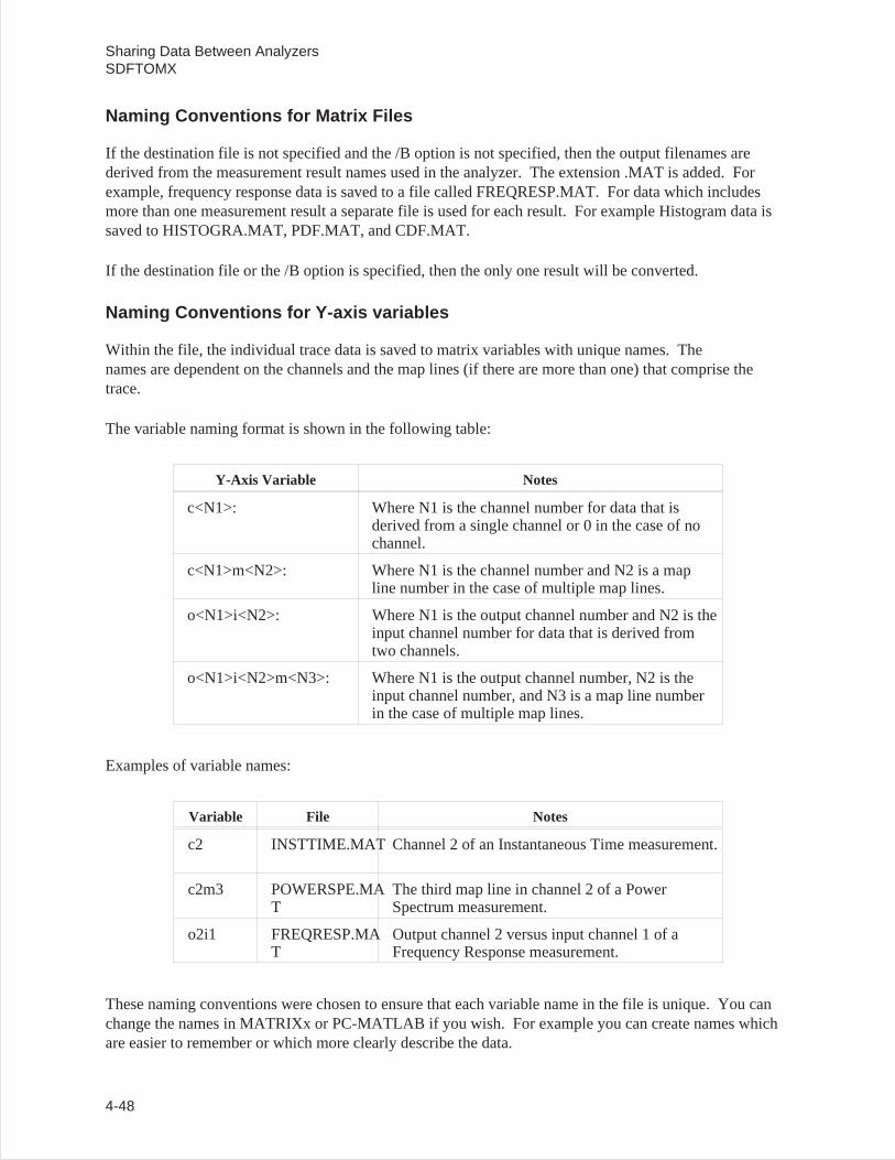
Naming Conventions for Matrix Files
If the destination file is not specified and the /B option is not specified, then the output filenames arederived from the measurement result names used in the analyzer. The extension .MAT is added. Forexample, frequency response data is saved to a file called FREQRESP.MAT. For data which includesmore than one measurement result a separate file is used for each result. For example Histogram data issaved to HISTOGRA.MAT, PDF.MAT, and CDF.MAT.
If the destination file or the /B option is specified, then the only one result will be converted.
Naming Conventions for Y-axis variables
Within the file, the individual trace data is saved to matrix variables with unique names. Thenames are dependent on the channels and the map lines (if there are more than one) that comprise thetrace.
The variable naming format is shown in the following table:
Y-Axis Variable Notes
c<N1>: Where N1 is the channel number for data that isderived from a single channel or 0 in the case of nochannel.
c<N1>m<N2>: Where N1 is the channel number and N2 is a mapline number in the case of multiple map lines.
o<N1>i<N2>: Where N1 is the output channel number and N2 is theinput channel number for data that is derived fromtwo channels.
o<N1>i<N2>m<N3>: Where N1 is the output channel number, N2 is theinput channel number, and N3 is a map line numberin the case of multiple map lines.
Examples of variable names:
Variable File Notes
c2 INSTTIME.MAT Channel 2 of an Instantaneous Time measurement.
c2m3 POWERSPE.MAT
The third map line in channel 2 of a PowerSpectrum measurement.
o2i1 FREQRESP.MAT
Output channel 2 versus input channel 1 of aFrequency Response measurement.
These naming conventions were chosen to ensure that each variable name in the file is unique. You canchange the names in MATRIXx or PC-MATLAB if you wish. For example you can create names whichare easier to remember or which more clearly describe the data.
Sharing Data Between AnalyzersSDFTOMX
4-48
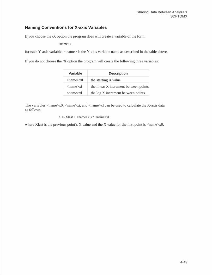
Naming Conventions for X-axis Variables
If you choose the /X option the program does will create a variable of the form:
<name>x
for each Y-axis variable. <name> is the Y-axis variable name as described in the table above.
If you do not choose the /X option the program will create the following three variables:
Variable Description
<name>x0 the starting X value
<name>xi the linear X increment between points
<name>xl the log X increment between points
The variables <name>x0, <name>xi, and <name>xl can be used to calculate the X-axis dataas follows:
X = (Xlast + <name>xi) * <name>xl
where Xlast is the previous point’s X value and the X value for the first point is <name>x0.
Sharing Data Between AnalyzersSDFTOMX
4-49
SDFTOSDF
Extracts a subset of results from an SDF file <sfile> and creates another SDF file <dfile>. The type ofspacing and number of points for the results may be modified through resampling using polynomial orspline interpolation. (See chapter 2.)
Syntax SDFTOSDF <sfile> <dfile> [/U] [/O] [/I] [/D:<data>] [/S:<scans>] [/R:<row>] [/C:<col>][/E:<pts>] [/P:<pts>] [/L:<pts>] [/T:<type>] [/N:<pts>] [/X:<first>,<last>][/B:<rec>] [/G:<gap>] [/A:<add>] [/F:<form>,<data>] [/M:[cfile] [,<comSz>]] [/V][/Q:[uniq]]
Options
<sfile> Source path and file name for SDF file.
<dfile> Destination path and file for SDF file.
/U Show help (usage information) for this command.
/O Overwrites <dfile> if it exists.
/I Show information only on <sfile>, including data result number, result name, thenumber of rows, columns, scans available, the number of data points, and type of Xspacing between data points.
/D:<data> Extract data only for the specified data result (see figure 2-1). If not specified, thenall results in <sfile> will be selected.
/S:<scans> Extract data only for the specified scan (see figure 2-3). If not specified, then allscans in <sfile> will be selected. Either a single scan (e.g. /S:0 for scan 0) or arange of scans (e.g. /S:0-4 for scans 0 thru 4) may be selected.
/R:<row> Extract data only for the specified row (see figure 2-2). If not specified, then allrows in <sfile> will be selected.
/C:<col> Select column within result. If not specified, then all columns in <sfile> willbe selected.
/E:<pts> Interpolate to the specified number of lin/log evenly spaced points. The X data isscanned to determine if the data is approximately linear or log spaced. If thenumber of points is not specified, then the original number of points in the dataresult is maintained. This is useful if you want to do math or curve fit swept sinedata, or examine results with a large number of lines of resolution on an analyzerthat is limited to fewer lines.
Sharing Data Between AnalyzersSDFTOSDF
4-50
/P:<pts> Interpolate to the specified number of linear spaced points. If the number of pointsis not specified, then the original number of points in the data result is maintained.This is useful if you want to do math or curve fit swept sine data, or examine resultswith a large number of lines of resolution on analyzer that is limited to fewer lines.
/L:<pts> Interpolate to the specified number of log spaced points. If the number of points isnot specified, then the original number of points in the data result is maintained.This is useful if you want to do math or curve fit swept sine data, or examine resultswith a large number of lines of resolution on analyzer that is limited to fewer lines.
/T:<type> Type of interpolation: S = Spline, P = Polynomial. Default is P.
/N:<pts> Number of points for polynomial interpolation. Range: 2 – 10. Default is 2. Thedefault spacing is linear (polynomial interpolation and 2 points).
/X:<first>,<last>
First and last X value of data (default is all the data). Can specify either or both.
/B:<rec> Bar record from being copied: U = Unique
/G:<gap> Add the specified # of bytes between each SDF record type area
/A:<add> Add the specified # of bytes to each SDF record
/F:<form>,<data>
Convert number format of y data for the specified data header to the formatspecified: S=SHORT16, L=LONG32, F=FLOAT32, D=DOUBLE64,Data # is optional. If the data number is not specified, then all results are converted.
/M:[cfile][,<comSz>]
Add a comment record and/or reserve comSz bytes for a comment record (default is1024)
/V Add scan var duplicate of scan structure
/Q:[uniq] Add the specified unique record: M = Modulation
Sharing Data Between AnalyzersSDFTOSDF
4-51
Example 1
To find out what results are available in an SDF measurement results file from HP 3566A/67A (sweptsine measurement):
SDFTOSDF /I SINEARB.DAT
This will produce a list on the display such as the following.
Data Name Rows Cols Scans Points Complex Space
0 Freq Response 103 Arb1 Nrml Variance 2 103 Arb2 Input Power Ch1 103 Arb3 Output Power Ch2 103 Arb4 Cross Power 103 Arb
This shows 5 results are available (0 thru 4) with 103 arbitrarily spaced points (indicative of swept sinedata). The ‘’Rows’’ field (if present) if usually associated with the # of channels of data available forsingle channel results.
For example, 2 channels of ‘’Normalized Variance’’ measurement results are present. At this time, the‘’Columns’’ field is not used (i.e. always only 1 column of data) by any instrument using SDF as a dataformat. The ‘’Scans’’ field indicates that this data contains Waterfall results from the HP 3566A/67.
To extract and convert the ‘’Normalized Variance’’ channel 2 (row 0 is channel 1, row 1 is channel 2) to401 linear spaced points:
SDFTOSDF SINEARB.DAT SINELIN.DAT /D:1 /R:1 /P:401
Example 2
To extract and convert an FRF from the HP 3563A (801 lines at 0 to 100 kHz) to the HP 35665A (401lines at 0 to 102.4 kHz):
63TOSDF FRF.63 FRF63.DATSDFTOSDF FRF63.DAT FRF665.DAT /P:401 /X:,102400
Sharing Data Between AnalyzersSDFTOSDF
4-52
Discussion
The HP 3566A/67A generally puts all results from a measurement in a single file (see example above).
If no options are selected that specify which data to convert, then all results are selected. This has theeffect of copying everything in the source SDF file <sfile> to the destination SDF file <dfile> (andresampling all data results, if specified). This also has the effect of converting SDF Level 1 files(previously used HP 3566A/67A) to the newer SDF Level 2 files (now used by HP 3566A/67A).
Data is interpolated only if either the /E, /P, or /L option is specified.
The ability to convert arbitrarily space data (Swept Sine measurements) to linear or log space data(through resampling) is necessary when importing data to the HP 3563A.
The ability to change the number of points in a data result (through resampling) is required whenimporting data into an instrument that supports limited data sizes. For example, the HP 35660A supportsup to 1024 complex points in a data result, whereas the HP 3566A/67A can generate results up to 16 Kreal points.
Spline interpolation (/T:S) is useful when converting from a smaller number of points to a much largernumber of points when you want the data to be smoothed. Polynomial interpolation (/T:P) with linear fit(/N:2) or quadratic fit (/N:3) is faster than a spline fit and is useful when converting to nearly the samenumber or fewer points. (Quadratic fit is also good for interpolating to a larger number of points.)
If the data is real, the real part of the data is interpolated. If the data is complex, the magnitude and phaseparts of the data are interpolated separately.
With the /X option, you may specify X values either within the data or outside of the data. If an X valuespecified is outside of the data, the curve is extrapolated to fill in points to the specified X value. For logdata, you must specify X values greater than 0.
Sharing Data Between AnalyzersSDFTOSDF
4-53
SDFYDATA
Modify/print SDF file <sfile> Y data. If [afile] or /Y option is specified then the Y data in the SDF file ismodified, otherwise the data is printed.
Syntax SDFYDATA <sfile> [afile] [/U] [/I] [/D:<data>] [/S:<scan>] [/R:<row>] [/C:<col>][/O:<ofst>[,<unit>]] [/L:<len>[,<unit>]] [/Y:<real>[,<imag>]]
<sfile> SDF file.
[afile] Input ASCII file with numbers.
/U Show this usage.
/I Info only on <sfile> (that is, measurement results available).
/D:<data> Select data only for the specified SDF_DATA_HDR (default is 0).
/S:<scan> Select data only for the specified scan (default is 0).
/R:<row> Select data only for the specified row (default is 0).
/C:<col> Select data only for the specified column (default is 0).
/O:<ofst>[,<unit>]
Offset into the data by <ofst>. <unit> may be R (records), P (points) or S(seconds); default is P.
/L:<len>[,<unit>]
Length of data to change, default is one point. Only used if [afile] is not specified.
/Y:<real>[,<imag>]
Value to change SDF file with. Only used if [afile] is not specified.
Example
Print out 10 mS of data after the 2 seconds of data in a time capture file (CAPT.TIM)
SDFYDATA CAPT.TIM /O:0.01,S /L:2,S
Zero out the same region of data (just printed) in the time capture file.
SDFYDATA CAPT.TIM /O:0.01,S /L:2,S /Y:0
Copy the first 10 mS of data to the second 10 mS of data in a time capture file.
SDFYDATA CAPT.TIM > TEMP /L:0.01,SSDFYDATA CAPT.TIM TEMP /O:0.01,S
Sharing Data Between AnalyzersSDFYDATA
4-54
SETUP63
Converts a binary setup state file from the HP 3563A (or HP 3562A) to an ASCII form (written todestination file). Refer to the HP 3563A or HP 3562A programming manual for descriptions of theindividual fields in the setup state file. HP 3563A/62A setup state files on a LIF file system start with theletters ‘’SE.’’
Syntax SETUP63 <sfile> [dfile] [/U] [/O] [/L:<flag>] [/E:<flag>]
Options
<sfile> Input HP 3563A/62A setup state file name.
[dfile] Optional output ASCII file name. If no file specified, output to display.
/U Show help (usage information) for this program.
/O Overwrite [dfile] if it exists.
/L:<flag> If <flag> is non-zero, put labels on each line. The name of each field will be thefirst 25 characters of each line (approximately as they appear in the HP 3563A orHP 3562AProgramming Manual). The default is on.
/E:<flag> If <flag> is non-zero, expand enumerated types to ASCII names (approximately asthey appear in the HP 3563A or HP 3562AProgramming Manual). The default ison.
Sharing Data Between AnalyzersSETUP63
4-55
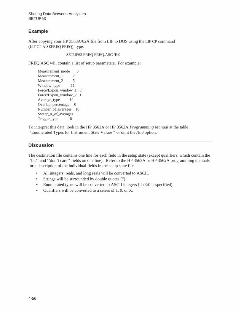
Example
After copying your HP 3563A/62A file from LIF to DOS using theLIF CP command(LIF CP A:SEFREQ FREQ), type:
SETUP63 FREQ FREQ.ASC /E:0
FREQ.ASC will contain a list of setup parameters. For example:
Measurement_mode 0Measurement_1 2Measurement_2 5Window_type 11Force/Expon_window_1 0Force/Expon_window_2 1Average_type 10Overlap_percentage 0Number_of_averages 10Sweep_#_of_averages 1Trigger_type 18
To interpret this data, look in the HP 3563A or HP 3562AProgramming Manualat the table‘’Enumerated Types for Instrument State Values’’ or omit the /E:0 option.
Discussion
The destination file contains one line for each field in the setup state (except qualifiers, which contain the‘’bit’’ and ‘’don’t care’’ fields on one line). Refer to the HP 3563A or HP 3562A programming manualsfor a description of the individual fields in the setup state file.
• All integers, reals, and long reals will be converted to ASCII.• Strings will be surrounded by double quotes (“).• Enumerated types will be converted to ASCII integers (if /E:0 is specified).• Qualifiers will be converted to a series of 1, 0, or X.
Sharing Data Between AnalyzersSETUP63
4-56

SETUP88
Converts a binary setup state file from the HP 3588A to an ASCII form written to a destination file.
Syntax SETUP88 <sfile> [dfile] [/O] [/U] [/M <mfile>] [/L:<flag>] [/E:<flag>]
Options
<sfile> Input HP 3588A setup state path and file name.
[dfile] Optional destination path and file name. If no file is specified, it outputs to thedisplay.
/O Overwrite [dfile] if it already exists.
/U Show help (usage information) for this program.
/M Read HP 3588A math file for additional information.
<mfile> HP 3588A math path and file name.
/L:<flag> If <flag> is non-zero, put labels on each line. The name of each field will be thefirst 25 characters of each line. The default is on.
/E:<flag> If <flag> is non-zero, expand enumerated types to ASCII names. The default is on.
Sharing Data Between AnalyzersSETUP88
4-57
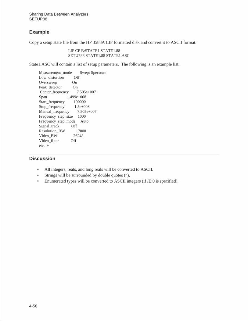
Example
Copy a setup state file from the HP 3588A LIF formatted disk and convert it to ASCII format:
LIF CP B:STATE1 STATE1.88SETUP88 STATE1.88 STATE1.ASC
State1.ASC will contain a list of setup parameters. The following is an example list.
Measurement_mode Swept SpectrumLow_distortion OffOversweep OnPeak_detector OnCenter_frequency 7.505e+007Span 1.499e+008Start_frequency 100000Stop_frequency 1.5e+008Manual_frequency 7.505e+007Frequency_step_size 1000Frequency_step_mode AutoSignal_track OffResolution_BW 17000Video_BW 26248Video_filter Offetc. +
Discussion
• All integers, reals, and long reals will be converted to ASCII.• Strings will be surrounded by double quotes (“).• Enumerated types will be converted to ASCII integers (if /E:0 is specified).
Sharing Data Between AnalyzersSETUP88
4-58
SETUP89
Converts a binary setup state file from the HP 3589A to an ASCII form written to a destination file.
Syntax SETUP89 <sfile> [dfile] [/O] [/U] [/M <mfile>] [/L:<flag>] [/E:<flag>]
Options
<sfile> Input HP 3589A setup state path and file name.
[dfile] Optional destination path and file name. If no file is specified, it outputs to thedisplay.
/O Overwrite [dfile] if it already exists.
/U Show help (usage information) for this program.
/M Read HP 3589A math file for additional information.
<mfile> HP 3589A math path and file name.
/L:<flag> If <flag> is non-zero, put labels on each line. The name of each field will be thefirst 25 characters of each line. The default is on.
/E:<flag> If <flag> is non-zero, expand enumerated types to ASCII names. The default is on.
Sharing Data Between AnalyzersSETUP89
4-59
Example
Copy a setup state file from the HP 3589A LIF formatted disk and convert it to ASCII format:
LIF CP B:STATE1 STATE1.89SETUP89 STATE1.89 STATE1.ASC
State1.ASC will contain a list of setup parameters. The following is an example list.
Measurement_mode Swept SpectrumLow_distortion OffOversweep OffPeak_detector OffCenter_frequency 7.505e+007Span 1.499e+008Start_frequency 100000Stop_frequency 1.5e+008Manual_frequency 0Frequency_step_size 1000Frequency_step_mode AutoSignal_track OffResolution_BW 290Video_BW 26248Video_filter Offetc. +
Discussion
• All integers, reals, and long reals will be converted to ASCII.• Strings will be surrounded by double quotes (“).• Enumerated types will be converted to ASCII integers (if /E:0 is specified).
Sharing Data Between AnalyzersSETUP89
4-60
SOFTCOPY
Transfers data from the HP-IB (IEEE-488 bus) to a file. Allows your PC to emulate a hardcopy devicesuch as a plotter or printer, so screen dumps from various instruments can be captured. Hardcopy fromHP-IB Instrument can be routed to an RS-232 printer or plotter by specifying PRN for the output file.Requires an HP 82335A interface card, or National Instrument GPIB-PC interface card.
Syntax SOFTCOPY [dfile] [/U] [/O] [/L] [/A:<addr>]
Options
[dfile] Output file.
/U Show this usage
/O Overwrite [dfile] if it exists
/L Longer end-of-data timeout (30 sec). Default is 3 sec.
/A:<addr> Set primary IEEE 488 bus address. Default is 5, use 31 to emulate a listen-onlyplotter or printer.
Example 1
To capture a plot from a HP 3562A Dynamic Signal Analyzer in a file, connect the analyzer to the PC’sHP-IB card. Then setup the analyzer “HP-IB fctn” as “system controller”, and set “plot address” to 5.Start softcopy with the following command
SOFTCOPY APLOT.PLT /A:5
Then press “start plot” on the analyzer. When the plot is done, the file can be inserted into a MicrosoftWord for Windows document.
Example 2
To send a screen dump from an HP 54502A Oscilloscope to a DeskJet printer, connect the Oscilloscopeto the PC’s HP-IB card. Connect the printer to the PC’s parallel interface. Setup the Oscilloscope’s“Utility / HP-IB” as “talk only”. Start softcopy with the following command:
SOFTCOPY PRN /O /A:31
Then press the “hardcopy” button on the Oscilloscope.
Sharing Data Between AnalyzersSOFTCOPY
4-61
SYNTH63
Converts a binary synthesis file from the HP 3563A or HP 3562A to an ASCII file, a PC-MATLAB file,or a MATRIXx file. HP 3563A/62A synthesis files on a LIF file system start with the letters ‘’ST’’(Z-domain ‘’ZT’’); curve fit files start with the letters ‘’CV’’ (Z-domain ‘’ZF’’).
Syntax SYNTH63 <sfile> <dfile> [/U] [/O] [/L] [/M] [/R]
Options
<sfile> Input HP 3563A/62A synthesis file name.
<dfile> Output file name.
/U Show help (usage information) for this program.
/O Overwrites <dfile> if it exists.
/L Create MATLAB File (a binary file).
/M Create MATRIXx File (an ASCII file).
/R Output MATLAB or MATRIXx file matrices in a row instead of a column.
If neither /L nor /M option is specified, then an ASCII file is created.
Example 1
Convert your file to a PC-MATLAB file. Note that PC-MATLAB searches for a file with the suffix‘’.MAT’’ if no other suffix is specified. See appendix for more information on loading a file intoPC-MATLAB.
SYNTH63 FREQ C:FREQ.MAT /L
Example 2
Convert your file to MATRIXx row format:
SYNTH63 FREQ A:\APPLIC\FREQ.MAT /M /R
Example 3
Output data to an ASCII file:
SYNTH63 FREQ FREQ.ASC
Sharing Data Between AnalyzersSYNTH63
4-62
Discussion
A synthesis table contains a maximum of 22 poles/zeros, poles/residues, or numerators/denominators(polynomial). It also contains the time delay, system gain, and either scale frequency (s-domain) orsample frequency and z power sign (z-domain).
The first 4 lines of the ASCII file contain the time delay, system gain, scale or sample frequency, and zpower sign, respectively. The next line contains the # of poles (or numerators) followed by the # of zeros(or residues or denominators). Each of the following lines contain a complex pole (2 fields) followed bya complex zero (2 fields). This is repeated for all the poles and zeros in the synthesis table. If there arefewer zeros than poles, then the extra zeros contain the value 0.0, 0.0 (and vice versa). (MATLAB andMATRIXx files are not zero filled.)
Both the MATLAB and MATRIXx files contain the following matrix variables:
TimeDelay Time delay (in seconds)
SysGain System gain
SynthFreq Scale frequency (Hz) if s-domain tableSample frequency (Hz) if z-domain table
PoleData Vector of complex poles (if pole/zero or pole/residue table)
NumerData Vector of complex numerators (if polynomial table)
ZeroData Vector of complex zeros (if pole/zero table)
ResData Vector of complex residues (if pole/residue table)
DenomData Vector of complex denominators (if polynomial table)
Zpower 1 if negative z powers, 0 if positive z powers. (Only useful for z-domain table.)
Sharing Data Between AnalyzersSYNTH63
4-63
X32TOBIN
Convert data from Intel Hex-32 source data file and put the results in the destination binary file.
Syntax X32TOBIN <sfile> <dfile> [/U] [/O]
Options
<sfile> Input Hex-32 data file.
<dfile> Output binary file.
/U Show help (usage information) for this program.
/O Overwrite <dfile> if it exists.
Example
Convert an Intel Hex-32 file (FREQ.X32) to a binary data file (FREQ.BIN).
X32TOBIN FREQ.X32 FREQ.BIN
Sharing Data Between AnalyzersX32TOBIN
4-64
Error Messages
Cannot openoutput file
This error is generated if the output file cannot be opened with writepermissions. Check for a valid path/file name. Also, check to see if thefile is write protected.
Cannot openinput file
This error is generated if the input file cannot be opened with readpermissions. Check for a valid path/file name. Also, check to see if thefile is read protected.
Out of Memory 63TOSDF can generate this error if it cannot allocate enough memory tofully contain the data portion of the file specified. Check to see if theinput file is a valid HP 3562A/3563A data file. If it is not, then garbagein, garbage out (or out of memory). If it is a valid file, then you need tofree up some memory.
Unknown Option ‘x’ This error may be generated by all the commands. Check your options.Typing the command with /U will list the valid options. Options are notcase sensitive and not order dependant.
Sharing Data Between AnalyzersError Messages
4-65

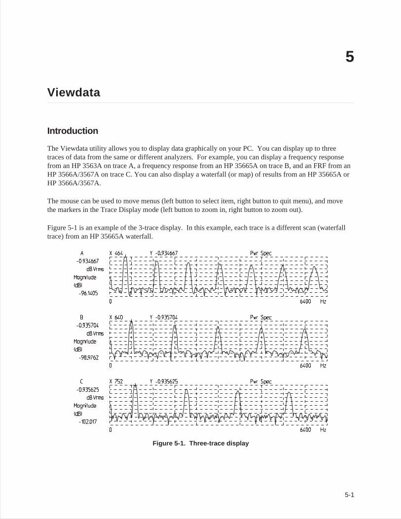
5
Viewdata
Introduction
The Viewdata utility allows you to display data graphically on your PC. You can display up to threetraces of data from the same or different analyzers. For example, you can display a frequency responsefrom an HP 3563A on trace A, a frequency response from an HP 35665A on trace B, and an FRF from anHP 3566A/3567A on trace C. You can also display a waterfall (or map) of results from an HP 35665A orHP 3566A/3567A.
The mouse can be used to move menus (left button to select item, right button to quit menu), and movethe markers in the Trace Display mode (left button to zoom in, right button to zoom out).
Figure 5-1 is an example of the 3-trace display. In this example, each trace is a different scan (waterfalltrace) from an HP 35665A waterfall.
Figure 5-1. Three-trace display
5-1
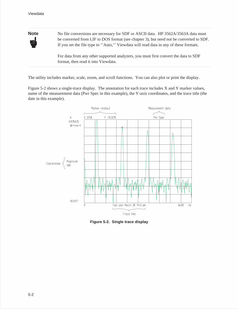
Note No file conversions are necessary for SDF or ASCII data. HP 3562A/3563A data mustbe converted from LIF to DOS format (see chapter 3), but need not be converted to SDF.If you set the file type to ‘’Auto,’’ Viewdata will read data in any of these formats.
For data from any other supported analyzers, you must first convert the data to SDFformat, then read it into Viewdata.
The utility includes marker, scale, zoom, and scroll functions. You can also plot or print the display.
Figure 5-2 shows a single-trace display. The annotation for each trace includes X and Y marker values,name of the measurement data (Pwr Spec in this example), the Y-axis coordinates, and the trace title (thedate in this example).
Figure 5-2. Single trace display
Viewdata
5-2
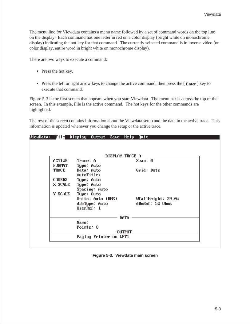
The menu line for Viewdata contains a menu name followed by a set of command words on the top lineon the display. Each command has one letter in red on a color display (bright white on monochromedisplay) indicating the hot key for that command. The currently selected command is in inverse video (oncolor display, entire word in bright white on monochrome display).
There are two ways to execute a command:
• Press the hot key.
• Press the left or right arrow keys to change the active command, then press the [Enter ] key toexecute that command.
Figure 5-3 is the first screen that appears when you start Viewdata. The menu bar is across the top of thescreen. In this example, File is the active command. The hot keys for the other commands arehighlighted.
The rest of the screen contains information about the Viewdata setup and the data in the active trace. Thisinformation is updated whenever you change the setup or the active trace.
Figure 5-3. Viewdata main screen
Viewdata
5-3
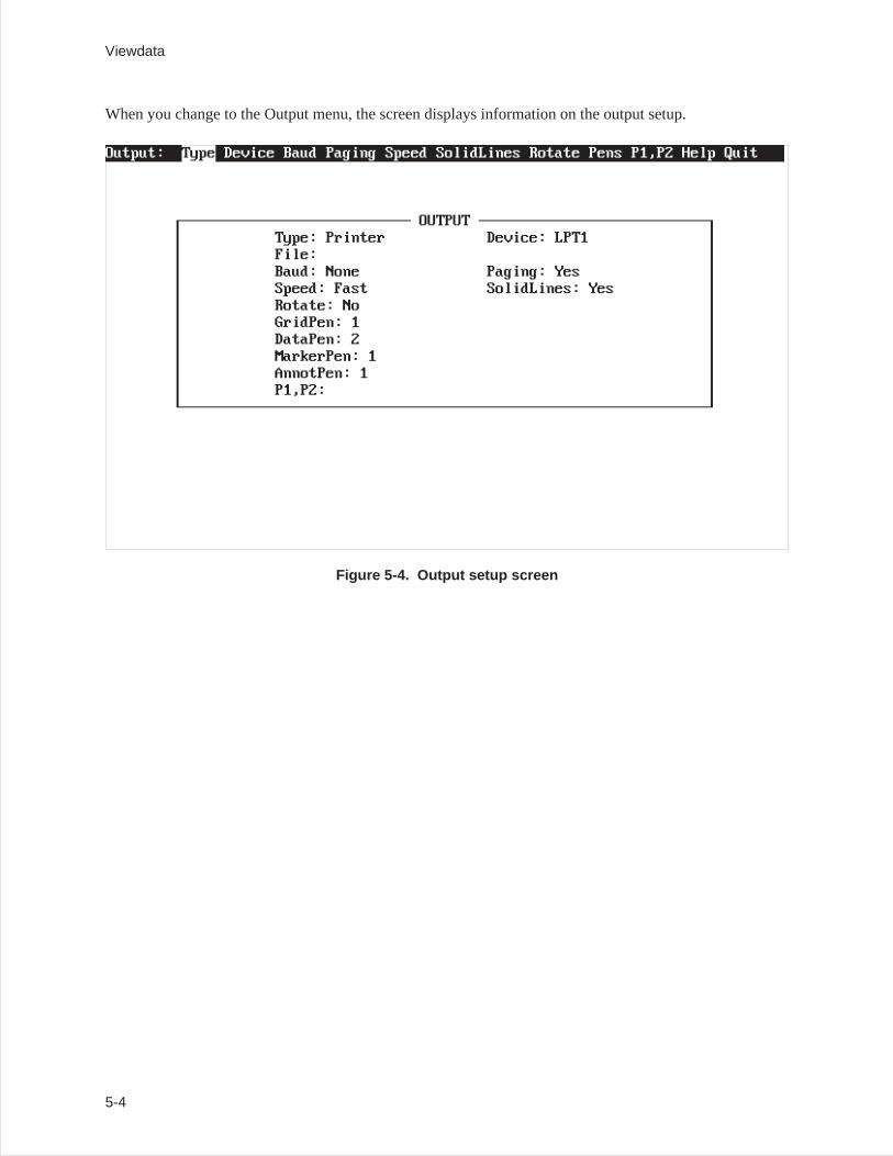
When you change to the Output menu, the screen displays information on the output setup.
Figure 5-4. Output setup screen
Viewdata
5-4
VIEWDATA
Syntax
VIEWDATA [/D:<data>] [/S:<scans>] [/R:<row>] [<fileA>] [<fileB>] [<fileC>] [/U][/T:<title>] [/K:<keyFile>] [/E:<echoFile>] [/P] [/P:<plotfile>] [/I:<iniFile>][/A:<ascFile>] [/O:<ovlFile>] [/W:<wideCnt>] [/H:<highCnt>][/N:<pltNum>] [/M:<time>]
/D:<data> Specify data result in file (default is result 0 if /P)
/R:<row> Specify row in file (default is row 0 if /P)
/S:<scans> Specify scan in file (default is scan 0 if /P). Can specify a range separated by ‘’-’’(for example, /S:0-5).
<fileA> Data file to read into Trace A.
<fileB> Data file to read into Trace B.
<fileC> Data file to read into Trace C.
/U Show help (usage information) for this command.
/T:<title> Set the trace title (up to 30 characters) to be displayed on the X-axis of the data. Ifthe title is empty, the measurement title from the data file is used. If you want touse a space in the trace title, surround the title with quotes (for example, “TraceTitle”).
/K:<keyFile> Specify file from which to read key presses (redirect input).
/E:<echoFile> Specify file to echo (record) key presses (useful for playing back keys using the /Koption).
/P Plot/print data and then exit program.
/P:<plotFile> Plot/print data to specified file and then exit program. (See batch files‘’60_PLOT.BAT’’ and ‘’63_PLOT.BAT’’ in appendix C.)
/A:<ascFile> Dump ASCII data to specified file and then exit program.
/I:<iniFile> Specify configuration file to read instead of VIEWDATA.INI. (See ‘’Config’’ inthe Save menu.)
/O:<ovlFile> Specify file which contains HP-GL text/graphics to overlay upon the trace.
/W:<wideCnt> The number of plots per page wide.
Viewdata
5-5
/H:<highCnt> The number of plots per page high.
/N:<pltNum> Which plot this is (relative to /W and /H). If not set when /W or /H used, then theplot number is automatically incremented & stored in ‘VIEWDATA.INX’ for thenext plot.
/M:<time> Display trace, wait <time> seconds, and exit program.
Example 1
To start Viewdata, type:
VIEWDATA [ Enter ]
Example 2
To start Viewdata and display a particular file, type:
VIEWDATA <filename> [ Enter ]
Example 3
To start Viewdata and display one file in trace A and another file in trace B, type:
VIEWDATA <filename1> <filename2> [Enter ]
Example 4
To start Viewdata and display one file in trace A, another file in trace B, and a third file in trace C, type:
VIEWDATA <filename1> <filename2> <filename3> [Enter ]
Example 5
To plot 3 traces side-by-side (wide) and 2 traces deep (high) for a group of files, type:
REPEAT viewdata /w:3 /h:2 *.dat /p [Enter ]
With the /W, /H, and /N options to VIEWDATA, you could specify where the current trace will beplotted on a page.
Viewdata
5-6
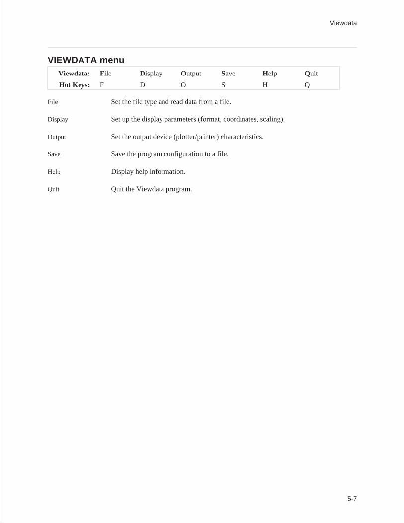
VIEWDATA menuViewdata: File Display Output Save Help Quit
Hot Keys: F D O S H Q
File Set the file type and read data from a file.
Display Set up the display parameters (format, coordinates, scaling).
Output Set the output device (plotter/printer) characteristics.
Save Save the program configuration to a file.
Help Display help information.
Quit Quit the Viewdata program.
Viewdata
5-7
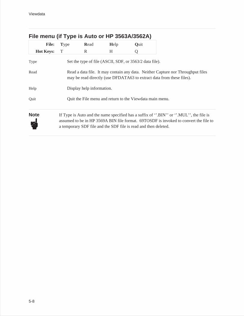
File menu (if Type is Auto or HP 3563A/3562A)File: Type Read Help Quit
Hot Keys: T R H Q
Type Set the type of file (ASCII, SDF, or 3563/2 data file).
Read Read a data file. It may contain any data. Neither Capture nor Throughput filesmay be read directly (use DFDATA63 to extract data from these files).
Help Display help information.
Quit Quit the File menu and return to the Viewdata main menu.
Note If Type is Auto and the name specified has a suffix of ‘’.BIN’’ or ‘’.MUL’’, the file isassumed to be in HP 3569A BIN file format. 69TOSDF is invoked to convert the file toa temporary SDF file and the SDF file is read and then deleted.
Viewdata
5-8
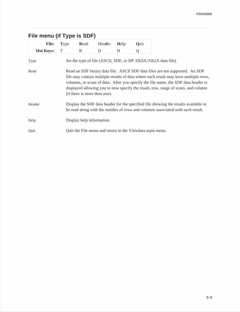
File menu (if Type is SDF)File: Type Read Header Help Quit
Hot Keys: T R D H Q
Type Set the type of file (ASCII, SDF, or HP 3563A/3562A data file).
Read Read an SDF binary data file. ASCII SDF data files are not supported. An SDFfile may contain multiple results of data where each result may have multiple rows,columns, or scans of data. After you specify the file name, the SDF data header isdisplayed allowing you to now specify the result, row, range of scans, and column(if there is more than one).
Header Display the SDF data header for the specified file showing the results available tobe read along with the number of rows and columns associated with each result.
Help Display help information.
Quit Quit the File menu and return to the Viewdata main menu.
Viewdata
5-9
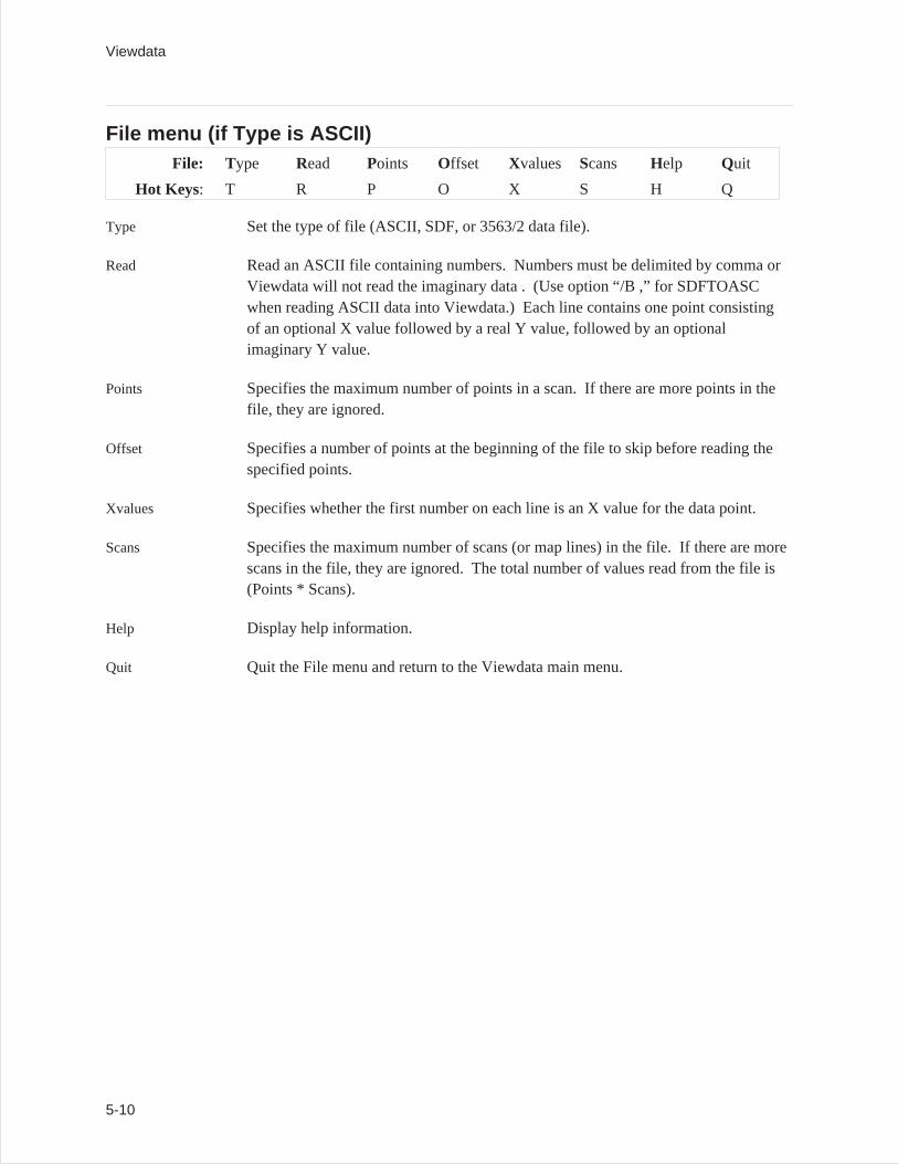
File menu (if Type is ASCII)File: Type Read Points Offset Xvalues Scans Help Quit
Hot Keys: T R P O X S H Q
Type Set the type of file (ASCII, SDF, or 3563/2 data file).
Read Read an ASCII file containing numbers. Numbers must be delimited by comma orViewdata will not read the imaginary data . (Use option “/B ,” for SDFTOASCwhen reading ASCII data into Viewdata.) Each line contains one point consistingof an optional X value followed by a real Y value, followed by an optionalimaginary Y value.
Points Specifies the maximum number of points in a scan. If there are more points in thefile, they are ignored.
Offset Specifies a number of points at the beginning of the file to skip before reading thespecified points.
Xvalues Specifies whether the first number on each line is an X value for the data point.
Scans Specifies the maximum number of scans (or map lines) in the file. If there are morescans in the file, they are ignored. The total number of values read from the file is(Points * Scans).
Help Display help information.
Quit Quit the File menu and return to the Viewdata main menu.
Viewdata
5-10
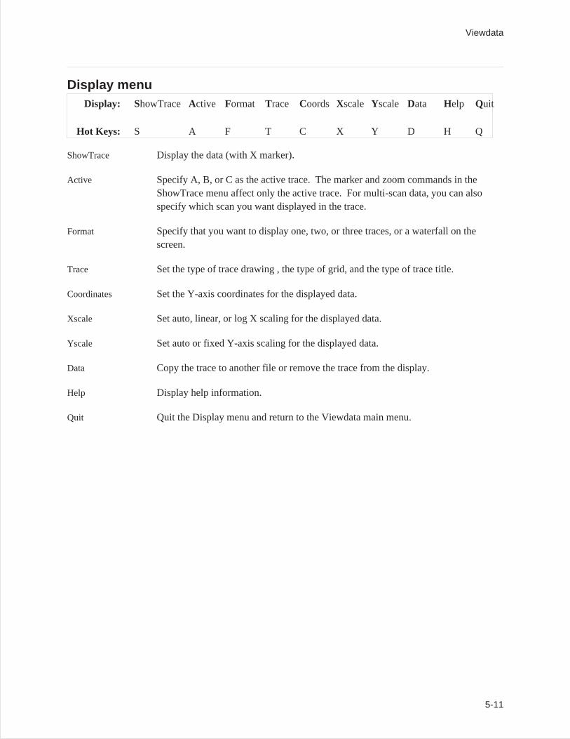
Display menuDisplay: ShowTrace Active Format Trace Coords Xscale Yscale Data Help Quit
Hot Keys: S A F T C X Y D H Q
ShowTrace Display the data (with X marker).
Active Specify A, B, or C as the active trace. The marker and zoom commands in theShowTrace menu affect only the active trace. For multi-scan data, you can alsospecify which scan you want displayed in the trace.
Format Specify that you want to display one, two, or three traces, or a waterfall on thescreen.
Trace Set the type of trace drawing , the type of grid, and the type of trace title.
Coordinates Set the Y-axis coordinates for the displayed data.
Xscale Set auto, linear, or log X scaling for the displayed data.
Yscale Set auto or fixed Y-axis scaling for the displayed data.
Data Copy the trace to another file or remove the trace from the display.
Help Display help information.
Quit Quit the Display menu and return to the Viewdata main menu.
Viewdata
5-11
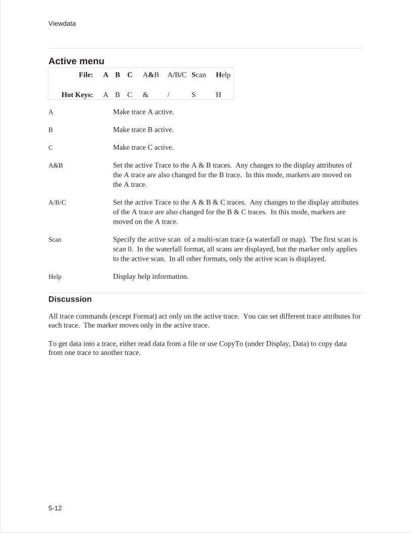
Active menuFile: A B C A& B A/B/C Scan Help
Hot Keys: A B C & / S H
A Make trace A active.
B Make trace B active.
C Make trace C active.
A&B Set the active Trace to the A & B traces. Any changes to the display attributes ofthe A trace are also changed for the B trace. In this mode, markers are moved onthe A trace.
A/B/C Set the active Trace to the A & B & C traces. Any changes to the display attributesof the A trace are also changed for the B & C traces. In this mode, markers aremoved on the A trace.
Scan Specify the active scan of a multi-scan trace (a waterfall or map). The first scan isscan 0. In the waterfall format, all scans are displayed, but the marker only appliesto the active scan. In all other formats, only the active scan is displayed.
Help Display help information.
Discussion
All trace commands (except Format) act only on the active trace. You can set different trace attributes foreach trace. The marker moves only in the active trace.
To get data into a trace, either read data from a file or use CopyTo (under Display, Data) to copy datafrom one trace to another trace.
Viewdata
5-12
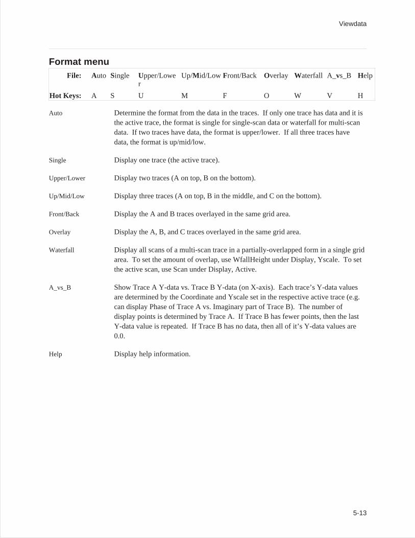
Format menuFile: Auto Single Upper/Lowe
rUp/M id/Low Front/Back Overlay Waterfall A_vs_B Help
Hot Keys: A S U M F O W V H
Auto Determine the format from the data in the traces. If only one trace has data and it isthe active trace, the format is single for single-scan data or waterfall for multi-scandata. If two traces have data, the format is upper/lower. If all three traces havedata, the format is up/mid/low.
Single Display one trace (the active trace).
Upper/Lower Display two traces (A on top, B on the bottom).
Up/Mid/Low Display three traces (A on top, B in the middle, and C on the bottom).
Front/Back Display the A and B traces overlayed in the same grid area.
Overlay Display the A, B, and C traces overlayed in the same grid area.
Waterfall Display all scans of a multi-scan trace in a partially-overlapped form in a single gridarea. To set the amount of overlap, use WfallHeight under Display, Yscale. To setthe active scan, use Scan under Display, Active.
A_vs_B Show Trace A Y-data vs. Trace B Y-data (on X-axis). Each trace’s Y-data valuesare determined by the Coordinate and Yscale set in the respective active trace (e.g.can display Phase of Trace A vs. Imaginary part of Trace B). The number ofdisplay points is determined by Trace A. If Trace B has fewer points, then the lastY-data value is repeated. If Trace B has no data, then all of it’s Y-data values are0.0.
Help Display help information.
Viewdata
5-13
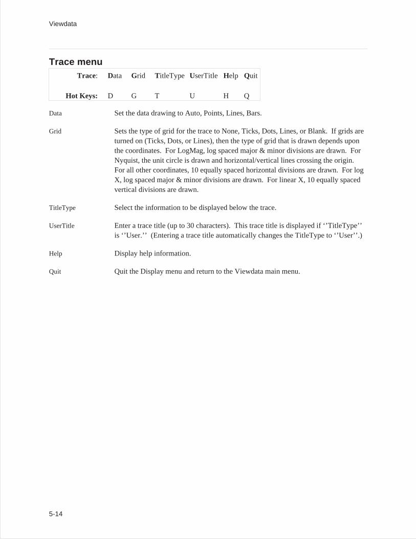
Trace menuTrace: Data Grid TitleType UserTitle Help Quit
Hot Keys: D G T U H Q
Data Set the data drawing to Auto, Points, Lines, Bars.
Grid Sets the type of grid for the trace to None, Ticks, Dots, Lines, or Blank. If grids areturned on (Ticks, Dots, or Lines), then the type of grid that is drawn depends uponthe coordinates. For LogMag, log spaced major & minor divisions are drawn. ForNyquist, the unit circle is drawn and horizontal/vertical lines crossing the origin.For all other coordinates, 10 equally spaced horizontal divisions are drawn. For logX, log spaced major & minor divisions are drawn. For linear X, 10 equally spacedvertical divisions are drawn.
TitleType Select the information to be displayed below the trace.
UserTitle Enter a trace title (up to 30 characters). This trace title is displayed if ‘’TitleType’’is ‘’User.’’ (Entering a trace title automatically changes the TitleType to ‘’User’’.)
Help Display help information.
Quit Quit the Display menu and return to the Viewdata main menu.
Viewdata
5-14
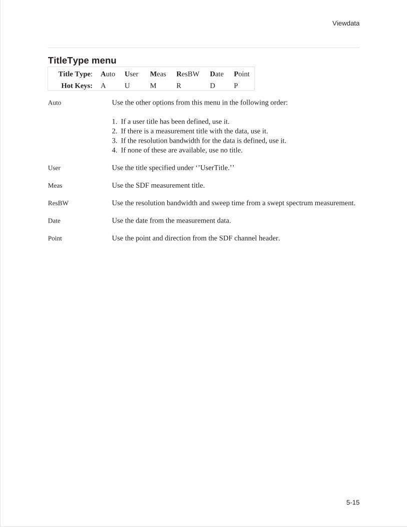
TitleType menuTitle Type: Auto User Meas ResBW Date Point
Hot Keys: A U M R D P
Auto Use the other options from this menu in the following order:
1. If a user title has been defined, use it.2. If there is a measurement title with the data, use it.3. If the resolution bandwidth for the data is defined, use it.4. If none of these are available, use no title.
User Use the title specified under ‘’UserTitle.’’
Meas Use the SDF measurement title.
ResBW Use the resolution bandwidth and sweep time from a swept spectrum measurement.
Date Use the date from the measurement data.
Point Use the point and direction from the SDF channel header.
Viewdata
5-15
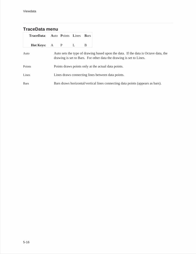
TraceData menuTraceData: Auto Points L ines Bars
Hot Keys: A P L B
Auto Auto sets the type of drawing based upon the data. If the data is Octave data, thedrawing is set to Bars. For other data the drawing is set to Lines.
Points Points draws points only at the actual data points.
Lines Lines draws connecting lines between data points.
Bars Bars draws horizontal/vertical lines connecting data points (appears as bars).
Viewdata
5-16
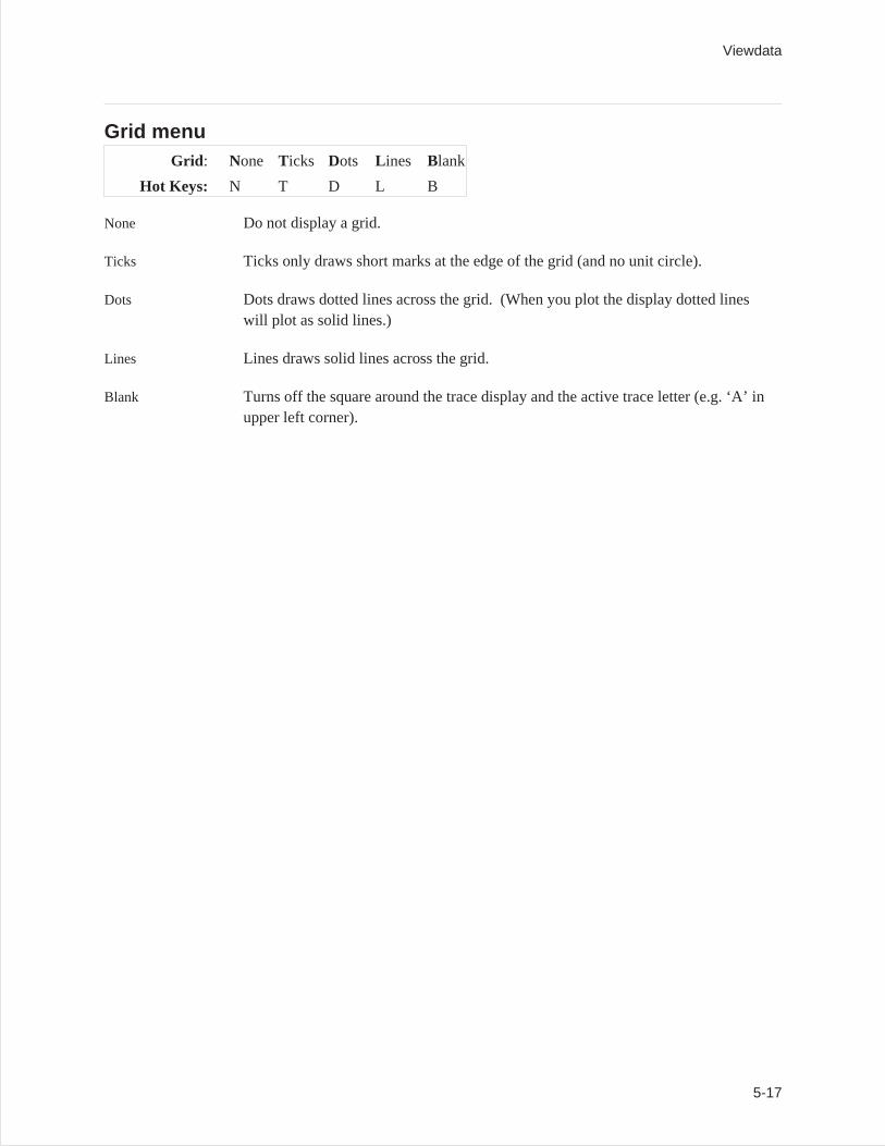
Grid menuGrid : None Ticks Dots L ines Blank
Hot Keys: N T D L B
None Do not display a grid.
Ticks Ticks only draws short marks at the edge of the grid (and no unit circle).
Dots Dots draws dotted lines across the grid. (When you plot the display dotted lineswill plot as solid lines.)
Lines Lines draws solid lines across the grid.
Blank Turns off the square around the trace display and the active trace letter (e.g. ‘A’ inupper left corner).
Viewdata
5-17
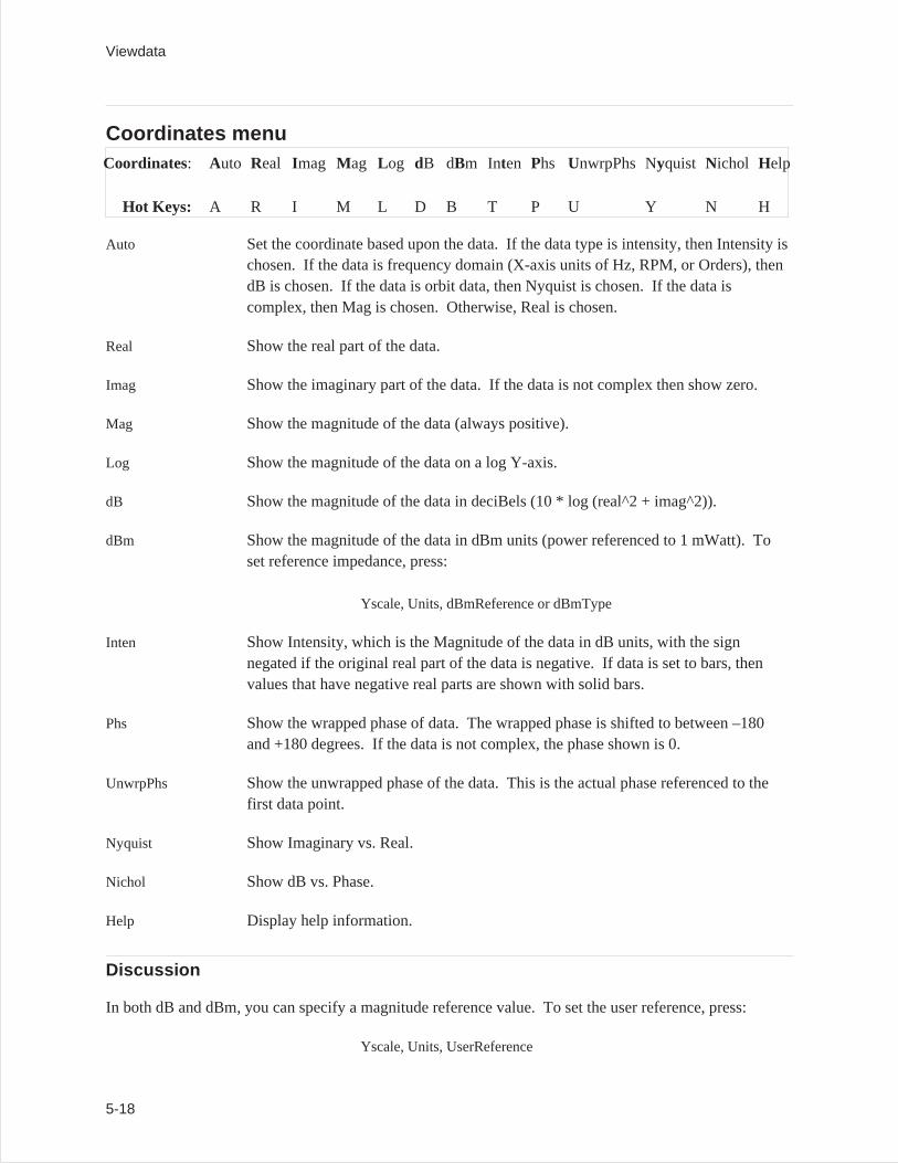
Coordinates menuCoordinates: Auto Real Imag Mag Log dB dBm Inten Phs UnwrpPhs Nyquist Nichol Help
Hot Keys: A R I M L D B T P U Y N H
Auto Set the coordinate based upon the data. If the data type is intensity, then Intensity ischosen. If the data is frequency domain (X-axis units of Hz, RPM, or Orders), thendB is chosen. If the data is orbit data, then Nyquist is chosen. If the data iscomplex, then Mag is chosen. Otherwise, Real is chosen.
Real Show the real part of the data.
Imag Show the imaginary part of the data. If the data is not complex then show zero.
Mag Show the magnitude of the data (always positive).
Log Show the magnitude of the data on a log Y-axis.
dB Show the magnitude of the data in deciBels (10 * log (real^2 + imag^2)).
dBm Show the magnitude of the data in dBm units (power referenced to 1 mWatt). Toset reference impedance, press:
Yscale, Units, dBmReference or dBmType
Inten Show Intensity, which is the Magnitude of the data in dB units, with the signnegated if the original real part of the data is negative. If data is set to bars, thenvalues that have negative real parts are shown with solid bars.
Phs Show the wrapped phase of data. The wrapped phase is shifted to between –180and +180 degrees. If the data is not complex, the phase shown is 0.
UnwrpPhs Show the unwrapped phase of the data. This is the actual phase referenced to thefirst data point.
Nyquist Show Imaginary vs. Real.
Nichol Show dB vs. Phase.
Help Display help information.
Discussion
In both dB and dBm, you can specify a magnitude reference value. To set the user reference, press:
Yscale, Units, UserReference
Viewdata
5-18
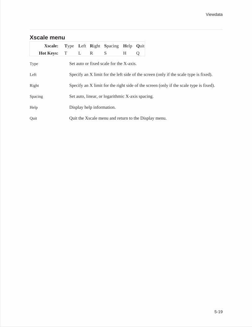
Xscale menuXscale: Type Left Right Spacing Help Quit
Hot Keys: T L R S H Q
Type Set auto or fixed scale for the X-axis.
Left Specify an X limit for the left side of the screen (only if the scale type is fixed).
Right Specify an X limit for the right side of the screen (only if the scale type is fixed).
Spacing Set auto, linear, or logarithmic X-axis spacing.
Help Display help information.
Quit Quit the Xscale menu and return to the Display menu.
Viewdata
5-19
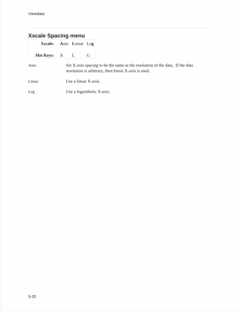
Xscale Spacing menuXscale: Auto L inear Log
Hot Keys: A L G
Auto Set X-axis spacing to be the same as the resolution of the data. If the dataresolution is arbitrary, then linear X-axis is used.
Linear Use a linear X-axis.
Log Use a logarithmic X-axis.
Viewdata
5-20
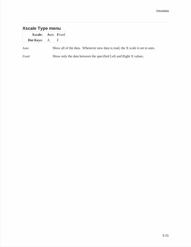
Xscale Type menuXscale: Auto Fixed
Hot Keys: A F
Auto Show all of the data. Whenever new data is read, the X scale is set to auto.
Fixed Show only the data between the specified Left and Right X values.
Viewdata
5-21
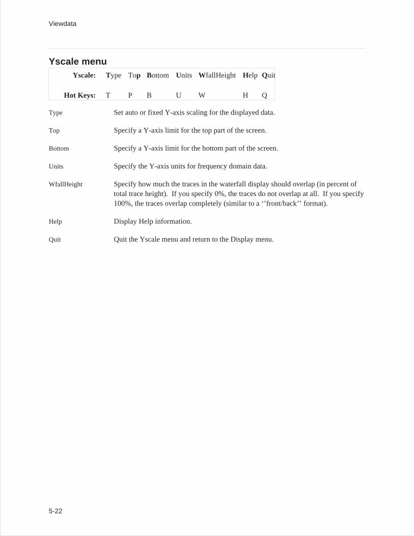
Yscale menuYscale: Type Top Bottom Units WfallHeight Help Quit
Hot Keys: T P B U W H Q
Type Set auto or fixed Y-axis scaling for the displayed data.
Top Specify a Y-axis limit for the top part of the screen.
Bottom Specify a Y-axis limit for the bottom part of the screen.
Units Specify the Y-axis units for frequency domain data.
WfallHeight Specify how much the traces in the waterfall display should overlap (in percent oftotal trace height). If you specify 0%, the traces do not overlap at all. If you specify100%, the traces overlap completely (similar to a ‘’front/back’’ format).
Help Display Help information.
Quit Quit the Yscale menu and return to the Display menu.
Viewdata
5-22
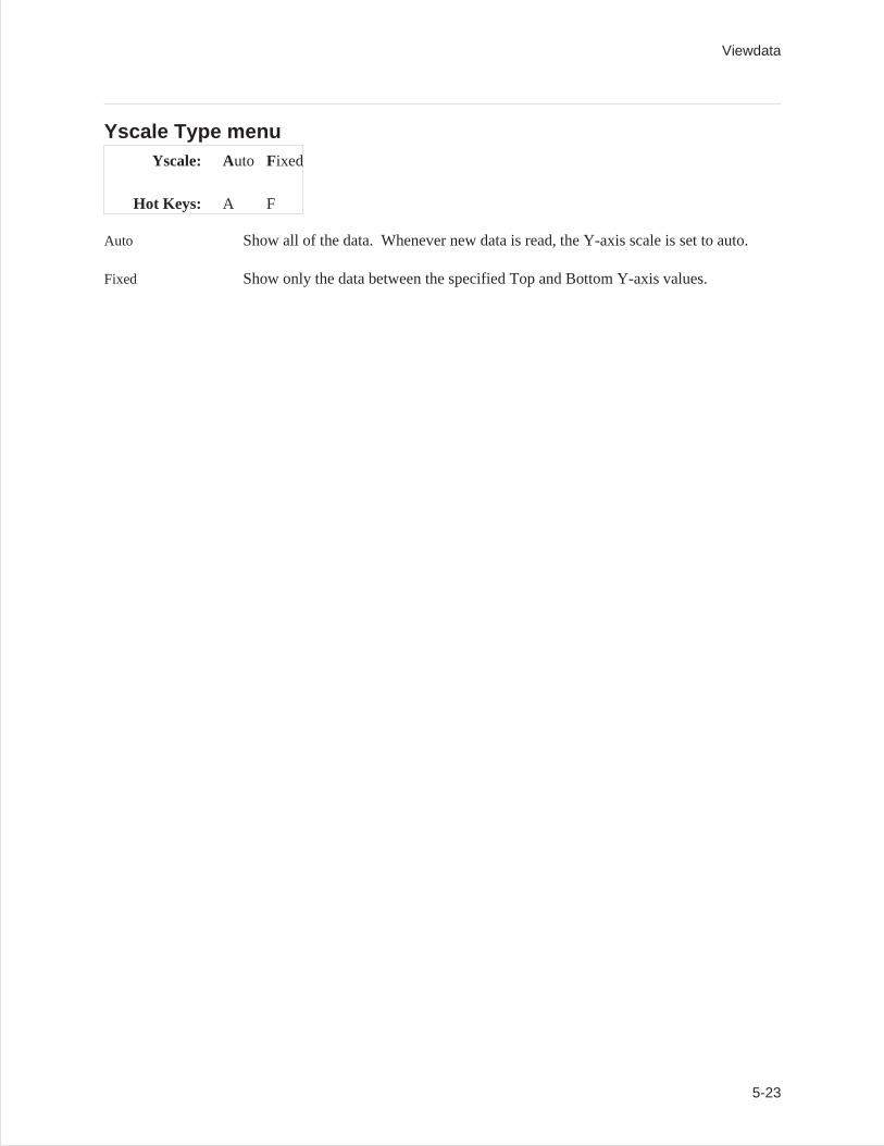
Yscale Type menuYscale: Auto Fixed
Hot Keys: A F
Auto Show all of the data. Whenever new data is read, the Y-axis scale is set to auto.
Fixed Show only the data between the specified Top and Bottom Y-axis values.
Viewdata
5-23
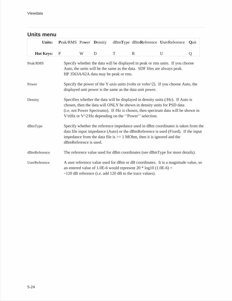
Units menuUnits: Peak/RMS Power Density dBmType dBmReference UserReference Quit
Hot Keys: P W D T R U Q
Peak/RMS Specify whether the data will be displayed in peak or rms units. If you chooseAuto, the units will be the same as the data. SDF files are always peak.HP 3563A/62A data may be peak or rms.
Power Specify the power of the Y-axis units (volts or volts^2). If you choose Auto, thedisplayed unit power is the same as the data unit power.
Density Specifies whether the data will be displayed in density units (/Hz). If Auto ischosen, then the data will ONLY be shown in density units for PSD data(i.e. not Power Spectrums). If /Hz is chosen, then spectrum data will be shown inV/rtHz or V^2/Hz depending on the ‘’Power’’ selection.
dBmType Specify whether the reference impedance used in dBm coordinates is taken from thedata file input impedance (Auto) or the dBmReference is used (Fixed). If the inputimpedance from the data file is >= 1 MOhm, then it is ignored and thedBmReference is used.
dBmReference The reference value used for dBm coordinates (see dBmType for more details).
UserReference A user reference value used for dBm or dB coordinates. It is a magnitude value, soan entered value of 1.0E-6 would represent 20 * log10 (1.0E-6) =−120 dB reference (i.e. add 120 dB to the trace values).
Viewdata
5-24
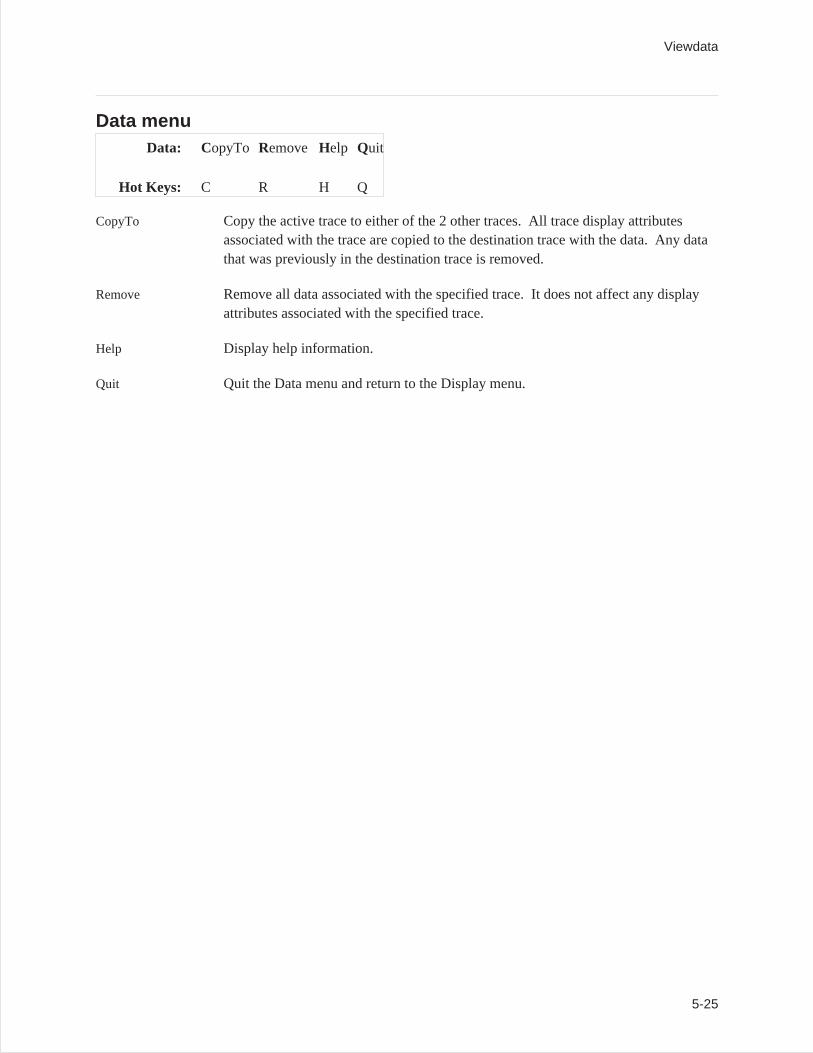
Data menuData: CopyTo Remove Help Quit
Hot Keys: C R H Q
CopyTo Copy the active trace to either of the 2 other traces. All trace display attributesassociated with the trace are copied to the destination trace with the data. Any datathat was previously in the destination trace is removed.
Remove Remove all data associated with the specified trace. It does not affect any displayattributes associated with the specified trace.
Help Display help information.
Quit Quit the Data menu and return to the Display menu.
Viewdata
5-25
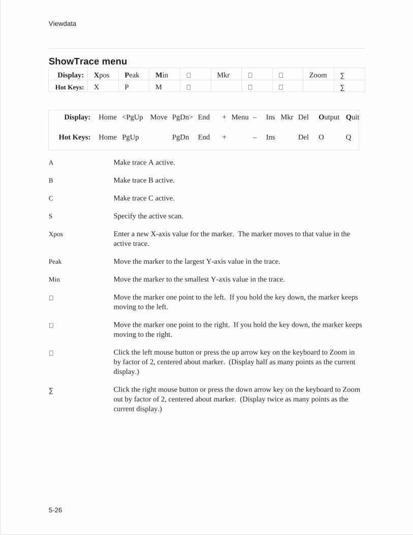
ShowTrace menuDisplay: Xpos Peak M in Mkr Zoom ∑
Hot Keys: X P M ∑
Display: Home <PgUp Move PgDn> End + Menu – Ins Mkr DelOutput Quit
Hot Keys: Home PgUp PgDn End + – Ins Del O Q
A Make trace A active.
B Make trace B active.
C Make trace C active.
S Specify the active scan.
Xpos Enter a new X-axis value for the marker. The marker moves to that value in theactive trace.
Peak Move the marker to the largest Y-axis value in the trace.
Min Move the marker to the smallest Y-axis value in the trace.
Move the marker one point to the left. If you hold the key down, the marker keepsmoving to the left.
Move the marker one point to the right. If you hold the key down, the marker keepsmoving to the right.
Click the left mouse button or press the up arrow key on the keyboard to Zoom inby factor of 2, centered about marker. (Display half as many points as the currentdisplay.)
∑ Click the right mouse button or press the down arrow key on the keyboard to Zoomout by factor of 2, centered about marker. (Display twice as many points as thecurrent display.)
Viewdata
5-26
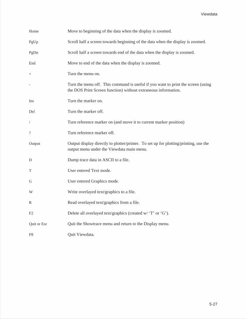
Home Move to beginning of the data when the display is zoomed.
PgUp Scroll half a screen towards beginning of the data when the display is zoomed.
PgDn Scroll half a screen towards end of the data when the display is zoomed.
End Move to end of the data when the display is zoomed.
+ Turn the menu on.
- Turn the menu off. This command is useful if you want to print the screen (usingthe DOS Print Screen function) without extraneous information.
Ins Turn the marker on.
Del Turn the marker off.
/ Turn reference marker on (and move it to current marker position)
? Turn reference marker off.
Output Output display directly to plotter/printer. To set up for plotting/printing, use theoutput menu under the Viewdata main menu.
D Dump trace data in ASCII to a file.
T User entered Text mode.
G User entered Graphics mode.
W Write overlayed text/graphics to a file.
R Read overlayed text/graphics from a file.
F2 Delete all overlayed text/graphics (created w/ ‘T’ or ‘G’).
Quit or Esc Quit the Showtrace menu and return to the Display menu.
F8 Quit Viewdata.
Viewdata
5-27
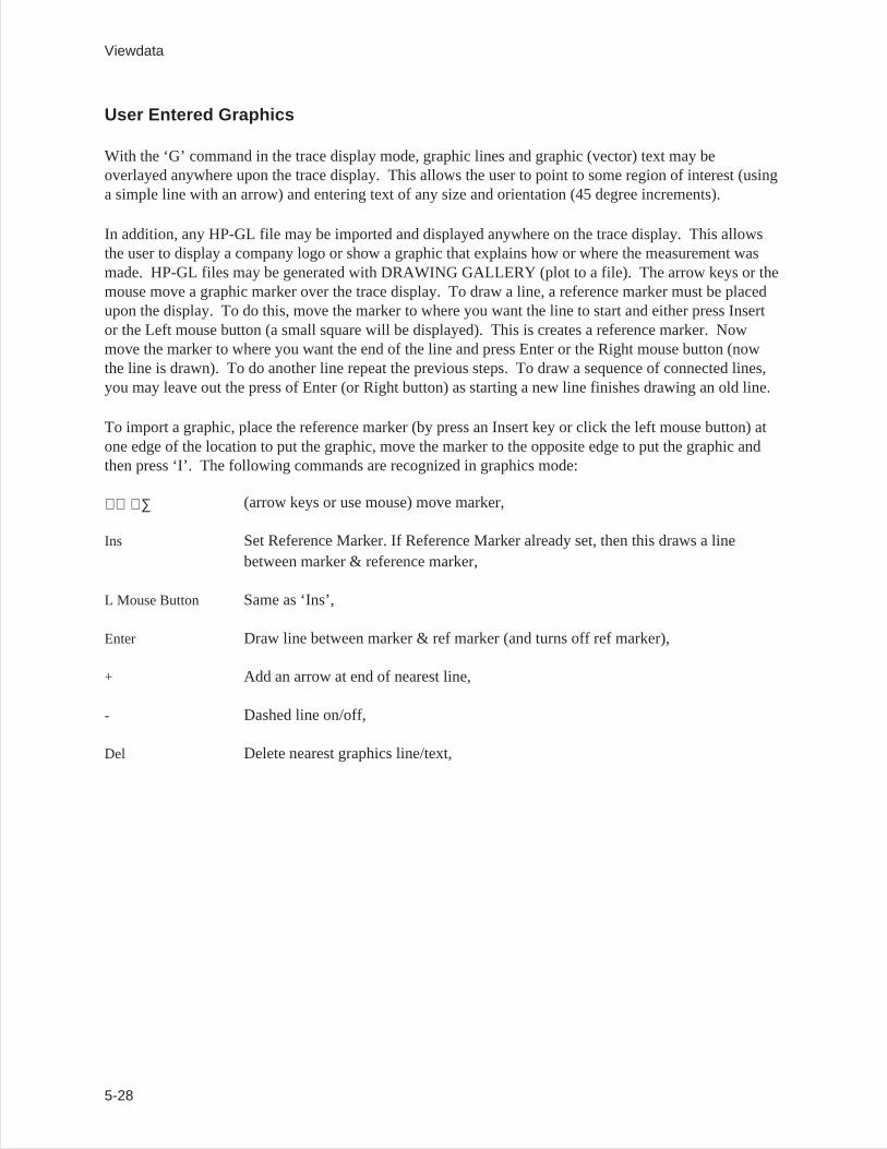
User Entered Graphics
With the ‘G’ command in the trace display mode, graphic lines and graphic (vector) text may beoverlayed anywhere upon the trace display. This allows the user to point to some region of interest (usinga simple line with an arrow) and entering text of any size and orientation (45 degree increments).
In addition, any HP-GL file may be imported and displayed anywhere on the trace display. This allowsthe user to display a company logo or show a graphic that explains how or where the measurement wasmade. HP-GL files may be generated with DRAWING GALLERY (plot to a file). The arrow keys or themouse move a graphic marker over the trace display. To draw a line, a reference marker must be placedupon the display. To do this, move the marker to where you want the line to start and either press Insertor the Left mouse button (a small square will be displayed). This is creates a reference marker. Nowmove the marker to where you want the end of the line and press Enter or the Right mouse button (nowthe line is drawn). To do another line repeat the previous steps. To draw a sequence of connected lines,you may leave out the press of Enter (or Right button) as starting a new line finishes drawing an old line.
To import a graphic, place the reference marker (by press an Insert key or click the left mouse button) atone edge of the location to put the graphic, move the marker to the opposite edge to put the graphic andthen press ‘I’. The following commands are recognized in graphics mode:
∑ (arrow keys or use mouse) move marker,
Ins Set Reference Marker. If Reference Marker already set, then this draws a linebetween marker & reference marker,
L Mouse Button Same as ‘Ins’,
Enter Draw line between marker & ref marker (and turns off ref marker),
+ Add an arrow at end of nearest line,
- Dashed line on/off,
Del Delete nearest graphics line/text,
Viewdata
5-28
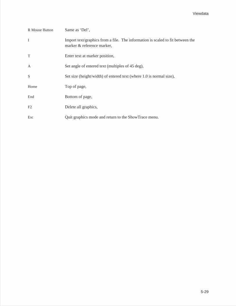
R Mouse Button Same as ‘Del’,
I Import text/graphics from a file. The information is scaled to fit between themarker & reference marker,
T Enter text at marker position,
A Set angle of entered text (multiples of 45 deg),
S Set size (height/width) of entered text (where 1.0 is normal size),
Home Top of page,
End Bottom of page,
F2 Delete all graphics,
Esc Quit graphics mode and return to the ShowTrace menu.
Viewdata
5-29
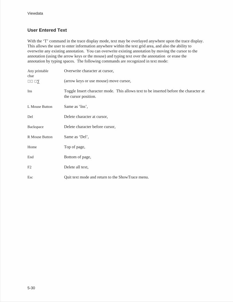
User Entered Text
With the ‘T’ command in the trace display mode, text may be overlayed anywhere upon the trace display.This allows the user to enter information anywhere within the text grid area, and also the ability tooverwrite any existing annotation. You can overwrite existing annotation by moving the cursor to theannotation (using the arrow keys or the mouse) and typing text over the annotation or erase theannotation by typing spaces. The following commands are recognized in text mode:
Any printablechar
Overwrite character at cursor,
∑ (arrow keys or use mouse) move cursor,
Ins Toggle Insert character mode. This allows text to be inserted before the character atthe cursor position.
L Mouse Button Same as ‘Ins’,
Del Delete character at cursor,
Backspace Delete character before cursor,
R Mouse Button Same as ‘Del’,
Home Top of page,
End Bottom of page,
F2 Delete all text,
Esc Quit text mode and return to the ShowTrace menu.
Viewdata
5-30
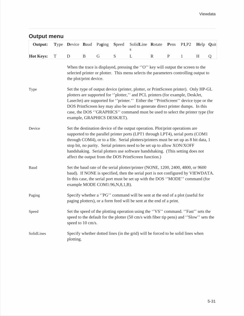
Output menuOutput: T ype Device Baud Paging Speed SolidL ine
sRotate Pens P1,P2 Help Quit
Hot Keys: T D B G S L R P 1 H Q
When the trace is displayed, pressing the ‘’O’’ key will output the screen to theselected printer or plotter. This menu selects the parameters controlling output tothe plot/print device.
Type Set the type of output device (printer, plotter, or PrintScreen printer). Only HP-GLplotters are supported for ‘’plotter,’’ and PCL printers (for example, DeskJet,LaserJet) are supported for ‘’printer.’’ Either the ‘’PrintScreen’’ device type or theDOS PrintScreen key may also be used to generate direct printer dumps. In thiscase, the DOS ‘’GRAPHICS’’ command must be used to select the printer type (forexample, GRAPHICS DESKJET).
Device Set the destination device of the output operation. Plot/print operations aresupported to the parallel printer ports (LPT1 through LPT4), serial ports (COM1through COM4), or to a file. Serial plotters/printers must be set up as 8 bit data, 1stop bit, no parity. Serial printers need to be set up to allow XON/XOFFhandshaking. Serial plotters use software handshaking. (This setting does notaffect the output from the DOS PrintScreen function.)
Baud Set the baud rate of the serial plotter/printer (NONE, 1200, 2400, 4800, or 9600baud). If NONE is specified, then the serial port is not configured by VIEWDATA.In this case, the serial port must be set up with the DOS ‘’MODE’’ command (forexample MODE COM1:96,N,8,1,B).
Paging Specify whether a ‘’PG’’ command will be sent at the end of a plot (useful forpaging plotters), or a form feed will be sent at the end of a print.
Speed Set the speed of the plotting operation using the ‘’VS’’ command. ‘’Fast’’ sets thespeed to the default for the plotter (50 cm/s with fiber tip pens) and ‘’Slow’’ sets thespeed to 10 cm/s.
SolidLines Specify whether dotted lines (in the grid) will be forced to be solid lines whenplotting.
Viewdata
5-31
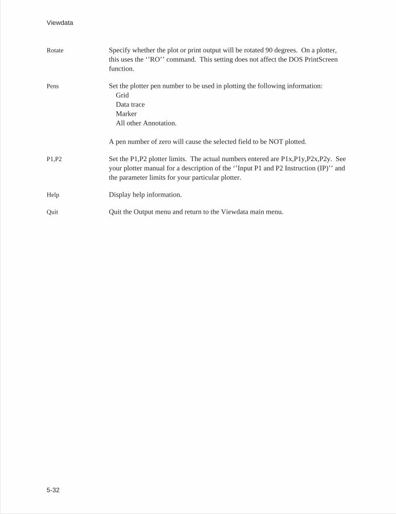
Rotate Specify whether the plot or print output will be rotated 90 degrees. On a plotter,this uses the ‘’RO’’ command. This setting does not affect the DOS PrintScreenfunction.
Pens Set the plotter pen number to be used in plotting the following information:GridData traceMarkerAll other Annotation.
A pen number of zero will cause the selected field to be NOT plotted.
P1,P2 Set the P1,P2 plotter limits. The actual numbers entered are P1x,P1y,P2x,P2y. Seeyour plotter manual for a description of the ‘’Input P1 and P2 Instruction (IP)’’ andthe parameter limits for your particular plotter.
Help Display help information.
Quit Quit the Output menu and return to the Viewdata main menu.
Viewdata
5-32
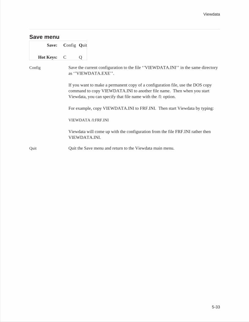
Save menuSave: Config Quit
Hot Keys: C Q
Config Save the current configuration to the file ‘’VIEWDATA.INI’’ in the same directoryas ‘’VIEWDATA.EXE’’.
If you want to make a permanent copy of a configuration file, use the DOS copycommand to copy VIEWDATA.INI to another file name. Then when you startViewdata, you can specify that file name with the /I: option.
For example, copy VIEWDATA.INI to FRF.INI. Then start Viewdata by typing:
VIEWDATA /I:FRF.INI
Viewdata will come up with the configuration from the file FRF.INI rather thenVIEWDATA.INI.
Quit Quit the Save menu and return to the Viewdata main menu.
Viewdata
5-33

6
Using SDF Data with C Programs
SDF Library Functions
This chapter provides information on the SDF library functions. These functions are located in\SDFLIB\SDFUTIL.LIB. The SDF library functions are written on a much higher level to help you moreeasily get at the data that you need.
When using these functions, include these include files (located in \SDFLIB) in your C programs:
• SDF_COMM.H• SDF_BASI.H• SDF_UTIL.H
There are three C example programs (located in \SDFLIB) that show you how to use the SDF Libraryfunctions:
SDF.C Prints the headers of an SDF file.
SDFDATA.C Prints all the data (applying corrections) in an SDF file.
SDFMPY.C Multiplies first data result in the SDF file by the factor specified. This programdemonstrates reading and writing data to an SDF file.
Caution SDFMPY.C changes data in the selected SDF file. Make a backup copy of your SDFfile if you want to preserve its contents.
6-1
The Standard Data Format
All measurement data stored by the HP 3566A, HP 3567A, HP 35665A, HP 35670A, HP 89410A, andHP 89440A is in a file format called Standard Data Format (SDF). Data saved in Standard Data Formatis the pure measurement data, with no engineering units or window corrections applied to it. It is storedin binary, along with accompanying header information, and represents the highest resolution dataavailable from the analyzer. An SDF file is composed of several headers followed by the measurementdata. The headers contain information such as measurement settings that help reconstruct the data.
Appendix B, ‘’Standard Data Format,’’ describes the structure of SDF in detail. Read appendix B tobecome familiar with SDF.
Using SDF Data with C Programs
6-2
SdfOpen
Syntax short SdfOpen (char far *filename);
Returns an integer(short) between 0 and 5 containing a file number. A return of 0 indicatesan error; 1 to 5 indicates a valid file.
This function attempts to open an SDF file with the indicated file name. If the file is found, the formattype of the file is read. If it is a binary SDF file, the file number is recorded in the current list of openSDF files and returned. The returned file number may then be passed to other SDF functions to specifythe file.
Using SDF Data with C ProgramsSdfOpen
6-3
SdfClose
Syntax int SdfClose (short fn);
Returns an integer(short) of zero or minus one. A return of 0 indicates no error; a return of-1 indicates an error.
This function closes an open file with the indicated file number and decrements the current list of openSDF files.
Using SDF Data with C ProgramsSdfClose
6-4
SdfFileHdr
Syntax int SdfFileHdr (short fn, struct SDF_FILE_HDR far *fileHdr);
Returns an integer(short) of zero or minus one. A return of 0 indicates no error; a return of-1 indicates an error.
This function reads the file-header information from an open SDF file, wherefn is the number of the openSDF file (for details, see SdfOpen). The information is put in the SDF_FILE_HDR structure, wherefileHdr is the pointer to the structure.
The SDF file header record contains information such as the application (instrument) that created it, thetime stamp, the index of all other types of records in the file and the offsets of those records from thebeginning of the file.
Using SDF Data with C ProgramsSdfFileHdr
6-5
SdfMeasHdr
Syntax int SdfMeasHdr (short fn, struct SDF_MEAS_HDR far *measHdr );
Returns an integer(short) of zero or minus one. A return of 0 indicates no error; a return of-1 indicates an error.
This function reads the measurement-header information from an open SDF file, wherefn is the numberof the open SDF file (for details, see SdfOpen). The information is put in the SDF_MEAS_HDRstructure, where measHdr is the pointer to the structure.
The SDF measurement header record contains information such as the frequency span, start and center,block size, average type and count, etc. There is always one measurement header record in every SDFfile.
Using SDF Data with C ProgramsSdfMeasHdr
6-6
SdfDataHdr
Syntax int SdfDataHdr (short fn, short dataNo ,struct SDF_DATA_HDR far *dataHdr);
Returns an integer(short) of zero or minus one. A return of 0 indicates no error; a return of-1 indicates an error.
This function reads the data-header information from an open SDF file, wherefn is the number of theopen SDF file (for details, see SdfOpen). The information is put in the SDF_DATA_HDR structure,where dataHdr is the pointer to the structure.
Note ThedataNo parameter selects the data result that you want to examine. Mostinstruments have only 1 data result, therefore, you will usually specify 0 (zero) for thisparameter, which selects the first data result.
The SDF data header record contains information for a specific measurement data type. It contains theindex to the first vector header record as well as the total number of rows and columns (vectors)associated with it. It also contains fields describing the data type, number of points per trace, X-axisspacing information, Y-axis data format. There is one data header record for every measurement resulttype in the SDF file.
Using SDF Data with C ProgramsSdfDataHdr
6-7
SdfVectHdr
Syntax int SdfVectHdr (short fn, short dataNo, short rowNo,short colNo, struct SDF_VECTOR_HDR far *vectHdr);
Returns an integer(short) of zero or minus one. A return of 0 indicates no error; a return of-1 indicates an error.
This function reads the vector-header information from an open SDF file, wherefn is the number of theopen SDF file (for details, see SdfOpen). The information is put in the SDF_VECTOR_HDR structure,where vectHdr is the pointer to the structure.
Note See SdfYdata for a description of the parameters used with this function.
Two fields in the vector header record, the_CHANNEL_record[0] and the_CHANNEL_record[1],contain indexes to channel header records containing the channel numbers associated with that vector.Although the the_CHANNEL_record[0] and the_CHANNEL_record[1] fields do not refer to actualchannel numbers themselves, in the HP 3566A/3567A the channel number is always 1 plus the value inthese fields, since channel header records are a contiguous block starting from channel 1 and the indexesto the channel header records start at 0. For single channel measurements, the_CHANNEL_record[1]will always be –1.
The vector header record is mainly used to store the indexes of associated channel header records and theexponents (power) applied to the corresponding trace data.
Using SDF Data with C ProgramsSdfVectHdr
6-8
SdfChanHdr
Syntax int SdfChanHdr (short fn, short chanNo,struct SDF_CHANNEL_HDR far *chanHdr);
Returns an integer(short) of zero or minus one. A return of 0 indicates no error; a return of-1 indicates an error.
This function reads the channel-header information from an open SDF file, wherefn is the number of theopen SDF file (for details, see SdfOpen). The information is put in the SDF_CHANNEL_HDR structure,where chanHdr is the pointer to the structure.
There is a separate channel header for each channel. UsechanNo to select a channel.
Note A chanNoof zero selects channel 1; achanNoof one selects channel 2, and so forth.
The SDF channel header record contains information pertaining to the channel from which the data wasreceived as well as the window function and engineering unit correction factors to be applied to the data.
Using SDF Data with C ProgramsSdfChanHdr
6-9
SdfScanStruct
Syntax int SdfScanStruct (short fn,struct SDF_SCAN_STRUCT far *scanStruct);
Returns an integer(short) of zero or minus one. A return of 0 indicates no error; a return of-1 indicates an error.
This function reads scan information from an open SDF file, wherefn is the number of the open SDF file(for details, see SdfOpen). The information is put in the SDF_SCAN_STRUCT structure, wherescanStruct is the pointer to the structure.
Using SDF Data with C ProgramsSdfScanStruct
6-10
SdfScanBig
Syntax int SdfScanBig (short fn, struct SDF_SCAN_BIG far *scanBig);
Returns an integer (short) of greater than zero, zero, or minus one. A return of greater thanzero indicates that an SDF_SCAN_BIG header was found (returnsSDF_SCAN_BIG_TYPE) or one was created from an SDF_SCAN_STRUCT(returns SDF_SCAN_STRUCT_TYPE). A return of 0 indicates that no scan headerof any type was found. A return of−1 indicates an error.
This function reads the scan information from an open SDF file, wherefn is the number of the open SDFfile (for details, see SdfOpen). The information is put in the SDF_SCAN_BIG structure, wherescanBigis the pointer to the structure. If an SDF_SCAN_BIG record is not in the file, one will be created fromthe SDF_SCAN_STRUCT record in the file.
Using SDF Data with C ProgramsSdfScanBig
6-11
SdfScanVar
Syntax int SdfScanVar (short fn, short varInx, struct SDF_SCAN_VAR far *scanVar);
Returns an integer (short) of zero or minus one. A return of 0 indicates no error; a return of−1 indicates an error.
This function reads the scan variable information from an open SDF file, wherefn is the number of theopen SDF file (for details, see SdfOpen). The information is put in the SDF_SCAN_VAR structure,wherescanVaris the pointer to the structure.
ThevarInxparameter selects the scan variable that you want to examine. The first variable (varInxequalto zero) is actually an SDF_SCAN_VAR record created from the SDF_SCAN_STRUCT record in theSDF file. Most instruments don’t have true SDF_SCAN_VAR records, but do have theSDF_SCAN_STRUCT record, so you will usually specify 0 (zero) for this parameter. The HP 89410Aand HP 89440A do use 3 addition scan variable records for waterfall data, so you may specify avarInxfrom 0 to 3.
Using SDF Data with C ProgramsSdfScanVar
6-12
SdfScansUsed
Syntax long SdfScansUsed (short fn);
Returns A long integer of greater than or equal to minus one. The return value is thenumber of scans in the SDF file. A return of 0 indicates no scan data; a return of−1indicates an error.
This function returns the number of scans in an open SDF file, wherefn is the number of the open SDFfile (for details, see SdfOpen).
The number of scans is in the SDF_SCAN_BIG header if it exists in the file, or theSDF_SCAN_STRUCT header if it exists in the file. If neither of these headers are in the file, then thereis no scan data.
Using SDF Data with C ProgramsSdfScansUsed
6-13
SdfYdata
Syntax int SdfYdata (short fn, long offset, short dataNo,short rowNo, short colNo, long scanNo, long pnts,short dataType, float far *y);
Returns an integer(short) of zero or minus one. A return of 0 indicates no error; a return of-1 indicates an error.
This function reads Y-axis data from an open SDF file and puts it in an array, wherey is the pointer to thearray, andfn is the number of the open SDF file (for details, see SdfOpen).
Theoffsetis the number of data points to skip before reading the data. One situation where an offset isuseful is if you are reading data in multiple passes. If you don’t want to use an offset, specify an offset ofzero.
ThedataNoselects the data result that you want to examine–most instruments have only 1 data result,therefore, you will usually specify zero for this parameter, which selects the first data result. In general,rowNo selects the channel, scanNo selects the trace (in the case of waterfall or spectrogrammeasurements), and colNo is not used. A rowNo of zero selects channel 1 and a scanNo of zero selectsthe first trace. For further details, see chapter 2.
Note All parameters are zero based. Therefore, for parameters such as dataNo, rowNo,colNo, and scanNo, zero selects the first item, as described in the above paragraph.
Furthermore, you must include all parameters. For unused parameters,specify zero.
Thepntsare the number of data points you want to read. For example, a complex value is 2 points. Todetermine the number of data points in the record, see ‘’Reconstructing a Trace’’ in appendix B.
Using SDF Data with C ProgramsSdfYdata
6-14
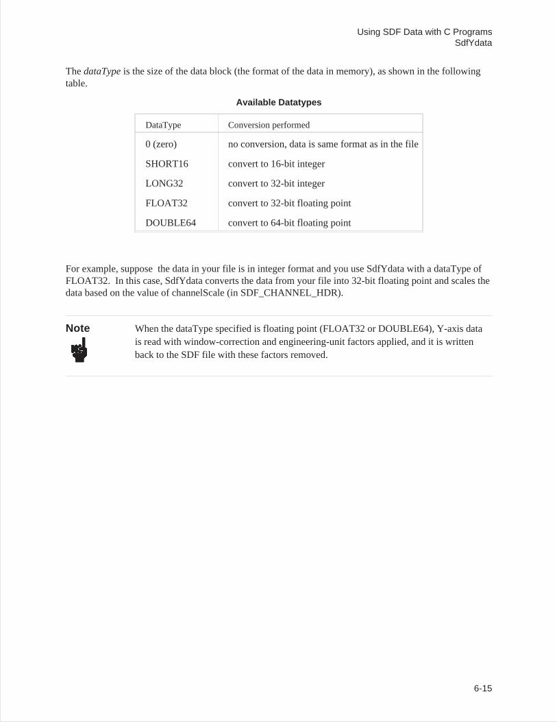
ThedataTypeis the size of the data block (the format of the data in memory), as shown in the followingtable.
Available Datatypes
DataType Conversion performed
0 (zero) no conversion, data is same format as in the file
SHORT16 convert to 16-bit integer
LONG32 convert to 32-bit integer
FLOAT32 convert to 32-bit floating point
DOUBLE64 convert to 64-bit floating point
For example, suppose the data in your file is in integer format and you use SdfYdata with a dataType ofFLOAT32. In this case, SdfYdata converts the data from your file into 32-bit floating point and scales thedata based on the value of channelScale (in SDF_CHANNEL_HDR).
Note When the dataType specified is floating point (FLOAT32 or DOUBLE64), Y-axis datais read with window-correction and engineering-unit factors applied, and it is writtenback to the SDF file with these factors removed.
Using SDF Data with C ProgramsSdfYdata
6-15
SdfYdataWrite
Syntax int SdfYdataWrite (short fn, long offset, short dataNo,short rowNo, short colNo, long scanNo, long pnts,short dataType, float far *y);
Returns an integer(short) of zero or minus one. A return of 0 indicates no error; a return of-1 indicates an error.
This function writesY-axis data from an array and puts it in an open SDF file , where y is the pointer tothe array, andfn is the number of the open SDF file (for details, see SdfOpen).
When you use SdfYdataWrite, data is converted back into its original form before writing to your file.For example, suppose the data in your file is in integer format and you use SdfYdata with a dataType ofFLOAT32. In this case, SdfYdata converts the data from your file into 32-bit floating point and scales thedata based on the value of channelScale. If you use SdfYdataWrite to write data back to your file, thedata is converted back into integer form before it is written to your file. If any data value exceedschannelScale (in SDF_CHANNEL_HDR), that data will be clipped.
Note When the dataType specified is floating point (FLOAT32 or DOUBLE64), Y-axis datais read with window-correction and engineering-unit factors applied, and it is writtenback to the SDF file with these factors removed. For further details about dataType, andfor a description of the parameters used with this function, see SdfYdata .
Using SDF Data with C ProgramsSdfYdataWrite
6-16
SdfXdata
Syntax int SdfXdata (short fn, long offset, short dataNo,short rowNo, short colNo, long pnts, short dataType,float far *x);
Returns an integer(short) of zero or minus one. A return of 0 indicates no error; a return of-1 indicates an error.
This function reads X-axis data from an open SDF file and puts it in an array, where x is the pointer to thearray, andfn is the number of the open SDF file (for details, see SdfOpen).
An xdata header is only included in the SDF file for data types that use arbitrary X-axis spacing,otherwise all X-axis spacing is defined by fields in the data record header.
The xdata header contains all of the X-axis data for a single vector and corresponds to the equivalentydata header.
Note See SdfYdata for a list of valid dataTypes and for a description of the parameters usedwith this function.
Using SDF Data with C ProgramsSdfXdata
6-17
SdfScanData
Syntax int SdfScanData (short fn, long offset, short varInx,long pnts, short dataType, float far *s);
Returns an integer(short) of zero or minus one. A return of 0 indicates no error; a return of-1 indicates an error.
This function reads scan data from an open SDF file and puts it in an array, wheres is the pointer to thearray, andfn is the number of the open SDF file (for details, see SdfOpen).
In the HP 3566A, 3567A and 35665A, map lines are stored as scan data blocks.
ThevarInxparameter selects the scan variable data that you want to read. The first variable (varInxequalto zero) is actually scan data from the SDF_SCAN_STRUCT record in the SDF file. Most instrumentsdon’t have SDF_SCAN_VAR records, but do have the SDF_SCAN_STRUCT RECORD, so you willusually specify 0 (zero) for this parameter. The HP 89410A and HP 89440A do use 3 addition scanvariable records for waterfall data, so you may specify avarInx from 0 to 3.
Using SDF Data with C ProgramsSdfScanData
6-18
SdfTrunc
Syntax long SdfTrunc (short fn);
Returns a long integer or minus one (-1 indicates an error).
This function returns a long integer. This integer is the accumulated number of times that data wastruncated by any of these functions:
• SdfYdata()• SdfYdataWrite()• SdfXdata()• SdfScanData()
Separate truncation counts are kept for each open file. Therefore, you must specify the number (fn) of theopen SDF file with this function (for details aboutfn, see SdfOpen).
The count for an SDF file is cleared (reset) when the file is open or after calling this routine.
Using SDF Data with C ProgramsSdfTrunc
6-19
SdfCommentHdr
Syntax int SdfCommentHdr (short fn, short commNo, structSDF_COMMENT_HDR far *commHdr);
Returns an integer (short) of zero or minus one. A return of 0 indicates no error; a return of−1 indicates an error.
This function read the comment-header information from an open SDF file, wherefn is the number of theopen SDF file (for details, see SdfOpen). The information is put in the SDF_COMMENT_HDRstructure, wherecommHdris the pointer to the structure.
ThecommNoparameter selects the comment header that you want to examine. Most instruments haveonly one comment header, so you will usually specify 0 (zero), which selects the first comment.
The SDF comment header record contains information about a comment associated with this data file. Itcontains the type of comment, the length of the comment, the maximum length of the comment, and towhat part of the file the comment applies. The actual comment follows the comment header. Use theSdfCommentRead function to read the comment, and the SdfCommentWrite function to write to thecomment area.
Using SDF Data with C ProgramsSdfCommentHdr
6-20
SdfCommentRead
Syntax long SdfCommentRead (short fn, short commNo, long offset, long size, char far *buf);
Returns a long integer of greater than or equal to minus one. The return value is the numberof characters of comment actually read; a return of−1 indicates an error.
This function reads comment data from an open SDF file and puts it in a character array, wherebuf is thepointer to the array, andfn is the number of the open SDF file (for details, see SdfOpen).
ThecommNoparameter selects the comment header from which you want to read. Most instrumentshave only one comment header, so you will usually specify 0 (zero), which selects the first comment.
Theoffsetparameter is the number of characters to skip before reading the data. One situation where anoffset is useful is if you are reading data in multiple passes. If you don’t want to use an offset, specify anoffset of zero.
Thesizeparameter is the maximum number of characters you want to read. This function returns theactual number of characters that you read.
Using SDF Data with C ProgramsSdfCommentRead
6-21
SdfCommentWrite
Syntax long SdfCommentWrite (short fn, short commNo, long offset, long size, char far *buf);
Returns a long integer of greater than or equal to minus one. The return value is the numberof characters of comment actually written; a return of−1 indicates an error.
This function writes a character array to the comment area in an open SDF file, wherebuf is the pointer tothe array, andfn is the number of the open SDF file (for details, see SdfOpen).
ThecommNoparameter selects the comment header to which you want to write. Most instruments haveonly one comment header, so you will usually specify 0 (zero), which selects the first comment.
Theoffsetparameter is the number of characters to skip before writing the data. One situation where anoffset is useful is if you are writing data in multiple passes. If you don’t want to use an offset, specify anoffset of zero.
Thesizeparameter is the maximum number of characters you want to write. This function returns theactual number of characters that you wrote. Since the comment area is a fixed size (fixed at the time offile creation) you may not be able to write the number of characters specified.
This function automatically updates the comment size in the appropriate SDF_COMMENT_HDR.
Using SDF Data with C ProgramsSdfCommentWrite
6-22
7
MATLAB MEX-Files & M-Files
Overview
MATLAB lets you call user programs (MEX-files) from MATLAB as if they were built-in MATLABfunctions. MEX-files are usable only on PC-MATLAB or AT-MATLAB. They do not work on386-MATLAB.
Note MATLAB, PC-MATLAB, and AT-MATLAB are trademarks ofThe MathWorks, Inc.
M-files are command scripts. MATLAB executes the commands found in M-files, instead of gettinginput from the keyboard.
This section describes the MEX-files and M-files for MATLAB that operate on SDF data.
Installing MEX-Files and M-files
To install the MEX-files and the M-files, copy *.m and *.mex (in the \matlab directory) to any directoryon your MATLAB search path (see MATLABPATH in your MATLAB User’s Guide). Copymatdemo.tim to this directory: \analyzer\tc. Copy sdftoml.exe to this directory: \analyzer\util(sdftoml.exe is available as part of the Standard Data Format Utilities).
7-1
filtrsdf.mex
Syntax filtersdf (b, a, name, dataNo, rowNo, colNo)
Returns not applicable
This MATLAB subroutine digitally filters SDF data (time capture data).
Caution This MEX-file will modify your SDF file. You may want to make a back up copy of theSDF file before using this subroutine.
Parameter Definitions
Parameter Definition
b Digital filter coefficients (numerator)
a Digital filter coefficients (denominator)
name name of SDF file to filter
dataNo data result to filter (default = 0, first result)
rowNo row number to filter (default = 0, first row)
colNo column number to filter (default = 0, first column)
All scans in a file are filtered. If the result is a time capture, the filter is cleared only once at the start ofthe data. Otherwise, the filter is cleared at the start of each scan.
For a time capture file, dataNo is 0 (captured data is always the first result in the file), rowNo is thechannel number (0 is channel 1, 1 is channel 2), and colNo is always 0. For example, to filter channel 2of the time capture file ‘TEST.TIM’, specify
filtersdf (b, a, ‘TEST.TIM’, 0, 1);
Note This MEX-file requires the MATLAB Signal Processing Toolbox, because it uses the‘filter’ function.
MATLAB MEX-Files & M-Filesfiltrsdf.mex
7-2

matdemo.tim
This file contains data that can be used by the tcdemo.m M-file. The data represents a 4 channel, 12,800Hertz , baseband, time capture with broadband noise on all 4 channels.
MATLAB MEX-Files & M-Filesmatdemo.tim
7-3
tcdemo.m
This M-file is a demonstration. It shows you how to digitally filter HP3566A/67A time-capture datausing the MATLAB Signal Processing Toolbox.
This demonstration assumes that matdemo.tim exists in \analyzer\tc, and that it is
• A 4 channel time-capture file, with• a span of 12,800 Hertz.
Note This demonstration overwrites the data in matdemo.tim with refiltered data. Therefore,make a backup copy of matdemo.tim if you want to preserve its contents.
MATLAB MEX-Files & M-Filestcdemo.m
7-4
tcdemo2.m
This M-file is a demonstration. It shows you how to compare the FRF measurement results of thedigitally filtered, HP3566/67A time-capture data and the orginal filter shapes generated by thePC-MATLAB Signal Processing Toolbox.
This demonstration requires these files:
• \analyzer\data\matfrf.dat• \analyzer\utils\sdftoml.exe
The file sdftoml.exe is provided with the SDF utilities; the file matfrf.dat is not. You must creatematfrf.dat on your HP3566/67A. To create matfrf.dat, perform the following steps:
1. Load the matdemo.tim time-capture file into the HP 3566/67A.2. Run a stable-average measurement.3. Save the results to \analyzer\data\matfrf.dat (using Save Data).
Note The file matdemo.tim is provided with the SDF utilities. It is a 4 channel,FRF time-capture file, created with a span of 12,800 Hertz.
MATLAB MEX-Files & M-Filestcdemo2.m
7-5

8
Mathcad ® Examples
Mathcad is a registered trademark of MathSoft, Inc., 201 Broadway, Cambridge MA 02139.
Overview
The Mathcad examples described in this chapter are in the mathcad directory. From within Mathcad, youcan read and/or print the files in that directory for more detailed information about these examples.
The mathcad directory contains several example Mathcad 4.0 files that demonstrate how to createwaveforms and filters for use with the HP89410A and HP89440A (including option AYA). Althoughdesigned for use with the HP894x0A, the general approach to using Mathcad data with SDF is similar forall instruments incorporating SDF capability.
Each of the following files is described briefly below:
• mathcad\signals\ofstsine.mcd• mathcad\signals\gmsk.mcd• mathcad\signals\qpsk.mcd• mathcad\filters\gauss.mcd• mathcad\filters\raiscos.mcd• mathcad\filters\rootcos.mcd
Mathcad Files
mathcad\signals\ofstsine.mcd
This file contains an example of how to create a waveform that can be used with the HP894x0A arbitrarysource. The complex waveform (that is, real and imaginary components) is a simple sinewave that can beoffset from the center frequency of the measurement.
mathcad\signals\gmsk.mcd
This file contains an example of how to create a pulsed Gaussian MSK waveform for use with theHP894x0A arbitrary source. In addition to being pulsed, the signal can be modified to have imperfectionssuch as IQ gain imbalance and origin offset.
8-1
mathcad\signals\qpsk.mcd
This file contains an example of how to create a pulsed QPSK waveform for use with the HP894x0Aarbitrary source. The waveform is filtered using a root-raised cosine ISI filter.
mathcad\filters\gauss.mcd
This file contains an example of how to create a custom gaussian filter for use with the AYA (Digitaldemodulation) option for the HP894x0A Vector Signal Analyzer.
mathcad\filters\raiscos.mcd
This file contains an example of how to create a raised cosine filter for use with the AYA (Digitaldemodulation) option for the HP894x0A Vector Signal Analyzer.
mathcad\filters\rootcos.mcd
This file contains an example of how to create a root-raised cosine filter for use with the AYA (Digitaldemodulation) option for the HP894x0A Vector Signal Analyzer.
Mathcad® Examples
8-2
A
SDF to PC-MATLAB and MATRIXx examples
Introduction
The following examples demonstrate:
• How to move an HP 3563A (or HP 3562A) file to MATRIXx or PC-MATLAB file format.
• How to load a converted file into MATRIXx.
• How to load a converted file into PC-MATLAB.
A-1
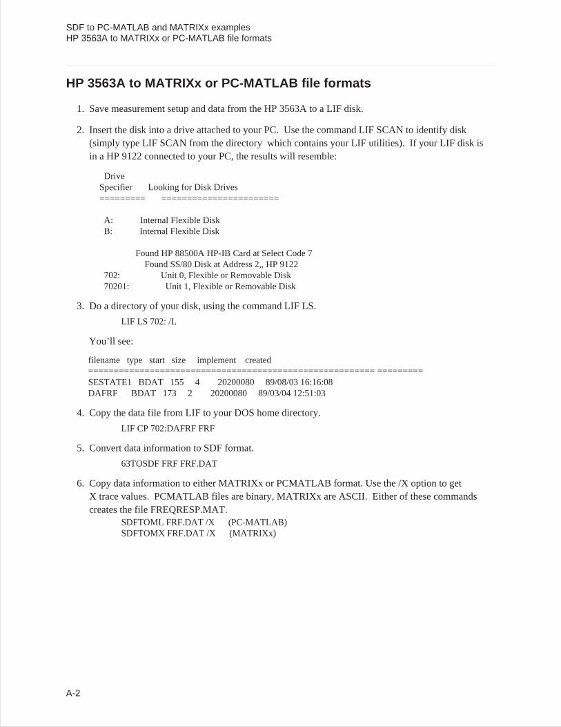
HP 3563A to MATRIXx or PC-MATLAB file formats
1. Save measurement setup and data from the HP 3563A to a LIF disk.
2. Insert the disk into a drive attached to your PC. Use the command LIF SCAN to identify disk(simply type LIF SCAN from the directory which contains your LIF utilities). If your LIF disk isin a HP 9122 connected to your PC, the results will resemble:
DriveSpecifier Looking for Disk Drives========= =======================
A: Internal Flexible DiskB: Internal Flexible Disk
Found HP 88500A HP-IB Card at Select Code 7Found SS/80 Disk at Address 2,, HP 9122
702: Unit 0, Flexible or Removable Disk70201: Unit 1, Flexible or Removable Disk
3. Do a directory of your disk, using the command LIF LS.
LIF LS 702: /L
You’ll see:
filename type start size implement created======================================================== =========SESTATE1 BDAT 155 4 20200080 89/08/03 16:16:08DAFRF BDAT 173 2 20200080 89/03/04 12:51:03
4. Copy the data file from LIF to your DOS home directory.
LIF CP 702:DAFRF FRF
5. Convert data information to SDF format.
63TOSDF FRF FRF.DAT
6. Copy data information to either MATRIXx or PCMATLAB format. Use the /X option to getX trace values. PCMATLAB files are binary, MATRIXx are ASCII. Either of these commandscreates the file FREQRESP.MAT.
SDFTOML FRF.DAT /X (PC-MATLAB)SDFTOMX FRF.DAT /X (MATRIXx)
SDF to PC-MATLAB and MATRIXx examplesHP 3563A to MATRIXx or PC-MATLAB file formats
A-2
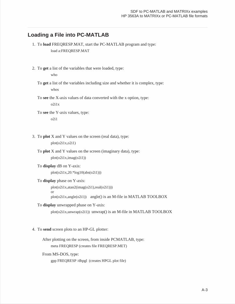
Loading a File into PC-MATLAB
1. To load FREQRESP.MAT, start the PC-MATLAB program and type:
load a:FREQRESP.MAT
2. Toget a list of the variables that were loaded, type:
who
To geta list of the variables including size and whether it is complex, type:
whos
To seethe X-axis values of data converted with the x option, type:
o2i1x
To seethe Y-axis values, type:
o2i1
3. Toplot X and Y values on the screen (real data), type:
plot(o2i1x,o2i1)
To plot X and Y values on the screen (imaginary data), type:
plot(o2i1x,imag(o2i1))
To display dB on Y-axis:
plot(o2i1x,20.*log10(abs(o2i1)))
To display phase on Y-axis:
plot(o2i1x,atan2(imag(o2i1),real(o2i1)))orplot(o2i1x,angle(o2i1)) angle() is an M-file in MATLAB TOOLBOX
To display unwrapped phase on Y-axis:
plot(o2i1x,unwrap(o2i1))unwrap() is an M-file in MATLAB TOOLBOX
4. Tosendscreen plots to an HP-GL plotter:
After plotting on the screen, from inside PCMATLAB, type:
meta FREQRESP (creates file FREQRESP.MET)
From MS-DOS, type:
gpp FREQRESP /dhpgl (creates HPGL plot file)
SDF to PC-MATLAB and MATRIXx examplesHP 3563A to MATRIXx or PC-MATLAB file formats
A-3
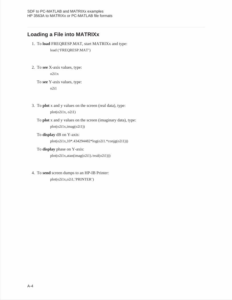
Loading a File into MATRIXx
1. To load FREQRESP.MAT, start MATRIXx and type:
load (‘FREQRESP.MAT’)
2. ToseeX-axis values, type:
o2i1x
To seeY-axis values, type:
o2i1
3. Toplot x and y values on the screen (real data), type:
plot(o2i1x, o2i1)
To plot x and y values on the screen (imaginary data), type:
plot(o2i1x,imag(o2i1))
To display dB on Y-axis:
plot(o2i1x,10*.434294482*log(o2i1.*conjg(o2i1)))
To display phase on Y-axis:
plot(o2i1x,atan(imag(o2i1)./real(o2i1)))
4. Tosendscreen dumps to an HP-IB Printer:
plot(o2i1x,o2i1,’PRINTER’)
SDF to PC-MATLAB and MATRIXx examplesHP 3563A to MATRIXx or PC-MATLAB file formats
A-4
B
Standard Data Format (SDF)
This appendix describes the organization of files that use the Standard Data Format (SDF). SDF filescontain both measurement data and the settings of important instrument parameters when the data wastaken.
For more information on SDF data see chapter 2 and chapter 6.
B-1
Records—the Basic SDF Units
An SDF file consists of a number of smaller units called records: one “master,” called the File Header,followed by a variable number of additional records. A record contains a group of related parameters anddata. For example, a record called the Channel Header contains all channel-specific information for oneof the channels used in a measurement.
There are eleven common records defined for SDF files:
File Header: Provides an index to the file.
MeasurementHeader:
Contains settings of measurement parameters.
Data Header: Tells you how reconstruct one block of measurement results (x- and y-axisvalues for every point of every trace).
Vector Header: Tells you which channel (or pair of channels) provided data for a single trace.
Channel Header: Contains channel-specific information for one channel used in the measurement.
Scan Structure: Tells you how vectors are organized in the Y-axis Data record when themeasurement includes multiple scans of data.
Scan Big: Extended scan header which tells how vectors are organized in the Y-axis datarecord when the measurement may include more than 32767 scans of data.
Scan Variable: Contains a number that identifies every scan (scan time, RPM, or scan number).
Comment Header: Contains text information associated with the file.
X-axis Data: Contains the x-axis data needed to reconstruct any trace.
Y-axis Data: Contains the y-axis data needed to reconstruct any trace.
Another record—the Unique record—makes the SDF file format flexible. The eight common recordtypes define parameters that are common to many instruments and systems. However, a particularinstrument or system may need to save and recall the states of additional parameters. These states canreside in Unique records.
Standard Data Format (SDF)
B-2
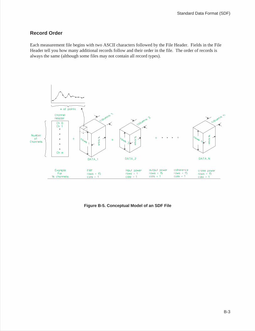
Record Order
Each measurement file begins with two ASCII characters followed by the File Header. Fields in the FileHeader tell you how many additional records follow and their order in the file. The order of records isalways the same (although some files may not contain all record types).
Figure B-5. Conceptual Model of an SDF File
Standard Data Format (SDF)
B-3
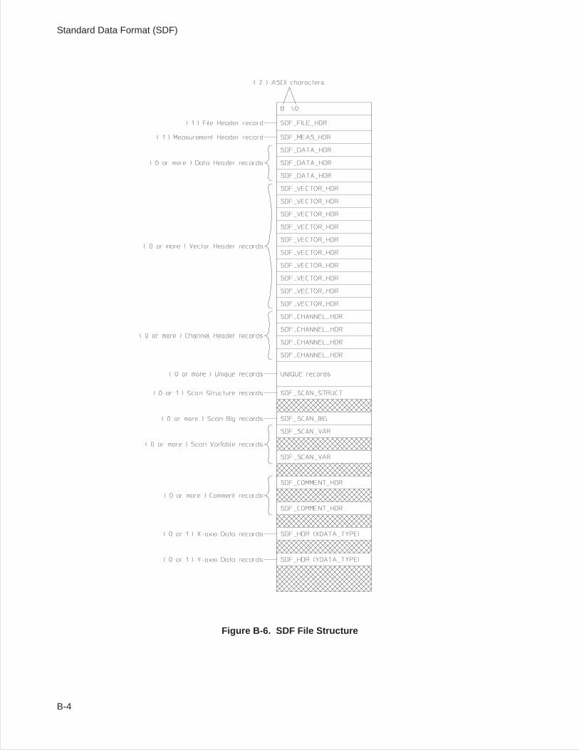
Figure B-6. SDF File Structure
Standard Data Format (SDF)
B-4
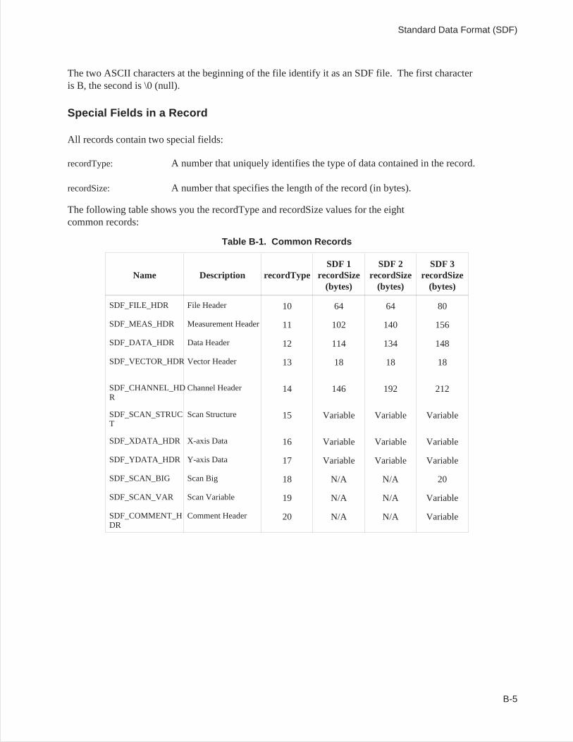
The two ASCII characters at the beginning of the file identify it as an SDF file. The first characteris B, the second is \0 (null).
Special Fields in a Record
All records contain two special fields:
recordType: A number that uniquely identifies the type of data contained in the record.
recordSize: A number that specifies the length of the record (in bytes).
The following table shows you the recordType and recordSize values for the eightcommon records:
Table B-1. Common Records
Name Description recordTypeSDF 1
recordSize(bytes)
SDF 2recordSize
(bytes)
SDF 3recordSize
(bytes)
SDF_FILE_HDR File Header 10 64 64 80
SDF_MEAS_HDR Measurement Header 11 102 140 156
SDF_DATA_HDR Data Header 12 114 134 148
SDF_VECTOR_HDR Vector Header 13 18 18 18
SDF_CHANNEL_HDR
Channel Header 14 146 192 212
SDF_SCAN_STRUCT
Scan Structure 15 Variable Variable Variable
SDF_XDATA_HDR X-axis Data 16 Variable Variable Variable
SDF_YDATA_HDR Y-axis Data 17 Variable Variable Variable
SDF_SCAN_BIG Scan Big 18 N/A N/A 20
SDF_SCAN_VAR Scan Variable 19 N/A N/A Variable
SDF_COMMENT_HDR
Comment Header 20 N/A N/A Variable
Standard Data Format (SDF)
B-5
Record and Structure Descriptions
The following tables describes the individual records and structures from which the SDF files are built.Each table includes:
• A field index.• A binary index.• A description of each field.• A description of the data type used in each field.• The range of values for data in the field.
The fields in SDF records and structures use the following data types:
Char[n]: This data type consists of a series of ASCII-encoded bytes. [n] specifies thenumber of bytes in the field.
Short: This data type is used for integers (maximum range is−32768 to +32767).Values are transferred as two-byte, binary encoded integers.
Long: This data type is also used for integers (but the maximum range is−2,147,483,648 to +2,147,483,647). Values are stored as four-byte,binary-encoded integers.
Float: This data type is used for single-precision fixed-point and floating-pointnumbers. Values are stored in the 32-bit binary floating-point format.
Double: This data type is used for double-precision fixed-point and floating-pointnumbers. Values are stored using the 64-bit binary floating-point format.
Standard Data Format (SDF)
B-6
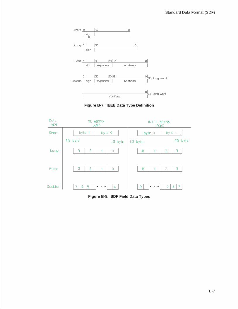
Figure B-7. IEEE Data Type Definition
Figure B-8. SDF Field Data Types
Standard Data Format (SDF)
B-7
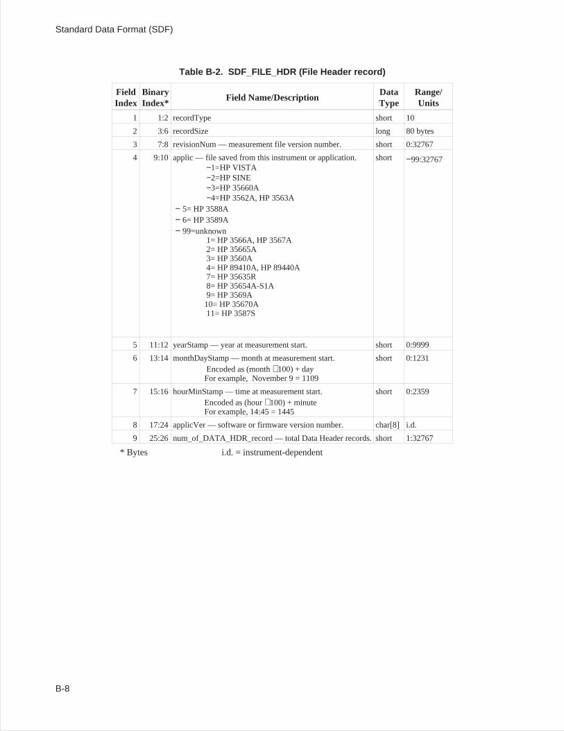
Table B-2. SDF_FILE_HDR (File Header record)
FieldIndex
BinaryIndex*
Field Name/DescriptionDataType
Range/Units
1 1:2 recordType short 10
2 3:6 recordSize long 80 bytes
3 7:8 revisionNum — measurement file version number. short 0:32767
4 9:10 applic — file saved from this instrument or application.−1=HP VISTA−2=HP SINE−3=HP 35660A−4=HP 3562A, HP 3563A
− 5= HP 3588A− 6= HP 3589A− 99=unknown
1= HP 3566A, HP 3567A2= HP 35665A3= HP 3560A4= HP 89410A, HP 89440A7= HP 35635R8= HP 35654A-S1A9= HP 3569A10= HP 35670A11= HP 3587S
short −99:32767
5 11:12 yearStamp — year at measurement start. short 0:9999
6 13:14 monthDayStamp — month at measurement start.Encoded as (month 100) + dayFor example, November 9 = 1109
short 0:1231
7 15:16 hourMinStamp — time at measurement start.Encoded as (hour 100) + minuteFor example, 14:45 = 1445
short 0:2359
8 17:24 applicVer — software or firmware version number. char[8] i.d.
9 25:26 num_of_DATA_HDR_record — total Data Header records. short 1:32767
* Bytes i.d. = instrument-dependent
Standard Data Format (SDF)
B-8
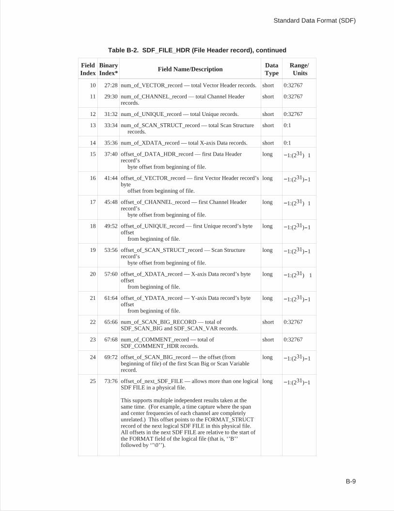
Table B-2. SDF_FILE_HDR (File Header record), continued
FieldIndex
BinaryIndex*
Field Name/DescriptionDataType
Range/Units
10 27:28 num_of_VECTOR_record — total Vector Header records. short 0:32767
11 29:30 num_of_CHANNEL_record — total Channel Headerrecords.
short 0:32767
12 31:32 num_of_UNIQUE_record — total Unique records. short 0:32767
13 33:34 num_of_SCAN_STRUCT_record — total Scan Structurerecords.
short 0:1
14 35:36 num_of_XDATA_record — total X-axis Data records. short 0:1
15 37:40 offset_of_DATA_HDR_record — first Data Headerrecord’s
byte offset from beginning of file.
long −1:(231)-1
16 41:44 offset_of_VECTOR_record — first Vector Header record’sbyte
offset from beginning of file.
long −1:(231)-1
17 45:48 offset_of_CHANNEL_record — first Channel Headerrecord’s
byte offset from beginning of file.
long −1:(231)-1
18 49:52 offset_of_UNIQUE_record — first Unique record’s byteoffset
from beginning of file.
long −1:(231)-1
19 53:56 offset_of_SCAN_STRUCT_record — Scan Structurerecord’s
byte offset from beginning of file.
long −1:(231)-1
20 57:60 offset_of_XDATA_record — X-axis Data record’s byteoffset
from beginning of file.
long −1:(231) -1
21 61:64 offset_of_YDATA_record — Y-axis Data record’s byteoffset
from beginning of file.
long −1:(231)-1
22 65:66 num_of_SCAN_BIG_RECORD — total ofSDF_SCAN_BIG and SDF_SCAN_VAR records.
short 0:32767
23 67:68 num_of_COMMENT_record — total ofSDF_COMMENT_HDR records.
short 0:32767
24 69:72 offset_of_SCAN_BIG_record — the offset (frombeginning of file) of the first Scan Big or Scan Variablerecord.
long −1:(231)-1
25 73:76 offset_of_next_SDF_FILE — allows more than one logicalSDF FILE in a physical file.
This supports multiple independent results taken at thesame time. (For example, a time capture where the spanand center frequencies of each channel are completelyunrelated.) This offset points to the FORMAT_STRUCTrecord of the next logical SDF FILE in this physical file.All offsets in the next SDF FILE are relative to the start ofthe FORMAT field of the logical file (that is, ‘’B’’followed by ‘’\0’’).
long −1:(231)−1
Standard Data Format (SDF)
B-9

* Bytes i.d. = instrument-dependent
Standard Data Format (SDF)
B-10
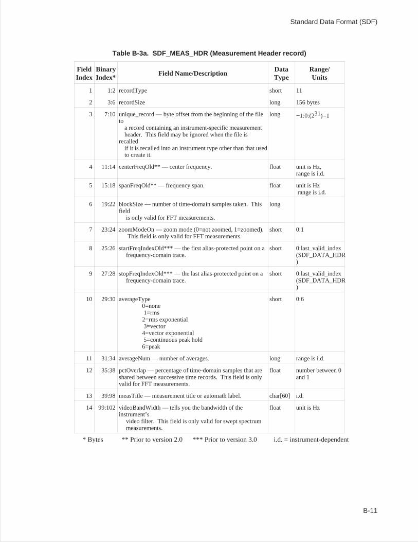
Table B-3a. SDF_MEAS_HDR (Measurement Header record)
FieldIndex
BinaryIndex*
Field Name/DescriptionDataType
Range/Units
1 1:2 recordType short 11
2 3:6 recordSize long 156 bytes
3 7:10 unique_record — byte offset from the beginning of the fileto
a record containing an instrument-specific measurementheader. This field may be ignored when the file is
recalledif it is recalled into an instrument type other than that usedto create it.
long −1:0:(231)-1
4 11:14 centerFreqOld** — center frequency. float unit is Hz,range is i.d.
5 15:18 spanFreqOld** — frequency span. float unit is Hzrange is i.d.
6 19:22 blockSize — number of time-domain samples taken. Thisfield
is only valid for FFT measurements.
long
7 23:24 zoomModeOn — zoom mode (0=not zoomed, 1=zoomed).This field is only valid for FFT measurements.
short 0:1
8 25:26 startFreqIndexOld*** — the first alias-protected point on afrequency-domain trace.
short 0:last_valid_index(SDF_DATA_HDR)
9 27:28 stopFreqIndexOld*** — the last alias-protected point on afrequency-domain trace.
short 0:last_valid_index(SDF_DATA_HDR)
10 29:30 averageType0=none1=rms2=rms exponential3=vector4=vector exponential5=continuous peak hold6=peak
short 0:6
11 31:34 averageNum — number of averages. long range is i.d.
12 35:38 pctOverlap — percentage of time-domain samples that areshared between successive time records. This field is onlyvalid for FFT measurements.
float number between 0and 1
13 39:98 measTitle — measurement title or automath label. char[60] i.d.
14 99:102 videoBandWidth — tells you the bandwidth of theinstrument’s
video filter. This field is only valid for swept spectrummeasurements.
float unit is Hz
* Bytes ** Prior to version 2.0 *** Prior to version 3.0 i.d. = instrument-dependent
Standard Data Format (SDF)
B-11
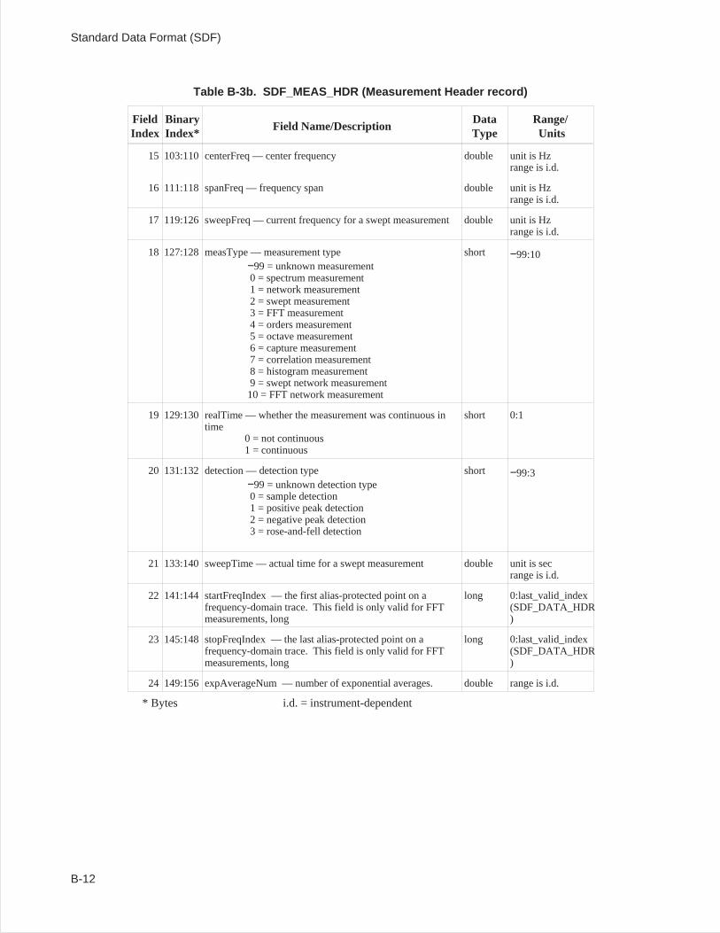
Table B-3b. SDF_MEAS_HDR (Measurement Header record)
FieldIndex
BinaryIndex*
Field Name/DescriptionDataType
Range/Units
15 103:110 centerFreq — center frequency double unit is Hzrange is i.d.
16 111:118 spanFreq — frequency span double unit is Hzrange is i.d.
17 119:126 sweepFreq — current frequency for a swept measurement double unit is Hzrange is i.d.
18 127:128 measType — measurement type−99 = unknown measurement0 = spectrum measurement1 = network measurement2 = swept measurement3 = FFT measurement4 = orders measurement5 = octave measurement6 = capture measurement7 = correlation measurement8 = histogram measurement9 = swept network measurement10 = FFT network measurement
short −99:10
19 129:130 realTime — whether the measurement was continuous intime
0 = not continuous1 = continuous
short 0:1
20 131:132 detection — detection type−99 = unknown detection type0 = sample detection1 = positive peak detection2 = negative peak detection3 = rose-and-fell detection
short −99:3
21 133:140 sweepTime — actual time for a swept measurement double unit is secrange is i.d.
22 141:144 startFreqIndex — the first alias-protected point on afrequency-domain trace. This field is only valid for FFTmeasurements, long
long 0:last_valid_index(SDF_DATA_HDR)
23 145:148stopFreqIndex — the last alias-protected point on afrequency-domain trace. This field is only valid for FFTmeasurements, long
long 0:last_valid_index(SDF_DATA_HDR)
24 149:156 expAverageNum — number of exponential averages. double range is i.d.
* Bytes i.d. = instrument-dependent
Standard Data Format (SDF)
B-12
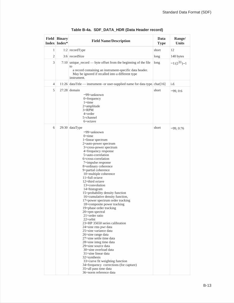
Table B-4a. SDF_DATA_HDR (Data Header record)
FieldIndex
BinaryIndex*
Field Name/DescriptionDataType
Range/Units
1 1:2 recordType short 12
2 3:6 recordSize long 148 bytes
3 7:10 unique_record — byte offset from the beginning of the fileto
a record containing an instrument-specific data header.May be ignored if recalled into a different type
instrument.
long −1:(231)-1
4 11:26 dataTitle — instrument- or user-supplied name for data type. char[16] i.d.
5 27:28 domain−99=unknown0=frequency1=time2=amplitude3=RPM4=order5=channel6=octave
short −99, 0:6
6 29:30 dataType−99=unknown0=time1=linear spectrum2=auto-power spectrum3=cross-power spectrum4=frequency response5=auto-correlation6=cross-correlation7=impulse response8=ordinary coherence9=partial coherence10=multiple coherence11=full octave12=third octave13=convolution14=histogram15=probability density function16=cumulative density function,17=power spectrum order tracking18=composite power tracking19=phase order tracking20=rpm spectral21=order ratio22=orbit23=HP 35650 series calibration24=sine rms pwr data25=sine variance data26=sine range data27=sine settle time data28=sine integ time data29=sine source data30=sine overload data31=sine linear data32=synthesis33=curve fit weighting function34=frequency corrections (for capture)35=all pass time data36=norm reference data
short −99, 0:76
Standard Data Format (SDF)
B-13
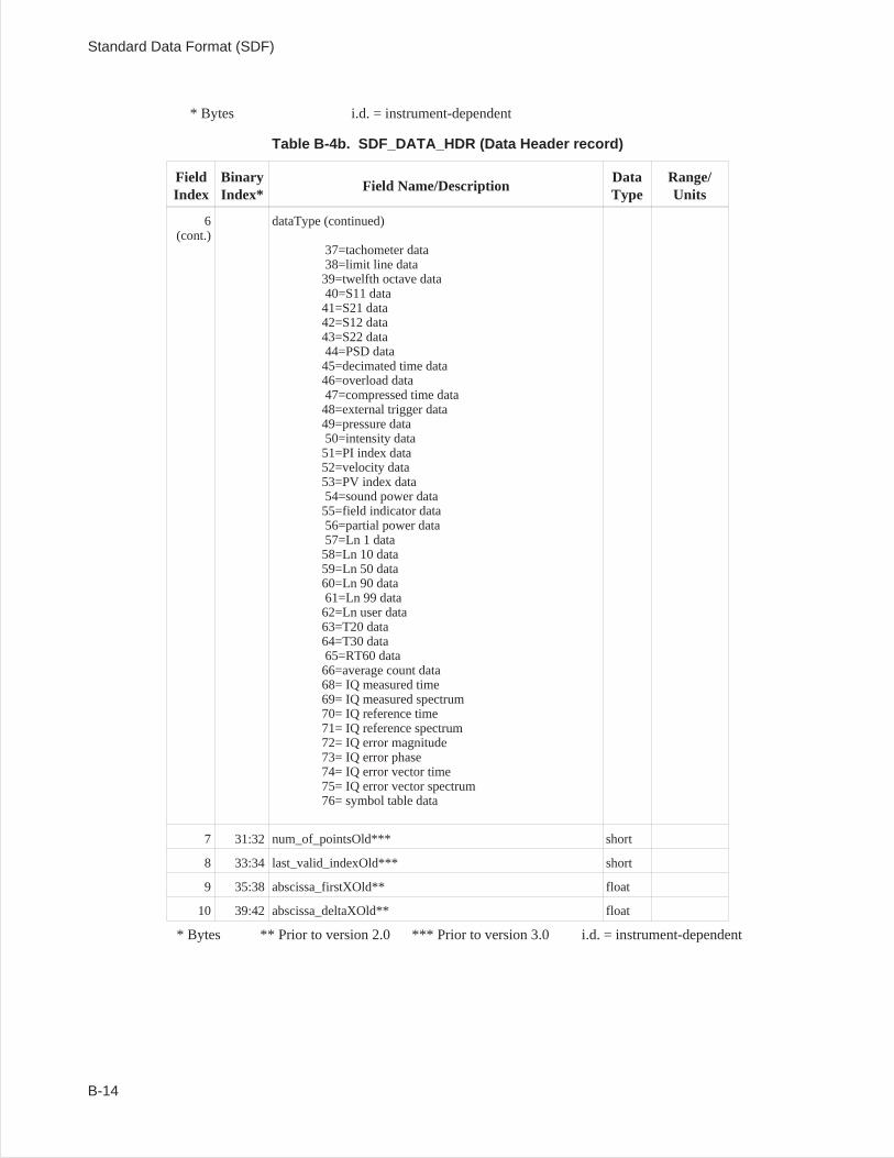
* Bytes i.d. = instrument-dependent
Table B-4b. SDF_DATA_HDR (Data Header record)
FieldIndex
BinaryIndex*
Field Name/DescriptionDataType
Range/Units
6(cont.)
dataType (continued)
37=tachometer data38=limit line data39=twelfth octave data40=S11 data41=S21 data42=S12 data43=S22 data44=PSD data45=decimated time data46=overload data47=compressed time data48=external trigger data49=pressure data50=intensity data51=PI index data52=velocity data53=PV index data54=sound power data55=field indicator data56=partial power data57=Ln 1 data58=Ln 10 data59=Ln 50 data60=Ln 90 data61=Ln 99 data62=Ln user data63=T20 data64=T30 data65=RT60 data66=average count data68= IQ measured time69= IQ measured spectrum70= IQ reference time71= IQ reference spectrum72= IQ error magnitude73= IQ error phase74= IQ error vector time75= IQ error vector spectrum76= symbol table data
7 31:32 num_of_pointsOld*** short
8 33:34 last_valid_indexOld*** short
9 35:38 abscissa_firstXOld** float
10 39:42 abscissa_deltaXOld** float
* Bytes ** Prior to version 2.0 *** Prior to version 3.0 i.d. = instrument-dependent
Standard Data Format (SDF)
B-14
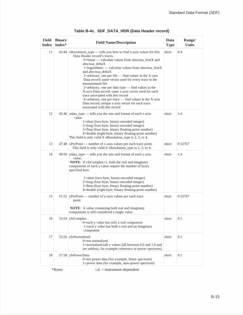
Table B-4c. SDF_DATA_HDR (Data Header record)
FieldIndex
BinaryIndex*
Field Name/DescriptionDataType
Range/Units
11 43:44 xResolution_type — tells you how to find x-axis values for thisData Header record’s traces.
0=linear — calculate values from abscissa_firstX andabscissa_deltaX1=logarithmic — calculate values from abscissa_firstXand abscissa_deltaX2=arbitrary, one per file — find values in the X-axisData record; same vector used for every trace in themeasurement file3=arbitrary, one per data type — find values in theX-axis Data record; same x-axis vector used for eachtrace associated with this record4=arbitrary, one per trace — find values in the X-axisData record; unique x-axis vector for each traceassociated with this record
short 0:4
12 45:46 xdata_type — tells you the size and format of each x-axisvalue.
1=short (two-byte, binary-encoded integer)2=long (four-byte, binary-encoded integer)3=float (four-byte, binary floating-point number)4=double (eight-byte, binary floating-point number)
This field is only valid if xResolution_type is 2, 3, or 4.
short 1:4
13 47:48 xPerPoint — number of x-axis values per each trace point.This field is only valid if xResolution_type is 2, 3, or 4.
short 0:32767
14 49:50 ydata_type — tells you the size and format of each y-axisvalue.
NOTE: If yIsComplex=1, both the real and imaginarycomponents of each y value require the number of bytesspecified here.
1=short (two-byte, binary-encoded integer)2=long (four-byte, binary-encoded integer)3=float (four-byte, binary floating-point number)4=double (eight-byte, binary floating-point number)
short 1:4
15 51:52 yPerPoint — number of y-axis values per each tracepoint.
NOTE: A value containing both real and imaginarycomponents is still considered a single value.
short 0:32767
16 53:54 yIsComplex0=each y value has only a real component1=each y value has both a real and an imaginarycomponent
short 0:1
17 55:56 yIsNormalized0=not normalized1=normalized (all y values fall between 0.0 and 1.0 andare unitless, for example coherence or power spectrum).
short 0:1
18 57:58 yIsPowerData0=not power data (for example, linear spectrum)1=power data (for example, auto-power spectrum)
short 0:1
*Bytes i.d. = instrument-dependent
Standard Data Format (SDF)
B-15
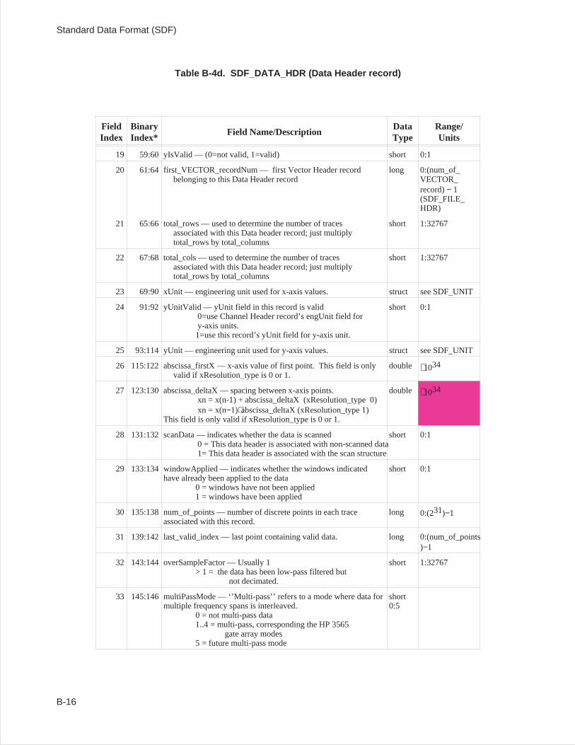
Table B-4d. SDF_DATA_HDR (Data Header record)
FieldIndex
BinaryIndex*
Field Name/DescriptionDataType
Range/Units
19 59:60 yIsValid — (0=not valid, 1=valid) short 0:1
20 61:64 first_VECTOR_recordNum — first Vector Header recordbelonging to this Data Header record
long 0:(num_of_VECTOR_record)− 1(SDF_FILE_HDR)
21 65:66 total_rows — used to determine the number of tracesassociated with this Data header record; just multiplytotal_rows by total_columns
short 1:32767
22 67:68 total_cols — used to determine the number of tracesassociated with this Data header record; just multiplytotal_rows by total_columns
short 1:32767
23 69:90 xUnit — engineering unit used for x-axis values. struct see SDF_UNIT
24 91:92 yUnitValid — yUnit field in this record is valid0=use Channel Header record’s engUnit field fory-axis units.1=use this record’s yUnit field for y-axis unit.
short 0:1
25 93:114 yUnit — engineering unit used for y-axis values. struct see SDF_UNIT
26 115:122 abscissa_firstX — x-axis value of first point. This field is onlyvalid if xResolution_type is 0 or 1.
double 1034
27 123:130 abscissa_deltaX — spacing between x-axis points.xn = x(n-1) + abscissa_deltaX (xResolution_type 0)xn = x(n−1)abscissa_deltaX (xResolution_type 1)
This field is only valid if xResolution_type is 0 or 1.
double 1034
28 131:132 scanData — indicates whether the data is scanned0 = This data header is associated with non-scanned data1= This data header is associated with the scan structure
short 0:1
29 133:134 windowApplied — indicates whether the windows indicatedhave already been applied to the data
0 = windows have not been applied1 = windows have been applied
short 0:1
30 135:138 num_of_points — number of discrete points in each traceassociated with this record.
long 0:(231)−1
31 139:142last_valid_index — last point containing valid data. long 0:(num_of_points)−1
32 143:144 overSampleFactor — Usually 1> 1 = the data has been low-pass filtered but
not decimated.
short 1:32767
33 145:146 multiPassMode — ‘’Multi-pass’’ refers to a mode where data formultiple frequency spans is interleaved.
0 = not multi-pass data1..4 = multi-pass, corresponding the HP 3565
gate array modes5 = future multi-pass mode
short0:5
Standard Data Format (SDF)
B-16
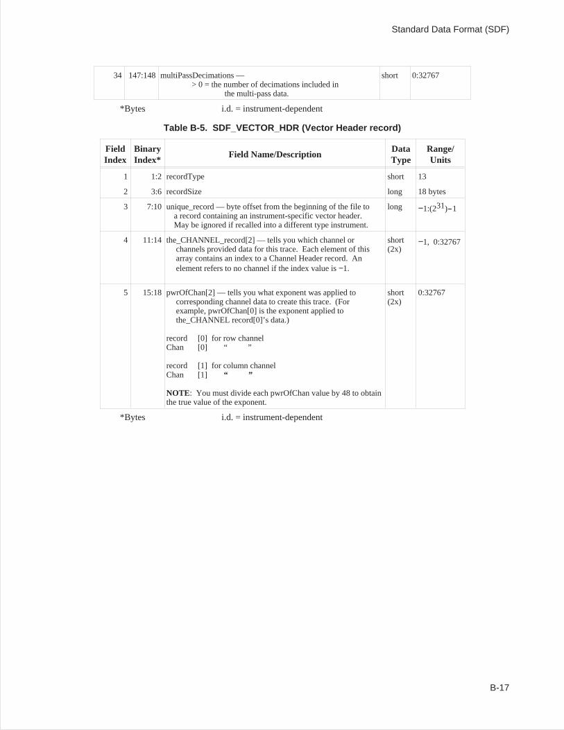
34 147:148 multiPassDecimations —> 0 = the number of decimations included in
the multi-pass data.
short 0:32767
*Bytes i.d. = instrument-dependent
Table B-5. SDF_VECTOR_HDR (Vector Header record)
FieldIndex
BinaryIndex*
Field Name/DescriptionDataType
Range/Units
1 1:2 recordType short 13
2 3:6 recordSize long 18 bytes
3 7:10 unique_record — byte offset from the beginning of the file toa record containing an instrument-specific vector header.May be ignored if recalled into a different type instrument.
long −1:(231)-1
4 11:14 the_CHANNEL_record[2] — tells you which channel orchannels provided data for this trace. Each element of thisarray contains an index to a Channel Header record. Anelement refers to no channel if the index value is−1.
short(2x)
−1, 0:32767
5 15:18 pwrOfChan[2] — tells you what exponent was applied tocorresponding channel data to create this trace. (Forexample, pwrOfChan[0] is the exponent applied tothe_CHANNEL record[0]’s data.)
record [0] for row channelChan [0] “ ”
record [1] for column channelChan [1] “ ”
NOTE: You must divide each pwrOfChan value by 48 to obtainthe true value of the exponent.
short(2x)
0:32767
*Bytes i.d. = instrument-dependent
Standard Data Format (SDF)
B-17
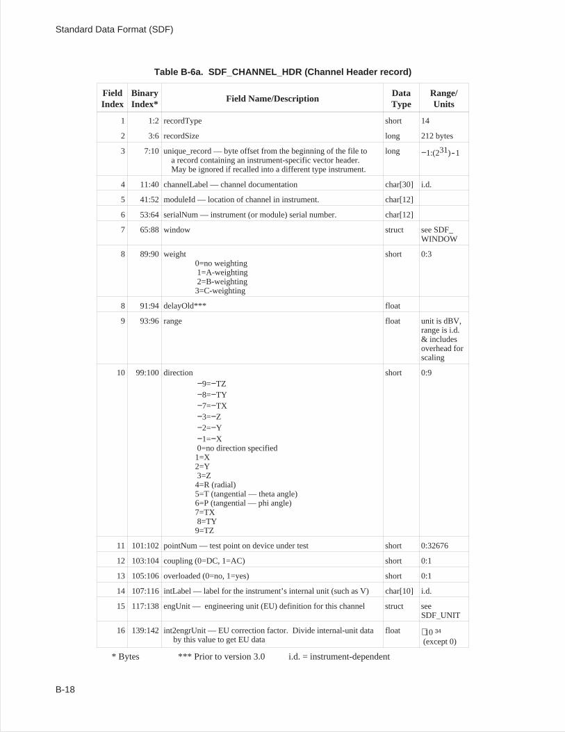
Table B-6a. SDF_CHANNEL_HDR (Channel Header record)
FieldIndex
BinaryIndex*
Field Name/DescriptionDataType
Range/Units
1 1:2 recordType short 14
2 3:6 recordSize long 212 bytes
3 7:10 unique_record — byte offset from the beginning of the file toa record containing an instrument-specific vector header.May be ignored if recalled into a different type instrument.
long −1:(231)-1
4 11:40 channelLabel — channel documentation char[30] i.d.
5 41:52 moduleId — location of channel in instrument. char[12]
6 53:64 serialNum — instrument (or module) serial number. char[12]
7 65:88 window struct see SDF_WINDOW
8 89:90 weight0=no weighting1=A-weighting2=B-weighting3=C-weighting
short 0:3
8 91:94 delayOld*** float
9 93:96 range float unit is dBV,range is i.d.& includesoverhead forscaling
10 99:100 direction−9=−TZ−8=−TY−7=−TX−3=−Z−2=−Y−1=−X0=no direction specified1=X2=Y3=Z4=R (radial)5=T (tangential — theta angle)6=P (tangential — phi angle)7=TX8=TY9=TZ
short 0:9
11 101:102 pointNum — test point on device under test short 0:32676
12 103:104 coupling (0=DC, 1=AC) short 0:1
13 105:106 overloaded (0=no, 1=yes) short 0:1
14 107:116 intLabel — label for the instrument’s internal unit (such as V) char[10] i.d.
15 117:138 engUnit — engineering unit (EU) definition for this channel struct seeSDF_UNIT
16 139:142 int2engrUnit — EU correction factor. Divide internal-unit databy this value to get EU data
float 10 34
(except 0)
* Bytes *** Prior to version 3.0 i.d. = instrument-dependent
Standard Data Format (SDF)
B-18

Standard Data Format (SDF)
B-19
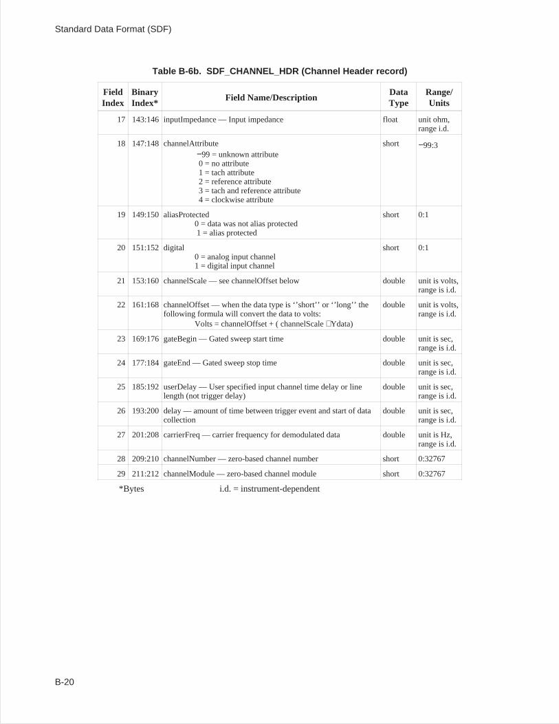
Table B-6b. SDF_CHANNEL_HDR (Channel Header record)
FieldIndex
BinaryIndex*
Field Name/DescriptionDataType
Range/Units
17 143:146 inputImpedance — Input impedance float unit ohm,range i.d.
18 147:148channelAttribute−99 = unknown attribute0 = no attribute1 = tach attribute2 = reference attribute3 = tach and reference attribute4 = clockwise attribute
short −99:3
19 149:150 aliasProtected0 = data was not alias protected1 = alias protected
short 0:1
20 151:152 digital0 = analog input channel1 = digital input channel
short 0:1
21 153:160 channelScale — see channelOffset below double unit is volts,range is i.d.
22 161:168 channelOffset — when the data type is ‘’short’’ or ‘’long’’ thefollowing formula will convert the data to volts:
Volts = channelOffset + ( channelScale Ydata)
double unit is volts,range is i.d.
23 169:176 gateBegin — Gated sweep start time double unit is sec,range is i.d.
24 177:184gateEnd — Gated sweep stop time double unit is sec,range is i.d.
25 185:192 userDelay — User specified input channel time delay or linelength (not trigger delay)
double unit is sec,range is i.d.
26 193:200delay — amount of time between trigger event and start of datacollection
double unit is sec,range is i.d.
27 201:208 carrierFreq — carrier frequency for demodulated data double unit is Hz,range is i.d.
28 209:210channelNumber — zero-based channel number short 0:32767
29 211:212 channelModule — zero-based channel module short 0:32767
*Bytes i.d. = instrument-dependent
Standard Data Format (SDF)
B-20
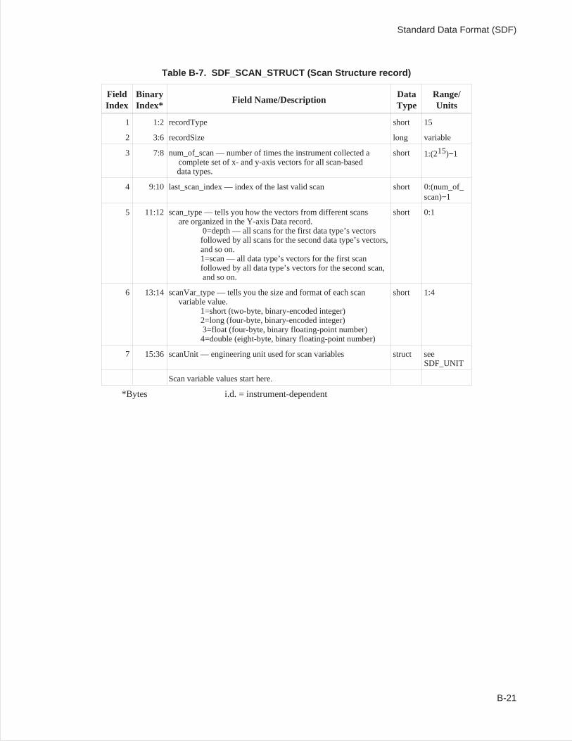
Table B-7. SDF_SCAN_STRUCT (Scan Structure record)
FieldIndex
BinaryIndex*
Field Name/DescriptionDataType
Range/Units
1 1:2 recordType short 15
2 3:6 recordSize long variable
3 7:8 num_of_scan — number of times the instrument collected acomplete set of x- and y-axis vectors for all scan-baseddata types.
short 1:(215)−1
4 9:10 last_scan_index — index of the last valid scan short 0:(num_of_scan)−1
5 11:12 scan_type — tells you how the vectors from different scansare organized in the Y-axis Data record.
0=depth — all scans for the first data type’s vectorsfollowed by all scans for the second data type’s vectors,and so on.1=scan — all data type’s vectors for the first scanfollowed by all data type’s vectors for the second scan,and so on.
short 0:1
6 13:14 scanVar_type — tells you the size and format of each scanvariable value.
1=short (two-byte, binary-encoded integer)2=long (four-byte, binary-encoded integer)3=float (four-byte, binary floating-point number)4=double (eight-byte, binary floating-point number)
short 1:4
7 15:36 scanUnit — engineering unit used for scan variables struct seeSDF_UNIT
Scan variable values start here.
*Bytes i.d. = instrument-dependent
Standard Data Format (SDF)
B-21
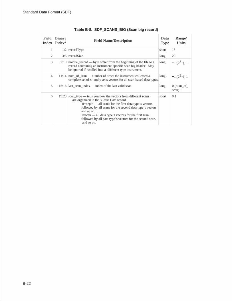
Table B-8. SDF_SCANS_BIG (Scan big record)
FieldIndex
BinaryIndex*
Field Name/DescriptionDataType
Range/Units
1 1:2 recordType short 18
2 3:6 recordSize long 20
3 7:10 unique_record — byte offset from the beginning of the file to arecord containing an instrument-specific scan big header. Maybe ignored if recalled into a different type instrument.
long −1:(231)-1
4 11:14 num_of_scan — number of times the instrument collected acomplete set of x- and y-axis vectors for all scan-based data types.
long −1:(231)-1
5 15:18 last_scan_index — index of the last valid scan. long 0:(num_of_scan)−1
6 19:20 scan_type — tells you how the vectors from different scansare organized in the Y-axis Data record.
0=depth — all scans for the first data type’s vectorsfollowed by all scans for the second data type’s vectors,and so on.1=scan — all data type’s vectors for the first scanfollowed by all data type’s vectors for the second scan,and so on.
short 0:1
Standard Data Format (SDF)
B-22
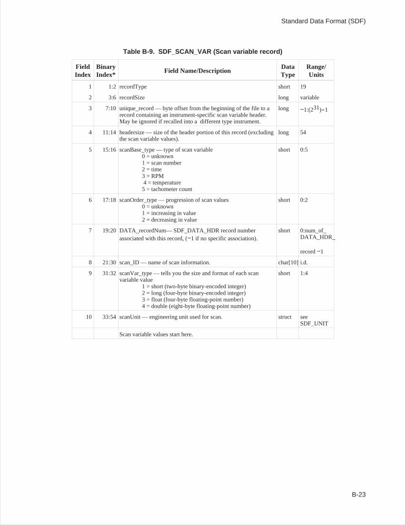
Table B-9. SDF_SCAN_VAR (Scan variable record)
FieldIndex
BinaryIndex*
Field Name/DescriptionDataType
Range/Units
1 1:2 recordType short 19
2 3:6 recordSize long variable
3 7:10 unique_record — byte offset from the beginning of the file to arecord containing an instrument-specific scan variable header.May be ignored if recalled into a different type instrument.
long −1:(231)-1
4 11:14 headersize — size of the header portion of this record (excludingthe scan variable values).
long 54
5 15:16 scanBase_type — type of scan variable0 = unknown1 = scan number2 = time3 = RPM4 = temperature5 = tachometer count
short 0:5
6 17:18 scanOrder_type — progression of scan values0 = unknown1 = increasing in value2 = decreasing in value
short 0:2
7 19:20 DATA_recordNum— SDF_DATA_HDR record numberassociated with this record, (−1 if no specific association).
short 0:num_of_DATA_HDR_
record−1
8 21:30 scan_ID — name of scan information. char[10] i.d.
9 31:32 scanVar_type — tells you the size and format of each scanvariable value
1 = short (two-byte binary-encoded integer)2 = long (four-byte binary-encoded integer)3 = float (four-byte floating-point number)4 = double (eight-byte floating-point number)
short 1:4
10 33:54 scanUnit — engineering unit used for scan. struct seeSDF_UNIT
Scan variable values start here.
Standard Data Format (SDF)
B-23
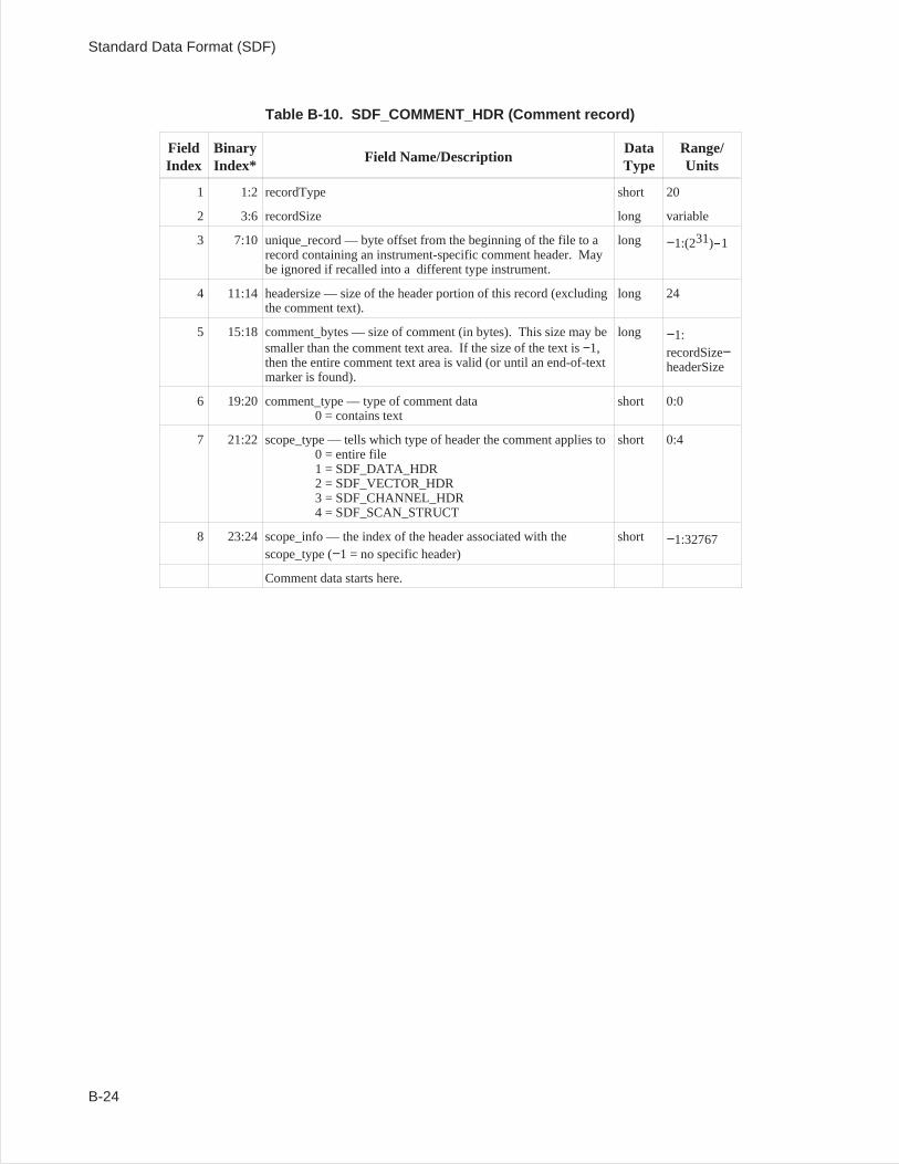
Table B-10. SDF_COMMENT_HDR (Comment record)
FieldIndex
BinaryIndex*
Field Name/DescriptionDataType
Range/Units
1 1:2 recordType short 20
2 3:6 recordSize long variable
3 7:10 unique_record — byte offset from the beginning of the file to arecord containing an instrument-specific comment header. Maybe ignored if recalled into a different type instrument.
long −1:(231)-1
4 11:14 headersize — size of the header portion of this record (excludingthe comment text).
long 24
5 15:18 comment_bytes — size of comment (in bytes). This size may besmaller than the comment text area. If the size of the text is−1,then the entire comment text area is valid (or until an end-of-textmarker is found).
long −1:recordSize−headerSize
6 19:20 comment_type — type of comment data0 = contains text
short 0:0
7 21:22 scope_type — tells which type of header the comment applies to0 = entire file1 = SDF_DATA_HDR2 = SDF_VECTOR_HDR3 = SDF_CHANNEL_HDR4 = SDF_SCAN_STRUCT
short 0:4
8 23:24 scope_info — the index of the header associated with thescope_type (−1 = no specific header)
short −1:32767
Comment data starts here.
Standard Data Format (SDF)
B-24

Table B-11. SDF_XDATA_HDR (X-axis Data record)
FieldIndex
BinaryIndex*
Field Name/DescriptionDataType
Range/Units
1 1:2 recordType short 16
2 3:6 recordSize long Variable
X data values start here.
*Bytes
Table B-12. SDF_YDATA_HDR (Y-axis Data record)
FieldIndex
BinaryIndex*
Field Name/DescriptionDataType
Range/Units
1 1:2 recordType short 17
2 3:6 recordSize long Variable
Y data values start here.
*Bytes
Table B-13. SDF_UNIT (Unit structure)
FieldIndex
BinaryIndex*
Field Name/DescriptionDataType
Range/Units
1 1:10 label — engineering unit label (such as g). char[10] i.d.
2 11:14 factor — converts this unit to the equivalent SI unit float 1034
(except 0)
3 15 mass — 2 times the unit exponent for the mass dimension char−128:127
4 16 length — 2 times the unit exponent for the length dimension char −128:127
5 17 time — 2 times the unit exponent for the time dimension char −128:127
6 18 current — 2 times the unit exponent for the current dimension char−128:127
7 19 temperature — 2 times the unit exponent for the temperaturedimension
char −128:127
8 20 luminal_intensity — 2 times the unit exponent for the luminalintensity dimension
char −128:127
9 21 mole — 2 times the unit exponent for the mole dimension char −128:127
10 22 plane_angle — 2 times the unit exponent for the plane angledimension
char −128:127
*Bytes i.d. = instrument-dependent
Standard Data Format (SDF)
B-25
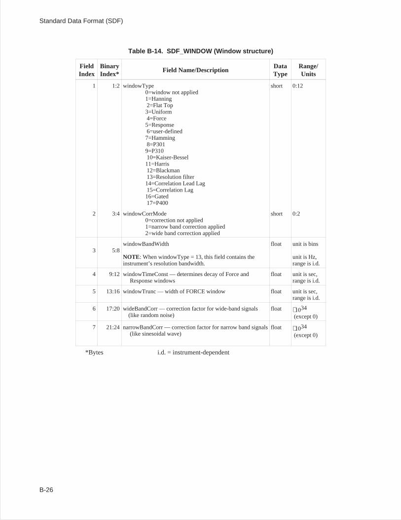
Table B-14. SDF_WINDOW (Window structure)
FieldIndex
BinaryIndex*
Field Name/DescriptionDataType
Range/Units
1 1:2 windowType0=window not applied1=Hanning2=Flat Top3=Uniform4=Force5=Response6=user-defined7=Hamming8=P3019=P31010=Kaiser-Bessel11=Harris12=Blackman13=Resolution filter14=Correlation Lead Lag15=Correlation Lag16=Gated17=P400
short 0:12
2 3:4 windowCorrMode0=correction not applied1=narrow band correction applied2=wide band correction applied
short 0:2
3 5:8windowBandWidth
NOTE: When windowType = 13, this field contains theinstrument’s resolution bandwidth.
float unit is bins
unit is Hz,range is i.d.
4 9:12 windowTimeConst — determines decay of Force andResponse windows
float unit is sec,range is i.d.
5 13:16 windowTrunc — width of FORCE window float unit is sec,range is i.d.
6 17:20 wideBandCorr — correction factor for wide-band signals(like random noise)
float 1034
(except 0)
7 21:24 narrowBandCorr — correction factor for narrow band signals(like sinesoidal wave)
float 1034
(except 0)
*Bytes i.d. = instrument-dependent
Standard Data Format (SDF)
B-26
Reconstructing a Trace
The simplest SDF file defines a single trace. A trace consists of a series of discrete points, each definedby an X-axis value and a Y-axis value. This section tells you how to locate or calculate a single trace’sX-axis and Y-axis values.
X-axis Values
A trace’s X-axis values are stored in one of two SDF records: the Data Header record, or the X-axis Datarecord. The location used depends on whether or not consecutive points are evenly spaced along theX-axis:
Evenly-spaced points: X-axis values are stored in the Data Header record.Unevenly-spaced points: X-axis values are stored in the X-axis Data record.
Field 11 of the Data Header record (xResolution_type) is an indicator of X-axis spacing. Consecutivepoints are evenly spaced if xResolution_type has value of 0 or 1; they are unevenly spaced if it has avalue of 2, 3, or 4.
When consecutive trace points are evenly spaced along the X-axis (xResolution_type = 0, or 1), the SDFfile doesnot include an X-axis Data record. Instead, the X-axis values of these points are completelydefined by three fields in the Data Header record:
abscissa_firstX: tells you the X-axis value of the first point.
abscissa_deltaX: tells you the X-axis spacing between points.
num_of_points: tells you how many discrete points the trace is composed of.
You can calculate X-axis values this way when xResolution_type is 0 (linear resolution):
x0 = abscissa_firstXx1 = x0 + abscissa_deltaXx2 = x0 + abscissa_deltaX * 2x3 = x0 + abscissa_deltaX * 3
...
xn = x0 + abscissa_deltaX * n (where n = num_of_points−1)
Standard Data Format (SDF)
B-27
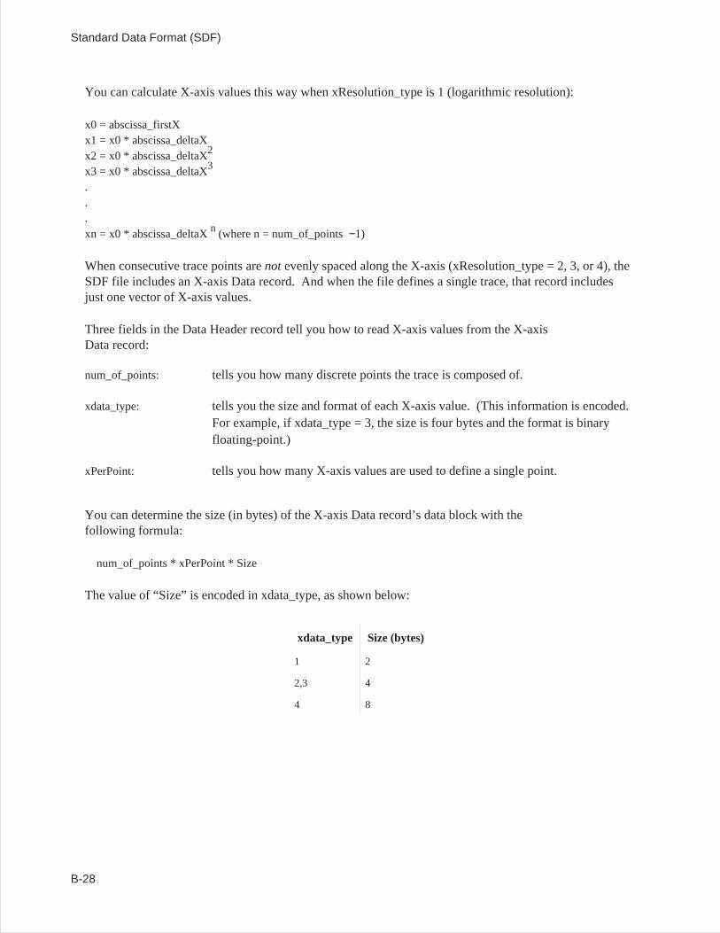
You can calculate X-axis values this way when xResolution_type is 1 (logarithmic resolution):
x0 = abscissa_firstXx1 = x0 * abscissa_deltaXx2 = x0 * abscissa_deltaX2
x3 = x0 * abscissa_deltaX3
.
.
.xn = x0 * abscissa_deltaXn (where n = num_of_points−1)
When consecutive trace points arenotevenly spaced along the X-axis (xResolution_type = 2, 3, or 4), theSDF file includes an X-axis Data record. And when the file defines a single trace, that record includesjust one vector of X-axis values.
Three fields in the Data Header record tell you how to read X-axis values from the X-axisData record:
num_of_points: tells you how many discrete points the trace is composed of.
xdata_type: tells you the size and format of each X-axis value. (This information is encoded.For example, if xdata_type = 3, the size is four bytes and the format is binaryfloating-point.)
xPerPoint: tells you how many X-axis values are used to define a single point.
You can determine the size (in bytes) of the X-axis Data record’s data block with thefollowing formula:
num_of_points * xPerPoint * Size
The value of “Size” is encoded in xdata_type, as shown below:
xdata_type Size (bytes)
1 2
2,3 4
4 8
Standard Data Format (SDF)
B-28
Y-axis Values
A trace’s Y-axis values are always stored in an SDF file’s Y-axis Data record. And when the file definesa single trace, that record includes just one vector of Y-axis values. Reading this vector of values issimilar to reading a vector of X-axis values from the X-axis Data record.
Four fields in the Data Header record tell you how to read Y-axis values from the Y-axis Data record:
num_of_points: tells you how many discrete points the trace is composed of.
ydata_type: tells you the size and format of each Y-axis value. (This information is encoded.For example, if ydata_type = 3, the size is our bytes and the format is binaryfloating-point.)
yPerPoint: tells you how many Y-axis values are used to define a single point.
yIsComplex: tells you whether each Y-axis value is purely real, or whether it consists of a realand an imaginary component.
You can determine the size (in bytes) of the Y-axis Data record’s data block with thefollowing formula:
num_of_points yPerPoint Size 2 (yIsComplex)
The value of “Size” is encoded in ydata_type, as shown below:
ydata_type Size (bytes)
1 2
2,3 4
4 8
Standard Data Format (SDF)
B-29
Correcting Y-axis Data
Y-axis data is stored in the instrument’s internal unit (usually volts) with all calibration correctionsapplied. Two other kinds of correction, however, are left for you to apply:
• Engineering unit (EU) correction.• Window correction. (Necessary only for FREQ or ORDER domain data)
Note Do not apply a window correction factor if it has already been applied by the instrument.A field in the Channel Header record — windowCorrMode — tells you whether or notthe instrument has applied a window correction factor.
Also, do not apply a window correction factor if you are using the SdfYdata function; itwill automatically apply these corrections to the data. See the chapter ‘’Using SDF Datawith C Programs’’ for more information on SdfYdata.
EU correction allows you to convert y-axis data from the instrument’s internal unit to some user-definedunit (such as g — the acceleration of gravity). An EU correction factor is included in each ChannelHeader record; the factor’s field name is int2engrUnit.
Window correction compensates for the shape of the resolution bandwidth filter in swept-tunedmeasurements. It compensates for the frequency-domain shape of the windowing function in FFT-basedmeasurements. (FFT, which stands for Fast Fourier Transform, is an implementation of the DiscreteFourier Transform. Both are math algorithms that transform data from the time domain to the frequencydomain.)
Two window correction factors are included in each Channel Header record’s SDF_WINDOW structure:
wideBandCorr: corrects for lost power when you are analyzing wide-band signals(like random noise).
narrowBandCorr: corrects for lost amplitude when you are analyzing narrow-band signals(like a sinesoidal wave).
Check the windowCorrMode field (also in SDF_WINDOW) to find out if your instrument has alreadyapplied one of these factors to the Y-axis data. The field contains encoded values:
0: no window correction.
1: narrowBandCorr.
2: wideBandCorr.
Standard Data Format (SDF)
B-30
Role of the Vector Header
The Vector Header record contains the information you need to link a trace to the appropriate correctionfactors. First, it tells you which channels were used to gather raw data for the trace. It is the correctionfactor for these channels that you will apply to the trace. Second, it tells you how the raw channel datawas processed to create the trace data. The correction factors must be processed in the same way beforethey are applied to the trace data. An example will help to illustrate this point.
A frequency response trace is created by processing the data from two channels in the following way:
frequency response=response channel spectrum
excitation channel spectrum
This formula can also be written as:
freq resp= (resp ch spec)1 × (exci ch spec)−1
A similar formula must be used to derive the correction factor for the frequencyresponse trace:
freq resp correction= (resp ch correction)1 × (exci ch correction)−1
Standard Data Format (SDF)
B-31
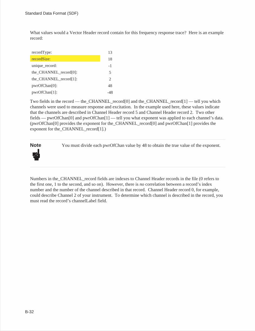
What values would a Vector Header record contain for this frequency response trace? Here is an examplerecord:
recordType: 13
recordSize: 18
unique_record: -1
the_CHANNEL_record[0]: 5
the_CHANNEL_record[1]: 2
pwrOfChan[0]: 48
pwrOfChan[1]: -48
Two fields in the record — the_CHANNEL_record[0] and the_CHANNEL_record[1] — tell you whichchannels were used to measure response and excitation. In the example used here, these values indicatethat the channels are described in Channel Header record 5 and Channel Header record 2. Two otherfields — pwrOfChan[0] and pwrOfChan[1] — tell you what exponent was applied to each channel’s data.(pwrOfChan[0] provides the exponent for the_CHANNEL_record[0] and pwrOfChan[1] provides theexponent for the_CHANNEL_record[1].)
Note You must divide each pwrOfChan value by 48 to obtain the true value of the exponent.
Numbers in the_CHANNEL_record fields are indexes to Channel Header records in the file (0 refers tothe first one, 1 to the second, and so on). However, there isnocorrelation between a record’s indexnumber and the number of the channel described in that record. Channel Header record 0, for example,could describe Channel 2 of your instrument. To determine which channel is described in the record, youmust read the record’s channelLabel field.
Standard Data Format (SDF)
B-32
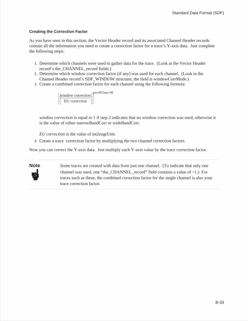
Creating the Correction Factor
As you have seen in this section, the Vector Header record and its associated Channel Header recordscontain all the information you need to create a correction factor for a trace’s Y-axis data. Just completethe following steps:
1. Determine which channels were used to gather data for the trace. (Look at the Vector Headerrecord’s the_CHANNEL_record fields.)
2. Determine which window correction factor (if any) was used for each channel. (Look in theChannel Header record’s SDF_WINDOW structure; the field is windowCorrMode.)
3. Create a combined correction factor for each channel using the following formula:
window correction
EU correction
pwrOfChan⁄ 48
window correctionis equal to 1 if step 2 indicates that no window correction was used, otherwise itis the value of either narrowBandCorr or wideBandCorr.
EU correctionis the value of int2engrUnit.
4. Create a trace correction factor by multiplying the two channel correction factors.
Now you can correct the Y-axis data. Just multiply each Y-axis value by the trace correction factor.
Note Some traces are created with data from just one channel. (To indicate that only one
channel was used, one “the_CHANNEL_record” field contains a value of−1.) Fortraces such as these, the combined correction factor for the single channel is also yourtrace correction factor.
Standard Data Format (SDF)
B-33
Locating a Vector of Y-axis Data
When an SDF file defines just one trace, the Y-axis Data record contains a single vector of Y-axis data.However, when the file defines more than one trace, the record contains many vectors — one for eachtrace. This section tells you how to locate one Y-axis vector in a block of many.
Single-Scan Files
When a file doesnotcontain a Scan Structure record, the structure of the Y-axis data block is quitesimple: the order of vectors in the block is exactly the same as the order of Vector Header records in thefile. The vector described by Vector Header record 0 is first in the block, the one described by VectorHeader record 1 is second, and so on.
Multiple-Scan Files
When a file does contain a Scan Structure record, the structure of the Y-axis data block is somewhat morecomplex:
• The block contains more than one set vectors.• The vectors can be organized in two different ways.
A single scan puts a complete set of vectors in the Y-axis data block — one for each Vector Headerrecord. Each additional scan adds another set of vectors to the block.
The two types of vector organization are referred to as Scan and Depth. The scan_type field in the ScanStructure record tells you which type of organization was used for your file. The following exampleshows how Scan and Depth differ.
The example file contains two Data Header records and seven Vector Header records(num_of_DATA_HDR_record and num_of_Vector_record in the File Header record have values of 2 and7, respectively). Its Y-axis data block includes three scans of data (num_of_scan in the Scan Structurerecord has a value of 3). The first Data Header record is linked to the first three Vector Header records(total_rows total_cols = 3; first_VECTOR_recordNum = 0) and the second is linked to the last four(total_rows total_cols = 4; first_VECTOR_recordNum = 3).
Standard Data Format (SDF)
B-34
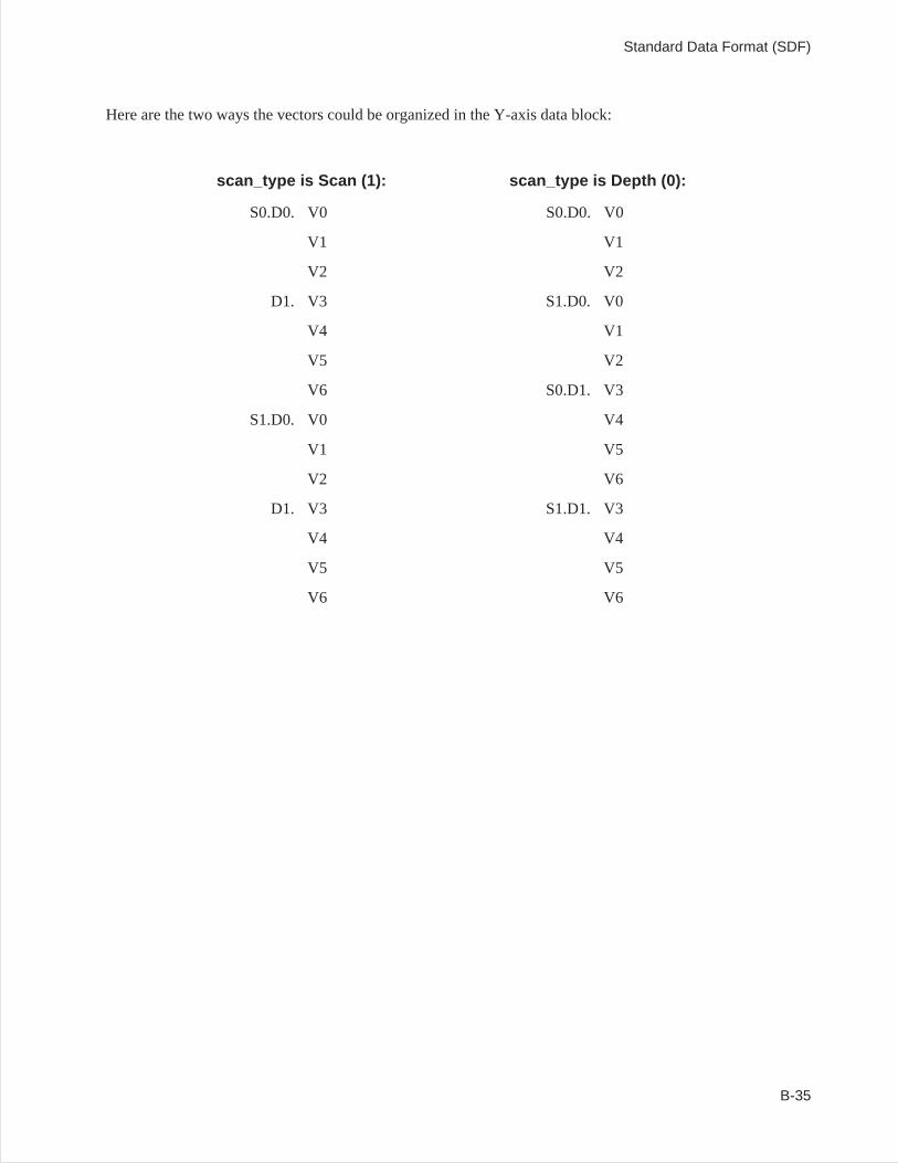
Here are the two ways the vectors could be organized in the Y-axis data block:
scan_type is Scan (1): scan_type is Depth (0):
S0.D0. V0 S0.D0. V0
V1 V1
V2 V2
D1. V3 S1.D0. V0
V4 V1
V5 V2
V6 S0.D1. V3
S1.D0. V0 V4
V1 V5
V2 V6
D1. V3 S1.D1. V3
V4 V4
V5 V5
V6 V6
Standard Data Format (SDF)
B-35
Time Capture Data
A time capture data contains long streams of raw time data captured by an instrument. The files containssome or all of the following results.
Time Data
Time data is identified in a time capture file with the following SDF_DATA_HDR attributes:
dataType 0 (time data)
ydata_type SHORT16 or LONG32
scanData 1
The time data should always be the first result in a time capture file. To convert the data from its integerform to volts, you need to determine the channel header that belongs to the data and get the scaling factorfrom the channel header.
The time capture data is stored with multiple rows of data, one row for each channel of captured data. Fora given row, the desired SDF_VECTOR_HDR number is (first_VECTOR_recordNum+ row). Afterlocating the SDF_VECTOR_HDR for this row, find the channel number from the_CHANNEL_record[0].After locating the SDF_CHANNEL_HDR, you can scale the time capture data to volts by using the scalevalues in the SDF_CHANNEL_HDR. For each time capture value in the data result (defined astime_data[i]):
time_volts[i] =channelOffset+ (channelScale time_data[i])
To determine the total number of time capture points, you need to know now many scans are in the file.The number of usable scans can be determined from thelast_scan_indexfield in theSDF_SCAN_STRUCT. The number of usable points per scan can be determined from thelast_valid_index in the SDF_DATA_HDR. The total number of time capture data points is:
time_capture_points = (last_valid_index+1) (last_scan_index+1)
Overload Data
Overload data is identified in a time capture file with the following SDF_DATA_HDR attributes:
dataType 46 (overload data)
ydata_type SHORT16
num_of_points 1
scanData 1
This data result identifies whether an overload occurred in each scan of a time capture. There is one ofthese results for each channel of a time capture.
Standard Data Format (SDF)
B-36
Frequency Correction Data
Frequency Correction Data is identified in a time capture file with the following SDF_DATA_HDRattributes:
dataType 34 (frequency corrections)
scanData 0
This data result contains the frequency domain corrections for the time capture data. It is the same size asthe instrument’s Spectrum data result. There is one of these results for each channel of a time capture.
Compressed Time Data
The compressed time data result in a time capture file contains a compressed representation of the entiretime capture file of each channel of time data. The time data is sampled and minimum and maximumdata values for each sampled region are stored for each data point. The compressed time data is identifiedin a time capture file with the following SDF_DATA_HDR attributes:
dataType 45 (decimated time data) or47 (compressed time data)
ydata_type SHORT16 or LONG32
yPerPoint 5
yIsComplex 0
scanData 0
The 5 values per point represent the following:
minimum real value
minimum imaginary value
maximum real value
maximum imaginary value
overload flag
Since the minimum/maximum values are in integer form, they can be scaled to volts using the samemechanism as for scaling the time data (see above). If the dataType is 45 (decimated time data), then theminimum values equal the maximum values since the data is decimated, not compressed. There is one ofthese results for each channel of a time capture.
Standard Data Format (SDF)
B-37
Tachometer Data
Tachometer data is identified in a time capture file with the following SDF_DATA_HDR attributes:
dataType 37 (tachometer data)
ydata_type LONG32
yIsComplex 0
scanData 0
Each point in the tachometer data is a 32 tachometer counter value which represents time. To interpretthe tachometer data, you need to know how many tachometer points are in the tachometer data, thetachometer frequency, and the number of tachometer pulses per revolution.
number_of_tach_points = (total_rows total_cols− 1 ) num_of_points+ last_valid_index
tach_pulses_per_rev =abscissa_deltaX
tach_frequency =abscissa_firstX
For each tachometer counter value in the tachometer data result (defined as tach_cnt[i]):
tach_time_sec[i] = tach_cnt[i] / tach_frequency
From each consecutive pair of tachometer points, you can compute and instantaneous RPM:
tach_pulse_delta_sec = tach_time_sec[i]− tach_time_sec[i− 1]
tach_pulses_per_min = 60 tach_pulses_per_sec
tach_rpm = tach_pulses_per_min / tach_pulses_per_rev
There may be a delay between the tachometer zero count value (when the tachometer started counting)and the first sample in the time capture data. From the SDF_VECTOR_HDR associated with thetachometer data result, you can locate the corresponding SDF_CHANNEL_HDR. The delay, in seconds,is in theuserDelayfield.
There is only one tachometer result in a time capture.
Standard Data Format (SDF)
B-38
External Trigger Data
External trigger data is identified in a time capture file with the following SDF_DATA_HDR attributes:
dataType 48 (external trigger data)
ydata_type LONG32
yIsComplex 0
scanData 0
If the trigger mode is set to be the external trigger at the time the capture was acquired and the tachometeris turned on, then this data result may be present.
Each point in the external trigger data is a 32 external trigger counter value which represents time. Thereis one time value associated with each scan of the time capture. The external trigger counter value isconverted to a time value the same way as the tachometer data (see above).
Standard Data Format (SDF)
B-39
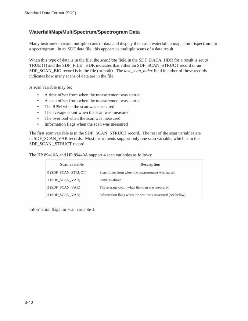
Waterfall/Map/MultiSpectrum/Spectrogram Data
Many instrument create multiple scans of data and display them as a waterfall, a map, a multispectrum, ora spectrogram. In an SDF data file, this appears as multiple scans of a data result.
When this type of data is in the file, thescanDatafield in the SDF_DATA_HDR for a result is set toTRUE (1) and the SDF_FILE _HDR indicates that either an SDF_SCAN_STRUCT record or anSDF_SCAN_BIG record is in the file (or both). Thelast_scan_indexfield in either of these recordsindicates how many scans of data are in the file.
A scan variable may be:
• A time offset from when the measurement was started• A scan offset from when the measurement was started• The RPM when the scan was measured• The average count when the scan was measured• The overload when the scan was measured• Information flags when the scan was measured
The first scan variable is in the SDF_SCAN_STRUCT record. The rest of the scan variables arein SDF_SCAN_VAR records. Most instruments support only one scan variable, which is in theSDF_SCAN _STRUCT record.
The HP 89410A and HP 89440A support 4 scan variables as follows:
Scan variable Description
0 (SDF_SCAN_STRUCT) Scan offset from when the measurement was started
1 (SDF_SCAN_VAR) Same as above
2 (SDF_SCAN_VAR) The average count when the scan was measured
3 (SDF_SCAN_VAR) Information flags when the scan was measured (see below)
Information flags for scan variable 3:
Standard Data Format (SDF)
B-40
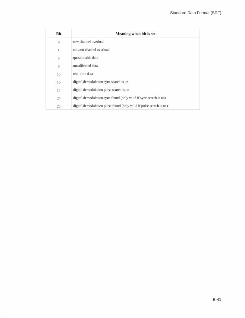
Bit Meaning when bit is set
0 row channel overload
1 column channel overload
8 questionable data
9 uncalibrated data
15 real-time data
16 digital demodulation sync search is on
17 digital demodulation pulse search is on
24 digital demodulation sync found (only valid if sync search is on)
25 digital demodulation pulse found (only valid if pulse search is on)
Standard Data Format (SDF)
B-41
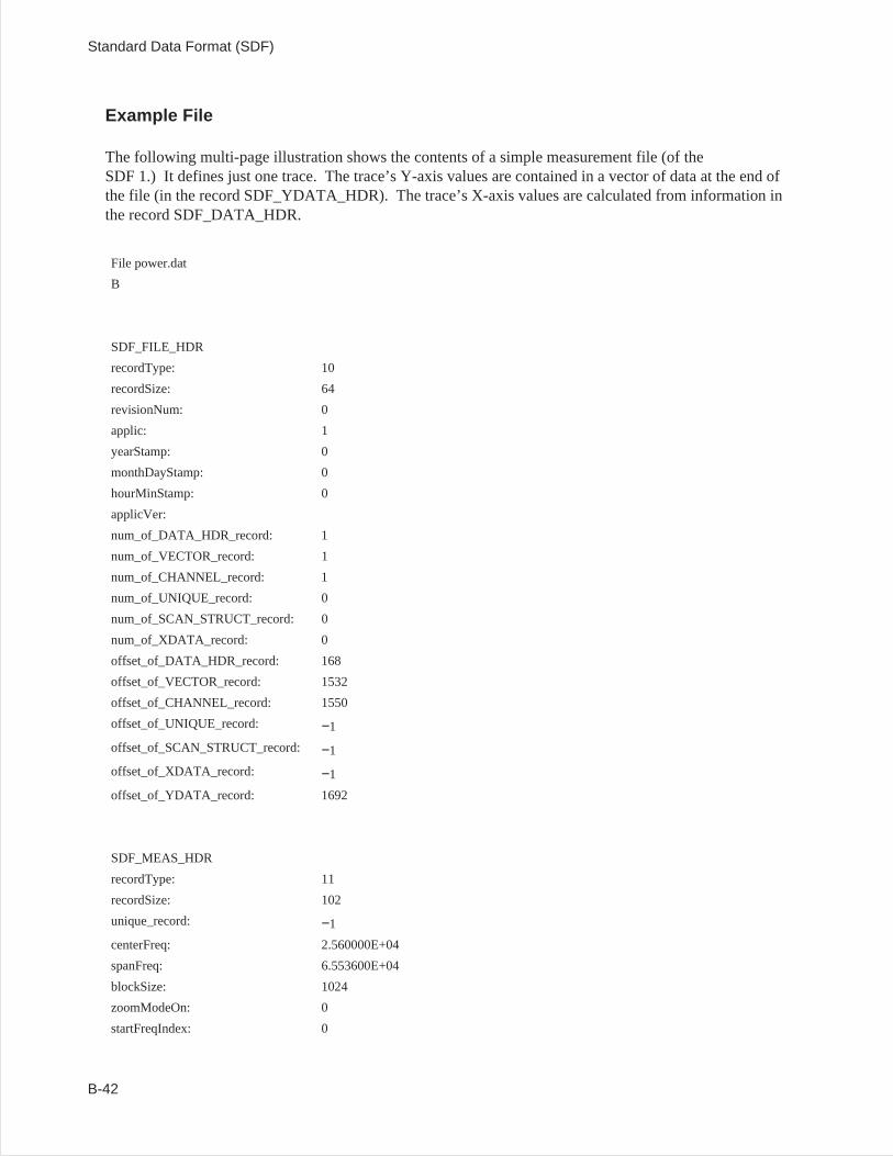
Example File
The following multi-page illustration shows the contents of a simple measurement file (of theSDF 1.) It defines just one trace. The trace’s Y-axis values are contained in a vector of data at the end ofthe file (in the record SDF_YDATA_HDR). The trace’s X-axis values are calculated from information inthe record SDF_DATA_HDR.
File power.dat
B
SDF_FILE_HDR
recordType: 10
recordSize: 64
revisionNum: 0
applic: 1
yearStamp: 0
monthDayStamp: 0
hourMinStamp: 0
applicVer:
num_of_DATA_HDR_record: 1
num_of_VECTOR_record: 1
num_of_CHANNEL_record: 1
num_of_UNIQUE_record: 0
num_of_SCAN_STRUCT_record: 0
num_of_XDATA_record: 0
offset_of_DATA_HDR_record: 168
offset_of_VECTOR_record: 1532
offset_of_CHANNEL_record: 1550
offset_of_UNIQUE_record: −1
offset_of_SCAN_STRUCT_record: −1
offset_of_XDATA_record: −1
offset_of_YDATA_record: 1692
SDF_MEAS_HDR
recordType: 11
recordSize: 102
unique_record: −1
centerFreq: 2.560000E+04
spanFreq: 6.553600E+04
blockSize: 1024
zoomModeOn: 0
startFreqIndex: 0
Standard Data Format (SDF)
B-42
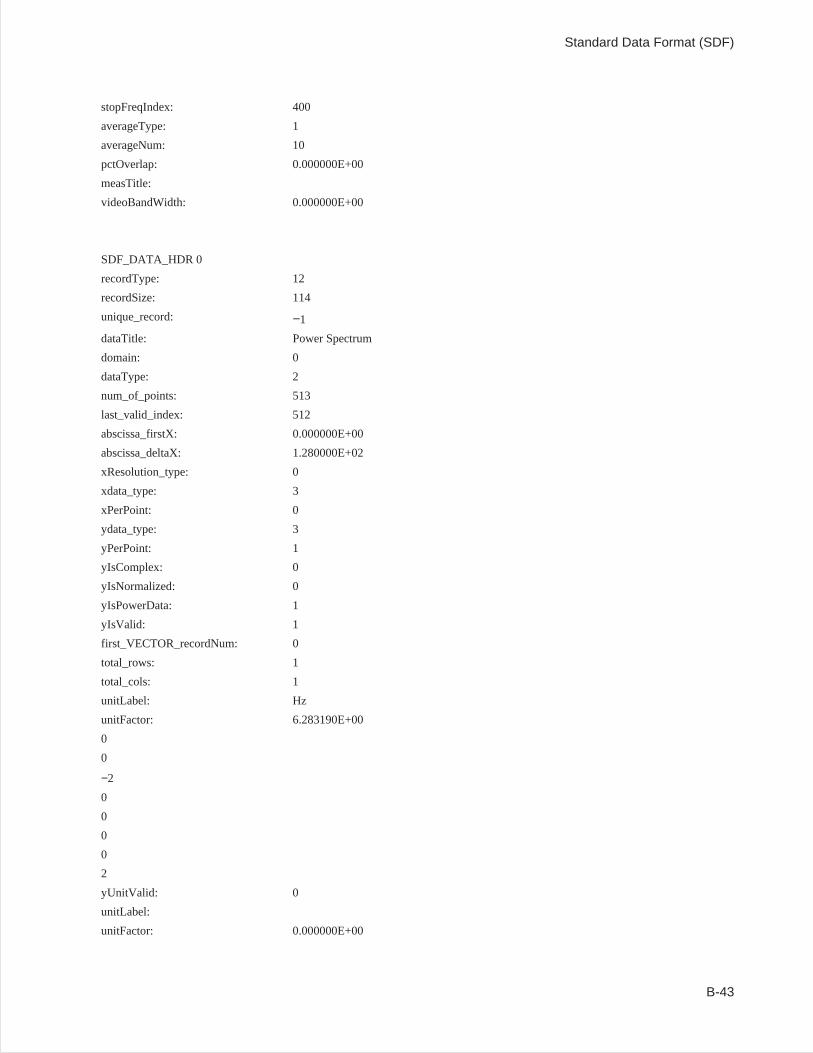
stopFreqIndex: 400
averageType: 1
averageNum: 10
pctOverlap: 0.000000E+00
measTitle:
videoBandWidth: 0.000000E+00
SDF_DATA_HDR 0
recordType: 12
recordSize: 114
unique_record: −1
dataTitle: Power Spectrum
domain: 0
dataType: 2
num_of_points: 513
last_valid_index: 512
abscissa_firstX: 0.000000E+00
abscissa_deltaX: 1.280000E+02
xResolution_type: 0
xdata_type: 3
xPerPoint: 0
ydata_type: 3
yPerPoint: 1
yIsComplex: 0
yIsNormalized: 0
yIsPowerData: 1
yIsValid: 1
first_VECTOR_recordNum: 0
total_rows: 1
total_cols: 1
unitLabel: Hz
unitFactor: 6.283190E+00
0
0
−2
0
0
0
0
2
yUnitValid: 0
unitLabel:
unitFactor: 0.000000E+00
Standard Data Format (SDF)
B-43
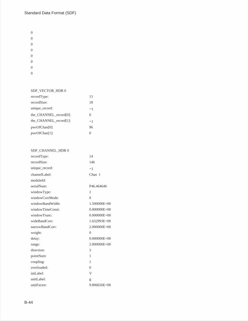
0
0
0
0
0
0
0
0
SDF_VECTOR_HDR 0
recordType: 13
recordSize: 18
unique_record: −1
the_CHANNEL_record[0]: 0
the_CHANNEL_record[1]: −1
pwrOfChan[0]: 96
pwrOfChan[1]: 0
SDF_CHANNEL_HDR 0
recordType: 14
recordSize: 146
unique_record: −1
channelLabel: Chan 1
moduleId:
serialNum: P46.464646
windowType: 1
windowCorrMode: 0
windowBandWidth: 1.500000E+00
windowTimeConst: 0.000000E+00
windowTrunc: 0.000000E+00
wideBandCorr: 1.632993E+00
narrowBandCorr: 2.000000E+00
weight: 0
delay: 0.000000E+00
range: 2.000000E+00
direction: 3
pointNum: 1
coupling: 1
overloaded: 0
intLabel: V
unitLabel: g
unitFactor: 9.806650E+00
Standard Data Format (SDF)
B-44
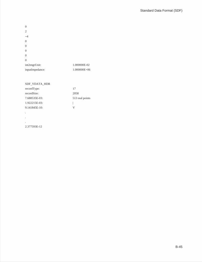
0
2
−4
0
0
0
0
0
int2engrUnit: 1.000000E-02
inputImpedance: 1.000000E+06
SDF_YDATA_HDR
recordType: 17
recordSize: 2058
7.688535E-03: 513 real points
1.922215E-03: |
9.141845E-10: V
.
.
.
2.377593E-12
Standard Data Format (SDF)
B-45

C
Batch Files
Introduction
This chapter documents the batch files included with the Standard Data Format Utilities. These files‘’automate’’ some procedures by performing the two or three steps required. For example,‘’63_SDF.BAT’’ performs both the LIF-to-DOS conversion and the HP 3563A-to-SDF conversion for allHP 3563A/62A files on the specified drive.
You can use the batch files as they are, or copy and modify them to fit your particular needs.
The batch files included are:
63_ML.BAT 60_ML.BAT 69_ML.BAT IB63_ML.BAT
63_MX.BAT 60_MX.BAT 69_MX.BAT IB63_MX.BAT
63_PLOT.BAT 60_PLOT.BAT 69_PLOT.BAT IB63_PLT.BAT
63_SDF.BAT 60_SDF.BAT 69_SDF.BAT IB63_SDF.BAT
C-1
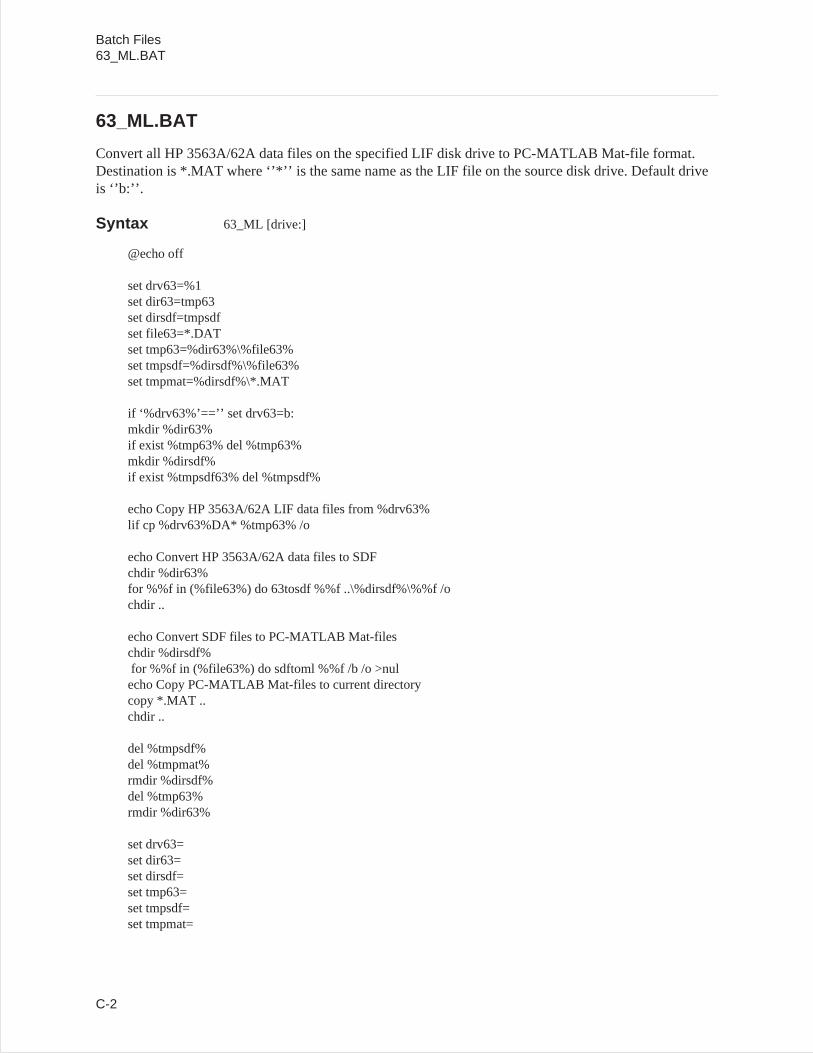
63_ML.BAT
Convert all HP 3563A/62A data files on the specified LIF disk drive to PC-MATLAB Mat-file format.Destination is *.MAT where ‘’*’’ is the same name as the LIF file on the source disk drive. Default driveis ‘’b:’’.
Syntax 63_ML [drive:]
@echo off
set drv63=%1set dir63=tmp63set dirsdf=tmpsdfset file63=*.DATset tmp63=%dir63%\%file63%set tmpsdf=%dirsdf%\%file63%set tmpmat=%dirsdf%\*.MAT
if ‘%drv63%’==’’ set drv63=b:mkdir %dir63%if exist %tmp63% del %tmp63%mkdir %dirsdf%if exist %tmpsdf63% del %tmpsdf%
echo Copy HP 3563A/62A LIF data files from %drv63%lif cp %drv63%DA* %tmp63% /o
echo Convert HP 3563A/62A data files to SDFchdir %dir63%for %%f in (%file63%) do 63tosdf %%f ..\%dirsdf%\%%f /ochdir ..
echo Convert SDF files to PC-MATLAB Mat-fileschdir %dirsdf%for %%f in (%file63%) do sdftoml %%f /b /o >nulecho Copy PC-MATLAB Mat-files to current directorycopy *.MAT ..chdir ..
del %tmpsdf%del %tmpmat%rmdir %dirsdf%del %tmp63%rmdir %dir63%
set drv63=set dir63=set dirsdf=set tmp63=set tmpsdf=set tmpmat=
Batch Files63_ML.BAT
C-2
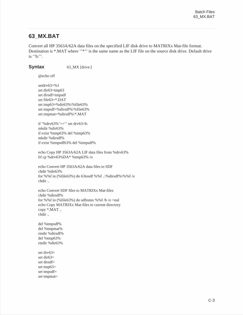
63_MX.BAT
Convert all HP 3563A/62A data files on the specified LIF disk drive to MATRIXx Mat-file format.Destination is *.MAT where ‘’*’’ is the same name as the LIF file on the source disk drive. Default driveis ‘’b:’’.
Syntax 63_MX [drive:]
@echo off
setdrv63=%1set dir63=tmp63set dirsdf=tmpsdfset file63=*.DATset tmp63=%dir63%\%file63%set tmpsdf=%dirsdf%\%file63%set tmpmat=%dirsdf%\*.MAT
if ‘%drv63%’==’’ set drv63=b:mkdir %dir63%if exist %tmp63% del %tmp63%mkdir %dirsdf%if exist %tmpsdf63% del %tmpsdf%
echo Copy HP 3563A/62A LIF data files from %drv63%lif cp %drv63%DA* %tmp63% /o
echo Convert HP 3563A/62A data files to SDFchdir %dir63%for %%f in (%file63%) do 63tosdf %%f ..\%dirsdf%\%%f /ochdir ..
echo Convert SDF files to MATRIXx Mat-fileschdir %dirsdf%for %%f in (%file63%) do sdftomx %%f /b /o >nulecho Copy MATRIXx Mat-files to current directorycopy *.MAT ..chdir ..
del %tmpsdf%del %tmpmat%rmdir %dirsdf%del %tmp63%rmdir %dir63%
set drv63=set dir63=set dirsdf=set tmp63=set tmpsdf=set tmpmat=
Batch Files63_MX.BAT
C-3
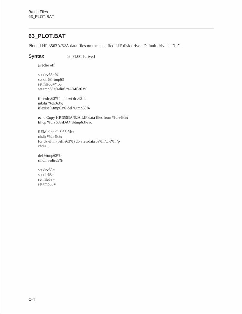
63_PLOT.BAT
Plot all HP 3563A/62A data files on the specified LIF disk drive. Default drive is ‘’b:’’.
Syntax 63_PLOT [drive:]
@echo off
set drv63=%1set dir63=tmp63set file63=*.63set tmp63=%dir63%\%file63%
if ‘%drv63%’==’’ set drv63=b:mkdir %dir63%if exist %tmp63% del %tmp63%
echo Copy HP 3563A/62A LIF data files from %drv63%lif cp %drv63%DA* %tmp63% /o
REM plot all *.63 fileschdir %dir63%for %%f in (%file63%) do viewdata %%f /t:%%f /pchdir ..
del %tmp63%rmdir %dir63%
set drv63=set dir63=set file63=set tmp63=
Batch Files63_PLOT.BAT
C-4
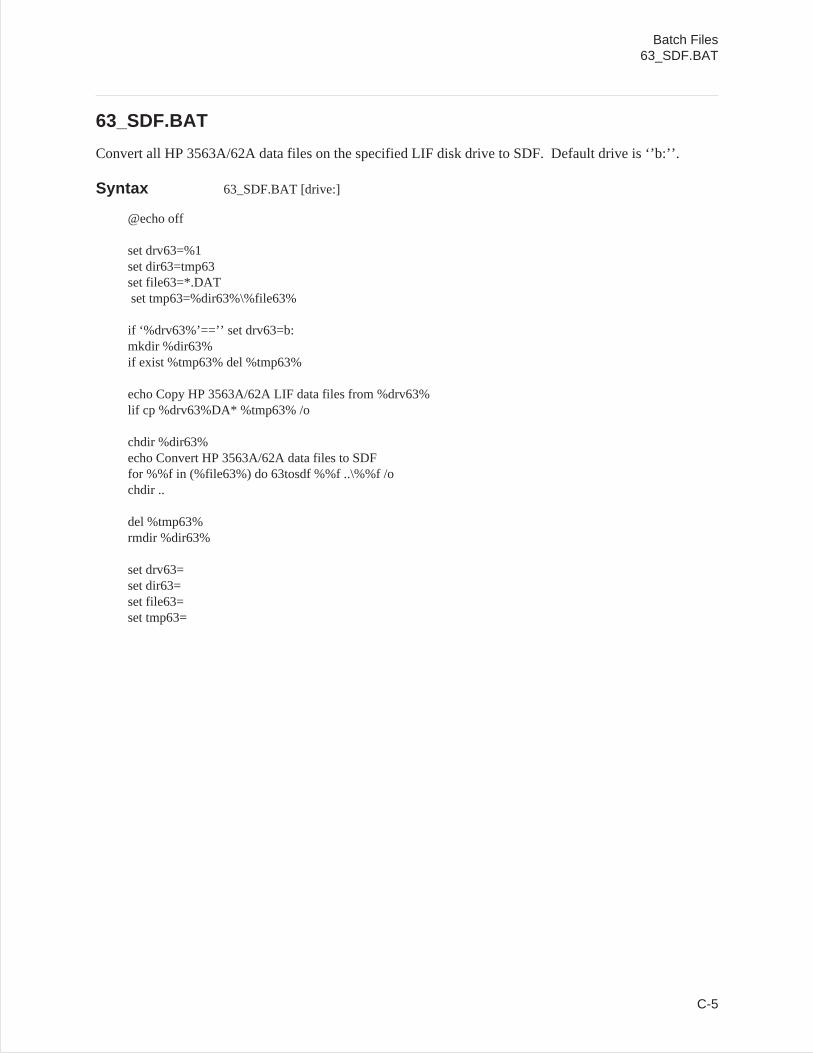
63_SDF.BAT
Convert all HP 3563A/62A data files on the specified LIF disk drive to SDF. Default drive is ‘’b:’’.
Syntax 63_SDF.BAT [drive:]
@echo off
set drv63=%1set dir63=tmp63set file63=*.DATset tmp63=%dir63%\%file63%
if ‘%drv63%’==’’ set drv63=b:mkdir %dir63%if exist %tmp63% del %tmp63%
echo Copy HP 3563A/62A LIF data files from %drv63%lif cp %drv63%DA* %tmp63% /o
chdir %dir63%echo Convert HP 3563A/62A data files to SDFfor %%f in (%file63%) do 63tosdf %%f ..\%%f /ochdir ..
del %tmp63%rmdir %dir63%
set drv63=set dir63=set file63=set tmp63=
Batch Files63_SDF.BAT
C-5

60_ML.BAT
Convert all HP 3560A data files that are transferred over the RS-232 port to PC-MATLAB Mat-fileformat. The default port is ‘’1’’ (COM1). The default baud rate is ‘’9600’’.
Syntax 60_ML.BAT [port] [baud]
@echo off
set port60=%1set baud60=%2set temp60=temp60set dire60=tempsdf
if ‘%port60%’==’’ set port60=1if ‘%baud60%’==’’ set baud60=9600
mkdir %dire60%chdir %dire60%echo y | del %dire60%
download /o %temp60%.x32 /p%port60% /b%baud%
x32tobin /o %temp60%.x32 %temp60%.bindel %temp60%.x32
60tosdf /o %temp60%.bindel %temp60%.bin
for %%f in (*.dat) do sdftoml %%f /b /o >nulcopy *.mat ..chdir ..
echo y | del %dire60%rmdir %dire60%
set port60=set baud60=set temp60=set dire60=
Batch Files60_ML.BAT
C-6

60_MX.BAT
Convert all HP 3560A data files that are transferred over the RS-232 port to MATRIXx Mat-file format.The default port is ‘’1’’ (COM1). The default baud rate is ‘’9600’’.
Syntax 60_MX.BAT [port] [baud]
@echo off
set port60=%1set baud60=%2set temp60=temp60set dire60=tempsdf
if ‘%port60%’==’’ set port60=1if ‘%baud60%’==’’ set baud60=9600
mkdir %dire60%chdir %dire60%echo y | del %dire60%
download /o %temp60%.x32 /p%port60% /b%baud%
x32tobin /o %temp60%.x32 %temp60%.bindel %temp60%.x32
60tosdf /o %temp60%.bindel %temp60%.bin
for %%f in (*.dat) do sdftomx %%f /b /o >nulcopy *.mat ..chdir ..
echo y | del %dire60%rmdir %dire60%
set port60=set baud60=set temp60=set dire60=
Batch Files60_MX.BAT
C-7
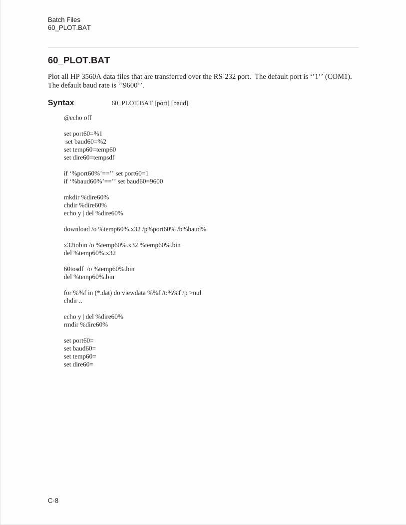
60_PLOT.BAT
Plot all HP 3560A data files that are transferred over the RS-232 port. The default port is ‘’1’’ (COM1).The default baud rate is ‘’9600’’.
Syntax 60_PLOT.BAT [port] [baud]
@echo off
set port60=%1set baud60=%2set temp60=temp60set dire60=tempsdf
if ‘%port60%’==’’ set port60=1if ‘%baud60%’==’’ set baud60=9600
mkdir %dire60%chdir %dire60%echo y | del %dire60%
download /o %temp60%.x32 /p%port60% /b%baud%
x32tobin /o %temp60%.x32 %temp60%.bindel %temp60%.x32
60tosdf /o %temp60%.bindel %temp60%.bin
for %%f in (*.dat) do viewdata %%f /t:%%f /p >nulchdir ..
echo y | del %dire60%rmdir %dire60%
set port60=set baud60=set temp60=set dire60=
Batch Files60_PLOT.BAT
C-8
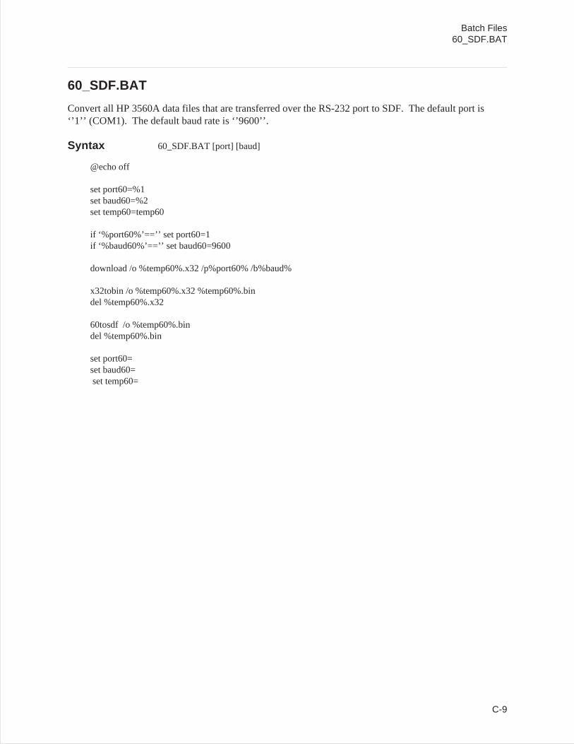
60_SDF.BAT
Convert all HP 3560A data files that are transferred over the RS-232 port to SDF. The default port is‘’1’’ (COM1). The default baud rate is ‘’9600’’.
Syntax 60_SDF.BAT [port] [baud]
@echo off
set port60=%1set baud60=%2set temp60=temp60
if ‘%port60%’==’’ set port60=1if ‘%baud60%’==’’ set baud60=9600
download /o %temp60%.x32 /p%port60% /b%baud%
x32tobin /o %temp60%.x32 %temp60%.bindel %temp60%.x32
60tosdf /o %temp60%.bindel %temp60%.bin
set port60=set baud60=set temp60=
Batch Files60_SDF.BAT
C-9
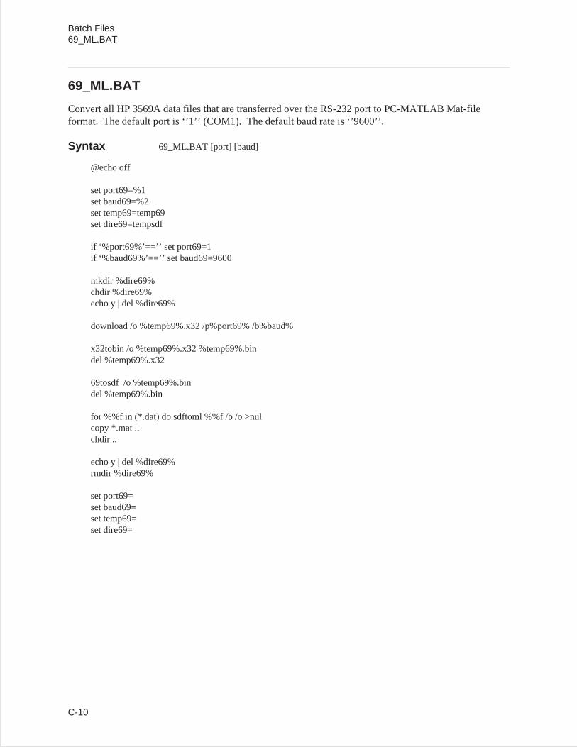
69_ML.BAT
Convert all HP 3569A data files that are transferred over the RS-232 port to PC-MATLAB Mat-fileformat. The default port is ‘’1’’ (COM1). The default baud rate is ‘’9600’’.
Syntax 69_ML.BAT [port] [baud]
@echo off
set port69=%1set baud69=%2set temp69=temp69set dire69=tempsdf
if ‘%port69%’==’’ set port69=1if ‘%baud69%’==’’ set baud69=9600
mkdir %dire69%chdir %dire69%echo y | del %dire69%
download /o %temp69%.x32 /p%port69% /b%baud%
x32tobin /o %temp69%.x32 %temp69%.bindel %temp69%.x32
69tosdf /o %temp69%.bindel %temp69%.bin
for %%f in (*.dat) do sdftoml %%f /b /o >nulcopy *.mat ..chdir ..
echo y | del %dire69%rmdir %dire69%
set port69=set baud69=set temp69=set dire69=
Batch Files69_ML.BAT
C-10
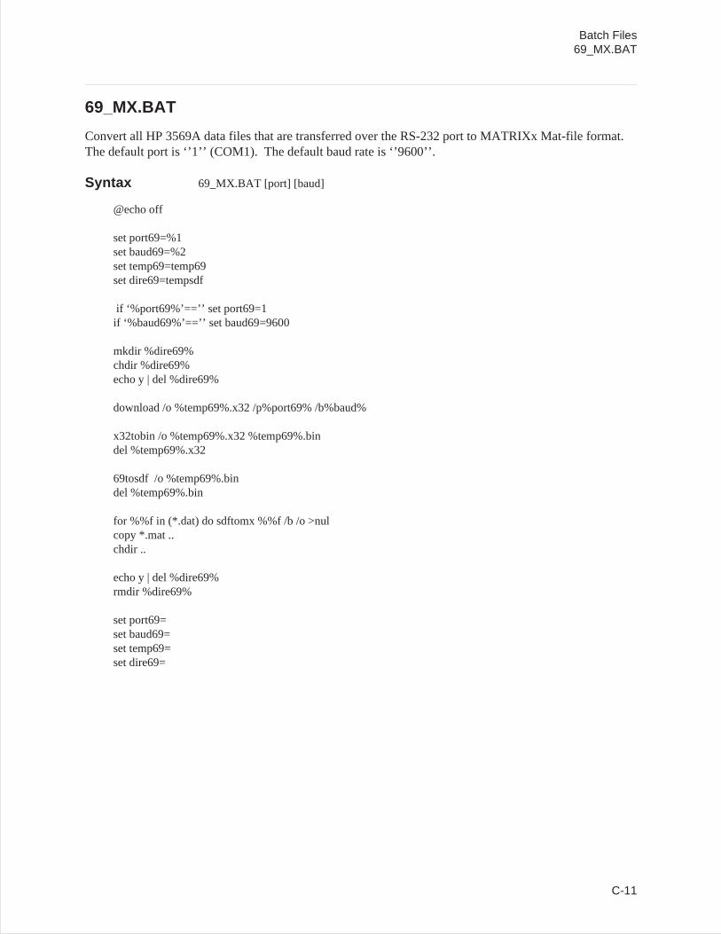
69_MX.BAT
Convert all HP 3569A data files that are transferred over the RS-232 port to MATRIXx Mat-file format.The default port is ‘’1’’ (COM1). The default baud rate is ‘’9600’’.
Syntax 69_MX.BAT [port] [baud]
@echo off
set port69=%1set baud69=%2set temp69=temp69set dire69=tempsdf
if ‘%port69%’==’’ set port69=1if ‘%baud69%’==’’ set baud69=9600
mkdir %dire69%chdir %dire69%echo y | del %dire69%
download /o %temp69%.x32 /p%port69% /b%baud%
x32tobin /o %temp69%.x32 %temp69%.bindel %temp69%.x32
69tosdf /o %temp69%.bindel %temp69%.bin
for %%f in (*.dat) do sdftomx %%f /b /o >nulcopy *.mat ..chdir ..
echo y | del %dire69%rmdir %dire69%
set port69=set baud69=set temp69=set dire69=
Batch Files69_MX.BAT
C-11
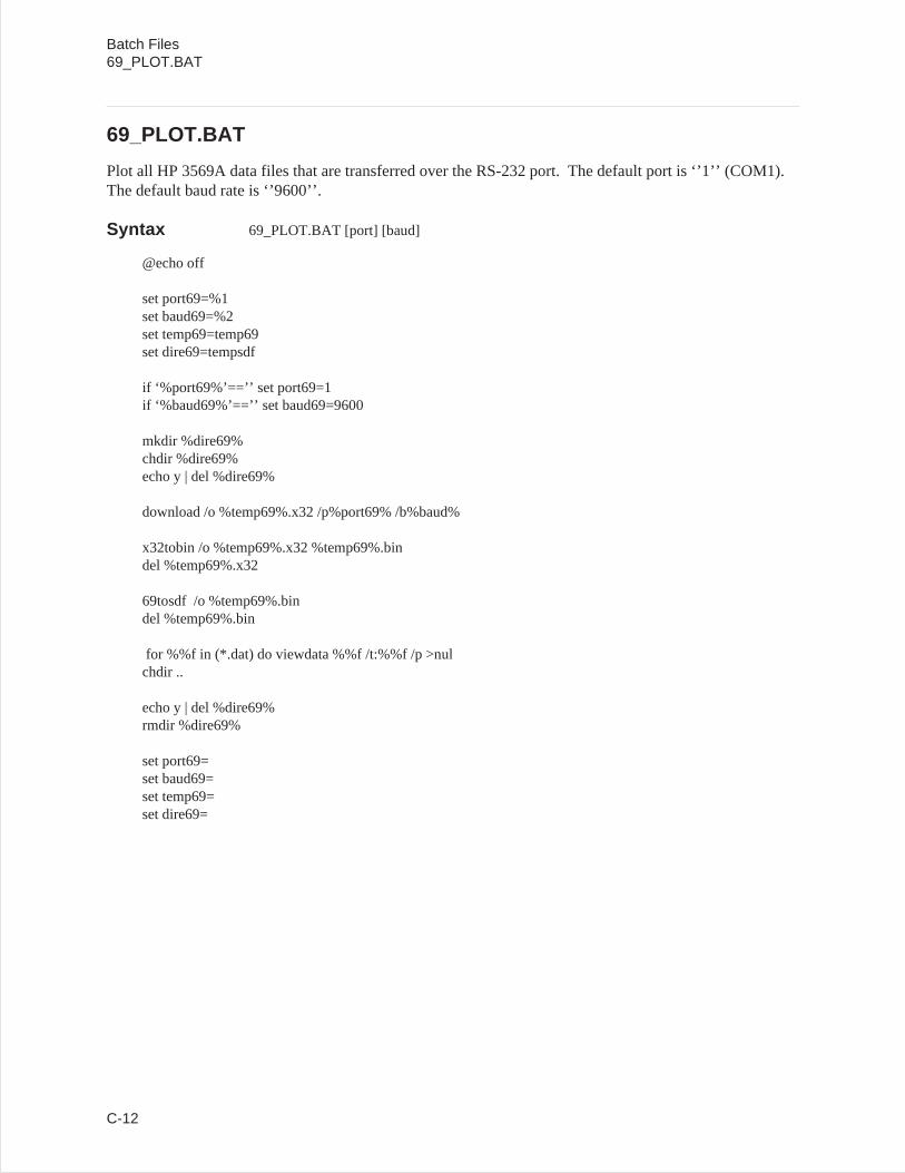
69_PLOT.BAT
Plot all HP 3569A data files that are transferred over the RS-232 port. The default port is ‘’1’’ (COM1).The default baud rate is ‘’9600’’.
Syntax 69_PLOT.BAT [port] [baud]
@echo off
set port69=%1set baud69=%2set temp69=temp69set dire69=tempsdf
if ‘%port69%’==’’ set port69=1if ‘%baud69%’==’’ set baud69=9600
mkdir %dire69%chdir %dire69%echo y | del %dire69%
download /o %temp69%.x32 /p%port69% /b%baud%
x32tobin /o %temp69%.x32 %temp69%.bindel %temp69%.x32
69tosdf /o %temp69%.bindel %temp69%.bin
for %%f in (*.dat) do viewdata %%f /t:%%f /p >nulchdir ..
echo y | del %dire69%rmdir %dire69%
set port69=set baud69=set temp69=set dire69=
Batch Files69_PLOT.BAT
C-12

69_SDF.BAT
Convert all HP 3569A data files that are transferred over the RS-232 port to SDF. The default port is‘’1’’ (COM1). The default baud rate is ‘’9600’’.
Syntax 69_SDF.BAT [port] [baud]
@echo off
set port69=%1set baud69=%2set temp69=temp69
if ‘%port69%’==’’ set port69=1if ‘%baud69%’==’’ set baud69=9600
download /o %temp69%.x32 /p%port69% /b%baud%
x32tobin /o %temp69%.x32 %temp69%.bindel %temp69%.x32
69tosdf /o %temp69%.bindel %temp69%.bin
set port69=set baud69=set temp69=
Batch Files69_SDF.BAT
C-13
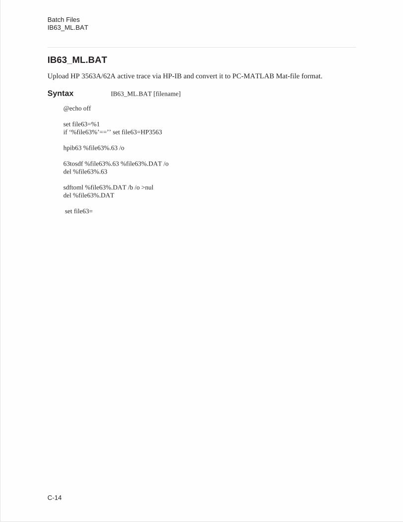
IB63_ML.BAT
Upload HP 3563A/62A active trace via HP-IB and convert it to PC-MATLAB Mat-file format.
Syntax IB63_ML.BAT [filename]
@echo off
set file63=%1if ‘%file63%’==’’ set file63=HP3563
hpib63 %file63%.63 /o
63tosdf %file63%.63 %file63%.DAT /odel %file63%.63
sdftoml %file63%.DAT /b /o >nuldel %file63%.DAT
set file63=
Batch FilesIB63_ML.BAT
C-14
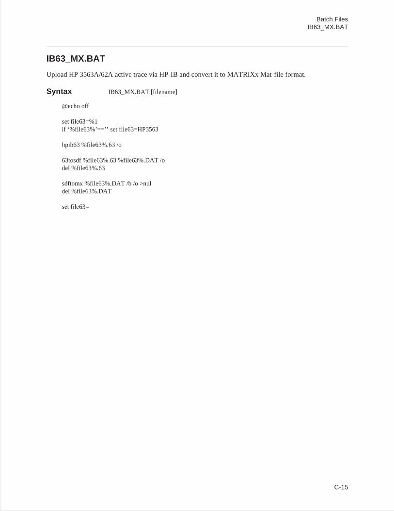
IB63_MX.BAT
Upload HP 3563A/62A active trace via HP-IB and convert it to MATRIXx Mat-file format.
Syntax IB63_MX.BAT [filename]
@echo off
set file63=%1if ‘%file63%’==’’ set file63=HP3563
hpib63 %file63%.63 /o
63tosdf %file63%.63 %file63%.DAT /odel %file63%.63
sdftomx %file63%.DAT /b /o >nuldel %file63%.DAT
set file63=
Batch FilesIB63_MX.BAT
C-15
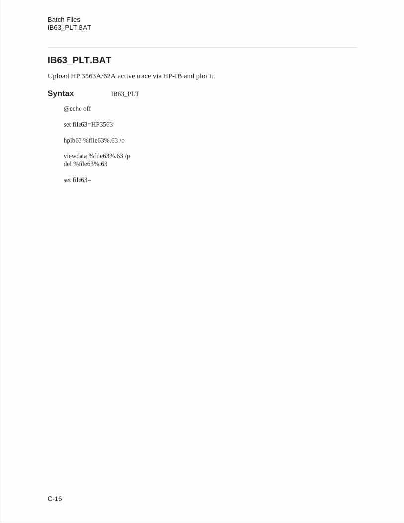
IB63_PLT.BAT
Upload HP 3563A/62A active trace via HP-IB and plot it.
Syntax IB63_PLT
@echo off
set file63=HP3563
hpib63 %file63%.63 /o
viewdata %file63%.63 /pdel %file63%.63
set file63=
Batch FilesIB63_PLT.BAT
C-16
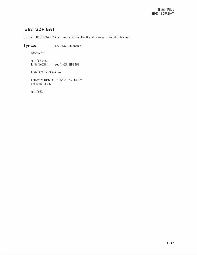
IB63_SDF.BAT
Upload HP 3563A/62A active trace via HI-IB and convert it to SDF format.
Syntax IB63_SDF [filename]
@echo off
set file63=%1if ‘%file63%’==’’ set file63=HP3563
hpib63 %file63%.63 /o
63tosdf %file63%.63 %file63%.DAT /odel %file63%.63
set file63=
Batch FilesIB63_SDF.BAT
C-17

INDEX
!60TOSDF 4-563TOSDF 4-7660TOSDF 4-869TOSDF 4-988TOSDF 4-1189TOSDF 4-13
AASCII file
converting to SDF 4-15ASCTOSDF 4-15
Bbackup
LIF disks 3-20batch files C-1
Cconverting DOS to LIF 3-10converting LIF to DOS 3-10converting SDF to HP 3563A/62A4-36copying LIF files 3-10copying multiple files 3-12Correcting Y-axis data B-30cosine filter
raised 8-2root-raised 8-2
create waveform 8-1
Ddata results (SDF) 2-2deleting LIF files 3-15DFDATA63 4-18DFHDR63 4-20diagnostics
LIF 3-20disk cache programs3-2disk drives
supported 3-2DOS to LIF conversion 3-10DOWNLOAD 4-22
EExample file B-42
Ffilter
gaussian 8-2raised cosine 8-2root-raised cosine 8-2
filtrsdf.mex 7-2formatting LIF directory 3-17
Ggauss.mcd (Mathcad)8-2gaussian filter 8-2Gaussian MSK waveform8-1gmsk.mcd (Mathcad) 8-1
HHEADER63 4-23HP 3560A files
converting to SDF 4-5HP 3562A file types 3-9HP 3562A files
converting to SDF 4-7HP 3563A capture file
converting data 4-18converting header 4-20
HP 3563A data headerconverting to ASCII 4-23
HP 3563A file types 3-9HP 3563A files
converting to SDF 4-7HP 3563A setup state
converting to ASCII 4-55HP 3563A synthesis file
converting 4-62HP 3563A throughput file
converting data 4-18converting header 4-20
HP 35660A filesconverting to SDF 4-8
HP 3569A filesconverting to SDF 4-9
HP 3588A filesconverting to SDF 4-11
HP 3588A setup stateconverting to ASCII 4-57
HP 3589A filesconverting to SDF 4-13
HP 3589A setup state
i
converting to ASCII 4-59HP894x0A
with Mathcad 8-1
Iinitializing LIF directory 3-17installing SDF libraries 1-10installing SDF Utilities 1-10
LLIF CHECK 3-7LIF CHK 3-7LIF COPY 3-10LIF CP 3-10LIF DEL 3-15LIF DIR 3-8LIF files
deleting 3-15LIF INIT 3-17LIF LS 3-8LIF RM 3-15LIF SCAN 3-5LIF to DOS conversion 3-10LIFDIAG 3-20Locating a Vector B-34
Mmap 2-4Map Data B-40matdemo.tim 7-3Mathcad 8-1MATLAB MEX-Files 7-1measurement data2-2measurement results (SDF)2-2multiple files
copying 3-12MultiSpectrum Data B-40
Nnumber of input channels2-3
Oofstsine.mcd (Mathcad)8-1online help 3-3, 4-4
Pprinting SDF files 4-30
QQPSK waveform 8-2qpsk.mcd (Mathcad) 8-2
Rraiscos.mcd (Mathcad)8-2raised cosine filter 8-2Reconstructing a traceB-27Record
basic SDF unit B-2descriptions B-6order B-3special fields B-5
root-raised cosine filter 8-2rootcos.mcd (Mathcad)8-2rows (SDF file) 2-3
Sscans (SDF file) 2-4scans, time capture (SDF file)2-5SDF
library functions 6-1storing data 6-2
SDF fileconverting to ASCII 4-39
SDF filesconverting to Data Set 584-35converting to MATRIXx 4-46converting to PC-MATLAB 4-44
SDF libraries 6-2SdfChanHdr 6-9SdfClose 6-4SdfCommentHdr 6-20SdfCommentRead6-21SdfCommentWrite 6-22SdfDataHdr 6-7SdfFileHdr 6-5SdfMeasHdr 6-6SdfOpen 6-3SDFPRINT 4-30SdfScanBig 6-11SdfScanData 6-18SdfScanStruct 6-10SdfScansUsed6-13SdfScanVar 6-12SDFTEXT 4-34SDFTO58 4-35SDFTO63 4-36SDFTOASC 4-39SDFTOBIN 4-42SDFTOML 4-44SDFTOMX 4-46SDFTOSDF 4-50SdfTrunc 6-19SdfVectHdr 6-8SdfXdata 6-17SDFYDATA 4-54, 6-14
Index (Continued)
ii
SdfYdataWrite 6-16SETUP63 4-55SETUP88 4-57SETUP89 4-59signals (Mathcad) 8-1Spectrogram DataB-40Standard Data Format6-2, B-1Structure
descriptions B-6SYNTH63 4-62
Ttcdemo.m 7-4tcdemo2.m 7-5time capture 2-5Time Capture Data B-36Trace
reconstructing B-27
VVector
locating B-34Viewdata 5-1
Wwaterfall 2-4Waterfall Data B-40waveform, create 8-1wild cards
copying files 3-12
XX32TOBIN 4-64
YY-axis Data
correcting B-30vector B-34
Index (Continued)
iii