Embed Size (px)
Citation preview
Data Communications
Circuit Switching
Switching NetworksLong distance transmission is typically done
over a network of switched nodesNodes not concerned with content of dataEnd devices are stations
Computer, terminal, phone, etc.
A collection of nodes and connections is a communications network
Data routed by being switched from node to node
NodesNodes may connect to other nodes only, or
to stations and other nodesNode to node links usually multiplexedNetwork is usually partially connected
Some redundant connections are desirable for reliability
Two different switching technologiesCircuit switchingPacket switching
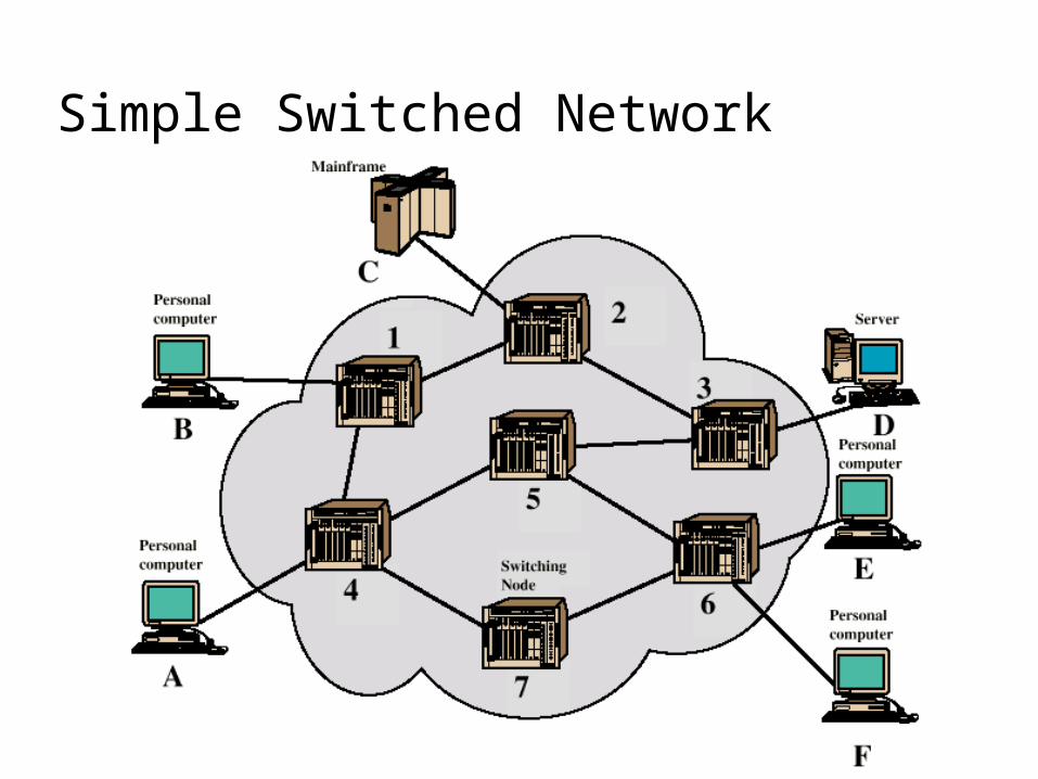
Simple Switched Network
Circuit SwitchingDedicated communication path between
two stationsThree phases
EstablishTransferDisconnect
Must have switching capacity and channel capacity to establish connection
Must have intelligence to work out routing
Circuit Switching - ApplicationsInefficient
Channel capacity dedicated for duration of connection
If no data, capacity wasted
Set up (connection) takes timeOnce connected, transfer is transparentDeveloped for voice traffic (phone)
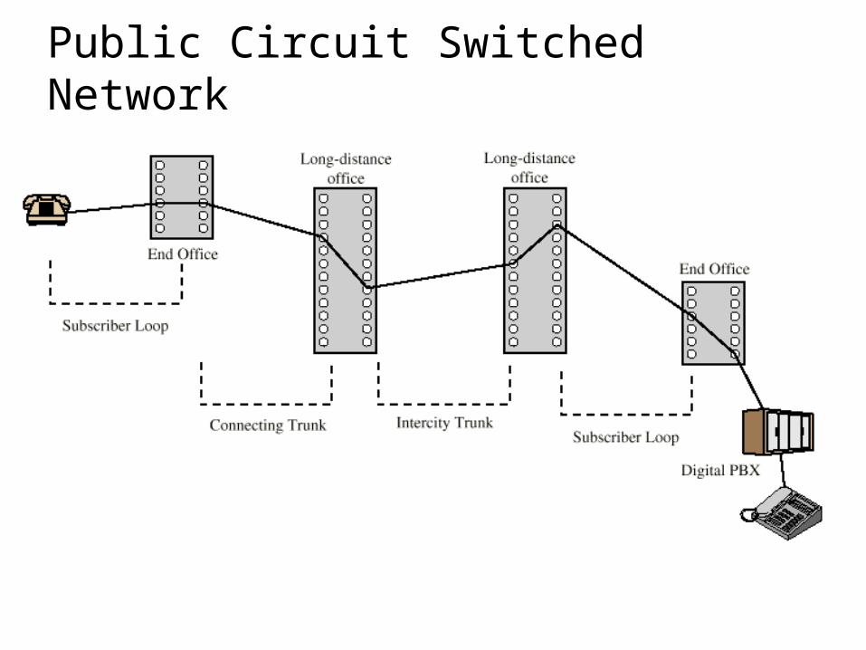
Public Circuit Switched Network
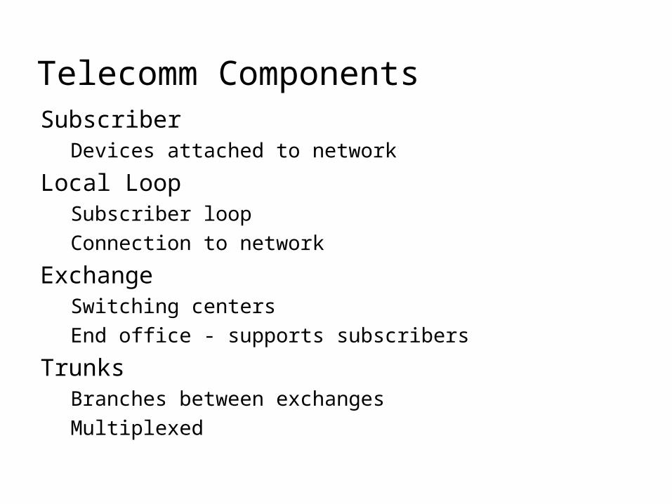
Telecomm ComponentsSubscriber
Devices attached to network
Local LoopSubscriber loopConnection to network
ExchangeSwitching centersEnd office - supports subscribers
TrunksBranches between exchangesMultiplexed
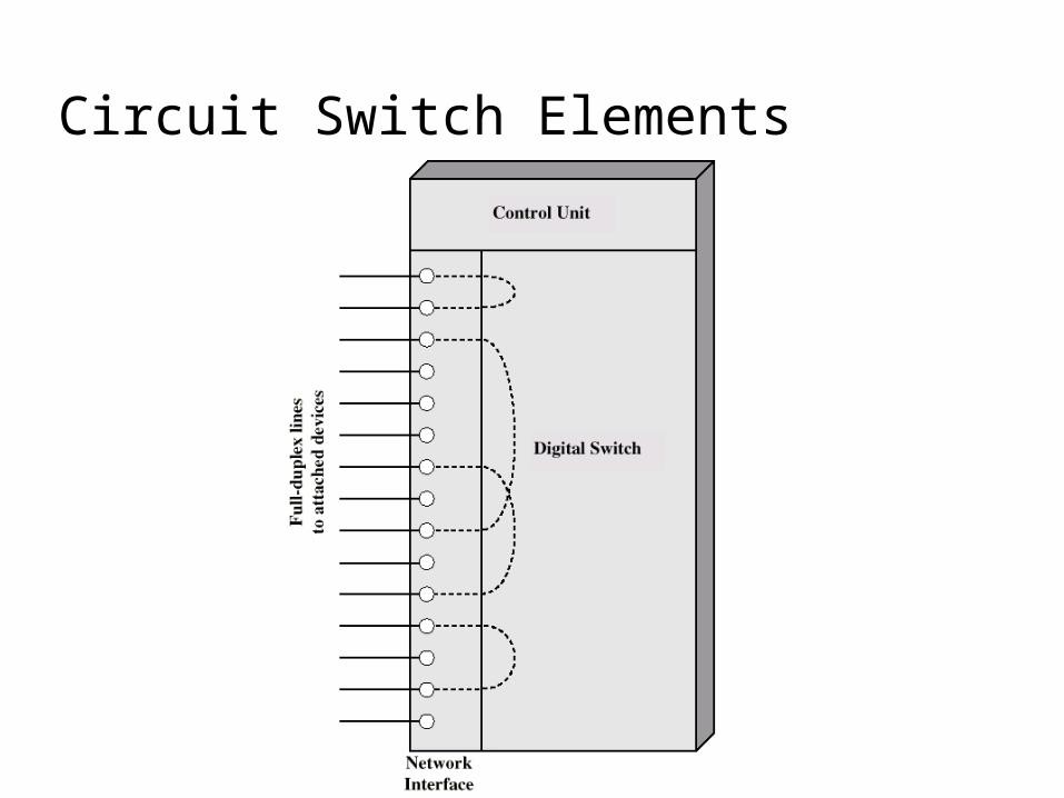
Circuit Switch Elements
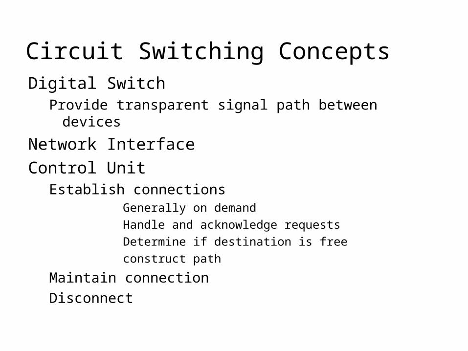
Circuit Switching ConceptsDigital Switch
Provide transparent signal path between devices
Network InterfaceControl Unit
Establish connectionsGenerally on demandHandle and acknowledge requestsDetermine if destination is freeconstruct path
Maintain connectionDisconnect
Blocking or Non-blockingBlocking
A network is unable to connect stations because all paths are in use
A blocking network allows thisUsed on voice systems
Short duration calls
Non-blockingPermits all stations to connect (in pairs) at onceUsed for some data connections
Space Division SwitchingDeveloped for analog environmentSeparate physical pathsCrossbar switch
Number of crosspoints grows as square of number of stations
Loss of crosspoint prevents connectionInefficient use of crosspoints
All stations connected, only a few crosspoints in use
Non-blocking
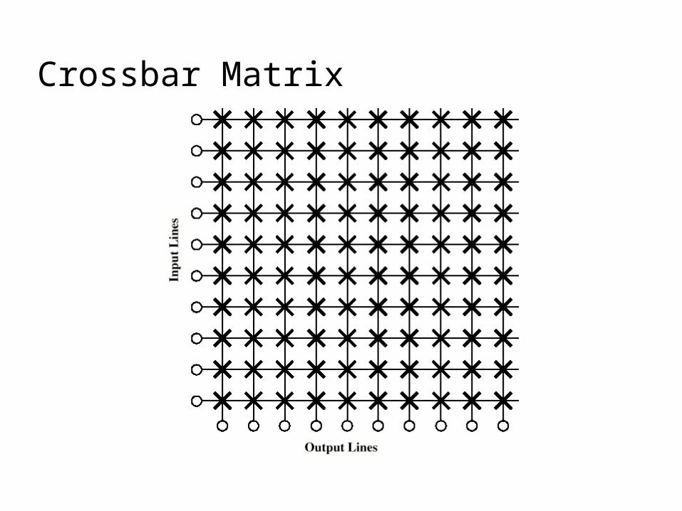
Crossbar Matrix
Multistage SwitchReduced number of crosspointsMore than one path through network
Increased reliability
More complex controlMay be blocking
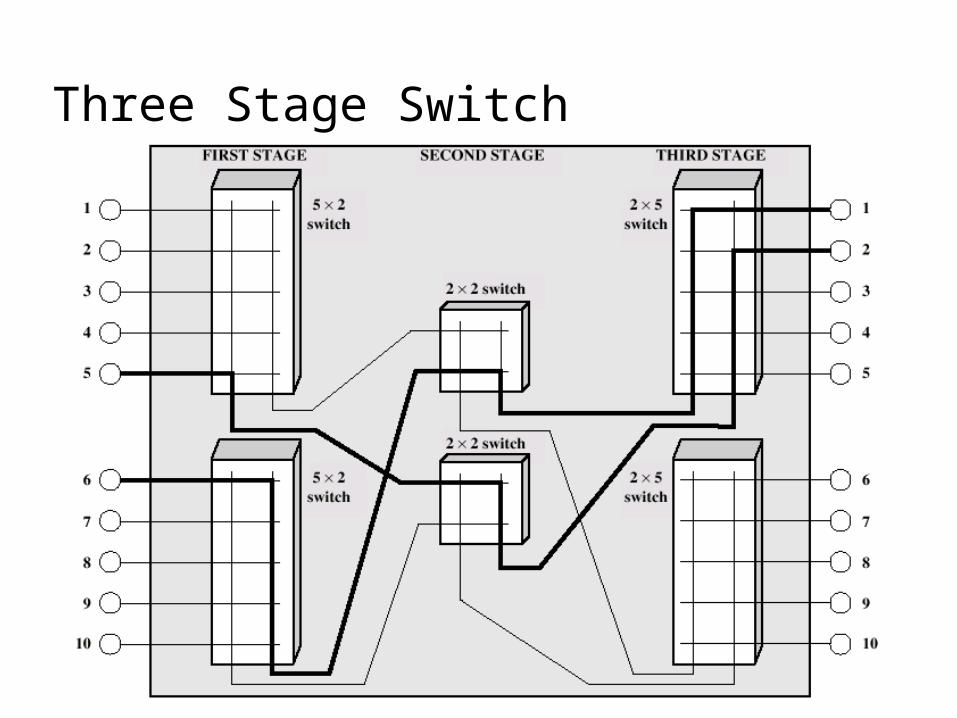
Three Stage Switch
Time Division SwitchingPartition low speed bit stream into pieces
that share higher speed streame.g. TDM bus switching
based on synchronous time division multiplexingEach station connects through controlled gates
to high speed busTime slot allows small amount of data onto busAnother line’s gate is enabled for output at the
same time
RoutingMany connections will need paths through
more than one switchNeed to find a route
EfficiencyResilience
Public telephone switches are a tree structureStatic routing uses the same approach all the time
Dynamic routing allows for changes in routing depending on trafficUses a peer structure for nodes
Alternate RoutingPossible routes between end offices
predefinedOriginating switch selects appropriate routeRoutes listed in preference orderDifferent sets of routes may be used at
different times
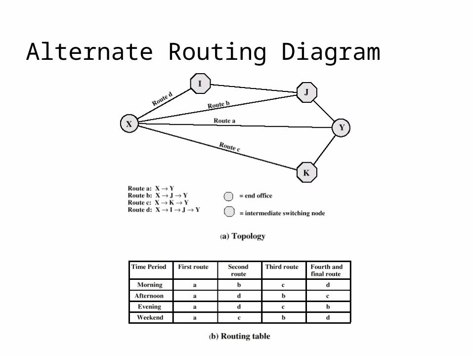
Alternate Routing Diagram
Control Signaling FunctionsAudible communication with subscriberTransmission of dialed numberCall can not be completed indicationCall ended indicationSignal to ring phoneBilling infoEquipment and trunk status infoDiagnostic infoControl of specialist equipment
Control Signal SequenceBoth phones on hookSubscriber lifts receiver (off hook)End office switch signaledSwitch responds with dial toneCaller dials numberIf target not busy, send ringer signal to target subscriberFeedback to caller
Ringing tone, engaged tone, unobtainable
Target accepts call by lifting receiverSwitch terminates ringing signal and ringing toneSwitch establishes connectionConnection release when Source subscriber hangs up
Switch to Switch SignalingSubscribers connected to different switchesOriginating switch seizes interswitch trunkSend off hook signal on trunk, requesting
digit register at target switch (for address)Terminating switch sends off hook followed
by on hook (wink) to show register readyOriginating switch sends address
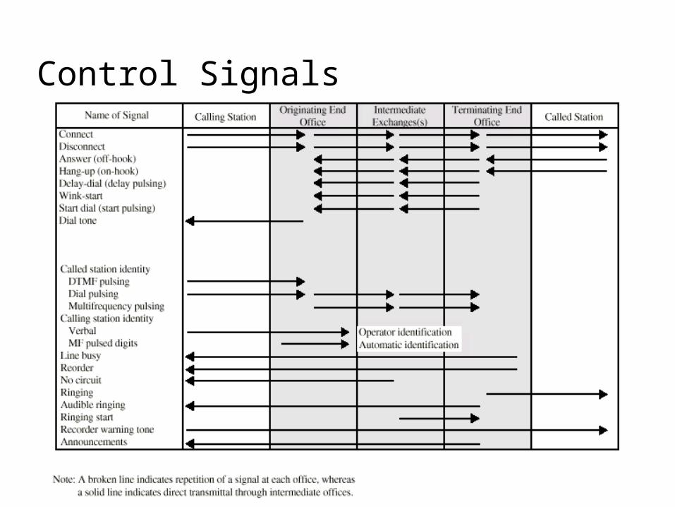
Control Signals
Location of SignalingSubscriber to network
Depends on subscriber device and switch
Within networkManagement of subscriber calls and networkore complex
In Channel SignalingUse same channel for signaling and call
Requires no additional transmission facilities
InbandUses same frequencies as voice signalCan go anywhere a voice signal canImpossible to set up a call on a faulty speech path
Out of bandVoice signals do not use full 4kHz bandwidthNarrow signal band within 4kHz used for controlCan be sent whether or not voice signals are presentNeed extra electronicsSlower signal rate (narrow bandwidth)
Drawbacks of In Channel SignalingLimited transfer rateDelay between entering address (dialing)
and connectionOvercome by use of common channel
signaling
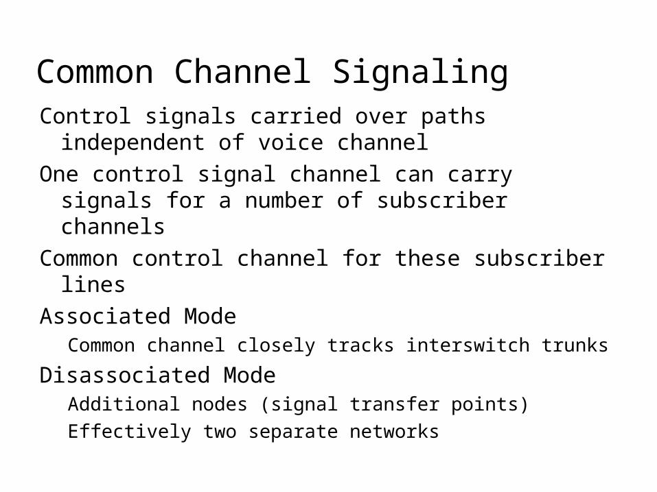
Common Channel SignalingControl signals carried over paths
independent of voice channelOne control signal channel can carry signals
for a number of subscriber channelsCommon control channel for these subscriber
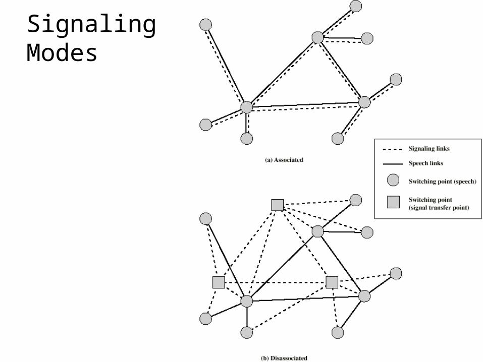
linesAssociated Mode
Common channel closely tracks interswitch trunks
Disassociated ModeAdditional nodes (signal transfer points)Effectively two separate networks
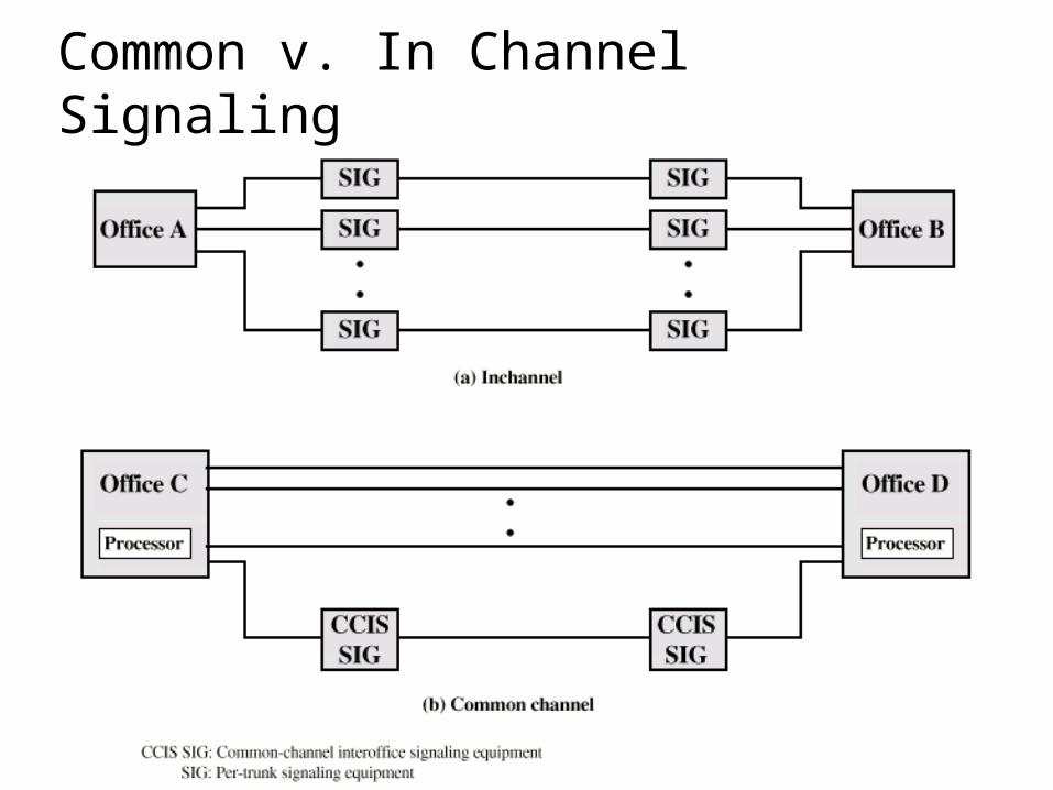
Common v. In Channel Signaling
Signaling Modes
Signaling System Number 7SS7Most widely used common channel signaling
schemeInternationally standardized and general
purpose
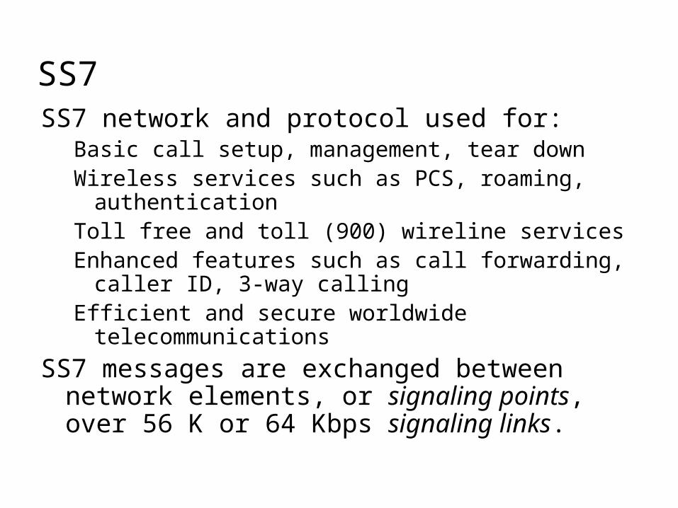
SS7SS7 network and protocol used for:
Basic call setup, management, tear downWireless services such as PCS, roaming,
authenticationToll free and toll (900) wireline servicesEnhanced features such as call forwarding, caller
ID, 3-way callingEfficient and secure worldwide
telecommunications
SS7 messages are exchanged between network elements, or signaling points, over 56 K or 64 Kbps signaling links.
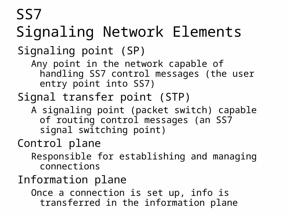
SS7 Signaling Network ElementsSignaling point (SP)
Any point in the network capable of handling SS7 control messages (the user entry point into SS7)
Signal transfer point (STP)A signaling point (packet switch) capable of
routing control messages (an SS7 signal switching point)
Control planeResponsible for establishing and managing
connections
Information planeOnce a connection is set up, info is transferred in
the information plane
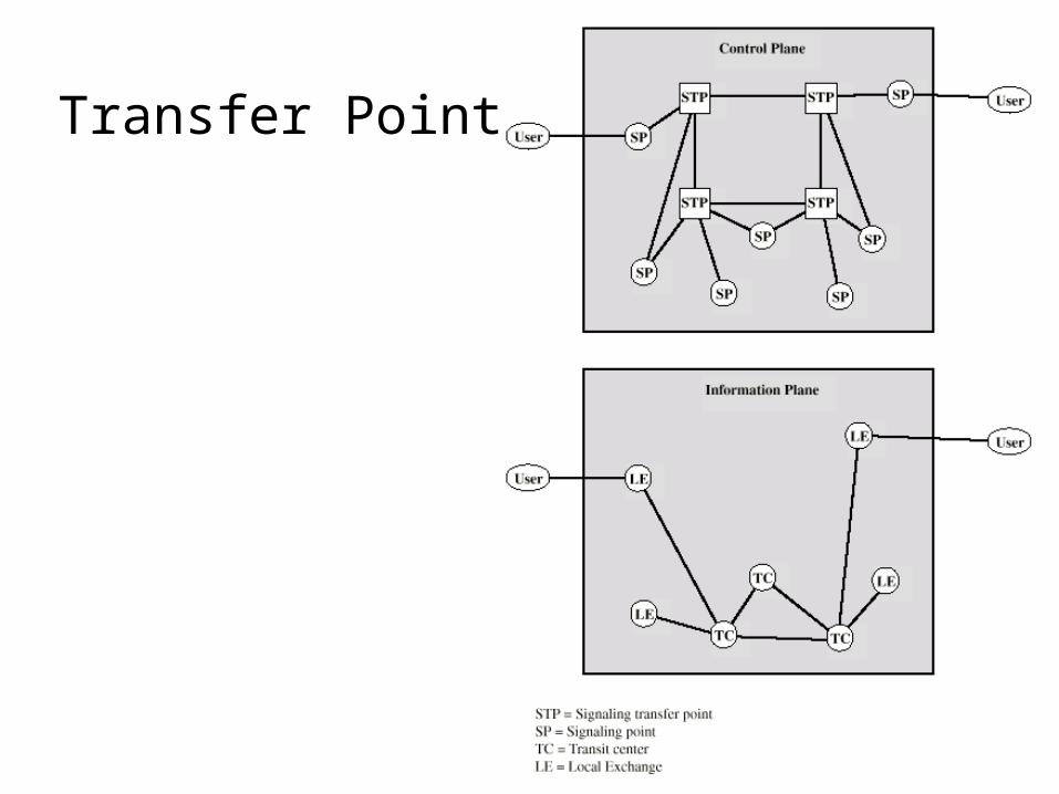
Transfer Points
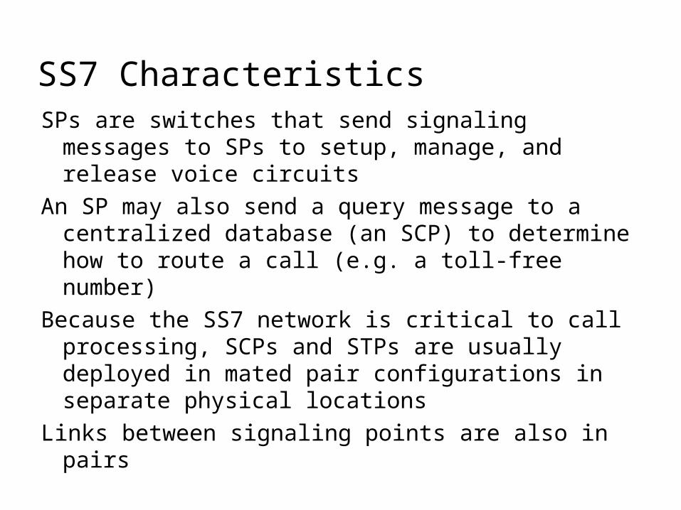
SS7 CharacteristicsSPs are switches that send signaling
messages to SPs to setup, manage, and release voice circuits
An SP may also send a query message to a centralized database (an SCP) to determine how to route a call (e.g. a toll-free number)
Because the SS7 network is critical to call processing, SCPs and STPs are usually deployed in mated pair configurations in separate physical locations
Links between signaling points are also in pairs
Review Questions1. What is the difference between node and
station?2. What are the advantages of a circuit
switched network? Disadvantages?3. What is a non-blocking switch?4. What is a crossbar? A multi-stage switch?
A time division switch?5. What is the difference between in
channel signaling and common channel signaling?
6. What are the basic components of SS7?