Embed Size (px)
Citation preview
Data Networks 1
Data Communication NetworksPhysical Layer
M. R. Pakravan
Department of Electrical Engineering
Sharif University of Technology
Data Communication Networks 2
Physical Layer Maximum Data Rate of a band
limited noiseless channel:C=2W*log2(V) bits/secwhere V is number of discrete signal levels, W is channel bandwidth
For Noisy channels:C=Wlog2(1+SNR) bits/sec
Example: A channel with a bandwidth of 4kHz and SNR=30dB can carry 40kbps at most
Important communication Media: Guided Transmission Media
Twisted Pair
Coaxial Cable
Power Lines
Fiber Optics
Wireless Transmission Radio/Microwave Transmission
Millimeter Wave Transmission
Light wave Transmission
Satellite Communication Geostationary
Medium Orbit Satellites
Low Earth Orbit Satellites
Data Communication Networks 3
0 200 400 600 800 1000 1200-40
-30
-20
-10
0Loop Length:4(kft) BT Length:0.7503(kft) BT distance from ATU-C:0.5(kft)
Frequency (kHz) |H
(f)|
(dB
)
|Hplain
(f)||H
BT(f)|
0 200 400 600 800 1000 1200-10
-8
-6
-4
-2
0
Frequency (kHz)
|HB
T(f)|-|
Hpl
ain(f)
| (dB
)
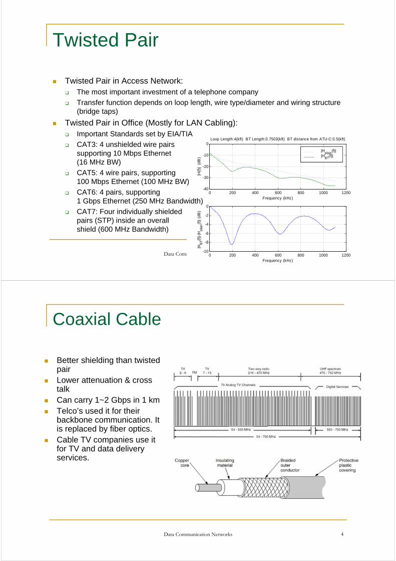
Twisted Pair
Twisted Pair in Access Network: The most important investment of a telephone company
Transfer function depends on loop length, wire type/diameter and wiring structure (bridge taps)
Twisted Pair in Office (Mostly for LAN Cabling): Important Standards set by EIA/TIA
CAT3: 4 unshielded wire pairs supporting 10 Mbps Ethernet (16 MHz BW)
CAT5: 4 wire pairs, supporting 100 Mbps Ethernet (100 MHz BW)
CAT6: 4 pairs, supporting 1 Gbps Ethernet (250 MHz Bandwidth)
CAT7: Four individually shielded pairs (STP) inside an overall shield (600 MHz Bandwidth)
Data Communication Networks 4
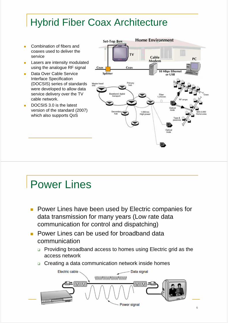
Coaxial Cable
Better shielding than twisted pair
Lower attenuation & cross talk
Can carry 1~2 Gbps in 1 km Telco’s used it for their
backbone communication. It is replaced by fiber optics.
Cable TV companies use it for TV and data delivery services.
Data Communication Networks 5
Hybrid Fiber Coax Architecture
Combination of fibers and coaxes used to deliver the service
Lasers are intensity modulated using the analogue RF signal
Data Over Cable Service Interface Specification (DOCSIS) series of standards were developed to allow data service delivery over the TV cable network.
DOCSIS 3.0 is the latest version of the standard (2007) which also supports QoS
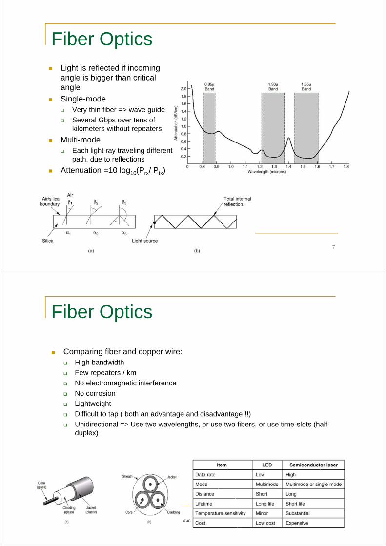
Power Lines
Power Lines have been used by Electric companies for data transmission for many years (Low rate data communication for control and dispatching)
Power Lines can be used for broadband data communication Providing broadband access to homes using Electric grid as the
access network
Creating a data communication network inside homes
Data Communication Networks 6
Data Communication Networks 7
Fiber Optics Light is reflected if incoming
angle is bigger than critical angle
Single-mode Very thin fiber => wave guide
Several Gbps over tens of kilometers without repeaters
Multi-mode Each light ray traveling different
path, due to reflections
Attenuation =10 log10(Prx/ Ptx)
Data Communication Networks 8
Fiber Optics
Comparing fiber and copper wire: High bandwidth
Few repeaters / km
No electromagnetic interference
No corrosion
Lightweight
Difficult to tap ( both an advantage and disadvantage !!)
Unidirectional => Use two wavelengths, or use two fibers, or use time-slots (half-duplex)
Data Communication Networks 9
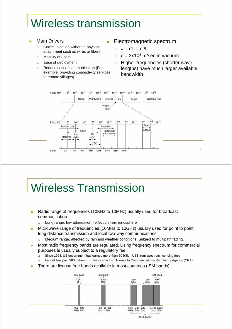
Wireless transmission Main Drivers
Communication without a physical attachment such as wires or fibers.
Mobility of users
Ease of deployment
Reduce cost of communication (For example, providing connectivity services to remote villages)
Electromagnetic spectrum = c = c /f
c = 3x10⁸ m/sec in vacuum
Higher frequencies (shorter wave lengths) have much larger available bandwidth
Data Communication Networks 10
Wireless Transmission
Radio range of frequencies (10KHz to 10MHz) usually used for broadcast communication Long range, low attenuation, reflection from ionosphere
Microwave range of frequencies (10MHz to 10GHz) usually used for point to point long distance transmission and local two-way communications Medium range, affected by rain and weather conditions. Subject to multipath fading.
Most radio frequency bands are regulated. Using frequency spectrum for commercial purposes is usually subject to a regulatory fee. Since 1994, US government has earned more than 60 billion US$ from spectrum licensing fees
Irancell has paid 300 million Euro for its spectrum license to Communications Regulatory Agency (CRA)
There are license free bands available in most countries (ISM bands)
Data Communication Networks 11
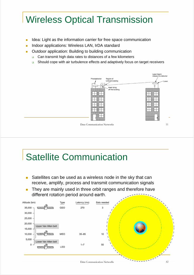
Wireless Optical Transmission
Idea: Light as the information carrier for free space communication
Indoor applications: Wireless LAN, IrDA standard
Outdoor application: Building to building communication Can transmit high data rates to distances of a few kilometers
Should cope with air turbulence effects and adaptively focus on target receivers
Satellite Communication
Satellites can be used as a wireless node in the sky that can receive, amplify, process and transmit communication signals
They are mainly used in three orbit ranges and therefore have different rotation period around earth.
Data Communication Networks 12
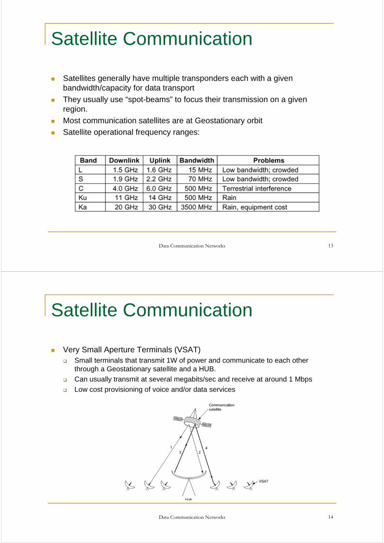
Satellite Communication
Satellites generally have multiple transponders each with a given bandwidth/capacity for data transport
They usually use “spot-beams” to focus their transmission on a given region.
Most communication satellites are at Geostationary orbit
Satellite operational frequency ranges:
Data Communication Networks 13
Satellite Communication
Very Small Aperture Terminals (VSAT) Small terminals that transmit 1W of power and communicate to each other
through a Geostationary satellite and a HUB.
Can usually transmit at several megabits/sec and receive at around 1 Mbps
Low cost provisioning of voice and/or data services
Data Communication Networks 14
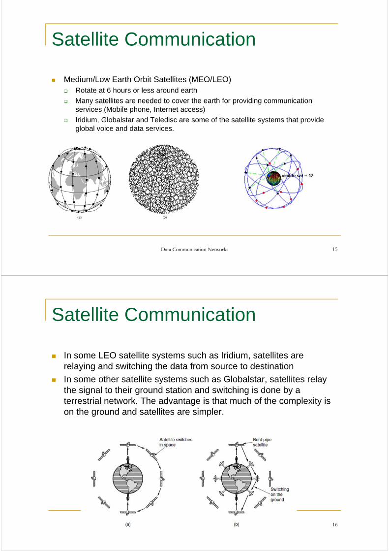
Satellite Communication
Medium/Low Earth Orbit Satellites (MEO/LEO) Rotate at 6 hours or less around earth
Many satellites are needed to cover the earth for providing communication services (Mobile phone, Internet access)
Iridium, Globalstar and Teledisc are some of the satellite systems that provide global voice and data services.
Data Communication Networks 15
Satellite Communication
In some LEO satellite systems such as Iridium, satellites are relaying and switching the data from source to destination
In some other satellite systems such as Globalstar, satellites relay the signal to their ground station and switching is done by a terrestrial network. The advantage is that much of the complexity is on the ground and satellites are simpler.
Data Communication Networks 16
Satellites Versus Fiber
Optical communication is the dominant technology for transmission of data.
From office LANs to intercontinental communication networks, optical communication systems are used as a cost effective solution.
Satellite communication serves some key demands Networks that require rapid deployment (disaster recovery, military
applications)
Communication in places where terrestrial networks are not well developed (jungles, countries with many islands, oil stations in the sea)
Broadcasting (TV, Radio)
Data Communication Networks 17
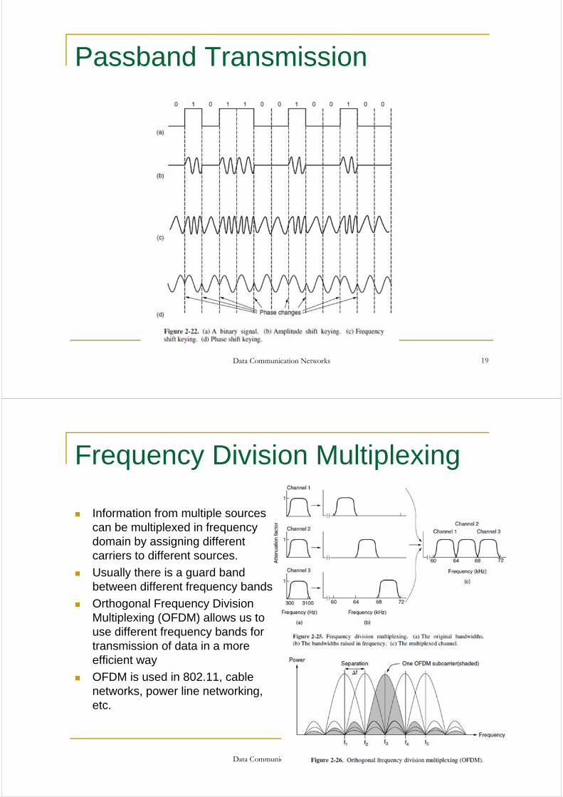
Baseband Transmission
Data Communication Networks 18
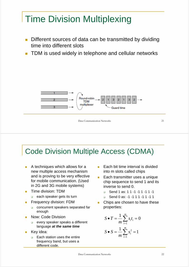
Passband Transmission
Data Communication Networks 19
Frequency Division Multiplexing
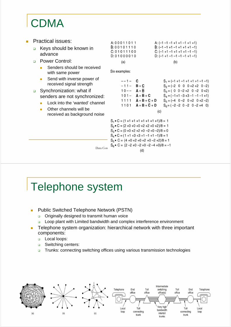
Information from multiple sources can be multiplexed in frequency domain by assigning different carriers to different sources.
Usually there is a guard band between different frequency bands
Orthogonal Frequency Division Multiplexing (OFDM) allows us to use different frequency bands for transmission of data in a more efficient way
OFDM is used in 802.11, cable networks, power line networking, etc.
Data Communication Networks 20
Time Division Multiplexing
Different sources of data can be transmitted by dividing time into different slots
TDM is used widely in telephone and cellular networks
Data Communication Networks 21
Data Communication Networks 22
Code Division Multiple Access (CDMA)
A techniques which allows for a new multiple access mechanism and is proving to be very effective for mobile communication. (Used in 2G and 3G mobile systems)
Time division: TDM each speaker gets its turn
Frequency division: FDM concurrent speakers separated far
enough
Now: Code Division every speaker speaks a different
language at the same time
Key idea: Each station uses the entire
frequency band, but uses a different code.
Each bit time interval is divided into m slots called chips
Each transmitter uses a unique chip sequence to send 1 and its inverse to send 0. Send 1 as: 1 1 -1 -1 1 -1 1 -1
Send 0 as: -1 -1 1 1 -1 1 -1 1
Chips are chosen to have these properties:
11
01
1
2
1
m
ii
m
iii
sm
SS
tsm
TS
Data Communication Networks 23
CDMA
Practical issues: Keys should be known in
advance
Power Control: Senders should be received
with same power
Send with inverse power of received signal strength
Synchronization: what if senders are not synchronized: Lock into the ‘wanted’ channel
Other channels will be received as background noise
Data Communication Networks 24
Telephone system
Public Switched Telephone Network (PSTN) Originally designed to transmit human voice Loop plant with Limited bandwidth and complex interference environment
Telephone system organization: hierarchical network with three important components: Local loops: Switching centers: Trunks: connecting switching offices using various transmission technologies
Data Communication Networks 25
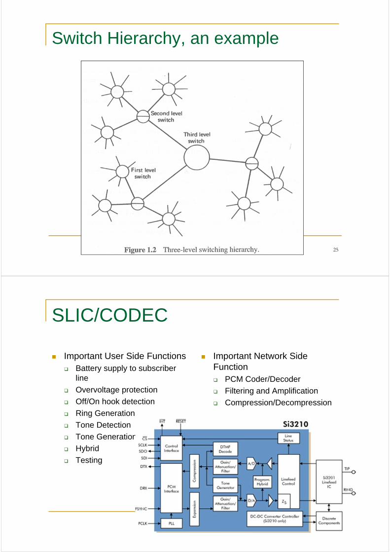
Switch Hierarchy, an example
SLIC/CODEC
Important User Side Functions Battery supply to subscriber
line
Overvoltage protection
Off/On hook detection
Ring Generation
Tone Detection
Tone Generation
Hybrid
Testing
Important Network Side Function PCM Coder/Decoder
Filtering and Amplification
Compression/Decompression
Data Communication Networks 26
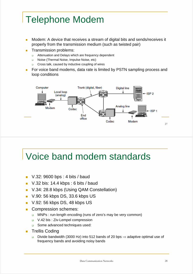
Telephone Modem
Modem: A device that receives a stream of digital bits and sends/receives it properly from the transmission medium (such as twisted pair)
Transmission problems: Attenuation and Delays which are frequency dependent
Noise (Thermal Noise, Impulse Noise, etc)
Cross talk, caused by inductive coupling of wires
For voice band modems, data rate is limited by PSTN sampling process and loop conditions
Data Communication Networks 27
Voice band modem standards
V.32: 9600 bps : 4 bits / baud
V.32 bis: 14.4 kbps : 6 bits / baud
V.34: 28.8 kbps (Using QAM Constellation)
V.90: 56 kbps DS, 33.6 kbps US
V.92: 56 kbps DS, 48 kbps US
Compression schemes: MNPs : run-length encoding (runs of zero’s may be very common)
V.42 bis : Ziv-Lempel compression
Some advanced techniques used:
Trellis Coding Divide bandwidth (3000 Hz) into 512 bands of 20 bps adaptive optimal use of
frequency bands and avoiding noisy bands
Data Communication Networks 28
Data Communication Networks 29
Local Loop, Broadband Access -ADSL
Objective: Offering data services without impacting the voice service on twisted pair
Central Office (CO) side: Use splitter to feed low pass part to
the voice switch while the higher frequencies to the feed the DSLAM
Customer Premise End (CPE) Use splitter or in-line filters to feed
the low pass part of the spectrum to the telephone and the high pass part to the CPE ADSL modem
ADSL signal power spectrum is defined carefully to reduce cross talk into other services
Data Communication Networks 30
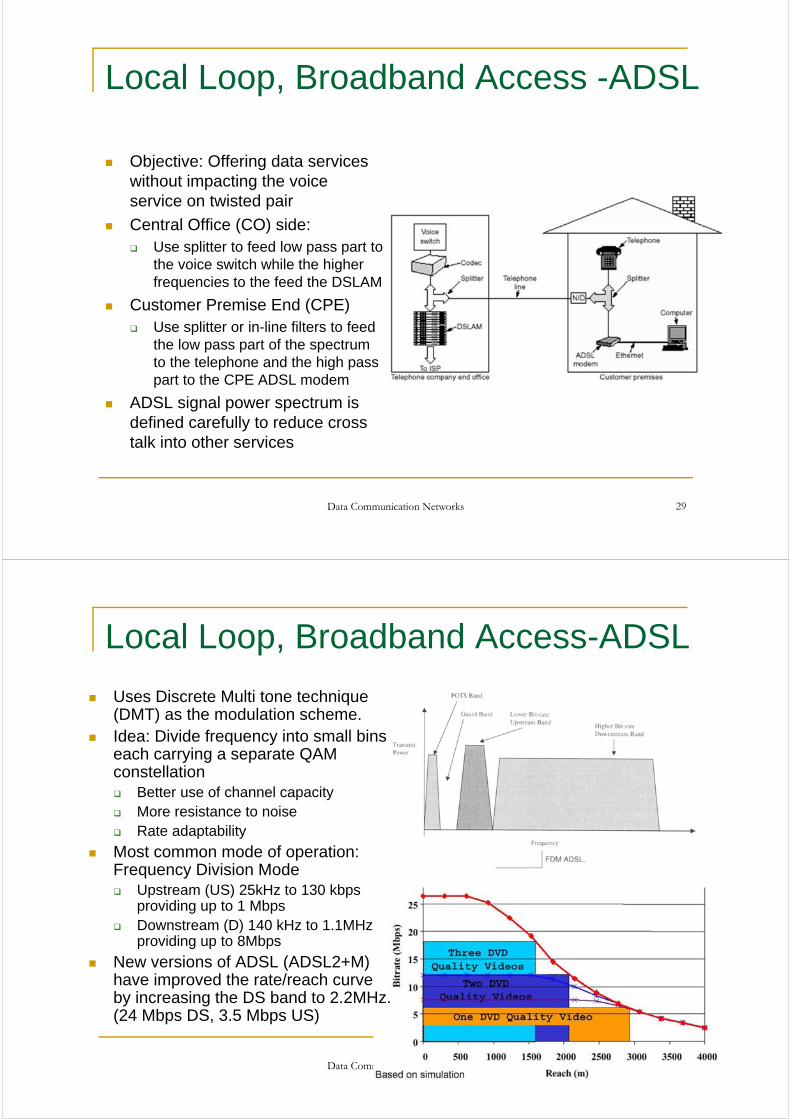
Local Loop, Broadband Access-ADSL
Uses Discrete Multi tone technique (DMT) as the modulation scheme.
Idea: Divide frequency into small bins each carrying a separate QAM constellation Better use of channel capacity More resistance to noise Rate adaptability
Most common mode of operation: Frequency Division Mode Upstream (US) 25kHz to 130 kbps
providing up to 1 Mbps Downstream (D) 140 kHz to 1.1MHz
providing up to 8Mbps
New versions of ADSL (ADSL2+M) have improved the rate/reach curve by increasing the DS band to 2.2MHz. (24 Mbps DS, 3.5 Mbps US)
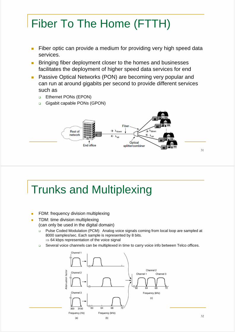
Fiber To The Home (FTTH)
Fiber optic can provide a medium for providing very high speed data services.
Bringing fiber deployment closer to the homes and businesses facilitates the deployment of higher speed data services for end
Passive Optical Networks (PON) are becoming very popular and can run at around gigabits per second to provide different services such as Ethernet PONs (EPON)
Gigabit capable PONs (GPON)
Data Communication Networks 31
Trunks and Multiplexing
FDM: frequency division multiplexing
TDM: time division multiplexing(can only be used in the digital domain) Pulse Coded Modulation (PCM): Analog voice signals coming from local loop are sampled at
8000 samples/sec. Each sample is represented by 8 bits. 64 kbps representation of the voice signal
Several voice channels can be multiplexed in time to carry voice info between Telco offices.
Data Communication Networks 32
Data Communication Networks 33
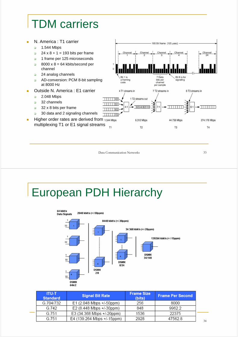
TDM carriers N. America : T1 carrier
1.544 Mbps
24 x 8 + 1 = 193 bits per frame
1 frame per 125 microseconds
8000 x 8 = 64 kbits/second per channel
24 analog channels
AD-conversion: PCM 8-bit sampling at 8000 Hz
Outside N. America : E1 carrier 2.048 Mbps
32 channels
32 x 8 bits per frame
30 data and 2 signaling channels
Higher order rates are derived from multiplexing T1 or E1 signal streams
European PDH Hierarchy
Data Communication Networks 34
Data Communication Networks 35
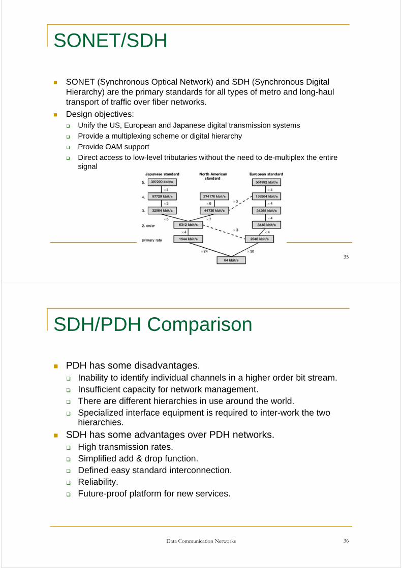
SONET/SDH
SONET (Synchronous Optical Network) and SDH (Synchronous Digital Hierarchy) are the primary standards for all types of metro and long-haul transport of traffic over fiber networks.
Design objectives: Unify the US, European and Japanese digital transmission systems
Provide a multiplexing scheme or digital hierarchy
Provide OAM support
Direct access to low-level tributaries without the need to de-multiplex the entire signal
Data Communication Networks 36
SDH/PDH Comparison
PDH has some disadvantages. Inability to identify individual channels in a higher order bit stream. Insufficient capacity for network management. There are different hierarchies in use around the world. Specialized interface equipment is required to inter-work the two
hierarchies.
SDH has some advantages over PDH networks. High transmission rates. Simplified add & drop function. Defined easy standard interconnection. Reliability. Future-proof platform for new services.
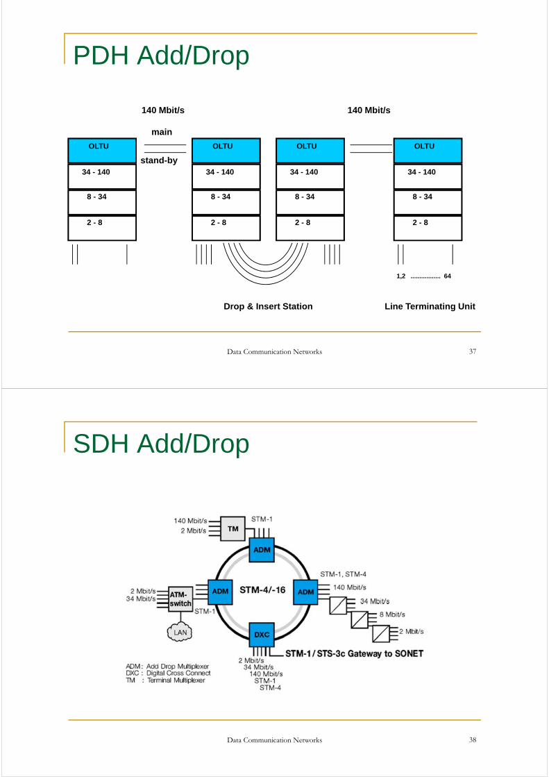
PDH Add/Drop
Data Communication Networks 37
OLTU
34 - 140
8 - 34
2 - 8
OLTU
34 - 140
8 - 34
2 - 8
OLTU
34 - 140
8 - 34
2 - 8
OLTU
34 - 140
8 - 34
2 - 8
main
stand-by
140 Mbit/s 140 Mbit/s
Line Terminating UnitDrop & Insert Station
1,2 ................. 64
SDH Add/Drop
Data Communication Networks 38
Data Communication Networks 39
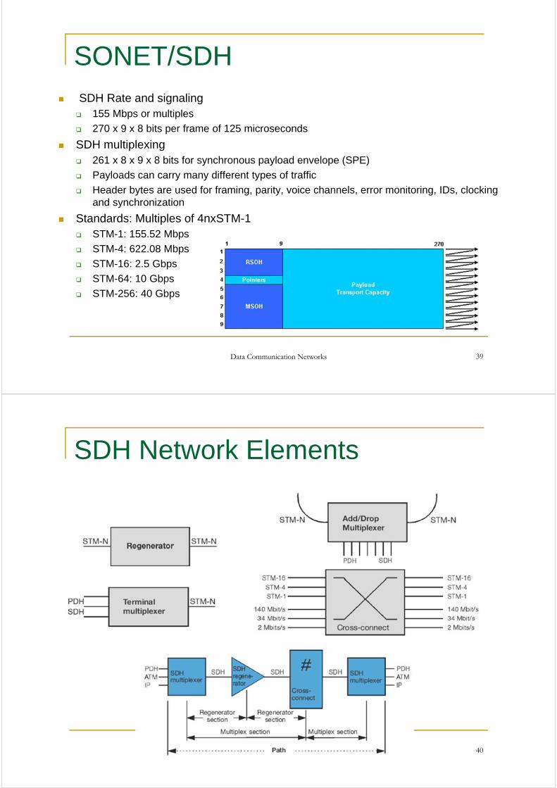
SONET/SDH SDH Rate and signaling
155 Mbps or multiples
270 x 9 x 8 bits per frame of 125 microseconds
SDH multiplexing 261 x 8 x 9 x 8 bits for synchronous payload envelope (SPE)
Payloads can carry many different types of traffic
Header bytes are used for framing, parity, voice channels, error monitoring, IDs, clocking and synchronization
Standards: Multiples of 4nxSTM-1 STM-1: 155.52 Mbps
STM-4: 622.08 Mbps
STM-16: 2.5 Gbps
STM-64: 10 Gbps
STM-256: 40 Gbps
Data Communication Networks 40
SDH Network Elements
Data Communication Networks 41
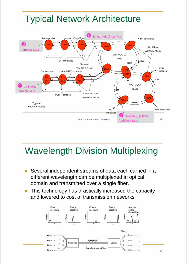
Typical Network Architecture
1+1 APS
Terminal Mux
Typical Network Nodes
TM ADM ADM
PDH Tributaries
Terminal Mux Linear Add/Drop Muxes
Dual-Ring
Add/Drop Muxes
Standard
STM-1/OC-3 Link
1+1
TM
1+1
ADM
1+1
ADM
Terminal Mux Linear Add/Drop Muxes
CCW
CWCCW
ADM ADM
ADM
ADM
PDH Tributaries
PDH Tributaries
STM-1/OC-3
RING
Linear 1+1 APS
STM-1/OC-3 Link
ADM
ADMADM
CW
PDH Tributaries
Ring
Bridge
PDH TributariesPDH Tributaries
Linear Add/Drop Mux
Dual Ring (UPSR)
Add/Drop Mux
Terminal Mux
STM-4/OC-12
RING
Wavelength Division Multiplexing
Several independent streams of data each carried in a different wavelength can be multiplexed in optical domain and transmitted over a single fiber.
This technology has drastically increased the capacity and lowered to cost of transmission networks
Data Communication Networks 43
Data Communication Networks 44
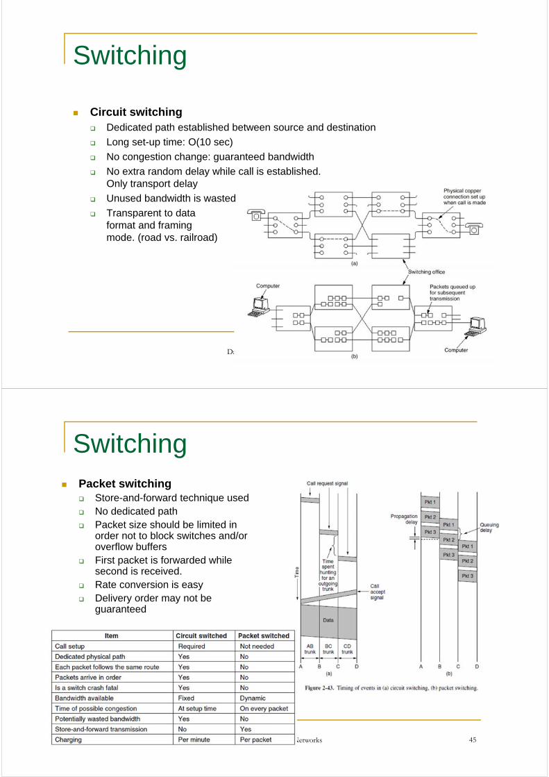
Switching
Circuit switching Dedicated path established between source and destination
Long set-up time: O(10 sec)
No congestion change: guaranteed bandwidth
No extra random delay while call is established. Only transport delay
Unused bandwidth is wasted
Transparent to data format and framing mode. (road vs. railroad)
Data Communication Networks 45
Switching Packet switching
Store-and-forward technique used No dedicated path Packet size should be limited in
order not to block switches and/or overflow buffers
First packet is forwarded while second is received.
Rate conversion is easy Delivery order may not be
guaranteed
Data Communication Networks 46
Mobile Phone System
Mobile Phone Evolution First Gen: Analog Voice Second Gen: Digital Voice Third Gen: Digital Voice and Data Fourth Gen: Mainly Data
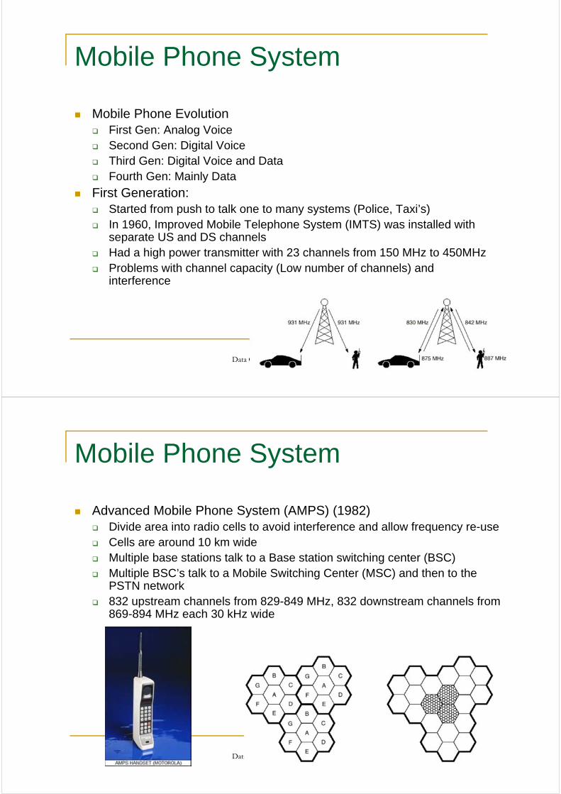
First Generation: Started from push to talk one to many systems (Police, Taxi’s) In 1960, Improved Mobile Telephone System (IMTS) was installed with
separate US and DS channels Had a high power transmitter with 23 channels from 150 MHz to 450MHz Problems with channel capacity (Low number of channels) and
interference
Data Communication Networks 47
Mobile Phone System
Advanced Mobile Phone System (AMPS) (1982) Divide area into radio cells to avoid interference and allow frequency re-use Cells are around 10 km wide Multiple base stations talk to a Base station switching center (BSC) Multiple BSC’s talk to a Mobile Switching Center (MSC) and then to the
PSTN network 832 upstream channels from 829-849 MHz, 832 downstream channels from
869-894 MHz each 30 kHz wide
Data Communication Networks 48
Mobile Phone System
Channels are used for Control (Base to Mobile) to
manage the system (21 channels)
Paging (Base to Mobile) to alert mobile users for a call
Access (Bi-directional) for call setup and channel assignment
Data (Bi-directional) for voice, fax and data (usually around 45 channels due to frequency re-use)
Call handling When handset is powered on, it scans
control channels to find the most powerful signal
It then broadcasts its 32 bit serial number and phone number in digital format
BTS reports to MSC and it will decide if the user should be accepted for service
When mobile is dialing, MSC decides upon the channel and service availability and connects the call
MSC should also handle roaming and handoff
For incoming call, handset should continuously monitor the paging channel and respond through the control channel when a call request comes in
Data Communication Networks 49
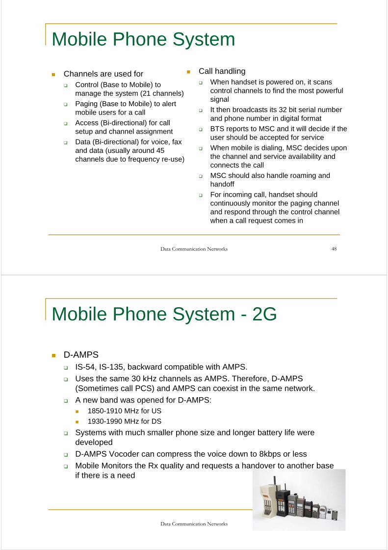
Mobile Phone System - 2G
D-AMPS IS-54, IS-135, backward compatible with AMPS.
Uses the same 30 kHz channels as AMPS. Therefore, D-AMPS (Sometimes call PCS) and AMPS can coexist in the same network.
A new band was opened for D-AMPS: 1850-1910 MHz for US
1930-1990 MHz for DS
Systems with much smaller phone size and longer battery life were developed
D-AMPS Vocoder can compress the voice down to 8kbps or less
Mobile Monitors the Rx quality and requests a handover to another base if there is a need
50
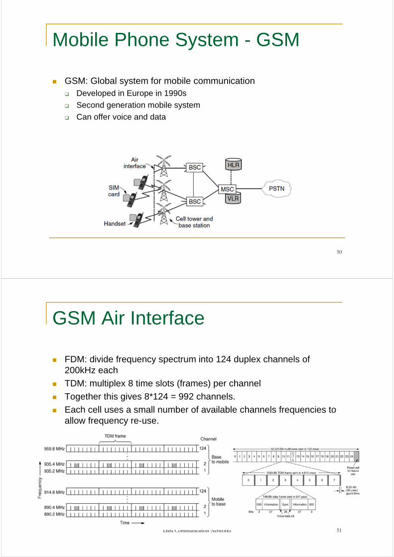
Mobile Phone System - GSM
GSM: Global system for mobile communication Developed in Europe in 1990s
Second generation mobile system
Can offer voice and data
Data Communication Networks 51
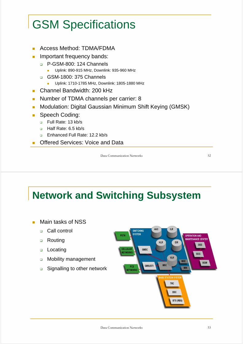
GSM Air Interface
FDM: divide frequency spectrum into 124 duplex channels of 200kHz each
TDM: multiplex 8 time slots (frames) per channel
Together this gives 8*124 = 992 channels.
Each cell uses a small number of available channels frequencies to allow frequency re-use.
GSM Specifications
Access Method: TDMA/FDMA
Important frequency bands: P-GSM-800: 124 Channels
Uplink: 890-915 MHz, Downlink: 935-960 MHz
GSM-1800: 375 Channels Uplink: 1710-1785 MHz, Downlink: 1805-1880 MHz
Channel Bandwidth: 200 kHz
Number of TDMA channels per carrier: 8
Modulation: Digital Gaussian Minimum Shift Keying (GMSK)
Speech Coding: Full Rate: 13 kb/s
Half Rate: 6.5 kb/s
Enhanced Full Rate: 12.2 kb/s
Offered Services: Voice and Data
Data Communication Networks 52
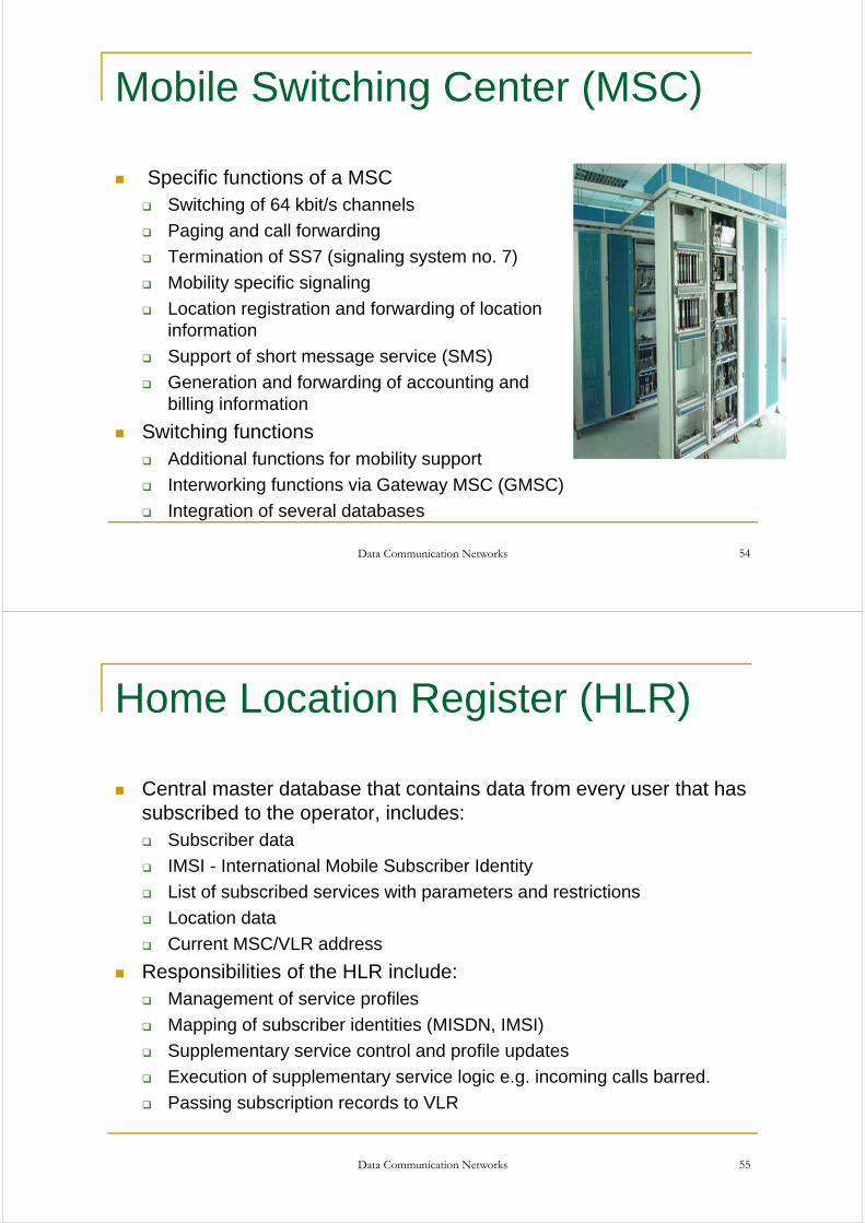
Network and Switching Subsystem
Main tasks of NSS
Call control
Routing
Locating
Mobility management
Signalling to other network
Data Communication Networks 53
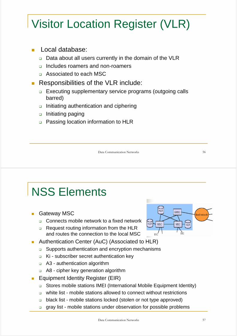
Mobile Switching Center (MSC)
Specific functions of a MSC Switching of 64 kbit/s channels
Paging and call forwarding
Termination of SS7 (signaling system no. 7)
Mobility specific signaling
Location registration and forwarding of location information
Support of short message service (SMS)
Generation and forwarding of accounting and billing information
Switching functions Additional functions for mobility support
Interworking functions via Gateway MSC (GMSC)
Integration of several databases
Data Communication Networks 54
Home Location Register (HLR)
Central master database that contains data from every user that has subscribed to the operator, includes: Subscriber data
IMSI - International Mobile Subscriber Identity
List of subscribed services with parameters and restrictions
Location data
Current MSC/VLR address
Responsibilities of the HLR include: Management of service profiles
Mapping of subscriber identities (MISDN, IMSI)
Supplementary service control and profile updates
Execution of supplementary service logic e.g. incoming calls barred.
Passing subscription records to VLR
Data Communication Networks 55
Visitor Location Register (VLR)
Local database: Data about all users currently in the domain of the VLR
Includes roamers and non-roamers
Associated to each MSC
Responsibilities of the VLR include: Executing supplementary service programs (outgoing calls
barred)
Initiating authentication and ciphering
Initiating paging
Passing location information to HLR
Data Communication Networks 56
NSS Elements
Gateway MSC Connects mobile network to a fixed network
Request routing information from the HLR and routes the connection to the local MSC
Authentication Center (AuC) (Associated to HLR) Supports authentication and encryption mechanisms
Ki - subscriber secret authentication key
A3 - authentication algorithm
A8 - cipher key generation algorithm
Equipment Identity Register (EIR) Stores mobile stations IMEI (International Mobile Equipment Identity)
white list - mobile stations allowed to connect without restrictions
black list - mobile stations locked (stolen or not type approved)
gray list - mobile stations under observation for possible problems
Data Communication Networks 57
Data Communication Networks 58
GSM Call Process GSM Channels:
Traffic Channels Signaling Channels
Signaling Channels: Broadcast channel for:
Outputting identity of base station Each mobile checks its signal strength to
see if it has moved to another cell Dedicated channel for:
Location updating Registration Call setup
Common Control channel for: Paging (of incoming calls); each mobile
monitors this channel Random access channel, using slotted
Aloha to request a slot on the dedicated channel, to set up a new call
Access grant channel
Setting up a call: Mobile requests a dedicated access
channel# using random access channel; this is the only channel where we can get collisions; so it is used very shortly
Base grants channel# on access grant channel
Setup the call on dedicated channel
Start the conversation on one of the agreed regular channels
Data Communication Networks 59
Third Generation Mobile Systems (3G)
Objectives: High quality voice High speed data for messaging,
multimedia and internet access. Up to 2 Mbps rate to fixed users
and up to 384 kbps to mobile users
Three main standards: Wideband CDMA
Developed mostly in Europe Runs in a 5 MHz band Can inter-work with GSM but not
backward compatible
CDMA2000 Developed mostly in USA Uses 5 MHz bandwidth Designed to interwork with IS-95
which is a 2G CDMA standard used in North America
TD-SCDMA Chinese version of 3G systems
Interim Standards and Technologies between 2G and 3G: General Packet Radio Service
(GPRS) An overlay packet network on top of
GSM or D-AMPS Slots are reserved for IP data traffic
based on demand.
Enhanced Data Rate for GSM (EDGE) Enhanced GSM with more data
rates Can provide up to 384 kbps of data
rate to users
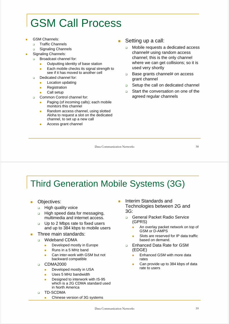
3G roll out
Data Communication Networks 60
Source: cellular-news.comJan 2009
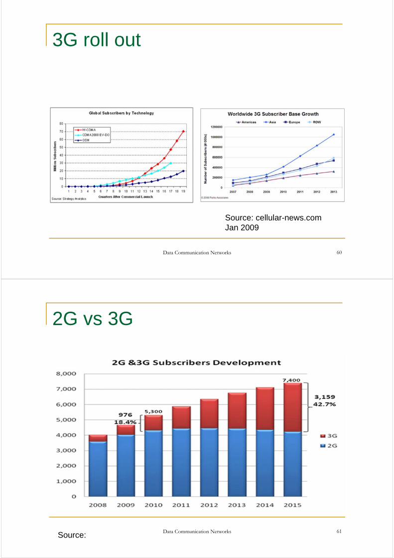
2G vs 3G
Data Communication Networks 61Source:
Data Communication Networks 62
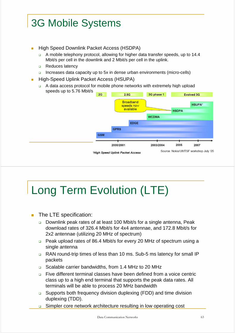
3G Mobile Systems
High Speed Downlink Packet Access (HSDPA) A mobile telephony protocol, allowing for higher data transfer speeds, up to 14.4
Mbit/s per cell in the downlink and 2 Mbit/s per cell in the uplink.
Reduces latency
Increases data capacity up to 5x in dense urban environments (micro-cells)
High-Speed Uplink Packet Access (HSUPA) A data access protocol for mobile phone networks with extremely high upload
speeds up to 5.76 Mbit/s.
Long Term Evolution (LTE)
The LTE specification: Downlink peak rates of at least 100 Mbit/s for a single antenna, Peak
download rates of 326.4 Mbit/s for 4x4 antennae, and 172.8 Mbit/s for 2x2 antennae (utilizing 20 MHz of spectrum)
Peak upload rates of 86.4 Mbit/s for every 20 MHz of spectrum using a single antenna
RAN round-trip times of less than 10 ms. Sub-5 ms latency for small IP packets
Scalable carrier bandwidths, from 1.4 MHz to 20 MHz
Five different terminal classes have been defined from a voice centric class up to a high end terminal that supports the peak data rates. All terminals will be able to process 20 MHz bandwidth
Supports both frequency division duplexing (FDD) and time division duplexing (TDD).
Simpler core network architecture resulting in low operating cost
Data Communication Networks 63
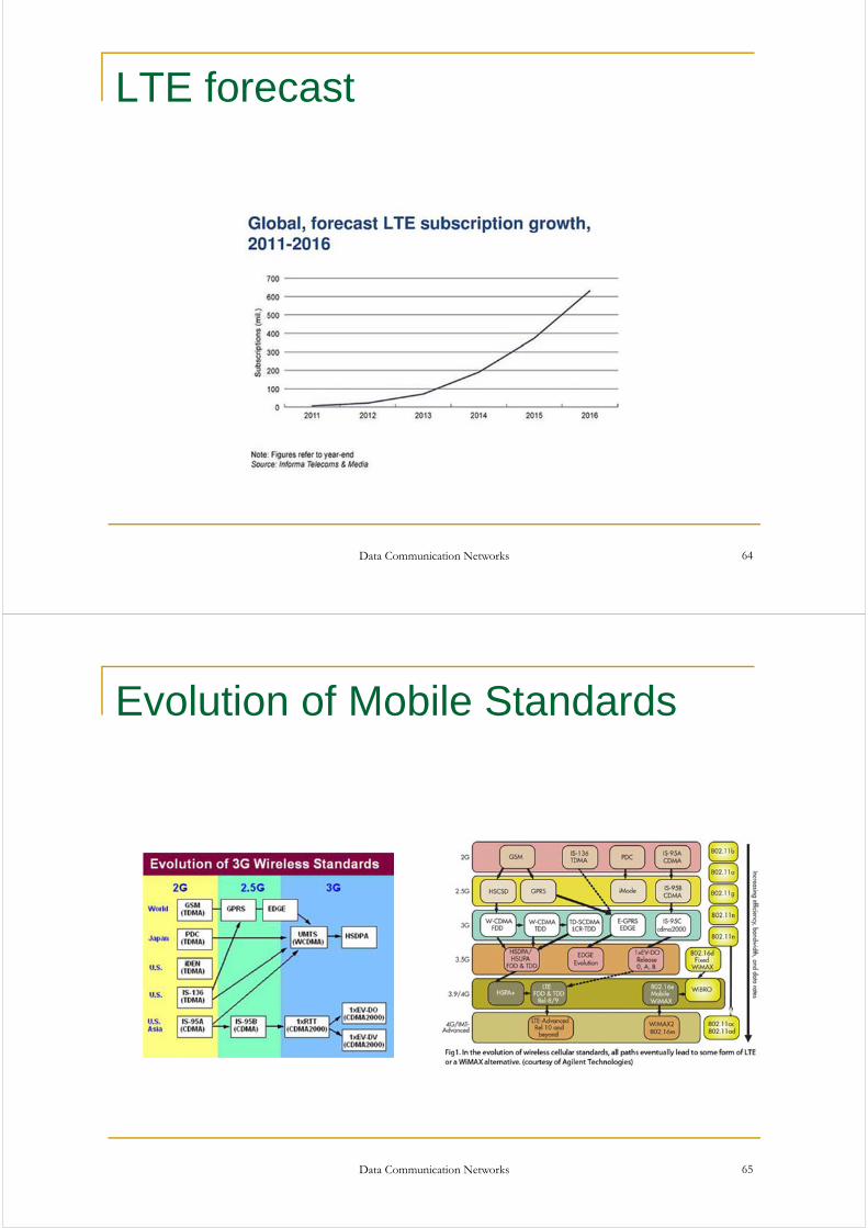
LTE forecast
Data Communication Networks 64
Evolution of Mobile Standards
Data Communication Networks 65