Embed Size (px)
Citation preview

Simple mainframe data centers have grown to full fledged Data Centers with a myriad of servers, stor-age, switching and routing options. As we continue to add equipment to these “rooms” we increasethe heat generation while reaching peak capacity. In order to maximize cooling efficiency within DataCenters there are best practices provided by organizations such as ASHRAE (American Society ofHeating, Refrigerating, and Air-Conditioning Engineers), which are followed or echoed in many of theindustry standards. While some seem to be common sense, others are sometimes neglected.
Data Center Cooling Best Practices:Maximizing power efficiency through smart planning and design
www.siemon.com
WP_DC_Cooling_C_B 8/13/13 1:47 PM Page 1

Addressing Cabling and Pathways
First, and most simply, in order to increase chiller efficiency, it is mandatory to get rid of the oldabandoned cabling under raised floors. While cable abatement is a code requirement in somecountries due to fuel loads, in all instances and all countries, it makes sense to remove blockageshaving an impact on air flow to equipment. While working on cable abatement strategies, it isa great time to look at upgrade projects to higher performing cabling which can be either whollyor partially funded through recycling of older copper cable.
While a properly designed under floor cable plant will not cause cooling inefficiencies, when theunder floor void is full of cable, a reverse vortex can be created causing the under floor void topull air from the room rather than push cool air up to the equipment. When pathways and spacesare properly designed, the cable trays can act as a baffle to help maintain the cold air in the coldaisles, or channel the air. Problems occur when there is little or no planning for pathways, Theybecome over filled as many years of abandoned cable fills the pathways and air voids. Overfillingpathways can also cause performance issues. In designing an under floor system, it is critical tolook at airflow, void space, cable capacity accommodating growth and other under floor systemssuch as power, chiller pipes, etc.
In both TIA-942A and the pending ISO 24764 data center standards, it is recommended that struc-tured cabling systems are used and designed accommodating growth so that revisiting the cablingand pathways will not be necessary for the lifecycle of the cable plant. The reasoning behind thisis to limit moves, adds and changes, which contribute to the spaghetti we see in many data cen-ters today. In an ideal environment, the permanent link for the channels are run between all nec-essary cabinets and other central patching locations allowing moves adds and changes to be com-pleted via patch cord changes instead of running new links. Using the highest performing coppercable plant available (currently 7A) assures a longer lifecycle and negates the need for a cableabatement project again in the foreseeable future.
The largest issue with cable abatement is determining which cables can safely be removed. Thisis compounded in older data centers that have more spaghetti than structure under the floor. Onecommon practice is to upgrade existing copper and fiber cabling utilizing pre-terminated and test-ed trunking cables. Since cables are combined in a common sheath, once installed and all equip-ment is cut over to the new system, cables that are not in the common sheath/binder are easilyidentified for removal. In abatement projects, trunking cables provide the benefit of rapid deploy-ment as the cables are factory terminated to custom lengths eliminating the need for time comsum-ing and labor intensive field terminations.
2
DA
TA
C
EN
TE
R C
OO
LIN
G
www.siemon.com
WP_DC_Cooling_C_B 8/13/13 1:47 PM Page 2
In some cases, companies move to opposite conveyance systems, i.e. under floor to overhead sys-tems. If moving to an overhead system for abatement, the pathways should be run so that they donot block the natural rise of heat from the rear of cabinets. It is important to consult the properstructural and fire specialties to assure that the ceiling can handle the additional weight, holes forsupport rods and that the overhead system will not obstruct the reach of fire suppression systems.Just as it is important to plan to accommodate growth under the floor, it is equally important in anoverhead system to assure that there is enough room for layers of tray that may be required foroverhead pathways.
In order to determine whether an under floor system should be used, the largest factors to consid-er are the amount of floor void, cooling provided, and layout of the room. For overhead systems,the ceiling height, structural ability to hold mounting brackets, and placement of lighting and firesuppression are the key factors. In both cases, it is important to note that with today’s higher den-sity requirements, several layers of trays may be needed in either or both locations.
Running a combination of overhead and under floor systems may be necessary. The past practicesof running day one cable tray and/or sizing cable tray based on previous diameters and densityrequirements can be detrimental to a data center’s efficiency during periods of growth. Anticipatedgrowth must be accommodated in day one designs to assure that they will handle future capacity.
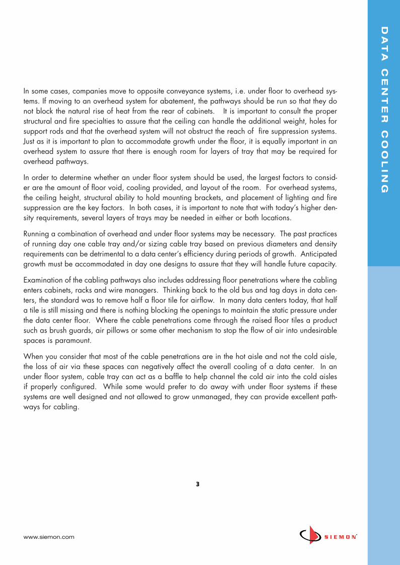
Examination of the cabling pathways also includes addressing floor penetrations where the cablingenters cabinets, racks and wire managers. Thinking back to the old bus and tag days in data cen-ters, the standard was to remove half a floor tile for airflow. In many data centers today, that halfa tile is still missing and there is nothing blocking the openings to maintain the static pressure underthe data center floor. Where the cable penetrations come through the raised floor tiles a productsuch as brush guards, air pillows or some other mechanism to stop the flow of air into undesirablespaces is paramount.
When you consider that most of the cable penetrations are in the hot aisle and not the cold aisle,the loss of air via these spaces can negatively affect the overall cooling of a data center. In anunder floor system, cable tray can act as a baffle to help channel the cold air into the cold aislesif properly configured. While some would prefer to do away with under floor systems if these systems are well designed and not allowed to grow unmanaged, they can provide excellent path-ways for cabling.
3
DA
TA
C
EN
TE
R C
OO
LIN
G
www.siemon.com
WP_DC_Cooling_C_B 8/13/13 1:47 PM Page 3

Cabling pathways inside cabinets are also critical to proper air flow. Older cabinets arenotoriously poor at cable management, in large part because that they were notdesigned to hold the higher concentration of servers that are required today. Older cab-inets were typically designed for 3 or 4 servers per cabinet when cabling and pathwayswere an afterthought. Newer cabinets such as the Siemon VersaPOD™ were designedspecifically for data center cabling and equipment providing enhanced Zero-U patchingand vertical and horizontal cable management assuring that the cabling has a dedicat-ed without impacting equipment airflow. The same can be said for extended depth wiremanagement for racks such as Siemon’s VPC-12.
PODs are changing the face of data centers. According to Carl Claunch of Gartner as quoted inNetwork World…
“A new computing fabric to replace today's blade servers and a "pod" approach to building datacenters are two of the most disruptive technologies that will affect the enterprise data center in thenext few years, Gartner said at its annual data center conference Wednesday. Data centersincreasingly will be built in separate zones or pods, rather than as one monolithic structure, Gartneranalyst Carl Claunch said in a presentation about the Top 10 disruptive technologies affecting thedata center. Those zones or pods will be built in a fashion similar to the modular data centers soldin large shipping containers equipped with their own cooling systems. But data center pods don'thave to be built within actual containers. The distinguishing features are that zones are built withdifferent densities, reducing initial costs, and each pod or zone is self-contained with its own powerfeeds and cooling, Claunch says. Cooling costs are minimized because chillers are closer to heatsources; and there is additional flexibility because a pod can be upgraded or repaired withoutnecessitating downtime in other zones, Claunch said.”
Lastly, a clean data center is a much better performer. Dust accumulation can hold heat in equip-ment, clog air filtration gear, and although not heat related, contribute to highly undesirable stat-ic. There are companies that specialize in data center cleaning. This simple step should be includ-ed yearly and immediately after any cable abatement project.
Inside the cabinets, one essential component that is often overlooked is blanking panels. Blankingpanels should be installed in all cabinets where there is no equipment. Air flow is typicallydesigned to move from front to back. If there are open spaces between equipment the air intakeson equipment can actually pull the heated air from the rear of the cabinet forward. The same canbe said for spaces between cabinets in a row. Hot air can be pulled to the front either horizontal-ly (around cabinets) or vertically (within a cabinet) supplying warmer than intended air to equip-ment which can result in failure. In a recent study of a data center with approximately 150 cabi-nets, an 11 degree temperature drop was realized in the cold aisles simply by installing blankingpanels.
4
DA
TA
C
EN
TE
R C
OO
LIN
G
www.siemon.com
WP_DC_Cooling_C_B 8/13/13 1:47 PM Page 4

Planning for Cooling
Hot aisle, cold aisle arrangements were made popular after the ASHRAE studied cooling issueswithin data centers. ASHRAE Technical Committee 9.9 characterized and standardized the rec-ommendations.(1) This practice is recommended for either passive or active cooling or a combina-tion of the two. The layout in Figure 1 shows four rows of cabinets with the center tiles betweenthe outer rows representing a cold aisle (cold air depicted by the blue arrows). And the rear facesof the cabinets are directed towards the hot aisles (warmed air depicted by the red arrows). In thepast, companies arranged all cabinets facing the same direction to allow an esthetically pleasingshowcase of equipment. Looks, however, can be more than deceiving; they can be completely dis-ruptive to airflow and equipment temperatures.
In a passive cooling system, the data center airflow utilizes either perforated doors or intakes inthe bottom of cabinets for cold air supply to equipment and perforated rear doors to allow the nat-ural rise of heated/discharged air from the rear of the cabinets into the CRAC (Computer RoomAir Conditioner) intake for cooling and reintroduction into the raised floor.
Active cooling systems may be a combination of fans (to force cold air into the faces of cabinetsor pull hot air out of the rear roof of cabinets), supplemental cooling systems such as in row cooling, etc. For the purposes of this paper, only passive cooling systems are addressed as thefactors for active cooling are as varied as the number of solutions. In order to fully understand thecapabilities of each, individual studies and modeling should be performed before any are implemented. ASHRAE recommends pre-implementation CFD (Computational Fluid Dynamics)modeling for the various solutions.
5
Figure 1: Passive cooling,utilizing airflow in theroom and door perfora-tions.
DA
TA
C
EN
TE
R C
OO
LIN
G
www.siemon.com
WP_DC_Cooling_C_B 8/13/13 1:47 PM Page 5

In order to determine the cooling needed, several factors must be known:
- Type of equipment
- Power draw of equipment
- Placement of equipment
- Power density (W/m2 , W/ft2)
- Required computer area (m2, ft2 )
“Computer room floor area totals in the data center would incorporate all of the computing equip-ment, required access for that equipment, egress paths, air-conditioning equipment, and power dis-tribution units (PDU’s). The actual power density is defined as the actual power used by the com-puting equipment divided by the floor area occupied by the equipment plus any supporting space.”[2] This can be defined by the following formula:
Actual power density (W/ft2) = Computer Power Consumption (W) / required computer area (ft2)
White space should not be used in the calculations for actual power density. This figure is impor-tant when planning a data center. 1U servers have significantly different power density require-ments than Blade chassis, storage towers and mainframes. Distribution of this equipment willchange the requirements of the various areas of a data center. For instance if a single zone isselected for Blade servers with a greater power density, passive cooling may not provide adequateair temperatures.
6
Figure 2: One example ofactive cooling utilizingfans to pull hot airthrough the roof
DA
TA
C
EN
TE
R C
OO
LIN
G
www.siemon.com
WP_DC_Cooling_C_B 8/13/13 1:47 PM Page 6

In Table 1. IT Equipment Power consumption, it is obvious that one single solution may not addressall power needs unless the varied densities are in the initial design. Data Centers using primarilylegacy equipment operate at power densities as low as 30W/ft2 (~320 W/m2) as compared tomore modern higher processing equipment which falls closer to the 60-1000W/ft2
(~645 to 1,075 W/m2).
Power consumption can be determined in several ways. Not all will provide an accurate depic-tion of power needs which in turn would not provide an adequate prediction of cooling demand.Past practices utilized the nameplate rating which as defined by IEC 60950[7] clause 1.7 states“Equipment shall be provided with a power rated marking, the purpose of which is to specify asupply of correct voltage and frequency, and of adequate current-carrying capacity.” This ratingis a maximum rating as listed by the manufacturer and very rarely will ever be realized. Utilizingthis rating will cause oversizing of air conditioning systems and cause a waste in both cooling andmoney. Most equipment operates at 65-75% of this listing. The correct number to use is measuredpower consumption. If you will be incorporating new equipment into your data center, equipmentmanufacturers can provide you with this number.
7
Equipment W/ft2 Power Range (~W/m2)3U Legacy Rack Server 525 – 735 (~5,645 – 7,900)4U Legacy Rack Server 430 – 615 (~4,620 – 6,610)1U Present Rack Server 805 – 2,695 (~8,655 – 28,980)2U Present Rack Server 750 – 1,050 (8,065 – 11,290)4U Present Rack Server 1,225 – 1,715 (13,170 – 18,440)3U Blade Chassis 1,400 – 2,000 (15,050 – 21,500)7U Blade Chassis 1,200 – 2,300 (12,900 – 24,730)Mainframe (Large Partitioned Server) 1,100 – 1,700 (11,830 –18,280)
Table 1. IT Equipment Power Consumption2
Intelligent PDUs (iPDUs) can provide actual usage statistics for equipment power draw. By monitoring and trending power variances, data center managers can also determine actualpower and cooling needs as opposed to using theoretical or modeled limits. This also allows better management of loads across the entire floor space.
DA
TA
C
EN
TE
R C
OO
LIN
G
www.siemon.com
WP_DC_Cooling_C_B 8/13/13 1:47 PM Page 7

In addition to the Watts required for equipment, you will also need to determine other sources ofheat to be cooled in the data center. This includes lighting, humans, etc., APC has developed asimple spreadsheet to assist with these equations: (3)
According to APC, cooling capacity is generally about 1.3% of your power load for data centersunder 4,000 square feet. For larger data centers, other factors may need to be taken into accountsuch as walls and roof surfaces exposed to outside air, windows, etc. But in general this will givea good indication of overall cooling needs for an average space.
With that said, this is assuming an overall cooling to floor ratio with a similar load at each cabinet. The question gets asked “What cooling can your cabinet support” The variants are significant. Some variants to consider for cabinet cooling include equipment manufacturer recom-mendations. Many blade manufacturers for instance do not recommend filling cabinets with bladesdue to cooling and power constraints. According to the Uptime Institute, equipment failures in thetop 1/3 of a cabinet is roughly 3x greater than at the lower portion of cabinets. This is due inpart to the natural warming of air as heat rises. In order to increase equipment load in high density areas, some form of supplemental cooling may be required. That does not mean that you
8
Item Data Required Heat OutputCalculation
Heat OutputSubtotal
IT Equipment Total IT Load Power inWatts
Same as Total IT Load Power inWatts
________Watts
UPS with Battery Power System RatedPower in Watts
(0.04 x Power System Rating) +(0.05 x Total IT Load Power)
________Watts
Power Distribution Power System RatedPower in Watts
(0.01 x Power System Rating) +(0.02 x Total IT Load Power)
________Watts
Lighting Floor Area in SquareFeet or Square Meters
2.0 x floor area (sq ft), or 21.53 x floor area (sq m)
________Watts
People Max # of Personnel inData Center
100 x Max # of personnel ________Watts
Total Subtotals from Above Sum of Heat Output Subtotals ________Watts
Table 2. Data Center Heat Source Calculation Worksheet (Courtesy of APC)
DA
TA
C
EN
TE
R C
OO
LIN
G
www.siemon.com
WP_DC_Cooling_C_B 8/13/13 1:47 PM Page 8

need to build in-row cooling into every single row, but rather evaluation for high density areas maymakes sense. The same may be true for SAN areas and other hotter equipment.
Percentage of door perforation will also be a factor. According to the Industrial PerforatorsAssociation, measured air velocity through perforated doors varies with the percentage of perfora-tion. The lower the perforation percentage, the more impact to airflow into the cabinet,as shownin Figure 3.(4) Siemon’s VersaPOD™ doors have 71% O.A peforation allowing maximum air flowfrom cold aisle to hot aisle.
There are supplemental (active) cooling methods that can be added to cabinets to enhance the air-flow either forcing cool air into the cabinets or forcing hot air out. All of these cooling methodolo-gies rely on blanking panels and other steps as outlined earlier in this. There are also workaroundsfor legacy equipment that utilize side discharge heated airflow, such as legacy Cisco® 6509 and6513 switches. While some switch models now use front to rear airflow, other switches such assome of the Cisco Nexus 7000 based switches still use side airflow.
In side air discharge scenarios, equipment should be isolated cabinet to cabinet so that heated airdoes not flow into the adjacent cabinet. Some data centers chose to place this equipment in openracks. The Siemon VersaPOD has internal isolation baffles or side panels to assist with this isolation.
9
0 200 400 600 800 1000 1200 1400 1600 1800 2000 2200 2400
1
2
3
4
5
610% O.A.
0
15% O.A.20% O.A.
26% O.A.
30% O.A.
40% O.A.
50% O.A.
63% O.A.
UNIFORM IMPACT VELOCITY (fpm)
PRESSURE LOSS VS. IMPACT VELOCITY FOR VARIOUS OPEN AREA PERFORATED PLATES Figure 3: Pressure Loss vs Impact
Velocity for Perforated Plates
PRES
SURE
LOS
S (IN
CHES
W.C
.)
DA
TA
C
EN
TE
R C
OO
LIN
G
www.siemon.com
WP_DC_Cooling_C_B 8/13/13 1:47 PM Page 9

Effectiveness of Cooling
Effectiveness of cooling is a necessary test to assure that assumptions made during design are pro-viding the benefits expected. It can also be a good measurement to determine the efficiency ofexisting data centers and provide a roadmap for remediation on a worst case/first solved basis.The “Greeness” of a data center utilizes two metrics:
1. Data Center Infrastructure Efficiency (DCIE) (a reciprocal of PUE below) is a function of total data center power. This does not just mean servers, but rather includes storage, KVM switches, monitors, control PC’s, monitoring stations, etc. Added to the electronics components are all supporting systems such as UPS, PDU’s, switch gear, pumps, cooling systems, lighting and the like. The resulting total divided by Total Facility Power will result in DCIE. This is the preferred method used by IBM®. A DCIE of 44% means that for every 100 dollars spent, 44% is actually used by the data center. Improvements in efficiency can bring this number closer to the 100% ideal number.
2. Power Usage Effectiveness (PUE) is another calculation used by some manufacturers. Simply,DCIE = 1/PUE where PUE = Total Facility Power/IT equipment Power. In both cases, the higher the DCIE percentage, the better the data center is on a green scale.
These numbers will not, however, tell you individually how efficient a particular piece of equipmentis on the same scale. To determine this, you will need to monitor power at the port for each pieceof equipment. New power supplies exist that allow this type of monitoring. When planning formore energy efficient equipment, this can be an invaluable tool.
Another way to measure effectiveness of cooling is to measure cold aisle air temperature through-out the facility. Air is typically measured every other or every third cabinet along the cold aisle. Itis normal to see fluctuations in temperature in the hot aisles due to various equipment heat dis-charge temperatures. But assuring that cool air supply is a consistent temperature will provide youwith a clear indication of how well air circulation and conditioning is working. It will also allowyou to plan where to put hotter equipment if supplemental cooling will not be introduced.
When active cooling is not an option, a data center will see the best consistency in air tempera-tures by spacing the hottest equipment around the data center rather than concentrating it all in asingle “hot spot” area. Planning is a necessary roadmap for today’s hotter equipment. While itmay seem logical to have a blade server area, SAN area, etc. In practice, it may be more effi-cient to have this equipment distributed throughout the data center. It is important to consult yourvarious equipment manufacturers for recommendations.
1 0
DA
TA
C
EN
TE
R C
OO
LIN
G
www.siemon.com
WP_DC_Cooling_C_B 8/13/13 1:47 PM Page 10

Regardless of the design methodologies one chooses to follow for their data center, Siemon hasresources globally to help. For more information on data center best practices, copper and fibercabling systems, or the VersaPOD, please visit www.siemon.com or contact your local Siemon rep-resentative.
References
(1) Thermal Guidelines for Data Processing Environments. Atlanta: ASHRAE, Inc.
(2) Air-Conditioning Design for Data Centers-Accomodating Current Loads and Planning for theFuture; Christopher Kurkjian, PE, Jack Glass, PE, ASHRAE, Inc.
(3) Calculating Total Cooling Requirements for Data Centers, APC, www.apc.com; http://www.apcmedia.com/salestools/NRAN-5TE6HE_R2_EN.pdf
(4) Industrial Perforators Association, http://www.iperf.org/IPRF_DES.pdf
1 1
DA
TA
C
EN
TE
R C
OO
LIN
G
www.siemon.com
WP_DC_Cooling_C_B 8/13/13 1:47 PM Page 11

© 2
013
Sie
mon
WP_
Dat
aCnt
Coo
ling
Re
v. C
8/
13
Visit our website at www.siemon.com fordetailed global office contact information
Worldwide Headquarters North AmericaWatertown, CT USAPhone (1) 860 945 4200 USPhone (1) 888 425 6165
Regional Headquarters EMEAEurope/Middle East/AfricaSurrey, EnglandPhone (44 ) 0 1932 571771
Regional HeadquartersAsia/PacificShanghai, P.R. ChinaPhone (86) 21 5385 0303
Regional HeadquartersLatin AmericaBogota, ColombiaPhone (571) 657 1950
DA
TA
C
EN
TE
R C
OO
LIN
G
WP_DC_Cooling_C_B 8/13/13 1:47 PM Page a.2