Embed Size (px)
Citation preview

ECCC RECOMMENDATIONS - VOLUME 3 Part II [Issue 3]
DATA ACCEPTABILITY CRITERIA AND DATA GENERATION:
CREEP DATA FOR WELDS
ECCC

0509/MC/100 [Issue 3] 11/05/04 Page 2 / 13
blank page

0509/MC/100 [Issue 3] 11/05/04 Page 3 / 13
ECCC RECOMMENDATIONS - VOLUME 3 Part II [Issue 3]
DATA ACCEPTABILITY CRITERIA AND DATA GENERATION: CREEP DATA FOR WELDS
PREPARED BY ECCC-WG1
Mr P Auerkari VTT, Finland (1997- ) Dr D R Barraclough ASTEC, UK (1992-4) Dr-Ing B Buchmayr Technische Univ. Graz, Austria (1992- ) Dr C K Bullough ALSTOM Power (ETC), UK (1992- ) Ir C Coussement Belgium Welding Institute, Belgium (1997-99) Dr-Ing J Granacher IfW TH Darmstadt, Germany (1992- ) Dr S R Holdsworth ALSTOM Power, UK (1992- ) [Convenor] Mr S Holmström VTT, Finland (2000- ) Dr-Ing A Klenk MPA Stuttgart, Germany (1997- ) Dipl-Ing H König ABB ALSTOM Power, Germany (1992-2000) Dr P F Morris CORUS, UK (2000- ) Dr-Ing G Merckling Istituto Scientifico Breda, Italy (1992- ) Dipl-Ing K Niel Siemens KWU, Germany (1992-5) Mr J Orr Corus, UK (1992-99) Mr H Rantala JRC IAM Petten (1997-2001) Dr D G Robertson ETD (formerly ERA), UK (1997- ) [Secretary] Dr-Ing W Rohde VDEh, Germany (1992-96) Prof R Sandström SIMR, Sweden (1992- ) Dr I A Shibli ERA Technology Ltd, UK (1995-6) Dipl-Ing H Theofel MPA Stuttgart, Germany (1992-6) Dr A Vanderschaeghe Stein Industrie, France (1992-4)
EDITED BY: A KLENK and B BUCHMAYR
APPROVED DATE 31/8/05
On behalf of ECCC

0509/MC/100 [Issue 3] 11/05/04 Page 4 / 13
blank page

0509/MC/100 [Issue 3] 11/05/04 Page 5 / 13
ABSTRACT ECCC Recommendations - Volume 3 Part II defines the material pedigree and testing practice information required to accompany (i) existing and (ii) new creep rupture data for welds. The acceptability criteria for existing test results have been set to make full use of the available data. Those defined for new results are the consequence of a comprehensive review of current practices for testing actual welds and simulated HAZ materials (Appendices 1 and 2). ECCC Recommendations Volume 3 Part II user feedback is encouraged and should be sent to: Dr A Klenk [Document Controller] Staatliche Materialpruefungsanstalt (MPA), University of Stuttgart, Pfaffenwaldring 32, D-70569 Stuttgart, Germany. Tel: +49 711 685 3968 Fax: +49 711 685 3053 ECCC may from time to time re-issue this document in response to new developments. The user is advised to consult the Document Controller for confirmation that reference is being made to the latest issue.
This document shall not be published without the written permission of the ECCC Management Committee

0509/MC/100 [Issue 3] 11/05/04 Page 6 / 13
Contents of Volume 3 Part II
1 Overview
2 Weld Description 2.1 Material Pedigree 2.2 Weld Geometry and Sequence, Welding Procedure
3 Creep and Rupture Testing of Welds 3.1 Creep and Rupture Testing of Parent Metal and Weld Metal 3.2 Stress Rupture Testing with Cross Weld Specimen 3.2.1 Testpiece sampling 3.2.2 Shape and size of testpieces 3.2.3 Testing procedure 3.2.4 Test results and assessment of data 3.2.5 Minimum information requirements
4 HAZ Simulation 4.1 Information requirements for HAZ simulated creep samples 4.2 Creep and rupture testing of HAZ simulated specimens 4.3 Determination of weak subzones in the heat affected zone
References Appendix 1
Creep Testing of Weldments: Practices and Investigations on the Effects of Sampling and Size on Creep test results for Weldments
Appendix 2
Characterisation of the creep behaviour of weldments by HAZ simulation.
0509/MC/100 [Issue 3] 11/05/04 Page 7 / 13
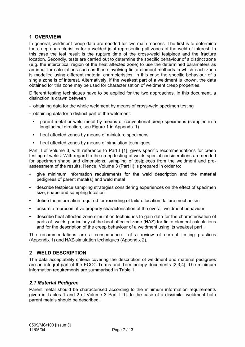
1 OVERVIEW In general, weldment creep data are needed for two main reasons. The first is to determine the creep characteristics for a welded joint representing all zones of the weld of interest. In this case the test result is the rupture time of the cross-weld testpiece and the fracture location. Secondly, tests are carried out to determine the specific behaviour of a distinct zone (e.g. the intercritical region of the heat affected zone) to use the determined parameters as an input for calculations such as those involving finite element methods in which each zone is modelled using different material characteristics. In this case the specific behaviour of a single zone is of interest. Alternatively, if the weakest part of a weldment is known, the data obtained for this zone may be used for characterisation of weldment creep properties.
Different testing techniques have to be applied for the two approaches. In this document, a distinction is drawn between
- obtaining data for the whole weldment by means of cross-weld specimen testing
- obtaining data for a distinct part of the weldment:
• parent metal or weld metal by means of conventional creep specimens (sampled in a longitudinal direction, see Figure 1 in Appendix 1)
• heat affected zones by means of miniature specimens
• heat affected zones by means of simulation techniques
Part II of Volume 3, with reference to Part I [1], gives specific recommendations for creep testing of welds. With regard to the creep testing of welds special considerations are needed for specimen shape and dimensions, sampling of testpieces from the weldment and pre-assessment of the results. Hence, Volume 3 (Part II) is prepared in order to:
• give minimum information requirements for the weld description and the material pedigrees of parent metal(s) and weld metal
• describe testpiece sampling strategies considering experiences on the effect of specimen size, shape and sampling location
• define the information required for recording of failure location, failure mechanism
• ensure a representative property characterisation of the overall weldment behaviour
• describe heat affected zone simulation techniques to gain data for the characterisation of parts of welds particularly of the heat affected zone (HAZ) for finite element calculations and for the description of the creep behaviour of a weldment using its weakest part .
The recommendations are a consequence of a review of current testing practices (Appendix 1) and HAZ-simulation techniques (Appendix 2).
2 WELD DESCRIPTION The data acceptability criteria covering the description of weldment and material pedigrees are an integral part of the ECCC-Terms and Terminology documents [2,3,4]. The minimum information requirements are summarised in Table 1.
2.1 Material Pedigree Parent metal should be characterised according to the minimum information requirements given in Tables 1 and 2 of Volume 3 Part I [1]. In the case of a dissimilar weldment both parent metals should be described.

0509/MC/100 [Issue 3] 11/05/04 Page 8 / 13
2.2 Weld Geometry and Sequence, Welding procedure The minimum information required to describe the weld geometry and welding sequence relating to existing weld creep data, as given in the Terminology document [3] is summarised in Table 1. The mandatory and recommended information required is given in Table 2.
Table 1 Minimum Weld Description Information Required for EXISTING Weld Creep Data
CATEGORY MINIMUM INFORMATION REQUIRED(a)
Material codes and pedigree for parent metal(s)
- see Table 1 of Part I
Weld geometry and sequence
- Joint type(b)
Welding procedure - Welding consumable(c) - Preheat and interpass heating(d) - Intermediate heat treatment (after buttering)(d) - Post weld heat treatment(d)
Weldment characteristics
- Approved for creep testing
Table 2 Minimum Weld Description Information Required for NEW Weld Creep Data
CATEGORY MINIMUM INFORMATION REQUIRED(a)
Material codes and pedigree for parent metal(s)
- see Table 1 of Part I(e)
Weld geometry and sequence
- Joint type(b,e) - Joint preparation(f) - Backing material and type - Total weld thickness
Welding procedure - Welding process details (type, technique, position)(g) - Welding consumable(c,e), deposit analysis(h), flux details(i) - gas details (shielding, backing, plasma)(j) - Preheat and interpass heating(d,e), details - Heat input - Intermediate heat treatment (after buttering)(d,e), details - Post weld heat treatment(d,e), details
Characteristics of the weldment
- Approved for creep testing - Welding qualification standard used - Non-destructive testing (types of examination, imperfection) - Destructive testing (tensile, impact, macro(k))
NOTES: (a) the reporting of additional information is not precluded, see [2] (b) specify reference number according to Table 2.1 of [3] (c) at least one of Alloy name, Specification and Grade name, Trade name shall be supplied to identify the filler metal (d) simple acknowledgement of whether applied (e) mandatory requirements from Table 1 (f) specify the parameters indicated in Table 2.1 of [3] (g) select options from Tables 3.1.1, 3.1.2 & 3.1.3 of [3] (h) at least one of typical or actual to identify the filler metal (i) at least (if appropriate) one of flux classification or flux trade name to identify the flux (j) select options from Table 3.3 of [3] (k) widths of weld zone, HAZ, and (if appropriate) buttered layer(s)
0509/MC/100 [Issue 3] 11/05/04 Page 9 / 13
3 CREEP AND RUPTURE TESTING OF WELDS Creep rupture testing of weldments is much more complex than testing to gain creep and rupture data for a single material. Therefore special considerations should be made. It has to be borne in mind, that the weldment consists of zones with different material behaviour. The different deformation behaviour of these zones may yield stress redistributions or stress enhancement which may cause size and shape dependence of the test result. Therefore before designing a testpiece and the sampling strategy, the aim of the test should be clearly defined. With respect to the aim of test, the influencing parameters discussed in Appendix 1 should be considered.
3.1 Creep and Rupture Testing of Parent metal and Weld Metal Conventional creep tests can be performed on parent material (PM) and weld metal (WM). The recommendations on testing and pre-assessment of data, as well as the minimum information requirements given in [1] are applicable. Testpieces from all weld metal are sampled as longitudinal weld metal specimens (see Figure 1 of Appendix 1), i.e. in the parallel direction with respect to the weld seam. In order to describe the location of these testpieces, in addition to the information given in [1], the depth below the weld surface, k, as given in Figure 1 of [4] is required.
3.2 Stress Rupture Testing with Cross Weld Specimen The gauge length (parallel length) of a cross weld specimen may contain one or two regions of parent metal, part or a complete section of weld metal, and one or two heat affected zones. Usually tests with such testpieces are conducted to obtain time to rupture only. Strain measurement may be recorded in order to obtain useful information for the testing procedure or provide results for comparison when determined using similar testpieces (with regard to geometry and type, number and size of weld zones incorporated).
In general the recommended minimum requirements for future creep rupture testing as given in Table 5b of reference [1] are applicable with the exception of a different minimum gauge length (see 3.2.2).
3.2.1 Testpiece sampling The testpiece should be sampled in a way, that at least one half of the joint is included in the gauge length. This means it contains weld metal and heat affected zones on one side of the joint. In the case of dissimilar welds, heat affected zones may be different. If it is known which side of the joint is the weaker part it is sufficient for the testpiece to contain this side of the joint in the gauge length. Otherwise the whole joint with weld metal and both heat affected zones as well as both parent materials should be included in the gauge length. In special cases a test piece may contain not all zones of a joint. If such tests are carried out, special reporting is required, in particular the metallurgical zones incorporated and the position of these should be reported (see section 3.2 in [4]).
Usually testpieces are sampled with the axes perpendicular to the weld axis (sampling method (a) in Figure 3 of Appendix 1). Another method is to cut the testpiece perpendicular to the fusion line. This is discussed in more detail in Appendix 1.
3.2.2 Shape and size of testpieces Examples for testpieces applicable for crossweld testing are given in Figure 5 and 6 of Appendix 1. Usually testpieces with a smooth cylindrical shape are used. Others may be applied if necessary.
A minimum diameter of 8 mm is necessary to ensure that crossweld specimen deformation behaviour is representative of the welded joint. If the minimum diameter requirement of 8 mm

0509/MC/100 [Issue 3] 11/05/04 Page 10 / 13
cannot be achieved due to limited material thickness and the consequent ratio of fine grained HAZ-width to diameter is large, different necking effects may cause different stress enhancement or stress redistribution and hence influence the rupture time.
A minimum gauge length (parallel length) of at least 5 do ensures that there is no influence on stress rupture time (see Appendix 1).
For rupture testing on similar welds a parallel gauge length of
LC = 5 d0 + Ls'
is recommended (see Figure 4a in Appendix 1).
For a small testpiece diameter or large width of welded zone, exceeding a maximum reference length of 10 d0 should be avoided. In this case, if a symmetrical weld is tested, half of the weld zone should be included in the gauge length (see Figure 4d in Appendix 1).
In order to cater for the possibility of failure in the PM, the testpiece gauge length must contain a considerable length of parent metal. High deformation in the fine grained HAZ may cause stress redistribution in the PM in the direct vicinity of the HAZ. It is therefore recommended that the length of the unaffected PM should not be smaller than 2,5 d0. This can be reached, for example, by having the fusion line at mid-length (see Figure 4c).
For special purposes other specimen types may be used (e.g. waisted specimens, see Figure 5 in Appendix 1).
3.2.3 Testing procedure Uninterrupted or interrupted creep rupture tests can be carried out. The type of test should be noted. The measurement of overall elongation may be advantageous for estimating the rupture time. For large scale specimens the influence of interruptions on the inhomogeneous stress and strain field should be taken into account. From experience it is evident that there is no influence for conventional specimens with diameters up to 12 mm.
3.2.4 Test results and assessment of data Test results are
• Time to rupture at a given stress and temperature
• Fracture location
• Fracture mechanism
Assessed results are
• Rupture Strength of weldment at given temperature and duration
• Strength reduction factor at temperature for duration, t, relative to that of parent metal
• Time reduction factor for given stress and temperature
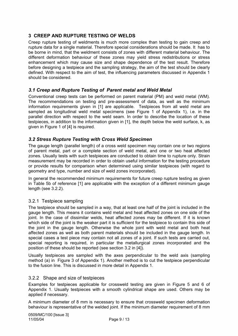
Fracture locations should be given according to the designations in Section 4.2 in [4]. In the literature a classification as given in Figure 6 of Appendix 1 is often used.
Fracture mechanism may be obtained by visual or metallographic examination.
Overall elongation with respect to the reference length may be evaluated according to [1] for the purpose of comparison, if tests with testpieces of same size, shape and partitions of HAZ, weld metal and base metal are carried out.
Additional test results which can be assessed are ductility measures and elongation of distinct zones.

0509/MC/100 [Issue 3] 11/05/04 Page 11 / 13
If elongation and reduction of area after fracture are recorded as test results, it should be noted that these values are only able to provide a qualitative indication which may be used, for example for the comparison of data determined using similar specimens (with regard to size, shape and number and types of weld zones incorporated).
In order to obtain the elongation of various weld zones, it is recommended to place indentations at a regular distance over the gauge length. If in parallel, a metallographic investigation to determine microstructural zones is prepared, the deformation of these zones can be determined by measuring distances between indentations at the beginning and the end of test.
3.2.5 Minimum Information Requirements The minimum information requirements as given in Table 4 of Reference [1] are recommended except those which are not applicable (information on strain and rupture ductilities).
In addition to that, information on testpiece location and sampling (as given in Table 2) should be reported in terms given in Section 3 of reference [3]. The information on test results as summarised in Table 3 should be given in terms of Section 4 of reference [4].
Table 3 Additional Minimum and Recommended Welding Testing Information Requirements(a)
CATEGORY MINIMUM INFORMATION
REQUIRED(a) COMMENTS
Testpiece location
- Depth of testpiece centre line below weld surface
- Weld width at centre line of testpiece
- Orientation of testpiece centre line with respect to axes of weldment(b)
- Weld zones in gauge length
- presence and extent of various
metallurgical zones in testpiece gauge length
Test Results - location - within/at XXHAZ, WM, FL NOTES: (a) the reporting of additional information is not precluded, see [2] (b) mandatory requirement [3]
4 HAZ SIMULATION In order to characterise the creep behaviour of individual zones within the heat affected zone, HAZ simulation procedures are applied to base materials. It is generally intended to apply a temperature-time-history as experienced in a distinct sub-region of the HAZ. This can be either measured by inserted thermocouples or predicted numerically, as described in the German code SEW-088. A detailed description of the creep testing of HAZ simulated structures is given in appendix 2.
There are different methods in industrial use to apply the weld thermal cycle, like
a) induction heating and hold at peak temperature with subsequent cooling in an oil bath
b) heating in a hot salt bath until the peak temperature is reached, immediately followed by cooling in a salt bath at about 100°C and

0509/MC/100 [Issue 3] 11/05/04 Page 12 / 13
c) HAZ simulation using a Gleeble machine
Method c) gives the best agreement with the actual weld thermal cycle and it is more flexible with the capacity for a larger range of heat inputs. The length of constant microstructure is however limited (about 10mm), which has consequences with respect to the gauge length. Methods a) and b) provide a uniform microstructure along the whole specimen length, the heating rate is however much slower and the applicable cooling time is quite restricted.
4.1 Information requirements for HAZ simulated creep samples In addition to the information on the base material (see Tables 1 and 2 of Volume 3 Part I), additional information is required for the applied weld thermal cycle, as shown in Table 4.
Table 4: Additional Minimum Information Required for HAZ Simulation
CATEGORY MINIMUM INFORMATION REQUIRED(a)
COMMENTS
HAZ simulation - Method used (b) - e.g. induction heating and oil cooling, or salt bath heating and cooling, or Gleeble HAZ simulation
Weld thermal cycle
- Peak temperature (b) - Heating rate or heating time to
peak temperature - Holding time at peak temperature - Cooling time between 800 and
500°C (b) - Details of multipass HAZ
simulation (b)
- (second peak temperature and cooling
time, t8/5) Homogeneity of simulated sample
- Length of uniform microstructure
Shape and size of testpieces
- See point 3.2.2 and specify gauge length
Heat treatment - Postweld heat treatment used (yes/no) (b), details
NOTES: (a) the reporting of additional information is not precluded (b) mandatory requirement
4.2 Creep and Rupture Testing of HAZ Simulated Specimens Both creep and creep rupture tests (interrupted and non-interrupted) as well as constant strain rate tests can be used to characterise the creep behaviour of the individual HAZ sub-zones. Especially for Gleeble simulated specimens, it is important to check whether the creep fracture occurred in the homogeneous microstructural length of the sample.
The test results should be reported as specified in Volume 3 Part I.
4.3 Determination of Weak Sub-zones in the Heat Affected Zone One of the main objectives of creep testing simulated HAZ specimens is to find out the weakest sub-region (=“soft zone”). It is therefore recommended to apply a series of different peak temperatures and to draw a plot of hardness or any creep test result as a function of the peak temperature and to compare it with the data of the base material.

0509/MC/100 [Issue 3] 11/05/04 Page 13 / 13
It should be noted, that there might be a small influence in the value of the peak temperature of the soft zone, depending on the type of HAZ simulation. References: [1] ECCC Recommendations Volume 3, 2001, ‘Recommendations for data acceptability
criteria and the generation of creep, creep rupture, stress rupture and stress relaxation data’, Part I ‘Data acceptability criteria and data generation: Generic recommendations for creep, creep rupture, stress rupture and stress relaxation data’, ECCC Document 5224/MC/30 [Issue 5], Edited: J Granacher and S R Holdsworth
[2] ECCC Recommendations Volume 2, 2001, 'Terms and terminology for use with stress rupture, creep and stress relaxation: Testing, data collation and assessment', Part I ‘General terms and terminology and items specific to parent material’, ECCC Document 5524/MC/23 [Issue 7], Edited: P F Morris.
[3] ECCC Recommendations Volume 2, 2001, 'Terms and terminology for use with stress rupture, creep and stress relaxation: Testing, data collation and assessment', Part IIa ‘Terms and terminology for welding processes and weld configurations’, ECCC Document 0509/MC/39 [Issue 2] Edited: C Servetto
[4] ECCC Recommendations Volume 2, 2001, 'Terms and terminology for use with stress rupture, creep and stress relaxation: Testing, data collation and assessment', Part IIb 'Terms and terminology for weld creep testing', ECCC Document 0509/MC/40 [Issue 2], Edited: P F Morris

0509/MC/100 [Issue 3] 11/05/04 Page 14 / 13
APPENDIX 1
CREEP TESTING OF WELDMENTS: PRACTICES AND INVESTIGATIONS ON THE EFFECTS OF SAMPLING AND SIZE ON CREEP TEST RESULTS FOR WELDMENTS
A Klenk [MPA Stuttgart]

0509/MC/100 [Issue 3] 11/05/04 Page 15 / 13
blank page

Appendix 1
Creep Testing of Weldments: Practices and Investigations into the Effects ofSampling and Size on Creep test results for Weldments
A Klenk, MPA Stuttgart
Content
Content .......................................................................................................................................1Abstract.......................................................................................................................................11 Introduction ..............................................................................................................................12 Crossweld specimens ............................................................................................................32.1 Specimen sampling..............................................................................................................32.2 Specimen forms ...................................................................................................................32.3 Designation of crack location (Types of cracking)...............................................................63 Investigations on influencing effects and applicability of uniaxial creep data to
weldments in components...................................................................................................64 Conclusions ..........................................................................................................................10References ...............................................................................................................................11
Abstract
To estimate the life time of components for high temperature application it is important toknow the creep behaviour not only of parent metals, but also of weldments. The aim of thiswork is to provide guidelines which help to determine these data. Investigations areconsidered to obtain creep behaviour for the whole welded joint (e.g. by means of crossweldspecimens) and to determine the specific behaviour of a distinct zone (e.g. heat affectedzone). This requires different testing techniques. Creep testing of weldments needs specialconsiderations as to the specimen shape and dimensions, sampling of testpieces from aweldment, and pre-assessment of results.This Appendix deals with a review of methods and practices for the determination ofweldment creep rupture data with standard specimens. Related to this topic are extensiveinvestigations on the applicability and relevance of laboratory data particularly on thedescription of specimen size and shape effects.
1 Introduction
In general there is a need for creep rupture data for weldments for two different reasons. Thefirst is to characterise the creep behaviour for a welded joint representing all zones of a weld.In this case the test result is the rupture time of the weldment testpiece and the fracturelocation. Secondly, tests are carried out to determine the specific characteristics of a distinctzone (e.g. the intercritical region of the heat affected zone) to use the determined parametersas input for calculations such as those involving finite element methods in which each zone ismodelled using different material characteristics. In this case the specific behaviour of asingle zone is of interest.
The sampling locations are given in Figure 1. The specific behaviour of a part of theweldment can be determined with a specimen machined from a single part. Longitudinalweld metal specimens are used to determine the creep behaviour of the weld metal. Testing

Volume 3 Part II Appendix 1
2
procedures for uniaxial creep testing can be applied for the longitudinal weld metalspecimens [1].
Fig.1 : Locations and specimen sampling in a weld
Cross weld specimens containing all parts of the weldment are used to determine the overallbehaviour of a weld.
Often heat affected zones are the most critical metallurgical regions in welded joints. Sincethese zones are comparatively small one of the following methods must be used todetermine the material characteristics- miniature specimens like disc creep test specimens or impression creep test specimens- specimens machined from simulated material
Miniature specimens are used to determine materialconstants for the part of the heat affected zone theyare machined from. Examples are given in Fig.2 [2].Special testing techniques, e.g. small punch tests [3]are being developed. These techniques are oftenaimed at delivering results for life assessment [4].Investigations on this technique are still under way.A draft code of practise for small punch testing wasdeveloped in [3].
HAZ-simulation techniques and needs are discussedin Appendix 2.
In the following, the scope is focussed on sampling,manufacturing and testing of cross weld specimens,and analyses to ensure the relevance of datadetermined by tests with cross weld specimens.Sampling, shape and size influence the test resultobtained with a cross weld specimen. In thisdocument, experiences mostly based onexperimental data combined with numerical analysesare summarised in order to provide a basis forrecommendations for shape and size of crossweldspecimens and testing procedures. The mostimportant question in this context is whether thestress redistribution in a specimen during creep issimilar to that in a component.
Figure 2: Miniature specimensafter Hyde et.al [2]
Impression creep test specimens
Disc creep test specimen

Volume 3 Part II Appendix 1
3
This means that the influencing effects on the behaviour of a weld in a component should beconsidered with regard to representation by a testpiece. These effects are- Differences in strength between base and weld material- Different microstructures in the HAZ- Development of zones near the fusion line with change in chemical composition due to
diffusion- Additional thermal stresses due to different dilatation coefficients- Stress enhancement due to different creep rates in constituent materials- Residual stresses due to the welding and manufacturing process.
In particular the last three effects can be quite different in a testpiece.
2 Crossweld specimens
2.1 Specimen sampling
In principle, the testpiece can bemachined from a weld perpendicular tothe symmetry line of the weld (a), orperpendicular to the fusion line (b),Figure 3.
Figure 3: Sampling of cross weld specimens (after [2])
Sampling technique (a) is most common and sampling is comparatively easy. However, thissampling technique raises the following problems:- The specimen is not symmetrical.- Weld metal zone and heat affected zone (HAZ) have different relative lengths to the
gauge length.- The differences in material behaviour, in particular different steady state creep rates
cause stress enhancement in the specimen which may be different from that in acomponent.
- It is likely that there are cross-sections in the specimen consisting of different materialtypes (e.g. fine grained + coarse grained heat affected zone material or weld metal +coarse grained heat affected zone). This exacerbates any problems associated withdifferential creep rates.
Obviously while sampling technique (b) is able to avoid some of these problems, machiningis much more complex. For distinct geometries it is not possible to sample the testpiece inthis way.
Dependent on the size of welded parts and the specimen size, in particular for sampletechnique (a), the following configurations may be employed:- The specimen contains all zones of a weld (weld metal, heat affected zones and base
metal. For similar welds it is usually assumed that the weld is symmetrical with respect tothe centre-line in the weld metal. For dissimilar welds there are two base metals and twodifferent heat affected zones.
- The specimen contains only parts of the weld.Dependent on these, different stress distributions and creep behaviour will be experienced.
2.2 Specimen formsExamples for specimens are given in Figures 4 and 5. Beside different sampling techniquesthe following differences in specimen form can be found.
ab

Volume 3 Part II Appendix 1
4
a) Smooth specimen for stress rupture tests
b) Smooth specimen for stress or creep rupture test (German Arbeitsgemeinschaft Warmfeste Stähleund Hochtemperaturwerkstoffe and IfW Darmstadt)
c) Smooth specimen with a fusion line exactly mid-length [7,9]
d) Smooth specimen containing only one side of symmetrical weld [7,9]
Figure 4: Cross weld specimens used in several investigations
Lc= 5 d0 + Ls'
do

Volume 3 Part II Appendix 1
5
Figure 5: Cross weld specimen types (after [2])

Volume 3 Part II Appendix 1
6
- Different gauge length to diameter ratios- Different absolute diameters- Different constituent material volume ratios (HAZ/weld metal/base metal)- Locations of heat affected zone and weld metal zone in the gauge length.
Unfortunately in publications there are often no details on specimen forms. However, theprincipal forms given in Figure 4 are most common. A gauge length to diameter ratio ofapproximately 10 as given in Figure 4 b) was found for example in [5] a gauge length todiameter ratio of approximately 5 was found for example in [6,7,8] for investigations onsimilar and dissimilar welds.
2.3 Designation of crack location (Types of cracking)The designations for the characterisation of crack locations are illustrated in Figure 6.According to [10] and [11] the classification of cracks depending on location and orientationof a crack is given as Type I if the crack location is in the weld metal, Type II if the crackstarts at the fusion line, Type III if the crack locates in the coarse grained HAZ (CGHAZ) andType IV if the crack is in the fine grained HAZ (FGHAZ) or the intercritical zone (ICHAZ).
Figure 6: Classification of crack locations
3 Investigations on influencing effects and applicability of uniaxial creepdata to weldments in components
The sampling technique has to ensure the applicability of creep data to components.Therefore numerous experimental and numerical investigations have been carried out inorder to characterize the effects of size and sampling. Results of large scale tests have beencompared to laboratory data. Both investigations have been supported by numericalanalyses.
The effect of size and shape on creep test results was discussed in detail in [12]. For a smalldiameter to gauge length ratio a significant dependence on specimen diameter was found onrupture life, Figure 7. However, if a reasonable gauge length is used this effect is negligible.
Figure 7: Variations in rupture life with specimen dimensions [12]
IIIIVFi
I IIWeldmetal
Heat affectedzones

Volume 3 Part II Appendix 1
7
The effect of different specimen diameter on elongation and strain, however, was found to besignificant, Figure 8 for constant load tests for a CrMoV steel. In this case different rupture
Figure 8: Variation of strain time behaviour with specimen diameter [12]
lives were determined. For stress controlled test the effect was smaller. The differencebetween stress and load controlled test on rupture lives is larger than the influence ofdiameter. A comparison of rectangular and cylindrical shape was made, Figure 9. Underconditions of a similar area no significant effect of shape has been found.
A summary of cross weld creep data for CrMo, CrMoV and 9 to 12% Cr steels is tabled. Atendency to Type IV cracking for increasing diameter was observed. In general the tendencyof increasing rupture life with increasing diameter was confirmed. For P91 material asignificant increase of rupture life with increasing cross section area is shown.
Figure 9: Effect of specimen shape
Parker recommends for the parallel length to add the length of the weld to the normal gaugelength of 5 times diameter. This is in accordance to BS 709. An increasing rupture life withincreasing cross sectional area of specimen resp. diameter is also found in all otherinvestigations. For an electron beam weldment investigated with standard creep specimens(l=5d), an underestimation of creep strength compared to full thickness specimens wasfound. A factor of 1.5 to 3 in rupture time was found.
Detailed analyses using a finite element method have been carried out by Storesund and Tu[12]. As a constitutive equation Norton´s law was used applying different constants for eachof the four constituents of the weld: parent metal fine grained HAZ, coarse grained HAZ andweld metal. It was found that there is a significant life enhancement with increasing diameter.The location of the maximum stress enhancement in the specimen can also be altered whenthe diameter is changed. The change of the HAZ width has certain influence on the creep life

Volume 3 Part II Appendix 1
8
of the specimen whereas the change of weld metal width does not show such influence in apractical range. No influence of changing the angle of weld could be seen. This is confirmedin [14] and in agreement with investigations on circumferential welds in pipes [15], Figure 10.
a) b)
Figure 10: Stresses in HAZ (a) and weld metal zone (b) for different weld angles [15].
In order to provide a method to analyse laboratory data and component data in a similar wayand thus make the lab data applicable to components Hyde, Tang and Sun [2] used ananalytical method with a reference stress based on limit load solution for determination ofstress enhancement in the weld zones. Comparison to finite element calculations showed,that with the analytical method only approximate solutions could be obtained.
Experimental tests with large scale specimens, Figure 11, have been carried out [7] andhave been analysed by finite element method, Figure 12, for 12%Cr steel welds anddissimilar welds 12%Cr/1%Cr.
For the similar welds, a migration of the rupture location from base metal into the fine-grainedHAZ was observed with decreasing nominal stress. It could be stated, that the creep rupturestrength of the welded joint was beyond that of the weakest HAZ microstructure (simulatedspecimens). For dissimilar welds, the large-scale specimens exhibited longer creep rupturetimes than the laboratory specimens, Figure 13. Results of the finite element calculationsshowed that in large-scale specimens the stress- and strain redistribution due to creep isslower than in small scale specimen which is caused by a higher constraint in large-scalespecimens, Figure 14.

Volume 3 Part II Appendix 1
9
Fig.11 Large scale specimens Fig. 12: Finite element model.
Figure 13: Influence of specimen size on creep rupture time of dissimilar welds [7]

Volume 3 Part II Appendix 1
10
Figure 14: Axial stress distribution in large scale specimen at specimen centre and nearouter surface
4 Concluding remarks
The needs and difficulties in weld creep testing are discussed. Currently used specimenforms are given. Investigations on the influence of specimen shape and size have beenreviewed. There is a tendency for increasing rupture life with increasing diameterrespectively cross sectional area. The size of heat affected zone influences creep test resultsas well as the partitions of the different weld zones in the parallel length of the sampledspecimens. Detailed numerical and experimental analyses with large scale testpieces showthat large geometries normally have longer rupture lives and a slower redistribution ofstresses. Based on these findings the recommendations given in the main part of thisdocument have been derived.

Volume 3 Part II Appendix 1
11
References
[1] ECCC Recommendations Volume 3, 2001, ‘Recommendations for data acceptabilitycriteria and the generation of creep, creep rupture, stress rupture and stress relaxationdata’, Part I ‘Data acceptability criteria and data generation: Generic recommendationsfor creep, creep rupture, stress rupture and stress relaxation data’, ECCC Document5224/MC/30 [Issue 5], Edited: J Granacher and S R Holdsworth.
[2] T.H. Hyde, A. Tang and W. Sun:Analytical and computational stress analysis of welded components under creepconditions, International Conference on Integrity of High Temperature Welds,Nottingham, Nov 1998
[3] Small Punch Test Method Assessment for the Determination of the Residual Creep Lifeof Service Exposed Components ("Small Punch"), CEC - COPERNICUS - project ERB-CIPA-CT94 0103, Final Report, January 1998
[4] J.D. Parker, G.C. Stratford, N. Shaw and H: Metcalfe: The Application of Minature DiscTesting for the Assessment of Creep Damage in CrMoV Rotor Steel
[5] R. Wu, J. Storesund, R. Sandström and E. von Walden: Creep properties of 1Cr0.5Mosteel welded joints with controlled microstructures. Welding in the world Vol. 30, No11/12, pp. 329-336, 1992
[6] F. Brühl, H. Cerjak, H. Müsch, K. Niederhoff und M. Zschau: Verhalten des 9%Chromstahles X10 CrMoVNb 9 1 (Teil 2: Schweißverbindungen), VGB-Kraftwerkstechnik 69, Heft 12 (Dezember 1989)
[7] K.Kussmaul, K. Maile and W. Eckert: Influence of Stress State and Specimen Size onCreep Rupture of Similar and Dissimilar Welds, ASTM STP 1171, 1993, pp. 341-359
[8] Theofel,H. und K. Maile: Einfluß der Wärmeeinbringung beim Schweißen auf dieZeitstandfestigkeit und das Kriechverhalten von Schweißverbindungen, untersucht anwarmfesten CrMoV-Stählen mit 1% und 12% Chrom, Schlußbericht zumForschungsvorhaben AIF Nr. 5710, MPA Stuttgart, 1986
[9] K. Maile, H. Theofel, W. Bendick und M. Zschau: Zeitstandverhalten von P91-Schweißverbindungen, Stahl und Eisen 117 (1997), pp. 101-105
[10] H.J. Schuller, L. Hagn and A. Woitscheck: Cracking in the Weld Region of ShapedComponents in Hot Steam Pipelines - Materials Investigations, Der Maschinenschaden47, pp. 1-13
[11] S.J. Brett: Cracking Experience in Steam Pipework Welds in National Power, VGBConference "Materials and Welding Technology in Power Plants 1994", Essen, 15-16March 1994
[12] J.D. Parker: The effect of Specimen Size on Creep Behaviour, Welding in the World,Vol 37 (1996) No.5, pp. 233-241
[13] J. Storesund and S.-T. Tu: Geometrical effect on creep in cross weld specimens. Int. J.Pres.Ves. &Piping Vol. 62, (1995) pp. 179-193
[14] B. van der Schaaf: Creep and Tensile Properties of Four types of 316-Weldments, Lifeof Welds at High Temperatures, 12.-13.6.1990, ImechE, London
[15] M. Law and W. Payten: Weld Performance under creep using finite element modelling,Int.J.Pres.Ves&Piping 72 (1997) pp 45-49

Volume 3 Part II Appendix 1
12
blank page

0509/MC/100 [Issue 3] 11/05/04 Page 16 / 13
APPENDIX 2
CHARACTERISATION OF THE CREEP BEHAVIOUR OF WELDMENTS BY HAZ-SIMULATION
B Buchmayr [TU Graz]

0509/MC/100 [Issue 3] 11/05/04 Page 17 / 13
blank page

Volume 3 Part II Appendix 2
1
Appendix 2
Characterisation of the creep behaviour of weldments by HAZ-Simulation
Bruno Buchmayr, TU Graz, Dept. Materials Science, Welding and Forming
CONTENT
Abstract1. Introduction2. Principles of HAZ simulation3. Determination of the weld thermal cycle4. HAZ Simulation Procedures4.1 Gleeble welding simulation4.2 Induction heating and oil quenching4.3 Salt bath heating and quenching4.4 Comparison of the HAZ simulation techniques5. Comparison between the behaviour of real weldments and HAZ simulated structures5.1 Creep behaviour of 1CrMoV HAZ structures5.2 Gleeble testing of advanced 9-12%chromium steels6. HAZ simulation to generate constitutive creep equations for FEM calculations7. Conclusions8. References9. Literature on the creep behaviour of HAZ simulated samples
Abstract
The behaviour of weldments under creep loading is mainly tested using cylindrical specimenstaken from cross welded weldments. As an alternative, creep testing of HAZ-simulated structuresis also done in order to characterise the individual subzones within the heat affected zone. Themain advantage of this procedure is, that gradual changes in the creep behaviour of the heataffected zone or even soft zones can be determined. Compared to miniature samples, a largervolume is produced, which ensures a lower scatter of the test results. In this report, various HAZsimulation techniques are described and compared, but the main focus will be on Gleeble testing.Details of creep testing of HAZ simulated specimen are shown. The additional gained informationis discussed with special emphasis on the comparability with the behaviour of real weldments.The advantages and disadvantages of creep testing of HAZ simulated structures are consideredand critically assessed. Creep data on HAZ simulated specimens of 1CrMoV and 9-12%chromium steels are shown as an example. The necessity of such data for FEM calculations isalso emphasised.

Volume 3 Part II Appendix 2
2
1. Introduction
The quantification of the creep behaviour of weldments is much more challenging compared tothe base material, because of the heterogeneity of the microstructure in the weld metal, in theheat affected zone and the adjacent base material in a rather narrow range. Typically, creepsamples are taken from cross welded specimens, where the gauge length includes the weldmetal as well as the HAZ and some base metal on both sides of the weld. The determination ofany meaningful measurement of the elongation is quite doubtful. In addition to the conventionaltesting of weldments, creep testing of weld simulated structures is performed in order tocharacterise the creep behaviour in the distinct sub-regions of the heat affected zone. Thereby,the weld thermal cycle in various sub-zones of a weldment is transferred to a specimen, so thatthe testing volume is significantly enlarged, which should reduce the influence of surroundingzones and therefore the scatter. In this report the general procedure of HAZ simulation and creeptesting of HAZ-simulated samples is documented, including some remarks on the beneficial andcrucial aspects of this kind of testing. By comparison of the creep rupture behaviour of HAZsimulated structures with cross samples taken from weldments, the possibilities for datatransfers are considered. Furthermore, the available information in the open literature is referredto. Some case studies of some heat resistant steel grades (1CrMoV, P91, P92) are considered indetail. Finally, the use of creep data on HAZ simulated specimens for finite element calculation ofthe creep behaviour of real components as in power plants is discussed.
2. Principles of HAZ simulation
The mechanical properties including also the creep properties of a weldment depend on manifoldinfluencing parameters, which have to be taken into account. Figure 1 shows a simplified matrixof various weldability aspects, their interactions and influencing parameters.
Figure 1: Influencing factors and characteristic parameters regarding the weldability of steels.

Volume 3 Part II Appendix 2
3
As illustrated, there are a variety of influencing and interacting parameters, which are not easy tokeep in mind during an assessment, therefore previous attempts have been focussed to combinesingle influencing factors to so-called „characteristic parameters“ for a particular aspect. Most ofthese parametric equations are based on multiple regression analysis of large experimental datasets.
The basic idea of HAZ simulation is to take into account the most important parameters, whereasdisturbing parameters are eliminated as far as possible. In order to investigate the influence of themost important welding parameters on the resulting mechanical properties, the principle route, asshown in figure 2, is applied. There is a direct correlation between the mechanical properties andthe HAZ microstructure, which depends on the cooling rate and the material dependenttransformation kinetics, which itself is influenced by the austenite grain size. The austenite grainsize is given by the peak temperature or by the distance from the fusion line, respectively. Theweld thermal cycle is simply characterised by the cooling time t8/5 between 800 and 500°C andthe peak temperature. The cooling time t8/5 depends on the plate thickness, the welding process(thermal efficiency), the joint type, the welding parameters (current, voltage, travel speed, or heatinput) and the preheating temperature.
Chemicalcomposition
Plate thickness
Welding process
Joint type
Welding parameters
Preheating, IP-Temp.
Coolingtime t 8/5
Mechanical properties
HAZ Microstructure
Transformationkinetics
Distance from FL -> Tpeak
Austenitegrain size
Figure 2: Coupling of the most influencing factors on the HAZ properties in a logical way

Volume 3 Part II Appendix 2
4
3. Determination of the weld thermal cycle
There are many means to calculate the weld thermal cycle, as summarised in figure 3.
1. Analytical Solution (Rosenthal , Rykalin )
2. Analytical Solution for modified heat sources
3. Cooling time concept t8/5 (SEW088)
4. Finite difference method
5. Finite element method (2D, 3D)
)4/exp(2
/ atrt
vETT
o−⋅
⋅⋅⋅⋅=−
ρλπ
35/8800
1500
12
FTT
Etoo
⋅
−
−−
⋅⋅⋅
⋅=λπ
η
[ ] [ ] { }
=⋅+
⋅
••
QTKTC
),,( 1,,1,,1 +−+ = jijijiji TTTfT
Figure 3: Approaches mainly used for the calculation of the weld thermal cycle
The most-widely used procedure to predict the weld thermal cycle is the standardised coolingtime concept according to the German standard SEW088, which is based on the analyticalsolution derived by Rosenthal. There are two principle cases, firstly, when the heat flow is two-dimensional (thin sheet) and secondly, when it is three-dimensional (thick plate). Therefore thefirst step is to calculate the transition plate thickness for two or three-dimensional heat flow.Further details are given in SEW088. At TU Graz, the author developed a computerised softwarepackage to perform the prediction of the weld thermal cycle. The computer package is called“HAZ-calculator” [1], which is available via DVS Düsseldorf. The main menu of this software isshown in figure 4. The thermal cycle is calculated using routine 4, base on the SEW-approach.The input parameters and the final result is shown in figure 5 and 6.
Figure 4: Main Menu of software “HAZ-Calculator”, developed at TU Graz

Volume 3 Part II Appendix 2
5
Figure 5: Calculation routine 4 “Weld thermal cycle” in the software HAZ-Calculator
Figure 6: Calculated weld thermal cycles for one cooling time t 8/5 and three peak temperatures
By definition one can predict the cooling time t8/5 from various sets of information, like fromarc voltage, welding current and welding speed, preheating temperature and plate thickness,heat input, preheating temperature and plate thickness,electrode diameter and runout ratio andelectrode diameter and fused area.
For the graphic presentation of the whole thermal cycle, the user has to define the peaktemperatures or the distance from the fusion line.
Volume 3 Part II Appendix 2
6
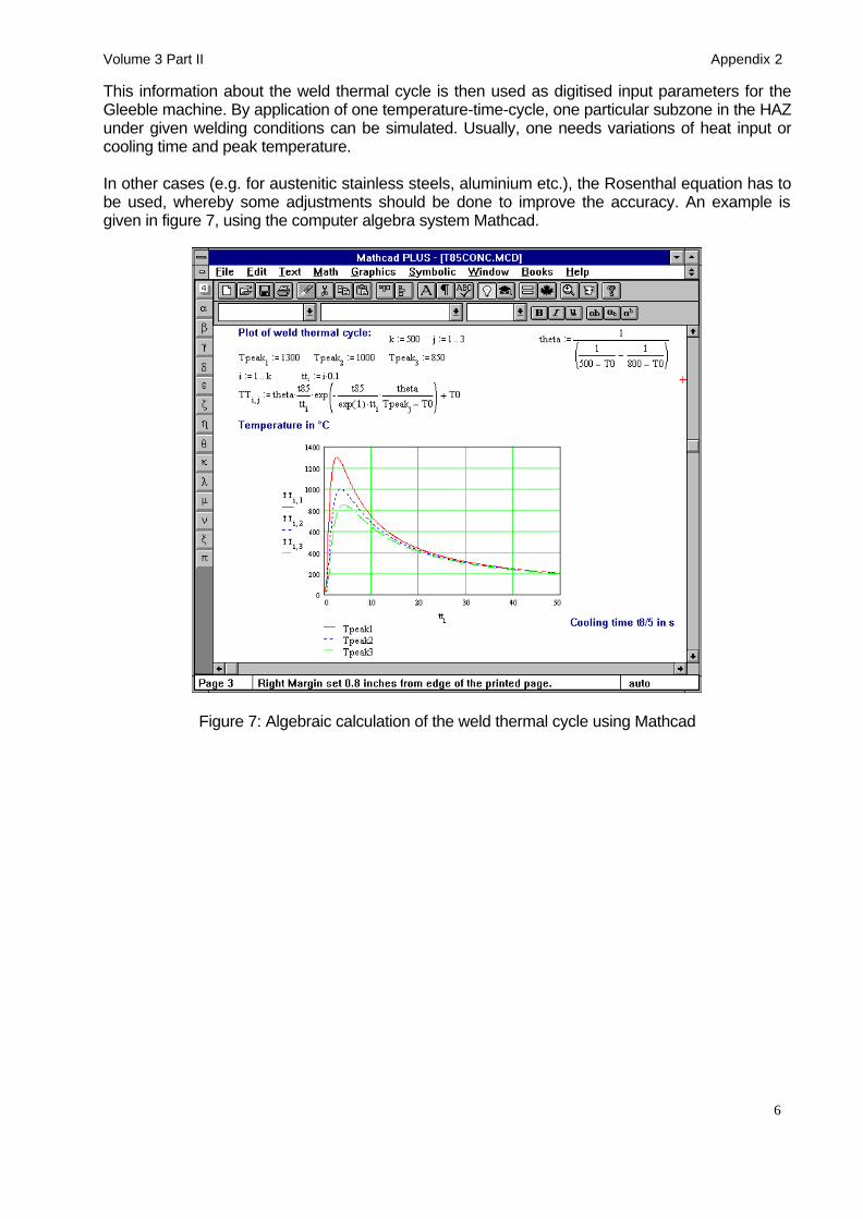
This information about the weld thermal cycle is then used as digitised input parameters for theGleeble machine. By application of one temperature-time-cycle, one particular subzone in the HAZunder given welding conditions can be simulated. Usually, one needs variations of heat input orcooling time and peak temperature.
In other cases (e.g. for austenitic stainless steels, aluminium etc.), the Rosenthal equation has tobe used, whereby some adjustments should be done to improve the accuracy. An example isgiven in figure 7, using the computer algebra system Mathcad.
Figure 7: Algebraic calculation of the weld thermal cycle using Mathcad

Volume 3 Part II Appendix 2
7
4. HAZ simulation procedures
There are different methods in industrial use to apply the weld thermal cycle, like- Gleeble HAZ simulation,- induction heating and cooling in an oil bath and- heating in a hot salt bath and cooling in a moderate tempered salt bath.The main objective of all these techniques is to apply the weld thermal cycle as measurable in adistinct subregion of the HAZ to a sample with larger testing volume. In the following thesemethods are described.
4.1 GLEEBLE welding simulation
Gleeble simulation is a very useful tool for the determination of the microstructure in the heataffected zone. By the controlled application of thermal and/or thermomechanical cycles accordingto a particular weldment geometry and the welding parameters, nearly every position in theweldment can be produced representatively and the microstructure can be investigated usingconventional or sophisticated skilful techniques.The Gleeble system is a fully interfaced system, readily programmed to provide reference signalsfor closed loop control of both thermal and mechanical operations. Heating is accomplished by theflow of low-frequency alternating current in the specimen with heating rates up to 10000 K/s. Thefeedback signal necessary for closed-loop control is normally obtained from a fine wirethermocouple percussion welded to the specimen surface.In order to determine a specific (creep) property of a particular region in the HAZ, the weld thermalcycle (determined as described in chapter 3) is fed in the control computer and a cylindricalsamples is heated up very rapidly to the desired peak temperature by direct current flow with up to6000A. The cooling is provided by the heat flow through the copper jaws. At slow cooling rates, thegiven T-t-curve is very well controlled, faster cooling rates can be reached by reducing the freespan between the jaws or by external gas cooling. Figure 8 shows the weld thermal cycles whichwere applied for weldability tests of 9-12% Cr-steels regarding the likelihood of „type IV“-cracking.
Time, s50
0
200
400
600
800
1000
1200
1400
0 5 10 15 20 25 30 35 40 45
SETot8/5d
====
25,2 kJ/cm225 °C21,6 s30,0 mm
Pea
k T
empe
ratu
re,
°C
Figure 8: Weld thermal cycles for the coarse-grained zone and in the vicinity of theintercritical zone for given welding parameters.

Volume 3 Part II Appendix 2
8
The resulting microstructure in the middle of the test specimen, where the thermocouple islocated, is then exactly the same as in a real weldment at the considered position.
The advantages of Gleeble weldability testing can be summarised as follows:- accurate application and measurement of the thermal cycle for a predefined location in the HAZ- after simulation, an enlarged volume for further metallographic investigations or mechanical
tests is available compared to the limited size in a real weldment- due to the larger volume and higher homogeneity of the simulated microstructures, there is a
reduced scatter of the HAZ properties- phase transformations during welding can be measured by thermal analysis or dilatometric
measurement of the C-strain- in addition, mechanical stresses during the cooling phase can be superimposed in order to
simulate any contraction of the surrounding material- The mechanical material properties during cooling from high temperatures can be directly
measured for input in finite element calculations.- Other combined thermomechanical tests can be applied, like reheating relaxation test, hot
ductility test, partly-melting and afterwards cooling to simulated the behaviour of the weld metal.
Some pitfalls are however:- The temperature profile in longitudinal direction causes some experimental troubles.- Effects of local gradients in microstructure, properties and residual stresses are not taken into
account when using the HAZ simulation technique.A quite common procedure for weldability Gleeble testing is illustrated in figure 9.
Typical sample geometry for Gleeble testingDue to the high electric power available (max. current is about 6000A), specimens up to 16mmcan be used. At TU Graz, typically round specimens with a diameter of 10mm is used for HAZsimulation. The typical length is about 140mm. Depending on the further testing procedures, thereare also other geometries possible (also rectangular geometries). For any thermo-mechanicalsimulation, the specimen is fixed by a thread of about M10, M12 or M14.
The most important aspect is related with the temperature profile along the Gleeble specimen.Due to heat flow into the jaws there is a considerable temperature profile. The situation can onlybe changed by using less conducting jaw material and longer free span.
Usually, there is only a range of up to 10mm in the middle, where the temperature is almostconstant. That means, that for any further evaluation and further testing (like creep rupturetesting), the simulated specimen has to be turned in the middle, to reduce the nominal diameterand to favour that the specimen will brake at a position where the conditions are well controlled.This also means, that a limited gauge length (10mm) has to be used, compared to otherstandardised specimens.

Volume 3 Part II Appendix 2
9
Principle of HAZ-simulation using aGleeble device
Principle of HAZ-simulation using aGleeble device
GLEEBLE Simulation of- impact toughness samples (10x10 mm)- cylindrical specimens (∅ 12 mm)
GLEEBLE Simulation of- impact toughness samples (10x10 mm)- cylindrical specimens (∅ 12 mm)
EtchingEtching
Post Weld Heat TreatmentPost Weld Heat TreatmentPost Weld Heat Treatment
annealing procedure
0
200
400
600
800
0 1 2 3 4 5 6
time [h]
Tem
per
atu
re [°
C]
Weld Thermal Cycles
0
200
400
600
800
1000
1200
1400
0 20 40 60 80 100
time [s]
Tem
per
atu
re [°
C]
Determination of weld thermalcycles to be applied (Tp, t8/5)
(using HAZ-CALCULATOR, GLEEBLE-Programming)
Determination of weld thermalcycles to be applied (Tp, t8/5)
(using HAZ-CALCULATOR, GLEEBLE-Programming)
Metallography(Light-microscopy, REM, TEM)
Metallography(Light-microscopy, REM, TEM)
Hardnesstesting HV 10
Hardnesstesting HV 10
Toughness behaviour(transition temperature)
Toughness behaviour(transition temperature)
impact toughness curve
0
50
100
150
200
250
-200 -100 0 100 200
Temperature [°C]
imp
act e
ner
gy
[J]
ther
mo
-mec
han
ical
test
s(c
reep
, fat
igu
e, c
orr
oss
ion
)
ther
mo
-mec
han
ical
test
s(c
reep
, fat
igu
e, c
orr
oss
ion
)
Figure 9: Typical procedure for GLEEBLE weldability testing and subsequent propertydeterminations.
Volume 3 Part II Appendix 2
10
4.2 Induction heating and oil quenching
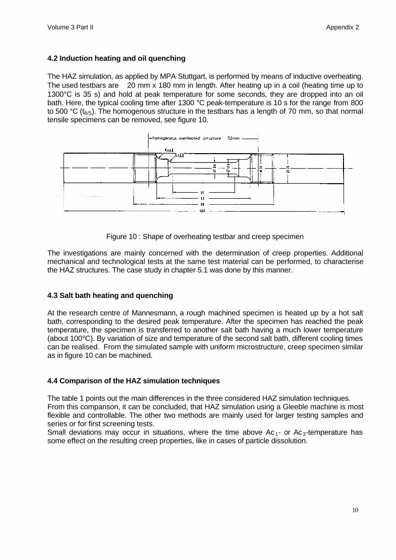
The HAZ simulation, as applied by MPA Stuttgart, is performed by means of inductive overheating.The used testbars are ∅20 mm x 180 mm in length. After heating up in a coil (heating time up to1300°C is 35 s) and hold at peak temperature for some seconds, they are dropped into an oilbath. Here, the typical cooling time after 1300 °C peak-temperature is 10 s for the range from 800to 500 °C (t8/5). The homogenous structure in the testbars has a length of 70 mm, so that normaltensile specimens can be removed, see figure 10.
Figure 10 : Shape of overheating testbar and creep specimen
The investigations are mainly concerned with the determination of creep properties. Additionalmechanical and technological tests at the same test material can be performed, to characterisethe HAZ structures. The case study in chapter 5.1 was done by this manner.
4.3 Salt bath heating and quenching
At the research centre of Mannesmann, a rough machined specimen is heated up by a hot saltbath, corresponding to the desired peak temperature. After the specimen has reached the peaktemperature, the specimen is transferred to another salt bath having a much lower temperature(about 100°C). By variation of size and temperature of the second salt bath, different cooling timescan be realised. From the simulated sample with uniform microstructure, creep specimen similaras in figure 10 can be machined.
4.4 Comparison of the HAZ simulation techniques
The table 1 points out the main differences in the three considered HAZ simulation techniques.From this comparison, it can be concluded, that HAZ simulation using a Gleeble machine is mostflexible and controllable. The other two methods are mainly used for larger testing samples andseries or for first screening tests.Small deviations may occur in situations, where the time above Ac 1- or Ac3-temperature hassome effect on the resulting creep properties, like in cases of particle dissolution.

Volume 3 Part II Appendix 2
11
Feature Gleeble simulation Induction heating + oil quenching
Salt bath heating +salt bath cooling
heating rate high, as in HAZ slower as in HAZ slower as in HAZpeak temperature exact programmable exact controllable exact when using TCholding time atpeak temperature
rounded T-t-curve asnumerically predicted
some seconds none
cooling rate programmable given by oiltemperature andsample size
determined by salt bathtemperature and samplesize
homogeneity ofmicrostructure
only in a short length ofabout 10mm
over the whole lengthconstant structure
over the whole lengthconstant structure
gauge length reduced as for base material as for base materialreproducibility high moderate moderateagreement withdistinct HAZstructure
excellent good good
consideration ofconstraint effects
possible by applying ofmechanical loading
not done impossible
additional datameasurable
dilation measurement none none
simulation costsand duration
high low low
Table 1: Comparison of different HAZ simulation techniques
5. Comparison between the behaviour of real weldments and HAZ simulatedstructures
5.1 Creep behaviour of 1CrMoV HAZ structures
As a case study, investigations on 1CrMoV (cast) steel [2] are described. The creep tests ofHAZ simulated samples with different peak temperatures were carried out at 550 °C. In figure 11the rupture-elongation values are plotted versus rupture time for all structures, while figure 12shows the creep rupture curves, together with the scatter band for base material 1CrMoV forcomparison reasons. The coarse grained microstructure 1300/S shows the worst (< 2 %) ruptureelongation, but has the highest creep strength. The fracture curves of refined microstructures(840/S and 900/S) lie below the scatter band, their rupture elongations show the highest values (>30 %).

Volume 3 Part II Appendix 2
12
Figure 11: Rupture elongation behaviour of a 1CrMoV cast steel
Figure 12: Comparison of creep rupture strength for different microstructures
In figure 13 for various HAZ-structures, having different peak temperatures, the rupture strength forspecific times are compared with the lower BM-scatter band values for the same times to failure.For peak temperatures from 800 to nearly 1100 °C the isochrones are lower than the scatter bandvalue. Figure 14 shows the minimum creep rate over the stress for the various structures. Thisleads to results in a broad scatter band with higher creep rates at the fine grained microstructuresand lower creep rates at the coarse grained microstructures, the base material is situated inbetween. The influence of the different peak temperatures on the creep rate is shown in figure 15.Regarding the band of curves with equivalent stress, the reason for the lowest creep strength offine grained microstructures (Tp ≤ 900 °C) becomes obvious.

Volume 3 Part II Appendix 2
13
Figure 13: Influence of peak temperature on creep rupture strength of 1CrMoV steel
Figure 14:Influence of peak temperature on minimum creep rate
The results show, that the fine grained microstructures have the lowest creep strength, which liesconsiderably below the one of base material. The coarse grained microstructures show highercreep strength up to the investigated medium rupture time, however the deformation capability isdrastically reduced. In the real weld, the particular areas of the HAZ are connected with oneanother. Due to stress redistribution and multiaxial stress state, the creep deformation capabilityin the various areas of HAZ may be influenced. A low ductility rupture may occur.
Volume 3 Part II Appendix 2
14
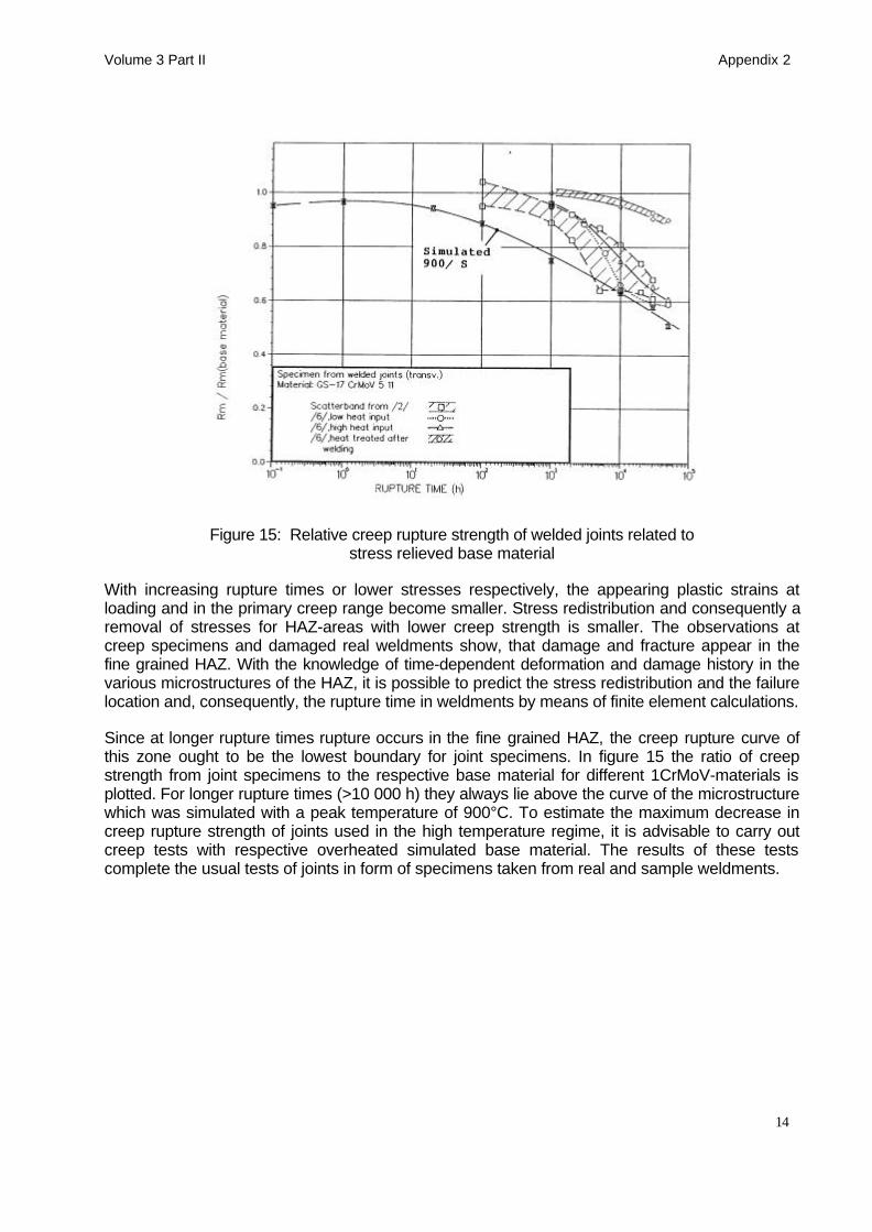
Figure 15: Relative creep rupture strength of welded joints related tostress relieved base material
With increasing rupture times or lower stresses respectively, the appearing plastic strains atloading and in the primary creep range become smaller. Stress redistribution and consequently aremoval of stresses for HAZ-areas with lower creep strength is smaller. The observations atcreep specimens and damaged real weldments show, that damage and fracture appear in thefine grained HAZ. With the knowledge of time-dependent deformation and damage history in thevarious microstructures of the HAZ, it is possible to predict the stress redistribution and the failurelocation and, consequently, the rupture time in weldments by means of finite element calculations.
Since at longer rupture times rupture occurs in the fine grained HAZ, the creep rupture curve ofthis zone ought to be the lowest boundary for joint specimens. In figure 15 the ratio of creepstrength from joint specimens to the respective base material for different 1CrMoV-materials isplotted. For longer rupture times (>10 000 h) they always lie above the curve of the microstructurewhich was simulated with a peak temperature of 900°C. To estimate the maximum decrease increep rupture strength of joints used in the high temperature regime, it is advisable to carry outcreep tests with respective overheated simulated base material. The results of these testscomplete the usual tests of joints in form of specimens taken from real and sample weldments.

Volume 3 Part II Appendix 2
15
5.2 GLEEBLE weldability tests on advanced 9-12% chromium steels
As part of the European COST-501/III programme „Materials for advanced steam cycles“, basicinvestigations on the weldability and long-time creep behaviour of advanced 9-12%Cr wereperformed at TU Graz [3]. Welding simulation using a Gleeble device was applied on pipes of P91,E911 and a tungsten containing cast steel G-X12CrMoWVNbN 10 1 1. The creep rupturebehaviour of the base material P91 and X20CrMoV 12 1 is compared with the creep rupturestrength of crossweld specimens in figure 16 [4]. It is obvious that the creep rupture strength ofcrossweld samples is significantly lower at higher temperature than that of the base material.
Gleeble simulations representing the manual metal arc welding process were applied to produceHAZ simulated microstructures. The cooling time between 800°C and 500°C was 21.6 s, seefigure 8. Special attention was laid on the evaluation of the soft zone in the HAZ by metallographicinvestigations, using light microscopy and TEM, hardness tests, and constant strain rate tests. Inaddition, long-time creep rupture tests were performed to study the effect of the soft zone, whichusually determines the locus of creep fracture.
Figure 16: Creep rupture strength of base material and crossweld specimens of pipe steel P91and X20CrMoV 12 1 [4].

Volume 3 Part II Appendix 2
16
The experiments revealed clearly that the creep strength drop in tungsten modified steel grades isless pronounced than in steel grade P91. This result was found in simulated samples as well asin real weldments.
5.2.1 Hardness profile
Hardness profiles across a weld seam of material P91 show clearly a tendency to form a softzone in the fine grained HAZ after post-weld heat treatment (PWHT), see figure 17. The hardnessin this particular zone is about 20 HV lower than in the unaffected base material. The hardnessprofiles of steel grades E911 and G-X12CrMoWVNbN 10 1 1 show a similar curve to that of P91.To define the zone in which maximum softening occurs, specimens were subjected to a HAZsimulation at different peak temperatures in the range between 760 and 950°C. The hardness wastested in the as-welded, simulated, and in the simulated and tempered condition. The temperingconditions after welding were 760°C/2 h air cooled for P91, 760°C/2 h for E911, and 730°C/12 hfor G-X12CrMoWVNbN 10 1 1.
150
200
250
300
350
400
450
0 10 20 30 40
P91, as welded
P91, 750°C/2h
E911, 760°C/2h
G-X 12, 730°C/12h
Distance, mm
Har
dnes
s, H
V10
Base Material HAZ Weld Metal
Figure 17: Hardness of weld seam in as-welded condition and after various post-weld heattreatments of P91, E911, and G-X12CrMoWVNbN 10 1 1[3].
The results of the hardness tests performed on the weld simulated microstructures of the threematerials are presented in figure 18 as a function of the peak temperature for both the temperedand as-welded condition. The hardness of the base materials tested is shown on the left side offigure 18. It is not influenced by thermal cycles with peak temperatures up to about 850°C. Thebeginning α/γ-transformation as a function of heat cycles can be observed by the increase ofhardness in the as-welded condition. After stress relieving, the hardening effect disappears and asmall hardness drop of about 10 HV can be detected for peak temperatures between 850 and950°C.

Volume 3 Part II Appendix 2
17
Har
dnes
s, H
V10
base material
150
200
250
300
350
400
450
500
550
700 750 800 850 900 950 1000
G-X 12 CrMoWVNbN 10 1 1, simulated thermal cycle
G-X 12 CrMoWVNbN 10 1 1, simulated thermal cycle+730°C/12h
P91, simulated thermal cycle
P91, simulated thermal cycle+760°C/2h
E911, simulated thermal cycle
E911, simulated thermal cycle+760°C/2h
Peak Temperature, °C
Figure 18: Results of hardness measurements on specimens of P91, E911, and G-X 12CrMoWVNbN 10 1 1 subjected to weld thermal cycle simulations (determination of soft,
intercritical zone) [3].
5.2.2 Constant strain rate tests on HAZ simulated materials
Constant strain rate tests at 600°C with &ε = 10-5 s-1 were applied on specimens which have beensubjected to HAZ simulation and subsequent tempering to investigate the principal influence of theHAZ softening effect on the creep resistance. This test method was first applied on this type ofsteel in [5]. The maximum stress gives an indication of the creep resistance of the micro-structures tested. The results of these tests, performed at 600°C on microstructures produced byweld simulation with different peak temperatures, are shown in figure 19. For the unaffected basematerial P91 a maximum stress of 280 N/mm2 and for G-X12CrMoWVNbN 10 1 1 a stress of 260N/mm2 was measured. For peak temperatures in the range of 875-920°C, there is a significantdecrease in the maximum stress, analogous with the decrease in hardness. The minimum in thestress versus peak temperature curve is for P91 at 250 MNm-2 and 920°C, and for G-X12CrMoWVNbN 10 1 1 at 240 MNm-2 and 875°C. The measured minimum of stress is about10% lower than that measured for the unaffected base material. The investigation of materialE911 is still in progress.

Volume 3 Part II Appendix 2
18
200
250
300
350
750 800 850 900 950 1000
G-X 12 CrMoWVNbN 10 1 1, simulated thermal cycle+730°C/12h
base material
P 91, simulated thermal cycle+760°C/2h
= 10 s-5 -1.
T = 600 °C
ε287 MPa
262 MPa 251 MPa
242 MPa
Peak Temperature, °C
Max
imum
Str
ess,
M
Pa
Figure 19: Results of constant strain rate tests on specimens of P91 andG-X12CrMoWVNbN 10 11 subjected to weld thermal cycle simulation followed by tempering.
5.2.3 Microstructural aspects
As described in [6], the microstructure of the normalised and tempered P91 steel consists oftempered martensite with a large amount of M23C6 and MX precipitates. Microscopic examinationof the specimens subjected to HAZ simulation thermal cycles revealed no significant change inthe microstructures when the peak temperature did not exceed 850°C. When the peaktemperature becomes higher than the AC1 temperature, depending on the shape of the thermalcycle, more and more austenite will be formed and transformed into martensite during cooling toroom or preheating temperature. When heating up to 920°C, the amount of martensite which wasfound under given conditions of our tests is about 70-90%. At this temperature, slightly above AC1,and the short times caused by the weld thermal cycle, no significant amount of precipitates andhence carbon and nitrogen go into solution. Therefore, the martensite formed under theseconditions lacks carbon. This is confirmed by the increase in hardness caused by higher peaktemperatures. Since very small amounts of carbon go into solution at these peak temperatures,the reprecipitation of M23C6 carbides and MX carbonitrides during the subsequent temperingtreatment is very limited. In addition, the coherent MX particles coarsen and coagulate and losetheir strengthening effect to a large extent. These effects also create a higher tendency towardsrecrystallisation in this area which, in connection with the overaging of the precipitates, results in asignificant softening of these fine grained zones of the HAZ which were heated up to 900-950°Cduring the weld thermal cycle after PWHT.
5.2.4 Creep rupture tests on HAZ simulated materials
Creep rupture tests were performed on samples which were designed to represent materialcontaining micro-structures caused by a peak temperature of 920°C (HAZ simulated). The resultsare shown in figure 20 and are compared with results obtained on creep samples made fromuninfluenced base material and welded joints. As can be seen, the creep resistance of plain HAZ

Volume 3 Part II Appendix 2
19
simulated materials falls for all investigated materials at high stress levels, significantly below thecreep resistance of that of the uninfluenced base material and of welded joints.
10
100
1000
1 10 100 1000 10000 100000
P 91, base material, 760°C/2h, (600°C)
GX-12, base material, 730°C/12h, (600°C)
E911, base material, 750°C/2h, (600°C)
P 91, simulated (Tp=920°C), 760°C/2h, (600°C)
GX-12, simulated (Tp=920°C), 730°C/12h, (600°C)
E911, welded joint, SMAW, 770°C/2h, (600°C)
E911, welded joint, SAW, 770°C/2h, (600°C)
GX-12, weld joint, SMAW, 730°C/12h, (600°C)
Cre
ep R
uptu
re S
tren
gth,
M
Pa
Time, h
Figure 20: Results of creep rupture tests of P91, E911, and G-X12CrMoWVNbN 10 1 1 basematerial, welded joint and soft zone HAZ simulated materials [3].
Comparing the behaviour of HAZ simulated material P91 to HAZ simulated materials E911 and G-X12CrMoWVNbN 10 1 1 it can be seen that the softening effect in the tungsten modified castingmaterial on the creep behaviour, at high stress levels, is lower than that of material P91. Creeptests performed on original welded and stress relieved samples of the cast steel show similarbehaviour. At high stress levels the creep resistance of HAZ simulated samples lay below that ofthe base material. As a result of the restraining effect in the HAZ region, the creep rupture strengthof welded joints are at the same level as that of the base material. At lower stress levels, HAZsimulated materials and welded joints show the same creep resistance.
5.2.5 Creep rupture tests on crossweld samples
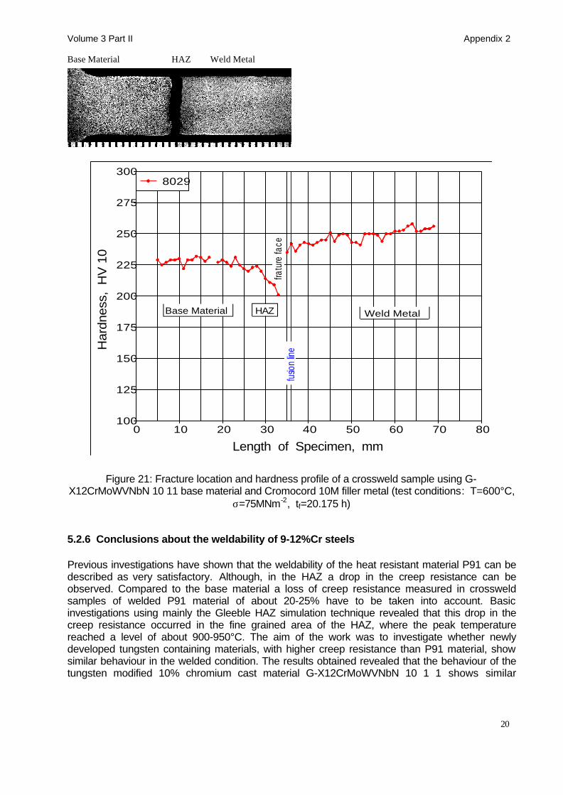
The current status of the creep tests at 600°C with a testing time of 30.000 hours is shown infigure 20. The cast steel G-X12CrMoWVNbN 10 1 1 and pipe version E911 appears to have acreep strength which is at least as high as that of modified 9%CrMo steel P91. Crossweldsamples of the repair weld (code E) of the pilot valve body was tested. At high stress levels thefracture is located in the base material. As the applied stress decreases and the rupture timeincreases, the fracture location shifts from the base material into the fine grained region in theHAZ. Results of microstructural investigation and hardness tests of broken creep rupture samplesare shown in figure 21.
Volume 3 Part II Appendix 2
20
Base Material HAZ Weld Metal
100
125
150
175
200
225
250
275
300
0 10 20 30 40 50 60 70 80
8029
Weld MetalHAZBase Material
fusio
n lin
efra
ture
face
Har
dnes
s, H
V 1
0
Length of Specimen, mm
Figure 21: Fracture location and hardness profile of a crossweld sample using G-X12CrMoWVNbN 10 11 base material and Cromocord 10M filler metal (test conditions: T=600°C,
σ=75MNm-2, tf=20.175 h)
5.2.6 Conclusions about the weldability of 9-12%Cr steels
Previous investigations have shown that the weldability of the heat resistant material P91 can bedescribed as very satisfactory. Although, in the HAZ a drop in the creep resistance can beobserved. Compared to the base material a loss of creep resistance measured in crossweldsamples of welded P91 material of about 20-25% have to be taken into account. Basicinvestigations using mainly the Gleeble HAZ simulation technique revealed that this drop in thecreep resistance occurred in the fine grained area of the HAZ, where the peak temperaturereached a level of about 900-950°C. The aim of the work was to investigate whether newlydeveloped tungsten containing materials, with higher creep resistance than P91 material, showsimilar behaviour in the welded condition. The results obtained revealed that the behaviour of thetungsten modified 10% chromium cast material G-X12CrMoWVNbN 10 1 1 shows similar

Volume 3 Part II Appendix 2
21
behaviour regarding the creep resistance in the HAZ to P91. Hardness tests, constant strain ratetests, and short time creep tests on HAZ simulated microstructures showed that also in tungstenmodified 9-10%Cr creep resistant steels a drop of the creep strengths in the welded area have tobe taken into account. The first results of HAZ simulated short time creep tests showed that thisdrop is less than observed in P91 pipe material. At stresses lower than 150 MNm-2, the fracturelocation shifts from the base material into the softened fine grained HAZ. At 600°C the data pointsof the weldments are below those of the base material by more than 25%. In the design of weldedcomponents made from this type of materials, this effect must be taken into account.
6. HAZ simulation to generate constitutive creep equations for FEM calculations
Fundamental experimental creep tests on HAZ-simulated samples, as described above, are anecessary information for any numerical model in order to extent the findings to other boundaryconditions or special cases. Although the fundamental equations to describe the physicalmetallurgy of welding related phenomena are known, it would be just an academic exercisewithout experimental support by e.g. Gleeble testing. Due to the versatile flexibility of the Gleebledevice, the material behaviour can be determined in a state (like directly after solidification) wherethe properties differ widely in comparison e.g. with heating up tests without prior melting. Also thefree combination between thermal and mechanical loading is a quite powerful possibility for anywelding research activity. The exact definition and application of the testing conditions togetherwith very accurate measurements of the material response allows to provide special modelparameters and on the other hand, the verification of any numerical result obtained by finiteelement models. An example of FEM-modelling of the creep behaviour in the HAZ with data fromHAZ-simulated creep samples is given in ref. [7,8].
7. Conclusion
Weldability tests by physical based methods, like by the Gleeble device, provide valuableinformation to the scientists as well as to welding engineers. Due to the rapid heating rate, theaccurate setting of any thermo-mechanical loading condition and the accurate measurement ofthe material response under rather complex testing conditions, very detailed information can begathered, which allows further developments of the base and weld materials as well as thewelding procedure (see also [9]). The versatile applicability and the feasibility to enlarge very smallHAZ regions in order to allow other material tests favours this physical simulation techniques incomparison with other weldability tests.
Volume 3 Part II Appendix 2
22
8. References
1 - Buchmayr, B.:"HAZ-CALCULATOR - A software package for metallurgical aspects ofweldability", Workshop Computer Aided Welding, 8.9.1992 Madrid; IIW-Doc.XII-1304-92
2 - Theofel,H. and K. Maile: Investigation of the structural formation, toughness and strength ofthe heat affected zone by means of weld simulated specimens of 1% CrMoV-steel, FinalReport COST 505 Project D17, December 1988
3 - Cerjak, H. and E.Letofsky, The Effect of Welding on the properties of advanced 9-12%Cr-steels. Science and Technology Vol.1, 1, 36-42 (1996).
4 - Brühl, F. H.Cerjak, H.Müsch, K.Niederhoff, and M.Zschau:VGB Kraftwerkstechnik 69, 12,1214-1231, (1989).
5 - Brühl, F., Verhalten des 9%-Chromstahles X10 CrMoVNb 9 1 und seiner Schweißver-bindungen im Kurz- und Langzeitversuch, Doctoral Thesis, TU-Graz, (1989).
6 - Cerjak, H. and F.Schuster, Weldability and behaviour of weldings of new developed creepresistant 9-10% Cr-Steels, Pivisto Italiano dillo Soldtissa 4/94, 467-473 (1994).
7 - Buchmayr, B., H.Cerjak, M.Witwer, K.Maile, H.Theofel, W.Eckert: "Experimental andnumerical investigations of the creep behaviour of the dissimilar weldment GS-17CrMoV 5 11and X20CrMoV 12 1", steel research 61, 1990, 6, 268-273
8 – Bhaduri, A.K., W.Gaudig, H.Theofel, K.Maile: Finite element modelling of the creepdeformation of T91 steel weldments at 600°C”, steel research 67, 1996, No.5, 215-220
9 - Kleber, S., J.Reiss, B.Buchmayr, H.Cerjak, E.Perteneder: „Influence of Constraining on theToughness Behaviour of Multi-Layer Weldments“, Proc. 7th International Symposium onPhysical Simulation of Casting, Hot Rolling and Welding, NRIM Tsukuba, Japan, Jan. 21-23,1997, 317-322

Volume 3 Part II Appendix 2
23
9. Literature on Creep Behaviour of HAZ simulated samples
1998:Ennis, P.J.; Wachter, O.Investigation into the properties of the 9% chromium steel 9 Cr-0.5 Mo-1.8 W-V-Nb with respect toits application as a pipework and boiler steel operating at elevated temperatures. Part 2:Properties of weldmentsVGB PowerTech v 78 n 1 1998. p 84-94
Ennis, P.J.; Wachter, O.Die Eigenschaften des 9%-Chromstahles vom Typ 9Cr-0,5Mo-1,8W-V-Nb im Hinblick auf seineVerwendung als Rohrleitungs- und Kesselbaustahl. Teil 2: Gefüge und mechanischeEigenschaften von SchweißverbindungenVGB-Kraftwerkstechnik 78, 1, 1998, 95-106
1997:Brozda, J.; Zeman, M.Weldability of 9Cr-1Mo-Nb, V P91 steel intended for service in the power industryWelding Research Abroad v 43 n 8-9 Aug-Sep 1997. p 58-68
Tsuchida, Y.; Okamoto, K.; Tokunaga, Y.Study of creep rupture strength in heat affected zone of 9Cr-1Mo-V-Nb-N steel by welding thermalcycle simulationWelding Research Abroad v 43 n 8-9 Aug-Sep 1997. p 27-33
Shinya, T.; Tomita, Y.:Simulated weld HAZ of Vanadium modified 2.25Cr-1Mo steelZeitschrift für Metallkunde 88, 10, 1997, 800-803
Otoguro, Y.; Matsurbara, M.; Itoh, I.Creep rupture strength of heat affected zone for 9Cr ferritic heat resisting steelsInternational Conference on Nuclear Engineering, Proceedings, ICONE 1997. ASME, New York,NY, USA. p 392 5-2019
Lundin, Carl D.; Liu, Peng; Zhou, Gang; Prager, MartinOptimization of the weldability and serviceability of 1 1/4Cr-1/2Mo for petrochemical applicationsFitness for Adverse Environments in Petroleum and Power EquipmentAmerican Society of Mechanical Engineers, Pressure Vessels and Piping Division (Publication)PVP v 359 1997. ASME, New York, NY, USA. p 325-331
Hyde, T.H.; Sun, W.; Becker, A.A.; Williams, J.A.Creep continuum damage constitutive equations for the base, weld and heat-affected zonematerials of a service-aged 1/2Cr 1/2Mo1/4V:21/4Cr1Mo multipass weld at 640 degree CJournal of Strain Analysis for Engineering Design v 32 n 4 Jul 1997. p 273-285
Tamaki, K,; Suzuki, J.; Kawakami, H.; Ryoke, K.:Effects of tempering conditions on temper embrittlement of the HAZ in 11/4Cr-1/2Mo steel. Studyof temper embrittlement of the HAZ in Cr-Mo steels. Report 2Welding International 11, 9, 1997, 705-714

Volume 3 Part II Appendix 2
24
Heuser,H.:Schweißtechnische Verarbeitung warmfester RohrwerkstoffeDrei R International 36, 12, 1997, 722-729
Cerjak, H.; Buchmayr, B.:The determination of weldability by using simulation techniquesProc. 7th International Symposium on Physical Simulation of Casting, Hot Rolling and Welding,NRIM, Japan, 21-23 Jan. 1997, p.291-298
Schuster, F.A.; Buberl, A.; Hanus, R.; Cerjak, H.:Erfahrungsbericht über die Herstellung von Turbinen- und Ventilgehäusen aus den neuen 9%Cr-StahlgußsortenVGB Kraftwerkstechnik 77, 7, 1997, 585-590
Maile, K.; Theofel, H.; Bendick, W.; Zschau, M.:Zeitstandverhalten von P91-SchweißverbindungenStahl u. Eisen 117, 8, 1997, 101-105
Lomozik, M.; Szaja, G.; Nowak, W.:The effect of repeated weld thermal cycles on the properties of a simulated heat affected zone in13HMF steelWelding International 11, 3, 1997, 173-178
Law, M.; Payten, W.Weld performance under creep using finite element modellingInternational Journal of Pressure Vessels and Piping v 72 n 1 Jun 1997. p 45-49
Otoguro, Y.; Matsurbara, M.; Itoh, I.Creep rupture strength of heat affected zone for 9Cr ferritic heat resisting steelsInternational Conference on Nuclear Engineering, Proceedings, ICONE1997. ASME, New York, NY, USA. p 392 5-2019
Mandziej, S.T.:Physical simulation of weldingThe ASM int. European Conf. on Welding and Joining Science and TechnologyMadrid 10-12.03.1997, 253-268
1996:Ennis, Philip J.; Wachter, Otto; Nickel, HubertusMechanical properties and microstructure of the 9% chromium steel NF616Fatigue/Fracture, NDE, Materials and Manufacturing Proceedings of theInternational Conference on Pressure Vessel Technology, ICPVT v 1 1996. ASME, New York, NY,USA. p 461-466
Bowers, R.J.; Nippes, E.F.Weld heat-affected-zone response to elevated-temperature deformationWelding Journal (Miami, Fla) v 75 n 11 Nov 1996. p 356-365
Tsuchida, Yutaka; Tsuda, Yukio; Tokunaga, YoshikuniEffects of alloying elements on the creep rupture time of high Cr ferritic steel weldments

Volume 3 Part II Appendix 2
25
Tetsu-To-Hagane/Journal of the Iron and Steel Institute of Japan v 82 n 6 Jun 1996. p 526-531
Bhaduri, Arun Kumar; Gaudig, Wolfgang; Theofel, Heinrich; Maile, KarlFinite element modelling of the creep deformation of T91 steel weldments at 600 degree CSteel Research v 67 n 5 May 1996. p 215-220Indacochea, J.E.; Kim, G.S.Reheat cracking studies on simulated heat-affected zones of CrMoV turbine rotor steelsJournal of Materials Engineering and Performance v 5 n 3 Jun 1996. P.353-364
Buddy Damm, E.; Lasday, Stanley B.Metallurgical physical simulation system and examples of practical applicationsIndustrial Heating v 63 n 1 Jan 1996. p 23-29
Lundin, C.D.; Khan, K.K.:Fundamental studies of the metallurgical causes and mitigation of reheat cracking in 11/4Cr-1/2Mo and 21/4Cr-1Mo steelsWRC Bulletin 409, 1996, 1-117
Theilig, H.:Numerische Simulation des Kriechverhaltens von SchweißverbindungenDrei R International 35, 8, 1996, 484-491
1995:Kojima, T.; Hayashi, K.; Kajita, Y.:HAZ softening and creep rupture strength of high Cr ferritic steel weldmentsISIJ International 35, 10, 1995, 1284-1290
Parker, J.D.; Stratford, G.C.:Microstructure and performance of 1,25Cr0,5Mo steel weldmentMaterials at High Temperature 13, 1, 1995, 37-45
1994:Lundin, C.D.; Qiao, C.-Y.P.Microstructural investigation of the weld HAZ in a modified 800H alloyJournal of Engineering for Gas Turbines and Power, Transactions ofthe ASME v 116 n 3 Jul 1994. p 629-634
1993:Ferguson, HugoPhysical simulation makes inroads in advanced materials testingAdvanced Materials & Processes v 143 n 4 Apr 1993. p 33-36